


ON Series m UPS
ON Series m
UPS
Introduction
Technical
Support
Please read and save these instructions. This manual
contains important instructions for the ON Series m
UPS family. Follow these instructions during the
unpacking, installation and maintenance of the
Uninterruptible Power Supply (UPS) and batteries.
If you have a problem with the UPS, please refer to
this manual before calling Technical Services. The
Troubleshooting Section starting on page 16
addresses most UPS-related issues.
Thank you for selecting this uninterruptible power
supply (UPS). ONEAC’s ON Series offers the most
reliable protection from the harmful effects of
electrical line disturbances for your computing and
communications equipment. ONEAC’s ISO 9001
certification represents our commitment to building
world-class products. W e take pride in e very unit that
leaves our manufacturing facility
ONEAC
contact ONEAC Technical Services:
NOTE: All calls received befor e 7 a.m. or after 7p.m.
Central Standard Time are forwarded to a cell
phone. An ONEAC T echnical Support Representative
will return your call within one half hour between 5
p.m. and 10 p.m. Central Standard Time . Except for
emergencies, calls received between 10 p.m. and 7
a.m. will be returned during normal business hours.
Please check with ONEAC Technical Services
before attempting to repair or return any ONEAC
product. If an ONEAC unit needs repair or
replacement, ONEAC Technical Services issues a
Return Material Authorization (RMA) number along
with instructions on how to return the unit.
®
offers 24-hour technical support. To
• North America: (800) 327-8801 (opt. 3) or
(847) 816-6000 (opt. 3)
• Europe: +44 (0) 2380 610311
• email: ts@oneac.com.
ON Series m UPS User Instruction Manual 1

Safety
Safety
Class 1 equipment
Equipment not suitable for use in the presence
of a FLAMMABLE ANESTHETIC MIXTURE
WITH AIR or WITH OXYGEN OR NITROUS
OXIDE.
Not designed, intended or authorized for use in
systems intended to support or sustain life.
For more details on life critical applications please
refer to full disclaimer in Appendix A: Warranty on
page 18 at the end of this manual.
WARNING: This equipment services power from
more than one source. The output receptacles may
have voltages present even when the unit is
unplugged.
UPSs present a different safety issue than most
electrical equipment because unplugging the UPS
puts it into backup mode. Unplugging the UPS does
not remove the electrical charge. To ensure that the
UPS is off, turn the power switch “OFF” before
unplugging the UPS from the wall outlet.
CAUTION: This unit is intended to be used in a
system that has a grounded neutral conductor.
CAUTION: Operating this equipment without
proper grounding may present a risk of electrical
shock.
Do not use A C adaptors with only tw o conductors to
connect the input line cord to the wall socket as this
will not connect the earth ground to the equipment.
WARNING: Dangerous voltages are present within
this unit! There ar e no user -serviceable parts inside.
Any repairs or modifications by the user may result
in out-of-warranty repair charges, unsafe electrical
conditions, or violation of electrical code.
Do not remove the cover. All repairs should be done
by qualified service personnel. Voltages inside the
UPS may be lethal. Internal components are
powered even when the po wer switch is in the “OFF”
2 ON Series m UPS User Instruction Manual

Features
position. Even with the battery disconnected and the
unit unplugged, energy is stored in high voltage
capacitors and represents a severe shock hazard.
Features
The ON Series m UPS models are listed for
UL2601-1 and CSA-C22.2 compliance and carry the
CE Mark for testing to the EN60601-1 standard for
Medical Electrical equipment. Designs are
compliant with all specification parameters for Class
I, equipment (such as earth leakage and enclosure
leakage currents). Units are available in 120 V and
230 V 50/60 Hz with IEC connectors to facilitate
country-specific connector compatibility or NEMA
5-15R receptacles on the “A” models. An optically
isolated communications interface is standard.
Your ONEA C ON Series m UPS features full output
isolation and power conditioning with V irtual Kelvin
®
Ground
level of protection from power line disturbances
available.
Intelligent battery management system includes:
• Battery condition monitoring and status alerts
• Low battery indication
• Hot-swap, user-replaceable battery
• Battery charge indication
• ONBoost
• Controlled inverter shutdown if battery is
ONEAC UPSs also feature a five-year w arranty. See
Appendix A, page 18 for full warranty details.
See Appendix B: Typical Runtime on page 20 for
battery runtimes. Full product specifications are
available in Appendix C: Specifications and
Characteristics on page 21.
output filtering. This provides the highest
®
, low line voltage compensation
without battery depletion
depleted
ON Series m UPS User Instruction Manual 3
Unpacking and Inspection
Unpacking and
Inspection
Installation
Changing Frequency
Before shipment, this product was tested, inspected
and found to be free of mechanical and electrical
defects. Upon receipt of your UPS, carefully
examine the packing containers for any sign of
physical damage. Notify the carrier immediately if
damage is present. After inspecting, carefully
unpack the UPS. Retain the packaging materials for
reuse or dispose of the materials properly. Once
unpacked, inspect and test the unit for hidden
damage that may have occurred in transit. If damage
is evident, contact ONEAC Technical Services.
When selecting a location for your UPS, be sure that
the unit is near a properly wired AC electrical outlet
and is easily accessible for all other connections.
Leave at least 2 inches of clearance on each side of
the UPS for proper ventilation.
CAUTION: Do not cover or install the UPS in a
confined or enclosed space.
This ON Series m UPS was designed to operate at
frequencies of either 50 Hz or 60 Hz.
The table below shows the frequency settings as
shipped from the factory.
Table 1. Frequency Settings
Model From Factory Adjustable To
ONm 300 I, ONm 600 I 50 Hz 60 Hz
ONm 300 J, ONm 600 J 60 Hz 50 Hz
ONm300 A, ONm600 A 60 Hz 50 Hz
If an adjustment is necessary , perform the follo wing:
CAUTION: Before proceeding, be sure the UPS is
“OFF” and disconnected from the utility power.
4 ON Series m UPS User Instruction Manual
Installation
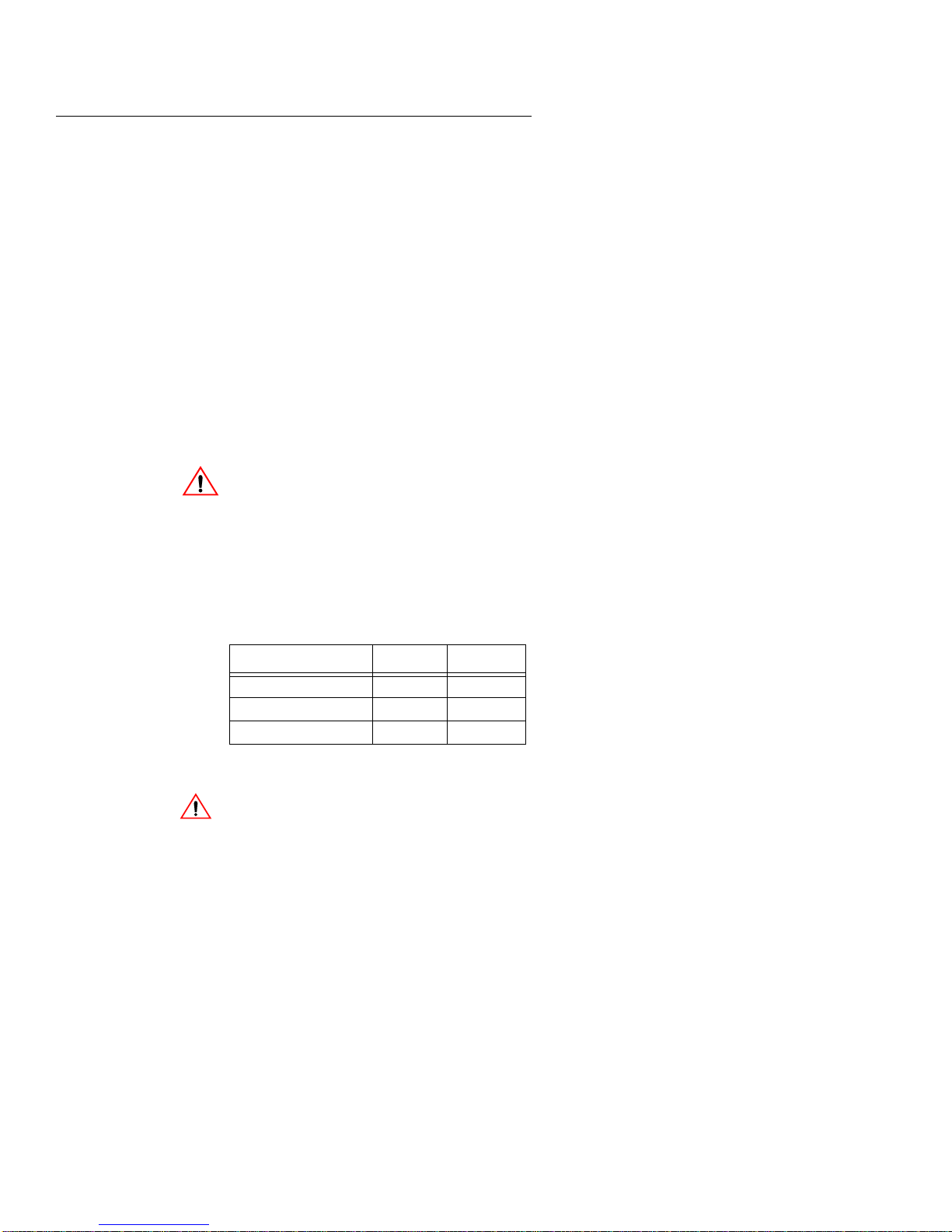
1. Lay the UPS on its right side.
2. Remove and retain the tw o Phillips head screws
at the bottom front of the unit that secure the
battery access door (fig. 1).
3. Carefully open the access door, then slide the
batteries out of the unit.
WARNING: Do not contact the exposed battery
terminals due to the presence of electrical charge.
4. The frequency selector switch, located at the top
of the UPS battery access panel, can be set to the
desired frequency using a small, standard
screwdriver or similar tool (fig. 1).
fig. 1: Frequency Selector Switch
5. Circle the selected frequency on the UPS label
for later reference.
6. With the battery terminals toward the rear of the
unit, slide the battery (pack) into the UPS. Make
sure the battery wires retract without binding.
7. Close the battery access door and secure with the
(2) screws removed in step 2. Return the desktop
UPS to the upright position.
Connecting External
Battery Enclosure(s)
ON Series m UPS User Instruction Manual 5
For additional runtime, some ON Series m UPSs can
use extra batteries housed in a separate enclosure.
Use only ONEAC model ONMXBC-217. The UPS
power module and battery enclosure(s) are shipped
separately.
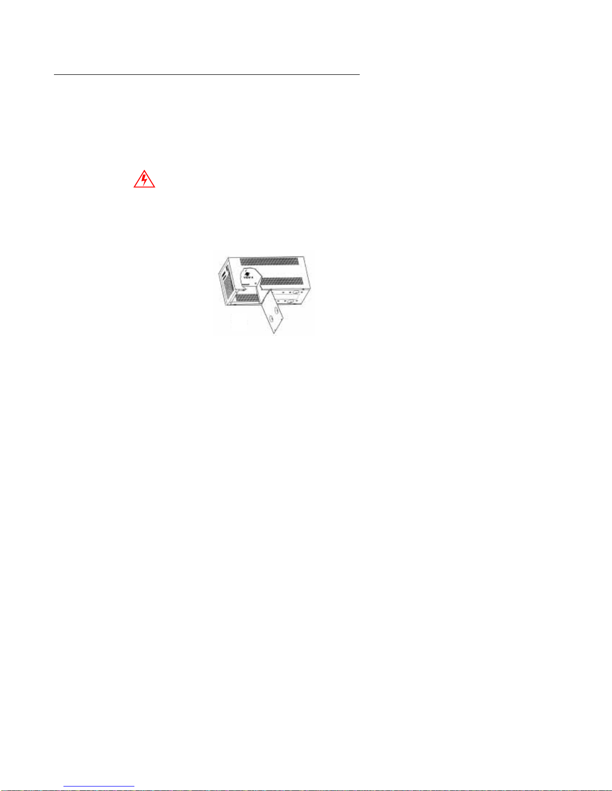
1. Connect the battery cable from the closest
battery enclosure to the external battery
receptacle on the UPS, see fig. 2.
Installation
2. Connect the battery cable from the next external
battery enclosure (if any) to the external battery
receptacle on the battery enclosure connected in
the previous step.
Repeat step 2 to connect additional external battery
enclosures.
fig. 2: ON Series UPS and External Battery Connections
Connections
Before beginning, shut down and unplug the
equipment to be protected. DO NOT make any
connections or attempt to use any of the equipment
until all the following connection instructions have
been reviewed and completed.
The I and J model UPSs are equipped with (1)
IEC320 (M) Input connector and (4) IEC320 (F)
output connectors, as shown in fig. 4. The A model
UPSs have (1) IEC320 (M) input connector and
either (2) or (4) NEMA 5-15R hospital grade
receptacles, as shown in fig. 5.
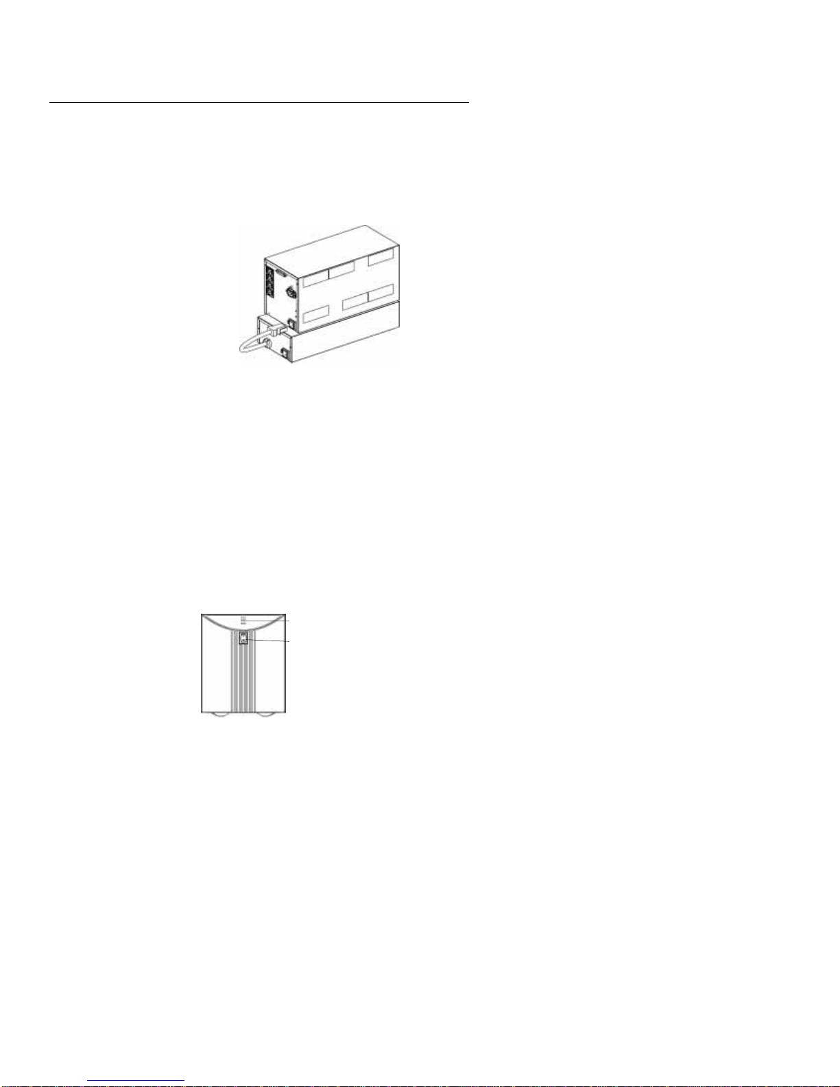
Indicator Lights
Power Switch
fig. 3: ON Series m UPS Front Panel
6 ON Series m UPS User Instruction Manual

IEC 320 (M) Input
Connector
IEC 320 (F) Output
Connectors
External Battery
ONm 300 ONm 600
ONm 300
A Models
Input Connector
fig. 4: ON Series m UPS I and J Models Back Panel
IEC 320 (M) Input
Connector
IEC 320 (F) Output
Connectors
External Battery
Input Connector
ONm 600
A Models
Installation
fig. 5: ON Series m UPS A Models - Back Panel
Load to UPS
ON Series m “A” models have (2/4) NEMA 5-15R
Receptacles and are shipped with a hospital grade
IEC 5-15P line cord. Use the supplied line cord to
connect the UPS to the AC power source. Connect
the protected devices directly to the 5-15R
receptacles on the UPS. On ON Series I and J models
a 6 foot IEC 320 (M/F) cord is provided for
connection of one device to the UPS. If more than
one device will be connected to the UPS, use
additional IEC 320 (M/F) cords as shown in figure 4.
Contact ONEAC for additional IEC 320 (M/F) cords
if needed.
ON Series m UPS User Instruction Manual 7
Installation
1. Disconnect the input power cord(s) from the
device(s) the UPS will be protecting.
NOTE: One of the disconnected power cords will be
used as the input power cord for the UPS.
2. Use IEC 320 (M/F) cord(s) to connect the
device(s) to the UPS IEC 320 (F) output
connectors.
Contact ONEAC Technical Support if your
equipment does not have a detachable IEC 320
power cord.
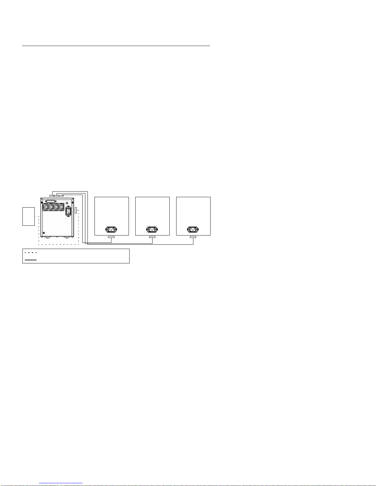
UPS to Power Source
T o connect the UPS to the AC power source, use the
input power cord supplied with the device to be
protected.
Connect the UPS to the AC utility power source as
shown in figure fig. 6.
Utility
Power
ONm UPS
Input power cord disconnected from protected device
IEC320 M/F power cord, (1) provided
fig. 6: Connecting Load(s) to UPS and Connecting UPS to AC Power Source
Device #1 to
be Protected
Device #2 to
be Protected
Device #3 to
be Protected
8 ON Series m UPS User Instruction Manual

Operating Instructions
Operating
Instructions
Power Switch
Self Test
With the UPS connected to a properly wired AC
input power source, toggle the power switch to the
( | ) “ON” position. Power is immediately supplied to
the output connectors.
Toggling the power switch to the( ) “standby”
position will turn the power to the output connectors
“OFF”. The internal charger will continue to char ge
and maintain the battery as long as the line cord is
connected to a live input AC power source.
Indicator
Lights
Power
Switch
fig. 7: ON Series m UPS Front Panel
The UPS checks vital functions when it is first
plugged in and indicates the status with the three
LEDs on the front panel. A green LED indicates
normal A C output. A blinking yellow LED sho ws the
battery is being charged. The UPS will continuously
monitor the condition of the battery. If the battery
cannot be charged, is disconnected or takes too long
to charge, a code is represented in the LED Display.
NOTE: The System Code Status Chart on the back of
the UPS (and on page 11 of this manual) provides a
quick refer ence for interpretation of the system status
LEDs.
On Battery
ON Series m UPS User Instruction Manual 9
If the AC input power source to the UPS rises too
high, too low or fails, the UPS will switch to the
internal inverter to deliver power to the outlets from
the battery(ies). The LEDs will indicate that the UPS
is on battery. An audible alarm will also sound every
minute.

Operating Instructions
Low Battery
Overload
Battery Replacement
When the battery voltage falls to a predetermined
value, the audible alarm will sound continuously and
the green and yellow LEDs will blink. If the UPS
continues to operate in this mode for two minutes or
more, the UPS will shutdown and remove power
from the output connectors.
When power returns, the UPS will return to on-line
operation and the battery(ies) will automatically
recharge.
If the load on the UPS exceeds its capacity, the red
and green LEDs will blink. The audible alarm will
sound once every minute.
If the UPS is heavily overloaded, the audible alarm
will sound continuously and will shut down in a few
seconds. The input breaker may also trip. T o reset the
breaker, first turn the UPS power switch to the
“OFF” position, remove the load and push the
breaker back into its housing. If the electronic
overload has tripped, the UPS will hav e to be reset by
toggling the power switch “OFF”, then “ON” to
restore output power.
If the UPS has determined that the battery is no
longer functional, the green and red LEDs will be on
continuously and the yellow LED will flash. The
audible alarm will sound every five minutes.
Indicator Lights
10 ON Series m UPS User Instruction Manual
GREEN - When the green LED is on, either solid or
blinking, power is being supplied to the output. If
blinking, it indicates the UPS is on inverter or there
is an overload condition.
YELLOW - When the yellow LED is on solid, the
UPS is on inverter . If blinking, it indicates the battery
is charging when on line or low battery if running on
inverter .
RED - When the red LED is on solid, it indicates
there is a problem with the battery charger or

●
❋ O ❋
Operating Instructions
inverter. If blinking, it indicates no battery, overload
or high line and no battery present.
Table 2. System Code Status Chart
Power Battery Fault Unit Status
O O O OFF
O O ON/AC Present
●❋❋
●❋ O ON AC/Battery Charging
●❋● ON AC/Replace Battery
❋● O ON Battery Power
❋❋ O ON Battery/Battery Low
OO ❋
O ●●
OO ●
O = Off, ● = On, ❋ = Blinking
ON AC/No Battery
ON AC/Overload
Off/Overload
Off/No AC - Fault
Off/Unit Fault
Communications
(Factory Installed
Options)
The isolated Basic Interface Option will send On
Battery and Low Battery signals to the host
computer. It will also accept a shutdown signal to
turn the inverter off to conserve battery life.
Pins 1 and 10 (simulated relay closures) are open
collector transistor outputs which must be pulled up
to a common reference supply no greater than +15V
DC. They are opto-isolated open collector transistors
capable of a maximum noninductive load of 10mA
DC. Pin 11 is the common for all of the relay closure
pins and is isolated from the UPS chassis ground.
Pins 20 and 21 are used to shut down the UPS when
it is operating on battery . A positi v e signal (3 to 24V
DC) on pin 20 with respect to pin 21 shuts down the
UPS. A signal at or belo w ground allows the UPS to
keep running.
ON Series m UPS User Instruction Manual 11

Replacing Battery(ies)
The shell of the interface connector is connected to
the UPS chassis ground.
Table 3. Pin Signals
Interface Pin No. Signal
1 Low Battery - normally open
10 Line Fail - normally open
11 Output Signal Common
20 Shutdown (to UPS)
21 Shutdown (to UPS)
Interface Port
ONm 300 ONm 600
fig. 8: ON Series m UPS Rear Panel
Replacing
Battery(ies)
12 ON Series m UPS User Instruction Manual
NOTE: To obtain new battery(ies), contact ONEAC
Technical Services at (847) 816-6000, or toll free at
(800)-327-8801, ext. 3. In Europe, dial
+44 (0) 1235 534721.
Battery replacement is a safe procedure that is
isolated from electrical hazards. You can leave the
UPS and attached loads powered “ON” during the
procedure. If the unit is “ON, ” the audible alarm will
sound when the battery is disconnected and the
yellow and red LEDs will blink.
NOTE: The UPS cannot protect against power
outages while the batteries are disconnected.

Replacing Battery(ies)
Procedures
1. Lay the UPS on its right side.
2. Open the battery access door on the bottom by
removing the two (2) Phillips head screws at the
front. Retain the screws for use in step 8 later.
3. Carefully open the battery access door and slide
the batteries out of the unit.
4. For the ONm Series 300 VA UPS disconnect the
black wire, then the red wire from the battery
pack.
For the ONm Series 600 VA UPS remove the
battery connector by squeezing the two “ears” on
the sides of the connector and pulling straight
out.
WARNING: Once the wires are removed from the
battery(ies), use caution to not contact the exposed
battery terminals due to the presence of electrical
charge.
5. For the ONm Series 300 VA UPS, using the new
battery(ies), connect the red wire to the red
positive (+) terminal on the battery.
NOTE: In the next step be aware that a small ar c may
occur while connecting the black wir e to the battery
terminal.
6. Connect the black wire to the (-) terminal on the
battery.
For the ONm Series 600 VA UPS, insert the
battery connector in the plug in the battery
compartment.
NOTE: The plug is polarized and only will fit in one
way.
7. With the battery terminals toward the rear of the
unit, slide the battery (pack) into the UPS. Make
sure the battery wires retract without binding.
8. Close the battery access door and secure with the
(2) screws removed in step 2. Return the desktop
UPS to the upright position.
9. Dispose of the old battery pack according to
ON Series m UPS User Instruction Manual 13

Replacing Battery(ies)
ON Series m UPS
Battery Wires
Battery
fig. 9: ON Series m UPS Battery Replacement
current environmental regulations. See Battery
Disposal, below, if you would like ONEAC to
dispose of battery.
Replacing External
Battery Enclosure(s)
For additional runtime, some ON Series m UPSs can
use extra batteries housed in a separate enclosure.
The UPS power module and battery enclosure(s) are
shipped separately.
NOTE: The UPS and attached loads may remain
powered ON during the battery enclosure(s)
replacement procedures.
The batteries inside the external battery enclosure(s)
are not user-replaceable. The entire battery enclosure
must be replaced or the enclosure may be returned to
ONEAC for battery replacement.
To disconnect the battery cable coming from an
external battery to the UPS or another external
battery, squeeze the two locking “ears” on the sides
of the battery connector and pull straight out (see fig.
10).
fig. 10: ON Series m External Battery Replacement
14 ON Series m UPS User Instruction Manual

Battery Disposal
Connect the battery cable from the closest battery
enclosure to the external battery receptacle on the
UPS, see fig. 2.
Connect the battery cable from the next external
battery enclosure (if any) to the external battery
receptacle on the battery enclosure connected in the
previous step.
Repeat to connect additional external battery
enclosures.
Battery Disposal
UPS Disposal
UPS batteries contain toxic and acidic materials.
Disposal method must adhere to local/national
recycling laws. Dispose of the battery in one of three
ways:
1. Return batteries prepaid to ONEAC for proper
recycling. Contact ONEAC Technical Services
at (847) 816-6000, toll free at (800) 327-8801
option 3 or in Europe at +44 (0) 1235 534721 for
an RMA number. Mark the RMA number on the
packing slip and shipping carton.
2. Phone ONEAC Corporation for the number of a
local battery collection site (US only).
3. Make arrangements with a local auto shop that
collects automotive batteries for reprocessing.
CAUTION: DO NOT dispose of battery in a fir e. The
battery may explode. Do not open or mutilate the
battery or battery enclosure. Released electrolyte is
harmful to the skin and eyes and is toxic.
Once your UPS has reached the end of its useful life
and it is necessary to dispose of the unit:
1. Remove the batteries as instructed in Replacing
Battery(ies) on page 12.
2. Dispose of the batteries as instructed in Battery
Disposal on page 15.
3. Dispose of the unit in accordance with local/
national recycling or disposal ordinances.
ON Series m UPS User Instruction Manual 15

Troubleshooting
Troubleshooting
ONEAC offers 24-hour technical support. If you
have questions or problems regarding your ON
Series m UPS:
1. Refer to the T roubleshooting table on page 17 for
corrective or recommended action.
2. If you are unable to troubleshoot the problem,
contact Technical Services. Refer to page 1,
Technical Support, for the correct telephone
number in your area. T echnical Services will ask
you to describe the problem. They will help solve
the problem over the telephone or issue a Return
Material Authorization (RMA) number along
with instructions on how to return the UPS for
repair.
NOTE: You will need to supply the service
repr esentative with the UPS part number and serial
number. You can access these numbers on the back
panel of the unit on a label located near the
receptacles.
Always check with ONEAC Technical Services
before attempting to repair or return any ONEAC
product.
16 ON Series m UPS User Instruction Manual

Troubleshooting
If you have questions or problems regarding you ON Series m UPS, refer to the
troubleshooting table below.
Table 4. Troubleshooting
Problem Possible Cause Solution
UPS will not turn ON
UPS operates on battery
even with line voltage
present.
Fault LED is ON.
Fault LED is blinking
Front Panel Switch not
“ON”.
UPS’s input circuit
breaker tripped.
Unit not plugged in. Plug unit into wall outlet.
UPS’s input circuit
breaker tripped.
High or low line. Contact qualified electrician.
Out of frequency range.
If yellow LED is blinking,
the battery needs to be
replaced.
If yellow LED is off or on
solid, there is an internal
UPS fault.
If yellow LED is blinking,
there is no battery
connected or detected.
If green LED is blinking
or off, the output is
overloaded.
Switch the Power Switch to (I)
Reduce the load on the UPS by
unplugging the load and press
the circuit breaker in on the rear
panel.
Reduce the load on the UPS by
unplugging the load and press
the circuit breaker in on the rear
panel.
Check for UPS compatibility
with power source.
Allow batteries to charge for 4
hours. If the problem continues,
replace the battery(ies).
Do not attempt to use the UPS.
Turn the UPS off, unplug from
the power line and call
Technical Service:
(800)-327-8801, opt. 3
immediately.
Connect install or replace the
battery(ies).
Reduce the load on the UPS
until the LED goes out. If green
LED is off, recycle power switch
to reset.
ON Series m UPS User Instruction Manual 17

Appendix A: Warranty
Appendix A:
Warranty
Batteries
Life Critical
Applications
ONEAC products are warranted free from defects in
materials and workmanship for five years. This
warranty is limited to repairing or replacing, at
ONEAC’s option, any defective component, circuit
board, or module contained within the product only
when it is returned with an ONEAC Return Material
Authorization (RMA) number to ONEAC or to an
ONEAC-designated repair facility. In all cases, the
customer is responsible for shipping charges to and
from ONEAC or the ONEAC-designated repair
facility.
Certain modules or peripherals included with the
product, but not manufactured by ONEAC,
including but not limited to batteries or battery
enclosures, are warranted for two years or the extent
of the manufacturer’s warranty, whichever is longer.
While ONEAC belie ves it designs and manufactures
very reliable products, many of the vendors that
ONEAC sources components from do not
recommend or endorse the use of their products in
life critical applications. By extension, ONEAC
must adhere to the same business policy and does not
recommend the use of our products in life critical
applications.
Disclaimer
18 ON Series m UPS User Instruction Manual
ONEAC products are not designed, intended or
authorized for use in systems intended to support or
sustain life, or for any other application in which the
failure of the ONEAC product could create a
situation where personal injury or death may occur.
Should the Buyer purchase or use ONEAC product
for any such unintended or unauthorized application,
the Buyer shall indemnify and hold ONEAC and its
officers, employees, subsidiaries, affiliates and
distributors harmless against all claims, costs,
damages and expenses, and reasonable attorney fees
arising out of, directly or indirectly, any claim or
personal injury or death associated with such
unintended or unauthorized use, even if such claim
alleges that ONEAC was negligent regarding the
design or manufacture of the part.

Appendix A: Warranty
Limitations of
Warranty
Exclusive Remedies
Return Procedure
This limited warranty does not cover any losses or
damage resulting from shipment to or from the
customer, or from improper installation,
inappropriate environment, abuse, modifications,
adjustments, or unauthorized repair.
For full details of the warranty, see ONEAC
Warranty, Policy and Procedures (part number
955-053).
Except as set forth herein and except as to title, there
are no warranties, express or implied, or any
affirmations of fact or promises by ONEAC for the
products, their merchantability, or fitness for any
particular purpose. In no event shall ONEAC be
liable for lost profits, goodwill or any other special or
consequential damages.
T o return a UPS, contact ONEA C Technical Support
for a Return Material Authorization (RMA) number.
This number must be marked on the shipping carton
and packing slip of the unit returned. The customer
is responsible for repair charges for damages
incurred in shipment that result from inadequate or
improper packing of the product.
ON Series m UPS User Instruction Manual 19

Appendix B: Typical Runtime
Appendix B:
Typical Runtime
Table 5. Typical Runtime by System Load
Typical Runtime by System
Load
VA LOAD RUNTIME (HOURS:MINUTES)
75 VA 0:41 1:32
100 VA 0:21 1:09
150 VA 0:16 0:40
200 VA 0:10 0:30
250 VA 0:07 0:20
300 VA 0:05. 0:15
NOTE: Due to application specific conditions, your actual run time may be different.
ONm300 A, I and J Models
One 12V, 7AH Battery
ONm300D A, I and J Models
Two 12V, 7AH Batteries
Table 6. ON Series m 600 VA Extendable Runtimes
Typical Runtime
by System Load
VA LOAD RUNTIME (HOURS:MINUTES)
100 VA 1:05 4:40 8:50* 10:30* 13:30* 16:40*
200 VA 0:35 2:40 5:00* 7:00* 9:00* 11:10*
400 VA 0:15 1:20 2:20* 3:30* 4:30* 5:30*
600 VA 0:05 0:30 1:10* 2:20* 3:00* 3:45
NOTE: Due to application specific conditions, your actual run time may be different.
NOTE: External Battery - Two 12V, 17AH per battery enclosure.
* Values shown are calculated.
ONm600X
Two 12 V, 7 AH
Batteries
Plus1
External
Battery
Plus2
External
Batteries
Plus 3
External
Batteries
Plus 4
External
Batteries
Plus 5
External
Batteries
20 ON Series m UPS User Instruction Manual

Appendix C: Specifications and Characteristics
Appendix C: Specifications and Characteristics
Table 7. Physical/Electrical Specifications
and Performance Characteristics*
Specification and Characteristics ONm300J ONm600J ONm300I ONm600I ONm300A ONm600A
Maximum Load - VA/Watts
Load Power Factor Range UPS .65 to 1.0 (3) - will support loads rated 0.5 to 1.0
Crest Factor <3
Nominal Input Voltage 120 VA C 230 V A C 120 VAC
Low Limit for On-line Operation
@ 50% Load
High Limit for On-line Operation
@ 50% Load
Unit Start-up Range 93-138VAC 190-266 VAC 93-138 VAC
Frequency Limits (on-line) 50/60 Hz +/- 5%
Input Connection IEC 320 (M) inlet
Input Over Current Protection resettable, linked dual pole (L & N) breaker
Boost Voltage
Output Voltage on Backup
@ 50% Load
On Battery Waveshape amplitude stabilized stepped sine-wave
On Battery Frequency 50/60 Hz +/- 1%
T ransf er Time 4mS, typ
Output Connection (4) IEC 320 (F) connectors (2/4) 5-15R
Battery Type maintenance free, spill proof, sealed lead-acid
Typical Battery Life 3-6 years, depending on number of discharges and ambient temperature
Recharge Time (60% Recovery) 6-10 hours
Communications isolated basic signaling
Interface Connector 25 pin male sub D style
Output Signals
Input Signal
Maximum Collector Voltage (VDC) 15
Maximum Collector Current (mADC) 10
Maximum Output Voltage @ 5
mADC
300/200 600/400 300/200 600/400 300/200 600/400
87 VA C 183 VAC 87 VA C
138 VA C 266 VAC 138 VAC
approximately 10% boost to output voltage when input voltage falls below 80%
of nominal
110 VAC ± 10% 220 VAC ±10% 110 VAC ± 10%
on battery (pin10) / low battery (pin 1)
(TRUE condition causes “short” to RETURN signal (pin 11))
inverter shut down [pin 20 (+) to pin 21 (-)]
(high shuts down inverter)
0.8
ON Series m UPS User Instruction Manual 21

Appendix C: Specifications and Characteristics
Table 7. Physical/Electrical Specifications
and Performance Characteristics* (Continued)
Specification and Characteristics ONm300J ONm600J ONm300I ONm600I ONm300A ONm600A
Output Type opto-isolated open collector transistor
Input Type opto isolator input diode with anti-parallel diode and 500 ohms in series
Table continued on next page
Minimum Input to
Activate Shutdown (mA)
Maximum Input Current (mA) 20
Operating Temperature 0º to +40ºC (32 to 104ºF)
Storage Temperature -15 to 45ºC (+5 to 113ºF)
Relative Humidity 0 to 95%, non-condensing
Operating Elevation 0 to 3,000 m (0 to 10,000 ft)
Storage Elevation 0 to 15,000 m (0 to 50,000 ft)
Size (HxWxL) inches 7.38 x 6.00 x 15.00
Shipping Weights lbs.
Surge Voltage Withstand Capability ANSI/IEEE C62.41 Category A&B, 6KV/200 and 500 Amp, 100KHz Ringwave
Surge Voltage Let-Through
Normal and Common Mode Clamping
Response Time
* ± 2 volt tolerance on all measurements.
Less than 10V normal mode (L-N), less than 0.5V Common mode (N-G) when
subjected to C62.41 6kV Cat. A pulse
1
37/43
(single/double battery)
instantaneous
22 ON Series m UPS User Instruction Manual

Appendix C: Specifications and Characteristics
T able 8. Physical/Electrical Specifications and P erformance Characteristics
for ONMXBC-217 External Battery
Specifications and
Characteristics
Voltage 2x 12 V
Current 40 A
Batteries two at 12 V, 17 AH
Operating Temperature 0º to +40ºC (32 to 104ºF)
Storage Temperature -15 to 45ºC (+5 to 113ºF)
Relative Humidity 0 to 95%, non-condensing
Operating Elevation 0 to 3,000 m (0 to 10,000 ft)
Storage Elevation 0 to 15,000 m (0 to 50,000 ft)
Size (HxWxL) inches (cm) 3.75” x 7.0” x 17” (9.5 x 18 x 43)
Shipping Weights lbs. (kg) 38 (17)
ONMXBC-217
ON Series m UPS User Instruction Manual 23

Appendix C: Specifications and Characteristics
Safety & Approvals
Table 9. Emissions Test Regulations
Emissions Test Regulations
United States 47 CFR Part 15 Subpart B:1999
Canada Interference-Causing Equipment Standard (ICES-003 Issue 2, Rev.1)
Europe EMC-Directive 89/336/EEC as amended by 92/31/EEC and 93/68/EEC
EN 50091-2 / 09.95 (UPS Equipment)
EN 50081-1 / 01.92 (Generic Emission - Residential, Commercial and
Light Industrial)
EN 60601-1-2 / 05.93 (Medical equipment)
EN 55011 / (ISM Equipment)
EN 55022 / 08.94 (ITE Equipment)
EN 61000-3-2 / 04.95
EN 61000-3-3 / 01.95
24 ON Series m UPS User Instruction Manual

Appendix C: Specifications and Characteristics
Table 10. Immunity Test Regulations
Immunity Test Regulations
Europe EMC-Directive 89/336/EEC as amended b y 92/31/EEC and 93/68/EEC
EN 50091-2 / 09.95 (UPS Equipment)
EN 50082-1/08.97 (Generic Immunity - Residential, Commercial and
Light Industrial)
EN 60601-1-2 / 05.93 (Medical equipment)
EN 61000-4-2 / 03.95 (IEC 1000-4-2 / 01.95)
EN 61000-4-3 / 1995 (IEC 1000-4-3 / 02.95)
ENV 50204 / 03.95
EN 61000-4-4 / 03.95 (IEC 1000-4-4/01.95)
EN 61000-4-5 / 03.95 (IEC 1000-4-5 / 02.95)
EN 61000-4-6 / 07.96 (IEC 1000-4-6 / 03.96)
EN 61000-4-11 / 08.94 (IEC 1000-4-11 / 06.94)
IEC 1000-2-2 / 09.95
Table 11. Safety Regulations
Safety Regulations
UL1778 (Uninterruptible Power Supply Equipment)
United States
Canada CSA 22.2
Europe
UL2601-1 (Medical Electrical Equipment, Part 1 General Requirements
for Safety)
EN 60601-1 Medical Electrical Equipment
EN60950 Information Technology Equipment as amended by
EN 50091-1 Standard for Uninterruptible Power Systems
ON Series m UPS User Instruction Manual 25
 Loading...