


ON Series®e UPS
For use with ON Series e 200 - 600 VA, 60 Hz model
User Instruction Manual
Desktop models
Wallmount models
R
A HIGHER LEVEL OF CONFIDENCE

ON Series e UPS
ON Series e UPS
User Instruction Manual
IMPORTANT SAFETY INSTRUCTIONS
SAVE THESE INSTRUCTIONS.
Please read and save these instructions. This manual contains important
instructions for the ON Series e UPS. Follow these instructions during the
unpacking, installation and maintenance of the ON Series e UPS. If you have a
problem with the unit, please refer to Troubleshooting on page 24 before calling
ONEAC Technical Services.
Licenses and Trademarks
ONEAC, ON Series, ONBoost, and Virtual Kelvin Ground are all registered
trademarks of ONEAC Corporation. All other trademarks, product and corporate
names are the property of their respective owners.
ONEAC USA
27944 North Bradley Road
Libertyville, IL 60048-9700
USA
Telephone: (847) 816-6000
Toll Free: (800) 327-8801
Facsimile: (847) 680-5124
Entire contents copyright © 2005 ONEAC Corporation. All rights reserved. Reproduction in whole or
in part without permission is prohibited. All information subject to change without notice.
913-383 Rev. D 9/05
ON Series e UPS User Instruction Manual
ONEAC EUROPE
George Curl Way
Southampton, Hampshire SO18 2R Y
United Kingdom
Telephone: +44 (0) 2380 610311
Facsimile: +44 (0) 2380 610852


Introduction ....................................................................................... 1
Registering Your ONEAC UPS .............................................................1
Technical Support ...............................................................................1
FCC Compliance ................................................................................2
Safety .................................................................................................3
Set-up and Installation ........................................................................4
Unpacking and Inspection ............................................................4
Long Term Storage ......................................................................4
Ventilation ................................................................................... 4
Grounding the Unit ......................................................................4
Set-up ..........................................................................................5
Connections ................................................................................6
Self Test .......................................................................................9
Front Panel ................................................................................10
Communications (Factory Installed Options) ............................... 12
Features and Specifications ...............................................................14
Physical and Electrical Specifications ...........................................14
Specifications and Characteristics ...............................................15
Typical Runtime .........................................................................17
Safety & Approvals .....................................................................19
Battery Considerations .....................................................................20
Replacing Battery(ies): Standard and Wall-mount Units ..............20
Replacing External Battery Enclosure(s) .......................................22
Battery Disposal ................................................................................23
UPS Disposal ....................................................................................24
Troubleshooting ............................................................................... 24
Warranty .......................................................................................... 26
Batteries ....................................................................................26
Limitations of Warranty ..............................................................26
Exclusive Remedies .....................................................................26
Return Procedure ....................................................................... 26
ON Series e UPS User Instruction Manual i


Introduction
Introduction
Registering Y our ONEAC UPS
Technical Support
Thank you for selecting this uninterruptible
power supply (UPS). ONEAC’s ON Series
offers the most reliable protection from the
harmful effects of electrical line disturbances
for your computing and communications
equipment. ONEAC’s ISO 9001 certification
represents our commitment to building
world-class products. We take pride in every
unit that leaves our manufacturing facility
T o ensure that your ON Series e UPS model and
serial number are registered, complete and mail
the enclosed postage-paid warranty card or go
on line at www.oneac.com.
ONEAC offers 24-hour technical support. To
contact ONEAC Technical Services:
• North America: (847) 816-6000, option 3
or toll free (800) 327-8801, option 3.
• Europe: +44 (0) 2380 610311
• email: ts@oneac.com.
Please check with ONEAC Technical Services
before attempting to repair or return any
ONEAC product. If an ONEAC UPS needs
repair or replacement, ONEAC Technical
Services will issue a Return Material
Authorization (RMA) number along with
instructions on how to return the UPS.
ON Series e UPS User Instruction Manual 1

FCC Compliance
FCC Compliance
ATTENTION: Changes or modifications to this
unit not expressly approved by the party
responsible or in FCC compliance could void
the user’s authority to operate the equipment.
This equipment was tested and complies with
the limits for a Class A digital device, pursuant
to Part 15 of FCC Rules. These limits are
designed to provide reasonable protection
against harmful interference when the UPS is
operating in a commercial environment. The
UPS generates, uses, and can radiate radio
frequency energy. If installation and use is not
in accordance with the instruction manual, it
may cause harmful interference to radio
communications.
ATTENTION: Operation of this equipment in a
residential area may cause harmful radio
communications interference. The user is
responsible for correcting the interference.
Please check with ONEAC Technical Services
before attempting to repair or return any
ONEAC product. If an ONEAC UPS needs
repair or replacement, ONEAC Technical
Services will issue a Return Material
Authorization (RMA) number along with
instructions on how to return the UPS.
2 ON Series e UPS User Instruction Manual
Safety
Safety
WARNING: This equipment services power
from more than one source. The output
receptacles may have voltages present even
when the unit is unplugged.
UPSs present a different safety issue than most
electrical equipment because unplugging the
UPS puts it into backup mode. Unplugging the
UPS does not remove the electrical charge. To
ensure that the UPS is off, turn the power switch
“OFF” before unplugging the UPS from the
wall outlet.
CAUTION: This unit is intended to be used in a
system that has a grounded neutral conductor.
CAUTION: Operating this equipment without
proper grounding may present a risk of
electrical shock.
Do not use AC adaptors with only two
conductors to connect the input line cord to the
wall socket as this will not connect the earth
ground to the equipment.
WARNING: Dangerous voltages are present
within this unit! There are no user-serviceable
parts inside. Any r epairs or modifications by the
user may result in out-of-warranty repair
charges, unsafe electrical conditions, or
violation of electrical code.
Do not remove the cover. All repairs should be
done by qualified service personnel. Voltages
inside the UPS may be lethal. Internal
components are powered even when the power
switch is in the “OFF” position. Even with the
battery disconnected and the unit unplugged,
energy is stored in high voltage capacitors and
represents a severe shock hazard.
ON Series e UPS User Instruction Manual 3

Set-up and Installation
Set-up and
Installation
Unpacking and
Inspection
Long Term Storage
When selecting a location for your UPS, be sure
that the unit is near a properly wired AC
electrical outlet and is easily accessible for all
other connections: equipment to UPS, optional
battery enclosure(s) and/or optional
communications cable.
NOTE: When connecting the UPS, make sure
that the receptacle has power available and is
not controlled by a wall switch.
Before shipment, this product was tested,
inspected and found to be free of mechanical
and electrical defects. Upon receipt of your
UPS, carefully examine the packing containers
for any sign of physical damage. Notify the
carrier immediately if damage is present. After
inspecting, carefully unpack the UPS. Retain
the packaging materials for reuse or dispose of
the materials properly. Once unpacked, inspect
and test the unit for hidden damage that may
have occurred in transit. If damage is evident,
contact ONEAC Technical Services.
Improper long-term UPS storage may damage
the UPS battery and invalidate the battery
warranty . Unplugging a UPS from its A C utility
power source for an extended period of time
results in lost battery charge. Restoration of
charge to maximum capacity requires 24 - 48
hours.
Ventilation
Grounding the Unit
4 ON Series e UPS User Instruction Manual
The ventilation requirement for the ON Series e
UPS is a minimum of 2 inches (50 mm) of
clearance on all sides.
Do not cover or install the UPS in a confined or
enclosed space.
T o eliminate shock hazard, the ON Series e UPS
needs to be connected to a properly grounded
AC receptacle.
Before applying power , verify that the av ailable
line voltage matches the voltage listed on the
rear-panel label.
Set-up and Installation
CAUTION: Interruption of the protective
grounding conductor or disconnection of the
protective earth terminal presents a potential
shock hazard that could result in personal
injury and damage to the equipment.
Set-up Mounting Wall-mount Extended Runtime
Units and Battery Enclosure(s)
Mount the power unit and battery enclosure(s)
on a 3/4 inch plywood (minimum) backboard.
Use the enclosed four (4) 1/4 inch x 1 inch
slotted-hex, washer-head wood scre ws. (See fig.
1)
NOTE: When mounting the UPS and external
battery enclosure(s), make sure that all
connections can be made easily without
twisting, pinching or stressing the cables or
connectors. Two (2) inches of clearance are
necessary if the battery enclosure(s) is mounted
below the UPS. Five (5) inc hes are needed if the
battery enclosure(s) is mounted on either side of
the UPS. Due to the rising characteristics of
heat, mounting the battery enclosure(s) above
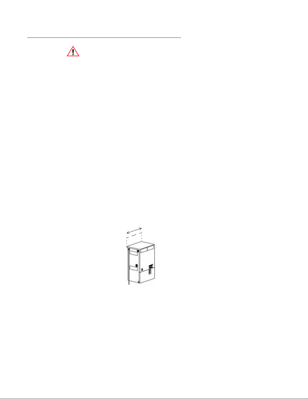
the UPS is not recommended.
1. Draw a straight, lev el, horizontal 8 inch line
on the backboard. This represents where the
top of the enclosure will be.
2. Mark two screw locations, on the line, 7-3/8
inch apart.
8”
X
X
3/8”
7
fig. 1: Mounting the ON Series e Wall-mount UPS
ON Series e UPS User Instruction Manual 5

Set-up and Installation
3. Drill a 3/16 inch diameter hole at each screw
location.
4. Drive the screws into the backboard at the
screw locations. Allow a 1/8 inch gap
between the screw head and the backboard.
5. Mount the unit by sliding the keyhole slots,
located on the back of the enclosure, over
the screws.
6. Check to ensure that the unit is level.
7. When level, drill a 3/16 inch diameter hole
through the holes in the mounting tabs at the
bottom of the enclosure. Then drive the
remaining two screws.
8. Repeat steps 1 through 7 to mount any
external battery enclosure(s).
Connections
Before beginning, shut down and unplug the
equipment to be protected. DO NOT make any
connections or attempt to use any of the
equipment until all the following connection
instructions have been re viewed and completed.
Connection External Battery Enclosure(s)
Wall-mount External Battery Enclosure(s)
1. Connect the battery cable from the closest
battery enclosure to the external battery
receptacle on the UPS, see fig. 2.
2. Connect the battery cable from the next
external battery enclosure (if any) to the
external battery receptacle on the battery
enclosure connected in the previous step.
6 ON Series e UPS User Instruction Manual

ON Series e
Wall-mount UPS
Set-up and Installation
3. Repeat step 2 to connect additional external
battery enclosures.
UPS External Battery
Cable Receptacle
External Battery Cable
External Battery Cable
Receptacle for Additional
Battery Enclosure(s)
External Battery
Enclosure of the ON Series e
Wall-mount UPS
fig. 2: ON Series e Wall-mount UPS and External Battery
Connections
Desk-top External Battery Enclosure(s)
For additional runtime, some ON Series e UPSs
can use extra batteries housed in a separate
enclosure. Use only ONEAC model
ONEXBC-217. The UPS power module and
battery enclosure(s) are shipped separately.
1. Connect the battery cable from the closest
battery enclosure to the external battery
receptacle on the UPS, see fig. 3.
2. Connect the battery cable from the next
external battery enclosure (if any) to the
external battery receptacle on the battery
enclosure connected in the previous step.
ON Series e UPS User Instruction Manual 7

Set-up and Installation
Repeat step 2 to connect additional external
battery enclosures.
fig. 3: ON Series UPS and External Battery Connections
Connecting Equipment to the UPS
Before beginning, shut down and unplug the
equipment to be protected. DO NOT make any
connections or attempt to use any of the
equipment until all the following connection
instructions have been re viewed and completed.
The UPS is equipped with a six foot attached
line cord with a 5-15P plug. The 200 and 300
VA wall-mount models provide two 5-15R
output receptacles and the 200 - 600 VA
desk-top models provide four 5-15R output
receptacles (see fig. 4).
5-15R
Output
Receptacles
fig. 4: ON Series e UPS Back Panels
These connections are for common electrical
equipment that have NEMA 5-15P po wer cords.
Contact ONEAC Technical Support if your
equipment does not provide these connections.
1. Disconnect the equipment to be protected
from its existing power source.
8 ON Series e UPS User Instruction Manual
5-15R
Output
Receptacles

Set-up and Installation
2. Insert the connector(s) from the equipment
to be protected into the 5-15R receptacles
on the back of the UPS.
NOTE: ALL AC power supply cords from each
component in the system to be protected must be
connected to the UPS or complete protection
will not be achieved.
3. Insert the UPS’ s 5-15P plug into a properly
grounded and wired AC receptacle.
4. With the UPS connected to a properly wired
AC input power source, toggle the power
switch to the ( | ) “ON” position.
Power is immediately supplied to the output
connectors. The ON Series e will perform a
self-test when turned on.
T oggling the power switch to the( ) “standby”
position will turn the power to the output
connectors “OFF”. The internal charger will
continue to charge and maintain the battery as
long as the line cord is connected to a live input
AC power source.
Power SwitchPower Switch
fig. 5: ON Series e UPS Power Switch
Self Test
ON Series e UPS User Instruction Manual 9
The UPS checks vital functions when it is first
plugged in and indicates the status with the
three LEDs on the front panel.
• A green LED indicates normal AC output.
• A blinking yellow LED shows the battery is
being charged.

Set-up and Installation
The UPS will continuously monitor the
condition of the battery . If the battery cannot be
charged, is disconnected or takes too long to
charge, a code is represented in the LED
display.
NOTE: The System Code Status Chart on the
back of the UPS or inside the wall-mount
battery compartment (and on page 12 of this
manual) provides a quick reference for
interpretation of the system status LEDs.
Front Panel On Battery
If the AC input power source to the UPS rises
too high, too low or fails, the UPS will switch to
the internal inverter to deliver power to the
outlets from the battery(ies). The LEDs will
indicate that the UPS is on battery. An audible
alarm will also sound every minute.
Low Battery
When the battery voltage falls to a
predetermined value, the audible alarm will
sound continuously and the green and yellow
LEDs will blink. If the UPS continues to
operate in this mode for two minutes or more,
the UPS will shutdown and remove po wer from
the output connectors.
When power returns, the UPS will return to
on-line operation and the battery(ies) will
automatically recharge.
Overload
If the load on the UPS exceeds its capacity, the
red and green LEDs will blink. The audible
alarm will sound once every minute.
If the UPS is heavily overloaded, the audible
alarm will sound continuously and will shut
down in a few seconds. The input breaker may
also trip. T o reset the break er , first turn the UPS
10 ON Series e UPS User Instruction Manual

Set-up and Installation
power switch to the “OFF” position, remov e the
load and push the breaker back into its housing
(see fig. 6). If the electronic overload has
tripped, the UPS will have to be reset by
toggling the power switch “OFF”, then “ON” to
restore output power.
Circuit Breaker
ON Series e Wall-Mount
Circuit Breaker
ON Series e 400 - 600 ON Series e 200 -300
fig. 6: ON Series e UPS Circuit Breakers
Battery Replacement
If the UPS has determined that the battery is no
longer functional, the green and red LEDs will
be on continuously and the yellow LED will
flash. The audible alarm will sound every five
minutes.
Indicator Lights
GREEN - When the green LED is on, either
solid or blinking, power is being supplied to the
output. If blinking, it indicates the UPS is on
inverter or there is an overload condition.
YELLOW - When the yellow LED is on solid,
the UPS is on inverter. If blinking, it indicates
the battery is charging when on line or low
battery if running on inverter.
RED - When the red LED is on solid, it
indicates there is a problem with the battery
charger or inverter. If blinking, it indicates no
battery, overload or high line and no battery
present.
Circuit Breaker
ON Series e UPS User Instruction Manual 11

Set-up and Installation
Table 1. System Code Status Chart
Power Battery Fault Unit Status
O O O OFF
O O ON/AC Present
k k ON AC/No Battery
k O ON AC/Battery Charging
k l ON AC/Replace Battery
O k ON AC/Overload
l O ON Battery Power
k O ON Battery/Battery Low
O O k Off/Overload
O l l Off/No AC - Fault
O O l Off/Unit Fault
O = Off, ● = On, ❋ = Blinking
●
●
●
●
❋
❋
❋
Communications (Factory Installed Options)
The Basic Interface Port Option (see fig. 7) will
send On Battery and Low Battery signals to the
host computer. It will also accept a shutdown
inverter signal to conserve battery life.
Pins 5 and 8 are RS-232 static levels. Less than
five (5) volts indicates a normal or not true
condition. Greater than five (5) volts indicates
an alarm or true condition.
Pins 1, 10, 18, and 25 (simulated relay closures)
are open drain FET transistor outputs which
must have a pull-up resistor to a common
reference supply no greater than +40V DC. The
FETs are “N” channel type 2N7000. The load
should be limited to 25 mA DC, noninductive.
Pin 7 is the common for all of the relay closure
pins and is connected to the UPS chassis ground
reference.
Pin 20 is used to shut down the UPS when it is
operating on battery . A positi ve signal (3 to 24V
DC) with respect to pin 7 shuts down the UPS.
A signal at or below ground allows the UPS to
keep running.
12 ON Series e UPS User Instruction Manual

Set-up and Installation
The shell of the interface connector is connected
to the UPS chassis ground reference.
Pin No. Signal
1 Low Battery - normally open
5 Line Fail - RS-232 static levels
7 Signal Ground
8 Low Battery - RS-232 static levels
10 Line Fail - normally open
18 Line Fail - normally closed
20 Shutdown (to UPS)
25 Low Battery - normally closed
Interface Port Interface PortInterface Port
ON Series e Wall-Mount
ON Series e 400 - 600
fig. 7: ON Series e Interface Port
ON Series e 200 -300
ON Series e UPS User Instruction Manual 13

Features and Specifications
Features and
Specifications
Physical and Electrical
Specifications
Your ONEAC ON Series UPS features full
output isolation and power conditioning with
Virtual Kelvin Ground
provides the highest level of protection from
power line disturbances available.
Intelligent battery management system includes:
• Five-year warranty on power control systems
• Two-year warranty on batteries
• Battery condition monitoring and status alerts
• Low battery indication
• Hot-swap, user-replaceable battery
• Battery charge indication
• ONBoost
without battery depletion
• Controlled inverter shutdown if battery is
depleted
Surge voltage withstand capability: ANSI/
IEEE C62.41 Category A&B, 6 kV/200 & 500
Amp, 100 kHz ringwave
Surge voltage let-through (max): Less than 10 V
Normal mode (L-N), less than 0.5V Common mode
(N-G) when subjected to 6 kV ANSI/IEEE C62.41
Cat. A
Normal & common mode clamping response
time:
®
, low line voltage compensation
Instantaneous
®
output filtering. This
Transfer time (typical/max): 4/6 milliseconds
On battery output voltage: Pseudo sine wave
ONBoost: Boosts output voltage 10% above
input voltage if between -21% & -15% of nominal
Load power factor range (crest factor): UPS .65
to 1.0 (3) — will support loads rated 0.5 to 1.0 (<5)
Batteries: Sealed, maintenance-free lead acid
with a 3-6 year typical lifetime, user replaceable
Recharge time to 60% available capacity: 6-10 hrs
ONEAC UPSs also feature a five-year w arranty.
See Warranty Section on page 26 for full
warranty details.
14 ON Series e UPS User Instruction Manual

Features and Specifications
Specifications and
Characteristics
Specification and Characteristics
Part Numbers (single battery)
(double battery)
(wall-mount)
Maximum Load VA/W 200/135300/200 400/265 600/400
Load Power Factor Range UPS .65 to 1.0 - will support loads rated 0.5 to 1.0
Crest Factor <3
Nominal Input Voltage 120 VA C
Low Limit for On-line Operation 85 VAC
High Limit for On-line Operation 135 VAC
Frequency Limits (on-line) 60 Hz +/ -5%
Input Connection 6’ attached line cord with 5-15P plug
Input Over Current Protection resettable circuit breaker
ONBoost
Output Voltage (on battery) 115 VAC
On Battery Waveshape amplitude stabilized stepped sine-wave
On Battery Frequency 60 Hz +/- 1%
Transfer Time 4 mS, typical
Output Receptacles (desk-top models)
(wall-mount models)
Battery Type maintenance free, spill proof, sealed lead-acid
Typical Battery Life 3 - 6 years, depends on number of discharges and ambient temperature
Recharge Time (60% Recovery) 6-10 hours
External Battery Typical Recharge Time 20 hours/battery enclosure
Communications isolated basic signaling
Interface Connector 25 pin male sub D style
Output Signals - static on battery (pin5) / low battery (pin 8)
Input Signal - static
Output Signals - stimulated relay
Maximum Collector Voltage 25 VDC
Maximum Collector Current 25 mADC
ONe200A ONe300A ONe400A ONe600A
ONE200A-SB ONE300A-SB NA NA
ONE200DA-SB ONE300DASB ONE400DA-SB ONE600XA-SB
ONE200XA-W-SB ONE300XA-SB NA NA
Boosts output voltage 10% above input voltage if input is -21% to 15% of
nominal
(4) 5-15R (4) 5-15R (4) 5-15R (4) 5-15R
(2) 5-15R (2) 5-15R NA NA
5 VDC = true
inverter shut down [pin 20 (+) to pin 7 (grd)]
(+3 to +27 VDC shuts down inverter)
on battery (pin 10 N.N., pin 18 N.C.)
Low battery (pin 1 N.O., pin 25 N.C.)
Table continued on next page
≥
ON Series e UPS User Instruction Manual 15

Features and Specifications
Specification and Characteristics
Output Type open drain “N” channel FET 2N7000 or equivalent
Operating Temperature 0 to +40° C (32 to 104° F)
Storage Temperature -15 to 45° C (+5 to 113° F)
Relative Humidity 0 to 95%, non-condensing
Operating Elevation 0 to 3,000 m (0 to 10,000 ft.)
Storage Elevation 0 to 15,000 m (0 to 50,000 ft.)
Desk-top UPS (HxWxL) in.
Desk-top UPS Shipping Weights lbs. (kg)
(single/double battery)
Desk-top Extended Battery Enclosure
Shipping Weight lbs. (kg)
Wall-mount UPS (HxWxL) in. (cm)
Wall-mount UPS Ship Weight lbs (kg) 43 (20) 43 (20) NA NA
Wall-mount External Battery Enclosure
(HxWxL) in. (cm)
Wall-mount External Battery Enclosure
Ship Weight lbs (cm)
Surge Voltage Withstand Capability ANSI/IEEE C62.41 Category A&B, 6 kV/200 &500 Amp, 100 kHz Ringwave
Surge Voltage Let-through
Normal & Common Mode Clamping
Response Time
ONe200A ONe300A ONe400A ONe600A
7.4 x 6 x 15 7.4 x 6 x 15 7.8 x 7 x 16 7.8 x 7 x 16
(19 x 15 x 38) (19 x 15 x 38) (20 x 18 x 41) (20 x 18 x 41)
29/32 34/40 NA /45 NA/51
(18/15) (15/18) (NA/19) (NA/23)
NA NA NA 38 (17)
14.4 x 9 x 6.6 14.4 x 9 x 6.6 NA NA
(37 x 23 x 17) (37 x 23 x 17)
12.38 x 9 x 6.63 12.38 x 9 x 6.63 NA NA
(32 x 23 x 17) (32 x 23 x 17)
36 (16) 36 (16) NA NA
Less than 10 V Normal mode (L-N), less than 0.5 V Common mode (N-G)
when subjected to ANSI/IEEE C62.41 Cat. A
instantaneous
16 ON Series e UPS User Instruction Manual

Features and Specifications
Typical Runtime
Table 2. Runtime for the ON Series e 200, 300, and 400 VA Desktop UPS
Typical
Runtime by
System Load
VA LOAD RUNTIME (HOURS:MINUTES)
75 VA 0:28 0:53 0:41 1:32 1:15
100 VA 0:18 0:37 0:21 1:09 1:05
150 VA 0:12 0:25 0:16 0:40 0:50
200 VA 0:08 0:16 0:10 0:30 0:35
250 VA
300 VA
400 VA
NOTE: Due to application specific conditions, your actual run time may be different.
ONe200
One12 V, 7 AH
Battery
NA NA
NA NA
NA NA NA NA
ONe200D
Two 6 V, 10 AH
Batteries
One300
One 12 V, 7 AH
Battery
0:07 0:20 0:25
0:05 0:15 0:20
ONe300D
Two 12 V, 7 AH
Batteries
ONe400D
Two 12 V, 7 AH
Batteries
Table 2. ON Series e 600 Extendable Runtimes
Typical Runtime
by System Load
VA LOAD RUNTIME (HOURS:MINUTES)
100 VA 1:05 4:40 8:50* 10:30* 13:30* 16:40*
200 VA 0:35 2:40 5:00* 7:00* 9:00* 11:10*
400 VA 0:15 1:20 2:20* 3:30* 4:30* 5:30*
600 VA 0:05 0:30 1:10* 2:20* 3:00* 3:45
NOTE: Due to application specific conditions, your actual run time may be different.
NOTE: External Battery - Two 12V, 17AH per battery enclosure.
* Values shown are calculated.
ONe600X
Two 12 V, 7 AH
Batteries
Plus1
External
Battery
Plus2
External
Batteries
Plus 3
External
Batteries
Plus 4
External
Batteries
0:15
Plus 5
External
Batteries
ON Series e UPS User Instruction Manual 17

Features and Specifications
Table 2. ON Series e 200 Wall-mount Extendable Runtimes
Typical
Runtime by
System Load
VA LOAD RUNTIME (HOURS:MINUTES)
75 VA 1:32 6:32 12:25 — — —
100 VA 1:09 5:10 9:55 — — —
150 VA 0:40 3:33 6:49 10:19 — —
200 VA 0:30 2:35 4:53 7:37 9:49 —
NOTE: Due to application specific conditions, your actual run time may be different.
NOTE: External Battery - Two 12V, 17AH per battery enclosure.
ONe200X
Two 12 V, 7
AH Batteries
Plus1
External
Battery
Plus2
External
Batteries
Plus 3
External
Batteries
Plus 4
External
Batteries
Table 2. ON Series e 300 Wall-mount Extendable Runtimes
Typical
Runtime by
System Load
VA LOAD RUNTIME (HOURS:MINUTES)
75 VA 1:32 6:32 12:25 — — —
100 VA 1:09 5:10 9:55 — — —
150 VA 0:40 3:33 6:49 10:19 — —
200 VA 0:30 2:35 4:53 7:37 9:49 —
250 VA 0:20 1:55 3:32 5:40 7:22 8:44
300 VA 0:15 1:26 2:30 4:10 5:28 6:16
NOTE: Due to application specific conditions, your actual run time may be different.
NOTE: External Battery - Two 12V, 17AH per battery enclosure.
ONe300X
Two 12 V, 7
AH Batteries
Plus1
External
Battery
Plus2
External
Batteries
Plus 3
External
Batteries
Plus 4
External
Batteries
Plus 5
External
Batteries
Plus 5
External
Batteries
18 ON Series e UPS User Instruction Manual

Features and Specifications
Safety & Approvals
Table 3. Emissions Test Regulations
Emissions Test Regulations
United States 47 CFR Part 15 Subpart A
Canada Interference-Causing Equipment Standard (ICES-003 Issue 2, Rev.1)
Table 4. Safety Regulations
Safety Regulations
United States UL1778 (Uninterruptible Power Supply Equipment)
Canada CSA 22.2
ON Series e UPS User Instruction Manual 19

Battery Considerations
Battery
Considerations
Replacing Battery(ies): Standard and Wall-mount Units
NOTE:To obtain new battery(ies), contact
ONEAC Technical Services at (847) 816-6000,
or toll free at (800)-327-8801, opt. 3. In Eur ope,
dial +44 (0) 2380 610311 Battery replacement
is a safe procedure that is isolated from
electrical hazards. You can leave the UPS and
attached loads powered “ON” during the
procedure. If the unit is “ON,” the audible
alarm will sound when the battery is
disconnected and the yellow and red LEDs will
blink.
NOTE:The UPS cannot protect against power
outages while the batteries are disconnected.
1. Lay the UPS on its right side.
2. Open the battery access door on the bottom
by removing the two (2) Phillips head
screws at the front. Retain the screws for use
in step 8 later. The wall-mount UPS has a
battery access door latch on the front. To
open, press down and pull forward.
3. Carefully open the battery access door and
slide the batteries out of the unit.
4. ON Series e 200 and 300 VA UPSs:
disconnect the black wire, then the red wire
from the battery pack.
ON Series e 400 and 600 VA UPSs:
remove the battery connector by squeezing
the two “ears” on the sides of the connector
and pulling straight out.
WARNING:Once the wires are removed from
the battery(ies), use caution to not contact the
exposed battery terminals due to the pr esence of
electrical charge.
5. ON Series e 200 and 300 VA UPSs: using
the new battery(ies), connect the red wire to
the red positive (+) terminal on the battery.
20 ON Series e UPS User Instruction Manual

Battery Considerations
NOTE:In the next step be awar e that a small arc
may occur while connecting the black wire to
the battery terminal.
6. Connect the black wire to the (-) terminal on
the battery.
ON Series e 400 and 600 VA UPSs: insert
the battery connector in the plug in the
battery compartment.
NOTE:The plug is polarized and connector will
only fit in one way.
7. With the battery terminals to ward the rear of
the unit, slide the battery (pack) into the
UPS. Make sure the battery wires retract
without binding.
8. Close the battery access door and secure
with the (2) screws removed in step 2.
Return the desktop UPS to the upright
position. On the wall-mount UPS, be sure
the battery access door is completely closed
and secured by the door latch.
9. Dispose of the old battery pack according to
current environmental regulations. See
Battery Disposal on page 23, if you would
like ONEAC to dispose of battery.
ON Series e UPS
Battery Wires
Battery
fig. 8: ON Series e Desktop UPS Battery Replacement
ON Series e UPS User Instruction Manual 21

Battery Considerations
ON Series e Wall-mount UPS
Battery Wires
Battery
fig. 9: ON Series e Wall-mount UPS Battery Replacement
Replacing External Battery Enclosure(s)
For additional runtime, some ON Series e UPSs
supportsextra batteries housed in a separate
enclosure. The UPS power module and battery
enclosure(s) are shipped separately.
NOTE:The UPS and attached loads may
remain powered ON during the battery
enclosure(s) replacement procedures.
The batteries inside the external battery
enclosure(s) are not user-replaceable. The entire
battery enclosure must be replaced or the
enclosure may be returned to ONEAC for
battery replacement.
To disconnect the battery cable coming from an
external battery to the UPS or another external
battery, squeeze the two locking “ears” on the
sides of the battery connector and pull straight
out (see fig. 10).
fig. 10: Battery Connector
22 ON Series e UPS User Instruction Manual

Battery Disposal
For wall mounted batteries, after disconnecting
ALL battery cables, remove the two lower
mounting screws under the battery cabinet. Then
lift the cabinet straight up to disengage from the
upper two mounting screws (see fig. 11).
fig. 11: ON Series e Wall-mount UPS Battery Replacement
Battery Disposal
ON Series e UPS User Instruction Manual 23
UPS batteries contain toxic and acidic
materials. Disposal method must adhere to
local/national recycling laws. Dispose of the
battery in one of three ways:
1. Return batteries prepaid to ONEAC for
proper recycling. Contact ONEAC Technical
Services at (847) 816-6000, toll free at (
800) 327-8801 option 3 or in Europe at +44
(0) 2380 -610311 for an RMA number.
Mark the RMA number on the packing slip
and shipping carton.
2. Phone ONEAC Corporation for the number
of a local battery collection site (US only).
3. Make arrangements with a local auto shop
that collects automotive batteries for
reprocessing.
CAUTION:DO NO T dispose of battery in a fir e.
The battery may explode. Do not open or
mutilate the battery or battery enclosure.
Released electrolyte is harmful to the skin and
eyes and is toxic.

UPS Disposal
UPS Disposal
Troubleshooting
Once your UPS has reached the end of its useful
life and it is necessary to dispose of the unit:
1. Remove the batteries as instructed in
Replacing Battery(ies): Standard and
Wall-mount Units on page 20.
2. Dispose of the batteries as instructed in
Battery Disposal on page 23.
3. Dispose of the unit in accordance with local/
national recycling or disposal ordinances.
ONEAC offers 24-hour technical support. If
you have questions or problems regarding your
ON Series e UPS:
1. Refer to the Trouble Shooting table on
page 25 for corrective or recommended
action.
2. If you are unable to troubleshoot the
problem, contact Technical Services. Refer
to page 1, T echnical Support, for the correct
telephone number in your area. Technical
Services will ask you to describe the
problem. They will help solve the problem
over the telephone or issue a Return
Material Authorization (RMA) number
along with instructions on how to return the
UPS.
NOTE:You will need to supply the service
representative with the UPS part number and
serial number . You can access these numbers on
the back panel of the unit on a label located
near the receptacles.
Always check with ONEAC T echnical Services
before attempting to repair or return any
ONEAC product.
24 ON Series e UPS User Instruction Manual

Troubleshooting
If you have questions or problems regarding you ON Series e UPS, refer to the
troubleshooting table below.
Table 5. Troubleshooting
Problem Possible Cause Solution
UPS will not turn ON
UPS operates on battery
even with line voltage
present.
Fault LED is ON
Fault LED is blinking
Front Panel Switch not
“ON”.
UPS’s input circuit
breaker tripped.
Unit not plugged in. Plug unit into wall outlet.
UPS’s input circuit
breaker tripped.
High or low line. Contact qualified electrician.
Out of frequency range.
If yellow LED is blinking,
the battery needs to be
replaced.
If yellow LED is off or on
solid, there is an internal
UPS fault.
If yellow LED is blinking,
there is no battery
connected or detected.
If green LED is blinking
or off, the output is
overloaded.
Switch the Power Switch to (I)
Reduce the load on the UPS by
unplugging the load and press
the circuit breaker in on the rear
panel.
Reduce the load on the UPS by
unplugging the load and press
the circuit breaker in on the rear
panel.
Check for UPS compatibility
with power source.
Allow batteries to charge for 4
hours. If the problem continues,
replace the battery(ies).
Do not attempt to use the UPS.
Turn the UPS off, unplug from
the power line and call
Technical Service:
(800)-327-8801, opt. 3
immediately.
Connect install or replace the
battery(ies).
Reduce the load on the UPS
until the LED goes out. If green
LED is off, recycle power switch
to reset.
ON Series e UPS User Instruction Manual 25

Warranty
Warranty
Batteries
Limitations of Warranty
ONEAC products are warranted free from
defects in materials and workmanship for five
years. This warranty is limited to repairing or
replacing, at ONEAC’s option, any defective
component, circuit board, or module contained
within the product only when it is returned with
an ONEAC Return Material Authorization
(RMA) number to ONEAC or to an
ONEAC-designated repair facility. In all cases,
the customer is responsible for shipping charges
to and from ONEAC or the ONEA C-designated
repair facility.
Certain modules or peripherals included with
the product, but not manufactured by ONEAC,
including but not limited to batteries or battery
enclosures, are warranted for two years or the
extent of the manufacturer’s warranty,
whichever is longer.
This limited warranty does not cover an y losses
or damage resulting from shipment to or from
the customer, or from improper installation,
inappropriate environment, abuse,
modifications, adjustments, or unauthorized
repair.
For full details of the warranty, see ONEAC
Warranty, Policy and Procedures (part number
955-053).
Exclusive Remedies
Return Procedure
26 ON Series e UPS User Instruction Manual
Except as set forth herein and except as to title,
there are no warranties, express or implied, or
any affirmations of fact or promises by ONEA C
for the products, their merchantability , or fitness
for any particular purpose. In no event shall
ONEAC be liable for lost profits, goodwill or
any other special or consequential damages.
To return a UPS, contact ONEAC Technical
Support for a Return Material Authorization
(RMA) number. This number must be marked
on the shipping carton and packing slip of the
unit returned. The customer is responsible for
repair charges for damages incurred in shipment
that result from inadequate or improper packing
of the product.

ONEAC Corporation, a wholly owned subsidiary of Chloride Group, PLC was founded
in 1979. ONEAC designs and manufactures products that provide the highest level of
protection against power and data line disturbances, regardless of conditions.
ONEAC's comprehensive product lines include power conditioners, uninterruptible
power supplies, DC power solutions and voice & data line protection devices. With
ISO9001 certified manufacturing plants in the U.S. and U.K., ONEAC is dedicated to
demand-flow manufacturing and the highest quality standards.
Organizations whose productivity goals allow no possibility for system downtime use
ONEAC. They include many of the world's leading companies, in a wide range of
applications including telecommunication systems, information technology, retail
information systems, computer-integrated manufacturing systems, semiconductor test
equipment and biomedical instrumentation and information systems. Information on
ONEAC products and services is available on the Internet at www.oneac.com.
ONEAC USA ONEAC EUROPE
27944 North Bradley Road George Curl Way
Libertyville, IL 60048-9700 Southampton, Hampshire SO18 2RY
United States United Kingdom
Toll Free: (800) 327-8801 Tel: +44-(0)-2380 610311
Tel: (847) 816-6000 Fax: +44-(0)-2380 610852
Fax: (847) 680-5124
Visit our website: www.oneac.com
ONEAC, ON Series, Virtual Kelvin Ground and ONBoost are registered trademarks of
ONEAC Corporation. All other trademarks are the property of their respective companies.
Entire contents copyright © 2005 ONEAC Corporation. All rights reserved. Reproduction in
whole or in part without permission is prohibited. All information subject to change without
notice.
Printed in the U.S.A. Part No. 913-383 Rev. D
A Chloride Power Protection Company A Chloride Power Protection Company
R
R
A HIGHER LEVEL OF CONFIDENCE
ONEAC is a UL/BSI
registered firm,
Certification No.
A2900.
 Loading...