


ON Series User Instruction Manual
ON Series
®
User Instruction Manual
IMPORTANT SAFETY INSTRUCTIONS
SAVE THESE INSTRUCTIONS.
Please read and save these instructions. This manual contains important
instructions for the ON Series UPS family. Follow these instructions during the
unpacking, installation and maintenance of the UPS and batteries. If you have a
problem with the UPS, please refer to this manual before calling the Technical
Support Department. The Troubleshooting section on page 61 addresses most
UPS-related issues.
Licenses and Trademarks
ONEAC, ON Series, Virtual Kelvin Ground, Environmental Reference Ground
and MopUPS are all registered trade marks and ChangeUPS, ONBoost, and
ONEP
LUS
, are trademarks of ONEAC Corporation. All other trademarks, product
and corporate names are the property of their respective owners.
ONEAC USA
27944 North Bradley Road
Libertyville, IL 60048-9700
USA
Telephone: (847) 816-6000
Toll Free: (800) 327-8801
Facsimile: (847) 680-5124
ONEAC EUROPE
18 & 20 Blacklands Way
Abingdon Business Park
Abingdon, Oxfordshire OX14 1DY
United Kingdom
Telephone: +44 (0) 1235 534721
Facsimile: +44 (0) 1235 534197
Entire contents copyright © 2000 ONEAC Corporation. All rights reserved. Reproduction in whole or
in part without permission is prohibited. All information subject to change without notice.
913-300-1 Rev. E 4/00
ON Series User Instruction Manual

Contents
Introduction ....................................................................................... 1
Registering Your ONEAC UPS ............................................................. 1
Technical Support ............................................................................... 1
FCC Compliance ................................................................................ 2
Safety ................................................................................................. 3
(English) ....................................................................................... 3
Sicherheitshinweise ............................................................................ 4
(Deutsch) ..................................................................................... 4
Mesures de sécurité ............................................................................ 5
(Français) ..................................................................................... 5
Seguridad ........................................................................................... 6
(Español) ...................................................................................... 6
Theory of Operation ........................................................................... 7
AC Power Mode .......................................................................... 7
Battery Backup Mode ................................................................... 7
Inrush Tolerance .......................................................................... 9
Output Overload Protection ......................................................... 9
Setup and Installation .......................................................................11
Inspection and Unpacking .......................................................... 11
Testing ....................................................................................... 11
Environmental Reference Ground ............................................... 12
Setup Precaution ........................................................................ 13
Long Term Storage .................................................................... 13
Ventilation ................................................................................. 13
Grounding the Unit .................................................................... 14
Installing Standard ON2000 Units .............................................. 15
Installing ON2200XA Extended Runtime Units ............................ 16
Installing Standard Extended Runtime Units ............................... 17
Mounting Wallmount Extended Runtime Units and Battery
Enclosures ............................................................................ 21
Installing Wallmount Extended Runtime Units ............................ 22
Installing Rackmount Units ......................................................... 26
Front Panel Features and Controls .............................................. 27
Back Panel DIP Switch Settings ................................................... 29
Features and Specifications ............................................................... 30
Features ........................................................................................... 31
Options ...................................................................................... 32
Physical and Electrical Specifications ........................................... 33
Contents
ON Series User Instruction Manual i

Contents
Runtime Estimates ......................................................................42
Interface Specifications ...............................................................50
Accessories .......................................................................................51
UPS Monitoring Interfaces ..........................................................51
UPS Monitoring Software ...........................................................51
Installing and Removing Accessory Interface Cards .....................54
Battery Considerations ......................................................................55
Battery Maintenance ..................................................................55
Ordering New Batteries ..............................................................55
Battery Replacement ..................................................................56
Installing Battery Pack in Standard, Rack Mount and Wall Mount
Units .......................................................................................56
Replacing External Battery Cabinets ............................................59
Battery Disposal ..........................................................................60
Troubleshooting ................................................................................61
Checking the Size of the Load ....................................................61
Technical Support .......................................................................62
Warranty ..........................................................................................66
Units ..........................................................................................66
Batteries .....................................................................................66
Limitations of Warranty ..............................................................66
Exclusive Remedies .....................................................................66
Return Procedure .......................................................................66
Appendix A: Accessories Interface Capabilities ..................................67
Appendix B: Operating in Power Environments Below 110V Nominal 68
Appendix C: Accessing Remote Off ...................................................70
ii ON Series User Instruction Manual

Introduction
Introduction
Registering
Your ONEAC
UPS
Technical
Support
Thank you for selecting this uninterruptible power
source (UPS). ONEAC’s ON Series offers the most
reliable protection from the harmful effects of
electrical line disturbances for your computing and
communications equipment.
ONEAC’s ISO 9001 certification represents our
commitment to building world-class products. We
take pride in every unit that lea ves our manufacturing
facility .
To ensure that your ON Series model and serial
number are registered, complete and mail the
enclosed postage-paid warranty card.
ONEAC offers 24-hour technical support. Contact
ONEAC’s Technical Support Department:
at (800) 327-8801 (extension 3),
in Europe: +44 (0) 1235 534721.
email: ts@oneac.com
NOTE: All calls received after 5:00 p.m. CST are
forwarded to a beeper. An ONEAC Technical
Support Representative will return your call within
one half hour between 5:00 p.m. and 10:00 p.m.
CST . Except for emerg encies, calls received between
10:00 p.m. and 7:00 a.m. will be returned during
normal business hours.
Please check with ONEAC’s Technical Support
Department before attempting to repair or return any
ONEAC product. If an ONEA C UPS needs repair or
replacement, ONEAC’s Technical Support
Department issues a Return Material Authorization
(RMA) number along with instructions on how to
return the UPS.
ON Series User Instruction Manual 1

FCC Compliance
FCC
Compliance
ATTENTION: Changes or modifications to this unit
not expressly appr oved by the party r esponsible or in
FCC compliance could void the user’s authority to
operate the equipment.
This equipment was tested and complies with the
limits for a Class A digital de vice, pursuant to Part 15
of FCC Rules. These limits are designed to provide
reasonable protection against harmful interference
when the UPS is operating in a commercial
environment. The UPS generates, uses, and can
radiate radio frequency energy . If installation and use
is not in accordance with the instruction manual, it
may cause harmful interference to radio
communications.
ATTENTION: Operation of this equipment in a
residential area may cause harmful radio
communications interference. The user is
responsible for correcting the interference.
2 ON Series User Instruction Manual

Safety
Safety
(English)
WARNING: This equipment services power from
more than one source. The output receptacles may
have voltage even when the unit is unplugged.
UPSs present a different safety issue than most
electrical equipment because unplugging the UPS
puts it into backup mode. Unplugging the UPS does
not remove the electrical charge. To ensure that the
UPS is off, turn the power switch OFF before
unplugging the UPS from the wall outlet.
CAUTION: Operating this equipment without
proper grounding may present a risk of electrical
shock.
Do not use A C adaptors with only tw o conductors to
connect the input line cord to the wall socket as this
will not connect the earth ground to the equipment.
WARNING: Dangerous voltages are present within
this unit! There ar e no user -serviceable parts inside .
Any repairs or modifications by the user may result
in out-of-warranty repair charges, unsafe electrical
conditions, or violation of electrical code.
Do not remove the cov er. All repairs should be done
by qualified service personnel. Voltages inside the
UPS may be lethal. Internal components are
powered even when the power switch is in the OFF
position. Even with the battery disconnected and the
unit unplugged, energy is stored in high voltage
capacitors and represents a severe shock hazard.
ON Series User Instruction Manual 3

Sicherheitshinweise
Sicherheitshinweise
(Deutsch)
ACHTUNG: Dieses Gerät erhält seinen Strom von
mehr als einer Quelle. Die Ausgangssteckdosen
führen unter Umständen Spannung, selbst wenn der
Stecker des Gerätes ausgesteckt wurde.
Für USVs müssen andere Sicherheitsmaßnahmen als
für die meisten Elektrogeräte ergriffen werden, da
die USV durch Ausstecken in den Reservebetrieb
gebracht wird. Wenn der Stecker der USV
abgezogen wird, wird die elektrische Ladung
hierdurch nicht entfernt. Um sicherzustellen, daß die
USV ausgeschaltet ist, muß der Netzschalter auf
AUS (OFF) gestellt werden, bevor der Stecker der
USV aus der Wandsteckdose gezogen wird.
VORSICHT: Durch Betreiben dieses Gerätes ohne
ordnungsgemäße Erdung können Elektroschocks
riskiert werden.
Keine Wechselstromadapter mit nur zwei
Stromleitern verwenden, um das Netzkabel an die
Wandsteckdose anzuschließen, weil das Gerät
hierdurch nicht an die Erde angeschlossen wird.
ACHTUNG: In diesem Gerät sind gefährliche
Spannungen vorhanden! Im Inneren dieses Gerätes
befinden sich keine vom Benutzer zu wartenden Teile.
Durch etwaige Repar atur en oder Modifikationen dur ch
den Benutzer können nicht von der Garantie gedec kte
Reparaturkosten, gefährliche elektrisc he Zustände oder
Verstöße gegen Str omvorsc hriften entstehen.
Abdeckung nicht entfernen. Alle Reparaturen sollten
von qualifizierten Wartungstechnikern durchgeführt
werden. Die Spannungen im Inneren der USV
können tödliche Verletzungen zur Folge haben. Die
internen Komponenten führen Strom, selbst wenn
der Stromschalter auf AUS (OFF) steht. Auch wenn
die Batterie nicht angeschlossen und der Stecker des
Gerätes ausgesteckt ist, wird Energie in
Hochspannungskondensatoren gespeichert, und dies
bedeutet eine ernsthafte Elektroschockgefahr.
4 ON Series User Instruction Manual

Mesures de
sécurité
Mesures de sécurité
(Français)
AVERTISSEMENT : Cet équipement est alimenté
par plus d'une source. Des tensions peuvent être
présentes aux prises de sortie, même lorsque l'unité
est débranchée.
Le problème de sécurité sur l'UPS diffère de celui de
la plupart des équipements électriques, car lorsqu'il
est débranché, il se met en mode de réserve. Son
débranchement n'élimine pas la charge électrique.
Pour s'assurer que l'UPS est hors tension, mettre
l'interrupteur d'alimentation sur ARRÊT (OFF) avant
de débrancher l'UPS de la prise murale.
ATTENTION : Si cet équipement fonctionne sans
être correctement mis à la terre, un risque de choc
électrique peut en résulter.
Ne pas utiliser d'adaptateurs CA n'ayant que deux
conducteurs pour brancher le cordon d'alimentation
dans la prise murale, car l'équipement ne serait pas
mis à la terre.
AVERTISSEMENT : Cet équipement renferme des
tensions dangereuses! Il ne contient aucune pièce
réparable par l'usager. Toutes réparations ou
modifications effectuées par l'usager peuvent
entraîner des frais de réparation non couverts par la
garantie, un danger électrique ou l'infraction à un
code électrique.
Ne pas enlever le couvercle. Confier toutes les
réparations à un personnel d'entretien qualifié. Les
tensions présentes dans l'UPS peuvent être
mortelles. Les composants internes de l'unité sont
sous tension, même lorsque l'interrupteur
d'alimentation est sur ARRÊT (OFF). Même lorsque
la batterie est déconnectée et l'unité débranchée, de
l'énergie est stockée dans des condensateurs à haute
tension et représente un grave risque d'électrocution.
ON Series User Instruction Manual 5

Seguridad
Seguridad
(Español)
ADVERTENCIA: Este equipo suministra
alimentación desde más de una fuente. Los
tomacorrientes de salida pueden tener voltaje aun
cuando la unidad esté desenchufada.
Las UPS (fuentes de alimentación ininterrumpibles)
cuentan con una característica de seguridad diferente
a la mayoría de los equipos eléctricos, ya que al
desenchufarse, quedan en el modo de reserva. Al
desenchufar una UPS no se elimina la carga
eléctrica. Para cerciorarse de que una UPS esté
apagada, gire el interruptor de alimentación a la
posición APAGADO (OFF) antes de desenchufar el
UPS del tomacorriente mural.
PRECAUCION: El hacer funcionar este equipo sin
la conexión a tierra adecuada representa un riesgo
de descargas eléctricas.
No utilice adaptadores de CA con sólo dos
conductores para conectar el cable de la línea de
entrada al enchufe mural debido a que éste no
conectará el equipo a tierra.
ADVERTENCIA: ¡Esta unidad tiene voltajes
peligrosos!. En su interior no hay piezas que pueda
reparar el usuario. Las reparaciones o
modificaciones hechas por el usuario pueden dar
como resultado cargos de reparación no cubiertos
por la garantía, y producir situaciones de riesgo
eléctrico o violación de los códigos eléctricos.
No retire la cubierta. Todas las reparaciones deben
ser realizadas por personal de servicio calificado.
Los voltajes del interior de las UPS pueden ser
mortales. Los componentes internos tienen
electricidad aun cuando el interruptor esté en la
posición APAGADO (OFF). Incluso si la batería está
desconectada y la unidad desenchufada, se almacena
energía en capacitores de alto voltaje, lo cual
representa un peligro grave de descarga.
6 ON Series User Instruction Manual

Theory of Operation
Theory of
Operation
AC Power Mode
Battery Backup
Mode
The ON Series UPS has two operating modes:
Conditioned AC Power and Conditioned Battery
Backup.
When AC utility power is present and within the
correct voltage range, the UPS provides fully
conditioned power:
• Computer based equipment is protected from
harmful transient voltage spikes and other
electrical noise.
• UPS detector circuits continuously monitor the
utility power for blackout, low voltage, and
overvoltage events.
During extended low voltage periods the UPS uses
ONBoost™, a voltage boosting capability, which
keeps equipment functioning properly without
depleting battery power . When a line sag is detected,
ONBoost raises the output voltage to keep it within
an acceptable range without depleting the battery.
In an over- or under-voltage situation, the detector
circuits determine that utility AC power is no longer
in an appropriate voltage range. The UPS switches to
battery power to supply continuous conditioned
power.
While in backup, detector circuits monitor the return
of utility AC power. The UPS synchronizes with the
utility’s frequency when utility AC power is
available. A four- to five-second waiting period
ensures that the return of utility power is more than
momentary. If no further interruption occurs, the
UPS switches to conditioned utility power. The
equipment is supplied continuously with
conditioned power even when running in battery
backup mode.
ON Series User Instruction Manual 7
Theory of Operation
Input Surge
Suppression
Backfeed
Switch
If the battery becomes exhausted while maintaining
the load, battery backup terminates and the UPS
output turns off. A low battery warning is sounded
and transmitted via the communications port
approximately two minutes prior to termination of
battery backup. The UPS monitors the line and
provides output when utility power is restored to
normal operating range.
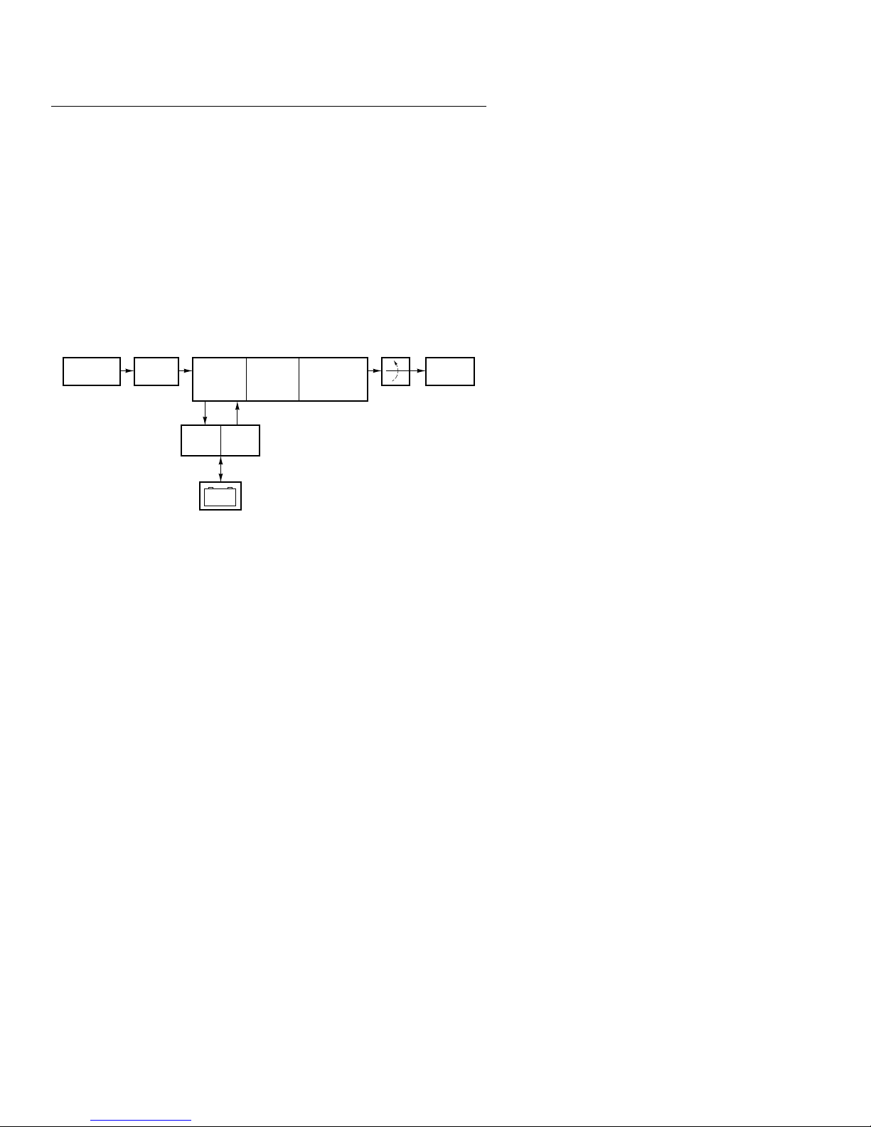
ON Series UPS: Block Diagram of
Architecture
Output
Low
Impedance
Isolating
Transformer
InverterCharger
ONBoost
Output Filter
(Virtual Kelvin
Ground)
Control
Load
Your
Computer
+–
Battery
8 ON Series User Instruction Manual
Theory of Operation
Inrush T olerance
The UPS load meter may initially display “c8”
during the computer power-up sequence due to
momentary current surges. The display returns to
“99” or less as long as the load of the running
equipment is at 100 percent or less.
Output Overload
Protection
ON Series User Instruction Manual 9
During normal operation, electronic output overload
protection is active. If the output is loaded to more
than 105 percent of the UPS rating, battery power to
the UPS is not available. The digital display for
output overload is “c8”. If the output load exceeds
125 percent, the output turns off completely after
two seconds and the digital display reads “c9”. To
reset, turn the UPS OFF, remove some of the load,
then turn the UPS ON. (For GS compliance: The
power distribution system for all models is type TN.)
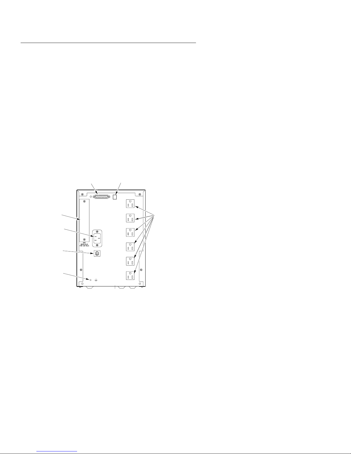
Theory of Operation
Interface Connector DIP Switches
Input Protector
A grossly overloaded UPS trips the rear panel circuit
breaker. The front panel display reads “c1”. To reset
the circuit breaker, push the button in.
• If the circuit breaker trips repeatedly following
reset, unplug the equipment from the UPS output
receptacles and reset the circuit breaker once
again.
• If operation appears to be normal, check the total
equipment load. Add your equipment to the
output one device at a time. Check the front
panel display after each device is powered ON.
• If the circuit breaker trips with nothing plugged
into the output receptacles, there may be an
internal problem with the UPS. Call ONEAC
Technical Support for assistance (refer to
page 1).
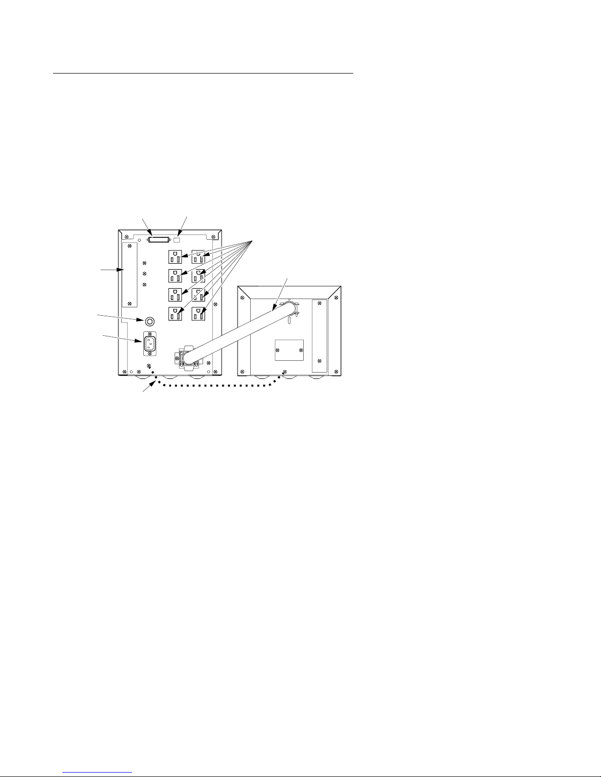
Auxiliary
Interface
Port
IEC Input
Connector
Circuit
Breaker
Environmental
Reference
Ground
Model Shown: ON900A-SN
10 ON Series User Instruction Manual
Output
Receptacles

Setup and
Installation
Setup and Installation
Inspection and
Unpacking
Previous experience with UPS operation is not
required prior to operating ON Series units.
Before shipment, this product was tested, inspected,
and found to be free of mechanical and electrical
defects. Upon receipt of your UPS, carefully
examine the packing containers for any sign of
physical damage. Notify the carrier immediately if
damage is present.
Carefully unpack the UPS. Retain the packaging
materials for reuse (refer to page 66, Return
Procedure) or dispose of the materials properly.
Once unpacked, inspect and test the unit for any
hidden damage that may have occurred in transit. If
any damage is evident, contact ONEAC’s Technical
Support Department immediately (refer to page 1) to
correct the problem.
CAUTION: Do not attach laser printers to the UPS.
A laser printer periodically draws significantly mor e
power during use and may overload the UPS.
Testing
ON Series User Instruction Manual 11
Before connecting the UPS to other equipment, plug
the UPS into an A C-po wered wall outlet and turn the
UPS ON. When selecting a location for your UPS, be
sure that the unit is near the wall outlet and is easily
accessible. After the self-tests are completed, the
digital display on the front should read “00” and the
“% LOAD” light should be on. If the digital display
reads differently, refer to System Status Codes
beginning on page 63. When the digital display reads
“00”, the UPS is ready for use.
NOTE: If the battery is not fully char ged, the digital
display may read “c4”. This condition may exist for
4 – 12 hours if a unit has been stored.
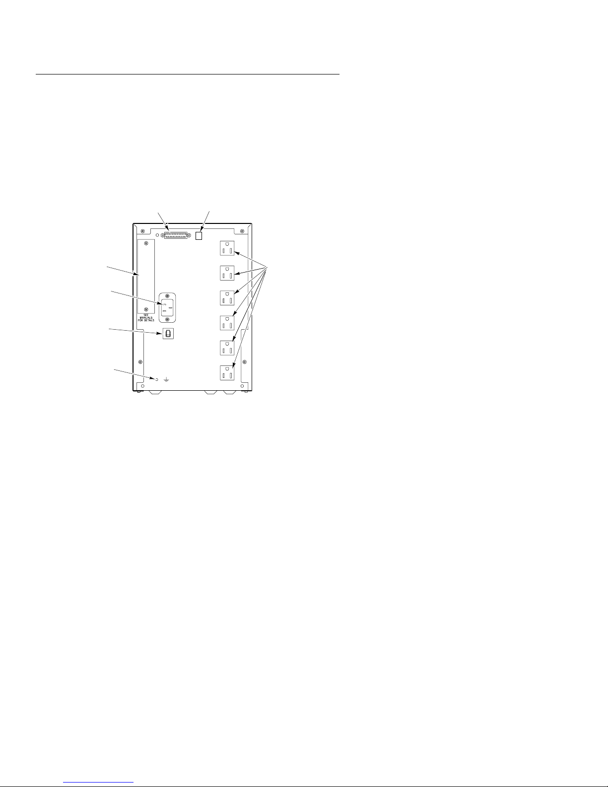
Setup and Installation
Environmental
Reference
Ground
®
Auxiliary
Interface
Port
IEC Input
Connector
Circuit
Breaker
Environmental
Reference
Ground
The UPS provides a common ground point for
system components and static protection devices;
network cable segments that require shield
grounding; static control devices such as floor mats,
table mats, static-free work benches; or any other
device that requires a reference ground connection.
For use, remove the green screw on the back panel,
attach a ground cord connector, and reinstall the
screw.
Interface Connector DIP Switches
Output
Receptacles
Model Shown: ON900A-SN
12 ON Series User Instruction Manual

Setup and Installation
Setup Precaution
Long Term
Storage
The percent of UPS capacity in use is displayed on
the front panel of the UPS. As long as the display
reads “99” or less when the AC line is present and
your equipment is running, the UPS is not
overloaded. If the front panel displays “c8” or “c9”,
the unit is overloaded. Remov e some of the load until
the front panel displays “99” or less.
Improper long-term UPS storage may damage the
UPS battery and invalidate the battery warranty.
Unplugging a UPS from its AC utility power source
for an extended period of time results in lost battery
charge. Restoration of charge to maximum capacity
requires 24 – 48 hours. For standard models, the
System code may show a “c4” for 2 – 4 hours after
utility power is restored. For extended runtime
models, the system code “c4” may show for 2 – 4
hours per battery cabinet.
To keep the battery enclosure fully charged and to
maximize the life of the battery , plug the UPS into an
outlet while it is in storage. If the UPS is stored
without power access, plug it into a po wer source for
24 hours at least once every 4 – 6 months.
ATTENTION: If the storage temperature is greater
than 30
°
C (86
°
F) plug the UPS into a power source
for 24 hours every 2 to 3 months.
ATTENTION: The UPS should not be stored at
temperatures below -15
Ventilation
ON Series User Instruction Manual 13
The ventilation requirement for standard ON Series
UPSs is 2 in. (50 mm) minimum clearance on all
sides. Rackmount units are vented at the front and
back. Side clearance is not required.
°
C (+5
°
F).

Setup and Installation
Grounding the
Unit
To eliminate shock hazard, connect the unit to a
properly grounded AC receptacle.
Before applying power , verify that the product rating
matches the available line voltage listed on the
rear-panel label.
For CE compliance, add wire between chassis
(earth) of power unit and chassis (earth) of battery
cabinet(s).
CAUTION: Interruption of the protective grounding
conductor or disconnection of the protective earth
terminal presents a potential shoc k hazard that could
result in personal injury and damage to the
equipment.
NOTE: The ON2000A requir es a 20 Amp cir cuit and
receptacle for power.
15 A 20 A
NOTE: When connecting the UPS, make sure that
the receptacle has power available and is not
controlled by a wall switch.
14 ON Series User Instruction Manual
Setup and Installation
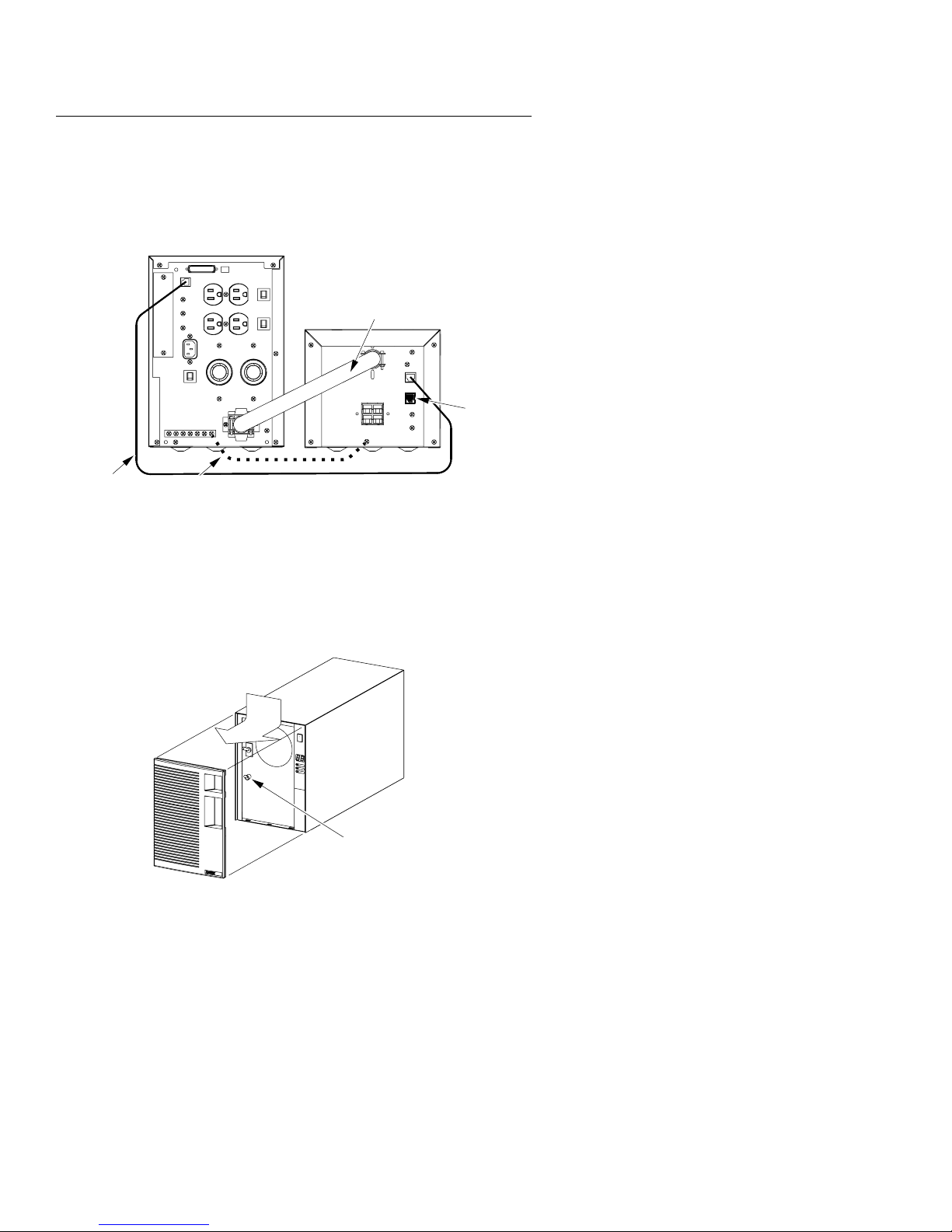
Installing
Standard
ON2000 Units
Auxiliary
Interface
Port
Circuit
Breaker
AC Line Cord
Receptacle
Interface
Connector
Place the power unit next to, or on top of, the battery
module. For CE compliance, add wire between
chassis (earth) of power unit and chassis (earth) of
battery cabinet(s). Attach the AC line cord to the
receptacle on the back panel 24
of the UPS, and then to a properly grounded AC
wall receptacle. Connect the battery power cable as
shown below. Secure the cable with screws
(supplied) at each side flange.
DIP Switches
Output
Receptacles
Battery Power
Cable
Ground
ON2000 (Standard Model)
ON Series User Instruction Manual 15
Setup and Installation
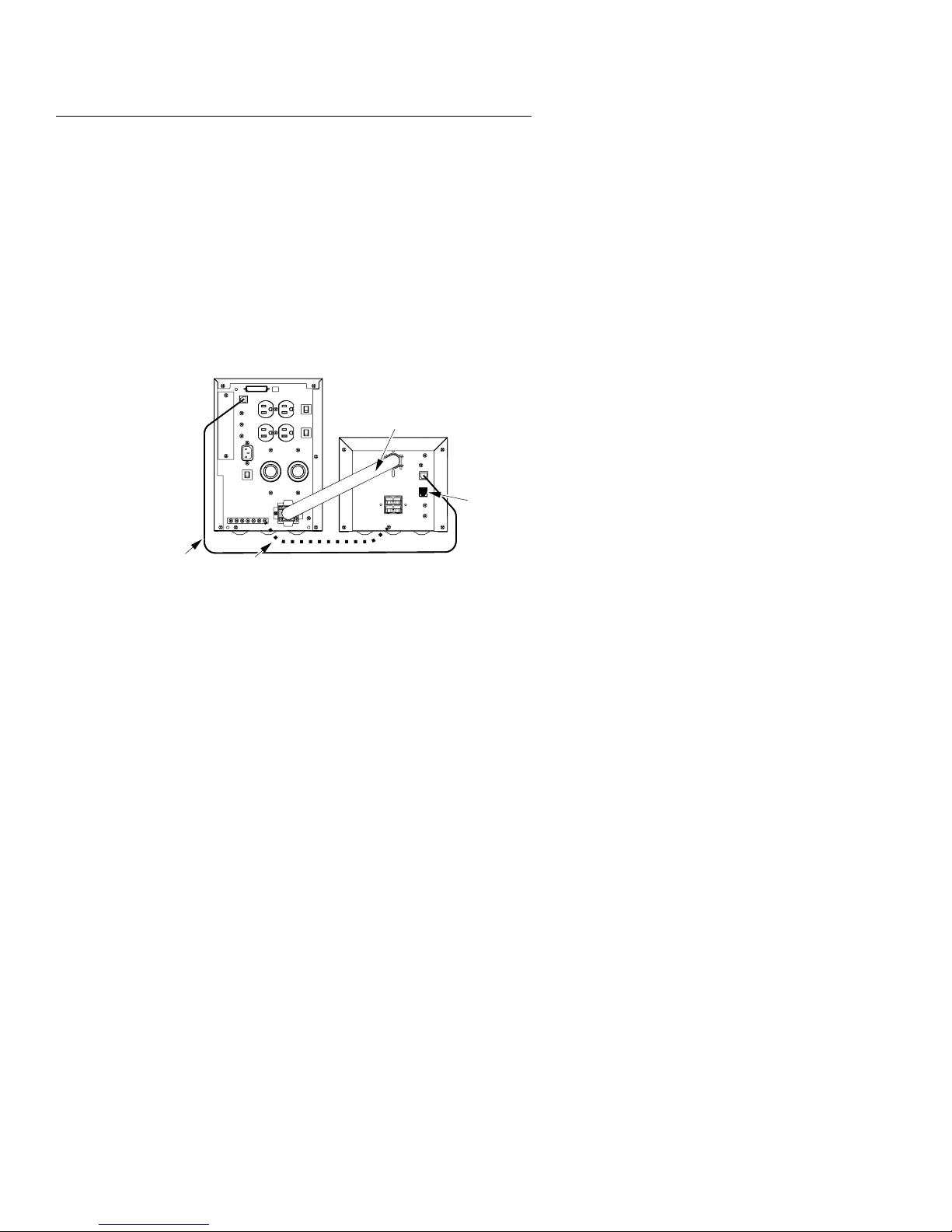
Installing
ON2200XA
Extended
Runtime Units
RJ Cable
NOTE: The ON2200XA requir es a 60 Hz, A C circuit
providing either 208, or 220 – 240 Vac.
Main
Battery Power
Cable
Battery
Unit
Terminator
Ground
Before plugging your ON2200XA into the A C input
circuit, you should test the line voltage of the circuit
to determine whether the feed is delivering 208 or
220 – 240 volts rms.
Remove the front cov er of the power unit and set the
input voltage toggle switch to the position that
matches the feed voltage. Replace the cover.
16 ON Series User Instruction Manual
Input Voltage
Selection
Switch

Setup and Installation
You are now ready to complete the installation by
following the instructions in Installing Standard
Extended Runtime Units below.
NOTE: The ON2200XA provides a variety of output
voltages as indicated in the table below:
Out Vrms
Input V olts
208 230 230 115 115
220–240 220–240 230 110–120 115
L6-30Rs
on AC
Out Vrms
L6-30Rs
On Battery
Out Vrms
5–20Rs
on AC
NOTE:Loading capacity
The ON2200XA is capable of delivering its full rated
output capacity of 1500 watts, (2200 VA) on both
220V and 110V output circuits. If all the load is
powered from the 110V circuits, the maximum total
current draw is 19 amps, limited to 15 amps on any
duplex.
Installing
Standard
Extended
Runtime Units
To install an extended runtime unit there are two or
three connections that need to be made: the battery
power cable, the RJ cable, and the ground wire.
The six-pin RJ cable allows the power unit to count
the number of battery enclosures connected. If the
connection is incorrect or incomplete, runtime
reporting and assessment of the batteries will be
inaccurate.
For CE compliance, add wire between chassis of
power unit and chassis (earth) of battery cabinet(s).
Out Vrms
5–20Rs
On Battery
ON Series User Instruction Manual 17
Setup and Installation
Connecting One Battery Enclosure
Standard and Rack-Mount Systems
1. Connect an RJ data cable (supplied with each
battery unit) from the battery unit’ s eight-pin RJ
connector (marked “IN”) to the six-pin RJ
connector on the main unit.
A terminating plug (with wire loop) is supplied
in each battery unit’s six-pin RJ connector
(marked “OUT”).
Leave it in place. The UPS
will not operate properly with the plug removed.
Main
Battery Power
Cable
Battery
Unit
T erminator
RJ Cable
Ground Wire
2. For CE compliance, add a ground wire between
chassis of power unit and chassis (earth) of
battery cabinet(s) as shown in the abov e diagram.
3. Attach the AC line cord to the receptacle on the
back panel of the UPS and then to a properly
grounded AC wall receptacle.
4. Connect the battery unit’s power cable to the
main unit. Secure the cable with screws
(supplied) at each side flange. The battery unit’s
power input is not used.
18 ON Series User Instruction Manual

Setup and Installation
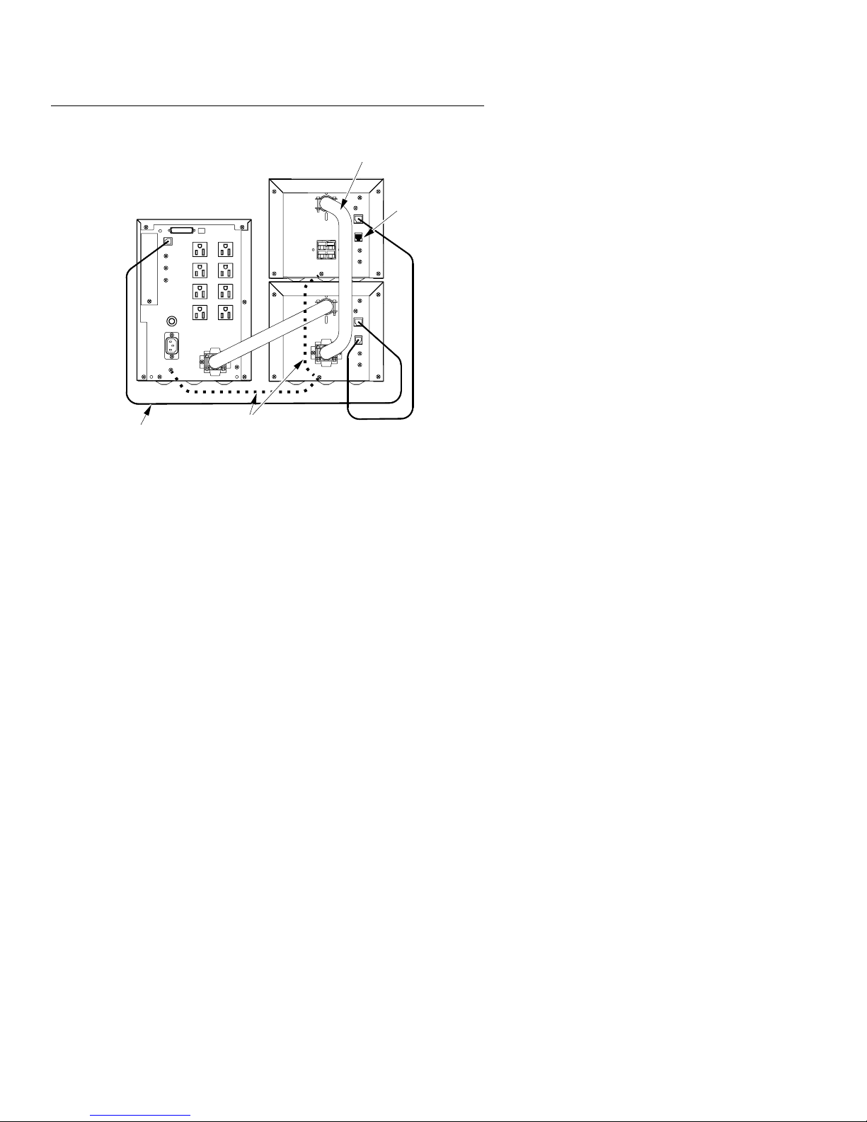
Connecting Multiple Battery
Enclosures
Standard and Rack-Mount Systems
1. Remove the terminating plug (with wire loop)
from the six-pin RJ connector on all but the last
battery unit. Set these aside. Only one
terminating plug is required for the system.
2. Connect an RJ data cable (supplied with each
battery unit) from the closest battery unit’s
eight-pin RJ connector (marked “IN”) to the
six-pin RJ connector on the main unit.
3. Connect another RJ data cable from the next
battery unit’s eight-pin RJ connector (marked
“IN”) to the closest battery unit’s six-pin RJ
connector (marked “OUT”). Continue this
process until RJ cables connect all battery units
in a “chain”.
NOTE:Leave the terminating plug installed in the
last battery unit’s six-pin RJ connector (marked
“OUT”). The UPS will not operate pr operly with the
plug removed.
4. For CE compliance, add a ground wire between
chassis of power unit and chassis (earth) of
battery cabinet(s) as shown in the following
diagram.
5. Attach the AC line cord to the receptacle on the
back panel of the UPS and then to a properly
grounded AC wall receptacle.
6. Connect the closest battery unit’ s power cable to
the main unit. Secure the cable with screws
(supplied) at each side flange.
7. Connect the next battery unit’ s power cable to the
closest battery unit’s power input. Secure the
cable with screws (supplied). Continue this
process until power cables connect all battery
units in a “chain”. The last battery unit’s power
input is not used.
ON Series User Instruction Manual 19
Setup and Installation
Battery Power
Cable
RJ Cable
Main
Ground Wire
Terminator
Battery
Units
Model Shown: ON2000XA-SN
20 ON Series User Instruction Manual

Setup and Installation
Mounting
Wallmount
Extended
Runtime Units
and Battery
Enclosures
Mount the power unit and battery enclosure(s) to a
3/4-in. plywood (minimum) backboard. Use the
enclosed four 1/4-in. x 1-in. slotted-hex,
washer-head wood screws.
1. Draw a straight, level, horizontal 8-in. line on the
backboard.
2. Mark two screw locations, on the line, 7-3/8 in.
apart.
3. Drill a 3/16-in. diameter hole at each screw
location.
4. Drive the scre ws into the backboard at the scre w
locations. Allow a 1/8-in. gap.
5. Slide the keyhole slots, located on the back of the
unit, over the screws.
6. Check to ensure that the unit is level.
7. When the unit is level, drive the remaining two
screws through the holes in the mounting tabs at
the bottom of the unit.
NOTE: When mounting the power unit and battery
enclosure, make sure that cables can reach the
connection points without twisting, pinching, or
stressing the cables or connectors.
ON Series User Instruction Manual 21

Setup and Installation
Installing
Wallmount
Extended
Runtime Units
To install an extended runtime unit there are two or
three connections that need to be made: the battery
power cable, the RJ cable, and the ground wire.
The six-pin RJ cable allows the power unit to count
the number of battery enclosures connected. If the
connection is incorrect or incomplete, runtime
reporting and assessment of the batteries will be
inaccurate.
For CE compliance, add a ground wire between
chassis of power unit and chassis (earth) of battery
cabinet(s).
Connecting One Battery Enclosure
Wall-Mount Systems
1. Connect an RJ data cable (supplied with each
battery unit) from the battery unit’ s eight-pin RJ
connector (marked “IN”) to the six-pin RJ
connector on the main unit.
A terminating plug (with wire loop) is supplied in
each battery unit’s six-pin RJ connector (marked
“OUT”). Leave it in place. The UPS will not operate
properly with the plug removed.
2. Attach the AC line cord to the receptacle on the
back panel of the UPS and then to a properly
grounded AC wall receptacle.
3. Connect a power cable (supplied with each
battery unit) from either of the battery unit’s
power connectors to the main unit. The
remaining battery unit power connector is not
used.
NOTE:On the wall mounted units, the back panel is
the bottom panel.
22 ON Series User Instruction Manual

Setup and Installation
Wallmount Extended Runtime Power Unit
RJ Connector
Auxiliary
Interface
Port
Input
Connector
Interface
Connector
IEC
DIP Switches
Circuit
Breaker
Output
Receptacles
Mate-n-Lock
Connector
Environmental
Reference
Ground
Wallmount Extended Runtime Battery Enclosure
RJ
Connectors
Out
In
Mate-n-Lock
Connectors
ON Series User Instruction Manual 23

Setup and Installation
Connecting Multiple Battery
Enclosures
NOTE:Leave the terminating plug installed in the
last battery unit’s six-pin RJ connector (marked
“OUT”). The UPS will not operate pr operly with the
plug removed.
1. Remove the terminating plug (with wire loop)
from the six-pin RJ connector on all but the last
battery unit. Set these aside. Only one
terminating plug is required for the system.
2. Connect an RJ data cable (supplied with each
battery unit) from the closest battery unit’s
eight-pin RJ connector (marked “IN”) to the
six-pin RJ connector on the main unit.
3. Connect another RJ data cable from the next
battery unit’s eight-pin RJ connector (marked
“IN”) to the closest battery unit’s six-pin RJ
connector (marked “OUT”). Continue this
process until RJ cables connect all battery units
in a “chain”.
4. For CE compliance, add a ground wire between
chassis of power unit and chassis (earth) of
battery cabinet(s) as shown in the following
diagram.
5. Attach the AC line cord to the receptacle on the
back panel of the UPS and then to a properly
grounded AC wall receptacle.
6. Connect a power cable (supplied with each
battery unit) from either of the closest battery
unit’s power connectors to the main unit.
7. Connect a power cable from the closest battery
units other power connector to either of the next
closest battery units power connectors. Continue
this process until power cables connect ALL
battery units in a “chain.” The last battery unit’s
extra connector is not used.
NOTE:On the wall mounted units, the back panel is
the bottom panel.
24 ON Series User Instruction Manual

AC Line Cord
Receptacle
Setup and Installation
Terminator
RJ
Cable
Battery
Power Cable
ON Series User Instruction Manual 25

Setup and Installation
Installing
Rackmount Units
Install Rackmount UPSs as low as possible in the
rack. Do not install the UPS near heat sources.
Model Shown: ON600-RM-SN
The Rackmount UPS draws cooling air from back to
front. If the rack has a door on the front, make sure
that there is some clearance between the vents and
the rack door.
26 ON Series User Instruction Manual

Setup and Installation
Front Panel
Features and
Controls
Once the UPS is correctly installed, the front panel
display provides all necessary operating
information. To operate an ON Series UPS:
1. Plug the unit into an AC power source.
2. Plug the load equipment into the UPS.
3. Turn the front-panel switch ON.
Power ON/OFF Switch
With the UPS plugged in, operate the ON ( | ) switch
up to supply power to the loads. The loads are
immediately powered.
T o turn OFF the UPS’s output power, press the OFF
( O ) power switch down. The UPS ON/OFF switch
can be used as a master ON/OFF switch for the
protected equipment.
NOTE:This switch controls output power only. The
unit will continue to operate the battery char ger and
control circuits even when front panel switch is in
“OFF” position.
ON Series User Instruction Manual 27

Setup and Installation
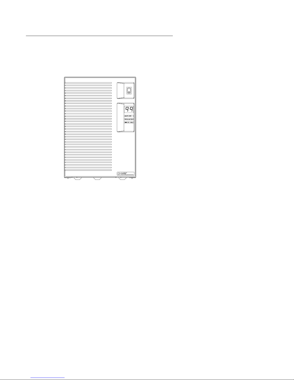
Front Panel Display
Three display lights operate in conjunction with a
digital display on the front panel to show system
status:
When the “% LOAD” light is on, the digital display shows the
1 % LOAD
2 % BATTERY
3 SYS. CODE
percentage of capacity in use, in one percent increments,
with full load displayed as “99”.
When the “% BATTERY” light is on, the digital display
indicates the relative amount of battery runtime available, in
five percent increments, during an AC line power failure.
When the “SYS. CODE” light is on, an unusual condition
exists. Refer to pages 63 and 64 for the System Status Code
labels included in the rear of this manual to interpret the
reading.
% LOAD
% BATTERY
SYS. CODE
1
2
3
NOTE:Place the enclosed peel-n-stick label
(located on the warranty re gistration car d on the last
page of this manual) on or near the UPS for future
reference. This label provides a quick reference for
interpretation of the system status codes.
28 ON Series User Instruction Manual

Setup and Installation
Back Panel DIP
Switch Settings
DIP Switch Settings
DIP switches are located on the rear panel of the
UPS.
ON
1 2 3 4
OFF
The following table describes the switch settings and
their corresponding configurations.
Table 1. DIP Switches
Switch Description Down (Off) Up (On)
1 Interface port configuration ADVANCED BASIC
2 Interface port baud rate 1200 9600
3* UPS frequency 50 Hz 60 Hz
4 Reserved
Switches 1 and 2: Units are shipped with the
interface preset to “Advanced” and “9600” to
support ONEAC’s most popular UPS monitoring
software accessory kits. Follow the special
instructions in the accessory kit, or refer to
Appendix A for information on supporting third
party interface software.
*Switch 3: This switch is only applicable to the
50/60Hz switchable models. Its setting has no affect
on the 120V, 60Hz “A” models.
ON Series User Instruction Manual 29

Features and Specifications
Features and
Specifications
Standard Rackmount
ON400
ON600
ON900
ON1300
ON2000
Family Overview:
Standard and Extended Runtime
Models
Standard
Extended
Runtime
Wall Mount
Extended
Runtime
Rackmount
Extended
Runtime
ON2200
30 ON Series User Instruction Manual

The ON Series product family was designed for
various power environments. Each part number
includes a letter. This letter identifies the power
environment. Please specify the part number and
letter when ordering
• 120 or 208/240V, 60Hz applications=A.
Example: ON400A-SN.
• 230V, 50/60Hz applications=I.
Example: ON400I-SN.
• 120V, 50/60Hz applications (which are
110 – 120V nominal)=J.
Example: ON400J-SN.
NOTE:Two models, the ON400 and ON900, are
offered for the 120V, 50/60Hz power environment.
For information on models operating in power
environments below 110V, refer to Appendix B:
Operating in Power Environments Below 110V
Nominal on page 68.
Features Full output isolation and power
conditioning
Ground
Five-year warranty on power and
control systems
Two-year warranty on battery enclosure
Sinusoidal inverter wave form, load
regulated
Intelligent battery management system:
• Battery condition monitoring and status alerts
• Low battery indication
• ONBoost, low line voltage compensation
without battery depletion
• Inverter shutdown control
• Hot Swap, user replaceable battery enclosure
• Battery charge indicator
with Virtual Kelvin
®
output filtering
Features
ON Series User Instruction Manual 31

Features
Agency approvals: UL, cUL, FCC, GS,
CE Approved
System intelligence and
communications:
• Basic Interface supports Novell, B ANYAN, Lan
Server, and Windows NT
• Advanced RS-232 UPS control language support
information required for IETF UPS MIB
conformance
• Auxiliary interface expansion port
• Programmable switchover thresholds
• Intelligent runtime estimates
• Unit identification stored in memory for remote
asset management
• Digital load meter with output overload
protection and recovery indication
Options The ON Series units can be customized to suit your
particular computing environment. Special types of
receptacles, such as hospital grade and country
specific, are available.
Auxiliary Interface Port
The auxiliary interface port is located on the back
panel of the UPS. ONEAC of fers optional interfaces
which may be plugged into this port to connect it to
a computer system or network. Refer to page 54 for
special notes on installing interface cards. See
page 51 for available accessories.
Ethernet SNMP Interface Card
An SNMP interface card is av ailable for individuals
who need direct access and control of every critical
device on the network through a common
SNMP-based management console. A user can
receive notifications of conditions that require/merit
attention. ONEAC’s SNMP solution also enables
remote control, remote testing, and information
retrieval on networked ON Series UPSs.
32 ON Series User Instruction Manual

Features
Physical and
Electrical
Specifications
Performance Characteristics For All
Models (Tables 2 – 5)
Surge voltage withstand capability: ANSI/IEEE
C62.41 Category A&B, 6kV/200 & 500 Amp, 100
kHz Ringwave
Surge voltage let-through (max): less than 10V
Normal mode (L-N), less than 0.5 V Common mode
(N-G) when subjected to 6kV ANSI/IEEE C62.41
Cat. A
Normal & common mode clamping response
time: instantaneous
Transfer time (typical/max): < 3.0 / 3.5
milliseconds
ONBoost™: boosts output voltage 11% abov e input
voltage if between -21% & -15% of nominal
Load power factor range (crest factor): UPS .65 to
1.0 (3) — will support loads rated 0.5 to 1.0 (<5)
Inverter waveform total harmonic distortion:
< 3% THD Sinewave, no load, typical
Environmental Considerations: Ambient
operation is 10,000 feet (3,000 meters) maximum
elevation, 0 – 95% humidity non-condensing, and
32 – 104°F (0 – 40°C)
Batteries: sealed, maintenance-free lead acid with a
3 – 6 year typical lifetime
Recharge time to 60% available capacity: 4 hours
per battery cabinet
All units have temperature sensitive chargers and
provide thermal isolation for battery pack.
ON Series User Instruction Manual 33

Features
Table 2A. Standard “A” Unit Specifications
ON400 ON600 ON900 ON1300 ON2000
Input connector IEC 320 IEC 320/C20
Output sockets: NEMA 5-15R
for 120V
120V units include 6-foot detachable input cord with a 5-15P plug, except for the
ON2000 which has a 5-20P plug. Other plugs and sockets are available on request.
Maximum Dimensions-inches
(cm): (H)
Net weight-lbs. (kg.)
Shipping weight-lbs. (kg.)
Nominal input voltage: 120Vac 60Hz
On battery output voltage: Sinewave 120Vac
Maximum capacity (volt-amps)
(watts)
Batteries: Sealed,
maintenance-free lead acid,
3–6 yr. typical life
Efficiency (%) on utility, 100%
load
4 4 6 8 8
7.5
(19.1)
(W)
8.5
(21.6)
(D)
15.5
(39.4)
30 (14)
35 (16)
400
280
Two,
12V,
4AH
90% 83% 83% 87% 83%
7.5
(19.1)
8.5
(21.6)
18.5
(47.0)
41 (18)
46 (21)
600
400
Two,
12V,
7AH
12
(30.5)
8.5
(21.6)
18.5
(47.0)
59 (26)
64 (29)
900
600
Four,
6V,
10AH
12
(30.5)
8.5
(21.6)
21
(53.3)
78 (35)
83 (37)
1300
900
Two,
12V,
17AH
Power Battery
12
(30.5)
(21.6)
(47.0)
58 (26)
63 (28)
8.5
18.5
1850
1300
Four, 12V,
17AH
(19.1)
(21.6)
18.5
(47.0)
70 (32)
75 (34)
7.5
8.5
34 ON Series User Instruction Manual

Features
Table 2I. Standard “I” and “J” Unit Specifications
ON400 ON600 ON900 ON1300 ON2000
Input connector IEC 320
Output sockets: IEC 320
female for 230V
230V units include IEC320 M/F detachable output cord(s). Other plugs and sockets
are available on request.
Maximum Dimensions-inches
(cm):
Net weight-lbs. (kg.)
Shipping weight-lbs. (kg.)
Nominal input voltage:
On battery output voltage: "I" models: 230Vac "J" models: 120Vac
Maximum capacity (volt-amps)
(watts)
Batteries: Sealed,
maintenance-free lead acid,
3–6 yr. typical life
Efficiency (%) on utility, 100%
load
4448 8
(H)
7.5
(19.1)
(W)
8.5
(21.6)
(D)
15.5
(39.4)
33 (15)
38 (17)
400
280
Two,
12V,
4AH
90% 83% 83% 87% 83%
7.5
(19.1)
8.5
(21.6)
18.5
(47.0)
44 (20)
50 (23)
“I” models: 230Vac 50/60Hz “J” models:
600
400
Two,
12V,
7AH
12
(30.5)
8.5
(21.6)
18.5
(47.0)
64 (29)
69 (31)
120Vac 50/60Hz
900
600
Four,
6V,
10AH
12
(30.5)
8.5
(21.6)
21
(53.3)
88 (40)
92 (41)
1300
900
Two,
12V,
17AH
Power Battery
12
(30.5)
(21.6)
(47.0)
60 (27)
66 (31)
8.5
18.5*
2000
1400
Four, 12V,
17AH
(19.1)
(21.6)
18.5*
(47.0)
70 (32)
75 (34)
7.5
8.5
* Length of chassis, allow an additional 10 in. (25.40 cm.) at rear of unit to
accommodate external battery cable connection.
ON Series User Instruction Manual 35

Features
Table 3A. Rackmount "A" Unit Specifications
ON600 ON900 ON1300 ON2000
Input connector IEC 320/C20 IEC 320/C20
Output sockets: NEMA 5-15R for 120V 6 6 8 8
120V units include 6-foot detachable input cord with a 5-15P plug, except for the
ON2000 which has a 5-20P plug. Other plugs and sockets are available on request.
Power Battery
Maximum Dimensions-inches (cm): (H)
Net weight-lbs. (kg.)
Shipping weight-lbs. (kg.)
Height 4U 4U 6U 6U 6U
Nominal input voltage: 120Vac 60Hz
On battery output voltage: Sinewave 120Vac
Maximum capacity (volts-amps)
(watts)
Batteries: Sealed, maintenance-free
lead acid, 3–6 yr. typical life
Efficiency (%) on utility, 100% load 83% 83% 87% 83%
(W)
(D)
6.9
(17.5)
19
(48.3)
15
(38.1)
46 (21)
50 (23)
600
400
Two,
12V,
7AH
6.9
(17.5)
19
(48.3)
15
(38.1)
65 (30)
69 (31)
900
600
Four, 6V,
10AH
10.5
(26.7)
19
(48.3)
15
(38.1)
92 (41)
101 (46)
1300
900
Two,
12V ,
17AH
10.5
(26.7)
19
(48.3)
15*
(38.1)
66 (30)
72 (33)
1850
1300
Four, 12V,
17AH
(26.7)
(48.3)
(22.9)
76 (35)
82 (37)
10.5
19
9*
* Length of chassis, allow an additional 10 in. (25.40 cm.) at rear of unit to
accommodate external battery cable connection.
36 ON Series User Instruction Manual

Features
Table 3I. Rackmount "I" Unit Specifications
ON600 ON900 ON1300 ON2000
Input connector IEC320
Output sockets: IEC 320 female for
230V
230V units include IEC320 M/F detachable output cord(s). Other plugs and sockets
are available on request.
Maximum Dimensions-inches (cm): (H)
Net weight-lbs. (kg.)
Shipping weight-lbs. (kg.)
Height 4U 4U 6U 6U 6U
Nominal input voltage: 230Vac 50/60Hz
On battery output voltage: Sinewave 230Vac
Maximum capacity (volts-amps)
(watts)
Batteries: Sealed, maintenance-free
lead acid, 3–6 yr. typical life
Efficiency (%) on utility, 100% load 83% 83% 87% 83%
4 4 8 8
(W)
(D)
6.9
(17.5)
19
(48.3)
15
(38.1)
48 (22)
52 (24)
600
400
Two,
12V,
7AH
6.9
(17.5)
19
(48.3)
15
(38.1)
68 (31)
73 (33)
900
600
Four, 6V,
10AH
10.5
(26.7)
19
(48.3)
15
(38.1)
101 (45)
108 (49)
1300
900
Two,
12V ,
17AH
Power Battery
10.5
10.5
(26.7)
(26.7)
19
19
(48.3)
(48.3)
15*
(38.1)
(22.9)
66 (30)
76 (35)
72 (33)
82 (37)
2000
1400
Four, 12V,
17AH
9*
* Length of chassis, allow an additional 10 in. (25.40 cm.) at rear of unit to
accommodate external battery cable connection.
ON Series User Instruction Manual 37

Features
Table 4A. Standard "A" Unit Extended Runtime Specifications
ON600 ON900 ON2000 ON2200
Input connector IEC 320 IEC 320/C20
Output sockets: NEMA 5-15R for
120V:
NEMA 5-20R for 115V:
NEMA L6-30R for 230V:
120V units include 6-foot
detachable input cord with:
Maximum Dimensions-inches (cm):
Net weight-lbs. (kg.)
Shipping weight-lbs. (kg.)
Nominal input voltage 120Vac 60Hz
On battery output voltage Sinewave 120Vac
Maximum capacity (volt-amps)
(watts)
Batteries: Sealed, maintenance-free lead acid, 3–6 yr. typical life
Efficiency (%) on utility, 100% load 83% 83% 83% 88%
(H)
(W)
(D)
4
-
-
5-15P Plug
7.5
(19.1)
8.5
(21.6)
18.5*
(47.0)
30 (14)
35 (16)
600
400
6
-
-
12
(30.5)
8.5
(21.6)
18.5*
(47.0)
45 (20)
50 (23)
900
600
8
-
-
5-20P
Plug
12
(30.5)
8.5
(21.6)
18.5*
(47.0)
58 (26)
63 (28)
1850
1300
L6-30P
(30.5)
(21.6)
21.5*
(54.6)
77 (35)
82 (37)
208Vac or
220①–
240Vac
Sinewave:
115Vac
2200
1500
4
2
Plug
12
8.5
230/
①
External
Battery
Cabinet
for All
Units
7.5
(19.1)
8.5
(21.6)
18.5*
(47.0)
70 (32)
75 (34)
Four,
12V,
17AH
* Length of chassis, allow an additional 10 in. (25.40 cm.) at rear of unit to
accommodate external battery cable connection.
①
See page 17 for details on input and output voltages under various conditions.
38 ON Series User Instruction Manual

Table 4I. Standard "I" Unit Extended Runtime Specifications
ON600 ON900 ON2000
Input connector IEC 320
Output sockets: IEC 320 female for 230V 4 8 8
230V units include IEC320 M/F detachable output cord(s). Other plugs and
sockets are available on request.
Maximum Dimensions-inches (cm)): (H)
Net weight-lbs. (kg.)
Shipping weight-lbs. (kg.)
Nominal input voltage: 230Vac 50/60Hz
On battery output voltage: Sinewave 120VAC/230Vac
Maximum capacity for 230V
(volt-amps, watts)
Batteries:
Efficiency (%) on utility, 100% load 83% 83% 83%
7.5
(19.1)
(W)
8.5
(21.6)
(D)
18.5*
(47.0)
34 (16)
39 (17)
600
400
Sealed, maintenance-free
lead acid, 3–6 yr. typical
12
(30.5)
8.5
(21.6)
18.5*
(47.0)
50 (23)
55 (26)
900
600
life
12
(30.5)
8.5
(21.6)
18.5*
(47.0)
61 (27)
66 (29)
2000
1400
Features
External
Battery
Cabinet
for All
Units
7.5
(19.1)
8.5
(21.6)
18.5*
(47.0)
70 (32)
75 (34)
Four,
12V,
17AH
* Length of chassis, allow an additional 10 in. (25.40 cm.) at rear of unit to
accommodate external battery cable connection.
ON Series User Instruction Manual 39

Features
Table 5A. Wall Mount "A" Unit Extended Runtime Specifications
ON400 ON600
Input connector IEC320
Output sockets: NEMA 5-15R for 120V 4 4
120V units include 6-foot detachable input cord with a 5-15P plug.
Maximum Dimensions-inches (cm): (H)
Net weight-lbs. (kg.)
Shipping weight-lbs. (kg.)
Nominal input voltage 120Vac 60Hz
On battery output voltage Sinewave 120Vac
Maximum capacity (volt-amps):
(watts):
Batteries: Sealed, maintenance-free lead acid, 3–6 yr. typical life
Efficiency (%) on utility, 100% load 90% 83%
(W)
(D)
15
(38.1)
8.5
(21.6)
9
(22.9)
25 (11)
30 (14)
400
280
15
(38.1)
8.5
(21.6)
(22.9)
29 (13)
34 (15)
600
400
External
Battery
Cabinet
for All
Units
7.5
(19.1)
8.5
(21.6)
9
9
(22.9)
35 (16)
40 (18)
Two,
12V,
17AH
40 ON Series User Instruction Manual

Features
Table 5I. Wall Mount "I" Unit Extended Runtime Specifications
External
Battery
15
8.5
9
600
400
Cabinet
for All
Units
7.5
(19.1)
8.5
(21.6)
(22.9)
35 (16)
40 (18)
Two,
12V,
17AH
ON400 ON600
Input connector IEC 320 female
Output sockets: IEC 320 female 4 4
230V units include IEC 320 M/F detachable output cord(s). Other plugs and sockets
are available on request.
Maximum Dimensions-inches (cm): (H)
Net weight-lbs. (kg.)
Shipping weight-lbs. (kg.)
Nominal input voltage 230Vac 50/60Hz
On battery output voltage Sinewave 230Vac
Maximum capacity (volt-amps):
(watts):
Batteries: Sealed, maintenance-free lead acid, 3–6 yr. typical life
Efficiency (%) on utility, 100% load 90% 83%
(W)
(D)
15
(38.1)
8.5
(21.6)
9
(22.9)
28 (13)
33 (15)
400
280
(38.1)
(21.6)
(22.9)
33 (15)
38 (17)
9
ON Series User Instruction Manual 41

Features
Runtime
Estimates
Table 6. Standard and Rackmount Unit Runtimes
Percent of Capacity ON400 ON600 ON900 ON1300
Runtimes are expressed in hours:minutes.
Typical runtimes based on fully charged, new batteries operating under typical load conditions.
Runtimes are affected by battery age, ambient temperature, site specific UPS usage patterns and
load characteristics.
Your actual runtime may be different.
10 1:33 1:45 1:59 2:32 3:00 2:48
20 0:43 0:52 0:58 1:11 1:36 1:29
30 0:27 0:34 0:37 0:45 1:05 1:00
40 0:19 0:25 0:27 0:33 0:49 0:45
50 0:15 0:20 0:21 0:25 0:39 0:36
60 0:12 0:17 0:17 0:20 0:32 0:29
70 0:10 0:14 0:14 0:17 0:27 0:24
80 0:09 0:13 0:12 0:14 0:23 0:21
90 0:08 0:11 0:10 0:12 0:20 0:18
100 0:07 0:10 0:09 0:11 0:17 0:15
ON2000
(A)
ON2000
(I)
NOTE:Runtimes in the above chart are based on
tests using 0.65 PF switched mode power supply.
42 ON Series User Instruction Manual

Table 7. ON600 Extended Runtime Unit Runtimes
Features
Percent of Capacity
12345678
Runtimes are expressed in hours:minutes.
Typical runtimes based on fully charged, new batteries operating under typical load conditions.
Times estimated assuming a switch mode power supply with a power factor of 0.65.
Runtimes are affected by battery age, ambient temperature, site specific UPS usage patterns and
load characteristics.
15 6:16 11:48
20 5:15 10:06 - - ---30 3:50 7:39 11:54
40 2:55 6:01 9:24 - ---50 2:18 4:54 7:40 10:52
60 1:52 4:07 6:27 9:07 ---70 1:34 3:33 5:33 7:51 9:53 80 1:21 3:08 4:54 6:53 8:39 - - 90 1:11 2:48 4:23 6:10 7:43 9:24 -
100 1:04 2:34 3:60 5:36 6:58 8:28 - -
Number of Battery Enclosures
NOTE:Runtimes shown are based on calculated
values.
ON Series User Instruction Manual 43

Features
Table 8. ON900 Extended Runtime Unit Runtimes
Percent of Capacity
12345678
Runtimes are expressed in hours:minutes.
Typical runtimes based on fully charged, new batteries operating under typical load conditions.
Times estimated assuming a switch mode power supply with a power factor of 0.65.
Runtimes are affected by battery age, ambient temperature, site specific UPS usage patterns and
load characteristics.
10 6:16 11:48
20 3:50 7:39 11:54 - ---30 2:34 5:24 8:27
40 1:52 4:07 6:27 9:07 ---50 1:27 3:19 5:12 7:20 9:14
60 1:11 2:48 4:23 6:10 7:43 9:24 - 70 1:01 2:27 3:50 5:21 6:39 8:05 80 0:53 2:12 3:25 4:47 5:53 7:06 8:32 90 0:47 2:01 3:07 4:20 5:17 6:20 7:39 9:07
100 0:42 1:51 2:51 3:59 4:47 5:43 6:55 8:16
Number of Battery Enclosures
NOTE:Runtimes shown are based on calculated
values.
44 ON Series User Instruction Manual

Table 9A. ON2000 A Extended Runtime Unit Runtimes
Features
Percent of Capacity
12345678
Runtimes are expressed in hours:minutes.
Typical runtimes based on fully charged, new batteries operating under typical load conditions.
Times estimated assuming a switch mode power supply with a power factor of 0.65.
Runtimes are affected by battery age, ambient temperature, site specific UPS usage patterns and
load characteristics.
10 3:44 7:29 11:39 16:30
20 1:49 4:00 6:17 8:53 ---30 1:09 2:44 4:17 6:00 7:31 9:09 40 0:51 2:10 3:21 4:40 5:44 6:55 8:19 50 0:41 1:49 2:47 3:53 4:40 5:34 6:44 8:04
60 0:34 1:32 2:21 3:18 3:52 4:33 5:32 6:42
70 0:27 1:16 1:56 2:47 3:12 3:42 4:32 5:33
80 0:22 1:02 1:34 2:19 2:37 2:66 3:40 4:34
90 0:18 0:49 1:16 1:56 2:09 2:28 3:02 3:48
100 0:16 0:41 1:03 1:39 1:52 2:09 2:39 3:20
Number of Battery Enclosures
NOTE:Runtimes shown are based on calculated
values.
ON Series User Instruction Manual 45

Features
Table 9I. ON2000 I Extended Runtime Unit Runtimes
Percent of Capacity
12345678
Runtimes are expressed in hours:minutes.
Typical runtimes based on fully charged, new batteries operating under typical load conditions.
Times estimated assuming a switch mode power supply with a power factor of 0.65.
Runtimes are affected by battery age, ambient temperature, site specific UPS usage patterns and
load characteristics.
10 3:29 7:02 10:57 20 1:40 3:43 5:49 8:14 ---30 1:00 1:54 3:60 5:36 6:58 8:28 40 0:48 2:02 3:09 4:23 5:21 6:25 7:44 9:13
50 0:38 1:42 2:36 3:38 4:20 5:07 6:13 7:28
60 0:30 1:24 2:08 3:03 3:32 4:07 5:02 6:07
70 0:24 1:08 1:43 2:31 2:51 3:17 4:01 4:58
80 0:19 0:53 1:21 2:03 2:18 2:38 3:14 4:02
90 0:17 0:43 1:06 1:43 1:55 2:13 2:44 3:26
100 0:17 0:37 0:59 1:34 1:47 2:06 2:37 3:15
Number of Battery Enclosures
NOTE:Runtimes shown are based on calculated
values.
46 ON Series User Instruction Manual

Table 9. ON2200 Extended Runtime Unit Runtimes
Features
Percent of Capacity
12345678
Runtimes are expressed in hours:minutes.
Typical runtimes based on fully charged, new batteries operating under typical load conditions.
Times estimated assuming a switch mode supply with a power factor of 0.65.
Runtimes are affected by battery age, ambient temperature, site specific UPS usage patterns and
load characteristics.
10 3:10 6:29 10:08 20 1:30 3:23 5:19 7:30 9:26 - - 30 0:58 2:22 3:41 5:09 6:22 7:43 9:15
40 0:43 1:53 2:54 4:03 4:54 5:51 7:04 50 0:34 1:33 2:22 3:20 3:55 4:36 5:36 6:46
60 0:27 1:14 1:53 2:43 3:07 3:36 4:24 5:24
70 0:21 0:57 1:27 2:11 2:27 2:48 3:26 4:17
80 0:17 0:44 1:08 1:46 1:59 2:17 2:48 3:31
90 0:17 0:38 1:00 1:34 1:47 2:06 2:36 3:15
100 0:13 0:28 0:45 1:16 1:26 1:41 2:00 2:40
Number of Battery Enclosures
NOTE:Runtimes shown are based on calculated
values.
ON Series User Instruction Manual 47

Features
Table 10. ON400 Wall Mount Extended Runtime Unit Runtimes
Percent of Capacity
12345678
Runtimes are expressed in hours:minutes.
Typical runtimes based on fully charged, new batteries operating under typical load conditions.
Times estimated assuming a switch mode supply with a power factor of 0.65.
Runtimes are affected by battery age, ambient temperature, site specific UPS usage patterns and
load characteristics.
10 5:58 12:33 - - ---20 3:48 7:54 11:42
30 2:51 5:53 8:52 - ---40 2:16 4:43 7:11 10:02 ---50 1:53 3:56 6:03 8:25 10:24
60 1:36 3:21 5:13 7:14 8:55 - - 70 1:22 2:54 4:34 6:20 7:47 9:30
80 1:12 2:33 4:03 5:36 6:52 8:20 - 90 1:03 2:15 3:38 5:00 6:01 7:22 8:52
100 0:55 2:00 3:16 4:29 5:29 6:33 7:54 9:05
Number of Battery Enclosures
NOTE:Runtimes shown are based on calculated
values.
48 ON Series User Instruction Manual

Table 11. ON600 Wall Mount Extended Runtime Unit Runtimes
Features
Percent of Capacity
12345678
Runtimes are expressed in hours:minutes.
Typical runtimes based on fully charged, new batteries operating under typical load conditions.
Times estimated assuming a switch mode supply with a power factor of 0.65.
Runtimes are affected by battery age, ambient temperature, site specific UPS usage patterns and
load characteristics.
15 3:30 7:16 10:49
20 2:51 5:53 8:52 12:25 15:24 19:25 23:29 27:06
30 2:04 4:17 6:34 9:09 11:19
40 1:36 3:21 5:13 7:14 8:55 10:59 13:12 15:08
50 1:17 2:43 4:18 5:57 7:18 8:53 10:41
60 1:03 2:15 3:38 5:00 6:07 7:22 8:52 10:10
70 0:52 1:54 3:06 4:16 5:12 6:11 7:28 8:36
80 0:43 1:37 2:41 3:41 4:28 5:15 6:22 7:20
90 0:36 1:23 2:21 3:12 3:52 4:29 5:27 6:19
100 0:29 1:11 2:03 2:47 3:22 3:50 4:42 5:28
Number of Battery Enclosures
NOTE:Runtimes shown are based on calculated
values.
ON Series User Instruction Manual 49

Features
Interface
Specifications
Pin # Signal
1 Low battery – normally open
2Rx
3Tx
5 Line fail – RS-232 static levels
7 Signal ground
8 Low battery – RS-232 static levels
10 Line fail – normally open
11 Common for simulated relay closures
18 Line fail – normally closed
20 Shutdown (to UPS)
25 Low Battery – normally closed
For the RS-232 advanced interface port, pins 2 and 3
are receive and transmit, respecti vely , and pin 7 is the
signal ground.
Pins 5 and 8 are RS-232 static levels (typically
+/-12V DC) indicate a “not true” condition (e.g., line
fail = -12 indicates that the line has not failed). +12V
DC indicates a “true” condition (e.g., line fail = +12
indicates that the line has failed).
Pins 1, 10, 18, and 25 (simulated relay closures) are
open collector transistor outputs which must be
pulled up to a common reference supply no greater
than +40V DC (See Accessories on page 53 for
Isolated Contacts Interface Card). The transistors are
NPN type 2N2222A capable of a maximum
noninductive load of 25mA DC. Pin 11 is the
common for all of the relay closure pins and is
connected to the UPS chassis ground.
Pin 20 is used to shut down the UPS when it is
operating on battery . A positive signal (3 to 24V DC)
with respect to pin 7 shuts down the UPS. A signal at
or below ground allows the UPS to keep running.
The shell of the interface connector is connected to
the UPS chassis ground.
50 ON Series User Instruction Manual

Accessories
Accessories
UPS Monitoring
Interfaces
UPS Monitoring
Software
ONEAC UPS monitoring interfaces are powerful
network management tools. They enhance systems
fault tolerance by providing automatic shutdo wn and
restart, and allow network managers to access vital
power and UPS status information. Basic interfacing
provides signals to shutdown Lan Manager, Lan
Server, and Windows NT environments.
MopUPS® for Netware
MopUPS® provides unattended system shutdown
capability for NetW are and operating environments.
It offers remote pager capability, a GUI-based
monitoring utility , and can broadcast alert conditions
that are logged into the System Error Log file.
MopUPS/RM advanced software provides all
features of MopUPS
system error messages. MopUPS/RM also provides
multiple server support to execute unattended
shutdown of two servers sharing a single UPS and
local access to remote servers or workstations
running MopUPS/RM.
®
plus the ability to review
MopUPS for Windows NT
MopUPS installs as a Service under W indo ws NT. It
constantly monitors your UPS and gracefully shuts
down the NT operating system in the event of a
prolonged power outage. An intuitive GUI interface
steps you through configuration of various automatic
event responses such as network, e-mail and pager
alerts, event logging and command file e xecution. An
integrated utility lets you view UPS front panel
information and configure UPS operating
parameters from anywhere on your network.
ON Series User Instruction Manual 51

Accessories
MopUPS for UNIX
MopUPS for UNIX provides automatic system
shutdown and status code messaging capability in
UNIX environments, including SCO, UnixWare,
Sun Solaris, IBM-AIX, HP-UX, NCR, SGI, Digital
UNIX, and Motorola System V/88.
ChangeUPS™ (Windows NT, 95 and
3.11)
ChangeUPS is an intuitive, user friendly utility that
enables you to view real time changes in your po wer
environments and change how your ON UPS
responds to changes in the environment (includes
complete online documentation).
The Main screen provides easy viewing and
interpretation of all front panel displays, product
identifiers, and line voltage statistics.
A Configuration Wizard walks through the
configurable options with ample context-sensitive
help — also allows one button reset to factory
defaults.
52 ON Series User Instruction Manual

Accessories
ONEPLUS™ Multi-Server “Y” Cable
Accessory
ONEPlus “Y” cable accessory kit allows the sharing
of communications from a single ON UPS, to initiate
unattended system shutdown sequences on two or
more servers when AC power fails and the servers
are operating from UPS battery power.
Isolated Contacts Interface Card
This optional interface card provides an isolated,
Form C contact closure signal mechanism, for
systems not compatible with the simulated contact
closures described on page 50. Unit must be set to
Basic communications mode to operate the Isolated
Contacts Interface card. See page 29.
SNMP Network Interface Card
For integrated, in-band manageability of dedicated
communications switching systems, the SNMP
interface card with SNMP-based network
management utilities supports in-band monitoring of
remote UPSs over wide-area TCP/IP networks.
SNMP interface cards house the UPS agent ethernet
controller. Both netw ork and RS-232 ports are activ e
concurrently allowing in-band SNMP-based
monitoring, and local monitoring/auto shutdown of
CPUs running MopUPS or MopUPS for UNIX.
When attached to a modem, the interface port
enables remote monitoring and Agent configuration.
An embedded SNMP Agent (MIB II compliant)
supports Subset, Basic, and Advanced compliance
groups defined in the May 1994 Internet Proposed
Standard UPS MIB.
The ethernet card has an RJ-45 connector for
10BaseT ethernet networks.
ON Series User Instruction Manual 53

Accessories
Installing and
Removing
Accessory
Interface Cards
T o install an optional interface card in an ON Series
UPS:
1. Shut down all UPS-powered systems. Turn the
UPS OFF and unplug it.
2. Identify the interface port on the back panel of
the UPS. Remove the plate if the UPS does not
have an interface card. Set the tw o screws aside.
The plate will not be used.
NOTE:This port may alr eady have an interface card
in it. If so, carefully remove it to make room for the
new interface card.
3. Carefully slide the interface card into the UPS
guide rails. Reinstall the plate screws.
54 ON Series User Instruction Manual

Battery Considerations
4. Refer to specific instructions provided in the
Accessory Kit.
5. Plug the UPS in and turn it ON.
NOTE:All ONEAC interfaces are designed to
connect to signaling systems which comply with
National Electrical Code Class 2 limits.
Battery
Considerations
Battery
Maintenance
Ordering New
Batteries
The UPS must be adequately cooled to prevent
system overheating and enhance battery life. The ON
Series UPSs must be installed with a minimum 2 in.
(50 mm) clearance on all sides. Do not place other
equipment or supplies on top of the UPS.
To preserve the performance and warranty of your
ON Series UPS, use only original equipment
replacement batteries.
ATTENTION:The batteries in this UPS are
recyclable. Dispose of the batteries properly.
Customer maintenance of the ON Series UPS is
limited to battery enclosure replacement. Contact
ONEAC’s Technical Support Department (refer to
page 1, Technical Support) with any other servicing
needs.
The UPS uses sealed, leak-proof, lead-acid batteries
that do not emit corrosive gasses.
To ensure optimal performance and battery life,
ONEAC selects premium quality batteries and tunes
the UPS battery charger and test circuits to the
characteristics of these batteries. With safety in
mind, ONEAC uses patented, insulated battery
enclosure assemblies to ensure safe handling and
installation.
Original equipment replacement batteries may be
ordered directly from ONEAC at (800) 327-8801
(extension 3), email: ts@oneac.com, in Europe, at
+44 (0) 1235 534721, or from your local authorized
representative or reseller.
ON Series User Instruction Manual 55

Battery Considerations
Battery
Replacement
Installing Battery
Pack in
Standard, Rack
Mount and Wall
Mount Units
Battery replacement is a safe procedure that is
isolated from electrical hazards. You can leave the
UPS and attached loads powered on during the
procedure.
If the unit is on, it will beep when the battery is
disconnected and the front panel will display “c2”.
Remove the old battery pack by pulling it a way from
the UPS.
Standard Units: ON400, ON600,
ON900, ON1300
T o replace a battery pack in a Standard UPS, remo ve
the front cover of the unit by pushing down on the
front panel approximately 1/8 in. (3 mm) and tilting
the top away from the unit. Squeeze and unlatch the
wire retainer from the upper casing. Squeeze both
sides of the plug to unplug the battery enclosure(s).
Insert the new battery pack into the UPS with the
molded cover facing into the unit. Rest the wires
over the top of the battery with the plug kept toward
the front. Once the battery pack is in place, insert the
plug and attach the wire retainer and front cover.
56 ON Series User Instruction Manual

Battery Considerations
Rackmount Units
To replace the battery pack in a Rackmount Unit,
remove the battery cover by pushing down on the
indented latch approximately 1/8 in. (3 mm). T ilt the
cover away from the front panel.
Squeeze and unlatch the wire retainer from the
casing. Squeeze both sides of the plug to unplug the
battery pack(s).
Insert the new battery pack into the UPS with the
molded cover tow ard the front. Once the battery pack
is in place, insert the plug and attach the wire retainer
and front cover.
ON Series User Instruction Manual 57

Battery Considerations
Wall Mount Units
Battery Pack
Inside Cover
T o replace the battery pack in the W all Mount battery
enclosure, remove the front cover of the unit by
pushing down on the front panel approximately
1/8 in. (3 mm) and tilting the top away from the unit.
Remove the screw from the inside co ver and remo ve
the inside cover by lifting it away from the UPS.
Squeeze both sides of the plug to unplug the battery
pack.
Insert the new battery pack into the UPS with the
molded cover at the top. Rest the wires at the front
and to the left of the battery . Once the battery pack is
in place, insert the plug and refit the inside cover
with the screw. Attach the front cover.
Cover
58 ON Series User Instruction Manual

Battery Considerations
Replacing
External Battery
Cabinets
Extended Runtime Unit
Model Shown:
ON900XA-SN
ON2000 and Extended Runtime versions of the
ON600, ON900, ON2000, and ON2200 use batteries
housed in a separate enclosure. The UPS power
module and battery module(s) are shipped
separately.
The batteries inside the Extended Runtime
enclosures are not user-replaceable. The entire
battery enclosure must be replaced or the enclosure
may be returned to ONEAC for battery replacement.
For details, refer to Connecting Multiple Battery
Enclosures on page 19.
ATTENTION:Place the Main Power Unit on the top
or to the side of the stackable configuration.
Battery Power
Cable
Main
Terminator
Battery
Units
RJ Cable
ON Series User Instruction Manual 59
Ground

Battery Considerations
Battery Disposal UPS batteries contain toxic and acidic materials.
Disposal method must adhere to local/national
recycling laws. Dispose of the battery in one of three
ways:
1. Return batteries prepaid to ONEAC for proper
recycling. Contact ONEAC Technical Support
Department (847) 816-6000, (call toll free,
(800) 327-8801), for a Return Material
Authorization (RMA) number. In Europe,
contact ONEAC Technical Support at +44 (0)
1235 534721. Mark the RMA number on the
packing slip and shipping carton.
2. Phone ONEAC Corporation for the number of a
local battery collection site (US only).
3. Make arrangements with a local auto shop that
collects automotive batteries for reprocessing.
CAUTION:DO NOT dispose of batteries in a fire.
The battery may explode. Do not open or mutilate the
battery or battery enclosure. Released electrolyte is
harmful to the skin and eyes and is toxic.
60 ON Series User Instruction Manual

Troubleshooting
Troubleshooting
Checking the
Size of the Load
Three display lights aid in digital display
interpretation. “% LOAD” (top) indicates the UPS
load. “% BATTERY” (middle) indicates the
percentage of battery charge available while in the
battery backup mode. “SYS. CODE” (bottom) is a
message to the user.
% LOAD
% BATTERY
SYS. CODE
When all equipment is connected and the UPS is on,
the digital display should read “99” or less. If it
displays “c8” the UPS is overloaded. Remo ve some
of the equipment or purchase a higher capacity UPS.
If there is no display, ensure that the circuit breaker
located on the rear panel is pushed in. Refer to
page 10, Input Protector, for more information on
resetting and troubleshooting the circuit breaker.
ON Series User Instruction Manual 61

Troubleshooting
Technical
Support
ONEAC offers 24-hour technical support. If you
have questions or problems regarding your ON
Series UPS:
1. Refer to the troubleshooting table on page 63 and
page 65 for corrective or recommended action.
2. If you are unable to troubleshoot the problem,
contact ONEAC’s Technical Support
Department. Refer to page 1, Technical Support,
for the correct telephone number in your area.
Our Technical Support Department will ask you
to describe the problem. We will help solve the
problem over the telephone or issue a Return
Material Authorization (RMA) number along
with instructions on how to return the UPS.
NOTE:You will need to supply the service
repr esentative with the UPS part number and serial
number. You can access these numbers in two places
on your UPS: On the back panel of the unit on a label
located near the receptacles, and behind the front
battery cover.
Always check with our Technical Support
Department before attempting to repair or return any
ONEAC product.
62 ON Series User Instruction Manual

Table 12. System Status Codes
System status codes are displayed for two seconds,
alternating with normal “% LOAD” or
“% BATTERY” displays. If multiple alarm
conditions exist, the system status code display
cycles through all active alarm condition codes
before returning to “% LOAD” or “% BATTERY”
When your UPS is on “inverter” it sounds a tone
every 60 seconds. When your UPS reaches “low
battery,” a continuous tone is sounded.
System
Status
Codes
Description Corrective Action
Troubleshooting
c0
Battery test in progress. (no sound)
Rear panel input circuit breaker
c1
open. (tone sounds every 60
seconds)
Battery disconnected. Or battery
c2
fuse blown. (tone sounds every 60
seconds)
Over temperature, unit is too hot.
c3
(continuous tone)
AC line returned, battery charging.
c4
(no sound)
Backup time is significantly
c5
degraded.(tone sounds hourly)
Battery failure detected. Replace
c6
battery! (tone sounds every 60
seconds)
On inverter due to sustained
c7
overvoltage.(tone sounds every 60
seconds)
Output overload – Inverter
c8
disabled. (tone sounds every 60
seconds)
Output will shut down due to severe
c9
overload. (continuous tone until
output off)
None required.
Reset breaker on back panel.
Check battery is plugged in, if still c2
call the ONEAC Technical Support
Department.
Provide adequate ventilation.
Normal, allow battery to charge
(4 – 12 hours).
Contact ONEAC’s Technical Support
Department to order a replacement
battery.
Contact ONEAC’s Technical Support
Department to order a replacement
battery.
Contact your building facilities
manager.
Unplug devices until unit is loaded to
99 percent or less.
Reduce load, turn the unit OFF, then
ON to reset.
ON Series User Instruction Manual 63

Troubleshooting
NOTE:The tone can be contr olled through the Serial
Port. Select On, Off, or Mute.
Table 12. System Status Codes, continued
System
Status
Codes
Manual restart as requested by
u0
the user (no sound).
Internal charger fuse blown
u1
(tone sounds every 60
seconds).
System restart is pending
u2
(no sound).
System is counting a W AKEUP
u3
delay (no sound).
System is counting a
u4
SHUTDOWN delay. (no sound).
Back feed relay f ailure detected
u5
(no sound).
[ ] No output (no sound).
Description Corrective Action
Turn front panel switch OFF then ON, or
issue proper reset command to interface
port.
Call ONEAC’s Technical Support
Department.
Wait for user configured delay to expire
or turn the front panel switch OFF then
ON to reset.
Wait for delay to expire or turn the front
panel switch OFF then ON to reset.
Normal but may be stopped using
control language or turn the front panel
power switch OFF then ON to reset.
Possible system f ault. Contact ONEAC’s
Technical Support Department.
Plug in terminator or check RJ cables on
the battery cabinet(s). (See page 18.)
NOTE:The tone can be contr olled through the Serial
Port. Select On, Off, or Mute.
64 ON Series User Instruction Manual

Table 13. Troubleshooting Guide
Problem Recommended Action
The UPS will not do anything.
The UPS front panel is active, but there
is no output.
The UPS works, but an alarm sounds.
The UPS works, but the shutdown/
monitoring software is not working.
None of the above, but things are still not
right.
Troubleshooting
The wall outlet may not have power
available. The UPS will not start unless it
is plugged into a working electrical outlet.
Make sure the outlet has power and the
terminator is in place on extended
battery cabinet.
Check the System Status Code on the
digital display. Refer to the chart on
page 63.
May be a normal indication of AC line
failure if front panel display indicates
normal. Check the System Status Code
on the digital display. Refer to the chart
on page 63.
Check the DIP switch settings on the rear
panel of the UPS. Make sure they match
the software requirements.
Contact ONEAC’s Technical Support
Department.
ON Series User Instruction Manual 65

Warranty
Warranty
Units ONEAC products are warranted free from defects in
materials and workmanship for five years. This
warranty is limited to repairing or replacing, at
ONEAC’s option, any defective component, circuit
board, or module contained within the product only
when it is returned with an ONEAC Return Material
Authorization (RMA) number to ONEAC or to an
ONEAC-designated repair facility. In all cases, the
customer is responsible for shipping charges to and
from ONEAC or the ONEAC-designated repair
facility.
Batteries Certain modules or peripherals included with the
product but not manufactured by ONEA C, including
but not limited to batteries or battery enclosures, are
warranted for two years or the extent of the
manufacturer’s warranty, whichever is longer.
Limitations of
Warranty
Exclusive
Remedies
Return
Procedure
66 ON Series User Instruction Manual
This limited warranty does not cover any losses or
damage resulting from shipment to or from the
customer, or from improper installation,
inappropriate environment, abuse, modifications,
adjustments, or unauthorized repair.
For full details of the warranty, see ONEAC
Warranty, Policy and Procedures (part number
955-053).
Except as set forth herein and except as to title, there
are no warranties, express or implied, or any
affirmations of fact or promises by ONEAC for the
products, their merchantability, or fitness for any
particular purpose. In no event shall ONEAC be
liable for lost profits, goodwill, or any other special
or consequential damages.
To return an uninterruptible power supply (UPS),
contact ONEAC for a Return Material Authorization
(RMA) number. This number must be marked on the
shipping carton and packing slip of the unit returned.
The customer is responsible for repair charges for
damages incurred in shipment that result from
inadequate or improper packing of the product.

Appendix A: Accessories Interface Capabilities
Appendix A:
Accessories
Interface
Capabilities
BASIC Communications Capability
BASIC interface capability allows for automatic
system shutdown in the event of a power failure.
Rear panel DIP switches enable the BASIC interf ace
capability (refer to Back Panel DIP Switch Settings
on page 29). Two output signals, “power failure,”
and “low battery,” and one input signal, “UPS
shutdown,” are active in the BASIC interface mode.
Signals are provided both as simulated “Form C”
(see Accessories on page 53 for Isolated Contacts
Interface Card) relay contacts and RS-232 voltage
levels on RS-232 handshake pins. These simple
signals support automatic system shutdown for UPS
monitoring modules provided in NetWare,
BANYAN, Lan Manager, Lan Server, and
Windows NT environments.
Interface kits for each operating en vironment include
appropriate cable and documentation.
ADVANCED Communications
Capability
ADVANCED interface capability allows access to
vital power and UPS status information and enables
unattended system shutdown. Advanced features
include AC line voltage reporting, UPS status
condition alerting, and capacity and runtime
estimates.
Installing ONEAC Software
Use rear panel DIP switches to select the desired
interface capability. ONEAC UPS control protocol
(ASCII characters) communicates with ONEAC
UPS monitoring software that you install on your
system. Refer to Back Panel DIP Switch Settings on
page 29.
ON Series User Instruction Manual 67

Appendix B: Operating in Power Environments Below
Appendix B:
Operating in
Power
Environments
Below 110V
Nominal
Minimum and maximum allowed
output voltages
The J models are set at the factory to anticipate a
nominal input line voltage of 110 – 120V rms. The
default setting for Minimum output volts allowed
(Min-Allow) is 95V rms. The default setting for
maximum output volts allowed (Max-Allow) is
138V rms. If necessary, these settings can be
changed in the field through the UPS serial
communications port. The Min-Allow can be set to a
minimum value of 90V rms. The Max-Allo w can be
set to a minimum value 20 volts higher than the
Min-Allow settings.
Operation of low voltage boost and A C
inverter systems
The output voltage boost circuit raises output voltage
by 11% without depleting battery charge. This
circuit is engaged whenever the incoming line
voltage reaches the value set for Min-Allow. At the
factory default setting, the boost circuit is engaged at
95V and remains engaged until the line drops to 86V
rms or rises to 102V rms. At 102V the boost circuit
is disengaged and output volts will match input v olts.
At 86V rms, the battery and inverter system is
engaged and supports the load as if a line failure has
occurred. The battery and inverter system is also
engaged whenever the incoming line voltage
exceeds the Max-Allow setting (138V rms default),
protecting the load from unusually high line
conditions by running the load from the battery and
inverter system. The in verter is disengaged when the
input AC line drops 7 volts below the Max-Allow
setting (default at 131V rms).
68 ON Series User Instruction Manual

Appendix B: Operating in Power Environments Below
Changing the min-allow and
max-allow settings
To change the min/max output voltage settings you
will need to connect an ASCII terminal to the UPS
serial communications port on the back of the unit.
The communications setting should be (9600,N,8,1)
9600 baud, No Parity, 8 Data Bits, 1 Stop Bit.
If you need to change the UPS min/max settings, use
the change UPS utility pictured below. Refer to
page 52 for further information on ChangeUPS.
ON Series User Instruction Manual 69

Appendix C: Accessing Remote Off
Appendix C:
Accessing
Remote Off
Accessing Remote Off Functions for Shunt
Trip EMO
These reference instructions offer a suggested
method for integration into a shunt trip EMO
scheme. A more complete discussion of EMO issues
when a UPS power source is involved is offered in
ONEAC Tech Tips document “Emergency Mains
Off Circuitry - July 1999.”
Control of the UPS inverter is available through the
standard UPS communications port (see page
page 50). Setting the inverter “OFF” effectively
allows UPS AC output to be controlled remotely
through interconnection with a work-cell or facility
EMO scheme. When “Inverter Off” is asserted
remotely via the EMO mechanism, the normal
battery backup operation of the UPS is disabled in
the event of an EMO-activated AC input failure.
“Inverter Off” To Set
Dip switch #1 (left most when you look at the back
panel) must be set in the “UP” or BASIC position.
(The default is down, ADVANCED.) (See page
page 29.)
A positive DC voltage of at least 3 v olts but not more
than 24 volts must be applied to pin 20 with respect
to pin 7 on the 25-pin communications port. The
voltage needs to be present for 20 milliseconds in
order to prevent the inverter from starting.
The inverter will remain off and the logic will stay
that way until one of two events occur:
• AC returns -This restarts the UPS logic and the
UPS will now control the inverter as under
normal operations.
• A person holds the cold start button in with the
point of a pen or paperclip and toggles the front
panel switch to “ON”. Cold start is an
undocumented capability that is enabled thru the
small hole near the front panel switch.
70 ON Series User Instruction Manual

Appendix C: Accessing Remote Off
NOTE:When AC returns, the UPS will supply AC
power . The UPS will not supply in verter power when
needed if the inverter control voltage is left in a
positive 3-24V state. So, the EMO needs to r eset the
voltage in order for the UPS to operate as expected
during a natural AC failure
ON Series User Instruction Manual 71

Appendix C: Accessing Remote Off
72 ON Series User Instruction Manual
 Loading...