


CDR45I
s
Power Conditioner
User Manual
IMPORTANT SAFETY INSTRUCTIONS
SAVE THESE INSTRUCTIONS.
This Manual contains important instructions for the CDR Series Model CDR45I Power Conditioner
which should be followed during their unpacking, installation and maintenance.
Model Number CDR45I
Part Number _____________________________________________________
Serial Number____________________________________________________
©2004 ONEAC Corporation

Manufactured by
ONEAC Corporation
ONEAC USA
27944 North Bradley Road
Libertyville, IL 60048
United States
Toll Free: (800) 327-8801
Tel:(847) 816-6000
Fax: (847) 680-5124
ONEAC Europe
George Curl Way
Southampton, Hampshire SO18 2RY
United Kingdom
Tel: +44 (0) 2380 610311
Fax: +44 (0) 2380-612039
Visit our website at www.oneac.com
© 2004, ONEAC Corporation
ONEAC and Virtual Kelvin Ground are trademarks of ONEAC
Corporation. All other trademarks, products and corporate
names are property of their respective companies.
The information in this manual is subject to change without
notice.
2 ONEAC CDR45I Series Power Conditioner, Installation Guide, 913-521 Rev. A

About this Manual
This manual contains important information about the proper operation,
unpacking and installation for the ONEAC CDR45I Series Power Conditioners.
Please carefully read this manual before attempting to unpack your power
conditioner.
WARNING In order to avoid the risk of personal injury or damage to the equipment, the
installation sequence and the instructions given in each chapter must be
followed sequentially.
Before proceeding, confirm the conditioner output voltage matches tested input
voltage. If voltages do not match, damage to equipment may result.
Safety Information
The following general safety precautions must be observed during all phases of
operation, service, and repair of this system. Failure to comply with these
precautions or with specific warnings in this manual violates safety standards
and the intended use of the system. ONEAC assumes no liability for the
customer’s failure to comply with these requirements.
General
This is a Safety Class 1 instrument (provided with terminals for protective
grounding) and has been manufactured and tested according to international
safety standards.
Operation – Before Connecting Mains
Comply with the installation and service manuals. In addition, the following
must be observed:
• Do not remove system covers when operating.
ONEAC CDR45I Series Power Conditioner, Installation Guide, 913-521 Rev. A 3

Safety Information
• Before the system is switched on, all protective ground terminals, extension
cords, auto-transformers and devices connected to it should be connected to
protective ground via a ground socket. Any interruption of the protective
ground connection will cause a potential shock hazard that could result in
serious personal injury.
• Make sure that only fuses with the required rated current and of the specified
type (normal blow, time delay, etc.) are used for replacement. The use of
repaired fuses and short-circuiting of fuse holders must be avoided.
• Adjustments described in this manual by a qualified technician are done with
power supplied to the system while protective covers are removed. Energy
available at many points may, if contacted, result in personal injury.
• Any adjustment, maintenance, or repair of the opened system under voltage
should be avoided as much as possible, and when inevitable, should be
carried out only by a skilled person who is aware of the hazard involved. Do
not attempt internal service or adjustment unless another person capable of
rendering first aid and resuscitation is present. Do not replace components
with the power cable connected.
• Do not operate the system in the presence of flammable gases or fumes.
Operation of any electrical system in such an environment constitutes a
definite safety hazard.
• Do not install substitute parts or perform any unauthorized modification to
the system.
• Capacitors inside the system may still be energized even if the system has
been disconnected from its power source.
Safety Symbols
The apparatus will be marked with the following symbol when it is necessary
for the user to Refer to the Manual in order to protect the apparatus from
damage:
!
This symbol is used to mark Protective Earth Terminals:
4 ONEAC CDR45I Series Power Conditioner, Installation Guide, 913-521 Rev. A

Safety Information
WARNING A warning calls attention to a procedure, practice or the like, which, if not
CAUTION A caution calls attention to a procedure, practice or the like, which, if not
The apparatus can also be marked with the following warning:
“Hazardous voltage. Consult service manual.”
Ensure that this is observed and appropriate precautions taken when you
perform any procedure described in this manual.
Warnings and Cautions
This manual uses warnings and cautions to denote hazards.
correctly performed or adhered to, could result in injury or the loss of life. Do
not proceed beyond a warning until the indicated conditions are fully
understood and met.
correctly performed or adhered to, could result in damage to or destruction of
part or all of the equipment. Do not proceed beyond a caution until the
indicated conditions are fully understood and met.
ONEAC CDR45I Series Power Conditioner, Installation Guide, 913-521 Rev. A 5

Safety Information
6 ONEAC CDR45I Series Power Conditioner, Installation Guide, 913-521 Rev. A

Table of Contents
Table of Contents
Safety Information
About this Manual 3
Introduction 11
Technical Support 11
What Equipment Needs Power Conditioning? 12
Sizing Information
12
Operating Environment 12
Features and Controls
13
I/O Features and Controls 13
Installation 15
Principle of Operation 15
Installation Overview 17
3
Important Installation Guidelines 18
Verifying the Installation
19
Unpacking and Placement 20
Input Circuit Breaker
22
Input Connections 23
Emergency Mains Off 26
Output Connections 29
Maintenance 33
Cleaning 34
Fuse Replacement 34
ONEAC CDR45I Series Power Conditioner, Installation Guide, 913-521 Rev. A 7

Table of Contents
Operation of Additional Features
Physical Views
Specifications
37
39
41
CDR45I Specifications 41
CDR45I Schematics 45
Troubleshooting an Installation
Technical Support
49
49
Changing the Operating Voltage 51
Voltage Tap Selection and Range Change
Warranty 55
51
8 ONEAC CDR45I Series Power Conditioner, Installation Guide, 913-521 Rev. A

List of Figures
Figure 1 Input and output features and controls (front) . . . . . . . . 13
Figure 2 Input and output features and controls (rear). . . . . . . . . 14
Figure 3 Power conditioner configuration. . . . . . . . . . . . 18
Figure 4 Position of the seismic anchoring holes . . . . . . . . . . 21
Figure 5 Conduit hole . . . . . . . . . . . . . . . . . 24
Figure 6 24 Vac control circuit. . . . . . . . . . . . . . . 28
Figure 7 Position of emergency off fuses and emergency off transformer . . . . 29
Figure 8 Position of the output connections . . . . . . . . . . . 30
Figure 9 Fuse replacement . . . . . . . . . . . . . . . 35
Figure 10 Visual indication of the operational status . . . . . . . . . 37
Figure 11 Physical views . . . . . . . . . . . . . . . . 39
Figure 12A CDR45I Schematic (1) . . . . . . . . . . . . . . 45
Figure 13A CDR45I Schematic (2) . . . . . . . . . . . . . . 46
Figure 14A CDR45I Schematic (3) . . . . . . . . . . . . . . 46
Figure 15A CDR45I Schematic (4) . . . . . . . . . . . . . . 47
Figure 16A CRD45I Schematic (5) . . . . . . . . . . . . . . 47
Figure 17 Mains (T1) transformer voltage tap selection. . . . . . . . . 53
Figure 18 T2 – 24 Vac control Xfmr taps . . . . . . . . . . . . 54
List of Figures
ONEAC CDR45I Series Power Conditioner, Installation Guide, 913-521 Rev. - 9

List of Figures
10 ONEAC CDR45I Series Power Conditioner, Installation Guide, 913-521 Rev. -

Introduction
Thank you for selecting this power conditioner. ONEAC’s CDR Series offers
the most reliable protection from the harmful effects of electrical line
disturbances for your electronic test equipment.
ONEAC’s ISO 9001 certification represents our commitment to building world-
class products. We take pride in every unit that leaves our manufacturing
facility.
Technical Support
ONEAC Corporation offers 24-hour technical support. Contact ONEAC
Technical Services:
• North America: (800) 327-8801 (option 3),
(847) 816-6000 (option 3)
• Europe: +44 (0) 2380 610311
• email: ts@oneac.com
NOTE All calls received before 7 a.m. or after 7p.m. Central Standard Time are
forwarded to a cell phone. An ONEAC Technical Service Representative will
return your call within one half hour between 5 p.m. and 10 p.m. Central
Standard Time. Except for emergencies, calls received between 10 p.m. and 7
a.m. will be returned during normal business hours.
Please check with ONEAC Technical Services before attempting to repair or
return any ONEAC product. If an ONEAC Power Conditioner needs repair or
replacement, ONEAC Technical Services issues a Return Material
Authorization (RMA) number along with instructions on how to proceed.
ONEAC CDR45I Series Power Conditioner, Installation Guide, 913-521 Rev. A 11

Introduction What Equipment Needs Power Conditioning?
What Equipment Needs Power
Conditioning?
Only your electronic based equipment requires conditioned power. Fans, air
conditioners and motors do not require power conditioning. Placing fans, air
conditioners, motors or other noise generators between the conditioner and the
electronics introduces electrical interference into the already conditioned
power. In order to minimize electrical noise, each piece of equipment should be
individually wired back to the output of the power conditioner.
Sizing Information
The rating label of your ONEAC CDR45I Series Power Conditioner lists the
model’s current rating, nominal input and output voltage and serial number. The
combined steady state RMS current draw of all your equipment must not
exceed the power conditioner's output current rating on any of the three phases.
Your ONEAC CDR45I Series Power Conditioner can operate even with a 100%
unbalanced load.
Operating Environment
Clean room The ONEAC CDR45I Series Power Conditioner is intended for operation in a
clean room environment. Note that the conditioner incorporates two fans for air
circulation. These fans must not be impeded to maintain full circulation. The
finish on the conditioner is selected for minimum dusting.
Audible noise The ONEAC CDR45I Series Power Conditioner produces less than 45 dBA of
audible noise measured at a distance of one meter from the center of the front
door.
12 ONEAC CDR45I Series Power Conditioner, Installation Guide, 913-521 Rev. A
Features and Controls
I/O Features and Controls
The input features and controls are outlined in Figures 1 and 2. Refer to the
section number identified for information on the operation, installation and
modification of each feature or control. All features and controls described are
already supplied with your power conditioner.
NOTE Field retrofitting requires your system power to be shut down.
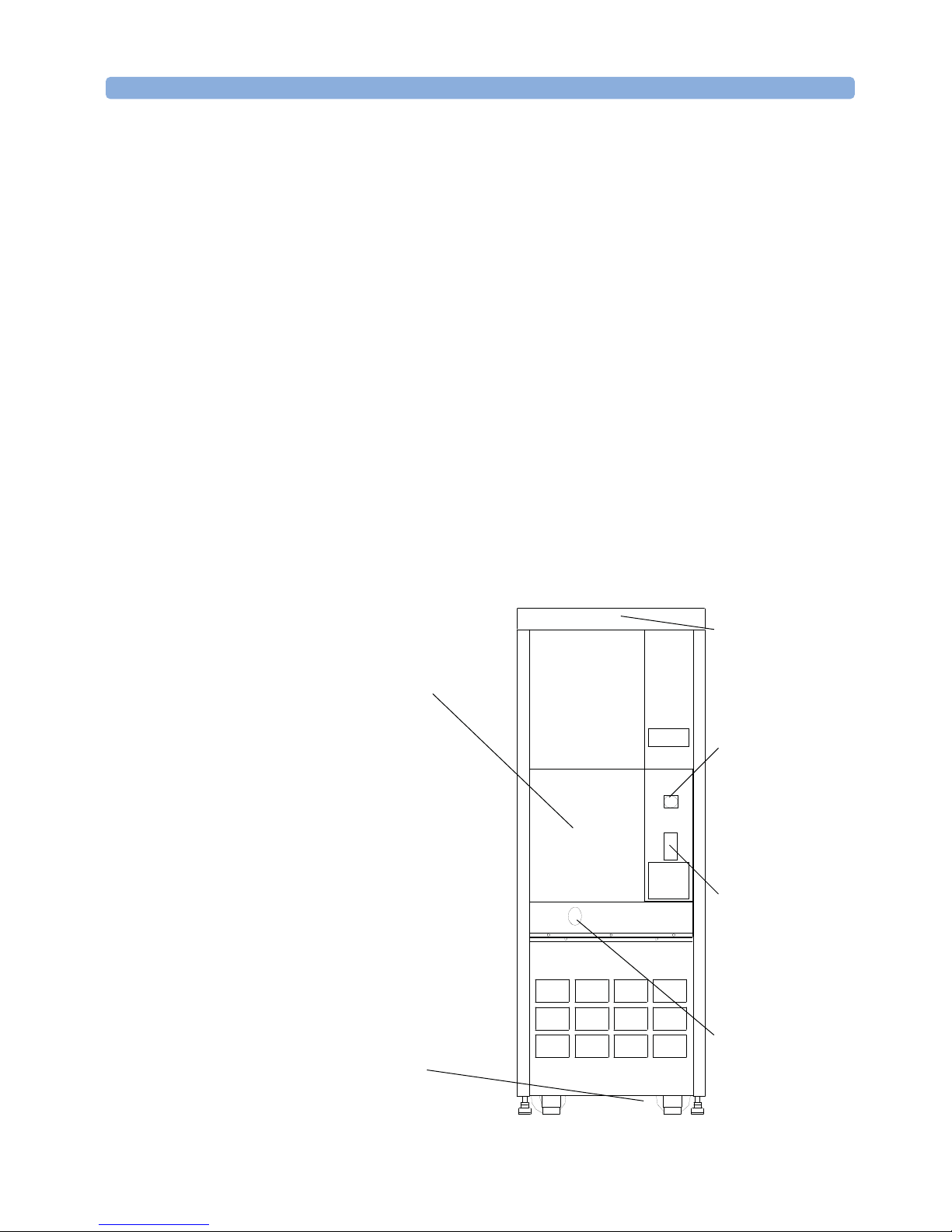
Figure 1 Input and output features and controls (front)
Output power block
(see
“Output
Connections” on
page 29
Supply input feed
(see
Connections” on
page 23
)
“Input
)
Fans (see
“Unpacking and
Placement” on
page 20
CPC connector –
External EMO and
auxiliary contacts
(see
“Output
Connections” on
page 29
Convenience
receptacles (see
“Output
Connections” on
page 29
Output conduit (see
“Output
Connections” on
page 29
)
)
)
ONEAC CDR45I Series Power Conditioner, Installation Guide, 913-521 Rev. A 13
Features and Controls I/O Features and Controls
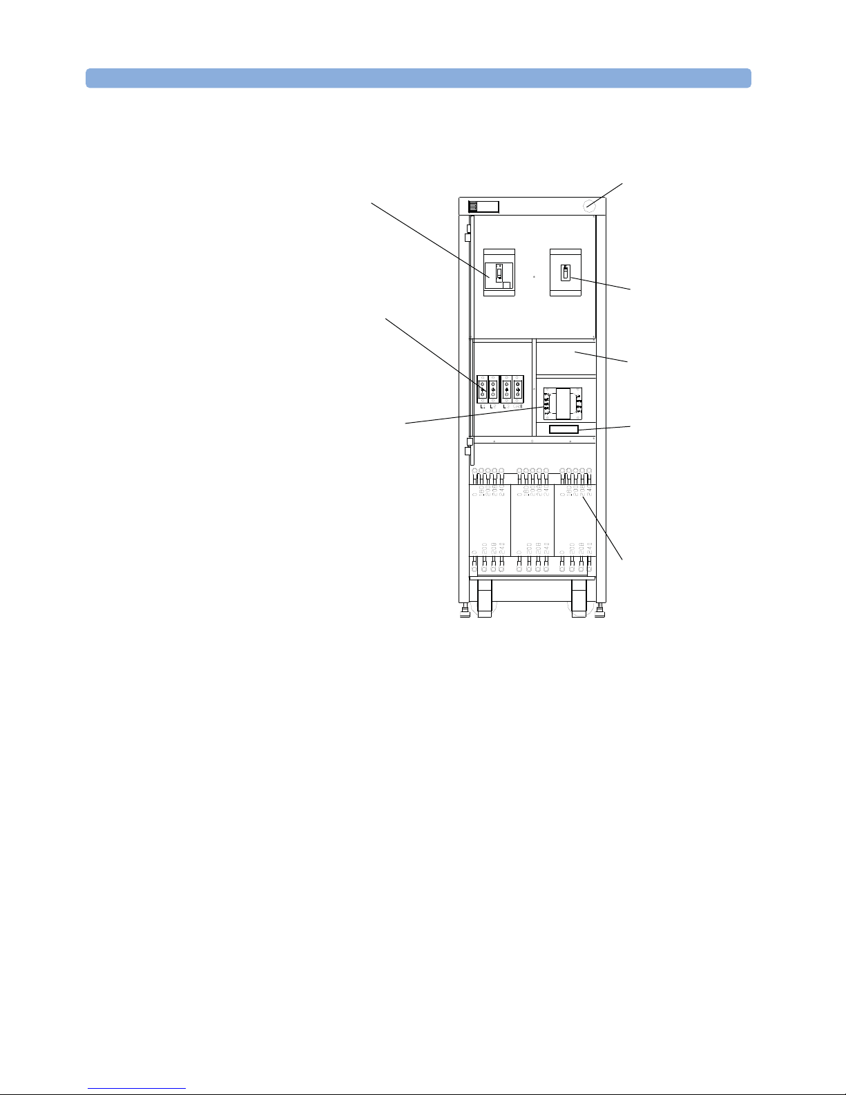
Figure 2 Input and output features and controls (rear)
Main input circuit
breaker
Input conduit
connection (see
“Input
Connections” on
page 23
EMO transformer (see
)
“Emergency
Mains Off” on
page 26
)
EMO red mushroom
turn-to-release
button (see
“Emergency
Mains Off” on
page 26
Main output circuit
breaker
Spares compartment
EMO transformer
fuses (see
“Emergency
Mains Off” on
page 26
and
“Cleaning” on
page 34
3 phase mains power
transformer (see
“Changing the
Operating
Voltage” on
page 51
)
14 ONEAC CDR45I Series Power Conditioner, Installation Guide, 913-521 Rev. A

Installation
Principle of Operation
The following brief description of the ONEAC CDR45I Series Power
Conditioner’s principle of operation is provided to assist in the proper
installation and operation of your power conditioner.
Interconnections and Operations:
1. AC power is supplied to the power conditioner by connection to the input
terminal block. When AC power is supplied to this terminal block via the
service panel circuit breaker, the Input Power ON LED is illuminated.
2. Three phase AC power is connected from the terminal block to the main
input circuit breaker. The input circuit breaker for this product utilizes
modular current trip rating plugs which are inserted or plugged into a single
molded case circuit breaker frame. An undervoltage release accessory is
installed in the input breaker as a means of control.
3. A separate multi-tapped primary, 24 Vac secondary, transformer is utilized
for power control, and supplied from the input terminal block (L1 and L2).
The primaries of this transformer are fuse protected (2A, 600 V rating). The
secondary of this transformer is also fuse protected (1A, 250 V rating).
4. The 24 Vac control circuit energizes the undervoltage release accessory
within the main input circuit breaker when the Emergency Mains Off
(EMO) circuit is closed. An external connection for the EMO circuit is
provided by means of a circular plastic connector (CPC) located on the
lower right back panel above the convenience receptacles. The power
conditioner is shipped with a shorting plug secured to the panel mounted
CPC. The shorting plug has a wire jumper across pins 3 and 4 of the CPC. A
spare mating CPC is provided with the unit in the spares compartment to
allow for this shorting plug to be replaced with any series connected NC
contact string. (See “Emergency Mains Off” on page 26 for detailed
description of operation.)
5. In order to turn ON the main input circuit breaker, the EMO circuit must be
closed so that the undervoltage release accessory is energized.
ONEAC CDR45I Series Power Conditioner, Installation Guide, 913-521 Rev. A 15

Installation Principle of Operation
6. Pins 1 and 2 of the CPC provide the user with a pair of contacts that are
opened when the EMO circuit has been alarmed and are closed during
normal unit operation. (See “Emergency Mains Off” on page 26 for detailed
description of operation.)
7. The secondaries of the Mains transformer are connected to the Virtual
Kelvin Ground®.
8. When the main input circuit breaker is turned ON, power is applied to the
cooling fans, and the main output circuit breaker. When the main output
circuit breaker in turned ON, the Output Power ON LED is illuminated and
power is available at the output power block.
NOTE Proper input voltage configuration is achieved by performing the following
three independent steps:
• Selection of the correct rating plug for the desired input voltage.
• Selection of the correct tap configuration for the Mains transformer (T1).
• Selection of the correct tap configuration for the Control transformer (T2).
The power conditioner is originally shipped from the manufacturer configured
for 400 Vac input operation unless otherwise stated on the label attached to the
input power block.
16 ONEAC CDR45I Series Power Conditioner, Installation Guide, 913-521 Rev. A

Installation Overview Installation
Installation Overview
NOTE Only qualified electricians shall install this power conditioner. Follow local
codes such as the U.S. National Electrical Code® [NFPA 70], good wiring
practice, and this Installation Guide.
To install the power conditioner:
1 Unpack the power conditioner (see “Unpacking and Placement” on
page 20).
2 Move the power conditioner to the desired installation location.
3 Turn off the intended input power source for the conditioner. In order to
comply with SEMI-S2-93A; 11.2, which complies with 29 CFR 1910.147
(OSHA), the power feed to the power conditioner must be locked out
and tagged out at the service disconnect that feeds the power
conditioner input power block to de-energize the power conditioner.
Connect the input wires (see “Input Connections” on page 23). A 5/16 inch
hex key is included in the spares compartment of the power conditioner for
use in connecting the input wires to the input power block. Use a grounding
conductor that is equal to or larger than the current carrying conductors. Do
not connect a neutral wire to the delta input of this power conditioner.
4 Verify that the power conditioner's input is configured for the correct supply
voltage (see “Changing the Operating Voltage” on page 51). The power
conditioner is originally shipped configured for 400 Vac input operation
unless otherwise stated on the label attached to the input power block.
5 Turn on the power feed to the input.
6 Turn on the input circuit breaker.
7 Turn on the output circuit breaker.
8 Verify the correct operation of the power conditioner as presented at the
output power block (see “Verifying the Installation” on page 19).
9 Turn OFF the input and output circuit breakers and the power feed to the
power conditioner. Refer to Item 3 above regarding lock out/tag out at the
service disconnect that feeds the power conditioner.
10 Confirm that tester input voltage is configured to match conditioner output
voltage.
11 Connect tester to the output power block (see “Output Connections” on
page 29).
12 Turn on the input circuit breaker.
ONEAC CDR45I Series Power Conditioner, Installation Guide, 913-521 Rev. A 17

Installation Important Installation Guidelines
13 Turn on the output circuit breaker.
14 Turn on your equipment.
15 Start normal operation of your system.
Important Installation Guidelines
Only qualified electricians should install or retrofit this power conditioner.
WARNING This power conditioner contains dangerous voltages. Accidental contact can
result in serious electrical shock. Always follow the U.S. National Electrical
Code® or your local electrical codes and good wiring practice.
CAUTION This Power Conditioner is 3-phase, wired in a “DELTA-WYE” configuration.
Figure 3 Power conditioner configuration
L1
L2
L3
PE
In order to comply with SEMI-S2-93A; 11.2, which complies with 29 CFR
1910.147 (OSHA), the power feed to the power conditioner must be locked
out and tagged out at the service disconnect that feeds the power
conditioner input power block to de-energize the power conditioner.
The input requires only 3-phase wires and a grounding conductor connection.
Do not connect a neutral wire to this delta configured input. The use of rigid
or flexible steel conduit is strongly preferred for this power conditioner model.
Physically separate the input power connections to the power conditioner from
the equipment power connections on the output. Data cables should be kept as
far away as possible from any power cables.
L1
L2
L3
N
PE
18 ONEAC CDR45I Series Power Conditioner, Installation Guide, 913-521 Rev. A

Verifying the Installation Installation
For maximum performance, use the flexible steel conduit provided with this
power conditioner to connect your equipment to the power conditioner. Always
include a ground wire for each auxiliary circuit on the output of the power
conditioner. Do not use extension cords or power strips. Do not connect your
equipment to the power conditioner’s output until the input connections have
been made and proper power conditioner configuration and operation has been
verified.
Verifying the Installation
Proceed as follows to verify the installation:
1 Turn OFF the input and main output circuit breakers on the power
conditioner. Verify that the installation follows the guidelines outlined in
“Important Installation Guidelines” on page 18. In order to comply with
SEMI-S2-93A; 11.2, which complies with 29 CFR 1910.147 (OSHA), the
power feed to the power conditioner must be locked out and tagged out
at the service disconnect that feeds the power conditioner input power
block to de-energize the power conditioner.
2 With your equipment still not connected to the power conditioner, turn ON
the main power source.
WARNING Dangerous voltages are present.
The Input Power ON LED indicator, located in the upper left hand corner of
the front of the power conditioner, will be illuminated and the 24 Vac control
circuit will then be activated.
3 Verify that the remote EMO shorting plug is connected to the power
conditioner (see “Emergency Mains Off” on page 26 and “Output
Connections” on page 29). Place the power conditioner’s input circuit
breaker in the ON position
4 Place the power conditioner’s output circuit breaker in the ON position. The
Output Power ON LED indicator, located in the upper left corner of the front
of the power conditioner will be illuminated.
Use a voltmeter to determine if voltage is present at the input and output.
Check the output voltage at the Output Power Block. The power
ONEAC CDR45I Series Power Conditioner, Installation Guide, 913-521 Rev. A 19

Installation Unpacking and Placement
conditioner's output voltage may run a few volts higher than the rated
voltage until the load is switched on.
If the operating voltage matches that suggested by the equipment
manufacturer, turn OFF the main input and output circuit breakers on the
power conditioner, connect your equipment to the output power block, and
turn ON the main input circuit breaker followed by the main output circuit
breaker. Your equipment can now be turned ON and operated as usual
If voltage variations greater than the manufacturer's specifications exist on
any phase, a tap selection for that phase may be made to adjust the voltage
level (see “Voltage Tap Selection and Range Change” on page 51).
If there is power at the input with no power at the output:
1 Turn OFF the main output and input circuit breakers.
2 Turn OFF the main power source supplying the power conditioner.
3 Follow the procedure in “Troubleshooting an Installation” on page 49.
Unpacking and Placement
Your ONEAC CDR45I Series Power Conditioner is delivered on a wooden
pallet. Upon arrival, inspect the unit and pallet for signs of damage. The pallet
has two types of shipping indicators (tip and drop). Check these indicators for
signs of shipping stress.
In case you encounter an activated tip or drop sensor or any visible damage
proceed as follows:
1 Make a note on the delivery receipt and inspect for damage.
2 Leave in original container and packaging and request immediate inspection
from carrier within 3 days.
3 Collect the following information and inform SSTD about the incident:
– Name of the carrier
– Shipment information
– Pictures showing the damage
– Detailed report explaining the damage
20 ONEAC CDR45I Series Power Conditioner, Installation Guide, 913-521 Rev. A
4 Keep all sensors and packaging material for further investigations.

Unpacking and Placement Installation
ONEAC recommends that your power conditioner be left on the pallet during
handling. Remove the conditioner from the pallet once it is as close as possible
to its final installation location. Unbolt the power conditioner and remove the
shipping brackets and roll it off the pallet using the shipping ramp.
WARNING Follow the ramp use instructions provided with the ramp. Do not use the
seismic anchoring holes on the side of the unit for lifting the power
conditioner into place.
Figure 4 Position of the seismic anchoring holes
3/8-16 UNC threaded
holes for seismic
mounting 12 places
The actual physical placement of the power conditioner should be as close as
possible to your equipment. The power conditioner should be installed inside
the room containing your equipment. Allow at least 2 inches (5.1 cm) around
all sides of the power conditioner. Do not allow the conditioner to be installed
where direct contact with water is possible or where the fans on the top of the
unit would be blocked.
ONEAC CDR45I Series Power Conditioner, Installation Guide, 913-521 Rev. A 21
Once the location of your power conditioner has been determined, carefully roll
it into place. Lower and adjust the glides on the power conditioner so that the
unit is level and stable. Run the glide locknut up to the base of the power
conditioner and tighten 1/4 turn to secure the glide at the height selected.

Installation Input Circuit Breaker
There are six, 3/8-16 size anchoring holes on each side of the conditioner. Three
bottom holes on each side are used in conjunction with two brackets to secure
the conditioner to the shipping pallet. Save the bolts and brackets when
unpacking the conditioner. Also included are six caps to cover the holes when
not in use.
Always anchor the conditioner with the bottom six holes for seismic restraint.
The shipping brackets may be used as part of the restraint if more suitable to a
specific installation. The 3/8-16 bolts may be used for supplementary restraint
in the top seismic holes. Never use the top seismic holes unless the conditioner
is already secured by the bottom six holes.
The power conditioners will not adversely impact system air conditioning. See
“Specifications” on page 41 for the air conditioning load per hour.
Input Circuit Breaker
This feature is needed to protect your equipment and the power conditioner.
Make sure the branch circuit breaker feeding the power conditioners input, at
the service disconnect, has ratings that are equal to or better than those listed
below for full rated power usage of the power conditioner.
Table 1 Input overcurrent protection
Product Input Voltage (Vac)
CDR45I 200, 208, 240 150 A 65,000
380, 400, 415, 440 90 A 25,000
448, 480 70 A 25,000
The input current rating can be changed with a plug-in module (rating plug)
which fits into the input circuit breaker.
Circuit Breaker
Current Rating
Interrupting Rating
(Minimum RMS
Symmetrical Amps)
22 ONEAC CDR45I Series Power Conditioner, Installation Guide, 913-521 Rev. A

Input Connections Installation
Input Connections
This feature is used for connecting the input AC power connections to the
power conditioner. The internal input power block is located in the front-
middle, on the left side, below the main input circuit breaker. The power block
will accept wire size 6 AWG-350 MCM (16-177 mm2). There is a conduit hole
on the bottom of the power conditioner to connect a 51 mm (2 inch) conduit.
Supply access to the power conditioner can be easily accomplished from the
front or back sides through this bottom conduit hole. If desired, access through
the top of the power conditioner is provided through the internal sheet metal. A
63.5 mm (2.5 inch) hole, or smaller, can be punched or drilled through the top
of the power conditioner, above the main input circuit breaker to allow access to
the input power block below.
A 5/16" hex key is supplied with the power conditioner for use in connecting
the input and output wires to their respective power blocks. The hex key is
stored in the spares compartment, behind the middle panel on the front of the
unit.
Installation of Input Connections
WARNING Turn off the main power source supplying the power conditioner at the service
disconnect before proceeding.
In order to comply with SEMI-S2-93A; 11.2, which complies with 29 CFR
1910.147 (OSHA), the power feed to the power conditioner must be locked
out and tagged out at the service disconnect that feeds the power
conditioner input power block to de-energize the power conditioner.
To install the input connections:
1 Open the door and remove the lower and middle cover panels to access the
internal input connections for bottom feed input. For top feed input, remove
the upper and middle cover panels.
2 Install an appropriate conduit and fitting or cord with cord connector to the
power conditioner.
A conduit hole for 51 mm (2 inch) conduit is provided (see Figure 5).
ONEAC CDR45I Series Power Conditioner, Installation Guide, 913-521 Rev. A 23

Installation Input Connections
Figure 5 Conduit hole
Hole for 2 inch (51 mm)
conduit
3 Connect the input ground or protective earth (PE) conductor to the terminal
block (PE).
Heavy gauge wire, equal to or larger in diameter than the power carrying
conductors should be used to connect the safety ground or protective earth
conductor (PE). It is recommended that ground or PE be wired back to the
service ground/main earth terminal.
Do not rely on the conduit alone for connection to ground or earth.
Do not use a ground conductor size that is smaller than the phase conductor.
Refer to the wiring charts on the following page.
If in doubt regarding wire sizing, consult the U.S. National Electrical Code
Table 310-16, or your local electrical code.
®
,
24 ONEAC CDR45I Series Power Conditioner, Installation Guide, 913-521 Rev. A

Input Connections Installation
4 Connect the input phase wires to the input terminals. Phase rotation
sequence is maintained by the power conditioner. Refer to the following
wiring charts:
Table 2 Minimum wire sizes (in conduit) for different input voltages and Full Rated Load
of Power Conditioner
Product CDR45I
Input Voltage
200 #0 AWG #0 AWG
208 #0 AWG #0 AWG
240 2 AWG 2 AWG
380 4 AWG 4 AWG
400 4 AWG 4 AWG
415 4 AWG 4 AWG
440 4 AWG 6 AWG
448 4 AWG 6 AWG
480 6 AWG 6 AWG
* Wire insulation rated for 75 ˚C minimum is required.
Table 3 Wire size metric conversion chart
Wire Size
(AWG)
Diameter
(MILS)
0000 AWG 460 MILS 11.7 mm 107 mm
000 AWG 410 MILS 10.4 mm 85.0 mm
00 AWG 365 MILS 9.27 mm 67.4 mm
0 AWG 325 MILS 8.25 mm 53.5 mm
2 AWG 258 MILS 6.54 mm 33.6 mm
3 AWG 229 MILS 5.88 mm 26.7 mm
4 AWG 204 MILS 5.19 mm 21.2 mm
6 AWG 162 MILS 4.12 mm 13.3 mm
8 AWG 128 MILS 3.26 mm 8.37 mm
10 AWG 102 MILS 2.59 mm 5.26 mm
Input Wire Size* Input Grd. Wire Size*
Diameter
(mm) Area (mm2)
2
2
2
2
2
2
2
2
2
2
Standard
Metric (mm2)
110 mm
85 mm
70 mm
60 mm
35 mm
30 mm
25 mm
16 mm
10 mm
6 mm
2
2
2
2
2
2
2
2
2
2
ONEAC CDR45I Series Power Conditioner, Installation Guide, 913-521 Rev. A 25
5 Follow the procedure in “Verifying the Installation” on page 19.

Installation Emergency Mains Off
Emergency Mains Off
This feature will allow you to shut down your power conditioner by pushing the
red, mushroom-type EMERGENCY MAINS OFF (EMO) turn-to-release
button located on the front upper right corner.
After the EMO circuit has been deployed, the input circuit breaker will need to
be reset (switched to the OFF position, then the ON position) to resume normal
operation.
CAUTION Hazardous voltages will still be present within the power conditioner even after
the EMO has been deployed.
You must turn off the power source supplying the power conditioner at the
service disconnect to remove all hazardous voltages before servicing or
working within the power conditioner. In order to comply with SEMI-S2-
93A; 11.2, which complies with 29 CFR 1910.147 (OSHA), the power feed
to the power conditioner must be locked out and tagged out at the service
disconnect that feeds the power conditioner input power block to de-
energize the power conditioner.
The EMO circuitry is integrated with the input circuit breaker with a 24 Vac
undervoltage release circuit and controlled by a 24 Vac transformer, which is
located in the control transformer area. The transformer is powered prior to the
input circuit breaker and is protected by two fuses (2 A, 600 V) on the primary
side located below the transformer and behind the middle front panel. The
secondary side of the transformer is fuse protected (1 A, 250 V) to limit the
current to 1 A maximum. This fuse is also located in the same compartment. A
schematic of the 24 Vac control circuit is found at the end of this section.
The conditioner 24Vac EMO circuit is forms a closed loop for normal
operation. The loop includes: the red EMO button (contacts open when button
depressed), a microswitch S2 behind lower front access panel (contacts closed
when switch is depressed by panel), and remote EMO contacts J1-3 and J1-J4
(a closed loop is required between these pins). When the EMO loop is closed,
24Vac is provided to the undervoltage coil of the input circuit breaker
permitting it to be set to ON Opening the loop by depressing the red button or
other interruption will cause the input circuit breaker to OPEN and remove
power from the conditioner load. Releasing the red EMO button (turn to
release) will restore 24 Vac to the undervoltage coil and permit the input circuit
breaker to be re-set to OFF then to ON.
26 ONEAC CDR45I Series Power Conditioner, Installation Guide, 913-521 Rev. A

Emergency Mains Off Installation
A circular plastic connector (CPC) is provided on the back of the power
conditioner, located above the convenience receptacles, to allow for an external
connection to the EMO circuit. A series connected, normally closed string of
contacts or switches must be connected between J1-3 and J1-4 of the CPC. The
conditioner will not function unless a closed loop exists between these two
pins. The power conditioner is shipped with a shorting plug (P1) connected to
the panel to allow for field installation and verification. An additional plug with
4 loose pins is shipped with the conditioner. They are stored in the spares
compartment above the control transformer.
Pins P1-1 and P1-2 are not used in the shorting plug provided. A pair of
contacts, K1A is connected to J1-1 and J1-2 for future user specific circuits.
The contact pair is rated at 250 Vac, 1 A. The relay coil, K1, is energized when
power is available to the input circuit breaker undervoltage coil for normal
operation. The contact pair K1A is closed when relay K1 is energized.
Alarming the EMO circuit removes power from K1 at the same time as the
input circuit breaker undervoltage coil is de-energized. The contact pair K1A
will open. Restoring 24 Vac power to normal will close the contact pair K1A.
Note that K1A will be closed whenever the EMO 24V ac power loop is normal
even if the input circuit breaker has not been turned ON.
The following is a list of ONEAC and manufacturer part numbers for the CPC
plug, cable clamp and pins used for this circuit.:
Table 4 ONEAC and manufacturer part numbers
Part Description Oneac Part # Manufacturer Mfr Part #
CPC Plug (P1) 435-260 AMP 206429-1
CPC Cable Clamp 435-262 AMP 206062-3
Pin (#18-#14 AWG) 421-270 AMP 66361-4
ONEAC CDR45I Series Power Conditioner, Installation Guide, 913-521 Rev. A 27

Installation Emergency Mains Off
When the power source voltage supplying the power conditioner is
changed, the EMO transformer, T2, must be reconfigured on the primary
to match the source voltage (refer to Figure 6 for information).
Figure 6 24 Vac control circuit
WARNING You must turn off the power source supplying the power conditioner at the
28 ONEAC CDR45I Series Power Conditioner, Installation Guide, 913-521 Rev. A
In order to comply with SEMI-S2-93A; 11.2, which complies with 29 CFR
1910.147 (OSHA), the power feed to the power conditioner must be locked
out and tagged out at the service disconnect that feeds the power
conditioner input power block to de-energize the power conditioner.
service disconnect to remove all hazardous voltages before servicing or
working within the power conditioner.

Output Connections Installation
WARNING You must turn off the power source supplying the power conditioner at the
service disconnect to remove all hazardous voltages before servicing or
working within the power conditioner.
Figure 7 Position of emergency off fuses and emergency off transformer
Emergency off
transformer
Emergency off fuses
Output Connections
Output Overview
The output power block allows easy connection of output wiring to your
equipment connections. The output conduit landing area is located just below
the output power block. Please confirm that conditioner output voltage and
tester input voltage match before connecting power.
All power, control, and sense circuits are connected between the power
conditioner and your equipment via the output conduit connections and the
CPC connector located on the back of the power conditioner.
ONEAC CDR45I Series Power Conditioner, Installation Guide, 913-521 Rev. A 29

Installation Output Connections
Figure 8 Position of the output connections
Convenience
Receptacle Circuit
Breakers
CPC connector –
external EMO and
auxiliary contacts
Output power block
Three IEC-320
receptacles, 208 Vac,
Conduit landing
total 10 A max
Two duplex NEMA
5-15R receptacles,
120 Vac, 15 A max,
each (Behind cover)
Conduits
The landing area can be fitted with up to five conduits landing points, and up to
51 mm (2 inch) diameter conduits. Knockout scribe points are located on the
back side of the conduit landing cover plate for your convenience.
Convenience Receptacles
Convenience receptacles are located on the back of the conditioner. Three (3)
IEC320 outlets are provided and rated at 208Vac,10 A maximum for all three.
Two (2) separate NEMA 5-15R duplex receptacles are provided and rated at
120 Vac, 15 A maximum for each duplex. These NEMA style receptacles are
shipped covered by a panel for compliance with the EU's low voltage directive.
Each convenience circuit is circuit breaker protected. The convenience
receptacles can be energized by their individual circuit breakers once the main
input circuit breaker is turned ON.
30 ONEAC CDR45I Series Power Conditioner, Installation Guide, 913-521 Rev. A

Output Connections Installation
Installation of Output Connections
WARNING Turn off the main power source supplying the power conditioner at the service
disconnect before proceeding.
Turn OFF the service disconnect supplying power to the power conditioner
and connect your equipment to the power conditioner’s output. The power
conditioner maintains phase rotation sequence. Follow lock out
procedures.
1 Turn OFF the equipment power switch or circuit breaker before turning ON
the main output circuit breaker on the power conditioner.
2 Turn ON the appropriate circuit breaker(s) on the power conditioner's input
and output and then turn ON the protected equipment power switch or circuit
breaker.
Each power run should be unique to each piece of equipment in the system.
The use of temporary power taps should be avoided. Even the use of duplex
receptacles should be avoided in the case of electrically noisy loads. (i.e.
laser printers, phase regulated power supplies, etc.).
It is recommended that the power runs on the output of the conditioner be as
short as possible, with a maximum length of 15 m (50 feet).
3 Torque all connections.
Refer to the torque specifications in “Maintenance” on page 33.
4 Follow the procedure in “Verifying the Installation” on page 19.
ONEAC CDR45I Series Power Conditioner, Installation Guide, 913-521 Rev. A 31

Installation Output Connections
32 ONEAC CDR45I Series Power Conditioner, Installation Guide, 913-521 Rev. A

Maintenance
Maintaining the correct operation of your power conditioner is limited to
annually checking the operating voltage and torquing all the connections.
WARNING Turn off the input and main output circuit breakers on the power conditioner.
Turn off the power source supplying the power conditioner at the service
disconnect before proceeding.
In order to comply with SEMI-S2-93A; 11.2, which complies with 29 CFR
1910.147 (OSHA), the power feed to the power conditioner must be locked
out and tagged out at the service disconnect that feeds the power
conditioner input power block to de-energize the power conditioner.
Torque specifications Circuit Breakers torque specification—on circuit breaker label.
Power Blocks torque specification—on power block label.
Table 5 Torque specifications
Location
example
Transformer
Mounting
Wires 5/16 Steel 12 140 16.3
Misc. Conn. #10 Steel 32 3.6
Capacitors #8 Steel 20 2.3
PCB #6 Steel 11 1.2
TWL Recept #6 16 1.8
Dup Recept #6 12 1.4
Note: normalized torque conversions S.A.E. to metric.
Bolt size Material
1/2 Stainless
Steel
1/4 Steel 6 75 8.1
3/8 Brass 20 240 27
5/16 Brass 11 132 14.9
1/4 Brass 6 75 8.1
#10 Brass 20 2.3
#8 Brass 16 1.8
#6 Brass 8 0.9
Torque
(ft./lb) (in./lb) (Nm)
45 540 61
ONEAC CDR45I Series Power Conditioner, Installation Guide, 913-521 Rev. A 33

Maintenance Cleaning
Cleaning
The power conditioner is painted with a textured paint to minimize noticeable
dirt and fingerprints. The outside may be wiped clean with a slightly damp
cloth.
Fuse Replacement
The ONEAC CDR45I Series Power Conditioners require fuses in some
locations. In the unlikely event that a fuse needs to be replaced, spare fuses have
been provided in the internal spares compartment behind the middle front panel
which covers the EMO transformer and the power terminal block.
All fuses are service personnel replaceable only. Since all fuses are located
behind secured panels and/or covers limiting access to hazardous voltages, only
qualified electricians should replace them. The fuse locations and specifications
are as follows:
Table 6 Fuse locations and specifications
Location Input
Emergency OFF
Primary (2) 600 Vac 2 Amp Littelfuse KLDR2
Secondary (1) 250 Vac 1 Amp Littelfuse FLM-1
Follow lock out recommendations described in “Installation Overview” on
page 17 (step 3).
Fuse current
rating Sources Part numbers
Bussmann LP-CC-2
Gould ATDR2
Bussman FNM-1
34 ONEAC CDR45I Series Power Conditioner, Installation Guide, 913-521 Rev. A

Fuse Replacement Maintenance
To replace a fuse:
WARNING Turn off the power source supplying the power conditioner at the service
disconnect before proceeding.
1 Turn OFF the power conditioner’s output circuit breaker.
2 Turn OFF the power conditioner’s input circuit breaker.
3 Turn OFF the power conditioner’s input power feed.
4 To replace the fuse(s), open the door. Remove middle panel over the EMO
transformer.
5 Remove and replace the fuse(s) as needed.
6 Replace the middle panel and close the door.
Figure 9 Fuse replacement
ONEAC CDR45I Series Power Conditioner, Installation Guide, 913-521 Rev. A 35
Emergency OFF
Safety interlock
switch
Emergency OFF
(EMO) fuses
(EMO)
transformers
7 Follow the procedure in “Verifying the Installation” on page 19.

Maintenance Fuse Replacement
36 ONEAC CDR45I Series Power Conditioner, Installation Guide, 913-521 Rev. A

Operation of Additional Features
Indicators This feature provides a visual indication of the operational status of your power
conditioner as integrated to your equipment.
All LEDs used as indicators are Class I devices (as per IEC 845/84 and 21 CFR
1040.10).
Figure 10 Visual indication of the operational status
Input power applied to power conditioner
Main output circuit breaker
ON Power available at output
power block
ONEAC CDR45I Series Power Conditioner, Installation Guide, 913-521 Rev. A 37

Operation of Additional Features
38 ONEAC CDR45I Series Power Conditioner, Installation Guide, 913-521 Rev. A

Physical Views
Figure 11 Physical views
Front Back Side
Top
ONEAC CDR45I Series Power Conditioner, Installation Guide, 913-521 Rev. A 39
Bottom

Physical Views
40 ONEAC CDR45I Series Power Conditioner, Installation Guide, 913-521 Rev. A

Specifications
CDR45I Specifications
Output ratings 45 kVA 3-phase 208/120 Vac Wye, 125 amps/phase max.
Convenience circuits Single phase 120 Vac; 2 @ 15 A max
Single phase 208 Vac; 1 @ 10 A max
Input ratings 3-phase DELTA (Nominal voltages measured phase to phase)
Voltage/V Current/A
200 130
208 130
240 110
380 75
400 70
408 70
415 65
440 65
448 60
480 55
Frequency 50/60 Hz
Voltage tolerance ± 10%
Input overcurrent protection Single frame circuit breaker with trip current rating plug for 90 A. Spare rating
ONEAC CDR45I Series Power Conditioner, Installation Guide, 913-521 Rev. A 41
plugs for 70 A and for 150 A included inside unit.

Specifications CDR45I Specifications
Input voltage tap Factory configured for 400 Vac, unless otherwise labelled on the input power
block. Any mains transformer jumpers required that are not already in use on
the transformer primaries will be shipped inside the unit within the spares
compartment.
Input connections Prepared for fixed wiring of power line cable to internal power block. Accepts
wire size 6AWG - 350 MCM (16-177 mm2)
Adaptable for steel or flexible steel conduit fed from bottom or top of unit (2
inch (51 mm) hole in base or shim or punch to size).
Output connections Prepared for fixed wiring of power line cable to internal power block. Accepts
wire size 6AWG - 350 MCM (16-177 mm2).
Conduit steel or flexible steel fed from rear of unit (up to five (5) 2 inch (51
mm) holes in conduit landing panel punched as required.)
Convenience outlets Three (3) IEC 320 outlets rated 120 Vac, 10 A max.
Outlets labeled “1:10A 208 V Max. Output”.
Two (2) NEMA 5-15R duplex outlets rated 120 Vac, 15 A max, each. Covered
with a steel plate for CE compliance.
Outlets labeled: “2: 15 A 120 V Max. Output” and “3: 15 A 120 V Max.
Output”.
Corresponding circuit breakers labeled: “Convenience outlets: 1,2,3”.
Convenience outlets are energized when main input circuit breaker is turned
ON and individual convenience circuit breaker is turned ON.
Main output circuit breaker Energizes main output power block only.
Failsafe EMO Red mushroom push button remains depressed in activated position until
manually released. Button labeled “EMERGENCY OFF”.
Employs a 24 Vac control circuit powered from an isolation transformer with
dual primaries for various input voltage configurations from 200 to 480 Vac.
The 24 Vac control transformer is energized prior to the main input circuit
breaker. The control circuit is fuse protected on both the primary and secondary
sides.Two (2) spare primary fuses (2A, 600 Vac) and one (1) spare secondary
fuse (1A, 250 Vac) are provided and shipped with the unit in the spares
compartment.
Limited to 1.0 amp. An external normally closed (NC) contact or series string
of NC contacts, can be connected in the series contact circuit by removing the
shorting plug shipped with the unit and connecting across pins J1-3 and J1-4 of
the CPC connector. This CPC connector is located on the back of the
conditioner. A spare mating plug (P1) is supplied with 4 loose pins and one
cable strain relief with each unit in the spares compartment.
42 ONEAC CDR45I Series Power Conditioner, Installation Guide, 913-521 Rev. A

CDR45I Specifications Specifications
Normally open contacts. A single pair of normally open contacts are provided
whose coil is de-energized if the EMO contact circuit is opened. The normally
open contacts are accessed at pins J1-1 and J1-2 of the CPC connector.
Indicator lights Green LED for incoming Input Power ON or power applied to the conditioner.
Green LED for Output Power ON or power applied to the main output power
block.
Forward transfer impedance < 0.5 Ohms @ 1 KHz, L-N
< 0.05 Ohms @ 50/60 Hz L-N
Efficiency at rated load > 97% @ 50 Hz.
Heat loss @ 80% of rated load 1170 watts (4000 BTU/hr.).
Load regulation response time < 2 msec for a 50% change in load.
Surge Voltage withstand ANSI/IEEE C62.41: Category A, 6 kV, 200 A 100 kHz ringwave, And
Category B, 6 kV, 500 A 100 kHz ringwave and 3000 A impulse.
Surge voltage let-thru With unit under power, ANSI/IEEE C62.41 Category A 6 KV, 200 A. 100 kHz
ringwave surge applied yields < 10 V normal mode (L-N) and < 0.5 V common
mode (N-PE) at the output power block.
Overload capability Can typically tolerate 10 times rated output for 0.5 cycle, 5.5 times rated output
for 1 second, and 3.5 times rated output for 5 seconds without degradation.
Magnetic stray field operating < 5 Gauss (0.5 mTesla) anywhere on the conditioner’s surface for frequencies
less than or equal to 198 Hz under full rated load current into resistive load.
(Actual measurements indicate that < 1 Gauss peak except immediately above
the fans where < 3 Gauss peak.
Magnetic stray field non operating < 2 mGauss (0.2 µTesla) anywhere around conditioner. Measured at a distance
of 2.1m from conditioner. (IATA-Limit)
Operating temperature 0 ˚C to +40 ˚C
Storage temp –40 ˚C to +70 ˚C
Elevation 3,000 meters (10,000 ft.) max.
Relative humidity 80% @ 30 ˚C
Qualified for 48 hours in 91% to 95% RH @ 25 ˚C (as per EN60950)
Qualification test, non operating 12 hours at 65 ˚C and 90% RH
Cooling Forced air cooled
ONEAC CDR45I Series Power Conditioner, Installation Guide, 913-521 Rev. A 43

Specifications CDR45I Specifications
Approvals & markings UL, cUL, under bi-national standard UL1012.
CE Marked in compliance with EU directives and relative to EN60950.
SEMI S2-93A-compliant
Dimensions
(W x H x D): 55.1 cm x 157.5 cm x 52.1 cm (21.67" x 62.00" x 20.50")
Total footprint 2870 cm (445 inch)
Unit weight Approx. 400 kilograms (885 lbs.). Shipping weight approx. 470 kilograms
(1035 lbs).
Packaging Reusable pallet and crate with included ramp having dimensions of (LxWxH)
95.3 cm x 83.8 cm x 181.0 cm (37.5" x 33" 71.75")
Packaging specifications Crated unit meets ISTA test procedure 1B (6/99).
44 ONEAC CDR45I Series Power Conditioner, Installation Guide, 913-521 Rev. A

CDR45I Schematics Specifications
CDR45I Schematics
Figure 12A CDR45I Schematic (1)
ONEAC CDR45I Series Power Conditioner, Installation Guide, 913-521 Rev. A 45

Specifications CDR45I Schematics
Figure 13A CDR45I Schematic (2)
Figure 14A CDR45I Schematic (3)
46 ONEAC CDR45I Series Power Conditioner, Installation Guide, 913-521 Rev. A

CDR45I Schematics Specifications
Figure 15A CDR45I Schematic (4)
Figure 16A CRD45I Schematic (5)
ONEAC CDR45I Series Power Conditioner, Installation Guide, 913-521 Rev. A 47

Specifications CDR45I Schematics
48 ONEAC CDR45I Series Power Conditioner, Installation Guide, 913-521 Rev. A

Troubleshooting an Installation
NOTE The conditioner is designed for repair ONLY by personnel trained to
repair this model. Repair by other personnel is not recommended.
1 If there is power at the input with no power at the output, turn OFF the
output circuit breaker and then the input power to the conditioner—the main
power source or service disconnect.
2 Check the values specified on the nameplate.
3 Verify that your main power source is correct for the power conditioner’s
input voltage.
4 Verify that the power conditioner’s input voltage has not been changed in the
field.
If everything seems correct, disconnect the line and ground input wires and then
contact ONEAC Technical Services.
Technical Support
ONEAC offers 24-hour technical support. If you have questions or problems
regarding your ON Series UPS.
If you are unable to troubleshoot the problem, contact ONEAC Technical
Services. Refer to “Technical Support” on page 11, for the correct telephone
number in your area. Technical Services will ask you to describe the problem.
We will help solve the problem over the telephone or issue a Return Material
Authorization (RMA) number along with instructions on how to return the
power conditioner.
You will need to supply the service representative with the power conditioner
part number and serial number. These are found on the serial number/rating
label on the left side of the power conditioner.
Always check with ONEAC Technical Services before attempting to repair or
return any ONEAC product.
ONEAC CDR45I Series Power Conditioner, Installation Guide, 913-521 Rev. A 49

Troubleshooting an Installation Technical Support
50 ONEAC CDR45I Series Power Conditioner, Installation Guide, 913-521 Rev. A

Changing the Operating Voltage
V oltage Tap Selection and Range
Change
Tap selection allows a permanent adjustment to the voltage level of any phase.
If the nominal output level is not within the equipment manufacturer’s
suggested operating range, you can move the power tap on the primary of the
power conditioners transformer.
Multiple input primary taps allow for a wide variety of input voltage
configurations presented around the world. Tap selection can also correct for
steady-state variances in nominal line voltage.
Tap selection is not available on the output.
Voltage tap selection:
1 Turn OFF the power conditioner’s output circuit breaker.
2 Turn OFF the power conditioner’s input circuit breaker.
3 Turn OFF the power conditioner’s input power at the service disconnect.
WARNING Turn off the power source supplying the power conditioner at the service
disconnect before proceeding. The MAINS OFF transformer will still be
powered unless the service disconnect is open!
In order to comply with SEMI-S2-93A; 11.2, which complies with 29
CFR 1910.147 (OSHA), the power feed to the power conditioner must be
locked out and tagged out at the service disconnect that feeds the power
conditioner input power block to de-energize the power conditioner.
4 Take off the bottom cover panel to expose the main transformer
compartment. The safety interlock will shut down power when the cover
panel is removed.
5 Remove the mid-front panel to expose the EMO transformer and its taps.
ONEAC CDR45I Series Power Conditioner, Installation Guide, 913-521 Rev. A 51

Changing the Operating Voltage Voltage Tap Selection and Range Change
6 Refer to the transformer tap selection chart attached to the inside of the
power conditioner’s door or the figure at the end of this section.
7 Verify that the correct input circuit breaker rating plug has been installed
(see “Input Circuit Breaker” on page 22).
8 Do not change the location of any wires which are connected to the
transformer's primary circuit breaker or on the transformer's secondary.
9 Torque all connections as per section “Maintenance” on page 33.
10 Re-install both cover panels.
11 Mark any nominal voltage changes on or near the rating nameplate.
12 Follow the procedure in “Verifying the Installation” on page 19.
52 ONEAC CDR45I Series Power Conditioner, Installation Guide, 913-521 Rev. A

Voltage Tap Selection and Range Change Changing the Operating Voltage
TapJ
Table 7 Mains (T1) transformer voltage tap selection
Input A
Voltage
200 A1 B1 C1 A1-A6 A3-A7 A3-B1 B1-B6 B3-B7 B3-C1 C1-C6 C3-C7 C3-A1
208 A1 B1 C1 A1-A6 A4-A8 A4-B1 B1-B6 B4-B8 B4-C1 C1-C6 C4-C8 C4-A1
240 A1 B1 C1 A1-A6 A5-A9 A5-B1 B1-B6 B5-B9 B5-C1 C1-C6 C5-C9 C5-A1
380 A1 B1 C1 A2-A6 A7-B1 B2-B6 B7-C1 C2-C6 C7-A1
400 A1 B1 C1 A3-A6 A7-B1 B3-B6 B7-C1 C3-C6 C7-A1
408 A1 B1 C1 A3-A6 A8-B1 B3-B6 B8-C1 C3-C6 C8-A1
415 A1 B1 C1 A4-A6 A8-B1 B4-B6 B8-C1 C4-C6 C8-A1
440 A1 B1 C1 A5-A6 A7-B1 B5-B6 B7-C1 C5-C6 C7-A1
448 A1 B1 C1 A5-A6 A8-B1 B5-B6 B8-C1 C5-C6 C8-A1
480 A1 B1 C1 A5-A6 A9-B1 B5-B6 B9-C1 C5-C6 C9-A1
(black)
Input B
(red)
Input C
(blue)
Jumper Jumper
Delta
Jumper
Jumper Jumper
Delta
Jumper
Jumper Jumper
Delta
Jumper
Figure 17 Mains (T1) transformer voltage tap selection
Input Breaker Module:
Must match current rating for selected
input voltage (see User Manual).
umpers:
Stored in spares
compartment
behind panel
200, 208, 240 V 150 A
380, 400, 415, 440 V 90 A
448, 480 V 70 A
T2:
24 Vac Control
Transformer
T1:
Mains Transformer
T1 – Mains transformer taps
To Configure Input Voltage:
1. Change/verify types are correct for both T1 and T2
2. Change/verify Input Breaker Module correct for input voltage
ONEAC CDR45I Series Power Conditioner, Installation Guide, 913-521 Rev. A 53

Changing the Operating Voltage Voltage Tap Selection and Range Change
Table 8 24 Vac control (T2) transformer voltage tap selection
Voltage Black lead Red lead Jumper Jumper
200 D7 D6 D1 – D6 D3 – D7
208 D8 D6 D1 – D6 D4 – D8
240 D9 D6 D1 – D6 D5 – D9
380 D2 D6 D1 – D7
400 D3 D6 D1 – D7
408 D3 D6 D1 – D8
415 D4 D6 D1 – D8
440 D5 D6 D1 – D7
448 D5 D6 D1 – D8
480 D5 D6 D1 – D9
Figure 18 T2 – 24 Vac control Xfmr taps
54 ONEAC CDR45I Series Power Conditioner, Installation Guide, 913-521 Rev. A

Warranty
Warranty
ONEAC warrants its products to be free from defects in materials and
workmanship for a period of five years. This warranty is limited to repairing or
replacing, at ONEAC’s option, any defective component, circuit board or
module contained within the product only when it is returned with an ONEAC
Return Material Authorization (RMA) number to ONEAC or to an ONEAC-
designated repair facility. In all cases, shipping charges to and from ONEAC or
the ONEAC-designated repair facility are at the customer’s expense.
Certain modules or peripherals included with the product but not manufactured
by ONEAC are warranted for ninety days or to the extent of the manufacturer’s
warranty, whichever is longer.
Limitations of Warranty – This limited warranty does not cover any losses or
damage resulting from shipment to or from the customer, or from improper
installation, environment or abuse, or from any modifications, adjustments or
repair by other than ONEAC-authorized personnel.
Exclusive Remedies – Except as set forth herein and except as to title, there are
no warranties, express or implied, or any affirmations of fact or promises by
ONEAC with reference to the products or their merchantability or fitness for
any particular purpose. In no event shall ONEAC be liable for lost profits,
goodwill or any other special or consequential damages.
If it becomes necessary to return a power conditioner, contact ONEAC for a
Return Material Authorization (RMA) number. This number must be marked
on the shipping carton and packing slip of the unit being returned. Shipping
charges are to be borne buy the customer. Customers will be billed repair
charges for shipping damages resulting from inadequate packaging of the
product being returned.
ONEAC CDR45I Series Power Conditioner, Installation Guide, 913-521 Rev. A 55
 Loading...