

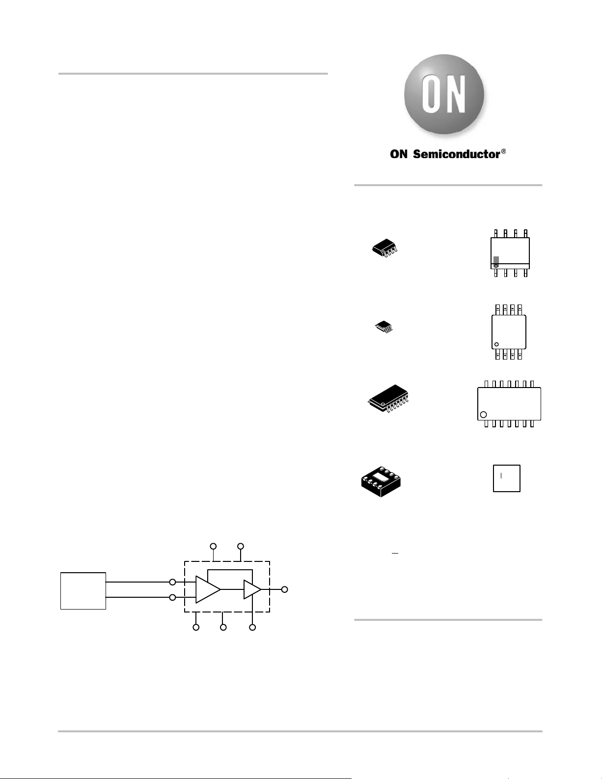
MC100EL1648
5 V ECL Voltage Controlled
Oscillator Amplifier
Description
The MC100EL1648 is a voltage controlled oscillator amplifier that
requires an external parallel tank circuit consisting of the inductor (L)
and capacitor (C). A varactor diode may be incorporated into the tank
circuit to provide a voltage variable input for the oscillator (VCO).
This device may also be used in many other applications requiring a
fixed frequency clock.
The MC100EL1648 is ideal in applications requiring a local
oscillator, systems that include electronic test equipment, and digital
high−speed telecommunications.
The MC100EL1648 is based on the VCO circuit topology of the
MC1648. The MC100EL1648 uses advanced bipolar process
technology which results in a design which can operate at an extended
frequency range.
The ECL output circuitry of the MC100EL1648 is not a traditional
open emitter output structure and instead has an on−chip termination
emitter resistor, R
direct ac−coupling of the output signal into a transmission line.
Because of this output configuration, an external pull−down resistor is
not required to provide the output with a dc current path. This output is
intended to drive one ECL load (3.0 pF). If the user needs to fanout the
signal, an ECL buffer such as the EL16 (EL11, EL14) type Line
Receiver/Driver should be used.
Features
• Typical Operating Frequency Up to 1100 MHz
• Low−Power 19 mA at 5.0 Vdc Power Supply
• PECL Mode Operating Range: V
• NECL Mode Operating Range: V
to −5.5 V
• Input Capacitance = 6.0 pF (TYP)
• Pb−Free Packages are Available
NOTE: The MC100EL1648 is NOT useable as a crystal oscillator.
EXTERNAL
TANK
CIRCUIT
, with a nominal value of 510 W. This facilitates
E
= 4.2 V to 5.5 V with VEE = 0 V
CC
= 0 V with VEE = −4.2 V
CC
CC
V
CC
V
BIAS POINT
TANK
OUTPUT
http://onsemi.com
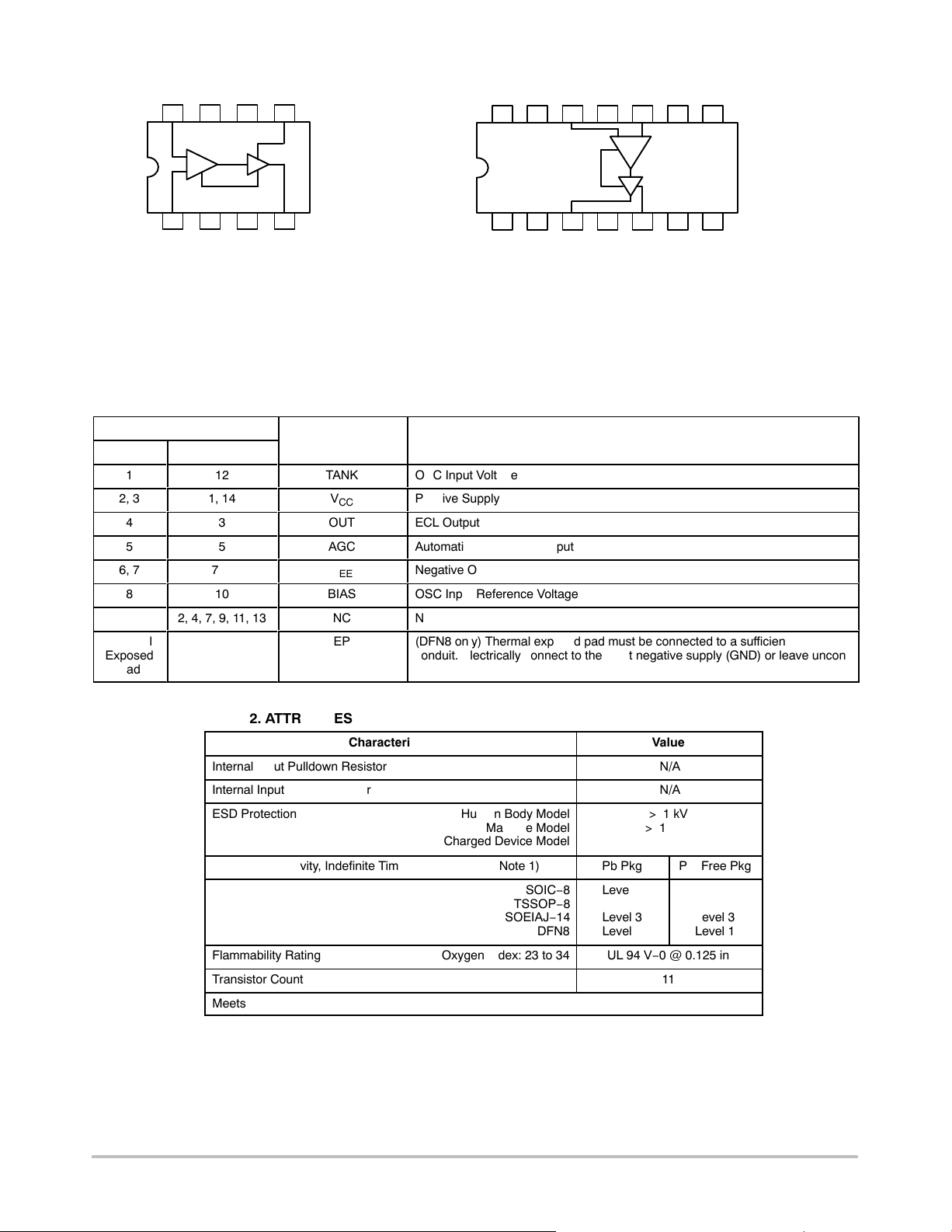
MARKING
DIAGRAMS*
8
8
1
8
1
14
1
A = Assembly Location
L = Wafer Lot
Y = Year
W = Work Week
M
G or G = Pb−Free Package
(Note: Microdot may be in either location)
*For additional marking information, refer to
Application Note AND8002/D.
SOIC−8
D SUFFIX
CASE 751
1
8
TSSOP−8
DT SUFFIX
CASE 948R
1
14
SOEIAJ−14
M SUFFIX
CASE 965
1
DFN8
MN SUFFIX
CASE 506AA
= Date Code
K1648
ALYW
G
1648
ALYWG
G
KEL1648
ALYWG
G
6L M G
14
V
Figure 1. Logic Diagram
© Semiconductor Components Industries, LLC, 2008
August, 2008 − Rev. 8
EE
V
EE
AGC
See detailed ordering and shipping information in the package
dimensions section on page 12 of this data sheet.
1 Publication Order Number:
ORDERING INFORMATION
MC100EL1648/D
BIAS
MC100EL1648
V
EE
AGC
V
EE
568
NC TANK NC BIAS NC V
V
CC
1314 12 11 10 9 8
EE
12374
VCCV
TANK
CC
8 Lead
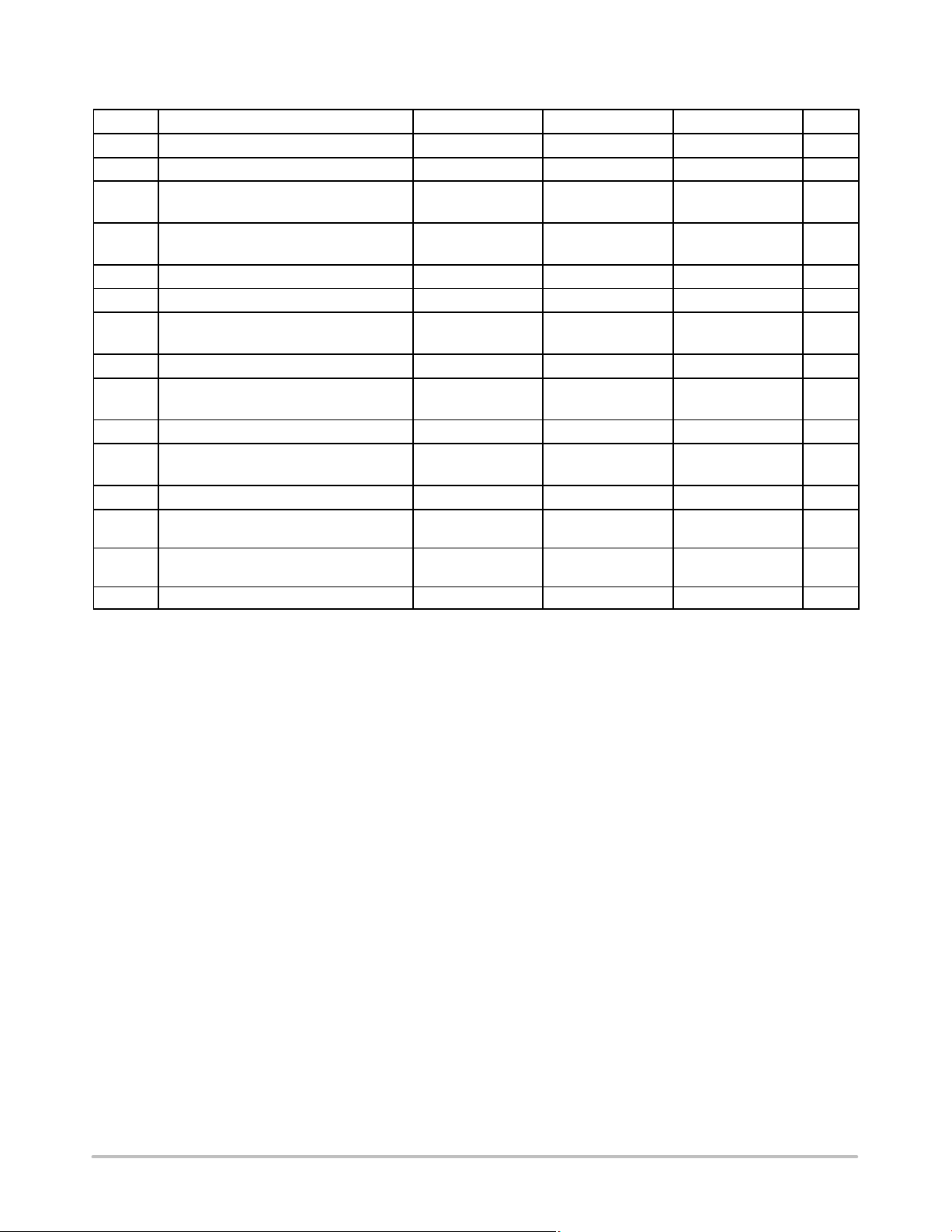
Table 1. PIN DESCRIPTION
Pin No.
8 Lead 14 Lead
1
2, 3
4
5
6, 7
8
Thermal
Exposed
Pad
12
1, 14
3
5
7, 8
10
2, 4, 7, 9, 11, 13
21 34567
OUT
VCCNC OUT NC AGC NC V
Warning: All VCC and VEE pins must be externally connected
to Power Supply to guarantee proper operation.
Figure 2. Pinout Assignments
Symbol Description
TANK
V
CC
OUT
AGC
V
EE
BIAS
NC
EP
OSC Input Voltage
Positive Supply
ECL Output
Automatic Gain Control Input
Negative Output
OSC Input Reference Voltage
No Connect
(DFN8 only) Thermal exposed pad must be connected to a sufficient thermal
conduit. Electrically connect to the most negative supply (GND) or leave unconnected, floating open.
EE
14 Lead
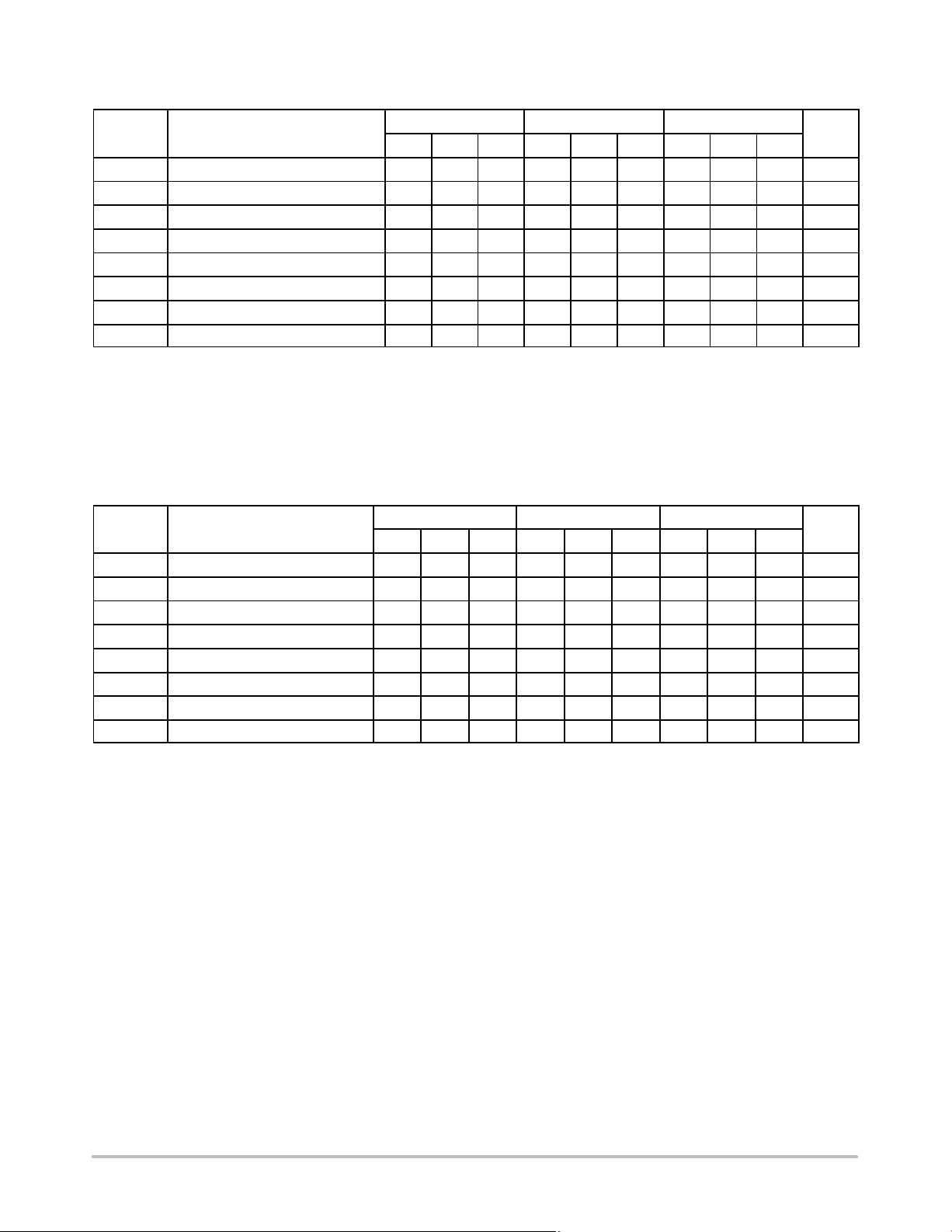
Table 2. ATTRIBUTES
Characteristic Value
Internal Input Pulldown Resistor N/A
Internal Input Pullup Resistor N/A
ESD Protection Human Body Model
Machine Model
Charged Device Model
> 1 kV
> 100 V
> 1 kV
Moisture Sensitivity, Indefinite Time Out of Drypack (Note 1) Pb Pkg Pb−Free Pkg
SOIC−8
TSSOP−8
SOEIAJ−14
DFN8
Level 1
Level 1
Level 3
Level 1
Level 1
Level 3
Level 3
Level 1
Flammability Rating Oxygen Index: 23 to 34 UL 94 V−0 @ 0.125 in
Transistor Count 11
Meets or Exceeds JEDEC Standard EIA/JESD78 IC Latchup Test
1. For additional Moisture Sensitivity information, refer to Application Note AND8003/D.
http://onsemi.com
2
MC100EL1648
Table 3. MAXIMUM RATINGS
Symbol Parameter Condition 1 Condition 2 Rating Unit
V
CC
V
EE
V
I
I
out
T
A
T
stg
q
JA
q
JC
q
JA
q
JC
q
JA
q
JC
q
JA
T
sol
q
JC
Stresses exceeding Maximum Ratings may damage the device. Maximum Ratings are stress ratings only. Functional operation above the
Recommended Operating Conditions is not implied. Extended exposure to stresses above the Recommended Operating Conditions may affect
device reliability.
Power Supply PECL Mode VEE = 0 V 7 to 0 V
Power Supply NECL Mode VCC = 0 V −7 to 0 V
PECL Mode Input Voltage
NECL Mode Input Voltage
Output Current Continuous
VEE = 0 V
V
= 0 V
CC
Surge
VI V
VI V
CC
EE
6 to 0
−6 to 0
50
100
V
V
mA
mA
Operating Temperature Range −40 to +85 °C
Storage Temperature Range −65 to +150 °C
Thermal Resistance (Junction−to−Ambient) 0 lfpm
500 lfpm
SOIC−8
SOIC−8
190
130
°C/W
°C/W
Thermal Resistance (Junction−to−Case) Standard Board SOIC−8 41 to 44 °C/W
Thermal Resistance (Junction−to−Ambient) 0 lfpm
500 lfpm
TSSOP−8
TSSOP−8
185
140
°C/W
°C/W
Thermal Resistance (Junction−to−Case) Standard Board TSSOP−8 41 to 44 °C/W
Thermal Resistance (Junction−to−Ambient) 0 lfpm
500 lfpm
SOIC−14
SOIC−14
150
110
°C/W
°C/W
Thermal Resistance (Junction−to−Case) Standard Board SOIC−14 41 to 44 °C/W
Thermal Resistance (Junction−to−Ambient) 0 lfpm
500 lfpm
Wave Solder Pb
Pb−Free
<2 to 3 sec @ 248°C
<2 to 3 sec @ 260°C
DFN8
DFN8
129
84
265
265
°C/W
°C/W
°C
Thermal Resistance (Junction−to−Case) (Note 1) DFN8 35 to 40 °C/W
http://onsemi.com
3
MC100EL1648
Table 4. PECL DC CHARACTERISTICS V
= 5.0 V; V
CC
= 0.0 V +0.8 / −0.5 V (Note 2)
EE
−40°C 25°C 85°C
Symbol
I
EE
V
OH
V
OL
Characteristic
Power Supply Current 13 19 25 13 19 25 13 19 25 mA
Output HIGH Voltage (Note 3) 3950 4170 4610 3950 4170 4610 3950 4170 4610 mV
Output LOW Voltage (Note 3) 3040 3410 3600 3040 3410 3600 3040 3410 3600 mV
Min Ty p Max Min Ty p Max Min Typ Max
Unit
AGC Automatic Gain Control Input 1690 1980 1690 1980 1690 1980 mV
V
V
V
I
BIAS
IL
IH
L
Bias Voltage (Note 4) 1650 1800 1650 1800 1650 1800 mV
1.5 1.35 1.2 V
2.0 1.85 1.7 V
Input Current −5.0 −5.0 −5.0 mA
NOTE: Device will meet the specifications after thermal equilibrium has been established when mounted in a test socket or printed circuit
board with maintained transverse airflow greater than 500 lfpm. Electrical parameters are guaranteed only over the declared
operating temperature range. Functional operation of the device exceeding these conditions is not implied. Device specification limit
values are applied individually under normal operating conditions and not valid simultaneously.
2. Output parameters vary 1:1 with V
3. 1.0 MW impedance.
CC
.
4. This measurement guarantees the dc potential at the bias point for purposes of incorporating a varactor tuning diode at this point.
Table 5. NECL DC CHARACTERISTICS V
= 0.0 V; V
CC
= −5.0 V +0.8 / −0.5 V (Note 5)
EE
−40°C 25°C 85°C
Symbol
I
EE
V
OH
V
OL
Characteristic
Power Supply Current 13 19 25 13 19 25 13 19 25 mA
Output HIGH Voltage (Note 6) −1050 −830 −399 −1050 −830 −399 −1050 −830 −399 mV
Output LOW Voltage (Note 6) −1960 −1590 −1400 −1960 −1590 −1400 −1960 −1590 −1400 mV
Min Ty p Max Min Typ Max Min Typ Max
Unit
AGC Automatic Gain Control Input −3310 −3020 −3310 −3020 −3310 −3020 mV
V
V
V
I
BIAS
IL
IH
L
Bias Voltage (Note 7) −3350 −3200 −3350 −3200 −3350 −3200 mV
−3.5 −3.65 −3.8 V
−3.0 −3.15 −3.3 V
Input Current −5.0 −5.0 −5.0 mA
NOTE: Device will meet the specifications after thermal equilibrium has been established when mounted in a test socket or printed circuit
board with maintained transverse airflow greater than 500 lfpm. Electrical parameters are guaranteed only over the declared
operating temperature range. Functional operation of the device exceeding these conditions is not implied. Device specification limit
values are applied individually under normal operating conditions and not valid simultaneously.
5. Output parameters vary 1:1 with V
6. 1.0 MW impedance.
CC
.
7. This measurement guarantees the dc potential at the bias point for purposes of incorporating a varactor tuning diode at this point.
http://onsemi.com
4
MC100EL1648
GENERIC TEST CIRCUITS: Bypass to Supply Opposite GND
V
CC
0.1 mF0.1 mF
V
IN
1 KW
0.1mF
Test Point
Tank #1
Tank #2
8 (10)
C
*
1 (12)
V
EE
3 (1) 2 (14)
L
F
4 (3)
OUT
**
L = Micro Metal torroid #T20−22, 8 turns #30
Enameled Copper wire (@ 40 nH)
5 (5)6 (7) 7 (8)
C = MMBV609
* Use high impedance probe (>1.0 MW must be
used).
0.1 mF 0.1 mF0.01 mF100 mF
** The 1200 W resistor and the scope termination
impedance constitute a 25:1 attenuator probe.
Coax shall be CT−070−50 or equivalent.
8 pin (14 pin) Lead Package
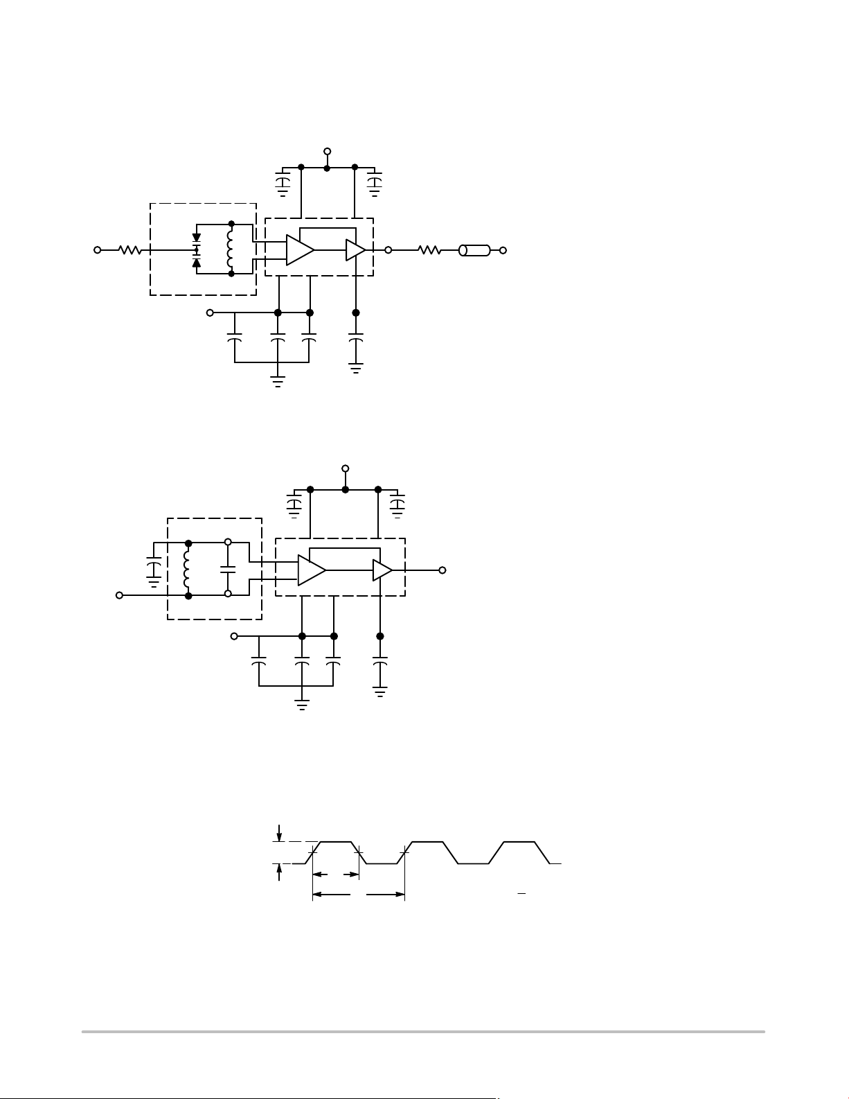
Tank Circuit Option #1, Varactor Diode
V
CC
0.1 mF0.1 mF
8 (10)
3 (1) 2 (14)
L = Micro Metal torroid #T20−22, 8 turns #30
Enameled Copper wire (@ 40 nH)
4 (3)
L
C
F
1 (12)
V
EE
5 (5)6 (7) 7 (8)
C = 3.0−35pF Variable Capacitance (@ 10 pF)
OUT
Note 1 Capacitor for tank may be variable type.
(See Tank Circuit #3.)
Note 2 Use high impedance probe (> 1 MW ).
8 pin (14 pin) Lead Package
0.1 mF 0.1 mF0.01 mF100 mF
Tank Circuit Option #2, Fixed LC
Figure 3. Typical Test Circuit with Alternate Tank Circuits
V
P-P
50%
t
a
t
b
PRF = 1.0MHz
Duty Cycle (Vdc) -
t
a
t
b
Figure 4. Output Waveform
http://onsemi.com
5
MC100EL1648
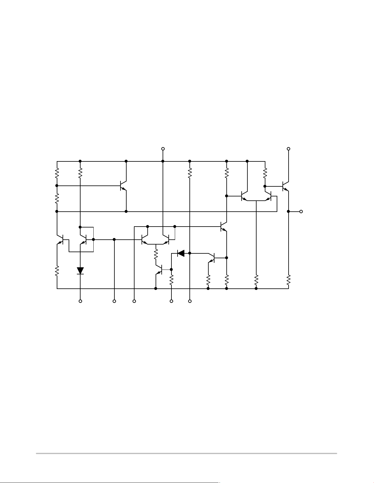
OPERATION THEORY
Figure 5 illustrates the simplified circuit schematic for the
MC100EL1648. The oscillator incorporates positive feedback
by coupling the base of transistor Q6 to the collector of Q7. An
automatic gain control (AGC) is incorporated to limit the
current through the emitter−coupled pair of transistors (Q7 and
Q6) and allow optimum frequency response of the oscillator.
In order to maintain the high quality factor (Q) on the oscillator,
and provide high spectral purity at the output, transistor Q4 is
used to translate the oscillator signal to the output differential
pair Q2 and Q3. Figure 16 indicates the high spectral purity
of the oscillator output (pin 4 on 8−pin SOIC). Transistors
V
2 (14) 3 (1)
CC
800 W 1.36 KW
Q9
1.6 KW
Q2 and Q3, in conjunction with output transistor Q1,
provide a highly buffered output that produces a square
wave. The typical output waveform can be seen in Figure 4.
The bias drive for the oscillator and output buffer is provided
by Q9 and Q11 transistors. In order to minimize current, the
output circuit is realized as an emitter−follower buffer with
an on chip pull−down resistor R
3.1 KW
660 W 167 W
Q3 Q2
Q4
.
E
V
CC
Q1
OUTPUT
4 (3)
400 W
Q10Q11
D2
EE
TANKBIASV
Q7 Q6
330 W
Q8
EE
1 (12) 5 (5)8 (10)7 (8) 6 (7)
D1
16 KW
Q5
82 W 400 W 660 W 510 W
AGCV
8 pin (14 pin) Lead Package
Figure 5. Circuit Schematic
http://onsemi.com
6

30
25
MC100EL1648
Measured Frequency (MHz)
Calculated Frequency (MHz)
20
15
10
FREQUENCY (MHz)
5
0
0 300 500 1000 2000 10000
CAPACITANCE (pF)
0.1mF
Figure 6. Low Frequency Plot
Tank #3
L = Micro Metal torroid #T20−22, 8 turns #30
Enameled Copper wire (@ 40 nH)
C = 3.0−35 pF Variable Capacitance (@ 10 pF)
* The 1200 W resistor and the scope termination
impedance constitute a 25:1 attenuator probe.
Coax shall be CT−070−50 or equivalent.
8 pin (14 pin) Lead Package
10mF0.1mF
8 (10)
L
C
1 (12)
V
EE
3(1)2 (14)
1200*
4 (3)
5 (5)6 (7) 7 (8)
0.1 mF 0.1 mF0.01 mF100 mF
SIGNAL
UNDER
TEST
100
80
60
40
FREQUENCY (MHZ)
20
0
0 0.2 0.3 300
Measured Frequency (MHz)
Calculated Frequency (MHz)
CAPACITANCE (pF)
0.1mF
Tank #3
L = Micro Metal torroid #T20−22, 8 turns #30
Enameled Copper wire (@ 40 nH)
C = 3.0−35 pF Variable Capacitance (@ 10 pF)
* The 1200 W resistor and the scope termination
impedance constitute a 25:1 attenuator probe.
Coax shall be CT−070−50 or equivalent.
8 pin (14 pin) Lead Package
8 (10)
L
C
1 (12)
V
EE
3(1)2 (14)
4 (3)
5 (5)6 (7) 7 (8)
0.1 mF 0.1 mF0.01 mF100 mF
10mF0.1mF
1200*
SIGNAL
UNDER
TEST
Figure 7. High Frequency Plot
http://onsemi.com
7

MC100EL1648
F
FIXED FREQUENCY MODE
The MC100EL1648 external tank circuit components are
used to determine the desired frequency of operation as
shown in Figure 8, tank option #2. The tank circuit
components have direct impact on the tuning sensitivity, I
EE
and phase noise performance. Fixed frequency of the tank
circuit is usually realized by an inductor and capacitor (LC
network) that contains a high Quality factor (Q). The plotted
curve indicates various fixed frequencies obtained with a
single inductor and variable capacitor. The Q of the
components in the tank circuit has a direct impact on the
resulting phase noise of the oscillator. In general, when the
Q is high the oscillator will result in lower phase noise.
570
470
370
270
170
FREQUENCY (MHz)
70
0
−30
0.3 300 500 1000 2000 10000
0.1 mF
Test
Point
L = Micro Metal torroid #T20−22, 8 turns #30
C = 3.0−35 pF Variable Capacitance (@ 10 pF)
Note 1 Capacitor for tank may be variable type.
(See Tank Circuit #3.)
Note 2 Use high impedance probe (> 1 MW ).
8 pin (14 pin) lead package
Q
L
Tank #2
V
EE
Enameled Copper wire (@ 40 nH)
≥ 100
L
Measured Frequency (MHz)
Calculated Frequency (MHz)
CAPACITANCE (pF)
V
CC
0.1 mF 0.1 m
8 (10)
1 (12)
3 (1) 2 (14)
C
0.1 mF 0.1 mF0.01 mF100 mF
4 (3)
F
OUT
5 (5)6 (7) 7 (8)
Figure 8. Fixed Frequency LC Tank
Only high quality surface−mount RF chip capacitors
should be used in the tank circuit at high frequencies. These
capacitors should have very low dielectric loss (high−Q). At
a minimum, the capacitors selected should be operating at
100 MHz below their series resonance point. As the desired
frequency of operation increases, the values of the tank
,
capacitor will decrease since the series resonance point is a
function of the capacitance value. Typically, the inductor is
realized as a surface−mount chip or a wound coil. In
addition, the lead inductance and board inductance and
capacitance also have an impact on the final operating point.
The following equation will help to choose the appropriate
values for your tank circuit design.
f
0 +
1
Ǹ
2p LT*C
T
Where LT = Total Inductance
C
= Total Capacitance
T
Figure 9 and Figure 10 represent the ideal curve of
inductance/capacitance versus frequency with one known
tank component. This helps the designer of the tank circuit
to choose desired value of inductor/capacitor component for
the wanted frequency. The lead inductance and board
inductance and capacitance will also have an impact on the
tank component values (inductor and capacitor).
50
45
40
35
30
25
20
INDUCTANCE (nH)
15
10
5
0
50
45
40
35
30
25
20
CAPACITANCE (F)
15
10
5
0
Inductance vs. Frequency with 5 pF Cap
700 1000 1300 160400
FREQUENCY (MHz)
Figure 9. Capacitor Value Known (5 pF)
Capacitance vs. Frequency with 4 nH Inductance
700 1000 1300 160400
FREQUENCY
(Hz)
Figure 10. Inductor Value Known (4 nH)
http://onsemi.com
8

MC100EL1648
0
VOLTAGE CONTROLLED MODE
The tank circuit configuration presented in Figure 11,
Voltage Controlled Varactor Mode, allows the VCO to be
tuned across the full operating voltage of the power supply.
Deriving from Figure 6, the tank capacitor, C, is replaced
with a varactor diode whose capacitance changes with the
voltage applied, thus changing the resonant frequency at
which the VCO tank operates as shown in Figure 3, tank
option #1. The capacitive component in Equation 1 also
needs to include the input capacitance of the device and
other circuit and parasitic elements.
190
170
150
130
110
90
FREQUENCY (MHz)
70
50
024681
Vin, INPUT VOLTAGE (V)
Figure 12. Plot 1. Dual Varactor MMBV609,
V
vs. Frequency
IN
V
CC
When operating the oscillator in the voltage controlled
mode with Tank Circuit #1 (Figure 3), it should be noted that
the cathode of the varactor diode (D), pin 8 (for 8 lead
package) or pin 10 (for 14 lead package) should be biased at
least 1.4 V above V
EE
.
Typical transfer characteristics employing the
capacitance of the varactor diode (plus the input capacitance
of the device, about 6.0 pF typical) in the voltage controlled
mode is shown in Plot 1, Dual Varactor MMBV609 V
vs.
in
Frequency. Figure 6, Figure 7, and Figure 8 show the
accuracy of the measured frequency with the different
variable capacitance values. The 1.0 kW resistor in Figure 11
is used to protect the varactor diode during testing. It is not
necessary as long as the dc input voltage does not cause the
diode to become forward biased. The tuning range of the
oscillator in the voltage controlled mode may be calculated
as follows:
Ǹ
f
max
f
min
CD(max) ) C
+
Ǹ
CD(min) ) C
S
S
Where
f
min
+
2p
Ǹ
1
ǒ
L(CD(max) ) C
Ǔ
S
Where
C
= Shunt Capacitance (input plus external
S
capacitance)
0.1 mF0.1 mF
8 (10)
V
IN
C
1 KW
Tank #1
*Use high impedance probe (>1.0 MegW must be used).
**The 1200 W resistor and the scope termination imped-
ance constitute a 25:1 attenuator probe. Coax shall be
CT−070−50 or equivalent.
L = Micro Metal torroid #T20−22, 8 turns #30
Enameled Copper wire (@ 40 nH)
C = MMBV609
8 pin (14 pin) lead package
Figure 11. Voltage Controlled Varactor Mode
1 (12)
V
EE
3 (1) 2 (14)
L
*
0.1 mF 0.1 mF0.01 mF100 mF
C
= Varactor Capacitance as a function of bias
D
voltage
Good RF and low−frequency bypassing is necessary on
4 (3)
the device power supply pins. Capacitors on the AGC pin
and the input varactor trace should be used to bypass the
AGC point and the VCO input (varactor diode),
guaranteeing only dc levels at these points. For output
5 (5)6 (7) 7 (8)
**
F
OUT
frequency operation between 1.0 MHz and 50 MHz, a 0.1 mF
capacitor is sufficient. At higher frequencies, smaller values
of capacitance should be used; at lower frequencies, larger
values of capacitance. At high frequencies, the value of
bypass capacitors depends directly on the physical layout of
the system. All bypassing should be as close to the package
pins as possible to minimize unwanted lead inductance.
Several different capacitors may be needed to bypass
various frequencies.
http://onsemi.com
9

MC100EL1648
WAVE−FORM CONDITIONING − SINE OR SQUARE WAVE
The peak−to−peak swing of the tank circuit is set
internally by the AGC pin. Since the voltage swing of the
tank circuit provides the drive for the output buffer, the AGC
potential directly affects the output waveform. If it is desired
to have a sine wave at the output of the MC100EL1648, a
series resistor is tied from the AGC point to the most
negative power potential (ground if positive volt supply is
used, −5.2 V if a negative supply is used) as shown in
+5.0Vdc
114
10
12
78
Figure 13. Method of Obtaining a Sine−Wave Output
Output
3
5
Figure 13. At frequencies above 100 MHz typical, it may be
desirable to increase the tank circuit peak−to−peak voltage
in order to shape the signal into a more square waveform at
the output of the MC100EL1648. This is accomplished by
tying a series resistor (1.0 kW minimum) from the AGC to
the most positive power potential (+5.0 V if a positive volt
supply is used, ground if a −5.2 V supply is used). Figure 14
illustrates this principle.
+5.0Vdc
114
10
12
78
Figure 14. Method of Extending the Useful Range
of the MC100EL1648 (Square Wave Output)
3
5
Output
1.0k min
http://onsemi.com
10

0.1 mF
Tank #3
MC100EL1648
SPECTRAL PURITY
10 dB / DEC
99.8 99.9 100.0 100.1 100.2
B.W. = 10 kHz, Center Frequency = 100 MHz
Scan Width = 50 kHz/div, Vertical Scale = 10 dB/div
Figure 15. Spectral Purity
10 mF0.1 mF
8 (10)
L
C
1 (12)
V
EE
6 (7) 7 (8)
3(1)2 (14)
1200*
4 (3)
5 (5)
0.1 mF 0.1 mF0.01 mF100 mF
SIGNAL
UNDER
TEST
L = Micro Metal torroid #T20−22, 8 turns #30
Enameled Copper wire (@ 40 nH)
C = 3.0−35 pF Variable Capacitance (@ 10 pF)
** The 1200 W resistor and the scope termination
impedance constitute a 25:1 attenuator probe.
Coax shall be CT−070−50 or equivalent.
8 pin (14 pin) Lead Package
Spectral Purity Test Circuit
Figure 16. Spectral Purity of Signal Output for 200 MHz Testing
Zo = 50 W
Zo = 50 W
50 W 50 W
V
VTT = VCC − 2.0 V
TT
Receiver
Device
Driver
Device
QD
Q D
Figure 17. Typical Termination for Output Driver and Device Evaluation
(See Application Note AND8020/D − Termination of ECL Logic Devices.)
http://onsemi.com
11

MC100EL1648
ORDERING INFORMATION
Device Package Shipping
MC100EL1648D SOIC−8, Narrow Body 98 Units / Rail
MC100EL1648DG SOIC−8, Narrow Body
(Pb−Free)
MC100EL1648DR2 SOIC−8, Narrow Body 2500 / Tape & Reel
MC100EL1648DR2G SOIC−8, Narrow Body
(Pb−Free)
MC100EL1648DT TSSOP−8 100 Units / Rail
MC100EL1648DTG TSSOP−8
(Pb−Free)
MC100EL1648DTR2 TSSOP−8 2500 / Tape & Reel
MC100EL1648DTR2G TSSOP−8
(Pb−Free)
MC100EL1648M SOEAIJ−14 50 Units / Rail
MC100EL1648MG SOEAIJ−14
(Pb−Free)
MC100EL1648MEL SOEAIJ−14 2000 / Tape & Reel
MC100EL1648MELG SOEAIJ−14
(Pb−Free)
MC100EL1648MNR4 DFN8 1000 / Tape & Reel
MC100EL1648MNR4G DFN8
(Pb−Free)
†For information on tape and reel specifications, including part orientation and tape sizes, please refer to our Tape and Reel Packaging
Specifications Brochure, BRD8011/D.
98 Units / Rail
2500 / Tape & Reel
100 Units / Rail
2500 / Tape & Reel
50 Units / Rail
2000 / Tape & Reel
1000 / Tape & Reel
†
Resource Reference of Application Notes
AN1405/D − ECL Clock Distribution Techniques
AN1406/D − Designing with PECL (ECL at +5.0 V)
AN1503/D −
AN1504/D − Metastability and the ECLinPS Family
AN1568/D − Interfacing Between LVDS and ECL
AN1672/D − The ECL Translator Guide
AND8001/D − Odd Number Counters Design
AND8002/D − Marking and Date Codes
AND8020/D − Termination of ECL Logic Devices
AND8066/D − Interfacing with ECLinPS
AND8090/D − AC Characteristics of ECL Devices
ECLinPSt I/O SPiCE Modeling Kit
http://onsemi.com
12

−Y−
−Z−
MC100EL1648
PACKAGE DIMENSIONS
SOIC−8 NB
CASE 751−07
ISSUE AH
NOTES:
−X−
A
58
B
1
S
0.25 (0.010)
4
M
M
Y
K
G
C
SEATING
PLANE
0.10 (0.004)
H
D
0.25 (0.010) Z
M
Y
SXS
N
X 45
_
M
J
1. DIMENSIONING AND TOLERANCING PER
ANSI Y14.5M, 1982.
2. CONTROLLING DIMENSION: MILLIMETER.
3. DIMENSION A AND B DO NOT INCLUDE
MOLD PROTRUSION.
4. MAXIMUM MOLD PROTRUSION 0.15 (0.006)
PER SIDE.
5. DIMENSION D DOES NOT INCLUDE DAMBAR
PROTRUSION. ALLOWABLE DAMBAR
PROTRUSION SHALL BE 0.127 (0.005) TOTAL
IN EXCESS OF THE D DIMENSION AT
MAXIMUM MATERIAL CONDITION.
6. 751−01 THRU 751−06 ARE OBSOLETE. NEW
STANDARD IS 751−07.
MILLIMETERS
DIMAMIN MAX MIN MAX
4.80 5.00 0.189 0.197
B 3.80 4.00 0.150 0.157
C 1.35 1.75 0.053 0.069
D 0.33 0.51 0.013 0.020
G 1.27 BSC 0.050 BSC
H 0.10 0.25 0.004 0.010
J 0.19 0.25 0.007 0.010
K 0.40 1.27 0.016 0.050
M 0 8 0 8
____
N 0.25 0.50 0.010 0.020
S 5.80 6.20 0.228 0.244
INCHES
SOLDERING FOOTPRINT*
1.52
0.060
7.0
0.275
0.6
0.024
*For additional information on our Pb−Free strategy and soldering
details, please download the ON Semiconductor Soldering and
Mounting Techniques Reference Manual, SOLDERRM/D.
4.0
0.155
1.270
0.050
SCALE 6:1
mm
ǒ
inches
Ǔ
http://onsemi.com
13

MC100EL1648
PACKAGE DIMENSIONS
TSSOP−8
DT SUFFIX
PLASTIC TSSOP PACKAGE
CASE 948R−02
ISSUE A
0.10 (0.004)
−T−
SEATING
PLANE
8x REFK
S
U0.15 (0.006) T
2X L/2
85
L
PIN 1
IDENT
S
U0.15 (0.006) T
0.10 (0.004) V
1
−U−
4
A
M
B
−V−
S
U
T
S
0.25 (0.010)
M
F
DETAIL E
C
D
G
DETAIL E
−W−
NOTES:
1. DIMENSIONING AND TOLERANCING PER ANSI
Y14.5M, 1982.
2. CONTROLLING DIMENSION: MILLIMETER.
3. DIMENSION A DOES NOT INCLUDE MOLD FLASH.
PROTRUSIONS OR GATE BURRS. MOLD FLASH
OR GATE BURRS SHALL NOT EXCEED 0.15
(0.006) PER SIDE.
4. DIMENSION B DOES NOT INCLUDE INTERLEAD
FLASH OR PROTRUSION. INTERLEAD FLASH OR
PROTRUSION SHALL NOT EXCEED 0.25 (0.010)
PER SIDE.
5. TERMINAL NUMBERS ARE SHOWN FOR
REFERENCE ONLY.
6. DIMENSION A AND B ARE TO BE DETERMINED
AT DATUM PLANE -W-.
DIM MIN MAX MIN MAX
A 2.90 3.10 0.114 0.122
B 2.90 3.10 0.114 0.122
C 0.80 1.10 0.031 0.043
D 0.05 0.15 0.002 0.006
F 0.40 0.70 0.016 0.028
G 0.65 BSC 0.026 BSC
K 0.25 0.40 0.010 0.016
L 4.90 BSC 0.193 BSC
M 0 6 0 6
____
INCHESMILLIMETERS
http://onsemi.com
14

14 8
1
Z
D
e
b
0.13 (0.005)
M
E
7
A
0.10 (0.004)
H
A
1
E
VIEW P
MC100EL1648
PACKAGE DIMENSIONS
SOEIAJ−14
CASE 965−01
ISSUE A
L
E
Q
1
_
M
L
DETAIL P
c
NOTES:
1. DIMENSIONING AND TOLERANCING PER ANSI
Y14.5M, 1982.
2. CONTROLLING DIMENSION: MILLIMETER.
3. DIMENSIONS D AND E DO NOT INCLUDE
MOLD FLASH OR PROTRUSIONS AND ARE
MEASURED AT THE PARTING LINE. MOLD FLASH
OR PROTRUSIONS SHALL NOT EXCEED 0.15
(0.006) PER SIDE.
4. TERMINAL NUMBERS ARE SHOWN FOR
REFERENCE ONLY.
5. THE LEAD WIDTH DIMENSION (b) DOES NOT
INCLUDE DAMBAR PROTRUSION. ALLOWABLE
DAMBAR PROTRUSION SHALL BE 0.08 (0.003)
TOTAL IN EXCESS OF THE LEAD WIDTH
DIMENSION AT MAXIMUM MATERIAL CONDITION.
DAMBAR CANNOT BE LOCATED ON THE LOWER
RADIUS OR THE FOOT. MINIMUM SPACE
BETWEEN PROTRUSIONS AND ADJACENT LEAD
TO BE 0.46 ( 0.018).
MILLIMETERS
DIM MIN MAX MIN MAX
--- 2.05 --- 0.081
A
A
0.05 0.20 0.002 0.008
1
0.35 0.50 0.014 0.020
b
0.10 0.20 0.004 0.008
c
9.90 10.50 0.390 0.413
D
5.10 5.45 0.201 0.215
E
1.27 BSC 0.050 BSC
e
H
7.40 8.20 0.291 0.323
E
0.50 0.85 0.020 0.033
0.50
L
1.10 1.50 0.043 0.059
E
0
M
_
Q
0.70 0.90 0.028 0.035
1
--- 1.42 --- 0.056
Z
INCHES
10
_
10
0
_
_
http://onsemi.com
15

MC100EL1648
PACKAGE DIMENSIONS
DFN8
CASE 506AA−01
ISSUE D
8 X
REFERENCE
2 X
SEATING
PLANE
PIN ONE
2 X
C0.10
C0.08
C0.10
A1
8 X
D
A
B
E
C0.10
TOP VIEW
NOTES:
1. DIMENSIONING AND TOLERANCING PER
ASME Y14.5M, 1994 .
2. CONTROLLING DIMENSION: MILLIMETERS.
3. DIMENSION b APPLIES TO PLATED
TERMINAL AND IS MEASURED BETWEEN
0.25 AND 0.30 MM FROM TERMINAL.
4. COPLANARITY APPLIES TO THE EXPOSED
PAD AS WELL AS THE TERMINALS.
MILLIMETERS
DIM MIN MAX
A 0.80 1.00
A1 0.00 0.05
A3 0.20 REF
b 0.20 0.30
D 2.00 BSC
D2 1.10 1.30
E 2.00 BSC
E2 0.70 0.90
e 0.50 BSC
K 0.20 −−−
L 0.25 0.35
A
SIDE VIEW
(A3)
C
D2
e/2
1
e
4
L
E2
K
8
5
8 X
0.10 C
b
0.05 C
A
BB
NOTE 3
BOTTOM VIEW
ECLinPS is a trademark of Semiconductor Components INdustries, LLC (SCILLC).
ON Semiconductor and are registered trademarks of Semiconductor Components Industries, LLC (SCILLC). SCILLC reserves the right to make changes without further notice
to any products herein. SCILLC makes no warranty, representation or guarantee regarding the suitability of its products for any particular purpose, nor does SCILLC assume any liability
arising out of the application or use of any product or circuit, and specifically disclaims any and all liability, including without limitation special, consequential or incidental damages.
“Typical” parameters which may be provided in SCILLC data sheets and/or specifications can and do vary in different applications and actual performance may vary over time. All
operating parameters, including “Typicals” must be validated for each customer application by customer’s technical experts. SCILLC does not convey any license under its patent rights
nor the rights of others. SCILLC products are not designed, intended, or authorized for use as components in systems intended for surgical implant into the body, or other applications
intended to support or sustain life, or for any other application in which the failure of the SCILLC product could create a situation where personal injury or death may occur. Should
Buyer purchase or use SCILLC products for any such unintended or unauthorized application, Buyer shall indemnify and hold SCILLC and its officers, employees, subsidiaries, affiliates,
and distributors harmless against all claims, costs, damages, and expenses, and reasonable attorney fees arising out of, directly or indirectly, any claim of personal injury or death
associated with such unintended or unauthorized use, even if such claim alleges that SCILLC was negligent regarding the design or manufacture of the part. SCILLC is an Equal
Opportunity/Affirmative Action Employer. This literature is subject to all applicable copyright laws and is not for resale in any manner.
PUBLICATION ORDERING INFORMATION
LITERATURE FULFILLMENT:
Literature Distribution Center for ON Semiconductor
P.O. Box 5163, Denver, Colorado 80217 USA
Phone: 303−675−2175 or 800−344−3860 Toll Free USA/Canada
Fax: 303−675−2176 or 800−344−3867 Toll Free USA/Canada
Email: orderlit@onsemi.com
N. American Technical Support: 800−282−9855 Toll Free
USA/Canada
Europe, Middle East and Africa Technical Support:
Phone: 421 33 790 2910
Japan Customer Focus Center
Phone: 81−3−5773−3850
http://onsemi.com
ON Semiconductor Website: www.onsemi.com
Order Literature: http://www.onsemi.com/orderlit
For additional information, please contact your local
Sales Representative
MC100EL1648/D
16

 Loading...