

Page 1
ESD4238
PicoGuard[ XS ESD Clamp
Array with ESD Protection
Functional Description
The PicoGuard XS protection family is specifically designed for
next generation deep sub−micron high speed data line protection.
The ESD4238 is ideal for protecting systems with high data and
clock rates or for circuits requiring low capacitive loading and tightly
controlled signal skews (with channel−to−channel matching at 2%
max deviation).
The device is particularly well−suited for protecting systems using
high−speed ports such as DVI or HDMI, along with corresponding
ports in removable storage, digital camcorders, DVD−RW drives and
other applications where extremely low loading capacitance with ESD
protection are required.
The ESD4238 also features easily routed “pass−through” pinouts in
a RoHS−compliant (Pb−Free), 16−lead WDFN, small footprint
package.
Features
• ESD Protection for Four Pairs of Differential Channels
• ESD protection to IEC61000−4−2 Level 4:
♦ $20 kV contact discharge
♦ $25 kV air discharge
• Pass−through Impedance Matched Clamp Architecture
• Flow−through Routing for High−speed Signal Integrity
• 100 W Matched Impedance for Each Paired Differential Channel
• Capacitance Change with Temperature and Voltage
• Each I/O Pin Can Withstand Over 1000 ESD Strikes*
• These Devices are Pb−Free, Halogen Free/BFR Free and are RoHS
Compliant
Applications
• DVI ports, HDMI Ports in Notebooks, Set−top Boxes, Digital TVs,
LCD Displays
• General Purpose High−speed Data Line ESD Protection
http://onsemi.com
16
1
WDFN16
CASE 511AU
MARKING DIAGRAM
238M
G
238 = Specific Device Code
M
G = Pb−Free Package
= Date Code
PIN CONNECTIONS
In_1+
In_1−
In_2+
In_2−
In_3+
In_3−
In_4+
In_4+
1
2
3
4
5
6
7
8
(Top View)
GND
16
15
14
13
12
11
10
9
Out_1+
Out_1−
Out_2+
Out_2−
Out_3+
Out_3−
Out_4+
Out_4−
*Standard test condition is IEC61000−4−2 level 4 test circuit with each pin
subjected to $8 kV contact discharge for 1000 pulses. Discharges are timed
at 1 second intervals and all 1000 strikes are completed in one continuous test
run. The part is then subjected to standard production test to verify that all of the
tested parameters are within spec after the 1000 strikes.
© Semiconductor Components Industries, LLC, 2010
October, 2010 − Rev. 0
ORDERING INFORMATION
See detailed ordering and shipping information in the package
dimensions section on page 7 of this data sheet.
Publication Order Number:
ESD4238/D
Page 2
ESD4238
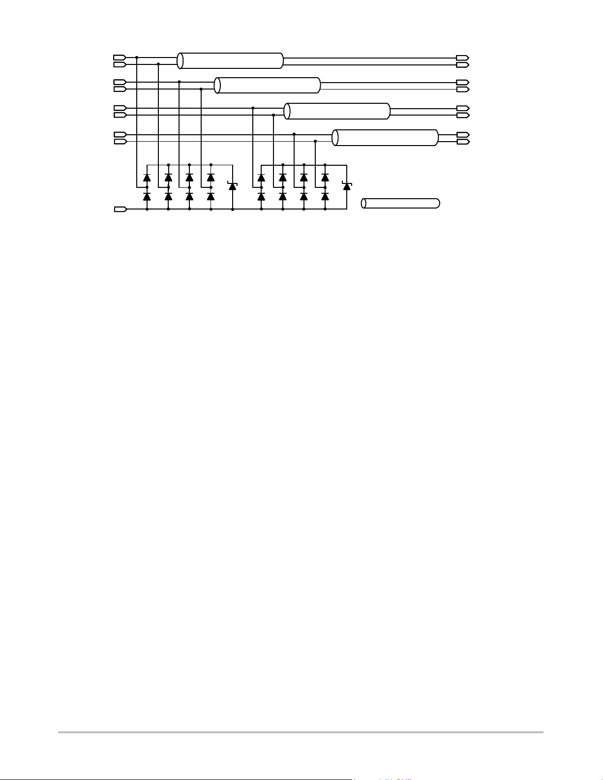
Out_1+
Out_1−
Out_2+
Out_2−
Out_3+
Out_3−
Out_4+
Out_4−
GND
Figure 1. Block Diagram
PicoGuard XS ESD Protection Architecture
Conceptually, an ESD protection device performs the
following actions upon an ESD strike discharge into a
protected ASIC (see Figure 2):
1. When an ESD potential is applied to the system
under test (contact or air−discharge), Kirchoff’s
Current Law (KCL) dictates that the Electrical
Overstress (EOS) currents will immediately divide
throughout the circuit, based on the dynamic
impedance of each path.
2. Ideally, the classic shunt ESD clamp will switch
within 1 ns to a low−impedance path and return
the majority of the EOS current to the chassis
shield/reference ground. In actuality, if the ESD
component’s response time (t
CLAMP
) is slower
than the ASIC it is protecting, or if the Dynamic
Clamping Resistance (RDYN) is not significantly
lower than the ASIC’s I/O cell circuitry, then the
ASIC will have to absorb a large amount of the
EOS energy, and be more likely to fail.
3. Subsequent to the ESD/EOS event, both devices
must immediately return to their original
specifications, and be ready for an additional
strike. Any deterioration in parasitics or clamping
In_1+
In_1−
In_2+
In_2−
In_3+
In_3−
In_4+
In_4+
= 100 W differential
matched characteristic
impedance.
capability should be considered a failure, since it
can then affect signal integrity or subsequent
protection capability. (This is known as
”multi−strike” capability.)
In the ESD4238 PicoGuard XS architecture, the signal
line leading the connector to the ASIC routes through the
ESD4238 chip which provides 100 W matched differential
channel characteristic impedance that helps optimize 100 W
load impedance applications such as the HDMI high speed
data lines.
NOTES: When each of the channels is used individually
for single−ended signal lines protection, the
individual channel provides 50 W characteristic
impedance matching.
The load impedance matching feature of the ESD4238
helps to simplify system designer’s PCB layout
considerations in impedance matching and also eliminates
associated passive components.
The route through the PicoGuard XS architecture enables
the ESD4238 to provide matched impedance for the signal
path between the connector and the ASIC. Besides this
function, this circuit arrangement also changes the way the
parasitic inductance interacts with the ESD protection
circuit and helps reduce the I
RESIDUAL
current to the ASIC.
http://onsemi.com
2
Page 3
ESD Strike
I/O
Connector
I
SHUNT
ESD4238
ESD
ESD
Protection
PROTECTION
Device
DEVICE
I
RESIDUAL
ASIC
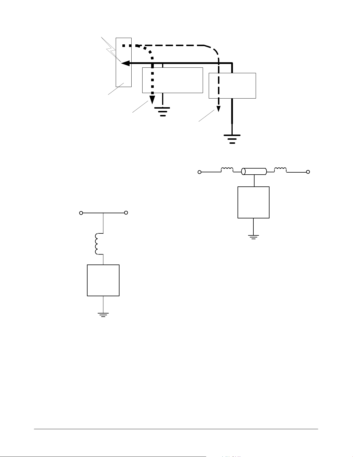
Figure 2. Standard ESD Protection Device Block Diagram
The PicoGuard XS Architecture Advantages
Figure 3 illustrates a standard ESD protection device. The
inductor element represents the parasitic inductance arising
from the bond wire and the PCB trace leading to the ESD
protection diodes.
ASICConnector
Bond Wire
Inductance
ESD
Stage
Figure 3. Standard ESD Protection Model
Figure 4 illustrates one of the channels. Similarly, the
inductor elements represent the parasitic inductance arising
from the bond wire and PCB traces leading to the ESD
protection diodes as well.
Connector ASIC
L1
Figure 4. ESD4238 PicoGuard XS ESD Protection
ESD4238 Inductor Elements
50W
L2
ESD
Device
Model
In the ESD4238 PicoGuard XS architecture, the inductor
elements and ESD protection diodes interact differently
compared to the standard ESD model. In the standard ESD
protection device model, the inductive element presents
high impedance against high slew rate strike voltage, i.e.
during an ESD strike. The impedance increases the
resistance of the conduction path leading to the ESD
protection element. This limits the speed that the ESD pulse
can discharge through the ESD protection element.
In the PicoGuard XS architecture, the inductive elements
are in series to the conduction path leading to the protected
http://onsemi.com
3
Page 4

ESD4238
device. The elements actually help to limit the current and
voltage striking the protected device.
First the reactance of the inductive element, L1, on the
connector side when an ESD strike occurs, acts in the
opposite direction of the ESD striking current. This helps
limit the peak striking voltage. Then the reactance of the
components that help to limit the ESD current strike to the
protected device and also improves the signal integrity of the
system by balancing the capacitive loading effects of the
ESD diodes. At the same time, this architecture provides an
impedance matched signal path for 50 W loading
applications.
inductive element, L2, on the ASIC side forces this limited
ESD strike current to be shunted through the ESD protection
diodes. At the same time, the voltage drop across both series
element acts to lower the clamping voltage at the protected
device terminal.
Through this arrangement, the inductive elements also
tune the impedance of the ESD protection element by
cancelling the capacitive load presented by the ESD diodes
to the signal line. This improves the signal integrity and
makes the overall ESD protection device more transparent
to the high bandwidth data signals passing through the
channel.
The innovative PicoGuard XS architecture turns the
disadvantages of the parasitic inductive elements into useful
PIN DESCRIPTIONS
Pin Name Description
1 In_1+ Bidrectional Clamp to ASIC (inside system)
2 In_1− Bidrectional Clamp to ASIC (inside system)
3 In_2+ Bidrectional Clamp to ASIC (inside system)
4 In_2− Bidrectional Clamp to ASIC (inside system)
5 In_3+ Bidrectional Clamp to ASIC (inside system)
6 In_3− Bidrectional Clamp to ASIC (inside system)
7 In_4+ Bidrectional Clamp to ASIC (inside system)
8 In_4− Bidrectional Clamp to ASIC (inside system)
9 Out_4− Bidrectional Clamp to Connector (outside system)
10 Out_4+ Bidrectional Clamp to Connector (outside system)
11 Out_3− Bidrectional Clamp to Connector (outside system)
12 Out_3+ Bidrectional Clamp to Connector (outside system)
13 Out_2− Bidrectional Clamp to Connector (outside system)
14 Out_2+ Bidrectional Clamp to Connector (outside system)
15 Out_1− Bidrectional Clamp to Connector (outside system)
16 Out_1+ Bidrectional Clamp to Connector (outside system)
PAD GND Ground return to shield
Precision Internal Component Matching
Board designs can take advantage of precision internal
component matching for improved signal integrity, not
otherwise possible with discrete components at the system
level. This simplifies PCB layout considerations and
eliminates associated passive components for load matching
normally required by standard ESD protection circuits.
Each ESD channel consists of a pair of diodes in series
which steer the positive or negative ESD current pulse to
either the Zener diode or to ground. This eliminates the need
for a separate bypass capacitor to absorb positive ESD
strikes. The ESD4238 protects against ESD pulses up to
$20 kV contact per the IEC 61000−4−2 standard.
ABSOLUTE MAXIMUM RATINGS
Parameter
Operating Temperature Range −40 to +85 °C
Storage Temperature Range −65 to +150 °C
Breakdown Voltage (Positive) 6 V
Stresses exceeding Maximum Ratings may damage the device. Maximum Ratings are stress ratings only. Functional operation above the
Recommended Operating Conditions is not implied. Extended exposure to stresses above the Recommended Operating Conditions may affect
device reliability.
http://onsemi.com
4
Rating Unit
Page 5

ESD4238
ELECTRICAL OPERATING CHARACTERISTICS (See Note 1)
Symbol
V
V
I
I
ESD
IN
IN
F
I/O Voltage Relative to GND −0.5 5.5 V
Continuous Current through signal pins (IN to
OUT) 1000 Hr
Channel Leakage Current T
ESD Protection − Peak Discharge Voltage at any
channel input, in system:
a) Contact discharge per
IEC 61000−4−2 Standard
b) Air discharge per IEC 61000−4−2 Standard
I
RES
V
CL
Residual ESD Peak Current on RDUP
(Resistance of Device Under Protection)
Channel Clamp Voltage
(Channel clamp voltage per IEC 61000−4−5
Standard)
Positive Transients
Negative Transients
R
DYN
Dynamic Resistance
Positive Transients
Negative Transients
Zo Differential Channels pair characteristic
impedance
DZo
Channel−to−Channel Impedance Match
(Differential)
Z
CHANNEL
Individual Channel Characteristic Impedance in
Single−ended Connection
Parameter Test Conditions
T
T
IEC 61000−4−2 8 kV;
RDUP = 5 W, T
IPP = 1 A, TA = 25°C,
t
P
IPP = 1 A, TA = 25°C
t
P
TR = 200 ps (Note 2) 100
TR = 200 ps (Note 2) 2 %
TR = 200 ps 50
= 25°C; V
A
= 25°C (Note 2)
A
= 25°C (Note 2)
A
= 0 V, V
N
= 25°C (Note 2)
A
= 8/20 ms (Note 2)
= 8/20 ms (Note 2)
Min Typ Max Unit
100 mA
= 5 V 0.1 1.0
TEST
$20
$25
+10
−1.9
3.8 A
2.0
0.7
mA
kV
kV
V
V
W
W
W
W
DZ
CHANNEL
1. All parameters specified at T
2. This parameter is guaranteed by design and verified by device characterization.
Channel−to−Channel Impedance Match
(Individual)
= –40°C to +85°C unless otherwise noted.
A
TR = 200 ps (Note 2) 2 %
http://onsemi.com
5
Page 6

ESD4238
PERFORMANCE INFORMATION
Graphical Comparison and Test Setup
Figure 5 shows that the ESD4238 lowers the peak voltage
and clamping voltage by more than 60% across a wide range
of loading conditions in comparison to a standard ESD
Figure 5. Normalized V
(8 kV IEC−61000 4−2 ESD Contact Strike) vs. Loading (RDUP)*
Peak
protection device. Figure 6 also indicates that the
DUP/ASIC protected by the ESD4238 dissipates less power
than a standard ESD protection device. This data was
derived using the test setups shown in Figure 7.
Figure 6. Normalized Residual Current into DUP vs. RDUP*
*RDUP is the emulated Dynamic Resistance (load) of the Device Under Protection (DUP). See Figure 7.
http://onsemi.com
6
Page 7

ESD4238
Voltage
IEC 6100 −4−2
Test Standards
Standard
ESD Device
Probe
Current
Probe
Device Under
Protection (DUP)
R
VARIABLE
I
RESIDUAL
Figure 7. Test Setups: Standard Device (Left) and ESD4238 (Right)
ESD4238 Application and Guidelines
As a general rule, the ESD4238 ESD protection array
should be located as close as possible to the point of entry of
Voltage
IEC 6100 −4−2
Test Standards
ESD4238
Probe
Current
Probe
Device Under
Protection (DUP)
R
VARIABLE
I
RESIDUAL
expected electrostatic discharges with minimum PCB trace
lengths to the ground planes and between the signal input
and the ESD device to minimize stray series inductance.
Figure 8. Application of Positive ESD Pulse Between Input Channel and Ground
Figure 9. Typical PCB Layout
ORDERING INFORMATION
Ordering Part Number (Note 3) Number of Pins Part Marking (Note 4) Package Shipping
ESD4238MTTAG 16 238(M) WDFN
(Pb−Free)
3. Parts are shipped in tape and reel form.
4. (M) is a 2−character datecode.
3000 / Tape & Reel
http://onsemi.com
7
Page 8

PIN ONE
REFERENCE
2X
0.10 C
2X
0.10 C
0.10 C
0.08 C
NOTE 4
DETAIL A
D
A
TOP VIEW
DETAIL B
SIDE VIEW
D2
18
K
F
e
(A3)
A1
16X
916
16X
b
e/2
BOTTOM VIEW
ESD4238
PACKAGE DIMENSIONS
WDFN16, 4x1.6, 0.5P
CASE 511AU−01
ISSUE O
B
L1
E
A
C
L
E2
0.10 B
NOTE 3
0.05ACC
SEATING
PLANE
DETAIL A
ALTERNATE TERMINAL
CONSTRUCTIONS
MOLD CMPDEXPOSED Cu
DETAIL B
ALTERNATE
CONSTRUCTIONS
3X
0.50
NOTES:
1. DIMENSIONING AND TOLERANCING PER
A1
L
ASME Y14.5M, 1994.
2. CONTROLLING DIMENSION: MILLIMETERS.
3. DIMENSION b APPLIES TO PLATED
TERMINAL AND IS MEASURED BETWEEN
0.15 AND 0.30 MM FROM TERMINAL TIP.
4. COPLANARITY APPLIES TO THE EXPOSED
PAD AS WELL AS THE TERMINALS.
MILLIMETERS
A3
DIM MIN MAX
A 0.70 0.80
A1 0.00 0.05
A3 0.20 REF
b 0.20 0.30
D 4.00 BSC
D2 3.10 3.30
E 1.60 BSC
E2 0.30 0.50
e 0.50 BSC
F 0.25 REF
K 0.30 REF
L 0.20 0.40
L1 −−− 0.15
L
RECOMMENDED
SOLDERING FOOTPRINT*
4.30
2X
0.35
3.30
16X
0.53
1.90
16X
0.30
0.50
PITCH
DIMENSION: MILLIMETERS
*For additional information on our Pb−Free strategy and soldering
details, please download the ON Semiconductor Soldering and
Mounting Techniques Reference Manual, SOLDERRM/D.
PICOGUARD is a registered trademark of Semiconductor Components Industries, LLC (SCILLC).
ON Semiconductor and are registered trademarks of Semiconductor Components Industries, LLC (SCILLC). SCILLC reserves the right to make changes without further notice
to any products herein. SCILLC makes no warranty, representation or guarantee regarding the suitability of its products for any particular purpose, nor does SCILLC assume any liability
arising out of the application or use of any product or circuit, and specifically disclaims any and all liability, including without limitation special, consequential or incidental damages.
“Typical” parameters which may be provided in SCILLC data sheets and/or specifications can and do vary in different applications and actual performance may vary over time. All
operating parameters, including “Typicals” must be validated for each customer application by customer’s technical experts. SCILLC does not convey any license under its patent rights
nor the rights of others. SCILLC products are not designed, intended, or authorized for use as components in systems intended for surgical implant into the body, or other applications
intended to support or sustain life, or for any other application in which the failure of the SCILLC product could create a situation where personal injury or death may occur. Should
Buyer purchase or use SCILLC products for any such unintended or unauthorized application, Buyer shall indemnify and hold SCILLC and its officers, employees, subsidiaries, affiliates,
and distributors harmless against all claims, costs, damages, and expenses, and reasonable attorney fees arising out of, directly or indirectly, any claim of personal injury or death
associated with such unintended or unauthorized use, even if such claim alleges that SCILLC was negligent regarding the design or manufacture of the part. SCILLC is an Equal
Opportunity/Affirmative Action Employer. This literature is subject to all applicable copyright laws and is not for resale in any manner.
PUBLICATION ORDERING INFORMATION
LITERATURE FULFILLMENT:
Literature Distribution Center for ON Semiconductor
P.O. Box 5163, Denver, Colorado 80217 USA
Phone: 303−675−2175 or 800−344−3860 Toll Free USA/Canada
Fax: 303−675−2176 or 800−344−3867 Toll Free USA/Canada
Email: orderlit@onsemi.com
N. American Technical Support: 800−282−9855 Toll Free
USA/Canada
Europe, Middle East and Africa Technical Support:
Phone: 421 33 790 2910
Japan Customer Focus Center
Phone: 81−3−5773−3850
http://onsemi.com
ON Semiconductor Website: www.onsemi.com
Order Literature: http://www.onsemi.com/orderlit
For additional information, please contact your local
Sales Representative
ESD4238/D
8
Page 9

 Loading...