How it Works
Log In / Sign Up
Buy Points
How it Works
FAQ
Contact Us
Questions and Suggestions
Users
Datasheet
Loading...
C
CS494002-CQ
CS494502-CQ
CS4952-CL
CS4952-CQ
CS4953-CL
CS4953-CQ
CS4954-CQ
CS4955-CQ
CS5
CS50D
CS50S
CS5101A
2
CS5101A-AL8
CS5101A-AP8
CS5101A-BL8
CS5101A-BP8
CS5101A-JL16
CS5101A-JL8
CS5101A-JP16
CS5101A-JP8
CS5101A-KL8
CS5101A-KP8
CS5101EDW16
CS5101EDWR16
CS5101EN14
CS51021
CS51021A
CS51021ED16
CS51021EDR16
CS51022
CS51022A
CS51022ED16
CS51022EDR16
CS51023
CS51023A
CS51023ED16
CS51023EDR16
CS51024
CS51024A
CS51024ED16
CS51024EDR16
CS5102A
CS5102A-AL
CS5102A-AP
CS5102A-BL
CS5102A-BP
CS5102A-JL
CS5102A-JP
CS5102A-KL
CS5102A-KP
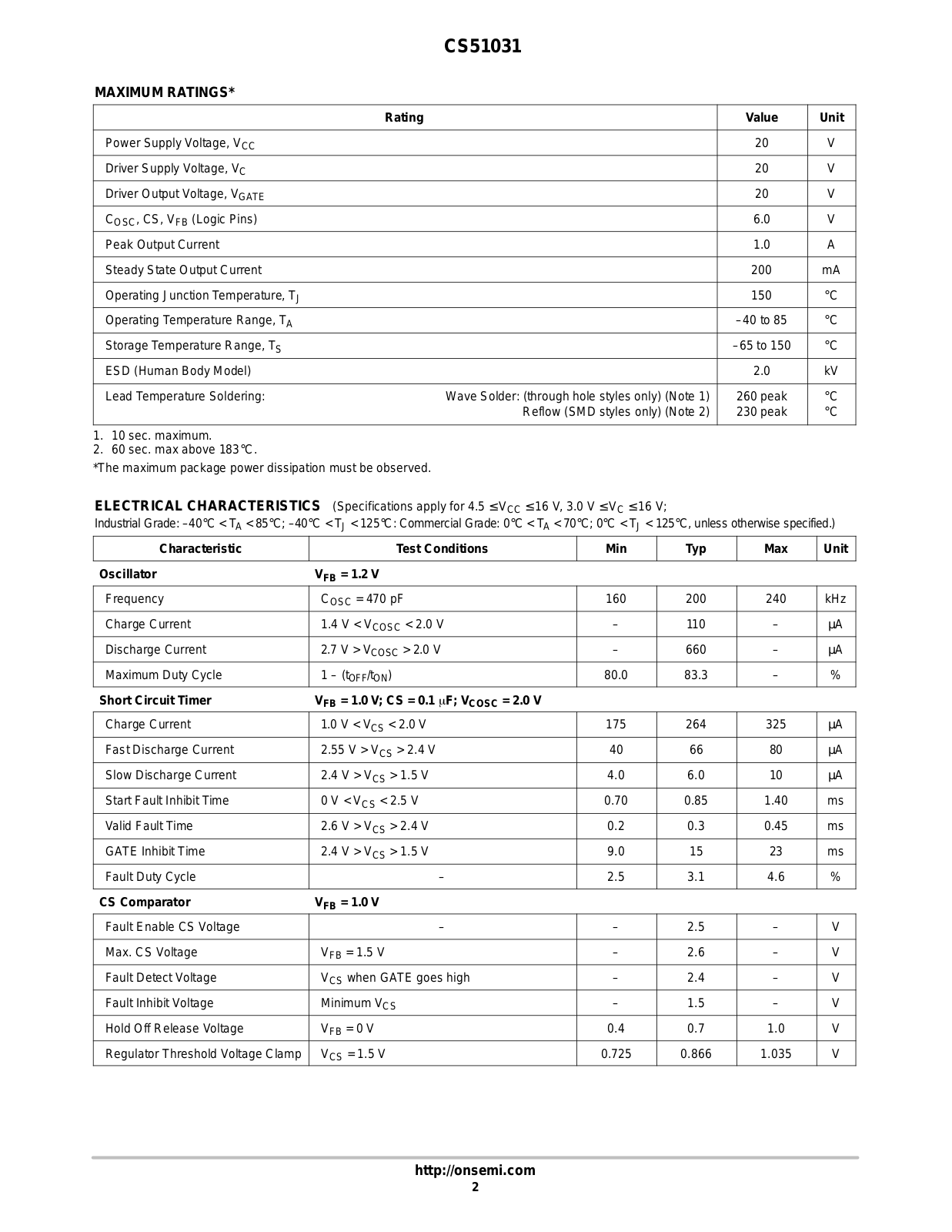
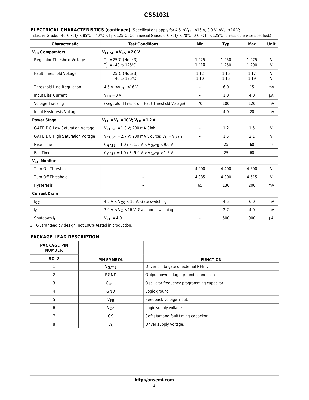
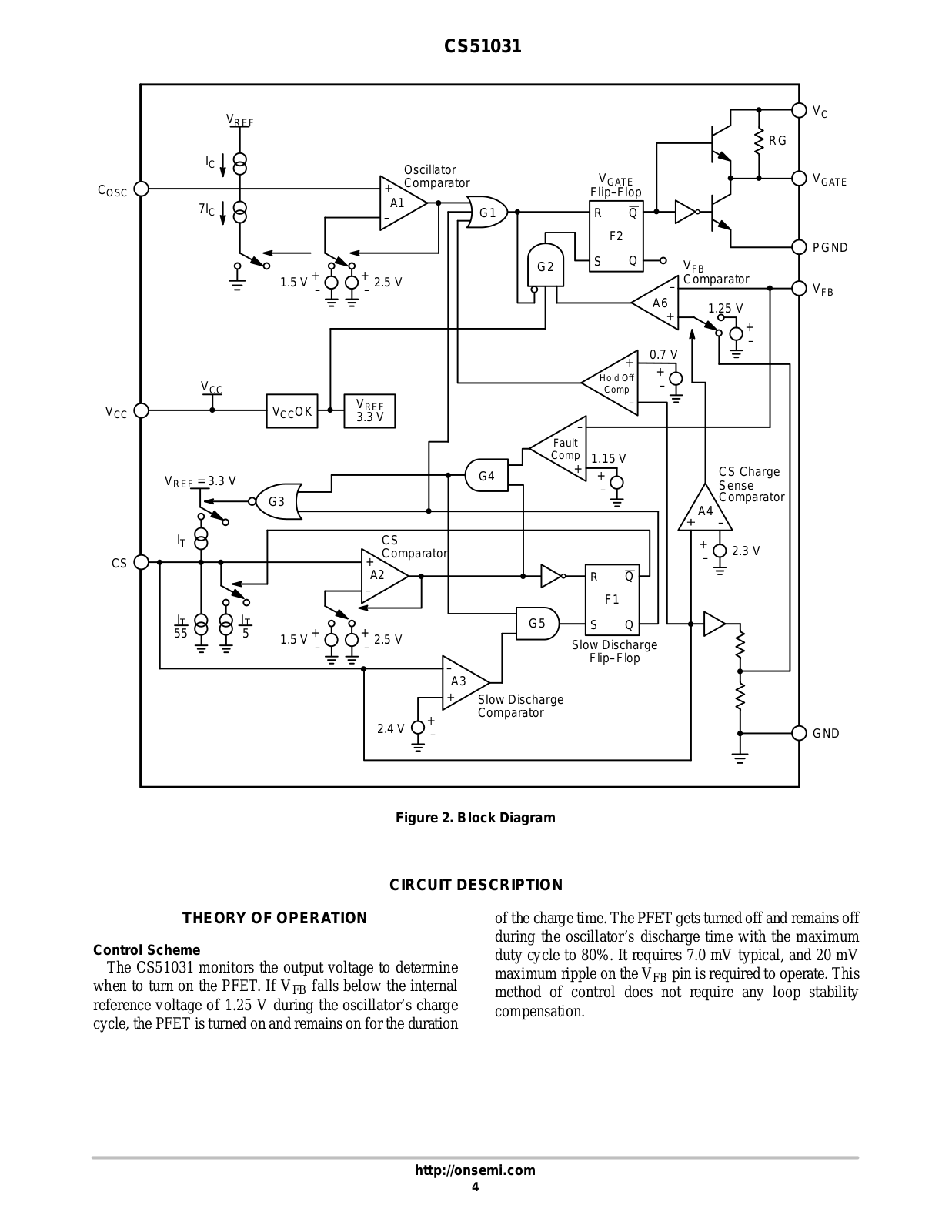
CS51031
2
CS51031YD8
CS51031YDR8
CS51031YN8
CS51033
2
CS51033YD8
CS51033YDR8
CS51033YN8
CS5106
CS5106LSW24
CS5106LSWR24
CS5111
CS5111YDWF24
CS5111YDWFR24
CS5112
CS5112EDWF24
CS5112EDWFR24
CS51220
CS51221
CS51221ED16
CS51221EDR16
CS51221EN16
CS51227
CS5124
CS5124XD8
CS5124XDR8
CS5126
2
CS5126-KL
CS5126-KP
CS5126XD8
CS5126XDR8
CS5127GDW16
CS5127GDWR16
CS51311
CS51311GD14
CS51311GDR14
CS51312
CS51312GD16
CS51312GDR16
CS51313
CS51313GD16
CS51313GDR16
CS5132
CS5132GDW24
CS5132GDWR24
CS51414
CS5150GD16
CS5150GDR16
CS5150GN16
CS5150H
Loading...
Loading...
Nothing found
CS51031
Datasheet (CHERRY Semiconductor)
8 pgs
159.82 Kb
0
Datasheet (ON Semiconductor)
12 pgs
91.88 Kb
0
Table of contents
Loading...
Datasheet CS51031 Datasheet (ON Semiconductor)
...
Datasheet Datasheet (ON Semiconductor)
Download
Specifications and Main Features
Frequently Asked Questions
User Manual
Download
Page 1
Page 2
Page 3
Page 4
Page 5
Page 6
Page 7
Page 8
Page 9
Page 10
Page 11
Page 12
Loading...
+
hidden pages
Unhide
You need points to download manuals.
1 point = 1 manual.
You can buy points or you can get point for every manual you upload.
Buy points
Upload your manuals


")