

Installation and operating instructions
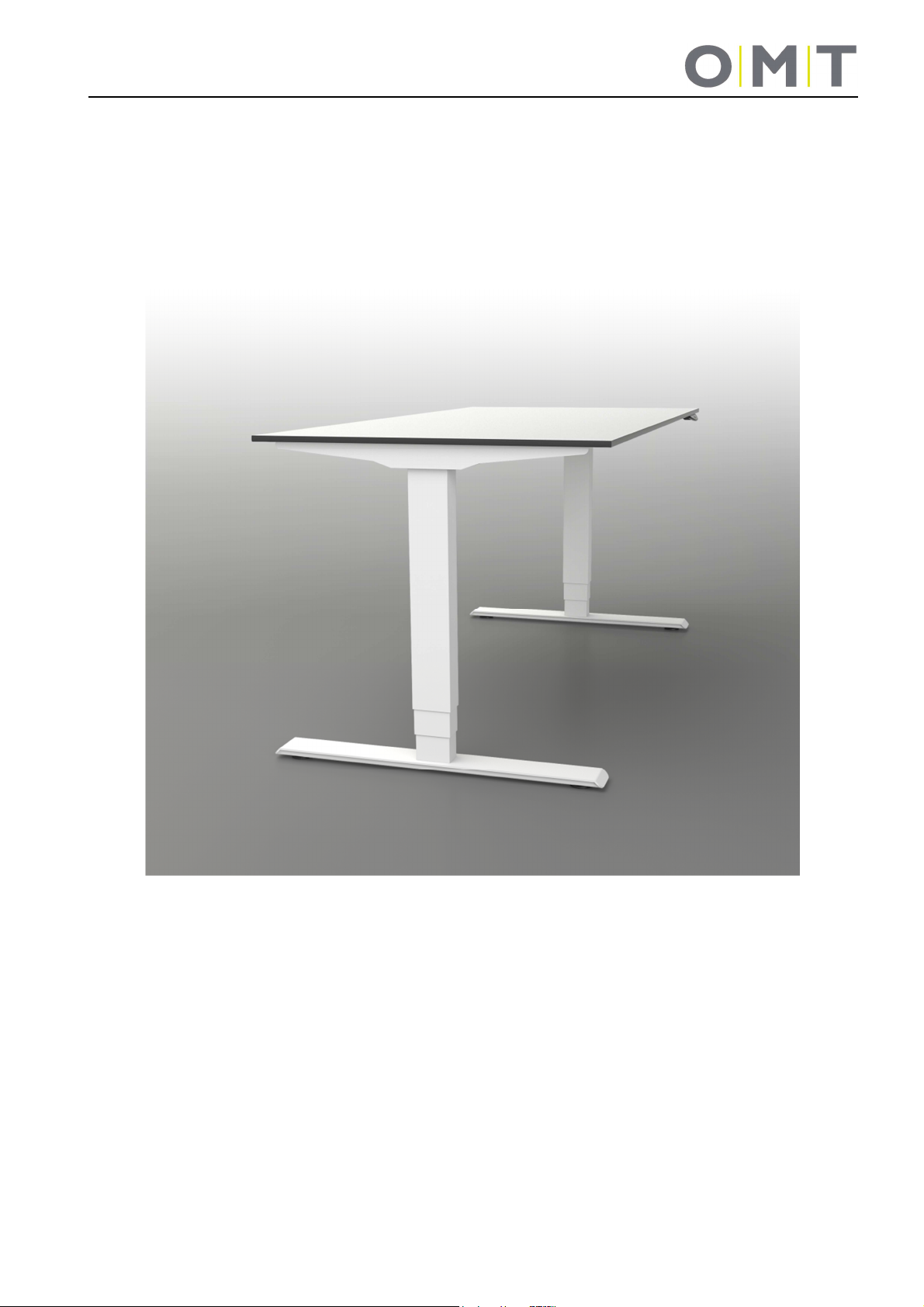
Electrically height-adjustable
sit/stand work desks
System: 9029 FreeStand
with SMART motor control
(E-components 9901 + 9902)

Table of contents
1 Preface ............................................................................................................................................................ 4
1.1 Use as intended ............................................................................................................................................. 4
1.2 Target group and previous knowledge ........................................................................................................ 4
1.3 Symbols used in the safety instructions ...................................................................................................... 5
1.4 Safety Instructions ....................................................................................................................................... 5
1.4.1 General safety instructions .................................................................................................................... 5
1.4.2 Before installation, deinstallation or troubleshooting .............................................................................. 7
1.4.3 Before initial operation .......................................................................................................................... 7
1.4.4 During operation .................................................................................................................................... 7
1.4.5 Important information for resellers ........................................................................................................ 7
1.4.6 Indication service note .......................................................................................................................... 8
1.5 Repairs ........................................................................................................................................................ 9
2 Warranty .......................................................................................................................................................... 9
3 Maintenance / Cleaning ................................................................................................................................... 9
4 Assembly ....................................................................................................................................................... 10
4.1 Installing the actuators .............................................................................................................................. 10
4.2 Assembly of the worktop support and cross-beams ................................................................................. 11
4.3 Assembly of the desktop ........................................................................................................................... 11
4.4 Assembly of the controller and hand-switch .............................................................................................. 11
4.5 Commissioning .......................................................................................................................................... 12
4.5.1 Connections to the SMART motor controller ...................................................................................... 12
4.5.2 Procedure during commissioning ........................................................................................................ 13
4.5.3 Connect the drives .............................................................................................................................. 13
4.5.4 Connect the hand-switch ..................................................................................................................... 14
4.5.5 Connect the power supply cable /mains cable .................................................................................... 14
4.6 Assembly of optional accessories ............................................................................................................. 14
5 Initialisation / Reset ....................................................................................................................................... 14
6 Control ................................................................................................................................................................ 15
6.1 Normal operation ....................................................................................................................................... 15
6.2 Operation with 9901 1810 hand-switch with display (optional) ................................................................. 16
Change the height display unit (S5 menu) .................................................................................................... 16
Calibrate the height display ........................................................................................................................... 16
6.3 Operation with 9901 19xx hand-switch with display and memory (optional) ............................................ 16
How to save a position: ................................................................................................................................. 17
How to retrieve a saved position: .................................................................................................................. 17
Change the height display unit (S5 menu) .................................................................................................... 17
Calibrate the height display ........................................................................................................................... 17
6.3.1 9901 1910 Hand-switch with display and memory (optional) ............................................................. 18
6.3.2 9901 1970 Hand-switch with display and memory (optional) ............................................................. 19
6.3.3 9901 1970 Hand-switch with display and memory (optional) ............................................................. 20
2

7 Troubleshooting ............................................................................................................................................. 21
8 Error messages in the hand-switch display (optional) ................................................................................... 22
9 Click codes of the controller .......................................................................................................................... 23
10 Technical data ............................................................................................................................................... 24
11 Tests and certificates ..................................................................................................................................... 25
12 Address ......................................................................................................................................................... 26
3

1 Preface
Dear customer,
We are pleased that you have decided to purchase our product. These instructions explain how to assemble,
use and maintain the sit/stand desk. All sit/stand desks are put through a thorough quality inspection before
leaving our factory. If you ever have any problems with our desk base, feel free to contact our service
department any time.
It is important to follow these instructions when assembling the desk base. Any changes on the desk base or an
improper usage can have an effect on the safety, functioning and service life!
These operating instructions are intended for all sit/stand desks from the 9029 FreeStand system with the
SMART motor controller but, due to different versions/types, can deviate from the illustrations.
Oelschläger Metalltechnik GmbH
1.1 Use as intended
This sit/stand desk may be used solely as an office desk in the professional sector. Changes to the desk base
are prohibited. This sit/stand desk must be assembled, put into operation and functionally checked by skilled
personnel. The use of this sit/stand desk for any purpose other than the purpose stated above is only
permissible with the consent of Oelschläger Metalltechnik.
The basic function of the desk is the electromotive height adjustment of the desktop. This function can be
performed with all hand-switches that are available from us.
1.2 Target group and previous knowledge
These operating instructions are aimed at the following group of persons:
• The commissioning staff that assembles and commissions the sit/stand desks.
• Furniture installers, maintenance staff who commission the sit/stand desk in sales rooms or at the final
customer.
The following knowledge is required to commission, assemble the FreeStand sit/stand desk:
• Mechanical and electrical basic knowledge (corresponding illustration)
• Reading the instructions
4

1.3 Symbols used in the safety instructions
Danger: These safety instructions point out an imminent danger for the life and health of persons!
Non-compliance with these warnings can result in danger to life, life-threatening injuries and
property damage.
Attention: These safety instructions point out possible dangers from electrical current!
Non-compliance with these warnings can result in injuries and property damage!
Note: These safety instructions point out important information which you must follow for the safe
operation of the FreeStand sit/stand desk.
Danger: These safety instructions point out a possible danger of crushing which exists in
exceptional cases.
Non-compliance with these warnings can result in danger to life, life-threatening injuries and
property damage.
Note: Note on the obligation to read the operating instructions!
Note: Pull the power cord before going to the next step!
1.4 Safety Instructions
These operating instructions contain safety instructions which inform you about potential hazards and thus
facilitate the safe operation of the FreeStand sit/stand desk. Please be sure you comply with these safety
instructions!
This section provides you with general safety information that does not refer to any specific work step. You can
find the job-specific safety instructions in the respective section of the operating instructions. You will find
additional safety instructions on the individual parts of the FreeStand sit/stand desk.
1.4.1 General safety instructions
Note: Before assembly/commissioning, of the FreeStand sit/stand desk, you must read and comply
with the operating instructions!
Attention: Never open the SMART motor controller under any circumstances! There is a danger of
electric shock.
Attention: The FreeStand sit/stand desk is not designed for continuous duty. The desktop height
must not be adjusted without interruption for a time period longer than the operating time stated on
the rating plate.
Attention: The SMART motor controller must only be operated with the mains voltage specified on
the rating plate!
5

Before commissioning, make sure the mains voltage on the rating plate of the motor controller
matches your mains voltage!
Danger: This unit can be used by children aged 8 years and above and by persons with reduced
physical, sensory or mental capabilities or lack of experience and knowledge when they are
supervised or instructed on the safe use of the device and understand the resulting risks.
Danger: Do not let children play with the device!
Danger: Cleaning and user maintenance must not be carried out by unsupervised children.
Attention: You must use the supplied power supply cable! Make sure that the power supply cable
is not damaged. Operating the FreeStand sit/stand desk with a damaged power supply cable is
prohibited!
Attention: You must disconnect the power supply cable from the mains supply before switching
drives, hand-switches or any other accessories on the motor controller on or off.
Attention: Use solely original FreeStand accessories from Oelschläger Metalltechnik. Use of
components and parts from third parties is prohibited!
Use of unsuitable accessories can lead to damage or the destruction of the desk base.
Attention: In case of a fault (e.g. accidental operation of the desktop such as if a button on the
hand-switch jams), please immediately pull the mains plug!
Danger: Protect the desk base and, in particular, all electrical components on the desk base from
moisture, dripping water and spray water!
Danger: There is a danger of being crushed when the desktop position is changed! For that
reason, make sure no objects and no persons are in the hazardous area and do not reach into the
hazardous area.
The optionally available corrosion protection normally detects solid objects, but there is still
continued danger of crushing for persons! The corrosion protection is a system safeguard and NOT
personal protection!
Attention: Alterations on the components of the desk base including the motor controller and
controls are prohibited!
Danger: The electromotive driven FreeStand sit/stand desk must not be operated in explosive
atmospheres!
Danger: In case of faults it is possible that the desktop moves a bit during every start-up attempt
before the safety shut-down initiates. During this process, always watch out for the possible danger
of being crushed.
6

Danger: The optionally available corrosion protection is not activated during any reset process
(Section 5). During this process, always watch out for the possible danger of being crushed.
Attention: If the product is visibly damaged, never assembly it or continue to use it!
1.4.2 Before installation, deinstallation or troubleshooting
• Stop the sit/stand desk.
Note: Switch off the power supply and pull out the power cable!
• Remove all weights from the sit/stand desk.
• Only trained electricians are permitted to open or replace electrical equipment.
• Do not operate the desk in moist rooms such as bathrooms.
• Never use the desk in explosive environments.
1.4.3 Before initial operation
• Make sure the desk is assembled in accordance with these instructions.
• Check to see if the operating voltage of the desk matches the local power supply.
(See rating plate on the controller, standard = 230V)
• Connect the plug connectors from the actuator and the side panels to the controller.
• Connect the mains cable to the controller.
1.4.4 During operation
• If the drives or the controller make any unusual noises or cause any unusual odours during operation,
interrupt the power supply.
• Make sure that the cables are not damaged.
• When operating the sit/stand desk, make sure that no objects or body parts can get trapped.
• All moving parts of the desk base must have at least 25 mm clearance to the adjoining components.
1.4.5 Important information for resellers
We consider resellers companies that purchase the FreeStand sit/stand desk from Oelschläger Metalltechnik
and that resell it as their own product after adding a table surface.
Note: For reasons of EU conformity and product safety, we recommend that the users provide their
products with operating instructions in the respective official EU language.
7
Note: Be sure to enclose operating instructions in your finished product that include all safety
instructions required by the consumer for the safe handling of your product.
Note: The operating instructions for your finished product must include the following warning: You
must read these operating instructions before you start using the product (height-adjustable
workstation).
Point out to your consumer that the operating instructions must be kept near the product (heightadjustable workstation).
Danger: It is mandatory that you put your product (height-adjustable workstation) through a risk
analysis so that you can react to any possible residual hazards (e.g. through structural measures or
warnings in the operating instructions and/or safety instructions on your product).
Note: Make sure that no unauthorised persons (small children, persons under the influence of
medication, etc.) handle your product or the FreeStand sit/stand desk.
1.4.6 Indication service note
Danger: Use solely genuine original accessories! Only skilled personnel are permitted to perform
assembly work! Otherwise you will forfeit all claims for warranty or guarantee.
Danger: In case of a fault, please promptly contact your customer service representative! Only
original FreeStand sit/stand desk spare parts are approved for repairs. Only skilled/authorised
personnel are permitted to replace them! Otherwise you will forfeit all claims for warranty or
guarantee.
8

1.5 Repairs
In case of a technical defect on this device, please contact an authorised customer service representative. You
can find solutions for simple faults in Section 7!
Attention: In the interest of preventing malfunctions, only authorised service personnel are
permitted to make any repairs.
Attention: Opening any components of this desk base produces risks for the following
malfunctions.
2 Warranty
We provide a 24-month warranty on this desk base. The warranty covers all material and production errors and
applies from the date of production (see rating plate). The warranty is only valid under the condition that the
desk base has been properly and professionally assembled and has been used within the scope of the
described parameters; that maintenance has been performed correctly and that repairs have been performed
solely by authorised service staff.
The sit/stand desk must not be improperly handled or used and no changes are permitted to be made on the
desk base; otherwise the warranty expires. Please refer to our General Terms and Conditions for additional
information.
3 Maintenance / Cleaning
Regularly remove dust and dirt from the desk base, in particular from the guide tubes, and make sure that there
are no damages and cracks.
Check all fastening screws to make sure they are securely fastened and check all plug connectors, cables and
plugs including proper functioning.
Danger: Clean the controller, actuator and the desk base only with a dry or slightly moist cloth.
Danger to life!
Attention: Aggressive cleaning agents can cause damage or discolourations on the product. Use
only agents with pH-values of 6-8.
Danger: Never let any fluids get into the system (controller, actuator, cable and base). Danger to
life!
9
Run
Installation
4 Assembly
Use only screws that correspond to the enclosed base drawing for the assembly of your desk base.
Attention: Incorrect screws can cause damage to the desk.
Danger: The power cable of the motor controller must be disconnected during assembly of the
desk base!
Attention: Before assembly and commissioning of the FreeStand sit/stand desk, make sure the
product is acclimatised for the temperature and relative humidity values stated in the technical
data!
4.1 Installing the actuators
For side elements with permanently welded actuators, proceed with Point 4.2.
Side elements with bolted actuators must be installed first on the assembly columns. Use the bolts in the
desk base drawing.
The max. tightening torque is 10 Nm!
The max. depth of engagement of the M10 bolts is 9 mm!
If you have asymmetric actuators (C-shape) you will need a left-hand and a right-hand side element.
M10 bolts as per base drawing
10

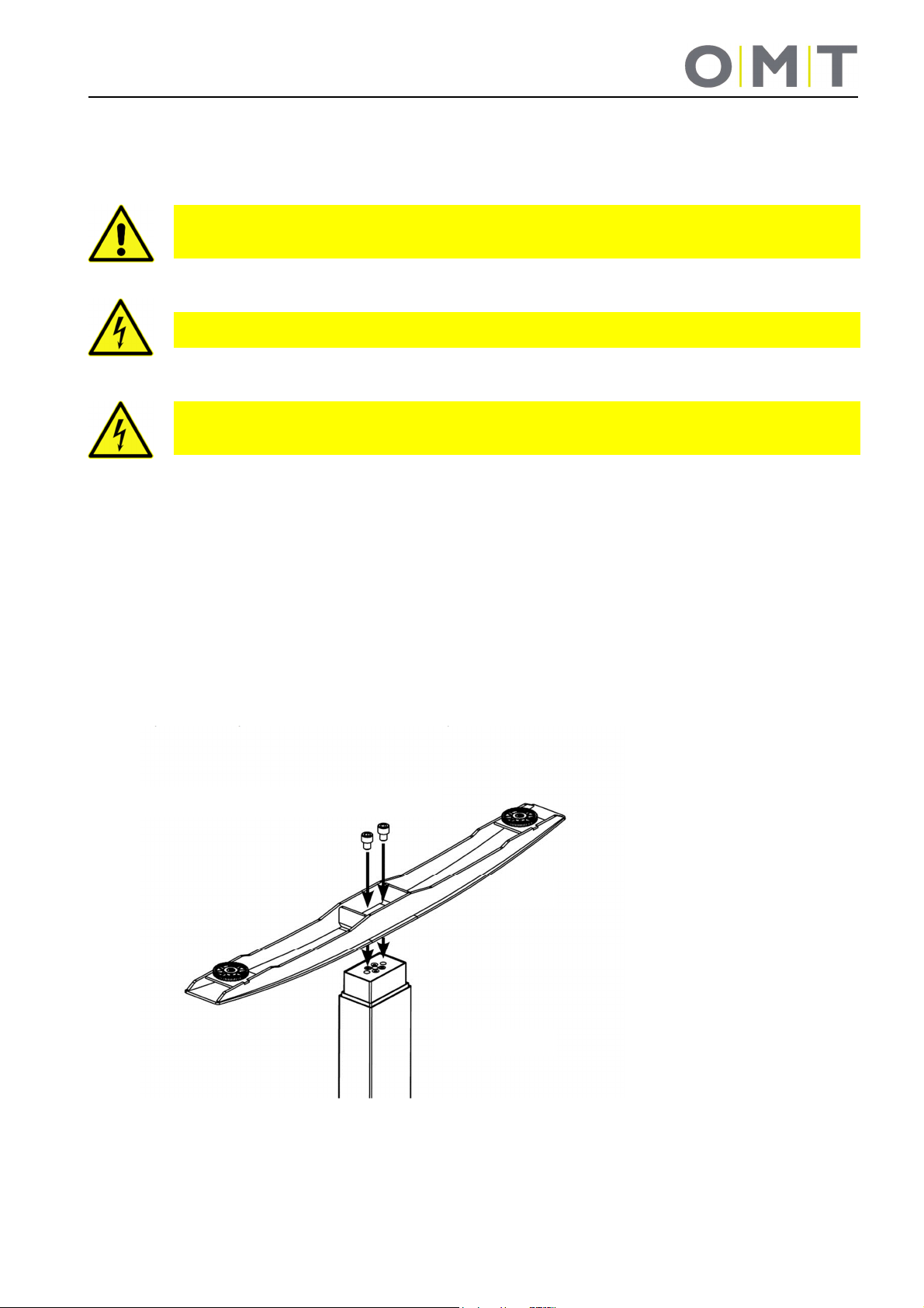
4.2 Assembly of the worktop support and cross-beams
Now assemble the two cross-beams and the support elements on both side elements. To do that, use
solely the M8 bolts as per the base drawing! The max. tightening torque for these bolts is 20 Nm.
From the inside, screw
two bolts into the crosshead threads.
4x M8 bolt
From the outside, screw two
bolts into the bracket threads
of the support elements.
Note: Experience has shown that it is better to first loosely preassemble the bolts for the crossbeams and then tighten them in the described sequence.
4.3 Assembly of the desktop
If a CPU holder
should be
integrated into the
system, then please
connect both
interior bolts to the
cross-heads via the
column's head
plate.
Now fasten the desktop to the desk base in accordance with the base drawing. To accomplish that, 6.5
mm holes are provided on the desk frame; they are suitable for ø5.5 to ø6.0 mm bolts. Use all provided
bolting points.
*1)
4.4 Assembly of the controller and hand-switch
Now attach the controller and the hand-switch to the desktop. ø5.4 mm are provided on the controller
and ø4.5 mm holes are provide on the hand-switch for that purpose. For the controller, use bolts with a
11

raised or cylindrical head. The tightening torque depends on the desktop material, but should not exceed
*1)
2 Nm.
*1)
The screws are not included in the scope of delivery since they have to be selected depending on the
material and the thickness of the desktop.
4.5 Commissioning
Commissioning includes all jobs that are necessary for electrical height adjustment of the FreeStand
sit/stand desk with the aid of the SMART motor controller. The prerequisites for commissioning are:
• The desk base has been completely assembled as per 4.1 – 4.3
• The SMART motor controller and the hand-switch are assembled (as explained in Section 4.4)
Danger: Only expert/authorised personnel are allowed to commission the motor controller!
Expert/Authorised personnel have completed the required electrotechnical apprenticeship and are
familiar with these operating instructions.
Attention: Before assembly and commissioning of the FreeStand sit/stand desk, make sure the
product is acclimatised for the temperature and relative humidity values stated in the technical
data!
4.5.1 Connections to the SMART motor controller
12

4.5.2 Procedure during commissioning
Attention: Plug in the power supply cable/mains cable only after all other electrical connections
have been made! (All motors, the hand-switch and possibly additional accessories are connected
to the controller.)
To commission the FreeStand sit/stand desk, proceed as follows:
4.5.3 Connect the drives
Make sure that the connection cables of the drives reach from both sides up to the corresponding
controller connection. For extremely long desks, it might be necessary to assemble the controller offcentre. For especially large desks, if necessary use an extension cable for the connection cable of the
drives.
Connect the drives of the side panels and the controller using the motor cable. The plug connectors on
the 8-pin motor sockets must firmly latch! For controllers with more connections for drives than the
number of drives available, you must start by connecting the (M1) connection. If, for example, only a
drive is connected to the motor controller, the M2 connection remains open.
Note: When inserting the motor cable, the sequence of M1, M2 must be maintained!
13

4.5.4 Connect the hand-switch
Connect the hand-switch to the 7-pin hand-switch socket (HS)
of the controller.
Note: You can choose from a large number of hand-switches that fit the SMART motor controller!
Please ask Oelschläger Metalltechnik for information on the available types!
4.5.5 Connect the power supply cable /mains cable
Attention: Before you plug in the power supply cable, check again
• to see if the mains voltage matches the rating plate of your controller.
• to see if all components are plugged into the correct sockets.
The SMART motor controller is ready for operation as soon as the power supply cable is plugged
in!
Note: Initialisation of the desk base is required the first time the power supply cable is connected
(RESET). This is described in Section 5.
Attention: Use only the supplied mains cable! It is mandatory to provide the SMART motor
controller with a 3-pin mains cable with protective earth.
Attention: Fasten all cables to the desk base or the desktop so they cannot get damaged during
operation.
4.6 Assembly of optional accessories
If you have also ordered an optional cable tray, plug it onto both cross-beams as the last step. Do not
let any cable get jammed in. Route the mains cable left or right out of the cable tray on the side element.
On certain desk versions, assembly of the cable tray is only possible in the upper position of the desk
base. To do that, you must first initialise the desk base!
5 Initialisation / Reset
After assembling or if the desk has been disconnected from the power supply for a long time, malfunctions on
the desk are possible. The same applies if the connection between the drives and the controller was separated.
In these cases, the desk controller has to be initialised.
If the controller expects a reinitialisation, the downward movement of the desk is only possible at reduced
speed. For hand-switch versions with a display, this is indicated in addition by the “Reset LED”. It turns off as
soon as initialisation has been successfully concluded.
14

To initialise, move the desk to the bottom position; to do that, press the down key on the hand-switch until all
drives have reached the lowest position. Press the down key once again and keep it pressed (approx. 5
seconds) until the desk moves slightly down and then back up. Let go of the button only after the desk stops
moving. If you let go of the button too soon, that causes a malfunction on the desk. If this happens by mistake,
you have to repeat the process.
Attention: The top limit stop of the controller is preset. For this reason, use only controllers that
were supplied as suitable for the respective desk base.
Danger: The optionally available corrosion protection is not activated during any reset process.
During this process, always watch out for the possible danger of being crushed.
6 Control
6.1 Normal operation
Use the "up" and "down" buttons to move the desk up or down in the direction of the arrow. The desk stops
when it reaches the limit positions. Keep the button pressed until the desired position has been reached.
9901 1900 Hand-switch 9901 1800 Hand-switch (optional)
9901 1950 Hand-switch (BASIC), optional
(with all hand-switch variants)
9901 1960 Hand-switch (BASIC), optional Milling picture for installation of the hand-switch in a
desktop
15

6.2 Operation with 9901 1810 hand-switch with display (optional)
This hand-switch is additionally equipped with a display for indication of the current desk height in centimetres
or inches.
The reset LED indicates that initialisation is required (see initialisation section). It stays illuminated until the
initialisation is concluded.
The info LED indicates that the controller has detected a fault. Simultaneously the display shows the “Exx” error
code instead of the current desk height. To repair the error, see the troubleshooting section.
If you stop pressing the hand-switch after a while, the display turns off if no important operating condition is
being displayed. As soon as you press a button, the display switches back on.
Change the height display unit (S5 menu)
The height display of the hand-switch can be shown in either centimetres or inches. Use the S5 menu to convert
the unit. If the display was set to centimetres, after menu selection the height will be shown in inches; if inches
were previously displayed, you can revert to the centimetre display.
To change the unit proceed as below:
1. Press the menu button (approx. 3-5 sec.) until the display shows “S x”.
(x stands for a number; if “S 5” is being displayed, continue with 3.)
2. Press the UP or DOWN button until the display shows “S 5”.
3. Press the S-button. The display is now reset to the previous setting from centimetres to inches or from
inches to centimetres.
To exit the menu, wait about 10 seconds until the height display reappears.
Calibrate the height display
If the displayed height does not match the actual height you can correct the display as below:
1. Press the S-button and let it go again.
2. Press the DOWN button until the height display starts flashing. (approx. 5 sec.)
3. Measure the desk height and enter the measured value (depending on the setting, in centimetres or inches)
using the UP or DOWN button. Confirm the input by briefly pressing the S-button.
To exit the menu, wait about 10 seconds until the height display reappears.
6.3 Operation with 9901 19xx hand-switch with display and memory (optional)
All hand-switches with display and memory always have the same mode of functioning; possible differences are
described in the section on the individual hand-switch.
16

The display shows the current desk height in centimetres or inches and on top of that it shows the operating
condition of the controller along with any detected problems with the error code “Exx”. You can find a list of all
possible error codes in the troubleshooting section.
If you stop pressing the hand-switch after a while, the display turns off if no important operating condition is
being displayed. As soon as you press a button, the display switches back on.
The “Up” and “Down” buttons plus the “Move desk up” and “Move desk down” buttons move the desk as
described in 6.1.
Note: If the hand-switch type on the motor controller is replaced, this has to be done in an
unpowered state (pull the mains plug beforehand). Only then will the new type be correctly
detected by the motor controller.
How to save a position:
Move the desk to the desired height with the “Up” or “Down” buttons.
Press the “S” button (“S” appears in the display) and then one of the position buttons 1 to 2 or 4 (you can see,
e.g. “S 1” in the display). The controller confirms the storage procedure with a double-click sound and after
approx. 2 seconds the current desk height is shown in the display. This way you can save 2 or 4 different
positions.
How to retrieve a saved position:
Keep the desired memory setting pressed (1, 2, 3 or 4). The desk independently moves from the current
position to the saved position. The button has to be pressed until the position is reached; if you let go
beforehand, the desk stops moving.
Change the height display unit (S5 menu)
The height display of the hand-switch can be shown in either centimetres or inches. Use the S5 menu to convert
the unit. If the display was set to centimetres, after menu selection the height will be shown in inches; if inches
were previously displayed, you can revert to the centimetre display.
To change the unit proceed as below:
1. Simultaneously press the buttons “1”, “2” and “UP” (approx. 3-5 sec.) until the display shows “S x”. (x stands
for a number; if “S 5” is being displayed, continue with 3.)
2. Press the UP or DOWN button until the display shows “S 5”.
3. Press the S-button. The display is now reset to the previous setting from centimetres to inches or from
inches to centimetres.
To exit the menu, wait about 10 seconds until the height display reappears.
Calibrate the height display
If the displayed height does not match the actual height,
you can correct the display as below:
1. Press the S-button and let it go again.
2. Press the DOWN button until the height display starts flashing. (approx. 5 sec.)
3. Measure the desk height and enter the measured value (depending on the setting, in centimetres or inches)
using the UP or DOWN button. Confirm the input by briefly pressing the S-button.
17

To exit the menu, wait about 10 seconds until the height display reappears.
6.3.1 9901 1910 Hand-switch with display and memory (optional)
This hand-switch is equipped with a display to indicate the current desk height in centimetres or inches. In
addition, it is possible to save 4 “Memory” positions (desk heights).
The reset LED indicates that initialisation is required (see initialisation section). It stays illuminated until the
initialisation is concluded.
The info LED indicates that the controller has detected a fault. Simultaneously the display shows the “Exx” error
code instead of the current desk height. To repair the error, see the troubleshooting section.
The LED’s “Container, Flex, Ergotrainer and Pin” are reserved for optional functions and are not used in
standard systems.
The Up (2) and Down (2) buttons work like the up and down buttons in the standard version
18

6.3.2 9901 1970 Hand-switch with display and memory (optional)
with TOUCH functioning for undertable assembly
This hand-switch has a drawer push function and is equipped with a display to indicate the current desk height
in centimetres or inches. In addition, it is possible to save 4 “Memory” positions (desk heights). A button lock is
integrated to protect against accidental operation.
Note: Use all 4 provided screws with a cylinder, round or flat head with a max. head diameter
of 10 mm and a max. thread diameter of 5 mm for the assembly of this hand-switch.
Note: For the assembly, use all provided attachment points. Do NOT overtighten the
assembly screws. The hole clearances must match the assembly holes. Otherwise the housing
could distort and lead to malfunctions of the push function. The correct tightening torque depends
on the type of screw being used and on the desktop material.
Activating and deactivating the display/button lock
The button in the display indicates an activated button lock.
You can activate and deactivate the button lock by swiping left or right under the display.
Note: The swiping direction is irrelevant.
Note: Make sure you only swipe lightly over the display without pressing any buttons!
19

Note: The display must be active (e.g. show the current height) when you activate/deactivate
the button lock. Briefly press a button, e.g. the UP button, to activate the display if applicable.
6.3.3 9901 1970 Hand-switch with display and memory (optional)
with TOUCH function for installation in the desktop
This hand-switch is for installation in a desktop from the top and is equipped with a display to indicate the
current desk height in centimetres or inches. In addition, it is possible to save 2 “Memory” positions (desk
heights). A button lock is integrated to protect against accidental operation.
Milling picture for installation of the hand-switch in a desktop
Activating and deactivating the display/button lock
The button in the display indicates an activated button lock.
You can activate and deactivate the button lock by swiping left or right
under the display.
20

Note: The swiping direction is irrelevant.
Note: Make sure you only swipe lightly over the display without pressing any buttons!
Note: The display must be active (e.g. show the current height) when you activate/deactivate
the button lock. Briefly press a button, e.g. the UP button, to activate the display if applicable.
7 Troubleshooting
Fault Cause Repair
Desk does not move No power supply Plug in mains cable; if applicable, check the plug connector
on the controller
Desk only lowers
slowly
Desk only moves
slowly
Desk only moves
briefly on one side
and then remains
stationary
No connection or loose
connection to the
drives/side panels
No connection to the
hand-switch
Max. lifting force
exceeded
Max. operating time
exceeded
Drive defective Please contact Customer Service
Controller defective Please contact Customer Service
Actuator defective Replace actuator
Controller expects a
reinitialisation
Max. lifting force
exceeded
No connection or loose
connection to the
drives/side panels
Drive defective Please contact Customer Service
Check, if applicable fix plug connector connection from the
motor cable to the controller and the drives.
Check, plug-in plug connector to the controller
Reduce weight
The controller will independently reactivate after approx. 3
minutes
ATTENTION!
The max. travel time of 2 minutes is only available after an
idle time of at least 18 minutes.
See page 11
Reduce weight
Check, if applicable fix plug connector connection from the
motor cable to the controller and the drives.
21
8 Error messages in the hand-switch display (optional)
Display Cause Repair
HOT The controller monitors
the operating time (timecontrolled) and its max.
temperature value was
exceeded.
E00 M1 – Internal error Pull the mains plug!
E01 M2 – Internal error
E02 M3 – Internal error
E12 M1 – Defective
E13 M2 – Defective
E24
E25 M2 – Overcurrent
E36 M1 – Not connected The motor is not connected
E37 M2 – Not connected
M1 – Overcurrent
Wait until the controller has cooled off and the “HOT” display has
disappeared. The desk is then operational again.
ATTENTION!
The operating time is calculated only as long as the mains voltage is
applied. If the controller is disconnected from the mains, the most
recent value in the controller is saved!
and contact the your customer service representative!
Pull the mains plug!
Repair the external short-circuit, check the cable to the monitors for
possible damages
or
Plug in the involved socket of the correct motor.
Put the controller back into operation.
Collision? -> if applicable, repair
Max. load exceeded -> take the load off the desk.
If the error persists, please contact customer service.
Check the cable/plug connection to the motors and do a reset
E48 Overcurrent
Motor group 1
E55 Motor group 1 –
Synchronisation lost
E60 Collision detected Optional ISP and sensor function
E61 Motor replaced Connection to the motor was interrupted or a new motor was
E62 Overcurrent Controller – total overcurrent, overload
E63 External sensor or cable
not connected
E64 Authentication error Reinitialise desk (RESET)
E65 Overcurrent or
short-circuit
E67 Overvoltage Pull the mains plug!
E70 Change the
drive configuration
(Motor = Drive in the installation column or in the side panel)
Collision? -> if applicable, repair
Max. load exceeded -> take the load off the desk.
Motor positions too different
If applicable, reduce the load on the desk
Reinitialise the desk (RESET)
Remove cause
connected
Reinitialise desk (RESET)
External crushing protection strip or special add-on module not
connected; if applicable check plug connector
If error occurs during drive.
Collision? Load too heavy?
and contact the your customer service representative!
Mains or power pack fluctuations?
Pull the mains plug and wait at least 5 seconds. Then reinitialise the
desk (RESET)
22

Normal operation:
Emergency mode:
Last shut
-
down incomplete / forced reset:
Display Cause Repair
E71 Sensor – configuration
changed
E81 Internal error Reinitialise desk (RESET)
Note: The PowerFail detection of the motor controller detects power failures and saves all
relevant data before the voltage drops below a critical level.
In a few exceptional cases, this saving process is not possible, and during the next controller startup, E81 is displayed and the controller clicks three times.
To repair this error, a manual reset is required (see Section 5).
Note: If there is a power failure during the height adjustment or if the mains cable is pulled, a
manual reset might be necessary.
If the error cannot be repaired as described above, pull the mains plug, wait for several minutes and try to
reinitialise the desk!
If the error continues to occur, unplug the desk from the mains and contact customer service.
This error list is suitable for firmware 1.9.14 and higher!
An (optionally) mounted sensor was removed or the connection has
been lost.
Comply with the separate instructions for the sensor!
Pull the power supply cable and reconnect after several seconds.
If the error occurs regularly, unplug the power supply cable and
contact customer service.
9 Click codes of the controller
As soon as the motor controller is supplied with power, the controller uses the integrated relay to acoustically
inform the user about the system status and the reason for the most recent shut-down.
Number
of clicks
2x When
1x
3x – 6x
When Status information
The system is functioning without problems
mains on
The system is running in emergency mode; the drives cannot be used. Check the
LED if applicable and/or the error code on the display of the hand-switch.
Check the LED if applicable and/or the error code on the display of the handswitch.
23
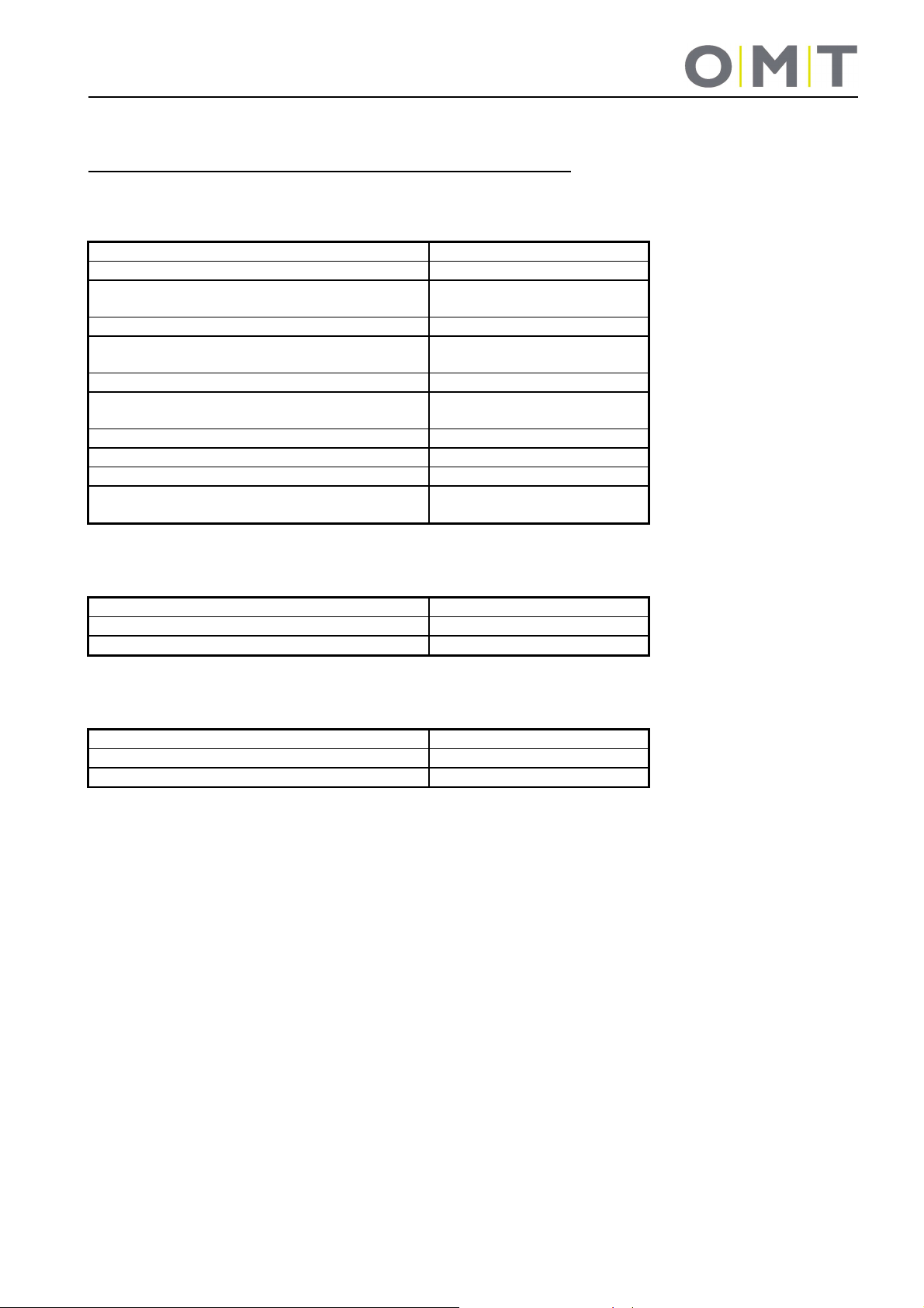
10 Technical data
System: 9029 FreeStand with SMART motor controller
General
Individual drive (installation column or side panel, support foot) with SMART-e-2
Desk base with 2 drives (installation column or side panels) with SMART-e-2
Operating voltage 207-253 V / 50-60 Hz
Nominal voltage 220-230 V / 50-60 Hz
Standby power at nominal voltage,
primary (typical)
Ambient temperature during operation 0-30°C
Permissible relative humidity
(for operation)
Storage and transport temperature -40°C to +85°C
Permissible relative humidity
(for storage)
Protection class I
IP Class IP 20
Max. operating time 10% (2 min. on / 18 min. off)
Nominal lift speed of the drive columns
(reduced under max. load)
Lifting capacity max. 600 N (≈ 60 kg)
Lift length depending on version See drawing
Current consumption max., primary 216 W
Lifting capacity max. 750 N (≈ 75 kg)
Lift length depending on version See drawing
Current consumption max., primary 216 W
≤0.3 W
5-85% (non-condensing)
5-90% (non-condensing)
38 mm/s
24

3089061
11 Tests and certificates
The drive system has been tested in accordance with the following standards:
Electromagnetic compatibility (EMC Standard 2004/108/EEC)
EN 61000-6-2:2005 Electromagnetic compatibility (EMC)
EN 61000-6-3:2007 Electromagnetic compatibility (EMC)
EN 61000-3-2:2006 Electromagnetic compatibility (EMC)
EN 61000-3-3:2008 Electromagnetic compatibility (EMC)
Low Voltage Directive (Low Voltage Directive 2006/95/EC)
EN 62233:2008 Measurement methods for electromagnetic fields of household appliances and similar
apparatus with regard to human exposure
EN 60335-1:2012 Household and similar electrical appliances
Internal and similar uses
Safety-related parts of control systems
EN ISO 13849-1:2008 Safety of Machinery
Safety-related parts of control systems
Performance Level „b“
25

12 Address
Oelschläger Metalltechnik GmbH
Hertzstraße 1-3
27318 Hoya - Germany
Tel.: +49 (0) 4251 - 816 - 0
Fax: +49 (0) 4251 - 816 - 81
E-mail: info@oelschlaeger.de
Internet: www.oelschlaeger.de
Company Headquarters: Hoya
District Court – HRB 31030
Managing Director: Andreas Spreen
9029_Bedienungsanleitung_SMART_E9901_Rev1.doc - Version: 07/07/2015 - MR
26
 Loading...