

OMS Antriebstechnik omsHypodrive EC 2-25 Installation Instructions Manual
OMS Antriebstechnik
Bahnhofstraße 12
36219 Cornberg
Germany
Telephone: +49 (0) 5650 / 969-0
Telefax: +49 (0) 5650 / 969-100
Translation from german original!
Installation instructions
according to Annex VI of the EC Directive 2006/42/EC Mechanical Equipment
and further product details
Escalator Machine
Model:
oms
Hypodrive EC 2 - 25
Coupling Machine ; Duplex Machine ; Dual Machine
Please archive this document for future reference
OMS No. Date of Manufacture
Month / Year

Installation instructions EC 2 - 25
Coupling Machine, Duplex Machine , Dual Machine
(Technical changes reserved – Last Changes 10/2018)
Page 2 of 89

Installation instructions EC 2 - 25
Coupling Machine, Duplex Machine , Dual Machine
(Technical changes reserved – Last Changes 10/2018)
Page 3 of 89
List of Contents
Page
1 INTRODUCTION 5
2 SAFETY INSTRUCTIONS FOR OMS ESCALATOR MACHINES 6
2.1 Applicable Use 6
2.2 Non Applicable Use 7
2.3 Warranty and Liability for the Escalator Drive 8
2.4 Dangers, that are associated with the Escalator Drive 9
2.5 Instructions for Safe Use 9
2.6 Requirements and Qualification - Installation and Maintenance Personnel 9
2.7 General Information 9
3 INSTALLATION 10
3.1 Assembly 10
4 CONSTRUCTION AND FUNCTION 19
4.1 Technical Data 22
4.2 Noise Emission Information 22
4.3 Manufacturers Identification Plate 22
4.4 Modules and Additional Parts 24
4.5 Alternative equipment 24
4.6 Spare parts 25
5 TRANSPORT AND STORAGE 26
5.1 Transport 26
5.2 Lifting the machine 27
5.3 Storage 30
6 REGULAR USE AND MAINTENANCE 32
6.1 Recommended Routine Maintenance 32
6.2 Error – Troubleshooting Errors 33
6.3 Gearbox Oil 33
6.4 Brake Maintenance 37
6.5 Replacing the motor 48
6.6 Replacing the elastic coupling ring 48
6.7 Adjusting the braking function sensor 49
6.8 Adjusting the break lining wear control 50
6.9 Adjustment of Non Reversal Device (NRD) and Speed Sensor 51
6.10 Mounting of chain Wheel / flange of intermediate coupling 52
6.11 Dismounting of chain wheel / flange of intermediate coupling 53
7 DISASSEMBLY 54
7.1 Disassembly of the Escalator Drive 54

Installation instructions EC 2 - 25
Coupling Machine, Duplex Machine , Dual Machine
(Technical changes reserved – Last Changes 10/2018)
Page 4 of 89
7.2 Scrapping the Escalator Drive 54
8 ADDENDUM 55
A OMS technical data – escalator machine EC 2 - 25 56
B OMS dimensioned drawing – escalator machine EC 2 - 25 58
C Electrical connections 63
D Pin assignment – Wieland connector 66
E TÜV Certificate Brake mechanism for escalator drive unit 67
F EC-safety data sheet Klübersynth GH 6-220 68
Installation instructions EC 2 - 25
Coupling Machine, Duplex Machine , Dual Machine
(Technical changes reserved – Last Changes 10/2018)
Page 5 of 89
1 Introduction
These instructions include pictograms for commenting on Warnings and Safety Issues.
Application Tip:
Additional Comments and
Information, no danger involved
Warning:
of a general risk for the machine or a
human safety hazard
Warning:
of dangerous currents, a liability of
serious damage to health or death
Warning:
of hot surfaces, a liability of serious
damage to health and / or serious material
damage
Warning:
of crush injuries, a liability of serious
damage to health
Warning:
of drawing in, a liability of serious
damage to health
Warning:
DANGER
Risk for the machine or a human safety hazard,
a liability of serious damage to health or death

Installation instructions EC 2 - 25
Coupling Machine, Duplex Machine , Dual Machine
(Technical changes reserved – Last Changes 10/2018)
Page 6 of 89
2 Safety Instructions for OMS Escalator Machines
2.1 Applicable Use
The OMS – escalator traction machine EC 2 - 25 is solely intended for usage in escalators and
passenger conveyors (travelators, moving walks) for public transportation according to EN 115
and DIN EN ISO 12100 part 1 + 2.
The installation and use of the EC 2-25 for other purposes is not applicable. The OMS ANTRIEBSTECHNIK is not liable for personal injury and or damage resulting from none applicable usage.
All Planning, installations and maintenance work may only be carried out by qualified personnel.
Qualified personnel are such who having studied for qualifications, or are experienced, or have
received instruction and have the knowledge relating to the relevant standards and directives,
safety regulations and local knowledge required to install and maintain the machine and be able
to recognise and access the risks appertaining to this machine. (Qualified Personnel, as defined
in IEC 364).
This OMS – escalator drive is applicable to the 9th Directive of the Machine and Product Safety
Law
(9. Verordnung zum Geräte- und Produktsicherheitsgesetz [Maschinenverordnung])
and the
2006/42/EC Machine Directive. It is part of a machine, namely an escalator or a travelator and is
therefore not liable for CE certification.
The commencement of regular use is not permitted until the traction machine has been correctly installed into the escalator or travelator and the manufacturer has applied the CE label to the
escalator or travelator to certify that the safety requirements have been fulfilled for the complete product / machine as supplied by the manufacturer.
All other required regulations and certificates (e.g. applicable to general use, maintenance and
inspections) remain in force.
The drive manufacturer only respects the warranty for operation and safety of the drive if it is
has been erected, maintained and operated according to the printed specifications supplied individually with each drive. The warranty is void if the parameters outlined in the operating,
maintenance and control documentation have been exceeded. An incorrect installation or incorrect use of the system, and or violation of the standards outlined above, lead to a complete and
absolute none liability of the drive manufacturer.
The used motors are generally suitable for frequency inverter operation, provided the slew rate
limit of the motors is adhered to. Customer supplied frequency converters must be set up according to their instruction sheets, in order to comply with the requirements of the OMSEscalator Machine, and with the national EMI directives.
The escalator traction machine is only intended for installation and usage in an enclosed area.

Installation instructions EC 2 - 25
Coupling Machine, Duplex Machine , Dual Machine
(Technical changes reserved – Last Changes 10/2018)
Page 7 of 89
OMS Drives may only be stored, erected and run in dry closed areas. The IQ/OQ representative
and the user must ensure that adequate measures are taken to avoid a contamination with
building dust and or dirt.
Stopping of a running traction machine is via frequency inverter control or via the machine
brake. In emergency situations braking may be via an external, auxiliary brake on the escalator
main shaft. Make sure that when braking with such an auxiliary brake only, the traction machine is not dynamically overloaded. When braking with an auxiliary brake, this should preferably be engaged together with the machine brake.
OMS-Escalator machines may only be operated when in technically good condition and within
the parameters as described by OMS.
Applicable use also includes the following:
• Working according to the supplied instructions,
• Observing the regulatory safety and environmental requirements,
• Adherence and observance of the Escalator documentation and regulations.
2.2 Non Applicable Use
OMS Drives may not be operated in potentially explosive or environmentally aggressive areas.
Further operation is not permissible once the pre determined wear points have been achieved.
Permissible Limits:
• max. Motor Speed: refer to technical documentation;
• Local ambient temperature during operating min.: 0° C max. 45° C and 55° C for 1h.; with mo-
tor heating from -10°C up to 45°C, with additional gear box heating from (for intermediate
gear box too)-35°C up to 45°C
• Local ambient temperature without operating: -20°C max. 60°C
• The technical data and specifications on the Motor Data Label are only valid for an installation
height up to h ≤ 1000m over NN.
• Max. rel. Humidity: 85% at 20°C (none condensing).
• Operation under extreme climatic conditions must be clarified with OMS.
None applicable use also includes the following:
-
Dry operation without oil or use of a lubricant other than specified
-
Opening the Gearbox when installed on the drive
Installation instructions EC 2 - 25
Coupling Machine, Duplex Machine , Dual Machine
(Technical changes reserved – Last Changes 10/2018)
Page 8 of 89
Important:
• All work related to; Transport, Electrical Connections, pre-Service Checks and
Maintenance of the Drive System must be carried out by qualified technicians.
Incompetent work can lead to serious personal injury and / or damage.
Warning !
Special Notes appertaining to EC 2 - 25:
• The machine is very efficient and has a very low natural friction rate. The ma-
chine operates immediately after the brake has been released.
• At initial start-up, the motor must accelerate to normal speed and be run for
min. 30 seconds, before a lower standby speed can be used! This is mandatory
to warrant lubrication of the upper Hypoid bearing via the integral oil pump.
2.3 Warranty and Liability for the Escalator Drive
• The drive manufacturer only respects the warranty for operation and safety of the drive if it is
has been erected, maintained and operated according to the printed specifications supplied
individually with each drive.
• The warranty is void if the parameters outlined in the operating, maintenance and control
documentation have been exceeded.
• The customer is responsible for the qualified installation of the drive by certified personal.
• If damage or other problems are found on the Escalator or the drive, then the system must be
disabled, otherwise the operator will be liable for all damage and injury appertaining thereto.
• An incorrect installation or incorrect use of the system, particularly with respect to the forbid-
den procedures outlined above, lead to a complete and absolute none liability of the drive
manufacturer.
• This is also applicable, when after damage has occurred, the operator and/or the installer and
/or the maintenance company cannot supply a fully documented list of procedures relating to
the erection, testing, maintenance and SOP’s of the escalator.

Installation instructions EC 2 - 25
Coupling Machine, Duplex Machine , Dual Machine
(Technical changes reserved – Last Changes 10/2018)
Page 9 of 89
2.4 Dangers, that are associated with the Escalator Drive
Our escalator drives are at the cutting edge of technology and are delivered in a safe operating
configuration. Any changes made by that customer or his operative that may affect the inherent
safety of the escalator drive are not permissible
2.5 Instructions for Safe Use
If changes are observed during the service life of the machine, e.g. wear, ageing etc. then the
machine should be serviced and the changes dealt with, according to this OMS Operating Manual.
The gearbox may only be opened by OMS at our factory site; the warranty will otherwise become invalid.
2.6 Requirements and Qualification - Installation and Maintenance Personnel
All installations, maintenance work and repairs on the electrical parts of the machine may only
be carried out by qualified personnel.
Qualified personnel are such who having studied for qualifications, or are experienced, or have
received instruction and have the knowledge relating to the relevant standards and directives,
safety regulations and local knowledge required to install and maintain the machine and to be
able to recognise and assess the risks appertaining this machine. (Qualified Personnel, as defined
in IEC 364).
OMS recommend that the technical personnel acquaint themselves with the machine before it is
erected and taken into service. Please read the General- and Maintenance Instructions carefully,
these instructions will aid you to find mistakes and technical deficiencies during the installation
and operating life of the machine.
2.7 General Information
Should damage occur during transport, or should the machine appear during erection to have
errors or be damaged, please contact OMS and inform us of the damage or error.
In case of damage caused by water, please contact OMS.
A decision as to whether the damage or error can be rectified on site or not, can first be taken
after the customer has contacted OMS. OMS will then decide if the machine can be taken into
service or whether the machine should be returned - with the original packaging – to OMS.
Please retain the original packaging until after the machine has been taken into service.
Installation instructions EC 2 - 25
Coupling Machine, Duplex Machine , Dual Machine
(Technical changes reserved – Last Changes 10/2018)
Page 10 of 89
3 Installation
3.1 Assembly
Prior to installation, the intended frame or foundation upon which the escalator machines are to
be installed must always have been calculated and proved adequate.
The frame must be rigid enough to withstand all and any bending and torsional forces that may
occur during operation.
Fix the machine in the position as in the order using the four mounting holes in the gear unit
base. Using the through-holes in the support frame and bolts and nuts to ensure secure attachment is recommended.
Bolts:
M 20 quality 12.9
Torque:
550 Nm
Max. allowed uneveness of the surface : 0,05mm
If necessary, use shimps to achieve the requires eveness.
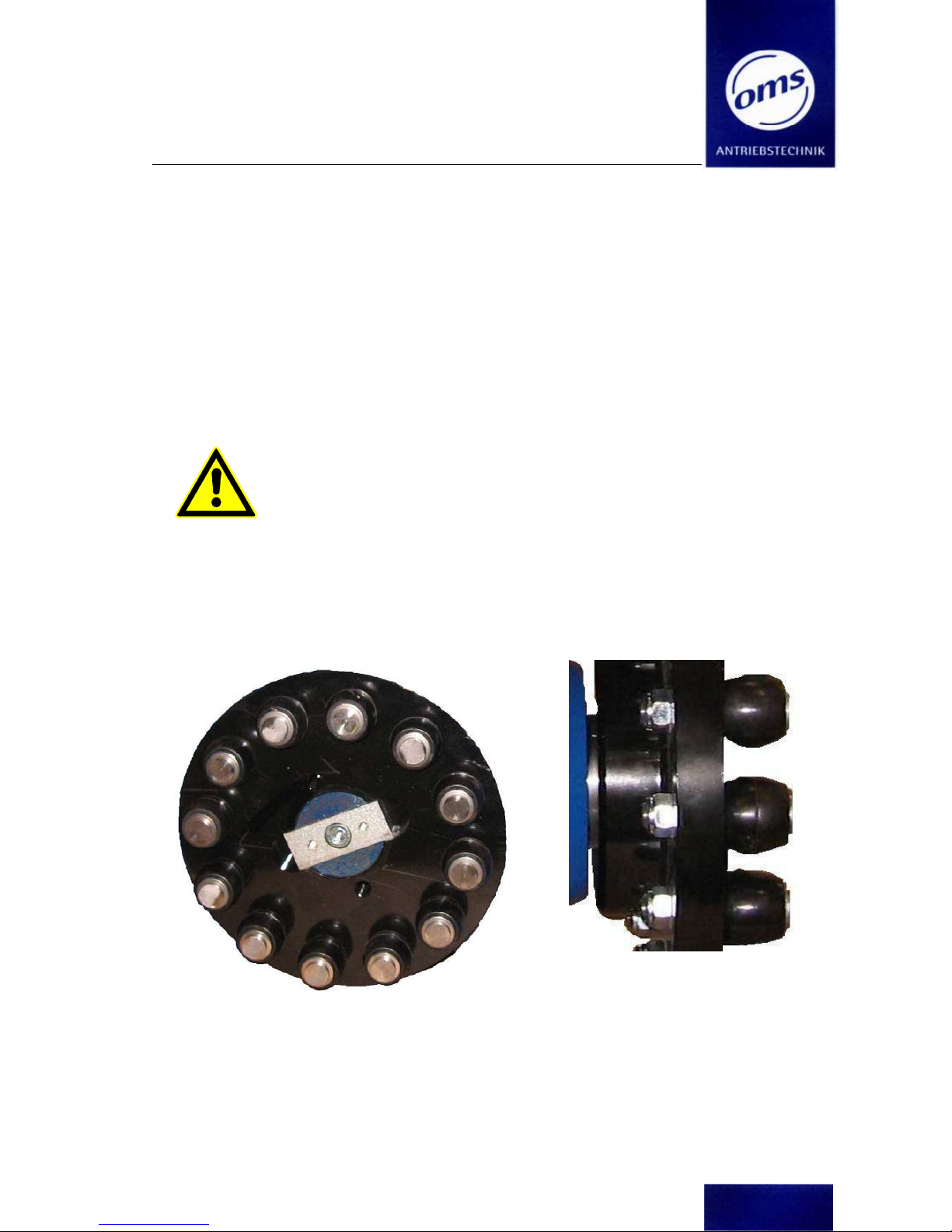
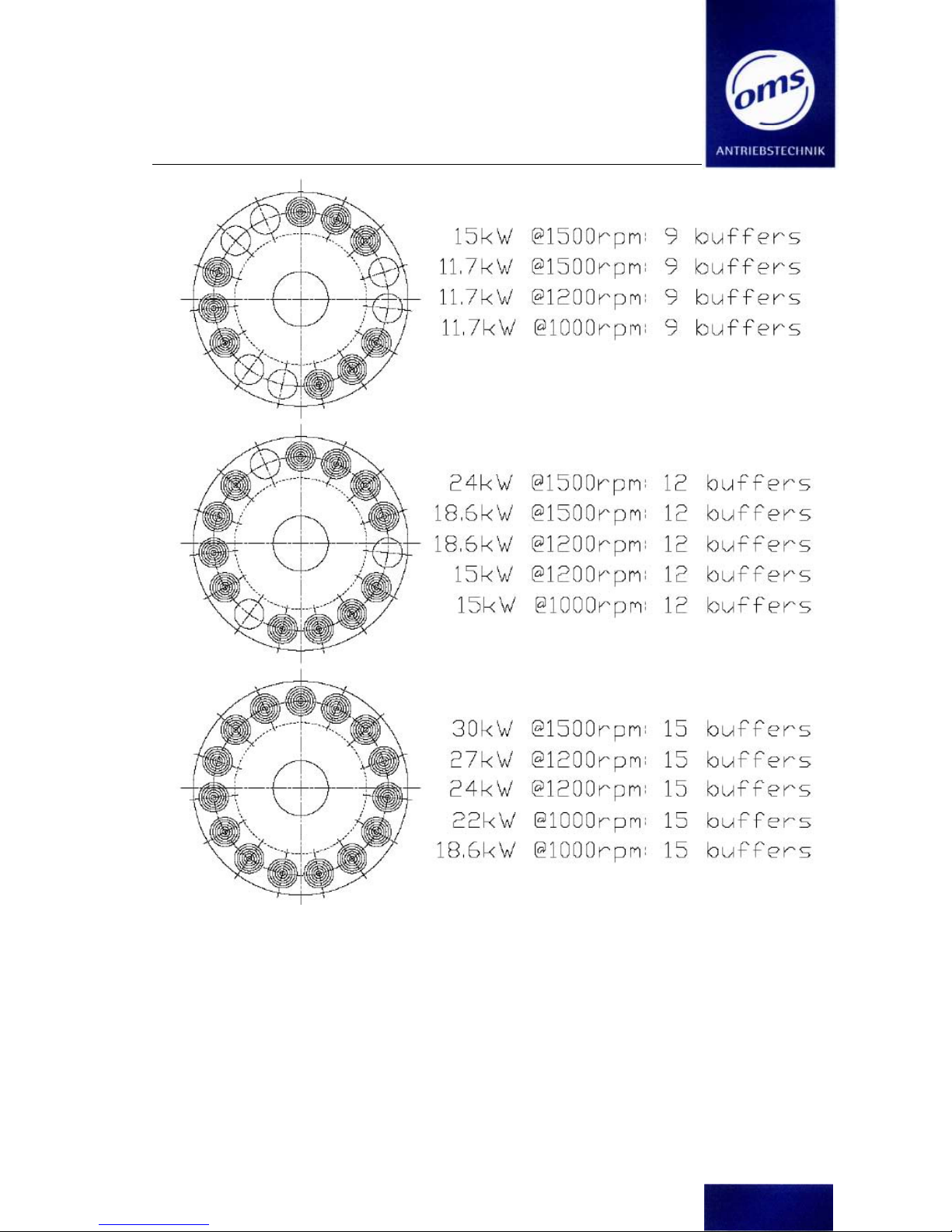
3.1.1 Assembling the intermediate coupling
The number of bolts in the coupling flange is according to the motor power..
Fig. 1a
Front view : coupling flange
with bolts
Fig. 1b
Side view
Tighten the nuts of the bolts with 120Nm!
The mounting positions of the bolts according to the motor power is shown in the following graphic :
Installation instructions EC 2 - 25
Coupling Machine, Duplex Machine , Dual Machine
(Technical changes reserved – Last Changes 10/2018)
Page 11 of 89
Installation instructions EC 2 - 25
Coupling Machine, Duplex Machine , Dual Machine
(Technical changes reserved – Last Changes 10/2018)
Page 12 of 89
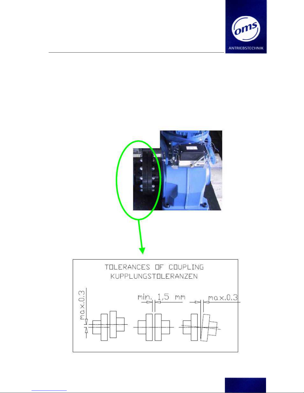
3.1.2 Adjusting the Drive unit to the Intermediate gear
Put some grease on the inner toothing of the intermediate gear outputshaft before you mount it
onto the escalator shaft.
We recommend : Klüber - Unimoly HTC Metallic.
When mounting the gear boxes take care that they will have no tensions to each other or in themselves. .
For the alignment of the two coupling flanges note the following :
Fig. 2
Installation instructions EC 2 - 25
Coupling Machine, Duplex Machine , Dual Machine
(Technical changes reserved – Last Changes 10/2018)
Page 13 of 89
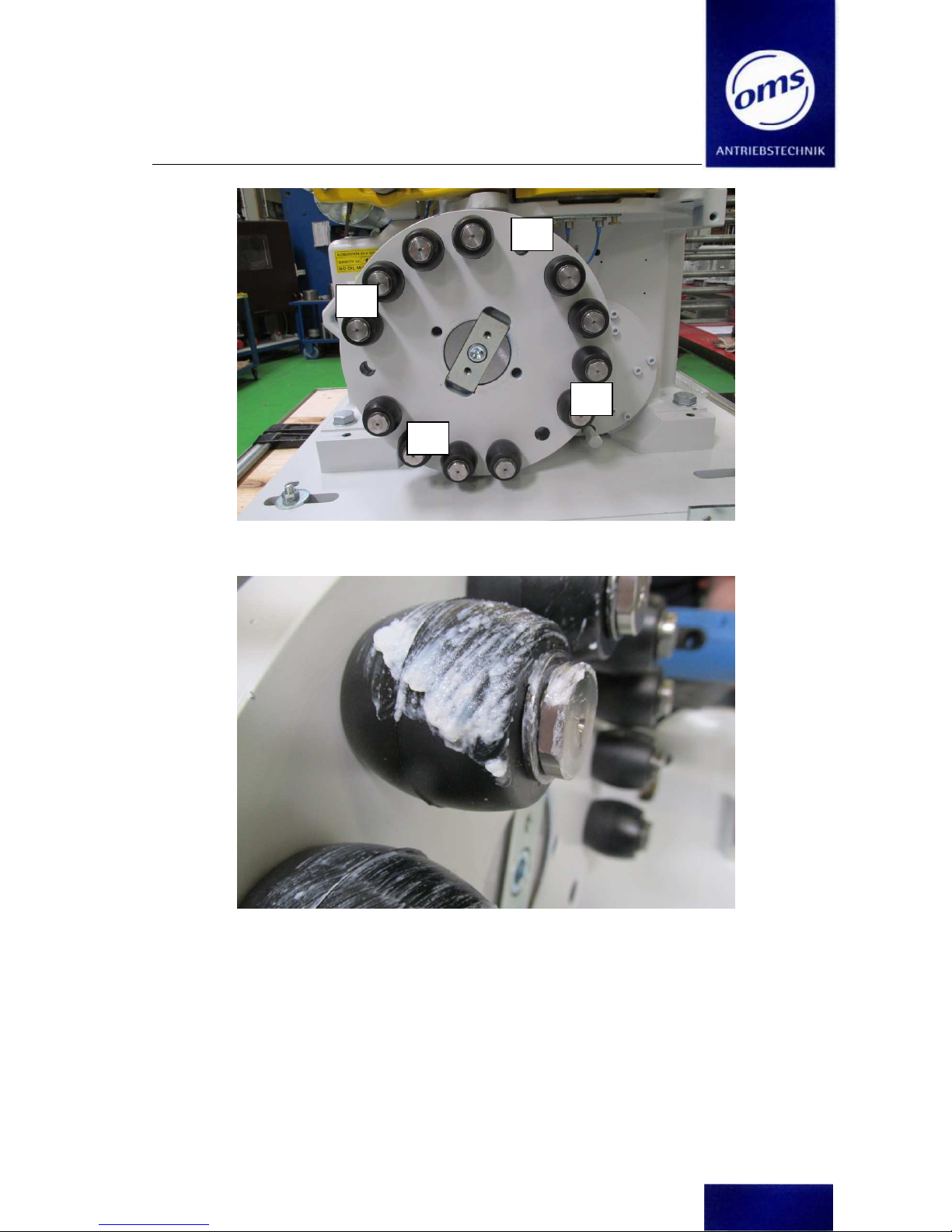
Measurement – and control points 1-4; incremental angle 90°
Before assembling the coupling put some assembling grease onto the bolts
1
2
3
4
Installation instructions EC 2 - 25
Coupling Machine, Duplex Machine , Dual Machine
(Technical changes reserved – Last Changes 10/2018)
Page 14 of 89
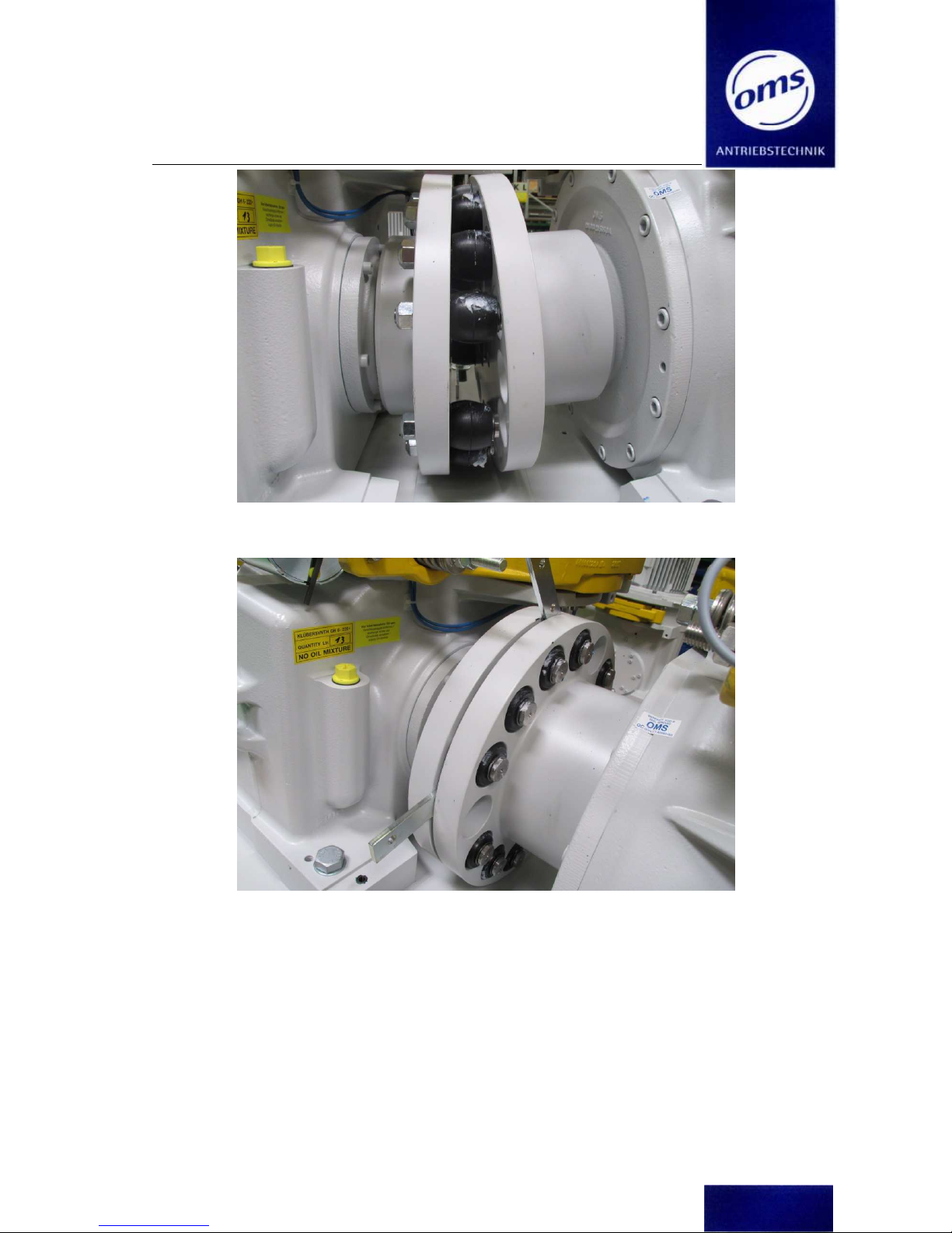
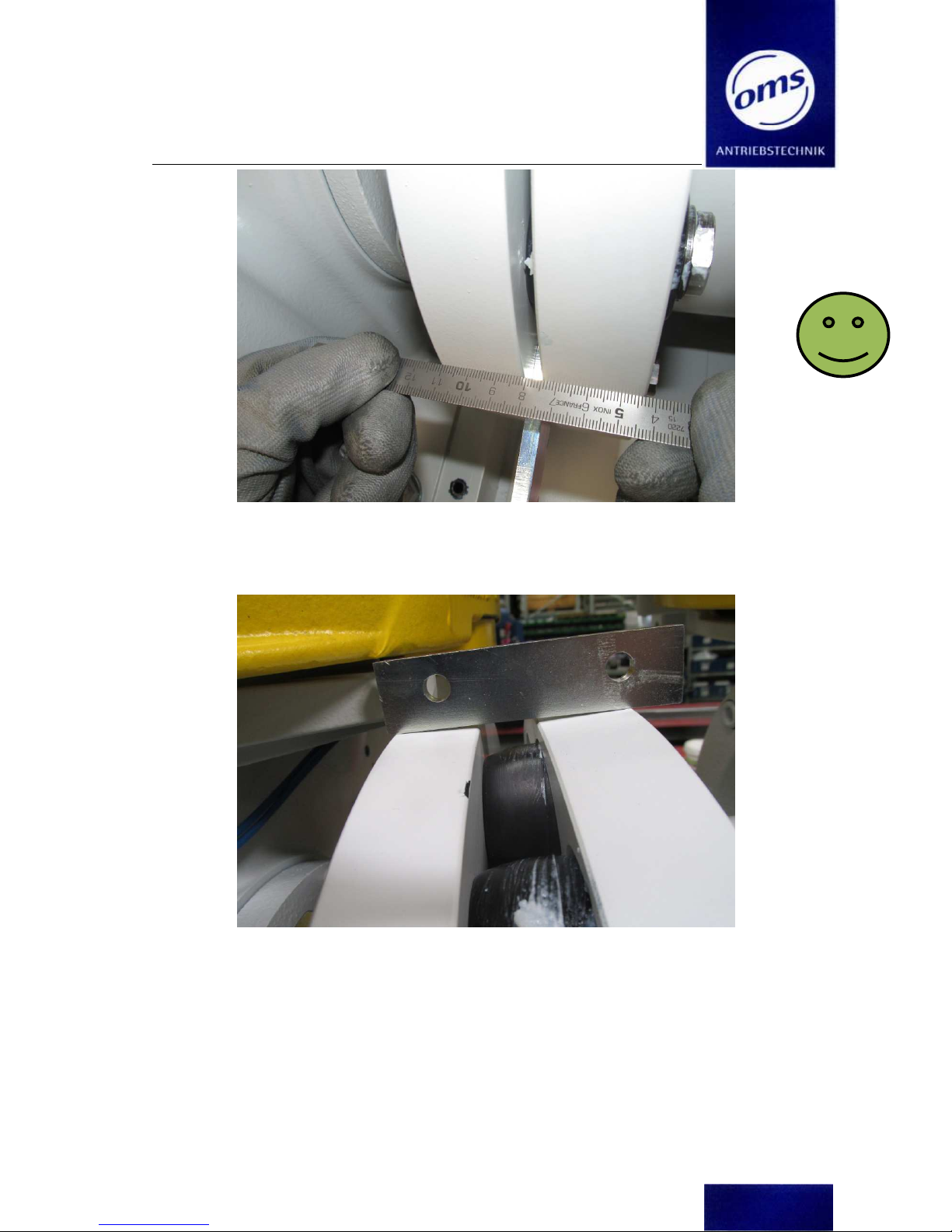
Move the bolts of the first coupling flange into the holes of the second coupling flange
To adjust the distance between the coupling flanges (min. 1,5mm – max. 6mm) it will be helpful to put
some distance gauges between the coupling flanges at the points 1-4
Installation instructions EC 2 - 25
Coupling Machine, Duplex Machine , Dual Machine
(Technical changes reserved – Last Changes 10/2018)
Page 15 of 89
After assembling the coupling the following dimensions must be proofed at the points 1-4:
Parallelism, axial alignment and angular alignment of the coupling flanges
If necessary readjust it
Angular alignment must be smaller then 0,1° or 0,3mm
Installation instructions EC 2 - 25
Coupling Machine, Duplex Machine , Dual Machine
(Technical changes reserved – Last Changes 10/2018)
Page 16 of 89
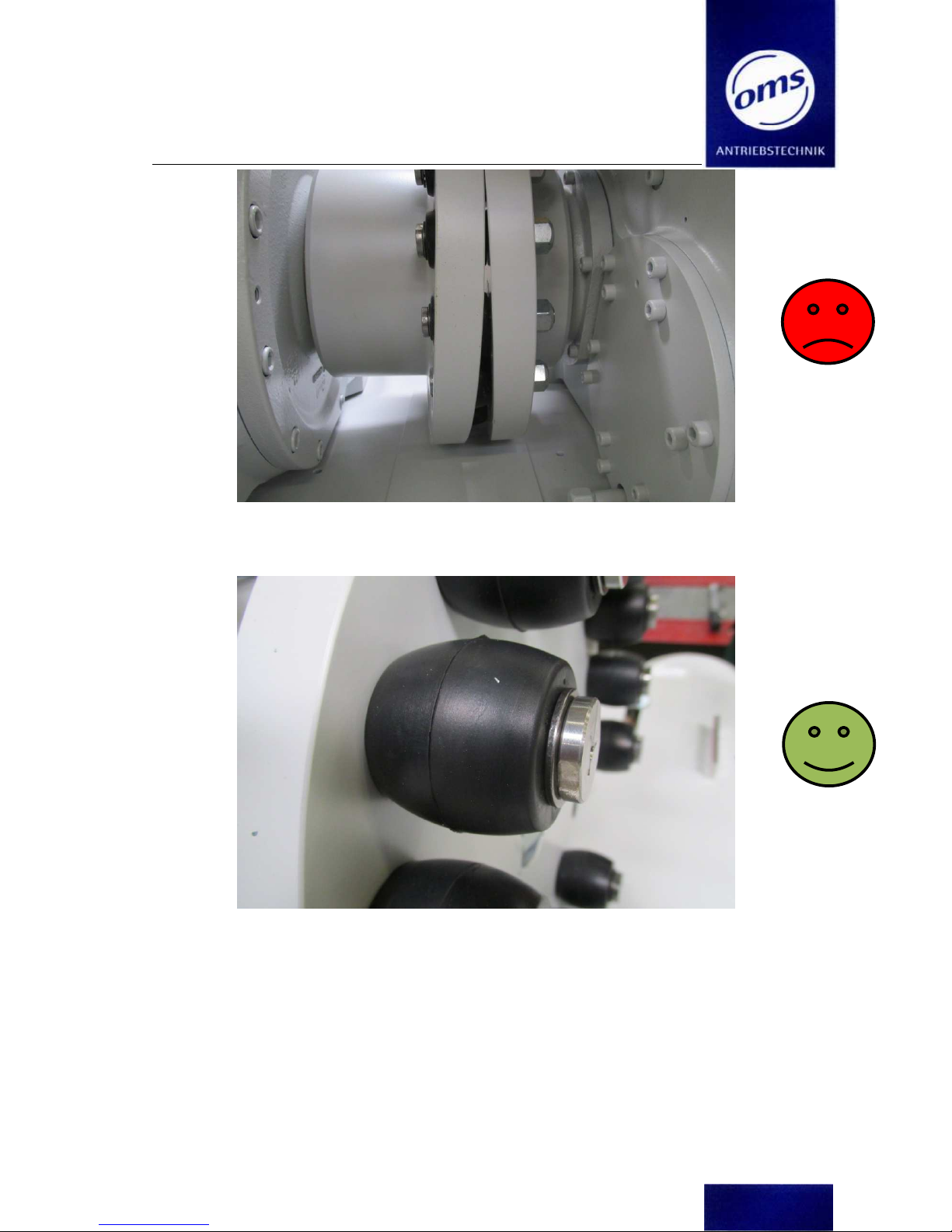
Wrong assembling: assembled like this the gear box will become an oil leak and the rubbers of the
bolts will be destroyed soon
Check the rubbers of the bolts every year. Is one rubber destroyed all rubbers must be exchanged, but
latest after 5 years in use.
Installation instructions EC 2 - 25
Coupling Machine, Duplex Machine , Dual Machine
(Technical changes reserved – Last Changes 10/2018)
Page 17 of 89
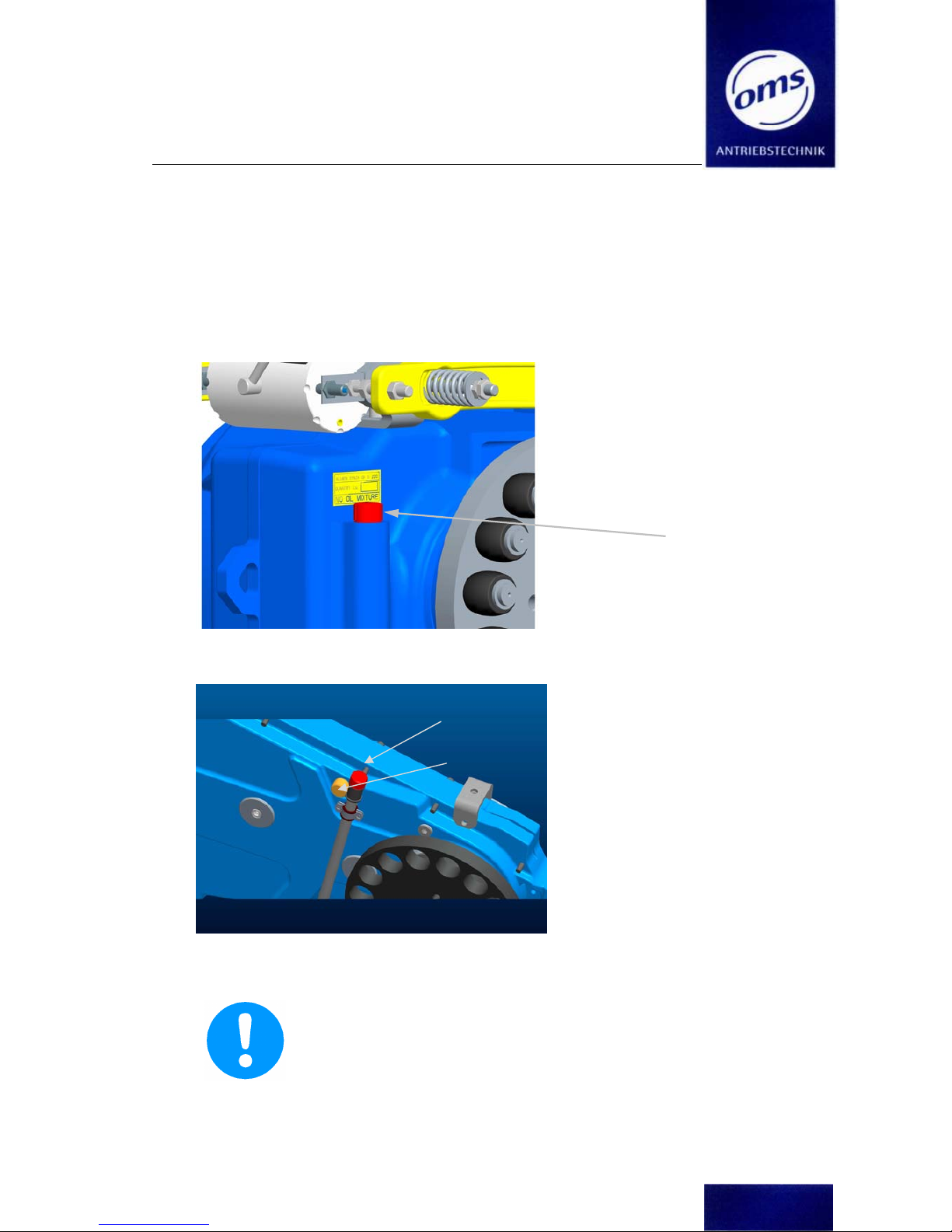
3.1.3 Assembly and installation of complete traction machine
Before commissioning:
Exchange the labelled sealing plug on the Gearbox Casing with the supplied Oil Dipstick or the
supplied Air Bleeder Valve. Take care to observe the correct positioning of the Gearbox. Retain
the sealing plug for possible future transportation of the Machine.
Fig. 3a
Fig. 3b Oil dipstick and air ventilation screw for intermediate gear
Annotation:
The Gearbox has been sealed against oil leakage during transport. The Gearbox is airtight due to the sealing plug(s). If the Gearbox were to be taken
into use with the sealing plug(s) in place, then excess pressure may build up
in the Gearbox, eventually causing the Gearbox to leak – oil will be pressed
out through the Shaft Gaskets.
The Oil Dipstick does not seal the gear box.
Electrical Connections
Screw plug
Oil dipstick
Air ventilation
screw
Installation instructions EC 2 - 25
Coupling Machine, Duplex Machine , Dual Machine
(Technical changes reserved – Last Changes 10/2018)
Page 18 of 89
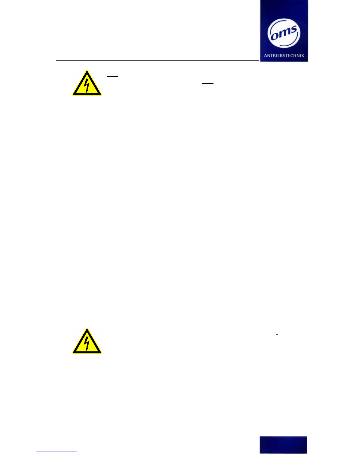
Only qualified personnel may open the Terminal Box on the Motor
and connect
the machine to the electrical supply. Only qualified personnel may carry out
repairs and service work on the electrical parts of the machine.
Disconnect the main switch beforehand and secure the switch
against unintended operation!
When you finish the work in the terminal box you have to close it! Before applying power and unscrewing the switch again. Always use isolated tools!
Important:
The electrical system for the machine has been designed according to: EN 60 204-1.
Procedure:
1. Motor:
The electrical connections should be connected as per the diagram in the Motor Terminal Box.
(See also: Appendix, Electrical Connections). Should a different wiring exit position be required,
the Terminal Box can be turned by loosening the internal fixing screws and repositioning the
Terminal Box. Fasten the terminal box and tighten the inner screws with torque of 20 Nm.
Please take care when adjusting the fine wiring of the temperature monitor switches..
2. Brake Solenoid:
The brake solenoid (Two Circuit Double Stroke Expanding Magnet) must be connected according
to the various requirements (see connection of the brake magnet to the power supply in the Appendix). Supply voltage generally 230V AC (± 10% max.)
a) for a single circuit brake (O-21 or O-31) both left and right solenoid circuits are controlled
by one module.
b) for a double circuit brake both sides of the solenoid (O-22 or O-32) are controlled by an in-
dividual module. For earthquake unsafe regions the electrical connection of the two modules is made individually, too (O-23 or O-33).
Attention! Special note appertaining to Dual - and Duplex machine: The motors
and the brake solenoids must be connected in a way if one solenoid will fail out
both motors are to stop!
Installation instructions EC 2 - 25
Coupling Machine, Duplex Machine , Dual Machine
(Technical changes reserved – Last Changes 10/2018)
Page 19 of 89
4 Construction and Function
The OMS escalator machine is a high capability traction machine, compromised of several subunits for different tasks.
Due to the high efficiency ratio of approx. 96% the machine generates little excess heat, this
ensures that the modules and aggregate parts and electronics are not exposed to excessive temperatures and therefore a detrimental effect – ageing and wear – on these parts due to temperature influence is kept to a minimum.
The oil shelf life – dependant on usage and environment – usually reaches 30.000h or more.
For average ambient temperatures of approx. 30°C and under continuous operating methods the
oil can be used for up to 30,000 operating hours. In addition to the usual checks every 2 years
the lubrication properties of the oil should be checked for (see chapter 6).
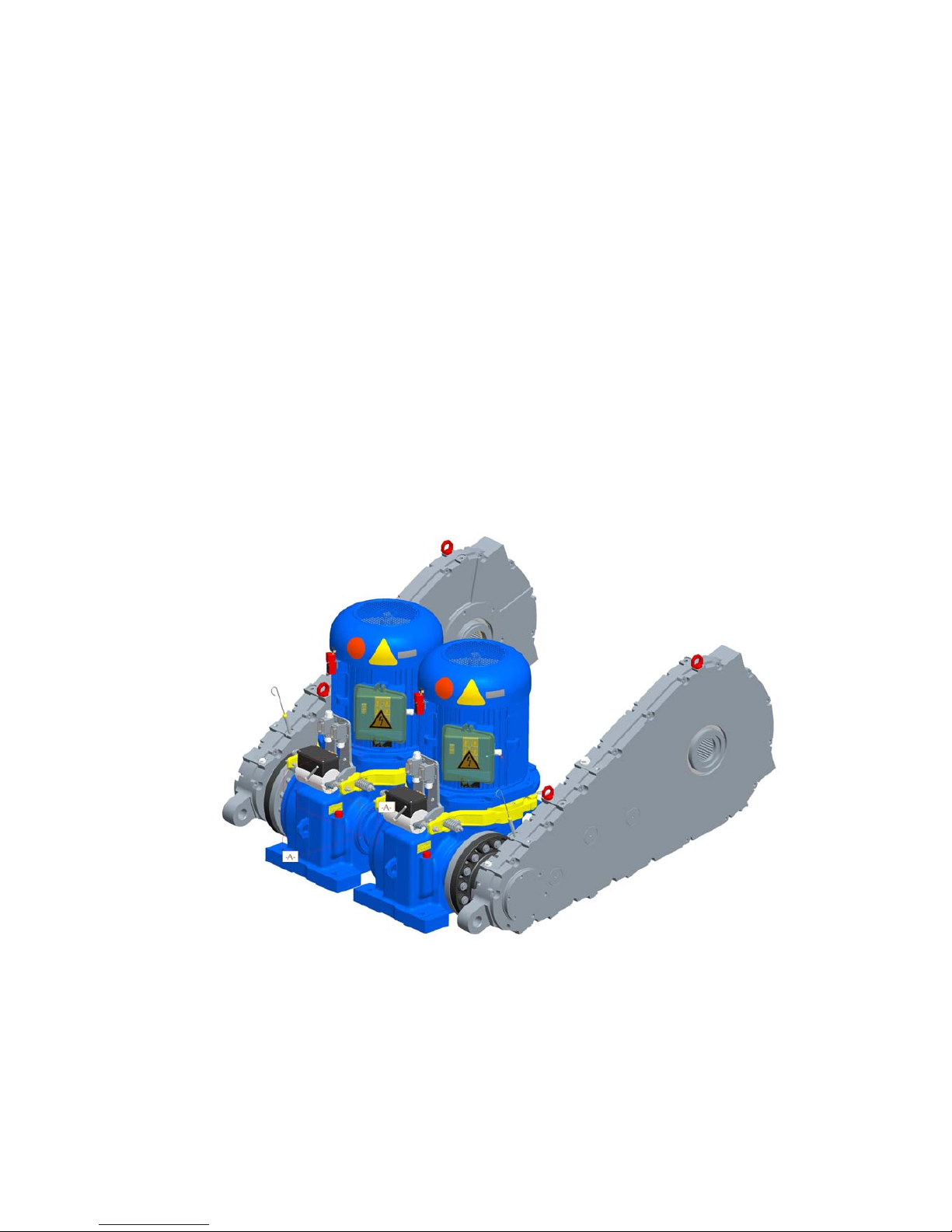
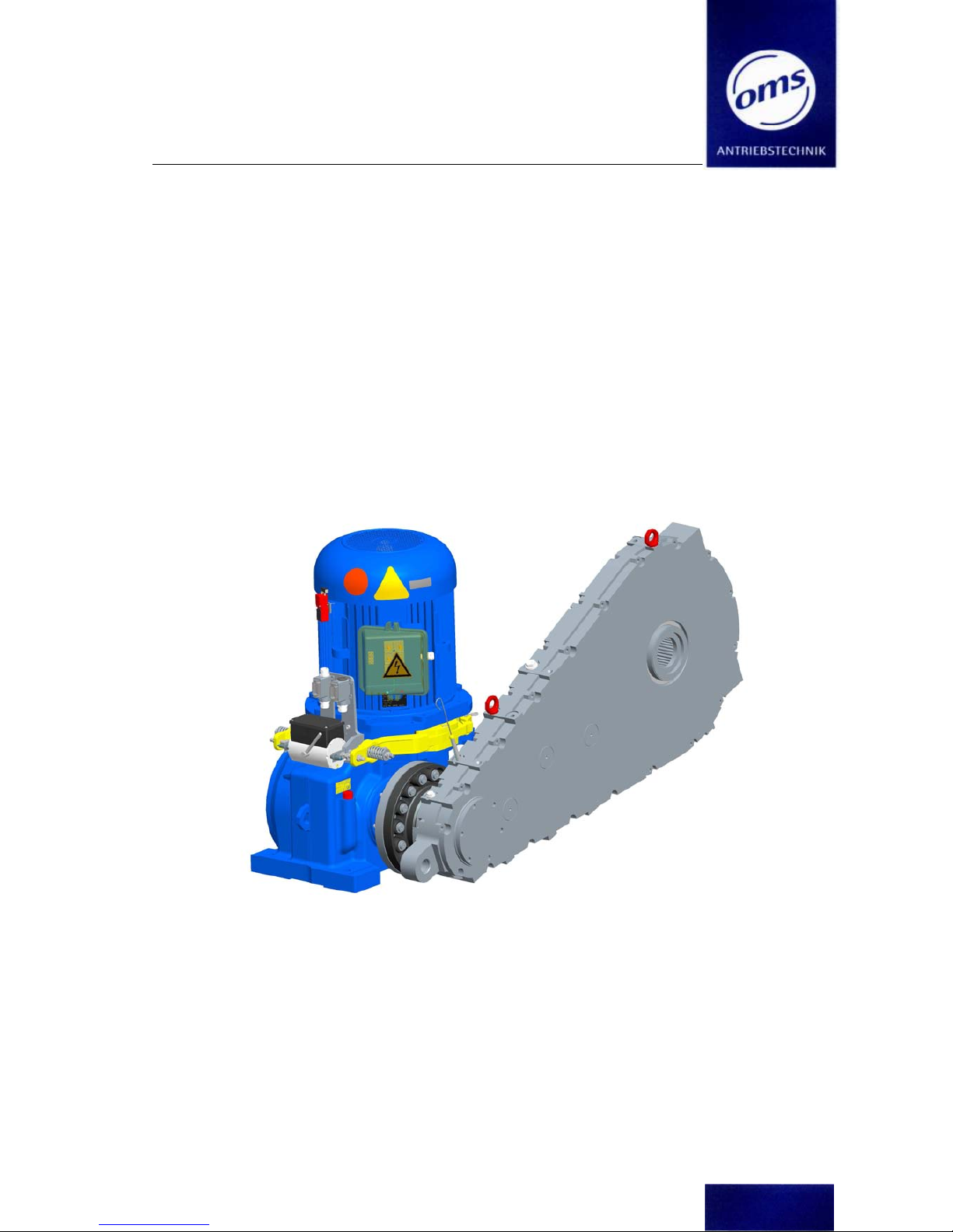
Fig. 4a EC 2-25 Coupling machine, consisting of 1x Drive unit, 1x Intermediate coupling und 1x
Intermediate gear
Installation instructions EC 2 - 25
Coupling Machine, Duplex Machine , Dual Machine
(Technical changes reserved – Last Changes 10/2018)
Page 20 of 89
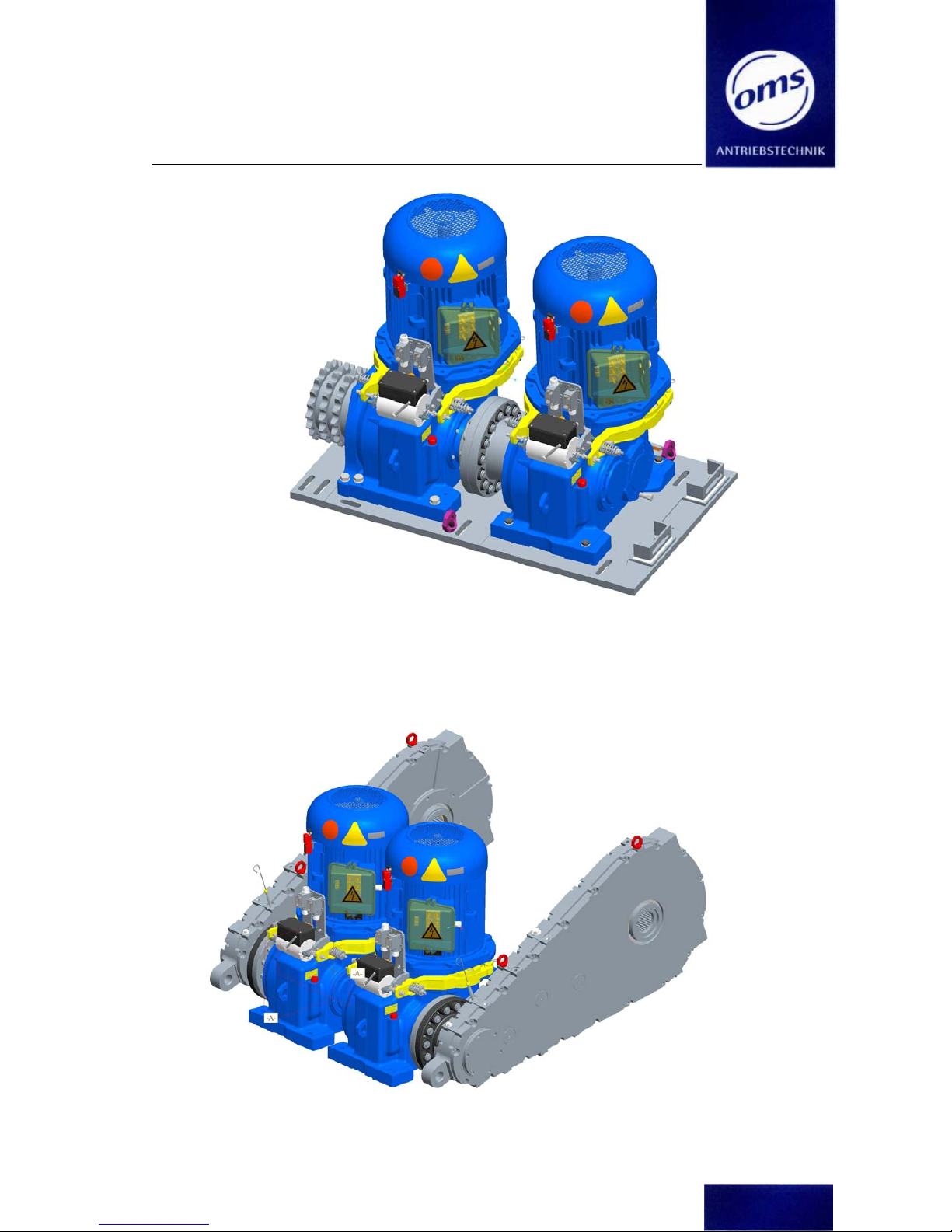
Fig. 4b : Dual machine, consisting of 2x Drive unit, 1xIntermediate coupling, 1xBasic plate and
1x Chain wheel
Annotation for fastening the gear boxes onto the basic plate :
Torque for the screws : M20 - 8.8 : 320Nm ; M16 - 8.8 : 180Nm
Fig. 4c : EC 2-25 Dulex machine, consisting of 2x Drive unit, 2x Intermediate coupling. und 2x
Intermediate gear
Installation instructions EC 2 - 25
Coupling Machine, Duplex Machine , Dual Machine
(Technical changes reserved – Last Changes 10/2018)
Page 21 of 89
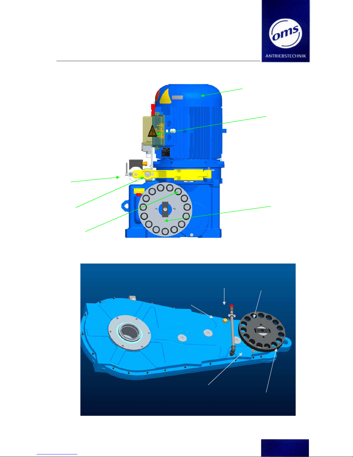
Fig. 4d: Design of the OMS machine EC 2-25 with intermediate coupling
Abb. 4e: Design of the OMS-Intermediate gear ZG
Han
d-
wheel
Brake functio
n
control
Brake lining
control
Motor junction
box
Coupling flange
with bolts
Speed sensors
Oil dipstick
Air ventilation
screw
Coupling flange
Whole for bearing
INA- GE25
Oil drain plug
Installation instructions EC 2 - 25
Coupling Machine, Duplex Machine , Dual Machine
(Technical changes reserved – Last Changes 10/2018)
Page 22 of 89
4.1 Technical Data
Please refer to the Appendix for details of the OMS escalator machine’s working capacity, sheet:
„Technical data for escalator machine EC 2 – 25“.
All dimensions and connecting dimensions for the OMS escalator machine are given in the Appendix:
„Dimensioned drawing of the escalator machine EC 2 - 25“.
4.2 Noise Emission Information
The A-weighted sound pressure level LpA in dB(A), measured according to DIN EN ISO 11200 is
measure at 1 m distance to the traction machines surface.
The traction machines will meet the below sound emission figure under the condition of an
empty running escalator:
Machine type
Max. sound emission L
pA
[ dB(A) ]
EC 2
- 25
without intermediate gear
typ.
64,0 at motor speed < 1.500 min
–
1
25% load
dependet on performance and application
If you have any further questions regarding noise emissions, please contact OMS.
4.3 Manufacturers Identification Plate
The following information can found on the manufacturers identification plate. For Example:
Model: EC 2 - 25
Ratio:
OMS-No. – Month Year xxxx-mmyy
OMS ANTRIEBSTECHIK
36219 CORNBERG
GERMANY
EC 2 - 25
OMS Nr. - Baujahr xxxx-MMJJ
OMS-Auftrag: xxxxxx
Kommission: xxxxxxxxx
Übersetzung: 19,99/1

Installation instructions EC 2 - 25
Coupling Machine, Duplex Machine , Dual Machine
(Technical changes reserved – Last Changes 10/2018)
Page 23 of 89
Zwischengetriebe
OMS-Number
Contract Number
Delivery Date
Type of gear
Ratio
OMS Antriebstechnik
36269 Cornberg
Germany
OMS-No.: ZG .xxxxxx
Unit-No.: xxxxxxx
Deliv. Date : Month Year
Type : ZG / D x
Ratio : i = xx : 1
Installation instructions EC 2 - 25
Coupling Machine, Duplex Machine , Dual Machine
(Technical changes reserved – Last Changes 10/2018)
Page 24 of 89
4.4 Modules and Additional Parts
The OMS escalator machine EC 2 - 25 consists of:
• Gear, compl.
• Motor, compl. (with Hand wheel and brake drum)
• Brake system, compl. (solenoid, brake levers, brake spring, rod)
• Function monitoring devices
- Brake function monitoring (optional)
- Brake lining wear monitoring (optional)
• Safety devices
Speed sensors (NRD monitoring) (optional)
• Intermediate gear ZG
4.5 Alternative equipment
The escalator machines can also be fitted with the following alternative components:
• Gearbox ratio: i = 18,7 ; 20 ; 22,4 ; 24
• Motor selection
Standard-features:
• Terminal box with metric thread
• 3 Winding earthing contact (bimetal opener)
• Colour: gentian blue RAL 5010,
• Protection class IP 55
• Motor power S1 operation
4-
pole 50Hz (1500rpm)
6- pole 50Hz (1000rpm)
6- pole 60Hz (1
200rpm)
11,7 kW
11,7 kW
11,7 kW
15 kW
15 kW
15 kW
18,6 kW
18,6 kW
18,6 kW
24 kW
22 kW
24 kW
30 kW
27 kW
• Switching impulse voltage test 2 x U
B
+1000V (1min Test time)
od. (2 x UB + 1000V) +20% 1sec. Test time
• Brake drum and hand wheel assembled
• Motor shaft and BS end shield provided for magnetic encoders (9 tapped holes M4)
Motor voltage
Installation instructions EC 2 - 25
Coupling Machine, Duplex Machine , Dual Machine
(Technical changes reserved – Last Changes 10/2018)
Page 25 of 89
50 Hz
60Hz
200 - 208 V 200 - 208 V
220 - 240 V 220 V
350 V
380 - 415 V 380 V
440 V 440 V
460 - 480 V 460 - 480 V
575 - 600 V
4.6 Spare parts
The following components can be exchanged:
• Gear housing
Exchange gearbox
Sealing kit input shaft
Coupling, elastic clutch gasket
Sprocket wheel
Oil dipstick, Gearbox oil
• Motor, complete (including Hand wheel, Brake drum, claw coupling)
• Brake
Brake solenoid in size O 31(single circuit) - O 32, O 33 double circuit)
Brake lever pair with brake lining
Spring single circuit/ springs - dual circuit
Brake lever bolts
• Sensor technology
Over and underspeed controls
Brake lining wear control
Braking function controls

Installation instructions EC 2 - 25
Coupling Machine, Duplex Machine , Dual Machine
(Technical changes reserved – Last Changes 10/2018)
Page 26 of 89
5 Transport and Storage
5.1 Transport
All machines are inspected and passed prior to leaving our factory site.
When you accept delivery of your machine, please check the packaging for signs of exterior
damage. If you find damage which appears to have been caused in transit, then please document this damage in the presence of the delivery agent. The machine may not be taken into service.
The Machine leaves the OMS factory in an Oil tight state. If the Machine has to be transported
after having been installed, then the oil Dipstick and/or Air Bleeder Valve must be removed and
replaced with the original OMS Oil Sealing Plugs. If the plugs are not available, please order new
sealing plugs from OMS.
The total weight from the machine depends from the motor power.
Gearbox weight separate : approx. 400 kg
Motor weight by BG 160 : approx. 160 – 200 kg
Motor weight by BG 180 : approx. 200 - 300 kg
Motor weight by BG 225 : approx. 300 - 340 kg
Intermediate gear ZG : approx : 500-520kg
Installation instructions EC 2 - 25
Coupling Machine, Duplex Machine , Dual Machine
(Technical changes reserved – Last Changes 10/2018)
Page 27 of 89
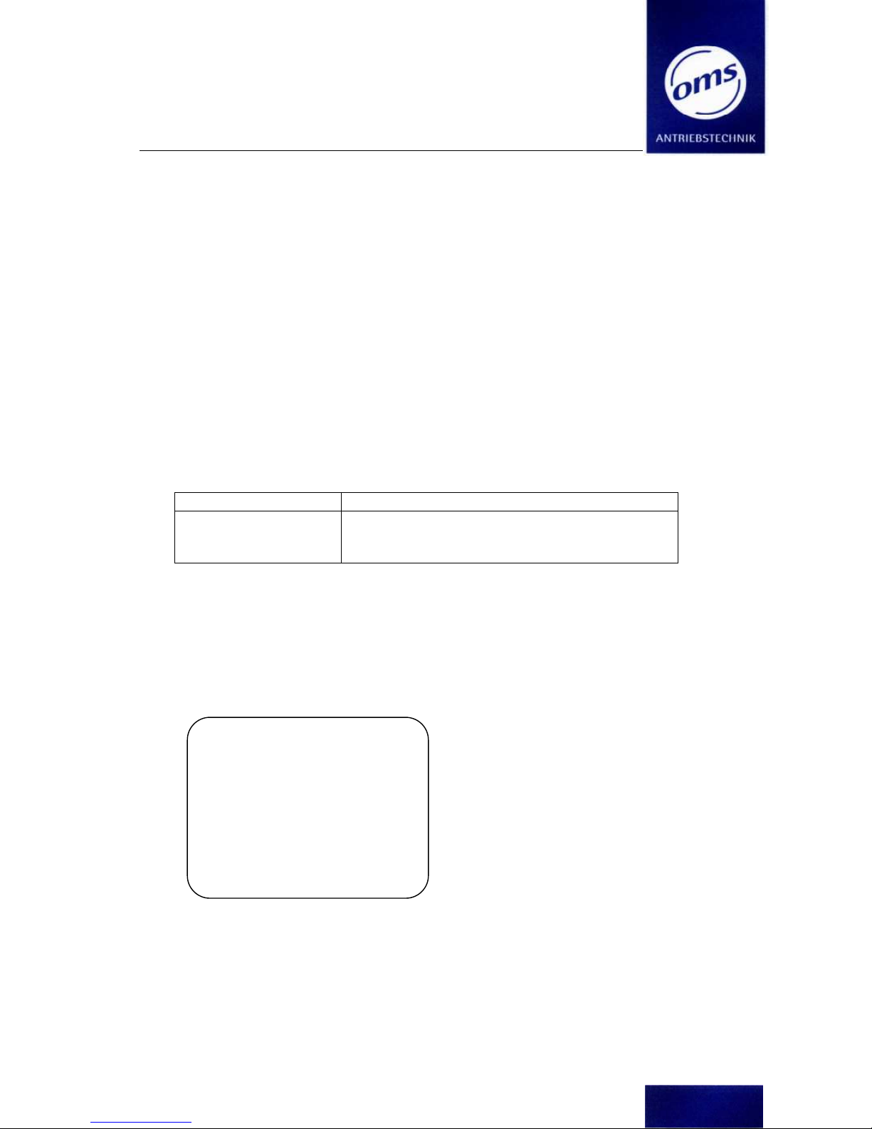
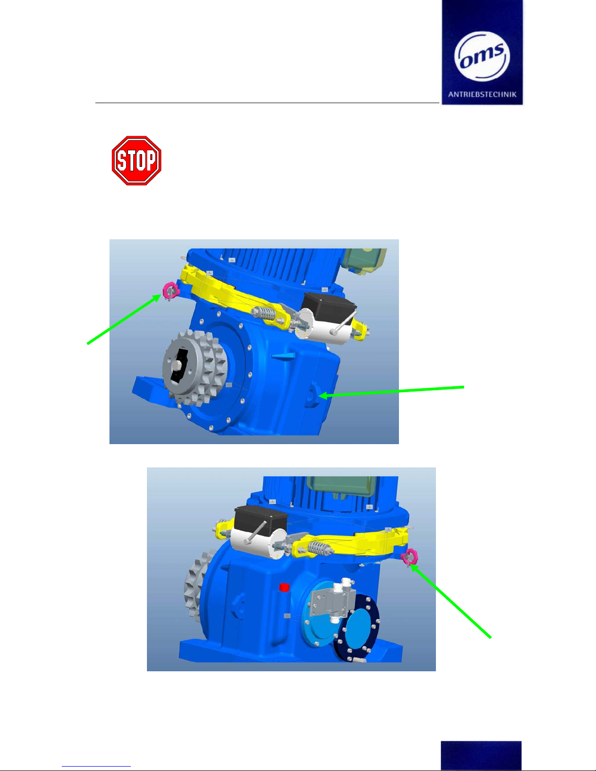
5.2 Lifting the machine
Always use the appropriate lifting tackle to lift the elevator m
a-
chine, otherwise it may fall!
Only high strength eyebolts may be used to lift the gear unit!
The gear housing is equipped with threaded holes for eyebolts (4x
M12).
Lifting the gear unit using the eyebolts on the motor is prohibited
as these are
only designed to
carry the weight of the motor!
Fig. 5a
 Loading...