

Omron ZX-LD100, ZX-LD40L, ZX-LDA41, ZX-LD40, ZX-LD100L Operation Manuals
...
Smart Sensors
ZX Series
Operation Manual
OMRON Corporation
Cat. No. Z157-E1-02

Introduction
Thank you for purchasing an OMRON ZX-series Smart Sensor. We hope you will
fully utilize this product and its performance for many years to come.
The ZX-series Smart Sensor is a laser product designed specifically as a sensing
device. To ensure safety, read this manual carefully before using the Sensor. In
addition, keep this manual in an easily accessible location for quick reference
when needed.

READ AND UNDERSTAND THIS DOCUMENT
Please read and understand this document before using the products. Please consult your
OMRON representative if you have any questions or comments.
WARRANTY
OMRON’s exclusive warranty is that the products are free from defects in materials and
workmanship for a period of one year (or other period if specified) from date of sale by
OMRON.
OMRON MAKES NO WARRANTY OR REPRESENTATION, EXPRESS OR IMPLIED,
REGARDING NON-INFRINGEMENT, MERCHANTABILITY, OR FITNESS FOR
PARTICULAR PURPOSE OF THE PRODUCTS. ANY BUYER OR USER
ACKNOWLEDGES THAT THE BUYER OR USER ALONE HAS DETERMINED THAT THE
PRODUCTS WILL SUITABLY MEET THE REQUIREMENTS OF THEIR INTENDED USE.
OMRON DISCLAIMS ALL OTHER WARRANTIES, EXPRESS OR IMPLIED.
LIMITATIONS OF LIABILITY
OMRON SHALL NOT BE RESPONSIBLE FOR SPECIAL, INDIRECT, OR
CONSEQUENTIAL DAMAGES, LOSS OF PROFITS OR COMMERCIAL LOSS IN ANY
WAY CONNECTED WITH THE PRODUCTS, WHETHER SUCH CLAIM IS BASED ON
CONTRACT, WARRANTY, NEGLIGENCE, OR STRICT LIABILITY.
In no event shall responsibility of OMRON for any act exceed the individual price of the
product on which liability is asserted.
IN NO EVENT SHALL OMRON BE RESPONSIBLE FOR WARRANTY, REPAIR, OR
OTHER CLAIMS REGARDING THE PRODUCTS UNLESS OMRON’S ANALYSIS
CONFIRMS THAT THE PRODUCTS WERE PROPERLY HANDLED, STORED,
INSTALLED, AND MAINTAINED AND NOT SUBJECT TO CONTAMINATION, ABUSE,
MISUSE, OR INAPPROPRIATE MODIFICATION OR REPAIR.
SUITABILITY FOR USE
THE PRODUCTS CONTAINED IN THIS DOCUMENT ARE NOT SAFETY RATED. THEY
ARE NOT DESIGNED OR RATED FOR ENSURING SAFETY OF PERSONS, AND
SHOULD NOT BE RELIED UPON AS A SAFETY COMPONENT OR PROTECTIVE
DEVICE FOR SUCH PURPOSES. Please refer to separate catalogs for OMRON's safety
rated products.
OMRON shall not be responsible for conformity with any standards, codes, or regulations
that apply to the combination of products in the customer’s application or use of the product.
At the customer’s request, OMRON will provide applicable third party certification
documents identifying ratings and limitations of use that apply to the products. This
information by itself is not sufficient for a complete determination of the suitability of the
products in combination with the end product, machine, system, or other application or use.
The following are some examples of applications for which particular attention must be
given. This is not intended to be an exhaustive list of all possible uses of the products, nor is
it intended to imply that the uses listed may be suitable for the products:
Outdoor use, uses involving potential chemical contamination or electrical interference, or
conditions or uses not described in this document.
Nuclear energy control systems, combustion systems, railroad systems, aviation systems,
medical equipment, amusement machines, vehicles, safety equipment, and installations
subject to separate industry or government regulations.
Systems, machines, and equipment that could present a risk to life or property.

Please know and observe all prohibitions of use applicable to the products.
NEVER USE THE PRODUCTS FOR AN APPLICATION INVOLVING SERIOUS RISK TO
LIFE OR PROPERTY WITHOUT ENSURING THAT THE SYSTEM AS A WHOLE HAS
BEEN DESIGNED TO ADDRESS THE RISKS, AND THAT THE OMRON PRODUCT IS
PROPERLY RATED AND INSTALLED FOR THE INTENDED USE WITHIN THE OVERALL
EQUIPMENT OR SYSTEM.
PERFORMANCE DATA
Performance data given in this document is provided as a guide for the user in determining
suitability and does not constitute a warranty. It may represent the result of OMRON’s test
conditions, and the users must correlate it to actual application requirements. Actual
performance is subject to the OMRON Warranty and Limitations of Liability.
CHANGE IN SPECIFICATIONS
Product specifications and accessories may be changed at any time based on
improvements and other reasons.
It is our practice to change model numbers when published ratings or features are changed,
or when significant construction changes are made. However, some specifications of the
product may be changed without any notice. When in doubt, special model numbers may be
assigned to fix or establish key specifications for your application on your request. Please
consult with your OMRON representative at any time to confirm actual specifications of
purchased products.
DIMENSIONS AND WEIGHTS
Dimensions and weights are nominal and are not to be used for manufacturing purposes,
even when tolerances are shown.
ERRORS AND OMISSIONS
The information in this document has been carefully checked and is believed to be accurate;
however, no responsibility is assumed for clerical, typographical, or proofreading errors, or
omissions.
PROGRAMMABLE PRODUCTS
OMRON shall not be responsible for the user’s programming of a programmable product, or
any consequence thereof.
COPYRIGHT AND COPY PERMISSION
This document shall not be copied for sales or promotions without permission.
This document is protected by copyright and is intended solely for use in conjunction with
the product. Please notify us before copying or reproducing this document in any manner,
for any other purpose. If copying or transmitting this document to another, please copy or
transmit it in its entirety.
For You r Safety
For Your Safety
Notation for Safety Information
The following conventions are used to indicate and classify precautions in
this manual. Always heed the information provided with them. Failure to
heed precautions can result in injury to people or damage to property.
Indicates a potentially hazardous situation
which, if not avoided, will result in minor or
moderate injury, or may result in serious
injury or death. Additionally there may be
significant property damage.
Indicates a potentially hazardous situation
which, if not avoided, may result in minor or
moderate injury, or in property damage.
i

Laser Safety
Laser Safety
The ZX-LD@@, ZX-LD@@L, ZX-LD@@V, and ZX-LD@@VL Sensor Heads
are Class 2 Laser Products according to EN60825-1 (IEC825-1) and Class
II Laser Products according to FDA (21 CFR1040.10) (see note). The ZXLT @@@ Sensor Heads are Class 1 and Class II Laser Products, respec-
tively. The ZX Series is meant to be built into final system equipment. Pay
special attention to the following precautions for the safe use of the product:
Note: Europe: Class 1 and Class 2 of EN60825-1: 1994 = IEC825-1: 1993
U.S.A.: Class I and Class II of FDA (21 CFR1040.10)
(1) Use this product as specified in this operation manual. Otherwise, you may
be exposed to hazardous laser radiation.
(2) The ZX-series Smart Sensors radiate laser beams in the visible light range.
Do not expose your eyes directly to the laser radiation. Ensure that the laser
beam path is terminated during use. If a mirror or shiny surface is positioned
in the laser beam path, ensure that the reflected beam path is also terminated. If the Unit must be used without terminating the laser beam path, position the laser beam path so that it is not at eye level.
(3) To avoid exposure to hazardous laser radiation, do not displace nor remove
the protective housing during operation, maintenance, and any other servic-
ing.
(4) The user should return the product to OMRON for all repair and servicing.
(5) As for countries other than those of Europe and the U.S.A., observe the regu-
lations and standards specified by each country.
ii

Laser Safety
Requirements from Regulations and Standards
EN60825-1 “Safety of Laser Products, Equipment
Classification, Requirements and User’s Guide”
• Summary of Manufacturer’s Requirements
Requirements;
Sub-clause
Description of
hazard class
Protective
housing
Safety interlock
in protective
housing
Remote control Not required Permits easy addition of external
Key control Not required Laser inoperative when key is re-
Emission warning device
Attenuator Not required Gives means beside ON/OFF
Location controls
Viewing optics Emission from all viewing systems must be below Class 1 AEL’s as applicable
Scanning Scan failure shall not cause product to exceed its classification
Class label Required
Aperture label Not required Specified wording required
Service entry label
Override interlock label
User information
Purchasing and
service information
Medical products
Fibre optic Cable service connections requ ire tool to disconnect if disconnection brea ks protective
Class 1 Class 2 Class 3A Class 3B* Class 4
Safe under
reasonably
foreseeable
conditions
Required for each laser product; limits access necessary for performance of functions
of the products
Designed to prevent removal of the panel until accessible emission values are below
the AEL (see note 2) for the class assigned
Not required Gives audible or visible warning
Not required Controls so located that there is no danger of expo-
wording
Required as appropriate to the class of accessible radiation
Required under certain conditions as appropriate to the class of laser used
Operation manuals must contain instructions for safe use
Promotion brochures must reproduce classification labels; service manuals must contain safety information
Special calibration instructions required Special calibration instructions,
housing and permits access above Class 1
Low power;
eye protection
normally afforded by aversion responses
Figures A and B and specified wording
Classification
Same as Class
2. Direct intrabeam viewing
with optical
aids may be
hazardous
sure to AEL above Classes 1 or 2 when adjustments are made.
Direct intrabeam viewing
may be hazardous
interlock in laser installation
moved
when laser is switched on or if capacitor bank of pulsed laser is being charged
switch to temporarily block beam
means for measurement and target-indicator required
High power; diffused reflection
may be hazardous
*With respect to the requirements of remote interlock connector, key control, emission warning and attenuator, Class 3B laser products not exceeding five times the AEL of Class 2 in the wavelength range of 400 nm to 700
nm are to be treated as Class 3A laser products.
iii

Laser Safety
Note 1. The above table is intended to provide a convenient summary of
requirements. See text of this standard for complete requirements.
2. AEL: Accessible Emission Limit
The maximum accessible emission level permitted within a particular
class. For your reference, see ANSI Z136.1-1993, Section 2.
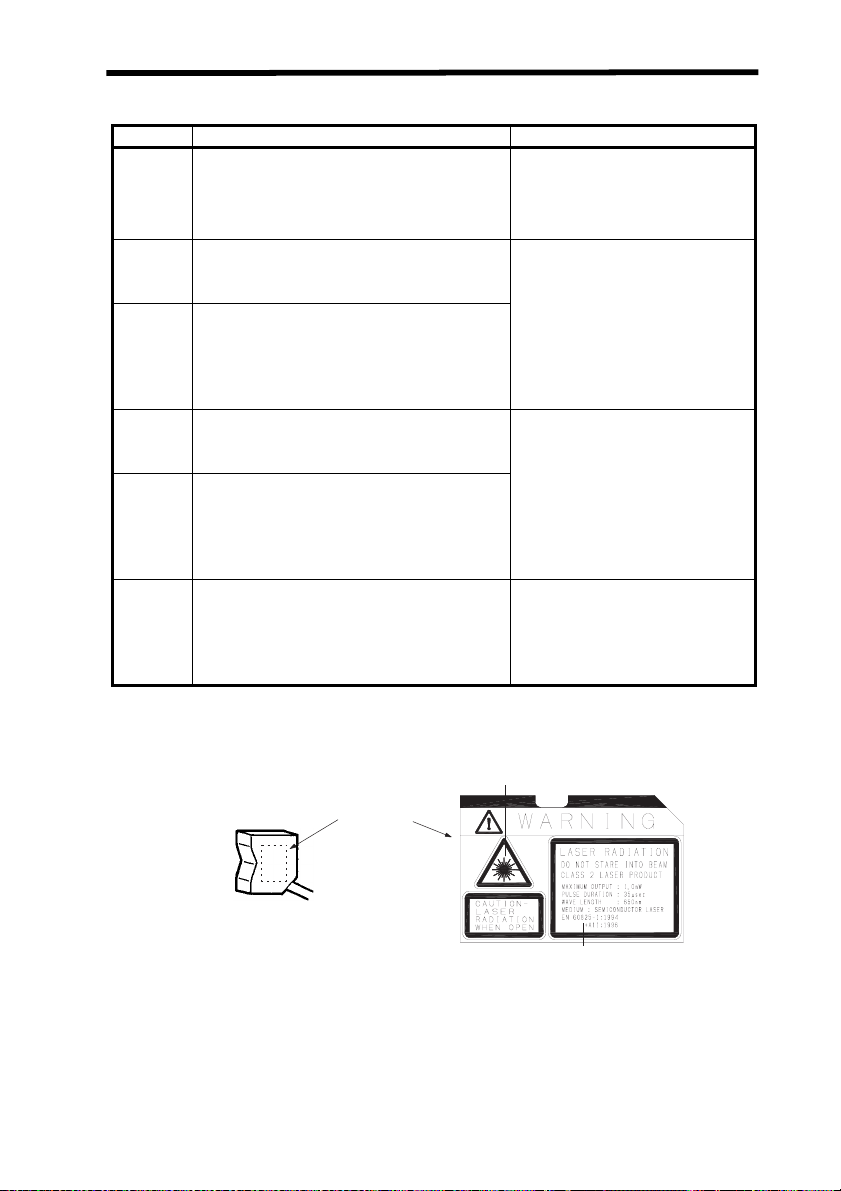
Symbol and border: black
Background: yellow
Figure A Warning label - Hazard symbol
Legend and border: black
Background: yellow
Figure B Explanatory label
• FDA (Compliance Guide for Laser Products, 1985, according
to 21 CFR1040.10)
Requirements Class (see note 1)
I IIa II IIIa IIIb IV
Performance (all laser products)
Protective housing
Safety interlock R (see
Location of controls
Viewing opticsRRRRRR
Scanning safeguard
Performance (laser systems)
R
(see note 2)R (see note 2)R (see note 2)R (see note 2)R (see note 2)R (see note 2)
notes 3, 4)
N/A R R R R
RRRRRR
R (see
notes 3, 4)
R (see
notes 3, 4)
R (see
notes 3, 4)
R (see
notes 3, 4)
R (see
notes 3, 4)
iv

Laser Safety
Requirements Class (see note 1)
I IIa II IIIa IIIb IV
Remote control
connector
Key control N/A N/A N/A N/A R R
Emission indicator
Beam attenuator N/A N/A R R R R
Reset N/A N/A N/A N/A N/A R
Performance (specific purpose products)
MedicalSSSS
Surveying, leveling, alignment
DemonstrationSSSSS
Labeling (all laser products)
Certification &
identification
Protective housing
ApertureN/AN/ARRRR
Class warning N/A R
Information (all laser products)
User informationRRRRRR
Product literatureN/ARRRRR
Service information
Abbreviations:
R: Required.
N/A: Not applicable.
S: Requirements: Same as for other products of that Class.
Also see footnotes.
NP: Not permitted.
D: Depends on level of interior radiation.
Footnotes:
N/A N/A N/A N/A R R
N/AN/ARRR
(See note
8.)
SSSSNPNP
RRRRRR
D
(See note
5.)
RRRRRR
D
(See Note
5.)
(See note
6.)
D
(See note
5.)
R
(See note
7.)
D
(See note
5.)
R
(See note
9.)
(See note
10.)
S
(See note
8.)
(See note
11.)
D
(See note
5.)
R
(See note
12.)
R
(See note
10.)
(See note
13.)
S
(See note
8.)
S
(See note
11.)
D
(See note
5.)
R
(See note
12.)
1. Based on highest level accessible during operation.
2. Required wherever & whenever human access to laser radiation above Class
I limits is not needed for product to perform its function.
3. Required for protective housings opened during operation or maintenance, if
human access thus gained is not always necessary when housing is open.
4. Interlock requirements vary according to Class of internal radiation.
5. Wording depends on level & wavelength of laser radiation within protective
housing.
v

Laser Safety
6. Warning statement label.
7. CAUTION logotype.
8. Requires means to measure level of laser radiation intended to irradiate the
9. CAUTION if 2.5 mW cm
10.Delay required between indication & emission.
11.Variance required for Class IIb or IV demonstration laser products and light
12.DANGER logotype.
13.Required after August 20, 1986.
Use Precautions
• EN60825-1
body.
shows.
2
or less, DANGER if greater than 2.5 mW cm–2.
Requirements;
Sub-clause
Remote interlock Not required Connect to room or door circuits
Key control Not required Remove key when not in use
Beam attenuator Not required When in use prevents inadvert-
Emission indicator device
Warning signs Not required Follow precautions on warning
Beam path Not required Terminate beam at end of useful length
Specular reflection
Eye protection No requirements Required if engineering and administrative proce-
Protective clothing
Training No requirements Required for all operator and maintenance per-
Class 1 Class 2 Class 3A Class 3B* Class 4
Not required Indicates laser is energized
No requirements Prevent unintentional reflec-
No requirements Sometimes re-
Classification
ent exposure
signs
tions
dures not practicable and MPE exceeded
quired
sonnel
Specific requirements
*With respect to the requirements of remote interlock connector, key control, beam attenuator, and emission indicator, Class 3B laser products not
exceeding five times the AEL of Class 2 in the wavelength range of 400 nm
to 700 nm are to be treated as Class 3A laser products.
Note: This table is intended to provide a convenient summary of requirements.
See text of this standard for complete precautions.
• ANSI Z136.1:1993 “American National Standard for the Safe
Use of Lasers” Control Measures for the Four Laser Classes
Control measures Classification
Engineering Controls 1 2a 2 3a 3b 4
Protective Housing (4.3.1) X X X X X X
Without Protective Housing
(4.3.1.1)
LSO (see note 2) shall establish Alternate Controls
vi

Laser Safety
Control measures Classification
Interlocks on Protective Housing
(4.3.2)
Service Access Panel (4.3.3) ✩ ✩✩✩XX
Key Control (4.3.4) --- --- --- --- • X
Viewing Portals (4.3.5.1) --- --- MPE MPE MPE MPE
Collecting Optics (4.3.5.2) MPE MPE MPE MPE MPE MPE
Totally Open Beam Path (4.3.6.1) --- --- --- --- X
Limited Open Beam Path (4.3.6.2) --- --- --- --- X
Enclosed Beam Path (4.3.6.3) None is required if 4.3.1 and 4.3.2 fulfilled
Remote Interlock Connector
(4.3.7)
Beam Stop or Attenuator (4.3.8) --- --- --- --- • X
Activation Warning Systems
(4.3.9)
Emission Delay (4.3.9.1) --- --- --- --- --- X
Indoor Laser Controlled Area
(4.3.10)
Class 3b Laser Controlled Area
(4.3.10.1)
Class 4 Laser Controlled Area
(4.3.10.2)
Laser Outdoor Controls (4.3.11) --- --- --- --- X
Laser in Navigable Airspace
(4.3.11.2)
Temporary Laser Controlled Area
(4.3.12)
Remote Firing & Monitoring
(4.3.13)
Labels (4.3.14 and 4.7) XXXXXX
Area Posting (4.3.15) --- --- --- • X
Administrative & Procedural Controls
Standard Operating Procedures
(4.4.1)
Output Emission Limitations (4.4.2) --- --- --- LSO Determination
Education and Training (4.4.3) --- --- • • X X
Authorized Personnel (4.4.4) --- --- --- --- X X
Alignment Procedures (4.4.5) --- --- X X X X
Protective Equipment (4.4.6) --- --- --- --- • X
Spectator (4.4.7) --- --- --- --- • X
Service Personnel (4.4.8) ✩
Demonstration with General Public
(4.5.1)
Laser Optical Fiber Systems
(4.5.2)
Laser Robotic Installations (4.5.3) --- --- --- --- X
✩✩✩✩XX
NHZ
NHZ
--- --- --- --- • X
--- --- --- --- • X
--- --- --- --- X
--- --- --- --- X ---
--- --- --- --- --- X
--- --- --- • • •
✩
MPE
--- --- --- --- --- •
12a23a3b4
--- --- --- --- • X
MPE
MPE ✝ ---XXXX
MPE MPE MPE MPE X X
✩
MPE✩MPE✩MPE
✩
MPE✩MPE✩MPE
NHZ
NHZ
--- ---
NHZ
XX
NHZ
X
NHZ
X
NHZ
X
NHZ
X
NHZ
X
NHZ
X
NHZ
vii

Laser Safety
Control measures Classification
Eye Protection (4.6.2) --- --- --- --- •
Protective Windows (4.6.3) --- --- --- --- X
Protective Barriers and Curtains
(4.6.4)
Skin Protection (4.6.5) --- --- --- --- X
Other Protective Equipment (4.6.5) Use may be required
Warning Signs and Labels (4.7)
(Design Requirements)
Service and Repairs (4.8) LSO Determination
Modification of Laser Systems
(4.9)
--- --- --- --- • •
--- --- • • X
LSO Determination
Note 1. LEGEND
X: Shall
•: Should
---: No requirement
✩: Shall if enclosed Class 3b or Class 4
MPE: Shall if MPE is exceeded
NHZ: Nominal Hazard Zone analysis required
✝: Applicable only to UV and IR Lasers (4.5.1.2)
2. LSO: Laser Safety Officer
An individual shall be designated the Laser Safety Officer with the authority
and responsibility to monitor and enforce the control of laser hazards, and to
effect the knowledgeable evaluation and control of laser hazards.
For your reference, see ANSI Z136.1-1993, Section 1.3.
Laser Product Classifications
MPEXMPE
NHZ
MPEX MPE
NHZ
X
NHZ
X
NHZ
•EN
Class Description
Class 1 Lasers which are safe under reasonably foreseeable conditions of operation.
Class 2 Lasers emitting visible radiation in the wavelength range from 400 nm to 700 nm.
Class 3A Lasers which are safe for viewing with the unaided eye. For laser emitting in the
Class 3B Direct intrabeam viewing of these lasers is always hazardous. Viewing diffuse re-
Class 4 Lasers which are also capable of producing hazardous diffuse reflections. They
Eye protection is normally afforded by aversion responses including the blink reflex.
wavelength range from 400 nm to 700 nm, protection is afforded by aversion responses including the blink reflex. For other wavelengths the hazard to the unaided eye is no greater than for Class 1. Direct intrabeam viewing of Class 3A lasers
with optical aides (e.g., binoculars, telescopes, microscopes) may be hazardous.
flections is normally safe (see note).
may cause skin injuries and could also constitute a fire hazard. Their use requires
extreme caution.
Note: Conditions for safe viewing of diffuse reflections for Class 3B visible
lasers are: minimum viewing distance of 13 cm between screen and cornea and a maximum viewing time of 10 s. Other viewing conditions
require a comparison of the diffuse reflection exposure with the MPE.
viii
Laser Safety
Comparison of Classifications between FDA and ANSI
Class FDA definition ANSI description
Class I/1 Limits applicable to devices that have emissions in
Class IIa/2aLimits applicable to products whose visible emis-
Class II/2 Limits applicable to products that have emissions
Class IIIa/3aLimits to products that have emissions in the visi-
Class IIIb/3bLimits applicable to devices that emit in the ultra-
Class IV/4 Exceeding the limits of Class IIIb and are a hazard
the ultraviolet, visible, and infrared spectra, and
limits below which biological hazards have not
been established.
sion does not exceed Class I limits for emission
durations of 1,000 seconds or less and are not intended for viewing.
in the visible spectrum (400 to 710 nm) for emission durations in excess of 0.25 second, providing
that emissions for other durations and/or wavelengths do not exceed the Class I limits. Class II
products are considered hazardous for direct
long-term ocular exposure.
ble spectrum and that have beams where the total
collectable radiant power does not exceed 5 milliwatts.
violet, visible, and infrared spectra. Class IIIb
products include laser systems ranging from 5 to
500 milliwatts in the visible spectrum. Class IIIb
emission levels are ocular hazards for direct exposure throughout the range of the Class, and skin
hazards at the higher levels of the Class.
for scattered reflection as well as for direct exposure.
A Class 1 laser is considered to be incapable of producing damaging radiation levels during operation and
maintenance and is, therefore, exempt from any control measures or
other forms of surveillance.
Class 2 lasers are divided into two
subclasses, 2 and 2a. A Class 2 laser
emits in the visible portion of the spectrum (0.4 to 0.7
tion is normally afforded by the
aversion response including the blink
reflex.
Class 3 lasers are divided into two
subclasses, 3a and 3b. A Class 3 laser may be hazardous under direct
and specular reflection viewing conditions, but the diffuse reflection is usually not a hazard.
A Class 4 laser is a hazard to the eye
or skin from the direct beam and
sometimes from a diffuse reflection
and also can be a fire hazard. Class 4
lasers may also produce laser-generated air contaminants and hazardous
plasma radiation.
µm) and eye protec-
Label Indications
•EN
EN/IEC warning label
Laser warning label
Explanatory label with specified wording
Note: Use of controls, adjustments, or procedures other than those specified
herein may result in hazardous radiation exposure.
ix

Laser Safety
•FDA
Caution
logo type
Certification and
identification label
Aperture label
Note: Use of controls, adjustments, or procedures other than those specified here-
in may result in hazardous radiation exposure.
Aperture Label
Certification and Identification Label
Class II Caution logo type
x

Precautions
Precautions
Ratings and Performance
(1) Conform to the specified ratings and performance.
Refer to "6-1 Ratings/Specifications"
• Do not impose voltage exceeding the rated voltage, otherwise the Sensor may be damaged.
• When supplying power to the Sensor, make sure that the polarity of the
power is correct, otherwise, the Sensor may be damaged. Do not connect to an AC power supply.
• Do not short-circuit the load for the open collector output, otherwise the
Sensor may be damaged.
(2) Do not disconnect the connector connecting the Sensor Head and the con-
troller while power is being supplied, otherwise the Sensor may be damaged.
(3) Allow a warm-up period of approximately 10 minutes after turning ON the
power supply.
(4) Objects of certain materials or shapes may not be detectable, or the detec-
tion accuracy may not be sufficiently high. These include materials that are
transparent or have extremely low reflectivity, and objects that are smaller
than the Sensor’s spot diameter or have extreme curvature or inclination.
Power Supply and Wiring
(1) Prior to turning ON the power supply after wiring is completed, check to make
sure that the power supply is correct, that there are no mistaken connections,
e.g., connections that would short-circuit the load, and that the load current is
appropriate. Incorrect wiring may result in damage to the Sensor or Unit.
(2) The total length of the Sensor cable or Amplifier cable must be 10 m or less.
Use an ZX-XC@A Extension Cable (order separately) if required to extend
the cable from the Sensor. Use a shielded cable to extend the Amplifier
cable. The shielded cable must be the same as that of the Amplifier cable.
(3) Do not lay a power supply cable for the ZX together with high-voltage lines or
power lines to prevent interference, damage, and malfunction.
(4) When using a commercially available switching regulator, ground the FG
(frame ground) terminal.
(5) If the power supply line is subject to surges, connect a surge absorber that
meets the conditions of the usage environment.
(6) When using a Calculating Unit, connect the corresponding linear ground of
the Amplifier Unit.
Environment
(1) Do not use the Sensor in strong electromagnetic fields or in an environment
where the operation of the Sensor is subject to the reflection of intense light
(such as other laser beams or electric arc-welding machines.)
(2) Do not operate the Sensor in the following locations:
• Locations subject to strong vibration.
xi

Precautions
• Locations subject to direct sunlight or near heating equipment.
• Locations subject to high humidity.
• Locations where the Sensor would accumulate dust, dirt, metallic powder, etc.
• Locations subject to corrosive or flammable gases.
• Locations subject to exposure to organic solvents, water, oil, etc.
• Locations subject to strong electromagnetic or electrical fields.
• Locations subject to rapid changes in temperature.
• Locations subject to freezing.
Maintenance
(1) Always turn OFF the power supply before adjusting or removing the Sensor
Head.
(2) Cleaning
Do not use thinners, benzine, acetone, or kerosene for cleaning.
If dust or oil adheres to the filter on the front of the Sensor Head, use the following procedure to clean.
• Use a blower brush (used to clean camera lenses) to blow large dust
particles from the surface. Do not blow the dust away with your mouth.
• Use a soft cloth (for lenses) with a small amount of alcohol to remove the
remaining dust. Do not use a scrubbing action when cleaning because
scratches on the filter could result in Sensor inaccuracy.
Compatibility
All Sensor Heads and Amplifier Units are compatible. Different Sensor
Heads may be purchased at a later date and used with existing Amplifier
Units.
Controlling Mutual Interference
Mutual interference can be prevented when using two Sensor Heads
together, by connecting the ZX-CAL Calculating Unit between the two
Amplifier Units. However, this effect cannot be attained if the laser beam of
one Sensor Head is received when the other Sensor Head is approaching
saturation. When considering the use of the ZX-CAL Calculating Unit to
control mutual interference, confirm the operation with actual Units in
advance.
Applicable standards
• EN61326-1
• Electromagnetic environment: Industrial electromagnetic environment
(EN/IEC 61326-1 Table 2)
• There may be cases that current output or voltage output fluctuate within
±3 times of resolution when a sensor is experienced electromagnetic
interference.
xii

Table of Contents
For Your Safety .................................................................. i
Laser Safety........................................................................ ii
Precautions........................................................................ xi
SECTION 1 Before Use.................................................... 1
1-1 Names of Sensor Parts............................................................................2
1-2 External Amplifier Unit I/O....................................................................5
1-3 I/O Circuit Diagrams ..............................................................................6
1-4 Connections ............................................................................................8
1-5 Installation ............................................................................................11
1-6 Settings Required before Application...................................................15
SECTION 2 Outline of Operation ................................ 19
2-1 Part Names and Functions ....................................................................20
2-2 Outline of Key Operations....................................................................21
2-3 Procedures for Reflective Sensor Heads...............................................22
2-4 Procedures for Through-beam Sensor Heads .......................................24
2-5 Outline of Functions .............................................................................26
SECTION 3 Descriptions of Functions......................... 29
3-1 ZX-L Series ..........................................................................................31
3-2 Hardware Functions..............................................................................34
3-3 Reflective Sensor Heads: RUN Mode Functions ...............................38
3-4 Reflective Sensor Heads: T Mode Functions .....................................41
3-5 Reflective Sensor Heads: FUN Mode Functions................................44
3-6 Through-beam Sensor Heads: RUN Mode Functions........................71
3-7 Through-beam Sensor Heads: T Mode Functions..............................75
3-8 Through-beam Sensor Heads: FUN Mode Functions ........................79
SECTION 4 Operating Procedures ............................ 107
4-1 Display Operations .............................................................................108
4-2 Initial Display .....................................................................................111
4-3 RUN Mode .........................................................................................112
4-4 T (Threshold) Mode............................................................................118
4-5 FUN (Function) Mode ........................................................................124
SECTION 5 Troubleshooting...................................... 141
5-1 Error Displays.....................................................................................142
5-2 Setting Problems.................................................................................144
SECTION 6 Specifications and Dimensions .............. 147
6-1 Ratings/Specifications ........................................................................148
6-2 Dimensions .........................................................................................156
Revision History........................................................... 166
xiii

Visual Aids
The following icons are used to aid you in finding specific types of
information.
Indicates useful information.
POINT
Note: Indicates precautions to be observed during operation.
Indicates section numbers where related information can
be found.
xiv
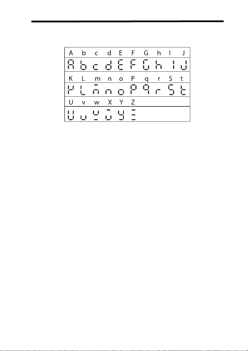
Displayed Form of Alphabet Letters
The letters of the alphabet are displayed digitally in the following forms.
xv

xvi

SECTION 1 Before Use
This section describes preparations that are necessary prior to
switching ON the power supply, such as installation, wiring, and
connections.
1-1 Names of Sensor Parts.......................................................................2
1-1-1 Reflective Sensor Heads.......................................................2
1-1-2 Through-beam Sensor Heads ...............................................3
1-1-3 Amplifier Units .......................................................................4
1-1-4 Calculating Unit .....................................................................4
1-2 External Amplifier Unit I/O...................................................................5
1-3 I/O Circuit Diagrams............................................................................6
1-3-1 NPN Amplifier Unit: ZX-LDA11..............................................6
1-3-2 PNP Amplifier Unit: ZX-LDA41..............................................7
1-4 Connections ........................................................................................8
1-4-1 Sensor Head and Amplifier Unit............................................8
1-4-2 Connecting Cable and Sensor Head.....................................8
1-4-3 Extension Cables ..................................................................9
1-4-4 Amplifier Units and Calculating Unit......................................9
1-5 Installation.........................................................................................11
1-5-1 Reflective Sensor Heads.....................................................11
1-5-2 Through-beam Sensor Heads .............................................12
1-5-3 Amplifier Unit .......................................................................14
1-6 Settings Required before Application................................................15
1-6-1 Auto-scale ...........................................................................15
1-6-2 Reference Incident Level.....................................................16
1-6-3 Linear Output.......................................................................17
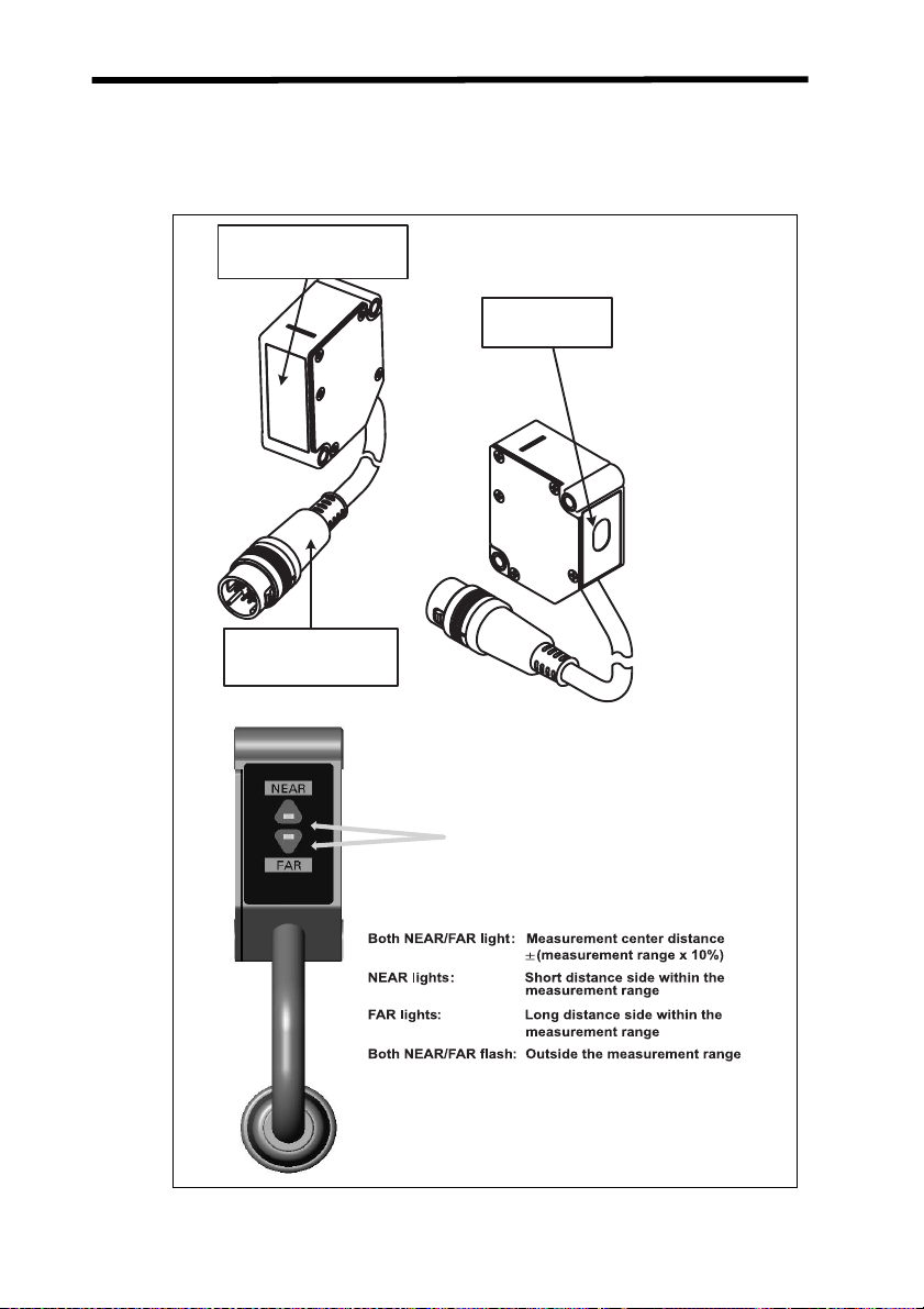
Names of Sensor Parts Section 1-1
1-1 Names of Sensor Parts
1-1-1 Reflective Sensor Heads
A Reflective Sensor Head is used for displacement measurements.
Emitter/receiver
(optical filter
Output cable
(with connector)
)
Display area
Range indicators
(green)
Range Indicator Lighting Status
2
Names of Sensor Parts Section 1-1
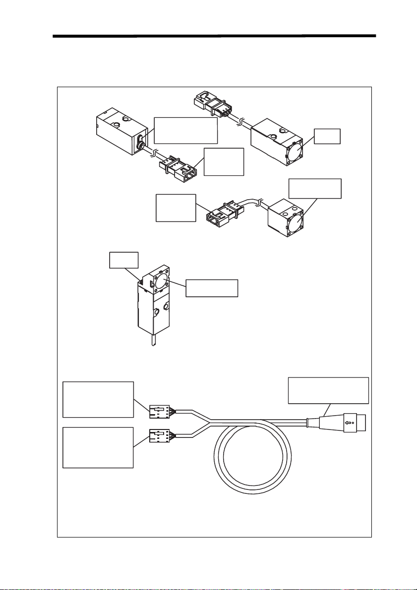
1-1-2 Through-beam Sensor Heads
A Through-beam Sensor Head is used for length measurements and consists of two main parts: An Emitter and a Receiver.
Emitter
Mounting
screw
Emitter-side Sensor
Head connector
Cable color: Gray
Laser ON indicator
(green)
Lit when light is emitted.
Emitter-side
Sensor Head
connector
Receiver-side
Sensor Head
connector
Side-view Attachment
Emitting/receiving
section
Sensor Head to Amplifier Unit
Connecting Cable (1.5 m)
Emitter
Receiver
Light
emitter
Light receiver
(optical filter)
Amplifier Unit
connector
Receiver-side
Sensor Head
connector
Cable color: Black
3
Names of Sensor Parts Section 1-1
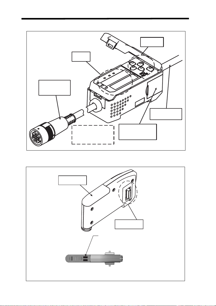
1-1-3 Amplifier Units
Controls
Display
area
Input cable
(with connector)
Output cable
The current/voltage switch
for the linear output is on the
bottom.
1-1-4 Calculating Unit
Display area
Connector
(Cover opens and closes.)
Connector
Connection Indicators:
Light when the Calculating Unit is
connected to Amplifier Units.
4
External Amplifier Unit I/O Section 1-2
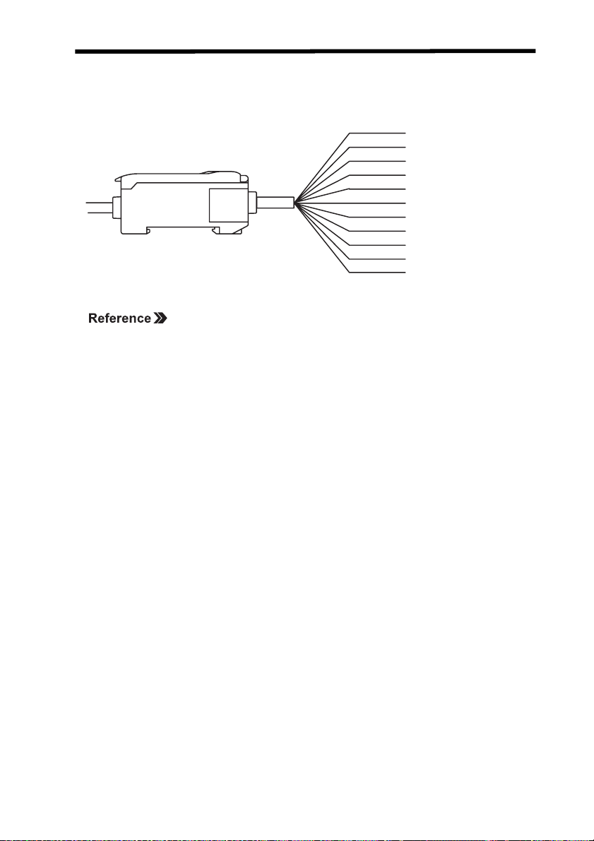
1-2 External Amplifier Unit I/O
The following functions are allocated to the external I/O lines.
Brown
Blue
White
Green
Gray
Black
Shield
Pink
Orange
Purple
Red
12 to 24 VDC
GND (0 V)
HIGH output
PASS output
LOW output
Linear output
Linear output GND
Laser OFF input
Zero reset input
Ti
ming input
Reset input
Refer to 3-2 Hardware Functions for I/O functions.
Note 1. Use a separate stabilized power supply for the Amplifier Unit, particu-
larly when high resolution is required.
2. Wire the Unit correctly. Incorrect wiring may result in damage to the
Unit. (Do not allow the I/O lines, particularly the linear output, to come
into contact with other lines.)
3. Use the 0-V ground line (blue line) for the power supply and use the
shield wire (linear output ground) together with the linear output (black
line) for linear output. Each of these grounds must be used for the
designed purpose. When not using the linear output, connect the linear output ground to the 0-V ground line.
5

I/O Circuit Diagrams Section 1-3
1-3 I/O Circuit Diagrams
1-3-1 NPN Amplifier Unit: ZX-LDA11
Brown
12 to 24 VDC
Load
Load
Load
12 to 24 VDC
Internal circuits
White
Green
Gray
Blue
Pink
Purple
Orange
Red
HIGH output
PASS output
LOW output
GND (0 V)
Laser OFF input
Timing input
Zero reset input
Reset input
Current/voltage
switch
100
Current output
Voltage output
4 to 20 mA
4 V
Shield
Black
Linear output GND
Linear output
Current output: 300 max.
Load
Voltage output: 10 min.k
6

I/O Circuit Diagrams Section 1-3
1-3-2 PNP Amplifier Unit: ZX-LDA41
Brown
12 to 24 VDC
Internal circuits
Current/voltage
output selector
100
Current output
4 to 20 mA
Voltage output
4 V
White
HIGH
PASS output
Green
Gray
LOW output
Blue
Pink
Purple
Orange
Red
Linear output
Black
Linear output GND
Shield
output
Load
GND (0 V)
Laser OFF input
ming input
Ti
Zero reset input
Reset input
12 to
24 VD
Load
Load
Current output: 300 max.
Load
Voltage output: 10 min.
C
k
7
Connections Section 1-4
1-4 Connections
1-4-1 Sensor Head and Amplifier Unit
1. Insert the output cable connector of the Sensor Head into the input cable connector of the Amplifier Unit until the connector ring
locks into place.
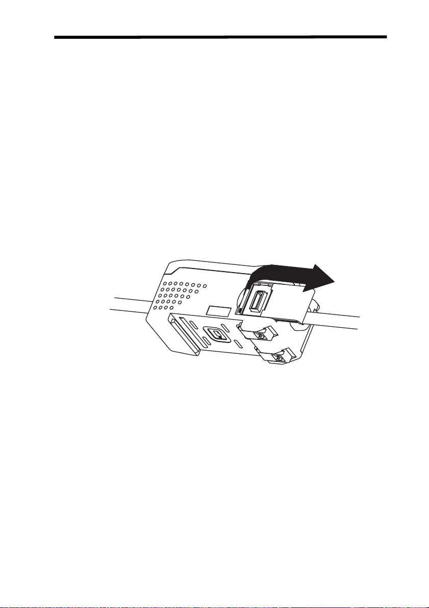
2. When disconnecting the Sensor Head, hold the connector ring
and Amplifier Unit connector and pull them straight out.
• Do not pull only on the connector ring, because the input cable of
the Amplifier Unit may be damaged.
• Do not touch the pins or contacts inside the connectors.
1-4-2 Connecting Cable and Sensor Head
This procedure is necessary for Through-beam Sensor Heads only.
1. Insert the emitter-side and receiver-side connectors from the
Sensor Head into both the emitter-side and receiver-side connectors on the Connecting Cable until they lock in place.
Connect the gray cables for the Emitter and the black cables for
the Receiver.
2. When disconnecting the Sensor Head, detach the emitter-side
and receiver-side connectors on the Connecting Cable from the
emitter-side and receiver-side connectors on the Sensor Head
cables and then pull them straight out.
• Do not touch the pins or contacts inside the connector.
• Never allow the connectors to be subjected to electrostatic
charges.
8
Connections Section 1-4
1-4-3 Extension Cables
When extending Sensor Head and Amplifier Unit cables, use the following
special cables (order separately).
• 1-m Cable: ZX-XC1A
• 4-m Cable: ZX-XC4A
• 8-m Cable: ZX-XC8A
• 9-m Cable: ZX-XC9A (for use with Reflective Sensors only)
Connect the Extension Cable between the Connecting Cable and the
Amplifier Unit.
Note: Never use two or more Extension Cables to extend the cable length.
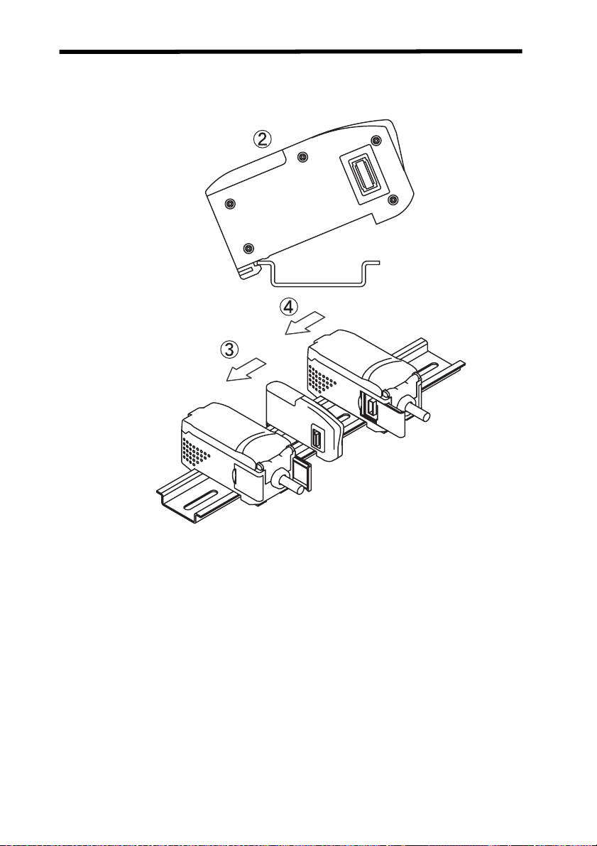
1-4-4 Amplifier Units and Calculating Unit
1. Open the connector covers on the Amplifier Units by lifting and
slide them open.
2. Mount the front section of the Calculating Unit to the DIN Track.
3. Slide the Calculating Unit on the DIN Track until the Calculating
Unit connector connects securely to the connector on the first
Amplifier Unit. The connectors should click into place.
9
Connections Section 1-4
4. Slide the other Amplifier Unit on the DIN Track until the Calculating Unit connector connects securely to the Amplifier Unit connector. The connectors should click into place.
Note 1. Connect the connectors only after mounting the Units to the DIN
Tr ac k .
2. Use an PFP-M End Plate when necessary to prevent the Amplifier
Units from moving (e.g., as a result of vibration).
10
 Loading...