

Omron ZX2-LDA41, ZX2-LD100L, ZX2-LD50V, ZX2-XC1R, ZX2-XC4R User Manual
...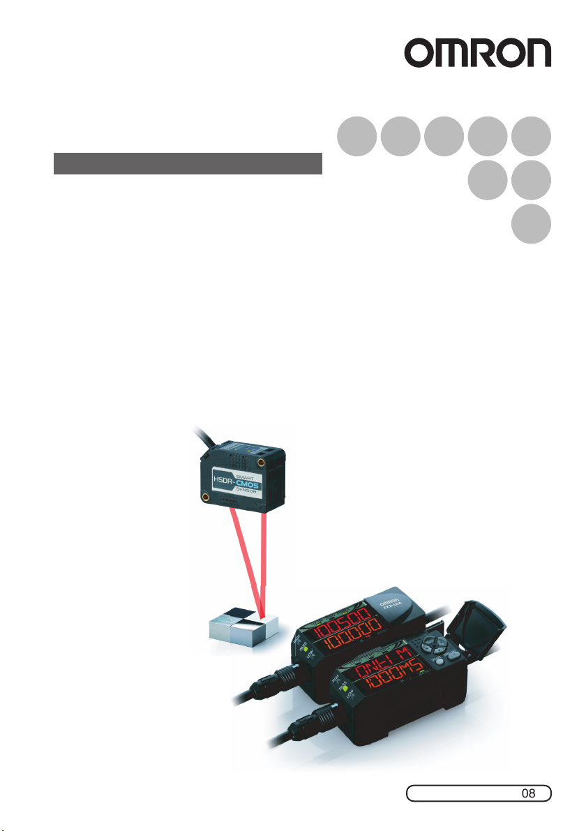
Smart Sensors
Laser Displacement Sensors CMOS Type
ZX2 Series
User’s Manual
Cat. No. Z310-E1-08

CONTENTS
INTRODUCTION
PREPARATION
FOR
MEASUREMENT
FLOW OF
OPERATION
BASIC
SETUP
MAIN
APPLICATIONS
& SETTING
METHODS
Height
Steps
and
Warpage
Double
Sheet
Detection
Thickness
Positioning
Eccentricity
and Surface
Deflection
DETAILED
SETTINGS
CONTENTS
Introduction
Meanings of Signal Words. . . . . . . . . . . . . . . . . . . . . . . . . . . . . . . . . . . . . . . . . . . 8
Meanings of Alert Symbols . . . . . . . . . . . . . . . . . . . . . . . . . . . . . . . . . . . . . . . . . . 8
Laser Safety . . . . . . . . . . . . . . . . . . . . . . . . . . . . . . . . . . . . . . . . . . . . . . . . . . . . . 9
Precautions for Safe Use. . . . . . . . . . . . . . . . . . . . . . . . . . . . . . . . . . . . . . . . . . . 11
Precautions for Correct Use . . . . . . . . . . . . . . . . . . . . . . . . . . . . . . . . . . . . . . . . 12
How to Use This Manual . . . . . . . . . . . . . . . . . . . . . . . . . . . . . . . . . . . . . . . . . . . 14
PREPARATION FOR MEASUREMENT
Part Names and Functions . . . . . . . . . . . . . . . . . . . . . . . . . . . . . . . . . . . . . . 18
Basic Configuration . . . . . . . . . . . . . . . . . . . . . . . . . . . . . . . . . . . . . . . . . . . . . . . 18
Amplifier Unit . . . . . . . . . . . . . . . . . . . . . . . . . . . . . . . . . . . . . . . . . . . . . . . . . . . . 19
Sensor Head . . . . . . . . . . . . . . . . . . . . . . . . . . . . . . . . . . . . . . . . . . . . . . . . . . . . 22
Calculating Unit . . . . . . . . . . . . . . . . . . . . . . . . . . . . . . . . . . . . . . . . . . . . . . . . . . 22
Installation. . . . . . . . . . . . . . . . . . . . . . . . . . . . . . . . . . . . . . . . . . . . . . . . . . . . 23
Installing Sensor Heads. . . . . . . . . . . . . . . . . . . . . . . . . . . . . . . . . . . . . . . . . . . . 23
Installing the Amplifier Unit . . . . . . . . . . . . . . . . . . . . . . . . . . . . . . . . . . . . . . . . . 25
Connecting Calculating Units . . . . . . . . . . . . . . . . . . . . . . . . . . . . . . . . . . . . . . . 26
Connecting the Sensor Head to the Amplifier Unit . . . . . . . . . . . . . . . . . . . . . . . 28
Wiring Diagram . . . . . . . . . . . . . . . . . . . . . . . . . . . . . . . . . . . . . . . . . . . . . . . . 30
Wiring Input/Output Cables . . . . . . . . . . . . . . . . . . . . . . . . . . . . . . . . . . . . . . . . . 30
I/O Circuit Diagrams . . . . . . . . . . . . . . . . . . . . . . . . . . . . . . . . . . . . . . . . . . . . . . 33
FLOW OF OPERATION
FLOW OF OPERATION. . . . . . . . . . . . . . . . . . . . . . . . . . . . . . . . . . . . . . . . . . 36
TROUBLESHOOTING
SPECIFICATIONS
INDEX
SETTING
TRANSITION
CHARTS
2
BASIC SETUP
BASIC SETUP . . . . . . . . . . . . . . . . . . . . . . . . . . . . . . . . . . . . . . . . . . . . . . . . . 40
Display of RUN Mode . . . . . . . . . . . . . . . . . . . . . . . . . . . . . . . . . . . . . . . . . . . . . 40
Simplest Setting. . . . . . . . . . . . . . . . . . . . . . . . . . . . . . . . . . . . . . . . . . . . . . . . . . 40
MAIN APPLICATIONS & SETTING METHODS
Height. . . . . . . . . . . . . . . . . . . . . . . . . . . . . . . . . . . . . . . . . . . . . . . . . . . . . . . . 42
Steps and Warpage . . . . . . . . . . . . . . . . . . . . . . . . . . . . . . . . . . . . . . . . . . . . 47
Double Sheet Detection . . . . . . . . . . . . . . . . . . . . . . . . . . . . . . . . . . . . . . . . . 52
Thickness . . . . . . . . . . . . . . . . . . . . . . . . . . . . . . . . . . . . . . . . . . . . . . . . . . . . 57
ZX2 User’s Manual

Positioning . . . . . . . . . . . . . . . . . . . . . . . . . . . . . . . . . . . . . . . . . . . . . . . . . . . 66
Eccentricity and Surface Deflection . . . . . . . . . . . . . . . . . . . . . . . . . . . . . . . 72
DETAILED SETTINGS
Smart Tuning. . . . . . . . . . . . . . . . . . . . . . . . . . . . . . . . . . . . . . . . . . . . . . . . . . 80
Selecting the Initial Sub-Display . . . . . . . . . . . . . . . . . . . . . . . . . . . . . . . . . . 84
Connecting Two or More Amplifier Units . . . . . . . . . . . . . . . . . . . . . . . . . . . 86
Mutual Interference Prevention. . . . . . . . . . . . . . . . . . . . . . . . . . . . . . . . . . . 88
Setting the Hysteresis . . . . . . . . . . . . . . . . . . . . . . . . . . . . . . . . . . . . . . . . . . 91
Setting the Hold Function . . . . . . . . . . . . . . . . . . . . . . . . . . . . . . . . . . . . . . . 93
Bank Setting . . . . . . . . . . . . . . . . . . . . . . . . . . . . . . . . . . . . . . . . . . . . . . . . . . 99
Zero Reset . . . . . . . . . . . . . . . . . . . . . . . . . . . . . . . . . . . . . . . . . . . . . . . . . . . 101
Scaling . . . . . . . . . . . . . . . . . . . . . . . . . . . . . . . . . . . . . . . . . . . . . . . . . . . . . . 105
Analog Output. . . . . . . . . . . . . . . . . . . . . . . . . . . . . . . . . . . . . . . . . . . . . . . . 109
Output for Non-measurement . . . . . . . . . . . . . . . . . . . . . . . . . . . . . . . . . . . 111
Timer . . . . . . . . . . . . . . . . . . . . . . . . . . . . . . . . . . . . . . . . . . . . . . . . . . . . . . . 114
Setting the Differential Function . . . . . . . . . . . . . . . . . . . . . . . . . . . . . . . . . 116
External Input for Bank, Timing Input, Reset Input. . . . . . . . . . . . . . . . . . 118
Setting the Detection Surface Selection. . . . . . . . . . . . . . . . . . . . . . . . . . . 120
Key Lock Function . . . . . . . . . . . . . . . . . . . . . . . . . . . . . . . . . . . . . . . . . . . . 122
Initializing Settings Data . . . . . . . . . . . . . . . . . . . . . . . . . . . . . . . . . . . . . . . 123
TROUBLESHOOTING
Troubleshooting . . . . . . . . . . . . . . . . . . . . . . . . . . . . . . . . . . . . . . . . . . . . . . 128
Error Messages. . . . . . . . . . . . . . . . . . . . . . . . . . . . . . . . . . . . . . . . . . . . . . . 130
Q&A . . . . . . . . . . . . . . . . . . . . . . . . . . . . . . . . . . . . . . . . . . . . . . . . . . . . . . . . 133
SPECIFICATIONS
Specifications and Dimensions. . . . . . . . . . . . . . . . . . . . . . . . . . . . . . . . . . 136
Amplifier Units . . . . . . . . . . . . . . . . . . . . . . . . . . . . . . . . . . . . . . . . . . . . . . . . . . 136
Sensor Heads . . . . . . . . . . . . . . . . . . . . . . . . . . . . . . . . . . . . . . . . . . . . . . . . . . 138
Sensor Head Extension Cables. . . . . . . . . . . . . . . . . . . . . . . . . . . . . . . . . . . . .142
Calculating Unit . . . . . . . . . . . . . . . . . . . . . . . . . . . . . . . . . . . . . . . . . . . . . . . . . 143
Timing Charts . . . . . . . . . . . . . . . . . . . . . . . . . . . . . . . . . . . . . . . . . . . . . . . . 144
Engineering Data (Reference Value). . . . . . . . . . . . . . . . . . . . . . . . . . . . . . 147
Angle Characteristic . . . . . . . . . . . . . . . . . . . . . . . . . . . . . . . . . . . . . . . . . . . . . 147
Linearity Characteristic for Different Materials. . . . . . . . . . . . . . . . . . . . . . . . . . 149
Beam Size . . . . . . . . . . . . . . . . . . . . . . . . . . . . . . . . . . . . . . . . . . . . . . . . . . . . . 150
Reference: Distance between two diffuse-reflective models that causes malfunc-
tion when mutual interference prevention is turned off . . . . . . . . . . . . . . . . . . . 151
CONTENTS
INTRODUCTION
PREPARATION
FOR
MEASUREMENT
FLOW OF
OPERATION
BASIC
SETUP
MAIN
APPLICATIONS
& SETTING
METHODS
Height
Steps
and
Warpage
Double
Sheet
Detection
Thickness
Positioning
Eccentricity
and Surface
Deflection
DETAILED
SETTINGS
TROUBLESHOOTING
SPECIFICATIONS
INDEX . . . . . . . . . . . . . . . . . . . . . . . . . . . . . . . . . . . . . . . . . . . . . . . . . . . . . 153
Revision History . . . . . . . . . . . . . . . . . . . . . . . . . . . . . . . . . . . . . . . . . . . . . . 157
SETTING TRANSITION CHARTS . . . . . . . . . . . . . . 158
ZX2 User’s Manual
INDEX
SETTING
TRANSITION
CHARTS
3

Introduction
CONTENTS
INTRODUCTION
PREPARATION
FOR
MEASUREMENT
FLOW OF
OPERATION
BASIC
SETUP
MAIN
APPLICATIONS
& SETTING
METHODS
Height
Steps
and
Warpage
Double
Sheet
Detection
Thickness
Positioning
Thank you for purchasing the ZX2 Series Smart Sensor. This manual provides
information regarding functions, performance and operating methods that are required for
using the sensor.
When using the ZX2 Smart Sensor, make sure to observe the following:
• The ZX2 Smart Sensor must be operated by personnel knowledgeable in electrical
engineering.
• To ensure correct use, please read this manual thoroughly to deepen your
understanding of the product.
• Please keep this manual in a safe place so that it can be referred to whenever
necessary.
Eccentricity
and Surface
Deflection
DETAILED
SETTINGS
TROUBLESHOOTING
SPECIFICATIONS
INDEX
SETTING
TRANSITION
CHARTS
4
ZX2 User’s Manual

Terms and Conditions Agreement
Warranty, Limitations of Liability
Warranties
Exclusive Warranty
Omron’s exclusive warranty is that the Products will be free from defects in materials and
workmanship for a period of twelve months from the date of sale by Omron (or such other
period expressed in writing by Omron). Omron disclaims all other warranties, express or
implied.
Limitations
OMRON MAKES NO WARRANTY OR REPRESENTATION, EXPRESS OR IMPLIED,
ABOUT NON-INFRINGEMENT, MERCHANTABILITY OR FITNESS FOR A
PARTICULAR PURPOSE OF THE PRODUCTS. BUYER ACKNOWLEDGES THAT IT
ALONE HAS DETERMINED THAT THE PRODUCTS WILL SUITABLY MEET THE
REQUIREMENTS OF THEIR INTENDED USE.
Omron further disclaims all warranties and responsibility of any type for claims or
expenses based on infringement by the Products or otherwise of any intellectual property
right.
Buyer Remedy
Omron's sole obligation hereunder shall be, at Omron's election, to (i) replace (in the form
originally shipped with Buyer responsible for labor charges for removal or replacement
thereof) the non-complying Product, (ii) repair the non-complying Product, or (iii) repay or
credit Buyer an amount equal to the purchase price of the non-complying Product;
provided that in no event shall Omron be responsible for warranty, repair, indemnity or
any other claims or expenses regarding the Products unless Omron's analysis confirms
that the Products were properly handled, stored, installed and maintained and not subject
to contamination, abuse, misuse or inappropriate modification. Return of any Products by
Buyer must be approved in writing by Omron before shipment. Omron Companies shall
not be liable for the suitability or unsuitability or the results from the use of Products in
combination with any electrical or electronic components, circuits, system assemblies or
any other materials or substances or environments. Any advice, recommendations or
information given orally or in writing, are not to be construed as an amendment or addition
to the above warranty.
See http://www.omron.com/global/ or contact your Omron representative for published
information.
CONTENTS
INTRODUCTION
PREPARATION
FOR
MEASUREMENT
FLOW OF
OPERATION
BASIC
SETUP
MAIN
APPLICATIONS
& SETTING
METHODS
Height
Steps
and
Warpage
Double
Sheet
Detection
Thickness
Positioning
Eccentricity
and Surface
Deflection
DETAILED
SETTINGS
TROUBLESHOOTING
SPECIFICATIONS
INDEX
ZX2 User’s Manual
SETTING
TRANSITION
CHARTS
5

Limitation on Liability; Etc
CONTENTS
INTRODUCTION
PREPARATION
FOR
MEASUREMENT
FLOW OF
OPERATION
BASIC
SETUP
MAIN
APPLICATIONS
& SETTING
METHODS
Height
Steps
and
Warpage
Double
Sheet
Detection
Thickness
Positioning
Eccentricity
and Surface
Deflection
OMRON COMPANIES SHALL NOT BE LIABLE FOR SPECIAL, INDIRECT,
INCIDENTAL, OR CONSEQUENTIAL DAMAGES, LOSS OF PROFITS OR
PRODUCTION OR COMMERCIAL LOSS IN ANY WAY CONNECTED WITH THE
PRODUCTS, WHETHER SUCH CLAIM IS BASED IN CONTRACT, WARRANTY,
NEGLIGENCE OR STRICT LIABILITY.
Further, in no event shall liability of Omron Companies exceed the individual price of the
Product on which liability is asserted.
Application Considerations
Suitability of Use
Omron Companies shall not be responsible for conformity with any standards, codes or
regulations which apply to the combination of the Product in the Buyer's application or
use of the Product. At Buyer's request, Omron will provide applicable third party
certification documents identifying ratings and limitations of use which apply to the
Product. This information by itself is not sufficient for a complete determination of the
suitability of the Product in combination with the end product, machine, system, or other
application or use. Buyer shall be solely responsible for determining appropriateness of
the particular Product with respect to Buyer's application, product or system. Buyer shall
take application responsibility in all cases.
NEVER USE THE PRODUCT FOR AN APPLICATION INVOLVING SERIOUS RISK TO
LIFE OR PROPERTY WITHOUT ENSURING THAT THE SYSTEM AS A WHOLE HAS
BEEN DESIGNED TO ADDRESS THE RISKS, AND THAT THE OMRON PRODUCT(S)
IS PROPERLY RATED AND INSTALLED FOR THE INTENDED USE WITHIN THE
OVERALL EQUIPMENT OR SYSTEM.
DETAILED
SETTINGS
TROUBLESHOOTING
SPECIFICATIONS
INDEX
SETTING
TRANSITION
CHARTS
6
Programmable Products
Omron Companies shall not be responsible for the user's programming of a
programmable Product, or any consequence thereof.
ZX2 User’s Manual

Disclaimers
Performance Data
Data presented in Omron Company websites, catalogs and other materials is provided as
a guide for the user in determining suitability and does not constitute a warranty. It may
represent the result of Omron's test conditions, and the user must correlate it to actual
application requirements. Actual performance is subject to the Omron's Warranty and
Limitations of Liability.
Change in Specifications
Product specifications and accessories may be changed at any time based on
improvements and other reasons. It is our practice to change part numbers when
published ratings or features are changed, or when significant construction changes are
made. However, some specifications of the Product may be changed without any notice.
When in doubt, special part numbers may be assigned to fix or establish key
specifications for your application. Please consult with your Omron's representative at
any time to confirm actual specifications of purchased Product.
Errors and Omissions
Information presented by Omron Companies has been checked and is believed to be
accurate; however, no responsibility is assumed for clerical, typographical or proofreading
errors or omissions.
CONTENTS
INTRODUCTION
PREPARATION
FOR
MEASUREMENT
FLOW OF
OPERATION
BASIC
SETUP
MAIN
APPLICATIONS
& SETTING
METHODS
Height
Steps
and
Warpage
Double
Sheet
Detection
Thickness
Positioning
ZX2 User’s Manual
Eccentricity
and Surface
Deflection
DETAILED
SETTINGS
TROUBLESHOOTING
SPECIFICATIONS
INDEX
SETTING
TRANSITION
CHARTS
7
CONTENTS
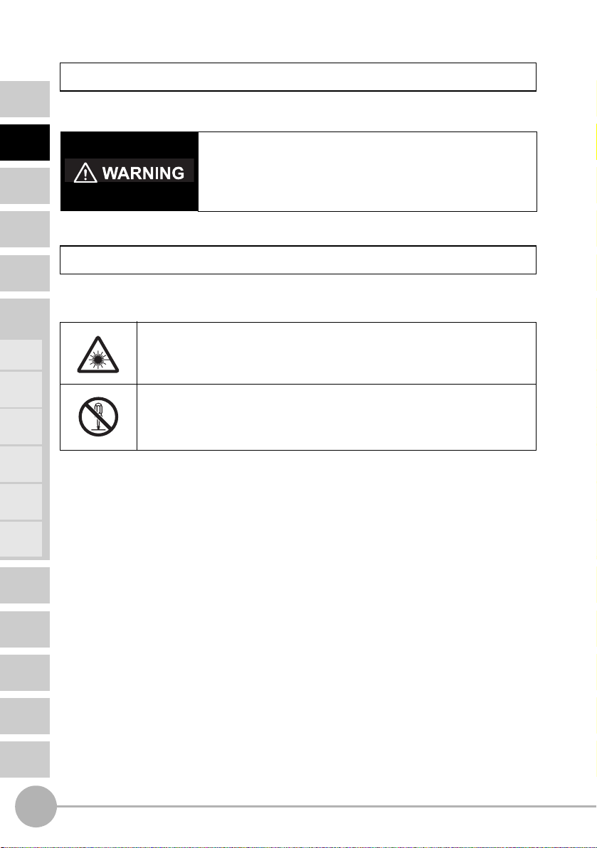
Meanings of Signal Words
The following signal words are used in this manual.
INTRODUCTION
PREPARATION
FOR
MEASUREMENT
FLOW OF
OPERATION
BASIC
SETUP
MAIN
APPLICATIONS
& SETTING
METHODS
Height
Steps
and
Warpage
Double
Sheet
Detection
Thickness
Positioning
Eccentricity
and Surface
Deflection
Indicates a potentially hazardous situation which, if not
avoided, will result in minor or moderate injury, or may result in
serious injury or death. Additionally there may be significant
property damage.
Meanings of Alert Symbols
The following alert symbols are used in this manual.
Indicates the possibility of laser radiation.
Indicates prohibition when there is a risk of minor injury from electrical
shock or other source if the product is disassembled.
DETAILED
SETTINGS
TROUBLESHOOTING
SPECIFICATIONS
INDEX
SETTING
TRANSITION
CHARTS
8
ZX2 User’s Manual
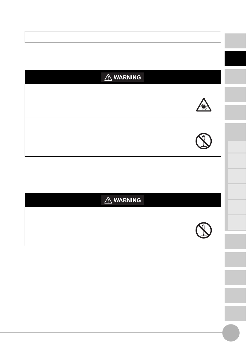
Laser Safety
Sensor Head
ZX2-LD50L, LD50, LD100L, LD100: Class 2
CONTENTS
INTRODUCTION
Never look into the laser beam.
Doing so continuously will result in visual impairment.
Do not disassemble the product.
Doing so may cause the laser beam to leak, resulting in the danger of
visual impairment.
Sensor Head
ZX2-LD50V: Class 1
Do not disassemble the product.
Doing so may cause the laser beam to leak, resulting in the danger of
visual impairment.
PREPARATION
FOR
MEASUREMENT
FLOW OF
OPERATION
BASIC
SETUP
MAIN
APPLICATIONS
& SETTING
METHODS
Height
Steps
and
Warpage
Double
Sheet
Detection
Thickness
Positioning
Eccentricity
and Surface
Deflection
DETAILED
SETTINGS
ZX2 User’s Manual
TROUBLESHOOTING
SPECIFICATIONS
INDEX
SETTING
TRANSITION
CHARTS
9

CONTENTS
INTRODUCTION
PREPARATION
FOR
MEASUREMENT
FLOW OF
OPERATION
BASIC
SETUP
MAIN
APPLICATIONS
& SETTING
METHODS
Height
Steps
and
Warpage
Double
Sheet
Detection
Thickness
Positioning
Eccentricity
and Surface
Deflection
DETAILED
SETTINGS
TROUBLESHOOTING
In Europe, diffuse-reflective models in the ZX2 Series are categorized as Class 2 laser
products and the regular-reflective model is classified as a Class 1 laser product
according to EN60825-1 (see note).
The CE markings on the products also reflect these categorizations.
In the U.S.A., diffuse-reflective models in the ZX2 Series are categorized as Class II laser
products, and the regular-reflective model is classified as a Class I laser product
according to IEC60825-1 criteria, in accordance with the stipulations of the FDA standard
Laser Notice No. 50 (see note).
This product has already been registered with the CDRH (Center for Devices and
Radiological Health). (Accession Number: 1020665)
Place the laser warning label and the FDA label on the sensor.
The ZX2 Series is meant to be built into final system equipment. Pay special attention to
the following precautions for the safe use of the product:
Note: Europe: Class 1 and Class 2 of EN 60825-1: 1994 +A11:1996 +A2:2001
= IEC 60825-1:1993 +A1:1997 +A2:2001
U.S.A.: Class I and Class II of FDA (21 CFR1040.10)
(1) ZX2-LD emits visual laser beam. Do not stare directly into the laser.
Make sure that the laser beam path is terminated. If specular objects are present in
the laser beam path, make sure that they are prevented from reflecting the laser
beam.
When used without an enclosure, make sure the laser path from eye level is avoided.
(2) To avoid exposure to hazardous laser radiation, do not displace nor remove the
protective housing during operation, maintenance, and any other servicing.
(3) As for countries other than those of Europe and the U.S.A., observe the regulations
and standards specified by each country.
(4) Label Indications
The EN and FDA labels are supplied with the product.
Replace the current labels with them according to the instructions given in the
manuals.
SPECIFICATIONS
INDEX
SETTING
TRANSITION
CHARTS
10
ZX2 User’s Manual
Precautions for Safe Use
Please observe the following precautions for safe use of the products.
Installation Environment
• Do not use the product in environments where it can be exposed to inflammable/
explosive gas.
• Do not install the product close to high-voltage devices and power devices in order
to secure the safety of operation and maintenance.
Power Supply and Wiring
• The supply voltage must be within the rated range (DC12 to 24 V±10%).
• Reverse connection of power supply is not allowed. Connection to AC power supply
is also not allowed.
• Open-collector outputs should not be short-circuited.
• High-voltage lines and power lines must be wired separately from this product.
Wiring them together or placing in the same duct may cause induction, resulting in
malfunction or damage.
• Always turn off the power supply before connecting or disconnecting cables and
connectors.
Applicable standards
• EN61326-1
• Electromagnetic environment : Industrial electromagnetic environment
(EN/IEC 61326-1 Table 2)
• There may be cases that current output or voltage output fluctuate within 1%F.S
when a sensor is experienced electromagnetic interference under the condition of
the response time 30µs.
Others
• Do not attempt to dismantle, repair, or modify the product.
• Dispose of this product as industrial waste.
CONTENTS
INTRODUCTION
PREPARATION
FOR
MEASUREMENT
FLOW OF
OPERATION
BASIC
SETUP
MAIN
APPLICATIONS
& SETTING
METHODS
Height
Steps
and
Warpage
Double
Sheet
Detection
Thickness
Positioning
Eccentricity
and Surface
Deflection
DETAILED
SETTINGS
TROUBLESHOOTING
SPECIFICATIONS
ZX2 User’s Manual
INDEX
SETTING
TRANSITION
CHARTS
11
CONTENTS
INTRODUCTION
PREPARATION
FOR
MEASUREMENT
FLOW OF
OPERATION
BASIC
SETUP
MAIN
APPLICATIONS
& SETTING
METHODS
Height
Steps
and
Warpage
Double
Sheet
Detection
Thickness
Positioning
Eccentricity
and Surface
Deflection
DETAILED
SETTINGS
TROUBLESHOOTING
SPECIFICATIONS
INDEX
SETTING
TRANSITION
CHARTS
Precautions for Correct Use
Please observe the following precautions to prevent failure to operate, malfunctions, or
Please observe the following precautions to prevent failure to operate, malfunctions, or
undesirable effects on product performance.
undesirable effects on product performance.
Installation of the Product
Installation of the Product
Installation Site
Installation Site
Do not install the product in locations subjected to the following conditions:
Do not install the product in locations subjected to the following conditions:
• Ambient temperature outside the rating
• Ambient temperature outside the rating
• Rapid temperature fluctuations (causing condensation)
• Rapid temperature fluctuations (causing condensation)
• Relative humidity outside the range of 35 to 85%
• Relative humidity outside the range of 35 to 85%
• Presence of corrosive or flammable gases
• Presence of corrosive or flammable gases
• Presence of dust, salt, or iron particles
• Presence of dust, salt, or iron particles
• Direct vibration or shock
• Direct vibration or shock
• Reflective sensor of intense light (such as other laser beams or electric arc-welding
• Reflective sensor of intense light (such as other laser beams or electric arc-welding
machines)
machines)
• Direct sunlight or near heaters
• Direct sunlight or near heaters
• Water, oil, or chemical fumes or spray
• Water, oil, or chemical fumes or spray
• Strong magnetic or electric field
• Strong magnetic or electric field
Component Installation and Handling
Component Installation and Handling
Power Supply and Wiring
Power Supply and Wiring
• To extend the output cables of amplifier units, shielded cables of the same specifi-
• When using a commercially available switching regulator, make sure that the FG
cations as the output cables must be used.
terminal is grounded.
• When using a commercially available switching regulator, make sure that the FG
• If surge currents are present in the power lines, connect surge absorbers that suit
terminal is grounded.
the operating environment.
• If surge currents are present in the power lines, connect surge absorbers that suit
• When connecting two or more amplifier units by using calculating units, make sure
the operating environment.
that the linear GND lines of the amplifier units are connected to each other. Supply
• When using two or more amplifier units or calculating units, make sure that the lin-
power to all connected amplifier units at the same time.
ear GND line of the amplifier units are connected to each other.
• Before turning ON the power after the product is connected, make sure that the
• Before turning ON the power after the product is connected, make sure that the
power supply voltage is correct, there are no incorrect connections (e.g. load short-
power supply voltage is correct, there are no incorrect connections (e.g. load short-
circuit) and the load current is appropriate. Incorrect wiring may result in breakdown
circuit) and the load current is appropriate. Incorrect wiring may result in breakdown
of the product.
of the product.
• The ferrite core accessory must be attached to the sensor head cable before use.
• The cables must be 10 m or shorter in total length, for both sensor head and ampli-
(For how to attach the ferrite core, see pages 24 and 28.)
fier units. To extend the cable from the sensor head, an optional extension cable
• The cables must be 10 m or shorter in total length for amplifier units. For extension
(ZX2-XCR) must be used. For extension of the cable of amplifier units, shielded
of the cable of amplifier units, shielded cables of the same type must be used. To
cables of the same type must be used.
extend the cable from the sensor head, an optional extension cable (ZX2-XCR)
• When using calculating units, make sure that the linear GND lines of the amplifier
must be used. Only one extension cable can be used.
units are connected to each other.
• When using calculating units, make sure that the linear GND lines of the amplifier
units are connected to each other.
12
ZX2 User’s Manual

Warming Up
After turning ON the power supply, allow the product to stand for at least 10 minutes
before use. The circuits are still unstable just after the power supply is turned ON, so
measured values may fluctuate gradually.
A warmup of at least 10 minutes is also required after canceling LD-OFF input if LD-
OFF input is being used.
Sensing Object
The product cannot accurately measure the following types of objects: Transparent
objects, objects with an extremely low reflective sensor ratio, objects smaller than the
beam size, objects with a large curvature, excessively inclined objects, etc.
Mutual Interference
Inserting a calculating unit between amplifier units can prevent mutual interference
between two sensor heads.
Maintenance
• Always turn OFF the power supply before adjusting or connecting/disconnecting
the sensor head.
• Do not use thinner, benzene, acetone or kerosene to clean the sensor head and
amplifier units. If large dust particles adhere to the front filter of the sensor head,
use a blower brush (used to clean camera lenses) to blow them off. Do not blow the
dust away with your mouth. To remove smaller dust particles, use a soft cloth (for
lenses) with a small amount of alcohol. Take care not to wipe them off with exces-
sive force.
Scratches on the filter may cause errors.
CONTENTS
INTRODUCTION
PREPARATION
FOR
MEASUREMENT
FLOW OF
OPERATION
BASIC
SETUP
MAIN
APPLICATIONS
& SETTING
METHODS
Height
Steps
and
Warpage
Double
Sheet
Detection
Thickness
Positioning
Eccentricity
and Surface
Deflection
ZX2 User’s Manual
DETAILED
SETTINGS
TROUBLESHOOTING
SPECIFICATIONS
INDEX
SETTING
TRANSITION
CHARTS
13
How to Use This Manual
g
CONTENTS
INTRODUCTION
PREPARATION
FOR
MEASUREMENT
FLOW OF
OPERATION
BASIC
SETUP
MAIN
APPLICATIONS
& SETTING
METHODS
Height
Steps
and
Warpage
Double
Sheet
Detection
Thickness
Positioning
Eccentricity
and Surface
Deflection
DETAILED
SETTINGS
TROUBLESHOOTING
SPECIFICATIONS
INDEX
SETTING
TRANSITION
CHARTS
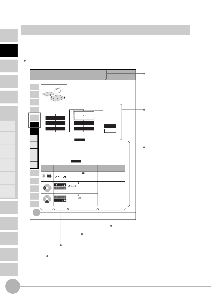
Page Format
This section explains the page format by using the Setting for MAIN APPLICATIONS AND
SETTING METHODS chapter as an example.
Index label
Shows the chapter and header titles with white characters.
Height
CONTENTS
INTRODUCTION
PREPARATION
FOR
MEASUREMENT
Procedure for setting up height
FLOW OF
OPERATION
BASIC
SETUP
MAIN
APPLICATIONS
& SETTING
METHODS
Height
Steps
and
Warpage
Double
Sheet
Detection
Thickness
Positioning
Eccentricity
and Surface
Deflection
DETAILED
SETTINGS
TROUBLESHOOTING
SPECIFICATIONS
INDEX
SETTING
TRANSITION
CHARTS
Sensor installation/wiring
1
Set to the MENU mode
2
Response time setting
3
4
1 Sensor installation/wiring
Has the Sensor been installed and wired? (See page 23.)
Set the reference workpiece in place, adjust the position of the Sensor Head while
looking at the digital display values on the Amplifier Unit or the indicators on the
Sensor Head so that the height to be measured is near the measurement center
distance, and install the Sensor Head at this position.
2 Set to the MENU mode
Button
Operation
Hold down for
3 seconds
Press to display.
Press to display.
42
Height
Hold
5
Trigger conditions
6
Threshold setting
7
8
Smart tuning
Display Description of Operation
Button Operation
Shows how to use the buttons.
Return to RUN mode
Settin
Required
Required
Hold down the button for
Lit
three seconds to switch to the
MENU mode.
Press the button to display .* This operation is not
Press the button to set the
display to to set display of
the detail menu.
Display
Shows what is displayed as a result of the operation.
Other than
OFF
completed
Select the desired mode to set
the measurement conditions in.
required when hold and
trigger conditions are not to
be set.
Description of Operation
Explains how to perform the operation by using buttons.
Required setting
Optional setting
Explanation of
Selection Menu
ZX2 User’s Manual
Explanation of Selection Menu
Provides a supplemental explanation of the selection menu.
Header
Indicates the measurement
contents.
Flow
Shows the flow of operation.
Operation procedure
Explains the operation
procedure.
14
ZX2 User’s Manual

Meanings of Symbols
Symbol Meaning
Important
(For details about xxx,
see page xx.)
Required
(white characters on a black
background)
Optional
(black characters on a white
background)
Press to display.
Menu name
Menu name
Press to select
Select the
desired value.
[Change numeric value]
[Move digit]
Press to set.
Set any value.
Indicates points that are important to achieve the full product
performance, such as operational precautions and application procedures.
Indicates pages where related information can be found.
Indicates a required setting in a setup procedure.
Indicates an optional setting in a setup procedure.
Indicates which button to press to display the menu shown in
the Display column.
Indicates that the user can select the menu that accords with
their usage conditions by pressing the relevant button.
Indicates that the user can specify a value that accords with
their usage conditions by pressing the relevant button.
CONTENTS
INTRODUCTION
PREPARATION
FOR
MEASUREMENT
FLOW OF
OPERATION
BASIC
SETUP
MAIN
APPLICATIONS
& SETTING
METHODS
Height
Steps
and
Warpage
Double
Sheet
Detection
Thickness
Positioning
ZX2 User’s Manual
Eccentricity
and Surface
Deflection
DETAILED
SETTINGS
TROUBLESHOOTING
SPECIFICATIONS
INDEX
SETTING
TRANSITION
CHARTS
15

CONTENTS
INTRODUCTION
PREPARATION
FOR
MEASUREMENT
FLOW OF
OPERATION
BASIC
SETUP
MAIN
APPLICATIONS
& SETTING
METHODS
Height
Steps
and
Warpage
Double
Sheet
Detection
MEMO
Thickness
Positioning
Eccentricity
and Surface
Deflection
DETAILED
SETTINGS
TROUBLESHOOTING
SPECIFICATIONS
INDEX
SETTING
TRANSITION
CHARTS
16
ZX2 User’s Manual

1
PREPARATION FOR
MEASUREMENT
Part Names and Functions 18
Installation 23
Wiring Diagram 30
PREPARATION FOR MEASUREMENT
Part Names and Functions
y
CONTENTS
INTRODUCTION
PREPARATION
FOR
MEASUREMENT
FLOW OF
OPERATION
BASIC
SETUP
MAIN
APPLICATIONS
& SETTING
METHODS
Height
Steps
and
Warpage
Double
Sheet
Detection
Thickness
Positioning
Eccentricity
and Surface
Deflection
Basic Configuration
The basic configuration of the ZX2 series Smart Sensors is shown below.
(used for connecting two or more Amplifier Units)
(used for extending cable length)
Sensor Head
See the following pages for details:
Sensor Heads p. 22 p. 138
Amplifier Units p. 19 p. 136
Calculating Unit p. 22 p. 143
Extension Cables — p. 142
Calculating Unit
Extension Cable
*
* Only one extension cable can be used.
Amplifier Unit
Part Names and Functions Specifications and Dimensions
Power Suppl
(sold separately)
DETAILED
SETTINGS
TROUBLESHOOTING
SPECIFICATIONS
INDEX
SETTING
TRANSITION
CHARTS
18
Part Names and Functions
ZX2 User’s Manual
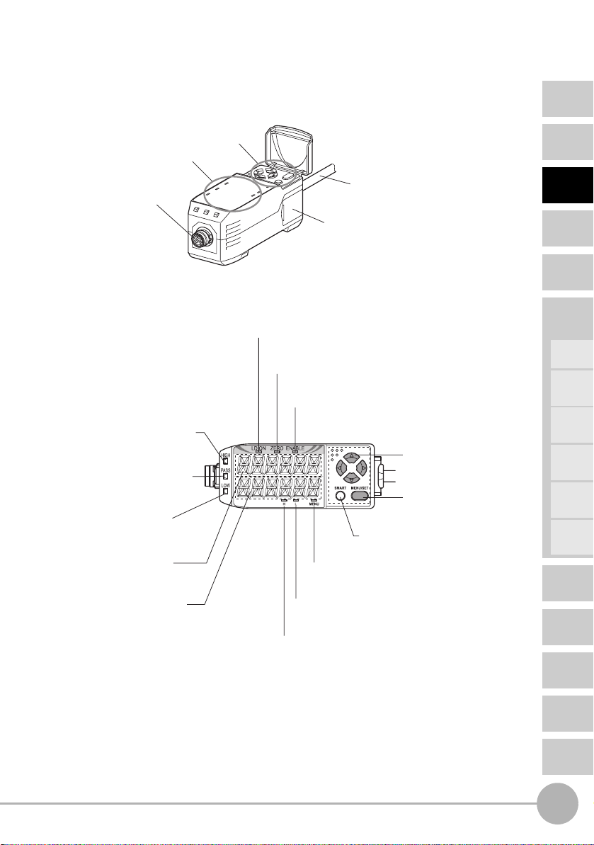
Amplifier Unit
CONTENTS
Operating Section (*)
Display section (*)
Sensor Head connector
This connector is for connecting
the Sensor Head.
(*) Operating and Display Sections
Laser ON indicator (green)
This indicator lights while the Sensor Head
is emitting a laser beam.
Zero reset indicator (green)
This indicator lights when the zero reset function is enabled.
HIGH indicator (orange)
This indicator lights when the
judgement result is HIGH.
PASS indicator (green)
This indicator lights when the
judgement result is PASS.
LOW indicator (orange)
This indicator lights when the
judgement result is LOW.
Main display (red)
This display shows measured
values and function names.
Sub-display (orange)
This display shows additional
information and function
settings for measurements.
HIGH threshold indicator (orange)
Output Cable
This cable is for connecting the power supply
and sync sensors or external devices.
Connector (two connectors, one on each side)
This connector is for connecting Calculating Units.
ENABLE indicator (green)
This indicator lights while the Sensor is ready for measurement. It goes out
when measurement is not possible (e.g. when the received light amount is
excessive or insufficient, when the measurement range is exceeded, or
when the Sensor Head is not connected when the power is turned ON).
Cursor buttons
These buttons are used for
switching the display and setting
measurement conditions.
MENU/SET button
This button is used for switching
the mode and finalizing settings.
Smart tuning button
This is used for setting optimum sensing
conditions according to the operating conditions.
MENU indicator (green)
This indicator lights in the MENU mode.
It goes out in the RUN mode.
LOW threshold indicator (orange)
This indicator lights when the LOW threshold is displayed
on the sub-display.
This indicator lights when the HIGH threshold is displayed
on the sub-display.
INTRODUCTION
PREPARATION
FOR
MEASUREMENT
FLOW OF
OPERATION
BASIC
SETUP
MAIN
APPLICATIONS
& SETTING
METHODS
Height
Steps
and
Warpage
Double
Sheet
Detection
Thickness
Positioning
Eccentricity
and Surface
Deflection
DETAILED
SETTINGS
TROUBLESHOOTING
SPECIFICATIONS
ZX2 User’s Manual
Part Names and Functions
INDEX
SETTING
TRANSITION
CHARTS
19
CONTENTS
INTRODUCTION
PREPARATION
FOR
MEASUREMENT
FLOW OF
OPERATION
BASIC
SETUP
MAIN
APPLICATIONS
& SETTING
METHODS
Height
Steps
and
Warpage
Double
Sheet
Detection
Digital Displays
The information displayed on the main and sub-displays depends on the currently
selected mode. The default mode is the RUN mode.
When the power is turned ON, the model of Amplifier Unit (ZX2-LDA) will be displayed on
the main display and the channel number will be displayed on the sub-display.
Subsequently, the Sensor Head software version will be displayed on the main display
and the Amplifier Unit software version will be displayed on the sub-display.
These details are displayed for approximately five seconds, and then data for the RUN
mode will be displayed.
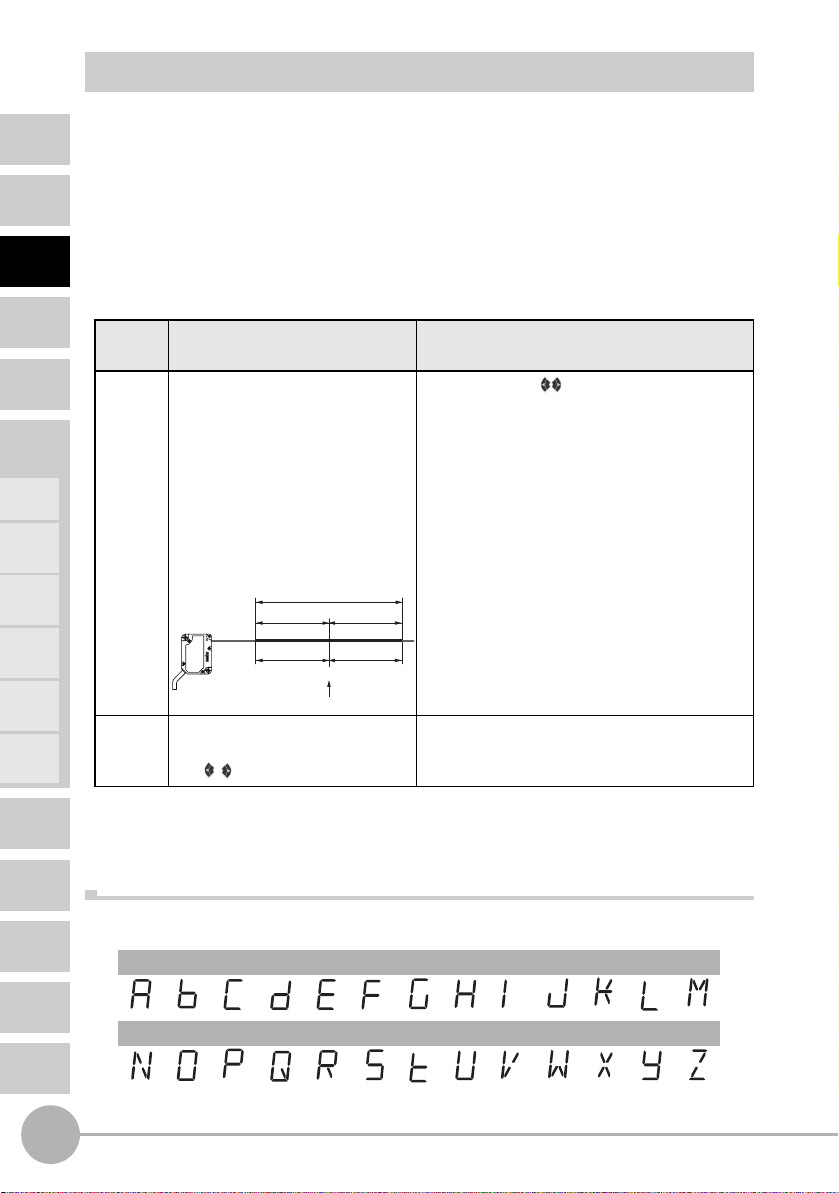
Mode Main display
(upper section, red)
RUN The measured value (the value
after the measurement conditions
have been reflected) is displayed.
For example, when the hold
function is set, the held value will
be displayed.
Default measured values are as
follows:
Measurement range
NEAR side FAR side
By pressing the button, the HIGH
threshold, LOW threshold, analog output
value, resolution (max. value of measured
value during one second - min. value), current
value (value before execution of zero reset,
hold, scaling and 2-sensor operation), and
BANK are displayed in this order.
Sub-display
(lower section, orange)
Thickness
Positioning
Eccentricity
and Surface
Deflection
DETAILED
SETTINGS
TROUBLESHOOTING
SPECIFICATIONS
INDEX
SETTING
TRANSITION
CHARTS
20
+ indication
Measurement center distance
MENU The function names are
displayed in order by pressing
- indication
0
The setting for the function displayed on the
main display is displayed.
the buttons.
(For details on setting transition charts, see page 158.)
Alphabet Display Format
The alphabet appears on the main and sub-displays as shown in the following table.
A B C D E F G H I J K L M
N O P Q R S T U V W X Y Z
Part Names and Functions
ZX2 User’s Manual
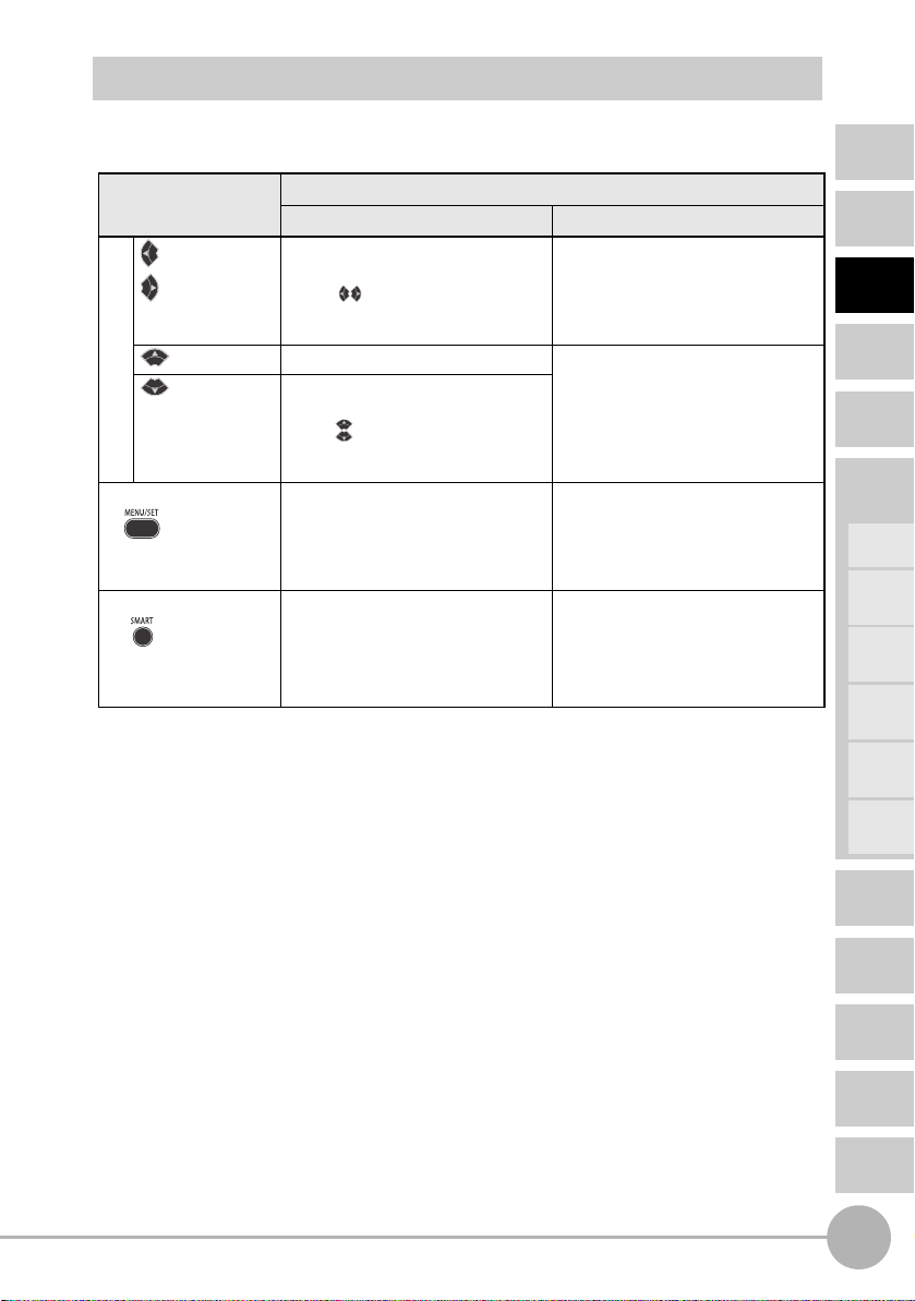
Button Operation
The functions of buttons change according to the currently selected mode.
Button type Button function
RUN mode MENU mode
button
button
button • Normal press: Executes timing input. The function changes depending on
button • Held down for one second:
Cursor buttons
MENU/SET button • Held down for 3 seconds:
Smart tuning button • Held down for one second, held
• Normal press:
Changes the sub-display content.*
• Both buttons held down for
three seconds:
Locks button operation.
Executes zero reset.
• Both buttons held down for one
second:
Cancels a zero reset.
Changes the mode to the MENU
mode.
down for three seconds, held down
for five seconds:
Executes smart tuning according
to the time the button is held
down.
* For how to select the initial sub-display to be displayed when the power is turned on, see
page 84.
Function changes depending on the
setting.
• Switches the function display.
• Selects the digit of numerical values.
• Stops setting.
the setting.
• Changes the selection menu.
• Changes numerical values.
• Normal press:
Finalizes the set condition or
value.
• Held down for 3 seconds:
Changes to the RUN mode.
• Held down for one second, held
down for three seconds, held down
for five seconds:
Executes smart tuning according
to the time the button is held
down.
CONTENTS
INTRODUCTION
PREPARATION
FOR
MEASUREMENT
FLOW OF
OPERATION
BASIC
SETUP
MAIN
APPLICATIONS
& SETTING
METHODS
Height
Steps
and
Warpage
Double
Sheet
Detection
Thickness
Positioning
ZX2 User’s Manual
Part Names and Functions
Eccentricity
and Surface
Deflection
DETAILED
SETTINGS
TROUBLESHOOTING
SPECIFICATIONS
INDEX
SETTING
TRANSITION
CHARTS
21
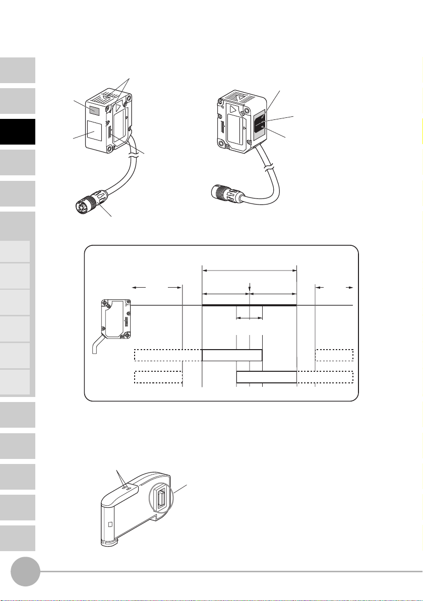
Sensor Head
CONTENTS
INTRODUCTION
PREPARATION
FOR
MEASUREMENT
FLOW OF
OPERATION
BASIC
SETUP
MAIN
APPLICATIONS
& SETTING
METHODS
Height
Steps
and
Warpage
Double
Sheet
Detection
Thickness
Positioning
Eccentricity
and Surface
Deflection
Emitting
section
Receiving
section
Emission center position mark
This mark indicates the emission center
position.
FAR
NEAR
CMOS position mark
This mark indicates the position of the
CMOS light-receiving element.
Connector
This is connected to the Amplifier Unit.
Indicator Operation According to Position of Workpiece
Measurement range
Measurement center distance
NEAR side
Measurement center distance
± (measurement range x 10%)
FAR side
(outside measurement
range)
NEAR
indicator
FAR
indicator
Error
Flashing FlashingLit
Flashing FlashingLit
FAR Indicator (green)
See the table below.
Laser life indicator (red)
NEAR Indicator (green)
See the table below.
Error
(outside measurement
range)
DETAILED
SETTINGS
TROUBLESHOOTING
SPECIFICATIONS
INDEX
SETTING
TRANSITION
CHARTS
22
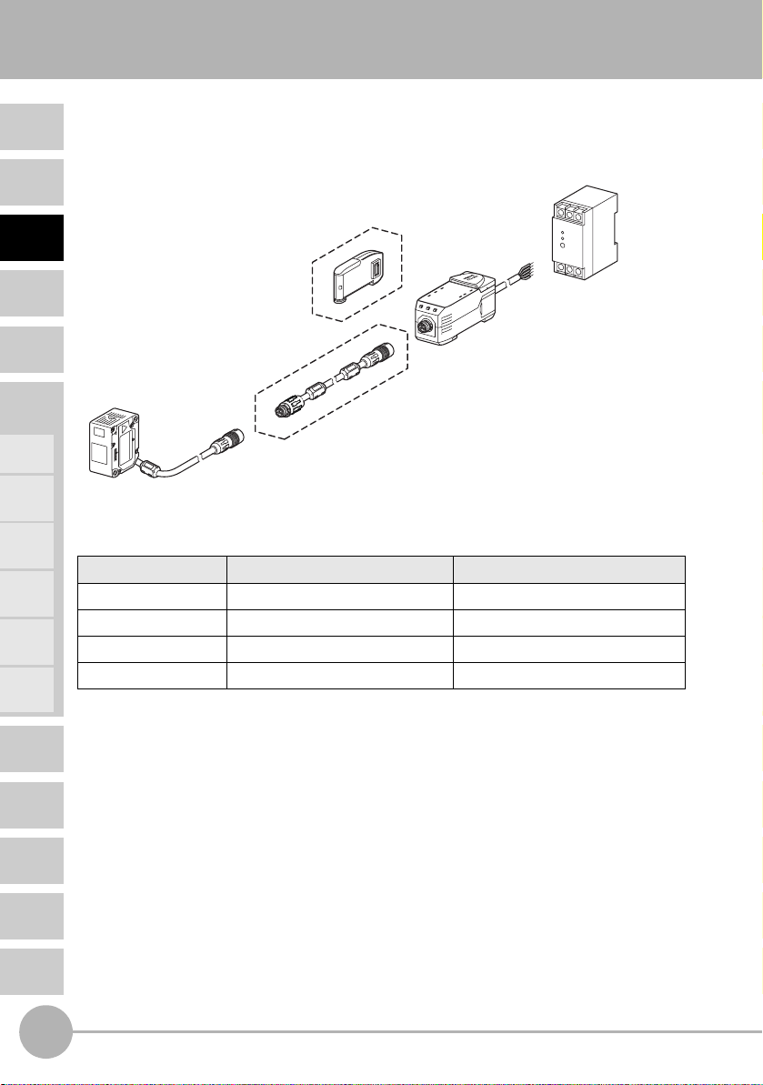
Calculating Unit
Connection indicator
This indicator lights when the
Amplifier Unit is connected.
Part Names and Functions
(used for connecting two or more Amplifier Units)
Connector (two connectors, one on each side)
This is connected to the Amplifier Unit.
ZX2 User’s Manual
Installation
5
Important
Before connecting/disconnecting Smart Sensor components, make sure that the power to the
Amplifier Unit is turned OFF. The Smart Sensor may malfunction if components are connected
or removed while the power is ON.
CONTENTS
INTRODUCTION
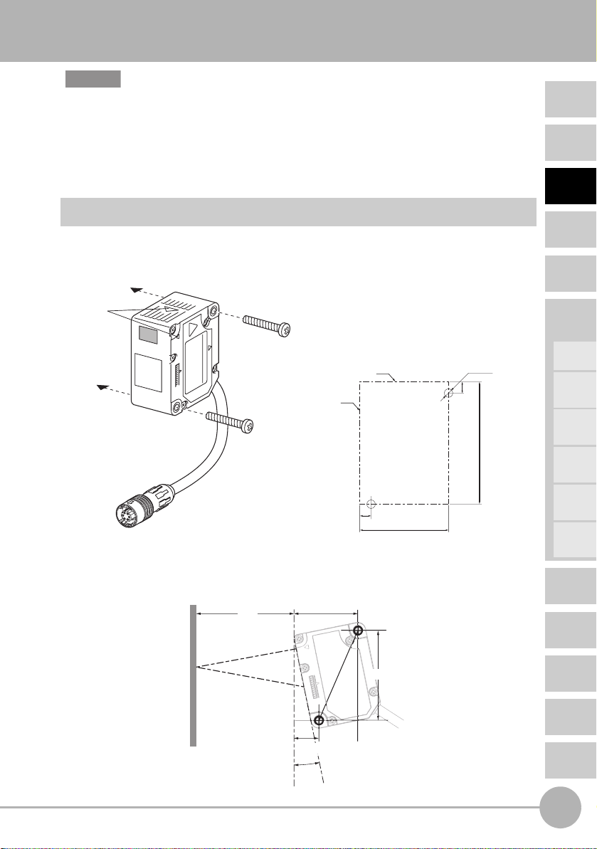
Installing Sensor Heads
Installation Method
• Check the Sensor Head setting position by its emission center mark.
• Fix the sensor head in place with M3 screws. The screws must be tightened with a
torque of 0.5 N•m.
Emission
center position
mark
Mounting dimensional drawing
(unit: mm)
Mounting reference
Mounting reference
4 ±0.05
31.5 ±0.05
• Tilt the regular-reflective model as shown below with respect to the workpiece.
A mounting bracket can also be attached to the regular-reflective model to tilt it
correctly. (E39-L178; see page 141.)
ZX2-LD50V
48
(Measurement center
distance)
31.4
±
0.05
2-M3
0.05
±
4
0.05
±
43.5
PREPARATION
FOR
MEASUREMENT
FLOW OF
OPERATION
BASIC
SETUP
MAIN
APPLICATIONS
& SETTING
METHODS
Height
Steps
and
Warpage
Double
Sheet
Detection
Thickness
Positioning
Eccentricity
and Surface
Deflection
DETAILED
SETTINGS
TROUBLESHOOTING
ZX2 User’s Manual
Workpiece
12.3 ±0.05
10.5°
44.1 ±0.0
Installation
SPECIFICATIONS
INDEX
SETTING
TRANSITION
CHARTS
23
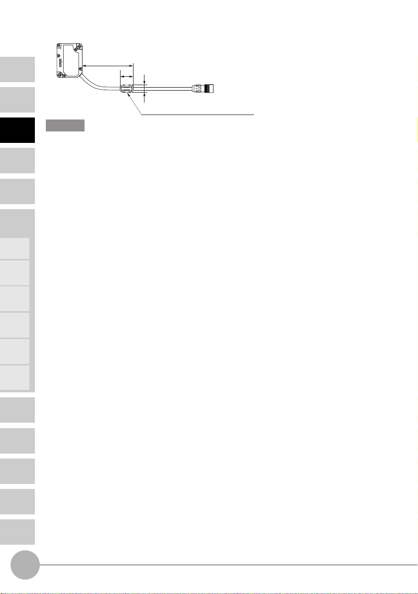
• Be sure to attach the ferrite core accessory to the Sensor Head. Attach it within
100 mm of the Sensor Head side.
CONTENTS
INTRODUCTION
PREPARATION
FOR
MEASUREMENT
FLOW OF
OPERATION
BASIC
SETUP
MAIN
APPLICATIONS
& SETTING
METHODS
Height
Steps
and
Warpage
Double
Sheet
Detection
Thickness
Within 100 mm
30
16.5 dia.
Made by TDK Corporation ZCAT1730-0730A
Important
• When mounting a Sensor Head, take care not to touch the emitter and receiver. Finger
marks on the emitter and receiver may hinder correct measurements. If you have touched
them by mistake, wipe them with a clean, soft cloth.
• Fix the connectors in places that are not subject to vibration or impact.
Positioning
Eccentricity
and Surface
Deflection
DETAILED
SETTINGS
TROUBLESHOOTING
SPECIFICATIONS
INDEX
SETTING
TRANSITION
CHARTS
24
Installation
ZX2 User’s Manual
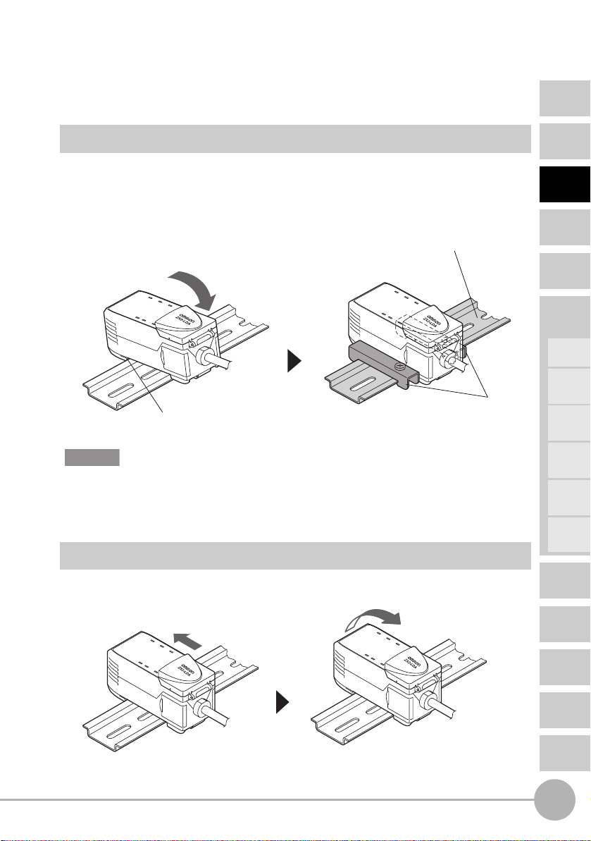
Installing the Amplifier Unit
Amplifier Units can be easily mounted to 35-mm DIN Track.
Installation Method
Hook the connector end of the Sensor Head on the DIN Track, and press in at the bottom
until the Amplifier Unit locks into place. If necessary, fix it in place by the End Plate.
DIN Track (Option)
PFP-100N (shallow type/1 m)
PFP-50N (shallow type/0.5 m)
PFP-100N2 (shallow type/1 m)
End Plate (Option)
Hook on the connector end
Important
Hook the connector end of the Sensor Head on the DIN Track first. The mounting strength may
decrease if the output cable end is hooked on the DIN Track first.
PFP-M
CONTENTS
INTRODUCTION
PREPARATION
FOR
MEASUREMENT
FLOW OF
OPERATION
BASIC
SETUP
MAIN
APPLICATIONS
& SETTING
METHODS
Height
Steps
and
Warpage
Double
Sheet
Detection
Thickness
Positioning
Removal Method
Push the Amplifier Unit and pull out from the connector end of the Sensor Head.
ZX2 User’s Manual
Installation
Eccentricity
and Surface
Deflection
DETAILED
SETTINGS
TROUBLESHOOTING
SPECIFICATIONS
INDEX
SETTING
TRANSITION
CHARTS
25

CONTENTS
INTRODUCTION
PREPARATION
FOR
MEASUREMENT
FLOW OF
OPERATION
BASIC
SETUP
MAIN
APPLICATIONS
& SETTING
METHODS
Height
Steps
and
Warpage
Double
Sheet
Detection
Thickness
Connecting Calculating Units
Use a Calculating Unit to connect Amplifier Units when performing calculations between
Amplifier Units and to prevent mutual interference between Sensor Heads.
The number of Amplifier Units that can be connected differs depending on the functions to
be used.
Function Number of Connectable Amplifier Units See:
Calculation Up to two units (Up to five units can be connected.
However, calculations are done between pairs of two.)
For (A-B) calculations
A: CH2 or later
B: CH1
CH2
(CH2-CH1)
CH3
(CH3-CH1)
CH4
(CH4-CH1)
CH5
(CH5-CH1)
Mutual interference
Up to five units Page 88
prevention
For details on the connection method, see the next page.
CH1
(A-B)
calculation:
Page 47
Thickness
calculation:
Page 57
Positioning
Eccentricity
and Surface
Deflection
DETAILED
SETTINGS
TROUBLESHOOTING
SPECIFICATIONS
INDEX
SETTING
TRANSITION
CHARTS
26
Installation
ZX2 User’s Manual
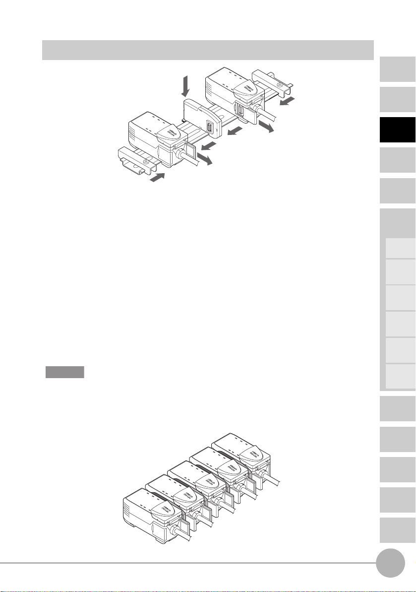
Connection Method
2
5
4
1
3
1
5
1 Open the connector cover on the Amplifier Unit.
Open the connector cover by lifting and sliding it.
2 Mount the Calculating Unit to the DIN Track.
3 Slide and connect the Calculating Unit to the Amplifier Unit connector.
4 Slide and connect the second Amplifier Unit to the Calculating Unit
connector.
5 Fix in place with the End Plate (sold separately: PFP-M).
CONTENTS
INTRODUCTION
PREPARATION
FOR
MEASUREMENT
FLOW OF
OPERATION
BASIC
SETUP
MAIN
APPLICATIONS
& SETTING
METHODS
Height
Steps
and
Warpage
Double
Sheet
Detection
Thickness
Positioning
Important
• To disconnect Amplifier Units and Calculating Units, perform the above operations in reverse
order.
• The following diagram shows the channel numbers when multiple Amplifier Units are
connected.
CH1
CH2
CH3
CH4
CH5
ZX2 User’s Manual
Installation
Eccentricity
and Surface
Deflection
DETAILED
SETTINGS
TROUBLESHOOTING
SPECIFICATIONS
INDEX
SETTING
TRANSITION
CHARTS
27
CONTENTS
INTRODUCTION
PREPARATION
FOR
MEASUREMENT
FLOW OF
OPERATION
BASIC
SETUP
MAIN
APPLICATIONS
& SETTING
METHODS
Height
Steps
and
Warpage
Double
Sheet
Detection
Thickness
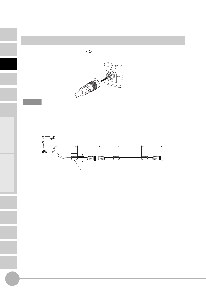
Connecting the Sensor Head to the Amplifier Unit
Installation Method
Align the position of the connector mark with the S mark on the Amplifier Unit, and
insert the connector until it is locked in place.
Important
• Extending the Sensor Head cable
An optional extension cable (ZX2-XCR) must be used.
Only one extension cable can be used.
Be sure to attach the two supplied ferrite cores within 100 mm of each end of the extension
cable.
Within 100 mm Within 100 mm Within 100 mm
30
16.5 dia.
Positioning
Eccentricity
and Surface
Deflection
DETAILED
SETTINGS
TROUBLESHOOTING
SPECIFICATIONS
INDEX
SETTING
TRANSITION
CHARTS
28
Installation
Made by TDK Corporation ZCAT1730-0730A
ZX2 User’s Manual

Removal Method
CONTENTS
To disconnect the Sensor Head, hold the Sensor Head's connector ring and the Amplifier
Unit connector, and then pull them straight out.
Connector Ring
Important
• Do not touch the terminals inside the connector.
• Prevent the connector from being subjected to static electricity.
• When the Sensor Head is replaced with a different type, set all the setting data inside the
Amplifier Unit again since it will be cleared.
(default values: → See page 123.)
INTRODUCTION
PREPARATION
FOR
MEASUREMENT
FLOW OF
OPERATION
BASIC
SETUP
MAIN
APPLICATIONS
& SETTING
METHODS
Height
Steps
and
Warpage
Double
Sheet
Detection
Thickness
Positioning
Eccentricity
and Surface
Deflection
ZX2 User’s Manual
Installation
DETAILED
SETTINGS
TROUBLESHOOTING
SPECIFICATIONS
INDEX
SETTING
TRANSITION
CHARTS
29
Wiring Diagram
CONTENTS
INTRODUCTION
PREPARATION
FOR
MEASUREMENT
FLOW OF
OPERATION
BASIC
SETUP
MAIN
APPLICATIONS
& SETTING
METHODS
Height
Steps
and
Warpage
Double
Sheet
Detection
Thickness
Positioning
Eccentricity
and Surface
Deflection
DETAILED
SETTINGS
TROUBLESHOOTING
SPECIFICATIONS
INDEX
SETTING
TRANSITION
CHARTS
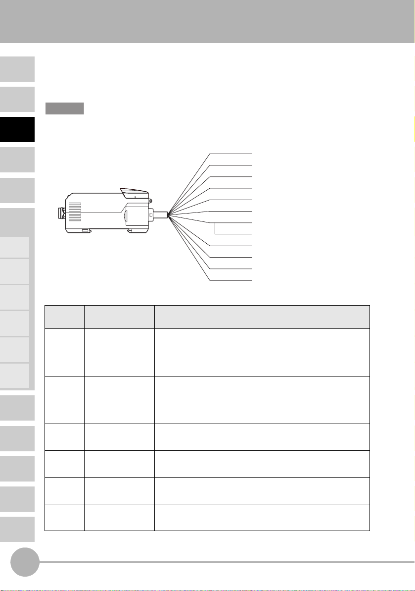
Wiring Input/Output Cables
The input/output cable has the following wires.
Important
Wire the cable correctly. Incorrect wiring may damage the Smart Sensor.
(For details on the cable’s conductor cross-section and insulation resistance, see page 136.)
Brown
White
Green
Yellow
Black
Shield
Orange
Purple
Cable
Name Function
color
Brown Power supply Connects the 10 to 30 VDC (including (p-p) 10% ripple)
power supply. When using an Amplifier Unit with a PNP
output, the power supply terminal is also the common I/O
terminal for all I/O except for the analog output.
Blue GND (0 V) The GND terminal is the 0 V power supply terminal. When
using an Amplifier Unit with an NPN output, the power
supply terminal is also the common I/O terminal for all I/O
except for the analog output.
White HIGH judgement
output
Green PASS judgment
output
Gray LOW judgment
output
The HIGH judgement output outputs judgement results
(HIGH).
The PASS judgement output outputs judgement results
(PASS).
The LOW judgement output outputs judgement results
(LOW).
Yellow Error output This is output when the system detects an error.
(For details on error messages, see page 130.)
Power supply
Blue
GND
HIGH judgement output
PASS judgement output
Gray
LOW judgement output
Error output
Analog output
Analog GND
Pink
LD-OFF input
Zero reset input
Timing input/BANK input 0
Red
Reset input/BANK input 1
30
Wiring Diagram
ZX2 User’s Manual
 Loading...