

Omron ZX2, ZX2-LD50, ZX2-LD100, ZX2-LD100L, ZX2-LD50L Short Manual
Short Manual
ZX2 Short Manual.doc Page 1 of 12
(
)
g
1 Safety precautions and correct use
Please refer to the full ZX2 user manual for the detailed explanations of the safety
precautions and the correct use.
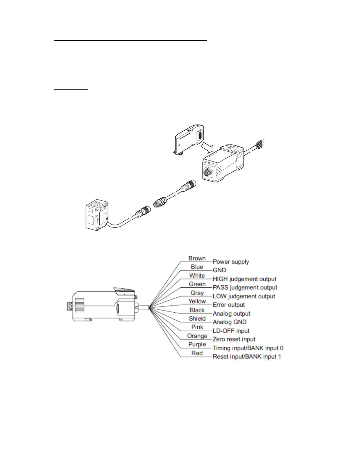
2 Wiring
Calculation unit (required
for systems with 2 or more
amplifiers)
Amplifier
Sensor head
Extension cable
(optional, max. 1
piece)
10V - 30 VDC
The HIGH judgement output is switched on if the measurement value is bigger
than the HIGH Threshold value.
The LOW judgement output is switched on if the meansurement value is
smaller than the LOW Threshold value.
The PASS judgement output is switched on if the measurement value is
between the the Low and Hi
ZX2 Short Manual.doc Page 2 of 12
h Threshold values.
)
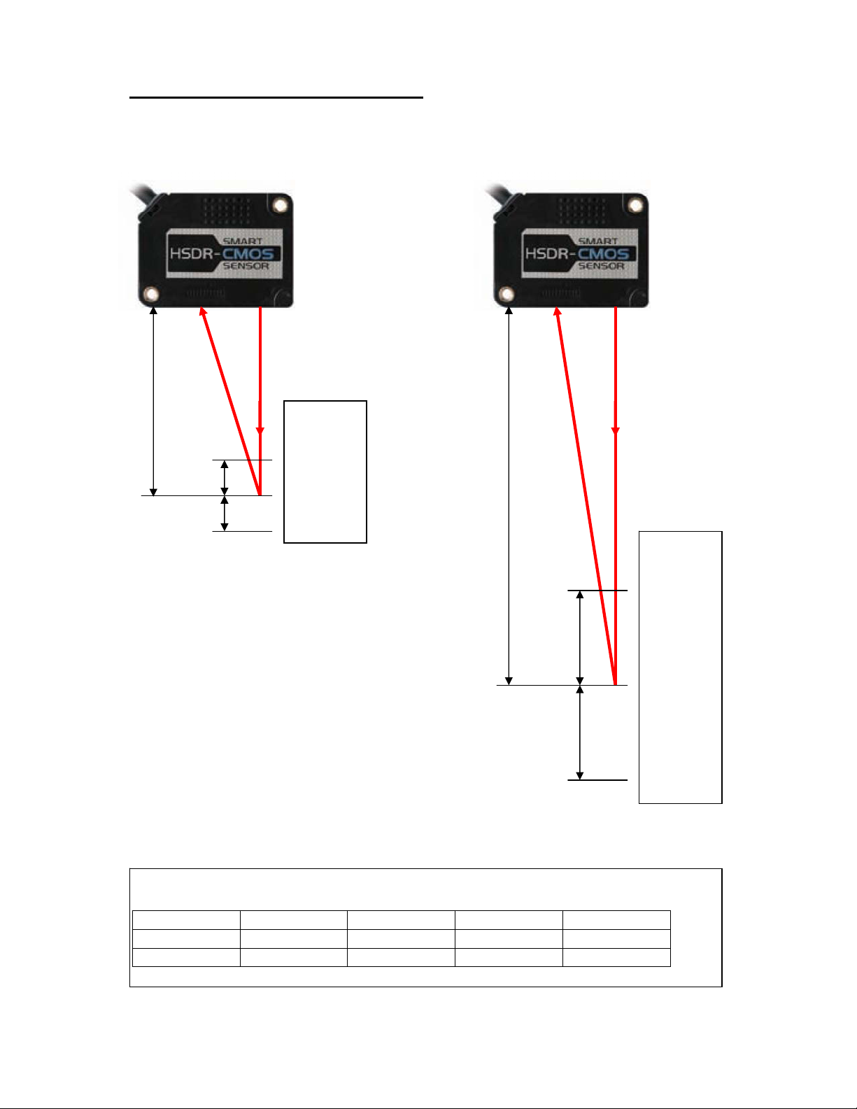
3 Default Measurement range
ZX2-LD50(L) ZX2-LD100(L
50mm
10mm
10mm
Display:
-10.000
0.000
+10.000
100mm
35mm
35mm
Display:
-35.000
0.000
+35.000
The analog output line can be set to following default ranges (see p.11 and p.12
for additional settings):
ZX2-LD50 ZX2-LD100 -5…5V 1V…5V 4mA…20mA
-10 -35 -5V +1V 4mA
+10 +35 +5V +5V 20mA
ZX2 Short Manual.doc Page 3 of 12
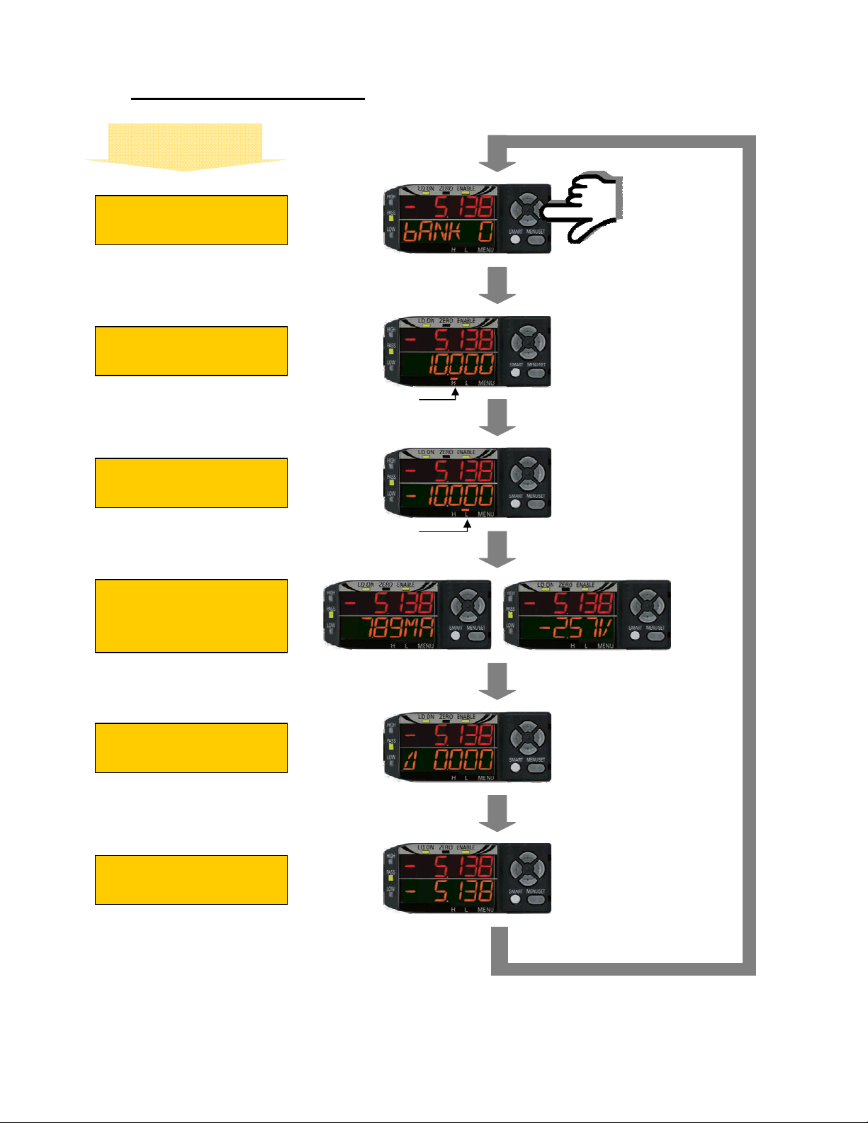
4 Display in RUN mode
Orange subdisplay
Displays the selected
bank
Displays the High
Threshold
Displays the L ow
Threshold
Displays either the
current or voltage at the
analog output
Displays the current
resolution
Displays the current
measurement value
Press right or
left button
H
L
ZX2 Short Manual.doc Page 4 of 12
 Loading...