

Omron ZX1-LD Instruction Sheet
-1-
-2-
©
OMRON Corporation 2011 All Rights Reserved.
● Meanings of Signal Words
● Alert Statements
Laser Displacement Sensor CMOS Type
Smart Sensor
ZX1-LD□□
PRECAUTIONS ON SAFETY
SAFETY PRECAUTIONS FOR USING LASER EQUIPMENT
PRECAUTIONS FOR CORRECT USE
Checking the Package Content
Do not expose your eyes to the laser radiation either directly
(i.e., after reflection from a mirror or shiny surface). Loss of
sight may possibly occur in case of the exposure to laser
high power density.
Do not disassemble the product. Doing so may cause the
laser beam to leak, resulting in the danger of visual
impairment.
Indicates a potentially hazardous situation which, if
not avoided, will result in minor or moderate injury,
or may result in serious injury or death. Additionally
there may be significant property damage.
INSTRUCTION SHEET
■ Power Supply and Wiring
• Do not impose voltage exceeding the rated voltage: 10 to 30 VDC, including 10% ripple (p-p).
• When supplying power to the Sensor, make sure that the polarity of the power is correct, and do
not connect to an AC power supply.
• Do not short-circuit the load for the open collector output. Short-circuiting the load may cause
re or damage on the Sensor.
• Connect the load correctly. Short-circuiting the load may cause re or damage on the Sensor.
• Keep the load within the rated range. Overloading may result in re or damage on the Sensor.
• Wire the product cable separately from high-voltage or power lines. Placing them in the same
wiring or the same duct may cause induction, resulting in the product malfunction or damage.
• Always turn off the power of the Sensor before connecting or disconnecting the cable or
connector.
• Do not use the Sensor for the safety circuits in nuclear power or life-critical applications.
• Implement safety measures e.g. fail-safe circuits.
■ Installation
• Make sure that all installation screws must be tighten securely.
Tightening torque: M3, 0.5N·m (ZX1-LD50□□/ZX1-LD100□□)
M4, 1.2N·m (ZX1-LD300□□/ZX1-LD600□□)
■ Others
• Do not attempt to disassemble, deform by pressure, incinerate, repair, or modify this product.
• When disposing of the product, treat as industrial waste.
• If you notice an abnormal condition such as a strange odor, extreme heating of the unit, or
smoke, immediately stop using the product, turn off the power, and consult your dealer.
The ZX1-LD uses a laser as the light source. Lasers are classied based on EN standard (EN 60825-1)
■ Installation Location
Do not install the product in locations subjected to the following conditions:
• Surrounding air temperature outside the rating
• Rapid temperature uctuations (causing condensation)
• Relative humidity outside the range of 35 to 85%
• Presence of corrosive or ammable gases
• Presence of dust, salt, or iron particles
• Direct vibration or shock
• Reection of intense light (such as other laser beams, electric arc-welding machines, or
ultra-violet light)
• Direct sunlight or near heaters
• Water, oil, or chemical fumes or spray, or mist atmospheres
• Strong magnetic or electric eld
• In the water, rain, or outdoors
■ Power Supply and Wiring
• Do not supply the power to the Sensor before checking the I/O wiring.
• Ground the FG terminal when using a commercially-available switching regulator.
• If the power supply line is subject to surges, connect a surge absorber that meets the conditions
of the operating environment.
• Do not turn ON the power after wiring before making sure that the power supply is connected
correctly; there are no faulty connections, e.g. load short-circuits; the load current is correct.
Incorrect wiring may result in failure.
• Use a ZX0-XC□R Extension Cable (sold separately) to extend the Sensor’s cable. Use only one
cable. Do not extend the cable for the Sensor to a length exceeding 20 m.
• The display and indicators turn ON after approx. 2.5 seconds after the power is turned ON.
■ Warming Up
• After turning ON the power, allow the Sensor to warm up for approx. 30 minutes prior to use.
The circuitry is not stable immediately after turning the power ON, and the values gradually
change until the Sensor is completely warmed up. When using LD-OFF input for a long period
of time, perform warmng up for more than 30 minutes after cancelling LD-OFF.
■ Maintenance and Inspection
• Always turn OFF the power of the Sensor before connecting or disconnecting the cable or for
making adjustment.
• Do not use thinner, alcohol, benzene, acetone, or kerosene to clean the Sensor.
• If considerable foreign matter or dust collects on the glass surface of the front of Sensor, use a
blower brush (for camera lenses) to blow off the foreign matter. Avoid blowing it off with your
breath. For a small amount of foreign matter or dust, gently wipe with a soft cloth. Do not wipe
hard. The damaged glass surface may result in detection errors.
■ Sensing Object
The product cannot accurately measure the following types of objects: Transparent objects,
objects with an extremely low reective sensor ratio, objects smaller than the spot diameter,
objects with a large curvature, excessively inclined objects, etc.
WARNING
● Explanation of Signs
● Laser beam
Indicates caution on potential laser beam hazard.
● Do not disassemble
Indicates prohibition when there is a risk of minor injury from
electrical shock or other source if the product is disassembled.
WARNING
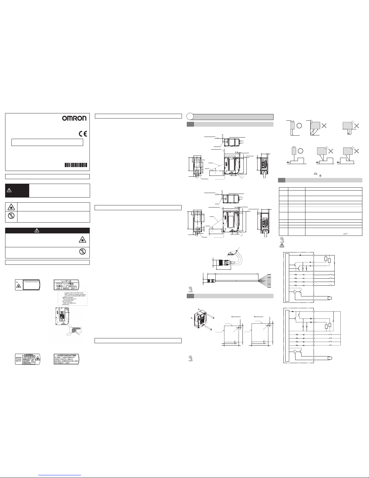
■ I/O Circuit Diagram <NPN Output Type>
■ I/O Circuit Diagram <PNP Output Type>
<ConnectorJointModel>
Installation
1
Dimensions
1-1
Wiring
1-3
The table below shows individual external I/O wires and their roles.
The individual wire colors and roles are the same between pre-wired and
connector joint models.
Wire the Sensor correctly. Unused wires must be insulated. Incorrect wiring may
result in damage to the Sensor.
Role
Brown
Wire color
Name
Connect to 10 to 30 VDC (including 10% ripple (p-p)). Used as the
common I/Os terminal for all I/O except monitor output for a PNP output type.
0-V power supply terminal. Used as the common I/Os terminal
for all I/O except monitor output for an NPN output type.
Blue
GND
Outputs the CH1 judgment result.
White
OUT1 Judgment output
Outputs the CH2 judgment result.
Green
OUT2 Judgment output
TUNE1 input
TUNE2 input
Outputs the current value according to the measurement result.
(4 to 20 mA)
Black
Analog output
0-V ground line for monitor output.
Connect this line separately from the blue (0 V) GND.
[Important] Be sure to connect to blue (0 V).
Shield
Analog GND
Inputs tuning to CH1.
Inputs tuning to CH2.
Pink
Zero reset input
Used to execute or cancel zero reset.
Purple
Red
LD-OFF input
Power supply
Orange
(Unit:mm)
■ZX1-LD300□/ZX1-LD600□
■ZX1-LD50□/ZX1-LD100□
10.2
A*
L*
50.1
1.9
66
57
15.5
4.5
45.6
55.8
13.6
27.2
10.7
227
10.1
17
13.6
A*
L*
10.2
47
52.5
3.246.1
11.7
2
35.3
Reference surface
2-3.2 dia.
(Mounting hole)
Receiver
axis
Emitter
axis
10.5
Emitter axis
42.3
10.5
24.1
14.23
16.77
10.1
15.1
* ZX1-LD50□: L=50, A=21°
ZX1-LD100□: L=100, A=11.5°
* ZX1-LD300: L=300, A=6.6°
ZX1-LD600: L=600, A=3.4°
Emitter center
Reference surface
• Sensor: 1
• Instruction sheet (this sheet): 1 each (Japanese and English)
• FDA Certification label : 1
• Laser Warning Label : 1 each (Japanese and English)
(The explanatory labels are attached to ZX1-LD□□L instead of the warning explanation labels.)
Reference surface
Emitter
axis
Reference surface
2-4.5 dia.
(Mounting hole)
Reference surface
Emitter center
Receiver
axis
Emitter
axis
Thank you for selecting an OMRON product. This sheet primarily
describes precautions required in installing and operating the product.
• A specialist who has the knowledge of electricity must treat the product.
• Please read this manual carefully, and use it correctly after thoroughly
understanding the product.
• Please keep this manual properly for future reference whenever
it is necessary.
■ Labeling on Laser Use
The ZX1-LD has the following WARNING label or explanatory label on the side of the sensors.
Emitter center position mark
Emitter center
position mark
Emitter center position mark
Emitter center
position mark
Vinyl insulated round-shaped robot cable
Dia 6.5 9-wire (cross section of conductor:
0.125 mm
2
/insulator diameter: 0.7 mm)
Standard length: 2 m
Root section bending disabled length: 0 mm
Minimum bending radius: 39 mm
Vinyl insulated round-shaped robot cable
Dia 6.5 9-wire (cross section of conductor:
0.125 mm
2
/insulator diameter: 0.7 mm)
Standard length: 2 m
Root section bending disabled length: 0 mm
Minimum bending radius: 39 mm
Reference surface
10 to 30 VDC
Shield: Analog GND
Black: Analog output
300 Ω max.
Current output
4 to 20 mA
Red: LD-OFF input
Purple: Zero reset input
Pink: TUNE2 input
Orange: TUNE1 input
Blue: GND (0 V)
Green: OUT2
judgment output
White: OUT1
judgment output
Brown: 10 to 30 VDC
Load
Load
Internal circuit
Load
Shield: Analog GND
Black: Analog output
Red: LD-OFF input
Purple: Zero reset input
Pink: TUNE2
Orange: TUNE1
Blue: GND (0 V)
Brown: 10 to 30 VDC
Load
Internal circuit
Load
Load
10 to
30 VDC
Current output
4 to 20 mA
300 Ω max.
Green: OUT2
judgment output
White: OUT1
judgment output
PRECAUTIONS FOR SAFE USE
37.8
18.7 2.5
2.4
50.3
21.3 3
3
<ExtensionCable>
ZX1-LD300□6/ZX1-LD600□6
■ ZX1-LD50□6/ZX1-LD100□6
15 dia.
37.3 L*
Ø15.5
39.8
* The length of L is as follows:
ZX0-XC10R: 10 m, ZX0-XC20R: 20 m
The extension cable is the robot cable, the same as the cable of the Sensor Unit.
Vinyl insulated round-shaped robot cable
Dia 6.5 9-wire (cross section of conductor:
0.125 mm
2
/insulator diameter: 0.7 mm)
Standard length: 0.5 m
Sensor root section bending disabled length: 0 mm
Connector section bending disabled length: 40 mm
Minimum bending radius: 39 mm
To mount ZX1-LD50 and ZX1-LD100□, use M3 screws (tightening torque: 0.5 N·m) and
ZX1-LD300□ and ZX1-LD600, M4 screws (tightening torque: 1.2 N·m).
Mounting Sensor
1-2
Do not touch the sensor emitter and receiver sections. Correct detection may
not be possible if fingerprints are attached to these areas. If fingers have
inadvertently touched the areas, wipe the areas using a soft, clean cloth.
ZX1-LD300□
ZX1-LD600□
ZX1-LD50□
ZX1-LD100□
2-M3
P=0.5
3.2±0.1
49.3±0.1
23.6±0.1
35.3±0.1
4.5±0.1
2-M4
P=0.7
61.5±0.1
30.1±0.1
45.6±0.1
Reference
surface
Mounting hole dimensions (Unit: mm)
Emitter/Receiver direction
Reference
surface
Reference
surface
Reference
surface
<Detection Near the Wall Surface>
<Detection of Workpiece with Level Difference>
<Cavity Detection>
Stable detection is possible
regardless of level difference.
Level difference may cause
an abnormal detection value.
The Sensor is less
inuenced by ambient
lighting.
The Sensor is easily inuenced by
ambient lighting, which may cause
detection value variations. *
Detection is not possible if
the emitter or receiver section
is blocked.
■ Caution on Mounting Direction
* Before performing tuning, apply mat paint on the wall surface or turn ON the background suppression
function to avoid laser light reection.
Refer to " 5. Background suppression function,
Detailed Settings"
The following precautions must be observed, since they are essential to ensure safety in operation.
■ Installation Environment
•Do not use the Sensor in locations subject to explosive or ammable gases.
• To ensure safety in operation and maintenance, do not install the Sensor near high-voltage
equipment or power devices.
ON: Laser turns OFF (radiation stop). In this state, analog output, digital
display, judgment output and judgment output display are output based on
keep function settings. The digital display shows [ ].
Using in a country other than U.S.
・For countries other than Japan and U.S., warning labels
or explanatory labels must be replaced by English ones
(supplied with the product). EN60825-1 is provided for
products used in Europe, and the content of this
standard differs.
・The ZX1-LD is categorized as a Class 2 or Class 1
device as stipulated in EN60825-1:2007.
When using devices in which ZX1-LD is installed
in the U.S., the devices are subjected to the U.S.
FDA (Food and Drug Administration) laser
regulations. ZX1 series is classied into Class2 or
Class 1 by the standard of IEC/EN60825-1
according to deviations of Laser Notice NO.50 of
this standard, and reported to CDRH (Center for
Devices and Radiological Health).
Accession Number
(ZX1-LD□□ : 1210041-000)
(ZX1-LD□□L : 1210041-001)
Replace the WARNING label or explanatory label with the corresponding English label and
put the FDA Certication label. (supplied with the sensor)
Please make sure that the label are afxed at the correct locations as indicated.
Laser WARNING label
FDA Certification label
* 0 1 9 9 5 6 0 - 4 D *
警告
レーザ光
ビームをのぞきこまないこと
クラス2レーザ製品
Max.1.0mW 2.5ms
半導体レーザ
660nm
JISC6802:2011
・ZX1-LD□□
LaserWarningLabel
・ZX1-LD□□L
ExplanatoryLabel
・ZX1-LD□□
LaserWarningLabel
(Class2label/Aperturelabel)
・ZX1-LD□□L
ExplanatoryLabel
・ZX1-LD□□
・ZX1-LD□□L
ExplanatoryLabel
-3-
-4-
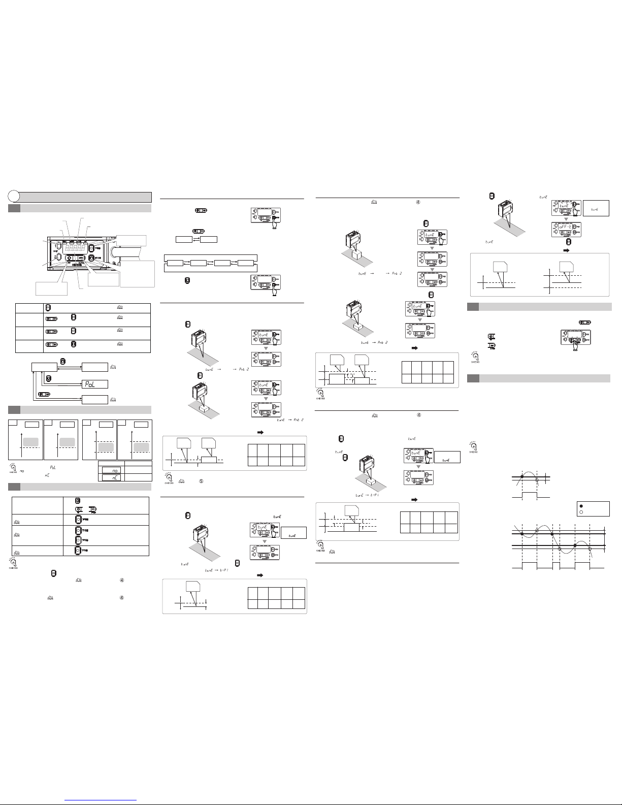
1. Hold the button (minimum 3 and less than 5 seconds) until [ ] blinks
without a workpiece.
2. When [ ] starts blinking, release the button.
The display changes [ ] [ ] and 1-point tuning is completed.
The measured value display returns.
Used to judge the presence/absence of a workpiece by referring to the pre-determined
background (reference surface).
Used to assign the upper and lower limits to one actual workpiece and judge
if the workpiece is within the range.
●
1-point Tuning
2. Hold the button (3 to less than 5 seconds) until [ ] blinks with a workpiece
to detect on the reference surface.
1. Set the AREA item in the menu to "ON" and return to the measured value display.
3. When [ ] starts blinking on the display,
release the button.
●
1-point Area Tuning
(3) Detect for Workpiece Presence/Absence
(Tuning Only Using Reference Surface)
(5) Set Plus/Minus (±) Tolerance
●
Threshold Value Setting
The OUT1 indicator keeps blinking while "Threshold 1/ Threshold 1H/ Threshold 1L"
is being changed.The OUT2 indicator keeps blinking while "Threshold 2/ Threshold
2H/ Threshold 2L" is being changed.
(2)
Detect for Workpiece Presence/Absence
1. Press the button (within 1 sec.) once without a workpiece.
3. Set the workpiece at the desired lower limit and lightly press the button.
To loosen or tighten the ON/OFF switching conditions, use the buttons for
minute adjustment of the threshold values.
The order of the workpiece does not matter.
Used to distinguish between two objects with different height from the Sensor e.g.
OK and NG, workpiece and background (reference surface) or workpieces A and B.
●
2-point Tuning
2. Lightly press the button once again with a workpiece.
The display changes [ ] [ ]
and 2-point tuning is completed.
The measured value display returns.
The order of the workpiece does not matter.
Increase threshold
Decrease threshold
Refer to " 7. Area Output, Detailed Settings"
To set plus and minus threshold values using "0" as the background, use the zero
reset function to reset the distance to "0". Then, perform 1-point area tuning.
The display changes [ ] [
t-p1
] [ ].
0.00
Hold for 3 to
less than 5 sec
until [ ] blinks.
TUNE
TUNE
TUNE
TUNE
TUNE
TUNE
TUNE
UP/DOWN
t-p1
t-p2
Setting is Completed
t-p1
Setting is Completed
t-p2
The display changes [ ] [ ] and 2-point tuning is completed.
The measured value display returns.
Setting is Completed
Hold for 3 to
less than 5 sec
until [ ] blinks.
t-p1
Setting is Completed
Refer to " Convenient Setting Features (1)"
Refer to " Error Messages" .
2. The channel display changes in the following sequence
by pressing the button.
3. Press the button to return to measurement mode.
1. Briefly press the button in Measurement
mode.
●
CH Setting Mode
(1)
Switch Channel to Set Threshold
ch-1
ch-2
ch1h
ch1l
ch2h
ch2l
<Area Output is ON>
Threshold 1 Threshold 2
Threshold 1H Threshold 1L Threshold 2H Threshold 2L
ch-1
0.00
UP/DOWN
UP/DOWN
MODE
1. Hold the button (5 sec. or longer) until [ ] blinks rapidly without a workpiece.
(6) When (2) to (5) Methods Failed
Used to judge the presence/absence of a workpiece using the pre-determined background
(reference surface) as the reference. Unlike 1-point tuning, this method focuses on the detection
of the absence of workpiece. Insufficient light level or outside-range errors caused by
complicated workpiece appearance are judged as "the presence of the workpiece".
Used to assign the upper and lower limits to the distance from the reference surface and judge
if a workpiece is within the range. Unlike 2-point tuning, this method focuses on the detection of
the absence of workpiece. Insufficient light level or outside-range errors caused by complicated
workpiece appearance are judged as "the presence of the workpiece".
2. When [ ] in the display starts blinking rapidly, release the button.
●
Tuning mode without Workpiece (Area Output is OFF)
●
Tuning mode without Workpiece (Area Output is ON)
Threshold H
Threshold
Threshold L
Reference surface
Reference surface
ON
OFF
OFF
ON
ON
<Tuning mode without Workpiece> <Area Tuning mode without Workpiece>
TUNE
TUNE
Sensor Sensor
Hold for 3 to
less than 5 sec
until [ ] blinks
rapidly.
Setting is Completed
1. Select "ON" for area output in menu setting mode to return to measurement mode.
●
2-point Area Tuning
2. Set the workpiece at the desired upper limit and lightly press the button.
(4) Set Upper Limit and Lower Limit (Using Area Output)
Refer to " 7. Area Output, Detailed Settings"
Used to judge if the workpiece is within the range by using the upper limit and
lower limit workpieces.
TUNE
t-p1
The display changes [ ] [
t-p1
] [ ].
pnt 2
Fine Adjustment of Threshold Value
2-4
③
Settings
2
Tuning
2-3
2-2
Setting and Display Overview
Output and Threshold Value
2-1
MODE
UP/DOWN
Hold for
min. 3 sec.
Less than 3 sec.
Menu Setting mode
Refer to "2-3 (1)".
CH Setting mode
Measurement mode
0.00
MODE
Less than 1 sec.
Threshold Setting mode
ch-1
No operation for min. 2 sec.
10.00
■
Switching to Individual Modes
■
Other Button Operation
Tuning
Zero reset setting
Zero reset cancel
Key lock setting/
cancel
button
button+button
simultaneouslyforlessthan3sec.
button+button
simultaneouslyformin.3sec.
button+button
simultaneouslyformin.3sec.
Refer to "2-4".
Refer to "2-3"
Refer to "③ (2)"
Refer to "③ (1)"
Refer to "③ (1)"
<Area Output is OFF> <Area Output is ON>
Measured value
CH1 CH1
OUT1 OUT2
CH2 CH2
OFF
OFF
OFF
OFF
OFF
OFF
Threshold
1
Threshold
2
Threshold
1H
Threshold
1L
Threshold
2H
Threshold
2L
Measured value
Measured value Measured value
OUT1 OUT2
MODE
UP/DOWN
UP/DOWN
UP/DOWN
TUNE
TUNE
TUNE
ON ON
ON ON
• TUNE1 input (external input terminal) can also replace the button operations
for tuning to CH1.
Tuning can be performed for TUNE2 to CH2.
•
When performing tuning, threshold values are recorded in EEPROM (non-volatile
memory) in the sensor. The writing life of EEPROM is 100,000 times. Be careful of
writing life when performing measurement-by-measurement tuning.
• The allocation of button and external input terminals can be fixed by
changing the tuning type.
Refer to " 2.Tuning Type, Detailed Settings"
Refer to "2-3 (1)", "2-3 (4)"
Refer to "2-3 (2)", "2-3 (3)"
Refer to "2-3 (5)"
1-point tuning
2-point tuning
Tuning mode without workpiece
CH setting mode
TUNE
Press button for 3 to 5 seconds.
Press button once for the 1st point.
Press button once for the 2nd point.
Press button for 5 seconds.
■
Quick Reference for Tuning Operation (Perform tuning after selecting a CH)
(Near)
(Far)
. . . .
[ZERO]Zero reset indicator (Orange)
[ST]Smart tuning indicator (Blue)
OUT2 Output indicator
Orange)
OUT1 Output indicator
(Orange)
Turns ON when tuning is performed with the background
suppression function ON.
Turns ON in MENU setting mode.
[MENU]Menu Indicator (Orange)
[LD ON]Laser ON indicator (Green)
Turns ON when zero reset is set.
Turns ON when sensor is emitting laser.
Digital display
Displays the displacement volume in
Measurement mode and setting
item/setting value in other modes.
■
Nomenclature and Function
Turns ON when the value
exceeds Threshold 1 or within
the range of 1L to 1H.
Turns ON when the value exceeds
Threshold 2 or within the range
of 2L to 2H.
[TUNE]button
Used to perform tuning.
[MODE]button
Switches between
Measurement mode and MENU
setting mode by holding it for
3 seconds or longer. Switches
to CH Setting mode when it is
pressed less than 3 seconds.
[DOWN]button
Used to change a
threshold value or select
a setting item.
[UP]button
Used to change a
threshold value or select
a setting item.
Refer to " 5. Background suppression function, Detailed Settings"
88888
The display changes [ ] [ ] and 1-point area tuning is completed.
The measured value display returns.
Sensor
Threshold
H
D
D 0.13 0.4 2 9
Threshold
L
Sensor
Lower limit
workpiece
ON
OFF
OFF
The margin (D) for the upper/lower limit of
each model is as follows (fixed value):
Model
ZX1LD50
□
ZX1LD100
□
ZX1LD300
□
ZX1LD600
□
D
Background
(Reference surface)
Upper limit
workpiece
Unit (mm)
D
D
0.13 0.4 2 9
ON
OFF
OFF
D
ZX1LD50□
ZX1LD100□
ZX1LD300□
ZX1LD600□
Sensor
Workpiece
Threshold H
Threshold L
Background
(Reference
surface)
The margin (D) for the upper/lower limit of
each model is as follows (fixed value):
Model
Unit (mm)
The above figures represent the behaviors when
the output polarity [ ] is set to normally-open
[ ] (initial value). If the polarity is set to
normally-closed [ ], the ON/OFF polarities in
the figures are reversed.
Output polarity
Output at detection
ON
OFF
Press button to enter CH setting mode, and then
press or button to select a CH.
MODE
•
When setting the background suppression function to ON and performing tuning,
the measurement value and sensitivity level can be limited according to the sensitivity.
Use it when abnormal distance is detected due to diffuse reflection caused by surrounding walls, etc.
Sensor
Threshold
Reference surface
Sensor
Workpiece
ON
OFF
Without workpiece
0.2 0.7 3 15
D
ZX1LD50□□
ZX1LD100□□
ZX1LD300□□
ZX1LD600□□
The margin (D) for the Threshold of
each model is as follows (fixed value):
Model
Unit (mm)
D
Threshold
Reference surface
Without workpiece
Sensor
ON
OFF
0.2 0.7 3 15
D
ZX1LD50□□
ZX1LD100□□
ZX1LD300□□
ZX1LD600□□
The margin (D) for the Threshold of
each model is as follows (fixed value):
Model
Unit (mm)
D
Fine Adjustment of Hysteresis Width
2-5
●
Hysteresis Width Setting
A minute step can be judged by adjusting the hysteresis width according to the
workpiece. However, note that the judgment output varies if lowering the hysteresis
width while the displacement value is varying due to moving workpiece or low
reection light intensity.
●
What is Hysteresis Width?
A point in which a judgment output turns from OFF to ON is called an operating
point, and a point in which a judgment output turns from ON to OFF is called a return
point. On this sensor, threshold means operating point, and a distance to the return
point can be set based on the hysteresis width.
Note that the direction where the hysteresis width is set for the threshold differs
depending on ON/OFF of the area output.
Threshold
HysteresisWidth
HysteresisWidth
Judgmentoutput
Judgmentoutput
AreaoutputisOFF
Measuredvalue
Measuredvalue
AreaoutputisON
Operatingpoint
Returnpoint
ON
OFF
ThresholdL
ON
OFF
ThresholdH
 Loading...