

Page 1
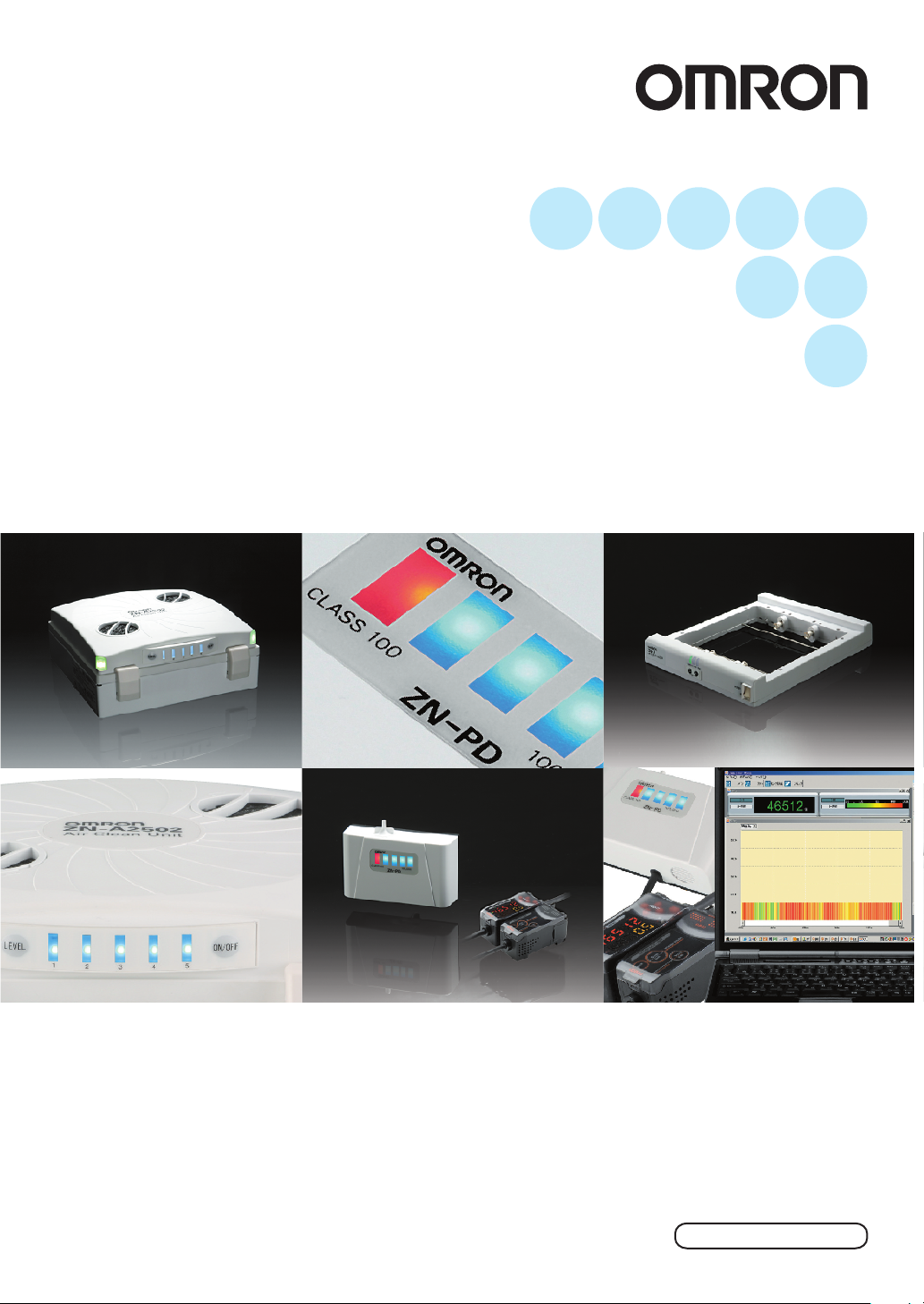
Clean Sensing System
ZN Series
System Manual
Cat. No. Z267-E1-01
Page 2

Introduction
Thank you for purchasing the ZN.
This manual provides only information, such as system components and setup procedures, that
is required when using the ZN Series in a system.
For details on product functions, performance and handling methods of individual products, refer
to the Instruction Sheet packaged with the respective product.
When using the ZN, be sure to observe the following:
• The ZN must be operated by personnel knowledgeable in electrical engineering.
• To ensure safe use of the product, please read the Instruction Sheet packaged with each
product and this manual to deepen your understanding of the product.
• Please keep this manual and the Instruction Sheet packaged with each product in a safe place
so that they can be referred to whenever necessary.
Page 3
Introduction
Section 1
Section 2
Section 3
Section 4
APPLICATION CONSIDERATIONS (Please Read)
FEATURES
UPGRADING THE SYSTEM
BASIC KNOWLEDGE OF CLEAN SENSING SYSTEMS
APPENDICES
Introduction
‚Í‚¶‚ß‚É ‘æ 1 Í‘æ 2 Í‘æ 3 Í‘æ 4 Í
Section 1 Section 2 Section 3 Section 4
System Manual
Clean Sensing System
ZN Series
Page 4

Introduction
Introduction
READ AND UNDERSTAND THIS DOCUMENT
Please read and understand this document before using the products. Please consult your OMRON
representative if you have any questions or comments.
WARRANTY
OMRON’s exclusive w arranty is that the products are f ree from defects in materials a nd workmanship for a
period of one year (or othe r pe ri od if specified) from date of sale by OMRO N .
OMRON MAKES NO WARRANTY OR REPRESENTATION, EXPRESS OR IMPLIED, REGA RDING NONINFRINGEMENT, MERCHANTABILITY, OR FITNESS FOR PARTICULAR PURPOSE OF THE PRODUCTS.
ANY BUYER OR USER ACKNOWLEDGES THAT THE BUYER OR USER ALONE HAS DETERMINED THAT
THE PRODUCTS WILL SUITABLY MEET THE REQUIREMENTS OF THEIR INTENDED USE. OMRON
DISCLAIMS ALL OTHER WARRANTIES, EXPRESS OR IMPLIED.
LIMITATIONS OF LIABILITY
OMRON SHALL NOT BE RESPONSIBLE FOR SPECIAL, INDIRECT, OR CONSEQUENTIAL DAMAGES,
LOSS OF PROFITS OR COMMERCIAL LOSS IN ANY WAY CONNECTED WITH THE PRODUCTS,
WHETHER SUCH CLAIM IS BASED ON CONTRACT, WARRANTY, NEGLIGENCE, OR STRICT LIABILITY.
In no event shall responsi bility of OMRON for any act exceed the individual price of the product on which
liability is asserted.
IN NO EVENT SHALL OMRON BE RESPONSIBLE FOR WARRANTY, REPAIR, OR OTHER CLAIMS
REGARDING THE PRODUCTS UNLESS OMRON’S ANALYSIS CONFIRMS THAT THE PRODUCTS WERE
PROPERLY HANDLED, STORED, INSTALLED, AND MAINTAINED AND NOT SUBJECT TO
CONTAMINATION, ABUSE, MISUSE, OR INAPPROPRIATE MODIFICATION OR REPAIR.
SUITABILITY FOR USE
THE PRODUCTS CONTAINED IN THIS DOCUMENT ARE NOT SAFETY RATED. THEY ARE NOT DESIGNED OR
RATED FOR ENSURING SAFETY OF PERSONS, AND SHOULD NOT BE RELIED UPON AS A SAFETY COMPONENT OR PROTECTIVE DEVICE FOR SUCH PURPOSES.
Please refer to separate catalogs for OMRON’s safety rated products.
OMRON shall not be responsible for conform ity with any standards, codes, or regulations that apply to th e
combination of produc ts in the customer’s application or us e of th e pr oduct.
At the customer’s request, OMRON will provide applicable third party certification documents identifying ratings
and limitations of use that apply to the products. This information by itself is not sufficient for a complete
determination of the suitability of the produ cts in comb ination w ith the en d produc t, machi ne, syste m, or other
application or use.
The following are some examples of applications for which particular attention must be given. This is not
intended to be an exhaustive list of all possible uses of the products, nor is it intended to imply that the uses
listed may be suitable for the p ro ducts:
• Outdoor use, uses inv olving potential chemical contamination or electrical interference, or conditions or
uses not described in this document.
ZN
System Manu al
ii
Page 5

Introduction
• Nuclear energy control systems, combustion systems, railroad systems, aviation systems, medical
equipment, amu sem ent ma chi ne s, v eh ic le s, saf et y eq ui pme nt , an d ins t al la t io ns su bj ec t t o separate industry
or government regulations.
• Systems, machin es, and equipment that could present a ris k to lif e or pro per t y.
Please know and obse rv e all p ro hi bi tio ns of use applicable to the products.
NEVER USE THE PRODUCTS FOR AN APPLICATION INVOLVING SERIOUS RISK TO LIFE OR
PROPERTY WITHOUT ENSURING THAT THE SYSTEM AS A WHOLE HAS BEEN DESIGNED TO
ADDRESS THE RISKS, AND THAT THE OMRON PRODUCT IS PROPERLY RATED AND INSTALLED FOR
THE INTENDED USE WITHIN THE OVERALL EQUIPMENT OR SYSTEM.
PERFORMANCE DATA
Performance data given in this document is provided as a guide for the user in determining suitability and does
not constitute a warranty. It may represent the result of OMRON’s test conditions, and the users must correlate
it to actual application requirements. Actual performance i s su bj ect t o th e O M RO N Warranty and Limitations of
Liability.
CHANGE IN SPECIFICATIONS
Product specifications and accessories may be changed at any time based on improvements and other
reasons.
Introduction
It is our practice to change model numbers when published ratings or features are changed, or when significant
construction chang es are made. However, some specifications o f the product may be changed without any
notice. When in do ubt, special m odel numbe rs may be a ssigned to fix or establish key s pecificat ions for your
application on your request. Please consu lt with your OMRON repres entative at any time to conf irm actual
specifications of purchased products.
DIMENSIONS AND WEIGHTS
Dimensions and weights are nominal and are not to be used for manufacturing purposes, even when
tolerances are shown.
ERRORS AND OMISSIONS
The information in this do cument has been carefully checked and i s believed to be accurate; however, no
responsibility is assum ed for clerical, typographical, or proofreading errors, or omissions.
PROGRAMMABLE PRODUCTS
OMRON shall not be responsible for the user’s prog ra m m in g of a pro gr ammable product, or any conse quence
thereof.
COPYRIGHT AND COPY PERMISSION
This document shall not be copied for sales or promotions w ithout permission.
This document is protected by copyri ght and is inten ded solely for use in conjunc tion with the pr oduct. P lease
notify us before cop ying or reproducing this docum ent in any manner, for any other purpose. I f copying or
transmitting this document to another, please copy or transmit it in its entirety.
ZN
System Manu al
iii
Page 6

Introduction
Precautions for Safe Use
Introduction
Precautions for Safe Use
The following points are important to ensure safety, so make sure that they are strictly observed.
■ Power Supply and Wiring
• When connecting multiple Air Clean Units to build a system, use a commercially
available LAN cable (straight type: Category 5E or higher).
• On models that can be connecte d t o A ir Clea n Units, such as the Air P artic le S ens or
(ZN-PDA12) and Interfac e Unit (ZN-SF12), use the cable from the body to directly
connect to the unit.
• To extend the cable mentioned above, a commercially available LAN connector
female to female, straight type) and a LAN cable (straight type: Category 5E or
higher) must be used.
• The cables must be 100 m or shorter in total length.
For details on other precautions for safe use and precautions for correct use,
refer to the Instruction Sheet for the respective device, and make sure that they
are strictly observed.
iv
ZN
System Manu al
Page 7
Editor's Note
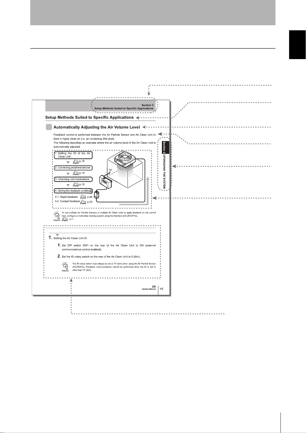
● Title of each section
● Header
● Cross-header
● Index label
● Overview and points of the
function described
● Operation procedure and supplementary explanat ion
Indicates the contents of the page.
Shows the chapter number and contents.
Shows the operation flow and setup
method.
Explains the operation procedure and the display status
resulting from execution of the operation.
Helpful information regarding operation and reference
pages is introduced here using symbols.
* This page does not exist.
● Overview of the section
Page Format
Introduction
Editor's Note
Introduction
System Manu al
ZN
v
Page 8
Introduction
Editor's Note
Introduction
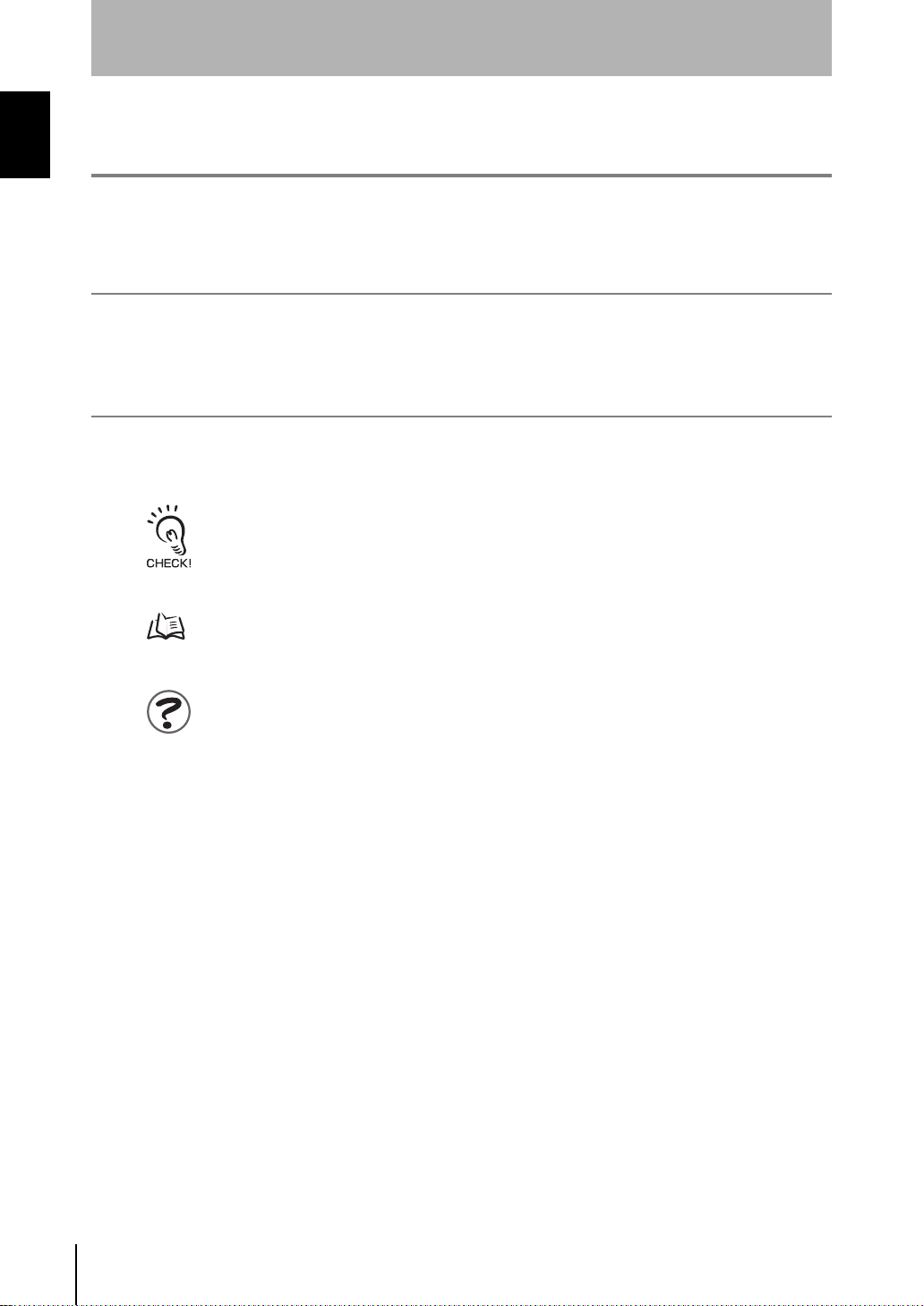
Notational Conventions
■ Menu
In this manual, menu items displayed on the screen are enclosed with [ ].
■ Operation procedure
Operation steps are numbered to indicate their order .
■ Visual Aids
Indicates points that are important to achieve the full product performance, such as operational
precautions and application procedures.
Indicates pages where related information can be found.
Indicates information helpful in operation.
vi
ZN
System Manu al
Page 9
CONTENTS
Introduction
CONTENTS
Introduction
Precautions for Safe Use iv
Editor's Note v
Page Format v
Notational Conventions vi
CONTENTS vii
Section 1 FEATURES 1
What is the "Clean Sensing System?" 2
System Features 2
Features of the Clean Sensing System 4
System Configuration Examples 7
Direct Clean Sensing System 7
Multi-Clean Sensing System 11
CONTENTS
Section 2 UPGRADING THE SYSTEM 13
Before Upgrading the System 14
Flow of Operations for Upgrading the System 14
Installing the Exclusive Monitoring Software 15
Setup Methods Suited to Specific Applications 18
Automatically Adjusting the Air Volume Level 18
Monitoring/Logging the Amount of Particles 25
Detecting the Cleanliness of Multiple Processes 31
ZN
System Manu al
vii
Page 10

Introduction
CONTENTS
Introduction
Section 3 BASIC KNOWLEDGE OF CLEAN SENSING SYSTEMS 35
Feedback Control 36
CONTENTS
What is "Feedback?" 36
How Feedback Control Works 40
Clean Sensing 44
Principle of "Particle Count" 44
What is "Cleanliness?" 45
Section 4 APPENDICES 47
Maintenance 48
Troubleshooting 50
Troubleshooting 50
Error Messages and Countermeasures 51
Specifications and Dimensions 53
List of Products 66
INDEX 69
Revision History 72
viii
ZN
System Manu al
Page 11
Section 1
FEATURES
What is the "Clean Sensing System?" 2
System Features 2
Features of the Clean Sensing System 4
System Configuration Examples 7
Direct Clean Sensing System 7
Multi-Clean Sensi ng Sy st em 11
Section 1 FEATURES
System Manu al
ZN
1
Page 12
Section 1
OPE1
OPE2
OPE3
■ Clean Monitoring System (ZN-SFW Series)
Monitoring the amount of particles at multiple points in
manufacturing processes is important in improving
product quality. By connecting Interface Units, you can
log the measured data of Air Particle Sensors at up to ten
locations at once on a personal computer.
The Electrostatic Sensor (ZJ-SD) also can be connected,
which means that you can al so asce rtain the re latio nship
between the amount of s tatic electricity and the amount
of particles.
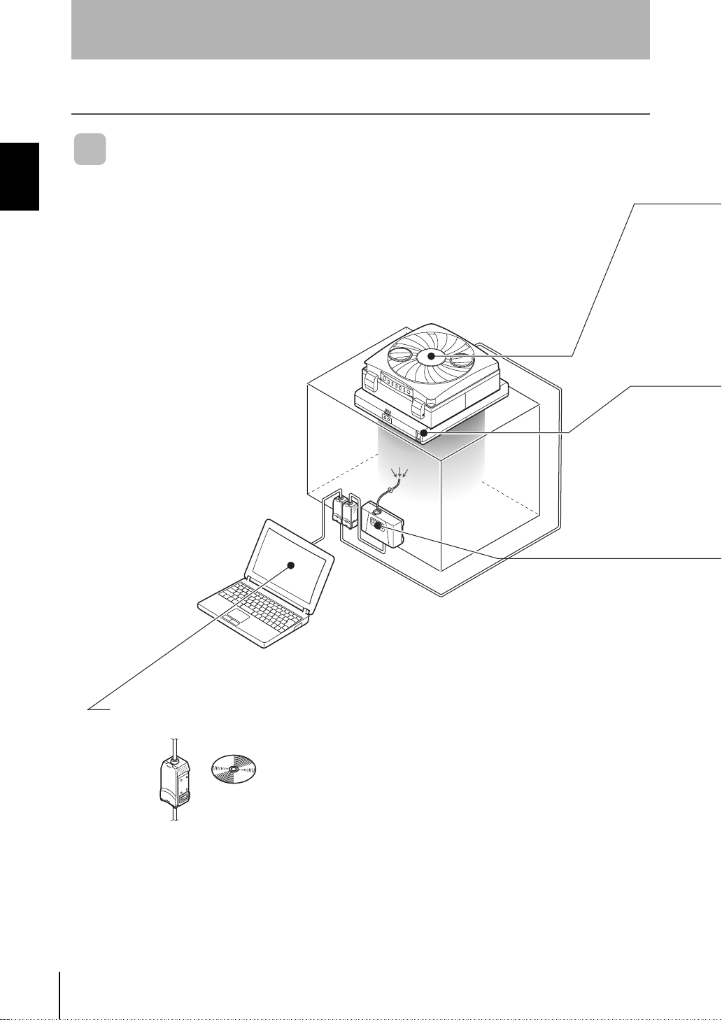
The clean sensing system continuously s enses the amount of particles
in a clean boot h or cl ean b ench, and c ontrols the ai r vol ume le ve l of t he
Air Clean Unit. This way, it can easily ensure an environment having a
fixed cleanliness class at all times.
An environment for removing dust and neu tralizing static electri city can
be built by incorporating a new-concept Ionizer Unit in this system.
What is the "Clean Sensing System?"
What is the "Clean Sensing System?"
Section 1 FEATURES
System Features
OPE3
OPE2
OPE1
Z
N
S
F
12
ZN
System Manu al
2
Page 13
What is the "Clean Sensing System?"
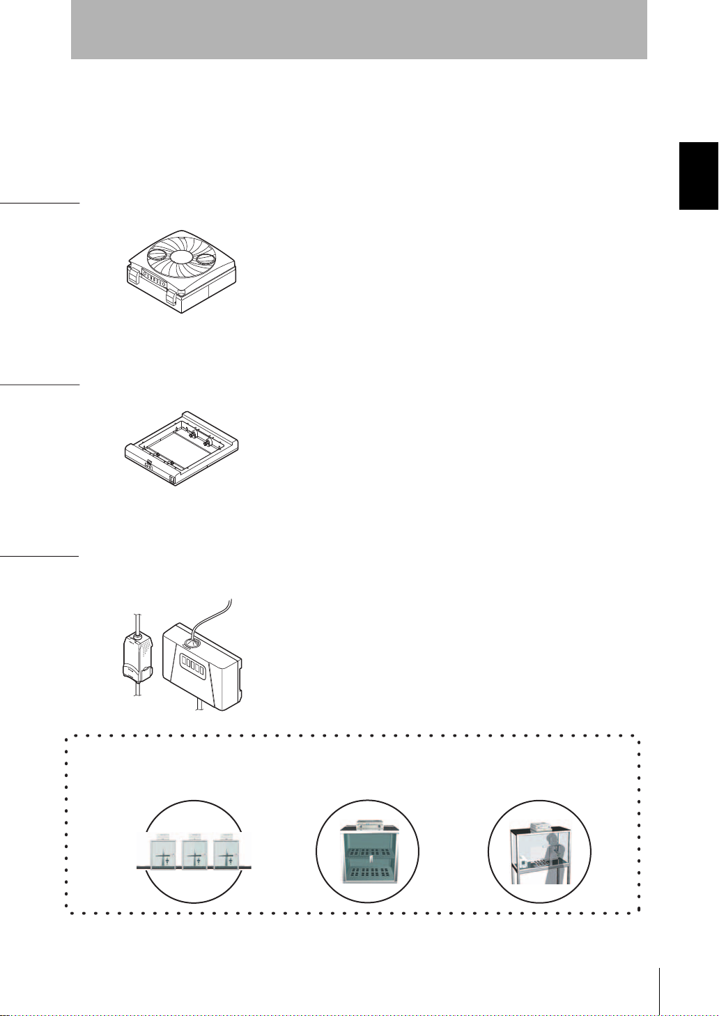
■ Air Clean Unit (ZN-A Series)
Unique twin-blower structure (ZN-A2502) achieves light weight
and large air volume.
Compact but more powerful.
Incorporating a clogged main filter (HEPA) detection function.
Visibility is improved by indicators located on two corners of
the body.
■ Air Particle Sensor (ZN-PD Series)
High-performance fan used for air suction to ensure
measurement at all times.
Use of a semiconductor laser and high-sensitivity optical
design in the sensor achieves measurement of minute
particles of 0.3 µm, 0.5 µm and 1.0 µm in diameter.
Thinnest in industry, large air volume
■ Ionizer Unit (ZN-J Series)
Directly mounted on Air Clean Unit
Open structure does not b lock the laminar ai rflow from the Ai r
Clean Unit.
No more troublesome wiring required. Installation man-hours
can be considerably reduced.
An industry first, one-touch dust removal and static neutralization
Smallest in industry, constant measuring
Main Applications
Electronic component
production processes
Storage or test
environments
Cell manufacturing
processes
Section 1
Section 1 FEATURES
System Manu al
ZN
3
Page 14
Section 1
What is the "Clean Sensing System?"
Features of the Clean Sensing System
Section 1 FEATURES
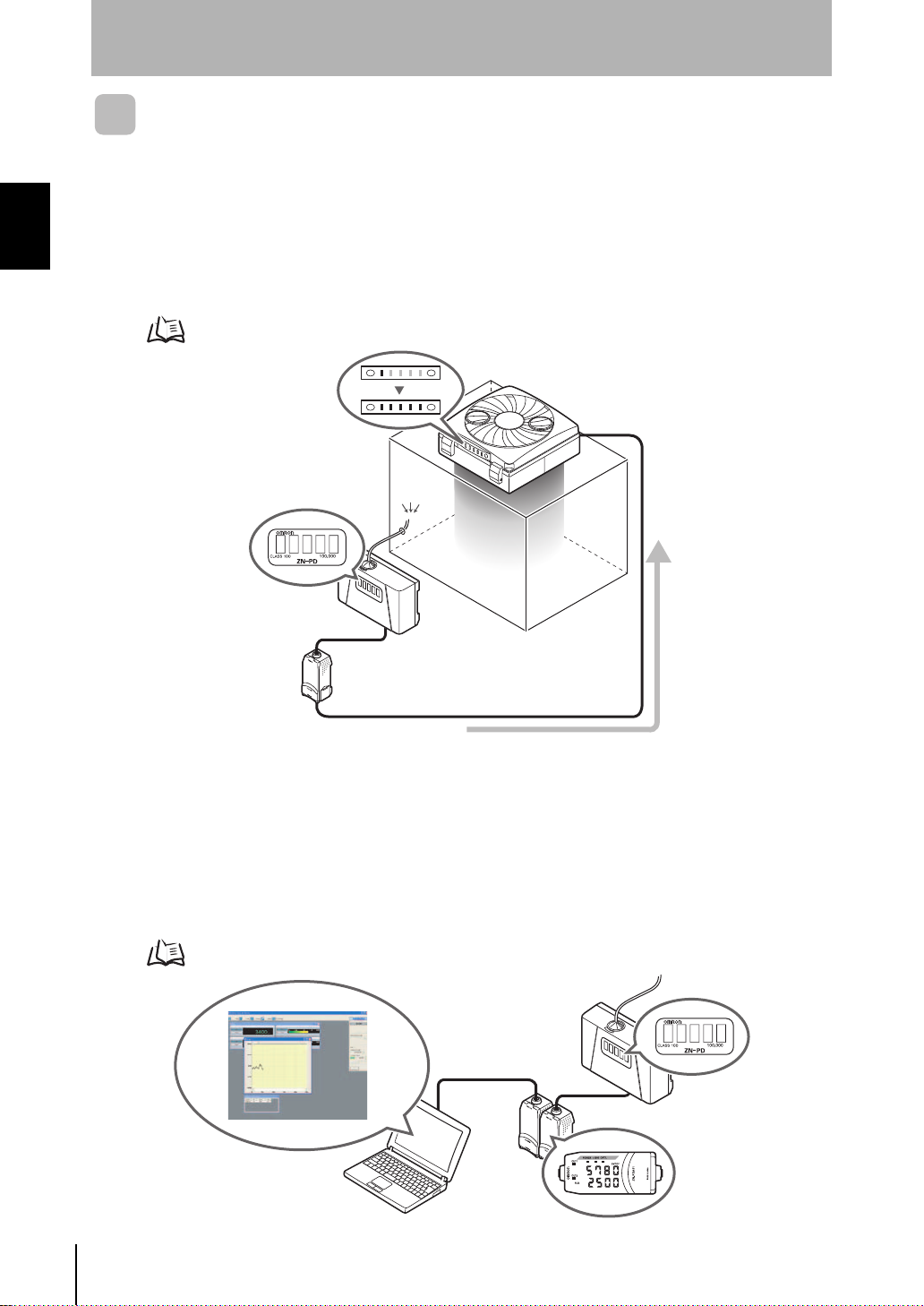
■ Feedback-based Automatic Adjustment of Air Volume
The air volume level of the Air Clean Unit can be automati cally controlled based on the
amount of particles measured by the Air Par ticle Sensor. The cleanli ness class in clean
booths can be maintained at the opt imum air volume level in propor tion to the amount of
particles from rapid air feed through to fine air volume operation in the power saving mode.
Setting Method p.18
4
■ Monitoring/Logging the Amount of Particles
The cleanlines s class i nside clean b ooths can be ver ified and ascertained by the amount of particle s
per unit volume. The amount of particles can be verified on the Sensor and the Amplifier Unit.
Measured values can be easily logged on a personal computer using Interface Units and the
exclusive monitoring software (Realtime Clean Air Monitor). Changes in the amount of particles
over time observed in this way can be made use of as data for improving product quality.
Setting Method p.25
ZN
System Manu al
OPE3
OPE2
OPE1
Page 15
Section 1
Max. 9 units connected
Max. 10 units connected
What is the "Clean Sensing System?"
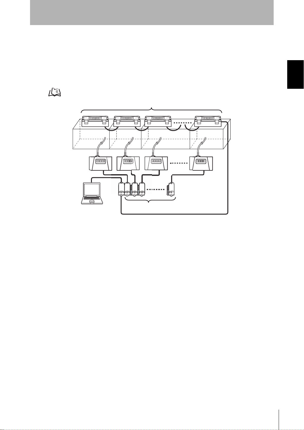
■ Improving Product Quality by Multi-point Measurement
Since Air Clean Units and Air Particle Sensors can be conn ected to each other, the
amount of air particles in multiple clean booths installed in processes can be
comprehensively de tected and controlled. Which process is worseni ng in cleanliness
can be linked to quality control for continual management.
Setting Method p.31
Section 1 FEATURES
System Manu al
ZN
5
Page 16
Section 1
Ion Balance Sensor
What is the "Clean Sensing System?"
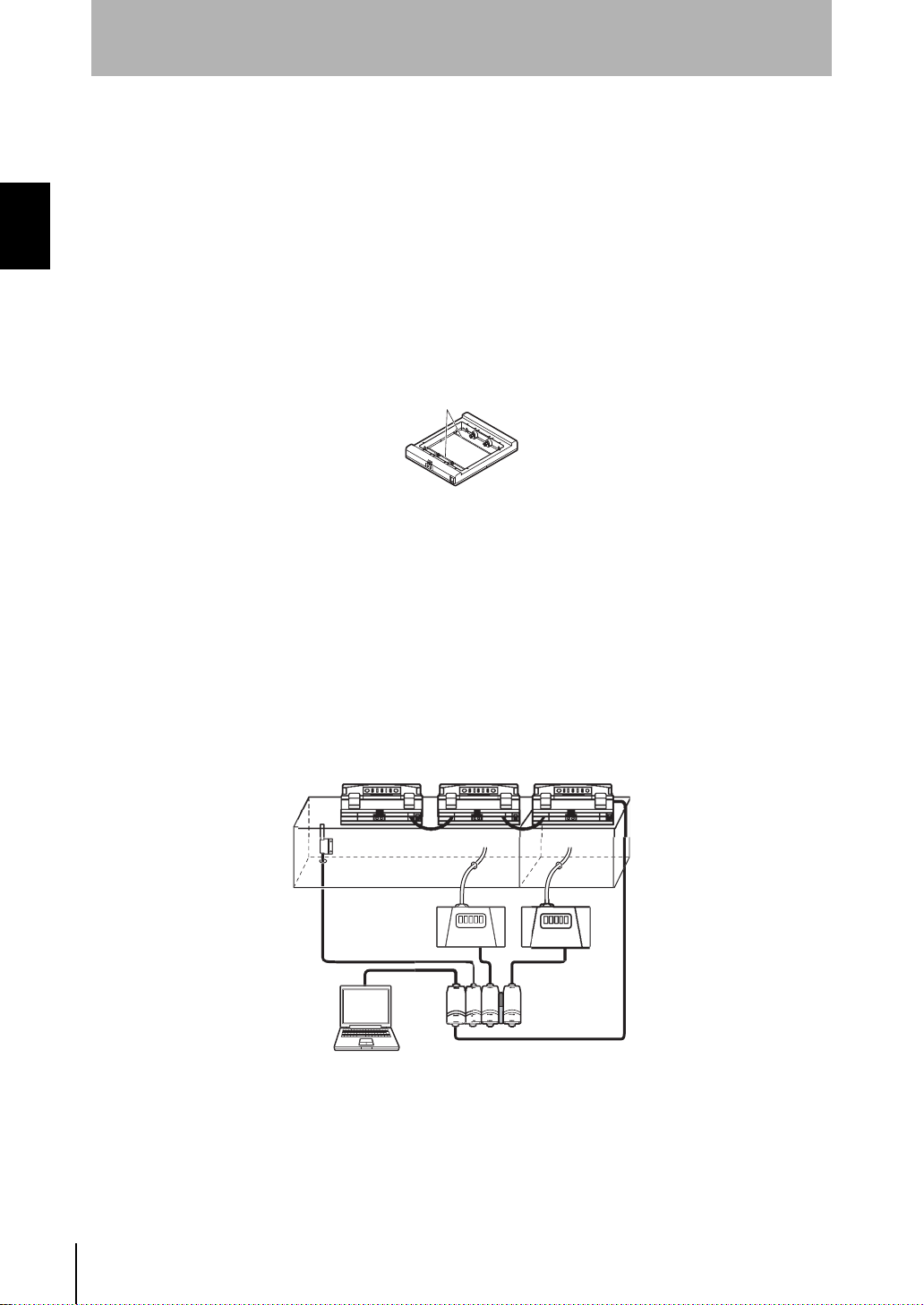
■ Simultaneous Dust Removal and Static Neutralization
The Ionizer Unit ZN-J series, the first in industry to be added on later to an Air Clean
Section 1 FEATURES
Unit, provides you with a new clean environment capable of removing dust and
neutralizing static electricity.
• Sim ultaneous Removal of Particles and Static Electricity
A variable DC sy stem is used for electrostatic di scharge. This system c an neutralize
static electricity in wide spaces.
Two ion balance sensors provide c onstant feedback to maintain uniform neutr alizing
performance.
• Simultaneous Monitoring of Charged Amount of Workpieces
Electrostatic Sensor ZJ-SD can be connected to the clean sensing system. The
problem of adhesion of particles can be solv ed by acc urately asc ertaining the char ged
amount of the workpiece, and using the Ionizer Unit to approp riately neutralize static
electricity.
Also, since ZJ-SD data can also b e cap tured on a person al c omputer via the Inte rfac e
Unit, the amount of particles and charged amount can be acquired and collected
simultaneously, and made use of as basic data for improving product quality.
ZN
System Manu al
6
Page 17
System Configuration Examples
S
For details on settings, see p.25.
System Configuration Examples
Section 1
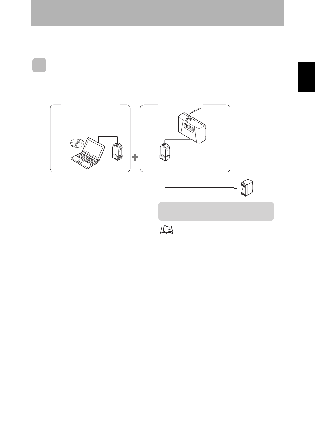
Direct Clean Sensing System
■ Data Logging
Clean Monitoring System
ZN-SFW11
Realtime
Clean Air Monitor
Interface
Unit
Z
N
S
F
1
1
Amplifier
Unit
Section 1 FEATURES
Air Particle Sensor
ensor
ZN-PD03
ZN-PDA11
DC power supply
[Features]
• Monitoring/Logging the Amount of Particles
System Manu al
7
ZN
Page 18
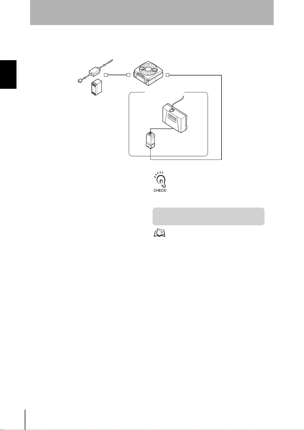
Section 1
S
r
A
For details on settings, see p.18.
To extend the cable mentioned above, a
commercially available LAN connector (female to
female, straight type) and a LAN cable (straight
type: Category 5E or higher) must be used.
System Configuration Examples
■ Feedback
Section 1 FEATURES
C adapter (provided)
Or, DC power supply
Air Clean Unit
ZN-A2502
ZN-A4105
Air Particle Sensor
enso
Amplifier
Unit
ZN-PD03
ZN-PDA12
Cable length: standard 2 m
[Features]
• Feedback-based Automatic Adjustment of Air Volume
ZN
System Manu al
8
Page 19
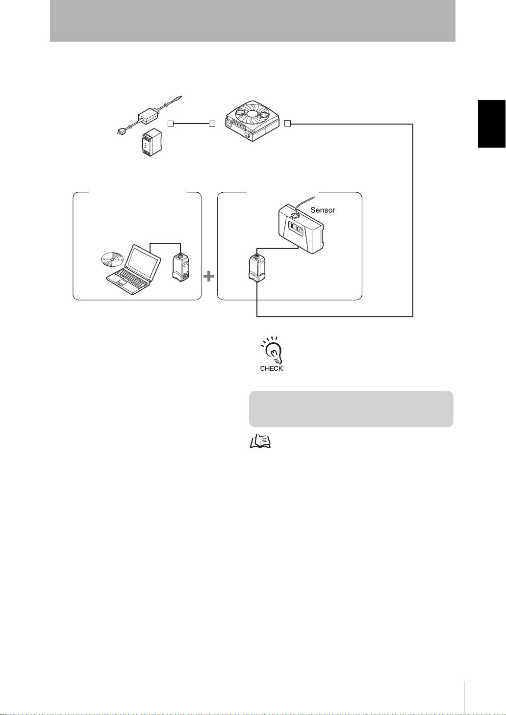
■ Feedback and Data Logging
Z
N
S
F
1
1
Air Clean Unit
ZN-A2502
ZN-A4105
[Features]
• Feedback-based Automatic Adjustment of Air Volume
• Monitoring/Logging the Amount of Particles
Air Particle Sensor
Interface
Unit
Realtime
Clean Air Monitor
ZN-PD03
Amplifier
Unit
ZN-PDA12
Clean Monitoring System
ZN-SFW11
AC adapter (provided)
Or, DC power supply
Cable length: standard 2 m
For details on settings, see p.18, p.25.
To extend the cable mentioned above, a
commercially available LAN connector (female to
female, straight type) and a LAN cable (straight
type: Category 5E or higher) must be used.
Section 1
System Configuration Examples
Section 1 FEATURES
System Manu al
ZN
9
Page 20
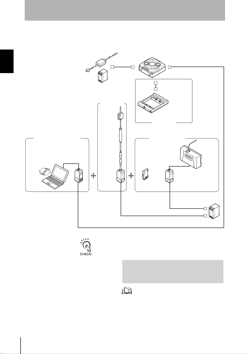
Section 1
For details on settings, see p.18, p.25.
To extend the cable mentioned above, a commercially available LAN
connector (female to female, straight type) and a LAN cable (straight type:
Category 5E or higher) must be used.
System Configuration Examples
■ Dust Removal and Static Neutralization
Connection Example with Different Models (Electrostatic Sensor)
Section 1 FEATURES
Air Clean Unit
AC adapter (provided)
Or, DC power supply
ZN-A2502
ZN-A4105
Connector cable
(provided)
Clean Monitoring System
Realtime
Clean Air Monitor
Electrostatic
Sensor
ZJ-SD100
ZN-SFW12
Interface
Unit
OPE3
OPE2
OPE1
ZN
SF
1
2
Amplifier
Unit
ZJ-SDA11
Cable length: standard 2 m
Sensor
ZN-J25A
ZN-J41A
Ionizer Unit
Air Particle Sensor
Sensor
ZX-CAL2
Amplifier
Unit
ZN-PD03
ZN-PDA11
Calculating
Unit
OPE3
OPE2
OPE1
ZERO ENABLE
(kV)
Z
J
-S
D
A
1
1
DC power
supply
10
ZN
System Manu al
[Features]
• Simultaneous Monitoring of the Ion Balance
• Feedback-based Automatic Adjustment of Air Volume
• Monitoring/Logging the Amount of Particles
Page 21
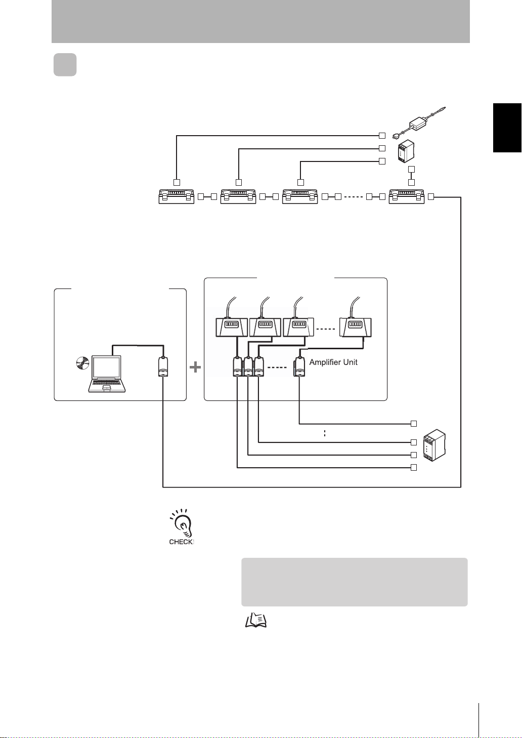
ZN-A2502
ZN-A4105
Air Clean Unit
Air Particle Sensor
Calculating Unit
ZX-CAL2
ZN-PD03
Sensor
ace
Unit
e
r
ZN-SFW12
Clean Monitoring System
Commercially available LAN cable
(straight type: Category 5E or higher)
DC power
supply
[Features]
• Feedback-based Automatic Adjustment of Air Volume
• Monitoring/Logging the Amount of Particles
• Detecting the Cleanliness of Multiple Processes
AC adapter
(provided)
Or,
DC power supply
Cable length: standard 2 m
For details on settings, see p.31.
To extend the cable mentioned above, a commercially available LAN
connector (female to female, straight type) and a LAN cable (straight type:
Category 5E or higher) must be used.
Realtim
Clean Air Monito
Multi-Clean Sensing System
Interf
Section 1
System Configuration Examples
Section 1 FEATURES
-
System Manu al
ZN
11
Page 22

Section 1
System Configuration Examples
MEMO
Section 1 FEATURES
12
ZN
System Manu al
Page 23
Section 2
UPGRADING THE SYSTEM
Before Upgrading the System 14
Flow of Operations for Upgrading the System 14
Installing the Exclusive Monitoring Software 15
Setup Methods Suited to Specific Applications 18
Automatically Adjusting the Air Volume Level 18
Monitoring/Logging the Amount of Particles 25
Detecting the Cleanliness of Multiple Processes 31
Section 2 UPGRADING THE SYSTEM
System Manu al
ZN
13
Page 24
Section 2
p.18 p.25 p.31
p.48
Before Upgrading the System
Before Upgrading the System
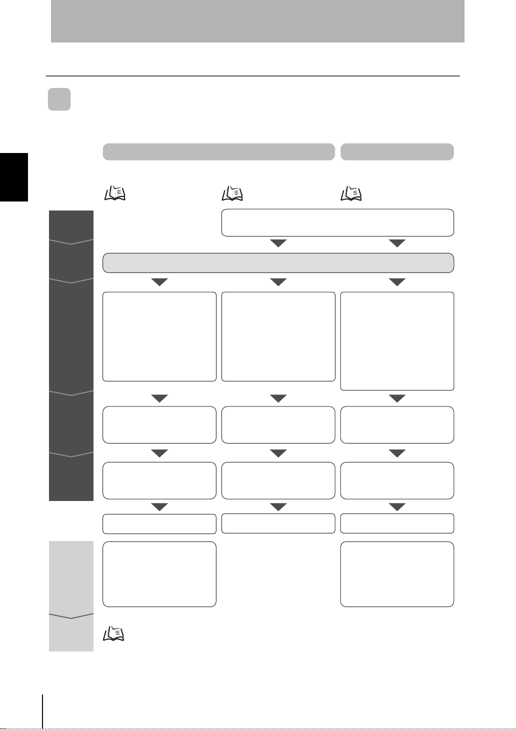
Flow of Operations for Upgrading the System
Section 2 UPGRADING THE SYSTEM
Preparation
Installation
Connections
Checks
Direct Clean Sensing System
Automatically Adjusting
the Air Volume Level
Refer to the Instruction Sheet packaged with each device.
• Setting the ID of the Air Clean
Unit
• Connecting the Air Clean Unit
and Air Particle Sensor
• Connecting the Air Clean Unit
power supply
Checking communications Checking system operation Checking system operation
Monitoring/Logging
the Amount of Particles
Installing the exclusive monitoring software
• Connecting the Air Particle
Sensor and Interface Unit
together
• Connecting the Interface Unit
and personal computer
• Connecting the Air Particle
Sensor power supply
Multi-Clean Sensing System
Detecting the Cleanliness of
Multiple Processes
• Setting the ID of the Air Clean Unit
• Connecting the Air Clean Unit
and Interface Unit
Connecting Air Clean Units to each other
•
• Connecting the Air Particle Sensor
and Interface Unit together
• Connecting the Interface Unit
and personal computer
• Connecting the Air Particle
Sensor power supply
Connecting the Air Clean Unit power supply
•
14
Operations
and settings
Resetting
during
operation
Maintenance
ZN
System Manu al
Setting the feedback conditions
Starting operation
• Resetting the feedback method
Resetting the target cleanliness class
•
• Resetting the feedback cycle
Resetting the low power air volume level
•
•
Resetting the high power air volume level
• Resetting the high power time
Trend graph display/data logging
Starting monitoring/logging Starting operation
Setting the feedback conditions
• Resetting the feedback method
Resetting the target cleanliness class
•
• Resetting the feedback cycle
Resetting the low power air volume level
•
• Resetting the calculation type
Resetting the high power air volume level
•
• Resetting the high power time
Page 25

Section 2
Clean Monitoring System
(ZN-SFW11/SFW12)
Realtime
Clean Air Monitor
Interface Unit
Numerical display of measured
amount of particles
Graphic display of changes in
measured values over time
Logging of data
Display and setting of Air Particle Sensor and Interface Unit settings
Before Upgrading the System
Installing the Exclusive Monitoring Software
The Exclusive Monitoring Software (Realtime Clean Air Monitor) tool is provided for the
ZN Series. This tool allows you to set sensing functions, acquire and collect the amount
of measured particles, and display this information as a graph on a personal computer.
ZN-SF12
• Monitoring of measurement results
Section 2 UPGRADING THE SYSTEM
• Function setup support
■ Operating Environment
The following operating environment for Exclusive Monitoring Software is
recommended. Check the environment before installing the software.
Item Condition
OS Windows 2000/XP
CPU PentiumIII 850 MHz or faster (2 GHz or faster recommended)
RAM 128 MB or more (256 MB or more recommended)
Free space on hard disk At least 50 MB
Display screen 1024 x 768 dots
High Color (16-dot) or higher
• Windows is a trademark or registered trademark of Microsoft Corporation.
System Manu al
ZN
15
Page 26

Section 2 UPGRADING THE SYSTEM
Section 2
Before Upgrading the System
■ How to Install/Uninstall the Software
The following describes the preparations for using Exclusive Monitoring Software.
• Installing Exclusive Monitoring Software
Before you install the software, quit all other programs that are running. Also, note that
installation may take a long time if antivirus software is installed on the personal
computer.
Log on as an Admin istrator or a us er, such as a computer adm inistrator, having rights
to change system settings.
1. Turn the personal computer's power supply ON to start up Windows.
2. Insert the "Exclusive Mo nitoring Software" CD- ROM into the CD-R OM drive on
the personal computer.
3. The program is launch ed autom aticall y and the in stallatio n screen is display ed.
Follow the on-screen instructions to install the software.
If the installation is not automatically started, execute "setup.exe" in the CD-ROM.
• Uninstalling Exclusive Monitoring Software
Before you uninstall the software, quit al l other programs that are running. A lso, note
that uninstallation may take a lon g time if antivirus software is installed on the per so nal
computer.
Log on as an Admin istrator or a us er, such as a computer adm inistrator, having rights
to change system settings.
1. Turn the personal computer's power supply ON to start up Windows.
2. Select [Settings]-[Control Panel] from the [Start] menu of your personal
computer.
3. Double-click [Add/Remove Programs].
4. Select [Realtime Clean Air Monitor] from the list, and click the [Change/Remove]
button.
5. Click [OK].
16
ZN
System Manu al
Page 27
Section 2
Side with no tab
Before Upgrading the System
■ Starting Up the Exclusive Monitoring Software
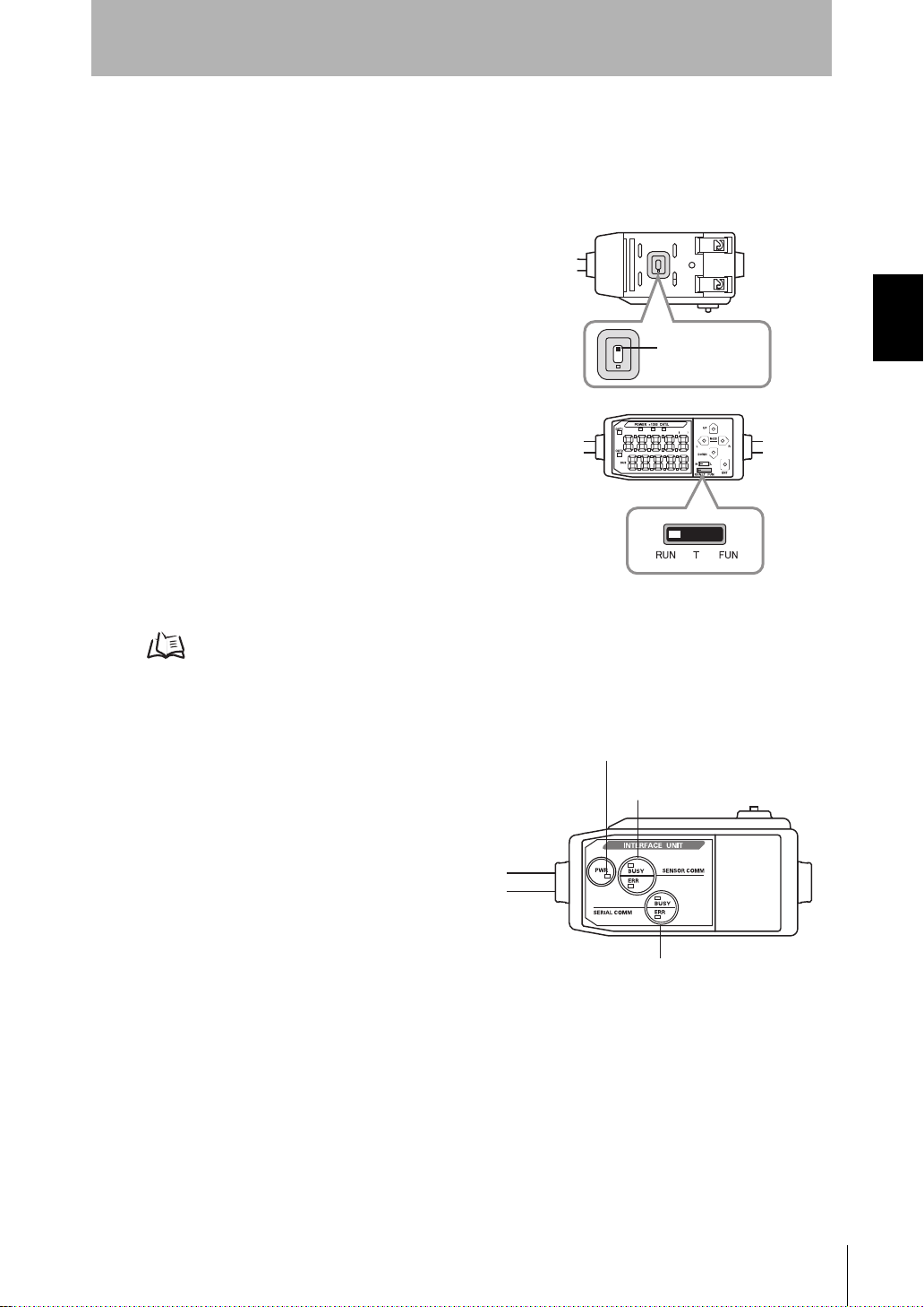
After installation is completed, start up E xclusive Monitoring S oftware by t he followin g
procedure.
1. Check that the current/voltage switc h on the
base of the Interface Unit is set to the side
that has no tab (default).
Section 2 UPGRADING THE SYSTEM
2. Set the Air Particle Sensor Amplifier Unit to
the RUN mode.
CNT/CF
3. Connect the Interface Unit to the personal computer.
To connect to a personal computer (PC/AT compatible), use a 9-pin D-sub cross cable (female to female).
p.64
4. Connect the Interface Unit to the Amplifier Unit.
5.
Turn the power supply of each device ON.
On the ZN-SF11, the ERR indicators for the sensor
communications indicator and external terminal
communications indicator go out.
On the ZN-SF12, the model indication when it is
started up goes out, and the indication changes to
the normal display (measured value display, etc.).
The Interface Unit is now ready for communications.
Power indicator
Sensor communication
indicator (BUSY/ERR)
External terminal communication
indicator (BUSY/ERR)
6.
Start up the exclusive monitoring software.
Communications is automatically started.
■ Exiting the Exclusive Monitoring Software
Exit Exclusive Monitoring Software by the following procedure.
1. Select [File]-[Close] from the Exclusive Monitoring Software menu bar.
System Manu al
ZN
17
Page 28
Section 2 UPGRADING THE SYSTEM
1. Setting the ID of the Air Clean
Unit
2. Connecting peripheral devices
3. Checking communications
4. Setting the feedback conditions
p.18
p.19
p.19
p.20
4-1. Rapid feedback
4-2.
Constant feedback
p.23
Section 2
Setup Methods Suited to Specific Applications
Setup Methods Suited to Specific Applications
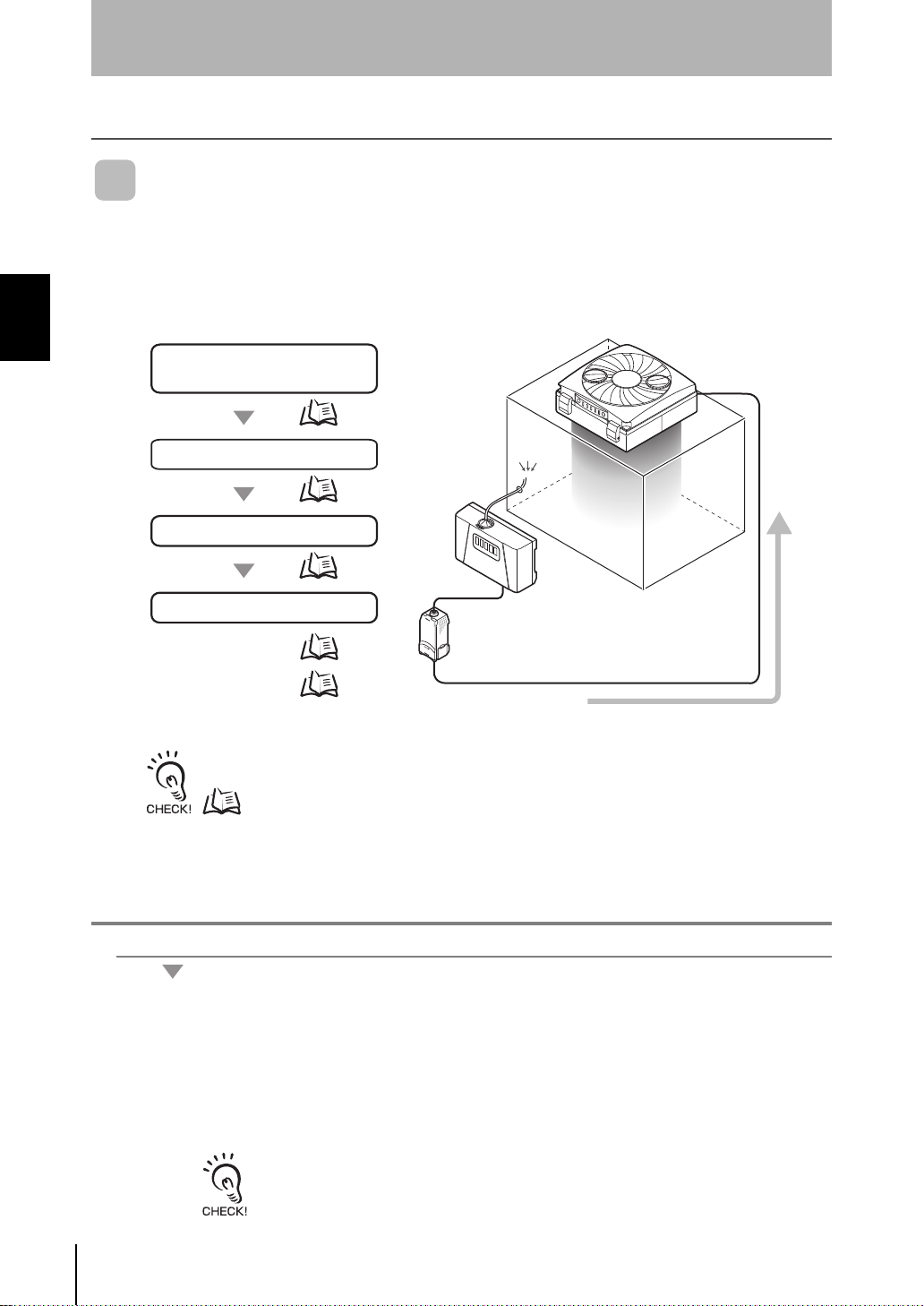
Automatically Adjusting the Air Volume Level
Feedback control is perfor med between the Air Particle Sensor an d Air Clean Unit to
feed in highly clean air (i.e. air containing little dust).
The following describes an exam ple where the air vo lume le vel of the Air Cle an Unit is
automatically adjusted.
To use multiple Air Particle Sensors or multiple Air Clean Units to apply feedback on the control
loop, configure a multi-clean sensing system using the Interface Unit (ZN-SF12).
1. Setting the ID of the Air Clean Unit
ZN
System Manu al
18
1. Set DIP switch SW1 on the rear of the Air Clean Unit to ON (external
communications control enabled).
2. Set the ID rotary switch on the rear of the Air Clean Unit to 0 (0ch).
p.11
The ID rotary switch must always be set to "0" (0ch) when using the Air Particle Sensor
(ZN-PDA12). Feedback communications cannot be performed when the ID is set to
other than "0" (0ch).
Page 29
Section 2
Setup Methods Suited to Specific Applications
2. Connecting peripheral devices
Connect the Air Clean Unit to the Air Particle Sensor to supply power to the Air Clean Unit.
System Configuration Examples p.8
3. Checking communications
Check that communications between the units is being performed correctly by manually switching the air
volume level of the Air Clean Unit on the Air Particle Sensor.
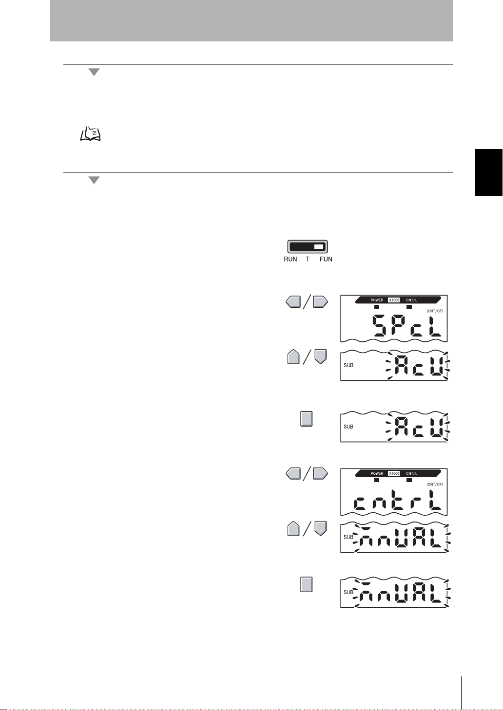
1. Set the mode switch of the Ai r Parti cl e
Sensor Amplifier Unit to the FUN
mode.
2. Display [SPCL] on the main display.
Section 2 UPGRADING THE SYSTEM
3. Display [ACU] on the sub-display.
4. Press the ENT key.
5. Display [CNTRL] on the main display.
6. Select [MNUAL].
(default value: MANUAL)
7. Press the ENT key.
This sets the selected mode.
System Manu al
ZN
19
Page 30
Section 2 UPGRADING THE SYSTEM
Section 2
Setup Methods Suited to Specific Applications
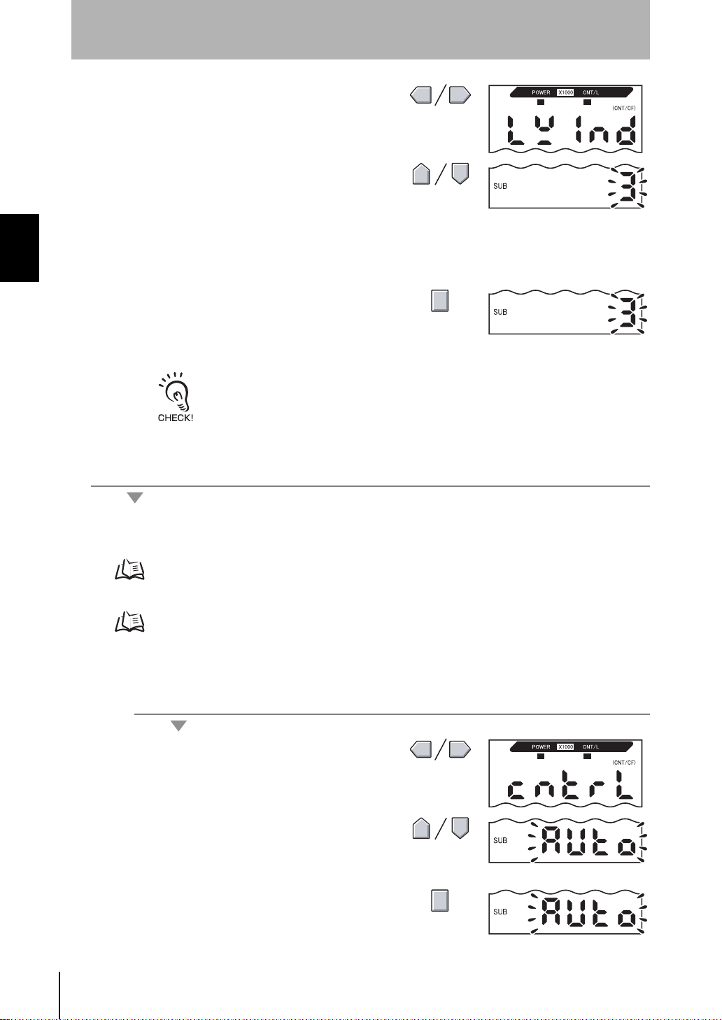
8. Display [LWIND] on the main display.
9. Set the air volume level of the Air
Clean Unit.
Set the desired air volume level, and check that
the air volume level is changed. (range: 1 to 5,
default value: 1)
10. Press the ENT key.
Check the air volume level of the Air Clean Unit.
If the air volume changes, this indicates that
communications is being performed normally.
If the air volume does not change:
Check the Air Clean Unit settings, Air Particle Sensor operation, and the wiring of
connected cables.
When the Air Clean Unit settings have been changed, turn the power supply OFF and
then back ON to enable the settings.
4. Setting the feedback conditions
Set the feedback conditions for the Air Clean Unit.
There are two feedback methods, and each of their setup methods is different.
Rapid feedback p.20
Constant feedback p.23
For details on feedback operation and setup parameters, see "Feedback Methods."
p.38
4-1. Rapid feedback
Set this method to quickly improve the environment when a drop in cleanliness is detected.
Selecting the air volume level control method
1. Display [CNTRL] on the main display.
Set the method for controlling the air volume
level control of the Air Clean Unit.
2. Select [AUTO].
Set air volume level control of the Air Clean Unit
to automatic.
3. Press the ENT key.
This sets the selected mode.
20
ZN
System Manu al
Page 31
Setup Methods Suited to Specific Applications
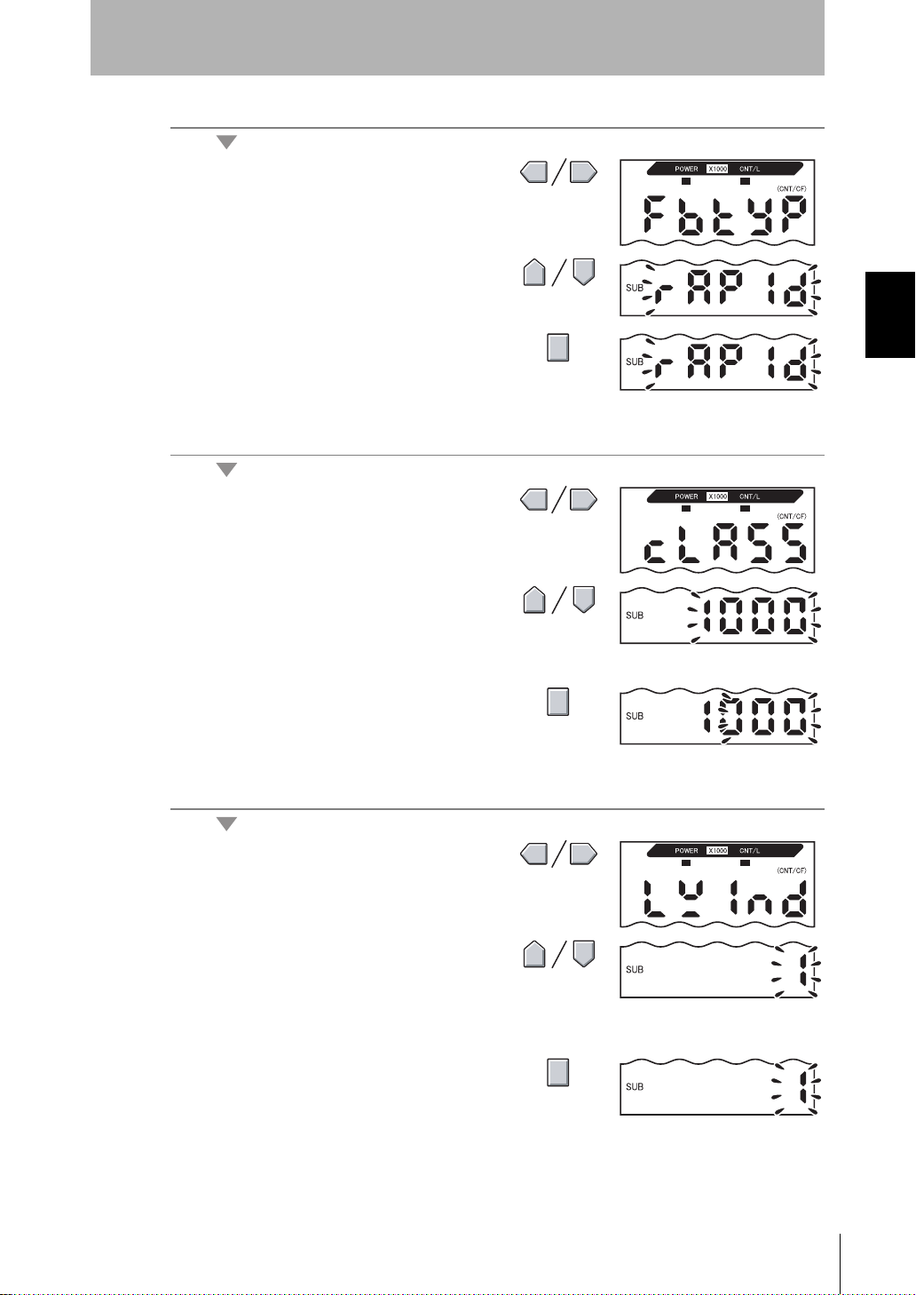
Selecting the feedback method
4. Display [FBTYP] on the main display.
Set the feedback method.
Section 2
5. Display [RAPID] on the sub-display.
6. Press the ENT key.
This sets the rapid feedback method.
Setting the target cleanliness
7. Display [CLASS] on the main display.
8. Select the target cleanliness class.
9. Press the ENT key.
This sets the specified target value.
Section 2 UPGRADING THE SYSTEM
Setting the low power air volume level
10. Display [LWIND] on the main display.
11. Set the low power air volume level of
the Air Clean Unit.
Set the air volume level for when the target
cleanliness is satisfied.
12. Press the ENT key.
This sets the specified air volume level.
System Manu al
ZN
21
Page 32

Section 2
Setup Methods Suited to Specific Applications
Setting the high power air volume level
13. Display [HWIND] on the main display.
Section 2 UPGRADING THE SYSTEM
14. Set the high power air volum e level of
the Air Clean Unit.
Set the air volume level within 1 to 5 (default value: 5).
Set the air volume level for when the target
cleanliness is not satisfied.
For the high power air volume level, always set an air volume greater than the low power
air volume level.
Feedback will not function properly if a smaller value is set.
15. Press the ENT key.
This sets the specified air volume level.
Setting the high power time
16. Display [HTIME] on the main display.
Set the high power time.
17.
Set the high po wer time of th e A ir C lea n U nit.
Set the time (s) within 0 to 999 (default value: 60).
Set the time that the high power air volume level
is to be held for.
22
18. Press the ENT key.
This sets the specified time.
The time that the high power air volume level is actually held is an integer multiple of the
feedback cycle (i.e. measurement cycle).
Example:
Measurement cycle: 60 s
When the high power time is set to "100 s", the actual high power time is 120 s.
19. Set the mode switch to RUN.
This starts feedback control operation.
When the setting is next used, feedback is automatically started simply by turning the Air
Clean Unit power supply ON.
ZN
System Manu al
Page 33
Setup Methods Suited to Specific Applications
4-2. Constant feedback
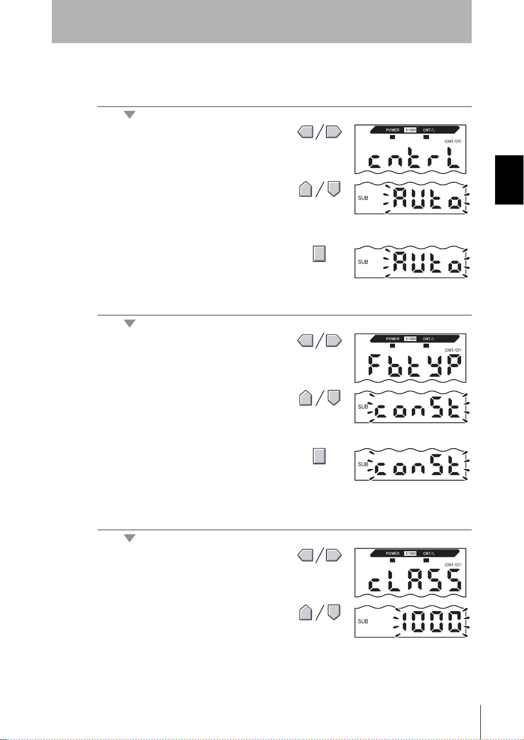
Set this method to stabilize cleanliness in the booth (area) at all times.
Selecting the air volume level control method
1. Display [CNTRL] on the main display.
2. Select [AUTO].
Set air volume level control of the Air Clean Unit
to automatic.
3. Press the ENT key.
This sets the selected mode.
Selecting the feedback method
Section 2
Section 2 UPGRADING THE SYSTEM
4. Display [FBTYP] on the main display.
Set the feedback method.
5. Display [CONST] on the sub-display.
6. Press the ENT key.
This sets the constant feedback method.
Setting the target cleanliness
7. Display [CLASS] on the main display.
8. Select the target cleanliness class.
System Manu al
ZN
23
Page 34
Section 2
Setup Methods Suited to Specific Applications
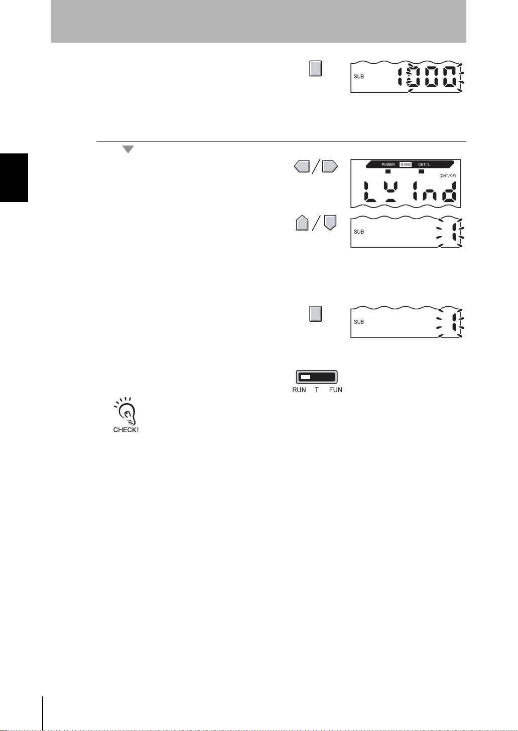
9. Press the ENT key.
This sets the specified target value.
Setting the low power air volume level
Section 2 UPGRADING THE SYSTEM
10. Display [LWIND] on the main display.
11. Set the low power air volume level of
the Air Clean Unit.
Set the air volume level within 1 to 5 (default
value: 1).
Set a limit value for the air volume beyond which
air is not to be fed.
12. Press the ENT key.
This sets the specified air volume level.
13. Set the mode switch to RUN.
This starts feedback control operation.
When the setting is next used, feedback is automatically started simply by turning the Air
Clean Unit power supply ON.
24
ZN
System Manu al
Page 35
Section 2
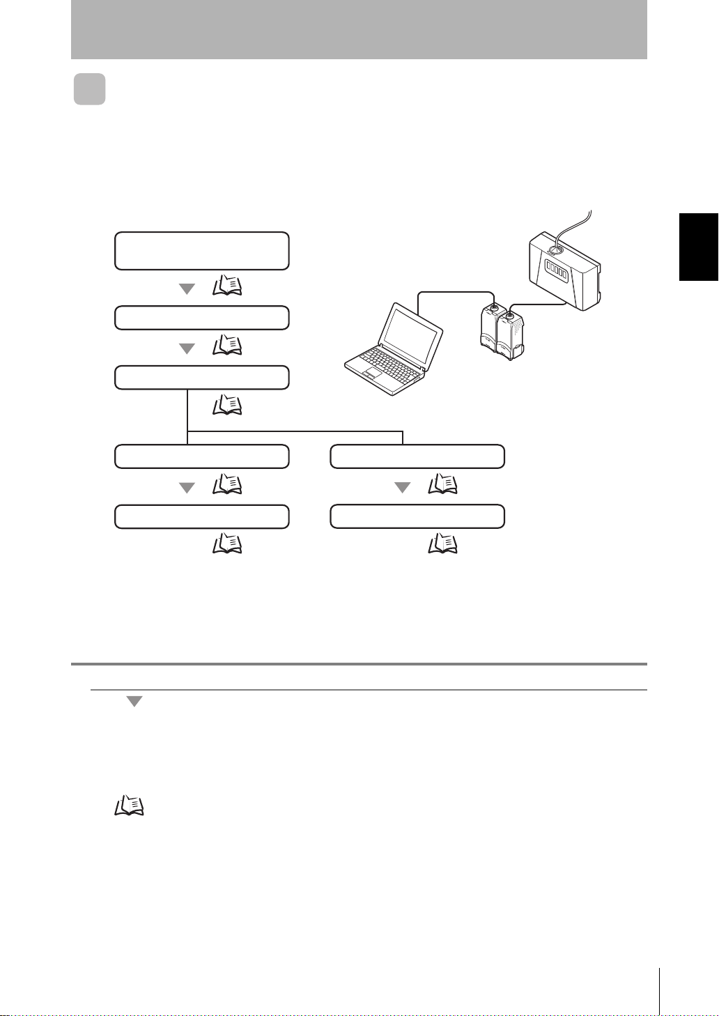
3. Checking system operation
p.26
p.26
4-1. Displaying trend graphs
1. Installing the Exclusive
Monitoring Software
p.27
5-1. Starting monitoring
p.28
p.25
2. Connecting peripheral devices
4-2. Data logging
p.29
5-2. Starting logging
p.30
Setup Methods Suited to Specific Applications
Monitoring/Logging the Amount of Particles
Measured particle values can be easily c aptured on a personal computer by using a n
Interface Unit (sold separately) and the Exclusive Monitoring Software.
The following describe s an example where the amount of particles is displ ayed as a
trend graph and is saved as data.
OPE3
OPE2
OPE1
Section 2 UPGRADING THE SYSTEM
1. Installing the Exclusive Monitoring Software
Install the software (exclusive monitoring software) on the personal computer beforehand.
Installing the Exclusive Monitoring Software p.15
System Manu al
ZN
25
Page 36
Section 2 UPGRADING THE SYSTEM
Section 2
Setup Methods Suited to Specific Applications
2. Connecting peripheral devices
Connect the Air Clean Unit, Air Particle Sensor, Interface Unit, and the personal computer, and turn the
power supply of all of these devices ON.
Before connecting these devices, turn their power supplies OFF.
System Configuration Examples p.7, p.9
3. Checking system operation
Make sure that the Air Particle Sensor and Interface Unit have started up normally.
• W hen the Air Particle Sensor has not started up normally:
Check the Sensor connection. Also, refer to the Instruction Sheet for the Air Particle Sensor in the
case of other errors.
• W hen the Interface Unit has not started up normally:
Make sure that the Air Particle Sensor Amplifier Unit is in the RUN mode. Also, check the
connections of the peripheral devices.
26
ZN
System Manu al
Page 37

4-1.Displaying trend graphs
Select the number of planes to draw graphs in.
Single:All channels to be drawn as a waveform are
drawn in a single graph plane.
Multi: One waveform is drawn in one graph plane.
Select the type of the graph.
Line Chart: Displays the minimum and maximum
values within a specific time period.
Color Chart: The current value is displayed color-coded.
Select the channel No. to be drawn as a waveform.
Single CH:Select this item to draw only a specific
channel No.
Multi CH: Select this item to draw multiple channel Nos.
simultaneously.
CH No.: Select the channel No. to be drawn.
Up to five waveforms can be drawn
simultaneously.
Select the particle size to be drawn as a waveform.
Display the amount of particles as a trend graph.
1. Start up Exclusive Monitoring Software.
Starting Up the Exclusive Monitoring Software p.17
2. Click the [Graph] button and then [Edit graph ] button to display the Edit Graph
screen.
Section 2
Setup Methods Suited to Specific Applications
Section 2 UPGRADING THE SYSTEM
3. In the Edit Graph screen, set the graph drawing conditions.
System Manu al
ZN
27
Page 38

Section 2 UPGRADING THE SYSTEM
Sets the scale of the vertical axis.
Sets the value at the center of the vertical scale.
Sets the vertical axis to a scale that allows all
waveforms to be displayed.
Sets the scale of the horizontal axis.
Section 2
Setup Methods Suited to Specific Applications
4. Click the [Set] button.
5. Align the scales of the horizontal and vertical axes.
5-1.Starting monitoring
Click the [START] button to start drawing the graph.
To stop drawing the graph, click the [STOP] button.
ZN
System Manu al
28
To save waveform data, click the [Save Waveform] button. (Data is saved in CSV format.)
The data for up to five planes including past data can be saved.
Page 39
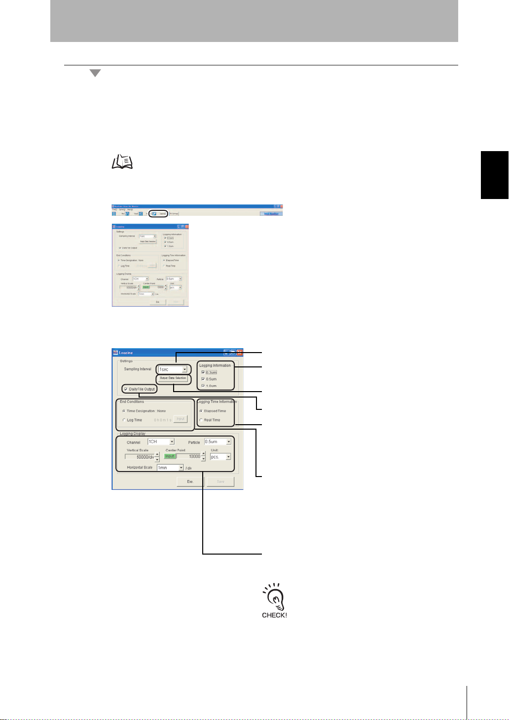
4-2.Data logging
Select the time data display method that is saved at the
same time as the data when performing logging.
Elapsed Time:The elapsed time is saved as the data
starting from the logging start time.
Real Time: The actual time is saved as data.
Select the particle size to be saved.
(Multiple selections are allowed.)
Select the channel and particle size to be drawn during
logging. Also, set the horizontal and vertical scales,
center of the vertical axis, and the display unit.
[Center Point] can be set directly by clicking
the [Input] button and entering a value.
The unit selected at [Unit] is also reflected in
the unit in the graph plane.
Select the sampling interval at which data is to be logged.
Click the [Output Data Selection] button to select the channel
to output data from in the output channel selection screen.
Select the logging end conditions.
Time Designation: None:
Logging is continued until it is
ended manually.
Log Time: Set the time up to when logging
ends after the [Input] button is
clicked. When the time set here has
elapsed, logging automatically ends.
(A time up to 24 hours can be set.)
When this item is selected, a logging file is
automatically created and saved at each new day.
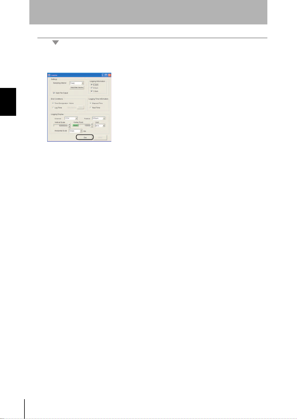
Data logging saves the trends for the amount of particles in a clean booth as data.
1. Start up the Exclusive Monitoring Software.
2. Click the [Logging] button to display the Logging screen.
Section 2
Setup Methods Suited to Specific Applications
Section 2 UPGRADING THE SYSTEM
Starting Up the Exclusive Monitoring Software p.17
3. In the Logging screen, set the logging conditions.
System Manu al
ZN
29
Page 40
Section 2 UPGRADING THE SYSTEM
Section 2
Setup Methods Suited to Specific Applications
5-2.Starting logging
Click the [Exe.] button to start Logging.
30
ZN
System Manu al
Page 41
Section 2
4. Checking system operation
p.32
p.32
5. Setting the feedback conditions
1. Installing the Exclusive
Monitoring Software
p.32
p.31
3. Connecting peripheral devices
p.32
2. Setting the ID of the Air
Clean Unit
n units connected
m units connected
n: max. 9 units
m: max. 10 units
1ch2chnch 3ch
1ch2ch3chmch
Setup Methods Suited to Specific Applications
Detecting the Cleanliness of Multiple Processes
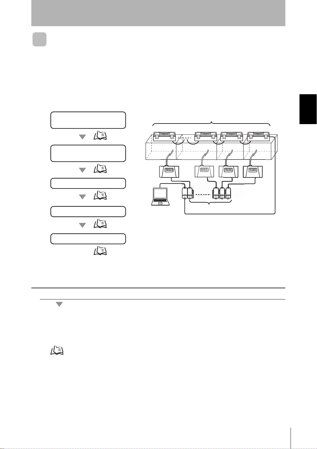
The cleanliness of multiple processes can be verified a t each individual process by
multiple Air Particle Sensors and multiple Air Clean Units. The air volume level also can
be controlled on individual equipment or booth (area).
The following describes an example where the cleanliness of multiple processes is
controlled.
Section 2 UPGRADING THE SYSTEM
1. Installing the Exclusive Monitoring Software
Install the software (exclusive monitoring software) on the personal computer beforehand.
Installing the Exclusive Monitoring Software p.15
System Manu al
ZN
31
Page 42
Section 2 UPGRADING THE SYSTEM
Section 2
Setup Methods Suited to Specific Applications
2. Setting the ID of the Air Clean Unit
1. Set DIP switch SW1 on the rear of the Air Clean Unit to ON (external
communications control enabled).
2. Set each of the channels (1 to n) by the ID rotary switch on the rear of the Air
Clean Unit.
Be sure to set unique ID numbers to each Unit.
The Units will not function properly when the same ID is set to multiple units.
When using the ZN-SF12 to perform feedback control, do not set the ID number to "0" (0ch).
A ZN-SF12 set to 0ch cannot be controlled.
3. Connecting peripheral devices
Connect the Air Clean Unit, Air Particle Sensor, Interface Unit, and the personal computer, and turn the
power supply of all of these devices ON.
Before connecting these devices, turn their power supplies OFF.
System Configuration Examples p.11
4. Checking system operation
Check operation of the Air Clean Unit, Air Particle Sensor and Interface Unit.
• When the Air Particle Sensor has not started up normally:
Check the Sensor connection. Also, refer to the Instruction Sheet for the Air Particle Sensor in the
case of other errors.
• W hen the Interface Unit has not started up normally:
Make sure that the Air Particle Sensor Amplifier Unit is in the RUN mode. Also, check the
connections of the peripheral devices.
• Check that the Air Clean Unit is in the standby mode.
5. Setting the feedback conditions
Operate the Exclusive Monitoring Software to set multiple feedback conditions.
1. Start up Exclusive Monitoring Software.
32
Starting Up the Exclusive Monitoring Software p.17
ZN
System Manu al
Page 43

Section 2
Feedback destination Air Clean Unit:
Select the Air Clean Unit to be controlled.
Area selection:
Select the target area to be set.
Air Volume Level Control:
Select the method for controlling the air volume level.
Feedback source Sensor channel:
Select the Air Particle Sensors located in the target
areas.
Set the details.
Setup Methods Suited to Specific Applications
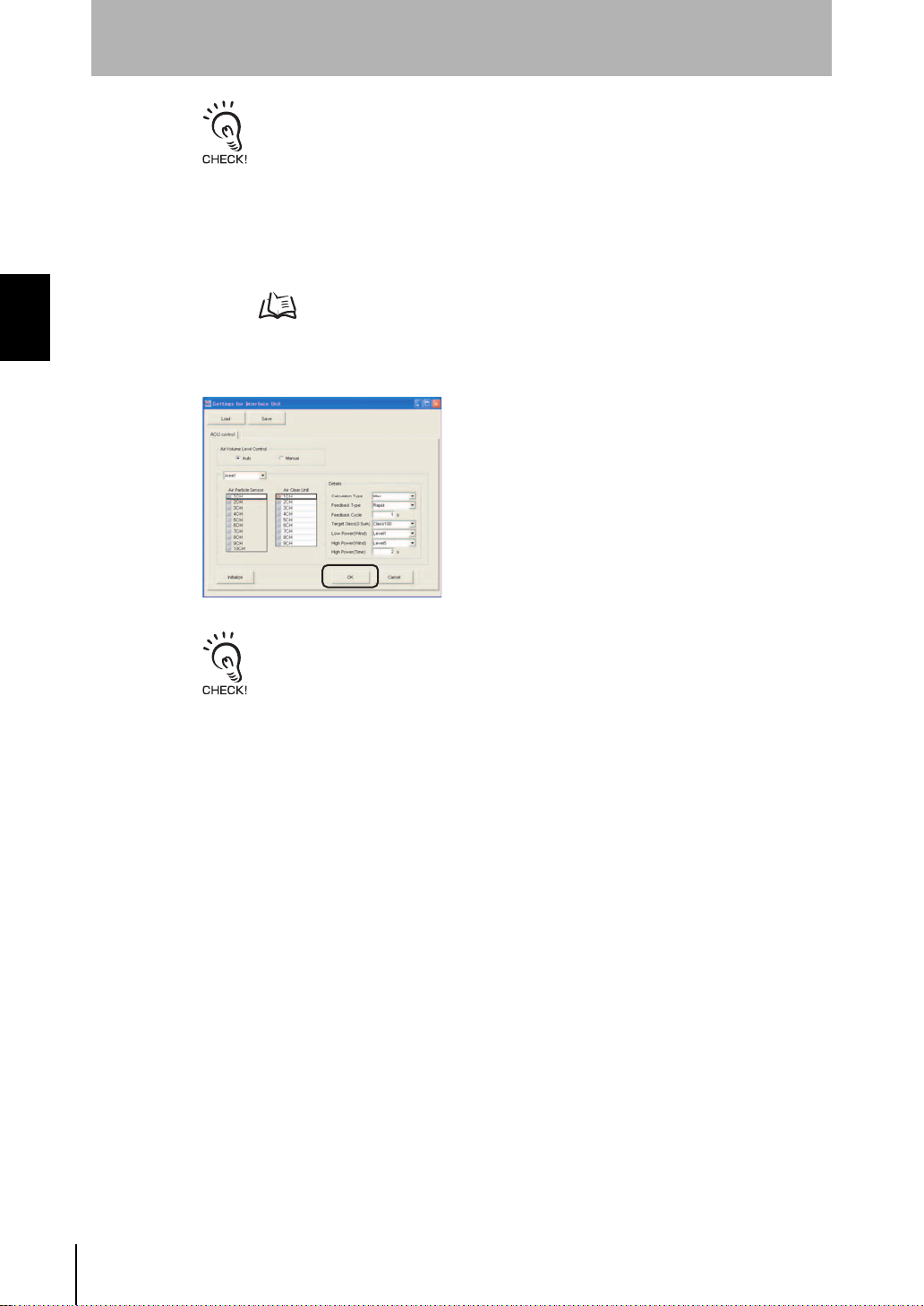
2. Click the [IFU Settings] button to display the Settings for Interface Unit screen.
3. In the Settings for Interface Unit screen, set the control conditions.
Set the information of the Air Clean Units and Air Particle Sensors located in the areas, and the
method for controlling the air volume level of the target areas.
Section 2 UPGRADING THE SYSTEM
The detailed settings are as follows:
Item Description
Calculation Type Selects the method for calculating the measured value.
Max: Select this parameter to set the maximum value of the
measurement result measured by the selected Air Particle
Sensor as the cleanliness of the target area.
Min: Select this parameter to set the minimum value of the
measurement result measured by the selected Air Particle
Sensor as the cleanliness of the target area.
Ave: Select this parameter to set the average value of the
measurement result measured by the selected Air Particle
Sensor as the cleanliness of the target area.
Feedback Type Selects the feedback method.
Feedback Cycle Selects the feedback cycle.
Target class(0.5µm) Selects the cleanliness class to be controlled.
Low Power(Wind) When "Constant" is selected at "Feedback Type", select the limit
value for the air volume beyond which air is not to be fed, and when
"Rapid" is selected, select the air volume level for when the
cleanliness has reached the target value.
High Power(Wind) Select the air volume level for when the cleanliness has not reached
High Power(Time) Select the time that the high power air volume level is to be held for.
the target value. This item can be selected only when "Rapid" is
selected at "Feedback Type".
System Manu al
ZN
33
Page 44
Section 2 UPGRADING THE SYSTEM
Section 2
Setup Methods Suited to Specific Applications
• For the high power air volume level, always set an air volume greater than the low power
air volume level. Feedback will not function properly if a smaller value is set.
• The time that the high power air volume level is actually held is an integer multiple of the
feedback cycle.
Example: When Feedback Cycle is set to "60 s" and High Power(Time) is set to "100 s",
the actual high power time is 120 s.
• We recommend setting the f eedback cycle to t he measurement cy cle of the Air Particle
Sensor or higher. Otherwise, feedback control will be endlessly executed based on the
same measurement result, and correct feedback control will not be possible.
How Feedback Control Works p.40
4. Click the [OK] button to start feedback controlled operation.
• When the setting is next used, feedback is automatically started simply by turning the Air
Clean Unit and Air Particle Sensor (and Interface Unit) power supplies ON.
• Feedback sometimes is not performed smoothly (i.e. a control lag occurs during
execution of feedback operation) when the power supply of the Air Clean Unit set as t he
control target in feedback control is not turned ON.
To solve this, either set feedback c ontrol so that it is performed only on po wered ON Air
Clean Units, or turn the power supply of all currently set Air Clean Units ON.
34
ZN
System Manu al
Page 45
Section 3
BASIC KNOWLEDGE OF CLEAN
SENSING SYSTEMS
Feedback Control 36
What is "Feedback?" 36
How Feedback Control Works 40
Clean Sensing 44
Principle o f "Particle Count" 44
What is "Cleanliness?" 45
Section 3 BASIC KNOWLEDGE OF CLEAN SENSING SYSTEMS
System Manu al
ZN
35
Page 46
Section 3
OPE1
OPE2
OPE3
Air Clean Unit
Air Particle Sensor
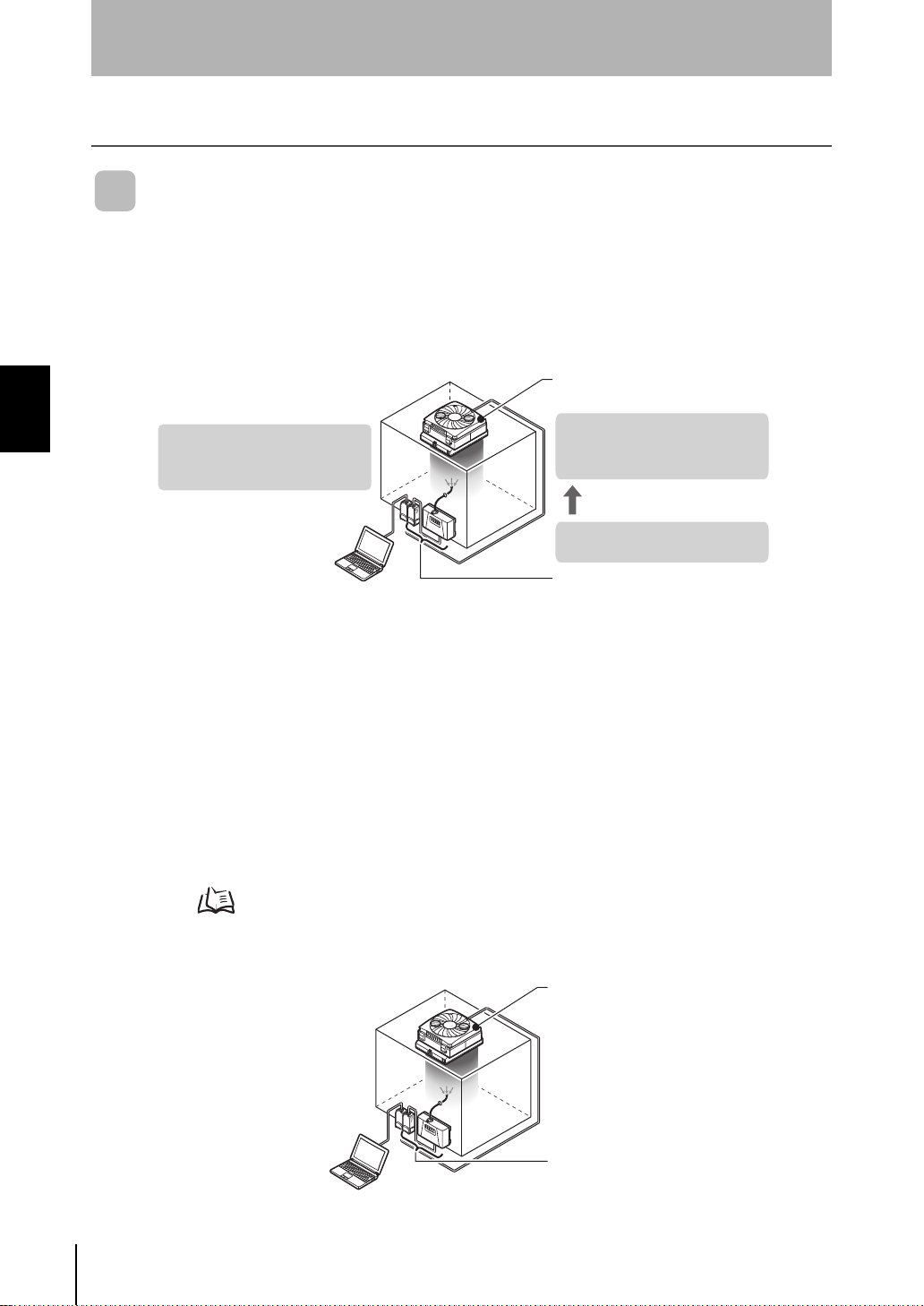
(3) Air volume level increases
to improve cleanliness
inside the area.
(1) Cleanliness inside the area
falls and is about to exceed
the target cleanliness.
(2) The command for increasing
the air volume level is sent.
OPE1
OPE2
OPE3
Air Clean Unit
Air Particle Sensor
Feedback Control
Feedback Control
What is "Feedback?"
"Feedback" is th e control o f the air vol ume level o f the Air Clea n Unit in pr oportion to
the amount of particles to maintain the cleanliness of target spaces. The ZN series
incorporates the "F O feedback" (Fle xible & Optimu m Feedback) funct ion. This control
program performs fl exible and optimum fe edback suited to the user's environment s o
Section 3 BASIC KNOWLEDGE OF CLEAN SENSING SYSTEMS
that a clean environment can be maintained and managed.
■ System Configuration
There are two system configurations that use the feedback function, a "direct clean
sensing system" and "multi-clean sensing system."
• Direct Clean Sensing System
In this system, the cleanliness of one area is managed by an Air Particle Sensor and an
Air Clean Unit.
Feedback processing is perfo rmed by the Air Parti cle Sen so r.
On the direct clean sensing system, you can select between "rapid feedback" and
"constant feedback" as the feedback method.
Feedback Methods p.38
Various feedback parameters (described later) can also be set.
ZN
System Manu al
36
Page 47

Section 3
Air Clean Unit
Air Particl e Sensor
Interface Unit
Feedback Control
• Multi-Clean Sensing System
In this system, the cleanliness of multiple areas is managed by multiple Air Particle
Sensors and multiple Air Clean Units.
The Interface Units acquire the da ta from the Air Particle Sensors th at are connected
together to perform feedback processing on the entire system.
Besides feedback processing on individual Air Particle Sensors, correspondence
between Air Particle Se nso r and A ir Cle an Un it c han nel s a nd c alc ul ati on o f Ai r Par tic l e
Sensor data also are possible.
Section 3 BASIC KNOWLEDGE OF CLEAN SENSING SYSTEMS
When using multiple Air Particle Sensors or multiple Air Clean Units, configure a multi-clean
sensing system using the ZN-SF12.
System Manu al
ZN
37
Page 48
Section 3
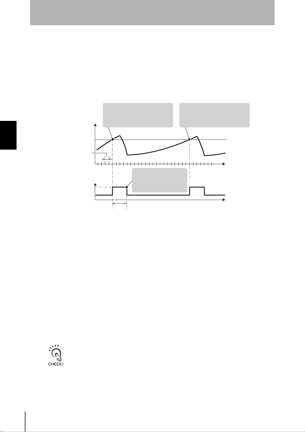
(2) When the high power
time elapses, the air
volume level returns
to low power.
(1) The air volume level is
changed to high power when
the cleanliness exceeds the
target cleanliness.
(3) The air volume level is
changed to high power when
the cleanliness exceeds the
target cleanliness again.
Amount of particles
Target cleanliness
High power air volume level
Low power air volume level
Feedback cycle
High power time
Time
Time
[Feedback Cycle]
• In a multi-clean sensing system:
The feedback cycle can be set on the Interface Unit.
• In a direct clean sensing system:
The feedback cycles equals the measurement time
of the Air Particle Sensor.
Feedback Control
■ Feedback Methods
There are two feedback methods, "rapid feedback" and "constant feedback."
• Rapid feedback
When cleanliness has deteriorated, rapid feedback quickly increases the air volume
level to recover the cleanliness.
This feedback method is effective in environments with relatively lots of change.
Section 3 BASIC KNOWLEDGE OF CLEAN SENSING SYSTEMS
<Feedback Operation>
• When the high power time is set to a value other than "0":
The high power air volum e level is switch ed to regardle ss of changes in the amount
of particles when the hig h p owe r air vo lum e level c ont inu es un til th e high power time
elapses.
• When the high power time is set to "0":
The high power air volume level continues until the amount of particles falls to a fixed
level or lower, and the low power air volume level is switched to.
ZN
System Manu al
38
• For the high power air volume level, set an air volume greater than the lower power air volume
level. Otherwise, feedback will not function properly.
• If the cleanliness is not restored after the high power time has elapsed, operation will continue at
the low power air volume level (i.e. the high power air volume level will not be switched to). When
this happens, either set a longer high power time or set the high power time to 0.
Page 49
Section 3
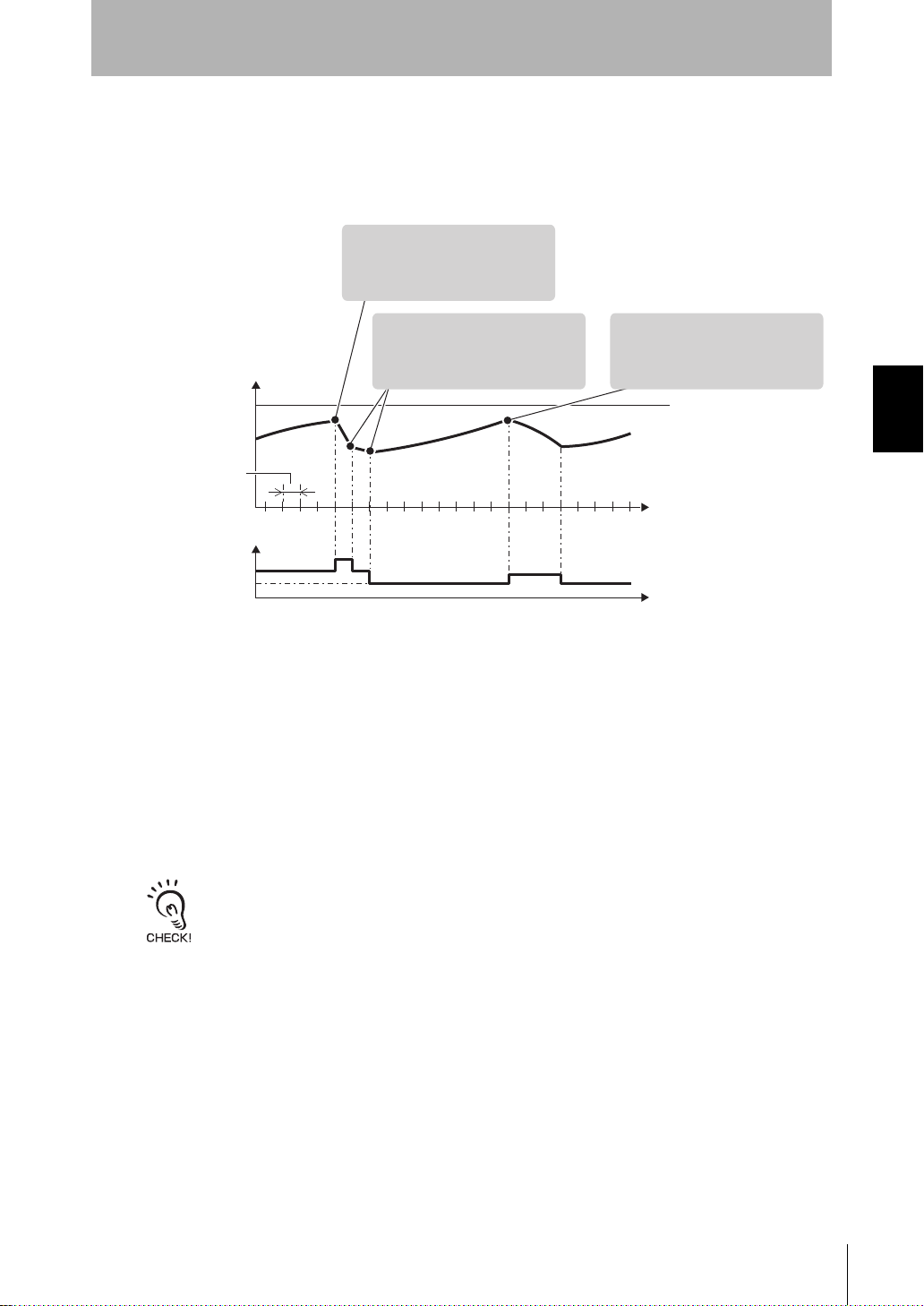
(1) The air volume level is
increased a level when the
target cleanliness is about
to be exceeded.
(2) The air volume level is
lowered a level when the
amount of particles is at a
fixed level or below.
Amount of particles
Target cleanliness
Low power air vo lu me leve l
Feedback cycle
Time
Time
[Feedback Cycle]
• In a multi-clean sensing system:
The feedback cycle can be set on the Interface Unit.
• In a direct clean sensing system:
The feedback cycle equals the "measurement time x 16"
of the Air Particle Sensor.
(3) The air volume level is
increased a level again
when the target cleanliness
is about to be exceeded.
Feedback Control
• Constant feedback
The air volume level is altered so that the cleanliness stabilizes at the target value.
This feedback method is effective in environments with relatively little change since the
cleanliness is maintained at the bare minimum air volume level.
Section 3 BASIC KNOWLEDGE OF CLEAN SENSING SYSTEMS
<Feedback Operation>
The air volume level is switched in stages according to the chang e in the amount of
particles.
The controlled air volume level never falls below the lower power air volume level.
Set the bare minimum air volume level as the lower power air volume level.
ZN
System Manu al
39
Page 50
Section 3
(1)
(
Air Clean Unit
Air Particle Sensor
Control signal
Area 1
Feedback Control
How Feedback Control Works
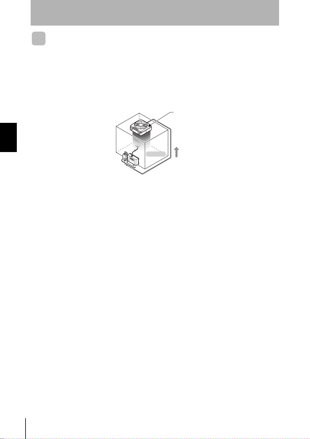
The following describ es the "flow of d ata for feedback" and "measurement p rocessing
flow" during feedback con tr ol for each sy s tem con fig ur ati on.
■ Direct Clean Sensing System
• Flow of data for feedback
Section 3 BASIC KNOWLEDGE OF CLEAN SENSING SYSTEMS
(3)
(2)
In a system configured as shown above:
(1) The a mou nt o f part ic les i n ar ea 1 i s detected by the Sensor, and the measuremen t
result is calculated by the Amplifier Unit.
(2) The control air volume level value of area 1 is calculated based on the
measurement results, pr eset target values and var ious feedback paramete rs, and
is sent to the Air Clean Unit.
(3) The air volume level is altered according to the controlled air volume level value
that arrives from the Air Particle Sensor.
40
ZN
System Manu al
Page 51
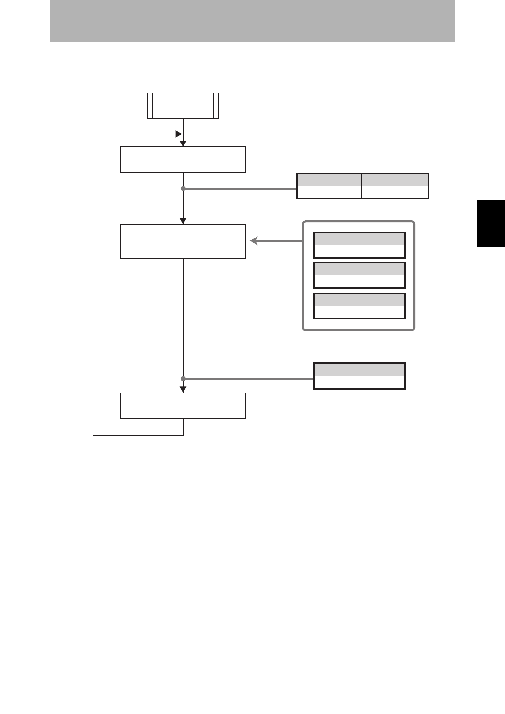
• Flow of processing on the Air Particle Sensor
Start of
measurement
Measurement result calculated
for each measurement time
Air Particle Sensor
1ch
Measurement result table (example)
Measured air volume level
calculated based on feedback
parameters
Setting values
to be used
Feedback Control
Measurement result
2000
Target level
1000
Feedback type
Constant
Low power air volume level
2
Section 3
Section 3 BASIC KNOWLEDGE OF CLEAN SENSING SYSTEMS
Control air volume level value
is sent by communications.
Calculation of control air
volume level value (example)
Control air volume level value
2
System Manu al
ZN
41
Page 52
Section 3
Air Clean Unit
Air Particle Sensor
Control signal
Area 1
Interface Unit
Area 2
Feedback Control
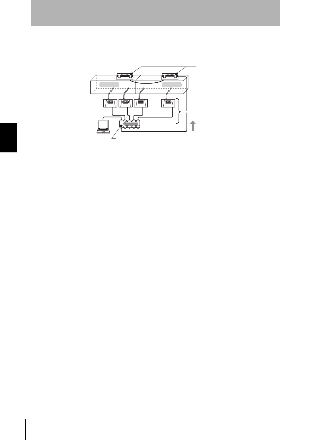
■ Multi-Clean Sensing System
• Flow of data for feedback
3CH
4CH
2CH
(3)
1CH2CH
1CH
Section 3 BASIC KNOWLEDGE OF CLEAN SENSING SYSTEMS
ZN-SF21
(1)
(2)
In a system configured as shown above:
(1) The a mount of par ticles in area 1 is detec ted by t he sens ors on ch annels 1 ch and
2ch, and the amount of particles in area 2 is detected by the sensors on ch annels
3ch and 4ch, the measureme nt result is calculated by the Am plifier Unit, and the
result is transferred to the Interface Unit.
(2) The controlled air volume level value of ea ch area is calculated based on preset
target values and various feedback parameters, the measurement results sent from
the Air Particle Sensor s on channels 1c h to 4ch, and is sen t to the Air Clean Units
on channels 1ch and 2ch.
(3) The air volume level is altered according to the controlled air volume level value
that arrives from the Interface Units.
42
ZN
System Manu al
Page 53

Section 3
Measurement result calculated
for each measurement time
Measured air volume level
calculated based on feedback
parameters
Measurement result
Air Particle Sensor
1 3500
Measurement result table (example)
Calculation method
Target level
Feedback type
MAX
1000
Constant
Control air volume level value
is sent by communications.
Start of
measurement
Area 1
Low power air volume level
3
2 2000
3 2500
4 3100
Calculation of control air volume
level value for each area
Enabled/
disabled
1ON
2ON
3 OFF
4 OFF
Air Particle
Sensor
Channel
Enabled/
disabled
1ON
2 OFF
Air Clean Unit
ID
Calculation method
Target level
Feedback type
AVE
1000
Constant
Area 2
Low power air volume level
2
Enabled/
disabled
1 OFF
2 OFF
3ON
4ON
Air Particle
Sensor
Channel
Enabled/
disabled
1 OFF
2ON
Air Clean Unit
ID
Calculation of control air volume level value
and measurement result for control (example)
1 3500
2 2800
Measurement result
for control
Area
Control air volume
level value
5
3
Setting values
to be used
Feedback Control
• Flow of processing on In terface Unit
The following shows an examp le of pr ocess ing flow du ring measure ment an d the da ta
to be used when feedback processing is performed under the following conditions:
• The Air Clean Unit (ID:1) is controlled based on the l arger value of the Air Particle
Sensors on channels 1ch and 2ch.
• The Air Clean Unit (ID:2) is controlled based on the average value of Air Particle
Sensors on channels 3ch and 4ch.
Section 3 BASIC KNOWLEDGE OF CLEAN SENSING SYSTEMS
System Manu al
ZN
43
Page 54

Section 3
Particles
Suction inlet
Receiving lens
Light-receiving lens
Fan
Amplifier Comparator
Light source
Emission lens
Signal processing circuit
Received light signal
Threshold
Time
Comparator
output
Incident
value
Received light signal and comparator output
Clean Sensing
Clean Sensing
Principle of "Particle Count"
The ZN-PD series judges the cleanliness of target spaces by measuring the amount of particles
(dust or dirt) floating in the air. The amount of particles is measured using the "fan method" and
"scattered light method" m ounted on the Air Particle Sensor (Senso r + Amplifier Unit).
Section 3 BASIC KNOWLEDGE OF CLEAN SENSING SYSTEMS
The ZN-PD series adopts the "fan method" for sucking in air. Compared with the "pump method"
used on handy-type particle sensors, for example, this method has a service life that is about 10
times longer. This enables the amount of particles to be measured stably over a long period of time.
(1)
(2)
(3)
(1) Air inside the clean booth is sucked in from the suction inlet by the fan.
(2) The sucked in air is illuminated by a laser beam.
If the air contains particles, the light is scattered.
(3) Particles a re detected by scattered lig ht entering the light receivi ng lens, and the
amount of particles is measured.
The scattered light ent ering the l ig ht rec ei ving lens is converted to electric si gnal by
the amplifier and comparator, and is sent to the signal processing circuit.
The amount of particles is measur ed ba se d on th e ele ctri ca l signals that are sent to
this circuit.
44
■ Measurement of the Amount of Particles
ZN
System Manu al
The amount of particles is measured bas ed on
the incident value. However, this incident value
increases the larger the particles become.
Thresholds are set for each of the target
particle diameters of 0.3 µm/0.5 µm/1.0 µm,
and the particle dia meter is judged according
to the size of the incident value.
Page 55
Section 3
1 max.
→ Class 1
100 max.
→ Class 100
10,000 max.
→ Class 10,000
1f
(approx.
30 cm)
1f
(approx.
30 cm)
1f
(approx.
30 cm)
Clean Sensing
What is "Cleanliness?"
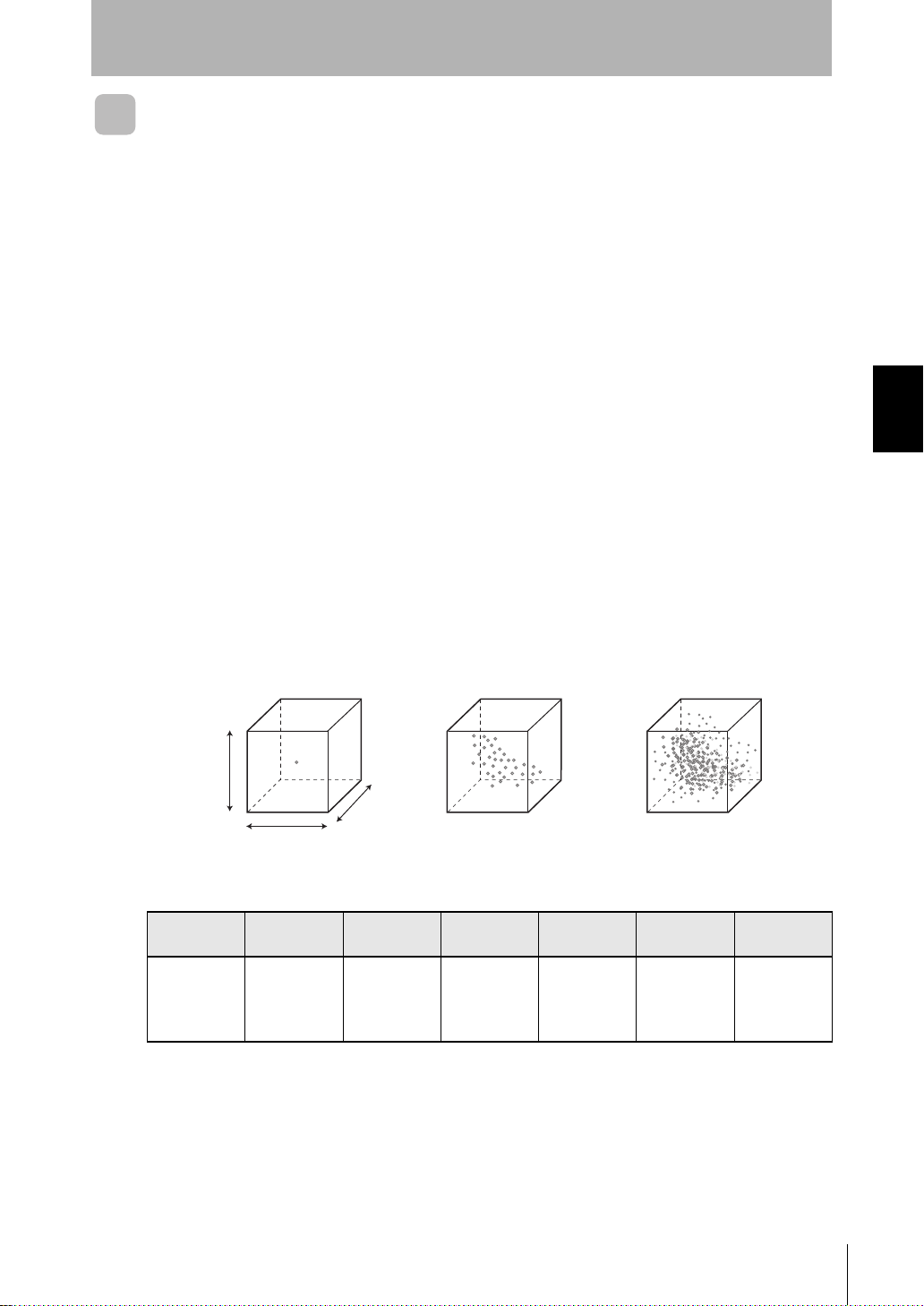
Cleanliness is expressed by the size, number and weight of polluting substances (dust,
dirt, etc.) contained in a fixed area or volume. The degree of cleanliness that is
indicated by the amount of dust or dirt contained in specific air is called the "cleanliness
level." This is further broken down into classes called "cleanliness class."
■ Cleanliness Standards
Standards that relate to the clea nliness of c lean room s, for exampl e, include Fed-Std209D in the United States and JIS B 9921 in Japan. The unit volume and particle
diameter of polluting su bstances that the criteria for these standards are based on are
different. The ZN series adopts cleanliness annotation that complies with Fed-Std209D, the most widely used standard at production sites.
■ Definition of Cleanliness According to Fed-Std-209D
Cleanliness is defined by the number of particles of 0.5 µm or more in diameter that are
contained in 1 cubic foot (28.3 liters or approximately a 30 cm cube) of air, and is
broken into classes de fine d by mul tip le s of ten. Thi s class i fic ati on is i ntu iti ve and e as yto-understand, and has been used the longest at production sites.
Section 3 BASIC KNOWLEDGE OF CLEAN SENSING SYSTEMS
Number of
particles of
0.5 µm or
more/cf
Class
1
1 10 100 1,000 10,000 100,000
Class
10
Class
100
Class
1,000
Class
10,000
Class
100,000
ZN
System Manu al
45
Page 56

Section 3
Clean Sensing
MEMO
Section 3 BASIC KNOWLEDGE OF CLEAN SENSING SYSTEMS
46
ZN
System Manu al
Page 57
Section 4
APPENDICES
Maintenance 48
Troubleshooting 50
Troubleshooting 50
Error Messages and Countermeasures 51
Specifications and Dimensions 53
List of Products 66
INDEX 69
Section 4 APPENDICES
System Manu al
ZN
47
Page 58
Section 4
Maintenance
Maintenance
For details on inspection and maintenance, refer to the Instruction Sheet for the respective product.
■ Air Clean Unit
ZN-A series filters are in a double-filter s tructure comprising a HEPA filter and a prefilter, and filter air that is sucked in.
• Periodic inspection
When the filter becomes dirty, highly clean air can no longer be suppl ied stably for a
long time. So, dust must be periodically removed from the pre-filter.
Section 4 APPENDICES
• Replacement
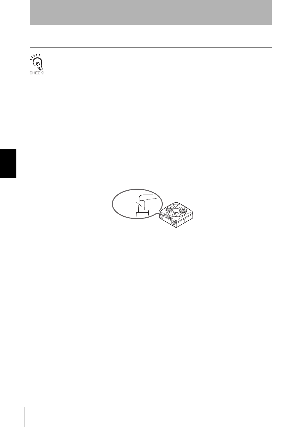
When the filter become s clogged, the two indicators (green/red) on the corner of the
body light simultaneously to notify that the filter must be replaced with a new one.
For details on how to repl ace the filter, refer to the Ins truction Sheet f or the Air Clean
Unit.
Indicator
■ Air Particle Sensor
The ZN-PDA series uses a high-performance fan on the suction module to enable
continuous operation.
• Periodic inspection
Dirt and dust car ried i n b y the fa n o n thi s sy st em caus es th e fil ter to become dirty over
extended use. When th e filter bec omes dir ty, the amount of particles can no longe r be
monitored accurately. So, dust must be periodically removed from the pre-filter.
If dirt on the pre-filter is stubbor n and cannot be removed, replace the pre-filter wit h
Filter Set ZN9-PF1 (sold separately).
• Cleaning
When the system has carried in air containing lots of particulates, install Cleaning Filter
ZN9-PC1 (sold separately) to maintain the inside of the Sensor in a clean state.
48
ZN
System Manu al
Page 59
Section 4
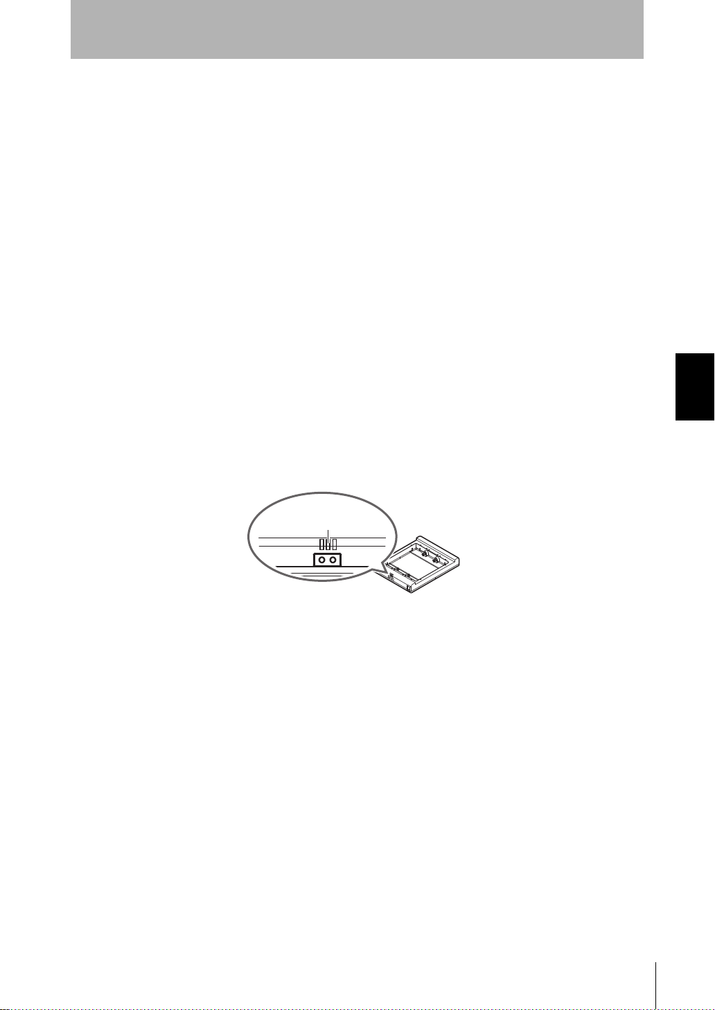
Cleaning notice/
warning indicator
Maintenance
■ Ionizer Unit
The ZN-J series generates ions by applying a high voltage on the discharge needles to
cause corona discharge.
• Periodic inspection
If the discharge needles become dirty or worn, the amount of generated ions
decreases and causes the neutralizing performance to drop. So, the discharge needles
must be cleaned periodically.
• Replacement
The cleaning noti ce indicator flashes orange to notify you that the discharg e needles
are dirty and the product's neutralizing capabilities are about to drop. The cleaning
notice indicator wil l stop flashing and stay lit (cleaning warn ing) when the discharge
needles become even dir tier and the product's neutral izing capabilities can no longer
be sustained.
Replace the discharge needle s if the cleaning warning indicator stays lit after they are
cleaned.
If the cleaning warning indicator lights even after replacing the discharge needles,
contact your OMRON representative.
For details on how to replace the di scharge needles, r efer to the Instructi on Sheet for
the Ionizer Unit.
Section 4 APPENDICES
System Manu al
ZN
49
Page 60

Section 4
Troubleshooting
Troubleshooting
Troubleshooting
This section describes countermeasures for temporary device problems. Check the
malfunction in this section before sending the hardware for repair.
For details on how to connect devices, refer to the Instruction Sheet for the respective product.
Problem Probable cause and possible countermeasure Pages
The sensor communications LED or
Section 4 APPENDICES
the external terminal
communications LED ERR indicator
does not light even after 5 seconds
has elapsed.
The Air Clean Unit power supply is
not ON.
The Air Particle Sensor power
supply is not ON.
No communications with personal
computer
(i)
The communications ports do
not match.
(ii)
The BUSY indicator does not
light up.
(iii)
There is no response from the
Interface Unit.
(iv)
An error message appears and
the Sensor cannot start up.
The respective product is not connected correctly.
• Is the mode switch on the Air Particle Sensor Amplifier Unit set to
RUN?
• Are the Amplifier Units connected correctly to each other, or is the
Interface Unit connected correctly to the Amplifier Unit?
• Has the Amplifier Unit started up properly?
• Check the power supply voltage if the DC power supply wire is
used.
• Is the AC adapter (provided) used?
• Check the power supply voltage if the DC power supply is used.
• Are all cables connected correctly?
Turn the power supplies of the Interface Unit and Air Particle Sensor
Amplifier Units OFF then back ON again.
If communications still does not start, check the following points (i) to
(iv), and then restart the Sensor.
• Set the same communications port No. as that on the personal
computer (the other communications conditions are set
automatically).
• Quit the application program that is using the communications
port.
No signal is being sent to the Interface Unit.
• Is the Sensor connected with the correct cable?
(Check if it is connected with a straight cable by mistake.)
• Is the sensor connected correctly?
• Is the correct communications port set?
• Is the switch on the rear of the Interface Unit set to the default
side?
• Is the mode switch on the Air Particle Sensor's Amplifier Unit set to
RUN?
Is the Interface Unit in use the correct one? (The dedicated Interface
Unit (ZN-SF11/SF12) is required to communicate with the ZN-PDA
series.)
-
-
-
-
-
-
p.17
-
50
ZN
System Manu al
Page 61

Section 4
Troubleshooting
Error Messages and Countermeasures
This section outlin es the error m essages that a re displa yed and the c ountermeasur es
for those messages. Check the malfunction in this section before sending the hardware
for repair.
■ Air Clean Unit (ZN-A Series)
[Indicator]
Indication Error Countermeasure
Green, red
lit simultaneously
Red lit The fan is rotating irregularly. Turn the fan power supply OFF then back ON again.
Green, blue
flashing
The air outlet or air inlet is
blocked.
The filter is blocked. Replace the filter.
The fan has reached the end of its
service life.
A voltage outside the rated
voltage is applied to the fan.
The I/O terminal power supply and
AC adapter are connected at the
same time .
The top case is open. Clos e the top case, turn the power supply OFF then
Remove the object blocking the air outlet or air inlet.
If turning the power supply OFF then back ON again
does not remedy the problem, contact your OMRON
representative.
Turn the fan power supply OFF then back ON again.
If turning the power supply OFF then back ON again
does not remedy the problem, a probable cause is that
the fan has reached the end of its service life. Contact
your OMRON representative.
Check the power supply voltage.
Check the power supply.
back ON again, and press the ON/OFF switch.
Section 4 APPENDICES
■ Ionizer Unit (ZN-J Series)
[Cleaning notice indicator/cleaning warning indicator]
Indication Error Countermeasure
Orange
flashing
Orange lit The discharge needles are dirty.
The discharge needles are dirty.
Continued use in this state will
cause neutralizing performance to
drop.
The neutralizing performance has
already dropped.
[Error output indicator]
Indication Error Countermeasure
Red lit Abnormal discharge Turn the power supply OFF then back ON again.
Clean the discharge needles.
Clean the discharge needles.
If this does not solve the error, the discharge needles
are worn. Replace the discharge needles.
If turning the power supply OFF then back ON again
does not remedy the problem, contact your OMRON
representative.
System Manu al
ZN
51
Page 62
Section 4
Troubleshooting
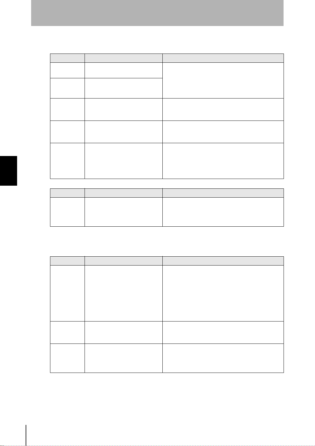
■ Air Particle Sensor (ZN-PDA Series)
[Main display]
Display Error Countermeasure
E-SEn
(flashing)
E-hEd
(flashing)
E-EEP
(flashing)
E-Sht
(flashing)
----- This error is indicated until the
Section 4 APPENDICES
[Sub-display (during communication status display)]
Display Error Countermeasure
Err-_ Communications timeout and
The Sensor fan or laser is in error
or has deteriorated.
The Sensor is not connected or is
in error.
The EEPROM is damaged or data
is in error.
One or all of the judgment outputs
is short-circuited.
initial data is obtained after the
power supply is turned ON or the
FUN mode is switched to the RUN
mode.
other communications errors
Check the connection with the Sensor and Amplifier
Unit, and turn the power supply OFF then back ON
again.
If this does not solve the problem, the Sensor is
malfunctioning. Replace the Sensor.
Hold down the ENT key for at least 3 seconds.
If this does not solve the error, the Amplifier Unit is
malfunctioning. Replace the Amplifier Unit.
Correct short-circuiting of short-circuited loads. (The
sensor is automatically restored after the shortcircuited load is canceled.)
The time it takes to obtain the initial data depends on
the settings for the number of samples to average and
the measurement time.
• Check the cable connection with the Air Clean Unit.
• Make sure that the channel No. of the Air Clean Unit is "0".
• Switch DIP switch 1 on the Air Clean Unit to ON
(external communications control enabled).
■ Interface Unit for Clean Monitoring System (ZN-SF Series)
[Main display]
Display Error Countermeasure
E-AmP
(flashing)
E-EEP
(flashing)
Err__
(during
communications
status di spl a y)
The Amplifier Unit is not
connected or the adjacent
Amplifier Unit cannot be
recognized correctly.
The EEPROM is damaged or data
is in error.
Communications timeout and
other communications errors on
the channel indicated by __.
• Set all mode switches on the Amplifier Unit to the
RUN mode.
• Make sure that the Amplifier Unit and Calculating
Unit are connected correctly, and turn the power
supply back ON again.
If this does not solve the problem, the Amplifier Unit
or Calculating Unit is malfunctioning. Replace the
Amplifier Unit or Calculating Unit.
Hold down the ENT key for at least 3 seconds.
If this does not solve the error, the Amplifier Unit is
malfunctioning. Replace the Amplifier Unit.
• Check the cable connection with the Air Clean Unit.
• Check the channel No. of the Air Clean Unit and the
feedback function settings.
52
ZN
System Manu al
Page 63
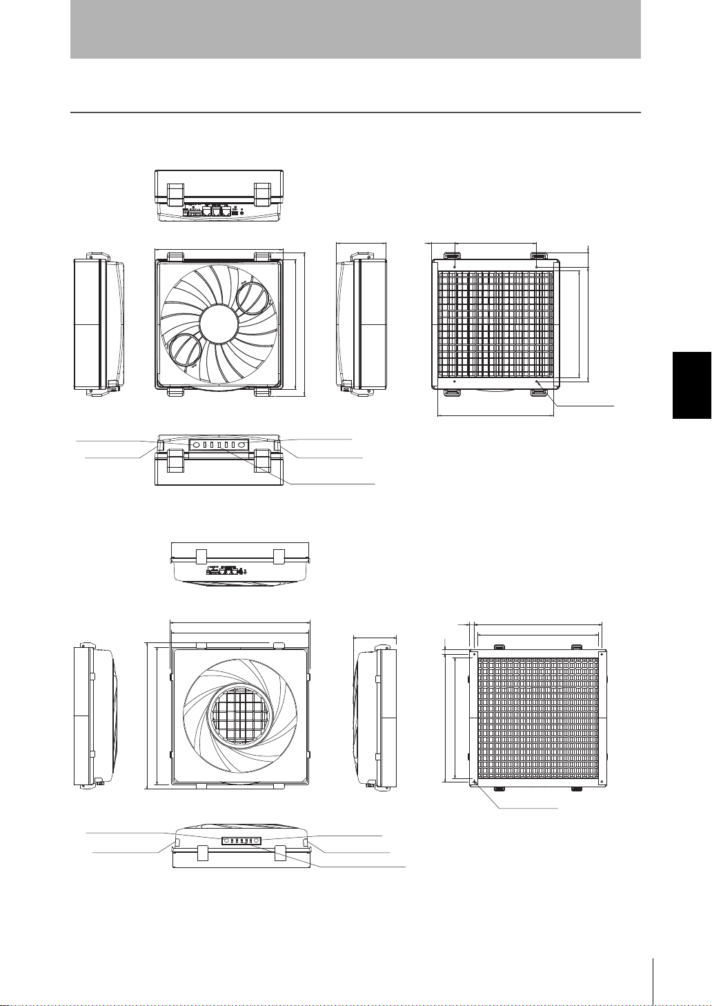
Specifications and Dimensions
276
250
250
97.5
45 160
28
220
226.6
205.6
4-M4, depth 17
Operation indicator
Operation indicator
Air volume level switch
Air volume level indicator
ON/OFF switch
(Unit: mm)
417
129.5
15
15 380
360
4-M5, depth 20
380
360
410
436
410
Operation indicatorOperation indicator
Air volume level switch
Air volume level indicator
ON/OFF switch
(Unit: mm)
Specifications and Dimensions
Air Clean Unit
ZN-A2502/A2502D
Section 4
Section 4 APPENDICES
ZN-A4105/A4105D
System Manu al
ZN
53
Page 64
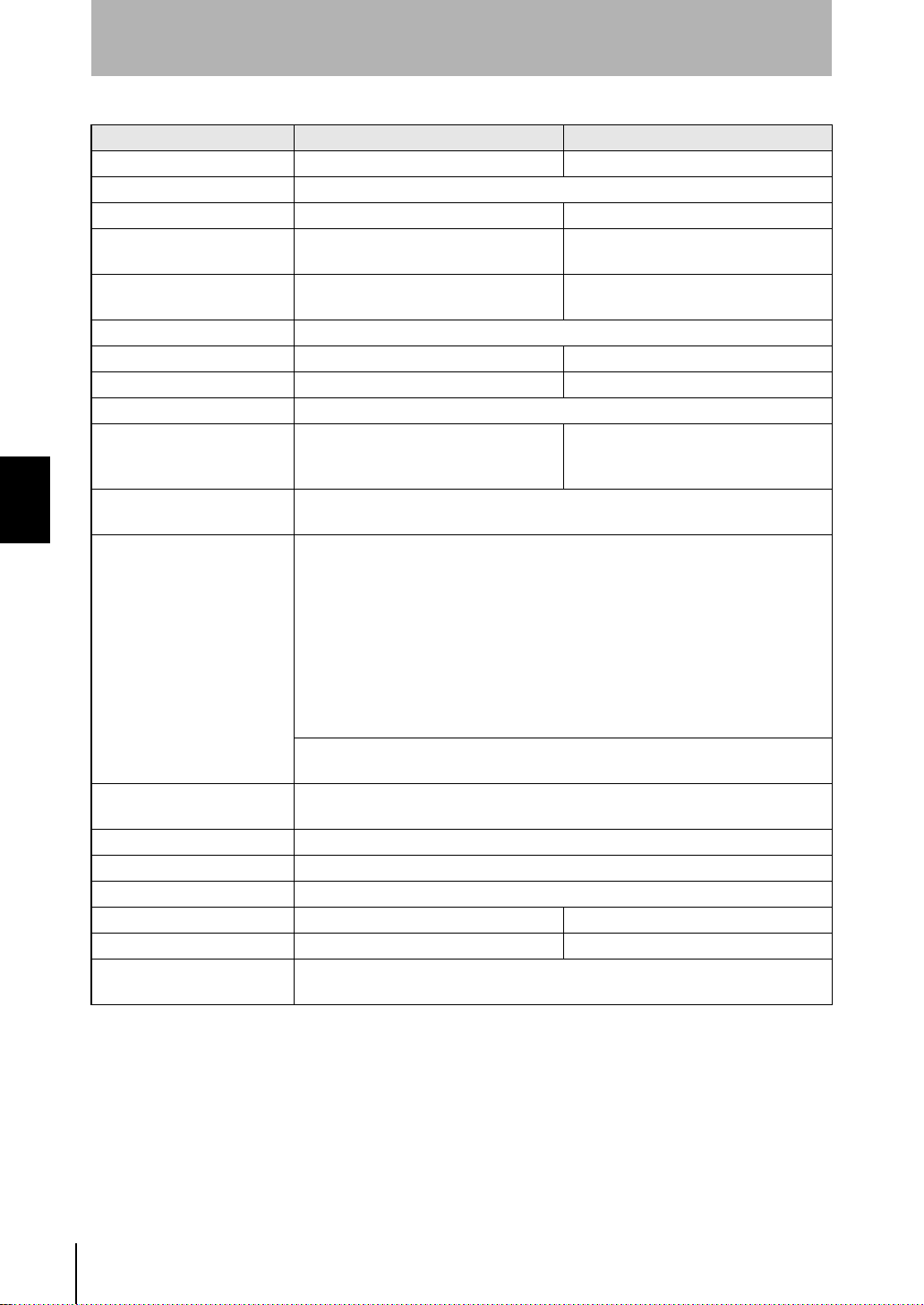
Section 4
Specifications and Dimensions
Item ZN-A2502/A2502D ZN-A4105/A4105D
Air outlet dimension 225 x 205 mm 360 x 360 mm
Particle outlet efficiency More than 99.99% for 0.3 µm particles
Air volume (m
Sound noise level (dB) Air volume level 3: 53 dB (typical)
Fan motor DC brushless compact centrifugal
Main filter HEPA filter
Main filter model ZN9-AHP25 ZN9-AHP41
Pre-filter model ZN9-APF25 ZN9-APF41
Power supply voltage 24 VDC ±10% Ripple (p-p) 10% max.
Current consumption
Section 4 APPENDICES
Indicator Operation: Green/Red
Output Alarm output 1: Alarm output 1 turns OFF when one of the following happens.
Functions Air volume selectable (Level 1 to 5), automatic control by ZN-PDA,
Ambient temperature Operating and storage: 0 to 40°C (with no icing or condensation)
Ambient humidity Operating and storage: 35 to 85% (with no condensation)
Material Upper case: ABS, Bottom frame: Steel
Dimensions (mm) 250 (W) x 250 (D) x 97.5 (H) 410 (W) x 410 (D) x 129.5 (H)
Weight (packed state) Approx. 2 kg (approx. 3.3 kg) Approx. 5.2 kg (approx. 8.6 kg)
Accessories Instruction Sheet, Sealing parts, Mounting screws, I/O connector (XW4B-06B1-H1),
(*1) AC adapter:
3
/min) 0.3 to 1.8 m3/min (typical) 1.0 to 5.0 m3/min (typical)
Air volume level 3: 53 dB (typical)
Air volume level 1: 41 dB (typical)
blower: 2
Air volume level 5:2.1 A max. (RMS value)
Air volume level 1:0.4 A max. (RMS value)
Air volume: Blue
(Normally, Alarm output 1 is ON.)
Check the indicator to find out which one is happening.
• Filter clogged
• Fan error
• Cleaning alarm for discharge needle (when ZN-J is used with)
• Discharge error (when ZN-J is used with)
Alarm output 2: Only for ZN-J used with
Alarm output 2 turns OFF with the cleaning notice for the discharge
needles. (Normally, Alarm output 2 is ON.)
30 VDC, 50 mA max.
Residual voltage: 1 V max. with load current 10 mA, 2 V max. with load current 50 mA
filter clogging alarm, available with ZN-J (Ionizer Unit), multi connection up to 9 units
AC adapter (*1) Not for ZN-A2502D, ZN-A4105D
made by Sanken Electric Co., Ltd. Model SEB100P2-24.0 (for ZN-A2502), Supply voltage 100 VAC to 240
VAC.
made by Sanken Electric Co., Ltd. Model SEC165P2-24.0 (for ZN-A4105), Supply voltage 100 VAC to 240
VAC.
Air volume level 1: 40 dB (typical)
DC brushless turbo fan: 1
Air volume level 5:3.5 A max. (RMS value),
(Peak: 5.5 A)
Air volume level 1:0.32 A max. (RMS value)
54
ZN
System Manu al
Page 65
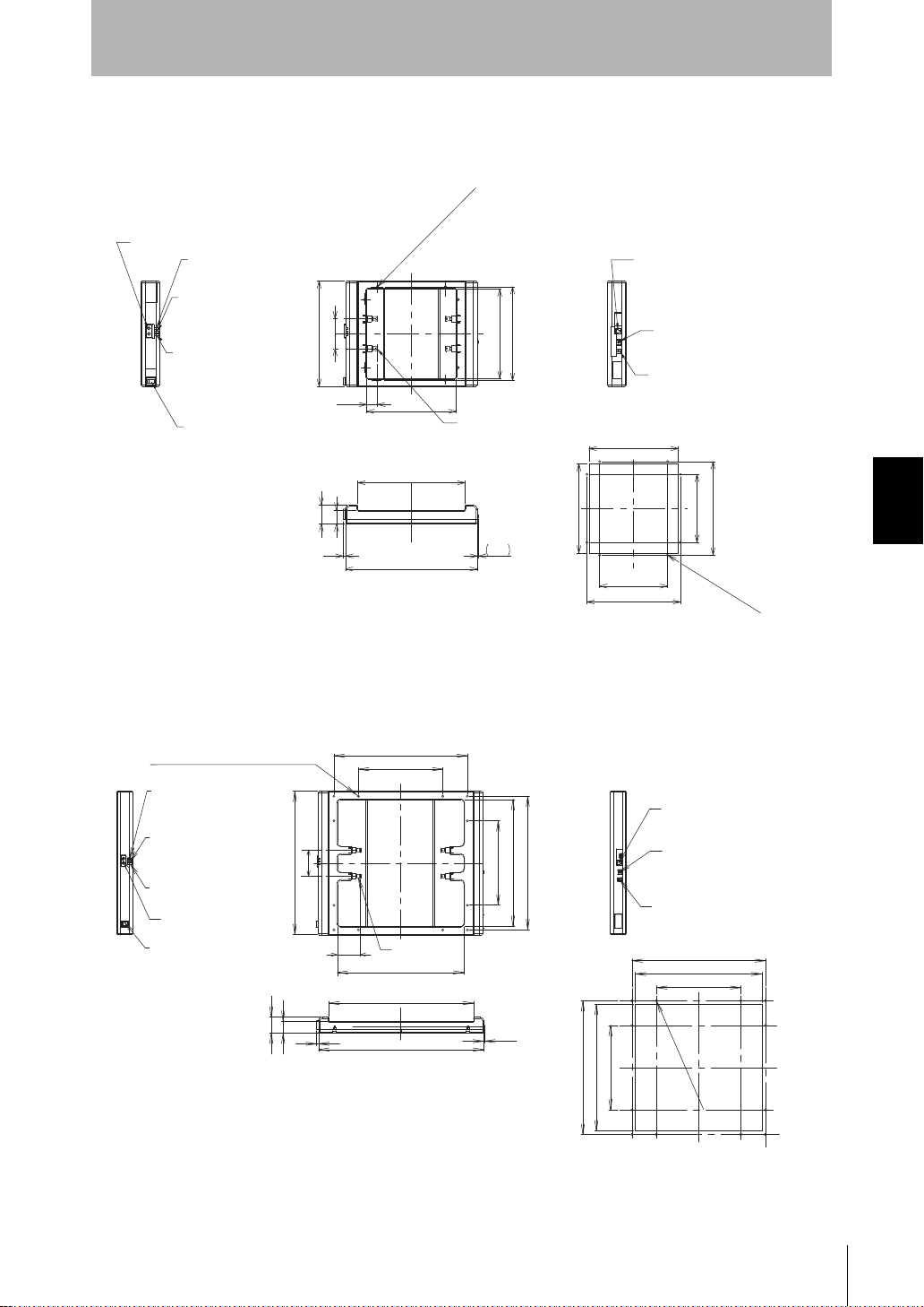
Ionizer Unit
Mount hole dimensions/panel cutout dimensions
252
6 3.3
33
45
310
AC adapter terminal
Power input
/signal output connector
GND terminal
/cleaning warning indicator
(orange lit)
Cleaning notice indicator
(orange flashing)
Ion balance adjustment buttons
Power switch
Error output indicator
(red flashing)
Power indicator
(green lit)
Discharge needles (4)
210
248
mm dia.
8- 5 Mount hole (thru hole)
210
25.50
220
70
210
160 ± 0.2
220 ± 0.2
220 ± 0.2
160 ± 0.2
210
8-5 mm dia. hole
(Unit: mm)
360
240 ± 0.2
380 ± 0.2
360
240 ± 0.2
380 ± 0.2
412
470
(3.3)
Power switch
Power indicator
(green lit)
Error output indicator
(red lit)
Ion balance
Adjustment buttons
Cleaning notice indicator
(orange flashing)
/cleaning warning indicator
(orange lit)
Power input/signal output connector
GND terminal
AC adapter terminal
45
33
6
Mount hole dimensions/panel cutout dimensions
12-6
mm dia. hol
e
Discharge
needles (4)
240
380
360
240
360
380
408
70
65.5
12-6 mm dia. mount hole (thru hole)
(Unit: mm)
ZN-J25/J25A
Section 4
Specifications and Dimensions
Section 4 APPENDICES
ZN-J41/J41A
System Manu al
ZN
55
Page 66
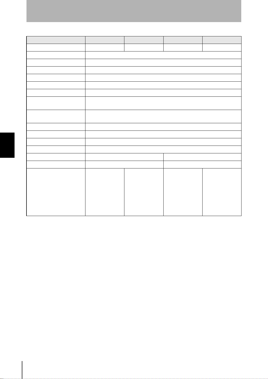
Section 4
Specifications and Dimensions
Item ZN-J25A ZN-J25 ZN-J41A ZN-J41
Available Air Clean Unit ZN-A2502 - ZN-A4105 Power supply voltage 24 VDC±10% Ripple (p-p) 10% max.
Current consumption 300 mA max
Output voltage ±7 kV max.
Discharge method Variable DC
Neutralizing time (typical) *1 5 sec max.
Ion balance (typical) *2 ± 30 V max.
Indicator Power (green), Cleaning notice (orange blinking), Cleaning warning (orange)
Error (red)
Output Error output,
cleaning notice/alarm output: photo MOS relay (30 VDC 300 mA max.)
Functions Manual ion balance adjustment, cleaning alarm, error alarm
Section 4 APPENDICES
Ambient temperature Operating and storage: 0 to 40°C (with no icing or condensation)
Ambient humidity Operating and storage: 35 to 65% (with no condensation)
Materials Case: ABS, Discharge needles: Tungsten
Dimensions (mm) 248 (W) x 310 (D) x 45 (H) mm 408 (W) x 470 (D) x 45 (H) mm
Weight (packed state) Approx. 0.6 kg (approx. 1.4 kg) Approx. 1.5 kg (approx. 2.7 kg)
Accessories Instruction sheet,
Sealing parts,
Mounting screws,
Connector cable
for Air Clean Unit,
Ferrite core,
English warning
label
(*1) Measurement conditions: Distance 300 mm, Air Clean Unit: ZN-A series
with air level 5, At center of air outlet,
Neutralization: From ±1000 V down to ±100 V with Charge Plate monitor (150 x 150 mm, 20 pF)
Temperature: 18 to 28°C, Humidity: 35 to 55%
The performance might not be able to be satisfied when there is gas such as solvent gas in the measurement
area.
(*2) Measurement conditions: Distance 300 mm, Air Clean Unit: ZN-A series
with air level 5, At center of air outlet,
Measurement time: 10 seconds at Charge Plate monitor (150 x 150 mm, 20 pF)
Temperature: 18 to 28°C, Humidity: 35 to 55%
The performance might not be able to be satisfied when there is gas such as solvent gas in the measurement
area.
(*3) AC adapter: made by Sanken Electric Co., Ltd. Model SEA40N2-24.0, Supply voltage 100 VAC to 240 VAC.
Instruction sheet,
Sealing parts,
Mounting screws, I/
O cable (2 m), AC
adapter (*3),
Ferrite core,
English warning
label
Instruction sheet,
Sealing parts,
Mounting screws,
Connector cable
for Air Clean Unit,
Ferrite core,
English warning
label
Instruction sheet,
Sealing parts,
Mounting screws, I/
O cable (2 m), AC
adapter (*3),
Ferrite core,
English warning
label
56
ZN
System Manu al
Page 67
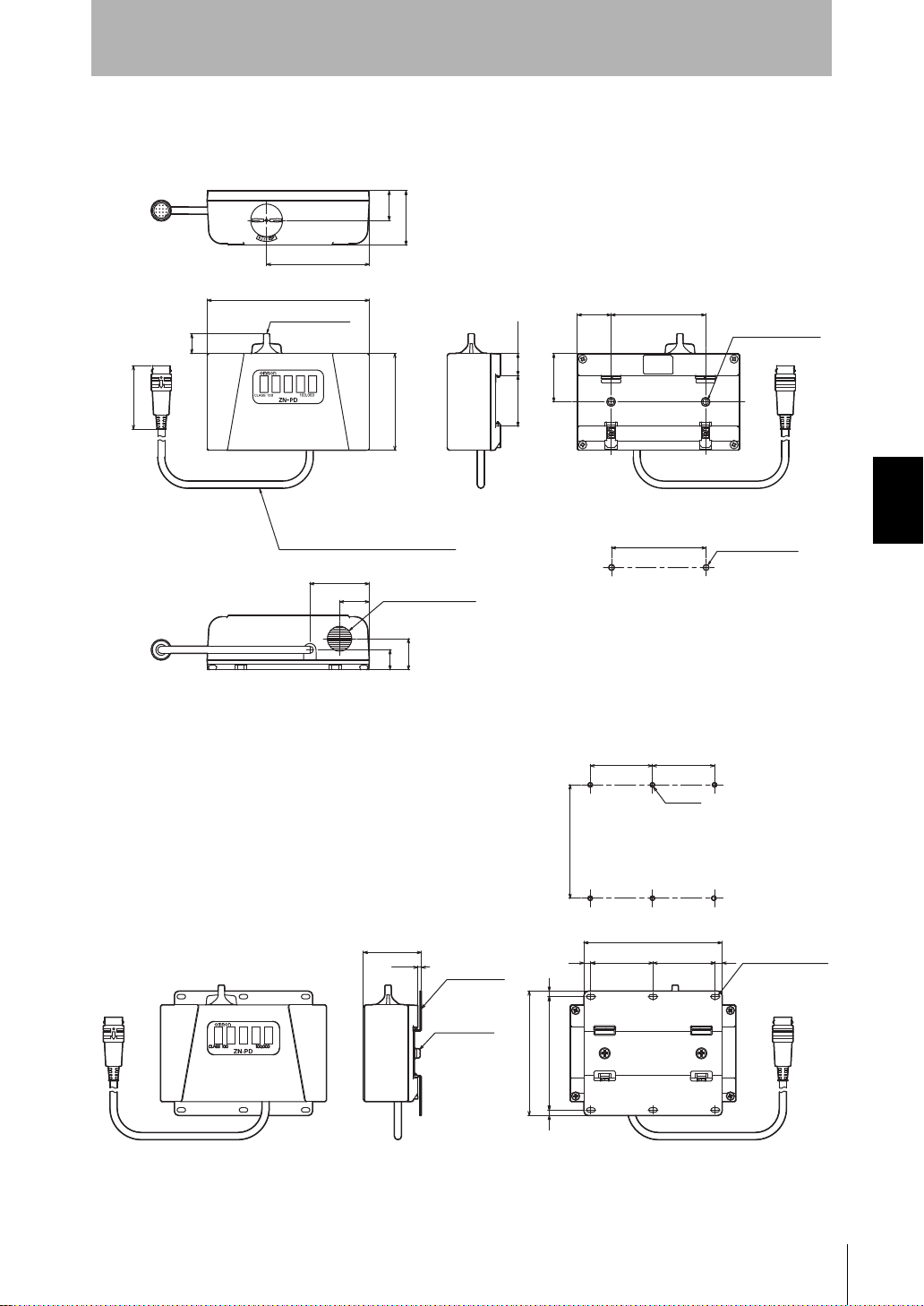
Air Particle Sensor
1
a.
(Unit: mm)
Round vinyl insulated cable
5.2 mm dia., 10-wire
Standard length: 0.5 m
Suction inlet
Exhaust outlet
Mount hole dimensions
Mounting
screw holes
2-M4, depth 6
(Unit: mm)
Mount hole d ime n s i on s
Mounting
bracket
Oblong mount
hole
6-3.2 x 6.2
Mounting
screws
2-M4x6
• Sensor
ZN-PD03
76
Section 4
Specifications and Dimensions
21.5
39.4
120
14.3
46
44
22
70
14.4
22.4
15.85
36.8
25 70
35
When sensor mounting bracket (ZN9-PB1, sold separately) is used
70
0.
4545
6-M3
2
4.2 mm di
Section 4 APPENDICES
82 ± 0.1
42
2.6
82 44
(90)
(100)
455545
ZN
System Manu al
57
Page 68

Section 4
Specifications and Dimensions
Item ZN-PD03
Available Amplifier Unit ZN-PDA 11/ZN-PDA12
Measurement method 90° sideway light-scattering method
Light source Semiconductor laser
Available particle size 0.3 µm/0.5 µm/1.0 µm
Available cleanliness class Class100 to 100,000 corresponding (FED-STD-209D)
Indicator Level indicator for Class100 to 100,000 (FED-STD-209D)
Suction tube Inside diameter: 4 mm, Length: 1 m max.
Ambient temperature Operating: 0 to 40°C, Storage: -15 to +50°C (with no icing or condensation)
Ambient humidity Operating and storage: 35 to 85% (with no condensation)
Dielectric strength 1,000 VAC, 50/60 Hz for 1 min
Vibration resistance 10 to 55 Hz, 0.7-mm double amplitude 80 min each in X, Y and Z directions
Section 4 APPENDICES
Shock resistance 150 m/s
Connection method Connector cable (standard cable length: 0.5 m)
Materials ABS
Weight (packed state) Approx. 300 g (approx. 450 g)
Accessories Instruction sheet, Suction tube
2
3 times each in six directions (up/down, left/right, forward/backward)
58
ZN
System Manu al
Page 69
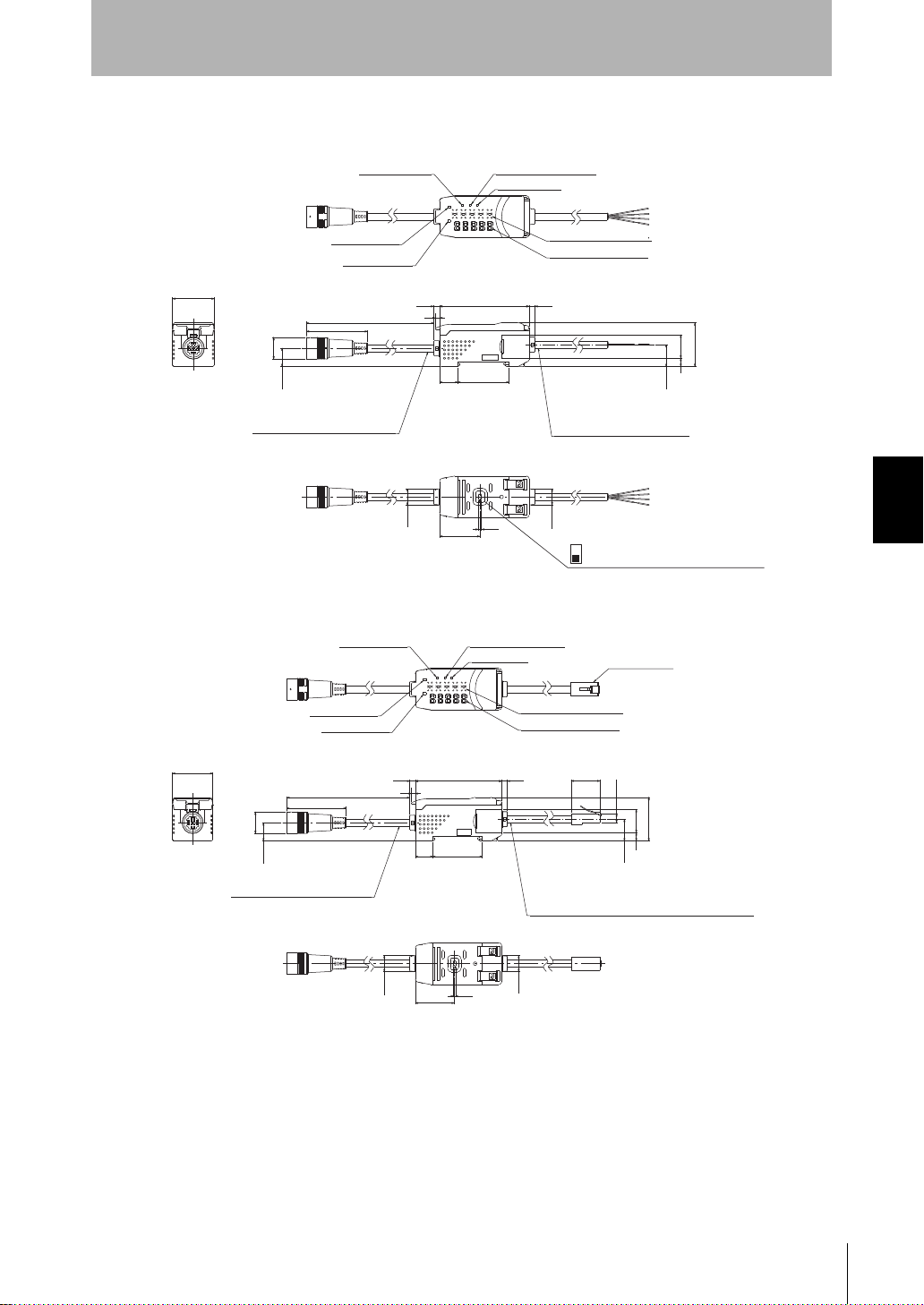
• Amplifier Unit
(Unit: mm)
(Unit: mm)
ZN-PDA11
Section 4
Specifications and Dimensions
Wide range indicatorPower indicator
Unit indicator
ZN-PDA12
OUT1 indicator
OUT2 indicator
30
(133)
44
15.5 mm dia.
13.2
Round vinyl insulated cable
5.1 mm dia. standard 100 mm
3
36.813
Main display indicator
Sub-display indicator
4.264.34.2
Round vinyl insulated cable
5.2 mm dia. standard 2 m
15.8
31.5
16.86
Section 4 APPENDICES
Power indicator
OUT1 indicator
OUT2 indicator
11.7
2.2
29
Wide range indicator
Unit indicator
Judgment output OUT2/reset input switch
11.7
(Default setting is judgment output.)
Judgment outputs
Modular jack
Main display indicator
Sub-display indicator
30
15.5 mm dia.
13.2
Round vinyl insulated cable
5.1 mm dia. standard 100 mm
21.46
6.6
31.5
16.86
Round vinyl insulated cable 5.1 mm dia., 10-wire
(conductor cross-sectional area: 0.08 mm
insulator diameter: 0.7 mm)
standard 2 m
15.8
2
/
11.7
3
36.813
29
(133)
44
2.2
4.264.34.2
11.7
ZN
System Manu al
59
Page 70
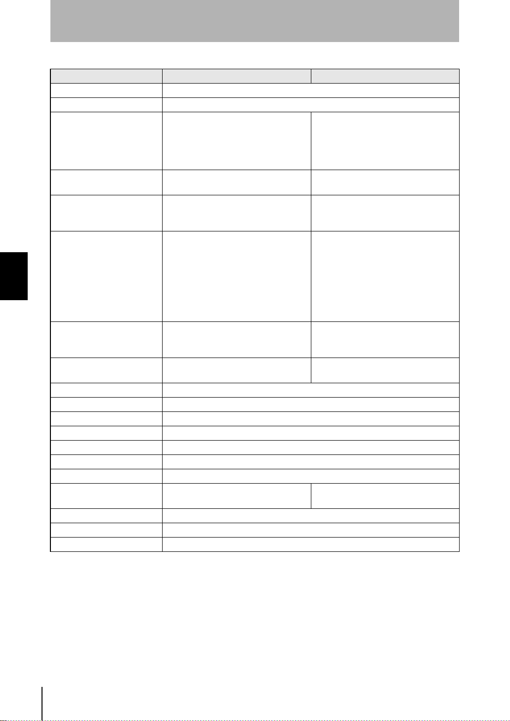
Section 4
Specifications and Dimensions
Item ZN-PDA11 ZN-PDA12
Sampling time 1 to 599 s (selectable)
Average count setting 1/2/4/8/16/32/64
Indicator Operation indicators: OUT1 (orange),
OUT2 (yellow), 7-segment main display
(red), 7-segment sub-display (yellow)
Power (green), wide range display
(green), unit selection display (green)
Judgment outputs OUT1/
OUT2(*1)
Reset input *1 ON: Short-circuited with 0 V terminal or
Functions Measured value display, setting value
Section 4 APPENDICES
Communication
with Air Clean Unit
Power supply voltage 24 VDC±10% Ripple (p-p) 10% max. 24 VDC±10% Ripple (p-p) 10% max.
Current consumption 300 mA max.
Ambient temperature Operating: 0 to 40°C, Storage: -15 to +50°C (with no icing or condensation)
Ambient humidity Operating and storage: 35 to 85% (with no condensation)
Insulation resistance 20 MΩ at 500 VDC
Dielectric strength 1,000 VAC, 50/60 Hz for 1 min
Vibration resistance 10 to 150 Hz, 0.7-mm double amplitude 80 min each in X, Y and Z directions
Shock resistance 300 m/s
Connection method Cable
Materials Case: PBT (polybutylene terephthalate), Cover: polycarbonate
Weight (packed state) Approx. 180 g (approx. 350 g)
Accessories Instruction sheet
((*1) Judgment output OUT2 and reset input are switched by the DIP switch on the rear of the Amplifier Unit.
NPN open-collector outputs, 30 VDC
30mA max., Residual voltage: 1.2 V max.
1.5 V or less
OFF:Open
display, unit selection,
scaling, peak hold,
hysteresis setting, threshold level
selection,
wide range display, key lock,
ECO mode, display reverse,
display digit change, initial reset
- Unique communication specification
2
3 times each in six directions (up/down, left/right, forward/backward)
(standard cable length: 2 m)
7-segment main display (red), 7-segment
sub-display (yellow),
Power (green), wide range display
(green), unit selection display (green)
-
-
Measured value display, communication
status display, unit selection,
scaling, Air Clean Unit automatic control,
Air Clean Unit air level change, wide
range display, key lock,
ECO mode, display reverse,
display digit change, initial reset
(RJ-45 connector and straight wiring LAN
cable)
(supplied by Air Clean Unit)
Connector cable
(standard cable length: 2 m)
60
ZN
System Manu al
Page 71
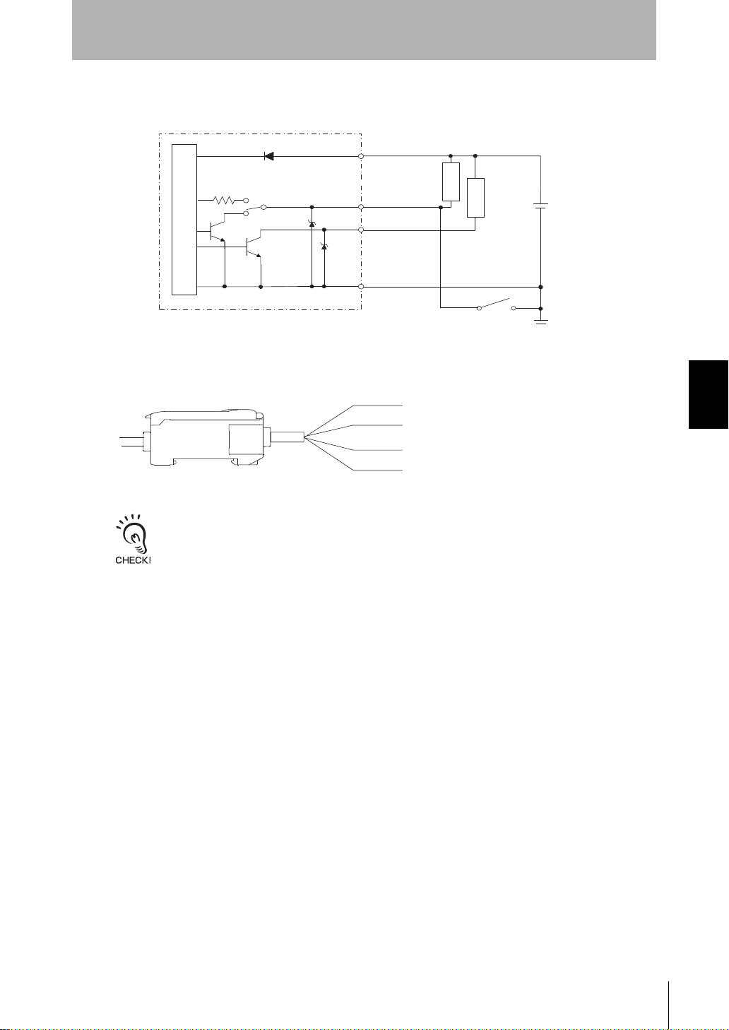
■ I/O Circuit Diagram
C
{
n
ue
y
W
e
(1) 24 VDC
(2) GND (0V)
(3) Warning judgment output
(4) Caution judgment output
(5) Reset input
NPN type (ZN-PDA11)
Brown
Section 4
Specifications and Dimensions
24 VDC
I/O switch
Caution judgment
output
White
Reset input
Warning judgment
output
Gray
Load
Load
24 VD
Internal circuit
GND (0V)
Blue
■ External I/O
Brow
Bl
Gra
hit
• Wire the cable correctly. Otherwise, the Amplifier Unit might be damaged.
• The function of the white lead can be selected by the switch on the rear of the Amplifier Unit.
(1)This is the power terminal. Connect the 24 VDC power supply to this terminal.
(2)This is the 0 V power s upply term inal. On an NP N type Am plifier Uni t, this termi nal
becomes the common terminal for inputs/outputs other than the linear output.
(3)This output turns ON when "measured value ≥ warning threshold".
Operation is the same as lighting of the OUT1 indicator.
(4)This output turns ON when "measured value ≥ caution threshold".
Operation is the same as lighting of the OUT2 indicator.
(5) This input is for resetting each of the outputs. When this input is ON, internal
calculations are stopped, and judgment outputs are fo rcibly tur ned OFF. This input
can also be used to clear the peak hold value.
Section 4 APPENDICES
System Manu al
ZN
61
Page 72
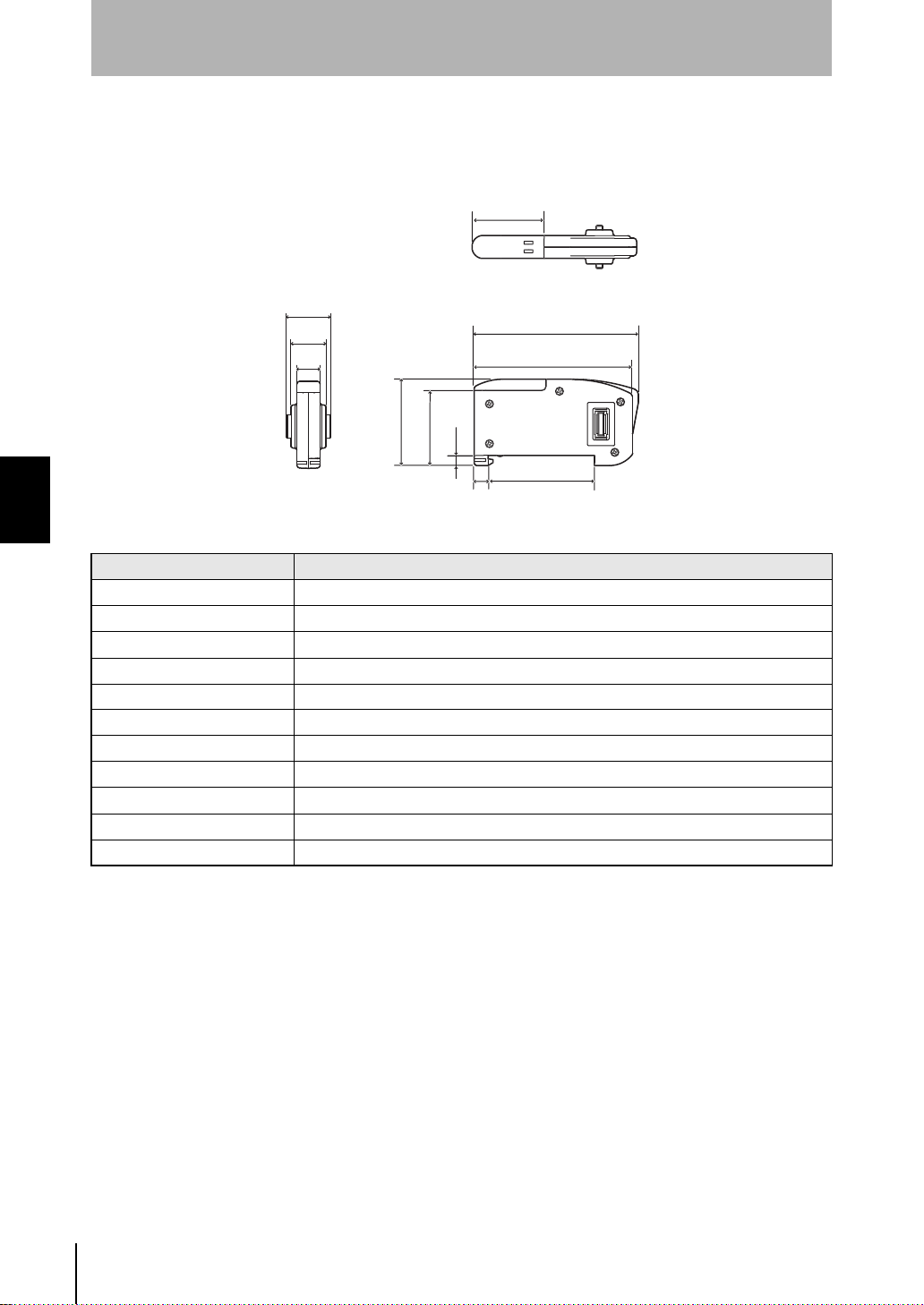
Section 4
6
57
54.9
5
36.7
9
(Unit: mm)
Specifications and Dimensions
• Calculating Unit
ZX-CAL2
24.
15.1
12
8
2
.4
Section 4 APPENDICES
Item ZX-CAL2
Available Amplifier Unit ZN-PD series, ZX series, ZJ-SD series
Current consumption 12 mA or less (supplied from the Amplifier Unit)
Ambient temperature Operating: 0 to 50°C, Storage: -15 to +60°C (with no icing or condensation)
Ambient humidity Operating and storage: 35 to 85% (with no condensation)
Connection method Connector
Dielectric strength 1,000 VAC, 50/60 Hz for 1 min
Insulation resistance 100 MΩ at 500 VDC
Vibration resistance 10 to 150 Hz, 0.7-mm double amplitude 80 min each in X, Y and Z directions
Shock resistance 300 m/s
Materials Display: Acrylic, Case: ABS resin
Weight (packed state) Approx. 50 g
2
3 times each in six directions (up/down, left/right, forward/backward)
ZN
System Manu al
62
Page 73
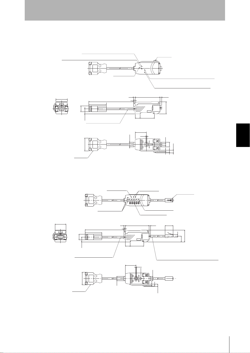
Interface Unit for Clean Monitoring System
(Unit: mm)
(Unit: mm)
ZN-SF11
Section 4
Specifications and Dimensions
ZN-SF12
Sensor communications indicator (busy)
Sensor communications indicator (communications error)
Power indicator
30
15
Round vinyl insulated cable
13.2
5.2 mm dia. standard 300 mm
(33.1)
Connector
(46)
(336)
Power indicator
4.2
3
11. 7
Connector
External terminal communications indicator (busy)
External terminal communications indicator
(communications error)
64.3
36.813
29
2.2
Status indicator
4.2
31.5
4.3
3
11. 7
5
6.55
Modular jack
Section 4 APPENDICES
Operation indicator
30
(336)
(46)
15
13.2
Round vinyl insulated cable
5.2 mm dia. standard 300 mm
(33.1)
Connector
3
29
11.7
Main display indicator
Sub-display indicator
36.813
2.2
4.3
4.264.34.2
21.46
6.6
31.5
15.8
Round vinyl insulated cable 5.1 mm dia., 10-wire
(conductor cross-sectional area: 0.08 mm
insulator diameter: 0.7 mm)
standard 2 m
11.7
3
5
6.55
2
/
ZN
System Manu al
63
Page 74
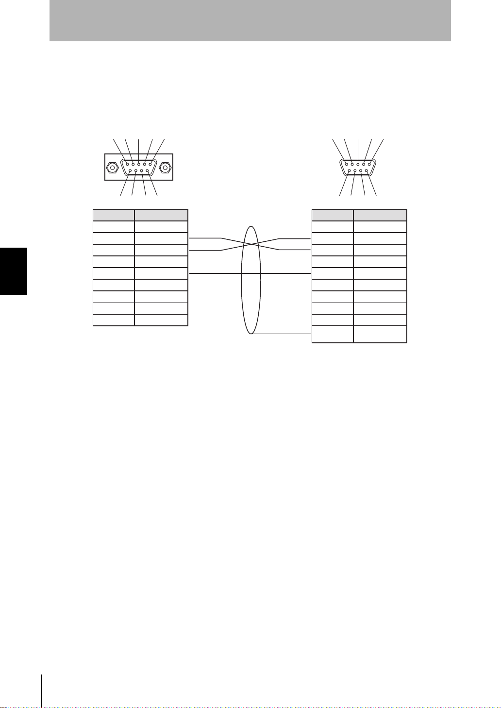
Section 4
Connect the ZN-SF11/SF12
and the personal computer
using a 9-pin D-sub cross
cable (female-female).
Personal computer side (PC/AT compatible)ZN-SF11/SF12 side
* Pin Nos. may vary with the type and
model of the external device to be
connected. For details, refer to the
instruction manual of your programmable
controller or personal computer.
Specifications and Dimensions
■ Connector Pin Arrangement and Connection Example with
Personal Computer
12 3 45
67 89
Pin No.Name
1 N.C.
Section 4 APPENDICES
2RD
3SD
4 N.C.
5SG
6 N.C.
7 N.C.
8 N.C.
9 N.C.
12 3 45
67 89
Pin No.Name
1CD
2RD
3SD
4ER
5SG
6DR
7RS
8CS
9CI
Connector
hood
FG
64
ZN
System Manu al
Page 75
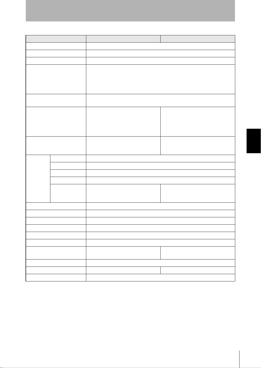
Section 4
Specifications and Dimensions
Clean Monitoring System
Item ZN-SFW11 ZN-SFW12
Power supply voltage Supplied from ZN-PDA
Current consumption 45 mA with 24 VDC without Amplifier Unit
Available Sensor Amplifier ZX series, ZJ-SD series, ZN-PD series
Available Sensor Amplifier
software version
Available number of connected
Sensor Amplifiers
Indicator Power : green
Functions - Air Clean Unit automatic control
Communication
Ambient temperature Operating: 0 to 40°C, Storage: -15 to +50°C (with no icing or condensation)
Ambient humidity Operating and storage: 35 to 85% (with no condensation)
Insulation resistance 20 MΩ at 500 VDC
Dielectric strength 1,000 VAC, 50/60 Hz for 1 min
Vibration resistance 10 to 150 Hz, 0.7-mm double amplitude 80 min each in X, Y and Z directions
Shock resistance 300 m/s
Connection method - Connector cable
Materials Case: PBT (polybutylene terephthalate), Cover: polycarbonate
Weight (packed state) Approx. 100 g (approx. 480 g) Approx. 200 g (approx. 550 g)
Accessories CD-ROM (Realtime Clean Air Monitor), Instruction sheet, two clamps
Port RS-232C (9-pin D-sub connector)
Protocol CompoWay/F
Baud rate 38400 bps
Data configuration Data bits: 8, Parity: none, Start bits: 1, Stop bits: 1, Flow control: none
For external
device 2
ZX-LDA__-N V1,000 or higher
ZX-EDA__ V1,300 or higher
ZX-TDA__ V1,100 or higher
ZX-SDA__ V1,000 or higher
ZX-PDA__ V1,000 or higher
10 max. (for ZN-PDA)
Power (POWER: green)
Sensor communications busy: green
Sensor communications error: red
Serial communications: green
Serial communications error: red
- Unique communication specification
2
3 times each in six directions (up/down, left/right, forward/backward)
Serial communications (STA1: green)
Not Clean (OPE1: orange)
Clean (OPE2: green)
(multiple unit system control)
Air Clean Unit air level change
(RJ-45 connector and straight wiring
LAN cable)
(standard cable length: 2 m)
Section 4 APPENDICES
System Manu al
ZN
65
Page 76
Section 4
List of Products
List of Products
■ Air Clean Unit
• Main unit
Type Model Remarks
250 mm Square ZN-A2502
250 mm Square ZN-A2502D Without AC adaptor
410 mm Square ZN-A4105
410 mm Square ZN-A4105D Without AC adaptor
When connecting multiple Air Clean Units to build a system, use a commercially available LAN
cable (straight type: Category 5E or higher).
Section 4 APPENDICES
• Accessories
Type Model Remarks
Replacement filter ZN9-AHP25 1 (for 250 mm Square filter)
ZN9-AHP41 1 (for 410 mm Square filter)
Replacement pre-filter ZN9-APF25 2 (for 250 mm Square filter)
ZN9-APF41 1 (for 410 mm Square filter)
■ Ionizer Unit
• Main Unit
Type Model Remarks
250 mm Square ZN-J25A When used together with the Air Clean Unit (ZN-A2502) as
a set
410 mm Square ZN-J41A When used together with the Air Clean Unit (ZN-A4105) as
a set
250 mm Square ZN-J25
410 mm Square ZN-J41
• Accessories
Type Model Remarks
Replacement needles ZN9-JH04 4 (with needle holder)
Single-ended connector
cable 5 m
Single-ended connector
cable 10 m
ZN-JC05 1 (for DC power supply, I/O cable connection)
ZN-JC10 1 (for DC power supply, I/O cable connection)
66
ZN
System Manu al
Page 77
■ Air Particle Sensor
• Main Unit
Type Model Remarks
Sensor ZN-PD03
Amplifier Units ZN-PDA11 Cable type 2 m
ZN-PDA12 Connector type 2 m
• Accessories
Type Model Remarks
Calculating Unit ZX-CAL2
Double-ended connector
cable 1 m
Double-ended connector
cable 4 m
Double-ended connector
cable 8 m
(Sensor)
Replacement filter set
Cleaning filter ZN9-PC1 1
Sensor mounting bracket ZN9-PB1 1
ZX-XC1A 1 (for extension between Sensor and Amplifier Unit)
ZX-XC4A 1 (for extension between Sensor and Amplifier Unit)
ZX-XC8A 1 (for extension between Sensor and Amplifier Unit)
ZN9-PF1 1
Section 4
List of Products
Section 4 APPENDICES
■ Clean Monitoring System
Type Model Remarks
Interface Unit (ZN-SF11)/
Realtime Clean Air
Monitor set
Interface Unit (ZN-SF12)/
Realtime Clean Air
Monitor set
ZN-SFW11 Personal computer to RS-232C connection only
ZN-SFW12 Personal computer to RS-232C connection, for Air Clean
Unit feedback connection
System Manu al
ZN
67
Page 78

Section 4
List of Products
MEMO
Section 4 APPENDICES
68
ZN
System Manu al
Page 79

INDEX
Section 4
INDEX
A
Accessories
List of Products 66
Air Clean Unit 3
Dimensions 53
Error Messages 51
Indicator 48
List of Products 66
Maintenance 48
Specifications 54
Air Particle Sensor 3
Dimensions 57, 59
Error Messages 52
Flow of processing 41
List of Products 67
Maintenance 48
Specifications 58, 60
Automatic adjustment of air
volume level 4
Automatically Adjusting the Air
Volume Level 18
C
Calculating Unit
Dimensions 62
Specifications 62
Clean Monitoring System 2, 15
List of Products 67
Specifications 65
Cleaning notice indicator 49
Cleaning warning indicator 49
Cleanliness 45
Cleanliness Class of Multip le
Processes 5
Cleanliness of Multiple Processes
Constant feedback 23, 39
D
Dimensions
Air Clean Unit 53
Air Particle Sensor 57, 59
Calculating Unit 62
Interface Unit 63
Ionizer Unit 55
Direct Clean Sensing System
System Configuration 7, 36
Dust Removal and Static
31
Neutralization 6, 10
E
Electrostatic Sensor 10
Error Messages 51
Exclusive Monitoring Software
Exiting 17
Installing 16
Operating Environment 15
Starting Up 17
Uninstalling 16
F
Feedback 4, 8 , 9, 36
Flow of data
Direct Clean Sensing System 40
Multi-clean Sensing Sys tem 4 2
Flow of Operations for Upgrading
the System 14
I
Interface Unit
Connector Pin Arrangement 64
Dimensions 63
Error Messages 52
Example with Personal Computer
Exclusive Monitoring Software 17
Flow of processing 43
Ion Balance Sensor 6
Ionizer Unit 3
Dimensions 55
Error Messages 51
List of Products 66
Maintenance 49
Specifications 56
L
Logging 4, 7, 9, 25
M
Main Applications 3
Monitoring
Amount of Particles 4, 25
Charged Amount 6
Multi-Clean Sensing System
How Feedback Control Works 42
System Configuration 11, 37
Section 4 APPENDICES
64
System Manu al
ZN
69
Page 80

Section 4
INDEX
P
Principle of "Particle Count" 44
R
Rapid feedback 20, 38
S
Scattered light method 44
Setting the feedback conditions
20, 32
Specifications 53
Air Clean Unit 54
Air Particle Sensor 58, 60
Calculating Unit 62
Clean Monitoring System 65
Section 4 APPENDICES
Ionizer Unit 56
Static Electricity Sensor 6
T
Troubleshooting 50
70
ZN
System Manu al
Page 81

MEMO
Section 4
INDEX
Section 4 APPENDICES
System Manu al
ZN
71
Page 82
Section 4
Revision History
Revision History
A manual revision cod e appears as a s uffix to the catalog number at the bottom of the fron t
and back covers of this manual.
Cat. No.
Revision code Date Revised contents
01 June 2007 Original production
Z267-E1-01
Revision code
Section 4 APPENDICES
72
ZN
System Manu al
Page 83

OMRON Corporation
Industrial Automation Company
Sensing Devices Division H.Q.
Application Sensors Division
Shiokoji Horikawa, Shimogyo-ku,
Kyoto, 600-8530 Japan
Tel: (81) 75-344-7068/Fax: (81) 75-344-7107
Regional Headquarters
OMRON EUROPE B.V.
Sensor Business Unit
Carl-Benz-Str. 4, D-71154 Nufringen,
Germany
Tel: (49) 7032-811-0/Fax: (49) 7032-811-199
OMRON ELECTRONICS LLC
One Commerce Drive Schaumburg,
IL 60173-5302 U.S.A.
Tel: (1) 847-843-7900/Fax: (1) 847-843-7787
OMRON ASIA PACIFIC PTE. LTD.
No. 438A Alexandra Road # 05-05/08 (Lobby 2),
Alexandra Technopark, Singapore 119967
Tel: (65) 6835-3011/Fax: (65) 6835-2711
OMRON (CHINA) CO., LTD.
Room 2211, Bank of China Tower,
200 Yin Cheng Zhong Road,
Pu Dong New Area, Shanghai, 200120, China
Tel: (86) 21-5037-2222/Fax: (86) 21-5037-2200
Authorized Distributor:
Cat. No. Z267-E1-01
©OMRON Corporation 2007 All Rights Reserved.
Note: Specifications subject to change without notice.
Printed in Japan.
0707- 0.5C (0707) (M)
 Loading...