

Page 1

ASC-DE-1110 20-8C
EQUO Series
Portable Power Monitor
ZN-CTX21
User’s Manual
Page 2

use of the product, and information
Utility.
Introduction
Thank you for purchasing an EQUO Series CTX21 Portable Power Monitor.
This manual describes the information on the functions, performance and usage required to use the Portable
Power Monitor.
Please observe the following when using the Portable Power Monitor:
・ This product must be handled by specialists with electrical knowledge.
・ Read this User's Manual thoroughly to be familiar with the product beforehand for correct operation.
・ Keep this manual properly for future reference.
Trademarks
・Microsoft and Windows are registered trademarks or trademarks of Microsoft Corporation in the United
States and other countries.
・Other company names and product names are registered trademarks or trademarks of the respective
company.
Manual Type and Usage
The major contents of the manuals are shown below. Select and read the manual according to your need.
Included Manuals (Print)
Instruction Sheet
Describes the information to ensure the safe and proper
regarding ratings, performance and installation.
Startup Guide
Describes the basic procedures including the package content check, assembly, setting
operation, recording operation and data display.
Manuals available from W ebsite (PDF data)
User's Manual (This document)
Describes information to ensure the safe and proper use of the product
Describes package content items and detailed procedures for assembly, setting operation,
recording operation and data display
Product specifications
Other necessary information required to use the Portable Power Monitor ZN-CTX21
Station Utility User's Manual
Describes the information of accessory, functions and operation of the PC software Station
i
Page 3

Read and Understand this Manual
Please read and understand this manual before using the products. Please consult your
OMRON representative if you have any questions or comments.
Warranty and Limitations of Liability
<WARRANTY>
OMRON MAKES NO WARRANTY OR REPRESENTATION, EXPRESS OR IMPLIED,
PURPOSE OF THE PRODUCTS. ANY BUYER OR USER ACKNOWLEDGES THAT THE
MEET THE REQUIREMENTS OF THEIR INTENDED USE. OMRON DISCLAIMS ALL
<LIMITATIONS OF LIABILITY>
OMRON SHALL NOT BE RESPONSIBLE FOR SPECIAL, INDIRECT, OR CONSEQUENTIAL
THE PRODUCTS, WHETHER SUCH CLAIM IS BASED ON CONTRACT, WARRANTY,
In no event shall the responsibility of OMRON for any act exceed the individual price of the
THE PRODUCTS WERE PROPERLY HANDLED, STORED, INSTALLED, AND MAINTAINED
NATION, ABUSE, MISUSE, OR INAPPROPRIATE
OMRON's exclusive warranty is that the products are free from defects in materials and
workmanship for a period of one year (or other period if specified) from date of sale by
OMRON.
REGARDING NON-INFRINGEMENT, MERCHANTABILITY, OR FITNESS FOR PARTICULAR
BUYER OR USER ALONE HAS DETERMINED THAT THE PRODUCTS WILL SUITABLY
OTHER WARRANTIES, EXPRESSED OR IMPLIED.
DAMAGES, LOSS OF PROFITS OR COMMERCIAL LOSS IN ANY WAY CONNECTED WITH
NEGLIGENCE, OR STRICT LIABILITY.
product on which liability is asserted.
IN NO EVENT SHALL OMRON BE RESPONSIBLE FOR WARRANTY, REPAIR, OR OTHER
CLAIMS REGARDING THE PRODUCTS UNLESS OMRON'S ANALYSIS CONFIRMS THAT
AND NOT SUBJECT TO CONTAMI
MODIFICATION OR REPAIR.
ii
Page 4

Application Considerations
<SUITABILITY FOR USE>
identifying ratings and limitations of use that apply to the products. This information by itself
not intended to be an exhaustive list of all possible uses of the products, nor is it
NEVER USE THE PRODUCTS FOR AN APPLICATION INVOLVING SERIOUS RISK TO LIFE
ERTY WITHOUT ENSURING THAT THE SYSTEM AS A WHOLE HAS BEEN
DESIGNED TO ADDRESS THE RISKS, AND THAT THE OMRON PRODUCTS ARE
EQUIPMENT OR SYSTEM.
<PROGRAMMABLE PRODUCTS>
any consequence thereof.
Disclaimers
<CHANGES IN SPECIFICATIONS>
purchased products.
<DIMENSIONS AND WEIGHTS>
when tolerances are shown.
<ERRORS AND OMISSIONS>
omissions.
<COPYRIGHT AND COPY PERMISSION>
oduct. Please notify us before copying or reproducing this manual in any manner, for any
its entirety.
OMRON shall not be responsible for conformity with any standards, codes, or regulations that
apply to the combination of the products in the customer's application or use of the products.
At the customer's request, OMRON will provide applicable third party certification documents
is not sufficient for a complete determination of the suitability of the products in combination
with the end product, machine, system, or other application or use.
The following are some examples of applications for which particular attention must be given.
This is
intended to imply that the uses listed may be suitable for the products:
Outdoor use, uses involving potential chemical contamination or electrical interference, or
conditions or uses not described in this manual.
Nuclear energy control systems, combustion systems, railroad systems, aviation systems,
medical equipment, amusement machines, vehicles, safety equipment, and installations
subject to separate industry or government regulations.
Systems, machines, and equipment that could present a risk to life or property.
Please know and observe all prohibitions of use applicable to the products.
OR PROP
PROPERLY RATED AND INSTALLED FOR THE INTENDED USE WITHIN THE OVERALL
OMRON shall not be responsible for the user's programming of a programmable product, or
Product specifications and accessories may be changed at any time based on improvements
and other reasons.
It is our practice to change model numbers when published ratings or features are changed, or
when significant construction changes are made. However, some specifications of the
products may be changed without any notice. When in doubt, special model numbers may
be assigned to fix or establish key specifications for your application on your request. Please
consult with your OMRON representative at any time to confirm actual specifications of
Dimensions and weights are nominal and are not to be used for manufacturing purposes, even
The information in this manual has been carefully checked and is believed to be accurate;
however, no responsibility is assumed for clerical, typographical, or proofreading errors, or
This manual shall not be copied for sales or promotions without permission.
This manual is protected by copyright and is intended solely for use in conjunction with the
pr
other purpose. If copying or transmitting this document to another, please cop y or transmit it in
iii
Page 5
Indicates a potentially hazardous situation which, if not avoided, will result
CAUTION
Indicates a general mandatory requirement.
Disassembly Prohibition
Indicates the possibility of accidents such as an electric shock caused by unit
disassembly.
may be caused by the electrical flow through the product, if they are
Precautions on Safety
●
Meanings of Signal Words
For the safe operation of ZN-CTX21, this operation manual indicates the precautions by using the following
marks and symbols. The precautions given here contain important information related to safety, and
therefore must be observed.
The marks and symbols for the safety precautions are as follows:
WARNING
in minor or moderate injury, or may result in serious injury or death.
Additionally there may be significant property damage.
Indicates a potentially hazardous situation which, if not avoided, may result
in minor or moderate injury or in property damage.
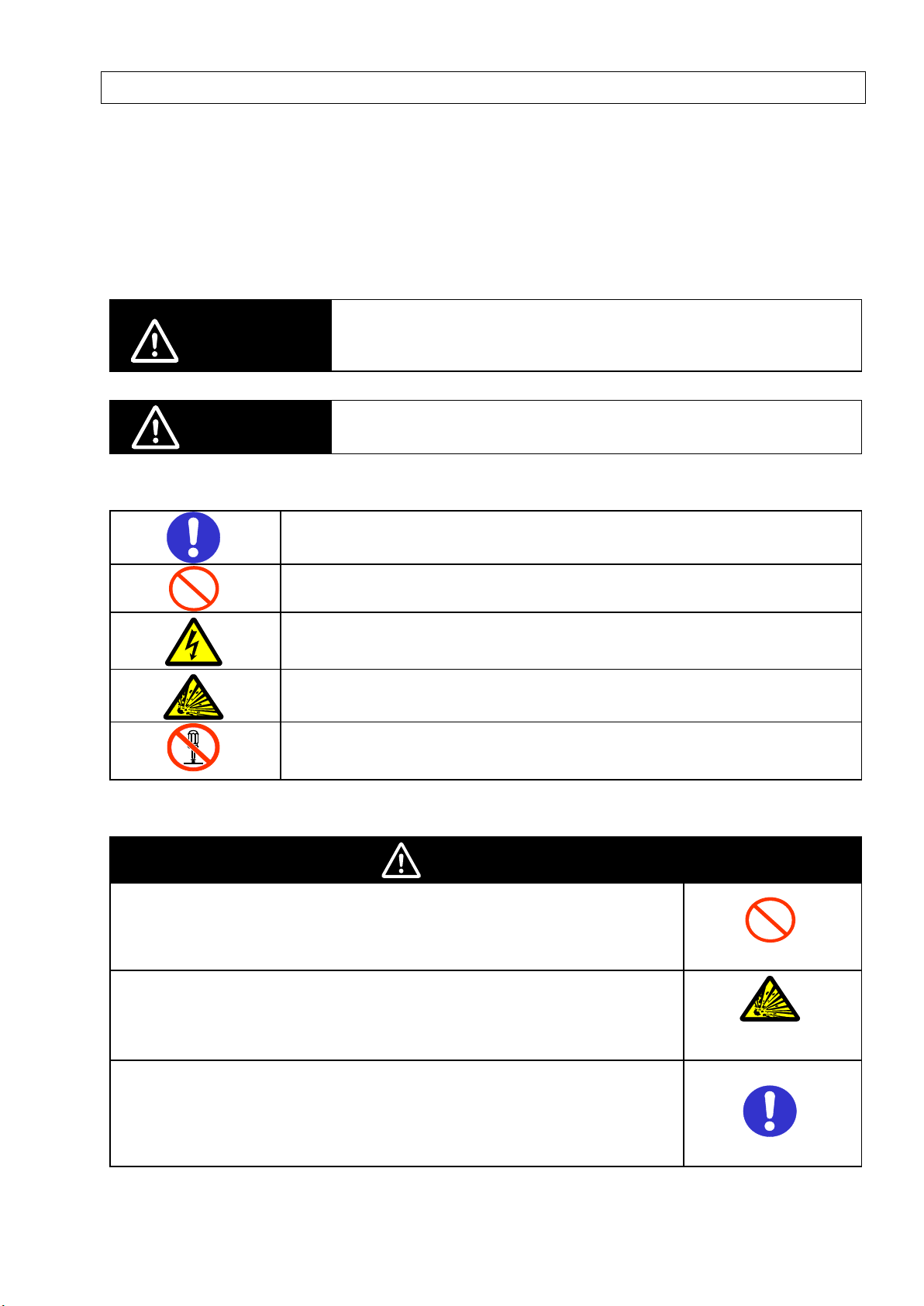
●Meaning of Precaution Symbols
●Mandatory Requirement
●Prohibition
Indicates general prohibition.
●Electric Shock Warning
Warns against an electric shock under specific conditions.
●Explosion Warning
Warns against an explosion under specific conditions.
●
●Warning Indications
WARNING
The mounting magnets provided with the product have strong magnetism. If
the product is mounted using these magnets, anyone wearing a heart
pacemaker must not operate the product; or the product must not be in
proximity of such a person.
This product contains lithium batteries. Serious injury may occur due to fire
or explosion. Do not attempt to disassemble the product, deform it by
applying pressure, heat it in a high temperature (100℃ or more), or burn it
for disposal.
The sensor head connector and the CT input circuit are not insulated. Do
not connect the dedicated CT terminal and connection cable directly to AC
or DC power supply. Extensive property damage, minor or moderate injury
connected directly to AC or DC power supply.
iv
Page 6
clamped to the
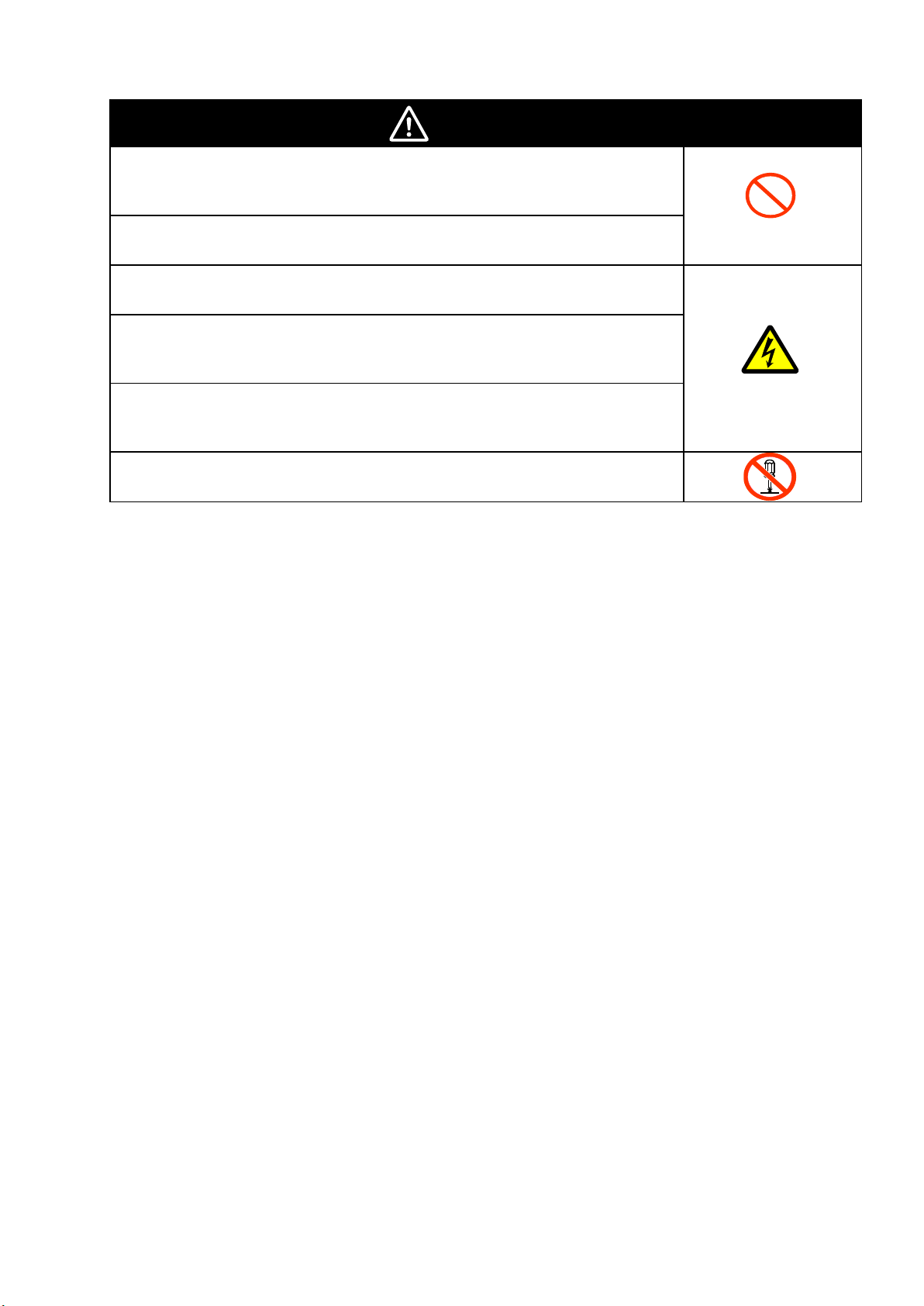
CAUTION
A minor or moderate injury or property damage may occur due to explosion.
Do not use the product in an environment containing an inflammable or
explosive gas.
An electric shock may occur. Do not replace the batteries when the unit is
clamped to a conductor for measurement.
An electric shock may occur. Do not remove or insert a sensor head from/to
the connector with the unit clamped to a conductor for measurement.
An electric shock may occur. Make sure that the power of a conductor to be
measured is turned OFF before clamping or detaching the unit to/from the
conductor. Or wear insulating gloves if the power is not turned OFF.
An electric shock may occur. Do not touch the terminal sections of the unit
and the conductor to be measured when the unit is
conductor.
An electric shock or minor injury as well as fire or unit malfunction may
occur. Do not attempt to disassemble, repair or modify the product.
v
Page 7

Precautions for Safe Use
Observe the following precautions to ensure safe operation:
・ Do not install the product in the places subject to exposure to water, oil, or chemical splashes.
・ Only the provided AC adapter (not other) must be used when using AC power supply.
・ If a voltage that exceeds the rated voltage is applied to the AC adapter, smoke may occur. Do not
connect a power supply that exceeds the rated voltage. In a situation where a voltage higher than the
rating is applied, use protective equipment so that the power supply voltage does not exceed the rated
voltage.
・ Dispose of the product as industrial waste.
・ Use batteries correctly, only after reading and being familiarized with the precautions provided by the
manufacturer.
・ Do not apply strong shock to the product, or it may cause damage or malfunction. It is recommended to
screw the product to mount it on the wall. Stop using the product when strong shock is applied.
・ When inserting or removing an SD card, the AC adapter, alarm output cable, or sensor connector,
securely hold the product to prevent it from dropping and being damaged.
・ Do not bring the product close to magnetic products (e.g. magnetic cards), sensitive electronics
equipment (e.g. computers or clocks), when the product is attached with the mounting magnets.
・ Small pieces may be chipped off the mounting magnets when they are attracted to the surface. Make
sure the pieces do not enter the eyes. Consult a medical doctor if this happens.
・ When using the mounting magnets to install the product, take caution not to allow a finger to be caught
between the product(s) and the magnetic surface.
・ Do not install the product at a high place when using the mounting magnets.
・ Apply an appropriate load to the alarm output terminals to prevent possible smoking.
・ If liquid crystal leaks due to a damage to the LCD panel, take caution not to allow it to contact your skin,
to be inhaled or swallowed. If it has contacted your skin or entered your mouth, seek medical attention.
・ Do not touch the Portable Power Monitor terminals as well as the sensor head connector and the
dedicated CT terminal when the unit is clamped to a conductor for measurement.
・ The product cannot be used for measurement of the secondary circuit of an inverter.
・ Take anti-static electricity measures (e.g. touching grounded metal object) when handling the product.
・ Only the dedicated CT specified by OMRON must be used.
Dedicated CT: ZN-CT-A
vi
Page 8
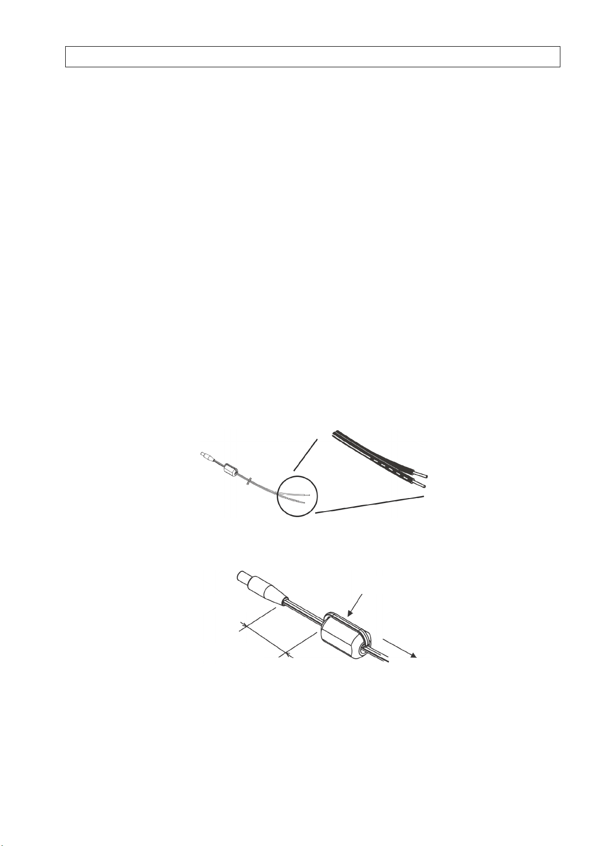
Single winding
Power supply
Device unit side
Approx. 100 mm
Precautions for Correct Use
1. Avoid installing the product in the following places:
・ Places exceeding the rated ambient temperature
・ Places exposed to extreme temperature changes (where condensation occurs)
・ Places subject to relative humidity exceeding the rated humidity range
・ Places subject to corrosive or flammable gases
・ Places subject to mist, droplets, coarse particles, fiber, salt, metal dust, or large amount of particles
・ Places subject to direct shock or vibration
・ Places subject to direct sunlight
・ Places subject to exposure to water, oil, or chemical splashes
・ Places subject to strong magnetic field or electric field
・ Outdoors
2. Wiring
・ Wire the product cable separately from high-voltage or power lines. Placing them in the same wiring or
the same duct may cause induction, resulting in the product malfunction or damage.
・ Make sure that the I/O terminals are inserted or removed with the power turned OFF. Doing this with the
power ON may result in a malfunction.
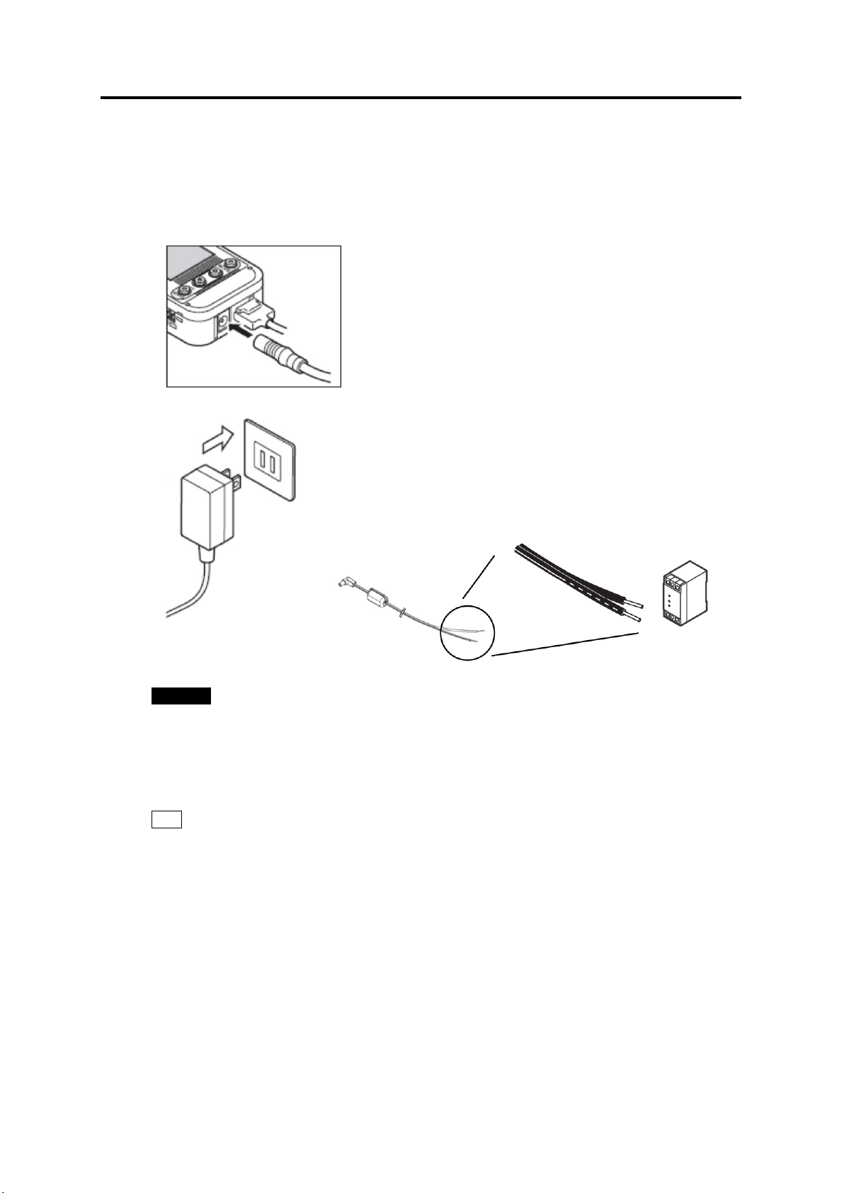
・ When using the provided DC cable, connect a wire with white line to the power supply (24 VDC±3%),
and connect a wire without the line to 0 V.
・ Mounting a ferrite core can reduce noise affecting to or affected by other devices when supplying power
with the DC cable. When using the provided DC cable, wind the provided ferrite core as shown below.
3. Battery use
・ Do not mix new and old batteries, or ones of different types or manufacturers. Doing so may result in the
product malfunction.
・ Do not install batteries in wrong polarities.
・ Always attach the battery cover during use. OMRON cannot be responsible for the product performance,
if the batteries accidentally drop off the product due to the unattached battery cover.
vii
Page 9

・ Remove the batteries when they are not used for a long time.
・ Used batteries remaining installed for a long time may leak and corrode in the product.
・ Do not disassemble or throw the battery into the fire.
・ When the battery level is low, the product may repeatedly restart. If this happens, replace the batteries
with new ones.
・ Use the AC adapter when operating the product through a network, since network connection rapidly
consumes batteries.
4. Battery disposal
・ Battery disposal must follow the guidelines provided by local governments. Dispose of batteries in
compliance with the relevant local regulations.
5. Mounting screw holes
・ The screw holes provided on the product are M3 and 4 mm deep. Do not screw deeper than 4 mm,
which may damage the product.
6. Measurement
・ Provide a distance of 20mm or more between the dedicated CT and the product when the mounting
magnets are used. Otherwise, measurement may be affected by the magnetism and therefore, may not
be correct.
・ Correct settings must be made specifically according to the object to be measured.
・ This product is not categorized as "a specified measuring instrument" officially approved by an
organization specified in relevant measurement acts. Therefore, the measured data provided by this
product cannot be used for official energy certificates.
viii
Page 10

・
How to Read This Manual
■
Symbols Used in this Manual
Menu items that are displayed on the screen, windows, dialog boxes and other GUI elements displayed on
the PC are indicated by brackets "[ ]".
Mar ks Used in this Manual
■
Important: Indicates essential information on the product operation and functions which requires special
attention or caution.
Note: Shows operational tips or related useful information.
ix
Page 11

Table of Contents
Introduction ................................................................................................................................................. i
Table of Contents ....................................................................................................................................... x
1. Product Overview ............................................................................................................................ 1-1
1.1 Features and Functions............................................................................................................... 1-1
(1) Portable Power Monitor for Easy Operation at Manufacturing Sites ...................................... 1-1
(2) Network Connection ............................................................................................................. 1-1
(3) Recording to an SD Memory Card ........................................................................................ 1-1
(4) Graph Display and Data Processing Software ...................................................................... 1-1
(5) Alarm Output........................................................................................................................ 1-2
(6) Backup Batteries .................................................................................................................. 1-2
(7) Auto-range Switch ................................................................................................................ 1-2
(8) High-speed Logging ............................................................................................................. 1-2
1.2 Configuration .............................................................................................................................. 1-3
1.2.1 Standalone ........................................................................................................................... 1-3
1.2.2 Network Connection ............................................................................................................. 1-3
(1) Remote Setting and Operation from PC ............................................................................... 1-3
(2) Measured Data Acquisition to PC ......................................................................................... 1-3
1.3 Easy Power Measurement .......................................................................................................... 1-4
1.4 Setup and Operation Procedure .................................................................................................. 1-5
1.4.1 Standalone Operation........................................................................................................... 1-5
1.4.2 Operation via Network .......................................................................................................... 1-6
2. Part Name and Function .................................................................................................................. 2-1
2.1 Display Unit................................................................................................................................. 2-1
2.2 Control Unit ................................................................................................................................. 2-3
2.2.1 Control Key .......................................................................................................................... 2-3
2.2.2 Reset Switch ........................................................................................................................ 2-3
2.2.3 Inserting/Removing SD Card ................................................................................................ 2-3
(1) Inserting SD Card ................................................................................................................ 2-4
(2) Removing SD Card .............................................................................................................. 2-4
2.3 Input/Output Specifications .......................................................................................................... 2-5
2.3.1 Alarm Output........................................................................................................................ 2-5
(1) Alarm Output Terminals ........................................................................................................ 2-5
(2) Output Specifications ........................................................................................................... 2-5
3. Check and Preparation .................................................................................................................... 3-1
3.1 Checking the Package Contents.................................................................................................. 3-1
3.2 Preparing the Required Items ...................................................................................................... 3-1
(1) Common .............................................................................................................................. 3-1
(2) Network Connection ............................................................................................................. 3-1
3.3 Configuring the Unit .................................................................................................................... 3-2
3.3.1 Connecting Dedicated CT .................................................................................................... 3-2
3.3.2 Using Alarm Function ........................................................................................................... 3-2
3.3.3 Preparing Power Supply ....................................................................................................... 3-3
(1) Connecting to External Power Supply ................................................................................. 3-3
(2) Using Batteries..................................................................................................................... 3-4
3.3.4 Checking Operation ............................................................................................................. 3-5
3.4 Station Utility PC Software Overview and Preparation.................................................................. 3-6
x
Page 12

3.4.1
Overview.............................................................................................................................. 3-6
(1) Setting Tool .......................................................................................................................... 3-6
(2) Logging Tool ........................................................................................................................ 3-6
(3) Momentary Value Display (SD Viewer ES)............................................................................ 3-6
(4) Integration and Summation Tool (Energy Viewer) ................................................................. 3-6
3.4.2 Installation............................................................................................................................ 3-6
3.5 Setting the Measurement Conditions ........................................................................................... 3-7
(1) Switching to "FUN" Mode ..................................................................................................... 3-7
(2) Setting the Number of Channels to Use (USECH) (Example: 2 Channels) ............................ 3-7
(3) Setting Measurement Target Circuit (TYPE) and Dedicated CT Type (CT) ............................ 3-8
(4) Setting Voltage of Measurement Target (VOLT) (Example: 100.0V) ...................................... 3-8
(5) Setting Power Factor (PF) and Frequency (FREQ) ............................................................... 3-8
3.6 Connecting to Network ................................................................................................................ 3-9
3.6.1 Preparation .......................................................................................................................... 3-9
3.6.2 Setting Portable Power Monitor IP Address ........................................................................ 3-10
(1) Switching to "FUN" Mode ................................................................................................... 3-10
(2) Setting ETC and IP to “DISP” ..............................................................................................3-11
(3) Changing IP Address (from factory default: 192.168.0.20 to 192.168.0.21) ......................... 3-12
3.6.3 Setting the PC IP Address .................................................................................................. 3-13
(1) Windows XP ...................................................................................................................... 3-13
(2) Windows Vista ................................................................................................................... 3-16
(3) Windows 7 ......................................................................................................................... 3-19
3.6.4 Connecting LAN Cable ....................................................................................................... 3-22
3.7 Mounting the Unit ...................................................................................................................... 3-23
3.7.1 Free-stand Installation ........................................................................................................ 3-23
3.7.2 Securing with Mounting Magnets ........................................................................................ 3-23
3.7.3 Securing with Mounting Screws .......................................................................................... 3-24
3.7.4 Screw Hook Mounting ........................................................................................................ 3-24
3.8 Attaching Dedicated CT to Measurement Target ........................................................................ 3-25
4. Setting the Unit (Unit Operation) ..................................................................................................... 4-1
4.1 Setting Procedure and Operation Modes ..................................................................................... 4-1
4.2 Settings (FUN Mode Operation) .................................................................................................. 4-2
4.2.1 Setting Item List ................................................................................................................... 4-2
4.2.2 Selecting "FUN" Operation Mode ......................................................................................... 4-5
4.2.3 Selecting Items .................................................................................................................... 4-6
4.2.4 Definition of Items ................................................................................................................ 4-7
(1) Ranking Clear (CLEAR) ....................................................................................................... 4-7
(2) Recording Interval (CYCLE) ................................................................................................. 4-7
(3) Timer Setting (TIMER) ......................................................................................................... 4-8
(4) St art Tr igger (STRIG) ........................................................................................................... 4-8
(5) Start Time (STIME)............................................................................................................... 4-9
(6) End Trigger (ETRIG) ............................................................................................................ 4-9
(7) End Time (ETIME).............................................................................................................. 4-10
(8) Elapsed Time (ELPSD) ...................................................................................................... 4-10
(9) Measurement Mode (MODE)...............................................................................................4-11
(10) Recording Mode (REC) ...................................................................................................... 4-12
(11) Integrated Power Reset Interval (INTEG) ........................................................................... 4-12
(12) The Number of Channels to Use (USECH) ......................................................................... 4-13
(13) Measurement Target Circuit (TYPE) ................................................................................... 4-13
(14) Dedicated CT Type (CT)..................................................................................................... 4-13
(15) Voltage of Measurement Target (VOLT) .............................................................................. 4-13
(16) Power Factor (PF) .............................................................................................................. 4-14
(17) Frequency (FREQ) ............................................................................................................. 4-14
(18) Initialization (INIT) .............................................................................................................. 4-14
(19) Others (ETC) ..................................................................................................................... 4-15
(20) Reading Setting Data (RESTR) .......................................................................................... 4-15
(21) Writing the Setting Data (BCKUP) ...................................................................................... 4-16
xi
Page 13

(22)
Time Setting (CLOCK) ....................................................................................................... 4-16
(23) YEAR/MONTH/DAY/TIME Setting ...................................................................................... 4-17
(24) Network Setting (NET) ....................................................................................................... 4-17
(25) Setting IP Address (IP) ....................................................................................................... 4-17
(26) IP Address and Subnet Mask (IP 1 to IP 4, SUB 1 to SUB 4) .............................................. 4-18
(27) DTA I L ................................................................................................................................ 4-18
(28) Rated Primary Side Current Value (SCT5A) ....................................................................... 4-18
(29) Zero-out Low Current Value (LOCUT) ................................................................................ 4-19
(30) Measurement Range (RANGE) .......................................................................................... 4-19
(31) Rate/CO2 Conversion Value Setting (RATE) ....................................................................... 4-20
(32) Conversion Unit Setting (CONV) ........................................................................................ 4-20
(33) Power Startup REC Restoration (REREC) .......................................................................... 4-20
4.2.5 Changing the Set Value ...................................................................................................... 4-21
(1) Changing Option Type Item Values (Example: CYCLE) ...................................................... 4-21
(2) Changing Numeric Input Type Item Value (Example: YEAR) ............................................... 4-22
4.3 Settings (THR Mode Operation) ................................................................................................ 4-23
4.3.1 Setting Item List ................................................................................................................. 4-23
4.3.2 Selecting "THR" Operation Mode ....................................................................................... 4-24
4.3.3 Selecting Items .................................................................................................................. 4-24
4.3.4 Definition of Items .............................................................................................................. 4-25
(1) Upper Limit Threshold of kWh or Higher Integrated Power (INT H) ..................................... 4-25
(2) Upper Limit Threshold of Less than kWh Integrated Power (INT H)..................................... 4-25
4.3.5 Changing the Set Value ...................................................................................................... 4-25
4.4 Copying Setting Data for Multiple Monitor Units ......................................................................... 4-25
5. Measurement and Recording (Unit Operation) ............................................................................... 5-1
5.1 Over view..................................................................................................................................... 5-1
5.2 Selecting Operation Mode ........................................................................................................... 5-1
5.3 Screen Transition in RUN Mode .................................................................................................. 5-2
5.4 Starting/Stopping Recording ........................................................................................................ 5-5
5.4.1 Starting Recording................................................................................................................ 5-5
5.4.2 Stopping Recording .............................................................................................................. 5-5
5.5 SD Outputting File to SD Memory Card ....................................................................................... 5-6
5.6 Cancelling Retained Alarm .......................................................................................................... 5-6
5.7 Display Turning OFF ................................................................................................................... 5-6
6. Ratings and Performance ................................................................................................................ 6-1
Appendix .................................................................................................................................................... 1
Error Display List ...................................................................................................................................... 1
Character Display List .............................................................................................................................. 2
SD Memory Card Folder Structure ............................................................................................................ 3
Calibration ................................................................................................................................................ 4
Installation Diagram .................................................................................................................................. 5
Revision History6-0
xii
Page 14

1. Product Overview
1. Product Overview
1.1 Features and Functions
(1) Portable Power Monitor for Easy Operation at Manufacturing Sites
The ZN-CTX21 Portable Power Monitor provides simplified wiring operation and measurement
of power consumption (converted values) without stopping lines. Power data acquisition at
operation sites now becomes easy, contributing to enhanced energy-saving efficiency.
(2) Network Connection
The measured values obtained from multiple Portable Power Monitor units can be acquired to
a PC connected to the units via LAN cable by using the PC software. The individual Portable
Power Monitors can be controlled from the PC to check or change their settings as well as
start/stop the recording. (Refer to "Station Utility User's Manual" for details.)
Online real-time control of the entire network is also possible from the PC by using Wave
Inspire ES, separately sold software.
(3) Recording to an SD Memory Card
The measured data can be recorded in the Portable Power Monitor. Up to approx. 6500 data
items* can be accumulated in the internal memory, which enables the monitor to continue data
recording even at an emergency network failure. The monitor allows its data accumulated in
the internal memory to be output to an SD memory card in CSV format without stopping
measurement. The data can be loaded and controlled on the PC.
* The internal memory can store the data continuously for approx. 105 minutes at the
standard recording interval (1 second). Use an SD memory card for longer time of
recording.
(4) Graph Display and Data Processing Software
The data output to an SD card or acquired to a PC through LAN connection can be displayed
in graphs or processed online by using the PC software. The data items in different periods
can be combined or data from multiple monitor units can be displayed simultaneously top to
bottom on the screen. (Refer to "Station Utility User's Manual" for details.)
1-1
Page 15

1. Product Overview
(5) Alarm Output
Alarm output terminals are provided on the Portable Power Monitor. The alarm is output when
the integrated power value exceeds the upper limit. This feature provides 'visualization' of the
power limit, allowing the operator to quickly handle problems. (Available in the NORM and
HISPD measurement operation modes)
(6) Backup Batteries
This product provides an uninterruptible power supply consisting of two AAA batteries, which
prevents recording operation from being stopped even at an accidental power outage or
failure. Rechargeable nickel-metal hydride cells or alkaline dry cells can be used.
*1: Battery life depends on the measurement environment and conditions as well as the
battery type and performance.
(7) Auto-range Switch
The Portable Power Monitor provides two measurement ranges: Normal and Small for each
dedicated CT type. The monitor can automatically switch the measurement range to a
small-scale range when the measured power level becomes approx. 5% or below the rat ed
current. Highly precise low power level measurement is possible.
(8) High-speed Logging
The Portable Power Monitor can provide the dedicated mode for more detailed measurement
recording.
The measurement recording speed can be selected between 100ms at 50Hz or 83ms at 60Hz,
which facilitates detailed analysis of power consumption changes (When the measurement
mode is set to HISPD).
*2: Network functions cannot be used during high-speed logging.
1-2
Page 16
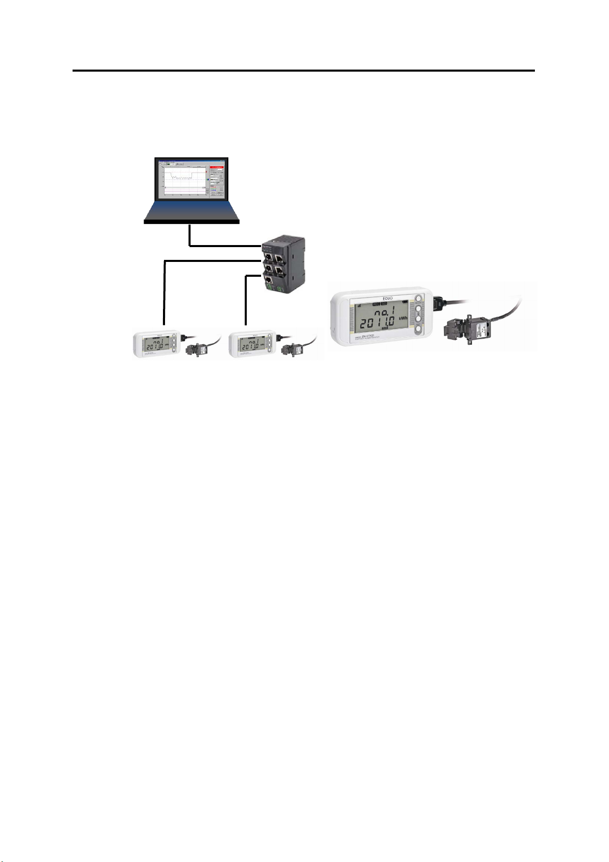
1.2 Configuration
Network Connection
PC
LAN Cable
This product can be used in the following two types of configuration.
1.2.1 Standalone
1. Product Overview
HUB
Standalone
Portable Power Monitors can be operated standalone without connecting them to a network.
The measured data is recorded in the internal memory and can be loaded to a PC via an SD
card. The recorded data in an SD card can be displayed in graphs using SD Viewer ES or
Energy Viewer, software included in Station Utility. (Refer to "Station Utility User's Manual" for
the PC software details.)
1.2.2 Network Connection
Portable Power Monitors can be connected to a PC via LAN. The following operations are
available by using the PC software. (Refer to "Station Utility User's Manual" for the PC
software details.)
(1) Remote Setting and Operation from PC
Settings on Portable Power Monitors (except for IP address settings) and recording start/stop
operation can be controlled remotely from the PC by using the Station Utility (PC software )
setting tool.
(2) Measured Data Acquisition to PC
The measured data on Portable Power Monitors can be acquired to the PC using the Station
Utility (PC software) logging tool. The acquired data can be displayed in graphs offline on SD
Viewer ES or Energy Viewer included in Station Utility.
1-3
Page 17

1.3 Easy Power Measurement
The Portable Power Monitor displays the measured momentary power during the power
is ON.
The monitor measures electric current values, which are then multiplied by a specified
voltage and power factor (the ratio of effective power) to convert them into power values.
A long press of the SET/REC/STOP key measures and displays an integrated power
consumption.
Another long press of the SET/REC/STOP key stops recording and the integrated power
value up to that moment is displayed as a record in the ranking from the highest to
lowest integrated power values. (Ranking Function)
Up to 9 value records can be logged in the ranking. When the 10th record is added, the
lowest integrated power value is deleted.
The ranking can be cleared using the CLEAR menu item.
The integral power consumption reset function is also available, which enables the
operator to analyze the peak power by only using the monitor unit.
1. Product Overview
1-4
Page 18

1.4 Setup and Operation Procedure
3.1 Checking the Package Contents
3.2 Preparing the Required Items
3.3 Configuring the Unit
4 Setting the Unit (Unit Operation)
"Station Utility User's Manual": 1. Overview and Preparation
5 Measurement and Recording (Unit Operation)
"Station Utility User's Manual": 4. Momentary Value Display
3.5 Setting the Measurement Conditions
⇒"Station Utility User's Manual": 5. Integration and Summation
3.7 Mounting the Unit
3.8 Attaching Dedicated CT to Measurement Target
1.4.1 Standalone Operation
Check the package contents
⇒
Check the required items
⇒
Connect the sensor head, alarm output terminals and prepare the power supply
⇒
Install the Station Utility PC software
⇒
Set the measurement conditions
⇒
Mount the product
⇒
Attach the dedicated CT
⇒
Make settings directly on the unit
⇒
Record data by direct unit operation
⇒
Analyze short-period recording data
⇒
Analyze long-period recording data
1. Product Overview
1-5
Page 19

1.4.2 Operation via Network
"Station Utility User's Manual": 4. Momentary Value Display
3.1 Checking the Package Contents
3.2 Preparing the Required Items
3.3 Configuring the Unit
3.6 Connecting to Network
3.7 Mounting the Unit
"Station Utility User's Manual": 1. Overview and Preparation
3.5 Setting the Measurement Conditions
"Station Utility User's Manual": 5. Integration and Summation
"Station Utility User's Manual": 2.
Remote Setting and Operation
Control from PC
3.8 Attaching Dedicated CT to Measurement Target
Check the package contents
⇒
Check the required items
⇒
Connect the sensor head, alarm output terminals and prepare the power supply
⇒
Install the Station Utility PC software
⇒
Set the measurement conditions
⇒
Connect the product to a network
⇒
Mount the product
⇒
Attach the dedicated CT
⇒
Record data to PC
⇒"Station Utility User's Manual":
3. Recording to PC
Analyze short-period recording data
⇒
Analyze long-period recording data
⇒
1. Product Overview
Remotely record data to the unit
⇒
1-6
Page 20
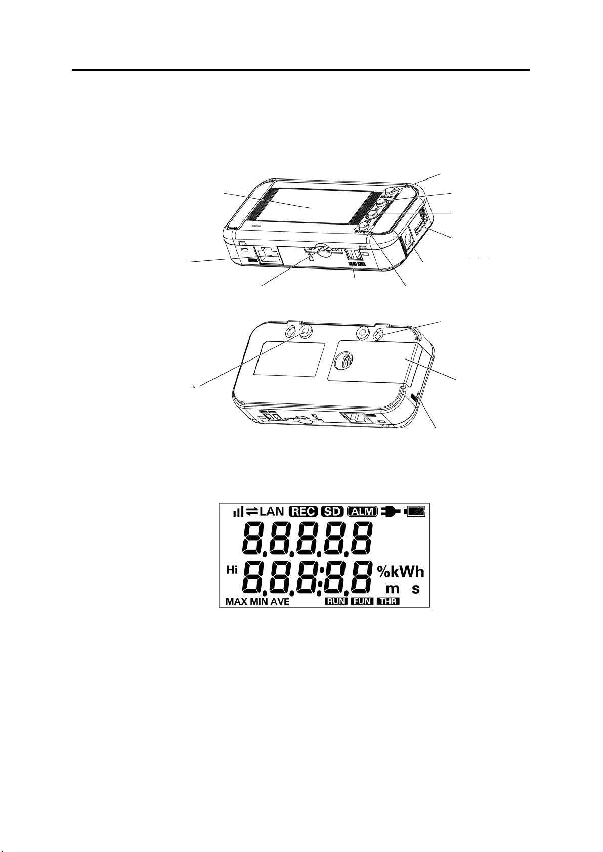
2. Part Name and Function
AC Adapter Terminal
Mounting Screw Hole
Reset Switch
2. Part Name and Function
MODE Key
Display Unit
LAN Port
SD Card Slot
△ Key
▽ Key
Sensor Head Connector
SET/REC/STOP Key Alarm Output Terminals
Screw Hook Hole
Battery Cover
2.1 Display Unit
Display Unit
2-1
Page 21
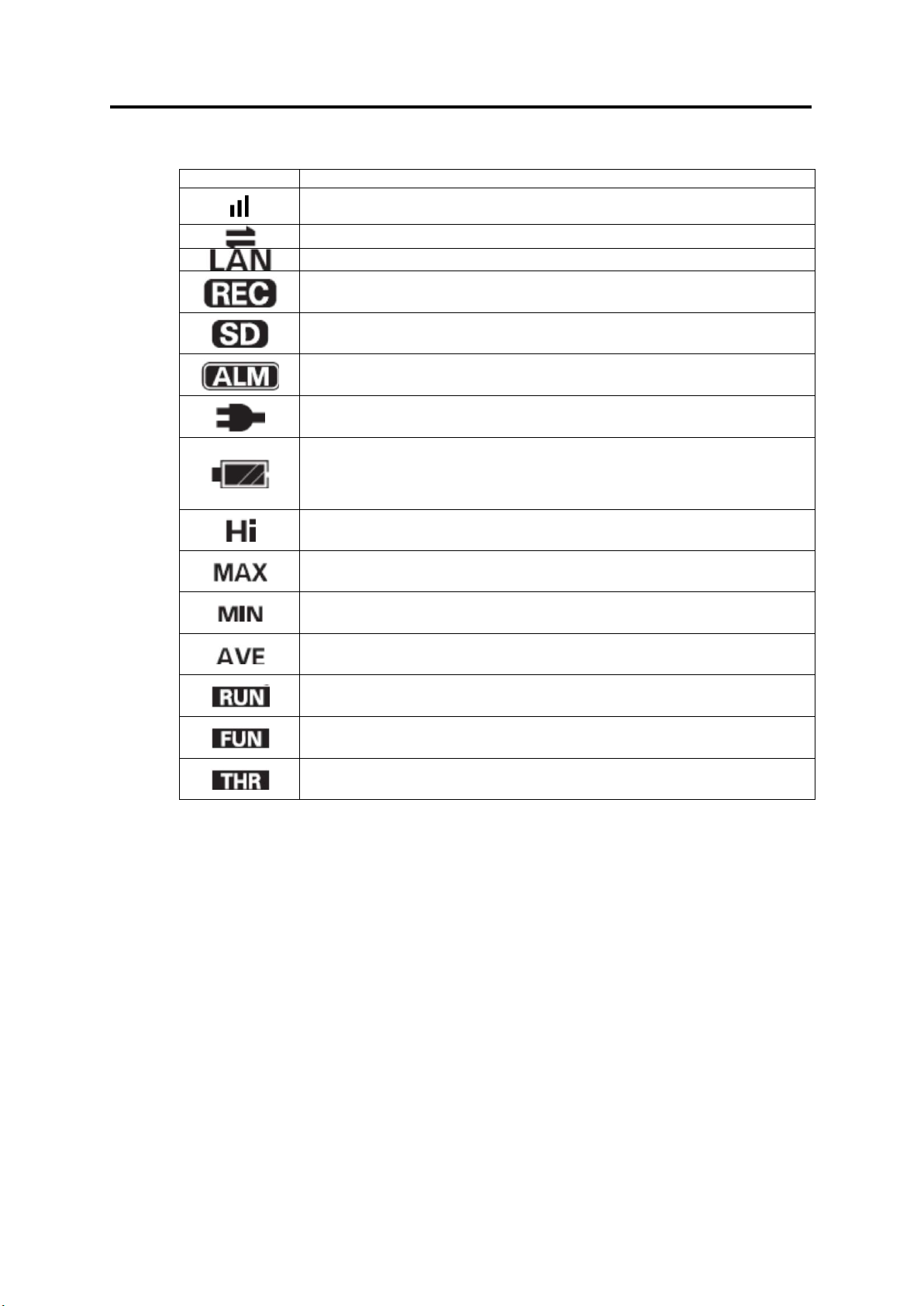
2. Part Name and Function
Display
Definition/Function (When Displayed)
An Integral power consumption reset interval is set.
The setting is OFF when this is not displayed.
Communication via LAN cable is in process.
A LAN cable is connected and network communication is ready.
Data is being recorded in the internal memory.
threshold value.
The battery level is shown in 4 levels. Replace the batteries when this is
in NORM or HISPD.
Indicator Definition
Blinking: The timer is set for the unit to wait for recording start.
An SD memory card is inserted.
Blinking: The SD card is being accessed.
An integral power consumption has exceeded the specified upper
Power is being supplied to the unit.
blinking.
This indication is not available when the measurement mode (MODE) is
Indicates the upper limit threshold value.
Indicates the maximum momentary power value.
Indicates the minimum momentary power value.
Indicates the average momentary power value.
The unit is currently operating in RUN mode.
The unit is currently operating in FUN mode.
The unit is currently operating in FUN mode.
Refer to the Appendix for the definitions of alphabetical, numeric and principal message
displays.
Refer to: Appendix, "Character Display List"
2-2
Page 22

2.2 Control Unit
Name
Function
Switches the operation mode.
Cancels the setting before applying it.
Item Selection Key
Moves the setting items (Upward).
Changes the setting value (Incremental).
Item Selection Key
Moves the setting items (Downward).
Changes the setting value (Decremental).
Applies the setting value or changes.
Saves the recorded data to the SD memory card.
2.2.1 Control Key
2. Part Name and Function
MODE Key
(△ Key)
(▽ Key)
SET/REC/STOP Key
Resets an alarm or error (Long press).
Switches the display.
Switches the display.
Starts/stops recording (Long press).
2.2.2 Reset Switch
The reset switch is provided inside the aperture on the unit left side. Use a thin wire or
similar object to press the switch. The unit resets itself.
Do not touch the front keys when the unit is in reset process, until the power indication is
displayed.
Reset operation does not initialize the settings made on the unit.
2.2.3 Inserting/Removing SD Card
This product provides an SD card slot for SD memory card operation such as writing the
measured data recorded in the internal memory to the card, and writing/reading the setting
data to/from the card.
Important
・Secure the unit firmly when inserting/removing an SD card. It is essential especially when
the unit is mounted using the screw hook holes. If the card is inserted/removed without
securing the unit, the unit may be detached from the hooks and drop on the floor, damaging
itself.
・Do not remove the SD card when the "SD" display is blinking. Doing so may destroy the
data in the SD card.
・Do not touch the metal terminal of the SD card.
・Make sure that the SD card does not bend.
・Avoid static electricity when inserting/removing an SD card.
・Do not enable the write-protection of the SD card.
2-3
Page 23

2. Part Name and Function
"SD" turns ON
Click!
(1) Inserting SD Card
「SD」点灯
(1) Insert an SD card into the SD card slot with the
metal terminal facing up.
(2) Push the card inward until it clicks.
(3) “SD” appears on the display.
(2) Removing SD Card
(1) Push the inserted SD card inward until it clicks.
(2) Stop pushing and let the card pops out. Take caution not to drop the card.
(3) “SD” on the display disappears.
2-4
Page 24
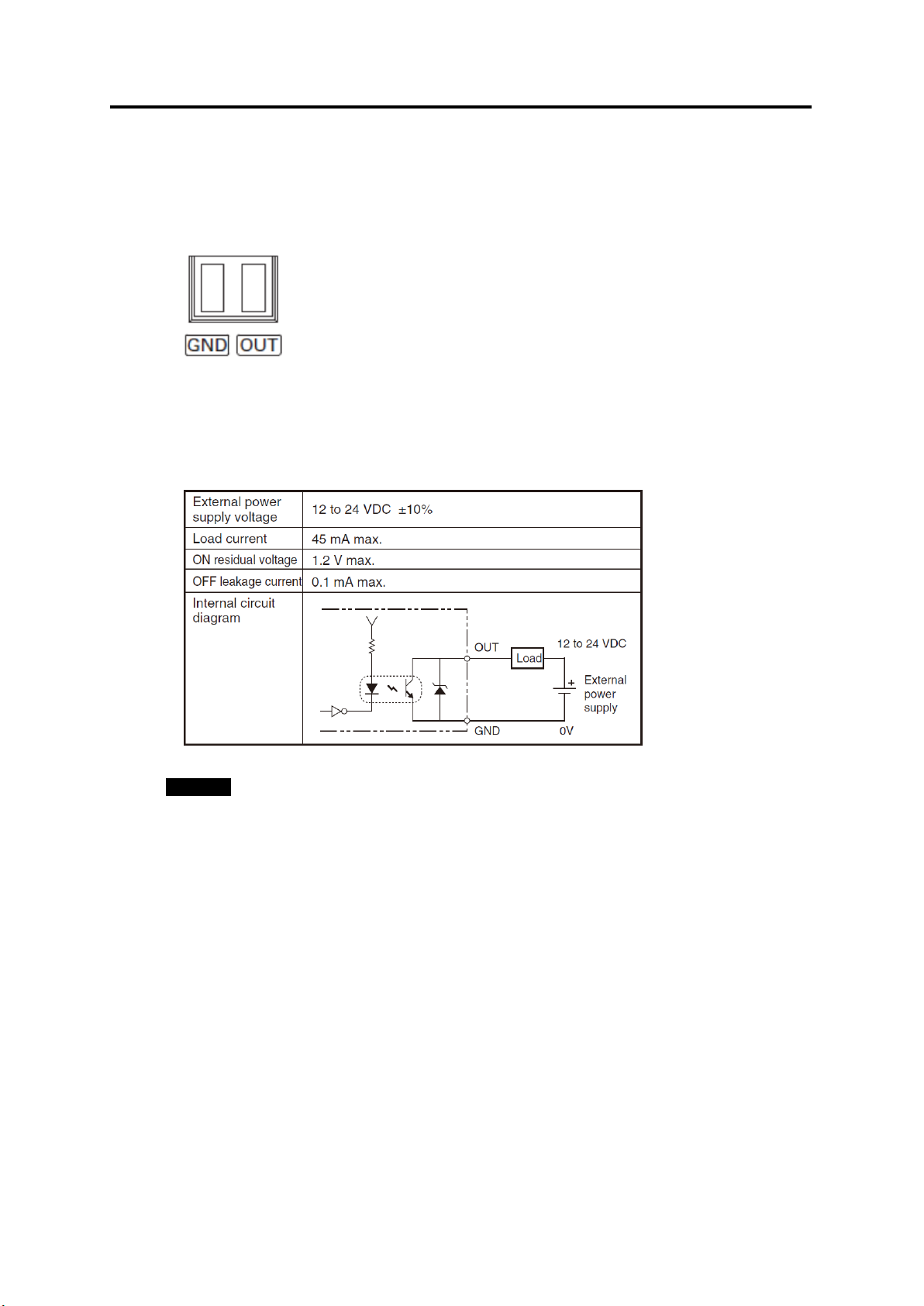
2.3 Input/Output Specifications
2.3.1 Alarm Output
(1) Alarm Output Terminals
(1) OUT
Outputs the judgment result allocated in THR mode.
(2) GND
It is a common terminal.
The terminal names are inscribed on the unit.
Use the provided alarm output connector for wiring.
(2) Output Specifications
2. Part Name and Function
Important
・Do not connect the external power supply directly between OUT and GND.
Note that it must be connected through a load.
・An alarm cannot be output when the measurement mode (MODE) is set to "SLEEP".
2-5
Page 25

3. Check and Preparation
3.1 Checking the Package Contents
This product package includes the following items:
□Main Unit ZN-CTX21
□AC Adapter or DC cable 1
□Alarm Output Connector 1
□Instruction Sheet 1
□Startup Guide 1
□Mounting Magnet (Pre-installed) 2
3.2 Preparing the Required Items
The following items are required to use this product.
1
3. Check and Preparation
(1) Common
□Dedicated CT: ZN-CT1-A 1 (Separately sold)
Up to three units can be connected when using a branch cable (ZN-CTM11-C)
□PC (personal computer) for the PC software 1
Refer to: 3.4.2 Operating Environment
□SD Memory Card (SDHC compatible) 1 (Recommended: HMC-SD291, 2 GB)
Used to save measured data or to relocate the data (when recording in a Portable Power
Monitor unit)
□AAA batteries (when using battery power supply) 2
Alkaline dry cells or nickel-metal hydride cells (Ni-MH)
Important
Manganese battery cells cannot be used.
Use two batteries of the same type. Do not mix new and used batteries.
(2) Network Connection
□LAN Cable (10BASE-T or 100BASE-TX; Safety Category 5e or higher; Straight Type)
□LAN Connection HUB (for 10BASE-T or 100BASE-TX)
Note
Generally, Portable Power Monitors should be connected to a PC via a HUB.
3-1
Page 26
3.3 Configuring the Unit
Click!
3.3.1 Connecting Dedicated CT
The separately sold dedicated CT of ZN-CT□□1-□A or ZN-CTM-A CT is required to
use this product.
Insert the dedicated CT in the sensor head connector until it clicks.
Important
A branch cable (ZN-CTM11-C) is required when using ZN-CTM-A. For connecting
method, refer to the instruction sheet of ZN-CTM-A.
Do not insert or remove the CT unit to/from the sensor head connector when a conductor
for measurement is clamped.
Do not insert or remove the sensor head to/from the connector when the unit power is
ON.
The dedicated CT may be damaged if either of the above happens.
3.3.2 Using Alarm Function
3. Check and Preparation
Use the provided alarm output connector to connect the OUT and GND alarm output
terminals to the load according to the output specifications.
Refer to: 2.3.1 Alarm Output
3-2
Page 27
3. Check and Preparation
DC Power Supply
AC Adapter
3.3.3 Preparing Power Supply
An external power supply or batteries can supply power to this product.
(1) Connecting to External Power Supply
(1) Insert the AC adapter or DC cable plug into the power
supply terminal on the unit.
(2) Connect the AC plug of the AC adapter to an outlet (100 VAC
to 240 VAC) when using AC power supply. To use DC power
supply, connect the white-lined wire of the DC cable to the
power input (24 VDC±10%) and the non-lined wire to 0V.
Important
・Use the provided AC adapter when using AC power supply.
・Use the provided DC cable when using DC power supply.
・Do not use batteries when connecting the unit to a network. (Batteries are rapidly
consumed.)
Note
・A power switch is not provided on the unit. The unit starts operation immediately when the
power is supplied.
・The external power supply is normally used as the primary power source when both
external power supply and batteries are provided in the configuration. Batteries are used
when the external power supply fails due to power outage or other reason. The unit
automatically switches to the battery supply in such an event provided the batteries are
mounted in the unit.
3-3
Page 28
3. Check and Preparation
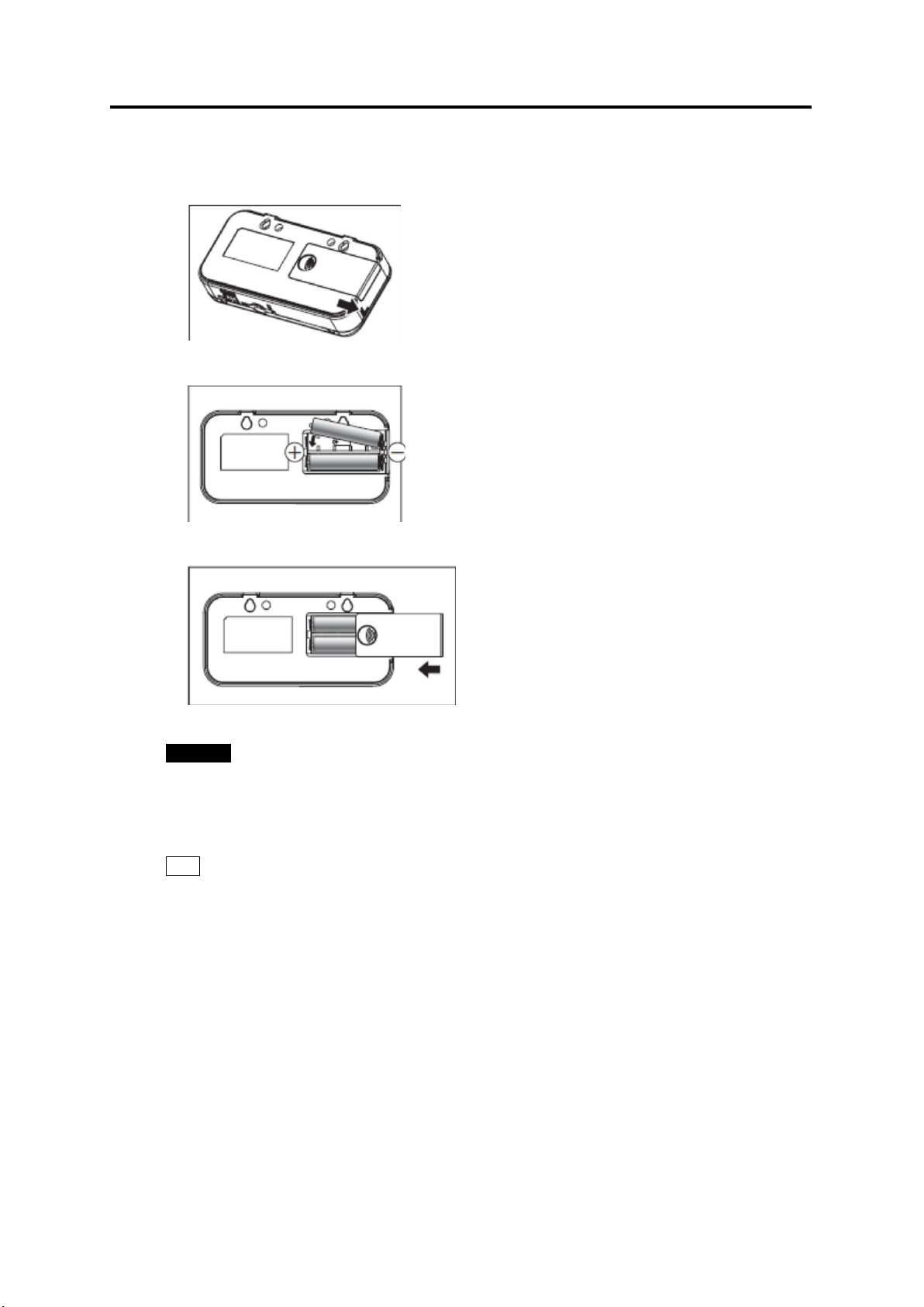
(2) Using Batteries
(1) Slide the battery cover off the rear side of the
unit.
(2) Mount two batteries to the correct polarities in
the battery compartment.
(3) Slide the battery cover on to close the battery
compartment.
Important
・Take caution not to insert the batteries in the wrong polarities. The unit may be damaged if
this happens.
・Use two batteries of the same type and model. Do not mix new and used batteries.
Note
・It is recommended that the SLEEP measurement mode is entered when using battery
power supply.
・The AC adapter is used as the primary power source when both AC adapter and batteries
are connected to the unit. The unit automatically switches to the battery source when the
AC power supply is discontinued due to power failure or other reason.
・A power switch is not provided on the unit. The unit starts operation immediately after the
batteries are installed.
・Rechargeable batteries (if they are used) must be charged prior to use. The unit does not
provide a battery charging feature.
3-4
Page 29

3.3.4 Checking Operation
After the power is turned ON, the type name and version are displayed for a while. Then,
the power information appears on the display.
Press ▽ or △ keys to change the display while the "RUN" indicator at the bottom of the
display is ON.
Refer to: 5.3 Screen Transition in RUN Mode
Important
Do not touch the front keys until the power information appears on the display after the
power is ON.
3. Check and Preparation
3-5
Page 30

3. Check and Preparation
3.4 Station Utility PC Software Overview and Preparation
3.4.1 Overview
Station Utility PC software consists of four principal functions. Refer to "Station Utility User's
Manual" for details.
(1) Setting Tool
This function provides remote operations including measurement condition settings (except
for some settings), recording start and stop on the PC for remotely located Portable Power
Monitors.
(2) Logging Tool
The function acquires the measured data from Portable Power Monitors to the PC via
network.
The measured data in the monitors also can be displayed on the PC.
(3) Momentary Value Display (SD Viewer ES)
The tool provides the graph displays offline of the data acquired to the PC using the logging
tool or the Portable Power Monitor data recorded to the SD memory card. It can also combine
multiple data items recorded in different periods or provide a concurrent display of multiple
data items recorded in different periods or with different Portable Power Monitors. Detailed
power value changes in interaction with other devices at the operation site can be observed.
(4) Integration and Summation Tool (Energy Viewer)
The tool provides summations of data acquired to the PC using the logging tool or Portable
Power Monitor data recorded to the SD memory card. The unit of summation periods can be
changed and pre-selected summation items on multiple Portable Power Monitor units can be
displayed in graphs with this tool. It also provides the comparison of the current data with past
summation data. Longer-term (e.g. daily or monthly) power value changes at the operation
site can be observed.
3.4.2 Installation
Install Station Utility on the PC.
Refer to "Station Utility User's Manual": 1.3 Operating Environment and 1.4 Installation, for
the installation procedure.
3-6
Page 31

3.5 Setting the Measurement Conditions
Press the ▽or △ key until "USECH" appears at the upper row on
↓
or △ Key
Check if "2CH" is displayed at the lower row. If it is displayed, the
The lower row indication starts blinking.
↓
USECH
Blinking
↓
or △ Key
USECH
Blinking
Press the SET/REC/STOP key to apply "2CH" for the number of
↓
Next, proceed to the measurement target circuit type (TYPE) and
MODE Key
Set the measurement conditions for the object to measure. The measurement conditions
include six items: the number of channels to use (USECH), the measurement target circuit
(TYPE), the dedicated CT type (CT), the voltage of the measurement target (VOLT), power
factor (PF) and frequency (FREQ).
Note
Refer to the sections below for details on messages displayed on the display unit and
operational key functions.
Refer to: 2.1 Display Unit, 2.2 Control Unit, and 4.2 Setting (FUN Mode Operation)
(1) Switching to "FUN" Mode
"FUN" mode should be entered for setting measurement conditions. Press the MODE key
until the "FUN" indicator at the right of the display starts blinking.
RUN Mode
Twice
FUN M ode
"FUN" Blinking
MODE Key
3. Check and Preparation
MODE Key
THR Mode
(2) Setting the Number of Channels to Use (USECH) (Example: 2 Channels)
CLEAR
("FUN" Blinking)
▽
USECH
2CH
SET/REC/STOP Key
1CH
↑
▽
2CH
↑
SET/REC/STOP Key
USECH
2CH
the display.
number of channels has been already set to "2", and no other
setting is required.
If the above is not displayed, press the SET/REC/STOP key.
Press the ▽or △ key to display "2CH" at the lower row.
channels to use. The blinking at the lower row stops.
dedicated CT type (CT) settings.
3-7
Page 32

3. Check and Preparation
Display
(Upper/Lower)
Operation
Press the ▽or △ key until "VOLT" appears at the upper row on
↓
VOLT
220.0
Press the SET/REC/STOP key. The lower row indication starts
blinking.
↓SET/REC/STOP Key
VOLT
Blinking
Press the ▽or △ key to display "100.0" at the lower row.
key can rapidly change the
values in Decremental or incremental steps.
↓
VOLT
Blinking
Press the SET/REC/STOP key to apply "100.0" for the
↓
Next, proceed to the power factor (PF) and frequency (FREQ)
(3) Setting Measurement Target Circuit (TYPE) and Dedicated CT Type (CT)
Set the measurement target circuit (TYPE) and dedicated CT type (CT) in the same way as
the previous setting.
Refer to the FUN mode description for the measurement target circuit and dedicated CT
type details.
Reference: 4.2.4 (13) Measurement Target Circuit (TYPE), 4.2.4 (14) Dedicated CT Type
(CT)
(4) Setting Voltage of Measurement Target (VOLT) (Example: 100.0V)
CT
200A
("FUN" Blinking)
▽or △ Key
220.0
↑
▽or △ Key
100.0
↑
SET/REC/STOP Key
VOLT
100.0
the display.
Note A long press of the ▽ or △
measurement target voltage. The blinking at the lower row stops.
settings.
(5) Setting Power Factor (PF) and Frequency (FREQ)
Set the power factor (PF) and frequency (FREQ) in the same way as the previous setting.
Refer to the FUN mode description for the power factor and frequency details.
Reference: 4.2.4 (16) Power Factor (PF), 4.2.4 (17) Frequency
3-8
Page 33

3.6 Connecting to Network
Portable Power Monitor IP Address
(Unit 1): 192.168.0.20 (Factory default)
(Unit 2): 192.168.0.21
PC IP Address
192.168.0.100
Subnet Mask
255.255.255.0 (Factory default)
LAN Cable
Subnet Mask: 255.255.255.0
Subnet Mask: 255.255.255.0
Subnet Mask: 255.255.255.0
W4S1-05C (Operation
check completed)
Network settings are required on the Portable Power Monitors to be connected to a network.
Connect the LAN cables after completing the network settings on the Portable Power Monitor
units.
Important
・A full understanding of LAN is required to connect Portable Power Monitors to a network.
・Establish a dedicated LAN for connecting Portable Power Monitors to a network.
・Connection to an in-house network or an existing LAN requires caution, since specific
restrictions or rules may have been applied to the IP address management. Consult your
network administrator. In case that such a network is used, however, OMRON cannot
guarantee the performance of the Portable Power Monitors and the PC software.
・The measurement operation mode (MODE) still must be set to "NORM" if the IP address
and subnet masks settings use its default values. Also set the network function availability
(NET) to "ON". Network connection is not possible when "SLEEP" or "HISPD"
measurement mode (MODE) is entered.
3.6.1 Preparation
3. Check and Preparation
Define the IP addresses and subnet masks to use before establishing network connection.
Setting Example
IP Address: 192.168.0.20
Note
・Portable Power Monitors are assigned by the IP address: 192.168.0.20, and subnet
mask: 255.255.255.0 as the factory defaults.
・The IP addresses of Portable Power Monitors and the PC must be individually unique
IP Address: 192.168.0.100
IP Address: 192.168.0.21
3-9
Page 34

and must not overlap one another in the network. In the example above, Portable
RUN Mode
THR Mode
MODE Key
Power Monitor Unit 2 is assigned with "192.168.0.21", the PC, "192.168.0.100",
changing the fourth value (segment) of the IP address of the monitor Unit 1, in order to
distinguish among the units connected.
・Set the same subnet mask value to the Portable Power Monitors and PC to be
connected in the network.
・To change the subnet mask, contact your network administrator. If the subnet mask is
changed from 255.255.255.0, the fourth segment of the IP addresses of the Portable
Power Monitors and PC in the network still must be distinguished from one another.
・The setting range of the individual segments of IP address and subnet mask is 0 to 255.
3.6.2 Setting Portable Power Monitor IP Address
This section explains the procedure to set the IP address for Portable Power Monitor Unit 2
(Example: Change the factory default "192.168.0.20" to "192.168.0.21").
Note
Refer to the sections below for details on messages displayed on the display unit and
operational key functions.
Refer to: 2.1 Display Unit and 2.2 Control Unit
3. Check and Preparation
(1) Switching to "FUN" Mode
"FUN" mode should be entered for changing the IP address. Press the MODE key until the
"FUN" indicator at the right of the display starts blinking.
Twice
FUN Mode
"FUN" Blinking
MODE Key
MODE Key
3-10
Page 35

(2) Setting ETC and IP to “DISP”
Display
(Upper/Lower)
Operation
Press the ▽ or △ key until "ETC" appears at the upper row on
↓
or △ Key
Press the SET/REC/STOP key. "OFF" at the lower row starts
↓SET/REC/STOP Key
ETC
↑Blinking
Press the ▽ or △ key to display "DISP".
↓
ETC
↑Blinking
↓SET/REC/STOP Key
Press the ▽or △ key to display "IP" at the upper row.
↓
Press the SET/REC/STOP key. "OFF" at the lower row starts
↓SET/REC/STOP Key
IP
Blinking
Press the ▽ or △ key to display "DISP".
↓
or △ Key
IP
Blinking
↓SET/REC/STOP Key
Proceed to the IP address setting procedure.
3. Check and Preparation
CLEAR
10s
("FUN" Blinking)
▽
ETC
OFF
OFF
▽or △ Key
DISP
ETC
DISP
▽or △ Key
IP
OFF
the display.
blinking.
Press the SET/REC/STOP key to apply "DSIP". Blinking stops.
blinking.
OFF
↑
▽
DISP
↑
IP
DISP
Press the SET/REC/STOP key to apply "DISP". Blinking stops.
3-11
Page 36

3. Check and Preparation
Display
(Upper/Lower)
Operation
Display the first segment of the IP address. Press the ▽ or △
↓
Check that "192" is displayed at the lower row, and press the ▽
If “192” is not displayed, change the value referring to the changing
“IP 4” example shown later.
↓
Key
Check that "168" is displayed at the lower row, and press the ▽
If “168” is not displayed, change the value referring to the changing
“IP 4” example shown later.
↓
Key
Check that "0" is displayed at the lower row, and press the ▽ ke y.
“IP 4” example shown later.
↓
Press the SET/REC/STOP key to change the value displayed at
↓
The value starts blinking. Press the ▽ or △ key to change the
↓
or △ Key
IP 4
↑Blinking
↓SET/REC/STOP Key
To check or change the subnet mask, press the ▽ key to display
↓
Key
Check that SUB1 to SUB4 are set to 255, 255, 255 and 0 respectively and apply them
"RESET" is displayed and the unit resets itself.
(3) Changing IP Address (from factory default: 192.168.0.20 to 192.168.0.21)
IP
DISP
▽or △ Key
IP 1
192
▽
IP 2
168
▽
IP 3
0
▽ Key
IP 4
20
SET/REC/STOP Key
IP 4
020
↑Blinking
key until "P 1" appears at the upper row.
key.
key.
If “0” is not displayed, change the value referring to the changing
the lower row to "21".
value to "21".
▽
021
IP 4
21
▽
in the same way as the procedure above.
After the settings for IP 1 to IP 4 and SUB1 to SUB4 are completed, press the
MO D E k e y.
Press the SET/REC/STOP key to apply the value. Blinking stops.
"SUB1" at the upper row.
3-12
Page 37

3.6.3 Setting the PC IP Address
This section describes the procedure to change the IP address of the PC to
"192.168.0.100".
Login with a user account with administrator/manager authority, which is required to change
the IP address of the PC.
(1) Windows XP
Follow the procedure below to set the IP address.
(1) Select “Start menu” – “Control Panel” to display the Control Panel and click “Network
and Internet Connections”.
3. Check and Preparation
3-13
Page 38

(2) Click “Network Connections”.
3. Check and Preparation
(3) Right-click “Local Area Connection” and select “Properties”.
3-14
Page 39

(4) Highlight “Internet Protocol (TCP/IP)” and click “Properties”.
3. Check and Preparation
(5) Select “Use the following IP address” and set “IP address” to "192.168.0.100" and
“Subnet mask” to "255.255.255.0". Press “OK” to close the window.
(6) Click "OK" in the “Local Area Connection Properties” window. The window closes.
3-15
Page 40

(2) Windows Vista
Follow the procedure below to set the IP address.
(1) Select “Start menu” – “Control Panel” and click “Network and Internet”.
3. Check and Preparation
(2) Click “Network and Sharing Center”.
3-16
Page 41

(3) Click “Manage network connections”.
3. Check and Preparation
(4) Right-click “Local Area Connection” and select “Properties”.
(5) When the “User Account Control” window appears, click “Continue”.
3-17
Page 42

3. Check and Preparation
(6) Select “Internet Protocol Version 4 (TCP/IPv4)” and click “Properties”.
(7) Select “Use the following IP address” and set “IP address” and “Subnet mask”. Click
“OK” to close the window.
(8) Click "Close" in the “Local Area Connections Properties” window. The window closes.
3-18
Page 43

(3) Windows 7
Follow the procedure below to set the IP address.
(1) Select “Start menu” – “Control Panel” and click “Network and Internet”.
3. Check and Preparation
(2) Click “Network and Sharing Center”.
3-19
Page 44

(3) Click “Change adapter settings”.
3. Check and Preparation
(4) Right-click “Local Area Connection” and select “Properties”.
3-20
Page 45

3. Check and Preparation
(5) Select “Internet Protocol Version 4 (TCP/IPv4)” and click “Properties”.
(6) Select “Use the following IP address” and set “IP address” and “Subnet mask”. Click
“OK” to close the window.
(7) Click "Close" in the “Local Area Connections Properties” window. The window closes.
3-21
Page 46

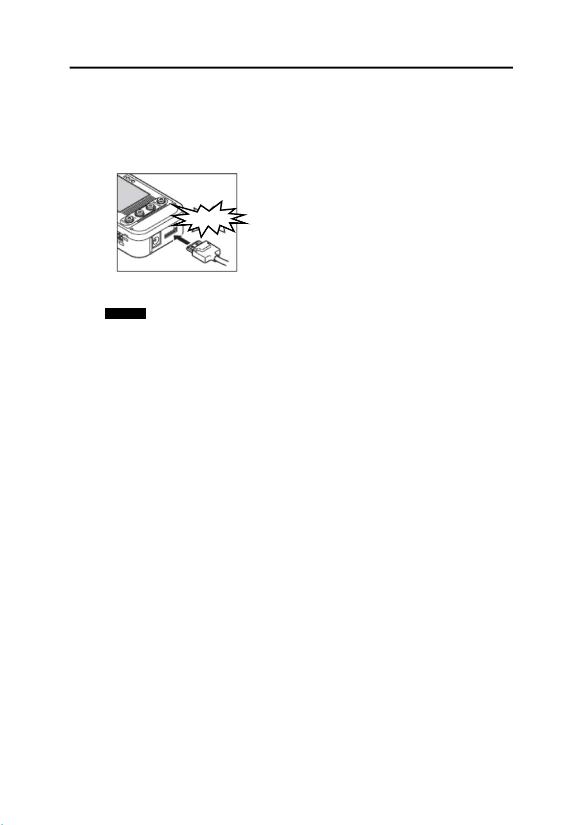
3.6.4 Connecting LAN Cable
Click!
Use LAN cables to connect the Portable Power Monitor units and the PC to the network.
When the LAN cables have been properly connected, the "LAN" indicator turns ON on the
unit display.
3. Check and Preparation
"LAN" Turns ON
3-22
Page 47

3.7 Mounting the Unit
This section describes the procedure to install a Portable Power Monitor unit.
Important
This product is a sensitive device. Take caution not to let it drop when installing.
Use screws to fix the product through the provided mounting screw holes for installation
on the wall or other equipment where vibration or shock may directly affect the unit.
3.7.1 Free-stand Installation
3. Check and Preparation
Important
When placing the product on a desk or other elevated object, place it at a sufficient
distance from the edges or corners of the object to prevent the unit from dropping to be
damaged. Caution must also be taken in laying the power supply cable and the dedicated
CT to avoid their contacting or hitting the unit.
3.7.2 Securing with Mounting Magnets
Two mounting magnets are provided on the rear side of the unit. Use them to securely
mount the unit on the wall or other vertical surface.
Mounting Magnets
Important
Mount the unit on a location where mechanical shock is not applied when mounting it with
magnets.
The cable layout also requires caution not to allow the sensor head and cable apply
pressure to the magnet-mounted unit.
3-23
Page 48

3.7.3 Securing with Mounting Screws
Mounting screw holes are provided on the rear side of the unit, which are attached with
mounting magnets by default. The unit can be screw-mounted through the holes by removing
the magnets. (Refer to the Appendix: Installation Diagram for the screw hole dimensions.)
Flat-head Screws: M3 x 6
Mounting Magnets
Important
The screw holes are 4 mm deep. Do not screw deeper than 4 mm, which may damage
the product.
3.7.4 Screw Hook Mounting
3. Check and Preparation
Two screw hook holes are provided on the rear top of the unit (immediately below the
protrusions on the top), which allow easy mounting of the unit on the wall or other vertical
surface. (Refer to the Appendix: Installation Diagram for the screw hooking hole dimensions.)
Pre-mount the M3 screws on the wall surface and hook the unit on the screws through the
holes. Mount the screws allowing a distance of 2.5 mm or more between the screw head and
the surface.
2.5 mm or more
Enlarged Hook Screw Section View
Important
Firmly hold the unit with your hand to insert or remove the SD card when the unit is
mounted by hooking. Otherwise the unit may drop on the floor and be damaged.
3-24
Page 49

3. Check and Preparation
Branching/Fixing Hook
3.8 Attaching Dedicated CT to Measurement Target
Attach the dedicated CT on the wire to the measurement target.
When using a Clamp-on CT (ZN-CT51A), refer to the instruction sheet of the Clamp-on
C T.
(1) Align the sides of the dedicated CT to the power supply side (K) and load side (L)
correctly. In the figure below, the CT top corresponds to the power supply side and the
bottom to the load side, with the branching/fixing hook facing up.
Power Supply Side (K)
Dedicated CT
Load Side (L)
(2) Spread the CT branching/fixing hook and insert the measurement target wire into the
hook cavity. Let the hook clamp the wire by pressing it until it clicks.
If the number of channels is "1CH", clamp the CT at phase L for a single-phase
two-wire circuit; and clamp at phase R for a three-phase three-wire circuit.
<Single-phase Two-wire> <Three-phase Three-wir e>
Power Supply Side (K) Power Supply Side (K)
Branching/Fixing Hook
Load Side (L) Load Side (L)
If the number of channels is "2CH", clamp CH1 at phase R and CH3 at phase S for a
single-phase three-wire circuit; and clamp CH1 at phase R and CH3 at phase T for a
three-phase three-wire circuit.
3-25
Page 50

3. Check and Preparation
Branching/Fixing Hook
<Single-phase Three-wire> <Three-phase Three-wir e>
Power Supply Side (K) Power Supply Side (K)
Load Side (L) Load Side (L)
If the number of channels is "3CH", clamp CH1 at phase R, CH2 at phase S and CH3 at
phase T.
<Three-phase Four-wir e>
Power Supply Side (K)
Branching/Fixing Hook
Load Side (L)
Important
・Take extra caution against electric shock.
・Do not insert or remove the sensor head to/from the connector when the measurement
target is clamped.
・The Portable Power Monitor unit power must be ON when clamping a measurement
target.
3-26
Page 51

4. Setting the Unit (Unit Operation)
4-1
Display
Name
Description
"RUN" ON
Measurement
(RUN Mode)
Used for power measurement and recording.
"FUN" Blinking
Function Setting
(FUN Mode)
Entered to make measurement and recording
"THR" Blinking
Threshold Setting
(THR Mode)
Entered to make setting on the upper threshold
RUN Mode
FUN Mode
THR Mode
MODE Key
MODE Key
Operation
Operation
Operation
4. Setting the Unit (Unit Operation)
4.1 Setting Procedure and Operation Modes
The following diagram shows the Portable Power Monitor setting procedure flow:
The Portable Power Monitor provides the three operation modes, which can be switched
with the MODE key.
To change the mode from RUN to FUN, press the MODE key twice. At the first press of the
MODE key, “RUN” blinks and at the second, "FUN” blinks and the mode is entered.
Use the △ and ▽ keys to switch among setting and display items in each operation
mode.
△/▽ Key △/▽ Key △/▽ Key
RUN Mode
Twice
FUN Mode
Table: Operation Mode
MODE Key
THR Mode
Execution Mode
Mode
Mode
Note
The mode cannot be changed during data recording in the internal memory in RUN mode
("REC" indicator is ON).
settings.
value for power alarm output.
Page 52

4-2
4.2 Settings (FUN Mode Operation)
Factory
Default
Ranking clear
A press of the REC key
key clears the ranking.
-
Recording
1s (sec.)/2s/5s/10s/20s/
HISPD.
1s
STRIG
Start trigger
OFF/TIME
OFF
STIME
Start time
00:00 to 23:59
00:00
ETRIG
End trigger
OFF/TIME/ELPSD
OFF
ETIME
End time
00:00 to 23:59
00:00
Elapsed time
0.05 (0 min. 5 sec.) to
999.59 (999 min. 59 sec.)
0.05
Measurement
NORM/SLEEP/HISPD
set value is applied.
SLEEP
Recording
mode
CONT/RING
CONT
Integrated
OFF/30min./1h (hrs.)/24h
the MODE key.
OFF
The number of
use
1CH/2CH/3CH
1CH
Measured
The displayed items vary
the channels to use.
3P3
Enter FUN mode to make measurement and recording settings on the Portable Power
Monitor.
4.2.1 Setting Item List
The following list shows the setting items available in FUN mode.
Display Item Display Setting Item Setting Value
4. Setting the Unit (Unit Operation)
CLEAR
CYCLE
TIMER
(ON)
MODE
REC
INTEG
ELPSD
interval
mode
power reset
interval
displays "CLEAR".
Another press of the REC
30s/1min.
This setting item is not
displayed when the
measurement mode is
The unit reset itself and
restarts when the MODE
key is pressed to change
the operation mode after a
"30min.": Integrated power is
reset to zero at 0 and 30 min.
of every hour; "1h": reset at 0
min. of every hour; "24h":
reset at 0:00 every day. The
integrated power up until the
moment of reset is recorded
in the ranking log before it is
cleared to zero.
After the INTEG setting is
changed, the unit resets itself
and restarts, clearing the
ranking, when the operation
mode is changed by pressing
USECH
TYPE
channels to
circuit
depending on the number of
Page 53

4. Setting the Unit (Unit Operation)
4-3
When set to 1CH:
3P4 (Three-phase, four-wire)
Dedicated CT
type
5A/50A/100A/200A
100A
Voltage of
target
1.0 to 9999.9
220
PF Power factor
0.01 to 1.00
0.80
FREQ
Frequency
50Hz/60Hz
50
Restore the
Initialization starts at a
indication appears.
-
Read setting
The unit reads the setting
indication appears.
-
Write setting
The unit saves the setting
SET/REC/STOP key.
-
YEAR
Ye a r
Year setting
Not
MONTH
Month
Month setting
DAY
Day
Day setting
TIME
Hour/Minute
Hour/minute setting
Network
availability
OFF/ON
OFF
192.
20
SUB1 to
255.
0
Rated primary
value
5 to 9999
set to 5A.
Zero-out low
current value
1P2 (Single-phase, two-wire)
/ 3P3 (Three-phase,
three-wir e)
When set to 2CH:
1P3 (Single-phase,
three-wire) / 3P3
(Three-phase, three-wire)
When set to 3CH:
CT
VOLT
INIT
RESTR
BCKUP
measurement
factory default
data from the
SD memory
card.
data to the SD
memory card.
long press of the
SET/REC/STOP key. The
unit restarts when the
operation mode is
changed after the "DONE"
data from a pre-inserted
SD memory card to set
itself, at a long press of
the SET/REC/STOP key.
The unit restarts when the
operation mode is
changed after the "DONE"
data in a pre-inserted SD
memory card, at a long
press of the
ETC
(DISP)
CLOCK
(DISP)
NET
IP
(DISP)
DTAIL
(DISP)
IP1 to IP4
SUB4
SCT5A
LOCUT
function
IP address 0 to 255
Subnet mask 0 to 255
side current
Only effective when CT is
0.1 to 19.9% 0.6%
initialized
b y I N IT.
168.
0.
255.
255.
5A
Page 54

4. Setting the Unit (Unit Operation)
4-4
Measurement
range
Rate/CO2
value setting
JPY/USD/EUR/CNY/
KRW /CO2
REC
startup
RANGE
RATE
CONV
REREC
conversion
Conversion unit
restoration
availability at
NORM/AUTO AUTO
00.000 to 99.999 0
JPY
OFF/ON OFF
Page 55

4-5
4.2.2 Selecting "FUN" Operation Mode
FUN Mode
MODE Key
Key
Key
Key
Operation
Operation
Operation
Press the MODE key to change the operation mode to "FUN". The "FUN" indication on the
right of the display starts blinking.
Note
FUN mode cannot be entered when recording in the internal memory is in progress in RUN
mode ("REC" is ON on the display).
RUN Mode
△/▽
RUN Mode
Twice
FUN Mode
△/▽
4. Setting the Unit (Unit Operation)
MODE Key
THR Mode
MODE Key
△/▽
THR Mode
Page 56

4. Setting the Unit (Unit Operation)
4-6
Whe n TI ME is s et to ON
When STRIG is set to TIME
When ETRIG is set to ELPSD
Whe n IP is set to DISP
Whe n CLOCK is s et to DISP
4.2.3 Selecting Items
Move the selection items using the △ and ▽ keys. To change the set value, select the
item with △ or ▽ key and apply the selection with the SET/REC/STOP key. Press the
MODE key to change the operation mode.
When ETRIG is set to TIME
Whe n ETC is s et to DISP
Whe n DTAIL is s et to DISP
Page 57

4-7
4.2.4 Definition of Items
Measurement Mode (NORM or SLEEP)
Recording
Possible Internal Memory
(1CH)
Possible Internal Memory
(3CH)
1 second
Approx. 1 hr. 45 min.
Approx. 1 hr. 15 min.
2 seconds
Approx. 3 hr. 30 min.
Approx. 2 hr. 30 min.
5 seconds
Approx. 8 hr. 45 min.
Approx. 6 hr. 15 min.
10 seconds
Approx. 17 hr. 30 min.
Approx. 12 hr. 30 min.
20 seconds
Approx. 1 day 11 hr.
Approx. 1 day 1 hr.
30 seconds
Approx. 2 days 4 hr. 30 min.
Approx. 1 day 13 hr. 30 min.
1 minute
Approx. 4 days 9 hr.
Approx. 3 days 3 hr.
Measurement Mode (HISPD)
Frequency
Possible Internal Memory
(1CH)
Possible Internal Memory
(3CH)
50 Hz
Approx. 11 min. 30 sec.
Approx. 8 min. 5 sec.
60 Hz
Approx. 9 min. 35 sec.
Approx. 6 min. 40 sec.
Recording Interval
Battery Life
1 second
Approx. 7 days
2 seconds
Approx. 12 days
5 seconds
Approx. 20 days
(1) Ranking Clear (CLEAR)
Clears the ranking. (The ranking is also cleared when the power is turned OFF.)
Operation:
A press of the REC key displays "CLEAR" at the lower row on the display. If the REC
key is pressed again (when the "CLEAR" indication is displayed), the ranking is cleared.
To cancel the clearing, press the MODE key.
(2) Recording Interval (CYCLE)
Specifies the interval of measured value recording. This setting item is only displayed when
the measurement mode (MODE) is set to "NORM" or "SLEEP".
The range of selection (Options):
1s (second)/ 2s / 5s / 10s / 20s / 30s / 1minute
Initial value: 1s
■Recording Interval and Internal Memory
Possible recording time in the internal memory depends on the recording interval setting as
shown in the table below:
(SD memory cards can be used for continuous recording for a longer time.)
4. Setting the Unit (Unit Operation)
Interval
■Battery Life
Battery life varies depending on the recording interval setting. Refer to the following battery
life table and the battery operation period when setting the recording interval.
Conditions: Two AAA nickel-metal hydride batteries; SLEEP mode; Continue mode;
recording interval: 1s; network function OFF; SD memory card (HMC-SD291) is used;
ambient temperature: 23℃
Recording Time
Recording Time
Recording Time
Recording Time
Page 58

4. Setting the Unit (Unit Operation)
4-8
10 seconds
Approx. 25 days
20 seconds
Approx. 29 days
30 seconds
Approx. 30 days
1 minute
Approx. 32 days
Setting Value
Operation
OFF
The timer function is not used.
key is pressed after the
setting is applied with the SET/REC/STOP key.
ON
The timer function is used.
setting is applied with the SET/REC/STOP key.
Setting Value
Operation
OFF
A long press (for 3 seconds or longer) of the SET/REC/STOP key
setting is applied with the SET/REC/STOP key.
TIME
Recording starts when the specified start time is reached.
setting is applied with the SET/REC/STOP key.
* The table above only shows representative values. The actual battery life depends on the
measurement environment, recording interval, measurement mode as well as the type and
performance of the SD memory card and batteries to use.
(3) Timer Setting (TIMER)
Specifies if the timer function is required.
The range of selection (Options):
OFF / ON
Initial value: OFF
Start trigger and End trigger are also set to OFF.
The MDOE item appears when the ▽
Start trigger and End trigger can be specified.
The STRIG item appears when the ▽ key is pressed after the
Note
・The setting returns to "OFF" when FUN mode is exited, if both Start trigger (STRIG) and
End trigger (ETRIG) are set to "OFF".
(4) Start Trigger (STRIG)
Sets the recording start trigger.
The range of selection (Options):
OFF / TIME
Initial value: OFF
starts recording.
The ETRIG item appears when the ▽ key is pressed after the
The STIME item appears when the ▽ key is pressed after the
Note
・A long press (for 3 seconds or longer) of the SET/REC/STOP key starts recording
overriding the TIME setting.
・If a TIME setting is made, the "REC" indication keeps blinking (indicating that TIME has
been set) until recording starts.
Page 59

4. Setting the Unit (Unit Operation)
4-9
Setting Value
Operation
OFF
A long press (for 3 seconds or longer) of the SET/REC/STOP key
setting is applied with the SET/REC/STOP key.
TIME
Recording stops when the specified end time is reached.
setting is applied with the SET/REC/STOP key.
ELPSD
Recording stops when the specified time has elapsed after the start
setting is applied with the SET/REC/STOP key.
(5) Start Time (STIME)
Specifies the recording start time.
Recording starts at a specified time every day.
Setting range (Numeric input):
00:00 to 23:59
Initial value: 00:00
Note
・STIME cannot be specified when STRIG is set to "OFF".
Important
・Recording continues if recording has been already in progress when the specified start
time is reached.
・Recording does not start if the unit is in error status when the specified start time is
reached.
(6) End Trigger (ETRIG)
Sets the recording end trigger.
The range of selection (Options):
OFF / TIME / ELPSD
Initial value: OFF
stops recording.
The ETRIG item appears when the ▽ key is pressed after the
The STIME item appears when the ▽ key is pressed after the
of recording.
The STIME item appears when the ▽ key is pressed after the
Note
・A long press (for 3 seconds or longer) of the SET/REC/STOP key stops recording
overriding the TIME or ELPSD setting.
Page 60

4. Setting the Unit (Unit Operation)
4-10
(7) End Time (ETIME)
Specifies the recording end time.
Recording stops at a specified time every day.
The range of selection (Numeric input):
00:00 to 23:59
Initial value: 00:00
Note
・ETIME cannot be specified when ETRIG is set to "OFF" or "ELPSD".
・Recording stops when the specified end time is reached overriding a record start command
via key operation or communication.
Important
・Nothing happens if recording has already stopped when the specified end time is reached.
(8) Elapsed Time (ELPSD)
Specifies the elapsed time after recording starts until recording stops.
The range of selection (Numeric input):
0.05 (0 min. 5 sec.) to 999.59 (999 min. 59 sec.)
Initial value: 0.05
Note
・ELPSD cannot be specified when ETRIG is set to "OFF" or "TIME".
・Recording stops when the specified time is elapsed overriding a record stop command via
key operation or communication.
Important
・Nothing happens if recording has already stopped when the specified end time is reached.
Page 61

4. Setting the Unit (Unit Operation)
4-11
Measurement Mode
Operation
NORM
The unit provides normal operation.
SLEEP
Sleep mode
The unit provides energy saving operation. The CPU is in standby
supply.
HISPD
High-speed logging mode
The unit provides recording at the shortest possible interval for
(100ms/50Hz; 83.3ms/60Hz)
Calculate and record an
Current Value
Time Recordi ng Interval
<NORM Mode>
100ms during the specified recording interval
Recordi ng Interval
Recordi ng Interval
Time Time
Current Value Current Value
(9) Measurement Mode (MODE)
Used to select the measurement mode (e.g. SLEEP mode).
The range of selection (Options):
NORM / SLEEP / HISPD
Initial value: SLEEP
mode except when recording at a specified interval.
Operation in this mode is recommended when using battery power
relevant measurement results.
Note
・The unit resets itself and restarts when the MODE key is pressed to change the operation
mode, after the measurement mode has been changed and applied with the
SET/REC/STOP key.
・An alarm output is not available in SLEEP mode.
・Network operation is not available in SLEEP or HISPD mode.
・Measurement operation details vary, as shown below, depending on the measurement
mode setting.
Calculate an effective current value every
and use the values (as measured values) to
obtain the power level.
<SLEEP Mode>
Use the effective current value in the first
100ms of the recording interval as the
measured value of the interval and
obtain the power level.
<HISPD Mode>
effective current value and the
power level at every 100ms.
The effective value is calculated every 83.3ms for measurement at 60 Hz.
Page 62

4. Setting the Unit (Unit Operation)
4-12
Recording Mode
Operation
CONT
Continue mode
continues recording. If an error occurs due to no insertion of an SD
memory card, the unit stops recording and holds the data in the
internal memory.
RING
Ring mode
internal memory becomes full, and continues recording.
Setting Value
Operation
OFF
The unit continuously measures the integrated power without
resetting the value to zero.
30min.
The unit measures the integrated value at the interval of 30 minutes;
1:30…).
1h
The unit measures the integrated value at the interval of one hour; at
0 minutes of every hour (0:00, 1:00, 2:00…).
24h
The unit measures the integrated value at the interval of 24 hours; at
0:00 of every day.
(10) Recording Mode (REC)
Specifies the write operation to the SD memory card during recording.
The range of selection (Options):
CONT / RING
Initial value: CONT
The unit outputs the files in the internal memory to the SD memory
card when the internal memory becomes full during recording, and
The unit overwrites the oldest data in the internal memory when the
Note
・A press of the SET/REC/STOP key (for 3 seconds or less) during recording enables the
unit to output the data accumulated so far in the internal memory to the SD memory card
without stopping recording.
(11) Integrated Power Reset Interval (INTEG)
Specifies the interval for measuring integrated power.
The range of selection (Options):
OFF / 30min./ 1h (hr.) / 24h
Initial value: OFF
at 0 and 30 minutes of every hour (0:00 to 0:30; 0:30 to 1:00; 1:00 to
Note
When you press the MODE key and change the operation mode after changing the set
value, the unit resets the setting and restarts, clearing the ranking.
Important
Only the integrated power is reset on the display, not the integrated power that is output to
a file. Use the integration/summation function of the Station Utility to perform summation
on a PC
Page 63

4. Setting the Unit (Unit Operation)
4-13
(12) The Number of Channels to Use (USECH)
Specifies the number of channels to use. The same number of dedicated CTs must be set.
The range of selection (Options):
1CH / 2CH / 3CH
Initial value: 1CH
(13) Measurement Target Circuit (TYPE)
Select the phase and wire configuration of the circuit to be measured. The items displayed
for selection varies depending on the number of channels to use (USECH).
The range of selection (Options):
・When the number of channels (USECH) is 1CH:
1P2 (Single-phase, two-wire) / 3P3 (Three-phase, three-wire)
・When the number of channels (USECH) is 2CH:
1P3 (Single-phase, three-wire) / 3P3 (Three-phase, three-wire )
・When the number of channels (USECH) is 3CH:
3P4 (Three-phase, four-wire)
Initial value: 3P3
(14) Dedicated CT Type (CT)
Used to select the type of the dedicated CT to use. Make sure that the type of the CT to use
is specified.
The range of selection (Options):
5A / 50A / 100A / 200A
Initial value: 100A
(15) Voltage of Measurement Target (VOLT)
Specifies the effective voltage in the circuit to be measured. Make sure that a correct value
is specified since it is used to obtain the current value in the circuit.
The range of selection (Numeric input):
1.0 to 9999.9
Initial value: 220
Page 64

4. Setting the Unit (Unit Operation)
4-14
(16) Power Factor (PF)
Specifies the power factor of the circuit to be measured. The power factor refers to the ratio
of the real power to the apparent power in the circuit. The power factor varies depending on
the measurement target; however, it generally ranges from approx. 0.6 to 1.0. Since it is used
by the unit to convert a current value into a power value, it must be adjusted specifically on
individual measurement targets.
The range of selection (Numeric input):
0.01 to 1.00
Initial value: 0.8
(17) Frequency (FREQ)
Used to select the power frequency at which the measurement target operates, according to
the power frequency used in your region or country. The unit uses the frequency to measure
current values. The correct frequency must be specified for measurement accuracy.
The range of selection (Options):
50Hz / 60Hz
Initial value: 50Hz
(18) Initialization (INIT)
The unit initializes the setting values and restores the factory defaults (except for year,
month, day, hour and minute settings).
Operation:
Initialization starts at a long press of the SET/REC/STOP key and is completed when
“DONE” is displayed.
The unit resets itself and restarts when the MODE key is pressed to change the
operation mode.
Page 65

4. Setting the Unit (Unit Operation)
4-15
Setting Value
Operation
OFF
The unit does not display the items for setting data read/write, time
setting is applied with the SET/REC/STOP key.
DISP
The unit displays the items for setting data read/write, time setting,
key is pressed after the
setting is applied with the SET/REC/STOP key.
(19) Others (ETC)
Specifies if the unit displays the items for setting file read/write, time setting, and network
setting.
Setting range:
OFF / DISP
Initial value: OFF
setting, network setting, DTA IL , rate/CO2 conversion value setting
and conversion unit setting.
The RNKCL item returns when the ▽ key is pressed after the
network setting, DTA I L , rate/CO2 conversion value setting and
conversion unit setting.
The RESTR item is displayed when the ▽
Note
The ETC setting returns to "OFF" when the unit is reset.
(20) Reading Setting Data (RESTR)
Restores the unit settings by using the SD memory card with the setting data saved as a
backup using the BCKUP setting (described later).
Operation:
Insert the SD card containing the setting data, and hold the SET/REC/STOP key.
Reading is completed when “DONE” is displayed.
The unit resets itself and restarts when the MODE key is pressed to change the
operation mode.
Note
・Only one setting data item (the setting data for only one unit) can be stored in a single SD
card as a backup. The setting data backed up in one Portable Power Monitor can be
restored on other Portable Power Monitor unit.
・Setting data reading is not possible when ETC is set to "OFF".
Page 66

4. Setting the Unit (Unit Operation)
4-16
Setting Value
Operation
OFF
Time setting is not available.
setting is applied with the SET/REC/STOP key.
DISP
Time setting is available.
setting is applied with the SET/REC/STOP key.
(21) Writing the Setting Data (BCKUP)
Saves the unit setting data in an SD memory card as a backup.
Operation:
Insert an SD memory card and hold the SET/REC/STOP key.
Saving is complete when “DONE” is displayed.
Important
Only one setting data item (the setting data for only one unit) can be stored in a single SD
card as a backup. If an SD card containing an alread y-saved setting data backup is used, the
setting data in the card is overwritten. The same applies to a backup performed on other
Portable Power Monitor: the data is overwritten.
Note
・The setting data is written into the SYSTEM folder in the SD card.
・Setting data writing is not possible when ETC is set to "OFF".
(22) Time Setting (CLOCK)
Specifies if the time setting is required.
The range of selection (Options):
OFF / DISP
Initial value: OFF
The D TA IL item is displayed when the ▽ key is pressed after the
The YEAR item is displayed when the ▽ key is pressed after the
Note
・The CLOCK setting is not possible when ETC is set to "OFF".
・The CLOCK setting returns to "OFF" when the unit is reset.
Page 67

4. Setting the Unit (Unit Operation)
4-17
Setting Value
Operation
OFF
IP address settings are not available.
setting is applied with the SET/REC/STOP key.
DISP
IP address settings are available.
setting is applied with the SET/REC/STOP key.
(23) YEAR/MONTH/DAY/TIME Setting
Specifies the year/month/day/time values.
Setting range (Numeric input):
YEAR: 2000 to 2099
MONTH:1 to 12
DAY: 1 to 31
TIME: 00:00 to 23:59
Note
The year/month/day/time settings are not possible when ETC is set to "OFF" and CLOCK
is also set to "OFF".
(24) Network Setting (NET)
Specifies if the network functions are required. However, this setting is only effective when
the measurement mode (MODE) is set to "NORM".
The range of selection (Options):
OFF/ON
Initial value: OFF
(25) Setting IP Address (IP)
Specifies if the IP address setting is required.
The range of selection (Options):
OFF / DISP
Initial value: OFF
The D TA IL item is displayed when the ▽ key is pressed after the
The IP 1 item is displayed when the ▽ key is pressed after the
Note
・The IP setting is not possible when ETC is set to "OFF".
・The IP setting returns to "OFF" when the unit is reset.
Page 68

4. Setting the Unit (Unit Operation)
4-18
Setting Value
Operation
OFF
A rated primary side current value, zero-out low current value and
setting is applied with the SET/REC/STOP key.
DISP
A rated primary side current value, zero-out low current value and
setting is applied with the SET/REC/STOP key.
(26) IP Address and Subnet Mask (IP 1 to IP 4, SUB 1 to SUB 4)
Specifies the 4 segments of the IP address (IP 1 to IP 4) and the 4 segments of the subnet
mask (SUB 1 to SUB 4).
Setting range (Numeric input):
IP 1, IP 2, IP 3, IP 4: 0 to 255
SUB 1, SUB 2, SUB 3, SUB 4: 0 to 255
Initial value: IP 1.IP 2.IP 3.IP 4 = 192.168.0.20
SUB 1.SUB 2.SUB 3.SUB 4 = 255.255.255.0
Note
・The unit resets itself and restarts when the MODE key is pressed to change the operation
mode, after the IP address and subnet mask values have been changed and applied with
the SET/REC/STOP key.
・The IP address and subnet mask settings are not possible when ETC is set to "OFF" and
IP is also set to "OFF".
(27) DTAIL
Sets if a rated primary side current value, zero-out low current value and measurement
range are specified.
The range of selection (Options):
OFF / DISP
Initial value: OFF
measurement range cannot be specified.
The RATE item is displayed when the ▽ key is pressed after the
measurement range can be specified.
The SCT5A item is displayed when the ▽ key is pressed after the
Note
・The DTAIL setting is not possible when ETC is set to "OFF".
・The DTAIL setting returns to "OFF" when the unit is reset.
(28) Rated Primary Side Current Value (SCT5A)
Specifies the rated primary side current value. However, this setting is only effective when
the dedicated CT type (CT) is set to "5A".
The range of selection (Numeric input):
5 to 9999
Initial value: 5
Page 69

4. Setting the Unit (Unit Operation)
4-19
Setting Value
Operation
NORM
The measurement range is fixed.
AUTO
The measurement range is automatically switched with
approximately 5% or less of the CT rated current.
CT rating
Approx. more
than 5%
Approx. 5% or
less
5A
0.1A
0.007A
50A
1.0A
0.063A
100A
2.0A
0.125A
200A
4.0A
0.250A
Note
The rated primary side current value cannot be specified when ETC is set to "OFF" and
DTAIL is also set to "OFF".
(29) Zero-out Low Current Value (LOCUT)
Determines low current values to be zeroed out by specifying the threshold value in a
percentage to the dedicated CT type (CT) current value. The current values equal to or lower
than the specified value are deemed noise and therefore ignored. For example, if 0.6% (initial
value) is specified and the CT value is 100A, the values equal to or lower than 0.6A (i.e. 0.6%
of 100A) are all eliminated as noise.
The range of selection (Numeric input):
0.1 to 19.9%
Initial value: 0.6%
Note
The LOCUT setting is not possible when ETC is set to "OFF" and DTAIL is also set to
"OFF".
(30) Measurement Range (RANGE)
Specifies the measurement range.
The range of selection (Options):
NORM / AUTO
Initial value: AUTO
Note
The table below shows the resolutions (reference values) under AUTO setting.
* The reference value indicates a typical value, not a guaranteed value.
The measurement range cannot be specified when ETC is OFF and DTAIL is OFF.
Page 70

4. Setting the Unit (Unit Operation)
4-20
Setting Value
Operation
OFF
The unit does not automatically start recording at the next startup
after a power failure during recording.
ON
The unit automatically writes data to a memory card and starts
recording at the next startup after a power failure during recording.
(31) Rate/CO2 Conversion Value Setting (RATE)
Specifies the electricity rate or CO2 emission level per 1kWh.
The range of selection (Numeric input):
00.000 to 99.999
Initial value: 0.000
Note
The rate/CO2 conversion value setting is not possible when ETC is set to "OFF".
(32) Conversion Unit Setting (CONV)
Specifies the unit for the rate/CO2 conversion setting (RATE).
The range of selection (Options):
JPY (Japanese yen) / USD (US dollar) / EUR (Euro) / CNY (Chinese yuan) / KRW
(Korean won) /
(CO2 emission level per 1kWh)
CO
2
Initial value: JPY
Note
The conversion unit cannot be specified when ETC is set to "OFF".
(33) Power Startup REC Restoration (REREC)
Specifies if the REC restoration function is used in the event of power startup.
The range of selection (Options):
OFF / ON
Initial value: OFF
Note
The power startup REC restoration setting is not possible when ETC is set to "OFF".
Important
An error occurs if an SD memory card is not inserted at the startup immediately after a
power failure when the REC restoration is set to "ON". The unit fails in writing data to the
memory card and does not start recording. To solve this situation, cancel the error state and
start recording via key operation.
Page 71

4. Setting the Unit (Unit Operation)
4-21
Display
(Upper/Lower)
Operation
Press the MODE key repeatedly until "FUN" starts blinking. Press
starts blinking.
SET/REC/STOP Key↓
Display
(Upper/Lower)
Operation
The value options are displayed in sequence by pressing the △ or
▽ or △ Key↓
Display
(Upper/Lower)
Operation
CYCLE
Blinking
Press the △ or ▽ key to display the desired value, and press the
The value is applied and the blinking stops.
SET/REC/STOP Key↓
Display
(Upper/Lower)
Operation
4.2.5 Changing the Set Value
The value setting depends on the type of items, which are classified into option selection
type and numeric input type.
(1) Changing Option Type Item Values (Example: CYCLE)
Press the MODE key several times to enter FUN mode, and press the ▽ or △ key to
display CYCLE.
CYCLE
10 s
CYCLE
10 s
↑Blinking
30 s
↑
CYCLE
30 s
Use the △ or ▽ key again to display other setting item and MODE key to change the
operation mode.
the ▽ or △ key to display CYCLE at the upper row of the display.
Press the SET/REC/STOP key, then, the value at the lower row
▽ ke y.
To cancel the setting attempt, press the MODE key.
SET/REC/STOP key.
Page 72

4. Setting the Unit (Unit Operation)
4-22
Display
(Upper/Lower)
Operation
Press the MODE key repeatedly until "FUN" starts blinking.
key to display YEAR. To display YEAR, ETC
and TIME must be set to DISP.
Display
(Upper/Lower)
Operation
Press the SET/REC/STOP key, then, the last digit number at the
SET/REC/STOP Key↓
Display
(Upper/Lower)
Operation
The value increases or decreases at a press of the △ or ▽ ke y.
To cancel the setting attempt, press the MODE key.
Display
(Upper/Lower)
Operation
YEAR
↑Blinking
Press the △ or ▽ key to display the desired value, and press the
The value is applied and the blinking stops.
SET/REC/STOP Key↓
Display
(Upper/Lower)
Operation
(2) Changing Numeric Input Type Item Value (Example: YEAR)
Press the MODE key several times to enter FUN mode, and press the ▽ or △ key to
display YEAR.
To display YEAR, ETC and TIME must have been set to DISP beforehand.
CYCLE
10s
("FUN" Blinking)
▽ or △ Key↓
YEAR
2010
YEAR
2010
↑Blinking
▽ or △ Key↓
2011
"CYCLE" is displayed at the upper row.
Press the ▽ or △
lower ro w starts blinking.
The amount of increase/decrease becomes larger by holding △ or
▽ ke y.
SET/REC/STOP key.
YEAR
2011
Use the △ or ▽ key again to display other setting item and MODE key to change the
operation mode.
Page 73

4. Setting the Unit (Unit Operation)
4-23
Display
Item
Factory
Default
of kWh or higher
Specifies the integrated
output (kWh or higher).
of less than kWh
Specifies the integrated
power upper limit
output (less than kWh).
4.3 Settings (THR Mode Operation)
THR mode must be entered for setting the threshold for Portable Power Monitor alarm
output.
Set the upper limit of the integrated power consumption for the threshold value.
If the measured value exceeds the set upper limit value during RUN operation, the station's
alarm output terminal turns ON and the "ALM" indication on the display turns ON.
Note
・An alarm is not output when the measurement mode (MODE) is set to "SLEEP".
・Alarm monitoring cannot be stopped.
However, it can be avoided by setting the threshold value to "0". The factory default is set
to the value (0) in which alarm monitoring is not performed.
4.3.1 Setting Item List
The table below shows the THR mode setting item list.
Display Setting Item Function/Operation
INT H
INT H
Upper limit threshold
integrated power
Upper limit threshold
integrated power
power upper limit
threshold value for alarm
threshold value for alarm
0 kWh
0 Wh
Page 74

4. Setting the Unit (Unit Operation)
4-24
RUN Mode
FUN Mode
THR Mode
MODE Key
Operation
INT H
0 kWh
INT H
0 Wh
4.3.2 Selecting "THR" Operation Mode
Press the MODE key to change the operation mode to "THR". "THR" at the lower right of
the display starts blinking.
△/▽ Key △/▽ Key △/▽ Key
RUN Mode
Operation
Twice
FUN Mode
Operation
MODE Key
MODE Key
THR Mode
4.3.3 Selecting Items
Move the selection items using the △ and ▽ keys. To change the set value, select the
item with △ or ▽ key and apply the selection with the SET/REC/STOP key. Press the
MODE key to change the operation mode.
Page 75

4. Setting the Unit (Unit Operation)
4-25
4.3.4 Definition of Items
(1) Upper Limit Threshold of kWh or Higher Integrated Power (INT H)
Specifies the integrated power consumption upper limit threshold for an alarm output.
The "ALM" indication and alarm output turn ON, when the measured integrated power
exceeds the set value.
Setting range (Numeric input):
0 Wh to 99999 kWh (Threshold setting becomes "OFF" if "0" is specified)
Initial value:
0 kWh
(2) Upper Limit Threshold of Less than kWh Integrated Power (INT H)
Specifies the integrated power consumption upper limit threshold for an alarm output.
The "ALM" indication and alarm output turn ON, when the measured integrated power
exceeds the set value.
Setting range (Numeric input):
0 Wh to 999 Wh (Threshold setting becomes "OFF" if "0" is specified)
Initial value:
0 Wh
4.3.5 Changing the Set Value
Follow the same procedure as in FUN mode.
Refer to: 4.2.5 Changing the Set Value
4.4 Copying Setting Data for Multiple Monitor Units
The settings on multiple Portable Power Monitor units can be unified by using the same
setting data saved in an SD memory card. This is convenient especially when controlling
multiple monitor units using the same settings. Make necessary settings only on one unit
(through unit operation), save it in an SD memory card and then, restore it in other units. This
can greatly save the entire setting procedures, thus, minimizing setting errors.
Refer to: 4.2.4 (14) Writing the Setting Data (BCKUP), 4.2.4 (13) Reading Setting Data
(RESTR)
Page 76

5. Measurement and Recording (Unit Operation)
5-1
RUN Mode
MODE Key
MODE Key
Key
Key
Key
Operation
Operation
Operation
5. Measurement and Recording (Unit Operation)
5.1 Overview
Measured values can be recorded in two ways: recording in Portable Power Monitor units or
in the PC via network. This chapter explains recording in Portable Power Monitor units.
5.2 Selecting Operation Mode
RUN mode must be entered for power measurement.
Press the MODE key to change the operation mode to "RUN". "RUN" at the bottom right of
the display turns ON.
Note
A shift to other mode is prohibited during recording.
△/▽
RUN Mode
Twice
FUN Mode THR Mode
△/▽
FUN Mode
MODE Key
△/▽
THR Mode
Page 77

5. Measurement and Recording (Unit Operation)
5-2
Upper: No display.
Lower: Displays the momentary power (kW).
Upper: "CHx" is displayed. "x" changes according to the number of used channels
Lower: Displays the momentary power of the individual channel.
Upper: Shows the elapsed time from the measurement start. Displayed in "min., sec."
first hour. After one hour has elapsed, it is displayed in "min.,
When end trigger (ETRIG) is set, the remaining time up to recording stop is
power reset interval (INTEG) in FUN mode.
Upper: No display.
setting.
CHx
Individual CH Momentary Current
Elapsed Time (min., sec.)
Integrated Power
Momentary Power
Ave. Momentary Power
Max. Momentary Power
Max. Momentary Power
Elapsed Time (day, hr.)
Integrated Power
5.3 Screen Transition in RUN Mode
Pressing the △ or ▽ key in RUN mode switches the display as shown below. Pressing
the MODE key changes the operation mode.
(USECH setting); e.g. "CH1", "CH2", or "CH3".
units during the
sec." and "day, hr." alternately.
displayed.
Lower: Displays the integrated power.
Note
The integrated value can be periodically reset to "0" by specifying the integrated
Lower: Sequentially displays the average (AVE), maximum (MAX) and minimum (MIN)
momentary power values. The values are reset together with the integrated
power value at the time specified by the integrated power reset interval (INTEG)
Page 78

5. Measurement and Recording (Unit Operation)
5-3
Upper: Displays the rate/CO2 conversion value.
Lower: Shows the unit of the rate/CO2 conversion value.
The unit shows the integrated power ranking from the highest to lowest value for
Lower: Displays the integrated power of the rank displayed at the upper row.
Continuously displays the ranking information.
pertaining to the ranking shown at the upper row.
Continuously displays the ranking information.
integrated power values.
eding ranks up to the 9th and their information are
Upper: Displays the integrated power from the measurement start.
Lower: Displays the upper limit threshold value.
Upper: Displays the integral power.
Lower: Displays the threshold rate (Integrated Power ÷Threshold).
Rate/CO2 Conversion Value
Unit
Ranking
Start Date
Ranking
St art Ti m e
Integrated Power
Threshold Value
AVE
Ave. Momentary Power
MAX
Max. Momentary Power
MIN
Min. Momentary Power
・・・
Ranking
Integrated Power
Integrated Power
Threshold Rate
individual intervals specified by the INTEG setting.
The display starts from the 1st rank.
Upper: Displays the ranking.
Ranking Display
Upper: Displays the ranking.
Lower: Alternately displays the integrated power measurement start date and start time
Upper: Displays the "AVE", "MAX" and "MIN" indications repeatedly.
Lower: Repeatedly shows the average (AVE), maximum (MAX) and minimum (MIN)
Similarly, the succe
sequentially displayed.
Page 79

5. Measurement and Recording (Unit Operation)
5-4
Upper: Displays the number of recorded data items
Lower: Displays the current time.
Returns to the first display.
Current Time
Number of Recorded Data Items
Note
・The "REC" indication turns ON during data recording.
・"ALM" turns ON when the measured value exceeds the upper limit threshold value or the
alarm output is ON. To cancel the retained alarm, hold the MODE key.
Page 80

5. Measurement and Recording (Unit Operation)
5-5
5.4 Starting/Stopping Recording
5.4.1 Starting Recording
The unit starts recording power level when the SET/REC/STOP key is held (long press for
at least 3 seconds) in RUN mode or when the specified start time is reached. The "REC"
indication turns ON when recording starts.
The measured data is recorded and accumulated in the internal memory, and is output in a
CSV file to the SD memory card when the SET/REC/STOP key is pressed.
Important
・If recording starts with recorded data remaining in the internal memory, the remaining
recorded data is lost. To save the data, press the SET/REC/STOP key for less than 3
seconds to output the data to the SD card before recording. Recorded data remaining in
the internal memory is the result of the unit restarting after a power failure or a press of
the reset switch in midst of recording. This situation does not happen if recording is
correctly stopped.
To check for remaining data, press the ▽ or △ key in RUN mode to locate the display
in which the current time is shown at the lower row. Check its upper row, and if its value is
"0", then there is no data remaining in the internal memory.
・The unit cannot start recording while an error message is shown in the display. Remove
the error cause, and cancel the error status by holding the MODE key (3 seconds or
longer). Then, start recording.
Note
・The Power Startup REC Restoration (REREC) function automatically resumes recording (if
it is set to "ON") when the unit restarts after it was accidentally turned OFF during
recording.
・An SD memory card must be placed in the unit when the SET/REC/STOP key is pressed
for data output during recording or when recording is stopped. It is not necessarily the
case at the point when the unit starts recording.
・Disable the write protection of an SD memory card. If it is enabled, an error occurs when
the unit attempts to write data to the card (when the internal memory becomes full) and
recording stops.
・A shift to other mode is prohibited during recording.
5.4.2 Stopping Recording
The unit stops recording and outputs files to the SD memory card when the SET/REC/STOP
key is held (long press for at least 3 seconds) during recording ("REC" is ON) or when the
specified end time is reached. The "REC" indication turns OFF when recording stops.
Important
A write-enabled SD memory card must be inserted in the slot when stopping recording. If
a data output attempt fails, recording stops with the recorded data in the internal memory
retained and the error message is displayed. Hold the MODE key (3 seconds or longer) to
cancel the error status. Insert an SD memory card and output the recorded data file to the
card by pressing SET/REC/STOP key. Do not start recording before the data in the
Page 81

5. Measurement and Recording (Unit Operation)
5-6
internal memory is written to the SD memory card. The data is discarded once the unit
starts recording.
5.5 SD Outputting File to SD Memory Card
Recorded data can be output to SD memory card files when any of the following cases
happen.
(a) The SET/REC/STOP is pressed (for less than 3 seconds) during recording. Recording in
the internal memory continues.
(b) The SET/REC/STOP key is held (for 3 seconds or longer) during recording. Recording in
the internal memory stops.
Refer to: 5.4.2 Stopping Recording
(c) The internal memory becomes full during recording. Recording in the internal memory
continues. (The recording mode must have been set to "Continue mode".)
Refer to :4.2.4 (4) Recording Mode (REC)
(d) The SET/REC/STOP key is pressed (for less than 3 seconds in RUN mode) during
non-recording process, when recorded data remains in the internal memory. This refers
to the case that the unit restarts after it is reset during recording due to a power failure or
other reason.
(e) The Power Startup REC Restoration function (REREC) is set to ON, and the unit
restarted after a power failure during recording. Recording will start automatically after
completion of file output. If a file output failed, an error occurs and recording will not
start.
Reference: 4.2.4 (33) Power Startup REC Restoration Function
5.6 Cancelling Retained Alarm
"ALM" turns ON when the integrated power value exceeds the upper limit threshold or the
alarm output is ON.
To cancel the retained alarm, hold the MODE key (for 3 seconds or longer).
A generated alarm will not be automatically cancelled even if the integrated power is reset
and the value falls short of the threshold by the integrated power reset setting (INTEG).
5.7 Display Turning OFF
The display may turn OFF during recording in RUN mode if the unit has not been operated
for 10 seconds. This suggests that the unit has entered SLEEP mode. Despite the screen
being turned OFF, recording still continues as long as the unit is in recording process.
To activate the display again, press any key. A key pressed when the display is turned OFF
only triggers the display to turn ON, regardless of its specific function assigned. To execute
Page 82

5. Measurement and Recording (Unit Operation)
5-7
the function assigned to that key, press it again when the display has recovered from
SLEEP mode.
Refer to: 4.2.4 (3) Measurement Mode (MODE)
Page 83

6-1
6. Ratings and Performance
Item
Description
Connectable Sensor
ZN-CTS□1-□A, ZN-CTM□1-□A
Display
7-seg. 5-digit 2-step LCD display, auxiliary information indicator
displays
Recording Interval
1 s, 2 s, 5 s, 10 s, 20 s, 30 s, 1 min.
*1
Operation Function*2
Momentary power, Integrated power consumption
Measurement
Operation Mode
Normal mode, Sleep mode*3, High-speed logging mode
Recording Mode
Continue mode*4, Ring mode*5
External Output
Alarm output (Photocoupler output) *6
Memory Capacity
(Internal)
Internal memory: approx. 6500 data items (The number of CHs is 1)
Memory Capacity
(External)
SD card with SDHC compatibility*7 (Save measured values and
converted values; save and read setting values)
Power Supply
DC input: 24 VDC±10%
Batteries: Two AAA batteries*8
Current Consumption
Max. 80 mA (AC adapter used)
Battery Life*9
Approx. 1 week*10
Operating
Battery Supply: -10℃ to 60℃ (no condensation or icing)
AC Adapter: 0℃ to 40℃ (no condensation or icing)
Operating Humidity
20 to 85%RH (no condensation or icing)
Storage
Humidity/Temperature
-15℃ to +60℃, 20 to 85%RH (no condensation or icing)
Insulation Resistance
20 MΩ (with DC500V Megger)
Withstand Voltage
1000 VAC, 50/60 Hz, 1 min.: Between the case and I/O terminal
Vibration Resistance
With mounting screws: 10 to 150 Hz, 0.7 mm double amplitude,
0.3 mm double amplitude,
acceleration: 20 m/s2 for each in X, Y and Z directions for 50 min.
Shock Resistance
150 m/s2 in 6 directions (+/-X, +/-Y, and +/-Z directions), 3 times
each*11
Material
ABS
Degree of Protection
IP30
Mounting
Magnet mounting, screw mounting, hook, free standing
Dimensions (WDH)
117.2 × 24.6 × 56.8 mm (Excluding protrusions)
Weight (in Package)
Approx. 500 g
Accessories
Instruction Sheet, Startup Guide, Mounting Magnets*12, Alarm Output
Connector*13, AC Adapter, DC cable, Ferrite core
AC adapter: 100 to 240 VAC/50 to 60 Hz
6. Ratings and Performance
Temperature
acceleration: 50 m/s2 for each in X, Y and Z directions for 80 min.
With mounting magnets: 10 to 55 Hz,
*1: In high-speed logging mode, data is recorded in 83 ms at 60 Hz and in 100 ms at 50 Hz.
*2: Momentary power and integrated power values are converted from the measured current.
Correctly specify the number of used channels, applicable measurement target circuit, CT
type, frequency, voltage and power factor.
*3: The display turns OFF after 10 seconds of no user operation and recovers by a key
operation when SLEEP mode is specified. LAN cannot be used when sleep mode is
specified.
*4: Automatically writes the data to the SD memory card when the internal memory reaches its
capacity and continues recording until the SD card memory capacity reaches its limit. The
unit stops operation if there is no SD memory card inserted when the internal memory
reaches its capacity. (Recording can be resumed after inserting an SD memory card and
Page 84

6. Ratings and Performance
6-2
outputting the data to it at a press of button.)
*5: Continues the recording of the latest measured values until the internal memory reaches its
capacity. (If the internal memory capacity exceeds the capacity, data is overwritten from the
oldest one in the memory.)
*6: Output when the integrated power upper limit specified in THR mode is exceeded. An alarm
output is not available in SLEEP mode.
*7: An OMRON HMC-SD291 SD Memory Card or an SDHC Class 4 or higher memory card is
recommended.
*8: Nickel-metal hydride cells or alkaline dry cells can be used. Manganese battery cells cannot
be used.
*9: Battery life varies depending on the measurement environment, recording interval, operation
mode as well as the battery type and performance.
*10: Conditions: Two AAA nickel-metal hydride cells; Sleep mode; Continue mode; Recording
interval: 1 s; SD mem ory card: HMC-SD291; and Operation temperature: 23℃; and Automatic
range selection off.
*11: The installation place must be free from physical shock when using mounting magnets.
*12: Already installed on the product by factory default.
*13: OMRON's XW4B-02B1-H1 connector.
Page 85

Appendix
Display
Upper/Lower
Measured data
Failed to write recorded data to the SD memory card due
error display.
An SD memory card is not inserted. Insert a
error display.
Unable to
access the SD
The SD memory card cannot be accessed due to the
error display.
SD memory
The SD memory card is write-protected. Replace it with
error display.
SD memory
Failed to recognize the SD memory card. Insert a normal
error display.
Invalid setting
The setting data in the SD memory card is invalid e.g. an
error display.
Setting file
Failed to write setting files to the SD memory card due to
error display.
Setting file
There is no setting files contained in the SD memory
error display.
There may be a failure on the hardware. Please contact
displayed error code is required for identifying the
problem.
Error Display List
Appendix
Description Troubleshooting
DATA
E11 00
NO SD
E3000
BATLO
E3001
SDLCK
E3002
SD ER
E3003
RESTR
E5000
writing failure
No SD memory
card inserted
memory card
Write-protected
card
card recognition
error
file data
to no free space or the card being removed during
writing. Insert a write-enabled SD card.
Hold the MODE key for 3 seconds or more to cancel the
write-enabled SD card.
Hold the MODE key for 3 seconds or more to cancel the
battery voltage drop. Replace the batteries or connect to
the AC adapter.
Hold the MODE key for 3 seconds or more to cancel the
a write-enabled one.
Hold the MODE key for 3 seconds or more to cancel the
SD memory card.
Hold the MODE key for 3 seconds or more to cancel the
invalid model type or setting values.
Hold the MODE key for 3 seconds or more to cancel the
BCKUP
E5001
RESTR
E5002
HARD
E****
writing failure
reading failure
Hardware error
no free space or the card being write-protected. Insert a
write-enabled SD card.
Hold the MODE key for 3 seconds or more to cancel the
card. Replace it with an SD memory card with setting
files.
Hold the MODE key for 3 seconds or more to cancel the
the distributor or OMRON representative office. The
Appendix-1
Page 86

Character Display List
Display
Strin g
Display
Strin g
Display
Strin g
Appendix
Main Messages
Appendix-2
Page 87

SD Memory Card Folder Structure
File/Folder Name
Description
For system use.
Do not modify the file names or the internal files.
For system use.
Do not modify the file names or the internal files.
Folder for storing recorded data.
the Portable Power Monitor unit numbers.
Sub folders for storing recorded data.
The recorded data file is written at 12:24:56.
_FARM
SYSTEM
[Serial Number]
Recorded Data
[
]
[ Ye a r -Month-Day]
(20000101.001 to
20991231.999)
Recorded
Dat
(CSV File)
/
Root Folder
System Folder
System Folder
Folder
年月日
Appendix
a
_FARM
SYSTEM
[Serial Number]
[ Ye a r -Month-Day]
The folders are named with the serial numbers corresponding to
Folder Name Structure:
"Recorded time and date (YYYYMMDD format) + . + Serial No."
Example: 20111001.001
The folder is written on October 1, 2011.
Recorded data file is created in the CSV format.
File Name Structure:
"Hour-Minute-Second + Serial No.".CSV
Example: 12345601.CSV
Appendix-3
Page 88

Calibration
Portable Power Monitor units do not required calibration.
Appendix
Appendix-4
Page 89

Installation Diagram
Mounting Screw
Screw Hook Installation Dimension
Appendix
Screw Hook Holes
Installation Dimension
Mounting Screw Holes: 2-M3; Depth: 4 mm
(Unit: mm)
Appendix-5
Page 90

Revision History
The specifications of this product are subject to changes without prior notice due to the addition of new
functions or modification for improvement. These changes will be reflected in relevant manuals
whenever such changes are made.
The revised manual contains the revision history with the manual revision codes and the revision
descriptions.
Manual Revision Code
The manual revision code is provided at the lower right corner of the manual.
Revision History
R ev. □
Revision Code
Revision
Code
Rev. A October 2011 First edition
Rev. B November 2012 Correspondence of display unit change
Rev. C December 2016 Revised due to change of PC software distribution method.
Date Description
Page 91

ASC -DE-111020-8C
 Loading...