

Page 1
Smart Sensor
Vision Sensor with built-in LCD monitor
ZFX-C20
User's Manual
Cat. No. Z264-E1-02
Page 2
Introduction
Thank you for purchasing the ZFX-C.
This manual provides information regarding functions, performance and operating methods that
are required for using the ZFX-C.
When using the ZFX-C, be sure to observe the following:
• The ZFX-C must be operated by personnel knowledgeable in electrical engineering.
• To ensure correct use, please read this manual thoroughly to deepen your understanding of the
product.
• Please keep this manual in a safe place so that it can be referred to whenever necessary.
Manuals Provided with this Product
Smart Sensor
Vision Sensor with built-in LCD monitor
ZFX-C20
User's Manual
Smart Sensor
Vision Sensor with built-in LCD monitor
ZFX-C20
Serial Communication
Command Reference
Cat. No. Z264-E1-01
Cat. No. Z265-E1-01
User's Manual (this document)
This manual describes basic operations, such as
installation and connections, and information on settings
and specifications to ensure safe and correct use of this
product.
Serial Communication Command
Reference
This manual provides reference information for when this
product performs communications with an external
device, such as a PC or a programmable controller, via
the serial interface.
Page 3
APPLICA TION CONSIDERA TIO NS
(Please Read)
1
User's Manual
BEFORE USE
BASIC OPERATIONS
SETTING THE MEASUREMENT
CONDITIONS
FUNCTIONS USED DURING OPERATION
ADDITIONAL FUNCTIONS
PARALLEL INTERFACE
1
2
3
4
5
6
Smart Sensor
Vision Sensor with built-in LCD monitor
ZFX-C20
APPENDICES
7
Page 4

READ AND UNDERSTAND THIS DOCUMENT
Please read and understand this document before using the products. Please consult your OMRON
representative if you have any questions or comments.
WARRANTY
OMRON’s exclusive w arranty is that the products are f ree from defects in materials a nd workmanship for a
period of one year (or othe r pe ri od if specified) from date of sale by OMRO N .
OMRON MAKES NO WARRANTY OR REPRESENTATION, EXPRESS OR IMPLIED, REGARDING NONINFRINGEMENT, MERCHANTABILITY, OR FITNESS FOR PARTICULAR PURPOSE OF THE PRODU CTS.
ANY BUYER OR USER ACKNOWLEDGES THA T THE BUYER OR USER ALONE HAS DETERMINED THAT
THE PRODUCTS WILL SUITABLY MEET THE REQUIREMENTS OF THEIR INTENDED USE. OMRON
DISCLAIMS ALL OTHER WARRANTIES, EXPRESS OR IMPLIED.
LIMITATIONS OF LIABILITY
OMRON SHALL NOT BE RESPONSIBLE FOR SPECIAL, INDIRECT, OR CONSEQUENTIAL DAMAGES,
LOSS OF PROFITS OR COMMERCIAL LOSS IN ANY WAY CONNECTED WITH THE PRODUCTS,
WHETHER SUCH CLAIM IS BASED ON CONTRACT, WARRANTY, NEGLIGENCE, OR STRICT LIABILITY.
In no event shall responsi bility of OMRON for any act exceed the individual price of the product on which
liability is asserted.
IN NO EVENT SHALL OMRON BE RESPONSIBLE FOR WARRANTY, REPAIR, OR OTHER CLAIMS
REGARDING THE PRODUCTS UNLESS OMRON’S ANALYSIS CONFIRMS THAT THE PRODUCTS WERE
PROPERLY HANDLED, STORED, INSTALLED, AND MAINTAINED AND NOT SUBJECT TO
CONTAMINATION, ABUSE, MISUSE, OR INAPPROPRIATE MODIFICATION OR REPAIR.
SUITABILITY FOR USE
THE PRODUCTS CONTAINED IN THIS DOCUMENT ARE NOT SAFETY RATED. THEY ARE NOT DESIGNED OR
RATED FOR ENSURING SAFETY OF PERSONS, AND SHOULD NOT BE RELIED UPON AS A SAFETY COMPONENT OR PROTECTIVE DEVICE FOR SUCH PURPOSES.
Please refer to separate catalogs for OMRON’s safety rated products.
OMRON shall not be responsible for conform ity with any standards, codes, or regulations that apply to th e
combination of produc ts in the customer’s application or us e of th e pr oduct.
At the customer’s request, OMRON will provide applicable third party certification documents identifying ratings
and limitations of use that apply to the products. This information by itself is not sufficient for a complete
determination of the suitability of the produ cts in comb ination w ith the en d produc t, machi ne, syste m, or other
application or use.
The following are some examples of applications for which particular attention must be given. This is not
intended to be an exhaustive list of all possible uses of the products, nor is it intended to imply that the uses
listed may be suitable for the p ro ducts:
• O utdoor use, uses involving potential chem ical contamination or electrical interference, or conditions or
uses not described in this document.
2
ZFX-C User’s Manual
Page 5

• Nuclear energy control systems, combustion systems, railroad systems, aviation systems, medical
equipment, amu sem ent ma chi ne s, v eh ic le s, saf et y eq ui pme n t, an d ins t al la t io ns su bj ec t t o separate indus try
or government regulations.
• Systems, machines, and equipment that could present a ris k to lif e or pro per t y.
Please know and obse rv e all p ro hi bi tio ns of use applicable to the products.
NEVER USE THE PRODUCTS FOR AN APPLICATION INVOLVING SERIOUS RISK TO LIFE OR
PROPERTY WITHOUT ENSURING THAT THE SYSTEM AS A WHOLE HAS BEEN DESIGNED TO
ADDRESS THE RISKS, AND THAT THE OMRON PRODUCT IS PROPERLY RATED AND INSTALLED FOR
THE INTENDED USE WITHIN THE OVERALL EQUIPMENT OR SYSTEM.
PERFORMANCE DATA
Performance data given in this document is provided as a guide for the user in determining suitability and does
not constitute a warranty. It may represent the result of OMRON’s test conditions, and the users must correlate
it to actual application requirements. Actual performance i s su bj ect t o th e O M RO N Warranty and Limitations of
Liability.
CHANGE IN SPECIFICATIONS
Product specifications and accessories may be changed at any time based on improvements and other
reasons.
It is our practice to change model numbers when published ratings or features are changed, or when significant
construction chang es are made. However, some specifications o f the product may be changed w ithout any
notice. When in do ubt, special m odel numbe rs may be a ssigned to fix or establish key s pecificat ions for your
application on your request. Please consu lt with your OMRON repres entative at any time to conf irm actual
specifications of purchased products.
DIMENSIONS AND WEIGHTS
Dimensions and weights are nominal and are not to be used for manufacturing purposes, even when
tolerances are shown.
ERRORS AND OMISSIONS
The information in this do cument has been carefully checked and i s believed to be accurate; however, no
responsibility is assum ed for clerical, typographical, or proofreading errors, or omissions.
PROGRAMMABLE PRODUCTS
OMRON shall not be responsible for the user’s prog ra m m in g of a pro gr ammable product, or any conse quence
thereof.
COPYRIGHT AND COPY PERMISSION
This document shall not be copied for sales or promotions w ithout permission.
This document is protected by copyri ght and is inten ded solely for use in conjunc tion with the pr oduct. P lease
notify us before cop ying or reproducing this docum ent in any manner, for any other purpose. I f copying or
transmitting this document to another, please copy or transmit it in its entirety.
ZFX-C User’s Manual
3
Page 6
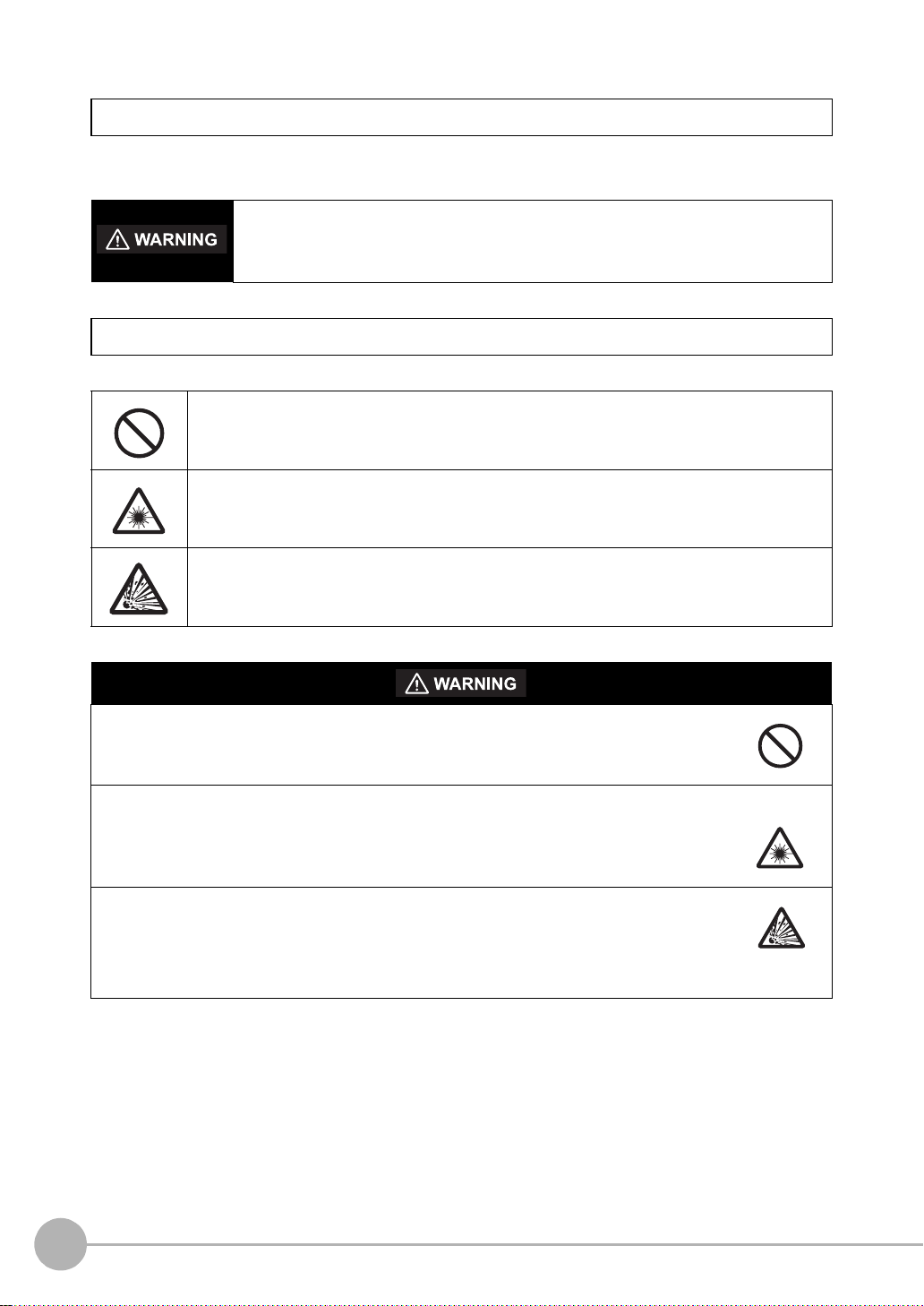
Meanings of Signal Words
The following signal words are used in this manual.
Indicates a potentially hazardous situation which, if not avoided, will result in minor or
moderate injury, or may result in serious injury or death. Additionally there may be
significant property damage.
Meanings of Alert Symbols
The following alert symbols are used in this manual
Indicates general proh ib iti ons for which there is no specific sym bo l.
Indicates the possibi lit y of la ser radiation.
Indicates the possibi lit y of explosion under specific cond iti ons .
This produc t is not designed or rated for ensuring safety of pers ons.
Do not use it for such purposes.
The camera with lighting emits visible light, which may adve rs ely affect th e eyes in rare instances.
Do not look direct ly into the light emit ted from the Camer a. When the subject is a specular
reflective object, protect your eyes from reflected light.
A lithium battery is buil t into the Con troller and m ay oc cas ionally comb ust, explod e, or burn if
not treated properly.
Dispose of the Con troller as industrial waste, and nev er disassemble, apply pressure that
would deform, heat to 10 0 °C or hi gher, or incinerate the Controller.
4
ZFX-C User’s Manual
Page 7

Precautions for Safe Use
The following points are important to ensure safety, so make sure that they are strictly observed.
1.Installation Environment
• Do not use the product in environ m ents where it can be exposed to inflamma bl e/ ex pl osive gas.
• To secure the safety of oper ation a nd maint enan ce, d o n ot ins tall the p roduc t cl ose t o high -v oltage de vices
and power devi ces.
• I nstall the product in such a way that its ven tilat io n holes are not blocked.
• Tighten mounting screws at the torque specified in this manual.
2.Power Supply and Wiring
• The voltage and AC power supply must be within the rated range (24 VDC ±10%).
• Reverse connection of the po w er supply is not allowed.
• Use the power supply within the rated load.
• H igh-voltage lines and power lin es must be wired separately from this product. Wiring them toge ther or
placing them in the sam e duct may cause induction, resulting in malfunction or damage.
• Use the product within the power supply voltage specified in this manual .
• U se a DC po wer sup ply with safet y measu res against high-vol tage spikes (sa fety extra lo w-voltage circ uits
on the secondary side).
• Tighten mounting screws at the torque specified in this manual.
3.Other
• Do not use this product in safety cir cui ts as sociated with nuclear power and human life.
• Do not disassemble, repair, modify, deform by pressure, or incinerate thi s pr od uct .
• Dispose of this product as indust rial waste.
• Connect the exclusive devices (Camera, Controller, Strobe Controller, Cable). The product might break
down or malfunction i f yo u use a part not included in the exclusive products.
• S hould you notice any abnormalities, imm ediately stop use, turn OFF the power suppl y, and contact your
OMRON representative.
4.Laws and Regulations, Standards
• This product complies with the fo llo w ing EC and EN directives:
EC Directive No.89/336/EEC
EN Standards EN61326: 1997+A1: 1998+A2: 2001+A3: 2003 (EMI: Class A)
ZFX-C User’s Manual
5
Page 8

Precautions for Correct Use
Observe the following precautions to prevent failure to operate, malfunctions, or undesirable effects on product
performance.
1.Installation Site
Do not install this product in locations subjected to the followin g conditions:
• Ambient temperature outside the rating
• Rapid temperature fluctuati on s (c ausing condensation)
• Relative humidity outside the range of 35 to 85%
• Direct vibration or shock
• Reflection of intense light (such as other laser beams, electric arc- w elding machines, or ultra-violet light )
• Direct sunlight or near heaters
• Strong magnetic or electric field
Also, do not install this product in locations subjected to the following conditions to ensure its protective
performance as described in the specifications:
• Presence of corrosive or flam m abl e gases
• Presence of dust, salt, or iron partic les
• Water, oil, or chemical fumes or spray, or mist atmospheres
2.Power Supply and Wiring
• When using a commercially av ai labl e switching regulator, make sure that the FG terminal is grounded.
• If surge currents are present in the power lines, connect surge absorbers that suit the operating
environment.
• B efore turning ON the power after the product is connected, make su re that the power supply voltage is
correct, there are no incorrect connections (e.g. load short-circuit) and the load current is appropriate.
Incorrect wiring may result in breakdown of the product.
• Before connecting/disc onnecting cables, make sure that the product i s turned OFF. The product may break
down if it is connected/di sc onnected while the power is ON.
• For cables, use only the exclusive products specified in this manual.
p.14, p.15
• Use only combinations of the Camera, Controller and Strobe Controller specified in this manual. Using other
combinations may cause malfunction or damage.
• D o not turn the power OFF in the following instances. Doing so will damage data that is in the process of
being saved.
- While data is being saved on t he Controller
- While data is being saved on the SD card
• T he LCD panel has b een mad e using prec ision tec hnolog y, and sometimes a few pixels a re missing i n the
panel. This is due to the structu re of the LC D panel, and i s not a malfunction.
• Do not remove the base from the Camera.
3.Maintenance and Inspection
Do not use thi nner, benzene, aceto ne or ker osene to clean the Camera and Con troller. If large dust particles
adhere to the Ca mera , us e a b lower brus h (u sed t o cl ean c amer a le nses) to blow them o ff. Do not use br eat h
from your mouth to blow the dust off. To remove dust particles from the Came ra, wipe gently wi th a soft cloth
(for cleaning lenses) moistened with a sma ll amount of alcohol. Do not use excessive force to wi pe off dust
particles. Scratches to the Cam er a m i ght cause error.
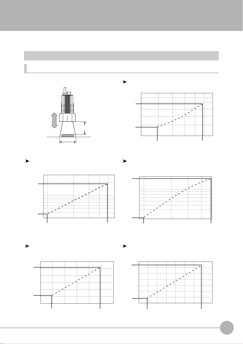
4.Ventilation Film
• D o not peel of the ventilation film or pr od it with a sharp-pointed object. Th is might impair its protective
structure.
• Do not cover the ventilation film. Doing so might cause the Came ra's front panel to cloud.
6
ZFX-C User’s Manual
Page 9

5.Optional Lighting Connector
Important
Note
When the optional lighting is not connected, be sure to attach the connector cap. Otherwise, its protective
structure might be impaire d.
6.Camera's Connector Cap
When using only one ca m er a, at tach the connector cap to cameras that are not in use.
Editor's Note
■ Meaning of Symbols
Menu items that ar e displayed on the Controller's LCD screen, and windows, dialog boxes and other GUI
elements displayed on the PC ar e in di cated enclosed by brackets "[ ]".
■ Visual Aids
Indicat es po in t s th at ar e im po rt a n t to ac h iev e t he f u ll pr od uct pe rf or ma nce ,
such as operational precautions.
Indicates application procedures.
Indicates pages where relat ed information can be found.
ZFX-C User’s Manual
7
Page 10

MEMO
8
ZFX-C User’s Manual
Page 11

CONTENTS
1.BEFORE USE
ZFX-C . . . . . . . . . . . . . . . . . . . . . . . . . . . . . . . . . . . . . . . . . . . . . . . . . . . . . . 14
System Configuration. . . . . . . . . . . . . . . . . . . . . . . . . . . . . . . . . . . . . . . . . . . . . . 14
Part Names and Functions . . . . . . . . . . . . . . . . . . . . . . . . . . . . . . . . . . . . . . . . . 16
Mounting and Connecting Devices . . . . . . . . . . . . . . . . . . . . . . . . . . . . . . 19
Installing Cameras. . . . . . . . . . . . . . . . . . . . . . . . . . . . . . . . . . . . . . . . . . . . . . . . 19
Installing the Controller . . . . . . . . . . . . . . . . . . . . . . . . . . . . . . . . . . . . . . . . . . . . 25
Connecting Devices. . . . . . . . . . . . . . . . . . . . . . . . . . . . . . . . . . . . . . . . . . . . . . . 28
Overview of Settings and Measurement. . . . . . . . . . . . . . . . . . . . . . . . . . 31
Operation Modes . . . . . . . . . . . . . . . . . . . . . . . . . . . . . . . . . . . . . . . . . . . . . . . . . 31
Outline of MENU mode . . . . . . . . . . . . . . . . . . . . . . . . . . . . . . . . . . . . . . . . . . . . 32
Measurement Items and Banks. . . . . . . . . . . . . . . . . . . . . . . . . . . . . . . . . . . . . . 33
Initializing Controller Settings. . . . . . . . . . . . . . . . . . . . . . . . . . . . . . . . . . . . . . . . 35
Saving Setup Data. . . . . . . . . . . . . . . . . . . . . . . . . . . . . . . . . . . . . . . . . . . . . . . . 36
2.BASIC OPERATIONS
Inspection Setup and Measurement . . . . . . . . . . . . . . . . . . . . . . . . . . . . . 38
Setting Measurement Conditions - MENU Mode. . . . . . . . . . . . . . . . . . . . . . . . . 38
Checking the Measurement Status - ADJ Mode . . . . . . . . . . . . . . . . . . . . . . . . . 42
Starting Measurement - RUN Mode. . . . . . . . . . . . . . . . . . . . . . . . . . . . . . . . . . . 42
Troubleshooting . . . . . . . . . . . . . . . . . . . . . . . . . . . . . . . . . . . . . . . . . . . . . 43
Clear Images Cannot be Obtained . . . . . . . . . . . . . . . . . . . . . . . . . . . . . . . . . . . 43
Measurement Target Cannot be Measured Accurately Due to Movement . . . . . 43
To Output Measurement Values to a PC or PLC. . . . . . . . . . . . . . . . . . . . . . . . . 44
To Output Positi on Information of Measurement Targets as Actual Coordinates
CONTENTS
. . . . . . 44
ZFX-C User’s Manual
9
Page 12

3.SETTING THE MEASUREMENT CONDITIONS
Setting Measurement Items . . . . . . . . . . . . . . . . . . . . . . . . . . . . . . . . . . . . 46
Shape Inspection. . . . . . . . . . . . . . . . . . . . . . . . . . . . . . . . . . . . . . . . . . . . . . . . . 46
Pattern Search . . . . . . . . . . . . . . . . . . . . . . . . . . . . . . . . . . . . . . . . . . . . . . . . . 46
Graphic Search . . . . . . . . . . . . . . . . . . . . . . . . . . . . . . . . . . . . . . . . . . . . . . . . 51
Flexible Search. . . . . . . . . . . . . . . . . . . . . . . . . . . . . . . . . . . . . . . . . . . . . . . . . 55
Sensitive Search . . . . . . . . . . . . . . . . . . . . . . . . . . . . . . . . . . . . . . . . . . . . . . . 58
Size Inspection. . . . . . . . . . . . . . . . . . . . . . . . . . . . . . . . . . . . . . . . . . . . . . . . . . . 62
Area . . . . . . . . . . . . . . . . . . . . . . . . . . . . . . . . . . . . . . . . . . . . . . . . . . . . . . . . . 62
Labeling . . . . . . . . . . . . . . . . . . . . . . . . . . . . . . . . . . . . . . . . . . . . . . . . . . . . . . 66
Edge Inspection. . . . . . . . . . . . . . . . . . . . . . . . . . . . . . . . . . . . . . . . . . . . . . . . . . 70
Position. . . . . . . . . . . . . . . . . . . . . . . . . . . . . . . . . . . . . . . . . . . . . . . . . . . . . . . 70
Width . . . . . . . . . . . . . . . . . . . . . . . . . . . . . . . . . . . . . . . . . . . . . . . . . . . . . . . . 75
Count . . . . . . . . . . . . . . . . . . . . . . . . . . . . . . . . . . . . . . . . . . . . . . . . . . . . . . . . 79
Bright/Color Inspection. . . . . . . . . . . . . . . . . . . . . . . . . . . . . . . . . . . . . . . . . . . . . 82
Bright . . . . . . . . . . . . . . . . . . . . . . . . . . . . . . . . . . . . . . . . . . . . . . . . . . . . . . . . 82
HUE . . . . . . . . . . . . . . . . . . . . . . . . . . . . . . . . . . . . . . . . . . . . . . . . . . . . . . . . . 84
Inspection by Individual Application. . . . . . . . . . . . . . . . . . . . . . . . . . . . . . . . . . . 87
Grouping. . . . . . . . . . . . . . . . . . . . . . . . . . . . . . . . . . . . . . . . . . . . . . . . . . . . . . 87
Defect. . . . . . . . . . . . . . . . . . . . . . . . . . . . . . . . . . . . . . . . . . . . . . . . . . . . . . . . 90
Image Adjustment . . . . . . . . . . . . . . . . . . . . . . . . . . . . . . . . . . . . . . . . . . . . . . . . 94
Cameras/Lighting . . . . . . . . . . . . . . . . . . . . . . . . . . . . . . . . . . . . . . . . . . . . 98
Shutter Speed . . . . . . . . . . . . . . . . . . . . . . . . . . . . . . . . . . . . . . . . . . . . . . . . . . . 98
Gain Setting. . . . . . . . . . . . . . . . . . . . . . . . . . . . . . . . . . . . . . . . . . . . . . . . . . . . . 98
Partial Function Settings . . . . . . . . . . . . . . . . . . . . . . . . . . . . . . . . . . . . . . . . . . . 99
Image Rate . . . . . . . . . . . . . . . . . . . . . . . . . . . . . . . . . . . . . . . . . . . . . . . . . . . . . 99
Light Control (Recipe Functions). . . . . . . . . . . . . . . . . . . . . . . . . . . . . . . . . . . . 100
Calibration . . . . . . . . . . . . . . . . . . . . . . . . . . . . . . . . . . . . . . . . . . . . . . . . . . . . . 101
Registering Images. . . . . . . . . . . . . . . . . . . . . . . . . . . . . . . . . . . . . . . . . . 106
Position Correction. . . . . . . . . . . . . . . . . . . . . . . . . . . . . . . . . . . . . . . . . . 107
Additional Functions. . . . . . . . . . . . . . . . . . . . . . . . . . . . . . . . . . . . . . . . . 109
Calculation. . . . . . . . . . . . . . . . . . . . . . . . . . . . . . . . . . . . . . . . . . . . . . . . . . . . . 1 09
Setting Reflection of Individual Results . . . . . . . . . . . . . . . . . . . . . . . . . . . . . . . 112
Logging Monitor. . . . . . . . . . . . . . . . . . . . . . . . . . . . . . . . . . . . . . . . . . . . . . . . . 113
10
ZFX-C User’s Manual
Page 13

4.FUNCTIONS USED DURING OPERATION
Monitoring the Measurement Status - RUN Mode . . . . . . . . . . . . . . . . . 116
Displaying Measurement Information . . . . . . . . . . . . . . . . . . . . . . . . . . . . . . . . 1 16
Switching the Image Display Method. . . . . . . . . . . . . . . . . . . . . . . . . . . . . . . . . 118
Checking/Adjusting the Measurement - ADJ Mode. . . . . . . . . . . . . . . . 119
Checking Measurement Status . . . . . . . . . . . . . . . . . . . . . . . . . . . . . . . . . . . . . 1 19
Switching the Image Display Method. . . . . . . . . . . . . . . . . . . . . . . . . . . . . . . . . 121
Using a Saved Image to Perform Re-measurement . . . . . . . . . . . . . . . . . . . . . 121
Adjusting Measurement Conditions. . . . . . . . . . . . . . . . . . . . . . . . . . . . . . . . . . 122
5.ADDITIONAL FUNCTIONS
Bank Settings . . . . . . . . . . . . . . . . . . . . . . . . . . . . . . . . . . . . . . . . . . . . . . 126
Bank Data Operations . . . . . . . . . . . . . . . . . . . . . . . . . . . . . . . . . . . . . . . . . . . . 1 27
Bank Group Operations. . . . . . . . . . . . . . . . . . . . . . . . . . . . . . . . . . . . . . . . . . . 127
System Settings . . . . . . . . . . . . . . . . . . . . . . . . . . . . . . . . . . . . . . . . . . . . 128
Camera Specifications. . . . . . . . . . . . . . . . . . . . . . . . . . . . . . . . . . . . . . . . . . . . 1 28
Communication Setup . . . . . . . . . . . . . . . . . . . . . . . . . . . . . . . . . . . . . . . . . . . . 1 28
Output Settings . . . . . . . . . . . . . . . . . . . . . . . . . . . . . . . . . . . . . . . . . . . . . . . . . 132
Display Settings. . . . . . . . . . . . . . . . . . . . . . . . . . . . . . . . . . . . . . . . . . . . . . . . . 134
Operation Settings. . . . . . . . . . . . . . . . . . . . . . . . . . . . . . . . . . . . . . . . . . . . . . . 135
Measurement Control Conditions . . . . . . . . . . . . . . . . . . . . . . . . . . . . . . . . . . . 137
Operation Conditions during Startup . . . . . . . . . . . . . . . . . . . . . . . . . . . . . . . . . 138
Setting/Changing the Display Language . . . . . . . . . . . . . . . . . . . . . . . . . . . . . . 138
Setting/Changing the Date. . . . . . . . . . . . . . . . . . . . . . . . . . . . . . . . . . . . . . . . . 139
Clearing Saved Images . . . . . . . . . . . . . . . . . . . . . . . . . . . . . . . . . . . . . . . . . . . 139
Tools. . . . . . . . . . . . . . . . . . . . . . . . . . . . . . . . . . . . . . . . . . . . . . . . . . . . . . 140
Saving/Loading Data . . . . . . . . . . . . . . . . . . . . . . . . . . . . . . . . . . . . . . . . . . . . . 1 40
SD Card Operations. . . . . . . . . . . . . . . . . . . . . . . . . . . . . . . . . . . . . . . . . . . . . . 141
Checking Density Distribution (Profile) . . . . . . . . . . . . . . . . . . . . . . . . . . . . . . . 141
Checking the Communication Status with External Devices . . . . . . . . . . . . . . . 1 42
Displaying the Controller Information. . . . . . . . . . . . . . . . . . . . . . . . . . . . . . . . . 143
CONTENTS
ZFX-C User’s Manual
11
Page 14

6.PARALLEL INTERFACE
Connection. . . . . . . . . . . . . . . . . . . . . . . . . . . . . . . . . . . . . . . . . . . . . . . . . 146
Parallel Connector Specifications . . . . . . . . . . . . . . . . . . . . . . . . . . . . . . . . . . . 1 46
Internal Specifications . . . . . . . . . . . . . . . . . . . . . . . . . . . . . . . . . . . . . . . 150
Signal I/O . . . . . . . . . . . . . . . . . . . . . . . . . . . . . . . . . . . . . . . . . . . . . . . . . . 152
Input Signal . . . . . . . . . . . . . . . . . . . . . . . . . . . . . . . . . . . . . . . . . . . . . . . . . . . . 152
Output Signal. . . . . . . . . . . . . . . . . . . . . . . . . . . . . . . . . . . . . . . . . . . . . . . . . . . 153
Timing Charts . . . . . . . . . . . . . . . . . . . . . . . . . . . . . . . . . . . . . . . . . . . . . . 156
Measurement (Handshaking OFF) . . . . . . . . . . . . . . . . . . . . . . . . . . . . . . . . . . 1 56
Measurement (Handshaking ON) . . . . . . . . . . . . . . . . . . . . . . . . . . . . . . . . . . . 159
Commands Other than for Measurement . . . . . . . . . . . . . . . . . . . . . . . . . . . . . 160
Signal Operation in terms of Measurement . . . . . . . . . . . . . . . . . . . . . . . . . . . . 161
7.APPENDICES
Error Messages and Corrective Actions. . . . . . . . . . . . . . . . . . . . . . . . . 166
List of Available Functions for Each Camera. . . . . . . . . . . . . . . . . . . . . 167
AUTO Setting. . . . . . . . . . . . . . . . . . . . . . . . . . . . . . . . . . . . . . . . . . . . . . . 168
AUTO Setting of Measurement Items . . . . . . . . . . . . . . . . . . . . . . . . . . . . . . . . 168
AUTO Setting in Individual Adjustment Screens . . . . . . . . . . . . . . . . . . . . . . . . 169
Specifications and External Dimensions . . . . . . . . . . . . . . . . . . . . . . . . 170
Camera . . . . . . . . . . . . . . . . . . . . . . . . . . . . . . . . . . . . . . . . . . . . . . . . . . . . . . . 170
Controller . . . . . . . . . . . . . . . . . . . . . . . . . . . . . . . . . . . . . . . . . . . . . . . . . . . . . . 176
Accessories & Options. . . . . . . . . . . . . . . . . . . . . . . . . . . . . . . . . . . . . . . . . . . . 178
LED Safety . . . . . . . . . . . . . . . . . . . . . . . . . . . . . . . . . . . . . . . . . . . . . . . . . 187
Requirements from Regulations and Standards . . . . . . . . . . . . . . . . . . 188
Summary of Requirements to Manufactures. . . . . . . . . . . . . . . . . . . . . . . . . . . 188
Summary of Requirements to User . . . . . . . . . . . . . . . . . . . . . . . . . . . . . . . . . . 190
Definitions of Laser Classification . . . . . . . . . . . . . . . . . . . . . . . . . . . . . . . . . . . 191
Basic Knowledge for Operation. . . . . . . . . . . . . . . . . . . . . . . . . . . . . . . . 192
Menu List . . . . . . . . . . . . . . . . . . . . . . . . . . . . . . . . . . . . . . . . . . . . . . . . . . 196
INDEX . . . . . . . . . . . . . . . . . . . . . . . . . . . . . . . . . . . . . . . . . . . . . . . . . . . . . 199
How Color Images are Processed . . . . . . . . . . . . . . . . . . . . . . . . . . . . . . 201
Color Filter. . . . . . . . . . . . . . . . . . . . . . . . . . . . . . . . . . . . . . . . . . . . . . . . . . . . . 202
Color Pickup. . . . . . . . . . . . . . . . . . . . . . . . . . . . . . . . . . . . . . . . . . . . . . . . . . . . 204
Hue, Saturation and Brightness Value. . . . . . . . . . . . . . . . . . . . . . . . . . . . . . . . 206
Version Upgrade Information. . . . . . . . . . . . . . . . . . . . . . . . . . . . . . . . . . 207
Revision History . . . . . . . . . . . . . . . . . . . . . . . . . . . . . . . . . . . . . . . . . . . . 208
12
ZFX-C User’s Manual
Page 15

BEFORE USE
ZFX-C 14
System Configuration 14
Part Names and Functions 16
Mounting and Connecting Devices 19
Installing Cameras 19
Installing the Controller 25
Connecting Devices 28
Overview of Settings and Measurement 31
Operation Modes 31
Outline of MENU mode 32
Measurement Items and Banks 33
Initializing Controller Settings 35
Saving Setup Data 36
1
BEFORE USE
Page 16
ZFX-C
3 42
1
The ZFX-C is a series of visi on sens ors th at sen ses obje cts by the ir “surfa ces. “ Obje cts captur ed by a ca mer a
can be checked on the built-in 3.5-inch LCD monitor.
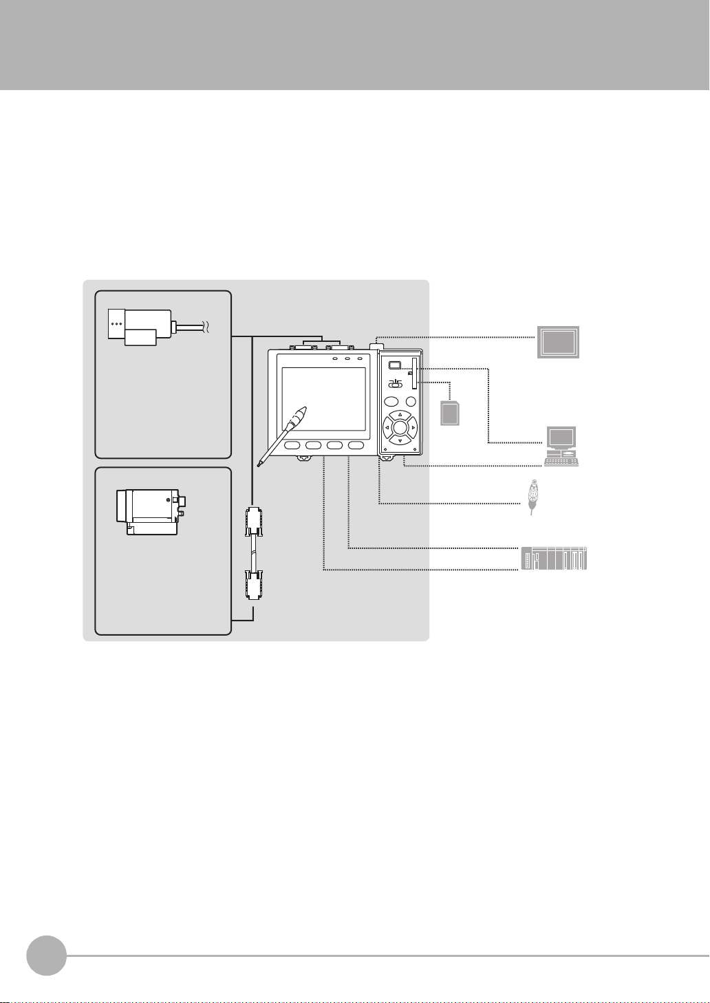
System Configuration
Basically, the ZFX-C is configured by the Controller and the camera.
Other external devices can be selected to be used in combination wit h the ZFX-C according to the user’s
specific requireme nts.
Cameras with lighting
(cable built-in)
- Color camera
ZFX-SC10/SC50/SC50W
ZFX-SC90/SC90W
ZFX-SC150/SC150W
- Monochrome camera
ZFX-SR10/SR50
Camera only
- Color camera
ZFX-SC
- Monochrome camera
ZFX-S
A CCTV lens and light
source will be required.
Touch pen
(*1)
Camera cable
ZFX-VS/VSR
Controller
ZFX-C20/C25
Monitor cable
FZ-VM
SD Card (*4)
RS-232C cable
ZFX-XPT2A
RS-422 cable
ZFX-XPT2B
Parallel I/O cable
ZFX-VP
LCD monitor (option)
FZ-M08 (*2)
PC
USB
Ethemet
Console
ZFX-KP
PLC
(*3)
*1: The Touch Pen (ZFX-T P) is su pplied with the Controller.
*2: The same image as in th e C ontroller's LCD monitor can be displayed in the LCD monitor (option).
*3: The console can be us ed instead of the Controller's keys and menu buttons.
*4: Conforms to the SD Card “ P hy si cal layer specifications 1.01.”
File format: FAT16
14
ZFX-C
ZFX-C User’s Manual
Page 17
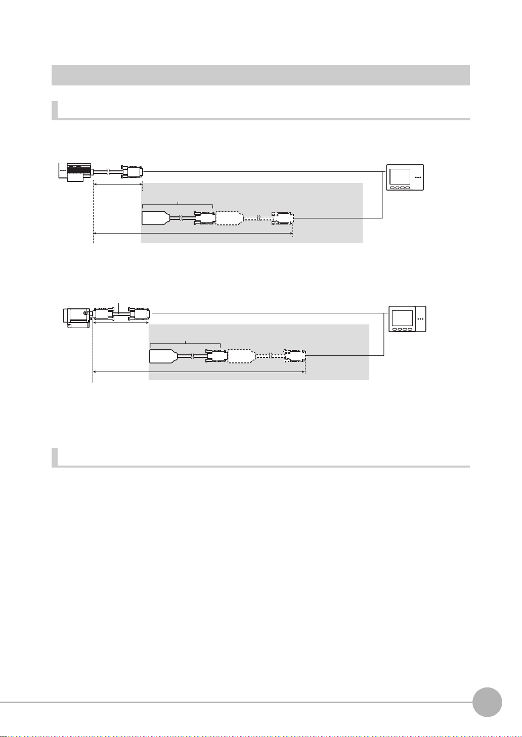
Options
Cameras with lighting
2 m
Extension cable
(cable built-in)
ZFX-XC_A/XC_AR
3m/8m
(*1)
5 to 18 m
Extension cable
ZFX-XC_A/XC_AR
3m/8m
(*1,*2)
Camera only
3 m/8 m
Camera cable
ZFX-VS/VSR
8 to 19 m
Extension cable for connecting cameras and the Controller
1
BEFORE USE
*1: Up to two ZFX-XC_A/XC-AR can be connected between the camera cable and the Controller.
*2: Two ZFX-XC8A cannot be connected to each other when used with ZFX-VS (8 m.)
Optional lighting
The following optional light in g ca n be connected to ZFX-SC50/SC50 W /SC90/SC90W.
• Bar lighting ZFV-LTL01
• Bar double-lighting ZFV-LTL02
• Bar low-angle lighting ZFV-LTL04
• Light Source for Through-beam Lighting ZFV-LTF01
ZFX-C User’s Manual
ZFX-C
15
Page 18
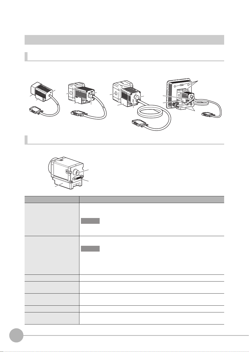
Part Names and Functions
ZFXSC10/SR10/SR50
ZFX-SC50/SC50W
ZFX-SC90/SC90W ZFX-SC150/SC150W
ZFX-S/SC
Cameras
Cameras with lighting
(2)
(2)
(4)
(3)
(2)
(4)
(1)
(3)
(2)
(4)
(3)
(1)
(3)
(4)
(2)
Camera only (C-mount type)
(5)
(6)
(7)
Name. Description
(1)Optional lighting connector This connector is used to connect an optional lighting. (ZFX-SC50/SC50W/SC90/
SC90W)
Important
When no optional lighting is used, make sure that the connector is covered with the
cap. If not, water-resistant performance will be deteriorated.
(2)Ventilation film This film prevents the front panel from condensation.
(3)Focus adjustment control This control is used for adjusting the focus of the image.
(4)Mounting fixture This mounting fixture is used for fastening the camera when installing it. The mount-
(5)Lighting connector This connector is used to connect external lighting (Strobe Controller: 3Z4S-LT
(6)Camera cable connector
(7)Camera mounting base
16
ZFX-C
Important
• Do not peel off or probe the ventilation film with a sharp-pointed object. If you do
that the protective structure rating may no longer be satisfied.
• Do not cover the ventilation film rating. Doing so might cause the front panel to be
condensed.
ing fixture can be installed on all of the four mounting surfaces.
MLEK-C100E1TSX).
This connector is used for connecting to the Con troller via a camera cable (ZFX-VS/ VSR).
This camera mounting base is fastened with screws to hold the camera in place. The camera
mounting base can be installed on all of the four mounting surfaces.
ZFX-C User’s Manual
Page 19
PULL OPEN
1234
OMRON
ZFX-C10
OUTPUT
RUN
ERROR
ENABLE
MENU RUN
SD
CARD
ADJ
USB
AUTO ESC
SET
ETHERNET
PARALLEL1
CONSOLE
RS-232C
PARALLEL0
CAMERA1
RGB
CAMERA2
(1)
(4)
(2)
(3)
(9)
(5)
(1)
(1)
(4) (5)
(2) (3)
(2)
(6)
(7)
(8)
Operation
panel cover
Front
Top
Bottom
Controller
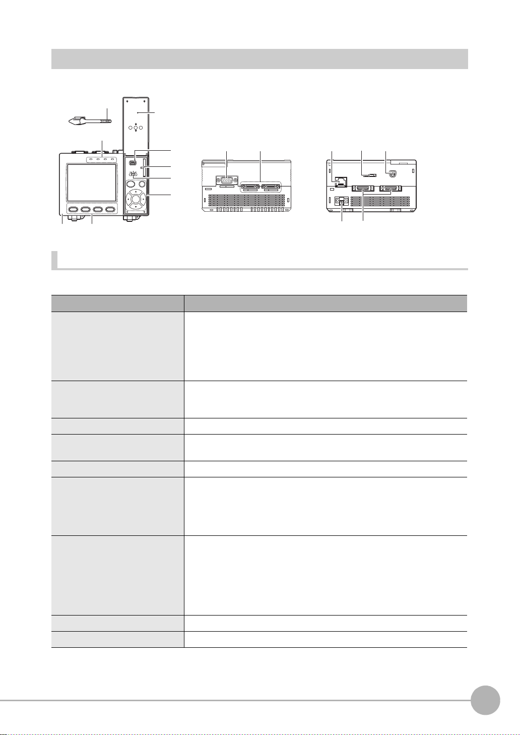
Front
Name Function
(1) Indicator “Measuring” indicator (RUN): Lights in green when in the RUN mode.
Error indicator (ERROR): Lights in red when an error occurs.
Judgment indicator (OUTPUT): Lights in orange when the judgment res ult is
OK or NG according to the setting. (Note)
Trigger indicator (ENABLE): Lights in blue when the ZFX-C is ready for the
measurement trigger input.
(2) LCD monitor/touch panel The LCD monitor displays setup menus and images captured from the cam-
eras. Various settings can be made on the touch panel by tapping menu but-
tons in the LCD monitor using the touch pen.
(3) Function keys Specific functions are allocated to the Function keys.
(4) Touch pen The touch pen is used to operate the touch panel. This pen can be attached to
the Controller by tying its strap to the strap holder for the touch pen.
(5) USB port This port is for connecting to a personal computer via a USB cable.
(6) SD card slot This slot is for inserting the SD Card.
When the SD Card is inserted, the SD mark is displayed at the top right of the
screen.
Blue SD mark: The SD card is inserted but not being accessed.
Red SD mark: The SD card is being accessed.
(7) Mode switch This switch selects the operation mode.
MENU: Select this mode when setting measurement conditions.
ADJ: Select this mode when adjus ting setting parameters as necessary refer-
encing the image and values displayed on the LCD monitor during con-
(8) Control keys These keys are used to perform operations without the use of the touch pen.
(9) Strap holder for touch pen This holder is for attaching the touch pen.
Note: The judgment result is output to the OR signal via the parallel interface.
ZFX-C User’s Manual
tinuous test measurement (measurement without measurement data
output to external devices).
RUN: Select this mode when performing measurement.
ZFX-C
1
BEFORE USE
17
Page 20
Top
Name Function
(1) Monitor connector This connector is for connecting to the LCD monitor (option) via a monitor
cable.
(2) Camera connector This connector is for connecting to a camera.
Bottom
Name Function
(1) Ethernet port This port is for connecting to a personal computer via a 100Base-TX/10Base-T
cable.
(2) RS-232C/422 connector This connector is for connecting to a PLC via an RS-232C or an RS-422 cable.
p.14
(3) Console connector
(4) Power connector
(5)Parallel port This port is for connecting to devices such as a PLC using the parallel cable.
This port is for connecting to the Console.
This connector is for connecting to the DC power supply.
p.14
p.28
, p.146
p.14
Important
• Attach the connector caps to connectors that are not in use to prevent dust or dirt from getting inside the connectors
and to prevent the Controller from static electricity.
18
ZFX-C
ZFX-C User’s Manual
Page 21
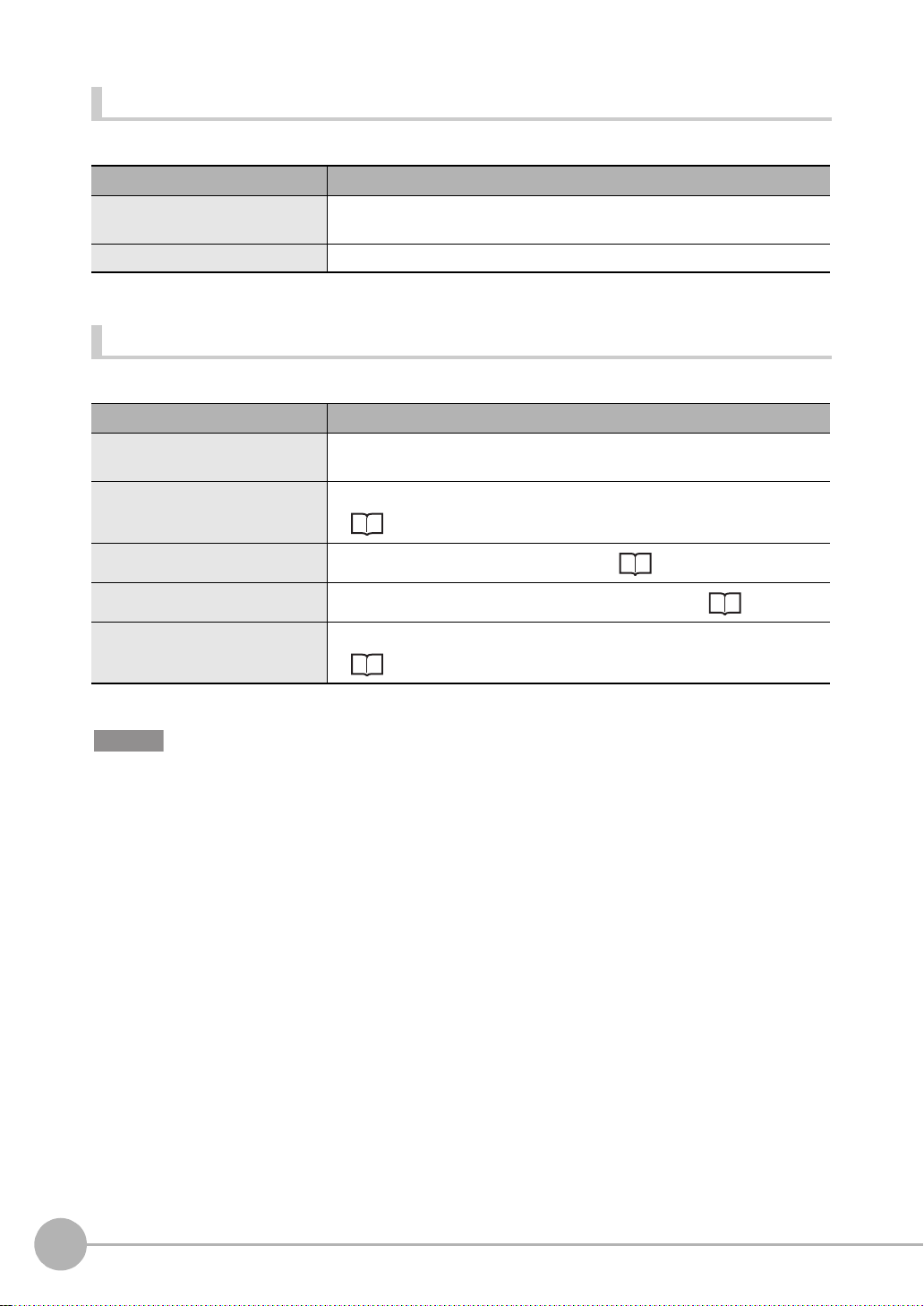
Mounting and Connecting Devices
Setting distance (L)
Detection range (H)
Setting distance L (mm)
Detection range H (mm)
9
9.8 49
60
30
38
100
194
300
Setting distance L (mm)
Detection range H (mm)
Setting distance L (mm)
Detection range H (mm)
Setting distance L (mm)
Detection range H (mm)
70
89
10040
40
67
100
142
160
49
Setting distance L (mm)
Detection range H (mm)
Installing Cameras
Camera with Lighting
Optical chart
ZFX-SC10/SR10
60
50
49
34
0
4.9
ZFX-SR50 ZFX-SC50/SC50W
190
187
100
1
BEFORE USE
104
8.9
ZFX-SC90/SC90W ZFX-SC150/SC150W
ZFX-C User’s Manual
31
227
115
30
240
180
100
9.8
12080
89
Mounting and Connecting Devices
49
160
148
19
Page 22
• The lens has a fixed focal point. The actual detection range and focal point vary from lens to lens, so adjust the
Note
Hooks
Grooves on camera
Mounting
fixture
Mounting fixture
distance to the measurement target after replacing the lens or camera.
• The camera m ounting distance listed in the following tables is an approximate value. Mount the Camera so that
the distance to the measurement target can be adjusted easily.
• If the object size and detection range are incompatible, use a combination of a camera (without lighting), standard
CCTV lens and light source.
Camera Only p.22
Installing the mounting fixture
The mounting fixture can be installed on all of the four mounting surf ac es.
1 Align the two hooks on one side of the mounting fix-
ture with the two grooves on the camera body.
2 Push the other hook down until it is snapped into
place.
Make sure that the mounting fixture is firmly fixed on the
camera.
3 Fasten the mount ing fixtur e at the moun ting locatio n
with screws.
Tightening torque
M4: 1.2 N•m
1/4”-20 UNC: 2.6 N•m
Removal procedure
20
Mounting and Connecting Devices
1 Insert a screwdriver into the gap (one of the two gaps) be-
tween the mounting fixture and the camera case, and remove the mounting fixture
.
ZFX-C User’s Manual
Page 23
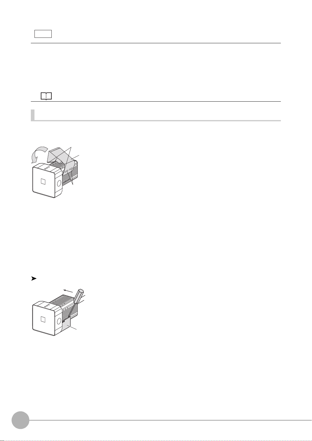
Adjusting the camera focus
Setting distance (L)
Detection range (H)
Focus
adjustment
control
Note
1 Adjust the distance between the camera and the mea-
surement target and fasten the camera.
Refer to the optical chart and set the camera in a position
so that t he ar ea t o be che cked is with in t he de tect io n ar ea
(LCD monitor).
Optical chart p.19
2 Tu rn the focus ad j ustment control to the left and right
to adjust the focus.
First turn the focus adjustment control slightly to the left and right, to make sure that the Focus adjustment control is
not at the upper or lower limit positions. Do not exert unnecessary force to turn the control at the upper or lower limit
positions as this might damage the control.
(For ZFX-SC90_/SC150_, the control stops turning at the nearest position. It turns free at the farthest position.)
1
BEFORE USE
ZFX-C User’s Manual
Mounting and Connecting Devices
21
Page 24
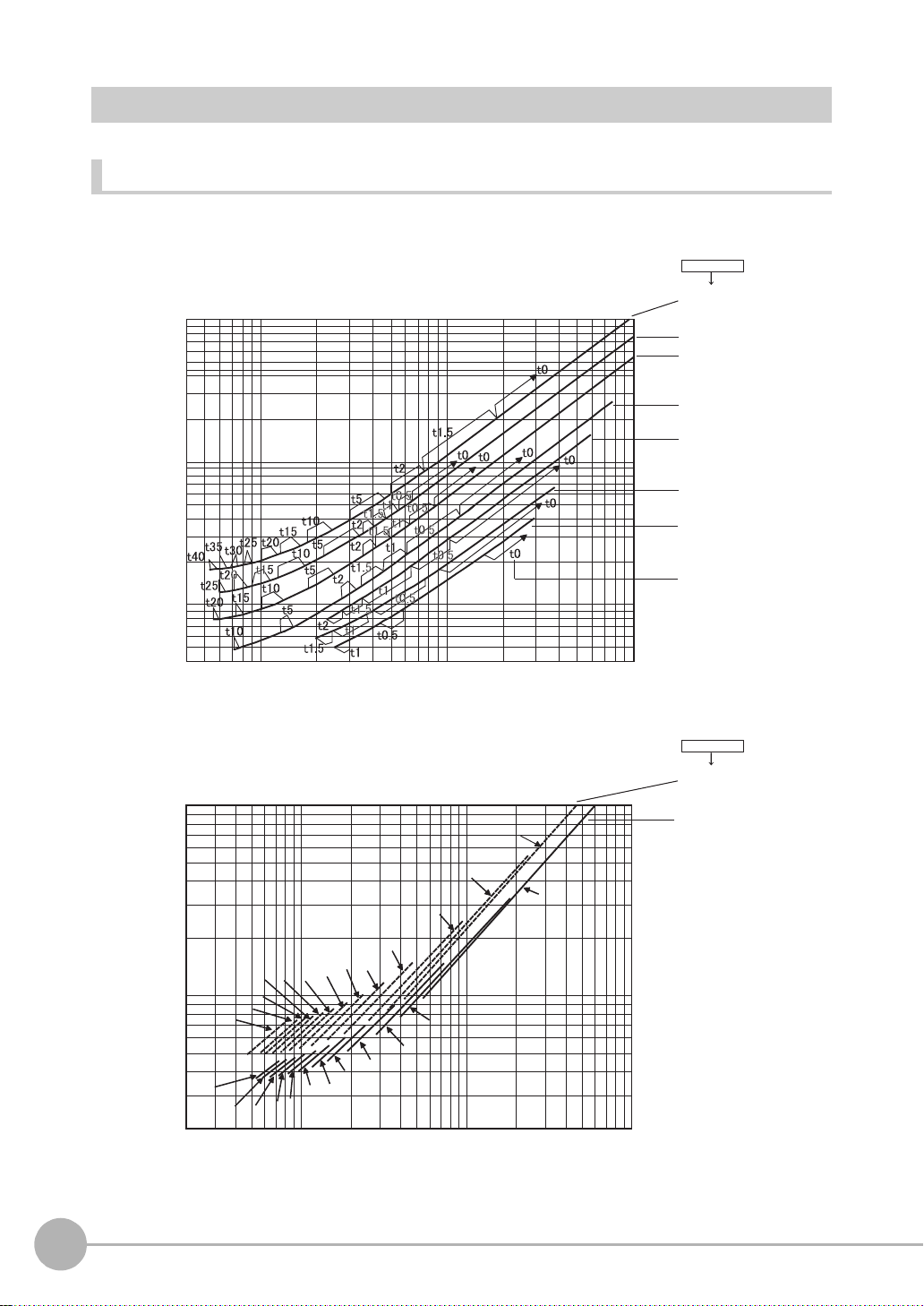
40
100
1000
10000
4 10 100 1000
Detection range(mm)
ML-0614
ML-0813
ML-1214
ML-1614
ML-2514
ML-3519
ML-5018
Lens model
3Z4S-LE
Lens model
3Z4S-LE
Camera distance A(mm)Camera distance A(mm)
200
1000
10000
2 10 100 1000
t2
t5
t10
t15
t20
t30
t35
t50
t45
t5
t10
t15
t20
t25
t30
t40
t35
t45
t50
t60
t0
t2
t40
t25
t0
ML-7527
ML-10035
t: Extension tube
Example
t0: Extension tube
is not required.
t5: 5-mm extension
tube is required.
Camera Only
Optical chart
The values in the following chart are approximations, and t he C amera must be adjusted after it is mount ed.
22
Mounting and Connecting Devices
ZFX-C User’s Manual
Page 25
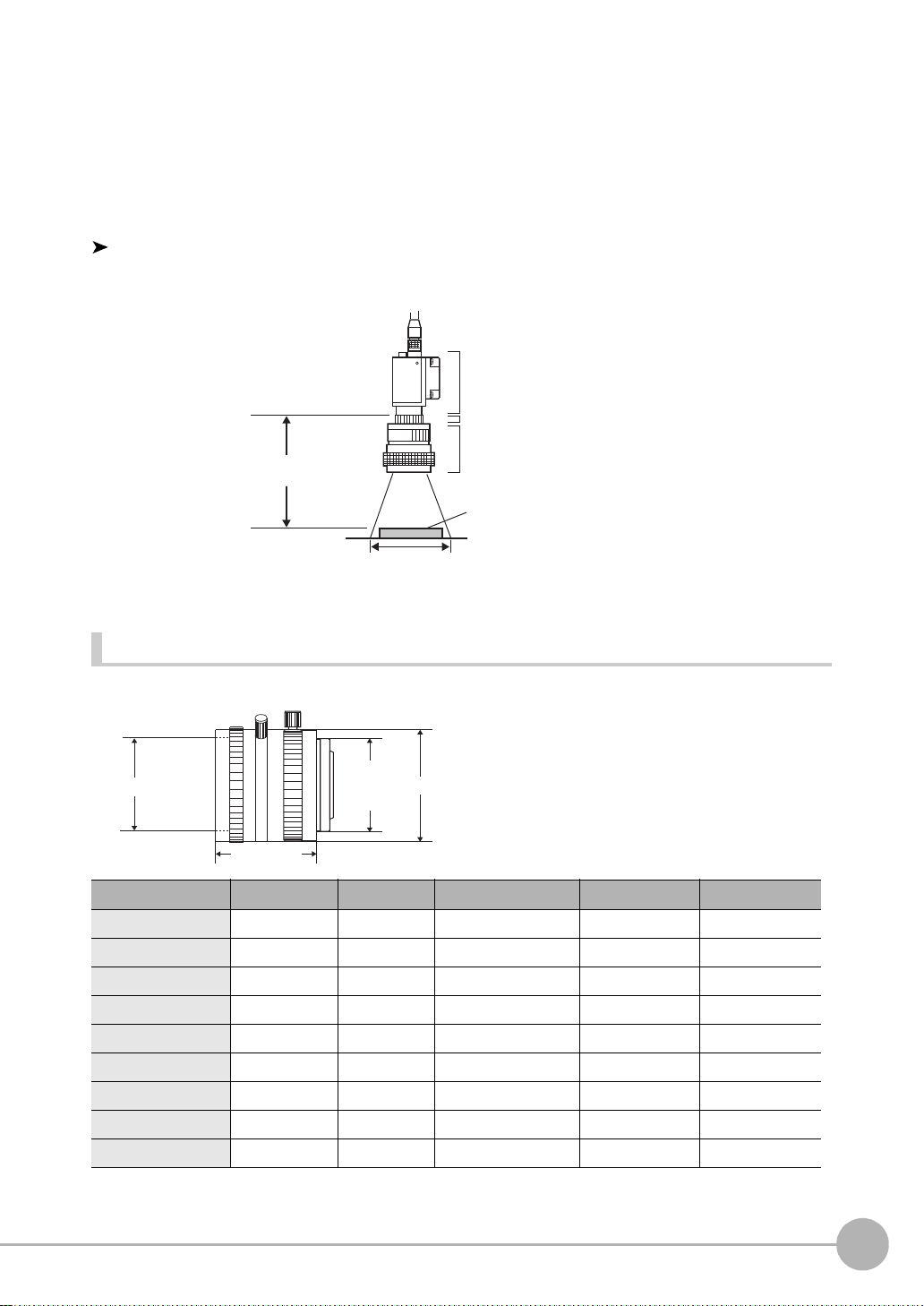
The X axis of the optical chart shows detection range L (mm), and the Y axis shows the camera distance A
1-32 UNF
(C-mount
thread)
Filter thread
Total length
Max. dia.
(mm). The curves on the optical chart show the relationship between the detection range and camera distance
for each CCTV lens. The values are significantly differen t for each lens, so double-check t he model of the lens
before using the g raph. The “t” value s indicate the l engths of the Extension Tubes. The value “t0” show s the
case where an Extensio n Tube is not required and the value “t5.0” shows the case where a 5-mm Extension
Tube is used.
1
Example
When a 3Z4S-LE ML-5018 CCTV Lens is being used and a detection range of 40 mm is required at the
measurement target, a camera distance of 500 mm and 5-mm Extension Tube are required.
Camera
Extension Tube t_ (mm)
Lens
Camera distance A (mm)
Measurement object
Detection range L (mm)
Lenses and lens diameters
BEFORE USE
Lens Focal length Brightness
3Z4S-LE ML-0614 6 mm F1.4 30 mm dia. 30 mm M27 P0.5
3Z4S-LE ML-0813 8 mm F1.3 30 mm dia. 34.5 mm M25.5 P0.5
3Z4S-LE ML-1214 12 mm F1.4 30 mm dia. 34.5 mm M27 P0.5
3Z4S-LE ML-1614 16 mm F1.4 30 mm dia. 24.5 mm M27 P0.5
3Z4S-LE ML-2514 25 mm F1.4 30 mm dia. 24.5 mm M27 P0.5
3Z4S-LE ML-3519 35 mm F1.9 30 mm dia. 29 mm M27 P0.5
3Z4S-LE ML-5018 50 mm F1.8 32 mm dia. 37 mm M30.5 P0.5
3Z4S-LE ML-7527 75 mm F2.7 32 mm dia. 42.5 mm M30.5 P0.5
3Z4S-LE ML-10035 100 mm F3.5 32 mm dia. 43.9 mm M30.5 P0.5
ZFX-C User’s Manual
Maximum outer diameter
Total len gth Filter size
Mounting and Connecting Devices
23
Page 26
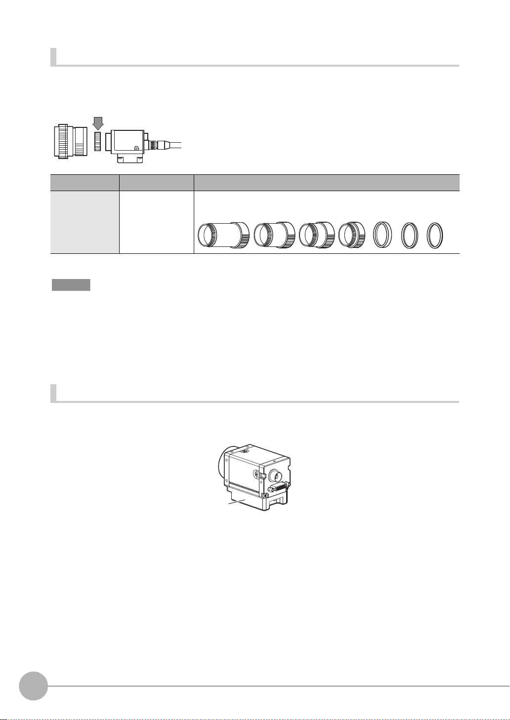
Extension Tubes
L
m
Camera Mounting Base
One or more Ext ensi on Tubes can be inserte d b etwee n the len s and the Cam era to focus the C am era im age.
Use a combination of on e or mo re of the seven tubes to achieve the required length.
Extension Tube
Model
3Z4S-LE ML-EXR 31 dia. Set of 7 tubes
Important
• Do not use the 0.5-mm, 1.0-mm and 2.0-mm Extension Tubes attached to each other. Since these Extension Tubes
are placed over the threaded section of the Lens or other Extension Tube, the connection may loosen when more
than one 0.5-mm, 1.0-mm or 2.0-mm Extension Tube are used together.
• Reinforcement may be required for combinations of Extension Tubes exceeding 30 mm if the Camera is subject to
vibration.
Maximum outer diameter
Length
ength: 40 mm 20 mm 10 mm 5 mm 1 mm2 mm 0.5 m
Installing the Camera Mounting Base
The camera mounting base moun ted on the bot tom of the cam era can be insta lled on all of the four mountin g
surfaces. To change the mounting surface, remove the thr ee mounting screws (M2 x 6) from the cam e ra.
• Tightening torque when fastening the camera mounting base at the mounting location
M4: 1.2 N•m
1/4”-20 UNC: 2.6 N•m
24
Mounting and Connecting Devices
ZFX-C User’s Manual
Page 27
Installing the Controller
Important
Min.
50 mm
Min.
15 mm
When installing Controller only:
When installing the Controller With the Exhaust Unit
attached:
Min.
50 mm
Min. 15 mm
Installation Precautions
To improve heat radiatio n, in stall the C ont r ol ler only in the orientation show below.
1
Right
Do not install the Controller in the following orientations.
Wrong Wrong
• Install the Controller so that the distance between the Controller and other devices is at least the dimensions shown
in the figure below to improve the ventilation.
BEFORE USE
• Keep the ambient temperature less than 50 °C. If the ambient temperature is higher than 50 °C, install a fan forced
cooling system or an air conditioner to keep the temperature lower than 50 °C.
• Avoid mounting on a panel, in which high-voltage emitting devices are installed to prevent ZFX-C operation from
being affected by noise.
• Allow at least 10 m between the Controller and power lines to keep noise at a low level in the operating environment.
ZFX-C User’s Manual
Mounting and Connecting Devices
25
Page 28
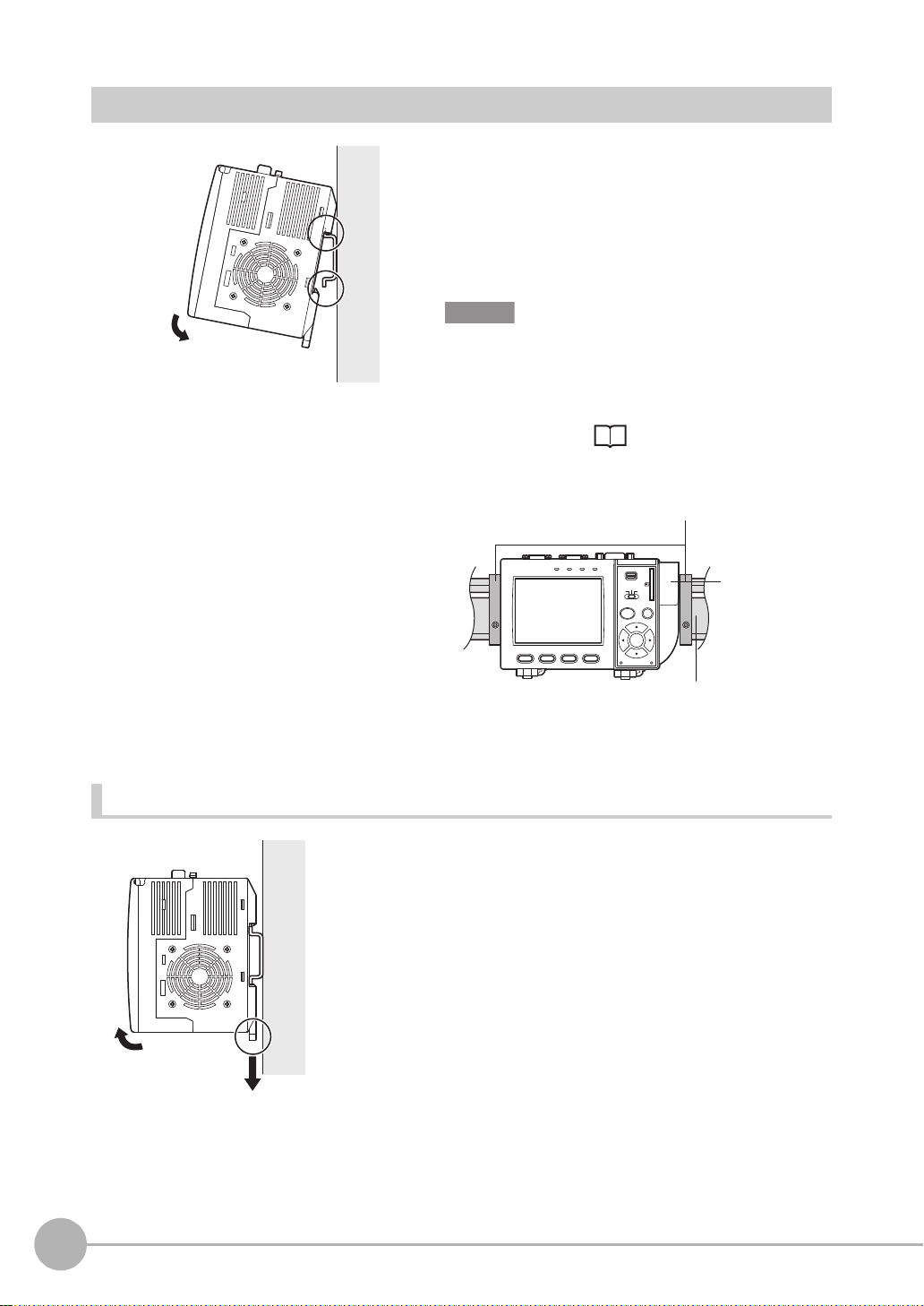
Installing on the DIN Track
DIN track (sold separately)
End Plate (sold separately)
PFP-M
PFP-100N (1 m)
PFP-50N (0.5 m)
PFP-100N2 (1 m)
Exhaust Unit
1
2
1 Hook the Controller’s upper hook onto the DIN track.
1
2 Push the Control ler down o nto the DIN track until its
lower hook is snapped into place.
2
Important
•Attach the End Plate (sold separately) to both sides of the
Controller on the DIN track.
•Attach the Exhaust Unit (supplied) to the Controller when
installing other devices adjacently on the same DIN track
as the Controller.
OMRON
OUTPUT
ZFX-C10
1234
RUN
p.20
USB
ENABLE
ERROR
ADJ
MENU RUN
AUTO ESC
SET
PULL OPEN
SD
CARD
Removing procedure
1 Pull the Controller’s lower hook downwards.
2 Lift up the Controller from its bottom to remove it from
the DIN track.
26
Mounting and Connecting Devices
ZFX-C User’s Manual
Page 29
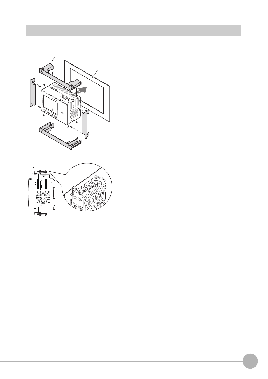
Mounting on a Panel
1
1
2
2
3
Panel mount adapters
Panel
Mounting bracket
1 Install the long Panel Mount Adapters on the four
holes on the Controller.
1
BEFORE USE
2 Install the short Panel Mount Adapters on the two
holes on t he long Panel Mou nt Adapter.
3 Install the Controller with Mount Adapters attached
onto the panel from the front.
4 Hook the hooks of the mounting bracket onto the two
4
holes (two each at top and bottom) of the longer
Mount Adapters and tighten the screws .
Tightening torque: 1.2 N•m.
5 Make sure that the Controller is firmly fixed on the
panel.
ZFX-C User’s Manual
Mounting and Connecting Devices
27
Page 30
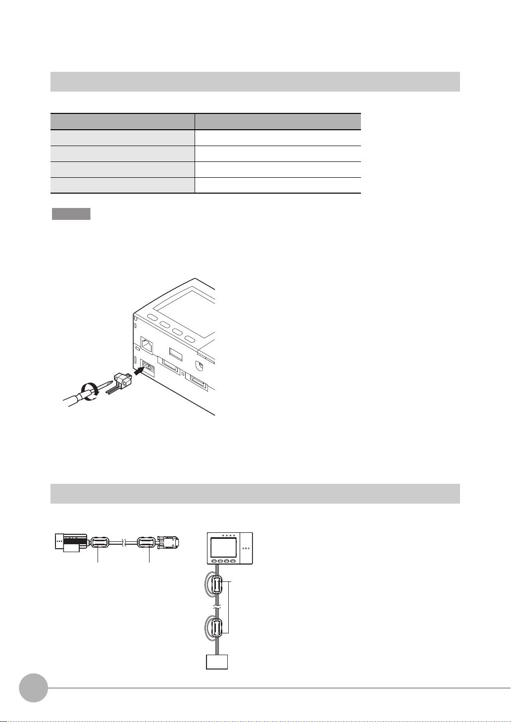
Connecting Devices
24 VDC
-
+
When attaching ferrite cores to the Controller's power
cable, pass the cable once through each ferrite core.
Connecting the Controller to the Power Supply
Use a power supply that meets the following specifications.
Item Specification
Power supply voltage Approx. 24 VDC (21.6 to 26.4 VDC)
Output current 1.5 A min.
Recommended power supply S8VS-06024 (24 VDC, 2.5 A)
Recommended electric wire size 0.14 to 1.5 mm2 (max. 1 m)
Important
Use a DC power supply with countermeasures against high voltages (safe extra low-voltage circuits on the secondary
side). If the system must meet UL standards, use a UL class II power supply.
1 Loosen the t wo screws on the top of the Power con-
nector (male) using a flat-blade screwdriver.
2 Insert the DC power terminal (wire) into the Power
connector (male) and tighten th e two screws on the
top of the Power connector to fasten the power terminal with the screwdriver.
Tightening torque: 0.22 to 0.25 N•m.
3 Plug the Pow er c onne ct or (male) in to the C ont ro ller’s
Power connector (fem ale).
4
Tighten the two screws on the left and right of the Power
connector (male) with the screwdriver to fasten it.
Tightening torque: 0.22 to 0.25 N•m.
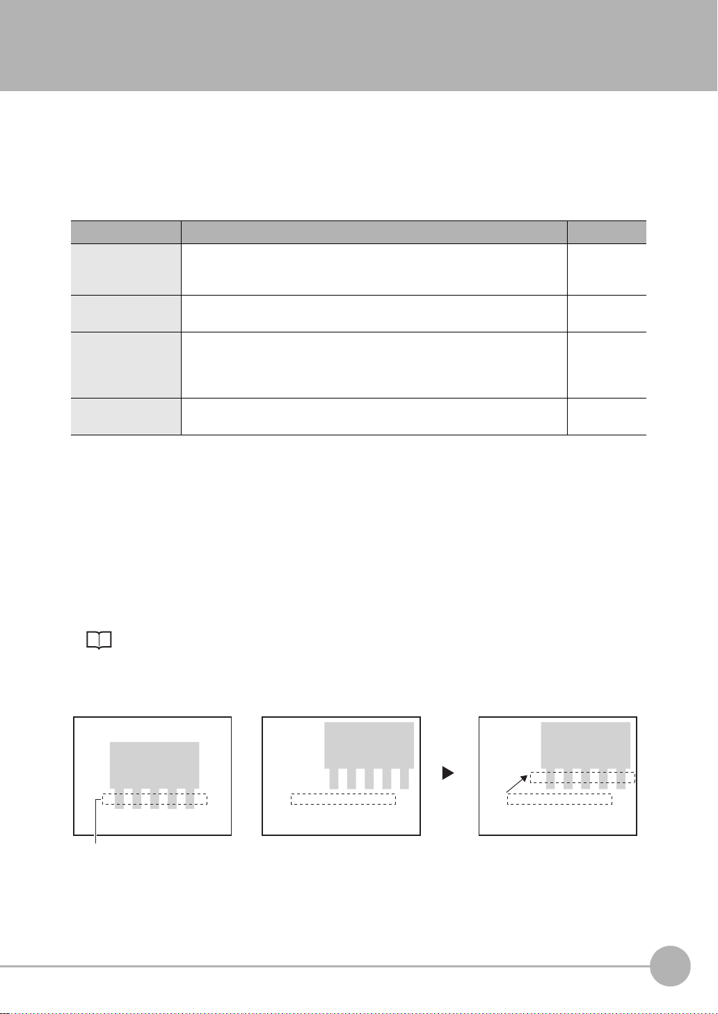
Attaching Ferrite Cores
Attach fer rite cores (sup pl ied) to both ends of the c am era's cable and th e Co ntroller's po wer cable, respectively.
Ferrite coreFerrite core
Ferrte core
-
+
DC power
supply
28
Mounting and Connecting Devices
ZFX-C User’s Manual
Page 31

Connecting the Camera to the Controller
1Insert the camera’s connector into the Controller’s
Camera connector.
1
2Tighten the two fastening screws of the Controller ’s
Camera connector.
Tightening torque: 0.15 N•m.
Important
•Do not touch the terminals inside the connector.
•Fasten the connector while making sure that it is not subjected
to vibration or shock.
•Do not mount the Controller in such a way that a load is steadily
applied on the connector, for example, with tension applied to
the cables.
To extend the installation distance between cameras and the Controller, see p.15
Disconnection procedure
Loosen the fastenin g screws (two location s) to unlock the camer a’s cable, and then pull the camera’s cable
connector straight out .
Important
• Be sure to hold the connector of the camera to disconnect it. Failure to do so may damage the camera’s cable.
• Do not touch the terminals inside the connector.
BEFORE USE
ZFX-C User’s Manual
Mounting and Connecting Devices
29
Page 32

Connecting the Optional Lighting to the Camera
Remove the cap from the optional lighting connector on the rear of the camera.
Connector of the
optional lighting
Touch Pen Holder
Exhaust Unit
The optional lightin g can be mo unted to the rear connector o f the camera (ZFX-SC50_/S C90_) with a single
motion. Since the power is supplied from the camera side, no power supply is required for the optional lighting.
Attaching the Exhaust Unit to the Controller
Attach the Exhaust Unit (supplied) to the Controller when installing other devices next to the Controller on the same
DIN track. The Exhaust Unit also serves as the Touch Pen Holder
1 Attach the Exhaust Unit to the four mounting holes on
the Controller.
30
Mounting and Connecting Devices
ZFX-C User’s Manual
Page 33

Overview of Settings and Measurement
ADJ
MENU
RUN
Mode switch
Top Screen
Top Screen
Top Screen
Operation Modes
The ZFX-C has the f ollowing three modes. Switch to the desired
MENU
ADJ
RUN
mode before y ou start operation. To switch the operation mode,
use the mode switch.
Mode Description
MENU mode This mode is for setting the measurement
conditions. The easy-to-follow icon-based
display allows operations to be performed
intuitively.
ADJ mode This mode is for checking the measure-
ment status and adjusting conditions.
Measurement results are only displayed
on the monitor and are not output.
LIVE
Bank
Tool
353ms
OK
Camera 0
0.Bank00
0.Pattern Search
Judge OK
Correlation 92
Position X 462
Position Y 352
Angle 15
Top menu
TEA
System
Setup
Individual result
1
BEFORE USE
Save
TEA
RUN mode This mode is used for performing actual
measurement. Measurement results are
displayed on the monitor and output.
ZFX-C User’s Manual
Previous Next Dsplay SW Adjust
Individual result
353ms
OK
Camera 0
0.Bank00
0.Pattern Search
Judge OK
Correlation 92
Position X 462
Position Y 352
Angle 15
Previous Next Dsplay SW Capture
TE
A
Overview of Settings and Measurement
31
Page 34

Outline of MENU mode
These menus are displayed when the Controller is turned
on.
These menus are used for setting measurement
conditions.
This selects measurement items and sets the measurement region. Up to 128 measurement regions can be set.
This returns to the top menu.
This returns to the setup menu.
The MENU mode is br oadly divided into three levels. The icon s used for basic setup are displayed in th e
center.
Use icons other than those i n t he center whenever required.
To p Menu
Top menu
Bank
Setup
System
Tool
Setup Menu
Setup
Cameras
Register
Item
Position
Top Menu
Measurement item Menu
Select measurement item
Save
Add func
32
Overview of Settings an d M eas urement
Img Adj
Region
Detail
Limits
Setup menu
ZFX-C User’s Manual
Page 35

Measurement Items and Banks
Cap color
(item 0: Hue inspection)
Label attached state
(item 1: Pattern Search)
Label lettering
(item 2: Sensitive Search)
Bank 0Bank 2 Bank 3 Bank 31
For inspection of
product A
For inspection of
product B
For inspection of
product C
For inspection of
product Z
Measuring Multiple Locations
Up to 128 locations in a single measurement image can be measured. A measurement type is called an "item,"
and desired measurement types are assigned to items 0 to 127.
1
BEFORE USE
Data for Change of Device Setup
If you register bank data for eac h individu al pr oduct , you ca n reduc e the time req uired fo r chan ging the devic e
setup as all you need to do is to se le ct di fferent bank data to change the measurement conditions.
ZFX-C User’s Manual
Overview of Settings and Measurement
33
Page 36

Relationship between Items and Bank Data
.
Position correction function
setup information
.
Output condition setup
information
.
Region information
.
Measurement item information
.
Image adjustment information
.
Judgment threshold value information
Bank 0
Bank 1
Bank 2
Bank 31
Item 0
Item 1
Item 2
Item 127
Up to 128 items c an be r egistered to a single ba nk data. Up to 32 bank data can be set to a nd saved o n the
ZFX.
Note
• If you use the bank group function, you can set up to 1024 banks.
Bank Settings p.126
• Bank and items can be given any name up to 16 characters.
Bank and item names make it eas ier to recognize which measurement is being performed when multiple items
and banks have been set.
34
Overview of Settings an d M eas urement
ZFX-C User’s Manual
Page 37

Initializing Controller Settings
ADJ
MENU
RUN
Mode switch
Important
The settings of all banks and system settings (excluding the display language set ting) a re initialized regardless of the
currently selected bank No. To save the settings, back them up to a SD card before performing initialization.
Saving/Loading Data p.140
1
BEFORE USE
LIVE
Bank
Tool
Initialize controller
All stored image
Reset the controller to
factory default settings.
Measure
Startup
ADJ
MENU
Top menu
TEA
OK Cancel
Language
Setup
System
RUN
System
Date
Save
Init.
1 Switch to the [MENU] mode.
The top scre en is displayed.
SD
SD
2 Select the [System] icon.
3 Select the [Init] icon.
4 Select [Initialize controller].
ZFX-C User’s Manual
5 Select [OK].
Overview of Settings and Measurement
35
Page 38

Saving Setup Data
ADJ
MENU
RUN
Mode switch
Setup
Tool
System
Bank
Save
SD
Top menu
TEA
LIVE
After you have set the measurem ent conditions, be sure to save the set up data.
Important
All settings will be deleted if you turn the power OFF without saving the data.
ADJ
MENU
Setting Data will be saved.
OK Cancel
RUN
1 Switch to the [MENU] mode.
The top scre en is displayed.
2 Select the [Save] icon.
3 Select [OK].
Note
Data Saved on the Controller
Bank settings and system settings are saved internally on the Controller. Image data is not saved on the Controller.
Save image data on the SD card.
When Using the Bank Group Function
Bank data that is set to bank group 0 is saved internally on the Controller. When the bank data of bank groups 1 to
31 is saved, the bank data on the SD card is overwritten with the bank data of bank groups 1 to 31.
36
Overview of Settings an d M eas urement
ZFX-C User’s Manual
Page 39

BASIC OPERATIONS
Inspection Setup and Measurement 38
Setting Measurement Conditions - MENU Mode 38
Checking the Measurement Status - ADJ Mode 42
Starting Measurement - RUN Mode 42
Troubleshooting 43
Clear Images Cannot be Obtained 43
Measurement Target Cannot be Measured Accurately Due to
Movement
To Output Measurement Values to a PC or PLC 44
To Output Position Information of Measurement Targets as
Actual Coordinates 44
2
BASIC OPERATIONS
43
Page 40

Inspection Setup and Measureme nt
OK NG
TEA
Shape
Size
Edge
Bright&Color
Application
Item
Register
Position
Add func
Cameras
Pattern
Sensiti.
New
AUTO
Register model
Reference model
Search region
Move [130,140]
TEA
Region
Img Adj
Detail
Limits
Reference point
Enclose the desired measurement
area.
The optimum measurement
conditions are automatically set just
by selecting [AUTO].
Measurement conditions can also be
checked and changed.
Measurement
type group
Measurement
items
step3
Executing automatic
setting
step2
Setting measurement
regions
Measurement
items
step1
Selecting measurement
items
The following describes the flow of basic setup using, as an exam ple, inspection of whether different types of
objects are mixed in.
Setting Measurement Conditions - MENU Mode
On the ZFX, a 3-step operat i on co mpletes basic inspection setup.
38
Inspection Setup and Meas ur em ent
ZFX-C User’s Manual
Page 41

Selecting measurement items
step 1
ADJ
MENU
RUN
Mode switch
Setup
Tool
System
Bank
Save
Top menu
TEA
LIVE
Sensiti.
Flexible
Shape
Size
Edge
Bright&Color
Application
Item
Register
Position
Add func
Cameras
Pattern Graphic
MENU
ADJ
RUN
1 Switch to the MENU mode.
The top scre en is displayed.
2
BASIC OPERATIONS
2 Select the [Setup] icon.
3 Select [Shape].
ZFX-C User’s Manual
4 Select the [Pattern] icon.
Note
For details on types of measurement items, see "Setting
Measurement Conditions" in Chapter 3.
Inspection Setup and Measurement
39
Page 42

Setting measurement regions
step 2
Inspect
Register model
Reference model
Search region
Reference point
TEA
Region
Img Adj
Detail
Limits
TEA
Size Apply Cancel
New
Move
[130,140]
1 Select [Register model].
Box
Circum
Inspect
Circle
Polygon
Img Adj
Elipse
Region
Detail
2 Select [Box].
TEA
Limits
3 Enclose the desired me asurement area.
First, move the region. Nex t, select [Size] and apply the
size.
Note
The location of the region can be changed or the r egion
resized by the amount of drag movement if you drag anywhere on screen. (The drag start position need not be the
line of the region.) To set a region on top of [Cancel] or
other buttons at the bottom of the screen, drag somewhere
else on screen.
Setting the Region p.194
40
Inspection Setup and Meas ur em ent
4 Select [Apply].
ZFX-C User’s Manual
Page 43

Executing automatic setting
step 3
AUTO
ESC
Auto
Register model
Reference model
Search region
Reference point
TEA
Region
Img Adj
Detail
Limits
AUTO key
AUTO
ESC
1 Either press the A UTO key on th e c ontro ller or se lect
[AUTO] on screen.
Note
When the automatic setting is executed, the following
parameters are set to their optimum values.
2
• Img Adj (filter setup)
• Limits (Differs according to measurement item.)
BASIC OPERATIONS
• Detail (Differs according to measurement item.)
Automatically made settings can be checked in each of the
setup screens.
AUTO Setting p.168
ZFX-C User’s Manual
Inspection Setup and Measurement
41
Page 44

Checking the Measurement Status - ADJ Mode
ADJADJ
MENUMENU
RUNRUN
Mode switch
ADJADJ
MENUMENU
RUNRUN
Mode switch
Check whether or not measurement can be pe rformed accurately under the conditions you have set, and
adjust threshold va lues. Measurement results are onl y displayed on screen and are not o utput to external
devices.
1 Select the ADJ mode.
The results of continuous measurement are displayed on
353ms
OK
Camera 0
0.Bank00
0.Pattern Search
Judge OK
Correlation 92
Position X 462
Position Y 352
Angle 15
Previous Next Dsplay SW Adjust
Individual result
TEA
screen. Make sure that m easurement can be performed
accurately and stably.
Note
Startup Adjustment
Up to 100 images can be saved while you are temporarily running the Controller in the RUN mode. Switch to
the ADJ mode and read the saved images. Parameters m at ched to variation, etc. of the measu re m ent object
can be adjusted in this state as they are.
• Using a Saved Image to P er fo rm R e-measurement p.121
• Adjusting Measurement Conditions p.122
Starting Measurement - RUN Mode
When you have checked the measurement conditions you have set, use the RUN mode to perform
measurement. In the RUN mode, measurement results ar e also output to external devices.
1 Select the RUN mode.
2 Input the trigger.
Measurement is executed.
Input the trigger using the S ET and UP keys.
Note
In the RUN mode, you can switch the display content to check various information.
Switching display content
Displaying Measurement Information p.116
Important
After you have set the measurement conditions, be sure to save the setup data. All settings will be deleted if you turn
the power OFF without saving the data.
Saving Setup Data p.36
42
Inspection Setup and Meas ur em ent
ZFX-C User’s Manual
Page 45
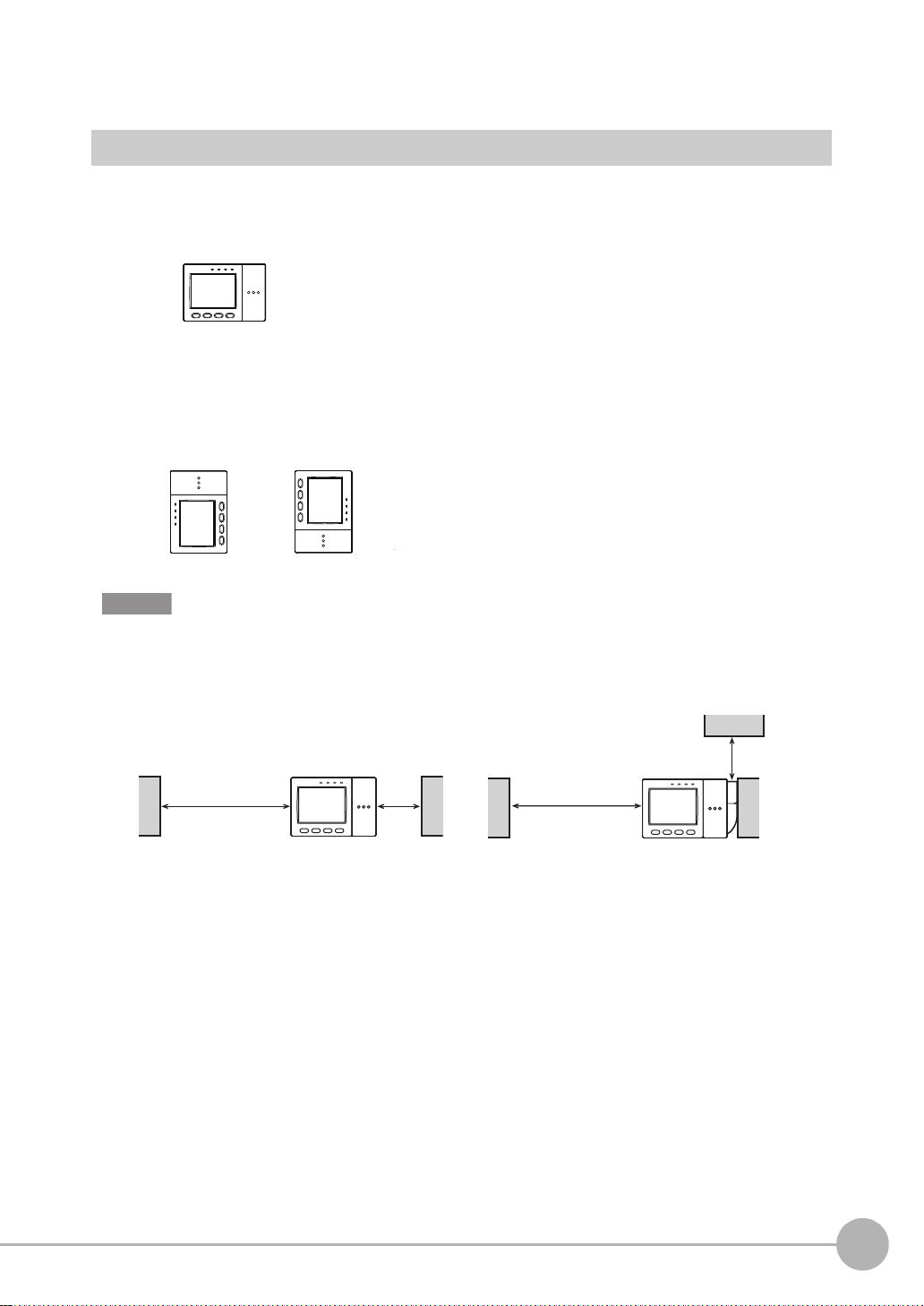
Troubleshooting
Measurement region
When setting the measurement
region (reference image)
When the measurement target
moves out of position
The position of the measurement
target is measured after the measurement region is shifted by the
amount of position shift.
Clear Images Cannot be Obtained
Measurement som etimes cannot be pe rformed successfully (e. g. measurement image is dark or contrast is
low) depending on the charact eristics of the measur ement target. Sh arp images can be o btained by appl ying
filtering, or performing cor re ct ion and adjustment to remedy the trouble.
Trouble Remedy Reference
Poor lighting The recipe method light control settings can be used . You can set the lighting
just by selecting the image that meets your specific requirements from the
thumbnails of images automatically taken under different lighting patterns.
Low contrast You can apply filters, such as "Sharpen", to the image to enhance the bound-
aries between shadow and highlight areas.
Uneven image • You can apply filters, such as "Smooth", to the image to smooth out
unevenness in the image.
• White parts of the image can be corrected to be reproduced appropriately
by adjusting the white balance.
Dark image You can raise the camera's sensitivity or lengthen the shutt er time to make the
image brighter.
p.100
p.96
p.96, p.128
p.98, p.100
Measurement Target Cannot be Measured Accurately
Due to Movement
When the measuremen t target is moving (e.g. its position or orientation are not fixed), it moves out of th e
preset measureme nt region, which prevents a ccurate measurement. The ZFX-C is provided wit h a "position
shift correction function" that corrects the position shift of mea sur em ent regions such as this befo re performing
measurement. The position shift correction function enables measurement targets whose position or
orientation is not fixed to be measured accurately.
2
BASIC OPERATIONS
Position Correction p.1 07
ZFX-C User’s Manual
Troubleshooting
43
Page 46

To Output Measurement Values to a PC or PLC
Measurement values and judgment results can be output to a personal computer, PLC or other external device.
Set the items to output and the output destination.
The following data can be output .
Output Item Output Destination
Data (measurement values)
Judgment Parallel interface
• Setting Output Content p .1 32
• Assigning the Data Output Destination p.133
Serial interface (RS-232/RS-422, USB)
Parallel interface
SD card
To Output Position Information of Measurement
Targets as Actual Coordinates
As the controller default, measurement values are output in pixel units and camera coordinates. You can
convert measurem ent results in pixels to act ual dimensions (
enabling the calibrati on function.
µm or mm) or actual coordinates for output by
Calibration p.101
44
Troubleshooting
ZFX-C User’s Manual
Page 47

SETTING THE MEASUREMENT CONDITIONS
3
Setting Measurement Items 46
Shape Inspection 46
Pattern Search 46
Graphic Search 51
Flexible Search 55
Sensitive Search 58
Size Inspection 62
Area 62
Labeling 66
Edge Inspection 70
Position 70
Width 75
Count 79
Bright/Color Inspection 82
Bright 82
HUE 84
Inspection by Individual Application 87
Grouping 87
Defect 90
Image Adjustment 94
Cameras/Lighting 98
Shutter Speed 98
Gain Setting 98
Partial Function Settings 99
Image Rate 99
Light Control (Recipe Functions) 100
Calibration 101
Registering Images 106
Position Correction 107
Additional Functions 109
Calculation 109
Setting Reflection of Individual Results 112
Logging Monitor 113
SETTING THE MEASUREMENT CONDITIONS
Page 48

Setting Measurement Items
Setup Measurement
Parts resembling the model are searched for.
Search region (region
for searching model)
Reference point
Model
(image pattern to find)
Shape Inspection
Pattern Search
Register an image pattern in beforehand as a model, and se arch for parts that most resemble an already
registered model. The correlation indicating how much parts resemble each other, the position of the
measurement target, and their angle can be output. Use this function to check for whether different-type
products are mixed in, or to ca lc ulat e t he position of the measurement targ et.
Region settings
This function sets the region to be re gi st er ed as the model and the region to searc h for the model.
X MENU mode - [Setup] - [Item] - [Region]
Item Description
Register model This function registers the image pattern to find as the model.
Setting the Region p.194
Reference model The image that is registered as the model can be referenced.
Search region Set the region in which to search for the model.
Reference point Set the coordinates of which part of the model are to be output. The default is the center
position of the model.
46
Setting Measurement Items
ZFX-C User’s Manual
Page 49

Threshold
This function sets the judgment conditions.
X MENU mode - [Setup] - [Item] - [Limits]
Setup Item Description
Correlation Sets the range of the correlation to be judged as OK.
Range: 0 to 100
Position XY Sets the range of movement in the X- and Y- axes of the measurement target to be judged
as OK.
Range: -9999.999 to 9999.999
(When calibration is OFF, the range of movement for positions X and Y are 0 to 640 and 0
to 480, respectively.)
Angle Sets the range of rotation angle to be judged as OK.
Range: -180 to 180
-
0°
+
3
SETTING THE MEASUREMENT CONDITIONS
Count
(enabled only when Verification is set to [ON])
Sets the number of search candidates to be judged as OK.
Range: 0 to 99
Image adjustment (if necessary)
The following items can be changed and set to the image of the m easurement target.
X MENU mode - [Setup] - [Item] - [Img Adj]
Item Description
Select camera
Color filter
Filtering
BGS* level
*BGS: Background Suppression
For details, see "Image Adjustment". p.94
ZFX-C User’s Manual
Setting Measurement Items
47
Page 50

Detailed settings (if necessary)
When measure m ent is not stable, adjust the det ailed conditions.
X MENU mode - [Setup] - [Item] - [Detail]
Setup Item Setting value Description
Search mode Hi-speed The search is performed at high speed.
Normal (default value) The search is performed in the normal mode for both speed
and precision.
Precision The position is calculated at high precision in sub-pixel units
(units smaller than pixels).
Rotation range 0 to 180°
(default value: 0)
Skipping angle
Interpolation OFF (default value) Calculates the angle in skipping angle units.
Verification OFF (default value) The search is performed in detail near a candidate point having
Candidate level 0 to 100
Calibration OFF (default value)
Coordinates mode Normal (default value) The position information of the input image coordinat e system
1, 2, 3, 5, 10, 15, 20, 30°
(default value: 10°)
ON
ON The search is performed in detail near all candidate points.
(default value: 60)
ON Measurement results are output using the coordinate value
Pos. correction When position shift correction is set, the position informati on is
Sets in which angle range the model (rotated in degree units) is
to be created. The smaller the skipping angle that is set, the
higher the precision becomes, however, the longer the processing time becomes.
Important
When the rotation range and skipping angle have been
changed, register the model again.
The angle is calculated as a numerical value down to three digits
past the decimal point b ased on the value obtaine d in skipping
angle units. Note, however, that the processing time increases.
This function is enabled only when the se arch mode is the nor mal mode or the precision mode.
the highest correlation value.
Select [ON] when the model cannot be searched for stably.
Sets the level at which the model is searched for during a rough
search.
Images having a correlation value at the candidate level or
more are taken to the candidate points in the Verification. Set a
lower level when the model cannot be searched for stably.
Measurement results are output using the camera's coordinate values.
converted by the calibration function.
itself is output.
output using the coordinate system corrected to the original
state when the coordinate system was registered.
Coordinates mod e p.74
48
Setting Measurement Items
ZFX-C User’s Manual
Page 51

Note
Verif ication ON
Verif ication OFF
A rough search is performed inside the search region to find the
candidate point.
A detailed search is performed at images near all
candidate points.
A detailed search is performed at images near the candidate point having
the highest correlation.
Most similar model among these model is searched for.
Registered model
-15°
-10°
-5°
Reference
5°
10°
15°
Example: When Rotation range is 15° and Skipping angle is 5°
Note
Models in the range set by Rotation range are created based on the registered model.
Verification and candidate level
+
+
+
+
+
Search Rotation Range
3
SETTING THE MEASUREMENT CONDITIONS
ZFX-C User’s Manual
Setting Measurement Items
49
Page 52

Possible output results
Reference position =position of model when
model is registered
Reference angle = angle of model when model
is registered
Measurement position =position of model found by
measurement
Measurement angle = angle of model found by
measurement
Position difference
= measurement position - reference position
Angle difference
= measurement angle -
reference angle
The following values can be output when expressions ar e set.
Item Description Message
Judgment result The judgment result is output. (0:OK, -1:NG, -2: not measured) Judge (JG)
Correlation The degree of match between the measurement image and model
image are output as a correlation value. (0 to 100)
Measurement position The X, Y coordinates of the position where the model was found are
output. (-9999.999 to 9999.999)
Measurement angle The rotation angle of the model that was found is output. (-180 to 180) Angle (TH)
Search number The number of searches that have a correlation value at the
correlation lower limit value or above is output. (0 to 99)
Reference position
Reference angle The angle when the model was registered is output. (-180 to 180) Ref. angle (ST)
Position difference The position difference obtained by "measurement position -
Angle difference The angle difference obtained by "measurement position - reference
The X, Y coordinates when the model was registered are output.
(-9999.999 to 9999.999)
reference position" is output. (-9999.999 to 9999.999)
position" is output. (-180 to 180)
Correlation (CR)
Position X, Y
(X, Y)
Search count (N)
Reference X, Y
(SX, SY)
Position dif. X, Y
(DX, DY)
Angle dif. (DT)
Note
Reference position/angle, position difference/angle difference
50
Setting Measurement Items
ZFX-C User’s Manual
Page 53

Graphic Search
Setup Measurement
Parts resembling the model are searched for stably even
in the following environments.
Search region
(region for searching
model)
Reference point
Model
Register the profile information of the image
pattern to fin d .
Lots of noise Partially clipped
Low contrast Inclined
Use this item when it is difficult to search for a model fr om p ar tia lly cl ippe d images or low-co nt ra st images. The
degree of match ind icating how much parts rese mble eac h other and the position of the meas urement object
can be output.
3
SETTING THE MEASUREMENT CONDITIONS
Note
In a pattern search, a model of the image pattern is used with priority given to contrast information. However, in a
graphic search, a model with priority given to profile information is used.
Comparison with Pattern Search
Region settings
This function sets the region to be re gi st er ed as the model and the region to searc h for the model.
X MENU mode - [Setup] - [Item] - [Region]
Item Description
Register model This function registers the image pattern to find as the model.
Reference model The image that is registered as the model can be referenced.
Search region Set the region in which to search for the model.
Reference point Set the coordinates of which part of the model are to be output. The default is the center
position of the model.
ZFX-C User’s Manual
Setting Measurement Items
51
Page 54

Note
Model registration procedure
1 Select [Auto] and enclose the area in which the profile is to be traced.
2 Select [Auto] displayed on the lower left of the screen for region settings.
The profile is traced.
3 If the profile is partially clipped, trace by [Free], [Box], [Elipse] or [Line].
Delete any noise with the [Erase] tool if noise has been traced.
Threshold
This function sets the judgment conditions.
X MENU mode - [Setup] - [Item] - [Limits]
Setup Item Description
Correlation Sets the range of the correlation to be judged as OK.
Range: 0 to 100
Position XY Sets the range of movement in the X- and Y-axes of the measurement target to be judged
as OK.
Range: -9999.999 to 9999.999
(When calibration is OFF, the range of movement for positions X and Y are 0 to 640 and 0
to 480, respectively.)
Angle Sets the range of rotation angle to be judged as OK.
Range: -180 to 180
+/- direction of angle p.47
Image adjustment (if necessary)
The following items can be changed and set to the image of the m easurement target.
X MENU mode - [Setup] - [Item] - [Img Adj]
Item Description
Select camera
Color filter
Filtering
BGS* level
For details, see "Image Adjustment". p.94
52
Setting Measurement Items
ZFX-C User’s Manual
Page 55

Detailed settings (if necessary)
When measure m ent is not stable, adjust the det ailed conditions.
X MENU mode - [Setup] - [Item] - [Detail]
Setup Item Setting value Description
Search mode Hi-speed The search is performed at high speed.
Normal (default value) The search is performed in the normal mode.
Precision The position is calculated at high precision in sub-pixel units
(units smaller than pixels).
Rotation range 0 to 180°
(default value: 0)
Skipping angle
Interpolation OFF (default value) Calculates the angle in skipping angle units.
Candidate level 0 to 100
Calibration OFF (default value)
Coordinates mode Normal (default value) The position information of the input image coordinat e system
1, 2, 3, 5, 10, 15, 20, 30°
(default value: 10°)
ON
(default value: 60)
ON Measurement results are output using the coordinate value
Pos. correction When position shift correction is set, the position informati on is
Sets in which angle range the model (rotated in degree units) is
to be created. The smaller the skipping angle that is set, the
higher the precision becomes, however, the longer the processing time becomes.
Important
When the rotation range and skipping angle have been
changed, register the model again.
The angle is calculated as a numerical value down to three digits
past the decimal point b ased on the value obtaine d in skipping
angle units. Note, however, that the processing time increases.
This function is enabled only when the se arch mode is the nor mal mode or the precision mode.
Sets the level at which the model is searched for during a rough
search.
Images having a value of the degree of match at the candidate
level or more are taken to the candidate points in the Verification. Set a lower level when the model cannot be searched for
stably.
Measurement results are output using the camera's coordinate values.
converted by the calibration function.
itself is output.
output using the coordinate system corrected to the original
state when the coordinate system was registered.
3
SETTING THE MEASUREMENT CONDITIONS
• Verification and candidate level p. 49
• Search Rotation Ra nge p.49
• Coordinates mode p.74
ZFX-C User’s Manual
Setting Measurement Items
53
Page 56

Possible output results
The following values can be output when expressions ar e set.
Item Description Message
Judgment result The judgment result is output. (0:OK, -1:NG, -2: not measured) Judge (JG)
Correlation The degree of match between the measurement image and model
image are output. (0 to 100)
Measurement position The X, Y coordinates of the position where the model was found are
output. (-9999.999 to 9999.999)
Measurement angle The rotation angle of the model that was found is output. (-180 to 180) Angle (TH)
Search number The number of searches that have a degree of match at the match
lower limit value or above is output. (0 to 99)
Reference position
Reference angle The angle when the model was registered is output. (-180 to 180) Ref. angle (ST)
Position difference The position difference obtained by "measurement position -
Angle difference The angle difference obtained by "measurement position - reference
The X, Y coordinates when the model was registered are output.
(-9999.999 to 9999.999)
reference position" is output. (-9999.999 to 9999.999)
position" is output. (-180 to 180)
Reference positio n/ angle, position difference/angle differenc e p. 50
Correlation (CR)
Position X, Y
(X, Y)
Search count (N)
Reference X, Y
(SX, SY)
Position dif. X, Y
(DX, DY)
Angle dif. (DT)
54
Setting Measurement Items
ZFX-C User’s Manual
Page 57

Flexible Search
Setup Measurement
Parts resembling one or some of the multiple registered
models are searched for, and the results of the model having the highest degree of match of all of the registered
models are acquired.
Model
(image pattern to find)
Passed product
Search region
(region for searching
model)
Use this item to detect minute differences to distinguish between passed products and same type. By
registering up to 36 image patter ns as models beforehan d, differences can be absorb ed and wasted springs
can be prevented.
The correlation indic ating how much parts resem ble each other and the position of the mea surement object
can be output.
3
SETTING THE MEASUREMENT CONDITIONS
Region settings
This function sets the region to be re gi st er ed as the model and the region to searc h for the model.
X MENU mode - [Setup] - [Item] - [Region]
Item Description
Register model This function registers the image pattern to find as the model.
Setting the Region p.194
Reference model The image that is registered as the model can be referenced.
Search region Set the region in which to search for the model.
ZFX-C User’s Manual
Setting Measurement Items
55
Page 58

Threshold
This function sets the judgment conditions.
X MENU mode - [Setup] - [Item] - [Limits]
Setup Item Description
Correlation Sets the range of the correlation to be judged as OK.
Range: 0 to 100
Position XY Sets the range of movement in the X- and Y- axes of the measurement target to be judged
as OK.
Range: -9999.999 to 9999.999
(When calibration is OFF, the range of movement for positions X and Y are 0 to 640 and 0
to 480, respectively.)
Image adjustment (if necessary)
The following items can be changed and set to the image of the m easurement target.
X MENU mode - [Setup] - [Item] - [Img Adj]
Item Description
Select camera
Color filter
Filtering
BGS level
For details, see "Image Adjustment". p.94
56
Setting Measurement Items
ZFX-C User’s Manual
Page 59

Detailed settings (if necessary)
When measure m ent is not stable, adjust the det ailed conditions.
X MENU mode - [Setup] - [Item] - [Detail]
Setup Item Setting value Description
Search mode Hi-speed The search is performed at high speed.
Normal (default value) The search is performed in the normal mode for both speed
and precision.
Precision The position is calculated at high precision in sub-pixel units
(units smaller than pixels).
Verification OFF (default value) The search is performed in detail near a candidate point having
the highest correlation value.
ON The search is performed in detail near all candidate points.
Select [ON] when the model cannot be searched for stably.
Candidate level 0 to 100
(default value: 60)
Calibration OFF (default value)
ON Measurement results are output using the coordinate value
Coordinates mode Normal (default value) The position information of the input image coordinat e system
Pos. correction When position shift correction is set, the position informati on is
Sets the level at which the model is searched for during a rough
search.
Images having a correlation value at the candidate level or
more are taken to the candidate points in the Verification. Set a
lower level when the model cannot be searched for stably.
Measurement results are output using the camera's coordinate values.
converted by the calibration function.
itself is output.
output using the coordinate system corrected to the original
state when the coordinate system was registered.
3
SETTING THE MEASUREMENT CONDITIONS
• Verification and candidate level p. 49
• Coordinates mode p.74
Possible output results
The following values can be output when expressions ar e set.
Item Description Message
Judgment result The judgment result is output. (0:OK, -1:NG, -2: not measured) Judge (JG)
Correlation The degree of match between the measurement image and model
image are output as a correlation value. (0 to 100)
Measurement position The X, Y coordinates of the position where the model was found are
output. (-9999.999 to 9999.999)
ZFX-C User’s Manual
Setting Measurement Items
Correlation (CR)
Position X, Y
(X, Y)
57
Page 60

Sensitive Search
Setup Measurement
Parts resembling the model are searched, and the degree
of match is checked in detail by subdivided models. When
subdivided models are a solid color, the solid color rate
also can be inspected.
Search region (region
for searching model)
Model
(image pattern to find)
Subdivision
Passed product
Different type Reversed
Example:
Measurement
count
In a pattern search, a difference in correlation values
does not appear, making correlation values difficult to
distinguish as there are small differences.
In a Sensitive search, even small differences
can be distinguished.
Measurement
count
Reversed Different type
Passed
product
Correlation Correlation
Threshold
< Distribution of Measurement Results >
Use this item to dete ct minute differences. Mo dels ar e autom atically s ubdivide d to chec k the deg ree of matc h
in detail. The correlatio n ind icating how much parts res emb le ea ch ot her an d the posit ion o f the m easur eme nt
target can be output. The correlation and position info rmation of the m odel having th e lowest degre e of match
of the subdivided model s i s ou tp ut .
Note
Comparison with pattern search
58
Setting Measurement Items
ZFX-C User’s Manual
Page 61

Region settings
This function sets the region to be re gi st er ed as the model and the region to searc h for the model.
X MENU mode - [Setup] - [Item] - [Region]
Item Description
Register model This function registers the image pattern to find as the model.
Setting the Region p.194
Reference model The image that is registered as the model can be referenced.
Search region Sets the region in which to search for the model.
3
Threshold
This function sets the judgment conditions.
X MENU mode - [Setup] - [Item] - [Limits]
Setup Item Description
Correlation Sets the range of the correlation to be judged as OK.
Range: 0 to 100
Position XY Sets the range of movement in the X- and Y- axes of the measurement target to be judged
as OK.
Range: -9999.999 to 9999.999
(When calibration is OFF, the range of movement for positions X and Y are 0 to 640 and 0
to 480, respectively.)
Solid color rate Sets the range of solid color to be judged as OK.
Range: 0 to 100
Angle Sets the range of rotation angle to be judged as OK.
Range: -180 to 180
+/- direction of angle p.47
Image adjustment (if necessary)
SETTING THE MEASUREMENT CONDITIONS
The following items can be changed and set to the image of the m easurement target.
X MENU mode - [Setup] - [Item] - [Img Adj]
Item Description
Select camera
Color filter
Filtering
BGS level
ZFX-C User’s Manual
For details, see "Image Adjustment". p.94
Setting Measurement Items
59
Page 62

Detailed settings (if necessary)
When measure m ent is not stable, adjust the det ailed conditions.
X MENU mode - [Setup] - [Item] - [Detail]
Setup Item Setting value Description
Search mode Hi-speed The search is performed at high speed.
Normal (default value) The search is performed in the normal mode for both speed
and precision.
Precision Matching is performed in sub-pixel units. Note, however, that
output of position information is in pixel units.
Sensitivity Low
Middle (default value)
High
Rotation range 0 to 180°
(default value: 0)
Skipping angle 1, 2, 3, 5, 6, 10, 15, 20,
30° (default value: 10°)
Interpolation OFF (default value) Calculates the angle in skipping angle units.
ON
Verification OFF (default value) The search is performed in detail near a candidate point having
ON The search is performed in detail near all candidate points.
Candidate level 0 to 100
(default value: 60)
Solid c olor check OFF (default value) Select [ON] when inspecting sections of solid color on subdi-
ON
Calibration OFF (default value)
ON Measurement results are output using the coordinate value
Coordinates mode Normal (default value) The position information of the input image coordinate system
Pos. correction When position shift correction is set, the position information is
The model is subdivided into nine models of up to three divisions in
each of the horizontal and vertical directions and then measured.
The model is subdivided into 25 models of up to five di visions in
each of the horizontal and vertical directions and then measured.
The model is subdivided into 100 models of up to ten divisions in
each of the horizontal and vertical directions and then measured.
Sets in which angle range the model (rotated in degree units) is
to be created. The smaller the skipping angle that is set, the
higher the precision becomes, however, the longer the processing time becomes.
The angle is calc u lat ed as a nu mer ic al v alu e do wn t o t hr ee dig i ts past
the decimal poi nt bas e d on th e val ue o btai n ed i n s ki p pin g an gle units.
Note, however, that the processing time increases.
This function is enabled only when the search mode is the normal
mode or the precision mode.
the highest correlation value.
Select [ON] when the model cannot be searched for stably.
Sets the level at which the model is searched for during a rough
search.
Images having a correlation value at the candidate level or
more are taken to the candidate points in the Verification. Set a
lower level when the model cannot be searched for stably.
vided models.
Measurement results are output using the camera's coordinate values.
converted by the calibration function.
itself is output.
output using the coordinate system corrected to the original
state when the coordinate system was registered.
• Verification and candidat e level p.49
• Search Rotation Ra nge p.49
• Coordinates mode p.74
60
Setting Measurement Items
ZFX-C User’s Manual
Page 63

Note
The minimum size of subdivided models is 32 x 32 pixels.
Important
When the sensitivity, rotation range, and skipping angle have been changed, register the model again.
Possible output results
The following values can be output when expressions ar e set.
Item Description Message
Judgment result The judgment result is output. (0:OK, -1:NG, -2: not measured) Judge (JG)
Correlation The degree of match between the measurement image and model
image are output as a correlation value. The correlation and position
information of the model having the lowest degree of match of the
subdivided models is output. (0 to 100)
Measurement position The X, Y coordinates of the location having the lowest correlation
value, as a result of having calculated the correlation value in detail by
subdivided models, are output. (-9999.999 to 9999.999)
Solid color rate The rate that the model is a solid color is output. The higher the solid
color rate, the higher the value increases. (0 to 100)
Measurement angle The rotation angle of the model that was found is output. (-180 to 180) Angle (TH)
Correlation (CR)
Position X, Y
(X, Y)
Solid color rate
(SC)
3
SETTING THE MEASUREMENT CONDITIONS
ZFX-C User’s Manual
Setting Measurement Items
61
Page 64

Size Inspection
Setup
Measurement
Only the picked up color is judged to be the measurement target.
Measurement region
The color of the measurement target
is picked up.
Gravity of desired color
Number of pixels of desired color = area
Angle (angle of main axis)
θ
Area
The area, gravity and angle of the desired color can be measu red. This allows you to inspect the size of th e
measurement target, and detect positions and stance.
Note
When a color camera is connected, up to four colors can be specified as the color to be measured.
When a monochrome camera is connected to the Controller, black-and-white images are binarized. White pixels are
targeted in measurement.
Image adjustment
This function picks up the color to be measured.
X MENU mode - [Setup] - [Item] - [Img Adj]
Item Description
Select camera
Color Pickup/Binary
Filtering
BGS level
(Filtering and BGS level can be used only when a monochrome camera is connected.)
For details, see "Image Adjustment". p.94
62
Setting Measurement Items
ZFX-C User’s Manual
Page 65

Region settings
-
+
This function sets the measurem ent region.
X MENU mode - [Setup] - [Item] - [Region]
Item Description
Measurement region This function sets the region to be measured.
Setting the Region p.194
Reference registration When the measurement region is set, measurement is executed on the display image,
and the result of execution is registered as the reference value. To re-register only reference values, you can use this function to re-register only referenc e values based on the
image currently on screen.
Threshold
This function sets the judgment conditions.
X MENU mode - [Setup] - [Item] - [Limits]
Setup Item Description
Area Sets the range of the area to be judged as OK.
Range: 0 to 9999999.999
(When calibration is OFF, the range becomes 0 to 307200.)
Gravity XY Sets the range of movement in the X- and Y - axes of the measurement target to be judged
as OK.
Range: -9999.999 to 9999.999
(When calibration is OFF, the range of movement for positions X and Y are 0 to 608 and 0
to 464, respectively.)
Axis angle Sets the rotating range of the measurement tar-
get to be judged as OK.
Range: -90.0 to 90.0
3
SETTING THE MEASUREMENT CONDITIONS
ZFX-C User’s Manual
Setting Measurement Items
63
Page 66

Detailed settings (if necessary)
Start point
End point
Fill profile: ON
When the measurement target color is overlaps the measurement region
Input image (Fill profile: OFF) Fill profile: ON
Pixels tha t are meas urement t arget color a re not re cognize d as the s tart po int
as pixels tha t are colors outside of measurement targ et are next scanned.
When measuring the measurement target with unevenness
Input image (Fill profile: OFF) Fill profile: ON
The measurement result changes according t o the direction in
which the measurement target is fed.
Measurement
region
When measure m ent is not stable, adjust the det ailed conditions.
X MENU mode - [Setup] - [Item] - [Detail]
Setup Item Setting value Description
Measure axis angle OFF (default value)
ON
Fill profile OFF (default value)
ON
Sets whether or not to measure the axis an gle. When [ON] is selected, the processing time increases proportionately to the time it take s to measure the axis angle.
To measure the outer periphery of the measurem en t targ et, set this item to [ON].
When this item is set to [ON], measurement is performed with all of the
area between the start point (colors outside of measurement target
measurement target color) and the end point (measurement target
→
colors outside of measurement target) inside the measurement
color
region judged to the measurement target color.
→
Calibration OFF (default value)
Coordinates mode Normal
Measurement results are output using the camera's coordinate values.
ON Measurement results are output using the coordinate value con-
verted by the calibration function.
The position information of the input image coordinate system itself
(default value)
Pos. correction When position shift correction is set, the position information is out-
is output.
put using the coordinate system corrected to the original state
when the coordinate system was registered.
Coordinates mod e p.74
64
Setting Measurement Items
ZFX-C User’s Manual
Page 67

Possible output results
The following values can be output when expressions ar e set.
Item Description Message
Judgment result The judgment result is output. (0:OK, -1:NG, -2: not measured) Judge (JG)
Area The area of the measurement target color is output.
(0 to 9999999.999)
Gravity position The X, Y coordinates of the gravity of the measurement target color
are output. (-9999.999 to 9999.999)
Axis angle The angle of the measurement target color is output.
(-90.0 to 90.0)
Reference area The area when the measurement region is set is output.
(0 to 9999999.999)
Reference position The X, Y coordinates of the gravity when the measurement region is
set are output. (-9999.999 to 9999.999)
Reference axis angle The angle when the measurement region is set is output.
(-90.0 to 90.0)
Area difference The area difference obtained by "measurement value - reference
value" is output. (-9999999.999 to 9999999.999)
Position difference The position difference obtained by "gravity position - reference
position" is output. (-9999.999 to 9999.999)
Axis angle difference The axis angle difference obtained by "measurement value -
reference value" is output. (-180.0 to 180.0)
Area (AR)
Gravity X, Y
(X, Y)
Axis angle (TH)
Ref. area (SA)
Reference X, Y
(SX, SY)
Ref. axis angle
(ST)
Area dif. (DA)
Position dif. X, Y
(DX, DY)
Axis angle dif.
(DT)
3
SETTING THE MEASUREMENT CONDITIONS
Reference positio n and Position difference p.50
ZFX-C User’s Manual
Setting Measurement Items
65
Page 68

Labeling
Setup Measurement
A group of picked up colors is detected as a label.
The color of the measurement target is picked up.
Measurement region
Label 0
Number of picked up labels: 3
Label Nos. when the area is
arranged in order of the
largest area
Label 1
Label 2
A group of colors to be measured is coun ted as a "label." Labe l Nos. are assigne d to each label after bei ng
arranged in order o f position and size. The to tal number of labels and the s ize/position of any labe l can be
output.
Note
When a color camera is connected, up to four colors can be specified as the color to be measured.
When a monochrome camera is connected to the Controller, black-and-white images are binarized. White pixels are
targeted in measurement.
Image adjustment
This function picks up the color to be measured.
X MENU mode - [Setup] - [Item] - [Img Adj]
Item Description
Select camera
Color Pickup/Binary
Filtering
BGS level
(Filtering and BGS level can be used only when a monochrome camera is connected.)
For details, see "Image Adjustment". p.94
66
Setting Measurement Items
ZFX-C User’s Manual
Page 69

Region settings
This function sets the measurem ent region.
X MENU mode - [Setup] - [Item] - [Region]
Item Description
Measurement region This function sets the region to be measured.
Setting the Region p.194
Reference registration When the measurement region is set, measurement is executed on the display image,
and the result of execution is registered as the reference value. To re-register only reference values, you can use this function to re-register only referenc e values based on the
image currently on screen.
3
Threshold
This function sets the judgment conditions.
Judgment is performe d on corresponding label Nos.
X MENU mode - [Setup] - [Item] - [Limits]
Setup Item Description
Area Sets the range of the area to be judged as OK.
Range: 0 to 9999999.999 (When calibration is OFF, the range of the area becomes 0 to
307200.)
Gravity XY Sets the range of movement in the X- and Y-axes of the measurement target to be judged
as OK.
Range: -9999.999 to 9999.999 (When calibration is OFF, the range of movement for positions X and Y are 0 to 640 and 0 to 480, respectively.)
Number of labels Sets the number of labels of the measurement target to be judged as OK.
Range: 0 to 65535
Axis angle Sets the rotating range of the measurement target to be judged as OK.
Range: -90.0 to 90.0
+/- direction of angle
Perimeter Sets the perimeter of the measurement target to be judged as OK.
Range: 0 to 9999999.999 (When calibration is OFF, the range of the perimeter becomes 0
to 200000.)
Length XY Sets the X and Y lengths of the box circumscribing the measurement target to be judged
as OK.
Range: -9999.999 to 9999.999 (When calibration is OFF, the range of movement for positions X and Y are 0 to 640 and 0 to 480, respectively.)
Roundness Sets the roundness of the measurement target to be judged as OK.
Range: 0 to 1.0
p.63
SETTING THE MEASUREMENT CONDITIONS
ZFX-C User’s Manual
Setting Measurement Items
67
Page 70

Detailed settings (if necessary)
Length Y
Length X
Measurement
target
Input image Filling up holes: ON
To calculate the
position and area
of this label
Input image O u tside trimmin g : ON
Measurement region
The region outside of the
measurement region is taken to be
the color to be measured.
Sort mode: Area descending order
When "Label No." is set to "1", the
label position and area in the center
are calculated.
When measure m ent is not stable, adjust the det ailed conditions.
X MENU mode - [Setup] - [Item] - [Detail]
Setup Item Setting value Description
Labeling mode Precision The image is measured without being compressed.
Normal (default value) The image is measured at high speed after being compressed
Sort mode Area descending order
(default value)
Area ascending order Re-assigns label Nos. in order of the smallest area.
X gravity descending order
X gravity ascending order
Y gravity descending order
Y gravity descending order
Label No. 0 to 2499 (default value: 0) Sets the label No. whose data is to be output. Note, however,
Measure axis angle OFF (default value) When set to "ON", the axis angle is calculated.
ON
Measure perimeter OFF (default value) When "ON", the following parameters are calculated:
ON
to 1/2 size in both the horizontal and vertical directions.
Re-assigns label Nos. in order of the largest area.
Re-assigns label Nos. in order of the largest X gravity coordinate.
Re-assigns label Nos. in order of the smallest X gravity coordinate.
Re-assigns label Nos. in order of the largest Y gravity coordinate.
Re-assigns label Nos. in order of the smallest Y gravity coordinate.
that the label count that can be measured d iffers according to
the Controller model.
•Length X
•Length Y
•Perimeter
Measure roundness OFF (default value) Sets whether or not to calculate roundness.
ON
Filling up holes OFF (default value) Selects how to process parts other than the target color that are
ON
Outside trimming OFF (default value) Set this function when the measurement region contains colors
ON
68
Setting Measurement Items
Roundness = (4π x area)/(perimeter x perimeter)
enclosed by the target color to be measured, such as a doughnut. When "ON" is set, parts are processed as the target color
to be measured.
other than the measurement color that are not required in measurement. When "ON" is set, the entire region outside of the
measurement region is measured as the color to be measured.
ZFX-C User’s Manual
Page 71

Setup Item Setting value Description
Area judgment 0 to 9999999.999
(default value: 0)
Calibration OFF (default value)
ON Measurement results are output using the coordinate value
Coordinates mode Normal (default value) The position information of the input image coordinate system
Pos. correction When position shift correction is set, the position information is
Sets the minimum area value to be counted as a label. Set a
larger value when noise is counted as a label by mistake.
Measurement results are output using the camera's coordinate values.
converted by the calibration function.
itself is output.
output using the coordinate system corrected to the original
state when the coordinate system was registered.
Coordinates mod e p.74
Possible output results
The following values can be output when expressions ar e set.
Item Description Message
Judgment result The judgment result is output. (0: OK, -1: NG, -2: not measured) Judge (JG)
Area The area of the corresponding label is output. (0 to 9999999.999) Area (AR)
Gravity position The X, Y coordinates of the gravity of the corresponding label are out-
Number of labels The total number of labels is output. (0 to 65535)
Axis angle The angle of the corresponding label is output. (-90.0 to 90.0) Axis angle (TH)
Perimeter
Length XY The X and Y lengths of the box circumscribing the corresponding
Roundness The roundness of the corresponding label is output. (0 to 1.0) Roundness (CL)
Reference area The area of the corresponding label when the m easurement region is
Reference position The X, Y coordinates of the gravity of the corresponding label when
Reference axis angle The angle of the corresponding label when the measurement region
Reference perimeter The perimeter of the corresponding label when the measurement
Reference length XY The X and Y lengths of the box circumscribing the corresponding
Reference roundness The roundness of the corresponding label when the measurement
Area difference The area difference obtained by "measurement value - reference
Position difference The position difference obtained by "gravity position - reference posi-
Axis angle difference The axis angle difference obtained by "measurement value - refer-
Perimeter difference The perimeter difference obtained by "measurement value - reference
Length XY difference The length difference obtained by "measurement value - reference
Roundness difference The roundnes s difference obtained by "measurement value - refer-
put. (-9999.999 to 9999.999)
The perimeter of the corresponding label is output. (0 to 9999999.999)
label are output. (0 to 9999.999)
set is output. (0 to 9999999.999)
the measurement region is set are output. (-9999.999 to 9999.999)
is set are output. (-90.0 to 90.0)
region is set is output. (0 to 9999999.999)
label when the measurement region is set are output. (0 to 9999.999)
region is set is output. (0 to 1.0)
value" is output. (-9999999.999 to 9999999.999)
tion" is output. (-9999.999 to 9999.999)
ence value" is output. (-180.0 to 180.0)
value" is output. (-9999999.999 to 9999999.999)
value" is output. (-9999.999 to 9999.999)
ence value" is output. (-1.0 to 1.0)
Gravity X, Y (X, Y)
Number of labels (N)
Perimeter (L)
Length X, Y
(LX, LY)
Ref. area (SA)
Reference X, Y
(SX, SY)
Ref. axis angle
(ST)
Ref. perimeter
(SL)
Ref. length X, Y
(SLX, SLY)
Ref. roundness
(SC)
Diff. area (DA)
Displacement X, Y
(DX, DY)
Diff. axis angle
(DT)
Diff. perimeter
(DL)
Diff. length X, Y
(DLX, DLY)
Diff. roundness
(DC)
3
SETTING THE MEASUREMENT CONDITIONS
Reference position and position difference p.50
ZFX-C User’s Manual
Setting Measurement Items
69
Page 72

Edge Inspection
Setup Measurement
The edge is searched in the region according the preset
direction and change in color.
Measurement region
Change in color: light → dark
To acquire the X coordinate of the edge
Start point End point
Start point
End point
Start point
End point
Position
This item uses the changes in brightness in a region to detect edge(s). Use this item to calculate the
coordinates of the edg e( s) of a me asurement target.
Region settings
This function sets the measurem ent region.
X MENU mode - [Setup] - [Item] - [Region]
Item Description
Measurement region This function sets the region to be measured.
Setting the Region p.194
Reference registration When the measurement region is set, measurement is executed on the display image,
and the result of execution is registered as the reference value. To re-register only reference values, you can use this function to re-register only referenc e values based on the
image currently on screen.
Note
The edge is searched from the start point towards the end point of the region.
Edge search direction
70
Setting Measurement Items
ZFX-C User’s Manual
Page 73
Threshold
This function sets the judgment conditions.
X MENU mode - [Setup] - [Item] - [Limits]
Setup Item Description
Position XY Sets the range of movement in the X- and Y- axes of the measurement target to be judged
as OK.
Range: -9999.999 to 9999.999
(When calibration is OFF, the range of movement for positions X and Y are 0 to 640 and 0
to 480, respectively.)
Image adjustment (if necessary)
The following items can be changed and set to the image of the m easurement target.
X MENU mode - [Setup] - [Item] - [Img Adj]
Item Description
Select camera
Color filter
Color Pickup/Binary
Filtering
BGS level
Which of Color filter or Color Pickup is used can be selected at [Detail] - [Color mode].
The default is use of Color filter.
For details, see "Image Adjustment". p.94
3
SETTING THE MEASUREMENT CONDITIONS
ZFX-C User’s Manual
Setting Measurement Items
71
Page 74

Detailed settings (if necessary)
When measureme nt is not stable, adjust the detailed conditions. By the a utomatic setting, the edge searc h
color is automati cal l y set.
X MENU mode - [Setup] - [Item] - [Detail]
Setup Item Setting value Description
Measurement mode Average (default value) Sets the method for calculating the position of the edge(s).
Peak
Bottom
Color mode Filter mode
(default value)
Pickup mode Specify the color to measure to find the edge of that color.
Split size 1 to 99 (default value: 1) Sets the calculation width when the peak/bottom positions are
Color Light → Dark
(default value)
Dark → Light
Edge level 0 to 100
(default value: 50)
Noise level 0 to 255
(default value: 20)
Noise width 0 to 255
(default value: 0)
Calibration OFF (default value) Measurement results are output using the camera's coordinate
ON Measurement results are output using the coordinate value
Coordinates mode Normal (default value) The position information of the input image coordinate system
Pos. correction When position shift correction is set, the position information is
Color filter processing improves the contrast of images s o that
edges are detected.
to be calculated. The peak or bottom is calculated after the
measurement region is split up by the calculation width to find
the edge(s).
Selects the density change direction of the edge(s) to be
detected.
Sets the level of density change to be judged as an edge.
Sets the level to be judged as noise.
When the difference between the minimum and maximum density values in the density region is at the noise level or lower, it
is judged that there are no edges. Set a higher value when
noise causes an edge to be detected by mistake.
Sets the width to be judged as noise.
Set a higher value when noise causes an edge to be detected
by mistake.
values.
converted by the calibration function.
itself is output.
output using the coordinate system corrected to the original
state when the coordinate system was registered.
72
Setting Measurement Items
ZFX-C User’s Manual
Page 75

Note
Average
Bottom (side near start point)
Peak (side far from start point)
Start pointEnd point
Peak/bottom width
Start pointEnd point
Measurement region
Maximum density value
Edge level
Minimum density value
100%
50%
0%
Measurement region
Maximum density value 60
Minimum density value 15
60-15>30
Measurement is performed with an edge
judged as being present.
Measurement region
Maximum density value 25
Minimum density value 10
25-10<30
Processed as "no edge." (Measurement result is NG.)
Measurement region
50%
Edge detection point
Edge level
Noise width (pixel)
Noise is judged as being present
when the density distribution is at
the edge level or lower in the
preset rang e.
Measurement mode
Sets the method for calculating the position of the
edge(s).
The side far from the start point of the measurement
region is the peak, and the side near the start point is the
bottom.
Split size
The inside of the measurement region is divided into
smaller areas to search for the edge(s), and the peak/bottom/average are calculated. This calculated width is then
set.
3
Edge level
Edges are detected as follows:
1. The density distribution of the entire measurement
region is calculated.
2. The m aximum value is taken to 100% from the minimum density value.
3. Places where the density of the edge level changes
are detected as edges.
Noise level
The minimum and maximum density values in the edge detection region are calculated, and it is judged that there
are no edges when the difference between these values is at the noise level or lower. Normally, this setting may be
left it its default value of 20. However, set a higher value when noise causes an edge to be detected by mistake.
(in region)
Maximum density value - minimum density value < noise level → Judged as "no edge" → Measurement result NG
Maximum density value - minimum density value
≥
Noise level → Judged as "edge" → Taken to be measurement target
SETTING THE MEASUREMENT CONDITIONS
Noise width
When the density distribution reaches or falls below the
edge level again within the range of the noise width from
the initial edge detection position, the detected point is
regarded as noise. Normally, this setting may be left it its
default value of 0. However, set a higher value when
noise causes an edge to be detected by mistake.
ZFX-C User’s Manual
Setting Measurement Items
73
Page 76
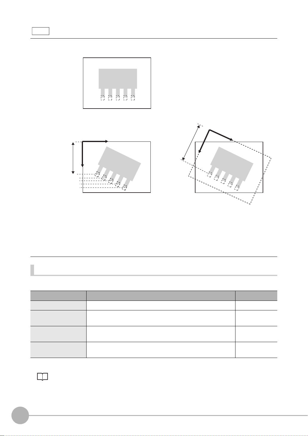
Note
Coordinates mode
Sets correction of the output coordinate system at output of the position information to ON/OFF.
Registered image
Coordinate system correction OFF
0
Input image
The position information of the
input image coordinate system
itself is output.
When position shift correction is
set, the position of the
measurement region is corrected
by the amount of calculated shift.
Coordinate system correction ON
0
When position shift correction is set,
the position information is output using
the coordinate system corrected to the
original state when the coordinate
system was registered.
In this example, edge position OK/NG
can be judged using only the Y-axis
coordinate threshold value.
Possible output results
The following values can be output when expressions ar e set.
Item Description Message
Judgment result The judgment result is output. (0:OK, -1:NG, -2: not measured) Judge (JG)
Edge position The X, Y coordinates of the edge position are output.
(-9999.999 to 9999.999)
Reference position The X, Y coordinates of the edge position when the measurement
region is set are output. (-9999.999 to 9999.999)
Position difference The difference obtained by "measurement position - reference
position" is output. (-9999.999 to 9999.999)
Position X, Y
(X, Y)
Reference X, Y
(SX, SY)
Position dif. X, Y
(DX, DY)
For details on reference po sit io n, position difference p.50
74
Setting Measurement Items
ZFX-C User’s Manual
Page 77

Width
Setup Measurement
Two edges are searched in the region.
Edge 1 is searched from the start point towards the end
point. Edge 2 is searched from the end point towards the
start point.
Measurement region
Start
point
Dimension
End
point
Edge 1
(start point side)
Edge 2
(end point side)
This item uses the changes in brightness in a region to detect edge(s). Two edges are found in a single
measurement region, and the distance between these edges is output as a dimension.
Region settings
This function sets the measurem ent region.
3
SETTING THE MEASUREMENT CONDITIONS
X MENU mode - [Setup] - [Item] - [Region]
Item Description
Measurement region This function sets the region to be measured.
Setting the Region p.194
Reference registration
When the measurement region is set, measurement is executed on the display image, and the result
of execution is r egi ster ed as the refe rence value . To re-register only refe rence v alues , you ca n use
this function to re-register only reference values based on the image currently on screen.
Threshold
This function sets the judgment conditions.
X MENU mode - [Setup] - [Item] - [Limits]
Setup Item Description
Width Sets the range of the edge width to be judged as OK.
Range: 0 to 9999.999
(When calibration is OFF, the range becomes 0 to 800.)
Position X1, Y1
Position X2, Y2
ZFX-C User’s Manual
Sets the range of movement in the X- and Y- axes to be judged as OK.
Range: -9999.999 to 9999.999
(When calibration is OFF, the range of movement for positions X and Y are 0 to 640 and 0
to 480, respectively.)
Setting Measurement Items
75
Page 78

Image adjustment (if necessary)
The following items can be changed and set to the image of the m easurement target.
X MENU mode - [Setup] - [Item] - [Img Adj]
Item Description
Select camera
Color filter
Color Pickup/Binary
Filtering
BGS level
Which of Color filter or Color Pickup is used can be selected at [Detail] - [Color mode]. The
default is use of Color filter.
For details, see "Image Adjustment". p.94
Detailed settings (if necessary)
When measureme nt is not stable, adjust the detailed conditions. By the a utomatic setting, the edge searc h
color is automati cal l y set.
X MENU mode - [Setup] - [Item] - [Detail]
Setup Item Setting value Description
Measurement mode Average (default value) Sets the method for calculating the edge width.
Maximum
Minimum
Color mode Filter mode
(default value)
Pickup mode Specify the color to measure to find the edge of that color.
Split size 1 to 99 (default value: 1)
Color 1/2
Edge level 1/2 0 to 100
Noise level 1/2 0 to 255
Noise width 1/2 0 to 255
Calibration OFF (default value)
Light → Dark (default value
Dark → Light
(default value: 50)
(default value: 20)
(default value: 0)
ON Measurement results are output using the coordinate value
Color filter processing improves the contrast of images s o that
edges are detected.
Sets the calculation width when the Maximum/Minimum widths are
to be calculated. The Maximum or Minimum is calculated after the
measurement region is split up by the c alculation width to find the
edge(s).
) Selects the density change direction of the edge(s) to be
detected.
Sets the level of density change to be judged as an edge.
Sets the level to be judged as noise.
When the difference between the minimum and maximum density values in the density region is at the noise level or lower, it
is judged that there are no edges. Set a higher value when
noise causes an edge to be detected by mistake.
Sets the width to be judged as noise.
Set a higher value when noise causes an edge to be detected
by mistake.
Measurement results are output using the camera's coordinate values.
converted by the calibration function.
76
Setting Measurement Items
ZFX-C User’s Manual
Page 79

Setup Item Setting value Description
Coordinates mode Normal (default value) The position information of the input image coordinate system
itself is output.
Pos. correction When position shift correction is set, the position information is
output using the coordinate system corrected to the original
state when the coordinate system was registered.
• Split size, Edge level, Noise level, N oise width p.73
• Coordinates mode p.74
Note
Measurement mode
When Maximum and Minimum are selected, the measurement region is split up into small regions by Split size to
calculate the edge width. The maximum value or the minimum value is output. W hen Average is selected , the ave rage of the entire measurement region is calculated.
Width when [Maximum] is selected
Split size
Start point End point
3
SETTING THE MEASUREMENT CONDITIONS
Width when [Minimum] is selected
ZFX-C User’s Manual
Setting Measurement Items
77
Page 80

Possible output results
The following values can be output when expressions ar e set.
Item Description Message
Judgment result The judgment result is output. (0:OK, -1:NG, -2: not measured) Judge (JG)
Edge width The measured edge width is output. (0 to 9999.999) Width (WD)
Edge position 1/2 T he X, Y coordinates of the edge position are output.
(-9999.999 to 9999.999)
Important
The start point side of the regi on become s
Position
end point side becomes
Reference edge width The edge width when the measurement region is set is output.
(0 to 9999.999)
Reference edge position
1/2
Width difference The width difference obtained by "measurement value - reference
Position difference 1/2 The difference obtained by "measurement position - reference
The X, Y coordinates of the edge position when the measurement
region is set are output. (-9999.999 to 9999.999)
value" is output. (-9999.999 to 9999.999)
position" is output. (-9999.999 to 9999.999)
X2/Y2.
Position
X1/Y1, and the
Position Difference p.50
Position
X1, Y1, X2, Y2
(X1, Y1, X2, Y2)
Reference width (SW)
Reference
X1, Y1, X2, Y2
(SX1, SY1, SX2, SY2)
Width dif. (DW)
Position dif.
X1, Y1, X2, Y2
(DX1, DY1, DX2, DY2)
78
Setting Measurement Items
ZFX-C User’s Manual
Page 81

Count
Setup Measurement
Measurement region
Target color: dark
Width
Number of edges
Pitch (distance between mid points)
This item uses the changes in brightness in a region to detec t ed ge( s) . Thi s i te m find s th e edges of a specified
color (dark/light) in a singl e m easurement region, and outpu ts the nu mber, width and pitch of the edges.
Region settings
This function sets the measurem ent region.
X MENU mode - [Setup] - [Item] - [Region]
Item Description
Measurement region This function sets the region to be measured.
3
SETTING THE MEASUREMENT CONDITIONS
Setting the Region p.194
Reference registration When the measurement region is set, measurement is executed on the display image,
and the result of execution is registered as the reference value. To re-register only reference values, you can use this function to re-register only referenc e values based on the
image currently on screen.
Threshold
This function sets the judgment conditions.
X MENU mode - [Setup] - [Item] - [Limits]
Setup Item Description
Number of edges Sets the range of the number of edges to be judged as OK.
Average pitch Sets the range of the edge pitch to be judged as OK.
Average width Sets the range of the edge width to be judged as OK.
Range: 0 to 255
Range: 0 to 9999.999
(When calibration is OFF, the range becomes 0 to 640.)
Range: 0 to 9999.999
(When calibration is OFF, the range becomes 0 to 640.)
ZFX-C User’s Manual
Setting Measurement Items
79
Page 82

Image adjustment (if necessary)
The following items can be changed and set to the image of the m easurement target.
X MENU mode - [Setup] - [Item] - [Img Adj]
Item Description
Select camera
Color filter
Color Pickup/Binary
Filtering
BGS level
Which of Color filter or Color Pickup is used can be selected at [Detail] - [Color mode]. The
default is use of Color filter.
For details, see "Image Adjustment". p.94
Detailed settings (if necessary)
When measure m ent is not stable, adjust the det ailed conditions.
X MENU mode - [Setup] - [Item] - [Detail]
Setup Item Setting value Description
Measurement mode Normal (default value) Selects this item in the case of measurement targets whose pin
width and pitch are at least two pixels.
Fine Selects this item to stably measure widths narrow er than nor-
mal and the number of gaps.
Color mode Filter mode
(default value)
Pickup mode Specify the color to measure to find the edge of that color.
Target color Light (default value) Selects the target color to be counted as the number of edges.
Dark
Edge level 0 to 100
(default value: 50)
Noise level 0 to 255
(default value: 20)
Noise width 0 to 255
(default value: 0)
Calibration OFF (default value)
ON Measurement results are output using the coordinate value
Color filter processing improves the contrast of images s o that
edges are detected.
When a color camera is in use, the picked-up color is targeted
for counting when this setting is set to [Light].
Sets the level of density change to be judged as an edge.
Sets the level to be judged as noise.
When the difference between the minimum and maximum density values in the density region is at the noise level or lower, it
is judged that there are no edges. Set a higher value when
noise causes an edge to be detected by mistake.
Sets the width to be judged as noise.
Set a higher value when noise causes an edge to be detected
by mistake.
Measurement results are output using the camera's coordinate values.
converted by the calibration function.
Noise level, Noise width p.73
80
Setting Measurement Items
ZFX-C User’s Manual
Page 83

Note
Measurement region
Max. density difference
value
Edge level
Min. density difference
value
100%
50%
0%
Edge level
With the count function, the edge is detected by derivative distribution.
1. The amount of change in directions light→dark and
dark→light is calculated.
2. The place where the amount of change exceeds the
edge level is detected as the edge.
Possible output results
The following values can be output when expressions ar e set.
Item Description Message
Judgment result The judgment result is output. (0:OK, -1:NG, -2: not measured) Judge (JG)
Number of edges The number of detected edges is output. (0 to 255)
Average pitch The average detected pitch is output. (0 to 9999.999) Average pitch (P)
Minimum pitch The minimum detected pitch is output. (0 to 9999.999) Min. pitch (PL)
Maximum pitch The maximum detected pitch is output. (0 to 9999.999) Max. pitch (PH)
Average width T he average detected edge width is output. (0 to 9999.999) Average width (W)
Minimum width The minimum detected edge width is output. (0 to 9999.999) Min. width (WL)
Maximum width The maximum detected edge width is output. (0 to 9999.999) Max. width (WH)
Number of edges (N)
3
SETTING THE MEASUREMENT CONDITIONS
ZFX-C User’s Manual
Setting Measurement Items
81
Page 84

Bright/Color Inspection
Setup Measurement
Measurement region Density average,
density deviation
Bright
Use this item to m easure the br ightness of me asurement targets. Th e density av erage and de nsity deviation
(brightness fluctuat ions) are output. Change in brigh tness can be used to inspect w hether or not parts are
present.
Region settings
This function sets the measurem ent region.
X MENU mode - [Setup] - [Item] - [Region]
Setup Item Description
Measurement region This function sets the region to be measured.
Setting the Region p.194
Reference registration When the measurement region is set, measurement is executed on the display image,
and the result of execution is registered as the reference value. To re-register only reference values, you can use this function to re-register only referenc e values based on the
image currently on screen.
Threshold
This function sets the judgment conditions.
X MENU mode - [Setup] - [Item] - [Limits]
Setup Item Description
Density average Sets the range of the density average to be judged as OK.
Range: 0 to 255.0
Density deviation Sets the range of the density deviation to be judged as OK.
Range: 0 to 127.0
82
Setting Measurement Items
ZFX-C User’s Manual
Page 85

Image adjustment (if necessary)
The following items can be changed and set to the image of the m easurement target.
X MENU mode - [Setup] - [Item] - [Img Adj]
Item Description
Select camera
Color filter
Filtering
BGS level
For details, see "Image Adjustment". p.94
Possible output results
The following values can be output when expressions ar e set.
Item Description Message
Judgment result The judgment result is output. (0:OK, -1:NG, -2: not measured) Judge (JG)
Density average The average of the density inside the measurement region is out-
put. (0 to 255.0)
Density deviation The brightness fluctuations in the measurement region are output.
(0 to 127.0)
Reference density average
Reference density
deviation
Density average
difference
Density deviation
difference
The density average when the measurement region is set is output.
(0 to 255.0)
The density deviation when the measurement region is set is output. (0 to 127.0)
The difference obtained by "measurement value - reference value"
is output. (0 to 255.0)
The difference obtained by "measurement value - reference value"
is output. (0 to 127.0)
Density average (AV)
Density deviation (DV)
Ref. average (SA)
Ref. deviation (SD)
Average dif. (DA)
Deviation dif. (DD)
3
SETTING THE MEASUREMENT CONDITIONS
ZFX-C User’s Manual
Setting Measurement Items
83
Page 86

HUE
Setup Measurement
Measurement region Hue, saturation,
brightness value
Use this item to m easu re t he color o f meas urem ent targets. Thi s item can be used to m easu re wh ether o r not
different-colored products are mixed in, for example. Average hue, saturation and brightness value, and
respective deviations (fluctuations) can be output.
Important
This function cannot be used when a monochrome camera is connected.
Region settings
This function sets the measurem ent region.
X MENU mode - [Setup] - [Item] - [Region]
Setup Item Description
Measurement region This function sets the region to be measured.
Setting the Region p.194
Reference registration When the measurement region is set, measurement is executed on the display image,
and the result of execution is registered as the reference value. To re-register only reference values, you can use this function to re-register only referenc e values based on the
image currently on screen.
84
Setting Measurement Items
ZFX-C User’s Manual
Page 87

Threshold
This function sets the judgment conditions.
Note
• The color can be distinguished more precisely as threshold values can be set to each of hue, saturation and
value. Alternatively, if you set wide allowable saturation and value ranges, color can be distinguished more stably
by hue without being influenced by fluctuating lighting conditions.
X MENU mode - [Setup] - [Item] - [Limits]
Setup Item Description
Hue average Sets the range of hues to be judged as OK.
Range: 0 to 360.0
Saturation average Sets the range of saturations to be judged as OK.
Range: 0 to 100.0
Value average Sets the range of values to be judged as OK.
Range: 0 to 100.0
Hue deviation Sets the range of hue fluctuation to be judged as OK.
Range: 0 to 180.0
Saturation deviation Sets the range of saturation fluctuation to be judged as OK.
Range: 0 to 50.0
Value deviation Sets the range of value fluctuation to be judged as OK.
Range: 0 to 50.0
3
SETTING THE MEASUREMENT CONDITIONS
Image adjustment (if necessary)
The following items can be changed and set to the image of the m easurement target.
X MENU mode - [Setup] - [Item] - [Img Adj]
Item Description
Select camera Selects the camera to be used by this item.
Detailed settings (if necessary)
When measure m ent is not stable, adjust the det ailed conditions.
X MENU mode - [Setup] - [Item] - [Detail]
Setup Item Setting value Description
Deviation O FF Selects whether or not the deviation values of hue, saturation
ON (default value)
and value are to be calculated.
ZFX-C User’s Manual
Setting Measurement Items
85
Page 88

Possible output results
The following values can be output when expressions ar e set.
Item Description Message
Judgment result The judgment result is output. (0:OK, -1:NG, -2: not measured) Judge (JG)
Hue The hue average is output. (0 to 360.0) H average (H)
Saturation T he satura tion average is output. (0 to 100.0) S average (S)
Value The value average is output. (0 to 100.0) V average (V)
Hue deviation The hue fluctuation is output. (0 to 180.0) H deviation (HD)
Saturation deviation The saturation fluctuation is output. (0 to 50.0) S deviation (SD)
Value deviation The value fluctuation is output. (0 to 50.0) V deviation (VD)
Reference hue The hue when the measurement region is set is output.
(0 to 360.0)
Reference saturation
Reference value The value when the measurement region is set is output.
Hue difference The hue difference obtained by "measurement value - reference
Saturation difference The saturation difference obtained by "measurement value -
Value dif ference The value difference obtained by "measurement value - reference
Reference hue deviation The hue fluctuation when the measurement region is set is
Reference saturation
deviation
Reference value
deviation
Hue deviation difference The hue deviation difference obtained by "measurement value -
Saturation deviation
difference
Value deviation
difference
Hue maximum/minimum The hue maximum/minimum values are output. (0 to 360.0) Max. H/Min. H
Saturation maximum/
minimum
Value maximum/minimum
The saturation when the measurement region is set is output.
(0 to 100.0)
(0 to 100.0)
value" is output. (-360.0 to 360.0)
reference value" is output. (-100.0 to 100.0)
value" is output. (-100.0 to 100.0)
output. (0 to 180.0)
The saturation fluctuation when the measurement region is set is
output. (0 to 50.0)
The value fluctuation when the measurement region is set is
output. (0 to 50.0)
reference value" is output. (-180.0 to 180.0)
The saturation deviation difference obtained by "measurement
value - reference value" is output. (-50.0 to 50.0)
The value deviation difference obtained by "measurement value -
reference value" is output. (-50.0 to 50.0)
The saturation maximum/minimum values are output. (0 to 100.0) Max. S/Min. S
The value maximum/minimum values are output. (0 to 100.0) Max. V/Min. V
Ref. H average (SH)
Ref. S
average
Ref. V average (SV)
H average dif. (DH)
S average dif. (DS)
V average dif. (DV)
Ref. H deviation (SHD)
Ref. S deviation (SSD)
Ref. V deviation (SVD)
H deviation dif. (DH)
S deviation dif. (DSD)
V deviation dif. (DVD)
(HH, LH)
(HS, LS)
(HV, LV)
(SS)
Nos. indicating hue , sat uration and value p.206
86
Setting Measurement Items
ZFX-C User’s Manual
Page 89

Inspection by Individual Application
Register to 0. Register to 1. Register to 2.
Setup
Search region
(region for searching model)
Measurement
The index No. of the most similar model is output.
Grouping
Use this item to group products, fo r example, on lines wh ere many types of prod ucts are conveyed. Regist er
the image pattern to be used as the reference for grouping produ cts as a model beforeha nd. Up to 64 models
can be registered. The No. of the model that resembles the input image the most, the correlation indicating how
much parts resemble each oth er and t he position of the measurement object can be output.
3
Index
(0 to 63)
0
1
2
63
Note
With the grouping function, automatic setting of the number of defects is not executed even in screens with the
[AUTO] button.
Model
(register up to 4)
Region settings
This function sets the region to be re gi st er ed as the model and the region to searc h for the model.
X MENU mode - [Setup] - [Item] - [Region]
Item Description
Register model This function registers the image pattern to find as the model.
SETTING THE MEASUREMENT CONDITIONS
Setting the Region p.194
Reference model The image that is registered as the model can be referenced.
Search region Set the region in which to search for the model.
ZFX-C User’s Manual
Setting Measurement Items
87
Page 90

Threshold
This function sets the judgment conditions.
X MENU mode - [Setup] - [Item] - [Limits]
Setup Item Description
Correlation Sets the range of the correlation to be judged as OK.
Range: 0 to 100
Position XY Sets the range of movement in the X- and Y- axes of the measurement target to be judged
as OK.
Range: -9999.999 to 9999.999
(When calibration is OFF, the range of movement for positions X and Y are 0 to 640 and 0
to 480, respectively.)
Index No. Sets the range of index Nos. to be judged as OK.
Range: 0 to 63
Image adjustment (if necessary)
The following items can be changed and set to the image of the m easurement target.
X MENU mode - [Setup] - [Item] - [Img Adj]
Item Description
Select camera
Color filter
Filtering
BGS* level
For details, see "Image Adjustment". p.94
88
Setting Measurement Items
ZFX-C User’s Manual
Page 91

Detailed settings (if necessary)
When measure m ent is not stable, adjust the det ailed conditions.
X MENU mode - [Setup] - [Item] - [Detail]
Setup Item Setting value Description
Search mode Hi-speed The search is performed at high speed.
Normal (default value) The search is performed in the normal mode for both speed
and precision.
Precision The position is calculated at high precision in sub-pixel units
(units smaller than pixels).
Verification OFF (default value) The search is performed in detail near a candidate point having
the highest correlation value.
ON The search is performed in detail near all candidate points.
Select [ON] when the model cannot be searched for stably.
Candidate level 0 to 100
(default value: 60)
Calibration OFF (default value)
ON Measurement results are output using the coordinate value
Coordinates mode Normal (default value) The position information of the input image coordinat e system
Pos. correction When position shift correction is set, the position informati on is
Sets the level at which the model is searched for during a rough
search.
Images having a correlation value at the candidate level or
more are taken to the candidate points in the Verification. Set a
lower level when the model cannot be searched for stably.
Measurement results are output using the camera's coordinate values.
converted by the calibration function.
itself is output.
output using the coordinate system corrected to the original
state when the coordinate system was registered.
3
SETTING THE MEASUREMENT CONDITIONS
• Verification and candidate level p. 49
• Coordinates mode p.74
Possible output results
The following values can be output when expressions ar e set.
Item Description Message
Judgment result The judgment result is output. (0:OK, -1:NG, -2: not measured) Judge (JG)
Correlation The degree of match between the measurement image and model
image are output as a correlation value. (0 to 100)
Measurement position The X, Y coordinates of the position where the model was found are
output. (-9999.999 to 9999.999)
Index No. Outputs the No. of the model having the highest correlation. (0 to 63) Index No. (IN)
ZFX-C User’s Manual
Setting Measurement Items
Correlation (CR)
Position X, Y
(X, Y)
89
Page 92

Defect
Setup
Measurement
The measurement region is automatically subdivided into
smaller sections to detect for changes in their respective
brightness (density). The density difference with the surrounding area is collected, parts having a large difference are
judged to be a defect, and the position information and extent
of the defects of the locations having the highest number of
defects are output.
Measurement region
Subdivision
Scratch
Chipping and burrs on the outer periphery also can be detected.
Burr
Chipping
The extent of the defects is calculated in subdivided
regions, and regions at or exceeding the defect
threshold are output as the number of defects.
Use this item to detect dirt, scrat ching, chipping, burrs, and other defects on plain measuremen t targets. The
extent of the defects at loc ations having the highest numb er of defects and their positions are o utput. The
number of locations where the extent of defects equals or exceeds the noise level also are output.
Note
90
Setting Measurement Items
Number of Defects
ZFX-C User’s Manual
Page 93

Region settings
Measurement Region
Measurement
region
Measurement region
Set the measurement region.
X MENU mode - [Setup] - [Item] - [Region]
Item Description
Measurement Region This function sets the region to be measured.
Setting the Region p.194
Inspection is classified into the following four inspections for each region setup.
•Line
Select this item to inspect measurement targets for chipping, burrs and other defects.
The shape that can be drawn is one straight line.
• Circum/Arc
Select this item to inspect round measurement targets for chipping, burrs and other
defects. The shape that can be drawn is one circumference or arc.
3
SETTING THE MEASUREMENT CONDITIONS
•Area
Select this item to inspect the entire measurement target for scratches and dirt. A combination of up to five shapes (rectangles, ellipses, circles, polygons).
Reference registration When the measurement region is set, measurement is executed on the display image,
and the result of execution is registered as the reference value. To re-register only reference values, you can use this function to re-register only referenc e values based on the
image currently on screen.
Threshold
This function sets the judgment conditions.
X MENU mode - [Setup] - [Item] - [Limits]
Setup Item Description
Defect Sets the defect judgment value to be judged as OK.
Range: 0 to 255
Density Sets the density range to be judged as OK.
Range: 0 to 255
Number of defects Sets the range of number of defects to be judged as OK.
ZFX-C User’s Manual
Range: 0 to 255
Setting Measurement Items
91
Page 94
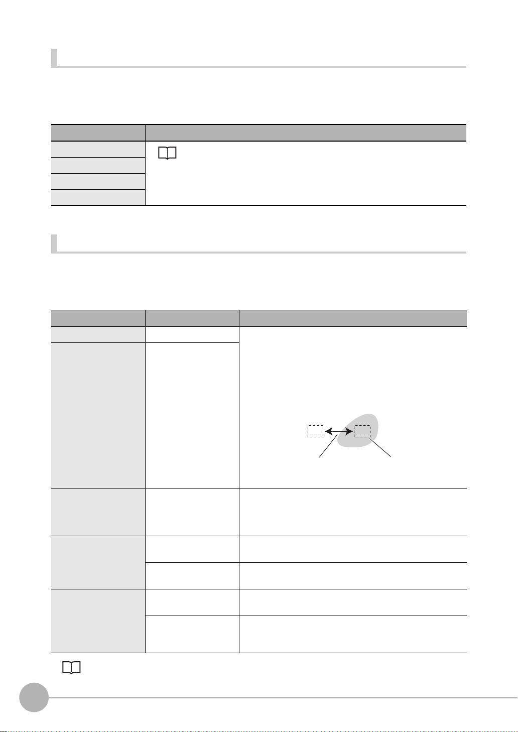
Image adjustment (if necessary)
Detection interval Detection area corresponding
to detection size
The following items can be changed and set to the image of the m easurement target.
X MENU mode - [Setup] - [Item] - [Img Adj]
Item Description
Select camera
Color filter
Filtering
BGS level
For details, see "Image Adjustment". p.94
Detailed settings (if necessary)
When measure m ent is not stable, adjust the det ailed conditions.
X MENU mode - [Setup] - [Item] - [Detail]
Setup Item Setting value Description
Detection size 4 to 64 (default value: 8) Creates a small detection area corresponding to the detection
Detection interval 4 to 64 (default value: 8)
size inside the measurement region.
The average density is calculated for each detection area. The
average density of the detection area is then compared with the
surrounding average density, and the defect position is
detected by how much the average density differs with the surrounding area. The difference with the average density that
was the largest is output as the defect value.
Noise level
Calibration OFF (default value) Measurement results are output using the camera's coordinate
Coordinates mode Normal (default value) The position information of the input image coordinate system
0 to 255 (default value: 60)
ON Measurement results are output using the coordinate value
Pos. correction When position shift correction is set, the position information is
Coordinates mod e p.74
92
Setting Measurement Items
Places having a defect value lower than the noise level are
removed as the noise component, while places having a defect
value higher than the noise level are counted as defect positions.
values.
converted by the calibration function.
itself is output.
output using the coordinate system corrected to the original
state when the coordinate system was registered.
ZFX-C User’s Manual
Page 95

Note
Detection size
Defect
Sensitivity
Processing time
Stronger
Weaker
Longer
Shorter
Guidelines for setting detection size and detection interval
• Detection size
Determine the detection size roughly according to the size of the defect to be detected.
Setting a smaller detection size results in stronger detection sensitivity, while setting a larger detection size results
in weaker detection sensitivity.
(1) (2)
When a larger detection size is set, the difference with elements that are not defects decreases as the density of
elements other than defects also is included in the calculation at (2). In other words, the more background that is
included in the detection area, the weaker the detection sensitivity becomes.
• Detection interval
Determine the detection interval roughly according to the size of the defect and the detection size.
The larger the detection interval that is set, the shorter the processing time becomes.
When the detection area is greater than the defect, set a smaller detection interval.
When the defect is greater than the detection area, set a slightly larger detection interval.
When a small detection interval is set, elements overlapping the edge of the defect also are included in the comparison, and so the defect value decreases, which results in less stable detection of the defect.
3
SETTING THE MEASUREMENT CONDITIONS
Possible output results
The following values can be output when expressions ar e set.
Item Description Message
Judgment result The judgment result is output. (0:OK, -1:NG, -2: not measured) Judge (JG)
Defect Measured extent of defects is output. (0 to 255) Defect (F)
Maximum density The maximum density value inside the measurement region is output.
Minimum density The minimum density value inside the measurement region is output.
Number of defects The number of defects having an extent of defects at or exceeding the
Defect position The X, Y coordinates of the defect position are output.
Reference position The X, Y coordinates of the defect position when the measurement
Position difference The difference obtained by "measurement position - reference
For details on reference po sit io n, position difference p.50
ZFX-C User’s Manual
(0 to 255)
(0 to 255)
judgment condition is output. (0 to 255)
(-9999.999 to 9999.999)
region is drawn are output. (-9999.999 to 9999.999)
position" is output. (-9999.999 to 9999.999)
Setting Measurement Items
Max. density (GH)
Min. density (GL)
Number of defects
(N)
Position X, Y
(X, Y)
Reference X, Y
(SX, SY)
Position dif. X, Y
(DX, DY)
93
Page 96

Image Adjustment
This section describes the functio ns for app ly filters, etc . to proces s images c aptured from the cam era so that
they can be easi er-to-measure. Item s that can be set differ according to the measurement item and type of
camera. Only availabl e i te m s ar e di splayed.
Select Camera
Select camera 0 or camer a 1 as the camera to be used in this meas ur em ent item.
X MENU mode - [Setup] - [Item] - [Img Adj]-[Select camera]
Color Filter
The contrast of images ca n be imp roved by passi ng imag es thr ough c olor filters . This f unct ion can be set on ly
when a color camera is connected to the Controller. When a color filter setting is changed, a new image
processed by the color filter is displayed on the right side of the monitor. Set the color filter while monitoring the
image on screen.
Note
When AUTO is set for measurement items that support use of color filters, the optimum color filter is automatically
set.
AUTO Setting p.168
Color Filter p.202
X MENU mode - [Setup] - [Item] - [Img Adj] - [Select camera] - [Color filter]
Item Description
Select filter The color filter can be selected as desired. (Red, Blue, Green, Yellow, Cyan, Magenta,
Gray, Custom)
When [Custom filter] is selected, any color in the color bar can be set to the filter.
Auto function Sets whether or not to perform automatic selection of color filter processing when the
automatic setting is executed.
On: The current image is analyzed to automatically select the optimum color filter each
time that the automatic setting is executed.
Off: The currently selected color filter is fixed, and is not cleared and held even if the
automatic setting is executed.
94
Setting Measurement Items
ZFX-C User’s Manual
Page 97

Color Pickup/Binary
This function picks up the color to be measured.
When a color camera is connected to the Controller
X MENU mode - [Setup] - [Item] - [Img Adj] - [Select camera] - [Color Pickup]
Item Description
Region When an area containing a color to be measured is specified, and [AUTO] is selected, up
to four colors are automatically picked up in order of the color having the largest area.
Pickup Color If the appropriate image is not o btained by automatic color pick up, the t hree parameters
hue, saturation and brightness can be fine-adjusted for each candidate color.
When [Auto function] is set to [OFF], the color pick up is not updated when the automatic
setting is next executed.
T o exclude a specific color from the measurement target, set [Enable/Disable] to [Disable].
Color Pickup, p.204
When a monochrome camera is connected to the Controller
X MENU mode - [Setup] - [Item] - [Img Adj] - [Select camera] - [Binary]
Item Description
Binary level S ets the level fo r conv erting cont one images m ade up of 256 tones capt ured f rom a cam-
era to binarized images. As white pixels are targeted in measurement, the binary level is
adjusted so that the measurement target is transformed into white pixels.
Reverse Reverses the black and white of binary images.
After the image is inverted, the area converted to white pixels is the measurement target.
3
SETTING THE MEASUREMENT CONDITIONS
ZFX-C User’s Manual
Setting Measurement Items
95
Page 98

Pre-processing
This function processes images captured from the camera so that they can be easier-to-measure. Eight
filtering options are avai lable so that you can set filtering differen t for each of position correction and ac tual
measurement.
When you move the c ur sor, a filtered image of the image at the cursor p osi ti on i s displayed on the right side of
the monitor. Set the filter while monitoring the im age on screen.
X MENU mode - [Setup] - [Item] - [Img Adj] - [Select camera] - [Filtering]
Filtering Target Ima ge Description of Filtering
OFF (default value) - Smooth Measurement targets con-
taining slightly unevenness
Erosion Black measurement targets
containing white noise
Dilation White measurement tar-
gets containing black noise
Median Measurement targets con-
taining slightly unevenness
Sharpen Measurement targets con-
taining fuzzy areas
(fluctuating lighting, etc.)
V Edge Images that are difficult to
pick up due to poor contrast
H Edge Images that are difficult to
pick up due to poor contrast
All Edge Images that are difficult to
pick up due to poor contrast
Creates a cloudy effect to soften the unevenness.
Reduces the white component to eliminate the noise.
Spreads the white component to eliminate the black noise.
Softens the unevenness while keeping the image contour
intact.
Enhances the border lines between light and dark areas in
the image.
Picks up the vertical border lines (contrast) in the image.
Picks up the horizontal border lines (contrast) in the image.
Picks up all border lines (contrast) in the image.
Note
The filter strength can be selected when applying the filtering options to images. Each selection of t he [5x5 filter]/
[3x3 filter] in the filtering setup screen toggles the filter strength.
96
Setting Measurement Items
Filter Strength
ZFX-C User’s Manual
Page 99

Background Suppression
BGS level0.Pattern
L[ 060] H[ 200]
Image before background is removed
Measurement target density
Image with background removed
Background
density
Upper limit value: 220
Lower limit value: 100
2550
• All parts of the image having a density of 100
or less are not treated as the measurement
target and are converted to 0.
• Only parts of the image within the density value range of 100 to 220 are treated as the
measurement target and are extended to
tones within the range 0 to 255.
This function removes unwanted backg round from the im ages to exclude them from the m easurement target.
Setting the BGS leve l converts images at the lower limit value or b elow to den sity 0 and ima ges at the up per
limit or above to density 255 so that only an image of density within the range lower limit value to upper limit
value is ext ended and turned i nto a measurement target havin g 0 t o 255 tones. When you m ove the cursor, an
image of the image at the cursor position is displayed at the cursor position with unwanted background
removed. Set the BGS level whi l e m onit or i ng t he im age on screen.
Example: Set the lower limit val ue to 100 and upper limit value to 220
3
SETTING THE MEASUREMENT CONDITIONS
X MENU mode - [Setup] - [Item] - [Img Adj] - [Select camera] - [BGS level]
ZFX-C User’s Manual
Setting Measurement Items
97
Page 100

Cameras/Lighting
Set the camera and light ing ope ra ting c ondi tions for cap turing image s a nd m easur ing mea sureme nt targets in
an optimum state.
Shutter Speed
Set the shutter speed to match the speed of m ovement of the measurement target and the lighting environment.
The type of camera that is connected is automatically recognized, and only shutter s peeds that can be set are
displayed.
List of Available Functions fo r Ea ch C a m era p.167
X MENU mode - [Setup] - [Cameras] - [Camera 0/1] - [Shutter Speed]
Setting value Description
1/170 to 1/20000 s F ixes the shutter speed t o the des ired value. O nly av ailable candidate shutter speeds are
displayed. The candidates differ with the camera that is connected and setup conditions.
Note
Shutter speed characteristics are as follows. Select the appropriate shutter speed to suit your inspection requirements.
Guidelines for setting shutter speed
Shutter Speed Speed of Movement of
Measurement Target
1/170 s
•
1/20000 s
Slow
•
Fast
Gain Setting
The sensor's gain (sensit ivity) can be adjusted if bright images canno t be obtained just by the Shutter Speed
and Light Control settings.
X MENU mode - [Setup] - [Cameras] - [Camera 0/1] - [Gain]
Setting value Description
x 1.0, x 1.5, x 2.0 Sets the gain factor.
x 1.0: The gain factor is not changed. (default value)
x 1.5: The gain factor is set to 1.5X.
x 2.0: The gain factor is set to 2.0X.
Note
Increasing the gains results in a brighter image, however, the noise component contained in the image also
becomes more conspicuous. Select the appropriate gain factor to suit your inspection requirements.
Guidel ines for set t i ng gain
Gain Image Image Quality
x 1.0
•
x 2.0
Dark
↑ ↓
Bright
Good (little noise)
↑ ↓
Coarse (conspicuous noise)
98
Cameras/Lighting
ZFX-C User’s Manual
 Loading...