

Page 1
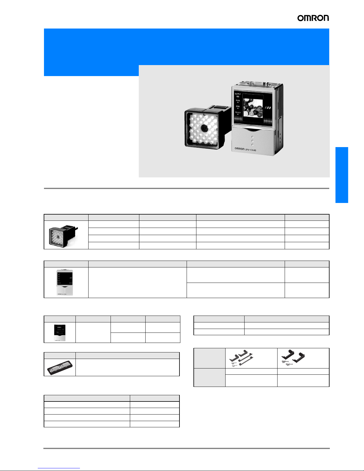
ZFV
C-1ZFV
Smart Vision Sensors
ZFV Color Series
Ordering Information
Models
Sensor Heads
Amplifier Units ZFV Color Series
Accessories ZFV Color Series (order separately)
Data Storage Units
Controller Link Unit
Sensor Head Extension Cable
Panel-mounting Adapter
External Lighting
Appearance Type Setting distance Sensing area Model
Narrow View 34 to 49 mm (variable) 5 × 4.6 mm to 9 × 8.3 mm (variable)
ZFV-SC10
Standard View 31 to 187 mm (variable) 10 × 9.2 mm to 50 × 46 mm (variable)
ZFV-SC50
Wide View 66 to 141 mm (variable) 50 × 46 mm to 90 × 83 mm (variable)
ZFV-SC90
Ultra-wide View 114 to 226 mm (variable) 90 × 83 mm to 150 × 138 mm (variable)
ZFV-SC150
Appearance Power supply Output type Model
24 VDC
NPN ZFV-CA40
PNP ZFV-CA45
Appearance Power supply Output type Model
24 VDC
NPN ZS-DSU11
PNP ZS-DSU41
Appearance Model
ZS-XCN
Cable length Model
3 m ZFV-XC3B
*1
*1.
ZFV-XC3BR Robot Cable is also available.
8 m ZFV-XC8B
Appearance
Model ZS-XOM1 ZS-XPM2
First Unit
Additional Units
(for expansion)
Typ e Model
Bar Lighting ZFV-LTL01
Bar Double Lighting ZFV-LTL02
Bar Low-angle Lighting ZFV-LTL04
Light Source for Through-beam Lighting ZFV-LTF01
Page 2
C-2 Vision Systems
Specifications
Sensor Heads
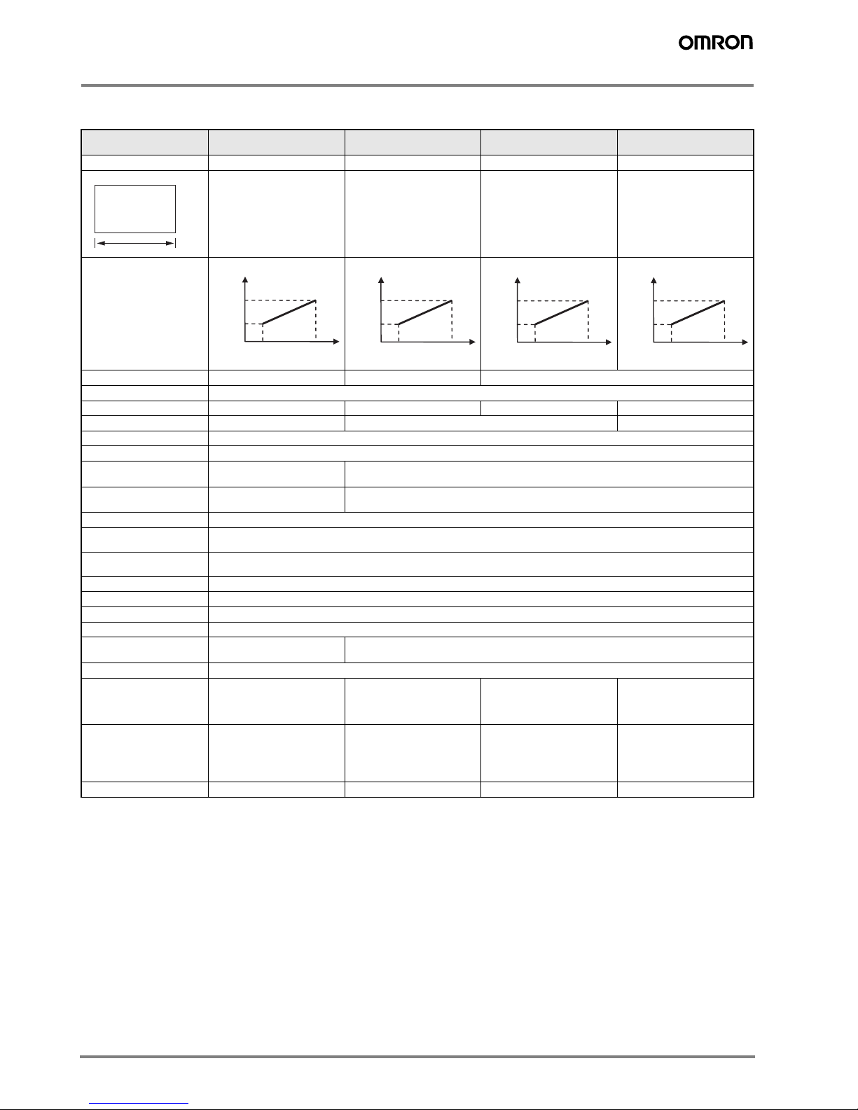
Item ZFV-SC10
(Narrow View)
ZFV-SC50/SC50W
(Standard View)
ZFV-SC90/SC90W
(Wide View)
ZFV-SC150/SC150W
(Ultra Wide View)
Setting distance (L)
34 to 49 mm (variable) 31 to 187 mm (variable)
67 to 142 mm (variable) 115 to 227 mm (variable)
Detection range (H × V)
5 × 4.6 mm to 9 × 8.3 mm
(variable)
10 × 9.2 mm to 50 × 46 mm
(variable)
50 × 46 mm to 90 × 83 mm
(variable)
90× 83 mm to 150 × 138 mm
(variable)
Relation between setting
distance and
detection range
Built-in lens
Focus: f15.65
Focus: f13.47 Focus: f6.1
Object lighting method
Pulse lighting
Object light source
8 white LEDs 36 LEDs 20 white LEDs 72 white LEDs
Lightning I/F (Option)
None Yes None
Sensing element
1/3-inch CCD
Shutter
Electronic shutter, shutter time: 1/500 to 1/8,000
Power supply voltage
15 VDC (Supplied from
Amplifier Unit.)
15 VDC, 48 VDC (Supplied from Amplifier Unit.)
Current consumption
Approx. 200 mA Approx. 350 mA [15 V: approx. 150 mA, 48 V: approx. 200 mA]
(Including the current consumed when external light is connected)
Dielectric strength
1,000 VAC, 50/60 Hz for 1 min
Vibration resistance
(destructive)
10 to 150 Hz, 0.35 mm single amplitude, 10 times each in X, Y, and Z directions for 8 min
Shock resistance
(destructive)
150 m/s2, three times each in six directions (up/down, left/right, forward/backward)
Ambient temperature
Operating: 0 to +40 °C, Storage: –25 to +65 °C (with no icing or condensation)
Ambient humidity
Operating and storage: 35% to 85% (with no condensation)
Ambient atmosphere
Must be free of corrosive gas.
Connection type
Prewired, Standard cable length: 2 m
Degree of protection
(
IEC 60529)
IP65 ZFV-SC___: IP65
ZFV-SC___W: IP67
Material
Case: ABS, Mounting bracket: PBT
Weight
Approx. 200 g
(including mounting bracket
and cord; packaged
condition: approx. 300 g)
Approx. 270 g
(including mounting bracket
and cord; packaged
condition: approx. 350 g)
Approx. 300 g
(including mounting bracket
and cord; packaged
condition: approx. 380 g)
Approx. 600 g
(including mounting bracket
and cord; packaged
condition: approx. 780 g)
Accessories
Mounting bracket
ZFV-XMF (1),
Ferrite core (1),
Instruction sheet
Mounting bracket
ZFV-XMF2 (1),
Ferrite core (2),
Warning label (1)
Instruction sheet
Mounting bracket
ZFV-XMF2 (1),
Ferrite core (2),
Warning label (1)
Instruction sheet
Ferrite core (2),
Instruction sheet
LED class
*1
Class 1 Class 2 Class 2 Class 1
*1.
Applicable standards: IEC60825-1: 1993 +A1:1997 +A2:2001, EN60825-1:1994 +A:2002 +A:2001
Detection
range
(V)
(H)
Setting distance (L)
49 mm
34 mm
5 mm 9 mm
Detection range(H)
10 mm
187 mm
31 mm
50 mm
Setting distance (L)
Detection range (H)
50 mm
142 mm
67 mm
90 mm
Detection range (H)
Setting distance (L)
90 mm
227 mm
115 mm
150 mm
Detection range (H)
Setting distance (L)
Page 3
ZFV
C-3ZFV
Amplifier Units
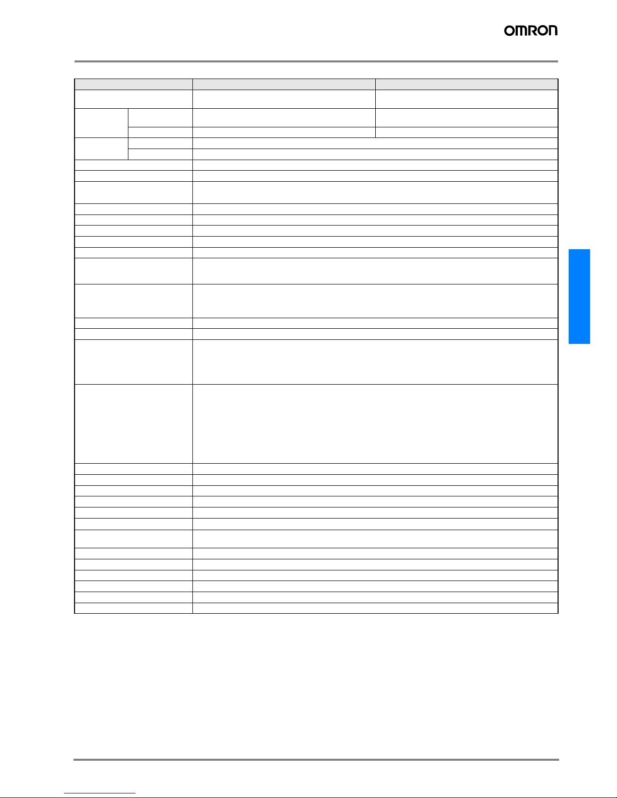
Item ZFV-CA40 ZFV-CA45
Output specifications NPN open collector, 30 VDC 50 mA max.,
residual voltage 1.2 V max.
PNP open collector, 50 mA max.,
residual voltage 1.2 V max.
Input
specifications
ON Short-circuited with 0 V terminal or 1.5 V or less Supply voltage short-circuited or within supply
voltage -1.5 V max.
OFF Open (leakage current 0.1 mA max) Open (leakage current 0.1 mA max)
Serial I/O USB2.0 1 port, full-speed (12 Mbps) MINI-B
RS-232C 1 port, 115,200 bps max.
Inspection items PATTERN, AREA, HUE (Color), WIDTH, POSITION, COUNT, BRIGHT, CHARA
Teaching area Rectangular, one area
Teaching area size • PATTERN, BRIGHT: Any rectangular area (256 × 256 max.)
• AREA, HUE (Color), WIDTH, POSITION, COUNT, CHARA: Any rectangular area (full screen max.)
Sensing area Full screen
Resolution 468 x 432 (H x V) max.
Bank switching Supported for 8 banks.
Image input interval 13 ms (Standard), 8 ms (1/2 for partial scan), 5 ms (1/4 for partial scan)
Other functions Control output switching: ON for OK / ON for NG, ON delay / OFF delay, One-shot output, "ECO" mode
Output signals (1) Control output (OUTPUT)
(2) Enable output (ENABLE)
(3) Error output (ERROR)
Input signals (1) Sync measurement input (TRIG)/Continuous measurement input (TRIG); switched by menu
(2) Bank selection inputs (BANK1-3)
(3) Workpiece still teaching (TEACH)/ Workpiece moving teaching (TEACH); switched by menu
Sensor head interface Digital interface
Image display 1.8 inch TFT ccolor LCD (Display dots: 557 x 234 pix)
Indicators • Judgment result indicator (OUTPUT, Color: orange)
• Inspection mode indicator (RUN, Color: green)
• Error indicator (ERR, Color: red)
• Ready status indicator (READY, Color: blue)
Operation interface • Cursor keys (up, down, left, right)
• Setting key (SET)
• Escape key (ESC)
• Operating mode switching (slide switch)
• Menu switching (slide switch)
• Teaching/Display switching key (TEACH/VIEW)
• Function keys (A to D 4 input)
Power supply voltage
20.4 to 26.4 VDC (including ripple)
Current consumption
800 mA max. (with Sensor Head connected)
Dielectric strength
1,000 VAC, 50/60 Hz for 1 min between leads and Amplifier Unit case
Noise resistance
1 kV, Pulse rise: 5 ns, Pulse width: 50 ns, Burst duration: 15 ms, Cycle: 300 ms
Vibration resistance (destructive) 10 to 150 Hz, 0.1 mm single amplitude, 10 times each in X, Y, and Z directions for 8 min
Shock resistance (destructive)
150 m/s2, three times each in six directions (up/down, left/right, forward/backward)
Ambient temperature range
Operating: 0 to 50 °C
Storage: –25 to 65 °C (with no icing or condensation)
Ambient humidity range
Operating and storage: 35% to 85% (with no condensation)
Ambient atmosphere
Must be free of corrosive gas.
Degree of protection
IEC 60529, IP20
Material
Polycarbonate (PC)
Weight
Approx. 300 g (including cord; packaged condition: 450 g)
Accessories
Ferrite core (1), Instruction sheet, Label (1)
Page 4
C-4 Vision Systems
External light units (optional)
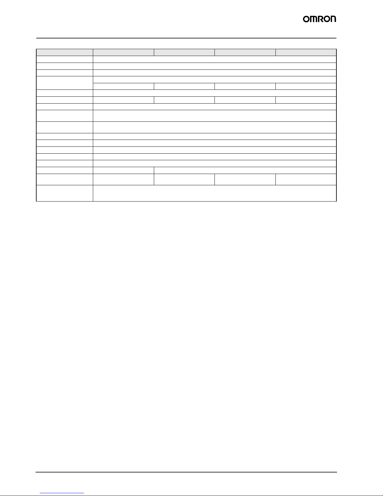
Item ZFV-LTF01 ZFV-LTL01 ZFV-LTL02 ZFV-LTL04
Applicable sensor head ZFV-SC50/SC50W/SC90/SC90W
Lighting method Pulse lighting
Lighting interval Fixed (1.1 to 1.4 ms)
Light source (Qty.) White LEDs
60 20 40 80
Power supply voltage 48 VDC (Supplied from sensor head)
Current consumption Appprox. 160 mA Appprox. 80 mA Appprox. 120 mA Appprox. 210 mA
Dielectric strength 300 VAC, 50/60 Hz for 1 min
Vibration resistance
(destructive)
10 to 150 Hz, 0.35 mm single amplitude, 10 times each in X, Y and Z directions for 8 min
Shock resistance
(destructive)
150 m/s
2
, 3 times each in six directions (up/down, left/right, forward/backward)
Ambient temperature Operating: 0 to 40 °C Storage: –20 to 65 °C (with no icing or condensation)
Ambient humidity Operating and storage: 35% to 85% RH (with no condensation)
Ambient atmosphere Must be free of corrosive gas
Connection type Prewired, Standard cable length: 2 m
Degree of protection IEC60529 IP20
Material SPCC SPCC, aluminium
Weight Approx. 500 g (when
packaged: Approx. 550 g)
Approx. 250 g (when
packaged: Approx. 300 g)
Approx. 650 g (when
packaged: Approx. 900 g)
Approx. 900 g (when
packaged: Approx. 1,150 g)
LED class Class 1
Applicable standards IEC0825-1: 1993 +A1:1997 +A2:2001
EN60825-1: 1994 +A1:2002 +A2:2001
Page 5
ZFV
C-5ZFV
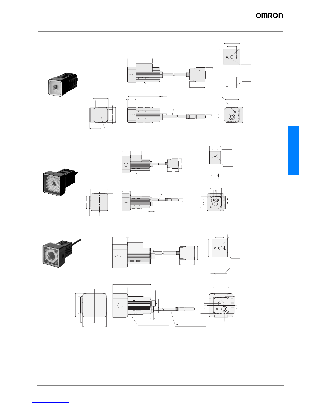
Dimensions (Units: mm)
20±0.1
Two, M4
Mounting Hole Dimensions
23.30
33.6
32
4.5 4.5
4.54.5
32
Optical axis
5.6
17.900.80
67.90
8.50
18.7 34
30.10
33
Connector
4
30
30
(6.36)
Focus adjustment dial
34
20
33.6
12.8 dia.
1/4-20UNC
Depth: 6
Mounting Bracket can be attached to any side
Heat-resistive vinyl-insulated cable
5.8 dia, standard length: 2 m
(6.36)
Two, M4
Depth: 6
Sensor Heads
ZFV-SC10 (Narrow view)
5.6
9.8
8.5
6.2 dia
Mounting Bracket can be attached to any side.
3
5
(6.36)
86
26.5
8
35.2
35.5
20±0.1
Two, M4
30.1
34
34
26.5
39
52.5
52.5
30.3
1/4-UNC
Depth: 6
34
38.9
20
Heat-resistive vinyl-insulated cable
6.2 dia, standard length: 2 m
Mounting Hole
Dimensions
Two, M4
Depth: 6
(6.36)
ZFV-SC50/SC50W (Standard view)
20
±
0.1
2-M4
30.25
52.5
52.5
39
Mounting hole dimensions
Heat-resistant PVC shielded cable
6.2 Standard length 2 m
20
34
38.9
34
83.7
4
8.5
8.5
7
8.5
35.5
35.5
33
33
5.6
9.8
6.2
33
30.1
A mounting bracket can be
mounted to each side
1/4-20UNC
Depth 6
2-M4
Depth 6
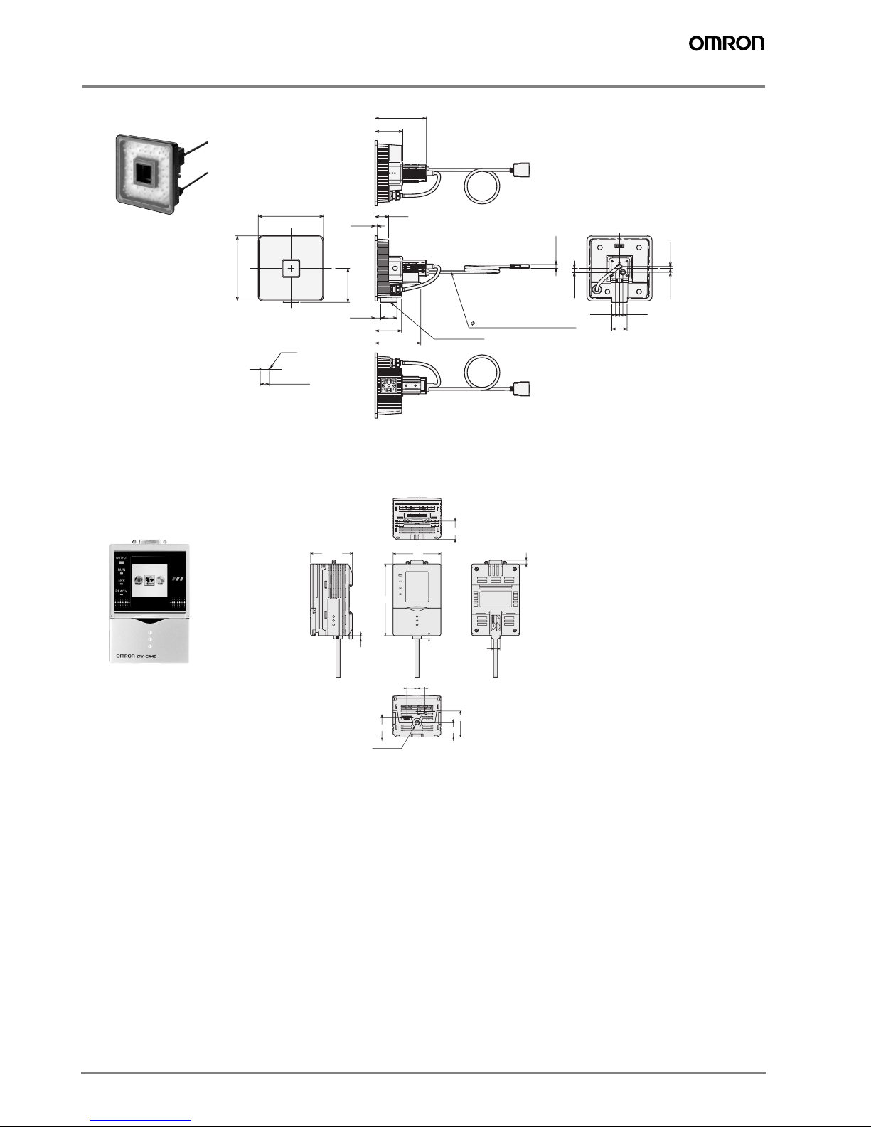
ZFV-SC90/SC90W (Wide view)
Page 6
C-6 Vision Systems
Amplifier Units
20 ± 0.1
2-M4
140
140
110.2
59.5
8.5
98
57
3512
5
29
8.5 4
8.5
8.5
33
7
73.2
Mounting hole dimensions
Heat-resistant PVC shielded cable
6.2 Standard length 2 m
Mounting surface
ZFV-SC150/SC150W (Ultra wide view)
3.90
4.30
4.61
10.80
1013
52.50
23.2
60
90
32.90
18
24.20
11.7 dia.
ZFV-CA4@
Page 7
ZFV
C-7ZFV
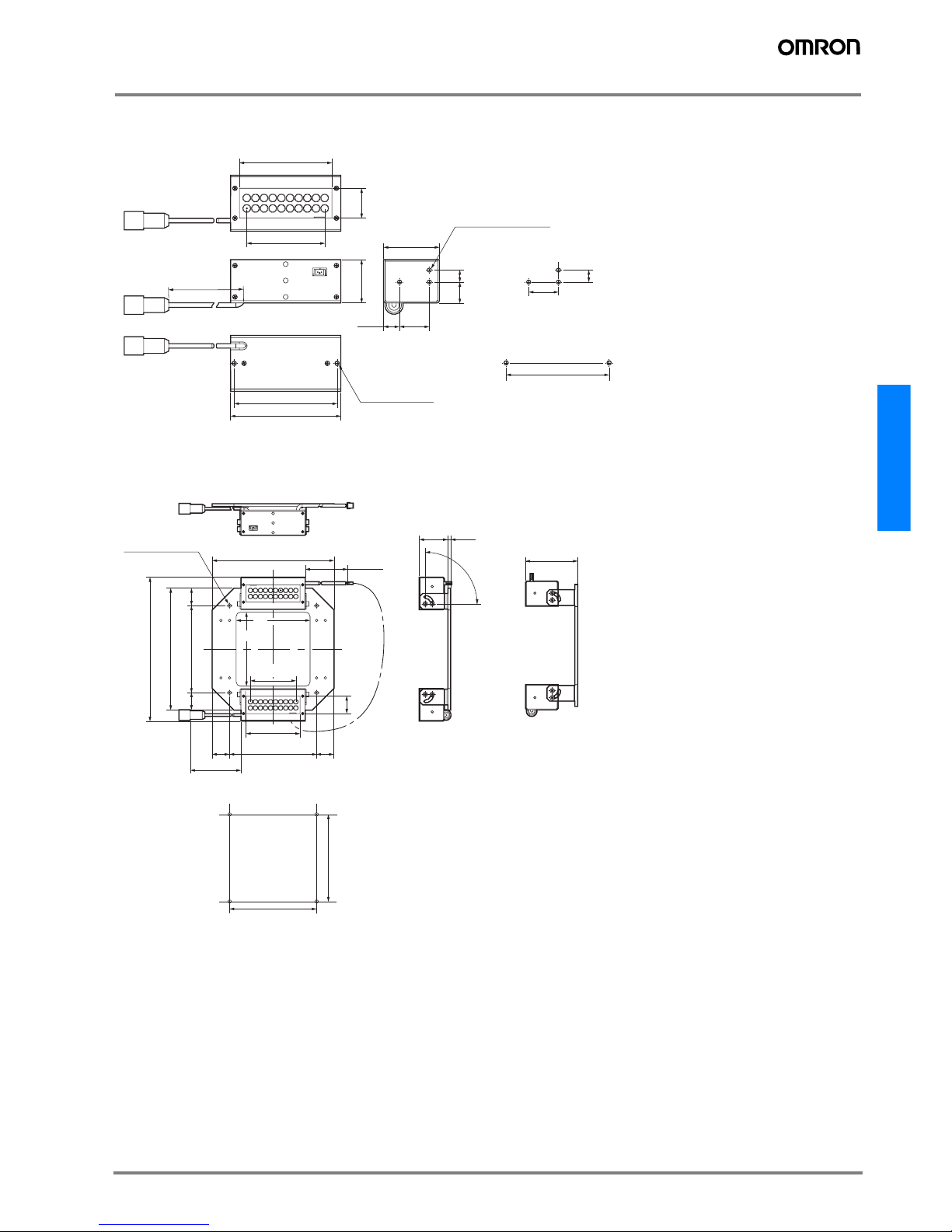
External light units (optional)
ZFV-LTL01 (bar lighting)
ZFV-LTL02 (bar double-lighting)
37.4
69
69 ± 0.1
74
20
20 ± 0.1
8 ± 0.1
10.7
29
8
14
2000
+100
0
62
20
P5.8 × 9 = 52.2
2 × 3-M3 Depth 5
2-M3 Depth 5
Mounting hole dimensions
Mounting hole dimensions
100 ± 0.1
100 ± 0.1
Mounting hole dimensions
59.9
85
85
140
3.233
100
2020
140
100
20
20
165.4
350
+35
0
2000
+100
0
90°
4-M4 (Thru)
20
62
P5.8 × 9 = 52.2
Page 8
C-8 Vision Systems
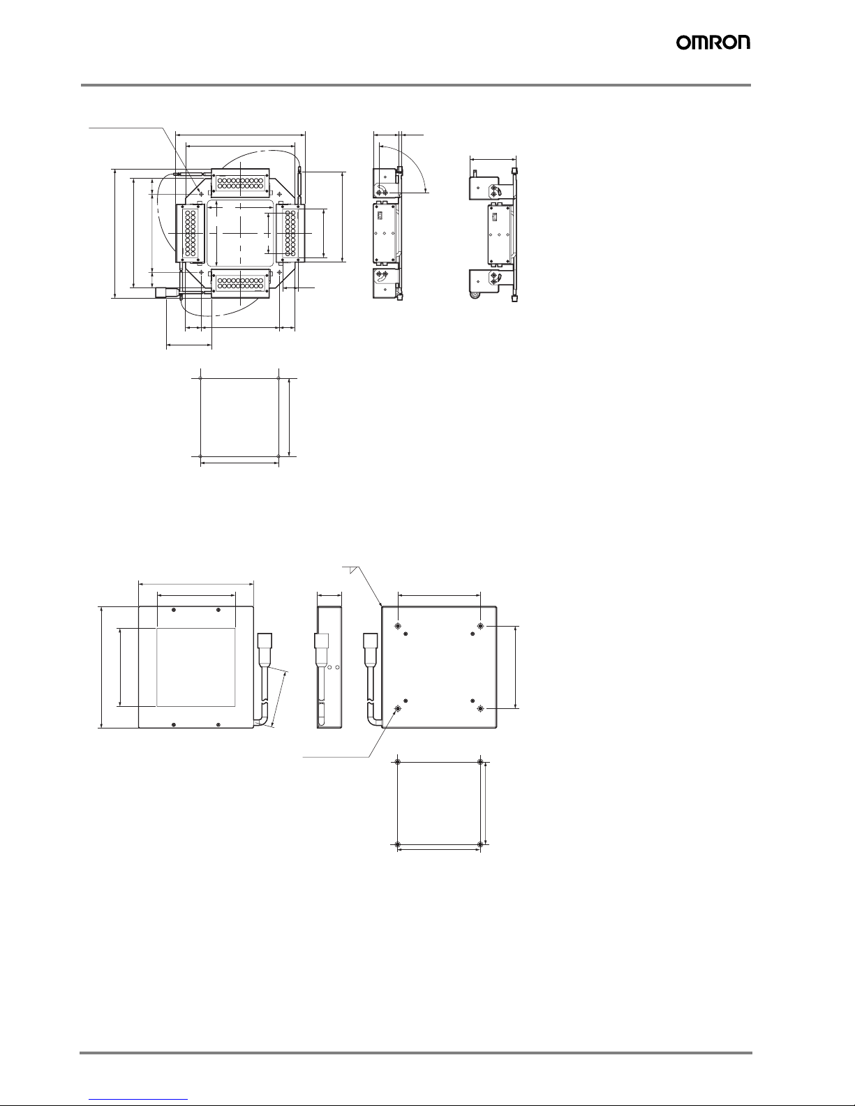
ZFV-LTL04 (bar low-angle lighting)
ZFV-LTF01 (light source for through-beam lighting)
350
+35
0
59.9
3.233
90°
140
165.4
100
2020
140
165.4
100
20
20
20
2000
+100
0
85
85
62
4-M4(Thru)
P5.8 × 9 = 52.2
100 ± 0.1
100 ± 0.1
Mounting hole dimensions
74 ± 0.1
74 ± 0.1
Mounting hole dimensions
74
74
22
2000
+100
0
103
1
70
109
4-M3 Depth 8
70
(Emitting surface)
(Emitting surface)
Page 9
ZFV
C-9ZFV
About the I/O cable
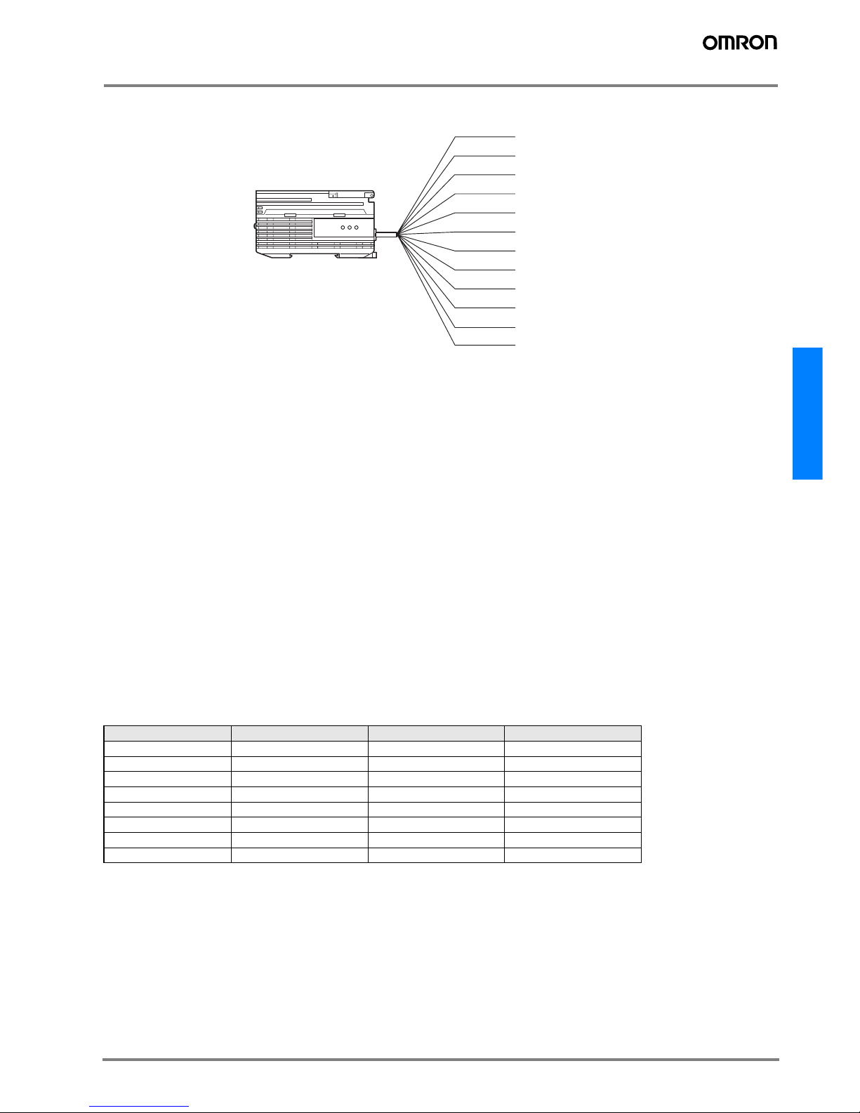
The following shows the leads that comprise the I/O cable.
(1) Power Supply
This connects the power supply.
Use a DC power supply with safe extra-low-voltage circuits to prevent high voltage.
Wire the power supply separately from other devices. Wiring them together or placing them in the same duct may cause induction, resulting
in malfunction or damage.
(2) GND
The GND terminal is the 0 V power supply terminal.
(3) OUTPUT (control output)
This outputs judgment results. This lead is interlocked with OUTPUT LED.
(4) ENABLE (enable output)
This turns ON when the sensor is ready for measurement.
(5) ERROR (error output)
This turns ON when an error is generated. This lead is interlocked with ERR LED.
(6) TEACH (teching input)
There are two teaching modes, workpiece stop teaching and workpiece move teaching. These teaching modes can be selected in the menu.
(7) TRIG (measurement trigger input)
There are two measurement modes, synchronus measurement and continuos measurement. Which mode of measurement is to be performed in is selected in the menu.
(8) BANK1 (bank swichting input 1)
(9) BANK2 (bank swichting input 2)
(10) BANK3 (bank swichting input 3)
The bank No. can be switched when the BANK1 to BANK3 are connected as follows
.
Bank No. BANK1 BANK2 BANK3
BANK1 OFF OFF OFF
BANK2 ON OFF OFF
BANK3 OFF ON OFF
BANK4ONONOFF
BANK5 OFF OFF ON
BANK6 ON OFF ON
BANK7 OFF ON ON
BANK8ONONON
(1) Power supply
(3) OUTPUT*
(4) ENABLE
(5) ERROR
(6) TEACH*
(7) TRIG*
(8) BANK1*
(9) BANK2*
(10) BANK3*
(2) GND
Brown
Blue
Black
Orange
Light blue
Yellow
Pink
Gray
Green
Red
* : Enabled only in the RUN mode
Purple
White
Unused
Unused
Page 10

C-10 Vision Systems
I/O Circuit diagrams
NPN output type (ZFV-CA40)
PNP output type (ZFV-CA45)
Brown
Blue
Black
Orange
Light blue
Load
Load
Load
Power supply (24VDC)
24VDC
Yellow
Pink
Gray
Green
Red
OUTPUT
ENABLE
ERROR
GND(0V)
TEACH
TRIG
BANK1
BANK2
BANK3
Internal circuits
Brown
Blue
Black
Orange
Light blue
Load
Power (24VDC)
OUTPUT
ENABLE
ERROR
GND(0V)
24VDC
Yellow
Pink
Gray
Green
TEACH
TRIG
BANK1
BANK2
Red BANK3
Load
Load
Internal circuits
Page 11
ZFV
C-11ZFV
Timing Charts
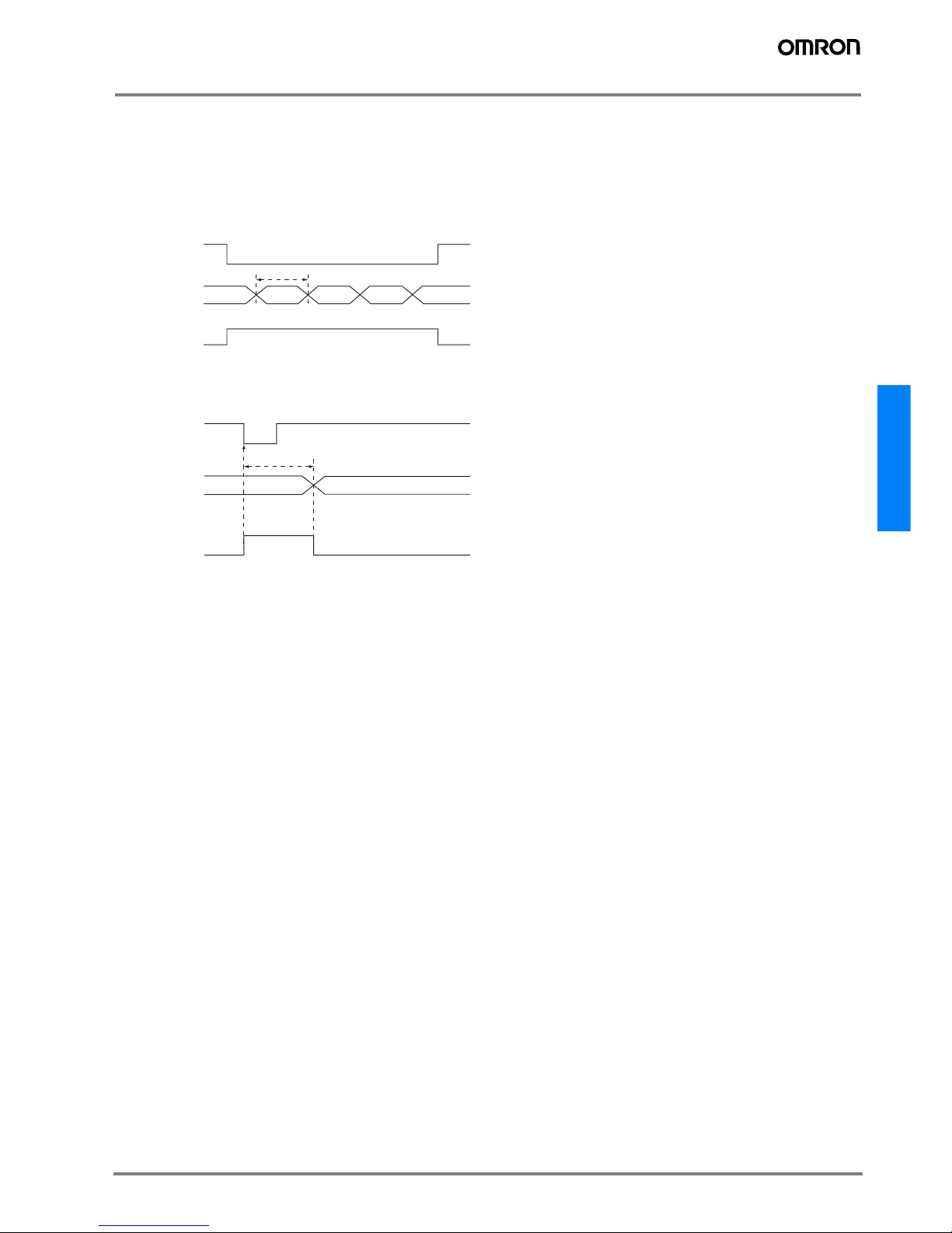
The following shows the timing charts when communication is performed with external devices.
Measurement
Continuos measurement
Measurement is performed continuosly for the duration that the TRIG signal is ON.
The measurement result is updated and output to external deveices at each measurement cycle.
Synchronuos measurement
Measurement is performed only once in synchrnous with the change in TRIG signal state from OFF to ON and the result is output.
• The minimum ON time width of the TRIG signal is 1 ms.
• The OUTPUT signal is helad until the measurement result is updated.
Note:However, when one-shot is set, the OUTPUT signal is held for the preset time.
To ut
TRIG
OUTPUT
ENABLE
OFF
ON
OFF
ON
OFF
ON
Tout: Measurement cycle
The measurement cycle changes
depending on the setting.
To ut
TRIG
OUTPUT
ENABLE
OFF
ON
OFF
ON
OFF
ON
Tout: Measurement time.
The measurement time changes
depending on the setting.
Page 12
C-12 Vision Systems
Teaching
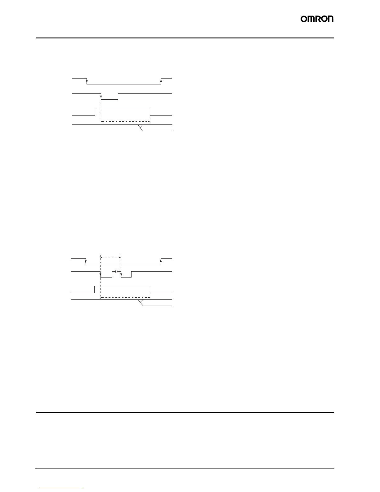
Workpiece stop teaching
Teaching processing is performed according to TRIG signal input after the TEACH signal input.
Measurement is not performed while teaching is being performed. Do not move the workpiece until teaching is completed.
(1) Turn the TEACH signal ON.
(2) Confirm that the ENABLE signal has turned OFF.
(3) Make sure that the workpiece to be taught is in the teaching area.
(4) Input the TRIG signal.
(5) The ENABLE signal turns ON after teaching is completed. At this timing, check the state of the ERROR signal.
(6) When teaching has been completed successfully, the ERROR signal stays OFF.
(7) When teaching fails, the ERROR signal turns ON.
(8) Turn the TEACH signal OFF and end teaching processing.
When teaching fails, the state before teaching was initiated is returned to. Performe teaching again.
If the TEACH signal is turned OFF midway, teaching is disabled.
Workpiece move teaching
Use this teaching mode when the object cannot be stopped. Teaching processing is divided up and performed in synchronous with the
TRIG signal input after the TEACH signal is input.
Teaching must be processewd eight times. Measurement is not performed while teaching is being performed.
(1) Turn the TEACH signal ON from the outside.
(2) Confirm that the ENABLE signal has turned OFF.
(3) Input the TRIG signal at the timing for measuring the workpiece to be taught.
(4) Repeat the input in step (3) eight times. (Trigger inputs from the ninth time onwars are ignored.)
(5) The ENABLE signal turns ON after teaching is completed. Check the state of the ERROR signal at this timing.
(6) When teaching has been completed successfully, the ERROR signal stays OFF.
(7) When teaching fails, the ERROR signal turns ON.
(8) Turn the TEACH signal OFF and end teaching processing.
When teaching fails, the state before teaching was initiated is return to. Perform teaching again.
If the TEACH signal is turned OFF midway, teaching is disabled.
During teaching processing
TRIG
OFF
ON
TEACH
OFF
ON
ENABLE
OFF
ON
ERROR
OFF
ON
(1)
(2)
(4)
(5)
(7)
(6)
(8)
During teaching processing
Min.150ms
TEACH
OFF
ON
(1) (8)
ERROR
OFF
ON
(6)
(7)
ENABLE
OFF
ON
(2) (5)
TRIG
OFF
ON
(3)
(4)
In the interest of product improvement, specifications are subject to change without notice.Cat. No. E373-E2-02A-X
OMRON EUROPE B.V.
Wegalaan 67-69,
NL-2132 JD, Hoofddorp,
The Netherlands
Phone: +31 23 568 13 00
Fax: +31 23 568 13 88
www.eu.omron.com
 Loading...