

Page 1

Cat. No. Z183-E1-01A
OPERATION MANUAL
ZEN Programmable Relay
Page 2

Page 3

ZEN Programmable Relay
Operation Manual
Produced May 2003
Page 4

Terms and Conditions of Sale
1. Offer; Acceptance. These terms and conditions (these "Terms") are deemed
part of all quotes, agreements, purchase orders, acknowledgments, price lists,
catalogs, manuals, brochures and other documents, whether electronic or in
writing, relating to the sale of products or services (collectively, the "Products
by Omron Electronics LLC and its subsidiary companies (“Omron
objects to any terms or conditions proposed in Buyer’s purchase order or other
documents which are inconsistent with, or in addition to, these Terms.
2. Prices; Payment Terms.
out notice by Omron. Omron reserves the right to increase or decrease prices
on any unshipped portions of outstanding orders. Payments for Products are
due net 30 days unless otherwise stated in the invoice.
3. Discounts.
sent to Buyer after deducting transportation charges, taxes and duties, and will
be allowed only if (i) the invoice is paid according to Omron’s payment terms
and (ii) Buyer has no past due amounts.
Omron, at its option, may charge Buyer 1-1/2% interest per month or
4. Interest.
the maximum legal rate, whichever is less, on any balance not paid within the
stated terms.
. Omron will accept no order less than $200 net billing.
5. Orders
6. Governmental Approvals.
costs involved in, obtaining any government approvals required for the importation or sale of the Products.
. All taxes, duties and other governmental charges (other than general
7. Taxes
real property and income taxes), including any interest or penalties thereon,
imposed directly or indirectly on Omron or required to be collected directly or
indirectly by Omron for the manufacture, production, sale, delivery, importation, consumption or use of the Products sold hereunder (including customs
duties and sales, excise, use, turnover and license taxes) shall be charged to
and remitted by Buyer to Omron.
8. Financial.
to Omron, Omron reserves the right to stop shipments or require satisfactory
security or payment in advance. If Buyer fails to make payment or otherwise
comply with these Terms or any related agreement, Omron may (without liability and in addition to other remedies) cancel any unshipped portion of Products sold hereunder and stop any Products in transit until Buyer pays all
amounts, including amounts payable hereunder, whether or not then due,
which are owing to it by Buyer. Buyer shall in any event remain liable for all
unpaid accounts.
9. Cancellation; Etc.
unless Buyer indemnifies Omron against all related costs or expenses.
10. Force Majeure
resulting from causes beyond its control, including earthquakes, fires, floods,
strikes or other labor disputes, shortage of labor or materials, accidents to
machinery, acts of sabotage, riots, delay in or lack of transportation or the
requirements of any government authority.
11. Shipping; Delivery.
a.Shipments shall be by a carrier selected by Omron; Omron will not drop ship
except in “break down” situations.
b.Such carrier shall act as the agent of Buyer and delivery to such carrier shall
constitute delivery to Buyer;
c. All sales and shipments of Products shall be FOB shipping point (unless oth-
erwise stated in writing by Omron), at which point title and risk of loss shall
pass from Omron to Buyer; provided that Omron shall retain a security inter-
est in the Products until the full purchase price is paid;
d.Delivery and shipping dates are estimates only; and
e.Omron will package Products as it deems proper for protection against nor-
mal handling and extra charges apply to special conditions.
Any claim by Buyer against Omron for shortage or damage to the
12. Claims.
Products occurring before delivery to the carrier must be presented in writing
to Omron within 30 days of receipt of shipment and include the original transportation bill signed by the carrier noting that the carrier received the Products
from Omron in the condition claimed.
13. Warranties
Products will be free from defects in materials and workmanship for a period of
twelve months from the date of sale by Omron (or such other period expressed
in writing by Omron). Omron disclaims all other warranties, express or implied.
(b) Limitations
EXPRESS OR IMPLIED, ABOUT NON-INFRINGEMEN T, MERCHANTABIL-
All prices stated are current, subject to change with-
Cash discounts, if any, will apply only on the net amount of invoices
Buyer shall be responsible for, and shall bear all
If the financial position of Buyer at any time becomes unsatisfactory
Orders are not subject to rescheduling or cancellation
. Omron shall not be liable for any delay or failure in delivery
Unless otherwise expressly agreed in writing by Omron:
. (a) Exclusive Warranty. Omron’s exclusive warranty is that the
. OMRON MAKES NO WARRANTY OR REPRESENTATION,
”). Omron
ITY OR FITNESS FOR A PARTICULAR PURPOSE OF THE PRODUCTS.
BUYER ACKNOWLEDGES THAT IT ALONE HAS DETERMINED THAT THE
PRODUCTS WILL SUITABLY MEET THE REQUIREMENTS OF THEIR
")
INTENDED USE. Omron further disclaims all warranties and responsibility of
any type for claims or expenses based on infringement by the Products or otherwise of any intellectual property right. (c) Buyer Remedy
gation hereunder shall be, at Omron’s election, to (i) replace (in the form
originally shipped with Buyer responsible for labor charges for removal or
replacement thereof) the non-complying Product, (ii) repair the non-complying
Product, or (iii) repay or credit Buyer an amount equal to the purchase price of
the non-complying Product; provided that in no event shall Omron be responsible for warranty, repair, indemnity or any other claims or expenses regarding
the Products unless Omron’s analysis confirms that the Products were properly handled, stored, installed and maintained and not subject to contamination, abuse, misuse or inappropriate modification. Return of any Products by
Buyer must be approved in writing by Omron before shipment. Omron Companies shall not be liable for the suitability or unsuitability or the results from the
use of Products in combination with any electrical or electronic components,
circuits, system assemblies or any other materials or substances or environments. Any advice, recommendations or information given orally or in writing,
are not to be construed as an amendment or addition to the above warranty.
See http://oeweb.omron.com or contact your Omron representative for published information.
14. Limitation on Liability; Etc
FOR SPECIAL, INDIRECT, INCIDENTAL, OR CONSEQUENTIAL DAMAGES,
LOSS OF PROFITS OR P RODUCTION OR COM MERCIAL LOSS IN AN Y
WAY CONNECTED WITH THE PRODUCTS, WHETHER SUCH CLAIM IS
BASED IN CONTRACT, WARRANTY, NEGLIGENCE OR STRICT LIABILITY.
Further, in no event shall liability of Omron Companies exceed the individual
price of the Product on which liability is asserted.
15. Indemnities
16. Property; Confidentiality.
17. Export Controls.
18. Miscellaneous
. Buyer shall indemnify and hold harmless Omron Companies and
their employees from and against all liabilities, losses, claims, costs and
expenses (including attorney's fees and expenses) related to any claim, investigation, litigation or proceeding (whether or not Omron is a party) which arises
or is alleged to arise from Buyer's acts or omissions under these Terms or in
any way with respect to the Products. Without limiting the foregoing, Buyer (at
its own expense) shall indemnify and hold harmless Omron and defend or settle any action brought against such Companies to the extent based on a claim
that any Product made to Buyer specifications infringed intellectual property
rights of another party.
sive property of Omron Companies and Buyer shall not attempt to duplicate it
in any way without the written permission of Omron. Notwithstanding any
charges to Buyer for engineering or tooling, all engineering and tooling shall
remain the exclusive property of Omron. All information and materials supplied
by Omron to Buyer relating to the Products are confidential and proprietary,
and Buyer shall limit distribution thereof to its trusted employees and strictly
prevent disclosure to any third party.
licenses regarding (i) export of products or information; (iii) sale of products to
“forbidden” or other proscribed persons; and (ii) disclosure to non-citizens of
regulated technology or information.
and no course of dealing between Buyer and Omron shall operate as a waiver
of rights by Omron. (b) Assignment
without Omron's written consent. (c) Law.
law of the jurisdiction of the home office of the Omron company from which
Buyer is purchasing the Products (without regard to conflict of law principles). (d) Amendment
Buyer and Omron relating to the Products, and no provision may be changed
or waived unless in writing signed by the parties. (e) Severability
sion hereof is rendered ineffective or invalid, such provision shall not invalidate
any other provision. (f) Setoff
against the amount owing in respect of this invoice. (g) Definitions
herein, “including
nies” (or similar words) mean Omron Corporation and any direct or indirect
subsidiary or affiliate thereof.
. OMRON COMPANIES SHALL NOT BE LIABLE
Any intellectual property in the Products is the exclu-
Buyer shall comply with all applicable laws, regulations and
. (a) Waiver. No failure or delay by Omron in exercising any right
. Buyer may not assign its rights hereunder
. These Terms constitute the entire agreement between
. Buyer shall have no right to set off any amounts
” means “including without limitation”; and “Omron Compa-
Certain Precautions on Specifications and Use
1. Suitability of Use. Omron Companies shall not be responsible for conformity
with any standards, codes or regulations which apply to the combination of the
Product in the Buyer’s application or use of the Product. At Buyer’s request,
Omron will provide applicable third party certification documents identifying
ratings and limitations of use which apply to the Product. This information by
itself is not sufficient for a complete determination of the suitability of the Product in combination with the end product, machine, system, or other application
or use. Buyer shall be solely responsible for determining appropriateness of
the particular Product with respect to Buyer’s application, product or system.
Buyer shall take application responsibility in all cases but the following is a
non-exhaustive list of applications for which particular attention must be given:
(i) Outdoor use, uses involving potential chemical contamination or electrical
interference, or conditions or uses not described in this document.
(ii) Use in consumer products or any use in significant quantities.
(iii) Energy control systems, combustion systems, railroad systems, aviation
systems, medical equipment, amusement machines, vehicles, safety equipment, and installations subject to separate industry or government regulations.
(iv) Systems, machines and equipment that could present a risk to life or property. Please know and observe all prohibitions of use applicable to this Product.
NEVER USE THE PRODUCT FOR AN APPLICATION INVOLVING SERIOUS
RISK TO LIFE OR PROPERTY OR IN LARGE QUANTITIES WITHOUT
ENSURING THAT THE SYSTEM AS A WHOLE H AS BEEN DESIGNED TO
ADDRESS THE RISKS, AND THAT THE OMRON’S PRODUCT IS PROPERLY RATED AND INSTALLED FOR THE INTENDED USE WITHIN TH E
OVERALL EQUIPMENT OR SYSTEM.
2. Programmable Products.
user’s programming of a programmable Product, or any consequence thereof.
3. Performance Data
and other materials is provided as a guide for the user in determining suitability and does not constitute a warranty. It may represent the result of Omron’s
test conditions, and the user must correlate it to actual application requirements. Actual performance is subject to the Omron’s Warranty and Limitations
of Liability.
4. Change in Specifications
changed at any time based on improvements and other reasons. It is our practice to change part numbers when published ratings or features are changed,
or when significant construction changes are made. However, some specifications of the Product may be changed without any notice. When in doubt, special part numbers may be assigned to fix or establish key specifications for
your application. Please consult with your Omron’s representative at any time
to confirm actual specifications of purchased Product.
5. Errors and Omissions.
checked and is believed to be accurate; however, no responsibility is assumed
for clerical, typographical or proofreading errors or omissions.
Omron Companies shall not be responsible for the
. Data presented in Omron Company websites, catalogs
. Product specifications and accessories may be
Information presented by Omron Companies has been
. Omron’s sole obli-
These Terms are governed by the
. If any provi-
. As used
Page 5

Notice:
OMRON products are manufactured for use according to proper procedures by a
qualified operator and only for the purposes described in this manual.
The following conventions are used to indicate and classify precautions in this manual. Always heed the information provided with them. Failure to heed precautions
can result in injury to people or damage to property.
!DANGER Indicates an imminently hazardous situation which, if not avoided, will
result in death or serious injury.
!WARNING Indicates a potentially hazardous situation which, if not avoided, could
result in death or serious injury.
!Caution Indicates a potentially hazardous situation which, if not avoided, may
result in minor or moderate injury, or property damage.
v
Page 6
OMRON Product References
All OMRON products are capitalized in this manual. The word “Unit” is also capitalized when it refers to an OMRON product, regardless of whether or not it appears in
the proper name of the product.
Visual Aids
The following headings appear in the left column of the manual to help you locate different types of information.
Note
Indicates information of particular interest for efficient and convenient
operation of the product.
1,2,3... 1. Indicates lists of one sort or another, such as procedures, check-
lists, etc.
Precaution Indicates precautionary information that should be heeded in using
the ZEN.
RUN
PARAMETE R
SET CL OCK
LANGUAGE
▲▼
Indicates that the display (the word “LANGUAGE” in this case) is
flashing. In this manual, this state is described by saying that the
“flashing cursor” is at the word “LANGUAGE”. In this state it is possible to change settings and the position of the cursor.
LANGUAGE
Indicates that the display (the letter “H” in this case) is flashing in
reverse video. In this manual, this state is described by saying that
ENGLISH
the “highlighted cursor” is at the word “H”. In this state it is not possible to change settings but the cursor can be changed to the flashing
cursor by pressing the OK button.
Indicate the buttons that needs to be pressed in operating procedures. Press each button once.
Indicate buttons that needs to be pressed in operating procedures.
Press one of the buttons once or more.
Ó OMRON, 2003
All rights reserved. No part of this publication may be reproduced, stored in a retrieval system, or transmitted, in any form, or by any means, mechanical, electronic, photocopying,
recording, or otherwise, without the prior written permission of OMRON.
No patent liability is assumed with respect to the use of the information contained herein.
Moreover, because OMRON is constantly striving to improve its high-quality products, the
information contained in this manual is subject to change without notice. Every precaution
has been taken in the preparation of this manual. Nevertheless, OMRON assumes no
responsibility for errors or omissions. Neither is any liability assumed for damages resulting
from the use of the information contained in this publication.
vi
Page 7

TABLE OF CONTENTS
PRECAUTIONS . . . . . . . . . . . . . . . . . . . . . . . . . . . . . . . . . . . . . . . .xi
1 Safety Precautions . . . . . . . . . . . . . . . . . . . . . . . . . . . . . . . . . . . . . . . . . . . . . xii
2 Application Precautions. . . . . . . . . . . . . . . . . . . . . . . . . . . . . . . . . . . . . . . . . xiii
3 Operating Environment Precautions . . . . . . . . . . . . . . . . . . . . . . . . . . . . . . . xvi
4 Conformance to EC Directives . . . . . . . . . . . . . . . . . . . . . . . . . . . . . . . . . . . xvi
5 Operating Mode at Startup. . . . . . . . . . . . . . . . . . . . . . . . . . . . . . . . . . . . . . . xix
6 Memory Backup. . . . . . . . . . . . . . . . . . . . . . . . . . . . . . . . . . . . . . . . . . . . . . . xx
7 Version Upgrades . . . . . . . . . . . . . . . . . . . . . . . . . . . . . . . . . . . . . . . . . . . . . . xxi
SECTION 1
Outline . . . . . . . . . . . . . . . . . . . . . . . . . . . . . . . . . . . . . . . . . . . . . . . . 1
1-1 Outline . . . . . . . . . . . . . . . . . . . . . . . . . . . . . . . . . . . . . . . . . . . . . . . . . . . . . . 2
1-2 Features and Part Names . . . . . . . . . . . . . . . . . . . . . . . . . . . . . . . . . . . . . . . . 8
1-3 Display Screen and Basic Operations . . . . . . . . . . . . . . . . . . . . . . . . . . . . . . 16
1-4 Memory Areas . . . . . . . . . . . . . . . . . . . . . . . . . . . . . . . . . . . . . . . . . . . . . . . . 27
1-5 Allocating I/O Bit Numbers. . . . . . . . . . . . . . . . . . . . . . . . . . . . . . . . . . . . . . 29
1-6 Preparations for Operation. . . . . . . . . . . . . . . . . . . . . . . . . . . . . . . . . . . . . . . 30
SECTION 2
Installation and Wiring . . . . . . . . . . . . . . . . . . . . . . . . . . . . . . . . . .31
2-1 Mounting . . . . . . . . . . . . . . . . . . . . . . . . . . . . . . . . . . . . . . . . . . . . . . . . . . . . 32
2-2 Wiring . . . . . . . . . . . . . . . . . . . . . . . . . . . . . . . . . . . . . . . . . . . . . . . . . . . . . . 33
SECTION 3
Programming and Operating Methods . . . . . . . . . . . . . . . . . . . . .49
3-1 Selecting Display Language . . . . . . . . . . . . . . . . . . . . . . . . . . . . . . . . . . . . . 50
3-2 Setting the Date and Time . . . . . . . . . . . . . . . . . . . . . . . . . . . . . . . . . . . . . . . 51
3-3 Creating Ladder Programs . . . . . . . . . . . . . . . . . . . . . . . . . . . . . . . . . . . . . . . 52
3-4 Confirming Ladder Program Operation. . . . . . . . . . . . . . . . . . . . . . . . . . . . . 62
3-5 Correcting Ladder Programs . . . . . . . . . . . . . . . . . . . . . . . . . . . . . . . . . . . . . 64
3-6 Using Timers (T) and Holding Timers (#). . . . . . . . . . . . . . . . . . . . . . . . . . . 67
3-7 Using Counters (C) . . . . . . . . . . . . . . . . . . . . . . . . . . . . . . . . . . . . . . . . . . . . 70
3-8 Using Weekly Timers (@) . . . . . . . . . . . . . . . . . . . . . . . . . . . . . . . . . . . . . . . 72
3-9 Using Calendar Timers (*). . . . . . . . . . . . . . . . . . . . . . . . . . . . . . . . . . . . . . . 74
3-10 Analog Inputs (Analog Comparators (A)). . . . . . . . . . . . . . . . . . . . . . . . . . . 75
3-11 Comparing Timer/Counter Present Values Using Comparators (P) . . . . . . . 79
3-12 Displaying Messages (Display Bits (D)) . . . . . . . . . . . . . . . . . . . . . . . . . . . . 82
3-13 Using Button Switches (B) . . . . . . . . . . . . . . . . . . . . . . . . . . . . . . . . . . . . . . 85
vii
Page 8

TABLE OF CONTENTS
SECTION 4
Special Functions. . . . . . . . . . . . . . . . . . . . . . . . . . . . . . . . . . . . . . . 87
4-1 Protecting Programs. . . . . . . . . . . . . . . . . . . . . . . . . . . . . . . . . . . . . . . . . . . . 88
4-2 Stabilizing Input Operations. . . . . . . . . . . . . . . . . . . . . . . . . . . . . . . . . . . . . . 90
4-3 Changing Backlight Automatic Cutout Time. . . . . . . . . . . . . . . . . . . . . . . . . 92
4-4 Adjusting LCD Screen Contrast. . . . . . . . . . . . . . . . . . . . . . . . . . . . . . . . . . . 93
4-5 Setting Summertime. . . . . . . . . . . . . . . . . . . . . . . . . . . . . . . . . . . . . . . . . . . . 93
4-6 Reading System Information . . . . . . . . . . . . . . . . . . . . . . . . . . . . . . . . . . . . . 94
SECTION 5
Optional Products . . . . . . . . . . . . . . . . . . . . . . . . . . . . . . . . . . . . . . 95
5-1 Mounting Battery Units . . . . . . . . . . . . . . . . . . . . . . . . . . . . . . . . . . . . . . . . . 96
5-2 Using Memory Cassettes . . . . . . . . . . . . . . . . . . . . . . . . . . . . . . . . . . . . . . . . 97
5-3 Connecting the ZEN Support Software . . . . . . . . . . . . . . . . . . . . . . . . . . . . . 99
SECTION 6
Troubleshooting. . . . . . . . . . . . . . . . . . . . . . . . . . . . . . . . . . . . . . . . 101
6-1 Troubleshooting . . . . . . . . . . . . . . . . . . . . . . . . . . . . . . . . . . . . . . . . . . . . . . . 102
6-2 Error Messages. . . . . . . . . . . . . . . . . . . . . . . . . . . . . . . . . . . . . . . . . . . . . . . . 102
6-3 Deleting Error Messages . . . . . . . . . . . . . . . . . . . . . . . . . . . . . . . . . . . . . . . . 104
Appendices
A Product Configurations . . . . . . . . . . . . . . . . . . . . . . . . . . . . . . . . . . . . . . . . . 105
B Specifications . . . . . . . . . . . . . . . . . . . . . . . . . . . . . . . . . . . . . . . . . . . . . . . . 109
C Ladder Program Execution . . . . . . . . . . . . . . . . . . . . . . . . . . . . . . . . . . . . . . 121
D Application Examples . . . . . . . . . . . . . . . . . . . . . . . . . . . . . . . . . . . . . . . . . . 123
E Allocations and Setting Sheets . . . . . . . . . . . . . . . . . . . . . . . . . . . . . . . . . . . 137
Index . . . . . . . . . . . . . . . . . . . . . . . . . . . . . . . . . . . . . . . . . . . . . . . . . 145
Revision History . . . . . . . . . . . . . . . . . . . . . . . . . . . . . . . . . . . . . . . 149
viii
Page 9

About this Manual:
This manual describes the installation and operation of the ZEN Programmable
Relay and includes the sections described below.
Please read this manual carefully and be sure you understand the information
provided before attempting to install or operate the ZEN. Be sure to read the
precautions provided in the following section.
Precautions provides general precautions for using the ZEN and related
devices.
Section 1 gives an outline of the ZEN, including example applications, the system configurations and basic operations.
Section 2 explains how to mount and wire the ZEN CPU Units and Expansion
I/O Units.
Section 3 explains how to create and edit ladder programs and how to use the
timers, counters, comparators, display function and buttons switches.
Section 4 describes how to protect ladder programs, stabilize inputs, make
LCD screen adjustments, and make summer time settings.
Section 5 describes how to mount Battery Units, use Memory Cassettes, and
how to connect the ZEN Support Software.
Section 6 lists the error messages and provides probable causes and countermeasures for troubleshooting.
The following two manuals are provided for the ZEN Programmable Relay.
Refer to them as required in operation.
Manual Contents Cat. No.
ZEN Programmable Relay
Operation Manual
ZEN Support Software
Operation Manual
ZEN specifications, functions, and operating methods.
Installation and operating procedures for
the ZEN Support Software
Z183
Z184
!WARNING Failure to read and understand the information provided in this manual may
result in personal injury or death, damage to the product, or product failure.
Please read each section in its entirety and be sure you understand the information provided in the section and related sections before attempting any of
the procedures or operations given.
ix
Page 10

Page 11

PRECAUTIONS
This section provides general precautions for using the ZEN Programmable Relay.
The information contained in this section is important for the safe and reliable application
of the ZEN. You must read this section and understand the information contained before
attempting to set up or operate the ZEN.
1 Safety Precautions . . . . . . . . . . . . . . . . . . . . . . . . . . . . . . . . . . . . . . . . . . . . . xii
2 Application Precautions. . . . . . . . . . . . . . . . . . . . . . . . . . . . . . . . . . . . . . . . . xiii
2-1 Circuit Design and Ladder Programming . . . . . . . . . . . . . . . . . . . xiii
2-2 Installation . . . . . . . . . . . . . . . . . . . . . . . . . . . . . . . . . . . . . . . . . . . xiii
2-3 Wiring and Connections. . . . . . . . . . . . . . . . . . . . . . . . . . . . . . . . . xiii
2-4 I/O Connections and Startup Precautions . . . . . . . . . . . . . . . . . . . xiv
2-5 Handling. . . . . . . . . . . . . . . . . . . . . . . . . . . . . . . . . . . . . . . . . . . . . xiv
2-6 Maintenance. . . . . . . . . . . . . . . . . . . . . . . . . . . . . . . . . . . . . . . . . . xv
2-7 Transportation and Storage . . . . . . . . . . . . . . . . . . . . . . . . . . . . . . xv
3 Operating Environment Precautions . . . . . . . . . . . . . . . . . . . . . . . . . . . . . . . xvi
4 Conformance to EC Directives . . . . . . . . . . . . . . . . . . . . . . . . . . . . . . . . . . . xvi
4-1 Applicable Directives. . . . . . . . . . . . . . . . . . . . . . . . . . . . . . . . . . . xvi
4-2 Concepts. . . . . . . . . . . . . . . . . . . . . . . . . . . . . . . . . . . . . . . . . . . . . xvi
4-3 Conformance to EC Directives . . . . . . . . . . . . . . . . . . . . . . . . . . . xvii
4-4 Relay Output Noise Reduction Methods . . . . . . . . . . . . . . . . . . . . xvii
5 Operating Mode at Startup. . . . . . . . . . . . . . . . . . . . . . . . . . . . . . . . . . . . . . . xix
6 Memory Backup. . . . . . . . . . . . . . . . . . . . . . . . . . . . . . . . . . . . . . . . . . . . . . . xx
7 Version Upgrades . . . . . . . . . . . . . . . . . . . . . . . . . . . . . . . . . . . . . . . . . . . . . . xxi
7-1 Application Precautions for Differences between Versions. . . . . . xxii
7-2 CPU Units Covered in this Manual . . . . . . . . . . . . . . . . . . . . . . . . xxiii
xi
Page 12

Safety Precautions 1
1 Safety Precautions
!WARNING Never attempt to disassemble any Units while power is being
supplied. Doing so may result in serious electrical shock or electrocution.
!WARNING Never touch the I/O terminals, computer connector, Expansion
Unit connector, or Battery Unit connector while power is being
supplied. Doing so may result in serious electrical shock or electrocution.
!WARNING Provide safety measures in external circuits (i.e., not in the ZEN),
including the following items, to ensure safety in the system if an
abnormality occurs due to malfunction of the ZEN or another
external factor affecting the ZEN operation. Not doing so may
result in serious accidents.
• Emergency stop circuits, interlock circuits, limit circuits, and similar safety measures must be provided in external control circuits.
• The ZEN will turn OFF all outputs when its self-diagnosis function detects any error. As a countermeasure for such errors,
external safety measures must be provided to ensure safety in
the system.
• The ZEN outputs may remain ON or OFF due to deposition or
burning of the output relays or destruction of the output transistors. As a countermeasure for such problems, external safety
measures must be provided to ensure safety in the system.
• Provide double safety mechanisms to handle incorrect signals
that can be generated by broken signal lines or momentary
power interruptions.
!WARNING Do not short the battery terminals or charge, disassemble, heat,
or incinerate the battery. Do not subject the battery to strong
shocks. Doing any of these may result in leakage, rupture, heat
generation, or ignition of the battery. Dispose of any battery that
has been dropped on the floor or otherwise subjected to excessive shock. Batteries that have been subjected to shock may leak
if they are used.
!Caution Tighten the AC power supply terminal block screws to the torque
specified in the manual. Loose screws can result in fire or faulty
operation.
xii
Page 13

Application Precautions 2
2 Application Precautions
Observe the following precautions when using the ZEN.
2-1 Circuit Design and Ladder Programming
• Provide external interlock circuits, limit circuits, and other safety
circuits in addition to any provided within the ZEN to ensure
safety.
• The output relays or the output transistors may remain ON due to
faults in internal circuits such as output relays or output transistors. As a countermeasure for such problems, external safety
measures must be provided to ensure safety in the system.
• Always turn ON power to the ZEN before turning ON power to
the I/O circuits. If the ZEN power supply is turned ON after the I/
O power supply, temporary errors may result in operation.
• The life of the output relays is largely affected by the switching
conditions. Confirm the operation of the system under actual
operating conditions and set the switching frequency to ensure
that adequate performance will be provided. Insulation faults and
burning in the ZEN may result if relays are used after their performance has deteriorated.
2-2 Installation
• Install the ZEN according to instructions in the operation manual.
Improper installation may cause faulty operation.
• Do not install the ZEN in locations subject to excessive noise.
Malfunction may occur.
• Do not allow the ZEN to fall during installation.
• Be sure that all the mounting screws on the ZEN and Expansion
I/O Unit are tightened to the torque specified in the manual.
Incorrect tightening torque may result in malfunction.
• Use with the cover of the computer connector mounted. Using
without the cover may result in malfunction due to dust or other
foreign matter.
• Be sure that the DIN rail mounting levers, Expansion I/O Units,
Memory Cassettes, Battery Units, cable connectors, and other
items with locking devices are properly locked into place.
Improper locking may result in malfunction.
2-3 Wiring and Connections
• Use the wires specified in this manual when wiring. Use straight
crimp terminals when connecting loose wires.
xiii
Page 14

Application Precautions 2
• Provide circuit breakers and other safety measures to provide
protection against shorts in external wiring.
• Use separate wiring ducts for signal wires from those used for
power supply and high-voltage lines.
• Always check polarity when connecting cables.
• Leave the label attached to the Unit when wiring. Removing the
label may result in malfunction if foreign matter enters the Unit.
• Remove the label after the completion of wiring to ensure proper
heat dissipation. Leaving the label attached may result in malfunction.
• Tighten the terminal block screws to the torque specified in the
manual.
• Wire the ZEN according to instructions in the operation manual.
Improper installation may cause faulty operation.
2-4 I/O Connections and Startup Precautions
• Use the Units only with the power supplies and voltages specified in the operation manual. Other power supplies and voltages
may damage the Units.
• Take measures to stabilize the power supply to conform to the
rated supply if it is not stable.
• Do not apply voltages exceeding the rated input voltage to input
circuits. The input circuits may be destroyed.
• Do not apply voltages exceeding the maximum switching capacity to output circuits. The output circuits may be destroyed.
• Double-check all wiring before turning ON the power supply.
Incorrect wiring may result in burning.
• Check the user program for proper execution before actually running it on the Unit. Not checking the program may result in an
unexpected operation.
2-5 Handling
• Use, store, and transport the ZEN under the limits given for general specifications in this manual.
• Do not attempt to disassemble, repair, or modify any Units. Any
attempt to do so may result in malfunction, fire, or electric shock.
• Always turn OFF the power supply to the ZEN before attempting
any of the following.
xiv
• Assembling the ZEN.
• Attaching or removing the Expansion I/O Unit.
• Connecting or disconnecting any cables or wiring.
Page 15

Application Precautions 2
• Attaching or removing the Memory Cassette.
• Attaching or removing the Battery Unit.
• Confirm that no adverse effect will occur in the system before
attempting any of the following. Not doing so may result in an
unexpected operation.
• Changing the operating mode.
• Using the button switches.
• Changing bit status or parameter settings.
• Before touching a Unit, be sure to first touch a grounded metallic
object in order to discharge any static build-up.
• Do not pull on the cables or bend the cables beyond their natural
limit. Doing either of these may break the cables.
• Do not place objects on top of the cables or other wiring lines.
Doing so may break the cables.
• Do not short the battery terminals or charge, disassemble, heat,
or incinerate the battery. Do not subject the battery to strong
shocks. Doing any of these may result in leakage, rupture, heat
generation, or ignition of the battery. Dispose of any battery that
has been dropped on the floor or otherwise subjected to excessive shock. Batteries that have been subjected to shock may
leak if they are used.
• Abide by all local ordinances and regulations when disposing of
the ZEN.
2-6 Maintenance
• When replacing parts, be sure to confirm that the rating of a new
part is correct.
• When replacing a Unit, transfer to the new Unit and confirm all
settings for clock data, internal holding bits, holding timers, and
counter before starting operation again.
2-7 Transportation and Storage
• Use special packaging boxes when transporting the ZEN and do
not subject it to excessive shock or vibration or drop it during
shipment.
• Store the ZEN in the following temperature and humidity ranges
without condensation or icing.
Model Ambient
temperature
LCD –20 to 75°C 10% to 90%
LED –40 to 75°C
Humidity
xv
Page 16

Operating Environment Precautions 3
3 Operating Environment Precautions
Do not operate the control system in the following places.
• Where the ZEN is exposed to direct sunlight.
• Where the ambient temperature or humidity is beyond the specified ranges.
• Where the ZEN may be affected by condensation due to radical
temperature changes.
• Where there is any corrosive or inflammable gas.
• Where there is excessive dust, saline air, or metal powder.
• Where the ZEN is affected by vibration or shock.
• Where any water, oil or chemical may splash on the ZEN.
• Any other place with conditions beyond those specified in the
general specifications.
Take appropriate and sufficient countermeasures when installing systems in the following locations:
• Locations subject to static electricity or other forms of noise.
• Locations subject to strong electromagnetic fields.
• Locations subject to possible exposure to radioactivity.
• Locations close to power supplies.
4 Conformance to EC Directives
4-1 Applicable Directives
•EMC Directives
• Low Voltage Directive
4-2 Concepts
EMC Directives
OMRON devices that comply with EC Directives also conform
to the related EMC standards so that they can be more easily
built into other devices or the overall machine. The actual
products have been checked for conformity to EMC standards
(see the following note). Whether the products conform to the
standards in the system used by the customer, however, must
be checked by the customer.
EMC-related performance of the OMRON devices that comply
with EC Directives will vary depending on the configuration,
xvi
Page 17

Conformance to EC Directives 4
wiring, and other conditions of the equipment or control panel
on which the OMRON devices are installed. The customer
must, therefore, perform the final check to confirm that devices
and the overall machine conform to EMC standards.
Note Applicable EMC (Electromagnetic Compatibility) standards are as
follows:
EMS (Electromagnetic Susceptibility): EN61000-6-2
EMI (Electromagnetic Interference): EN50081-2
(Radiated emission: 10-m regulations)
Low Voltage Directive
Always ensure that devices operating at voltages of 50 to
1,000 VAC and 75 to 1,500 VDC meet the required safety
standards for the ZEN (EN61131-2).
4-3 Conformance to EC Directives
The ZEN complies with EC Directives. To ensure that the machine or
device in which the ZEN is used complies with EC Directives, the
ZEN must be installed as follows:
1,2,3... 1. The ZEN must be installed within a control panel.
2. You must use reinforced insulation or double insulation for the DC
power supplies used for the communications power supply and I/
O power supplies.
3. ZEN models complying with EC Directives also conform to the
Common Emission Standard (EN50081-2). Radiated emission
characteristics (10-m regulations) may vary depending on the
configuration of the control panel used, other devices connected
to the control panel, wiring, and other conditions.
You must therefore confirm that the overall machine or equipment
complies with EC Directives.
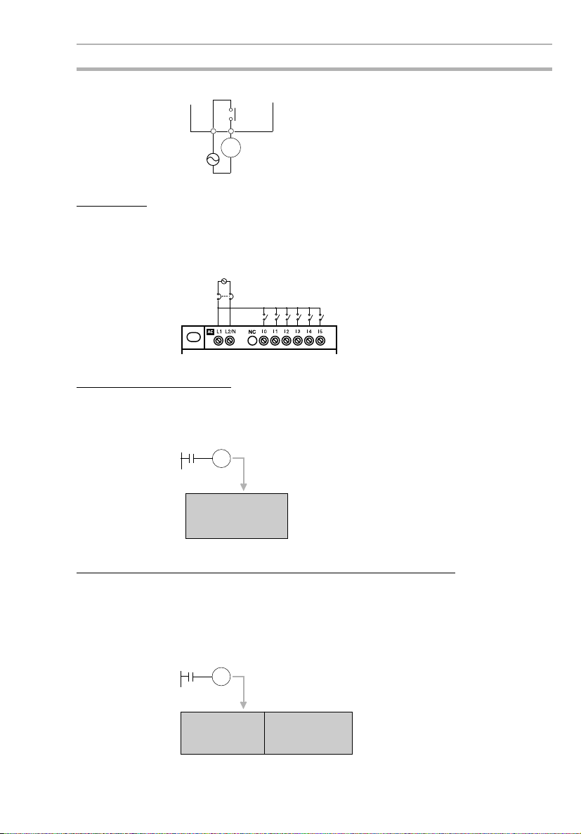
4-4 Relay Output Noise Reduction Methods
The ZEN conforms to the Common Emission Standards (EN50081-2)
of the EMC Directives. However, noise generated by relay output
switching may not satisfy these Standards. In such a case, a noise filter must be connected to the load side or other appropriate countermeasures must be provided external to the ZEN.
Countermeasures taken to satisfy the standards vary depending on
the devices on the load side, wiring, configuration of machines, etc.
Following are examples of countermeasures for reducing the generated noise.
xvii
Page 18
Conformance to EC Directives 4
Countermeasures
(Refer to EN50081-2 for more details.)
Countermeasures are not required if the frequency of load switching
for the whole system with the ZEN included is less than 5 times per
minute.
Countermeasures are required if the frequency of load switching for
the whole system with the ZEN included is more than 5 times per
minute.
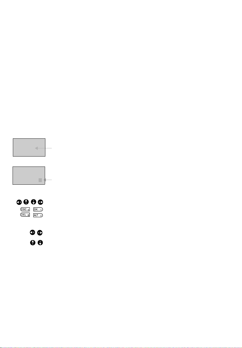
Countermeasure Examples
When switching an inductive load, connect an surge protector,
diodes, etc., in parallel with the load or contact as shown below.
Circuit Current Characteristic Required element
AC DC
CR method Yes Yes If the load is a relay or
Powe r
supply
Inductive
load
solenoid, there is a time
lag between the moment
the circuit is opened and
the moment the load is
reset.
If the supply voltage is 24
or 48 V, insert the surge
protector in parallel with
the load. If the supply voltage is 100 to 200 V, insert
the surge protector
between the contacts.
The capacitance of the capacitor must be 1 to 0.5
contact current of 1 A and
resistance of the resistor must
be 0.5 to 1
age of 1 V. These values, however, vary with the load and
the characteristics of the relay.
Decide these values from
experiments, and take into
consideration that the capacitance suppresses spark discharge when the contacts are
separated and the resistance
limits the current that flows
into the load when the circuit is
closed again.
The dielectric strength of the
capacitor must be 200 to 300
V. If the circuit is an AC circuit,
use a capacitor with no polarity.
W per contact volt-
mF per
xviii
Page 19
Operating Mode at Startup 5
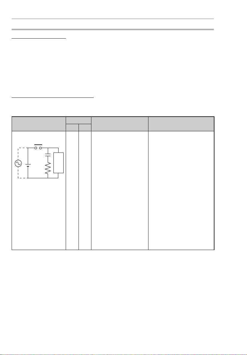
Circuit Current Characteristic Required element
AC DC
Diode method No Yes The diode connected in
Powe r
supply
Varistor method Yes Yes The varistor method pre-
Powe r
supply
Inductive
load
Inductive
load
parallel with the load
changes energy accumulated by the coil into a current, which then flows into
the coil so that the current
will be converted into
Joule heat by the resistance of the inductive
load.
This time lag, between
the moment the circuit is
opened and the moment
the load is reset, caused
by this method is longer
than that caused by the
CR method.
vents the imposition of
high voltage between the
contacts by using the constant voltage characteristic of the varistor. There is
time lag between the
moment the circuit is
opened and the moment
the load is reset.
If the supply voltage is 24
or 48 V, insert the varistor
in parallel with the load. If
the supply voltage is 100
to 200 V, insert the varistor between the contacts.
The reversed dielectric
strength value of the diode
must be at least 10 times as
large as the circuit voltage
value. The forward current of
the diode must be the same as
or larger than the load current.
The reversed dielectric
strength value of the diode
may be two to three times
larger than the supply voltage
if the surge protector is
applied to electronic circuits
with low circuit voltages.
---
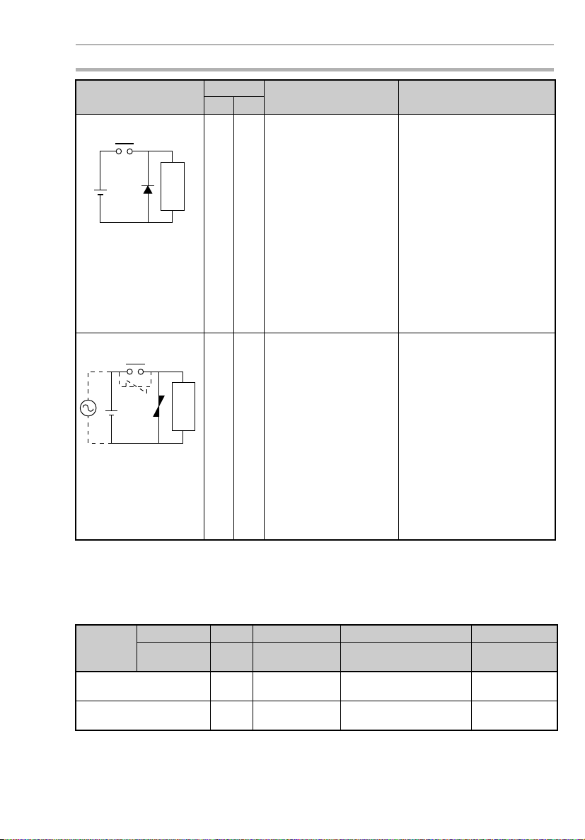
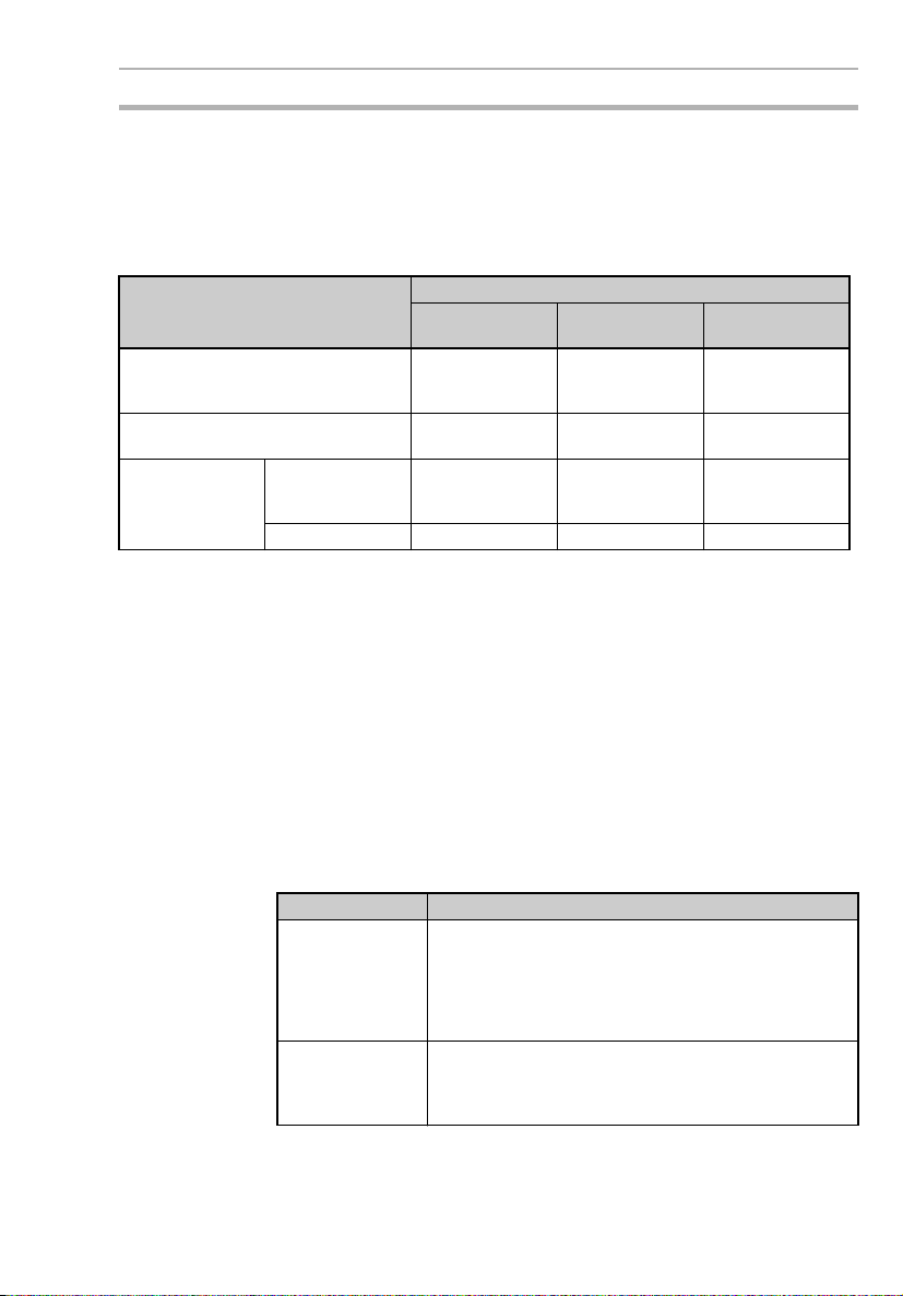
5 Operating Mode at Startup
The operating mode at startup depends on the model and the presence of a user program as shown in the following table.
User
program
LCD model (with LCD and
operation buttons)
LED model (with LED and
no operation buttons)
In CPU No Yes No Yes
In Memory
Cassette
No No Yes Yes
STOP
mode
STOP
mode
RUN mode with
program in CPU
RUN mode with
program in CPU
RUN mode with program
in Memory Cassette
RUN mode with program
in Memory Cassette
RUN mode with
program in CPU
RUN mode with
program in CPU
xix
Page 20

Memory Backup 6
6 Memory Backup
The ladder program and settings are stored in EEPROM and thus will
not be lost even if the power supply is turned OFF for an extended
period of time (e.g., 2 days at 25°C). The status of the following data,
however, is backed up by an internal capacitor, and may be lost if
power is turned OFF for an extended period of time: ON/OFF status
of holding bits (H), holding timers (#), and counters (C) and the prevent value areas. For models equipped with a clock/calendar, the
time and date may be reset. Always reconfirm system operation
before restarting operation after the power has been turned OFF for
an extended period of time. We recommend that a Battery Unit be
(optional) connected in any system in which power may be interrupted for an extended period of time.
xx
Page 21

Version Upgrades 7
7 Version Upgrades
The following table shows the relationship between the versions and
functionality of the ZEN CPU Unit and ZEN Support Software
Date of
upgrade
January
2002
May
2003
System
software
version
Ver. 1.10 The following functions were added to the CPU
Ver. 2.00 • The number of timers, counters, weekly tim-
Units with LCD displays.
• A Clear Display function
• A Day/Month display object (DAT1)
ers, calendar timers, and display areas was
increased from 8 to 16 each and the number
of holding timers was increased from 4 to 8.
(See note 2.)
• A new CPU Unit with 20 I/O points was
added. (See note 2.)
• The input circuits of CPU Units with DC
power supply were made compatible with
both PNP and NPN.
• A password input was added to the memory
all clear function for CPU Units with LCDs.
Note The model numbers of CPU Units with
CPU Unit Support Software
Main changes
The following functions
were added to version
2.00 (ZEN-SOFT01-V2).
• Support for changes to
display function
• Simulation function
• Improvements to functions, operating procedures, and displays
The following functions
were added to version
3.00 (ZEN-SOFT01-V3).
• Support for V1 CPU
Units with 20 I/O points
• Support for V1 CPU
Units with 10 I/O points
10 or 20 I/O points end in “-V1.”
Note 1. The number of the system software version in the CPU Unit is not
related to the model number. The system software version of
CPU Units with LCDs can be read by selecting SYSTEM INFO
from the OTHER Menu. “V02.00” will be displayed as the system
software version for V1 CPU Units.
xxi
Page 22
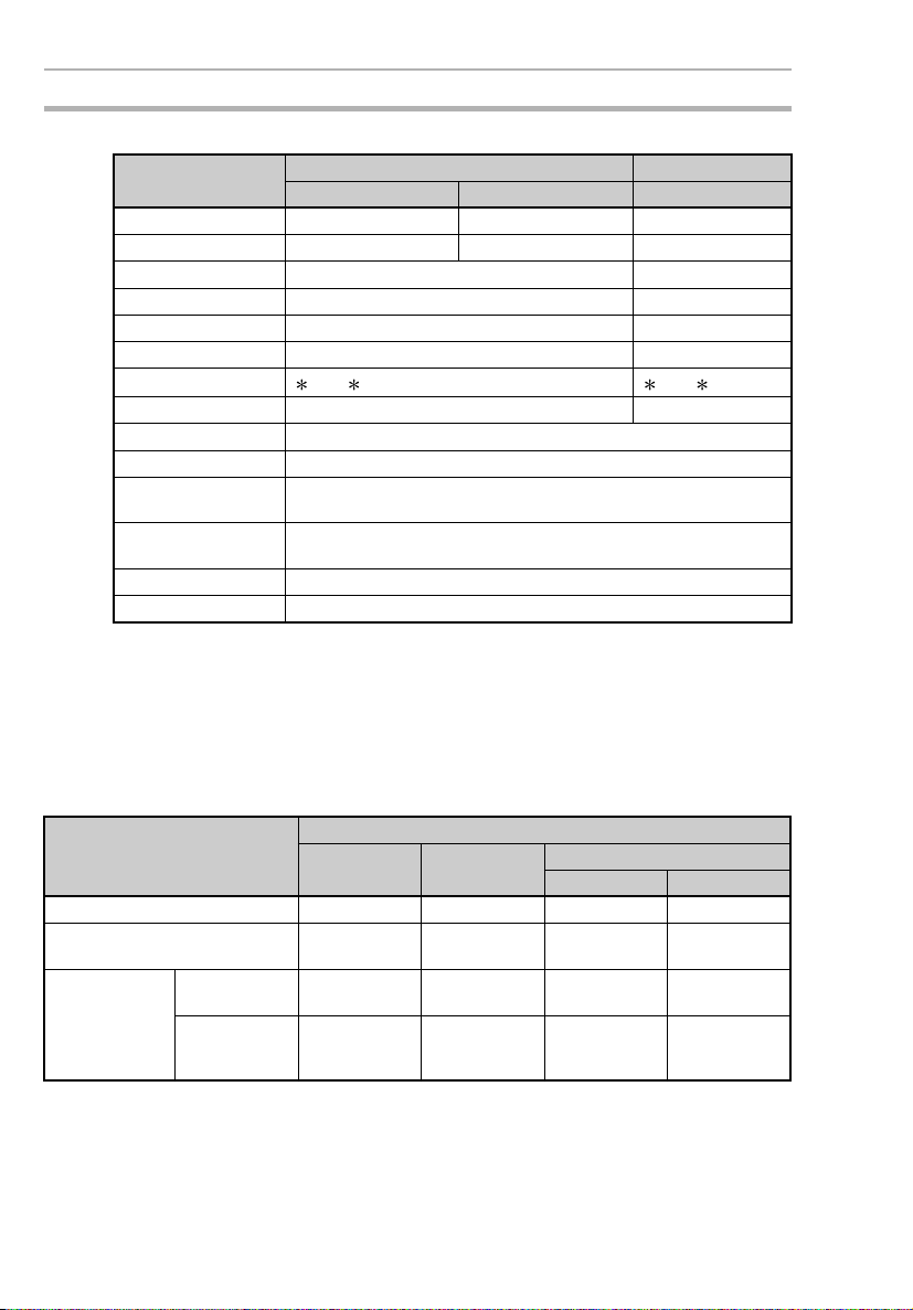
Version Upgrades 7
2. Memory Area Comparison between V1 and Pre-V1 CPU Units
Area V1 CPU Units Pre-V1 CPU Units
ZEN-10C@@@-@-V1 ZEN-20C@@@-@-V1 ZEN-10C@@@-@
CPU Unit input bits I0 to I5 (6 bits) I0 to Ib (12 bits) I0 to I5 (6 bits)
CPU Unit output bits Q0 to Q3 (4 bits) Q0 to Q7 (8 bits) Q0 to Q3 (4 bits)
Timers T0 to Tf (16 bits) T0 to T7 (8 bits)
Holding timers #0 to #7 (8 bits) #0 to #3 (4 bits)
Counters C0 to Cf (16 bits) C0 to C7 (8 bits)
Weekly timers @0 to @f (16 bits) @0 to @f7(8 bits)
Calendar timers
Displays D0 to Df (16 bits) D0 to D7 (8 bits)
Work bits M0 to Mf (16 bits)
Holding bits H0 to Hf (16 bits)
Expansion I/O Unit
input bits
Expansion I/O Unit
output bits
Analog comparators A0 to A3 (4 bits)
Comparators P0 to Pf (16 bits)
0 to f (16 bits) 0 to 7 (8 bits)
X0 to Xb (12 bits)
Y0 to Yb (12 bits)
7-1 Application Precautions for Differences between
Versions
Memory Cassette Compatibility
Be aware of the following restrictions when using a Memory Cassette
containing a program that was stored from a CPU Unit with a different
version of system software.
Version of CPU Unit used to
write the Memory Cassette
Ver. 1.00 OK OK OK OK
Ver. 1.10 Restrictions
Ver. 2.00
(V1 CPU Units)
10 I/O points Restrictions
20 I/O points Restrictions
Version of CPU Unit used to read the Memory Cassette
Ver. 1.00 Ver. 1.10 Ver. 2.20 (V1 CPU Units)
10 I/O points 20 I/O points
(See note 1.)
(See note 1.)
(See notes 1,
2, and 3.)
OK OK OK
Restrictions
(See note 2.)
Restrictions
(See notes 2
and 3.)
OK OK
Restrictions
(See note 3.)
OK
xxii
Note 1. The new display functions (display clear: -CD@ and day/month
display: DAT1) cannot be used and will be ignored.
Page 23
Version Upgrades 7
2. Only the memory area ranges supported by the pre-V1 CPU
Units can be used for Timers, Holding Timers, Counters, Weekly
Timers, Calendar Timers, and Displays (i.e., only half of each).
3. Only 6 inputs and 4 outputs can be used in the CPU Unit I/O bits.
Any others will be ignored.
Compatibility of Programs Depending on Support Software Version
CPU Unit system software Support Software
Ver. 1.00
ZEN-SOFT01
Ver. 1.00 OK OK Restrictions
Ver. 1.10 Restrictions
Ver. 2.00
(V1 CPU Units)
10 I/O points Restrictions
20 I/O points Not applicable. Not applicable. OK
(See note 1.)
(See notes 1 and
2.)
Ver. 2.00
ZEN-SOFT01-V2
OK Restrictions
Restrictions
(See note 2.)
Ver. 3.00
ZEN-SOFT01-V3
(See notes 1 and
2.)
(See note 2.)
OK
Note 1. The new display functions (display clear: -CD@ and day/month
display: DAT1) cannot be used and will be ignored.
2. Only the memory area ranges supported by the pre-V1 CPU
Units can be used for Timers, Holding Timers, Counters, Weekly
Timers, Calendar Timers, and Displays (i.e., only half of each).
7-2 CPU Units Covered in this Manual
The material in this manual is based on the memory areas of the V1
CPU Units. If you are using a pre-V1 CPU Unit, the sizes of some of
the memory areas will be different. Refer to page xxii for details.
Also, the I/O circuits and I/O terminal arrangements for CPU Units for
DC power supply different between V1 and pre-V1 CPU Units, as
described in the following table. Refer to page 38 for details
CPU Unit I/O circuits
V1 CPU Units With CPU Units for DC power supply, the common is
Pre-V1 CPU Units The negative size of the power supply for input circuits
separated from the power supply circuit in the I/O circuits, and a COM (common) terminal is provided for
input terminals. This enables connecting devices with
sourcing outputs (+ common) in addition to connecting
devices with sinking outputs (
is connected internally to the negative side of the DC
power supply. The input circuits can thus be used only
with a
- common.
- common).
xxiii
Page 24

Version Upgrades 7
xxiv
Page 25

SECTION 1
Outline
This section gives an outline of the ZEN, including example applications, the system
configurations and basic operations.
1-1 Outline . . . . . . . . . . . . . . . . . . . . . . . . . . . . . . . . . . . . . . . . . . . . . . . . . . . . . . 2
1-2 Features and Part Names . . . . . . . . . . . . . . . . . . . . . . . . . . . . . . . . . . . . . . . . 8
1-2-1 Features and System Configuration. . . . . . . . . . . . . . . . . . . . . . . . 8
1-2-2 Part Names. . . . . . . . . . . . . . . . . . . . . . . . . . . . . . . . . . . . . . . . . . . 10
1-3 Display Screen and Basic Operations . . . . . . . . . . . . . . . . . . . . . . . . . . . . . . 16
1-3-1 Screens . . . . . . . . . . . . . . . . . . . . . . . . . . . . . . . . . . . . . . . . . . . . . . 18
1-3-2 Basic Operation . . . . . . . . . . . . . . . . . . . . . . . . . . . . . . . . . . . . . . . 22
1-4 Memory Areas . . . . . . . . . . . . . . . . . . . . . . . . . . . . . . . . . . . . . . . . . . . . . . . . 27
1-5 Allocating I/O Bit Numbers. . . . . . . . . . . . . . . . . . . . . . . . . . . . . . . . . . . . . . 29
1-6 Preparations for Operation. . . . . . . . . . . . . . . . . . . . . . . . . . . . . . . . . . . . . . . 30
1
Page 26
Outline Section 1-1
1-1 Outline
The ZEN Programmable Relay is an extremely small programmable
controller that provides 10 programmable I/O points (6 inputs and 4
outputs) to enable low-cost, small-scale automation. There is also a
new model that provides 20 programmable I/O points (12 inputs and
8 outputs) along with 16 of each of the following: Timers, counters,
displays, etc.
In this manual, the ZEN Programmable Relay is referred to as merely
the “ZEN.”
The ZEN comes in basically two types: LCD and LED.
• LCD Type: LCD screen and operation buttons
• LED Type: No LCD screen or operation buttons
The following pages provide a few examples of the way the ZEN
meets a wide variety of application needs.
Low-cost, Small-scale Automatic Control
One CPU Unit provides 12 inputs and 8 outputs (with CPU Unit with
20 I/O points).
Water-supply facilities in
apartments, lighting control in
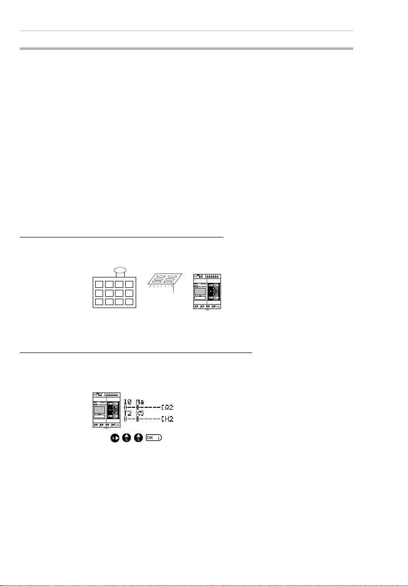
Easy Operation with an Inexpensive Controller
Ladder programming is possible directly from a LCD-type CPU Unit.
Ladder programs can be easily copied to low-cost LED-type CPU
Units by using Memory Cassettes (optional).
2
Page 27
Outline Section 1-1
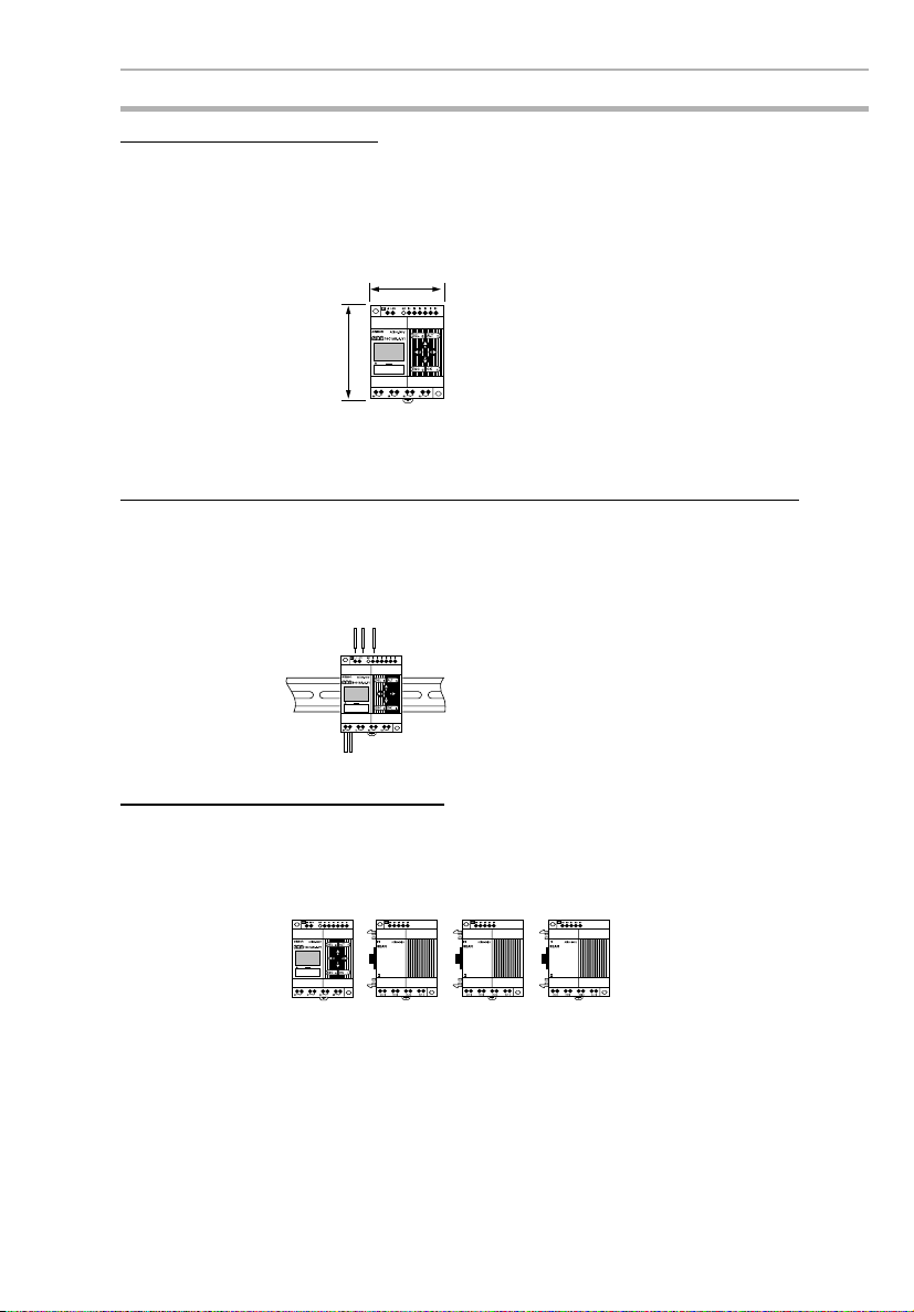
Smaller Control Panels
The ZEN is very small at 90 x 70 x 56 mm (H x W x D) and mounts
essentially anywhere.
Note Dimensions are 90 x 122.5 x 56 mm (H x W x D) for CPU Units
with 20 I/O points.
70 mm
90 mm
CPU Unit with
10 I/O points
Less Assembly and Wiring Time Required for Control Panels
Simple one-touch DIN Track mounting. Built-in timers and counters
so only power supply and I/O circuit wiring required.
Solid wires can be easily connected using only a screwdriver.
Refer to page 33.
Future System Expandability
I/O capacity can be expanded to up to 24 inputs and 20 outputs by
connecting 3 Expansion I/O Units.
Refer to page 9 and 33.
CPU Unit
12 inputs/8outputs + (4 inputs/4outputs)
Expansion I/O Units (up to 3)
´ 3
3
Page 28
Outline Section 1-1
Power Failure Countermeasures
EEPROM backs up the program and system settings data when no
power is supplied to the ZEN.
Use a Battery Unit (optional) to back up work bits, holding timers,
counters, and date/time data.
Refer to page 96.
Battery
Unit
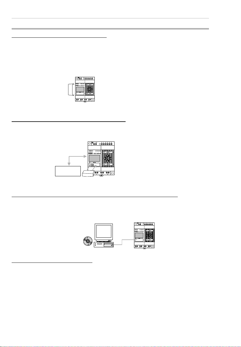
Easy Saving and Copying of Programs
Use an optional Memory Cassette to easily save and copy programs.
Refer to page 97.
Ladder program
data/settings.
Memory Cassette
Programming and Monitoring from a Personal Computer
Windows-based ZEN Support Software is available and provides a
complete simulation function.
Refer to page 99.
ZEN Support
Software
(CD-ROM)
Greater Switching Capacity
The output contacts have 8-A switching capacity (250 VAC). All contacts are independent (for CPU Units with 10 I/O points).
4
Page 29
Outline Section 1-1
Refer to page 45.
8 A max.
250 V
AC Inputs
For CPU Units with AC power supply inputs, 100 to 240 VAC can be
directly connected.
Refer to page 35.
100 to 240 VAC
LN
Easy Program Design
There are 4 different operations that can be set for bit outputs. Selfholding bits also can be easily programmed.
Refer to page 58.
Ry
-[Q0 Normal operation
-SQ0 Set operation
-RQ0 Reset operation
-AQ0 Alternate operation
MC
Circuit protector
Complicated Timers without Additional Programming
Any of the 16 timers support 4 types of operation and 3 timing
ranges.
There are also 8 built-in holding timers that hold data during power
interruptions.
Refer to page 67.
TIM
ON delay
OFF delay
One-shot pulse
Flashing pulse
0.01 to 99.99 s
1 s to 99 min 59 s
1 min to 99 h 59 min
5
Page 30
Outline Section 1-1
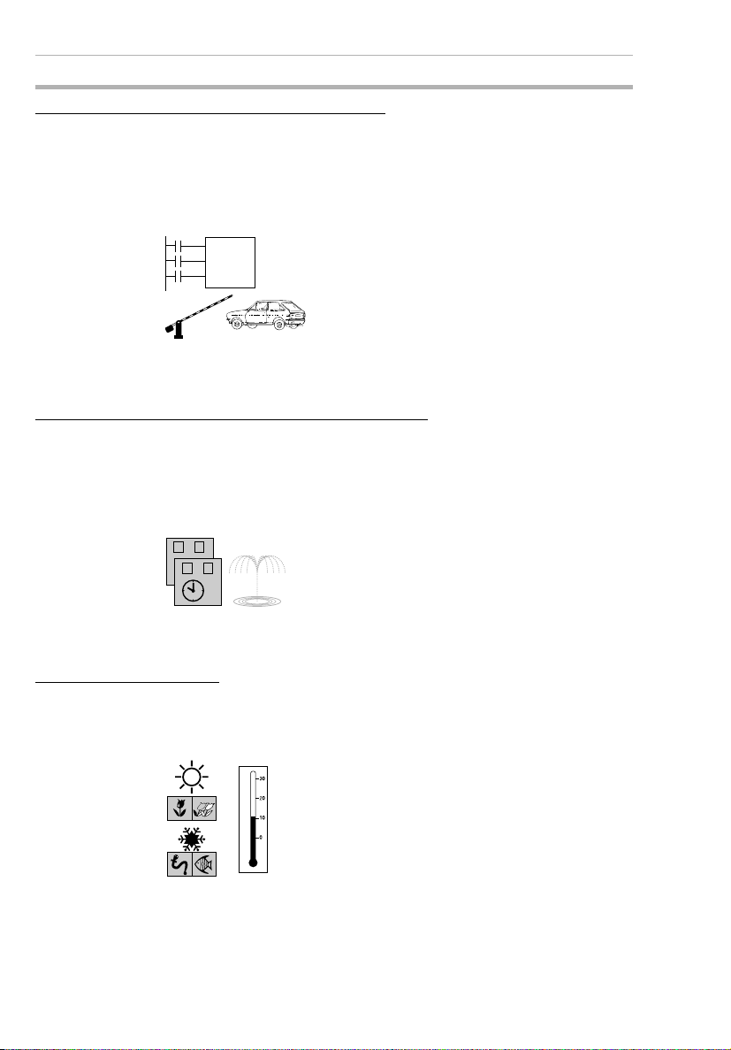
Incremental and Decremental Counters
There are 16 built-in counters that can be switched between incrementing and decrementing.
Use Comparators to enable programming multiple outputs from a
counter.
Counters: Refer to page 70.
Comparators: Refer to page 79.
C
CNT
D
R
Control number of cars entering
and leaving a car park.
Season- or Day-dependent Operating Times
CPU Units with built-in calendar and clock functions have 16 weekly
timers and 16 calendar timers. Seasonal control is possible using calendar timers and day/time control is possible with weekly timers.
Weekly timers: Refer to page 72.
Calendar timers: Refer to page 74.
MO FR
−
SA SU
−
For gardens, parks, and
recreational ponds.
Direct Analog Inputs
CPU Units with DC power supply inputs have 2 analog input points (0
to 10 V) and 4 analog comparators.
Refer to page 75.
6
Temperature control for hot
houses and tanks. Prevent
freezing of swimming pools.
Page 31

Outline Section 1-1
Easier Maintenance
Use the display function in LCD-type CPU Units to display user-set
messages, the date, time, or other data. Button switches can also be
used as input contacts. Applications include usage as a simple display operation panel.
Refer to page 82.
Longer Backlight for Dark Situations
The automatic cutout time for the backlight for LCD-type CPU Units
can be set to 2, 10, or 30 minutes, or set to operate continuously.
With the display function, the backlight can also be set to turn ON
when a message is displayed.
Refer to page 92.
Prevent Chattering and Noise-related Malfunctions
Set the input filters to extend the filter timer and prevent malfunctions.
Refer to page 90.
Filter timer
ON
7
Page 32

Features and Part Names Section 1-2
Exporting Systems Overseas
Display for LCD-type CPU Units is available in 6 languages. A Summertime function also supported.
Changing display language: Refer to page 50.
Summertime settings: Refer to page 93.
ENGLISH
JAPANESE
GERMAN
FRENCH
ITALIAN
SPANISH
Programming Security
Programs can be protected by setting a password.
Refer to page 88.
PASSWORD
RUN
3 9
0000
5 4
1-2 Features and Part Names
1-2-1 Features and System Configuration
The ZEN is small but has a wide range of functions and is easy to
use. The ZEN facilitates small-scale automatic control.
LCD-type CPU Unit Features
• Simple button-operated programming.
• Highly visible, backlit LCD.
• Adjustable automatic cutout time for the backlight.
• Adjustable contrast for the LCD screen.
• Six-language display.
• Display function for user-set messages (4 lines x 12 characters),
time, or timer, counter, or analog-converted value displays.
• Button switches allowing operation buttons to be used as input
contacts.
• Built-in weekly and calendar timers to allow simple seasonal,
daily, or time-based operation.
8
Page 33

Features and Part Names Section 1-2
LCD-type and LED-type CPU Unit Features
• Both 100 to 240-VAC and 24-VDC power supply models available.
• Built-in analog comparator for temperature control and other
analog applications (provided on CPU Units with DC power supply inputs, two analog inputs 0 to 10 V).
• Input filter settings to prevent noise-related malfunctions for both
CPU Units and Expansion I/O Units.
• Program and settings data backed up on built-in EEPROM.
• Programming using ladder diagrams.
• Password function to protect programs.
Work bits, holding
timer data, counter
data, and
date/time data will
be backed up
during long-term
power supply
interruptions if a
Battery Unit
(optional) is
mounted.
ZEN-BAT01
Battery Unit
ZEN-ME01
Memory
Cassette
Programs can be
saved and copied
by using a
Memory Cassette
(optional).
LCD/LED-type
CPU Unit
With CPU Units with 10 I/O points, up to 18 inputs and 16 outputs are possible if 3
Expansion I/O Units are connected.
With CPU Units with 20 I/O points, up to 24 inputs and 20 outputs are possible if 3
Expansion I/O Units are connected.
Expansion I/O Units (up to 3 can be connected)
Personal computer
connecting cable
ZEN-SOFT01-V3
ZEN Support
Software
Relay outputs have large a switching capacity
(8A at 250 VAC), while transistor outputs can
switch 0.5 A at 24 VDC.
All outputs have independent contacts except
for CPU Units with 20 I/O points, which have
one common for each 2 outputs for 4 of the 8
outputs.
Programs can be created, edited, saved, and printed,
and operation can be simulated using the ZEN
Support Software (optional).
9
Page 34

Features and Part Names Section 1-2
1-2-2 Part Names
LCD-type CPU Units with 10 I/O Points
(with LCD and Operation Buttons)
Power supply Inputs Outputs Input
100 to 240
VAC, 50/60
Hz
24 VDC 24 VDC Yes ZEN-10C1DR-
100 to
240 VAC
6 Relays 4 Yes No Yes ZEN-10C1AR-
Not
isolated
Transistors
filter
Analog
inputs
Calen-
dar/time
Model number
A-V1
D-V1
ZEN-10C1DTD-V1
Left Side
Battery Unit connector
(Remove the seal to
connect the Battery Unit.)
Power supply
terminals
LCD
Front
Input terminals
Operation
buttons
ZEN Support Software connector
ZEN Support Software connector
(also used for Memory Cassette.)
(also used for Memory Cassette.) Remove this cover to
Output terminals
Remove this cover to
connect Expansion Unit.
connect Expansion Unit.
Right Side
Expansion Unit
connector cover.
10
Page 35

Features and Part Names Section 1-2
LCD-type CPU Units with 20 I/O Points
(with LCD and Operation Buttons)
Power supply Inputs Outputs Input
100 to 240
VAC, 50/60
Hz
100 to
240 VAC
12 Relays 8 Yes No Yes ZEN-20C1AR-
Not
isolated
24 VDC 24 VDC Yes ZEN-20C1DR-
Transistors
filter
Analog
inputs
Calen-
dar/time
Model num-
ber
A-V1
D-V1
ZEN-20C1DTD-V1
Left Side
LCD
Battery Unit connector
(Remove the seal to
connect the Battery Unit.)
t
n
o
r
F
Power supply
terminals
20C1AR-A-V1
Input terminals
ZEN Support Software connector
(also used for Memory Cassette.)
I6I7I8I9IaI
Q
4
Q6Q5Q
Output terminals
Operation
buttons
7
Right Side
b
Expansion Unit
connector cover.
Remove this cover to
connect Expansion Unit.
11
Page 36

Features and Part Names Section 1-2
LED-type CPU Units with 10 I/O Points
(without LCD/Operation Buttons)
The ZEN is also available in an LED type that provides full operating
functionality, but no direct programming input. The ZEN Support Software or a Memory Cassette containing a program is required.
Power supply Inputs Outputs Input
100 to 240
VAC, 50/60
Hz
24 VDC 24 VDC Yes ZEN-10C2DR-
100 to
240 VAC
6 Relays 4 Yes No No ZEN-10C2AR-
Not
isolated
Transistors
filters
Analog
inputs
Calen-
dar/time
Model number
A-V1
D-V1
ZEN-10C2DTD-V1
Indicators
Left Side Front
Battery Unit connector
(Remove the seal to
connect the Battery
Unit.)
Name Color Meaning
POWER Green Lit Power supplied
RUN Green Lit Operating (RUN)
ERROR Red Lit Error
Power supply
terminals
Personal computer
connector (also used for
Memory Cassette.)
LED indicators
Not lit No power
Not lit Stopped (STOP)
Not lit Normal
Input terminals
Output ter minals
Right Side
Expansion I/O Unit
connector cover
Remove this cover to
connect Expansion I/O Unit.
12
Page 37

Features and Part Names Section 1-2
LED-type CPU Units with 20 I/O Points
(without LCD/Operation Buttons)
Power supply Inputs Outputs Input
filters
100 to 240
VAC, 50/60
Hz
100 to
240 VAC
12 Relays 8 Yes No No ZEN-20C2AR-
Not
isolated
24 VDC 24 VDC Yes ZEN-20C2DR-
Transistors
Analog
inputs
Calen-
dar/time
Model num-
ber
A-V1
D-V1
ZEN-20C2DTD-V1
Left Side Front
Battery Unit
connector
(Remove the
seal to connect
the Battery Unit.)
Indicators
Right Side
Power supply
terminals
20C2AR-A-V1
LED indicators
Input terminals
Q4Q6Q5Q
Personal computer
connector (also used for
Memory Cassette.)
Output ter minals
I6I7I8I9IaI
7
b
Remove this cover to
connect Expansion I/O Unit.
Name Color Meaning
POWER Green Lit Power supplied
Not lit No power
RUN Green Lit Operating (RUN)
Not lit Stopped (STOP)
ERROR Red Lit Error
Not lit Normal
Expansion I/O Unit
connector cover
13
Page 38

Features and Part Names Section 1-2
Differences between LCD- and LED-type CPU Units
Item LCD type LED type
AC power
supply
Program editing, parameter
settings, operation monitoring
Operating mode switching Yes (Also possible with ZEN
Calendar and clock function Yes No
Bits Input, output,
Settings Display language Yes (Also possible with ZEN
Expansion I/O Unit connection Yes Yes
Memory
Cassette
functions
Battery Unit connection Yes Yes
ZEN Support Software connection
work, holding bits
Timer, holding
timer, counter
Weekly timer,
calendar timer
Analog comparator
Timer/counter
comparator
Button switches Yes Yes
Display function Yes No
Backlight cutout
time
Input filters Yes (Also possible with ZEN
Password Yes (Also possible with ZEN
ZEN to Memory
Cassette transfer
Memory Cassette to ZEN
transfer
Memory Cassette initialization
Yes (Also possible with ZEN
Support Software.)
Support Software)
Ye s Ye s
Ye s Ye s
Ye s N o
No Yes No Yes
Yes Yes (ZEN Support Software
Support Software.)
Yes (Also possible with ZEN
Support Software.)
Support Software.)
Support Software.)
Ye s N o
Yes Yes (Automatic transfer when
Ye s N o
Ye s Ye s
DC power
supply
AC power
supply
Yes (ZEN Support Software
required.)
Yes (ZEN Support Software
required.)
required.)
-
-
Yes (ZEN Support Software
required.)
Yes (ZEN Support Software
required.)
power is turned ON.)
DC power
supply
14
Page 39
Features and Part Names Section 1-2
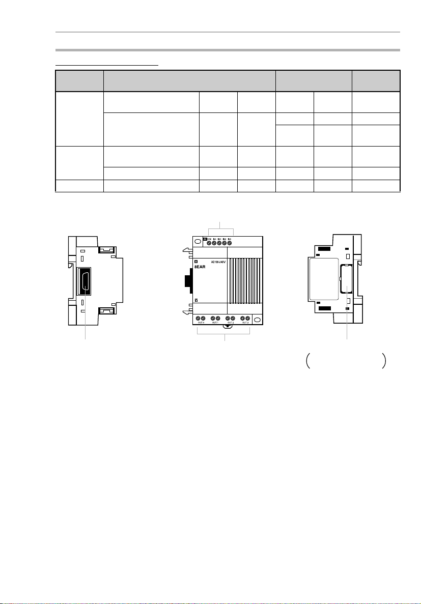
Expansion I/O Units
No. of I/O
Points
8 I/O 100 to 240 VAC, 50/60 HzIsolated 4 Relays 4 ZEN-8EAR
24 VDC Isolated 4 Relays 4 ZEN-8EDR
4 inputs 100 to 240 VAC, 50/60 HzIsolated 4 --- --- ZEN-4EA
24 VDC Isolated 4 --- --- ZEN-4ED
4 outputs --- --- --- Relays 4 ZEN-4ER
Inputs Outputs Model
Transistors
4 ZEN-8EDT
Left Side
Expansion Unit connector Output terminals
Front
Input terminals
Right Side
Expansion Unit connector cover.
Remove this cover to
connect Expansion I/O Unit.
15
Page 40

Display Screen and Basic Operations Section 1-3
1-3 Display Screen and Basic Operations
The display screen for the LCD-type CPU Units and the operations of
the buttons are shown below.
LCD
Icon Meanings
ESC Button OK Button
RUN ERR
▲▼
Icon Meaning
RUN Displayed while in RUN mode.
ERR Indicates an error.
▲
▼
Displayed when there is a higher-level menu or ladder
program line than the one currently displayed.
Displayed when there is a lower-level menu or ladder
program line than the one currently displayed.
Displayed when a password has been set.
ALT ButtonDEL Button
Cursor
Buttons
16
Page 41

Display Screen and Basic Operations Section 1-3
Operation Button Names and Operations
Button Function
Menus Writing ladder program Setting parameters Button switch
DEL --- Deletes inputs, outputs, con-
ALT --- Switches between normally
Up Moves the cur-
Down B2 ON
Left --- Moves the cursor right and
Right B4 ON
ESC Returns to the
OK Selects the
sor up and
down.
previous
screen.
menu item at
the cursor
position.
nection lines, and blank
lines.
open and normally closed
conditions.
Changes to connection line
write mode.
Inserts a line.
Moves the cursor up and
down.
Selects bit types and functions.
left.
Cancels the setting and
returns to the previous operation.
Confirms the setting. Confirms the setting. B1 ON
--- B6 ON
--- B7 ON
Moves the cursor up
and down.
Changes numerals
and parameters.
Moves the cursor
right and left.
Cancels the setting
and returns to the
previous operation.
(See85.)
B5 ON
B3 ON
B0 ON
17
Page 42

Display Screen and Basic Operations Section 1-3
1-3-1 Screens
STOP Mode
When power is turned ON
When Expansion I/O Unit
is connected.
Display Function Screen
(Userspecified
message)
Note: The display will be
blank if the display function is
not being used.
RUN Mode
When power is turned ON
When Expansion I/O Unit
is connected.
Display Function Screen
(Userspecified
message)
Note: The display will be
blank if the display function is
not being used.
STOP Mode
PROGRAM
RUN
PARAMETER
SET CLOCK
PARAMETER
SET CLOCK
LANGUAGE
OTHER
RUN Mode
MONITOR
STOP
PARAMETER
SET CLOCK
RUN
PARAMETER
SET CLOCK
LANGUAGE
OTHER
RUN
18
Page 43

Display Screen and Basic Operations Section 1-3
Display Screens
Main Screen
Day
When One or More Expansion I/O Units Are Connected
Operating mode
Time (min:s)
Day display
SU: Sunday
MO: Monday
TU: Tuesday
WE: Wednesday
TH: Thursday
FR: Friday
SA: Saturday
CPU input bit (I) status
( : OFF/ : ON)
I0 I1 I2 I3 I4 I5
CPU output bit (Q) status
(@: OFF/ : ON)
@@@@
Q0 Q1 Q2 Q3
Expansion I/O Unit input bit (X) status
( : OFF/ : ON)
X0 X1 X2 X3 X4 X5 X6 X7 X8 X9
Xa Xb
Expansion I/O Unit output bit (Y) status
(@: OFF/ : ON)
@@@@@@@@@@
Y0 Y1 Y2 Y3 Y4 Y5 Y6 Y7 Y8 Y9
CPU Units
with 10 I/O
points
CPU Units
with 10 I/O
points
@@@@
Q0 Q1 Q2 Q3
@@
Ya Yb
I0 I1 I2 I3 I4 I5
Ia Ib
CPU Units
I6 I7 I8 I9
@@@@
Q4 Q5 Q6 Q7
Note: The display depends
on the number of input
points on the connected
Expansion I/O Units.
Note: The display depends
on the number of output
points on the connected
Expansion I/O Units.
with 20 I/O
points
CPU Units
with 20 I/O
points
19
Page 44
Display Screen and Basic Operations Section 1-3
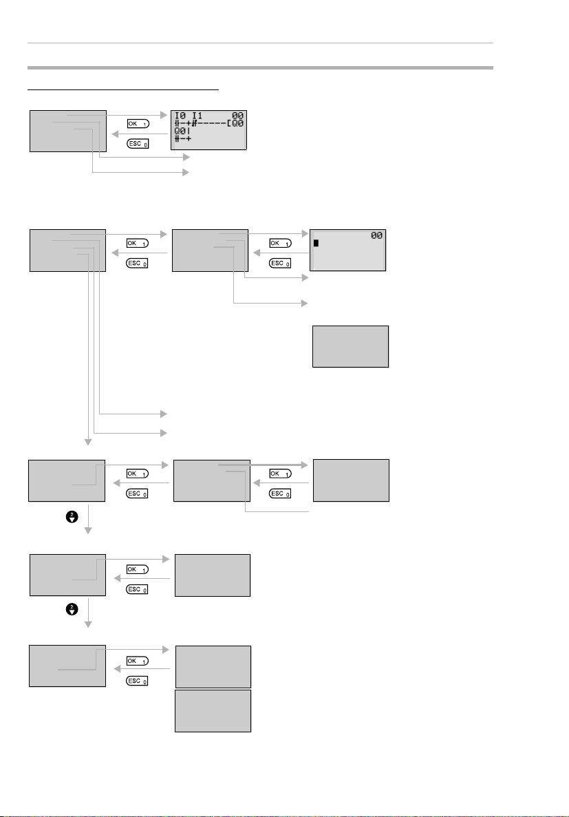
Menu Screen Configuration
RUN Mode
MONITOR
STOP
PARAMETER
SET CLOCK
RUN
▼
STOP Mode Ladder Program Edit Screen
PROGRAM
RUN
PARAMETER
SET CLOCK
▼
Date and Time Settings (Refer to page 51.)
PROGRAM
RUN
PARAMETER
SET CLOCK
▼
Display Language Settings (Refer to page 50.)
RUN
PARAMETER
SET CLOCK
LANGUAGE
▲▼
Ladder Monitor Screen
The ON/OFF status of input bits can be checked by
monitoring the ladder program.
Switches to STOP mode.
The operation status of the timers, counters, and analog
comparators can be monitored and the settings changed
during operation. Refer to page 25.
EDIT PROG
DELETE PROG
C ASSETTE
(Refer to page 23.)
Creates and edits
ladder program.
Deletes ladder program and
parameters.
Memory Cassette Operation
(Refer to page 97.)
SAVE
LOAD
ERASE
Note: Displayed only when a Memory
Cassette is mounted.
Transfers programs
between ZEN and
the Memory Cassette
and initializes the
Memory Cassette.
Switches to RUN mode.
Changes the settings for timers, counters, and analog comparators.
(Refer to page 28.)
SET CLOCK
SUMMER TIME
LANGUAGE
ENGLISH
The display language can be changed.
English, Japanese, German, French, Italian, and
Spanish
SET CLOCK
yy/mm/dd
00/01/01
00:03(SA)
Set when shipping to countries that
use summer time. (Refer to page 93.)
Sets the date and
time.
Other Settings
PARAMETER
SET CLOCK
LANGUAGE
OTHER
▲
20
PASSWORD
CONTRAST
BACK LIGHT
INPUT FILTER
INPUT FILTER
MODEM INI
NODE NO
SYSTEM INF
Other settings can be made. Refer to the following
page for details.
▼
▲
Page 45

Display Screen and Basic Operations Section 1-3
Other Submenus
PASSWORD
CONTRAST
BACK LIGHT
INPUT F ILT ER
▼
INPUT FILTER
MODEM INI
NODE NO
SYSTEM IN F
▲
Setting Passwords (Refer to page 88.)
PASSWORD
Set a password when you want to protect
programs from being read. The password
0000
setting range is 0000 to 9999.
Adjusting Contrast (Refer to page 93.)
CONTRAST
Adjust the contrast when the LCD screen is
faint and difficult to read or when it is too dark
@@
to read. There are 5 contrast levels.
Changing Cutout Time for Backlight (Refer to page 92.)
BACKLIG HT
Set the automatic cutout time for the backlight
in the LCD screen.
2min
2 min, 10 min, 30 min, Always ON
Setting Input Filters (Refer to page 90.)
INNER
EXP1
EXP2
EXP3
Set the input filters to ON or OFF for the CPU
Unit or Expansion I/O Units. Set to ON when
noise or chattering may affect operation.
“EXP1” to “EXP3” will be displayed depending
on the number of Expansion I/O Units
connected.
Do not use. For future system expansion.
Setting Node Number (Refer to page 99.)
NODE NO
Set to the node number specified using the
ZEN Support Software.
0
Reading System Information (Refer to page 94.)
U02.00
030218
INT:I06004
E X1:I04004
EX2 :I0 4000
EX3 :I00004
RMT:I00000
LCD: YES
▲▼
RMT:I00000
LC D:YES
RT C:YES
ADC:YES
▲
Read system information, such as the CPU
Unit software version or the date it was
created, the number of I/O points on the CPU
▼
Unit or the Expansion I/O Units, and whether or
not LCD, RTC, or analog input functions are
supported.
21
Page 46

Display Screen and Basic Operations Section 1-3
1-3-2 Basic Operation
Menu Selection Example
Main menu
display
RUN
PARAMETER
SET CLOCK
LANGUAGE
▲▼
Flashing cursor
Use the Up/Down Buttons to move the cursor.
LANGUAGE
ENGLISH
Highlighted cursor
LANGUAGE
ENGLISH
Flashing cursor
LANGUAGE
GERMAN
LANGUAGE
SET?
OK /ESC
GERMAN
RUN
PARAMETER
KALENDER
SPRACHE
▲▼
Press the OK Button to select the flashing
menu. The settings will flash on a reversed
display.
Press the OK Button to change from a highlighted cursor to a flashing cursor. Settings
can now be changed.
Use the Up/Down Buttons to change the setting.
Use the Up Button to select GERMAN.
A confirmation message will be displayed
asking if you want to change to German display.
Press the OK
Button to
change from
English to
German.
RUN
PARAMETER
SET CLOCK
LANGUAGE
▲▼
Press the
ESC Button to
cancel the
change and
return to the
previous
screen.
22
Page 47

Display Screen and Basic Operations Section 1-3
Example Operation in the Ladder Program Edit Screen
Select
Program/
Edit.
Line No.
at
Highlighted cursor
cursor
The highlighted cursor will appear in the initial write position. During highlighted cursor
display, the cursor can be moved to the input
or output write positions.
Up/Down Buttons: Move the highlighted cursor up and down.
Left/Right Buttons: Move the highlighted cursor Left/Right.
Press the OK Button at the input write position to display the input default setting IO and
the normally open condition symbol. “I” will
flash.
• Flashing Cursor at the I Position
Up/Down Buttons: Change the bit type.
Right Button: Moves the flashing cursor
to the right.
OK Button: Sets the bit type and moves
the flashing cursor to the bit address
position.
• Flashing Cursor at the 0 Position
Up/Down Buttons: Change the bit
address.
OK Button: Completes the writing of the
bit.
• Switching between Normally Open and
Normally Closed Conditions
You can use the ALT Button to switch
between the N.O. and N.C. conditions,
regardless of the position of the flashing
cursor.
When the first input has been written, the
highlighted cursor moves to the next input
position.
Use the above procedure to enter program
input conditions in series.
When writing serial inputs, the connecting
line between inputs is drawn automatically.
23
Page 48

Display Screen and Basic Operations Section 1-3
Press the ALT Button with the highlighted
cursor in the input writing position to change
the cursor to a flashing left arrow to enable
connecting lines to be drawn.
Up/Down Buttons: Draw vertical connecting
lines.
Left/Right Buttons: Draw horizontal connecting lines.
Press the Right Button twice to draw a line to
the output bit. The cursor will change to a
▼
▼
▼
▼
▼
highlighted cursor at the output bit write position.
Press the OK Button at the output bit write
position to display the default output Q0. Q
will flash.
• Flashing Cursor at the Q (Bit Type) Position
Up/Down Buttons: Change the type of
output
Right/Left Buttons: Move the flashing
cursor.
OK Button: Sets the bit type and moves
the flashing cursor to the bit address
position.
• Flashing Cursor at the (Additional Output Function) Position
Up/Down Buttons: Selects the additional
output function
OK Button: Sets the additional output
function and moves the flashing cursor
to the bit address position.
• Flashing Cursor at the 0 (Bit Address)
Position
Up/Down Buttons: Select the bit address
OK Button: Completes the output write.
Press the OK Button to complete the bit write
01
and to move the highlighted cursor to the first
input position ON the next line.
24
Press the ESC Button to complete the writing
of the ladder program and to return to the
menu screen.
Page 49

Display Screen and Basic Operations Section 1-3
Example Parameter Settings Screen Operation
Select
Parameters
on menu
screen.
(1) Selecting Parameters to Display
When Parameter is selected, the parameter
settings are displayed.
Press the OK Button to change the highlighted cursor to a flashing cursor.
/
/
(2) Setting and Changing Parameters
Use the Up/Down Buttons to select another
timer.
When multiple parameters of the same type
have been selected, use the Up/Down But-
tons to scroll through the numbers.
Press the Left Button to switch to another
type, move the flashing cursor to the bit type
position and use the Up/Down Buttons to
select the bit type.
Move the flashing cursor to the bit type position and use the Up/Down Buttons to select
another bit type.
Use the Left/Right Buttons to move the highlighted cursor to the parameter to be set.
Press the OK Button to confirm the set position. The cursor will change to a flashing cursor.
/
Use the Up/Down Buttons to set the parameter.
Press the OK Button to confirm the setting.
25
Page 50

Display Screen and Basic Operations Section 1-3
Use the Left/Right or Up/Down Buttons to
move the highlighted cursor to the parameter
to be set.
Press the OK Button to confirm the set position. The cursor will change to a flashing cursor.
Use the Left/Right Buttons to select the digit
to be set.
Use the Up/Down Buttons to change the
value of each digit.
Press the OK Button to confirm the setting.
Press the ESC Button to complete the settings.
Note If the ESC Button is pressed while ladder program or parameter
settings are being input, the input to that point will be canceled
and the settings will return to the original settings.
26
Page 51

Memory Areas Section 1-4
1-4 Memory Areas
I/O, Work, and Internal Holding Bits
Name Ty pe Bit
CPU Unit
input bits
Expansion
I/O Unit
input bits
Button
switches
Analog
comparator bits
Comparator bits
CPU Unit
output bits
Expansion
I/O Unit
output bits
Work bits M 0 to f 16 Can only be used within the program.
Holding
bits
addresses
I 0 to 5 6 CPU Units
0 to b 12 CPU Units
X 0 to b 12 Reflect the ON/OFF status of the input
B 0 to 7 8 Turn ON when the operation buttons
A 0 to 3 4 Output the comparison result for ana-
P 0 to f 16 Compare the present value of timers
Q 0 to 3 4 CPU Units
0 to 7 8 CPU Units
Y 0 to b 12 Output the ON/OFF status of the output
H 0 to f 16 Same as for work bits however the
No.
of
bits
with 10 I/O pts
with 20 I/O pts
devices connected to the Expansion
I/O Unit input terminals.
are pressed in RUN mode. Can only be
used for LCD-type CPU Units.
log inputs. Can only be used for models
with a 24-VDC power supply.
(T), holding timers (#), and counters
(C), and outputs the comparison result.
with 10 I/O pts
with 20 I/O pts
bits to the outputs devices connected
to the Expansion I/O Unit.
Cannot output to an external device.
holding bits maintain ON/OFF status
when power is turned OFF.
Function Ladder
Reflect the ON/OFF
status of the input
devices connected to
the CPU Unit input terminals.
Output the ON/OFF
status of the output
bits to the outputs
devices connected to
the CPU Unit.
programs
N.O./N.C.
inputs
N.O./N.C.
inputs
Outputs
(See
note.)
Page
29
29
85
75
79
29
29
-
-
Note The following additional functions can be selected for bit outputs.
Execution condition
[ Normal output Turns ON or OFF according to the ON/OFF status of the execution condition.
S Set Holds ON status after the execution condition turns ON once.
R Reset Holds OFF status after the execution condition turns ON once.
A Alternate Alternates between ON and OFF whenever the execution condition turns ON
(input latch operation).
Bit address
Bit type
Additional function ([, S, R, A)
27
Page 52

Memory Areas Section 1-4
Timers and Counters
Name Ty pe Bit
Timer T 0 to f 16 Can be switched between ON delay,
Holding
timer
Counter C 0 to f 16 Reversible counters that can be
Weekly
timer
Calendar timer
addres
ses
# 0 to 7 8 Holds the present value during
@ 0 to f 16 Can turn ON or OFF during a speci-
0 to f 16 Can turn ON or OFF during a speci-
Note 1. The above memory areas are smaller for pre-V1 CPU Units.
2. Timers can switch between operations. Refer to page 59.
X ON
delay
■
OFF
delay
O One-shot Turns ON the timer bit for the set period when the trigger input changes from OFF
F Flashing
pulse
Times down while the trigger input is ON and turns ON the timer bit when the set
time is reached.
Turns ON the timer bit while the trigger input is ON, starts timing down when the
trigger input turns OFF, and turns OFF the timer bit when the set time is reached.
to ON only.
Timer bit repeatedly turns ON/OFF at set intervals while the trigger input is ON.
No. of
tim-
ers/coun
ters
Function Use in lad-
OFF delay, one-shot, and flashing
pulse operation.(See note.)
counting even if the trigger input or
power supply is turned OFF. Continues the timing when the trigger input
or power supply is turned ON again.
incremented and decremented.
fied day or time period.
fied date period.
der pro-
grams
N.O./N.C.
condition
Page
67
67
70
72
74
Display Bits
Name Typ e Bit
Display D 0 to f 16 Display user-set character
addresses
Note The above memory area is smaller for pre-V1 CPU Units.
D
Display No.
Function switching
No.
of
bits
strings, times, timer present values, counter present values, or
analog-converted values.
Function Use in lad-
Function switching
D Display
C Clear display
- - -(System software
Ver. 1.10 or later)
28
der pro-
Page
grams
Output 82
Page 53

Allocating I/O Bit Numbers Section 1-5
1-5 Allocating I/O Bit Numbers
For CPU Units with 10 I/O points, the input bit addresses I0 to I5 and
output bit addresses Q0 to Q3 are always allocated to the CPU Unit.
For CPU Units with 20 I/O points, the input bit addresses I0 to Ib and
output bit addresses Q0 to Q7 are always allocated to the CPU Unit.
Up to 3 Expansion I/O Units can be added and input bit addresses X0
to Xb and output bit addresses Y0 to Yb are allocated in the order the
Units are connected.
Connection Example for 4-point Expansion Input Unit, 4-point
Expansion Output Unit, and 8-point Expansion I/O Unit
■
CPU Units with 10 I/O Points
Input bit
address
Output bit
address
Input bit
address
Output bit
address
I0 I1 I2 I3 I4 I5 X0 X1 X2 X3
IN0IN1IN 2IN3IN4IN5IN0IN 1IN2IN
CPU Unit
(10 I/O points)
OUT 0OUT 1OUT 2OUT
3
Expansion
I/O Unit 1
(4 inputs)
Expansion
3
I/O Unit 2
(4 outputs)
OUT 0OUT 1OUT 2OUT 3OUT 0OUT 1OUT 2OUT
Q0 Q1 Q2 Q3 Y0 Y1 Y2 Y3 Y4 Y5 Y6 Y7
■
CPU Units with 20 I/O Points
I0
I1 I2 I3 I4 I5
IN0IN1IN2IN3IN4IN
OUT 0OUT 1OUT 2OUT
Q0 Q1Q2 Q3 Y0 Y1 Y2 Y3 Y4Y5 Y6 Y7
I6 I7 I8 I9 Ia Ib
IN6IN7IN8IN9INaIN
5
CPU Unit
(20 I/O points)
OUT 4OUT 5OUT 6OUT
3
Q4 Q5Q6 Q7
X0 X1 X2 X3X4X5 X6 X7
IN0IN1IN2IN
b
Expansion
I/O Unit 1
(8 I/O points)
7
OUT 0OUT 1OUT 2OUT
IN0IN1IN2IN
3
Expansion
I/O Unit 2
(8 I/O points)
OUT 0OUT 1OUT 2OUT
3
X4
IN0IN1IN2IN
Expansion
I/O Unit 3
(8 I/O points)
X8
X9 Xa Xb
IN0IN 1IN2IN
3
Expansion
I/O Unit 3
(4 inputs)
3
X5 X6 X7
3
3
3
Note When an Expansion I/O Unit that does not have both inputs and
outputs, such as the 4-point Input Unit and the 4-point Output
Unit shown in the above diagram, the unused bit addresses are
not allocated to that Unit and are used for the next Unit.
29
Page 54

Preparations for Operation Section 1-6
1-6 Preparations for Operation
Mount ZEN to Control Panels
The ZEN can be mounted to either a
DIN Track or directly onto the surface
of the control panel. Refer to page 32.
Connect Power Supply, Input, and Output
Devices
Wire the ZEN to the power supply, input, and
output devices. Refer to page 33.
Make Initial Settings
Make the settings required before
programming, such as date, time, and
display language. Refer to pages 50
and 51.
Write Program
Input the ladder program, including
timers, counters, and other parameters.
Use the ZEN Support Software when
using the LED-type CPU Units (without
LCD or operation buttons.) Refer to
page 52.
Check Program Execution
Perform trial operation before starting actual
operation and check that the system is
operating correctly. Refer to page 62.
DIN Track
Powe r
supply
Output
LCD-type CPU
Unit
Load
Load
Load
ON OFF
Load
Operation
buttons
Inputs
Save Program
Debugged programs and all parameters
should be saved to a Memory Cassette
or ZEN Support Software to prevent
loss of the data. Refer to page 97.
Actual Operation
30
ZEN-ME01
Memory Cassette
Page 55

SECTION 2
Installation and Wiring
This section explains how to mount and wire the ZEN CPU Units and Expansion I/O Units.
2-1 Mounting . . . . . . . . . . . . . . . . . . . . . . . . . . . . . . . . . . . . . . . . . . . . . . . . . . . . 32
2-1-1 Installation Method . . . . . . . . . . . . . . . . . . . . . . . . . . . . . . . . . . . . 32
2-1-2 Connecting Expansion I/O Units . . . . . . . . . . . . . . . . . . . . . . . . . . 33
2-2 Wiring . . . . . . . . . . . . . . . . . . . . . . . . . . . . . . . . . . . . . . . . . . . . . . . . . . . . . . 33
31
Page 56

Mounting Section 2-1
2-1 Mounting
2-1-1 Installation Method
Always mount the ZEN inside a control panel. The ZEN can either be
mounted to the surface of the control panel or onto DIN Track.
Orientation
Do not mount the ZEN in any orientation other than the one shown in
the following diagram.
To p
Bottom
Mounting to DIN Track
1 Pull down the hook
on the bottom of the
ZEN.
2 Hang the slot at the
back of the ZEN on to
the top of the DIN
Tra c k.
3 Attach the ZEN to the
DIN Track.
4 Push up the locking
hook on the bottom of
the ZEN to lock the
ZEN in place.
Mounting Inside a Control Panel
Use M4 screws to mount the ZEN.
B
A
Tw o, M 4
4.5
5.5
Mounting Dimensions (Unit: mm)
Unit A B
CPU Unit CPU Units with 10 I/O points 60 80
CPU Units with 20 I/O points 112.5 80
Expansion
I/O Unit
Units with 8 I/O points 60 80
Units with 4 inputs
Unit with 4 outputs
32
Page 57

Wiring Section 2-2
2-1-2 Connecting Expansion I/O Units
Up to 3 Expansion I/O Units can be connected.
1 Remove the Expansion Unit connector cover
on the side of the CPU Unit.
Insert a flat-blade
screwdriver or
similar tool and
remove the cover.
Note 1. Do not remove the Expansion Unit connector cover on the right
edge of the connected Expansion Unit.
2. Be careful when inserting the screwdriver that you do not insert it
too far and damage the base or the elements.
2-2 Wiring
General Wiring Precautions
External Wiring
Do not run ZEN I/O lines in the same duct or conduit as power lines.
■
Hanging Ducts
Leave at least 300 mm between the power cables and the I/O or control wiring, as shown in the following diagram.
2 Line up the connectors on the Expansion I/O Unit with the
connectors on the CPU Unit and join.
Make sure the connectors are lined up and push
the Expansion I/O Unit and the CPU Unit
together.
I/O lines
Control cables and
power lines
Power cables
300 mm min.
300 mm min.
33
Page 58

Wiring Section 2-2
■
Floor Ducts
Leave at least 200 mm between the wiring and the top of the duct, as
shown in the following diagram.
I/O lines
■
Conduits
Control cables and
power lines
Power cables
Metal plate (iron)
200 mm min.
Separate the ZEN I/O lines, power and control lines, and power
cables, as shown in the following diagram.
Control cables and
I/O lines
power lines
Power cables
Do not run ZEN I/O lines in the same duct or conduit as power lines.
Connectable Wires
• A terminal block designed for solid wires is used. Use solid wires
when wiring.
Solid wires Stranded wires Straight terminals
One-line connection
Two-line connection
0.2 to 2.5 mm
0.2 to 0.75 mm
2
0.2 to 2.5 mm
(Equivalent to AWG 24 to 14.)
2
0.2 to 0.75 mm
(Equivalent to AWG 24 to 19)
2
2
0.25 to 2.5 mm
0.25 to 0.75 mm
2
2
34
• Strip the sheath back 6.5 mm.
6.5 mm
Page 59

Wiring Section 2-2
• Twisted wires can cause shorts so never directly connect twisted
wires. Always connect a straight crimp terminal if using twisted
wires.
Insulated
sleeve
Bar terminal
• Use a flat-blade screwdriver to tighten the terminal block screws.
Wiring Power Supply and Input Lines
AC Power Supplies
!WARNING Do not connect the isolated side (L) and the grounded side (N) in
reverse. Wire the L side to the AC input circuit.
!Caution Tighten the AC power supply terminals to a torque of 0.5 to
0.6 N·m. Loose screws can result in fire or faulty operation.
■
CPU Units with 100 to 240-VAC Power Supplies
• To prevent voltage drops due to starting currents and inrush currents in other devices, wire the ZEN power supply circuit separately from other power circuits.
• When using more than one ZEN, to prevent voltage drops due to
inrush current and circuit-breaker malfunctions, it is recommended that each one is wired separately.
• To prevent the influence of noise from power lines, twist the
power lines. Wiring via a 1-to-1 isolation transformer is also
effective.
• Use wires that are thick enough to allow for voltage drops and
current variations within the allowable range.
AC power supply
Circuit
protector
Isolation
transformer
CPU Unit (AC power supply type)
Input device
Input device
Expansion I/O Unit (AC input type)
35
Page 60

Wiring Section 2-2
CPU Units with 10 I/O Points (V1 and Pre-V1 Models)
100 to 240 VAC, 50/60 Hz, 30 VA
LN
Circuit
protector
CPU Unit with
10 I/O points
Input device
ON
OFF
³ 80 V
£ 25 V
CPU Units with 20 I/O Points
LN
Circuit
protector
ON
OFF
³ 80 V
£ 25 V
NC
CPU Unit with
20 I/O points
■
Expansion I/O Units
LN
Circuit
Circuit
protector
protector
Expansion I/O Unit (AC input type)
Input device
I6NC I7 I8 I9 Ia IbI5I0 I1 I2 I3 I4
ON
OFF
³ 80 V
£ 25 V
Note 1. Observe the power supply polarity when wiring the power supply
and the input circuits. The input signals cannot be read if the polarity is incorrect.
2. Include a circuit protector or breaker for the ZEN in the power supply circuit.
3. There are no restrictions on the polarity of the inputs on the Expansion I/O Units.
4. A two-wire sensor cannot be connected directly to the AC input.
To connect a two-wire sensor, attach an external bleeder resistance in the way shown below.
36
Page 61

Wiring Section 2-2
• Example: Connecting to a CPU Unit
Two-wire
sensor
Two-wire
sensor
L
I0 to I5
R
N
300k330k
51k
Internal
circuit
• Example: Connecting to an Expansion I/O Unit
83k
IN
R
COM
4.7k
Internal
circuit
a) Use a resistance that satisfies both of the following condi-
tions.
R (W) £
Max. OFF-voltage for AC input (25 VAC)
Sensor’s max. leakage current
R (W) £
Voltage supplied to sensor
Min. current for which the
sensor’s OFF residual voltage is
less than 25 V
b) Because of heat generation, use a resistor with at least the
following wattage.
(
Voltage supplied
to sensor)
P (W) ³
2
´ 3 (allowance factor)
Resistance value
37
Page 62

Wiring Section 2-2
DC Power Supplies
■
CPU Units with 10 I/O Points
!Caution Be sure to connect COM terminal before turning ON power. The
un-connecting COM terminal or the wiring change after turning
ON power may cause malfunction.
Connecting a Negative Common (V1 CPU Units)
24 VDC, 6.5 W
CPU Unit with
10 I/O points
COM
Note: Supply power to the COM
terminal at the same time as
to the power supply terminal.
Input device
Connecting Analog Input Devices (Input Range: 0 to 10 V)
to Input Terminals I4 and I5
24 VDC, 6.5 W
DC power supply
Note: When connecting an analog
input device, always connect
the negative side to the COM
COM
terminal.
38
CPU Unit with
10 I/O points
Connecting Positive Common (V1 CPU Units Only)
24 VDC, 6.5 W
COM
CPU Unit with
10 I/O points
Note: 1. If a positive common is used,
Input device
analog input devices cannot
be connected to I4 and I5.
2. Supply power to the COM
terminal at the same time as
to the power supply terminal.
Page 63

Wiring Section 2-2
Connecting to Pre-V1 CPU Units
24 VDC, 6.5 W
+
–
CPU Unit
Note: With pre-V1 CPU Units,
the negative side of the
power supply circuit is
connected internally as
Input device
the common for the
input circuits. Input
circuits cannot be
connected with a
positive common; they
will not work.
Connecting Analog Inputs (Input Range: 0 to 10 V)
to Input Terminals I4 and I5 (Pre-V1 CPU Units)
24 VDC, 6.5 W
CPU Unit
■
CPU Units with 20 I/O Points
DC power supply
!Caution Be sure to connect COM terminal before turning ON power. The
un-connecting COM terminal or the wiring change after turning
ON power may cause malfunction.
Connecting a Negative Common (V1 CPU Units)
24 VDC, 6.5 W
COM
CPU Unit with
20 I/O points
Note: Supply power to the COM
terminal at the same time as
to the power supply terminal.
ON
Input device
I5 I6NC I7 I8 I9 Ia IbI0 I1 I2 I3 I4
OFF
³ 16 V
£ 5 V
39
Page 64

Wiring Section 2-2
Connecting Analog Input Devices (Input Range: 0 to 10 V)
to Input Terminals Ia and Ib
24 VDC, 6.5 W
− +
DC power supply
COM
24 VDC, 6.5 W
+
COM
−
Note Either a positive or negative common can be connected with
I5 I6NC I7 I8 I9 Ia IbI0 I1 I2 I3 I4
CPU Unit with
20 I/O points
Connecting Positive Common (V1 CPU Units Only)
I5 I6NC I7 I8 I9 Ia IbI0 I1 I2 I3 I4
■
Expansion I/O Units
24 VDC, 6.5 W
Expansion I/O Unit
(with DC Power Input)
Expansion I/O Units.
Note: 1. If a positive common is used,
Input device
analog input devices cannot
be connected to Ia and Ib.
2. Supply power to the COM
terminal at the same time as
to the power supply terminal.
Input device
ON
³ 16 V
OFF
£ 5 V
ON
OFF
³ 16 V
£ 5 V
40
Page 65

Wiring Section 2-2
Precaution
1. Do not connect the + and - DC power supply in reverse on CPU
Units with DC power supplies.
2. With V1 CPU Units, both PNP and NPN sensors can be connected to DC input circuits.
Connecting PNP Sensors
PNP
output
+ (power supply)
I0 to I3
(I0 to I9)
− (COM)
4.1 kΩ 750 Ω
2,200 pF
Internal
circuits
Connecting NPN Sensors
NPN
output
I0 to I3
(I0 to I9)
(COM)
+
−
4.1 kΩ
750 Ω
2,200 pF
Internal
circuits
41
Page 66

Wiring Section 2-2
Input Devices
The following table shows how to connect various input devices.
Device Circuit diagram
Relay output
NPN open collector
NPN current output
PNP current output
Voltage output
Constant
current
circuit
Output
0 V
Output
0 V
0 V
Output
0 V
Sensor
power supply
Sensor power
supply
Sensor power
supply
IN
COM (+)
IN
COM (+)
Use the same power supply for
the input and sensor.
IN
+
COM (+)
IN
COM (-)
COM (+)
IN
ZEN
ZEN
ZEN
ZEN
ZEN
42
Note Do not use the following wiring with voltage-output devices:
Sensor power
Output
0 V
supply
IN
COM(+)
ZEN
Page 67

Wiring Section 2-2
3. Use only PNP sensors for pre-V1 CPU Units. NPN sensors cannot be connected directly. To connect an NPN sensor, connect it
through a relay or connect external resistance, as shown below.
Be sure to allow for the reverse logic that will result from this type
of connection
• Connecting to I0 to I3
External
resistance
20.4 VDC
1 kΩ
min.
NPN
output
a) When an NPN sensor is connected, use an external resis-
tance R of at least 1 kW and 2 W.
b) Use a power supply voltage of at least 20.4 VDC for the sen-
sor.
• Connecting to I4/I5
External
resistance
I0 to I3
4.1 kΩ
680 Ω
Internal
circuit
NPN
output
20.4 VDC
min.
82 kΩ
I4, I5
150 kΩ
2.4 kΩ
27 kΩ
Internal
circuit
c) When an NPN sensor is connected, use an external resis-
tance R of at least 82 kW and 1/8 W.
d) Use a power supply voltage of at least 20.4 VDC for the sen-
sor.
e) Do not input a negative (–) signal to the analog inputs (I4, I5).
The internal elements may be damaged if a negative signal
is input.
43
Page 68

Wiring Section 2-2
■
Leakage Current from Input Devices
A leakage current can cause false inputs when using 2-wire sensors
(proximity switches or photoelectric switches) or limit switches with
LEDs. False inputs won’t occur if the leakage current is less than
1.0 mA. If the leakage current exceeds this value, insert a bleeder
resistor in the circuit to reduce the input impedance, as shown in the
following diagram.
Input power
supply
Bleeder
resistor
2-wire sensor, etc.
I: Device's leakage current (mA)
R: Bleeder resistance (kΩ)
W: Bleeder resistor's power rating (W)
Lc× 5.0
R =
I× Lc− 5.0
The equations above were derived from the following equations:
Input voltage (24)
R ×
Input Current (Ic)
I ×
W ≥
Refer to page 112 Input Specifications for details on the values LC, IC, and EC.
The input impedance, input current, and OFF voltage may vary depending on the
input being used. (IN00000 through IN00002 have different values.)
Input voltage (24)
R +
Input Current (Ic)
Input voltage (24)
R
× Input voltage (24) × tolerance (4)
R
kΩ max.
≤ OFF voltage (Ec: 5.0)
ZEN
: ZEN's input impedance (kΩ)
L
C
I
: ZEN's input current (mA)
C
E
: ZEN's OFF voltage (V) = 5.0 V
C
2.3
R
W min.
W =
44
Page 69

Wiring Section 2-2
■
Inductive Loads
When connecting an inductive load to an input, connect a diode in
parallel with the load. The diode should satisfy the following requirements:
1,2,3... 1. Peak reverse-breakdown voltage must be at least 3 times the load
voltage.
2. Average rectified current must be 1 A.
IN
Diode
ZEN
COM
Wiring Output Circuits
(1) Relay Output Type
For CPU Units with 10 I/O points, all 4 outputs in the relay output circuits have independent contacts. For CPU Units with 20 I/O points,
outputs Q0 to Q3 in the relay output circuits have independent contacts and outputs Q4 to Q7 have 2 points per common.
There are no particular restrictions on polarity.
CPU Unit with 10 I/O points
The V1 CPU Unit is shown at the
left. Wiring is the same for pre-V1
Q0 Q1 Q2 Q3
Load
Load
Load
Load
CPU Units.
CPU Unit with 20 I/O points
Q0 Q1 Q2 Q3 Q4 Q5 Q6 Q7
Load
Load
Load
Load
Load
Load
Load
Load
45
Page 70

Wiring Section 2-2
Expansion I/O Unit
OUT0 OUT1 OUT2 OUT3
Load
(2) Transistor Output Type
For CPU Units with 10 I/O points and Expansion I/O Units, all 4 outputs in the transistor output circuits have independent circuits. For
CPU Units with 20 I/O points, outputs Q0 to Q3 in the transistor output circuits have independent circuits and outputs Q4 to Q7 have 2
points per common.
The terminals have polarity given on the terminal block, but no problem will result from reversing the connection positions of the power
supply and load.
CPU Unit with 10 I/O points
+
−
Q0
Load
Load
−
Q1 Q2 Q3
+
Load
Load
+
−
Load
250 VAC, 8 A (cosf = 1)
Load
24 VDC, 5 A
+
−
Load
Load
The V1 CPU Unit is shown at the
left. Wiring is the same for pre-V1
CPU Units.
46
CPU Unit with 20 I/O points
Load
+
−
−
Load
+
Load
+
−
−
Q0 Q1 Q2 Q3
Expansion I/O Unit
OUT0 OUT1 OUT2 OUT3
Load
Load
Load
+
Load
Load
−
+
Q4 Q5 Q6 Q7
Load
Switching capacity:
0.5 A, 24 VDC
+
Load
+
Load
−
+
Load
Page 71

Wiring Section 2-2
Output Wiring Precautions
Output Short Circuit Protection
We recommend adding a protective fuse to all output circuits to protect the output elements and PCBs from burning if the load connected to the output terminal short-circuits.
Inductive Loads
When connecting an inductive load to an input, connect a surge protector or diode in parallel with the load.
The surge protector’s components should have the following ratings:
Relay Output
ZEN
Relay Output
(Transistor Output)
Relay Output
(Transistor Output)
ZEN
ZEN
OUT
COM
(+)
(−)
(+)
(−)
Surge protector
Diode
Diode
The diode should satisfy the following requirements:
Peak reverse-breakdown voltage must be at least 3 times the load
voltage.
Average rectified current must be 1 A.
47
Page 72

Wiring Section 2-2
Inrush Current Considerations
When switching a load with a high inrush current in the ZEN relay
output or transistor output model, such as an incandescent lamp,
suppress the inrush current as shown below.
Countermeasure 1
R
Countermeasure 2
R
Providing a dark current of
approx. one-third of the rated
value through an incandescent
lamp
Providing a limiting resistor
Fuse Insertion
The ZEN with transistor output may burn if the load is short-circuited,
therefore, insert a protective fuse in series to the load.
48
Page 73

SECTION 3
Programming and Operating Methods
This section explains how to create and edit ladder programs and how to use the timers, counters,
comparators, display function and buttons switches.
3-1 Selecting Display Language . . . . . . . . . . . . . . . . . . . . . . . . . . . . . . . . . . . . . 50
3-2 Setting the Date and Time . . . . . . . . . . . . . . . . . . . . . . . . . . . . . . . . . . . . . . . 51
3-3 Creating Ladder Programs . . . . . . . . . . . . . . . . . . . . . . . . . . . . . . . . . . . . . . . 52
3-3-1 I/O Wiring and Internal Operation . . . . . . . . . . . . . . . . . . . . . . . . . . . . 53
3-3-2 Clearing Programs . . . . . . . . . . . . . . . . . . . . . . . . . . . . . . . . . . . . . . . . 53
3-3-3 Writing Ladder Programs . . . . . . . . . . . . . . . . . . . . . . . . . . . . . . . . . . . 54
3-4 Confirming Ladder Program Operation. . . . . . . . . . . . . . . . . . . . . . . . . . . . . 62
3-5 Correcting Ladder Programs . . . . . . . . . . . . . . . . . . . . . . . . . . . . . . . . . . . . . 64
3-5-1 Changing Inputs . . . . . . . . . . . . . . . . . . . . . . . . . . . . . . . . . . . . . . . . . . 64
3-5-2 Changing Additional Bit Output Functions . . . . . . . . . . . . . . . . . . . . . 64
3-5-3 Deleting Inputs, Outputs, and Connection Lines . . . . . . . . . . . . . . . . . 65
3-5-4 Inserting Lines . . . . . . . . . . . . . . . . . . . . . . . . . . . . . . . . . . . . . . . . . . . 65
3-5-5 Deleting Blank Lines . . . . . . . . . . . . . . . . . . . . . . . . . . . . . . . . . . . . . . 66
3-6 Using Timers (T) and Holding Timers (#). . . . . . . . . . . . . . . . . . . . . . . . . . . 67
3-6-1 Settings in the Ladder Program Edit Screen. . . . . . . . . . . . . . . . . . . . . 68
3-6-2 Settings in the Parameter Settings Screen . . . . . . . . . . . . . . . . . . . . . . 68
3-6-3 Parameter Monitor Screen Display . . . . . . . . . . . . . . . . . . . . . . . . . . . 69
3-7 Using Counters (C) . . . . . . . . . . . . . . . . . . . . . . . . . . . . . . . . . . . . . . . . . . . . 70
3-7-1 Settings in the Ladder Program Edit Screen. . . . . . . . . . . . . . . . . . . . . 70
3-7-2 Settings in the Parameter Settings Screen . . . . . . . . . . . . . . . . . . . . . . 71
3-7-3 Parameter Monitor Screen Display . . . . . . . . . . . . . . . . . . . . . . . . . . . 71
3-8 Using Weekly Timers (@) . . . . . . . . . . . . . . . . . . . . . . . . . . . . . . . . . . . . . . . 72
3-8-1 Settings in the Ladder Program Edit Screen. . . . . . . . . . . . . . . . . . . . . 72
3-8-2 Settings in the Parameter Settings Screen . . . . . . . . . . . . . . . . . . . . . . 72
3-8-3 Parameter Monitor Screen Display . . . . . . . . . . . . . . . . . . . . . . . . . . . 73
3-9 Using Calendar Timers (*). . . . . . . . . . . . . . . . . . . . . . . . . . . . . . . . . . . . . . . 74
3-9-1 Settings in the Ladder Program Edit Screen. . . . . . . . . . . . . . . . . . . . . 74
3-9-2 Settings in the Parameter Settings Screen . . . . . . . . . . . . . . . . . . . . . . 74
3-9-3 Parameter Monitor Screen Display . . . . . . . . . . . . . . . . . . . . . . . . . . . 75
3-10 Analog Inputs (Analog Comparators (A)). . . . . . . . . . . . . . . . . . . . . . . . . . . 75
3-10-1 Settings in the Ladder Program Edit Screen. . . . . . . . . . . . . . . . . . . . . 77
3-10-2 Settings in the Parameter Settings Screen . . . . . . . . . . . . . . . . . . . . . . 77
3-10-3 Parameter Monitor Screen Display . . . . . . . . . . . . . . . . . . . . . . . . . . . 78
3-11 Comparing Timer/Counter Present Values Using Comparators (P) . . . . . . . 79
3-11-1 Settings in the Ladder Program Edit Screen. . . . . . . . . . . . . . . . . . . . . 79
3-11-2 Settings in the Parameter Settings Screen . . . . . . . . . . . . . . . . . . . . . . 80
3-11-3 Parameter Monitor Screen Display . . . . . . . . . . . . . . . . . . . . . . . . . . . 81
3-12 Displaying Messages (Display Bits (D)) . . . . . . . . . . . . . . . . . . . . . . . . . . . . 82
3-12-1 Settings in the Ladder Program Edit Screen. . . . . . . . . . . . . . . . . . . . . 82
3-12-2 Settings in the Parameter Settings Screen . . . . . . . . . . . . . . . . . . . . . . 83
3-13 Using Button Switches (B) . . . . . . . . . . . . . . . . . . . . . . . . . . . . . . . . . . . . . . 85
49
Page 74
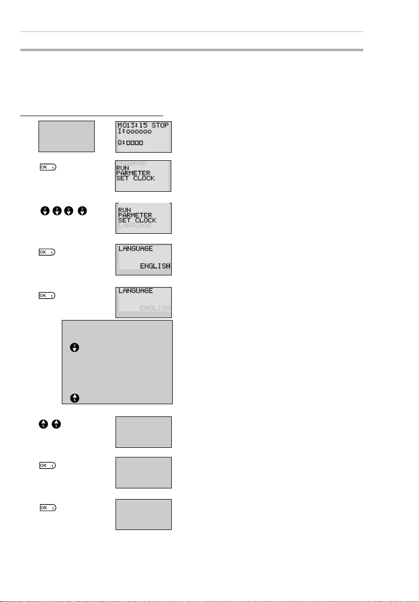
Selecting Display Language Section 3-1
3-1 Selecting Display Language
There is a choice of 6 display languages for LCD-type CPU Units. The
default language is English.
Operation to Select German
Tur n ON
the power.
Press the OK Button to change to the Menu
Screen.
▼
Press the Down Button 4 times to move the
cursor to “LANGUAGE”.
▲▼
Press the OK Button to display the current
language (“ENGLISH”). The final “H” will be
highlighted and flashing.
Press the OK Button to make the whole word
“ENGLISH” flash. A different language can
now be selected.
Use the Up/Down Buttons to
select a language.
SPANISH
ITALIAN
¯
FRENCH
GERMAN
JAPANESE
ENGLISH
50
LANGUAGE
LANGUAGE
SET?
OK /ESC
RUN
PARAMETER
KALENDER
SPRACHE
▲▼
GERMAN
GERMAN
Press the Up Button to select GERMAN.
Press the OK Button to display a confirmation message.
Press OK to set the new language.
The display language will change to German.
Press the OK Button to complete the setting.
Page 75

Setting the Date and Time Section 3-2
3-2 Setting the Date and Time
The date and time are not set when the product is shipped. The date and
time must be set for models with calendar and time functions before the
ZEN can be used.
Select SET
CLOCK.
PROGRAM
RUN
PARAMETER
SET CLOCK
▼
SET CLOCK
SUMMER TIME
Press the OK Button to display the submenu
for clock settings. Select SET CLOCK from
the submenu.
SET C
SE LOCK
yy
yy/mm /dd
00
00 /01/01
Current date: yy/mm/dd
Current time: hh:mm (day)
Days of the week
SU: Sunday
MO: Monday
TU: Tuesday
WE: Wednesday
TH: Thursday
FR: Friday
SA: Saturday
SET CLOCK
yy/mm/dd
00/04/ 01
11: 3
SET CLOCK
SET ?
OK /ESC
11:35(SU)
00:03(SA)
5 (SU )
Press the OK Button to display the current
date and time settings. The right digit of the
date will be highlighted and flashing.
Set the date and time.
Use the Up/Down Buttons to change the setting.
Use the Left/Right Buttons to move the cur-
sor.
The day will automatically change when the
date is set.
Press the OK Button to display a confirmation message.
Press the OK Button to confirm and complete the setting.
51
Page 76

Creating Ladder Programs Section 3-3
!Caution
If the power supply is turned OFF for an extended period of time
(2 days or more at 25°C), the date and time will return to the
default setting (00/1/1; 00:00 (SA)). This may cause programs
using calendar timers or weekly timers to malfunction. Therefore,
mount a Battery Unit for the system if the power supply is
expected to be interrupted for an extended time. (Refer to
page 96.)
Note 1. The year can be set between 2000 and
2099.
2. If Summertime is set, “S” will appear at
the top right of the time setting screen
during the Summertime period. (Refer to
page 93.)
SET CLO CK S
yy /mm/dd
01/05/01
00:00( TU)
3-3 Creating Ladder Programs
Example Program
This section explains how to write ladder pro-
SW1 SW2
Ry
Ry
grams for LCD-type CPU Units, based on a
simple circuit example.
Refer to the ZEN-SOFT01-V3 ZEN Support
Software Operation Manual (Z184) for information on programming LED-type CPU
Units.
“S” displayed during
Summertime period
52
Page 77

Creating Ladder Programs Section 3-3
3-3-1 I/O Wiring and Internal Operation
L
Power supply
terminals
Ladder
program
Output terminals
SW1 SW2
N
L N I0 I2 I3I1
(1) (2)
I0 I1
Q0
(3)
Q0 Q1
Load
Input terminals
Q0
Connect switches SW1 and SW2
to input terminals I0 and I1.
When SW1, connected to input bit
I0, turns ON or OFF, I0 (indicated
by (1) in the diagram) turns ON or
OFF.
When SW2, connected to input bit
I1, turns ON or OFF, I1 (indicated
by (2) in the diagram) turns ON or
OFF.
If the ladder program is executed
in RUN mode and SW1 turns ON,
input bit I0 turns ON, output bit Q0
turns ON, and the output contact
(indicated by (3) in the diagram)
turns ON.
When the output contact (3) turns
ON, the load connected to output
terminal Q0 turns ON.
3-3-2 Clearing Programs
Clear the ladder program before starting to
write a program. By performing the Delete
Program operation, the ladder program will
be completely cleared. The display language, date/time settings, and all other settings will not be initialized.
STOP mode
display
PROGRAM
RUN
PARAMETER
SET CLO CK
▼
EDIT PROG
DELETE PROG
DELET E PRO G
DELE TE?
OK/ ESC
Press the OK Button to switch to the Menu
Screen and select PROGRAM.
Select DELETE PROG.
If a password has been set, a Password
Input Screen will be displayed. Input the
password.
Press the OK Button to display a confirmation message.
53
Page 78

Creating Ladder Programs Section 3-3
EDIT PROG
DELE TE PROG
When the Delete Program operation has
been completed, the display will return to the
original screen.
3-3-3 Writing Ladder Programs
STOP mode
display
PROGRAM
RUN
PARAMETER
SET CLOCK
▼
EDIT PROG
DELE TE PROG
Press the OK Button to switch to the Menu
Screen and select PROGRAM.
Select EDIT PROGRAM.
Indicates the line number in the ladder program at the cursor position (line 0 in this
example.)
Cursor flashing in a reversed state.
Press the OK Button to switch to the Ladder
Program Edit Screen.
54
Page 79

Creating Ladder Programs Section 3-3
Operations in the Ladder Program Edit Screen
Two lines of circuits can be displayed at one
time on the Ladder Program Edit Screen.
• Up to 96 lines can be written.
• Up to 3 inputs and 1 output can be written per line.
• Example ladder diagram
Bit type
Bit address
Connection
line
▼
▼
N.C. input
N.O. input
Positions for Writing Inputs, Outputs, and Connection Lines
Additional output functions
Ladder program line number at cursor
Bit address
Bit type
Displayed when there are more lines. Use the Down Button to
display the lines.
Displayed when there are more lines. Use the Up Button to
display the lines.
Input write positions
Bit type/bit number
Input symbol (N.O./N.C) or connection line
Bit/timer/counter/
output write positions
Connection line write positions
55
Page 80

Creating Ladder Programs Section 3-3
3-3-3-1 Writing an Input for I0
Press the OK Button to display the initial
write setting (N.O input I0) and move the
▼
flashing cursor to the bit type I position. Use
the Up/Down Buttons to select the bit type.
Use the Right Button to move the flashing
cursor to the 0 position and then use the Up/
Down Buttons to select the bit address.
Press the OK Button twice to complete the
write operation for input I0. The highlighted
▼
cursor will move the next input position.
3-3-3-2 Writing Serial Input I1
Press the OK Button to display the N.O. input
and input I0 again.
▼
Press the ALT Button to switch to a N.C.
input.
▼
▼
(Press the ALT Button again to switch back
to a N.O. input.)
Use the Right Button to move the flashing
cursor to the bit address position and use the
Up Button to change the bit address to 1.
Writing Inputs
Input Symbol Configuration
56
Press the OK Button to move the highlighted
cursor to the next input position. A connec-
▼
tion will automatically be created between
input I0 and the next input.
Bit type
Bit number
Input symbols ( N.O. input;
N.C. input.)
Page 81

Creating Ladder Programs Section 3-3
Memory Areas
Symbol Name Bit type and number
I CPU Unit input bits I0 to I 5 (6 points) (See note 1.)
Q CPU Unit output bits Q0 to Q3 (4 points) (See note 2.)
X Expansion I/O Unit input
bits
Y Expansion I/O Unit output
bits
M Work bits M0 to Mf (16 points)
H Holding bits H0 to Hf (16 points)
B Button switches B0 to B7 (8 points) (See note 4.)
X0 to Xb (12 points) (See note 3.)
Y0 to Yb (12 points) (See note 3.)
Note
1. I0 to Ib (12 points) for CPU Units with 20
I/O points.
2. Q0 to Q7 (8 points) for CPU Units with 20
I/O points.
3. Can be used only when Expansion I/O
Units are connected.
4. Can be used only when LCD-type CPU
Units are used.
Timers, Counters, and Analog Comparators
Symbol Name Bit type and number
T Timers T0 to Tf (16 timers)
# Holding timers #0 to #7 (8 timers)
@ Weekly timers @0 to @f (16 timers) (See note
* Calendar timers *0 to *f (16 timers) (See note
C Counters C0 to Cf (16 counter)
A Analog comparators A0 to A3 (4 comparators)
P Comparators P0 to Pf (16 comparators)
Note
1. Can be used only with CPU Units with
calendar and clock functions.
2. Can be used only with CPU Units with
DC power supply.
Press the ALT Button to enable drawing a
connection line. The left arrow cursor will
▼
flash.
1.)
1.)
(See note 2.)
57
Page 82

Creating Ladder Programs Section 3-3
Press the Right Button to draw a connection
line to the output.
▼
Writing Outputs
Output Configuration
Bit number
Bit type
Additional functions
■
Memory Areas
Symbol Name Bit type and number
Q CPU Unit output bits Q0 to Q3 (4 outputs) (See note 1.)
Y Expansion I/O Unit output
bits
M Work bits M0 to Mf (16 bits)
H Holding bits H0 to Hf (16 bits)
Y0 to Yb (12 outputs) (See note 2.)
58
Note
1. Q0 to Q7 (8 points) for CPU Units with 20
I/O points.
2. Can be used only when Expansion I/O
Units are connected.
■
Additional Functions for Output Bits
Symbol Name
[ Normal operation
S Set operation
R Reset operation
A Alternate operation
Page 83

Creating Ladder Programs Section 3-3
Additional Functions for Bit Outputs
[: Normal output S: Set R: Reset A: Alternate
I0
Q0
Q0 turns ON and OFF
when execution condition I0 turns ON and
OFF.
I1
Q1
Q1 turns ON and stays
ON when execution
condition I1 turns ON
once.
I2
Q2
Q2 is forced OFF
when execution condition I2 turns ON.
I3
Q3
Q3 alternates between
On and OFF each time
execution condition I3
turns ON.
Timers, Holding Timers, Counters, and Display Output Configurations
Timer/counter/display number
Timer/counter/display type
Timer/counter output type
■
Timers, Counters, and Display Bits
Symbol Name Type and number Output type
T Timer T0 to Tf (16 timers) T: Trigger
# Holding timer #0 to #7 (8 timers)
C Counter C0 to Cf (16 counters) C: Count
D Display bit D0 to Df (16 bits)
Note
(See note 2.)
1. These memory areas are smaller for the
R: Reset
D: Count direction
R: Reset
D
pre-V1 CPU Units.
2. For LCD-type CPU Units only.
3-3-3-3 Writing an Output to Q0
▼
▼
Press the Right Button again to draw a line
to the output and move the highlighted cursor
to the output write position.
Press the OK Button to display the initial
value for the output (normal output/Q0) and
move the flashing cursor to the bit type Q
position.
Use the Up/Down Buttons to select the bit
type. Use the Right/Left Buttons to move the
flashing cursor and use the Up/Down But-
59
Page 84

Creating Ladder Programs Section 3-3
tons to select additional functions or select
the bit address.
Press the OK Button twice to complete writing output Q0. The highlighted cursor will
▼
move to the input at the beginning of the next
line.
3-3-3-4 Writing a Parallel Input for Q0
Press the OK Button to display input I0 and
move the flashing cursor to the bit type I
▼
position.
Press the Up Button to select Q (a CPU Unit
output bit).
▼
Press the OK Button twice to complete writing the parallel input for Q0. The highlighted
▼
cursor will move to the next input.
3-3-3-5 Drawing Connection Lines for OR Circuits
Drawing Connection Lines
Horizontal connection lines
Vertical connection lines
60
Intersecting lines
Press the ALT Button when the highlighted
cursor is at the input write position to change
the cursor to a left flashing arrow and enable
connection lines to be drawn. Move the left
arrow the position for drawing the connection
line and press the Up, Down, Left, and
Right Buttons to draw connection lines vertically and horizontally.
It will not be possible to draw connection
lines when the beginning or end of the line
has been reached or if the OK and ESC Buttons are pressed.
Press the ALT Button to enable drawing con-
nection lines.
▼
Page 85

Creating Ladder Programs Section 3-3
Press the Up Button to simultaneously draw
a connection line both vertically and horizon-
▼
▼
Note
1. Always press the ESC Button and return to the Menu Screen
after creating a program. If you do not press the ESC Button
and return to the Menu Screen before turning OFF the power,
the program and settings will be deleted.
2. Do not input a program where the connection lines double
back on themselves. The program will not operate properly if
such lines are drawn.
3. Do not use the same output bit address for more than one output from the program. The resulting operation may not be as
expected.
I0
I1
tally. The cross (+) indicates an intersection.
Press the OK Button to complete writing the
connection line and change to a highlighted
flashing cursor.
Press the ESC Button to complete the write
operation.
Press the ESC Button again to return to the
Menu Screen.
[Q0
Here, the final status of Q0
[Q0
will be controlled by I1, not
by I0.
61
Page 86

Confirming Ladder Program Operation Section 3-4
3-4 Confirming Ladder Program Operation
Always check the ladder program operation before using the ZEN.
Note 1. Before turning ON the power, check that the power supply, input
circuits, and output circuits have been wired correctly.
2. For systems with loads connected to the outputs that may cause
serious injury or damage to equipment if operation is incorrect, remove the output wiring before performing trial operation.
3. Always ensure safety in the vicinity before turning ON the power
or switching operating modes.
Procedure for Checking Operation
Checks Before Turning ON the Power
1. Check that the ZEN is mounted and wired correctly.
2. Check that the operation of the ZEN will not have a negative impact on the system. Check for any dangers.
3. Turn ON the power supply to the ZEN.
Switch to RUN mode while the ZEN is stopped.
Operation Checks
4. Turn each input ON and OFF and check that the program is operating correctly.
5. Adjust any problems.
Method for Checking Operation
LCD-type CPU
Units
LED-type CPU
Units
Check the operation by the flashing input and output displays on the Main
Screen.
Connect the ZEN Support Software and check operation using the monitor
function. Refer to the operation manual for the ZEN Support Software.
62
Page 87

Confirming Ladder Program Operation Section 3-4
Checking Operation
Changing Operating Mode
Turn I0 ON.
I0 I1
Turn I0 OFF.
I0 I1
PROGRAM
RUN
PARAMETER
SET CLOCK
▼
MONITOR
STOP
PARAMETER
SET CLOCK
RUN
▼
Checking Operations on
Main Screen
Press the ESC
Button to switch
to the Main
Screen.
Q0 will turn ON when
I0 turns ON.
I0 ON.
Q0 ON at the same
time.
Q0 remains ON
even if I0 turns OFF.
I0 OFF.
Q0 ON.
Press the OK Button to display the Menu
Screen and press the Down Button to move
the flashing cursor to RUN.
Press the OK Button to switch from STOP
mode to RUN mode.
Checking Operations Using
Ladder Program Monitor
MONITOR
STOP
PAR AME TE R
SET CLOCK
RUN
Select Monitor
in RUN mode.
▼
Press the OK
Button to switch
to the Ladder
Program
Monitoring
Screen.
Q0 turns ON at
the same time
when I0 turns
ON. When the
bit is ON, the
vertical and
horizontal lines
are thick.
Turn I1 ON.
I0 I1
Q0 will turn OFF when
I1 is turned ON.
I1 ON.
Q0 OFF.
63
Page 88

Correcting Ladder Programs Section 3-5
3-5 Correcting Ladder Programs
3-5-1 Changing Inputs
Change contact Q0 to M1.
Move the
highlighted cursor
to the input to be
changed.
Press the OK Button to change the high-
/
3-5-2 Changing Additional Bit Output Functions
Move the
highlighted cursor
to the output to be
changed.
lighted cursor to a flashing cursor and move
the flashing cursor to the bit type position.
Use the Up/Down Buttons to select M.
Press the Right Button to move the flashing
cursor to the bit address position. Use the
Up/Down Buttons to change the bit address
from 0 to 1.
Press the OK Button to complete the setting
change.
Change the additional function for the input
for Q0 to S (Set).
64
Press the OK Button to change the highlighted cursor to a flashing cursor.
Press the Left Button to move the flashing
cursor to the additional function position.
Press the Up Button twice to change the
additional function from [ to S.
Press the OK Button to complete the
change.
Page 89

Correcting Ladder Programs Section 3-5
3-5-3 Deleting Inputs, Outputs, and Connection Lines
Move the highlighted cursor to the position of
the input, output, or connection line to be
deleted and press the DEL Button.
Example: Deleting Serial Input M3
Move the highlighted cursor to the
position of the input
to be deleted.
Press the DEL Button to delete the input and
the related connecting lines at the same
time.
Example: Deleting Vertical Connecting Lines
Move the highlighted cursor to the input position to the right of the vertical line to be
deleted. Press the ALT Button to enable
drawing connection lines. The highlighted
cursor will change to a left arrow cursor.
Press the DEL Button to delete the vertical
connection line.
3-5-4 Inserting Lines
• To insert a blank line, move the highlighted cursor to the beginning of the line where
the blank line is to be inserted and press the ALT Button.
Move the highlighted
cursor to the beginning
of the next line (the line
that will be after the
inserted line.)
A circuit will be added here.
Press the ALT Button to insert one blank line.
Blank line
• To add OR programming, inputs can be added between parallel inputs. Move the
highlighted cursor to the beginning of the line where the input is to be inserted.
Move the highlighted
cursor to the beginning
of the next line (the line
that will be after the
inserted li ne.)
A input will be added here.
65
Page 90

Correcting Ladder Programs Section 3-5
Press the ALT Button to reserve a 1-line
Blank line
space between the parallel inputs.
The vertical connection lines will be automatically extended.
Note A blank line cannot be inserted if an input or connection line is
written in the last line (the 96th line).
3-5-5 Deleting Blank Lines
To delete a blank line, move the highlighted
cursor to the input position at the beginning
of the line to be deleted and press the DEL
Button.
Move the highlighted cursor to the
beginning of the
line to be deleted.
Note A line must be blank to be deleted, i.e., lines containing inputs
▼
and outputs cannot be deleted.
This line will be deleted.
Press the DEL Button to delete one blank
line. All following lines will move up one.
66
Page 91

Using Timers (T) and Holding Timers (#) Section 3-6
3-6 Using Timers (T) and Holding Timers (#)
The ZEN has 16 built-in timers and 8 built-in holding timers.
Timers The present value being timed will be reset when the timer switches from RUN
Holding timers The present value being timed is held even when the timer switches from RUN
Timer Operation (T0 to Tf)
Timer type Operation Main
X ON delay
timer
mode to STOP mode or the power is turned OFF.
There are four uses of the timer available, depending on the additional function
selection.
mode to STOP mode or the power is turned OFF. The time will continue when
the trigger input turns ON again. The ON status of the timer bit is also held
when the timer times out.
Only ON-delay holding timers are supported.
applications
Tu r ns ON
after a set
interval after
the trigger
input has
turned ON.
Trigger input
Reset input
Setting
Present
value
0
Timer bit
Time lag operations
OFF delay
■
timer
O One-shot
pulse timer
F Flashing pulse
timer
Note Only T0 to T7 (8 points) are supported by pre-V1 CPU Units.
Stays ON
while the trigger input is
ON and turns
OFF after a
set interval
after the trigger input has
turned OFF.
Remains ON
for a set interval when the
trigger input
turns ON.
Turns ON and
OFF repeatedly at set
intervals while
the trigger
input is ON.
Trigger input
Reset input
Setting
Present
value
0
Timer bit
Trigger input
Reset input
Setting
Present
value
0
Timer bit
Trigger input
Reset input
Setting
Present
value
0
Timer bit
Useful for timing for lighting
and ventilating fans
Useful for
quantitative
operation
where operation is always
required for
the same
period.
Useful as an
alarm circuit
for flashing
emergency
lighting or
buzzers.
67
Page 92

Using Timers (T) and Holding Timers (#) Section 3-6
Holding Timer Operation (#0 to #7)
Timer type Operation Main
X ON delay
timer only
Tu r ns ON
after a set
interval after
the trigger
input has
turned ON.
Trigger input
Reset input
Setting
Present
value
Timer bit
0
Note Only #0 to #3 (4 points) are supported by pre-V1 CPU Units.
applications
When operation is to be
continued
even during
momentary
power interruptions and
longer power
interruptions.
3-6-1 Settings in the Ladder Program Edit Screen
Timer triggers, reset outputs, and timer inputs are drawn on the Ladder
Program Edit Screen. Settings are made on the Parameter Settings
Screen.
Trigger specification
Timer number
Trigger input
Reset input
Timer address
Timer bit
Timer trigger output
Timer reset output
Reset specification
Time up output
Timer address Timers: T0 to Tf (16 timers)/ Holding Timers: #0 to #7 (8 timers)
Trigger input T (TRG) Controls the timer trigger output. Triggers the timer when the trigger
Reset input R (RES) Controls the timer reset output. When the reset input turns ON, the
Timer bit Turns ON according to the timer type.
input turns ON.
present value is reset to 0 and the timer bit turns OFF. Trigger inputs
are not accepted while the reset input is ON.
Note Only T0 to T7 (8 points) and #0 to #3 (4 points) are supported by
pre-V1 CPU Units.
3-6-2 Settings in the Parameter Settings Screen
Timer type Time units (s)
Timer address
68
Monitor enabled/disabled
Set value
Page 93

Using Timers (T) and Holding Timers (#) Section 3-6
Timer Types
X ON delay
■
OFF delay
O One-shot pulse
F Flashing pulse
Time Units and Settings
S 00.01 to 99.99 s (in 0.01-s units) Error: 0 to –10 ms
M:S 00 min 01 s to 99 min 59 s (in minutes and sec-
onds)
H:M 00 h 01 m to 99 h 59 m (in hours and minutes) Error: 0 to –1 min
Error: 0 to –1 s
Monitor Enabled or Disabled
A Operating parameters can be monitored and settings changed.
D Operating parameters cannot be monitored nor settings changed.
3-6-3 Parameter Monitor Screen Display
Trigger input status
( : OFF/ : ON)
❍●
Reset input status
( : OFF/ : ON)
❍●
RUN
Timer present value
Timer bit status
( : OFF/ : ON)
❍●
Timer setting
69
Page 94

Using Counters (C) Section 3-7
3-7 Using Counters (C)
Up to 16 counters can be used in incremental or decremental mode. The
present value for counters and the status of counter bits (ON/OFF) are
held even when the operating mode is changed or there is a power interruption.
Operation
Counter bits turn ON when the count value (present value) exceeds the
setting (present value ³ set value). The count returns to 0 and the bits
turns OFF when the reset input turns ON. Count inputs are not accepted
while the reset input is ON.
I0 (DIR)
I1 (CNT)
I2 (RES)
Set value
Present value
0000
Counter bit
3-7-1 Settings in the Ladder Program Edit Screen
Outputs for the counter input, counter direction, and counter reset are
written in the Ladder Program Edit Screen. Counter input conditions can
also be written. Settings are made in the Parameter Settings Screen.
Count input specification
Counter address
Count input
Counter direction
specification input
Reset input
Counter address
Counter bit
Output to counter input
Counter direction specification output
Counter direction specification
Counter reset output
Reset specification
Counter bit output
70
Counter address C0 to Cf (16 points)
Counter input C (CNT) Increments (or decrements) each time the
Counter direction specification input
D (DIR) Switches between incremental and decremen-
count input turns ON.
tal counting.
OFF: Incremental
ON: Decremental
Page 95

Using Counters (C) Section 3-7
Reset input R (RES) When the reset input turns ON, the present
Count input Turns ON when the counter has counted out (PV ³ SV)
Note
Only C0 to C7 (8 points) are supported by pre-V1 CPU Units.
value returns to 0 and the counter bit turns
OFF. Count inputs are not accepted while the
reset input is ON.
3-7-2 Settings in the Parameter Settings Screen
Counter address
Set value 0001 to 9999 (4 decimal digits) times
Monitor enabled/
disabled
A Operating parameters can be monitored and
D Operating parameters cannot be monitored or
Monitor enabled/disabled
Set value
settings changed.
settings changed.
3-7-3 Parameter Monitor Screen Display
Count input status
( : OFF/ : ON)
❍●
Counter direction specification
input status ( : OFF/ : ON)
❍●
Counter present value
RUN
Reset input status
( : OFF/ : ON)
❍
Counter bit status ( : OFF/ : ON)
Counter setting
●
❍●
Note 1. To reset the counter present value and counter bit status (ON/
OFF) when at power interruptions or when the operating mode is
changed, create a counter reset circuit when you first execute the
program. An example is shown below.
Counter reset
output
2. If the counter input and counter direction are input simultaneously, place the output for the counter direction before the output for
the counter input in the program.
Counter direction specification output
Output to counter input
71
Page 96

Using Weekly Timers (@) Section 3-8
3-8 Using Weekly Timers (@)
Weekly timers turn ON between the specified start and stop times on
the specified days. Weekly timers have 16 points (@0 to @f.)
Operation
Day of the week
Mon Tues Wed Thurs Fri Sat Sun
24:00
Stop time
Start time
Time
17:30
8:15
0:00
Weekly t imer
bit
In this example, the weekly timer turns ON every day
from Tuesday to Friday between 8:15 and 17:30.
3-8-1 Settings in the Ladder Program Edit Screen
Weekly timer inputs are written in the Ladder Program Edit Screen.
Settings are made in the Parameter Settings Screen.
Weekly timer address
Time up output
Weekly timer addresses @0 to @f (16 timers)
Note Only @0 to @7 (8 points) are supported by pre-V1 CPU Units.
3-8-2 Settings in the Parameter Settings Screen
Weekly timer address
Start day
Stop day
Monitor enabled/disabled
Start time
Stop time
72
Note When the flashing cursor is on the start day, press the Right But-
ton and then the Up/Down Buttons to set the stop day. If the stop
day is not set, the timer will operate according to the set time only.
Day Start day Sun/Mon/Tues/Wed/Thurs/Fri/Sat
Stop day Sun/Mon/Tues/Wed/Thurs/Fri/Sat/None
Page 97

Using Weekly Timers (@) Section 3-8
Time Start time 00:00 to 23:59
Stop time 00:00 to 23:59
Monitor
enabled/disabled
Relationship between Start and Stop Days and Times
Setting and operation Setting
Start and stop
day
Start and stop
time
When start day
is before stop
day
When start day
is after stop day
When start and
stop days are
the same
When stop day
not set
When start time
is before stop
time
When start time
is after stop time
When start and
stop times are
the same
A Operating parameters can be monitored
D Operating parameters cannot be moni-
example
MO - FR Operates Monday to Friday every week.
FR - MO Operates every Friday through to the following
SU - SU Operates regardless of the day of the week.
SU - Operates every Sunday only.
ON: 08:00
OFF: 17:00
ON: 21:00
OFF: 06:00
ON: 13:00
OFF: 13:00
and settings changed.
tored or settings changed.
Operation
Monday.
Operates 8:00 to 17:00 every day.
Operates 21:00 to 6:00 the next day.
Operates regardless of the time.
3-8-3 Parameter Monitor Screen Display
Start day
Stop time
Stop day
Current time
Weekly timer bit status
( : OFF/ : ON)
❍●
Start time
Current day
RUN
73
Page 98

Using Calendar Timers (*) Section 3-9
3-9 Using Calendar Timers (*)
Calendar timers turn ON between specified dates. There are 16 calendar timers (*0 to *f).
Operation
Dec 31
End date Sep 1
Start date
3-9-1 Settings in the Ladder Program Edit Screen
Apr 1
Jan 1
Calendar timer
bit
The calendar timer bit is ON between 1
April and 31 August.
Calendar timer inputs are written in the Ladder Program Edit Screen.
Settings are made in the Parameter Settings Screen.
Calendar timer address
Time up output
Calendar timer address *0 to *f (16 timers)
Note Only *0 to *7 (8 points) are supported by pre-V1 CPU Units.
3-9-2 Settings in the Parameter Settings Screen
Calendar timer address
Monitor enabled/disabled
Start date
Stop date
Start date Jan 1 to Dec 31
Stop date (See note.) Jan 1 to Dec 31
Monitor enabled/
disabled
74
A Operating parameters can be monitored and
settings changed.
D Operating parameters cannot be monitored or
settings changed.
Page 99

Analog Inputs (Analog Comparators (A)) Section 3-10
Relationship between Start and Stop Dates
Setting and operation Setting
Start and stop
date settings
and operation
When start date is
before stop date
When start date is
after stop date
When start and
stop dates are the
same.
example
ON: 04/01
OFF: 09/01
ON: 12/26
OFF: 01/07
ON: 07/26
OFF: 07/26
Operates between 1 April and 31 August.
(See note.)
Operates between 26 December and 6
January the following year.
Operates regardless of the date.
Operation
Note To stop operation on August 31, set the stop date to the following
day (September 1).
3-9-3 Parameter Monitor Screen Display
Current date
Calendar timer bit status ( : OFF/ : ON)
RUN
Start date
Stop date
❍●
3-10 Analog Inputs (Analog Comparators (A))
Two analog voltage inputs between 0 and 10 V can be incorporated
into the CPU Units with a DC power supply. I4 and I5 for CPU Units
with 10 I/O points and Ia and Ib for CPU Units with 20 I/O points can
be used as analog voltage inputs.
The analog input signal is converted to BCD (00.0 to 10.0). The
results can be used with one of the comparators A0 to A3, and the 4
comparison outputs can be used as input conditions in the program.
75
Page 100

Analog Inputs (Analog Comparators (A)) Section 3-10
+ −
Device with
analog voltage
output
COM
24 VDC
(DC power supply type)
Analog input 1: I4
Analog input 2: I5
Note
Connect the negative side to COM for V1 CPU Units. The analog
input circuit may be destroyed if the positive side is connected to
COM.
Operation
•Example 1
(When comparison shows analog
input 1 ³ 5.2 V)
Setting
10.5
10.0
Analog signal input:
0.0 to 10.0 V
24 VDC
+ −
20C1DR-D-V110C1DR-D-V1
Analog input: Ia
Analog input: Ib
Converted value
Device with
analog voltage
output
COM
I0I1I2I3I4I
5
Q
4
I6I7I8I9IaI
Q6Q
5
Q
7
DC power supply type
•Example 2
(When comparison shows analog
input 1 is £ analog input 2)
10.0
Analog input 1
b
5.2
00.0
Analog
comparator
bit
0.0
The analog comparator bit turns
ON when the analog input voltage
reaches is 5.2 V or higher.
Note Do not make negative signal inputs to analog inputs. If negative
76
Analog input 2
10.0 V
10.5 V
Input voltage
00.0
Analog
comparator
bit
The analog comparator bit turns ON
when the analog input 2 voltage is
higher than the analog input 1 voltage.
signals are made, the internal elements may be damaged.
 Loading...