

Manual No.
TOE-S606-12F-OY
VS mini J7
Compact General Purpose Inverter
USER’S MANUAL

PREFACE
2
YASKAWA’s VS mini J7 (hereinafter, called VS mini).
is a small and simple inverter; as easy as using a
contactor. This instruction manual describes
installation, maintenance and inspection,
troubleshooting, and specifications of the VS mini.
Read this instruction manual thoroughly before
operation.
OMRON YASKAWA Motion Control B.V.
General Precautions
• Some drawings in this manual are shown with the protective cover or
shields removed, in order to describe detail with more clarity. Make
sure all covers and shields are replaced before operating this product.
• This manual may be modified when necessary because of improvement
of the product, modification, or changes in specifications.
Such modifications are denoted by a revised manual No.
• To order a copy of this manual, if your copy has been damaged or lost,
contact your OYMC representative.
• OYMC is not responsible for any modification of the product made by
the user, since that will void your guarantee.
NOTES FOR SAFE OPERATION
Read this instruction manual thoroughly before installation, operation,
maintenance or inspection of the VS mini. In this manual, NOTES FOR
SAFE OPERATION are classified as “WARNING” or “CAUTION.”
Indicates a potentially hazardous situation which, if not avoided, could result
in death or serious injury to personnel.
Indicates a potentially hazardous situation which, if not avoided, may result
in minor or moderate injury to personnel and damage to equipment.
It may also be used to alert against unsafe practices.
Even items described in may result in a vital accident in some
situations. In either case, follow these important notes.
: These are steps to be taken to insure proper operation.
NOTE
CAUTION
3
WARNING
CAUTION
4
WARNINGS FOR UL/cUL MARKING
• Do not connect or disconnect wiring, or perform signal checks while the
power supply is turned ON.
• The Inverter internal capacitor is still charged even after the power supply
is turnd OFF. To prevent electric shock, disconnect all power before
servicing the Inverter. Then wait at least one minute after the power
supply is disconnected and all indecators are OFF.
• Do not perform a withstand voltage test on any part of the Inverter. This
electronic equipment uses semiconductors and is vulnerable to high
voltage.
• Do not remove the Digital Operator or the blank cover unless the power
supply is turned OFF. Never touch the printed control board (PCB) while
the power supply is turned ON.
• This Inverter is not suitable for use on a circuit capable of delivering more
than 18,000 RMS symmetrical amperes, 250volts maximum (200V class
units) or 18,000 RMS symmetrical amperes, 480volts maximum (400V
class units).
WARNINGS FOR CE MARKINGS
• Only basic insulation to meet the requirements of protection class 1 and
overvoltage category II is provided with control circuit terminals.
Additional insulation may be necessary in the end product to conform to
CE requirements.
• For 400 V class Inverters, make sure to ground the supply neutral to
conform to CE requirements.
• For conformance to EMC directives, refer to the relevant manuals for the
requirements.
Document No. EZZ008389 for Japanese version,
Document No. EZZ008390 for English version
CAUTION
Use 75°C copper wires or equivalent.
Low voltage wires shall be wired with Class I Wiring.
5
RECEIVING
CAUTION
(Ref. page)
• Do not install or operate any inverter which is damaged or
has missing parts.
Failure to observe this caution may result in personal injury or
equipment damage.
ччччччччччччччччччччччччччччччччччччччч15
MOUNTING
CAUTION
(Ref. page)
• Lift the cabinet by the heatsink. When moving the
unit, never lift by the plastic case or the terminal covers.
Otherwise, the main unit may be dropped causing damage
to the unit.
чччччччччччччччччччччччччччччччччччччччччччччч17
• Mount the inverter on nonflammable material (i.e. metal).
Failure to observe this caution can result in a fire.
ччччччччччччччч17
• When mounting units in an enclosure, install a fan or
other cooling device (open chasis to keep the intake air
temperature below 50: (122<).
Overheating may cause a fire or damage to the unit.
ччччччччччччч18
• The VS mini generates heat. For effective cooling,
mount it vertically.
Refer to the figure in “Mounting Dimensions” on page 18.

WIRING
6
WARNING
(Ref. page)
• Only commence wiring after verifying that the power
supply is turned OFF.
Failure to observe this warning can result in an electric shock
or a fire.
ччччччччччччччччччччччччччччччччччччччччччччччччч20
• Wiring should be performed only by qualified personnel.
Failure to observe this warning can result in an electric shock
or a fire.
ччччччччччччччччччччччччччччччччччччччччччччччччч20
• When wiring the emergency stop circuit, check the wiring
thoroughly before operation.
Failure to observe this warning can result in personal injury.
чччччч20
• For 400V class, make sure to ground the supply neutral.
Failure to observe this warning can result in an electric shock
or a fire. чччччччччччччччччччччччччччччччччччччччччччччччч24
• Make sure to ground the ground terminal according to the
local grounding code.
Failure to observe this warning can result in an electric shock
or a fire. чччччччччччччччччччччччччччччччччччччччччччччччч24

7
CAUTION
(Ref. page)
• Verify that the inverter rated voltage coincides with the
AC power supply voltage.
Failure to observe this caution can result in personal injury
or a fire.
• Do not perform a withstand voltage test of the inverter.
It may cause semi-conductor elements to be damaged.
• Make sure to tighten terminal screws of the main circuit
and the control circuit.
Failure to observe this caution can result in a malfunction,
damage or
a fire.
ччччччччччччччччччччччччччччччччччччччччч20
• Never connect the AC main circuit power supply to
output terminals U/T1, V/T2, and W/T3.
The inverter will be damaged and invalidate the guarantee.
чччччччч20
• Do not connect or disconnect wires or connectors
while power is applied to the circuit.
Failure to observe this caution can result in personal injury.
• Do not change signals during operation.
The machine or the inverter may be damaged.

OPERATION
8
WARNING
(Ref. page)
• Only turn ON the input power supply after replacing
the front cover.
Do not remove the covers while current is flowing.
Failure to observe this warning can result in an electric shock.
• Never operate the digital operator or dip the switches
when your hand is wet.
Failure to observe this warning can result in an electric shock.
• Never touch the terminals while current is flowing, even
during inverter stopping.
Failure to observe this warning can result in an electric shock.
• When the fault retry function is selected, stand clear of
the inverter or the load, since it may restart suddenly
after being stopped.
(Construct machine system, so as to assure safety for personnel,
even if the inverter should restart.)
Failure to observe this
warning can result in personal injury.
ччччччччччччччччччччччччч53
• When continuous operation after power recovery is
selected, stand clear of the inverter or the load, since
it may restart suddenly after being stopped.
(Construct machine system, so as to assure safety for personnel,
even if the inverter should restart.)
Failure to observe this
warning can result in personal injury.
ччччччччччччччччччччччччч48
• Since the digital operator stop button can be disabled
by a function setting, install a separate emergency
stop switch.
Failure to observe this warning can result in personal injury.
• If an alarm is reset with the operation signal ON, the inverter
restarts automatically. Only reset the alarm after verifying
that the operation signal is OFF.
Failure to observe this warning can result in personal injury.
ччччччч26
9
MAINTENANCE AND INSPECTION
CAUTION
(Ref. page)
• Never touch the heatsink since the temperature is very high.
Failure to observe this caution can result in harmful burns
to the body.
• Since it is easy to change operation speed from low to
high speed, verify the safe working range of the motor
and machine before operation.
Failure to observe this caution can result in personal injury
and machine damage.
• Install a holding brake separately if necessary.
Failure to observe this caution can result in personal injury.
• If using an Inverter with an elevator, take safety measures on the
elevator to prevent the elevator from dropping.
Failure to observe this caution can result in personal injury.
• Do not change signals during operation.
The machine or the inverter may be damaged.
• All the constants of the inverter have been preset
at the factory. Do not change the settings unnecessarily.
The inverter may be damaged.
чччччччччччччччччччччччччччччч27
WARNING
• Never touch high-voltage terminals in the inverter.
Failure to observe this warning can result in an electric shock.
•
Disconnect all power before performing maintenance or inspection.
Then wait at least one minute after the power supply is disconnected
and all LEDs and CHARGE LED are extinguished.
The capacitors are still charged and can be dangerous.
10
WARNING
• Never modify the product.
Failure to observe this warning can result in an electric shock or personal
injury and will invalidate the guarantee.
WARNING
(Ref. page)
• Do not perform withstand voltage test on any part
of the VS mini.
This electronic equipment uses semiconductors and is
vulnerable to high voltage.
• Only authorized personnel should be permitted to perform
maintenance, inspections or parts replacement.
[Remove all metal objects (watches, bracelets, etc.)
before operation.]
(Use tools which are insulated against electric shock.)
Failure to observe this warning can result in an electric shock.
чччччч84
CAUTION
(Ref. page)
• The control PC board employs CMOS ICs.
Do not touch the CMOS elements.
They are easily damaged by static electricity.
• Do not connect or disconnect wires, cooling fan or connentors
while power is applied to the circuit.
Failure to observe this caution can result in personal injury.
чччччччч84
Others
11
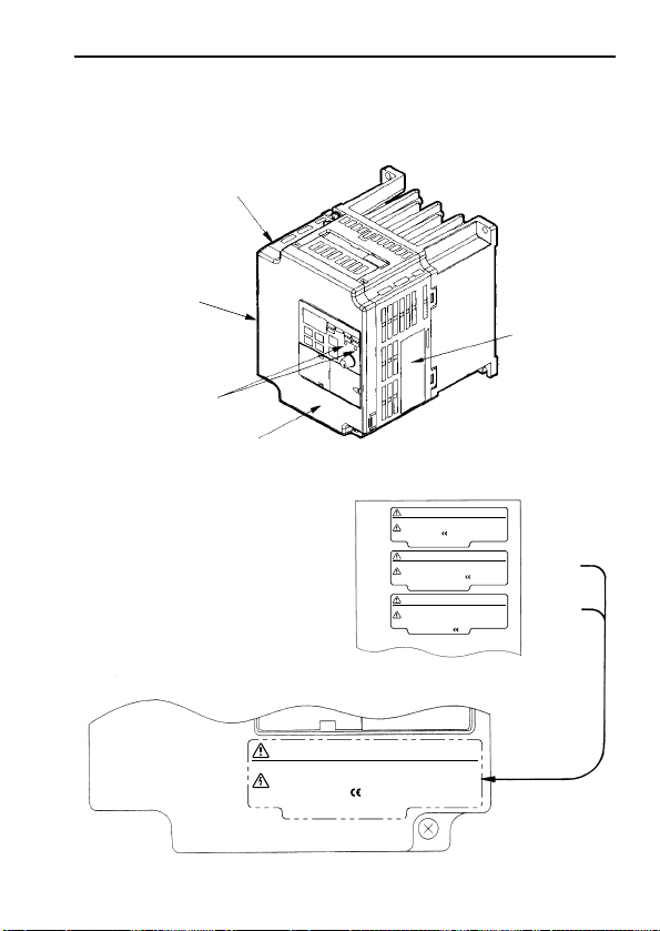
WARNING DISPLAY
A warning label is displayed on the front cover of the inverter, as shown
below. Follow these instructions when handling the inverter.
Example of 200V class, 3-phase, 1.5 kW inverter
Warning Display (Back of this manual)
Warning Display
〈English〉
〈French〉
〈Japanese〉
WARNING
– Risk of electric shock.
Read manual before installing.
Wait 1 minute for capacitor discharge after
disconnecting power supply.
To conform to requirements, make sure
to ground the supply neutral for 400V class.
•
•
•
危 険
−
けが・感電のおそれがあります。
据え付け、運転の前には必ず取扱説明書をお読み下さい。
通電中及び電源遮断後1分以内はフロントカバーを
外さないで下さい。
400V級インバータの場合は、電源の中性点が接地されて
いることを確認して下さい。( 対応)
•
•
•
WARNING
– Risk of electric shock.
Read manual before installing.
Wait 1 minute for capacitor discharge after
disconnecting power supply.
To conform to requirements, make sure
to ground the supply neutral for 400V class.
•
•
•
AVERTISSEMENT
–
Risque de décharge
électrique.
Lire le manuel avant I’installation.
Attendre 1 minute après la coupure de I’alimentation,
pour permettre la décharge des condensateurs.
Pour répondre aux exigences , s’assurer que le
neutre soit reli
é à la terre, pour la série
400V.
•
•
•
Japanese/French Warning Display
An English warning display is on
the front panel of the inverter.
If you need Japanese or French
warning display, a sheet of labels is
included. Place it over the English
warning display.
NAMEPLATE
PLASTIC CASE
QUALIFICATION
MARK
STATUS
INDICATOR
LAMP
WARNING
DISPLAY

CONTENTS
NOTES FOR SAFE OPERATION••••••••••••••••••••••••••••••3
1. RECEIVING•••••••••••••••••••••••••••••••••••••••••••••••••••••••••••••15
Checking the Name Plate ••••••••••••••••••••••••••••••••••••••••••••••15
2. IDENTIFYING THE PARTS••••••••••••••••••••••••••••••••••16
3. MOUNTING•••••••••••••••••••••••••••••••••••••••••••••••••••••••••••••17
Choosing a Location to Mount the Inverter•••••••••••••••••••••••••17
Mounting Dimensions••••••••••••••••••••••••••••••••••••••••••••••••••••18
Mounting/Removing Components ••••••••••••••••••••••••••••••••••••19
4. WIRING••••••••••••••••••••••••••••••••••••••••••••••••••••••••••••••••••••20
Wiring Instructions••••••••••••••••••••••••••••••••••••••••••••••••••••••••20
Wire and Terminal Screw Sizes•••••••••••••••••••••••••••••••••••••••21
Wiring the Main Circuit ••••••••••••••••••••••••••••••••••••••••••••••••••24
Wiring the Control Circuit •••••••••••••••••••••••••••••••••••••••••••••••25
Wiring Inspection••••••••••••••••••••••••••••••••••••••••••••••••••••••••••26
5. OPERATING THE INVERTER ••••••••••••••••••••••••••••27
Test Run ••••••••••••••••••••••••••••••••••••••••••••••••••••••••••••••••••••27
Operating the Digital Operator ••••••••••••••••••••••••••••••••••••••••29
LED Description•••••••••••••••••••••••••••••••••••••••••••••••••••••••••••31
Simple Data Setting ••••••••••••••••••••••••••••••••••••••••••••••••••••••35
6. PROGRAMMING FEATURES•••••••••••••••••••••••••••••36
Constant Set-up and Initialization ••••••••••••••••••••••••••••••••••••36
Selecting V/f pattern •••••••••••••••••••••••••••••••••••••••••••••••••••••37
Switching LOCAL/REMOTE Modes••••••••••••••••••••••••••••••••••40
Selecting Run/Stop Commands••••••••••••••••••••••••••••••••••••••••41
Selecting Frequency Reference•••••••••••••••••••••••••••••••••••••••42
Setting Operation Conditions ••••••••••••••••••••••••••••••••••••••••••43
Reverse run prohibit •••••••••••••••••••••••••••••••••••••••••••••••••••••43
Multi-step speed selection••••••••••••••••••••••••••••••••••••••••••••••43
Operating at low speed••••••••••••••••••••••••••••••••••••••••••••••••••44
Adjusting speed setting signal•••••••••••••••••••••••••••••••••••••••••45
Adjusting frequency upper and lower limits ••••••••••••••••••••••••47
Using two accel/decel times •••••••••••••••••••••••••••••••••••••••••••47
12

Automatic restart after momentary power loss ••••••••••••••••••••48
Soft-start characteristics ••••••••••••••••••••••••••••••••••••••••••••••••49
Torque detection ••••••••••••••••••••••••••••••••••••••••••••••••••••••••••50
Frequency detection •••••••••••••••••••••••••••••••••••••••••••••••••••••52
Jump frequencies•••••••••••••••••••••••••••••••••••••••••••••••••••••••••53
Continuing operation by automatic fault reset •••••••••••••••••••••53
Operating coasting motor without trip •••••••••••••••••••••••••••••••54
Holding accel/decel temporarily•••••••••••••••••••••••••••••••••••••••55
Using frequency meter or ammeter ••••••••••••••••••••••••••••••••••56
Calibrating frequency meter or ammeter •••••••••••••••••••••••••••56
Reducing motor noise or leakage current ••••••••••••••••••••••••••57
Operator stop key selection ••••••••••••••••••••••••••••••••••••••••••••59
Selecting Stopping Method•••••••••••••••••••••••••••••••••••••••••••••60
Selecting stopping method •••••••••••••••••••••••••••••••••••••••••••••60
Applying DC injection braking •••••••••••••••••••••••••••••••••••••••••61
Building Interface Circuits with External Devices •••••••••••••••••62
Using input signals •••••••••••••••••••••••••••••••••••••••••••••••••••••••62
Using output signals •••••••••••••••••••••••••••••••••••••••••••••••••••••65
Setting Frequency by Current Reference Input •••••••••••••••••••67
Preventing motor from stalling (Current limit)••••••••••••••••••••••69
Decreasing Motor Speed Fluctuation••••••••••••••••••••••••••••••••71
Slip compensation ••••••••••••••••••••••••••••••••••••••••••••••••••••••••71
Motor Protection ••••••••••••••••••••••••••••••••••••••••••••••••••••••••••72
Motor overload detection •••••••••••••••••••••••••••••••••••••••••••••••72
Selecting Cooling Fan Operation ••••••••••••••••••••••••••••••••••••73
Using MEMOBUS (MODBUS) Communications (Optional)
••••••••74
MEMOBUS (MODBUS) communications ••••••••••••••••••••••••••74
Communication specifications•••••••••••••••••••••••••••••••••••••••••74
Using Constant Copy Function••••••••••••••••••••••••••••••••••••••••75
Constant Copy function •••••••••••••••••••••••••••••••••••••••••••••••••75
READ function•••••••••••••••••••••••••••••••••••••••••••••••••••••••••••••77
COPY function•••••••••••••••••••••••••••••••••••••••••••••••••••••••••••••78
VERIFY function ••••••••••••••••••••••••••••••••••••••••••••••••••••••••••80
Inverter capacity display ••••••••••••••••••••••••••••••••••••••••••••••••81
Software No. display •••••••••••••••••••••••••••••••••••••••••••••••••••••82
13

14
7. MAINTENANCE AND INSPECTION ••••••••••••••••••84
Periodical Inspection ••••••••••••••••••••••••••••••••••••••••••••••••••••84
Part Replacement ••••••••••••••••••••••••••••••••••••••••••••••••••••••••84
8. FAULT DIAGNOSIS •••••••••••••••••••••••••••••••••••••••••••••87
Protective and Diagnostic Function ••••••••••••••••••••••••••••••••••87
Troubleshooting •••••••••••••••••••••••••••••••••••••••••••••••••••••••••••95
9. SPECIFICATIONS •••••••••••••••••••••••••••••••••••••••••••••••••98
Standard Specifications (200V Class)•••••••••••••••••••••••••••••••98
Standard Specifications (400V Class) •••••••••••••••••••••••••••••101
Standard Wiring •••••••••••••••••••••••••••••••••••••••••••••••••••••••••104
Sequence Input Connection with NPN/PNP Transistor •••••••106
Dimensions/Heat Loss•••••••••••••••••••••••••••••••••••••••••••••••••109
Recommended Peripheral Devices ••••••••••••••••••••••••••••••••111
Constants List••••••••••••••••••••••••••••••••••••••••••••••••••••••••••••113
1. RECEIVING
After unpacking the VS mini, check the following :
▫ Verify that the part numbers match your purchase order or packing slip.
▫ Check the unit for physical damage that may have occurred during
shipping.
If any part of VS mini is missing or damaged, call for service immediately.
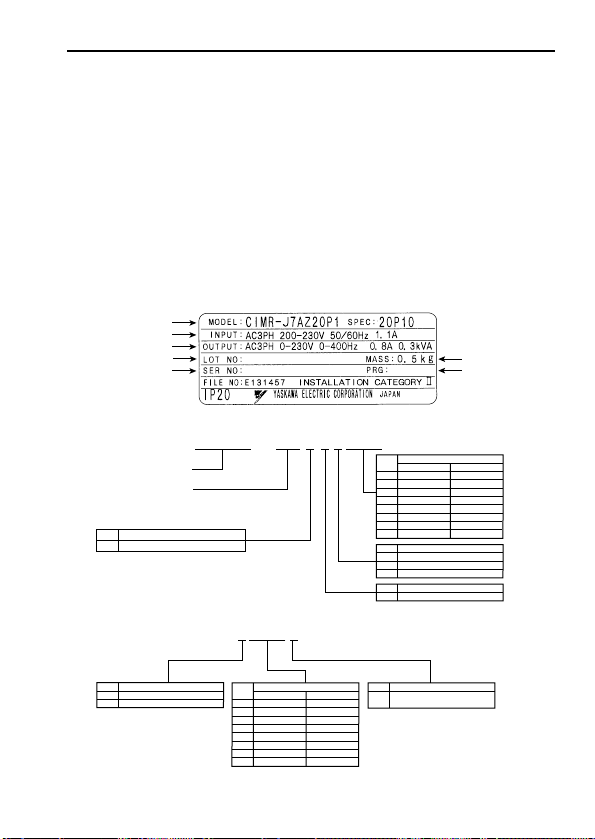
Checking the Name Plate
15
C I M R — J 7 A Z 2 0 P 1
Inverter
VS mini J7 Series
MODEL
No. AType
Digital operator provided (with potentiometer)
0P1
0P2
0P4
0P7
1P5
2P2
3P0
4P0
Applicable maximum motor output
No.
No.
B
2
4
Voltage Class
Single-phase 200VAC
Three-phase 200VAC
Three-phase 400VAC
No.ZSpecifications
OYMC standards
2 0 P 1 0
SPEC
B
2
4
Single-phase 200VAC
Three-phase 200VAC
Three-phase 400VAC
No. Protective structure
Open chassis
(IP20)
0
INVERTER MODEL
MASS
INPUT SPEC.
OUTPUT SPEC.
LOT NO.
SERIAL NO.
SOFTWARE NO.
0.1kW
0.25kW
0.55kW
1.1kW
1.5kW
2.2kW
–
4.0kW
200V class
–
0.37kW
0.55kW
1.1kW
1.5kW
2.2kW
3.0kW
4.0kW
400V class
0P1
0P2
0P4
0P7
1P5
2P2
3P0
4P0
Applicable maximum motor output
No.
0.1kW
0.25kW
0.55kW
1.1kW
1.5kW
2.2kW
–
4.0kW
200V class
–
0.37kW
0.55kW
1.1kW
1.5kW
2.2kW
3.0kW
4.0kW
400V class
Example of 3-phase, 200VAC, 0.1kW (0.13HP)
16
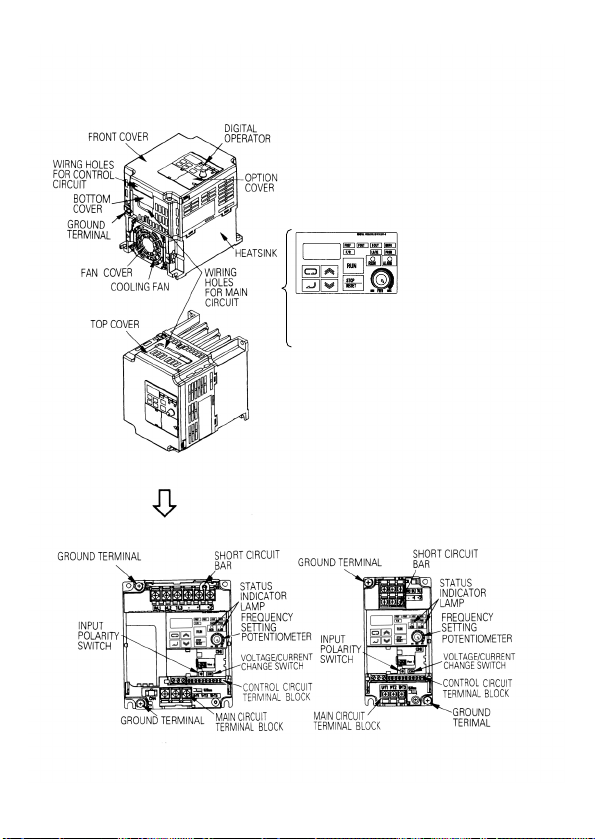
2. IDENTIFYING THE PARTS
CIMR-J7**21P5, 22P2, 24P0
B0P7, B1P5
40P2, 40P4, 40P7, 41P5
42P2, 43P0, 44P0
CIMR-J7
**
20P1, 20P2, 20P4, 20P7,
B0P1, B0P2, B0P4
Opening the covers
Digital operator (with potentiometer)
Used for setting or changing constants.
Frequency can be set using potentiometer.

17
Choosing a Location to Mount the Inverter
Be sure the inverter is protected from the following conditions :
▫ Extreme cold and heat. Use only within the ambient temperature range :
-10 to +50ºC (14 to 122ºF)
▫ Rain, moisture
▫ Oil sprays, splashes
▫ Salt spray
▫ Direct sunlight. (Avoid using outdoors)
▫ Corrosive gases (e.g. sulfurized gas) or liquids
▫ Dust or metallic particles in the air.
▫ Physical shock, vibration.
▫ Magnetic noise. (Example : welding machines, power devices, etc.)
▫ High humidity.
▫ Radioactive substances.
▫ Combustibles : thinner, solvents, etc.
3. MOUNTING
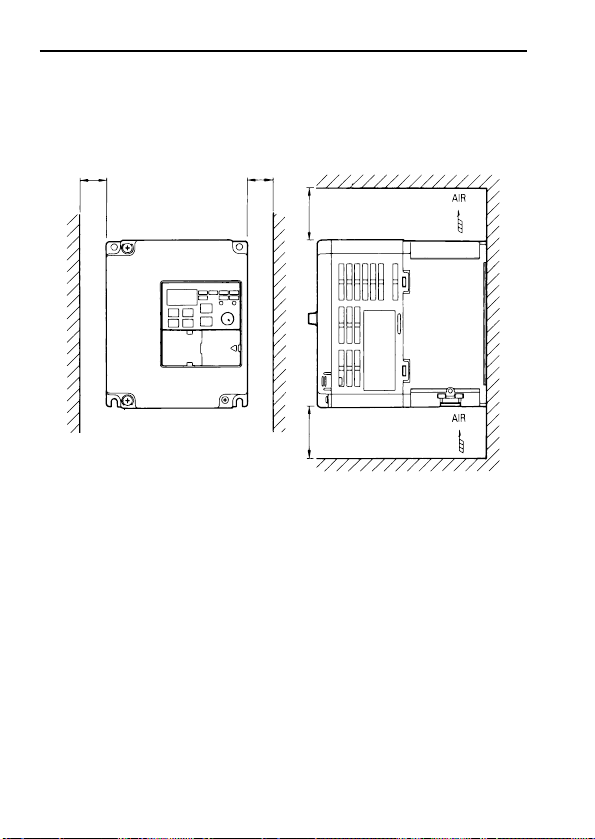
30mm
(1.18 in.)
OR MORE
30mm
(1.18 in.)
OR MORE
100mm (3.94 in.)
OR MORE
100mm (3.94 in.)
OR MORE
Mounting Dimensions
To mount the VS mini, dimensions as shown below are required.
18
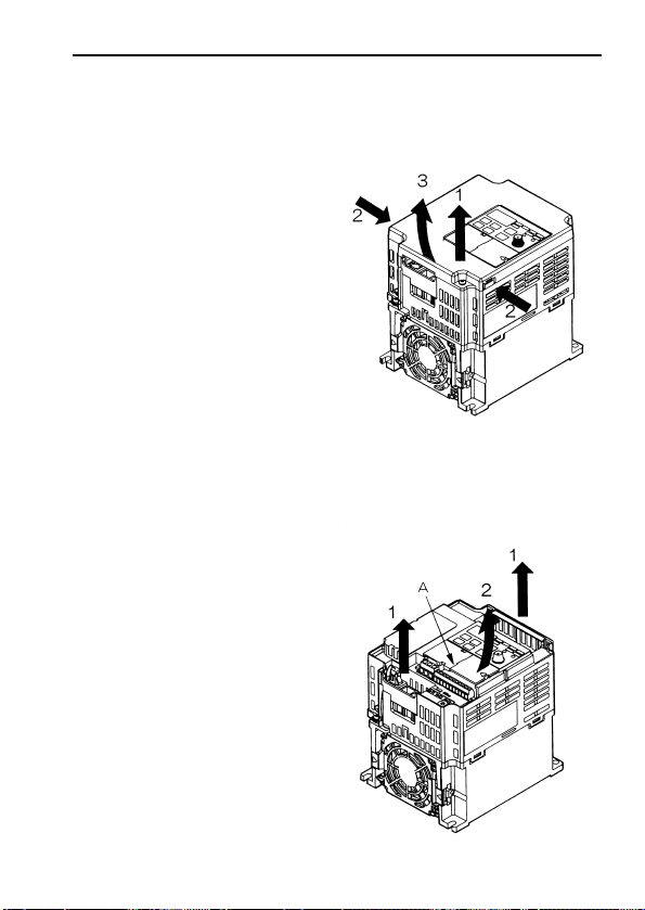
Mounting / Removing Components
19
• Removing front cover
Use a driver to loosen the screw
on the front cover surface to
direction 1 to remove it. Then
press the right and left sides to
direction 2 and lift the front cover
to direction 3.
• Mounting front cover
Insert the tab of the upper part of
the front cover into the groove of
the inverter, and press the lower
part of the front cover onto the
plastic case until the cover snaps
shut. Then, tighten the screws.
Removing and Mounting Digital Operator and Covers
• Removing option cover
After removing front cover,
remove the option cover to
direction 2 with section A as a
supporting point.
• Mounting option cover
Mount the terminal cover in the
descending order of the above
procedure for removal.
• Removing upper/bottom covers
After removing front cover, lift
the covers to direction 1.
• Mounting upper/bottom covers
Mount the front cover in the
descending order of the above
procedure for removal.

4. WIRING
Wiring Instructions
(1) Always connect the power input terminals R/L1, S/L2, and T/L3 (R/L1,
S/L2 for single-phase) and power supply via a molded-case circuit
braker (MCCB) or a fuse. Never connect them to terminals
U/T1,V/T2,W/T3, –, +1 or +2.
Refer to page 111 for recommended peripheral devices. For singlephase inverters, always use terminals R/L1 and S/L2. Never connect to
terminal T/L3.
Inverter Power Supply Connection Terminals
(2) Connect the motor wiring to terminals U/T1, V/T2 and W/T3 on the
main circuit output side (bottom of the inverter).
(3) If the wiring distance between inverter and motor is long, reduce the
inverter carrier frequency. For details, refer to “Reducing motor noise
or leakage current (n46)” on page 57.
(4) Control wiring must be less than 50m (164ft) in length and separate from
the power wiring. Use twisted-pair shielded wire when inputting the
frequency signal externally.
(5) Tighten the screws on the main circuit and control circuit terminals.
(6) Do not connect or disconnect wiring, or perform signal check while the
power supply is turned ON.
(7) For 400V class inverters, make sure to ground the supply neutral to con-
form to CE requirements.
(8) Only basic insulation to meet the requirements of protection class 1 and
overvoltage category II is provided with control circuit terminals.
Additional insulation may be necessary in the end product to conform to
CE requirements.
(9) A closed-loop connector should be used when wiring to the main circuit
terminal.
(10) Voltage drop should be considered when determining wire size.
Voltage drop can be calculated using the following equation:
Phase-to phase voltage drop (V)
= √3 × wire resistance (Ω/km) × wiring distance (m) × current (A) × 10
-3
Select a wire size so that voltage drop will be less than 2% of the normal
rated voltage.
20
200V 3-phase Input
Power Supply
Specification Product
CIMR-J7??2???
Connect to R/L1,
S/L2, T/L3
Connect to R/L1, S/L2
200V Single Input Power Supply Specification
Product
CIMR-J7??B???
Connect to R/L1, S/L2, T/L3
400V 3-phase Input
Power Supply Specification
Product
CIMR-J7??4???
21
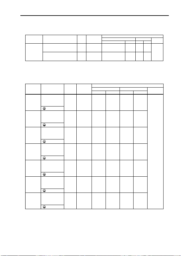
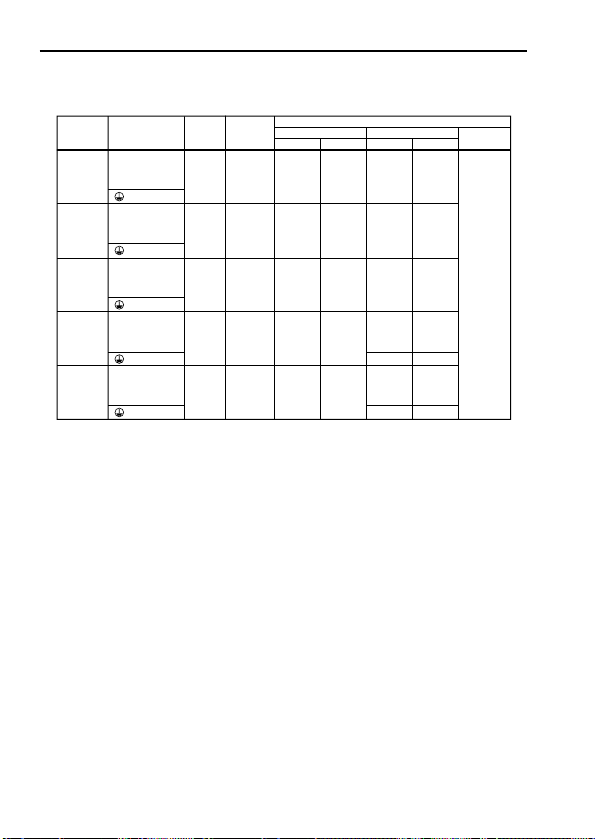
Wire and Terminal Screw Sizes
Applicable size
Recommended size
Model
Terminal
Symbol
Screw
2. Main Circuit
R/L1,S/L2,T/L3,
–,+1,+2,
U/T1,V/T2,W/T3
0.8 to 1.0
(7.1 to 8.88)
0.8 to 1.0
(7.1 to 8.88)
0.8 to 1.0
(7.1 to 8.88)
0.8 to 1.0
(7.1 to 8.88)
1.2 to 1.5
(10.7 to 13.3)
0.75 to 2
0.75 to 2
0.75 to 2
0.75 to 2
2 to 5.5
18 to 14
18 to 14
18 to 14
18 to 14
14 to 10
2
2
2
2
14
14
14
14
600V
vinyl-
sheathed
wire or
equivalent
200V Class 3-phase Input Series
Note : The wire size is set for copper wires at 75°C (160°F).
Tightening
Torque
N
•
m (Ib
•
in
)
mm
2
Wire
AWG
mm
2
AWG
Type
5.5
10
CIMRJ7AZ
20P1
R/L1,S/L2,T/L3,
–,+1,+2,
U/T1,V/T2,W/T3
CIMRJ7AZ
20P2
R/L1,S/L2,T/L3,
–,+1,+2,
U/T1,V/T2,W/T3
CIMRJ7AZ
20P4
R/L1,S/L2,T/L3,
–,+1,+2,
U/T1,V/T2,W/T3
CIMRJ7AZ
20P7
R/L1,S/L2,T/L3,
–,+1,+2,
U/T1,V/T2,W/T3
CIMRJ7AZ
24P0
M3.5
M3.5
M3.5
M3.5
M4
0.8 to 1.0
(7.1 to 8.88)
2 to 5.5 14 to 10
3.5
14
R/L1,S/L2,T/L3,
–,+1,+2,
U/T1,V/T2,W/T3
CIMRJ7AZ
22P2
M3.5
0.8 to 1.0
(7.1 to 8.88)
2 to 5.5 14 to 10
2
14
R/L1,S/L2,T/L3,
–,+1,+2,
U/T1,V/T2,W/T3
CIMRJ7AZ
21P5
M3.5
Model
Common to
all models
Terminal Symbol
MA, MB, MC
S1 to S5,SC,FS,
FR,FC,AM,AC
Screw
twisted wire
single
mm
2
mm
2
Wire
Recommended size
Applicable size
AWGAWG
0.5 to 1.25
0.5 to 1.25
twisted wire
single
0.5 to 0.75
0.5 to 1.25
20 to 16
20 to 16
20 to 18
20 to 16
Shielded
wire or
equivalent
1. Control Circuit
Tighte Torque
N • m (Ib • in)
M3
M2
Type
0.5 to 0.6
(4.44 to 5.33)
0.22 to 0.25
(1.94 to 2.21)
0.75
0.75
18
18
22
Applicable size
Recommended size
Model
Terminal
Symbol
Screw
R/L1,S/L2,T/L3,
–,+1,+2,
U/T1,V/T2,W/T3
0.8 to 1.0
(7.1 to 8.88)
0.8 to 1.0
(7.1 to 8.88)
0.8 to 1.0
(7.1 to 8.88)
0.8 to 1.0
(7.1 to 8.88)
0.75 to 2
0.75 to 2
0.75 to 2
2 to 5.5
18 to 14
18 to 14
18 to 14
14 to 10
2
2
2
14
14
14
600V
vinyl-
sheathed
wire or
equivalent
200V Class Single-phase Input Series
Tightening
Torque
N
•
m (lb
•
in
)
mm
2
Wire
AWG
mm
2
AWG
Type
CIMRJ7AZ
B0P1
R/L1,S/L2,T/L3,
–,+1,+2,
U/T1,V/T2,W/T3
CIMRJ7AZ
B0P2
R/L1,S/L2,T/L3,
–,+1,+2,
U/T1,V/T2,W/T3
CIMRJ7AZ
B0P4
R/L1,S/L2,T/L3,
–,+1,+2,
U/T1,V/T2,W/T3
CIMRJ7AZ
B0P7
M3.5
M3.5
M3.5
M3.5
0.8 to 1.0
(7.1 to 8.88)
2 to 5.5 14 to 10
5.5
10
2
14
R/L1,S/L2,T/L3,
–,+1,+2,
U/T1,V/T2,W/T3
CIMRJ7AZ
B1P5
M3.5
3.5
12
2
14
Notes : 1. The wire size is set for copper wires at 75°C (160°F).
2. Three-phase input is also available for single-phase input series.
23
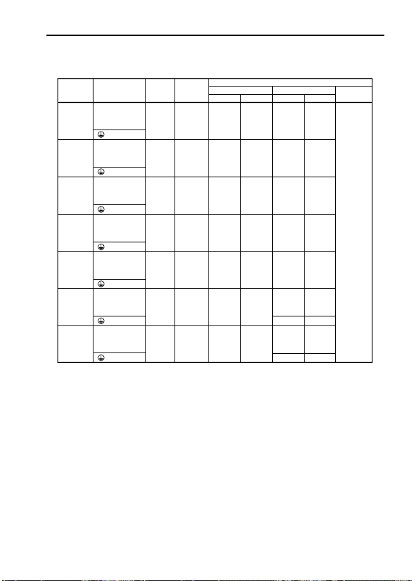
Applicable size
Recommended size
Model
Terminal
Symbol
Screw
R/L1,S/L2,T/L3,
–,+1,+2,
U/T1,V/T2,W/T3
0.8 to 1.0
(7.1 to 8.88)
0.8 to 1.0
(7.1 to 8.88)
0.8 to 1.0
(7.1 to 8.88)
0.8 to 1.0
(7.1 to 8.88)
1.2 to 1.5
(10.65 to 13.31)
2 to 5.5
2 to 5.5
2 to 5.5
2 to 5.5
2 to 5.5
14 to 10
14 to 10
14 to 10
14 to 10
14 to 10
2
2
2
2
14
14
14
14
600V
vinyl-
sheathed
wire or
equivalent
400V Class 3-phase Input Series
Note : The wire size is set for copper wires at 75°C (160°F).
Tightening
Torque
N
•
m (Ib
•
in
)
mm
2
Wire
AWG
mm
2
AWG
Type
2
3.51412
CIMRJ7AZ
40P2
R/L1,S/L2,T/L3,
–,+1,+2,
U/T1,V/T2,W/T3
CIMRJ7AZ
40P4
R/L1,S/L2,T/L3,
–,+1,+2,
U/T1,V/T2,W/T3
CIMRJ7AZ
40P7
R/L1,S/L2,T/L3,
–,+1,+2,
U/T1,V/T2,W/T3
CIMRJ7AZ
41P5
R/L1,S/L2,T/L3,
–,+1,+2,
U/T1,V/T2,W/T3
CIMRJ7AZ
44P0
M3.5
M3.5
M3.5
M3.5
M4
1.2 to 1.5
(10.65 to 13.31)
2 to 5.5 14 to 10
2
3.5
14
12
R/L1,S/L2,T/L3,
–,+1,+2,
U/T1,V/T2,W/T3
CIMRJ7AZ
43P0
M4
1.2 to 1.5
(10.65 to 13.31)
2 to 5.5 14 to 10
214
R/L1,S/L2,T/L3,
–,+1,+2,
U/T1,V/T2,W/T3
CIMRJ7AZ
42P2
M4
L1L2L
3
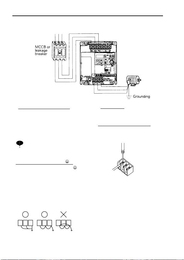
Wiring the Main Circuit
24
[Example of 3-phase,
200V class, 1.5kW
inverters]
GOOD GOOD POOR
• Main circuit input power supply
Always connect the power supply
line to
input terminals R/L1, S/L2,
and T/L3
[
R/L1, S/L2
for single-phase inverters].
Never connect them to terminal
U/T1,V/T2,W/T3, –, +1, or +2.
Otherwise the inverter may be damaged.
For single-phase inverters, always
use terminals R/L1 and S/L2. Never
connect to terminal T/L3.
•
Grounding (Use ground terminal .)
Make sure to ground the ground terminal
according to the local grounding code.
Never ground the VS mini in common
with welding machines, motors, or other
electrical equipment.
When several VS mini units are used
side by side, ground each unit as shown
in examples. Do not loop the ground
wires.
NOTE
• Inverter output
Connect the motor terminals to U/T1,
V/T2, W/T3.
Wiring the main circuit terminals
Pass the cables through wiring hole and
connect. Be sure to mount the cover in
its original position.
Connect with a Phillips (plus) screwdriver.
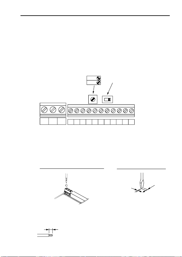
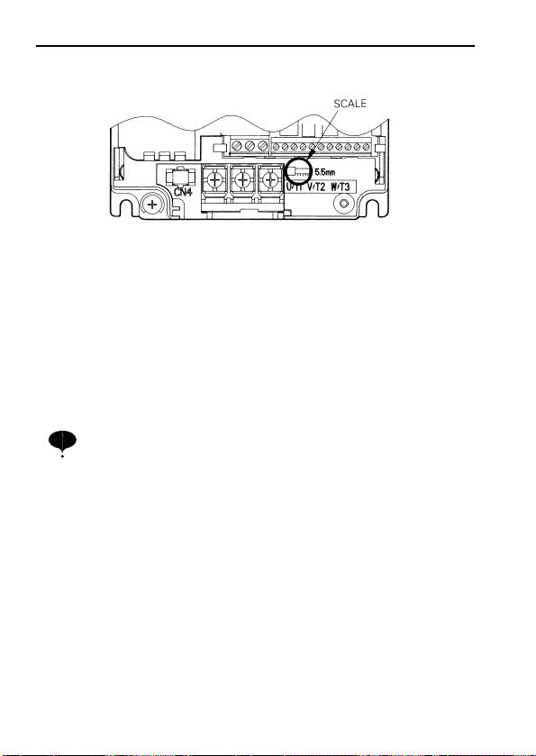
Wiring the Control Circuit
Screwdriver blade width
Insert the wire into the lower part of the terminal block and connect it tightly
with a screwdriver.
Wire sheath strip length must be 5.5mm (0.22in.).
25
* SW7 can be changed according to sequence input signal (S1 to
S5) polarity.
0V common: NPN side (factory setting)
+24 common: PNP side
Refer to page 106 for SW7.
Refer to page 67 for SW8.
• Control circuit terminals
Wiring the control circuit terminals
Pass the cable through wiring hole and connect. Be sure to mount the
covers on its original position.
MC
SW7
SW8
S1 S2 S3 S4 S5 SC
NPN
FS FR FC AM AC
MA MB
PNP
Only basic insulation is provided for the control circuit terminals.
Additional insulation may be necessary in the end product.
5.5 mm
(0.22 in.)
0.4 mm max
(0.016 in.)
2.5 mm max
(0.098 in.)
26
Wiring Inspection
After completing wiring, check the following :
▫ Wiring is proper.
▫ Wire clippings or screws are not left in the unit.
▫ Screws are securely tightened.
▫ Bare wire in the terminal does not contact other terminals.
If the FWD (REV) run command is given during the operation reference
selection (n02=1) from the control circuit terminal, the motor will start
automatically after the main circuit input power supply is turned ON.
NOTE
Open the front cover and verify that the strip length is 5.5mm. (0.22in.)

27
5. OPERATING THE INVERTER
Test Run
The inverter operates by setting the frequency (speed).
There are three types of operation modes for the VS mini :
1 Run command from the digital operator (potentiometer/digital setting).
2 Run command from the control circuit terminal.
3 Run command from communications (MEMOBUS communications)
Prior to shipping, the drive is set up to receive run command and frequency
reference from the operator. Below are instructions for running the VS mini
using the digital operator (with potentiometer). For instructions on
operation, refer to page 35.
Operation reference or frequency reference constants can be selected
separately as shown below.
Name
Run
Command
Selection
Frequency
Reference
Selection
Constant
n02 = 0 --- Enables operator RUN, STOP/RESET
= 1 --- Enables control circuit terminal run/stop
= 2 --- Enables communications (MEMOBUS communications)
n03 = 0 --- Enables operator volume
= 1 --- Enables frequency reference 1 (constant n21)
= 2 --- Enables voltage reference (0 to 10V) of control circuit
terminal
= 3 --- Enables current reference (4 to 20mA) of control circuit
terminal
= 4 --- Enables current reference (0 to 20mA) of control circuit
terminal
= 6 --- Enables communications (MEMOBUS communications)
28
Operation Steps
Operator
Display
12-LED
Display
Status
Indicator
LED
RUN ALARM
RUN ALARM
RUN ALARM
Status indicator lamp
: ON
: Blinking : OFF
1. Turn the potentiometer fully to the left before
turning the power ON.
2. F/R blinks.
Select FWD/REV run using keys.
Never select REV when reverse run is
prohibited.
3. Press DSPL to blink FREF. Then press RUN.
4.
Operates the motor by turning the
potentiometer to the right. (Frequency
reference corresponds to the potentiometer
0.0
(Forward)
or
(Reverse)
0.0 to 60.0
Minimum
output
frequency is
1.5Hz
FREF
NOTE
0.0
RUN ALARM
F/R
FREF
FREF
NOTE
If the potentiometer is switched rapidly,
the motor also accelerates or decelerate
rapidly corresponding to the potentiometer
movement. Pay attention to load status
and switch the potentiometer with the
speed not to affect motor movement.
Operation Check Points
▫ Motor rotates smoothly.
▫ Motor rotates in the correct direction.
▫ Motor does not have abnormal vibration or noise.
▫ Acceleration or deceleration is smooth.
▫ Current matching the load flows.
▫ Status indicator LEDs and digital operator display are correct.
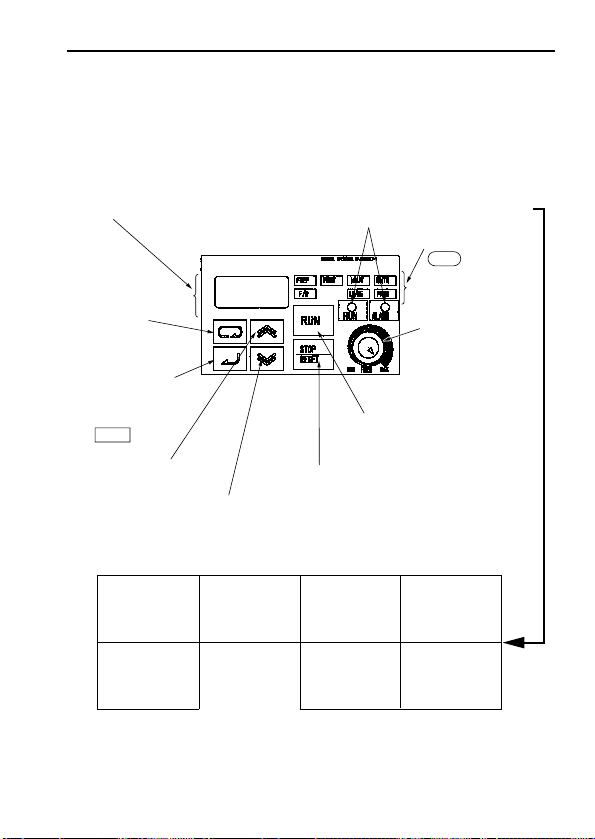
Operating the Digital Operator
All functions of the VS mini are set by the digital operator. Below are
descriptions of the display and keypad sections.
29
DIGITAL OPERATOR
Press to switch
between
function LEDs.
Press to increase
constant no./data
value.
Press to decrease
constant no./data
value.
Function display LEDs (Color in parenthesis indicates the color of LED.
)
Press to stop the motor.
(Press to reset at faults.)
Press to run
the motor.
Frequency setting
potentiometer
Changes frequency
setting according to
potentiometer.
Data display section Status indicator
FREF
Frequency reference
setting/monitoring
(GREEN)
FOUT
Output frequency
monitor
(GREEN)
IOUT
Output current
monitor
(GREEN)
F/R
Operator RUN
command FWD/REV
selection
(GREEN)
PRGM
Constant no./data
(RED)
MNTR
Multi-function
monitor
(GREEN)
LO/RE
LOCAL/REMOTE
Selection
(RED)
Function display LEDs
LED switches to another
function each time
DSPL is pressed.
The displayed data can
be changed.
Press to enter the
constant data.
(Displays the constant
data when
selecting constant no.
by PRGM LED.)
30
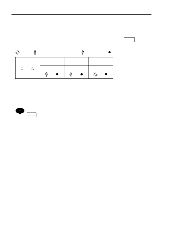
Description of Status Indicator LEDs
There are two LEDs on the middle right section of the face of the VS mini.
The inverter status is indicated by various combinations of ON, BLINKING
and OFF LEDs. RUN indicator and status indicator on the button
have the same function.
For details on how the status indicator LEDs function at inverter faults, refer
to Section 8 “FAULT DIAGNOSIS AND CORRECTIVE ACTIONS” on
page 87. If a fault occurs, the ALARM LED lights.
The fault can be reset by turning ON the fault reset signal (or pressing
key on the digital operator) with the operation signal OFF or
by turning OFF the power supply. If the operation signal is ON, the
fault cannot be reset by the fault reset signal.
STOP
RESET
RUN
: ON
RUN ALARM
(Green)
(Red)
Operation Ready
(During Stop)
RUN ALARM
Ramp to Stop
RUN ALARM RUN ALARM
: BLINKING : OFF: BLINKING (Long Blinking)
Normal Operation
NOTE

31
LED Description
By pressing on the digital operator, each of the function LEDs can be
selected.
The following flowchart describes each function LED.
DSPL
If the VS mini loses
power while in one
of these modes, it
will return to this
mode once power is
restored.
Power ON
FREF
FOUT
IOUT
MNTR
F/R
DSPL
DSPL
DSPL
DSPL
DSPL
Frequency reference setting/monitor (Hz)
Sets VS mini operation speed.
Output frequency monitor (Hz)
Displays frequency that VS mini is currently
outputting.
Setting disabled.
Output current monitor (A)
Displays current that VS mini is currently
outputting.
Setting disabled.
Multi-function monitor
Description of the selected monitor is
displayed.
(Refer to pages 32 and 33 for details.)
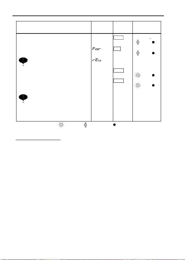
FWD/REV run selection
Sets the motor rotation direction when
run command is given by the digital operator.
Setting can be changed by or key.
FO (forward run) EV (reverse run)
<
<
Monitor No.
U01: Frequency reference (FREF)
U02: Output frequency (FOUT)
U03: Output current (IOUT)
U04: Output voltage reference (Unit: 1V)
U05: DC voltage (Unit: 1V)
U06: Input terminal status
U07: Output terminal status
U09: Fault history
U10: Software No.
U15: Data reception error

32
LO/RE
PRGM
DSPL
DSPL
LOCAL / REMOTE Selection
Constant No. / data
Sets and changes data using
constant No. (Refer to page 34.)
FREF
Return to
This function switches the operation; operation
using the digital operator including frequency
setting with potentiometer, or that using the input
terminals or through communications
Setting can be changed by or key.
(Local) (Remote)
<
<
Multi-Function monitor
Press key. When is ON, data
can be displayed by selecting monitor No.
[Example] Monitoring Output Voltage Reference
DSPL MNTR
MNTR
U04
ENTER
MNTR
DSPL
ENTER
or
Select U04 by
pressing
or key.
^
^
Output voltage reference
is displayed.
MNTR
• Selecting monitor
DSPL
IOUT
DSPL
F/R
200

33
Constant
No.
Name Description
U01
U02
U03
U04
U05
U06
U07
U09
U10
Frequency reference
(FREF)
Output frequency
(FOUT)
Output current
(IOUT)
Output voltage
DC voltage
Input terminal status
Output terminal status
Fault history
Software No.
Frequency reference can be monitored.
(Same as FREF)
Output frequency can be monitored.
(Same as FOUT)
Output current can be monitored.
(Same as IOUT)
Output voltage can be monitored.
Main circuit DC voltage can be monitored.
Input terminal status of control circuit terminals
can be monitored.
Output terminal status of control circuit
terminals can be monitored.
Last four fault history is displayed.
Software No. can be checked.
Hz
Hz
A
V
V
---
---
---
---
U15 Data reception error
Contents of MEMOBUS communication data
reception error can be checked.
(contents of transmission register No. 003DH
are the same)
---
• Monitoring
Following items can be monitored by U- constants.
1: Terminal S1 is “closed.”
Input terminal status
1: Terminal S2 is “closed.”
1: Terminal S3 is “closed.”
1: Terminal S4 is “closed.”
1: Terminal S5 is “closed.”
1: Terminal MA-MC is “closed.”
Output terminal status
Not used
Not used
Input/Output terminal status

34
Setting and referring constants
Following shows how to select and change constants.
LO/RE
PRGM
DSPL
DSPL
PRGM
ENTER
PRGM PRGM
ENTER
PRGM
PRGM
FREF
REMOTE/LOCAL
selection
Constant
No./
data
n02
Run command
selection
After
1 sec
Initial setting:0
operator reference
Set to 1
Control circuit
terminal reference
(blinking at changing)
• Setting n02 (Run command selection)
Data setReturn to
constant No.
display
600
N01
LO
N02 0
N02
1
1
Clearing fault history
Set constant n01 to 6 to clear fault history. Set data returns to its
initial value after completion of 6 setting.
Note: Constant initialize (n01=12, 13) clears the fault history.
Fault history display method
Fault description is displayed when U09 is selected.
(Example)
??? : Fault description
"---" is displayed if there is no fault.
(Refer to page 87 for details.)

35
NOTE
Simple Data Setting
Potentiometer setting (Refer to 5. OPERATING THE INVERTER) and
digital setting are both available for simple accel/decel operation of the VS
mini.
Frequency reference by potentiometer signal is set with initial setting
(n03=0).
Factory setting of the model with operator (without potentiometer) is set by
digital operator (n03=1).
Following is an example in which the function LEDs are used to set
frequency reference, acceleration time, deceleration time, and motor
direction.
Operation Steps
1. Turn ON the power supply.
7. Press to stop.
STOP
Operator
Display
LED
Display
Status Indicator
LED
2. Set constant n03 to 1.
3. Set the following constants.
4. Select forward or reverse run by
pressing q or w key.
5.
Set the reference by pressing q or w
key.
6. Press .
15.0
5.0
0.0
1
60.0
0.0 to 60.0
FREF
PRGM
FOUT
PRGM
n16 : 15.0 (acceleration time)
n17 : 5.0 (deceleration time)
Examine the application.
(Never select REV when
reverse run is prohibited.)
RUN
FOUT
FREF
F/R
60.0 to 0.0
(Forward)
(Reverse)
or
Status indicator lamp : BLINKING (Long Blinking) : BLINKING : OFF
RUN ALARM
RUN ALARM
RUN ALARM
RUN ALARM
RUN ALARM
RUN ALARM
RUN ALARM

36
6. PROGRAMMING FEATURES
Factory settings of the constants are shown as in the tables.
Constant Set-up and Initialization
The following table describes the data which can be set or read when n01 is
set.
Unused constants among n01 to n79 are not displayed.
“EMM” appears on the LED display for one second and the set data returns to its initial
values in the following cases :
(1) The set values of input terminal function selection 2 to 5 (n36 to n39) are the same.
(2) If the following conditions are not satisfied in the V/f pattern setting :
Max. output frequency (n09) Max. voltage output frequency (n11)
> Mid. output frequency (n12)
Min. output frequency (n14)
For details, refer to “Adjusting torque according to application” (V/f pattern setting) on page 37.
(3) If the following conditions are not satisfied in the Jump frequency setting :
Jump frequency 2 (n50) Jump frequency 1 (n49)
(4) If Frequency reference lower limit (n31) Frequency reference upper limit (n30)
(5) If motor rated current (n32) 120% of inverter rated current
Constant selection/initialization (n01)
n01 Setting
0 n01
1
6
7
12
13
* Excluding setting disabled constants.
†
NOTE
Constant that can be set Constant that can be referred
n01 to n79*
Fault history cleared
Not used
Initialize
Initialize (3-wire sequence)
n01 to n79
n01 to n79
†
Refer to page 63.

37
Selecting V/f pattern
Adjust motor torque by using “V/f pattern” and “full-range automatic torque
boost”.
• V/f pattern setting
Set V/f pattern by n09 to n15 as described below. Set each pattern when
using a special motor (high-speed motor, etc.) or when requiring special
torque adjustment of machine.
Be sure to satisfy the following
conditions for the setting of n09 to
n15.
n14 n12 < n11 n09
If n14 = n12 is set, the set value of n13
is disabled.
Adjusting torque according to application
V: (VOLTAGE)
n10
n13
n15
0
n14 n12 n11 n09
Constants
No.
n09
n10
n11
n12
n13
n14
n15
* For 400-volt class inverters
Name Unit Setting range
Max. output frequency
Max. voltage
Max. voltage output
frequency (base frequency)
Mid. output frequency
Mid. output
frequency voltage
Min. output frequency
Min. output
frequency voltage
f
(FREQUENCY)
0.1Hz
1V
0.1Hz
0.1Hz
1V
0.1Hz
1V
Initial
50.0 to 400.0Hz 50.0Hz
1 to 255V
(1 to 510V)
0.2 to 400.0Hz
(1 to 510V)*
0.1 to 10.0Hz
(1 to 100V)*
*
1 to 399Hz
1 to 255V
1 to 50V
Setting
200V
(400V)
50.0Hz
1.3Hz
12V
(24V)
1.3Hz
12V
(24V)

38
• Typical setting of V/f pattern
Set the V/f pattern according to the application as described below. For
400V class, the voltage values (n10, n13, and n15) should be doubled.
When running at a frequency exceeding 50Hz/60Hz, change the maximum
output frequency (n09).
Note: Be sure to set the maximum output frequency according to the motor characteristics.
(1) For general-purpose applications
(2) For fans/pumps
(3) For applications requiring high starting torque
Increasing voltage of V/f pattern increases motor torque, but an excessive
increase may cause motor overexcitation, motor overheat or vibration.
Note : n12 is to be set to motor rated voltage.
Constant
n09
n10
n11
n12
n13
n14
n15
Setting
60.0
200
60.0
1.5
12
1.5
12
Constant Setting
50.0
200
50.0
1.3
12
1.3
12
n09
n10
n11
n12
n13
n14
n15
Constant Setting
60.0
200
60.0
30.0
50
1.5
10
n09
n10
n11
n12
n13
n14
n15
Constant Setting
50.0
200
50.0
25
50.0
1.3
10
n09
n10
n11
n12
n13
n14
n15
Constant Setting
60.0
200
60.0
3.0
24
1.5
18
n09
n10
n11
n12
n13
n14
n15
Constant Setting
50.0
200
50.0
2.5
24
1.3
18
n09
n10
n11
n12
n13
n14
n15
Motor Specification : 60Hz
Motor Specification : 60Hz Motor Specification : 50Hz
Motor Specification : 60Hz Motor Specification : 50Hz
Motor Specification : 50Hz
(Factory setting)
V
200
12
1.5 60 f
V
200
12
1.3 50 f
V
200
50
10
1.5 30 60 f
V
200
50
10
1.3 25 50 f
V
200
24
18
1.5 3 60 f
V
200
24
18
1.3 2.5 50 f

39
• Full-range automatic torque boost
Motor torque requirement changes according to load conditions. Fullrange automatic torque boost adjusts voltage of V/f pattern according to
the requirement. The VS mini automatically adjusts the voltage during
constant-speed operation as well as during acceleration.
The required torque is calculated by the inverter.
This ensures tripless operation and energy-saving effects.
Operation
Normally, no adjustment is necessary for torque compensation gain (n63
factory setting : 1.0). When the wiring distance between the inverter and the
motor is long, or when the motor generates vibration, change the automatic
torque compensation gain. In these cases, set the V/f pattern (n09 to n15).
Output voltage Torque compensation gain (n63)
Required torque
n11
=60Hz
n10
=200V
n09
=90Hz
BASE POINT
CONSTANT TORQUE
CONSTANT OUTPUT OR
VARIABLE OUTPUT
When operating with frequency larger than 60Hz/50Hz, change only max.
output frequency (n09).
f (FREQUENCY)
Required torque Increase voltage
V
(VOLTAGE)

40
Switching LOCAL/REMOTE Modes
The following functions can be selected by switching the LOCAL or
REMOTE mode. To select RUN/STOP commands or frequency
reference, change the mode in advance depending on the following
applications.
• LOCAL mode : Enables the digital operator for RUN/STOP
commands and FWD/REV run commands.
Frequency reference can be set by volume or .
•
REMOTE mode
: Run by the n02 setting (run command selection).
Frequency reference can be set by n03 (frequency
reference selection) setting.
FREF
How to select LOCAL/REMOTE modes
When LOCAL/REMOTE
switching function is not set
for multi-function input
selection
When LOCAL/REMOTE
switching function is set at
multi-function input selection
Select Lo for operator
selection.
Select rE for operator
selection.
Set multi-function
input terminal is turned
ON.
Set multi-function
input terminal is turned
OFF.
LOCAL mode REMOTE mode
LO/RE LO/RE
(When 17 is set to
any of constants
n36 to n39)
(When 17 is not set
to any of constants
n36 to n39)

41
Selecting Run/Stop Commands
Refer to Switching LOCAL / REMOTE Modes (page 40) to select
either the LOCAL mode or REMOTE mode.
Operation method (RUN / STOP commands, FWD / REV run
commands) can be selected by the following method.
LOCAL mode
When Lo (local mode) is selected for digital operator ON mode,
or when LOCAL / REMOTE switching function is set and the input
terminals are turned ON, run operation is enabled by the or of
the digital operator, and FWD/REV run is enabled by ON mode
(using or key).
is not effective when local / remote switching function is
selected for multi-function input selection.
REMOTE mode
• Select remote mode.
There are following two methods to select remote mode.
1. Select rE (remote mode) for selection.
2. When the local / remote switching function is selected for multi-
function input selection, turn OFF the input terminal to select remote
mode.
• Select operation method by setting the constant n02.
n02=0: Enables the digital operator (same with local mode)
=1: Enables the multi-function input terminal (see fig. below)
=2: Enables communications (refer to page 74) (When option card
is installed)
• Example for using the multi-function input terminal as operation
reference (two-wire sequence)
For example of three-wire sequence, refer to page 63.
Operating (RUN / STOP commands) by communications
(When option card is installed)
Setting constant n02 to 2 in REMOTE mode can give RUN/STOP
commands by communication (MEMOBUS communications).
For details, refer to page 74.
IM
S1
S2
SC
FWD RUN/STOP
REV RUN/STOP
n02 : 1 (Initial setting : 0)
n36 : 2
LO / RE
LO / RE
LO / RE
F / R
RUN
STP
<
<

42
Selecting Frequency Reference
Frequency reference can be selected by the following methods.
Setting by operator
Select REMOTE or LOCAL mode in advance. For the method for
selecting the mode, refer to page 40.
LOCAL mode
Select command method by constant n07.
n07=0 :
Enables the setting by potentiometer on digital operator (initial setting).
Factory setting of the model with digital operator (without
potentiometer) is n07=1.
=1 : Enables the digital setting by digital operator, setting value is
stored in constant n21 (frequency reference 1).
• Digital setting by digital operator
Input frequency while FREF is lit (press ENTER after setting the numeric
value).
Frequency reference setting is effective when 1 is set to constant n08
instead of pressing ENTER key.
n08=0 :
Enables frequency reference setting by ENTER key (initial setting).
=1 : Disable frequency reference setting by ENTER key.
REMOTE mode
Select command method by constant n03.
n03=0 :
Enables frequency reference setting by potentiometer on digital
operator (initial setting). Initial setting of the model with digital
operator (without potentiometer) is n03=1.
=1 : Frequency reference 1 effective. (constant n21)
=2 : Voltage reference (0 to 10V) (See the figure below)
=3 : Current reference (4 to 20mA) (Refer to page 67)
=4 : Current reference (0 to 20mA) (Refer to page 67)
=6 : communication (Refer to page 74)
Example of frequency reference by voltage signal
IM
FS
FREQUENCY
SETTING POWER
+12V, 20mA
FR
FC(0V)
2KΩ
MASTER SPEED
FREQUENCY
REFERENECE
(0 TO +10V)
n03 = 2 (Factory setting : 0)

43
Setting Operation Conditions
“Reverse run disabled” setting does not accept a reverse run command from
the control circuit terminal or digital operator. This setting is used for
applications where a reverse run command can cause problems.
By combining frequency reference and input terminal function selections,
up to 9 steps of speed can be set.
8-step speed change
n02=1 (operation mode selection )
n36=2 (Multi-function contact input terminal 2)
n03=1 (
Frequency reference
selection )
n37=6 (Multi-function contact input terminal 3)
n21=25.0Hz (
Frequency reference 1)n38=7 (Multi-function contact input terminal 4)
n22=30.0Hz (
Frequency reference 2)
n39=8 (Multi-function contact input terminal 5)
n23=35.0Hz (
Frequency reference 3
)
n24=40.0Hz (
Frequency reference 4
)
n25=45.0Hz (
Frequency reference 5
)
n26=50.0Hz (
Frequency reference 6
)
n27=55.0Hz (
Frequency reference 7
)
n28=60.0Hz (
Frequency reference 8
)
Reverse run prohibit (n05)
Multi-step speed selection
When all multi-function
reference inputs are OFF,
frequency reference selected
by constant n03 (frequency
reference selection) becomes
effective.
NOTE
FWD
RUN/STOP
REV RUN/STOP
MULTI-STEP
SPEED REF 1
MULTI-STEP
SPEED REF 2
MULTI-STEP
SPEED REF 3
S1
S2
S3
S4
S5
SC
n36=2 (Input terminal S2) Initial Setting
n37=6 (Input terminal S3) Change the setting to 6.
n38=7 (Input terminal S4) Change the setting to 7.
n39=8 (Input terminal S5) Change the setting to 8.
Setting
0
1
Description
Reverse run enabled.
Reverse run disabled.

44
By inputting a jog command and then a forward (reverse) run command,
operation is enabled at the jog frequency set in n29. When multi-step speed
references 1, 2, 3 or 4 are input simultaneously with the jog command, the
jog command has priority.
ON
ONON ON ON
ONON
ON
TIME
(n28) 60.0 Hz
(n27) 55.0 Hz
(n26) 50.0 Hz
(n25) 45.0 Hz
(n24) 40.0 Hz
(n23) 35.0 Hz
(n22) 30.0 Hz
(n21) 25.0 Hz
FREQUENCY
REFERENCE
FWD (REV) RUN/STOP
MULTI-STEP SPEED REF. 1
(TERMINAL S3)
MULTI-STEP SPEED REF. 2
(TERMINAL S4)
MULTI-STEP SPEED REF. 3
(TERMINAL S5)
Operating at low speed
Name
Jog frequency
Jog command
Constant No.
n29
n36 to n39
Factory setting : 6.0Hz
Set to “10” for any constant.
Setting

45
To provide frequency reference by analog input of control circuit terminal FR or
FC, the relationship between analog input and frequency reference can be set.
FREQURNCY REFERNCE
0V
(4mA)
(0mA)
10V
(20mA)
(20mA)
MAX. OUTPUT FREQUENCY
GAIN
100
MAX. OUTPUT FREQUENCY
BIAS
100
( ) indicates the value when current
reference input is selected.
Typical Setting
• Frequency reference gain (n41)
The analog input voltage value for the max (10V). output frequency (n09)
can be set in units of 1% (max. output frequency n09=100%)
*
Factory setting : 100%
• Frequency reference bias (n42)
The frequency reference provided when analog input is 0V (4mA or 0mA)
can be set in units of 1%. (max. output frequency n09=100%)
*
Factory setting : 0%
• To operate the inverter with frequency reference of 0% to 100% at 0 to 5V
input
MAX. FREQUENCY (100%)
0%
0V 5V 10V
Gain n41 = 200
Bias n42 = 0
Adjusting speed setting signal

46
• To operate the inverter with frequency reference of 50% to 100% at 0 to
10V input
MAX. FREQUENCY (100%)
50%
0V 10V
Gain n41 = 100
Bias n42 = 50

47
Adjusting frequency upper and lower limits
• Frequency reference upper limit (n30)
Sets the upper limit of the frequency reference
in units of 1%.
(n09: Max. output frequency = 100%)
Factory setting: 100%
• Frequency reference lower limit (n31)
Sets the lower limit of the frequency reference
in units of 1%.
(n09: Max. output frequency = 100%)
When operating at frequency reference 0,
operation is continued at the frequency
reference lower limit.
However, when frequency reference lower
limit is set to less than the min. output
frequency (n14), operation is not performed.
Factory setting: 0%
Using two accel/decel times
* When “deceleration to a stop” is selected (n04 = 0).
By setting input terminal function selection (either of n36 to n39) to “11
(accel/decel time select)”, accel/decel time is selected by turning ON/OFF the
accel/decel time select (terminal S2 to S5).
At OFF : n16 (accel time 1)
n17 (decel time 1)
At ON : n18 (accel time 2)
n19 (decel time 2)
INTERNAL
FREQUENCY
REFERENCE
FREQUENCY
UPPER LIMIT
(n30)
SET FREQUENCY REFERENCE
FREQUENCY
LOWER LIMIT
(n31)
FORWARD (REVERSE)
RUN COMMAND
MULTI-STEP
SPEED REFERENCE
ACCEL/DECEL
TIME SELECTION
(TERMINAL S2 TO S5)
OUTPUT
FREQUENCY
ACCEL
TIME 1
(n16)
DECEL
TIME 1
(n17)
ACCEL
TIME 2
(n18)
DECEL
TIME 2*
(n19)
DECEL
TIME 1*
(n17)
TIME
ON
ON
ON

48
• Accel time
Set the time needed for output frequency to reach 100% from 0%.
• Decel time
Set the time needed for output frequency to reach 0% from 100%.
(Maximum output frequency n09=100%)
When momentary power loss occurs, operation restarts automatically.
* Hold the operation command to continue the operation after recovery from a momentary
power loss.
† When 2 is selected, operation restarts if power supply voltage reaches its normal level while
control power supply is held. No fault signal is output.
Automatic restart after momentary
power loss (n47)
Description
Setting
Setting
Continuous operation after momentary power loss
Continuous operation after momentary power loss
0
0
not provided.
not provided.
Continuous operation after power recovery within
Continuous operation after power recovery within
1*
momentary power loss ridethru time
Continuous operation after power recovery (Fault
Continuous operation after power recovery (Fault
2*†
2*†
output not provided)
output not provided)
Description

49
To prevent shock at machine start/stop, accel/decel can be performed in Scurve pattern.
Note : S-curve characteristic time is the time from accel/decel rate 0 to a regular accel/decel rate
determined by the set accel/decel time.
Soft-start characteristics (n20)
The following time chart shows FWD/REV run switching at deceleration to
a stop.
DC INJECTION BRAKING
TIME AT STOP
n53
MIN. OUTPUT FREQUENCY
MIN. OUTPUT
FREQUENCY n14
DECELERATION
DECELERATION
ACCELERATION
FORWARD RUN COMMAND
REVERSE RUN COMMAND
OUTPUT FREQUENCY
ACCELERATION
n14
S-curve characteristics in
FREQUENCY
REFERENCE
OUTPUT
FREQUENCY
S-CURVE CHARACTERISTIC TIME (Tsc)
OUTPUT
FREQUENCY
TIME
Setting
0
1
2
3
S-curve characteristic time
S-curve characteristic not provided
0.2 second
0.5 second
1.0 second

If an excessive load is applied to the machine, output current increase can be
detected to output alarm signals to multi-function output terminals MA and
MB.
To output an overtorque detection signal, set output terminal function
selection n40 to “overtorque detection” [Setting:6 (NO contact) or 7 (NC
contact)].
50
Torque detection
*
Overtorque detection release width (hysterisis) is set at approx. 5% of inverter
rated current.
MOTOR CURRENT
n60
MULTI-FUNCTION OUTPUT SIGNAL
(OVERTORQUE DETECTION SIGNAL)
TERMINAL MA, MB
* *
TIME
ONON
n61n61

51
• Overtorque detection function selection (n59)
(1) To detect overtorque at accel/decel, set to 3 or 4.
(2) To continue the operation after overtorque detection, set to 1 or 3.
During detection, the operator displays “OL3” alarm (blinking).
(3) To halt the inverter by a fault at overtorque detection, set to 2 or 4. At
detection, the operator displays “OL3” fault (ON).
• Overtorque detection level (n60)
Sets the overtorque detection current level in units of 1%. (Inverter rated
current = 100%)
Factory setting: 160%
• Overtorque detection time (n61)
If the time when motor current exceeds the overtorque detection level (n60)
is longer than overtorque detection time (n61), the overtorque detection
function operates.
Factory setting : 0.1sec.
Overtorque detection not provided
Detected during constant-speed running,
and operation continues after detection.
Setting
0
1
2
3
4
Description
Detected during constant-speed running,
and operation stops during detection.
Detected during running,
and operation continues after detection.
Detected during running,
and operation stops during detection.

Effective when either of output terminal function selection n40 is set to “frequency detection” (setting: 4 or 5). “Frequency detection” turns ON when output frequency is higher or lower than the frequency detection level (n58).
•
Frequency detection 1
(Output frequency Frequency detection level n58)
(Set n40 to “4.”)
•
Frequency detection 2
(Output frequency Frequency detection level n58)
(Set n40 to “5.”)
52
Frequency detection (n58)
FREQUENCY DETECTION
LEVEL [Hz] (n58)
OUTPUT
FREQUENCY
FREQUENCY
DETECTION
SIGNAL
ON
RELEASE
WIDTH
–2Hz
RELEASE
OUTPUT
FREQUENCY
FREQUENCY
DETECTION
SIGNAL
WIDTH
+2Hz
FREQUENCY
DETECTION
LEVEL (Hz)
(n58)
ONON

This function allows the prohibition or “jumping” of critical frequencies so
that the motor can operate without resonance caused by machine systems.
This function is also used for dead band control. Setting the value to 0.0Hz
disables this function.
Set prohibited frequency 1 or 2 as follows :
Operation is prohibited within jump frequency range.
However, motor operates without jumping during accel/decel.
Sets the inverter to restart and reset fault detection after a fault occurs.
The number of self-diagnosis and retry attempts can be set at n48 up to 10.
The inverter automatically restarts after the following faults occur :
OC (overcurrent)
GF (ground fault)
OV (overvoltage)
The number of retry attempts are cleared to 0 in the following cases :
(1) If no other fault occurs within 10 minutes after retry
(2) When the fault reset signal is ON after the fault is detected
(3) Power supply is turned OFF
53
Jump frequencies (n49 to n51)
OUTPUT FREQUENCY
FREQUENCY REFERENCE
n51
n49
n50
n51
Continuing operation by automatic fault reset (n48)
n49 n50
If this condition is not satisfied
the inverter displays
EMM
for
one second and restores the
data to original settings.

54
To operate coasting motor without trip, use the speed search command or
DC injection braking at start.
• Speed search command
Restarts a coasting motor without stopping it. This function enables
smooth switching between motor commercial power supply operation and
inverter operation.
Set input terminal function selection (n36 to n39) to “14” (search
command from maximum output frequency) or “15” (search command
from set frequency).
Build a sequence so that FWD (REV) run command is input at the same
time as the search command or after the search command. If the run
command is input before the search command, the search command
becomes disabled.
• Time chart at search command input
• DC injection braking at start (n52, n54)
Restarts a coasting motor after stopping it. Set the DC injection braking
time at start in n54 in units of 0.1 second. Set DC injection braking current
in n52 in units of 1% (inverter rated current =100%). When the setting of
n54 is “0”, DC injection braking is not performed and acceleration starts
from the minimum output frequency.
When n52 is set to 0, acceleration starts from
the minimum output frequency after the
baseblocking for n54 setting time.
Operating coasting motor without trip
FWD (REV) RUN COMMAND
SEARCH COMMAND
MAX. OUTPUT FREQUENCY OR
FREQUENCY REFERENCE AT
RUN COMMAND INPUT
OUTPUT FREQUENCY
MIN. BASEBLOCK
TIME (0.5s)
ON
SPEED SEARCH OPERATION
ON
AGREED SPEED
DETECTION
MIN. OUTPUT
FREQUENCY
n14
n54
DC INJECTION BRAKING
TIME AT START

55
To hold acceleration or deceleration, input accel/decel hold command. The
output frequency is maintained when the accel/decel hold command is input
during acceleration or deceleration.
When the stop command is input during accel/decel prohibition command
input, accel/decel hold is released and operation ramps to stop.
Set multi-function input terminal selection (n36 to n39) to 16 (accel/decel
hold command).
Time chart at accel/decel hold command input
Note : When the FWD (REV) run command is input along with the accel/decel hold command,
the motor does not operate. However, when frequency reference lower limit (n31) is set
greater than or equal to min. output frequency (n14), the motor operates at frequency
reference lower limit (n31).
Holding accel/decel temporarily
FWD (REV)
RUN COMMAND
ACCEL/DECEL
HOLD COMMAND
FREQUENCY
REFERENCE
OUTPUT
FREQUENCY
FREQUENCY
AGREED
SIGNAL
ON
ON
ONONON
ON

56
Selects to output either output frequency or output current to analog output
terminals AM-AC for monitoring.
In initial setting, analog voltage of approx. 10V is output when output frequency
(output current) is 100%.
Used to adjust analog output gain.
Set the analog output voltage at 100% of output frequency (output current).
Frequency meter displays 0 to 60Hz at 0 to 3V.
Using frequency meter or ammeter (n44)
SettingSetting
Description
Output frequency
Output current
0
1
Calibrating frequency meter or
ammeter (n45)
AM
AC
0 TO 10VDC
FREQUENCY METER
FM
OUTPUT FREQUENCY
(OUTPUT CURRENT)
Analog monitor gain
can be set by n45
100%
0 10V
ANALOG OUTPUT
FM
OUTPUT FREQUENCY
(OUTPUT CURRENT)
100%
n45=0.30
FACTORY SETTING
n45=1.00
ANALOG OUTPUT
3V 10V
AM
AC
FREQUENCY METER/AMMETER
(3V 1mA FULL-SCALE)
n45
FM
n45 Setting
10V = 3V
0.30
·
·
·
Output frequency becomes
100% at this value.

57
Set inverter output transistor switching frequency (carrier frequency).
Reducing motor noise or leakage current (n46)
Setting values 7, 8, or 9 multiplies output frequency according to output
frequency value.
fc=CARRIER FREQUENCY
2.5kHz
1.0kHz
83.3Hz 208.3Hz
fout=OUTPUT
FREQUENCY
fout=OUTPUT
FREQUENCY
fout=OUTPUT
FREQUENCY
fc=12 fout
fc=CARRIER FREQUENCY
2.5kHz
1.0kHz
41.6Hz 104.1Hz
fc=24 fout
fc=CARRIER FREQUENCY
2.5kHz
1.0kHz
27.7Hz 69.4Hz
fc=36 fout
n46=7
n46=8
n46=9
Setting
7
8
9
1
2
3
4
Carrier Frequency
12 fout
24 fout
36 fout
2.5
5.0
7.5
10.0
(Hz)
(Hz)
(Hz)
(kHz)
(kHz)
(kHz)
(kHz)
Metallic Noise
from Motor
Higher
Not
audible
Noise and Current
Leakage
Smaller
Larger

58
Factory setting varies according to inverter capacity (kVA).
NOTE
(1) Reduce continuous output current when changing carrier frequency to 4
(10 kHz) for the 200V class (1.5kW or more) and 400V class
inverters. Refer to the table above for the reduced current.
[Operation Condition]
• Input power supply voltage : 3-phase 200 to 230V (200V class)
Single-phase 200 to 240V (200V class)
3-phase 380 to 460V (400V class)
• Ambient temperature : -10 to +50°C (14 to 122°F)
(Protection structure: open chassis type
IP20)
(2) If the wiring distance is long, reduce the inverter carrier frequency as
described below.
Wiring Distance between
Inverter and Motor
Up to 50m Up to 100m
More than 100m
Carrier frequency
(n46 setting)
10kHz or less
(n46=1,2,3,4,
7,8,9)
5kHz or less
(n46=1,2,
7,8,9)
2.5kHz or less
(n46=1,
7,8,9,)
Voltage Class
(V)
Capacity
(kW)
Initial Setting
Setting
Carrier
Frequency
Maximum Continuous
Output Current
(A)
Reduced Current
(A)
200
Single-phase
3-phase
400
3-phase
0.1
0.25
0.55
1.1
1.5
2.2
4.0
0.37
0.55
1.1
1.5
2.2
3.0
4.0
4
4
4
4
3
3
3
3
3
3
3
3
3
3
10kHz
10kHz
10kHz
10kHz
7.5kHz
7.5kHz
7.5kHz
7.5kHz
7.5kHz
7.5kHz
7.5kHz
7.5kHz
7.5kHz
7.5kHz
0.8
1.6
3.0
5.0
8.0
11.0
17.5
1.2
1.8
3.4
4.8
5.5
7.2
9.2
----
7.0
10.0
16.5
1.0
1.6
3.0
4.0
4.8
6.3
8.1
(3) Carrier frequency is automatically reduced to 2.5kHz when Reducing
carrier frequency selection at low speed (n75) is set to 1 and the
following conditions are satisfied:
Output frequency 5Hz
Output current 110%
Factory setting : 0 (Disabled)

59
Selects processing when STOP key is pressed during operation from multifunction input terminal.
Operator stop key selection (n06)
Setting
Description
Setting
Description
0
STOP key ineffective when running either from multi-function input
terminals or communications.
1
STOP key effective when running either from multi-function input terminals
or communications. When STOP key is pressed, the inverter stops
according to the setting of constant n04. At this time, the digital operator
displays “S P” alarm (blinking). This stop command is held in the
inverter until both forward and reverse run commands are open, or
unitl run command from communications becomes zero.

60
Selecting Stopping Method
Selects the stopping method suitable for application.
• Deceleration to stop
Example when accel/decel time 1 is selected
Upon termination of the FWD (REV) run command, the motor decelerates
at the decel rate determined by the time set to deceleration time 1 (n17) and
DC injection braking is applied immediately before stop. DC injection
braking is also applied when the motor decelerates by setting frequency
reference lower than min. output frequency (n14) with FWD (or REV) run
command ON. If the decel time is short or the load inertia is large,
overvoltage (OV) fault may occur at deceleration. In this case, increase the
decel time.
Selecting stopping method (n04)
* When frequency reference is changed during running.
SettingSetting
OUTPUT
FREQUENCY
FWD (REV)
RUN
COMMAND
Description
0
Deceleration to stop
1
Coast to stop
ACCEL
TIME 1
(n16)
DECEL
DECEL TIME 1
TIME 1
(n17)
(n17)
*
*
TIME
ON
MIN. OUTPUT
FREQUENCY
(FREQUENCY AT
DC INJECTION BRAKING
START)
n14
(FACTORY SETTING: 1.5Hz)
DC INJECTION BRAKING
TIME AT STOP (n53)
(FACTORY SETTING: 0.5s)

61
• Coast to stop
Example when accel/decel time 1 is selected
Upon removal of the FWD (REV) run command, the motor starts coasting.
• DC injection braking current (n52)
Sets DC injection braking current in units of 1%. (Inverter rated current=100%)
• DC injection braking time at stop (n53)
Sets the DC injection braking time at stopping in units of 0.1 second.
When the setting of n53 is 0, DC injection braking is not performed but
inverter output is shut OFF at the timing of DC injection braking start.
When coasting to a stop is specified in stopping method selection (n04), DC
injection braking at stop does not operate.
Applying DC injection braking
* When frequency reference is changed during running.
OUTPUT
FREQUENCY
ACCEL
TIME 1
(n016)
DECEL
TIME 1
(n17)
COAST TO
STOP
TIME
FWD (REV)
RUN COMMAND
ON
*
*
n14 MIN.
OUTPUT
FREQUENCY
n53
DC INJECTION BRAKING
TIME AT STOP

62
Building Interface Circuits with External Devices
Multi-function input terminal S2 to S5 functions can be changed when
necessary by setting constants n36 to n39 respectively. The same value
cannot be set to different constant settings.
* Numbers 2 to 5 is displayed in corresponding to the terminal numbers S2 to S5 respectively.
Using input signals
Initial setting
Setting Name Description Ref.
FWD/REV run command
0
(3-wire sequence selection)
2
3
4
5
6
7
8
10
11
12
13
14
15
16
17
18
19
20
21
22
34
35
Reverse run
(2-wire sequence selection)
External fault (NO contact input)
External fault (NC contact input)
Fault reset
Multi-step speed reference 1
Multi-step speed reference 2
Multi-step speed reference 3
JOG command
Accel/decel time select
External baseblock
(NO contact input)
External baseblock
(NC contact input)
Search command from
maximum frequency
Search command from
set frequency
Accel/decel hold command
LOCAL/REMOTE selection
Communication/ control circuit
terminal selection
Emergency stop fault
(NO contact input)
Emergency stop alarm
(NO contact input)
Emergency stop fault
(NC contact input)
Emergency stop alarm
(NC contact input)
UP/DOWN command
Self-test
Setting enabled only for n37
Inverter stops by external fault
signal input.
Digital operator display is
“ ?*.”
Resets the fault. Fault reset not
effective with the run signal ON.
Motor coast to a stop by this
signal input.
Digital operator display is
“BB.”
Speed search
reference signal
Inverter stops by emergency stop signal input
according to stopping method selection (n04).
When frequency coasting to a stop (n04 is set
to 1) method is selected, inverter coasts to a
stop according to decel time setting 2 (n19).
Digital operator display is S P.
(lit at fault, blinking at alarm)
Setting enabled only for
n39 (terminal S5)
Setting enabled only for
n39 (terminal S5)
63
41
-
43
43
43
43
44
47
-
54
54
55
40
65
-
-
-
63
-
No.
n36
n37
n38
n39
Terminal
S2
S3
S4
S5
Initial Setting
2
5
3
6
Reverse run (2-wire sequence selection)
Fault reset
External fault
(NO contact input)
Multi-step speed reference 1
Function

63
Terminal function at 3-wire sequence selection
When 0 is set at the terminal S3 (n37), terminal S1 becomes run command,
terminal S2 becomes stop command, and terminal S3 becomes FWD/REV
run command.
• LOCAL/REMOTE select (setting: 17)
Select operation reference either by the digital operator or by the settings of
run command selection (n02) and frequency reference selection (n03).
LOCAL/REMOTE select is available only during stop.
Open : Run according to the setting of run command selection (n02) or
frequency reference selection (n03).
Closed : Run by frequency reference and run command from the digital
operator.
(Example) Set n02 = 1, n03 = 2, n07 = 0.
Open : Run by frequency reference from multi-function input
terminal FR and run command from multi-function
input terminals S1 to S5.
Closed : Run by potentiometer frequency reference and run
command from the digital operator.
• UP/DOWN command (setting: n39 = 034)
With the FWD (REV) run command entered, accel/decel is enabled by
inputting the UP or DOWN signals to multi-function input terminals S4 and
S5 without changing the frequency reference, so that operation can be
performed at the desired speed. When UP/DOWN commands are specified
by n39, any function set to n38 becomes disabled; terminal S4 becomes an
input terminal for the UP command and terminal S5 for the DOWN
command.
Run command
(Run when “closed”)
Stop command
(Stop when “open”)
FWD/REV run selection
FWD run when “open”
REV run when “closed”
STOP SW
(NC CONTACT)
RUN SW
(NO CONTACT)
S1
S2
S3
SC
( )
VS mini
Multi-function Input Terminal
S4 (UP command)
Operation Status
Closed
Open
Accel
Decel
Hold
Multi-function Input Terminal
S5 (DOWN command)
Open
Closed
Hold
Open
Open
Closed
Closed

64
Time Chart at UP/DOWN Command Input
Notes :
1. When UP/DOWN command is selected, the upper limit speed is set regardless of frequency
reference.
Upper limit speed = Max. output frequency (n09)
Frequency reference upper limit (n30)/100%
2. Lower limit value is either min. output frequency (n14) or max. output frequency (n09)
frequency reference lower limit (n31)/100% (whichever is larger.).
3. When the FWD (REV) run command is input, operation starts at the lower limit speed
without an UP/DOWN command.
4. If the jog command is input while running by the UP/DOWN command, the jog command
has priority.
5. Multi-step speed reference 1 to 3 is not effective when UP/DOWN command is selected.
Multi-step speed reference is effective during running in hold status.
6. When “1” is set for HOLD output frequency memory selection (n62), output frequency can
be recorded during HOLD.
Setting
Description
Setting
0
1
Output frequency is not recorded during HOLD.
When HOLD status is continued for 5 seconds or longer, the output
frequency during HOLD is recorded and the inverter restarts at
the recorded frequency.
H
D1
D1
D1
D1UU UHH H H H HDD D
FWD RUN
UP COMMAND S4
DOWN COMMAND S5
UPPER LIMIT SPEED
LOWER LIMIT SPEED
OUTPUT FREQUENCY
FREQUENCY AGREED
SIGNAL
U = UP (accelerating) status
D = DOWN (decelerating) status
H = HOLD (constant speed) status
U1 = UP status, clamping at upper limit speed
D1 = DOWN status, clamping at lower limit speed

65
Multi-function output terminal MA and MB functions can be changed when
necessary by setting constant n057.
• Terminal MA and MB functions: Set to n40
Using output signals (n40)
•
Communication/multi-function input terminal selection input (setting: 18)
(This function is effective when option card is installed)
Operation can be changed from communication command, or from multifunction input terminal or digital operator command.
Run command from communication and frequency reference are effective
when multi-function input terminal for this setting is “Closed.”
Run command in LOCAL/REMOTE mode and frequency reference are
effective when “Open.”
Setting Name Description
0
Fault
In operation
1
Agreed frequency
2
Zero speed
3
Frequency detection
4
Frequency detection
5
Overtorque detection
6
(NO contact output)
Overtorque detection
7
(NC contact output)
Minor fault
10
11
Base blocked
Operation mode
12
Inverter operation ready
13
Fault restart
14
In UV
15
In reverse run
16
In speed search
17
Data output from
18
communication
Closed when inverter fault occurs.
Closed when either FWD/REV command is input
or voltage is output from the inverter.
Closed when setting frequency agrees with inverter
output frequency.
Closed when inverter output frequency is less than
min. output frequency.
Output frequency Frequency
detection level (n58)
Output frequency Frequency
detection level (n58)
>
=
<
=
----
----
Closed when the alarm is indicated.
Closed when the inverter output is shut off.
Closed when “LOCAL” is selected
by LOCAL/REMOTE selection.
Closed when inverter fault is not detected,
and operation is ready.
Closed during fault retry
Closed when undervoltage is detected.
Closed during reverse run.
Closed when inverter conducts
speed search.
Operates multi-function output terminal
independently from inverter operation
(by MEMOBUS communication)
Ref.page
-
-
66
-
52
52
51
51
-
-
-
-
-
-
-
-
74

66
• Frequency agreed signal (setting=2)
DETECTION WIDTH
±2Hz
OUTPUT FREQUNENCY
FREQUENCY AGREED SIGNAL
ON
RELEASE WIDTH
±4Hz
No.
n40
Terminals
MA, MB
Initial Setting
1 (in operation)
Initial setting of multi-function output terminal

67
Setting Frequency by Current Reference Input
When setting frequency by inputting
current reference (4-20mA or 0-20mA)
from the control circuit terminal FR,
switch the DIP switch SW8 on the control
circuit board to “I” side.
SW8 is accessed by removing the option
cover.
NOTE
Never input voltage reference to control circuit terminal FR when DIP switch
SW8 is switched to “I” side.
VI
SW8
SW8

68
• Setting : n02 = 0, n03 = 3 or 4
Press the digital operator keys to run or stop the
inverter. Switch run and stop direction by
setting F/R LED.
Set frequency by the analog current signal [0100% ( max. frequency ) / 4-20mA or 0-20mA]
connected to the control circuit terminal.
• Setting : n02 = 1, n03 = 3 or 4
Switch run/stop and FWD/REV run with
switching device connected to the control circuit
terminal.
Multi-function input terminal S2 is set to
Reverse run / stop (n36 = 2).
Set frequency by the analog current signal [0100% ( max. frequency ) / 4-20mA or 0-20mA]
connected to the control circuit terminal.
Frequency reference gain (n41)/bias (n42) can be set even when current reference
input is selected. For details, refer to “Adjusting frequency setting signal” on
page 45.
Current reference selection
After changing DIP switch (V/I switch of SW8), PRESS on the digital
operator, then set the following constants.
4-20mA....n03 = 3
0-20mA....n03 = 4
PRGM
IM
CURRENT
REFERENCE
4-20mA
OR
0-20mA
(n004=3 OR 4)
FS
FR
FC
IM
FWD RUN/STOP
REV RUN/STOP
CURRENT
REFERENCE
4-20mA
OR
0-20mA
(n004=3 OR 4)
S1
S2
SC
FS
FR
FC

69
Preventing Motor from Stalling (Current Limit)
Automatically adjusts the output frequency and output current according to
the load to continue operation without stalling the motor.
• Stall prevention (current limit) level during acceleration (n56)
Sets the stall prevention (current limit) level during acceleration in units of
1% (Inverter rated current = 100%).
Factory setting: 170%
A setting of 200% disables the stall prevention (current limit) during
acceleration. During acceleration, if the output current exceeds the value set
for n56, acceleration stops and frequency is maintained. When the output
current goes down to the value set for n56, acceleration starts.
*Stops the acceleration to prevent the motor from
stalling.
†Release width (hysteresis) of stall prevention
during accel is approx. 5% of inverter rated
current.
In the constant output area [output frequency > max. voltage output
frequency (n11)], following equation automatically decreases the stall
prevention (current limit) level during acceleration.
*
MOTOR CURRENT
n56
OUTPUT
FREQUENCY
TIME
TIME
†
Stall prevention (current limit)
level during accel (n56)
Max. voltage output frequency (n11)
=
Stall prevention (current limit) level
during accel in constant output area
Output frequency
Max. voltage
output frequency
n11
Output frequency
Stall prevention during accel
(n56)
Stall prevention limit during accel
(40% of n56)
Stall prevention level
during acceleration

70
• Stall prevention (current limit) level during running (n57)
Sets the stall prevention (current limit) level during running in units of 1%
(Inverter rated current = 100%).
* Factory setting: 160%
A setting of 200% disables the stall prevention (current limit) during
running.
If stall prevention action current at agreed speed exceeds the value set for
n57 for longer than 100msec, deceleration starts.
When the output current exceeds the value set for n57, deceleration
continues. When the output current goes down to the value set for n57,
acceleration starts, up to the set frequency.
Stall prevention accel/decel settings during operation are: currently selected
acceleration time 1 (n16), deceleration time 1 (n17) and acceleration time 2
(n18) and deceleration time 2 (n19).
* reduces frequency prevent speed loss
† at acceleration start, output current hysterisis
is approx., 5% of inverter rated current.
• Stall prevention (current limit) function during deceleration (n55)
To prevent overvoltage during deceleration, the inverter automatically
lengthen the deceleration time according to the value of main circuit DC
voltage.
Setting
01Provided
Not Provided
Stall prevention (current limit)
during deceleration
*
MOTOR CURRENT
n57
OUTPUT
FREQUENCY
TIME
TIME
†
100msec
SET
DECEL
TIME
TIME
Controls the deceleration
time to prevent overvoltage
fault.
FREQUENCY

Decreasing Motor Speed Fluctuation
As the load becomes larger, motor speed is reduced and motor slip value is
increased. The slip compensating function controls the motor speed at a
constant value even if the load varies.
When inverter output current is equal to the motor rated current (n32), the
compensation frequency is added to the output frequency.
Constants
* Differs depending on inverter capacity.
Notes : 1. Slip compensation is not performed in the following condition:
Output frequency < min. output frequency (n14)
2. Slip compensation is not performed during regeneration.
3. Slip compensation is not performed when motor rated current (n32) is set to 0.0A.
71
Compensation frequency = Motor rated slip (n64)
Output current – Motor no-load current (n65)
Slip compensation gain (n66)
Motor rated current (n32) – Motor no-load current (n65)
Constants
No.
n32
Motor rated current
Name Unit Setting range
Initial
Setting
0.1A 0 to 120% of inverter rated current
*
n67
Slip compensation
time constant
0.1s
0.0 to 25.5s
When 0.0s is set, delay time becomes 2.0s
2.0s
n66
Slip compensation
gain
0.1
0.0 to 2.5
0.0
n65
Motor no-load
current
1%
0 to 99% (100%=Motor rated current
n32)
*
n64
Motor rated slip
0.1Hz 0.0 to 20Hz
*
Slip compensation

72
Motor Protection
The VS mini protects against motor overload with a built-in electronic
thermal overload relay.
• Motor rated current (electoronic thermal reference current, n32)
Set to the rated current value shown on the motor nameplate.
Note: Setting to 0.0A disables the motor overload protective function.
• Motor overload protection selection (n33, n34)
The electronic thermal overload function monitors motor temperature, based
on inverter output current and time, to protect the motor from overheating.
When electronic thermal overload relay is enabled, an “OL1” error
occurs, shutting OFF the inverter output and preventing excessive
overheating in the motor. When operating with one inverter connected to
one motor, an external thermal relay is not needed. When operating several
motors with one inverter, install a thermal relay on each motor.
Motor overload detection
n33 Setting
0
1
2
Constants
No.
n34
Electronic Thermal Characteristics
Applied to general-purpose motor
Applied to inverter motor
Electronic thermal overload protection not provided
Name Unit Setting Range Initial Setting
Protection constant
selection
1min 1 to 60min 8min

73
• General-purpose motor and inverter motor
Induction motors are classified as general-purpose motors or inverter
motors, based on their cooling capabilities. Therefore, the motor overload
function operates differently between these two motor types.
Example of 200V class motor
General-purpose MotorInverter Motor
Cooling Effect Torque Characteristics
Electronic Thermal
overload
Effective when
operated at
50/60Hz from
commercial
power supply.
Effective even
when operated at
low speed
(approx. 6Hz)
Base Frequency 60Hz
(V/f for 60Hz, 220V Input Voltage)
For low-speed operation, torque
must be limited in order to stop
motor temperature rise.
Base Frequency 60Hz
(V/f for 60Hz, 220V Input Voltage)
Use an inverter motor for
continuous operation at low speed.
“OL1” error (motor
overload protection)
occurs when
continuously
operated at 50/60Hz
or less at 100% load.
Electronic thermal
overload protection
not activated even
when continuously
operated at 50/60Hz
or less at 100% load.
60 SEC
SHORT-TERM
CONTINUOUS
RATING
180
155
140
100
80
55
38
0
320 60 120
TORQUE
(%)
OPERATION FREQUENCY (Hz)
180
150
100
55
38
0
660120
TORQUE
(%)
OPERATION FREQUENCY (Hz)
60 SEC
SHORT-TERM
CONTINUOUS
RATING
Selecting Cooling Fan Operation
In order to increase lifetime, the cooling fan can be set to operate only when
inverter is running.
n35 = 0 (initial setting) : Operates only when inverter is running (Continues
operation for 1 minute after inverter is stopped.)
= 1 : Operates with power ON

74
Using MEMOBUS (MODBUS) Communications
Serial communication is available with VS mini using programmable
controller (MEMOCON series) and MEMOBUS. In order to perform serial
communications, RS-485/422 interface card (optional) must be installed.
Refer to MEMOBUS Instruction Manual (Manual No.: TOEZ-C736-70.1)
for details of communications.
MEMOBUS (MODBUS) communications
MEMOBUS system is composed of a single master (PLC) and slaves (1
to 31 VS-mini units).
Communication between master and slave (serial communication) is
controlled according to the master program with the master initiating
communication and the slave responding.
The master sends a signal to one slave at a time. Each slave has a preregistered address No., and the master specifies the number and conduct
signal communications. The slave receives the communication to carry
out designated functions and reply to the master.
○ Communications specifications
MEMOCON Series
Example of RS-485
communication
VS mini J7 VS mini J7 VS mini J7
Interface
Synchronization
Communication
parameters
Communication
protocol
Max. number of
inverters that can be
connected
RS-422, RS-485
Asynchronous (Start-stop synchronization)
Baud rate : Selected from 2400/4800/9600/19200 bps
Data length : 8 bits fixed
Parity : Selected from even/odd/none
Stop bits : 1 bit fixed
MEMOBUS (MODBUS) (RTU mode only)
31 units (When using RS-485)

75
Using Constant Copy Function
The digital operator for remote operation (Model JVOP-146, Optional) can
store constants for one inverter. A backup power supply is not necessary
since EEPROM is used.
Note: When using a digital operator for remote operation, use with a remote
interface unit for remote operation (optional) and the cable for remote
operation (optional). Refer to the VS mini J7 catalog (Literature No.
KAE-S606-12) for details.
Constant copy function is possible only for the inverters with same product
series and power supply specifications. However, some constants may not
be copied. It is also impossible to copy constants between VS mini and VS606V7 inverters.
The prohibition of the reading of constants from the inverter can be set at
n77. The constant data cannot be changed when this constant is set.
If any alarm occurs during constant copy, the PRGM will blink and copying
will continue.
•
Constant copy function selection (n76)
Depending on the setting of n76 for constant copy function selection, the
following functions are available:
(1) Read all the constants from the inverter (READ) and store them in
EEPROM in the digital operator.
(2) Copies the constants stored in the digital operator to the inverter (COPY).
(3) Verify that the constants in the digital operator and the constants in
the inverter are the same (VERIFY).
(4) Displays the maximum applicable motor capacity and the voltage class
of the inverter that has the constants stored in the digital operator.
(5) Displays the software number of the inverter that has the constants
stored in the digital operator.
Constant copy function

76
Constant No.
n76
Name Unit Setting Range Initial Setting
Constant copy
function
selection
–
rdy: READY
rEd: READ
CPy: COPY
vFy: VERIFY
vA: Inverter
capacity
display
Sno: Software
No. display
rdy
Constant No.
n77
Name Unit Setting Range Initial Setting
Constant read
selection
prohibit
1
0
0: READ prohibited
1: READ allowed
• Prohibiting constant read selection (n77)
Select this function to prevent accidentally overwriting the constants
stored in EEPROM or in the digital operator. Reading is not possible
when this constant is set to 0.
The constant data stored in the digital operator are protected from
accidental overwriting.
When reading is performed while this constant is set to 0, PrE
will blink. Press the DSPL or ENTER and return to the constant No.display.

77
Reads out the constants in batch from the inverter and stores them in
EEPROM inside the digital operator. When the read-out is executed, the
previously stored constants data in the EEPROM are cleared and replaced
with the newly entered constants.
Explanation Opretor display
[Example] Store the constants read out from the inverter, in the EEPROM inside the digital operator.
• Enable the setting of the
constants n01 to n79.
• Set contant read prohibited
selection (n77) to READ
enabled. ∗1
• Execute read-out (READ) by
constant copy Function
selection (n76).
• Set Constant read prohibited
selection (n77) to READ
disabled. ∗2
• Press DSPL to light [PRGM].
• Press ENTER to display the
set value.
• Change the set value to 4 by
pressing or key.
• Press ENTER.
• Change the constant No. to
n77 by pressing or key.
• Press ENTER to display the
set value.
• Change the set value to 1 by
pressing or key.
• Press ENTER.
• Change the constant No. by
pressing or key.
• Press ENTER to display the
set value.
• Change the set value to rEd
by pressing or key.
• Press ENTER.
• Press DSPL or ENTER
• Change the constant No.to
n77 by pressing or key.
• Press ENTER to display the
set value.
• Chage the set value to 0 by
pressing or key.
• Press ENTER.
N01
(Can be a different constant No.)
0 ( Lit )
(Can be a different set value.)
1 (Blinks)
1 (Lit for one second.)
↓
N01 (The constant is displayd.)
N77
0 (Lit)
1 (Blinks)
1 (Lit for one second)
↓
N77 (The constant displayed.)
N76
DY (Lit)
ED (Lit)
ED (Blinks while executing
READ)
↓
END (End is displayed after the
execution of READ is completed.)
N76 (The constant is
displayed.)
N77
1 (Lit)
0 (Blinks)
0 (Lit for one minute)
↓
N77 (
the constant No. is display
ed.)
∗
1 When READ is enabled (n77=1), this setting is not necessary.
∗2
The setting is not necessary unless the READ prohibition is selected.
v
v
v
v
v
v
v
v
v
v
v
v
v
v
READ function

78
Writes the constants stored inside the digital operator in batch to the
inverter. Write-in is possible only for the inverters with same product series
and power supply specifications.
Therefore, writing from 200 V class to 400 V class (or vice versa), from V/f
control mode to vector control mode (or vice versa), and from VS mini to
VS-606V7 are not possible.
Constant Copy Function Selection (n76), Constant Read Selection Prohibit
(n77), Fault history (n78), Software version No. (n79), and hold output
frequency are not written.
vAE will appear (blinking) when the capacity of the inverters differs. Press
ENTER to continue writing in (the COPY function).
Press STOP/RESET to stop the COPY function.
Following constants are not written if the inverter capacity is different.
Constant No. Name Constant No. Name
n09 to n15 V/ f setting
n46
Carrier frequency selection
n65
Motor no-load current
n32 Motor rated current
Explanation Operator display
• Enable the settings for the
constants n01 to n79.
• Execute write-in (COPY) by
Constant Copy Function
Selection (n76).
• Press DSPL to light [PRGM]
• Press ENTER to display the set
value.
•
Change the set value to 4 by
pressing or key.
• Press ENTER.
• Change the constant No. to n76
by pressing or key.
• Press ENTER to display the set
value.
• Change the set value to CPy by
pressing or key.
• Press ENTER.
• Perss DSPL or ENTER.
N01
(Can be a different constant No.)
0 (Lit)
(Can be a different set value.)
1 (Blinks)
1 (Lit for one second)
↓
N01 (The constant No. is
displayed)
N76
DY (Lit)
CPY (Lit)
CPY
(Blinks while executing CPY)
↓
END (End is displayed when the
execution of CPY is completed.)
N76 (The constant No. is
displayed)
[ Example ] Write the constans from EEROM inside the degital operator to the inverter
v
v
v
v
v
v
n64 Motor rated slip
COPY function

79
A setting range check and matching check for the written-in constants are
executed after the constants are written from the digital operator to the
inverter. If any constant error is found, the written constants are discarded
and the constants stored before writing are restored.
When a setting range error is found, the constant No. where an error occurs
is indicated by blinking.
When a matching error is found, OP ? (? :a number) is indicated by
blinking.

80
Collates the constants stored in the digital operator with the constant in the
inverter. As well as write-in, VERIFY is possible only for the inverters with
same product series and power supply specifications .
When the constants stored in the digital operator correspond to those in the
inverter, vFy is displayed by blinking, then End is displayed.
[Example] Collate the constants stored in EEPROM inside the digital
operator with the constants in the inverter
While an unmatched constant No. is displayed or a constant value is displayed,
pressing STOP/RESET interrupts the execution of VERIFY and End is displayed.
Pressing DSPL or ENTER returns to the constant No.
Explanation
Operator display
• Enable the setting for the
constans n01 to n79.
• Execute VERIFY by Constant
Copy Function selection
(n76).
• Display the unmatched
constant No.
• Display the constant value in
the inverter.
• Display the constant value in
the digital operator.
• Continue the execution of
VERIFY.
• Press DSPL to light [PRGM].
• Press ENTER to display the
set value.
• Change the set value to 4 by
Pressing or key.
• Press ENTER.
• Change the constant No. to
n76 by pressing or key.
• Press ENTER to display the
set value.
• Change the set value to vFy by
pressing or key.
• Press ENTER.
• Press ENTER.
• Press ENTER.
• Press key.
• Press DSPL or ENTER.
N01
(Can be a different constant No.)
0 (Lit)
(Can be a different constant No.)
1 (Blinks)
1 (Lit for one second)
↓
N01 (The constant No. is
displayed)
N76
DY (Lit)
VFY (Lit)
VFY (Blinks while executing
VERIFY)
N09 (Blinks) (When n09 is
unmatched)
60.0 (Blinks)
50.0 (Blinks)
VFY (Blinks while executing
VERIFY)
↓
END(End is displayed when the
execution of VERIFY is completed).
N76
(The constant No. is displayed)
v
v
v
v
v
v
v
VERIFY function

81
The voltage class and maximum applicable motor capacity (whose constants
stored in the digital operetor are read out) are displayed.
[Example] Display the voltage class and maximum applicable motor capacity for
the inverter whose constants stored in EEPROM inside
the digital operator
Explanation
Operator display
• Enable the setting for the
constans n01 to n79.
• Execute Inverter Capacity
Display (vA) by Constant
copy function selection (n76)
• Press DSPL to light [PRGM].
• Press ENTER to display the
set value.
• Change the set value to 4 by
Pressing or key.
• Press ENTER.
• Change the constant No. to
n76 by pressing or key.
• Press ENTER to display the
set value.
• Change the set value to vA fy
by pressing or key.
• Press ENTER.
• Press DSPL or ENTER.
N01
(Can be a different constant No.)
0 (Lit)
(Can be a different constant No.)
1 (Blinks)
1 (Lit for one second)
↓
N01 (The constant No. is
displayed)
N76
DY (Lit)
VF1 (Lit)
20.7 (Lit) (For 20P7) ∗
N76 (The constant No. is
displayed)
*
The following shows the explanation of inverter capacity display
2 0.7
2
B
4
Three-phase 200V
Voltage class
Single-phase 200V
Three-phase 400V
v
v
v
v
v
v
200V class 400V class
Max. applicable motor capacity
–
0.1kW
0.37kW0.25kW
0.55kW0.55kW
1.1kW1.1kW
1.5kW1.5kW
2.2kW2.2kW
3.0kW
–
4.0kW4.0kW
0.1
0.2
0.4
0.7
1.5
2.2
3.0
4.0
Inverter capacity display

82
The software No. (of the inverter whose constants stored in the digital
operator are read out) is displayed.
Explanation
Operator display
• Enable the setting for the
constans n01 to n79.
• Execute Software No. Display
(Sno)∗ by Constant copy
function selection (n76).
• Press DSPL to light [PRGM].
• Press ENTER to display the
set value.
• Change the set value to 4 by
Pressing or key.
• Press ENTER.
• Change the constant No. to
n76 by pressing or key.
• Press ENTER to display the
set value.
• Change the set value to Sno by
pressing or key.
• Press ENTER.
• Press DSPL or ENTER.
N01
(Can be a different constant No.)
0 (Lit)
(Can be a different set value.)
1 (Blinks)
1 (Lit for one second)
↓
N01 (The constant No. is
displayed)
N76
DY (Lit)
SNO (Lit)
011 (Lit)
(software version : VSP020011)
N76 (The constant No. is
displayed)
∗ Displays Lower 3 digits of the software version.
[Example] Display the software No. of the inverter whose constants
stored in EEPROM inside the digital operator
v
v
v
v
v
v
Software No. display

83
Operator
display
DY
ED
CPY
VFY
SNO
END
P E
DE
CSE
DPS
CPE
CYE
F04
Description
Corrective action
Lit : Setting for constant copy function
selection enabled
Lit: READ selected
Flashed: READ under execution
Lit: Writing (COPY) selected
Blinks: Writing (COPY) under execution
Lit: VERIFY selected
Flashed: VERIFY under execution
Lit: Inverter capacity display selected
Lit: Software No. Display selected
Lit: READ, COPY (writing), or VERIFY
completed
Blinks: Attempt to execute READ while
Constant Read Selection Prohibit (n77)
is set to 0.
Confirm the necessity to execute READ, then
set constant Read selection Prohibit (n77)
to 1 to execute READ.
Confirm that the main circuit power supply
voltage is correct, then re-execute READ.
The constans stored in the digital operator
cannot be used.
Re-execute READ to store the constans in the
digital operator.
Check if they are the same product series.
Execute READ.
Confirm that the main circuit power supply
voltage is correct, then re-execute writing
(COPY).
Initialize the constans. If an error occurs
again, replace the inverter due to a failure
of constant memory element (EEPROM)
in the inverter.
Press ENTER to continue the execution of
COPY or VERIFY. Press STOP to interrupt the
execution
of COPY or VERIFY.
Check the connection between the inverter
and the digital operator.
If a communication error occurs durring READ
operation or writing (COPY) operation, be sure
to re-execute READ or COPY.
Check each voltage class and control mode.
Blinks: The constant could not be read
properly by READ operation. Or, a main
circuit low voltage is detected during
READ operation.
Blinks: A sumcheck error occurs in the
consant data stored in the digital operator.
Blinks: The password for the connected
inverter and that for the constant data
stored in the digital operator are disagreed.
[Ex.] Writing (COPY) from VS mini to VS-606V7
Blinks: No constant data stored in the digital
operator.
Blinks: Attempt to execute writing (COPY) or
VERIFY between different voltage classes or
different control modes.
Blinks: A main circuit low voltage is detected
during writing (COPY) operation.
Lit: A sumcheck error occurs in the constant
data stored in the inverter.
Blinks: Attempt to execute COPY or VERIFY
between inverters of different capacities.
Blinks: A communication error occurs
between the inverter and the digital operator.
–
–
–
–
–
–
–
Note: While rEd, CPy, or vFy is displayed by blinking, key input on the digital operator is disabled.
While rEd, CPy and vFy are not displayed by blinking, pressing DSPL or ENTER redisplays the constant No.
Display list
VR
NDF
VRE
FE

84
7. MAINTENANCE AND INSPECTION
Periodical Inspection
Periodically inspect the inverter as described in the following table to
prevent accidents and to ensure high performance with high-reliability.
Part Replacement
Inverter’s maintenance periods are noted below. Keep them as reference.
Location to Check
Terminals, unit
mounting screws,
etc.
Heatsink
Connection hardware is
properly seated and
securely tightened.
Properly seat and tighten
hardware.
Check For Solution
44
2
Built up dust, dirt, and debris Blow with dry compressed air :
39.2 10 to 58.8 10 Pa,
57 to 85 psi (4 to 6kg / cm )
pressure
Cooling fan Abnormal noise or vibration
Cumulative operation time
exceeding 20,000 hours
Replace the cooling fan.
Replace the inverter unit.Abnormal odor or
discoloration
Power elements
and smoothing
capacitor
Accumulation of conductive
material or oil mist
Printed circuit
board
Blow with dry compressed air :
39.2 10
4
to 58.8 104 Pa,
57 to 85 psi (4 to 6kg / cm
2
)
pressure
If dust or oil cannot be
removed, replace the inverter
unit.
Part
Part Replacement Guidelines
Standard Replacement Period
Cooling fan
Smoothing capacitor
Breaker relays
Fuses
Aluminum capacitors
on PCBs
Replacement Method
Replace with new part.
Replase with new part.
(Determine need by inspection.)
Determine need by inspection.
Replace with new part.
Replase with new board.
(Determine need by inspection.)
2 to 3 years
5 years
----
10 years
5 years
Note: Usage conditions are as follows:
• Ambient temperature: Yearly average of 30˚C
• Load factor: 80% max.
• Operating rate: 12 hours max. per day

85
1. Removal
(1) Press the right and left clicks
of the fan cover to direction 1,
and then pull them to direction 2
to remove the fan cover from the
inverter unit.
(2) Pull the wiring to direction 3 from
the fan cover rear face, and
remove the protective tube and
connector.
(3) Open the left and right sides of
the fan cover to remove the
cooling fan from the cover.
2. Mounting
(1) Mount the cooling fan on the fan
cover. The arrow mark to
indicate the wind direction of the
cooling fan must be in the
opposite side to the cover.
(2) Connect the connector and
mount the protective tube firmly.
Mount the connector joint section
on the fan cover rear face.
(3) Mount the fan cover on the
inverter. Be sure to mount the
right and left clicks of the fan
cover on the cooling fin.
Replacement of cooling fan
• Inverter of W-dimension (width) 68mm (2.68 inches), 140mm
(5.51 inches)

86
1. Removal
(1) Remove the front cover, and
then remove the cooling fan
connector (CN4).
(2) Press the right and left clicks of
the fan cover to direction 1, and
pull the fan cover to direction 2
to remove it from the inverter
unit. Pull out the wiring from the
cable lead-in hole at the bottom
of the plastic case.
(3) Open the right and left sides of
the fan cover to remove the
cover from the cooling fan.
2. Mounting
(1) Mount the cooling fan on the fan
cover. The arrow mark to
indicate the wind direction must
be opposite to the cover.
(2) Mount the fan cover on the
inverter. Be sure to mount the
right and left clicks of the fan
cover on the cooling fin. Lead in
the wiring from the cable lead-in
hole at the bottom of the plastic
case to the inside of the inverter.
(3) Connect the wiring to the cooling
fan connector (CN4) and mount
the front cover and the terminal
cover.
• Inverter of W-dimension (width) 108mm (4.25 inches)

8. FAULT DIAGNOSIS
Protective and Diagnostic Function
This section describes the alarm and fault displays, explanations for fault
conditions and corrective actions to be taken if the VS mini malfunctions.
< Corrective actions for models without digital operator >
1. Input fault reset or cycle the power supply OFF and ON.
2. When a fault cannot be corrected:
Turn the power supply OFF and check the wiring and control logic.
87

88
<Corrective Actions of Models with Digital Operator>
Alarm Display and Contents
Alarm Display
Digital
Operator
RUN ALARM
(Green)
(Red)
Inverter
Status
Explanation
Causes and
Corrective Actions
Warning
Fault
contacts
do not
change
state.
200V: Main circuit DC
voltage drops below
approx. 200V.
(160V for single phase)
400V: Main circuit DC
voltage drops below
approx. 400V.
CAL (MEMOBUS
communications waiting)
Correct data has not been
received from the PLC
when the constants
n02 (run command
selection) is 2 or
n03 (frequency reference
selection) is 6,
and power is turned ON.
Check communication
devices, and transmission
signals.
OH
Blinking
CRL
Blinking
UV (Main circuit low voltage)
Main circuit DC voltage
drops below the low-voltage
detection level while the
inverter output is OFF.
OV (Main circuit overvoltage)
Main circuit DC voltage
exceeds the overvoltage
detection level while the
inverter output is OFF.
Detection level :
200V class: approx. 410V or
more
400V class: approx. 820V or
more
OH (Cooling fin overheat)
Intake air temperature
rises while the inverter
output is OFF.
Check the following :
• Power supply voltage
• Main circuit power
supply wiring is
connected.
• Terminal screws are
securely tightened.
Check the power supply
voltage.
Check the intake air
temperature.
U
Blinking
O
Blinking
: ON : BLINKING : OFF

89
Alarm Display
Digital
Operator
RUN ALARM
(Green)
(Red)
Inverter
Status
Explanation
Causes and
Corrective Actions
Warning
Fault
contacts
do not
change
state.
OL3
Blinking
OP?
Blinking
OP? (Constant setting
error when the constant
setting is performed
through the MEMOBUS
communications)
OP1: Two or more values
are set for multi function input
selection.
(constants n36 to n39)
OP2: Relationship among
V / f constants is not
correct.
(constants n09,
n11, n12, n14)
OP3: Setting value of
motor rated current
exceeds 120% of
inverter rated current.
(constant n32)
OP4: Upper / lower limit
of frequency
reference is reversed.
(constants n30, n31)
OP5: Setting values of jump
frequencies 1 and 2
are not appropriate.
(constants n49, n50)
OP9: Carrier frequency
setting is incorrect.
(constant n46)
Check the setting values.
OL 3 (Overtorque
detection)
Motor current exceeded
the preset value in
constant n60.
Reduce the load, and
expand the accel / decel
time.
SER (Sequence error)
Inverter receives
LOCAL / REMOTE select
command or
communication / control
circuit terminal changing
signals from the multifunction terminal while the
inverter is outputting.
Check the external circuit
(sequence).
SE
Blinking

90
Alarm Display
Digital
Operator
RUN ALARM
(Green)
(Red)
Inverter
Status
Explanation
Causes and
Corrective Actions
Warning
Fault
contacts
do not
change
state.
EF
Blinking
BB
Blinking
S P
Blinking
EF (Simultaneous FWD/
REV run commands)
When FWD and REV
run commands are
simultaneously input
for over 500ms, the
inverter stops according
to constant n04.
BB (External baseblock)
Baseblock command at
multi-function terminal is
active, the inverter output
is shut OFF (motor coasting).
Temporary condition is cleared
when input command is
removed.
STP (Operator function
stop)
STOP
RESET
is pressed
during running by the
control circuit terminals
FWD / REV command,
or by the run command
from communications.
The inverter stops according
to constant n04.
STP(Emergency stop)
Inverter receives emergency
stop alarm signal.
Inverter stops according
to constant n04.
or
Check the external circuit
(sequence).
Check the external circuit
(sequence).
Check the external circuit
(sequence).
Open FWD/REV
command of control
circuit terminals .
FAN(Cooling fan fault)
Cooling fan is locked.
Check the following:
• Cooling fan
• Cooling fan wiring is not
connected.
CE (MEMOBUS
comunications fault)
Check the comunication
devices or signals.
FRN
Blinking
CE
Blinking

Fault Display and Contents
91
Fault Display
Digital
Operator
RUN ALARM
(Green)
(Red)
Inverter
Status
Explanation
Causes and
Corrective Actions
OC
OV
UV1
Protective
Operation
OC
(Overcurrent)
Inverter output current
momentarily exceeds
approx. 200% of rated
current.
(Control power supply fault)
Voltage fault of
control power supply
is detected.
GF (Ground fault)
Ground fault current at
the inverter output
exceeded inverter rated
current.
Output is
shut OFF
and motor
coasts to
a stop.
• Short circuit or
grounding at inverter
output side
• Excessive load GD
2
• Extremely rapid accel/
decel time
(constants n16 to n19)
• Special motor used
• Starting motor during
coasting
• Motor of a capacity
greater than the inverter
rating has been started.
• Magnetic contactor
open/closed at the
inverter output side
• Cycle power.
If the fault remains,
replace the inverter.
OV (Main circuit overvoltage)
Main circuit DC voltage
exceeds the overvoltage
detection level because
of excessive regenerative
energy from the motor.
• Insufficient decel time
(constants n17 and n19)
• Lowering of minus load
(elevator, etc.)
• Increase decel time.
Detection level:
200V: Stops at main circuit
DC voltage below
approx. 410V.
400V: Stops at main circuit
DC voltage
approx. 820V or more.
UV1 (Main circuit low
voltage)
Main circuit DC voltage
drops below the lowvoltage detection level
while the inverter output
is ON.
• Reduction of input
power supply voltage
• Open phase of input supply
• Occurrence of momen-
tary power loss
Check the following :
• Power supply voltage
• Main circuit power
supply wiring is
connected.
• Terminal screws are
securely tightened.
200V: Stops at main circuit
DC voltage below
approx. 200V.(160V
for single-phase)
400V: Stops at main circuit
DC voltage
approx. 400V or more.
• Check that motor insulation
has not deteriorated.
• Check the connection
between inverter and motor.

92
Fault Display
Digital
Operator
RUN ALARM
(Green)
(Red)
Inverter
Status
Explanation
Causes and
Corrective Actions
OH
OL1
OL2
OL3
Protective
Operation
OH (Cooling fin overheat)
Temperature rise
because of inverter
overload operation or
intake air temperature
rise.
Output is
shut OFF
and motor
coasts to
a stop.
OL1 (Motor overload)
Motor overload
protection operates by
built-in electronic thermal
overload relay.
• Check the load size or
V/f pattern setting
(constants n09 to n15)
• Set the motor rated
current shown on the
nameplate by constant
n32.
OL2 (Inverter overload)
Inverter overload
protection operates by
built-in electronic thermal
overload relay.
• Check the load size or
V/f pattern setting
(constants n09 to n15)
• Check the inverter
capacity.
• Excessive load
• Improper V/f pattern
setting
• Insufficient accel time
if the fault occurs
during acceleration
• Intake air temperature
exceeding 122<(50:)
• Cooling fan stops
Check the following :
• Load size
• V/f pattern setting
(constants n09 to n15)
• Intake air temperature.
Check the driven
machine and correct the
cause of the fault, or
increase the value of
constant n60 up to the
highest value allowed for
the machine.
OL3 (Overtorque detection)
Inverter output current
exceeded the preset
value in constant n60.
When overtorque is
detected, inverter performs
operation according to the
preset setting of constant
n59.

93
Fault Display
Digital
Operator
RUN ALARM
(Green)
(Red)
Inverter
Status
Explanation
Causes and
Corrective Actions
Protective
Operation
EF?
(External fault)
Inverter receives an
external fault input from
control circuit terminal.
Output is
shut OFF
and motor
coasts to
a stop.
EF?
F00
F01
F04
EF0: External fault
reference through
MEMOBUS
communications
EF2: External fault input
command from control
circuit terminal S2
EF3: External fault input
command from control
circuit terminal S3
EF4: External fault input
command from control
circuit terminal S4
EF5: External fault input
command from control
circuit terminal S5
CPF-00
Initial memory
fault has detected.
CPF-01
ROM error has detected.
CPF-04
EEPROM fault of inverter
control circuit is detected.
Cycle power.
If the fault remains,
replace the inverter.
Cycle power.
If the fault remains,
replace the inverter.
• Record all constant
data and initialize the
constants. (Refer to
page 36 for constant
initialization.)
• Cycle power.
If the fault remains,
replace the inverter.
Check the external circuit
(sequence).

94
Fault Display
Digital
Operator
RUN ALARM
(Green)
(Red)
Inverter
Status
Explanation
Causes and
Corrective Actions
F05
F07
CE
Protective
Operation
Output is
shut OFF
and motor
coasts to
a stop.
CPF-06
• Option card connecting
fault
• A non-corresponding
option card is connected.
Remove power to the
inverter.
Check the connection
of the digital operator.
Verify inverter software
number.
—
(OFF)
• Insufficient power
supply voltage
• Control power supply
fault
• Hardware fault
Check the following :
• Power supply voltage
• Main circuit power
supply wiring is
connected.
• Terminal screws are
securely tightened.
• Control sequence.
Replace the inverter.
F06
CPF-05
A/D converter fault is
detected.
Cycle power.
If the fault remains,
replace the inverter.
CPF-07
Operator control circuit
(EEPROM or A/D
converter) fault
CE(MEMOBUS
communications fault)
Normal reception of
communication data is not
possible.
Check the communication
devices or communication
signals.
STP(Emergency stop)
The inverter stops
according to constant n04
after receiving the
emergency stop fault
signal.
Note : For display/clear of fault history, refer to page 34.
Cycle power.
If the fault remains,
replace the inverter.
Check the external circuit
(sequence).
S P
or
Stops
according to
constant

Troubleshooing
95
Trouble Cause Corrective Actions
The motor does
not operate when
an external
operation signal is
input.
The operation method selection is
wrong.
The run command (n02) is not set to
Control Circuit Terminal.
Set the run command (n02) to
Control Circuit Terminal.
A 3-wire sequence is in effect.
The multi-function input method
(n37) is set to 3-wire sequence, and
the S2 control terminal is not
closed.
To use a 3-wire sequence, make
the wiring so that the S2 control
terminal is closed. To use a
2-wire sequence, set the multifunction input (n37) to a value
other than 3-wire sequence.
The motor stops.
The torque is not
output.
The stall prevention level during
acceleration is too low.
Because the stall prevention level
during acceleration (n56) is set too
low, the output current reaches the
set level, the output frequency is
stopped, and the acceleration time
is lengthened.
Check if the stall prevention level
during acceleration (n56) is set to
an appropriate value.
Local mode is in effect. Set the LO/RE selection of the
digital operator to RE.
The SW setting for the reference
selection is wrong.
Example: The reference 4-20mA is
input, but the SW is set to "V".
For analog input, make sure that
the frequency reference (n03)
and SW settings are correct.
The stall prevention level during
running is too low.
Because the stall prevention level
during running (n57) is set too low,
the output current reaches the set
level, and the speed drops.
Check if the stall prevention level
during running (n57) is set to an
appropriate value.
The load is too heavy.
If the load is too heavy, stall
prevention is activated, the output
frequency is stopped, and the
acceleration time is lengthened.
Lengthen the set acceleration
time (n16). Reduce the load.
The frequency reference is too
low.
The input frequency reference is
lower than the setting for the
min.output frequency (n14).
Input a frequency reference
greater than the min. output
frequency (n14).

96
Trouble Cause Corrective Actions
The motor speed
is unstable.
The motor speed
fluctuates when
operating with a
light load.
The carrier frequency is too high.
If operating the motor with a light
load, a high carrier frequency may
cause the motor speed to fluctuate.
Decrease the carrier frequency
(n46).
The V/f set value is too high for a
low speed operation.
Because the set value for the V/f is
too high, over-excitation occurs at
low speeds.
Set the V/f (n09 to n15)
according to the load
characteristics.
The maximum frequency and
base frequency were incorrectly
adjusted.
Example: To operate a 60 Hz motor
at 40 Hz or less, the maximum
frequency and base frequency are
set to 40 Hz.
Set the maximum frequency and
the base frequency according to
the motor specifications.
The inverter is used for an
operation at 1.5 Hz or less.
Do not use the VS mini for an
operation that runs at 1.5 Hz or
less. For an operation at 1.5 Hz
or less, use a different inverter
model.
The analog reference input is
unstable and has noise
interference.
Increase the set value for the
filter time constant.
The load is too heavy.
If the load is too heavy, stall
prevention is activated, the output
frequency is stopped, and the
acceleration time is lengthened.
Reduce the load.
When the maximum frequency
was changed, the maximum
voltage frequency was also
changed.
To increase the speed of a
general-purpose motor, only
change the maximum frequency.
The V/f set value is too low. Set the V/f (n09 to n15)
according to the load
characteristics.
The stall prevention level during
running is too low.
Because the stall prevention level
during running (n57) is too low, the
output current reaches the set level
and the speed drops.
Check if the stall prevention level
during running (n57) is set to an
appropriate value.

97
Trouble Cause Corrective Actions
The digital
operator does not
turn ON.
The power is not being supplied.
The breaker or other component on
the power input side is not turned
ON, and the power is being not
supplied.
Check if the power is being
supplied.

9. SPECIFICATIONS
Standard Specifications (200V Class)
98
Short-term average deceleration torque †
0.1, 0.25kW (0.13HP, 0.25HP): 150%
0.55, 1.1kW (0.5HP, 1HP): 100%
1.5kW (2HP) : 50%
2.2kW(3HP) or more: 20%
Continuous regenerative torgue: Approx. 20%
0.1
(0.13)
0.25
(0.23)
0.55
(0.5)
1.1
(1)
1.5
(2)
2.2
(3)
4.0
(5)
200V single- / 3-phase
Voltage Class
Inverter Capacity (kVA)
Control Method
Overload Capacity
Accel/Decel Time
Braking Torque
V/f Characteristics
Rated Output
Current (A)
Max. Output
Frequency (Hz)
Rated Input Voltage
and Frequency
Allowable Voltage
Fluctuation
Allowable Frequency
Fluctuation
Frequency Control
Range
Frequency Setting
Resolution
Frequency Reference
Signal
Output Frequency
Resolution
Frequency Accuracy
(Temperature Change)
Max. Output Voltage (V)
3-phase, 200 to 230V (proportional to input voltage)
Single-phase, 200 to 240V (proportional to input voltage)
3-phase, 200 to 230V, 50/60Hz
Single-phase, 200 to 240V, 50/60Hz
Digital reference: ± 0.01% (-10 to + 50°C)
Analog reference: ± 0.5% (25 ± 10°C)
0 to 10VDC (20kΩ), 4 to 20mA (250Ω), 0 to 20mA (250Ω),
Frequency setting potentiometer (Selectable)
Digital reference:
0.1Hz (less than 100Hz) / 1Hz (100Hz or more)
Analog reference: 1 / 1000 of max. output frequency
400Hz(Programmable)
-15 to + 10%
Sine wave PWM (V/f control)
0.1 to 400Hz
0.01Hz
150% rated output current for one minute
Possible to program any V / f patterm
0.0 to 999 sec.
(accel / decel time are independently programmed)
Output
Characteristics
Power
Supply
Control Characteristics
±5%
Max. Applicable Motor Output
kW (HP)*
Model
CIMR-J7
*
Z????
3-
phase
20P1
B0P1
0.3
0.8
20P2
B0P2
0.6
1.6
20P4
B0P4
1.1
3
20P7
B0P7
1.9
5
21P5
B1P5
––
3.0
8
22P2
4.2
11
24P0
6.7
17.5
Singlephase
*
Based on a standard 4-pole motor for max. applicable motor output.
† Shows deceleration torque for uncoupled motor decelerating from 60Hz with the shortest
possible deceleration time.

99
200V single- / 3-phase
Electronic thermal overload relay
Motor coasts to a stop at approx. 200% of inverter rated
current
Motor coasts to a stop after 1 minute at 150% of inverter
rated output current
Motor coasts to a stop if DC bus voltage exceed 410V
Protected by electronic circuit
Can be set individual level during accel / decel, provided /
not provided available during coast to a stop
Protected by electronic circuit (rated output current level)
RUN lamp stays ON or digital operator LED stays ON.
(Charge LED is provided for 400V)
ON until the DC bus voltage becomes 50V or less.
Four of the following input signals are selectable:
Reverse run (3-wire sequence), fault reset,
external fault (NO / NC contact input), multi-step speed
operation, Jog command, accel / decel time select.
external baseblock (NO / NC contact input), speed search
command, accel / decel hold command, LOCAL / REMOTE
selection, communication / control circuit terminal selection,
emergency stop fault emergency stop alarm
Following output signals are selectable (1 NO / NC contact
output) :
Fault, running, zero speed, at frequency, frequency
detection (output frequency or set value), during
overtorque detection, minor error, during baseblock,
operation mode, inverter run ready, during fault retry,
during UV, during speed search, data output through
communication
Full-range automatic torque boost, slip compensation,
DC injection braking current / time at start/stop,
frequency reference bias /gain, frequency reference with
built-in potentiometer, constant copy, [MEMOBUS
communications (RS-485/422, max. 19.2K bps) (optional) ]
Stops when DC bus voltage is approx. 200V or less
(approx. 160V or less for single-phase series)
Following items are selectable : Not provided (stops if
power loss is 15ms or longer), continuous operation if
power loss is approx. 0.5s or shorter, continuous operation
Voltage Class
Motor Overload
Protection
Instantaneous
Overcurrent
Overload
Overvoltage
Undervoltage
Cooling Fin Overheat
Stall Prevention Level
Protected by electronic circuit (fan lock detection)Cooling Fan Fault
Ground Fault
Output
Signals
Input
Signals
Power Charge
Indication
Standard Functions
Protective FunctionsOther Functions
Multi-function
Input
Multi-function
Output
*
Momentary Power
Loss
Model
CIMR-J7
*
Z????
3-
phase
20P1
B0P1
20P2
B0P2
20P4
B0P4
20P7
B0P7
21P5
B1P5 ––
22P2 24P0
Singlephase
* Minimum permissible load: 5VDC, 10mA (as reference value)

100
200V single- / 3-phase
RUN and ALARM provided as LED's
Available to monitor frequency reference,
output frequency, output current
Main circuit: screw terminals
Control circuit: plug-in screw terminal
100m (328ft) or less †
Open chassis
Open chasis : -10 to +50°C (14 to 122°F)
(not frozen)
95%RH or less (non-condensing)
-20 to +60°C (-4 to +140°F)
Indoor (free from corrosive gases or dust)
1000m (3280ft) or less
Up to 9.8m / S
2
(1G) at less than 20Hz,
up to 2m / S
2
(0.2G) at 20 to 50Hz
Environmental
Conditions
Cooling fan is provided for the following models:
200V, 0.75kW (1HP) or large inverters (3-phase)
200V, 1.5kW (2HP) or large inverters (single-phase)
Other models are self-cooling
Voltage Class
Other Functions
Display
Model
CIMR-J7
*
Z????
3-
phase
Status Indicator
LED
Digital Operator
Terminals
Wiring Distance
between Inverter
and Motor
Enclosure
Cooling Method
Ambient Temperature
Humidity
Storage Temperature *
Location
Elevation
Vibration
20P1
B0P1
20P2
B0P2
20P4
B0P4
20P7
B0P7
21P5
B1P5 ––
22P2 24P0
Single-
phase
* Temperature during shipping (for short period)
† If the wiring distance between inverter and motor is long, reduce the inverter carrier
frequency.
For details, refer to “Reducing motor noise or leakage current (n46)” on page 57.
 Loading...