

Cat. No. Q113-E1-06
V700-series
Electromagnetic Inductive
RFID System


V700-series
Electromagnetic Inductive
RFID System
Operation Manual
Revised March 2008

iv

READ AND UNDERSTAND THIS DOCUMENT
Please read and understand this document before using the products. Please consult your OMRON representative if you have
any questions or comments.
WARRANTY
OMRON’s exclusive warranty is that the products are free from defects in materials and workmanship for a period of one year
(or other period if specified) from date of sale by OMRON.
OMRON MAKES NO WARRANTY OR REPRESENTATION, EXPRESS OR IMPLIED, REGARDING NON–INFRINGEMENT, MERCHANTABILITY, OR FITNESS FOR PARTICULAR PURPOSE OF THE PRODUCTS. ANY BUYER OR USER
ACKNOWLEDGES THAT THE BUYER OR USER ALONE HAS DETERMINED THAT THE PRODUCTS WILL SUITABLY
MEET THE REQUIREMENTS OF THEIR INTENDED USE. OMRON DISCLAIMS ALL OTHER WARRANTIES, EXPRESS
OR IMPLIED.
LIMITATIONS OF LIABILITY
OMRON SHALL NOT BE RESPONSIBLE FOR SPECIAL, INDIRECT, OR CONSEQUENTIAL DAMAGES, LOSS OF PROFITS OR COMMERCIAL LOSS IN ANY WAY CONNECTED WITH THE PRODUCTS, WHETHER SUCH CLAIM IS BASED ON
CONTRACT, WARRANTY, NEGLIGENCE, OR STRICT LIABILITY.
In no event shall responsibility of OMRON for any act exceed the individual price of the product on which liability is asserted.
IN NO EVENT SHALL OMRON BE RESPONSIBLE FOR WARRANTY, REPAIR, OR OTHER CLAIMS REGARDING THE
PRODUCTS UNLESS OMRON’S ANALYSIS CONFIRMS THAT THE PRODUCTS WERE PROPERLY HANDLED,
STORED, INSTALLED, AND MAINTAINED AND NOT SUBJECT TO CONTAMINATION, ABUSE, MISUSE, OR INAPPROPRIATE MODIFICATION OR REPAIR.
SUITABILITY FOR USE
THE PRODUCTS CONTAINED IN THIS DOCUMENT ARE NOT SAFETY RATED. THEY ARE NOT DESIGNED OR RATED
FOR ENSURING SAFETY OF PERSONS, AND SHOULD NOT BE RELIED UPON AS A SAFETY COMPONENT OR PROTECTIVE DEVICE FOR SUCH PURPOSES. Please refer to separate catalogs for OMRON’s safety rated products.
OMRON shall not be responsible for conformity with any standards, codes, or regulations that apply to the combination of products in the customer’s application or use of the product.
At the customer’s request, OMRON will provide applicable third party certification documents identifying ratings and limitations
of use that apply to the products. This information by itself is not sufficient for a complete determination of the suitability of the
products in combination with the end product, machine, system, or other application or use.
The following are some examples of applications for which particular attention must be given. This is not intended to be an
exhaustive list of all possible uses of the products, nor is it intended to imply that the uses listed may be suitable for the products:
• Outdoor use, uses involving potential chemical contamination or electrical interference, or conditions or uses not described in
this document.
• Nuclear energy control systems, combustion systems, railroad systems, aviation systems, medical equipment, amusement
machines, vehicles, safety equipment, and installations subject to separate industry or government regulations.
• Systems, machines, and equipment that could present a risk to life or property.
Please know and observe all prohibitions of use applicable to the products.
NEVER USE THE PRODUCTS FOR AN APPLICATION INVOLVING SERIOUS RISK TO LIFE OR PROPERTY WITHOUT
ENSURING THAT THE SYSTEM AS A WHOLE HAS BEEN DESIGNED TO ADDRESS THE RISKS, AND THAT THE
OMRON PRODUCT IS PROPERLY RATED AND INSTALLED FOR THE INTENDED USE WITHIN THE OVERALL EQUIPMENT OR SYSTEM.
v

PERFORMANCE DATA
Performance data given in this document is provided as a guide for the user in determining suitability and does not constitute a
warranty. I t may represent the result of OMRON’s test conditions, and the users must correlate it to actual application requirements. Actual performance is subject to the OMRON Warranty and Limitations of Liability.
CHANGE IN SPECIFICATIONS
Product specifications and accessories may be changed at any time based on improvements and other reasons.
It is our practice to change model numbers when published ratings or features are changed, or when significant construction
changes are made. However, some specifications of the product may be changed without any notice. When in doubt, special
model numbers may be assigned to fix or establish key specifications for your application on your request. Please consult with
your OMRON representative at any time to confirm actual specifications of purchased products.
DIMENSIONS AND WEIGHTS
Dimensions and weights are nominal and are not to be used for manufacturing purposes, even when tolerances are shown.
ERRORS AND OMISSIONS
The information in this document has been carefully checked and is believed to be accurate; however, no responsibility is assumed for clerical, typographical, or proofreading errors, or omissions.
PROGRAMMABLE PRODUCTS
OMRON shall not be responsible for the user’s programming of a programmable product, or any consequence thereof.
COPYRIGHT AND COPY PERMISSION
This document shall not be copied for sales or promotions without permission.
This document is protected by copyright and is intended solely for use in conjunction with the product. Please notify us before
copying or reproducing this document in any manner, for any other purpose. If copying or transmitting this document to another,
please copy or transmit it in its entirety.
vi

Precautions for Safe Use
To ensure safety, be sure to follow the following precautions:
1. Do not operate this device in any flammable, explosive, or corrosive gas environment.
2. Do not disassemble, repair, or remodel this device.
3. Tighten the base lock screws and terminal block screws completely.
4. Be sure to use wiring crimp terminals of the specified size.
5. If any cable has a locking mechanism, be sure to check that it has been locked before using it.
6. The DC power supply must meet the following items:
(1) The DC power supply must be used for the V700 Series only and must not be connected to any other
devices or apparatuses.
(2) The voltage of the DC power supply must be within the specified rating (24 VDC+10%–10%).
7. Be sure to follow any other warnings, cautions, and notices given in this manual.
8. In the event that the system gives out a foul smell, is heated abnormally in the main body portion, emits smoke,
or exhibits any other abnormal condition, immediately stop using the system and turn off the power.
9. Dispose of this product as industrial waste.
Precautions for Correct Use
Please observe the following precautions to prevent failure to operate, malfunctions, or undesirable effects on
product performance.
Installation Site
Install the product at a location where:
• It is not exposed to corrosive gases, dust, metal chips, or salt.
• The working temperature is within the range stipulated in the specifications.
• There are no sudden variations in temperature (no condensation).
• The relative humidity is within the range stipulated in the specifications.
• No vibration or shock exceeding the values stipulated in the specifications is transmitted directly to the body
of the product.
• It is not subject to splashing water, oil, or chemical substances.
Installation
• 125 kHz frequency band to communicate with ID Tags. Some devices, such as some transceivers, motors,
inverters, switchingpower supplies, and monitoring devices, generate electromagnetic waves (i.e., noise)
that can affect communications with ID Tags. If any of these devices are nearby, communications with Data
Carriers may be affected or Data Carriers may be destroyed. If the product is to be used near such devices,
check the effects on communications before using the product.
• To minimize the general influence of noise, follow the following precautions:
(1) Ground any metallic material located around this device to 100 Ω or less.
(2) Wire this device keeping the wiring away from high voltage and heavy current.
• Connectors are not waterproof. Do not use the product in a humid environment.
• Do not use any chemical that may affect the materials of the product.
Cleaning
• Do not use any thinner. Resin material and case paint are dissolved by thinner.
vii

OMRON, 1998
All rights reserved. No part of this publication may be reproduced, stored in a retrieval system, or transmitted, in any
form, or by any means, mechanical, electronic, photocopying, recording, or otherwise, without the prior written permission of OMRON.
No patent liability is assumed with respect to the use of the information contained herein. Moreover, because OMRON is
constantly striving to improve its high-quality products, the information contained in this manual is subject to change
without notice. Every precaution has been taken in the preparation of this manual. Nevertheless, OMRON assumes no
responsibility for errors or omissions. Neither is any liability assumed for damages resulting from the use of the information contained in this publication.
viii

TABLE OF CONTENTS
PRECAUTIONS xiii. . . . . . . . . . . . . . . . . . . . . . . . . . . . . . . . .
1 Intended Audience xiv. . . . . . . . . . . . . . . . . . . . . . . . . . . . . . . . . . . . . . . . . . . . . . . . . . . . . . . . . . .
2 General Precautions xiv. . . . . . . . . . . . . . . . . . . . . . . . . . . . . . . . . . . . . . . . . . . . . . . . . . . . . . . . . .
3 Safety Precautions xiv. . . . . . . . . . . . . . . . . . . . . . . . . . . . . . . . . . . . . . . . . . . . . . . . . . . . . . . . . . .
4 Application Precautions xiv. . . . . . . . . . . . . . . . . . . . . . . . . . . . . . . . . . . . . . . . . . . . . . . . . . . . . .
5 Correct Use xv. . . . . . . . . . . . . . . . . . . . . . . . . . . . . . . . . . . . . . . . . . . . . . . . . . . . . . . . . . . . . . . .
6 Standard Conformity xv. . . . . . . . . . . . . . . . . . . . . . . . . . . . . . . . . . . . . . . . . . . . . . . . . . . . . . . . .
SECTION 1
Characteristics and System Configuration 1. . . . . . . . . . .
1-1 Characteristics 2. . . . . . . . . . . . . . . . . . . . . . . . . . . . . . . . . . . . . . . . . . . . . . . . . . . . . . . . . .
1-2 System Configuration 4. . . . . . . . . . . . . . . . . . . . . . . . . . . . . . . . . . . . . . . . . . . . . . . . . . . . .
1-3 Outline of Operation 6. . . . . . . . . . . . . . . . . . . . . . . . . . . . . . . . . . . . . . . . . . . . . . . . . . . . .
SECTION 2
Specifications and Performance 7. . . . . . . . . . . . . . . . . . . .
2-1 Controller 8. . . . . . . . . . . . . . . . . . . . . . . . . . . . . . . . . . . . . . . . . . . . . . . . . . . . . . . . . . . . . .
2-2 Antenna 13. . . . . . . . . . . . . . . . . . . . . . . . . . . . . . . . . . . . . . . . . . . . . . . . . . . . . . . . . . . . . . .
2-3 ID Tag 16. . . . . . . . . . . . . . . . . . . . . . . . . . . . . . . . . . . . . . . . . . . . . . . . . . . . . . . . . . . . . . . . .
2-4 Cable 19. . . . . . . . . . . . . . . . . . . . . . . . . . . . . . . . . . . . . . . . . . . . . . . . . . . . . . . . . . . . . . . . . .
2-5 External Communications Specifications 20. . . . . . . . . . . . . . . . . . . . . . . . . . . . . . . . . . . . .
2-6 V700 Communications Specifications 20. . . . . . . . . . . . . . . . . . . . . . . . . . . . . . . . . . . . . . . .
SECTION 3
Functions 23. . . . . . . . . . . . . . . . . . . . . . . . . . . . . . . . . . . . . .
3-1 Single, FIFO Read/Write, and Multiple, Simultaneous Access Functions 24. . . . . . . . . . . .
3-2 Write Protect Function 25. . . . . . . . . . . . . . . . . . . . . . . . . . . . . . . . . . . . . . . . . . . . . . . . . . . .
3-3 Memory Check Function 25. . . . . . . . . . . . . . . . . . . . . . . . . . . . . . . . . . . . . . . . . . . . . . . . . .
3-4 Mutual Interference Preventive Function (Synchronous Function) 26. . . . . . . . . . . . . . . . .
3-5 Energy-saving Mode 28. . . . . . . . . . . . . . . . . . . . . . . . . . . . . . . . . . . . . . . . . . . . . . . . . . . . .
3-6 Long-distance Mode and Stable Communications Mode
(Communications Distance Setting) 28. . . . . . . . . . . . . . . . . . . . . . . . . . . . . . . . . . . . . . . . .
3-7 Noise Environment Measurement Function 29. . . . . . . . . . . . . . . . . . . . . . . . . . . . . . . . . . .
3-8 Error Logging Function 29. . . . . . . . . . . . . . . . . . . . . . . . . . . . . . . . . . . . . . . . . . . . . . . . . . .
SECTION 4
Setting, Mounting, and Connection Methods 31. . . . . . . . .
4-1 Controller 32. . . . . . . . . . . . . . . . . . . . . . . . . . . . . . . . . . . . . . . . . . . . . . . . . . . . . . . . . . . . . .
4-2 Installation of Antenna 52. . . . . . . . . . . . . . . . . . . . . . . . . . . . . . . . . . . . . . . . . . . . . . . . . . . .
4-3 ID Tag 54. . . . . . . . . . . . . . . . . . . . . . . . . . . . . . . . . . . . . . . . . . . . . . . . . . . . . . . . . . . . . . . . .
SECTION 5
Communications Functions 57. . . . . . . . . . . . . . . . . . . . . . . .
5-1 Commands and Responses 58. . . . . . . . . . . . . . . . . . . . . . . . . . . . . . . . . . . . . . . . . . . . . . . . .
5-2 Movement of ID Tag and Command 59. . . . . . . . . . . . . . . . . . . . . . . . . . . . . . . . . . . . . . . . .
5-3 Communications Operating Sequence 59. . . . . . . . . . . . . . . . . . . . . . . . . . . . . . . . . . . . . . . .
5-4 Command and Response Frame Structure 67. . . . . . . . . . . . . . . . . . . . . . . . . . . . . . . . . . . . .
5-5 Command List 69. . . . . . . . . . . . . . . . . . . . . . . . . . . . . . . . . . . . . . . . . . . . . . . . . . . . . . . . . .
5-6 List of Options 70. . . . . . . . . . . . . . . . . . . . . . . . . . . . . . . . . . . . . . . . . . . . . . . . . . . . . . . . . .
5-7 Data Code Designation 70. . . . . . . . . . . . . . . . . . . . . . . . . . . . . . . . . . . . . . . . . . . . . . . . . . .
5-8 Explanation of Commands and Responses 73. . . . . . . . . . . . . . . . . . . . . . . . . . . . . . . . . . . .
5-9 ACK/NACK Control 73. . . . . . . . . . . . . . . . . . . . . . . . . . . . . . . . . . . . . . . . . . . . . . . . . . . . .
ix

TABLE OF CONTENTS
5-10 Communications Commands 74. . . . . . . . . . . . . . . . . . . . . . . . . . . . . . . . . . . . . . . . . . . . . . .
5-11 Communications Subcommands 84. . . . . . . . . . . . . . . . . . . . . . . . . . . . . . . . . . . . . . . . . . . .
5-12 Control Commands 85. . . . . . . . . . . . . . . . . . . . . . . . . . . . . . . . . . . . . . . . . . . . . . . . . . . . . .
5-13 Host Command 86. . . . . . . . . . . . . . . . . . . . . . . . . . . . . . . . . . . . . . . . . . . . . . . . . . . . . . . . . .
5-14 Host Subcommands 86. . . . . . . . . . . . . . . . . . . . . . . . . . . . . . . . . . . . . . . . . . . . . . . . . . . . . .
5-15 Other Command 87. . . . . . . . . . . . . . . . . . . . . . . . . . . . . . . . . . . . . . . . . . . . . . . . . . . . . . . . .
5-16 Response Codes 87. . . . . . . . . . . . . . . . . . . . . . . . . . . . . . . . . . . . . . . . . . . . . . . . . . . . . . . . .
5-17 Connecting Commands 88. . . . . . . . . . . . . . . . . . . . . . . . . . . . . . . . . . . . . . . . . . . . . . . . . . .
5-18 Communications Programming Example 89. . . . . . . . . . . . . . . . . . . . . . . . . . . . . . . . . . . . .
SECTION 6
Programming Console 91. . . . . . . . . . . . . . . . . . . . . . . . . . . .
6-1 Introduction 92. . . . . . . . . . . . . . . . . . . . . . . . . . . . . . . . . . . . . . . . . . . . . . . . . . . . . . . . . . . .
6-2 Nomenclature 92. . . . . . . . . . . . . . . . . . . . . . . . . . . . . . . . . . . . . . . . . . . . . . . . . . . . . . . . . . .
6-3 External Dimensions 92. . . . . . . . . . . . . . . . . . . . . . . . . . . . . . . . . . . . . . . . . . . . . . . . . . . . .
6-4 Connecting the Programming Console 93. . . . . . . . . . . . . . . . . . . . . . . . . . . . . . . . . . . . . . .
6-5 Operation 95. . . . . . . . . . . . . . . . . . . . . . . . . . . . . . . . . . . . . . . . . . . . . . . . . . . . . . . . . . . . . .
6-6 Functions 96. . . . . . . . . . . . . . . . . . . . . . . . . . . . . . . . . . . . . . . . . . . . . . . . . . . . . . . . . . . . . .
SECTION 7
Startup and Full Operation 109. . . . . . . . . . . . . . . . . . . . . . . .
7-1 Trial Operation 110. . . . . . . . . . . . . . . . . . . . . . . . . . . . . . . . . . . . . . . . . . . . . . . . . . . . . . . . . .
7-2 Self-diagnostic Function 111. . . . . . . . . . . . . . . . . . . . . . . . . . . . . . . . . . . . . . . . . . . . . . . . . .
7-3 List of Errors 111. . . . . . . . . . . . . . . . . . . . . . . . . . . . . . . . . . . . . . . . . . . . . . . . . . . . . . . . . . .
7-4 Errors and Remedies 112. . . . . . . . . . . . . . . . . . . . . . . . . . . . . . . . . . . . . . . . . . . . . . . . . . . . .
7-5 Maintenance and Inspection 113. . . . . . . . . . . . . . . . . . . . . . . . . . . . . . . . . . . . . . . . . . . . . . . .
7-6 Troubleshooting 115. . . . . . . . . . . . . . . . . . . . . . . . . . . . . . . . . . . . . . . . . . . . . . . . . . . . . . . . .
SECTION 8
Reference Data 121. . . . . . . . . . . . . . . . . . . . . . . . . . . . . . . . . .
8-1 Maximum Communications Distance 122. . . . . . . . . . . . . . . . . . . . . . . . . . . . . . . . . . . . . . . .
8-2 Communications Distance Characteristics vs. Ambient Noise 123. . . . . . . . . . . . . . . . . . . . .
8-3 Communications Areas 125. . . . . . . . . . . . . . . . . . . . . . . . . . . . . . . . . . . . . . . . . . . . . . . . . . .
8-4 Communications Time 129. . . . . . . . . . . . . . . . . . . . . . . . . . . . . . . . . . . . . . . . . . . . . . . . . . . .
8-5 Influence of Background Metal on Antenna 131. . . . . . . . . . . . . . . . . . . . . . . . . . . . . . . . . . .
8-6 Mutual Interference between Antennas 134. . . . . . . . . . . . . . . . . . . . . . . . . . . . . . . . . . . . . . .
8-7 Mutual Interference between Proximity Sensor and Antenna 136. . . . . . . . . . . . . . . . . . . . . .
8-8 Influence of Background Metal on ID Tag 137. . . . . . . . . . . . . . . . . . . . . . . . . . . . . . . . . . . .
8-9 Influence of ID Tag Incline 140. . . . . . . . . . . . . . . . . . . . . . . . . . . . . . . . . . . . . . . . . . . . . . . .
8-10 Influence of ID Tag Angle 140. . . . . . . . . . . . . . . . . . . . . . . . . . . . . . . . . . . . . . . . . . . . . . . . .
8-11 Chemical Resistance of ID Tag 141. . . . . . . . . . . . . . . . . . . . . . . . . . . . . . . . . . . . . . . . . . . . .
8-12 Relationship between ID Tag and Metal Sensor 142. . . . . . . . . . . . . . . . . . . . . . . . . . . . . . . .
Appendices
A ASCII Code 143. . . . . . . . . . . . . . . . . . . . . . . . . . . . . . . . . . . . . . . . . . . . . . . . . . . . . . . . . . . . . . .
B Standard Models 145. . . . . . . . . . . . . . . . . . . . . . . . . . . . . . . . . . . . . . . . . . . . . . . . . . . . . . . . . . .
Index 147. . . . . . . . . . . . . . . . . . . . . . . . . . . . . . . . . . . . . . . . . .
Revision History 151. . . . . . . . . . . . . . . . . . . . . . . . . . . . . . . . .
x

About this Manual:
This manual describes the installation and operation of the V700-series Electromagnetic Inductive RFID
System and includes the sections described below.
Please read this manual carefully and be sure you understand the information provided before attempting
to install and operate the V700-series Electromagnetic Inductive RFID System.
Section 1 provides the characteristics and system configuration of the V700 System as well as an outline
of its operation.
Section 2 provides the specifications and performance characteristics of each component of the V700
System.
Section 3 provides the modes and functions in detail.
Section 4 provides installation information for the V700 System.
Section 5 provides the communications functions and provides details on communications-related data
and commands.
Section 6 provides the installation and use of the Programming Console in relation to the V700 System.
Section 7 provides information on trial operation, errors and remedies, and maintenance and trouble-
shooting.
Section 8 provides reference data relating to V700 communications, ID Tags, Antennas, and proximity
sensors.
The Appendices provide an ASCII code table and a list of standard models.
!
WARNING Failure to read and understand the information provided in this manual may result in
personal injury or death, damage to the product, or product failure. Please read each
section in its entirety and be sure you understand the information provided in the section
and related sections before attempting any of the procedures or operations given.
xi


PRECAUTIONS
This section provides general precautions for using the V700-series Electromagnetic Inductive RFID System and related devices.
The information contained in this section is important for the safe and reliable application of the V700-series Electromagnetic Inductive RFID System. You must read this section and understand the information contained before attempting to set up or operate a V700-series Electromagnetic Inductive RFID System.
1 Intended Audience xiv. . . . . . . . . . . . . . . . . . . . . . . . . . . . . . . . . . . . . . . . . . . . . . . . . . . . . . . . . . . .
2 General Precautions xiv. . . . . . . . . . . . . . . . . . . . . . . . . . . . . . . . . . . . . . . . . . . . . . . . . . . . . . . . . . .
3 Safety Precautions xiv. . . . . . . . . . . . . . . . . . . . . . . . . . . . . . . . . . . . . . . . . . . . . . . . . . . . . . . . . . . .
4 Application Precautions xiv. . . . . . . . . . . . . . . . . . . . . . . . . . . . . . . . . . . . . . . . . . . . . . . . . . . . . . . .
5 Correct Use xv. . . . . . . . . . . . . . . . . . . . . . . . . . . . . . . . . . . . . . . . . . . . . . . . . . . . . . . . . . . . . . . . .
6 Standard Conformity xv. . . . . . . . . . . . . . . . . . . . . . . . . . . . . . . . . . . . . . . . . . . . . . . . . . . . . . . . . .
xiii

1 Intended Audience
This manual is intended for the following personnel, who must also have knowledge of electrical systems (an electrical engineer or the equivalent).
• Personnel in charge of installing FA systems.
• Personnel in charge of designing FA systems.
• Personnel in charge of managing FA systems and facilities.
2 General Precautions
The user must operate the product according to the performance specifications
described in the operation manuals.
Before using the product under conditions which are not described in the manual
or applying the product to nuclear control systems, railroad systems, aviation
systems, vehicles, combustion systems, medical equipment, amusement machines, safety equipment, and other systems, machines, and equipment that
may have a serious influence on lives and property if used improperly, consult
your OMRON representative.
Make sure that the ratings and performance characteristics of the product are
sufficient for the systems, machines, and equipment, and be sure to provide the
systems, machines, and equipment with double safety mechanisms.
This manual provides information for installing and operating the V700-series
Electromagnetic Inductive RFID System. Be sure to read this manual before attempting to use the System and keep this manual close at hand for reference
during operation.
4Application Precautions
WARNING It is extremely important that a V700-series Electromagnetic Inductive RFID
!
System be used for the specified purpose and under the specified conditions,
especially in applications that can directly or indirectly affect human life. You
must consult with your OMRON representative before applying the System to
the above-mentioned applications.
3 Safety Precautions
WARNING Always connect to a class-3 ground (to 100 Ω or less) when installing the
!
System. Not connecting to a class-3 ground may result in electric shock.
WARNING Do not touch any of the terminals or terminal blocks while the power is being
!
supplied. Doing so may result in electric shock.
WARNING Do not attempt to take any unit apart or touch the inside while the power is being
!
supplied. Doing so may result in electric shock.
4 Application Precautions
Caution Be sure to observe the following precautions to ensure safety in installing or op-
!
erating the System.
xiv
• Do not use the System in an environment subject to flammable, explosive, or
corrosive gases.
• Do not attempt to take any Units apart, to repair any Units, or to modify any
Units in any way.

5 Correct Use
Caution Do not install the V700-H01, V700-H02 or V700-CD1D System in the following
!
6Standard Conformity
• Be sure that all the mounting screws, terminal screws, and cable connector
screws are tightened to the torque specified in the relevant manuals.
• Use crimp terminals of specified size for wiring.
• Be sure that the items with locking devices are properly locked into place be-
fore using the System.
• Be sure that the DC Power Supply Unit exclusively designed for the V700 Series is used and is not connected to any other device.
• Be sure that the power supply voltage is within the rated range of 24 VDC+10%
and –15%.
• Do not remove the ferrite cores attached to the V700-H01 and V700-H02.
• Install the ferrite core supplied with the V700-CD1D according to the specified
instructions.
• Be sure to observe all warnings, cautions, and safety precautions specified in
the manual.
locations:
• Locations subject to direct sunlight.
• Locations subje c t t o c o n d e n s a t i o n a s t h e result of severe changes in tempera-
ture.
• Locations subject to corrosive or flammable gases.
• Locations subject to shock or vibration.
Caution Be sure to observe the following wiring precautions:
!
• Do not wire the lines of the RFID System alongside high-tension or power
lines.
• Check the polarity of each terminal and make sure not to make mistakes in polarity.
Caution Be sure to observe the following precaution when cleaning the V700-H01,
!
V700-H02, or V700-CD1D:
• Organic solvents may damage the paint coating on the casing or resin part of
the product. Do not use paint thinner or any other organic solvent to clean the
product.
6 Standard Conformity
1. FCC (U.S. Federal Communications Commission)
FCC Part 15 Subpart C
FCC ID: E6CYCIDV7000198
Heed the following precautions when using the product.
• Shielded cables and connectors must be used for connection to the computer
and peripheral devices to meet FCC emission limits.
• The included ferrite cores (TDK Type ZCAT2032-0930 or the equivalent) must
be attached to the DC power supply line and the D-type ground line to suppress RF interference.
• To suppress RF interference, do not remove the ferrite core (TDK
ZCAT2035-0930A-BK) that is attached to the antenna cable.
xv

Heed the following precautions when using the product.
• The V700-CD1D-V3, V700-CD2D-V3, V700-H01, and V700-H02 are not compliant with European radio standards.
• Shielded cables and connectors must be used for connection to the computer
and peripheral devices to meet regulated emission limits.
• The included ferrite cores (TDK Type ZCAT2032-0930 or the equivalent) must
be attached to the DC power supply line and the D-type ground line to suppress RF interference.
• To suppress RF interference, do not remove the ferrite core (TDK
ZCAT2035-0930A-BK) that is attached to the antenna cable.
6Standard Conformity
xvi

SECTION 1
Characteristics and System Configuration
This section provides the characteristics and system configuration of the V700 System as well as an outline of its operation.
1-1 Characteristics 2. . . . . . . . . . . . . . . . . . . . . . . . . . . . . . . . . . . . . . . . . . . . . . . . . . . . . . . . . . .
1-2 System Configuration 4. . . . . . . . . . . . . . . . . . . . . . . . . . . . . . . . . . . . . . . . . . . . . . . . . . . . . .
1-2-1 Example of V700-CD1D-V3 System Configuration 4. . . . . . . . . . . . . . . . . . . . . . .
1-2-2 Example of V700-CD2D-V3 System Configuration 5. . . . . . . . . . . . . . . . . . . . . . .
1-3 Outline of Operation 6. . . . . . . . . . . . . . . . . . . . . . . . . . . . . . . . . . . . . . . . . . . . . . . . . . . . . .
1
1-1 Characteristics
The V700-series Electromagnetic Inductive RFID System is ideal for the
construction of highly functional, long-distance wireless ID systems for material
control and logistics.
1-1SectionCharacteristics
V700-D23P31
V700-D23P41
V700-D23P31
V700-D23P41
V700-CD1D-V3/
V700-CD2D-V3
(RFID) Controller
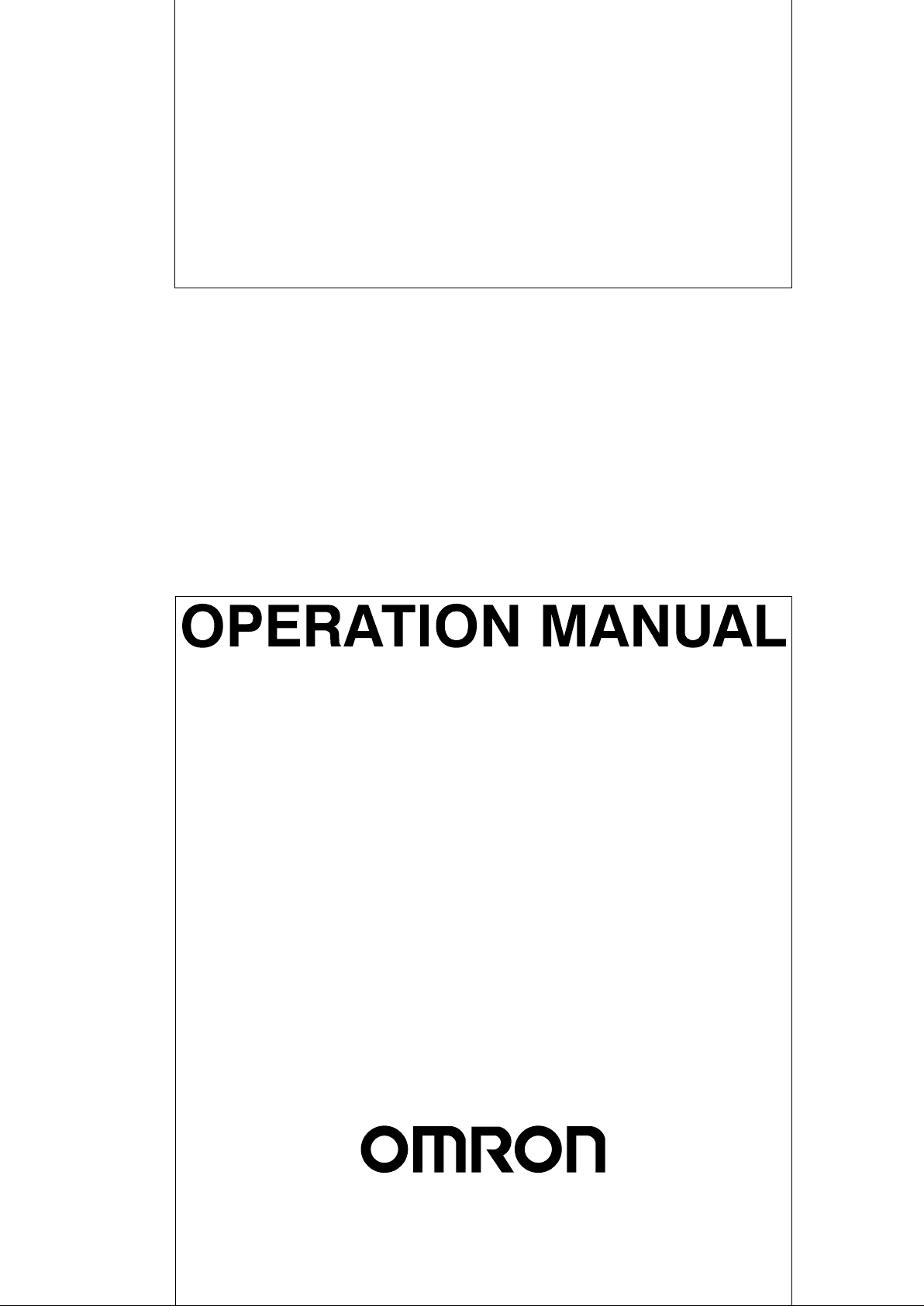
V700-H01 and V700-H02
(RFID) R/W Antennas
V700-CD1D-V3
V700-CD2D-V3
V700-CD1D-V3
V700-CD2D-V3
The V700-CD1D-V3/V700-CD2D-V3 incorporates an RS-232C interface, thus
connecting to personal computers and Programmable Controllers (PCs) over
RS-232C to process large amounts of data flexibly with simple commands.
The V700-H01 is a standard antenna that is 250 by 200 mm in size, ideal for
long-distance communications, and ensuring a minimum communications distance of 250 mm. The V700-H02 is a wide-field antenna th at i s 650 by 200 mm in
size. Compared with the V700-H01, the V700-H02 provides rough positioning
and better communications with ID Tags moving at high-speed.
V700-D23P31 and
V700-D23P41 (RFID) Tags
Highly Functional RFID
System
Ease of Use
The V700-D23P31 Data Carrier has a memory capacity of 240 bytes. It is coin–
shaped and measures only 20 mm across. It resists water , chemicals, and other
elements of harsh environments and can hold data for 200 hours at 180°C. The
V700-D23P41 Data Carrier also has a memory capacity of 240 bytes. It is barshaped and only 3.9 mm in diameter and 25 mm long. It mounts easily in drill
holes or other tight locations, simplifying mounting to machines or products. It
holds up under harsh environments and can hold data from –40 to 110°C, is
highly resistant to water and can be stored at a wide range of temperatures.
The RFID System operates in either multiple, simultaneous access mode or
FIFO (first-in, first-out) read/write mode. In multiple, simultaneous access mode,
if there is more than one ID Tag in the communications area, the RFID System
reads and writes data from and to the all ID Tags at one time. In FIFO read/write
mode, the RD-ID System reads and writes data to one ID Tag after another as
they come into the communications area.
The C200H-PRO27-E Programming Console (sold separately) can be connected to the RFID System over the V700-P10 Programming Console Conversion Cable (sold separately). With the Programming Console, the communications condition of the System can be monitored on-line. Furthermore, the error
log of the System and the ambient noise measurement in the communications
area can be read with ease. All these functions make it possible to start up the
System quickly and improve the efficiency of on-site maintenance work on the
System.
2
1-1SectionCharacteristics
Differences between
V700-CD1D-V2 and
V700-CD1D-V3
The V700-CD1D-V3 adds the following features to those of the V700-CD1D-V2.
They are upwardly compatible with the V700-CD1D-V2, so the V700-CD1D-V2
can be replaced by the V700-CD1D-V3 just as it is.
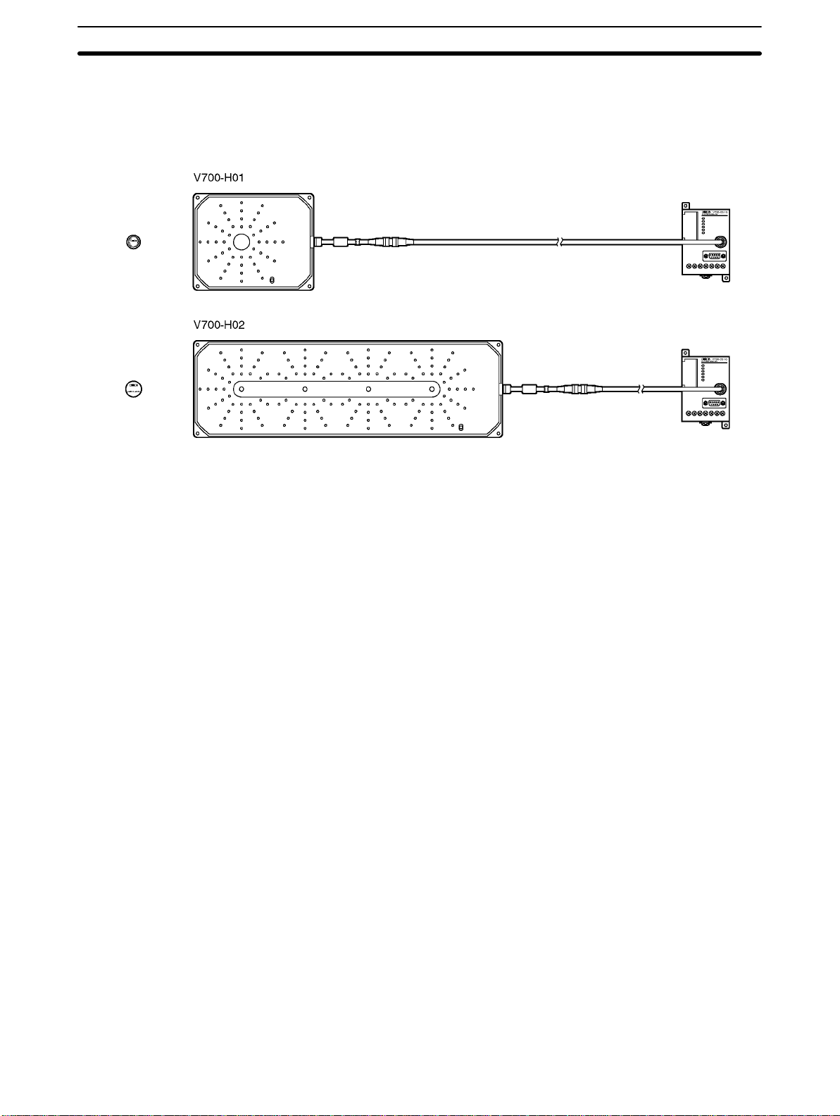
1, 2, 3... 1. Communications Format Settings
BBC can be enabled or disabled in the command and response format between the host and the Controller.
BCC Enabled
Node No.
STX
”jj”
12
Text
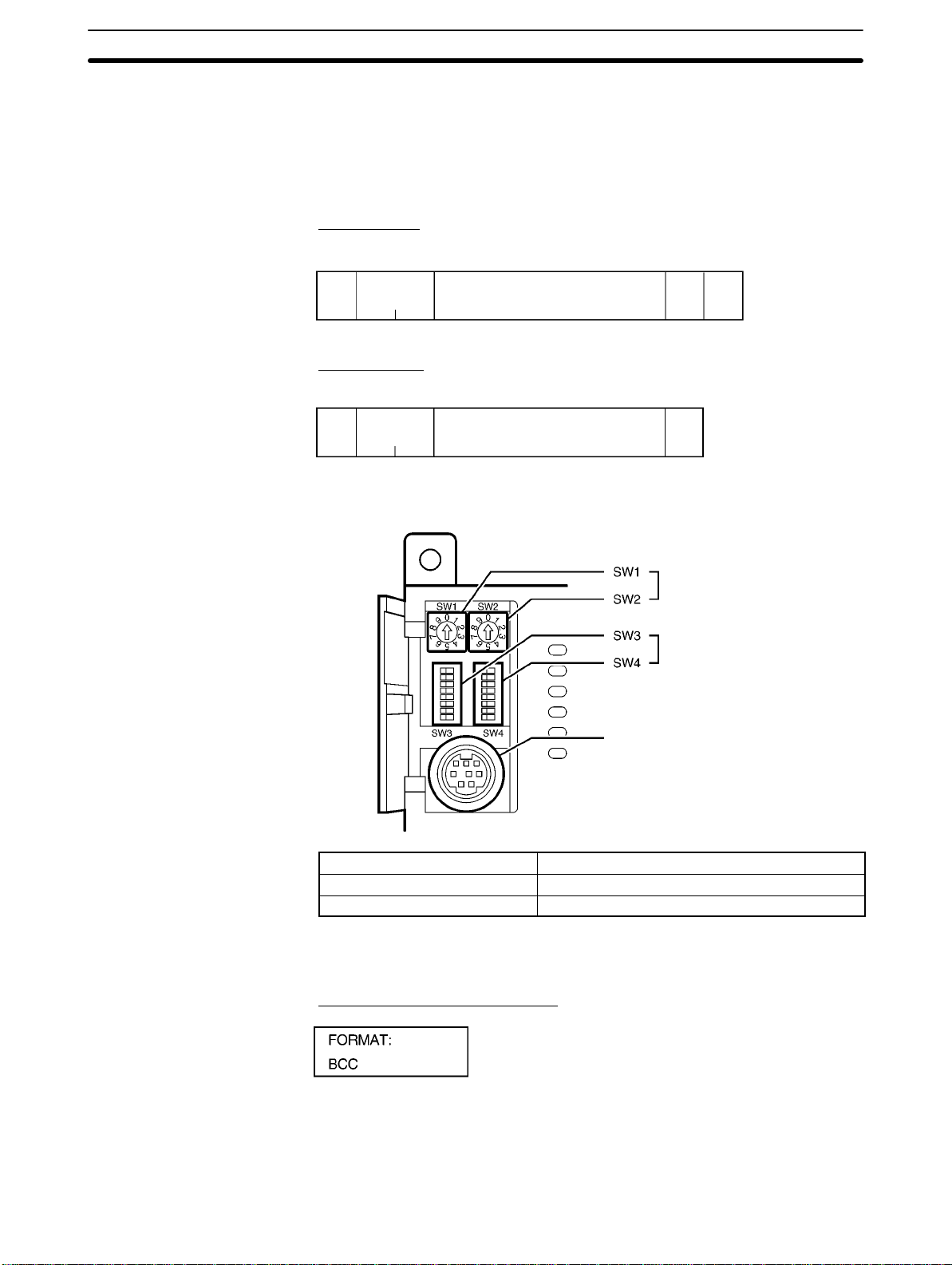
BCC Disabled
Node No.
STX
”jj”
12
Text
This setting is made at pin 1 of DIP switch SW3.
ETX BCC
1
1
ETX
1
Node Number Switches
DIP Switches
Programming Console Port
SW3, pin 1 Setting
ON BCC disabled
OFF BCC enabled (default)
2. Checking the Communications Format Using the Programming Console
The Controller’s communications format settings can be checked in the Programming Console’s settings display.
BCC Enabled (Pin 1 Set to OFF)
3
BCC Disabled (Pin 1 Set to ON)
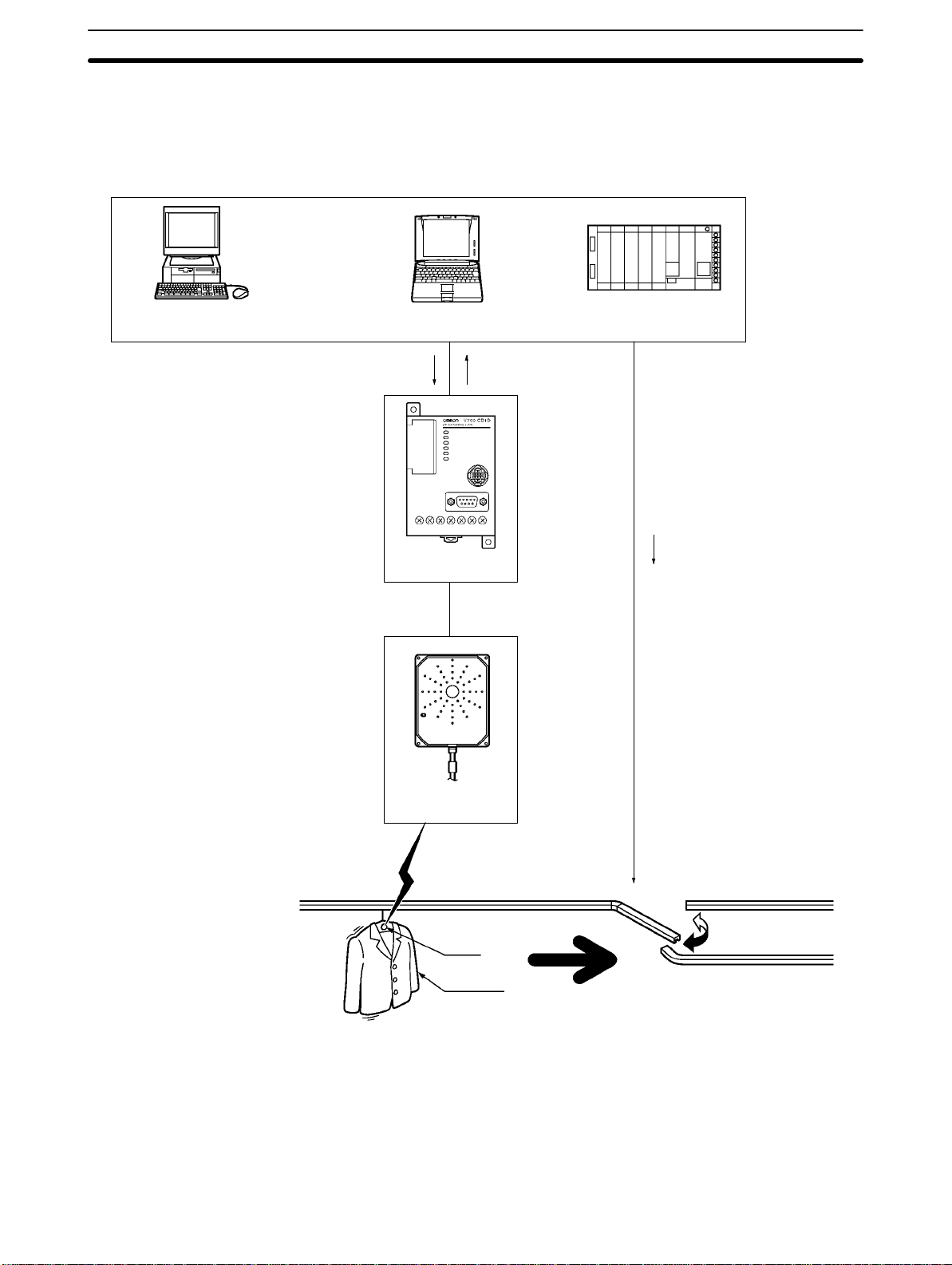
1-2 System Configuration
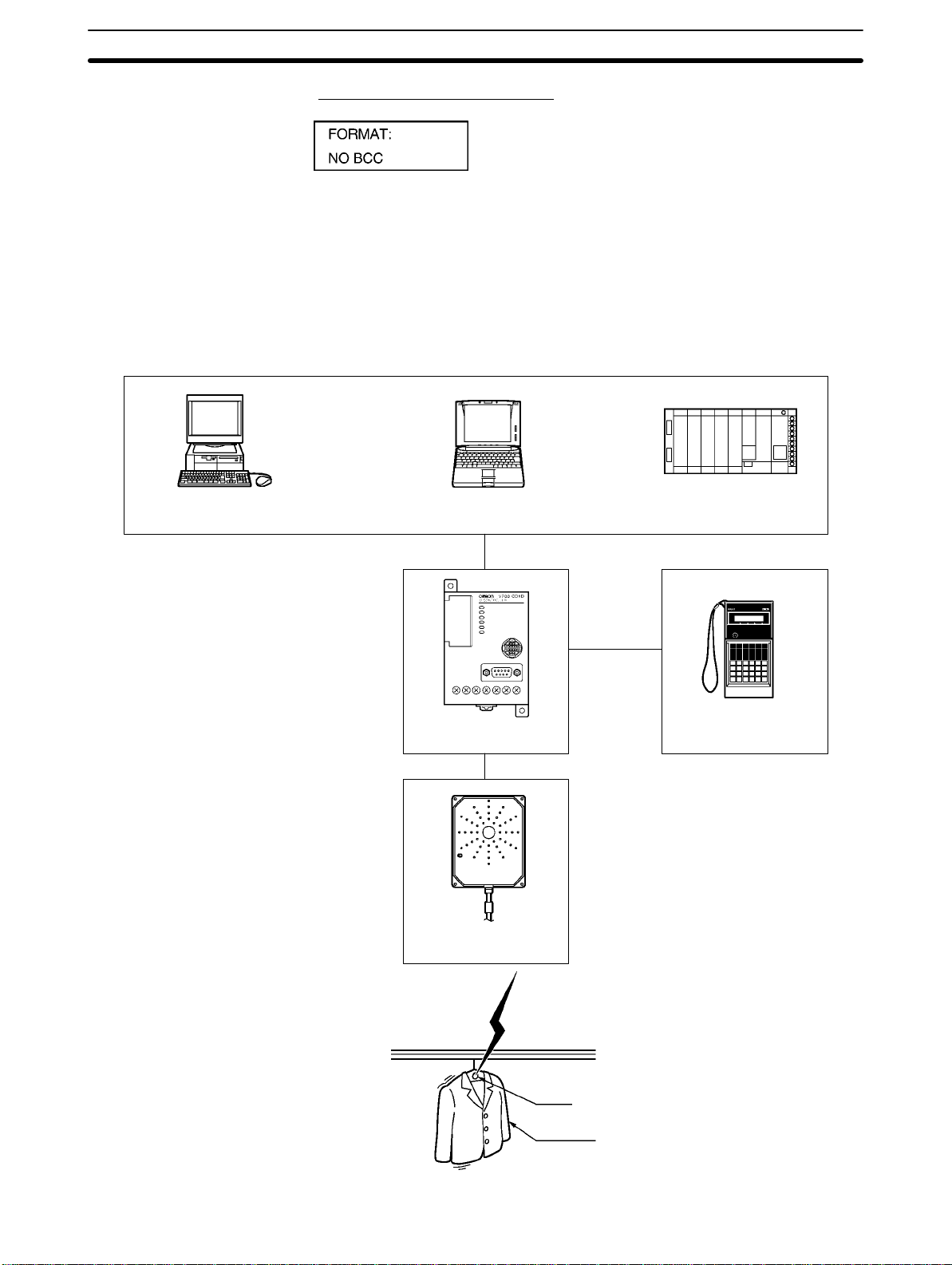
1-2-1 Example of V700-CD1D-V3 System Configuration
The V700-CD1D-V3 has a built-in serial interface conforming to RS-232C, thus
making it possible to communicate with personal computers and PCs.
The host issues all commands to process all communications with the Tag ID.
Host
1-2SectionSystem Configuration
Desktop Personal Computer Notebook Personal Computer PC
RS-232C
V700-P10
V700-CD1D-V3 Programming Console
V700-AF
V700-H01
j
ID Tag
Clothes
4
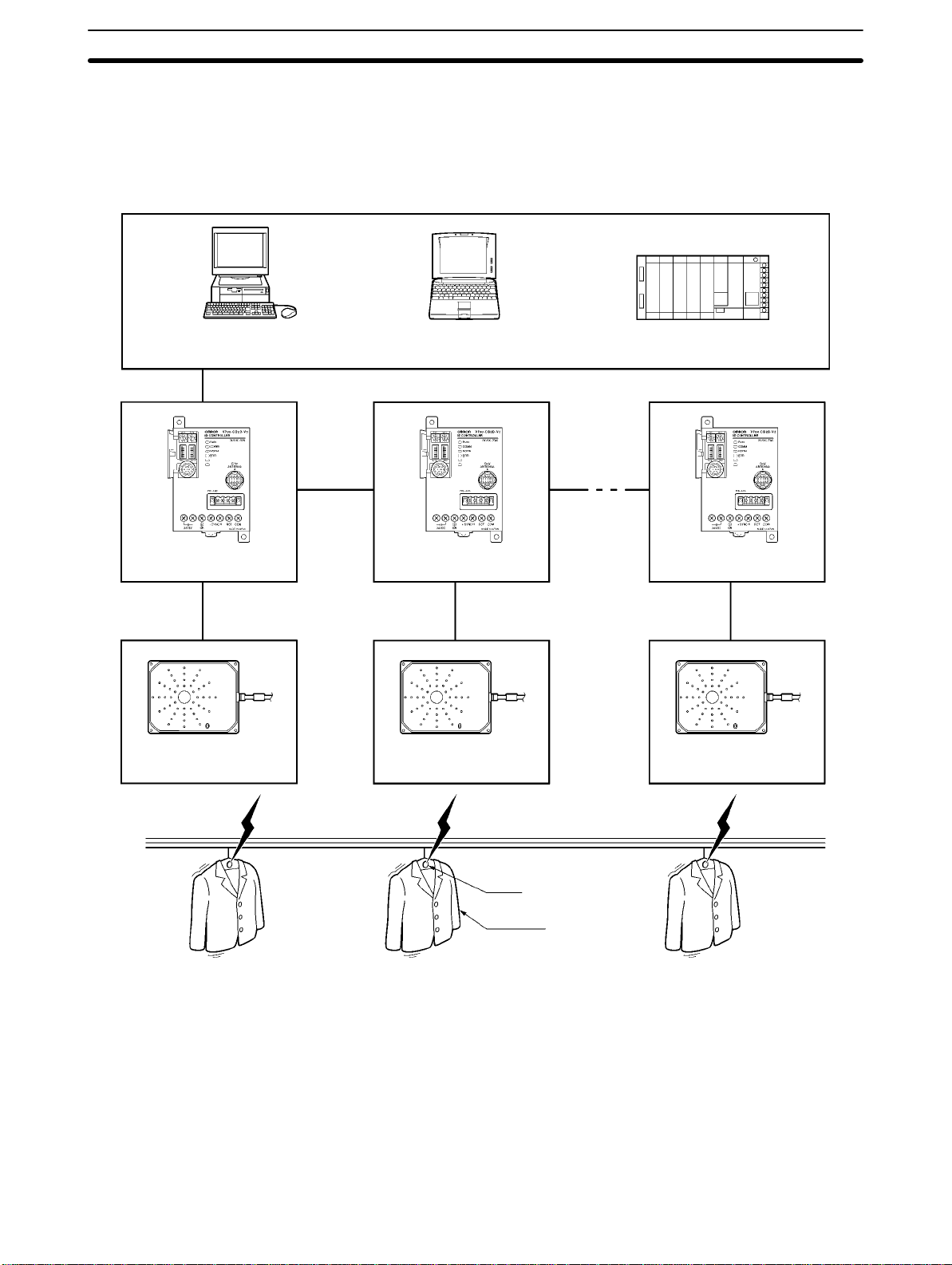
1-2-2 Example of V700-CD2D-V3 System Configuration
The V700-CD2D-V3 has a built-in RS-485 interface, so a maximum of 31
RS-485 Controllers can be connected to a single host device such as a personal
computer or PC. The maximum total length of the RS-485 cable is 300 meters.
Host
Desktop Personal Computer Notebook Personal Computer PC
RS-485
1-2SectionSystem Configuration
RS-485
V700-CD2D-V3 V700-CD2D-V3 V700-CD2D-V3
V700-A4j V700-A4j V700-A4j
V700-H01 V700-H01 V700-H01
ID Tag
Clothes
RS-485
5
1-3 Outline of Operation
The following provides an overview of the operation of the RFID System using
an example that sorts items of clothing each attached with an ID Tag.
Host
Desktop Personal Computer Notebook Personal Computer PC
READ Command Response
1-3SectionOutline of Operation
V700-CD1D-V3
V700-H01
Communication
ID Tag
Clothes
I/O control
Processing (Sorting)
1, 2, 3... 1. When the host sends the command to the Controller, the Antenna stands by
for the arrival of the ID Tag.
2. When the ID Tag arrives in the communications area, the Controller receives data in the memory area of an ID Tag specified by the READ command and sends the data as a response to the host.
3. The host sorts the clothes on the basis of the data.
6

SECTION 2
Specifications and Performance
This section provides the specifications and performance characteristics of each component of the V700 System.
2-1 Controller 8. . . . . . . . . . . . . . . . . . . . . . . . . . . . . . . . . . . . . . . . . . . . . . . . . . . . . . . . . . . . . . .
2-1-1 Nomenclature 8. . . . . . . . . . . . . . . . . . . . . . . . . . . . . . . . . . . . . . . . . . . . . . . . . . . . .
2-1-2 Specifications 10. . . . . . . . . . . . . . . . . . . . . . . . . . . . . . . . . . . . . . . . . . . . . . . . . . . . .
2-1-3 Dimensions 13. . . . . . . . . . . . . . . . . . . . . . . . . . . . . . . . . . . . . . . . . . . . . . . . . . . . . .
2-2 Antenna 13. . . . . . . . . . . . . . . . . . . . . . . . . . . . . . . . . . . . . . . . . . . . . . . . . . . . . . . . . . . . . . . .
2-2-1 Specifications 13. . . . . . . . . . . . . . . . . . . . . . . . . . . . . . . . . . . . . . . . . . . . . . . . . . . . .
2-2-2 Dimensions 14. . . . . . . . . . . . . . . . . . . . . . . . . . . . . . . . . . . . . . . . . . . . . . . . . . . . . .
2-3 ID Tag 16. . . . . . . . . . . . . . . . . . . . . . . . . . . . . . . . . . . . . . . . . . . . . . . . . . . . . . . . . . . . . . . . . .
2-3-1 Specifications 16. . . . . . . . . . . . . . . . . . . . . . . . . . . . . . . . . . . . . . . . . . . . . . . . . . . . .
2-3-2 Dimensions 17. . . . . . . . . . . . . . . . . . . . . . . . . . . . . . . . . . . . . . . . . . . . . . . . . . . . . .
2-3-3 Memory Map 18. . . . . . . . . . . . . . . . . . . . . . . . . . . . . . . . . . . . . . . . . . . . . . . . . . . . .
2-3-4 V700-A80 Attachment (For V700-DjjP31) 19. . . . . . . . . . . . . . . . . . . . . . . . . . .
2-4 Cable 19. . . . . . . . . . . . . . . . . . . . . . . . . . . . . . . . . . . . . . . . . . . . . . . . . . . . . . . . . . . . . . . . . . .
2-4-1 Specifications 19. . . . . . . . . . . . . . . . . . . . . . . . . . . . . . . . . . . . . . . . . . . . . . . . . . . . .
2-4-2 Dimensions 20. . . . . . . . . . . . . . . . . . . . . . . . . . . . . . . . . . . . . . . . . . . . . . . . . . . . . .
2-5 External Communications Specifications 20. . . . . . . . . . . . . . . . . . . . . . . . . . . . . . . . . . . . . .
2-6 V700 Communications Specifications 20. . . . . . . . . . . . . . . . . . . . . . . . . . . . . . . . . . . . . . . . .
7
2-1 Controller
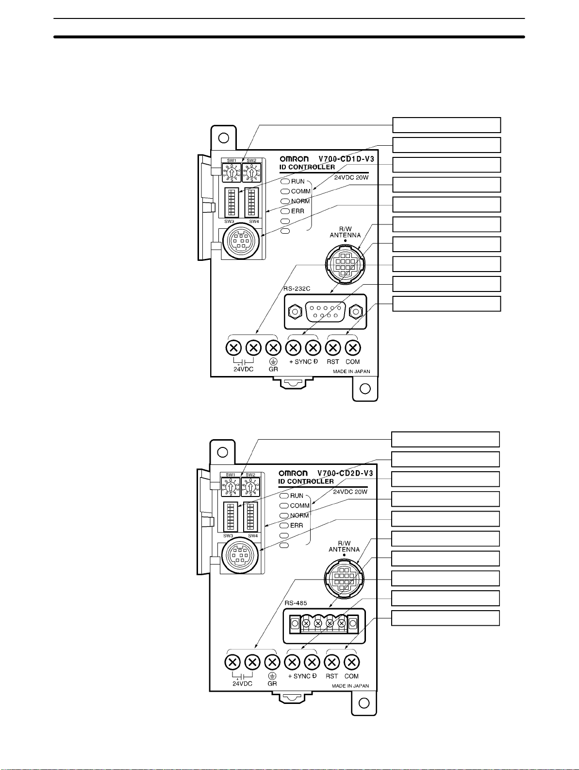
2-1-1 Nomenclature
V700-CD1D-V3
2-1SectionController
1 Node Number Switches
2 DIP Switches
3 Indicators
4 Cover
5 Programming Console Port
6 Antenna Port
7 RS-232C Port
8 Power Supply and Ground Terminals
9 SYNC Terminals
10 RESET terminals
V700-CD2D-V3
1 Node Number Switches
2 DIP Switches
3 Indicators
4 Cover
5 Programming Console Port
6 Antenna Port
7 RS-232C Port
8 Power Supply and Ground Terminals
9 SYNC Terminals
10 RESET terminals
8

Refer to all sections following this section for the functions of the Controller in
gp
l
l
g
detail. Refer to Section 4 Setting, Mounting and Connection Methods for the settings and connections of the Controller.
No. Name Function Description
1 Node number
switch
2 DIP switch Used for mode
3
Indicator The following indicators are available.
RUN Green RUN indicator Turns ON when the Controller is in normal operation.
COMM Green Communications
NORM Green Normal indicator Turns ON and OFF once when the communications finish with no
ERR Red Error indicator Turned ON and OFF once if a communications error results.
4 Cover Protection of SW1
5 Programming
Console port
6 Antenna Port Connecting to the
7 RS-232C port Connecting to host
8
Power supply
terminals
24 VDC+
24 VDC–
GR Connecting to ground Ground this terminal at a resistance of less than 100Ω.
9
SYNC terminals Used for synchronization
SYNC+
SYNC–
10
RESET terminals Connecting to RESET signal
RST RESET signal
COM COMMON signal
Used for node
number settings
settings
indicator
through SW4 and the
Programming
Console port
Connecting to the
Programming
Console
Antenna
devices
Connecting to power supply
Connecting to power
supply
Connecting to
synchronous signa
The node number is used to identify each Controller when a single
host computer is connected to a maximum of 32 Controllers.
Various settings are possible (e.g., communications
synchronization, energy-saving, communications distance,
terminating resistance, baud rate, data length, parity, stop bit
length, communications mode, and time-out settings).
Turns ON when the Controller is in communications with the ID
Tag.
error.
Turned ON if a system error results.
Open the cover only when necessary.
OMRON’s C200H-PRO27-E Programming Console (sold
separately) can be connected through the V700-P10 Programming
Console Conversion Cable (sold separately). The V700-P10 is
provided with a dedicated key sheet used for the operation of the
Programming Console.
A single Antenna can be connected through the V700-A4j
Antenna Cable (sold separately).
The following Antennas are available.
• V700-H01 (standard antenna, 250 x 200 mm in size)
• V700-H02 (wide-field antenna, 650 x 200 mm in size)
Personal computers and PCs can be connected over RS-232C.
Connect 24 VDC.
Connect 0 V.
These terminals are used together for synchronizing more than
one Controller in order to reduce the distance of mutua
interference of each corresponding Antenna.
These terminals are used together in order to use external RESET
input.
2-1SectionController
9
2-1-2 Specifications
General Specifications
Item Specification
Supply voltage 24 VDC
Power consumption 20 W max. including the power consumption of the Antenna (1.1 A at 12 V) and the
Programming Console (150 mA at 5 V)
Insulation resistance 20 MΩ min. (at 100 VDC) between the ground and both power supply terminals,
both power supply terminals and both I/O terminals, both power supply terminals
and casing, both I/O terminals and ground, both I/O terminals and casing, and
ground terminal and casing.
Dielectric strength 500 VAC (50/60 Hz) for 1 minute in any of the above combinations.
Vibration resistance Destruction: 10 to 150 Hz, 0.3-mm double amplitude at 20 m/s2 in X, Y, and Z
Shock resistance Destruction: 200 m/s2 in X. Y. and Z directions 3 times each
Ambient operating temperature –10°C to 55°C (with no icing)
Ambient operating humidity 35% to 85% (with no condensation)
Ambient storage temperature –25°C to 65°C (with no icing)
Ground Ground at a resistance of less than 100 Ω.
Construction Panel-mounting
Material PC/ASA resin
Weight Approx. 290 g
Number of connectable Antennas 1
Applicable standards EN50081-2, EN50082-2
+10%
/
–15%
directions four times each for 8 minutes
2-1SectionController
Performance Specifications
Item Specification
Self-diagnostics CPU, host communications, Controller communications, and synchronous
communications errors are checked.
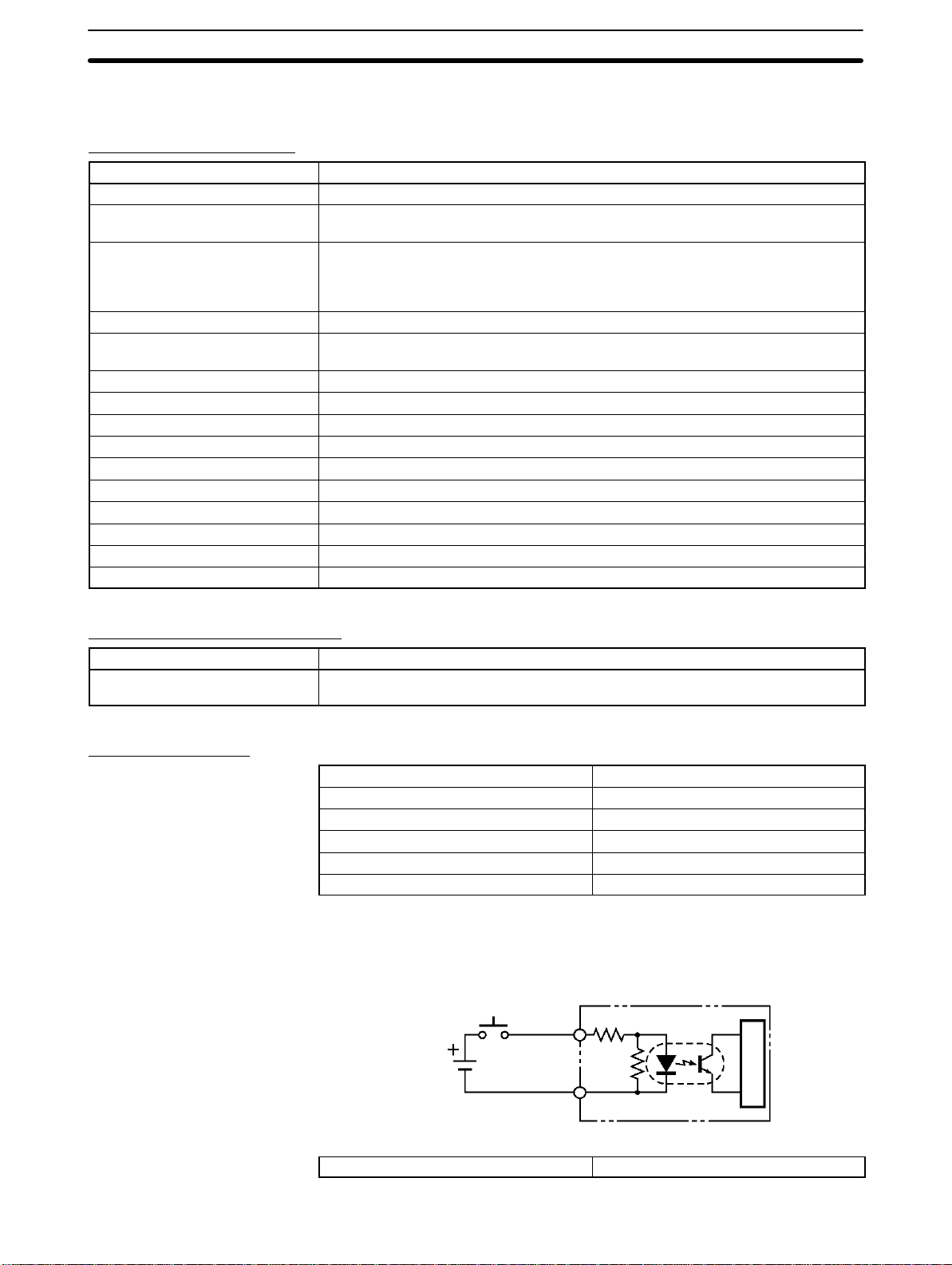
I/O Specifications
External RESET Input
Input voltage 24 VDC
Input impedance 2.2 kΩ
Input current 10 mA TYP (24 VDC)
ON voltage 19 V min.
OFF voltage 5 V max.
Input response time 70 ms max.
Circuit Configuration
Controller
2.2 kΩ
RESET
terminal
24 VDC
COM (0 V)
+10%
/
(including ripples)
–15%
Internal circuit
SYNC
10
I/O interface Conforms to RS-485
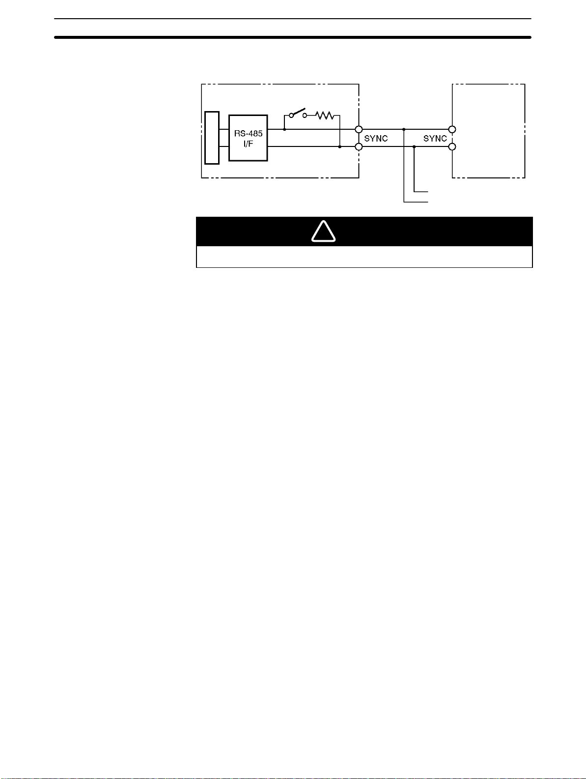
Circuit Configuration
2-1SectionController
Controller
Terminating resistance
Positive
terminal
Internal circuit
!
The positive SYNC or negative SYNC terminal is not an RS-485 terminal. Do not
connect anything other than coaxial cables to these terminals.
Negative
terminal
CAUTION
Positive
terminal
Negative
terminal
Another Controller
Another Controller
11
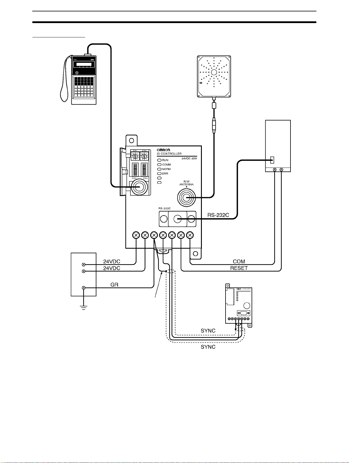
Wiring Example
C200H-PRO27-E
Programming Console
V700-P10
Programming
Console
Conversion Cable
V700-CD1D-V3
Controller
V700-CD1D-V3
2-1SectionController
V700-Hjj Antenna
Host PC
V700-A4j
Antenna Cable
24-VDC power supply
+
–
Another Controller
Shielded wire
–
+
12

2-1-3 Dimensions
2-2SectionAntenna
V700-CD1D-V3
Two, 4.5 dia.
Two, M4
Casing material: PC/ASA resin
2-2 Antenna
2-2-1 Specifications
Item
V700-H01 V700-H02
Oscillation frequency 125 kHz
Ambient operating temperature –20°C to 55°C (with no icing)
Ambient storage temperature –35°C to 65°C (with no icing)
Ambient operating humidity 35% to 85% (with no condensation)
Insulation resistance 50 MΩ min. (500 VDC) between the cable terminal and casing.
Dielectric strength 1,000 VAC min. (50/60 Hz) between the cable terminal and casing for 1 minute
Degree of protection IP40 (except connector)
Vibration resistance Destruction: 10 to 150 Hz, 1.5 mm double amplitude at 100 m/s2 in X, Y, and Z
directions twice each for 8 minutes
Shock resistance Destruction: 200 m/s2 three times each in X, Y, and Z directions
Communications error
detection
Cable length 0.1 m (use an extension cable to connect to the Controller up to 50.1 m)
LED indication Power supply: Green
Weight Approx. 800 g Approx. 1,800 g
Electric field strength 15 µV/m maximum at a distance of λ/2π.
Bilateral use of CRC (Cyclic Redundancy Check) 16 bits
Communications: Orange
Model
13

2-2-2 Dimensions
V700-H01
2-2SectionAntenna
CAUTION
!
The Connector is not water-resistant. Make sure that the connector is free of water.
185±0.2
235±0.2
Four, 5 dia.
mounting holes.
20 max.
16 max.
Casing material PC/ASA resin
Rear panel material Phenol resin
Cable PVC
14

V700-H02
2-2SectionAntenna
185±0.2
20 max.
635±0.2
Four, 5 dia.
mounting holes.
16 max.
Casing material PC/ASA resin
Rear panel material Phenol resin
Cable PVC
15

2-3 ID Tag
e peaue
2-3-1 Specifications
2-3SectionID Tag
Item
V700-D23P31 V700-D23P41
Memory capacity User area: 240 bytes
Type of memory EEPROM (non-volatile memory)
Data backup time 10 years
Data writing times 100,000 times per address
Communications error
detection
Ambient operating
temperature
Ambient storage temperature –40°C to 110°C (with no icing) –40°C to 110°C (with no icing)
Ambient operating humidity No limits 35% to 95% (with no condensation)
Heat resistance Thermal cycle:
Degree of protection IP68 (IEC60529 standards) IP67 (IEC60529 standards)
Vibration resistance Destruction: 10 to 2,000 Hz, 1.5-mm double amplitude at 150 m/s2 in X, Y, and Z
Shock resistance Destruction: 500 m/s2 in ±X, ±Y, and ±Z directions 3 times each, 18 times total
Material PPS resin PBT resin with PET resin fill
Weight Approx. 2 g Approx. 1 g
Bilateral use of CRC (Cyclic Redundancy Check) 16 bits
Communicating: –20°C to 70°C (with no
icing)
Not communicating: –40°C to 110°C (with no icing)
20°C/180°C for 30 minutes each 200 times
Constant high temperature:
180°C for 200 hours
directions ten times each for 15 minutes
Model
Communicating: –25°C to 70°C (with no
icing)
The above ambient storage temperature
range
Note The V700-D23P31 can be stored at a temperature of 180°C for 200 hours. The
V700-D23P31 can be, however, in normal operation (i.e., the V700-D23P31 located in the communications area) at a maximum of 70°C. This means the temperature of the ID Tag itself in operation must not exceed 70°C. Before using the
ID Tag, conduct some tests and check that the temperature of the ID Tag itself in
operation is 7 0 °C maximum. If the temperature of the ID Tag is 180°C, it normally
takes a period of one minute for the temperature to drop to 70°C for an ambient
temperature of 2 5 °C. Take this into consideration when cooling down the ID Tag.
16

2-3-2 Dimensions
V700-D23P31
V700-D23P41
2-3SectionID Tag
1.1 2.7±0.1
16 dia. ±0.1
20 dia. ±0.1
3.9±0.1 dia.
R1
JAPAN 0249
V700-D23P41
R0.25
17

2-3-3 Memory Map
2-3SectionID Tag
The V700-D23P31 has a memory area of 240 bytes, and the V700-D13P21 has
a memory area of 1 12 bytes. One-byte data can be written to a single address.
An eight-byte block of memory area is treated as one page.
Address Data
Page 01
Page 02
One byte
Eight
bytes
Page 14
Page 30
112 bytes
240 bytes
70h
E8h
E9h
EAh
EBh
ECh
EDh
18
EEh
EFh

2-3-4 V700-A80 Attachment (For V700-DjjP31)
This is a special Attachment for fastening a coin-shaped ID Tag to a workpiece. It
can be used with V700-DjjP31 models.
2-4SectionCable
External Dimensions
Two, 6 dia.
Two, 3.5 dia. (Mounting hole)
Mounting Procedure
Mounting Hole Dimensions
40
24
18
22
31±0.2
3.5
1
22
8
5
31±0.2
Two, M3
1, 2, 3... 1. Insert the coin-shaped ID Tag into the Attachment. The coin-shaped ID Tag
has no directionality, so it can be faced in any direction.
2. Use M3 screws to fasten the Attachment, and tighten the screws to a torque
of 0.3 to 0.5 NSm.
General Specifications
Influence of Background
Metal
Conforming to ID Tag specifications.
When this Attachment is used, the distance between the ID Tag and the work-
piece is approximately 8 mm. If the workpiece is made of metal, refer to 8-8 Influ-
ence of Background Metal on ID Tag.
Note Do not repeatedly insert and remove the ID Tag from the Attachment. Doing so
can loosen the fit of the ID Tag and break the Attachment clasps. In case it should
become necessary to remove an ID Tag once it has been inserted, do so by inserting a flat-blade screwdriver into the space between the Attachment and the
ID Tag at the bottom of the Attachment. Do not use bare hands to remove the ID
Tag, or the ID Tag may be damaged.
2-4 Cable
2-4-1 Specifications
Item
V700-P10
Number of conductors 8 10
Insulation resistance 50 MΩ min. (at 250 VDC) between
conductor and shield
Dielectric strength 250 VAC 1 min 500 VAC 1 min
Maximum operating temperature 70°C 80°C
Remarks Connectors are not water resistant. Connectors are not water resistant.
Model
V700-A4j
5 MΩ min. (at 500 VDC) between
conductor and shield
19

2-4-2 Dimensions
2-6SectionV700 Communications Specifications
V700-P10
28.95
Connector (Programming Console side) Connector (Controller side)
12
Model V700-P10
Length Approx. 2 m
Weight Approx. 110 g
2,000±100
12 dia.
4.8 dia.
V700-A4j
Item
V700-A40 V700-A41 V700-A42 V700-A43 V700-A44 V700-A45
Length Approx. 2 m Approx. 3 m Approx. 5 m Approx. 10 m Approx. 20 m Approx. 30 m
Weight Approx. 150 g Approx. 220 g Approx. 360 g Approx. 700 g Approx. 1,350 g Approx. 2,000 g
L1 2,000 3,000 5,000 10,000 20,000 30,000
Model
51 L1±100 49
15 dia.
6 dia.
Connection label
2-5 External Communications Specifications
Item Specification
Communications method Electromagnetic induction (with no battery)
Modulation method ASK mode
Transmission frequency 125 kHz
Reception frequency 125 kHz
15.5 dia.
Connector (Controller side)Connector (Antenna side)
2-6 V700 Communications Specifications
The Controller can be connected to personal computers and PCs over
RS-232C.
20

V700-CD1D-V3
Item Specifications
Conforming standards RS-232C
Communications method EIA/TIA-232-E, 1-to-N half duplex
Baud rate 4,800 bps, 9,600 bps, 19,200 bps, 38,400 bps
Sync Start-stop synchronization with 1 stop bit or 2 stop bits
Transmission code ASCII7 or JIS8
Max. connectable number of Controllers 32
Error control (see note) Vertical parity (even, odd, or none)
Horizontal parity as BCC
Cable length 15 m max.
Suitable connector D-sub 9-pin male connector
OMRON XM2A-0901 Plug and XM2S-0911 Hood provided with the
Controller
Recommended cable Hitachi Cable CO-MA-VV-SB 5Px28AWG
V700-CD2D-V3
Item Specifications
Conforming standards RS-485
Communications method EIA standards, RS-485, 1:N, 2-wire, bi-directional, half-duplex
communications
Baud rate 4,800 bps, 9,600 bps, 19,200 bps, 38,400 bps
Sync Start-stop synchronization with 1 stop bit or 2 stop bits
Transmission code ASCII7 or JIS8
Max. connectable number of Controllers 31
Error control (see note) Vertical parity (even, odd, or none)
Horizontal parity as BCC
Cable length 300 m max.
Suitable connector BLZ4CD2D (made by Nihon Weidmiiller Co., Ltd.); one set provided with
Controller
Recommended cable MVVS4CX0.5Sq (made by Tachii Electric Wire Co., Ltd.)
2-6SectionV700 Communications Specifications
Precautions
Note The DIP switches of the Controller are available to vertical parity settings. Refer
to Section 4 Setting, Mounting, and Connection Methods for details.
Be sure to set the baud rate to 9,600 bps or higher when commands are used in
repeat mode. Otherwise, all moving ID Tags may not be processed. Refer to
Section 5 Communications Functions for the commands used in repeat mode.
Note Use shielded twisted-pair cable equivalent to AWG20 if the recommended cable
(MVVS4CX0.5Sq) for the V700-CD2D-V3 is not used.
21


This section provides the modes and functions in detail.
3-1 Single, FIFO Read/Write, and Multiple, Simultaneous Access Functions 24. . . . . . . . . . . . .
3-2 Write Protect Function 25. . . . . . . . . . . . . . . . . . . . . . . . . . . . . . . . . . . . . . . . . . . . . . . . . . . . .
3-3 Memory Check Function 25. . . . . . . . . . . . . . . . . . . . . . . . . . . . . . . . . . . . . . . . . . . . . . . . . . .
3-4 Mutual Interference Preventive Function (Synchronous Function) 26. . . . . . . . . . . . . . . . . . .
3-5 Energy-saving Mode 28. . . . . . . . . . . . . . . . . . . . . . . . . . . . . . . . . . . . . . . . . . . . . . . . . . . . . .
3-6 Long-distance Mode and Stable Communications Mode
(Communications Distance Setting) 28. . . . . . . . . . . . . . . . . . . . . . . . . . . . . . . . . . . . . . . . . .
3-7 Noise Environment Measurement Function 29. . . . . . . . . . . . . . . . . . . . . . . . . . . . . . . . . . . . .
3-8 Error Logging Function 29. . . . . . . . . . . . . . . . . . . . . . . . . . . . . . . . . . . . . . . . . . . . . . . . . . . .
SECTION 3
Functions
23

3-1 Single, FIFO Read/Write, and Multiple, Simultaneous
Access Functions
Three communication modes are available depending on the number or state of
Tags in the communication area. Commands can be used for selecting one of
them. Refer to Section 5 Communications Functions for details.
3-1SectionSingle, FIFO Read/Write, and Multiple, Simultaneous Access Functions
Single Mode
FIFO Read/Write Mode
In this mode, only a single ID T ag can be in the communications area, otherwise
a communications error will result.
In the FIFO (first-in, first-out) read/write mode, the RFID System reads and
writes data to and from each ID Tag coming into the communications area one
after another. S ince every ID Tag finished with communications is set to access
prohibit, communications will be possible if only one ID Tag newly arrives in the
communication area of th e A n t e n n a where more than one ID Tag exists. An error, however, results if two or more ID Tags arrive in the communications area
simultaneously. When the access-prohibited Tag moves out of the communications area, communications will become possible again.
Multiple, Simultaneous
Access Mode
24
In this mode, communications with all ID Tags in the communications area can
be made on receipt of the command.

Note In FIFO read/write mode, make sure that multiple ID Tags do not arrive in the
communications area together , otherwise a communications error will result and
further communications will not be possible until there is only a single ID Tag in
the communications area.
3-2 Write Protect Function
The write protect function is a protective function that is provided to prevent permanent data, such as product information and pallet numbers saved to data carriers from being lost through being accidentally overwritten.
Any areas can be write-protected in page units by setting the protection information in the ID Tag. If a WRITE command is executed for a page that has been set
for write protection, a protect error is generated. The data protection area is comprised of one bit per page, for a total of 30 bits. To execute write protection, use
the WRITE PROTECT (WP) command to set the bit for the relevant page. In the
same way, release the write protection by clearing the bit.
Protection Information
b7 b6
b1 b0
b7 b6
b1 b0
Protection information
b7 b6
b1 b0
b7 b6
b3 b2
3-3SectionMemory Check Function
b1 b0
Page 15
Page 29
Page 30
Page 23
Page 24
Page 21
Page 22
Page 16
3-3 Memory Check Function
By adding check codes to data in ID T ags, it is possible to detect errors i n the data
contents resulting from accidental causes or deterioration as the EEPROM
reaches the end of its service life. For the check code, a CRC code calculated by
the generating polynomial X
A memory check is executed by using the MEMORY CHECK (MC) command to
write the check code, and the MEMORY CALCULATE (MK) command to verify
the check code. The calculation area is the portion of the check block specified
by the first address and the number of bytes excluding the last two bytes. The
check code area is the last two-byte portion.
When a command to write a check code is sent, the CRC code of the data in the
calculation area is calculated and written to the check code area. When a command to verify the data is sent, the CRC code of the data in the calculation area is
calculated and compared with the data in the check code area. If they coincide,
Page 13
Page 14
Page 6
Page 7
Page 8
16
+ X12 + X5 + 1 is used.
Page 5
Page 2
Page 1
Fixed at 0
Fixed at 0
25

3-4SectionMutual Interference Preventive Function (Synchronous Function)
response code 75, which indicates normal data transmission, is returned. If they
do not coincide, response code 76 is returned as a warning.
Address
0 0
0 1
First address
of the area
Check code calculation area
(Number of check block bytes: 2)
Method of Operation
CRC (left digit)
CRC (right digit)
Check code area (two bytes)
After data is written, use the MEMORY CHECK (MC) command to calculate and
write the check code. Then, before reading the data, use the MEMORY CALCULATE (MK) command to verify the check code. This enables damage to inaccessible data in the ID Tag to be detected in advance.
Write stage
Read stage
Write data
Calculate check code
Verify check code
Read data
3-4 Mutual Interference Preventive Function (Synchronous
Function)
This function can reduce the mutual interference distance of each Antenna.
If two or more Antennas are close to one another, they will not operate properly
due to mutual interference. It is possible to reduce the mutual interference distance of each Antenna by connecting the Controllers together over synchronous
cables through the SYNC terminal as shown below. In this example, one of the
Controller connected in series is set as the Master and the others are set as
Slaves. Be sure to set the terminating resistance of the Controller at each end to
ON and that of other Controllers to OFF. A maximum of 32 Controllers including
the Master and 31 Slaves can be connected within a total cable distance of
300 m maximum. Refer to page 35, DIP Switch Settings, page 44, SYNC signal
26

Wiring, and 8-6 Mutual Interference of Antenna for the settings, cable connec-
tions, and mutual interference distance in detail.
Total distance 300 m max.
Master Slave 1 Slave 2 Slave 31
Switch settings
Slave
Terminating
resistance set to
OFF
Antenna
ID Tag
Switch settings
Master
Terminating
resistance set to ON
Mutual
interference
1 m min.
Switch settings
Slave
Terminating
resistance set to
OFF
Switch settings
Slave
Terminating
resistance set to ON
3-4SectionMutual Interference Preventive Function (Synchronous Function)
Note 1. Be sure to set only one of the Controllers as the Master and other Controllers
as Slaves in synchronous operation, otherwise the RFID System will not operate.
2. Be sure to set the terminating resistance of the Controller at each end to ON
and that of any other Controller to OFF, otherwise stable operation of the
RFID System will not be possible.
There are two types of synchronous functions to reduce the mutual interference
distance of each Antenna. These functions are called R/W (read/write) synchronous and RO (read-only) synchronous functions. Both READ and WRITE commands are available to the R/W synchronous function. Only the READ command is available to the RO synchronous function. The RO synchronous function requires a shorter communications time than the R/W synchronous function. Refer to 8-4 Communications Time and page 35, DIP Switch Settings for
details.
Item
RW RO No synchronous
Synchronous cable To be connected Not required
Mutual interference
Short Long
distance between
Antennas
WRITE command Possible to use Not possible to use Possible to use
Communications
Long Slightly long Short
time
Synchronous function
function
Precautions
Make sure that all Controllers connected are in the same synchronous type (i.e.,
in R/W synchronous operation, OR synchronous operation, or not in synchronous operation), otherwise the communications of all Controllers may be affected.
27

3-5 Energy-saving Mode
The RFID System can be set to energy-saving mode.
In case commands can be issued only during communications, the Antenna
power can be shut down to reduce the total power consumption of the RFID System. In energy-saving mode, the power consumption of the RFID System is
approximately 30% of that in normal operation.
If the Controller is set to energy-saving mode, the Antenna will have output only
at the time of communications. This mode is available while a communications
command is issued to select the single trigger, single auto, or multi-trigger option.
3-6SectionLong-distance Mode and Stable Communications Mode
Item
Normal mode Energy-saving mode
Power consumption High Low
Antenna output during
communications
Antenna output during
standby periods
Command A Available
Command B Available Not available
Other command Available
Note 1. Command A
Single trigger, single auto, and multi-trigger
Command B
Single repeat, FIFO trigger , FIFO auto, FIFO repeat, multi-trigger, and multirepeat
2. Refer to page 35 DIP Switch Settings and 5-10 Communications Command
for details.
Note Do not set the Controller to energy-saving mode if the single repeat, FIFO trig-
ger, FIFO auto, FIFO repeat, multi-trigger, or multi-repeat option is selected,
otherwise a command error will result.
ON
ON OFF
Mode
3-6 Long-distance Mode and Stable Communications Mode
(Communications Distance Setting)
Long-distance Mode
Stable Communications
Mode
28
In order to perform long-distance communications, the RFID System automatically selects the amplification factor when the Antenna receives signals from the
ID Tag. If the ID Tag is far, the amplification factor increases automatically in order to receive the weak signal of the ID Tag.
If there is excessive noise (particularly, air-conditioner noise), the automatic
selection of the amplification factor should be suppressed. If this automatic
selection is suppressed, the RFID System cannot communicate with far ID Tags
but the RFID can perform stable communications even under an environment
where noise is prevalent.
The RFID System allows a selection of either long-distance mode (automatic
selection of amplification factor) or stable-communications mode (no change in
amplification factor). Refer to page 35, DIP Switch Settings for details.

3-8SectionError Logging Function
Item
Long-distance mode Stable communications
Antenna’s signal reception
amplification factor
Communications distance Very long distance Long distance
Environmental noise
interference
Note Environmental noise can be easily checked with the Programming Console. Re-
fer to 3-7 Noise Environment Measurement Function. If the noise environment
measurement function is executed after the Controller is in long-distance mode,
the existing value must not exceed 30. Otherwise, it is recommended that the
Controller be used in stable communications mode.
Low or high (automatically
selectable)
Affected easily Not affected easily
3-7 Noise Environment Measurement Function
Noise environment around the location where the Antenna is installed can be
checked using the Programming Console.
Use this function to arrange the best location and best direction of the Antenna or
to determine whether to set the Controller to long-distance mode or stable communications mode. It is recommended that this function be used to check the
noise environment before installing the RFID System.
To use this function, connect the C200H-PRO27-E Programming Console (sold
separately) through the V700-P10 Programming Console Conversion Cable
(sold separately) to the Controller. R efer to 6-6-8 Noise Environment Check for
details.
Mode
mode
Always low
3-8 Error Logging Function
The error log data of the RFID System can be read on-line through the Programming Console.
Two types of error log data can be read, which makes it possible to analyze system errors.
1. Latest Error Log
2. Statistic Error Log
The Controller keeps a record of errors resulted in RUN mode after the Controller is turned ON. The Programming Console can read information on these errors, thus making it possible to find causes of errors. The Controller keeps a record of a maximum of 30 errors. New errors replace the existing record in chronological order beginning with the oldest error record. The records will be completely lost when the Controller is turned OFF or reset or when it receives a RESET command.
The Controller classifies and keeps the number of each type of error. The Controller also calculates MCBF (mean cycle between failures) simultaneously. The
Controller keeps all these data items until the user turns OFF or resets the Controller.
To use this function, connect the C200H-PRO27-E Programming Console (sold
separately) to the Controller through the V700-P10 Programming Console Conversion Cable (sold separately). Refer to 6-6-9 Latest Error Data and 6-6-10 Sta-
tistic Error Data for details.
Note The record of all errors will be lost when the Controller is turned OFF or reset or
when it receives a RESET command. Do not turn OFF or reset the Controller in
order to keep the records.
29


Setting, Mounting, and Connection Methods
This section provides installation information for the V700 System.
4-1 Controller 32. . . . . . . . . . . . . . . . . . . . . . . . . . . . . . . . . . . . . . . . . . . . . . . . . . . . . . . . . . . . . . .
4-1-1 Switch Settings 32. . . . . . . . . . . . . . . . . . . . . . . . . . . . . . . . . . . . . . . . . . . . . . . . . . .
4-1-2 Installation Environment 37. . . . . . . . . . . . . . . . . . . . . . . . . . . . . . . . . . . . . . . . . . . .
4-1-3 Mounting 38. . . . . . . . . . . . . . . . . . . . . . . . . . . . . . . . . . . . . . . . . . . . . . . . . . . . . . . .
4-1-4 Connection and Disconnection of Antenna Connector 39. . . . . . . . . . . . . . . . . . . . .
4-1-5 Wiring 41. . . . . . . . . . . . . . . . . . . . . . . . . . . . . . . . . . . . . . . . . . . . . . . . . . . . . . . . . .
4-1-6 Connection of RS-232C Interface (V700-CD1D-V3) 45. . . . . . . . . . . . . . . . . . . . . .
4-1-7 RS-485 Interface Connection (V700-CD2D-V3) 49. . . . . . . . . . . . . . . . . . . . . . . . .
4-2 Installation of Antenna 52. . . . . . . . . . . . . . . . . . . . . . . . . . . . . . . . . . . . . . . . . . . . . . . . . . . . .
4-2-1 Installation Environment 52. . . . . . . . . . . . . . . . . . . . . . . . . . . . . . . . . . . . . . . . . . . .
4-2-2 Mounting the Antenna 53. . . . . . . . . . . . . . . . . . . . . . . . . . . . . . . . . . . . . . . . . . . . . .
4-3 ID Tag 54. . . . . . . . . . . . . . . . . . . . . . . . . . . . . . . . . . . . . . . . . . . . . . . . . . . . . . . . . . . . . . . . . .
4-3-1 Installation Environment 54. . . . . . . . . . . . . . . . . . . . . . . . . . . . . . . . . . . . . . . . . . . .
4-3-2 Mounting Method 54. . . . . . . . . . . . . . . . . . . . . . . . . . . . . . . . . . . . . . . . . . . . . . . . .
SECTION 4
31

4-1 Controller
4-1-1 Switch Settings
Opening the Cover
4-1SectionController
Open the cover of the Controller to make switch settings.
A screwdriver is provided with the Controller. Open the cover by inserting the
screwdriver into the groove on the left side of the cover.
32
Under the cover , there are two node number switches (SW1 and SW2), two DIP
switches (SW3 and SW4), and a port to connect the Programming Console.
Node Number Switches
DIP Switches
Programming Console Port

Settings
y
y
g
,p
yg
4-1SectionController
Use the provided screwdriver to make switch settings as shown below.
Node Number Settings DIP Switch Settings
Default Set Values
SW3 (left)
SW4 (right)
The following table shows default set values.
Name Default set
value
SW1 Node number (10’s digit) 0
SW2 Node number (1’s digit) 0
SW3-1 System reserved pin OFF Not used
SW3-2
SW3-3
SW3-4 OFF
SW3-5 Low power consumption
SW3-6 Communications distance
SW3-7 Not used OFF Not used
SW3-8 Terminating resistance
SW4-1
SW4-2
SW4-3 Data length setting OFF 7 (ASCII7)
SW4-4
SW4-5
SW4-6 Stop bit length setting OFF 2
SW4-7 Communications mode
SW4-8 Time-out setting OFF See note. (500 ms)
Communications sync
setting
setting
setting
setting
Baud rate setting
Parity bit setting
setting
OFF
OFF
OFF Normal mode
OFF Long-distance mode
OFF No
OFF
OFF
OFF
OFF
OFF No ACK/NACK control
Node number 00
No sync
9,600 bps
Even
Meaning
Note The pin 8 setting of SW4 will be meaningless if pin 7 is set to OFF .
33

Node Number Settings
Node Number
4-1SectionController
If more than one Controller is connected to a single host through Link Adapters,
each Controller needs an ID number so that the host can discriminate each of
them. Such an ID number is called node number. Each Controller must have a
unique node number.
Each command or response of the Controller includes the node number of the
Controller. Communications will not be possible if the node number is wrong.
The node number must be correctly set regardless of whether the host is connected to a single or multiple Controllers.
As shown below, SW1 on the left is for 10’s digit and SW2 on the right is for 1’s
digit, which can set numbers within a range between 00 and 31.
SW1 SW2
10’s digit 1’s digit
0 0 0
0 1 1
0 2 2
0 3 3
0 4 4
0 5 5
0 6 6
0 7 7
0 8 8
0 9 9
1 0 10
1 1 11
: : :
2 9 29
3 0 30
3 1 31
3 2 Prohibited (See note.)
3 3 Prohibited (See note.)
: : :
9 9 Prohibited (See note.)
Node number
34
Setting Examples
Node No. 0
Node No. 17
The node number switches are factory-set to 00.
Note Do not set the node number within a range between 32 and 99, in which case the
node number will automatically be set to 31.

DIP Switch Settings
SW3
4-1SectionController
Pin 1: Communications Format Setting (V700-CD1D-V3/CD2D-V3 Only)
This pin can be used to enable or disable BCC for the command and response
format between the host and the Controller . When BCC is enabled, checking for
communication errors between the host and Controller, resulting from factors
such as noise, is executed using horizontal parity. Control of communications
with the host can be simplified by disabling BCC, but communications error
checking will not be executed in communications frame units. It is therefore recommended that the parity bit be set to either even or odd.
Pin 1 Description
ON BCC disabled
OFF BCC enabled
Note Always set this pin to OFF for the V700-CD1D-V2 or V700-CD2D-V2. They can-
not operate normally with this pin set to ON.
Pins 2, 3, and 4: Communications Sync Setting
If two or more Antennas are used closely together, the Controllers must operate
in synchronous operation in order to prevent mutual interference. Therefore,
communications sync settings are required in each Controller. Refer to 3-4
Mutual Interference Preventive Function (Synchronous Function) for details.
Pin 2 Pin 3 Pin 4 Description
ON ON
OFF
OFF ON
OFF
Note 1. Make sure to set only one of the Controllers as the Master and the other
Controllers as Slaves in synchronous operation, otherwise the RFID System will not operate.
2. Make sure that all Controllers in synchronous operation are the same in
mode (i.e., RW sync, RO sync, or no sync), otherwise the Controllers will be
affected and will not communicate properly.
Pin 5: Low Power Consumption Setting
In case commands can be issued at the time of communications only, the Antenna power can be shut down to reduce the total power consumption of the RFID
System. In energy-saving mode, the power consumption of the RFID System is
approximately 30% of that in normal operation.
If the Controller is set to energy-saving mode, the Antenna will have output only
at the time of communications. This mode is available after the communications
command is issued to select the single trigger, single auto, or multi-trigger option.
Pin 5 Description
ON Energy-saving
OFF Normal mode
ON Slave RO
OFF Slave RW
ON Master RO
OFF Master RW
ON No sync
OFF No sync
ON No sync
OFF No sync
Note Do not set the Controller to energy-saving mode if the single repeat, FIFO trig-
ger, FIFO auto, FIFO repeat, multi-trigger, or multi-repeat option is selected,
otherwise a command error will result.
Pin 6: Communications Distance
In order to perform long-distance communications, the RFID System automati-
35

4-1SectionController
cally selects the amplification factor when the Antenna receives signals from the
ID Tag.
It may, however, be better not to select the automatic amplification factor if multiple commands are used or if there is excessive noise. If this automatic selection
is suppressed, the RFID System cannot communicate with far ID Tags but the
RFID can perform stable communications.
The RFID System allows a selection of either the long-distance mode (automatic
selection of amplification factor) or stable-communications mode (no change in
amplification factor).
Pin 6 Description
ON Stable communications mode
OFF Long-distance mode
Note Environmental noise can be easily checked with the Programming Console by
executing the NO I S E CHECK command when the Controller is in long-distance
mode. Then if the value of noise reads more than 30, it is recommended that the
Controller be used in stable communications mode.
Pin 7 (V700-CD1D-V3): Not used
Do not use this pin. Always set this pin to OFF.
Pin 7 (V700-CD2D-V3): RS-485 Terminating Resistance
When multiple Controllers are connected to a single host, the Controller or host
at each end must be connected with terminating resistance to ensure stable operation.
This pin can be used to set the built-in RS-485 terminating resistance to ON or
OFF.
Pin 7 Description
ON RS-485 terminating resistance is ON.
OFF RS-485 terminating resistance is OFF.
SW4
Note Of the Controllers and host connected in series, the terminating resistance must
be set to ON for the device connected at each end. Set the terminating resistance for all others to OFF. If these settings are made incorrectly, operation will
be unstable.
Pin 8: Synchronous Terminating Resistance
If two or more Controllers with Antennas are located closely together, the Controllers must be in synchronous operation in order to prevent Antenna mutual
interference. In that case, the Controllers must be connected to one another in
series through a synchronous cable. The terminating resistance of the Controller at each end must be set to ON for stable communications.
Use this pin to set the terminating resistance to ON or OFF.
Pin 8 Description
ON Terminating resistance is ON.
OFF Terminating resistance is OFF.
Note The terminating resistance must be set to ON for the Controller connected at
each end of the series connection. Set the terminating resistance for all others to
OFF. If these settings are made incorrectly, operation will be unstable.
Pins 1 and 2: Baud Rate Setting
Pin 1 Pin 2 Description
ON
OFF
ON 38,400 bps
OFF 19,200 bps
ON 4,800 bps
OFF 9,600 bps
36

4-1SectionController
Pin 3: Data Length Setting
Pin 3 Description
ON 8 bits (JIS 8 bits)
OFF 7 bits (ASCII 7 bits)
Pins 4 and 5: Parity Bit Setting
Pin 4 Pin 5 Description
ON
OFF
Pin 6: Stop Bit Length Setting
Pin 6 Description
ON 1 bit
OFF 2 bits
Pin 7: Communications Mode Setting
This setting determines whether or not ACK/NACK control is performed between the host and controller.
Pin 7 Description
ON ACK/NACK control
OFF No ACK/NACK control
ON (Even parity)
OFF Odd parity
ON No parity
OFF Even parity
Pin 8: Time-out Setting
This setting determines the time-out period of ACK/NACK control.
This setting will be meaningless unless pin 7 is set to ON.
Pin 8 Description
ON 5 s
OFF 500 ms
4-1-2 Installation Environment
The V700-CD1D Controller is a highly reliable control device withstanding tough
environments. In order to ensure the full, reliable performance of the RFID system, however, observe the following.
Installation
Enclosed-mounting
Position
Do not install the Controller under the following conditions.
• The ambient temperature is not within a range between –10°C and 55°C or
there are radical temperature changes resulting in condensation.
• The humidity is not within a range between 35% and 85%.
• There is corrosive gas, flammable gas, dust, salt, or metal powder.
• The Controller is affected by direct vibration or shock.
• The Controller is exposed to direct sunlight.
• Water, oil, or chemical is sprayed onto the Controller.
The Controller can be used at an ambient temperature range between –10°C
and 55°C.
• Make sure that the Controller is provided with sufficient ventilation space.
• Do not install the Controller close to heaters, transformers, or resistors that
radiate excessive heat.
• If the ambient temperature exceeds 55°C, be sure to install a forced-ventilation
fan or cooler to keep the temperature below 55°C.
• If power lines or high-tension lines with large currents are located close to the
Controller, be sure to test the Controller carefully and make sure that wires
37

4-1-3 Mounting
4-1SectionController
connected to the Controller are not affected by the noise of power lines or hightension lines.
Note Be sure to abide by the above before installing the Controller and carefully test
the Controller.
The Controller can be mounted to DIN tracks or enclosed-mounted to panels
with screws.
Enclosed Mounting
Be sure to secure the Controller with M4 screws together with spring washers
and flat washers.
Two, M4
38

DIN Track Mounting
Closed mounting
DIN track
4-1SectionController
(See note)
End plate
Mounting hook
Note Take the height of the DIN track into
consideration at the time of mounting.
(1) Hook the Controller to part A. Then
DIN track (1 m long)
OMRON PFP-100N2 is
recommended.
press the Controller in direction B
to mount the Controller.
(2) Pull the mounting hook down-
wards. Then lift the Controller up-
Height: 80 mm max.
PFP-100N2 DIN Track PFP-M End Plate
wards to disconnect the Controller.
4-1-4 Connection and Disconnection of Antenna Connector
A single antenna can be connected to the Controller through the V700-A4j Antenna Cable (sold separately), the standard length of which is 30 m maximum.
Two Antenna Cables can be connected up to a total length of 50 m. The Antenna
is provided with a 0.1-m-long cable. Therefore the length between the Antenna
and Controller is 50.1 m in this case.
39

Connection of Antenna Connector
Connection
1, 2, 3... 1. Hold and insert the connector into the port so that the point marked in black
on the panel of the Controller coincides with the point marked in white on the
connector.
2. Press the connector straight until the connector is locked.
Note Do not hold and press the ring of the connector, otherwise the connector is not
locked. Be sure to hold the connector.
4-1SectionController
Cable connector
Disconnection
Ring
Hold and pull the ring straight upwards.
Note Do not hold and pull the connector, otherwise the connector cannot be removed.
Be sure to hold the ring.
CAUTION
!
40
Do not pull the cable, otherwise the cable may break or be damaged.
Note Do not connect or disconnect the connector while the Controller is turned ON,
otherwise the Controller may malfunction. Do not use more than two cables to
connect the Controller to the attached cable of the Antenna.

4-1-5 Wiring
p
4-1SectionController
Wire the Controller as shown below.
Power Supply and Ground Wires
Connection example
Line filter
+24 VDC
The power supply and ground terminals use M3 set screws. The following type
of solderless terminals can be connected to these terminals. Tighten each screw
to a torque of approximately 6 kgf S cm.
Examples of Suitable
Solderless Terminals
Manufacturer Model Suitable wire Shape
Nippon Atchaku Tanshi 1.25-N3A
Nippon Atchaku Tanshi 1.25-Y3A
Ferrite core (provided)
Ground at a resistance
of less than 100 Ω.
AWG24 to AWG16 Fork-shaped
6.5 max.
M3
The Controller can internally withstand the noise on the power line. By providing
power to the Controller through the noise filter, the noise between the Controller
and ground can be greatly reduced.
41

4-1SectionController
Recommended Compact
DC Power Supply
(OMRON)
Model Output Input voltage
S82K-03024 24 VDC 1.3 A 110/240 V
S82J-0224 24 VDC 1.1 A 110 V
S82H-10024 24 VDC 4.6 A 110/240 V
The maximum power consumption of the Controller is 20 W (i.e., 0.8 A at
24 VDC). An inrush current, however, will flow when the Controller is turned ON.
Take this into consideration when preparing the power supply. A power supply
with an output of 1.1 A min. at 24 VDC is recommended.
Note 1. If the Antenna and power supply are too close, some noise generated from
the power supply may interfere the communications of the Antenna. Make
sure that there is a distance of 1 m or more between the Antenna and power
supply.
2. If the Controller and Antenna are too close, the Controller may interfere with
the communications between the Antenna and ID Tag. Make sure that there
is a distance of 80 cm or more between the Controller and Antenna.
3. Provide 24 VDC to the Controller. The permissible variation of the power
–15%
/
supply is between 20.4 and 26.4 VDC (i.e., 24 VDC
). Make sure
+10%
that the supply voltage is within this range.
4. The maximum power consumption of the Controller is 20 W . An inrush current of approximately 30 A at 24 VDC, however, flows when the Controller is
turned ON. Take this into consideration when preparing the power supply.
5. Provide a power wire with a thickness of at least AWG18 in order to prevent
the dropping of voltage. It is recommended that twisted-pair wire be used for
the power line.
6. Ground the Controller at a resistance of less than 100
Ω to protect the Controller from noise interference. The thickness of the ground wire must be at
least AWG18. If two or more Controllers are connected to one another in
synchronous operation, be sure to ground the Controller located at either
end of the system at a resistance of less than 100 Ω and connect the ground
terminals of other Controllers with the shielded wire of the synchronous
cable. If the Controller is not ground properly, it may not operate.
42

• Use the provided ferrite core for the suppression of noise generation as shown
below.
1, 2, 3... 1. Wire the power supply and ground wires.
2. Wind the power supply and ground wires together around the ferrite core
once so that the ferrite core will not move as shown below. The ferrite core
must be located within 10 cm of the Controller.
3. Close and press the ferrite core until the ferrite core clicks so that the ferrite
core will be locked.
4-1SectionController
Ferrite core
4. If the synchronous cable is used, wind only the power supply wires around
the ferrite core as shown below.
24 VDC
Ferrite core
43

Wiring RESET Signal
4-1SectionController
I/O Solderless Terminal
Wiring SYNC Signal
RESET
input
24 VDC
The I/O terminals use M3 set screws. The following type of solderless terminal
can be connected to these terminals
6.5 max.
M3
Tighten each screw to a torque of approximately 6 kgf S cm.
Note 1. Make sure that the input voltage does not exceed a maximum permissible
input voltage of 26.4 V, otherwise the Controller may malfunction.
2. Separate power lines and high-tension lines from the input line in order to
protect the input line from noise interference.
44
Shielded wire
Another Controller Another Controller
+
–
–
+
• Connect the SYNC signals of other Controllers operating in synchronization.

• If more than three Controllers operate in synchronization, two solderless termi-
g
y
nals must be connected to a single terminal. In that case, insert the solderless
terminals by overlapping the flat parts of the solderless terminals as shown below. Then secure the solderless terminals with the screw.
Overlap the flat parts.
Note The SYNC line can be extended up to a total of 300 m.
4-1-6 Connection of RS-232C Interface (V700-CD1D-V3)
4-1SectionController
Signal name Symbol
Maintenance
ground
Signal ground
or common
retrace line
Send data SD --- OK 3
Receive data RD OK --- 2
Request send RS --- OK 7
Clear to send CS OK --- 8
Controller Host computer
Shield
Signal direction
Input Output
GR --- --- Shield
SG --- --- 5
Pin number
Connector Pin Arrangement
when Viewed from the Controller
Shielded wire
The diagram on the left-hand side indicates that the
shielded wire is grounded on the Controller side.
Note 1. Ground the shielded wire on either the Controller side or the above host
computer side.
2. Internally short-circuit pins 7 (RS) and 8 (CS).
45

Connection to Host through IBM PC/AT or Compatible Computer, 9-pin Port
Connector Pin Arrangement
when Viewed from the Controller
4-1SectionController
Controller
9-pin male
Shield
Connecting device
Cables with connectors 9-pin female
Shielded wire
IBM PC/AT or compatible
Connection to Host through PC98 or Compatible Computer, 25-pin Port
Connector Pin Arrangement
when Viewed from the Controller
Controller Connecting device
9-pin male
Shield
5
3
2
7
8
GR
SG
SD
RD
RS
CS
Cables with connectors
Shielded wire
PC98 or compatible
25-pin male
FG
SG
SD
RD
RS
CS
1
7
2
3
4
5
Connecting to OMRON C200H PC
Controller
9-pin male
Shield
46
Connector Pin Arrangement
when Viewed from the Controller
Connecting device RS-232C port
Cables with connectors 9-pin male
Shielded wire

Assembly and Connection of Communications Connector
An OMRON communications connector conforming to EMI standards is provided with the Controller. Use this communications connector or an equivalent
one.
Prepare a connection cable and a connector for the host computer . Refer to Ap-
pendix B Ordering Information for details.
Connection cable
XM2A-0901 Plug
(provided)
XM2S-0911
Hood (provided)
(see note 1)
Recommended cable
Hitachi Cable’s
CO-MA-VV-SB 5PX28AWG
(see note 2)
Note 1. A connector conforming to EMI standards is provided with the Controller.
2. Use the above cable or an equivalent one with an external diameter of 7 mm.
Assembly of Connector
1, 2, 3... 1. Process the end of the cable as shown below.
4-1SectionController
Host computer side
Conductors
Braided shield
Shield tape
Cable bushing
• Insert the cable into the cable bushing.
• Untangle the braided shield for approximately 10 mm and fold it back on
the cable bushing.
• Apply shield tape to the untangled braided shield.
2. Solder the conductors to the plug pins.
Plug Jumper
Aluminum tape
Pin number Symbol Name
Shield GR Ground
5 SG Signal ground
3 SD Send data
2 RD Receive data
7 (see note) RS Request send
8 (see note) CS Clear to send
Cable bushing
Note Short-circuit pins 7 (RS) and 8 (CS) with a jumper.
47

4-1SectionController
3. Attach housing A2 of the Hood to the Plug and secure the aluminum-taped
portion with the cable clamp and two screws.
Two, M2.6 lock screw
4. Put on housing B2 to complete the connector assembly.
Connection and Disconnection of Connector
• When connecting the connector, be sure to hold the connector by hand and
insert the connector. Then secure the connector with two lock screws.
• When disconnecting the connector, completely loosen the two lock screws.
Then hold the protruding part of the connector hood by hand and pull the connector straight out. If the connector is difficult to disconnect, hold the Controller
by hand while pulling out the connector.
Philips screwdriver
Housing A2
Cable clamp
Housing B2
48
Lock screw
Note Example of Grounding from Controller
Controller Host Computer
• The shielded wire must be grounded either from the Controller or the host computer for the prevention of system malfunctions. The above is an example of
grounding from the Controller.
• Short-circuit the RS and CS pin in the connector.

4-1-7 RS-485 Interface Connection (V700-CD2D-V3)
4-1SectionController
1:N Connection
Host
220-Ω terminating
resistance ON
1 2 3 4
Terminal No.
Terminal No.
Polarity
1 2 3 4
+ – + –
Note Terminals 1 and 3, and terminals 2 and 4,
are short-circuited in the RS-485 Controller.
RS-485 Controller 0
220-Ω terminating
resistance OFF
RS-485 Controller 1
220-Ω terminating
resistance OFF
Host
V 700-CD2D-V3
Wiring Examples
RS-485 Controller 30
220-Ω terminating
resistance ON
Note Have the host check the response from the Controller before sending the next
command. If an RS-232C/485 converter is used at the host, make sure that the
clear-to-send signal has been received before the command is sent. Then
switch to receive status within 20 ms after the command has been fully sent. If
not done in this way, it will not be possible to communicate with the Controller.
20 ms
Command frame
Response frame
Command frame
When using the mutual interference preventive function, use 4-wire shielded
cable. Of the four wires, use two for synchronous cable and use the remaining
two for RS-485 interface cable. Connect the shield to a ground terminal.
49

1:N Connection
4-1SectionController
Total distance: 300 m max.
Host terminating
resistance ON
+
–
SW3, pin7:
Terminating
resistance ON
+
–
SW3, pin7:
Terminating
resistance OFF
+
–
SW3, pin7:
Terminating
resistance OFF
Total distance: 300 m max.
SW3, pin7:
Terminating
resistance OFF
SW3, pin7:
Terminating
resistance OFF
+
–
+
–
+
–
SW3, pin7:
Terminating
resistance OFF
+
–
SW3, pin7:
Terminating
resistance ON
SW3, pin7:
Terminating
resistance ON
Note If the recommended cable is not used, wire a synchronous cable in parallel with
Example 1
Noise
source
Synchronous cable
RS-485 interface cable
Host terminating
resistance OFF
the RS-485 interface cable. Even if this done, noise immunity will be reduced if
the cable is wired as shown in example 2 or 3 below.
Example 2
Synchronous cable
Noise
source
RS-485 interface cable
Example 3
Synchronous cable
Noise
source
RS-485 interface cable
50
Note Noise source: Another device, power supply, AC adapter, etc.

Connecting and Disconnecting the Connector
1, 2, 3... 1. Attach crimp terminals to the ends of the cables with the insulating covering
removed. While paying attention to the direction the connector is facing, insert the cables into the holes. (Use the connector that is provided.) To order
connectors, contact Nihon Weidmiiller Co., Ltd.
Recommended Cable
MVVS 4CX0.5Sq (by Tachii Electric Wire Co., Ltd.)
4-1SectionController
BLZ4CD2D Connector
(by Nihon Weidmiiller Co., Ltd.)
(Provided with product.)
Note Of the four wires, use two for RS-485 interface cable and use the remaining two
for synchronous cable. Connect the shield to a ground terminal. (Refer to Wiring
SYNC Signal on page 44.)
Recommended Crimp Terminal
H–slip Series (by Nihon Weidmiiller Co., Ltd.)
Crimp terminal Cable
Insert the cable and crimp it.
Special Crimping Tool
PZ-series Crimper (by Nihon Weidmiiller Co., Ltd.)
For further details, contact Nihon Weidmiiller Co., Ltd.
2. Secure each of the cables by tightening the connector screws to a torque of
approximately 0.5 NSm. Use a small flat-blade screwdriver (as shown be-
51

4-2SectionInstallation of Antenna
low) with a shaft of uniform thickness. If an ordinary screwdriver that narrows toward the tip is used, it will not fit all the way in.
OMRON XW4Z-00C Screwdriver
Side
Front
0.6 mm
Shape of Tip
Small flat-blade screwdriver with shaft of uniform thickness
3. With the cable attached, connect the connector to the Controller. Align the
cable connector with the connector at the Controller , and firmly push it all the
way in. Then tighten the screws to a torque of 0.3 NSm.
Screws
3.5 mm
4. To remove the connector, first completely loosen the two screws and then
grasp the protruding parts of the connector and pull it straight out. If it is difficult to pull out, then press down on the Controller while pulling on the connector.
Caution Do not connect the cable to the connector with the connector already mounted to
!
the Controller.
4-2 Installation of Antenna
4-2-1 Installation Environment
Installation Location
Do not install the Antenna in the following locations.
52

• The ambient temperature is not within a range between –20°C and 55°C or
locations with radical temperature changes resulting in condensation.
• The humidity is not within a range between 35% and 80%.
• There is corrosive gas, flammable gas, dust, salt, or metal powder.
• The Antenna will be subjected to direct vibration or shock.
• Water, oil, or chemical will be sprayed onto the Antenna.
Countermeasures Against Noise
The communications range of the Antenna drops due to ambient noise. Refer to
8-2 Communications Distance Characteristics vs. Ambient Noise for details.
The following provides information on countermeasures against ambient noise.
4-2SectionInstallation of Antenna
Power Lines and
High-tension Lines
Inverters, Motors, and
Other Driving
Mechanisms
Displays of Personal
Computers and
Programmable Terminals
Switching Power
Supplies
Do not wire the Antenna cable along with high-tension lines or power lines. Keep
the Antenna cable as far away as possible from them.
Be sure to ground the frames of driving mechanisms and keep them as far away
as possible from the Antenna.
Keep the displays of personal computers and Programmable Terminals as far
away as possible from the Antenna.
Be sure to ground switching power supplies and keep them as far away as possible from the Antenna.
If the Antenna is still influenced by noise in spite of the above countermeasures
taken, the communications range must be reduced.
The Controller in stable communications mode rather than long-distance mode
withstands more ambient noise although the communications range decreases.
Note Keep the above in mind before installing the Antenna. Before the Antenna is put
in actual use, be sure to conduct enough tests of the Antenna.
4-2-2 Mounting the Antenna
Be sure to attach the provided bracket to the Antenna and mount the Antenna
with four, M4 screws with spring washers and flat washers as shown below.
V700-H01 V700-H02
Center of coil
185
±0.2
Spring washer
Flat washer
Bracket
Four, M4 or 4.5 dia.
142.5
235±0.2
Spring washer
Flat washer
Bracket
Four, M4 or 4.5 dia.
Center of coil
Coil
185
±0.2
343
635±0.2
53

4-3 ID Tag
4-3-1 Installation Environment
Do not install the V700-D23P31 or V700-D13P21 ID Tag in the following location.
• There is corrosive gas, flammable gas, dust, or metal powder.
Do not install the V700-D13P21 ID Tag in the following locations.
• The ambient temperature is not within a range between –10°C and 50°C or
there are radical changes in temperature resulting in condensation.
• Water, oil, or chemical will be sprayed onto the ID Tag.
4-3-2 Mounting Method
Observe the following restrictions during mounting.
• Do not cut or open holes in the ID Tag.
• Do not impose excessive force on the ID Tag,
• Do not mount or attach the ID Tag close to metal objects.
V700-D23P31
ID Tag Mounting
Direction
Mount the ID Tag parallel to the Antenna. There are no differences in characteristics between the front and back surfaces.
4-3SectionID Tag
Mounting Example
(Using Adhesive)
Antenna
It is recommended that the ID Tag be mounted either by using the special
V700-A80 Attachment or by using an adhesive. (For Attachment specifications,
refer to 2-3-4 V700-A80 Attachment (For V700-DjjP31))
Recommended Adhesive
Note If the part to be bonded is made of polyethelene, polypropylene, or a Teflon-
54
Epoxy–based adhesives are recommended for use with materials such as resin
or plastic.
Ambient temperature Name Maker
–40°C to +110°C Two-part epoxy resin
adhesive
based or silicon-based resin, the above adhesive may not have sufficient
CEMEDINE Co., Ltd.

V700-D23P41
ID Tag Mounting
Direction
4-3SectionID Tag
strength. Check the materials in advance, and contact the maker for details on
adhesive characteristics.
If the ID Tag is mounted with the rounder surface facing the Antenna, as shown in
the following diagram, the communications distance will be increased. If the ID
Tag is faced in the opposite direction, the communications distance will be decreased by approximately 10 mm.
Antenna
Mounting Example
(Using Adhesive)
V700-D23P41
JAPAN 0249
For the ID Tag mounting method, refer to the following diagram. The ID Tag may
be damaged if it is pressed in, so it is recommended that it be secured by adhesive.
Non-metallic
4.5± 0.1
25.0±0.1
Note The diameter of the ID Tag itself is 4 mm. If the ID Tag is mounted using adhesive,
the adhesive must fit into the space between the ID Tag and the panel, so the
hole diameter should be approximately 4.5 mm.
Recommended Adhesives
Note If the part to be bonded is made of polyethelene, polypropylene, or a Teflon-
Epoxy–based adhesives are recommended for use with materials such as resin
or plastic. The following adhesives are recommended depending on the ambient temperature in which they are to be used.
Ambient temperature Name Maker
–40°C to +70°C Two-part,
epoxy-compound resin
2001 (adhesive) and
2105C (hardener)
–40°C to +110°C One-part,
epoxy-compound resin
2285
Three Bond Co., Ltd.
Three Bond Co., Ltd.
based or silicon-based resin, the above adhesive may not have sufficient
strength. Check the materials in advance, and contact the maker for details on
adhesive characteristics.
55


SECTION 5
Communications Functions
This section provides the communications functions and provides details on communications-related data and commands.
5-1 Commands and Responses 58. . . . . . . . . . . . . . . . . . . . . . . . . . . . . . . . . . . . . . . . . . . . . . . . . .
5-2 Movement of ID Tag and Command 59. . . . . . . . . . . . . . . . . . . . . . . . . . . . . . . . . . . . . . . . . .
5-2-1 Operating Status of Controller 59. . . . . . . . . . . . . . . . . . . . . . . . . . . . . . . . . . . . . . . .
5-3 Communications Operating Sequence 59. . . . . . . . . . . . . . . . . . . . . . . . . . . . . . . . . . . . . . . . .
5-3-1 Single Trigger Mode 60. . . . . . . . . . . . . . . . . . . . . . . . . . . . . . . . . . . . . . . . . . . . . . .
5-3-2 Single Automatic Mode 61. . . . . . . . . . . . . . . . . . . . . . . . . . . . . . . . . . . . . . . . . . . . .
5-3-3 Single, FIFO, and Multiple Repeat Mode 61. . . . . . . . . . . . . . . . . . . . . . . . . . . . . . .
5-3-4 Polling Auto Mode 63. . . . . . . . . . . . . . . . . . . . . . . . . . . . . . . . . . . . . . . . . . . . . . . . .
5-3-5 Multi-trigger and Multi-repeat Modes 64. . . . . . . . . . . . . . . . . . . . . . . . . . . . . . . . . .
5-3-6 Selective Access Mode 64. . . . . . . . . . . . . . . . . . . . . . . . . . . . . . . . . . . . . . . . . . . . .
5-4 Command and Response Frame Structure 67. . . . . . . . . . . . . . . . . . . . . . . . . . . . . . . . . . . . . .
5-5 Command List 69. . . . . . . . . . . . . . . . . . . . . . . . . . . . . . . . . . . . . . . . . . . . . . . . . . . . . . . . . . .
5-6 List of Options 70. . . . . . . . . . . . . . . . . . . . . . . . . . . . . . . . . . . . . . . . . . . . . . . . . . . . . . . . . . .
5-7 Data Code Designation 70. . . . . . . . . . . . . . . . . . . . . . . . . . . . . . . . . . . . . . . . . . . . . . . . . . . . .
5-7-1 ASCII Code Designation: A 70. . . . . . . . . . . . . . . . . . . . . . . . . . . . . . . . . . . . . . . . .
5-7-2 HEX Code Designation: H 71. . . . . . . . . . . . . . . . . . . . . . . . . . . . . . . . . . . . . . . . . .
5-7-3 Designation Range of First Address and Bytes 71. . . . . . . . . . . . . . . . . . . . . . . . . . .
5-7-4 Example of BCC Calculation 72. . . . . . . . . . . . . . . . . . . . . . . . . . . . . . . . . . . . . . . .
5-8 Explanation of Commands and Responses 73. . . . . . . . . . . . . . . . . . . . . . . . . . . . . . . . . . . . .
5-9 ACK/NACK Control 73. . . . . . . . . . . . . . . . . . . . . . . . . . . . . . . . . . . . . . . . . . . . . . . . . . . . . .
5-10 Communications Commands 74. . . . . . . . . . . . . . . . . . . . . . . . . . . . . . . . . . . . . . . . . . . . . . . .
5-10-1 READ: RD 74. . . . . . . . . . . . . . . . . . . . . . . . . . . . . . . . . . . . . . . . . . . . . . . . . . . . . . .
5-10-2 WRITE: WT 75. . . . . . . . . . . . . . . . . . . . . . . . . . . . . . . . . . . . . . . . . . . . . . . . . . . . .
5-10-3 ADD: AD 76. . . . . . . . . . . . . . . . . . . . . . . . . . . . . . . . . . . . . . . . . . . . . . . . . . . . . . . .
5-10-4 SUBTRACT: SB 77. . . . . . . . . . . . . . . . . . . . . . . . . . . . . . . . . . . . . . . . . . . . . . . . . .
5-10-5 POLLING AUTOREAD: PR 78. . . . . . . . . . . . . . . . . . . . . . . . . . . . . . . . . . . . . . . .
5-10-6 POLLING AUTOWRITE: PW 79. . . . . . . . . . . . . . . . . . . . . . . . . . . . . . . . . . . . . . .
5-10-7 MEMORY CHECK: MC 79. . . . . . . . . . . . . . . . . . . . . . . . . . . . . . . . . . . . . . . . . . . .
5-10-8 MEMORY CALCULATE: MK 80. . . . . . . . . . . . . . . . . . . . . . . . . . . . . . . . . . . . . . .
5-10-9 WRITE PROTECT: WP 82. . . . . . . . . . . . . . . . . . . . . . . . . . . . . . . . . . . . . . . . . . . .
5-11 Communications Subcommands 84. . . . . . . . . . . . . . . . . . . . . . . . . . . . . . . . . . . . . . . . . . . . .
5-11-1 POLLING CHECK: PC 84. . . . . . . . . . . . . . . . . . . . . . . . . . . . . . . . . . . . . . . . . . . . .
5-11-2 POLLING END: PE 84. . . . . . . . . . . . . . . . . . . . . . . . . . . . . . . . . . . . . . . . . . . . . . .
5-12 Control Commands 85. . . . . . . . . . . . . . . . . . . . . . . . . . . . . . . . . . . . . . . . . . . . . . . . . . . . . . .
5-12-1 STOP: ST 85. . . . . . . . . . . . . . . . . . . . . . . . . . . . . . . . . . . . . . . . . . . . . . . . . . . . . . . .
5-12-2 RESET: XZ 85. . . . . . . . . . . . . . . . . . . . . . . . . . . . . . . . . . . . . . . . . . . . . . . . . . . . . .
5-13 Host Command 86. . . . . . . . . . . . . . . . . . . . . . . . . . . . . . . . . . . . . . . . . . . . . . . . . . . . . . . . . . .
5-13-1 TEST: TS 86. . . . . . . . . . . . . . . . . . . . . . . . . . . . . . . . . . . . . . . . . . . . . . . . . . . . . . . .
5-14 Host Subcommands 86. . . . . . . . . . . . . . . . . . . . . . . . . . . . . . . . . . . . . . . . . . . . . . . . . . . . . . .
5-14-1 ACK: AK 86. . . . . . . . . . . . . . . . . . . . . . . . . . . . . . . . . . . . . . . . . . . . . . . . . . . . . . . .
5-14-2 NACK: NK 86. . . . . . . . . . . . . . . . . . . . . . . . . . . . . . . . . . . . . . . . . . . . . . . . . . . . . .
5-15 Other Command 87. . . . . . . . . . . . . . . . . . . . . . . . . . . . . . . . . . . . . . . . . . . . . . . . . . . . . . . . . .
5-15-1 Undefined Command Response 87. . . . . . . . . . . . . . . . . . . . . . . . . . . . . . . . . . . . . . .
5-16 Response Codes 87. . . . . . . . . . . . . . . . . . . . . . . . . . . . . . . . . . . . . . . . . . . . . . . . . . . . . . . . . .
5-17 Connecting Commands 88. . . . . . . . . . . . . . . . . . . . . . . . . . . . . . . . . . . . . . . . . . . . . . . . . . . .
5-18 Communications Programming Example 89. . . . . . . . . . . . . . . . . . . . . . . . . . . . . . . . . . . . . .
57

5-1 Commands and Responses
In order to communicate with the ID Tag in the communications area of the Antenna, commands must be selected and used according to the mode and movement of the ID Tag.
ID Tags in Communications Area
ID Tags operate in single mode, FIFO read/write mode, or multiple, simultaneous access mode according to the number and provided conditions of ID Tags
in the communications area.
5-1SectionCommands and Responses
Single Mode
FIFO Read/Write Mode
In single mode, only a single ID Tag can exist in the communications area. A
communications error will result if there are two or more ID Tags in the communications area.
In the FIFO (first-in, first-out) read/write mode, the RD-ID System reads and
writes data to and from each ID Tag coming into the communications area one
after another. S ince every ID Tag finished with communications is set to access
prohibit, communications will be possible if only one ID Tag newly arrives in the
communication area of th e A n t e n n a where more than one ID Tag exists. An error, however, results if two or more ID Tags arrive in the communications area
simultaneously. When the access-prohibited Tag moves out of the communications area, communications will become possible again.
58

5-3SectionCommunications Operating Sequence
Multiple, Simultaneous
Access Mode
In this mode, communications with all ID Tags in the communications area can
be made on receipt of the command.
Note In FIFO read/write mode, make sure that multiple ID Tags do not arrive in the
communications area together , otherwise a communications error will result and
further communications will not be possible until there is only a single ID Tag in
the communications area.
5-2 Movement of ID Tag and Command
The V700-series RF-ID System (1) receives a command from a connected host,
and (2) communicates with an ID Tag according to that command. Then (3) the
results are returned to the host as a response.
Antenna
Host
Communications
(1)
Command
(3)
Response
Controller
Communication between
Antenna and ID Tag
5-2-1 Operating Status of Controller
Ready to Receive
Command
Processing Command
(Except POLLING
AUTOREAD Command)
In this state, the Controller has no command in process and the Controller is
ready to receive any command other than a subcommand. When a command is
received, the Controller starts processing the command.
After a command is received by the Controller, the Controller ignores the next
command until the Controller processes the command and returns a response.
The Controller, however, accepts the STOP or RESET command anytime.
5-3 Communications Operating Sequence
ID Tag
(2)
The sequence for operations such as communicating with ID Tags and the timing for returning responses will vary depending on the instructions in the command. It must be handled according to the status of ID Tags in the Antenna communications area and the form of the connection with the host.
59

5-3-1 Single Trigger Mode
In this mode, the Controller communicates with the ID Tag in the communications area provided that the ID Tag is not moving. Therefore, it is necessary to
check tha t t h e I D Tag is at a standstill in the communications area. If the ID Tag is
not in the communications area, an error response is returned.
5-3SectionCommunications Operating Sequence
Host
TRIGGER
command
Command
end
Controller
Communications
processing
Response
Tag
Not approaching yet
Tag
Standstill
Tag
Standstill
1, 2, 3... 1. The host must send the command after checking that the ID Tag has come to
a standstill in the proper position.
2. The Controller communicates with the ID Tag for data processing according
to the command.
3. After the data i s p r ocessed, the Controller returns a response indicating that
the Controller is finished with data processing. The host receives the response and waits for the next ID Tag to approach.
60
Note When operating the system in single trigger mode, make sure that the ID Tag is
in the communications area when sending the command.

5-3-2 Single Automatic Mode
In this mode, the Controller waits for the ID Tag to approach the Antenna communications area, and then communicates with the ID Tag.
5-3SectionCommunications Operating Sequence
Host
AUTO command
(Awaiting response)
Command end
Controller
Awaiting ID Tag
Awaiting ID Tag
Communications
processing
Response
ID Tag
Not approaching
Not approaching
ID Tag
Passed
1, 2, 3... 1. The host sends the AUTO command.
2. The Controller does not return a response while the ID Tag is approaching.
During this time the communications path between the host and Controller
is kept busy.
3. When the ID Tag passes in front of the Antenna, the Controller processes
the communications data exchanged with the ID Tag according to the command.
4. After the data is processed, the Controller returns a response to the host indicating that the Controller is finished with data processing.
Note In automatic mode, while the communications path between the host and Con-
troller is busy, the host cannot send the next command.
5-3-3 Single, FIFO, and Multiple Repeat Mode
In single, FIFO, or multiple repeat mode, when the Controller receives a command from the host, it waits for an ID Tag to approach. Whenever an ID Tag
passes through the communications area, the Controller communicates with the
ID Tag and returns a response to the host. In this mode, the next command other
than the STOP or RESET command is not accepted until the operation of the
Controller is stopped or reset with the STOP or RESET command. When the
61

5-3SectionCommunications Operating Sequence
Controller is stopped or reset, the Controller is ready to receive the next command.
Host
REPEAT
command
(Awaiting response)
Response
received
(Awaiting response)
Controller
Awaiting ID Tag
Awaiting ID Tag
Communications
processing
Response
Awaiting ID Tag
Awaiting ID Tag
Tag
Not approaching
Not approaching
Tag (1)
Passed
Not approaching
Communications
processing
Response
Response
received
(Awaiting response)
Awaiting ID Tag
Awaiting ID Tag
1, 2, 3... 1. The host sends the REPEAT command.
2. The Controller does not return a response while the ID Tag is approaching,
during which the communications path between the host and Controller is
kept busy.
3. When the ID Tag passes through the communications area of the Antenna,
the Controller communicates with ID Tag according to the command.
4. After the data is processed, the Controller returns a response to the host indicating that the Controller is finished with data processing. Then the Controller awaits the next ID Tag.
5. When the next ID Tag passes through the communications area of the Antenna, the Controller communicates with the ID Tag.
Tag (2)
Passed
Not approaching
62

6. After the data is processed, the Controller returns a response to the host in-
Note In order to send the next command while the Controller is in repeat mode, be
sure to execute the STOP or RESET command so that the Controller will stop
processing the current command and be ready to receive the next command.
5-3-4 Polling Auto Mode
If a normal AUTO command is used while a single host is controlling more than
one Controller, responses will be returned when communication with the ID Tag
is completed and thus responses will be returned by multiple Controllers simultaneously. However, if the POLLING AUT O command is sent instead, the Controllers will return responses at the request of the host. In this way, responses will
not be sent simultaneously and multiple Controllers can be controlled. While the
POLLING AUTO command is executed, no command other than the POLLING
subcommand, RESET command, or STOP command can be executed.
In the following example, the POLLING AUTO command is executed to two
Controllers.
5-3SectionCommunications Operating Sequence
dicating that the Controller is finished with data processing.
Host
POLLING AUTO
command (Node 1)
Response received
POLLING AUTO
command (Node 2)
Response received
POLLING subcom-
mand inquiry (Node 1)
Response received
POLLING subcom-
mand inquiry (Node 2)
Response received
POLLING subcom-
mand inquiry (Node 1)
Response received
Controller (Node 1)
Acceptance
response
(Awaiting ID Tag)
Not approaching
response
(Awaiting ID Tag)
Communications
processing
Response
Not approaching
Not approaching
Tag
Pass
Controller (Node 2)
Acceptance
response
(Awaiting ID Tag)
Not approaching
response
(Awaiting ID Tag)
TagTag
Not approaching
Not approaching
POLLING subcom-
mand inquiry (Node 2)
Not approaching
response
Response received
(Awaiting ID Tag)
1, 2, 3... 1. The host sends the POLLING AUTO command to node 1.
Not approaching
63

2. After the command is received, the Controller returns a response to the host
indicating the acceptance of the command.
3. The host sends the POLLING AUTO command to node 2.
4. After the command is received, the Controller returns a response to the host
indicating the acceptance of the command.
5. The host can use subcommands to check the process of command execution or cancel the execution of the POLLING AUTO processing. If the ID Tag
has not approached yet, a response indicating the status is sent in reply to
an inquiring subcommand.
6. When the ID Tag passes through the communications area of node 1’s Antenna, communication is established.
7. If a subcommand is sent for confirmation to the Controller that has finished
processing communications with the ID Tag, the Controller will return a response of a process result.
5-3-5 Multi-trigger and Multi-repeat Modes
Data is exchanged with all ID Tags in the communications area. There are two
modes used: multi-trigger and multi-repeat. In multi-trigger mode, data is exchanged with all ID Tags in the communications area when a command is received, and a communication completed response is returned when the processing ends. In multi-repeat mode, ID Tags are awaited from the point when a command is received, and communications continue with all ID Tags approaching
the communications area. Processing is stopped by a STOP command.
5-3SectionCommunications Operating Sequence
Host
MULTI-TRIGGER command
Response received
Response received
Response received
Note When using the multi-trigger mode, do not set the Controller to energy-saving
mode.
Controller
Communications processing
Response
Communications processing
Response
Communications completed response (72)
Tag
Tag (0)
Tag (1)
5-3-6 Selective Access Mode
In this mode, data is exchanged with specific ID Tags in the communications
area. T wo commands are used. One is the DETECT TAG command, which assigns simple numbers to ID Tags in the communications area, and the other is
64

5-3SectionCommunications Operating Sequence
the SPECIFY TAG command, which communicates with specific ID Tags based
on the simple numbers that have been assigned.
Host
DETECT TAG command
Response received
Response received
Response received
Response received
Command specifying Tag 1
Response received
Controller
Communications processing
Response (including simple No. 0)
Communications processing
Response (including simple No. 1)
Communications processing
Response (including simple No. 2)
Detection completed response (72)
Communications processing
Tag 1 response
Tag
Tag (0)
Tag (1)
Tag (2)
Tag (1)
Command specifying Tag 2
Communications processing
Tag 2 response
Response received
STOP command
Simple number memory cleared
Response received
Tag (2)
1, 2, 3... 1. The host sends a DETECT TAG command to the Controller.
2. The Controller communicates with ID Tags in the communications area and
saves a maximum of 16 simple numbers (0 to F) in its internal memory. At
the same time, the Controller includes those simple numbers in its response
to the host. When the Controller has completed communicating with all ID
Tags in the communications area, it sends a detection completed response
to the host.
3. The host attaches a SPECIFY TAG command to the simple number of any
ID Tag with which it wants to communicate, and then it sends it to the Controller.
4. The Controller executes the SPECIFY TAG command for the ID Tag corresponding to the simple number.
5. When the processing has been fully completed, the host sends a STOP
command to the Controller. After the Controller receives the STOP command, it clears from its memory the simple numbers that it had saved. (The
numbers are not cleared until the STOP command is executed.)
65

Note When using the selective access mode, set the Controller to energy-saving
mode.
Precautions when Using Selective Access Mode
1, 2, 3... 1. When using the selective access function, set pin 5 of the Controller’s switch
3 to ON and set the Controller to energy-saving mode. A command error will
occur if selective access is used while in the normal oscillation mode.
2. If an ID Tag with the simple number specified by the SPECIFY TAG command does not exist in the communications area, the Controller returns a no
Tag error to the host.
5-3SectionCommunications Operating Sequence
Host
DETECT TAG command
Response received
Response received
Response received
Command specifying Tag 1
Response received
Controller
Communications processing
Response (including simple No. 0)
Communications processing
Response (including simple No. 1)
Detection completed response (72)
No Tag error response
Tag
Tag (0)
Tag (1)
Tag (1 )
leaves communications
area
3. If a SPECIFY TAG command specifies a simple number that is not saved in
the Controller memory, the Controller returns a no Tag error to the host.
Host
Controller
Tag
66
DETECT TAG command
Communications processing
Response (including simple No. 0)
Response received
Communications processing Tag (1)
Response (including simple No. 1)
Response received
Detection completed response (72)
Response received
Command specifying Tag 2
No Tag error response
Response received
Tag (0)
4. If there are 1 7 or mo re ID Tags in the communications area when a DETECT
TAG command is executed, simple numbers are saved in the Controller

5-4SectionCommand and Response Frame Structure
memory for 16 of them and not for the others. The Controller, however, returns a response to the host for all of the ID Tags, with “X” indicated instead
of the simple number for all of the ID T ags exceeding 16. If X is specified in a
SPECIFY TAG command, the Controller returns a command error to the
host.
5. Once the Controller has saved a simple number to memory, that number is
not cleared until a STOP command is executed. Until a STOP command is
executed, no commands other than selective access commands are accepted (with the exception of RESET (XZ) commands). If the DETECT TAG
command is executed again with no new ID Tag entering the communications area, the Controller returns only a detection completed response to the
host.
6. If a new ID T ag enters the communications area after a DETECT T AG command has been executed, then, when the DETECT TAG command is next
executed, data is exchanged with only that new ID Tag, and the Controller
saves the simple number to memory. (If there are already 16 simple numbers saved in the Controller memory, the new ID Tag is handled as described in (4) above.)
Host
DETECT TAG command
Response received
Response received
Response received
Response received
Response received
DETECT TAG command (again)
Response received
Controller
Communications processing
Response (including simple No. 0)
Communications processing
Response (including simple No. F)
Communications processing
Response (including simple No. X)
Detection completed response (72)
Detection completed response (72)
Tag
Tag (0)
Tag (15)
Tag (16)
Tag (0 to 16)
Note When using the selective access mode, do not set the Controller to energy-sav-
ing mode.
5-4 Command and Response Frame Structure
Commands and responses exchanged between the host and Controllers are in
the following frame structure.
67

5-4SectionCommand and Response Frame Structure
BCC Enabled
Node number
“jj”
BCC Disabled
Node number Text
“jj”
12 1
Name Description
STX This code indicates the beginning of a communications frame. This code is 02h in ASCII.
Node number This indicates the node number of the Controller that can be set within a range between 00
and 31 (decimal) on the rotary switches of the of the Controller. If a node number is
identically set to one that is set by using the node number setting switch on the Controller, a
response will be returned with the same node number.
ETX This code specifies the end of the command/response. This code is 03h in ASCII.
BCC This stands for block check character. The results of horizontal parity calculation from just
after STX through ETX is displayed with a single character.
Text
ETXSTX
Command
The text of a command consists of a command code and an option that specifies
a variety of data items.
After receiving STX, the Controller receives data up to ETX. Then the Controller
will execute the command if the node number in the command is correct. If STX
is received again after the first STX is received and before receiving ETX, the
first STX will be ignored.
BCC Enabled
Node number Command code Option
“jj”“jj”
BCC Disabled
Node number
“jj”
12
Command code
“jj”
2
Name Description
Command code The command code indicates the command that the Controller executes. Refer to 5-5 List of
Commands for all command codes available.
Option Used to designate specified optional settings or to designate read data or write data. For
details, refer to the format of each command.
Response
The text of a response consists of a Retry Flag, command code, response code,
Option
ETXSTX
1
and text data.
BCC Enabled
Node number Retry Flag Command code Response code Text data
“jj”“jj”“jj”“j”
68
Node number
STX
12
“jj”
BCC Disabled
Command
code
“jj”
2
Retry Flag
“j”
1
Response
code
“jj”
2
Text data
ETX
1

Name Description
Retry Flag The Retry Flag is set to 0 if ACK OR NACK control is not used.
The Retry Flag is set to 1 and the previous response is returned if no ACK is received within
a specified time in ACK/NACK control.
Command code The executed command code is sent.
Response code A response code is attached to the result of command execution and sent to the host. Refer
to 5-16 List of Response Codes.
Text data Some commands enable the Controller to send data. Refer to the frame structure of each
command for details.
5-5 Command List
Commands can be classified into five types.
1, 2, 3... 1. Communications Command
The communications command is used for communications with ID Tags.
2. Communications Subcommand
The subcommand is used for the inquiry of the results or cancellation of
execution when the POLLING AUTO command is used.
3. Controller Control Command
The Controller control command is used for interrupting communications
with ID Tags or resetting the Controller.
4. Host Command
The host command is used for communications tests of the host and Con-
trollers.
5. Host Subcommand
The host subcommand is used for ACK/NACK control.
5-5SectionCommand List
Command type Command
code
Communications
command
Communications
subcommand
Controller control
command
Host command TS TEST Sends the received data to the host.
Host subcommand
RD READ Reads memory data from a Tag.
WT WRITE Write data to the memory of a Tag.
AD ADD Adds the specified data to memory data in hexadecimal
SB SUBTRACT Subtracts the specified data from the memory data in
PR POLLING AUTO Performs a single autoread using polling.
PW POLLING
MC MEMORY CHECK Compares check codes in Tag memory.
MK MEMORY
WP WRITE PROTECT Sets and releases write protection for each page.
PC POLLING CHECK Checks polling operation with the Controller.
PE POLLING END Ends polling.
ST STOP Ends communications with the ID Tag.
XZ RESET Resets the Controller after receiving the command.
AK ACK Sends this command to the Controller if a proper
NK NACK Sends this command to the Controller if proper
Command name Function
and writes the results to the memory of a Tag.
hexadecimal and writes the results to the memory of a
Tag.
Performs a single autowrite using polling.
AUTOWRITE
Calculates check codes in Tag memory.
CALCULATE
response for ACK/NACK control is possible.
response for ACK/NACK control is impossible.
69

5-6 List of Options
The following eight options can be placed in the READ, WRITE, ADD, and SUBTRACT command frame structure to specify communications according to the
number of ID Tags in the communications area, their conditions, the movement
of the ID Tags, and the operating status of the Controller.
Symbol Name Description
ST Single Trigger Immediately after receiving a command, the Controller communicates with the Tag and
sends a response. After sending a response, the Controller is set to a standby state and
waits for a new command. There should be only one Tag within the communications area of
the Antenna.
SA Single Auto After receiving a command, the Controller waits for an approaching Tag, communicates with
the Tag, and sends a response. After sending a response, the Controller is set to a standby
state and waits for a new command. There should be only one Tag within the
communications area of the Antenna.
SR Single Repeat The Controller waits for an approaching Tag, communicates with the Tag, and sends a
response. After sending a response, the Controller is set to a standby state and waits for
approaching Tags. The Controller repeats this process until it receives a STOP or RESET
command. There should be only one Tag within the communications area of the Antenna.
FT FIFO Trigger Immediately after receiving a command, the Controller communicates with the Tag and
sends a response. After completing communications, the Controller disables Tag operation
and is set to a standby state and waits for a command after sending a response. There
should be only one operable Tag within the communications area of the Antenna.
FA FIFO Auto After receiving a command, the Controller waits for an approaching Tag, communicates with
the Tag, and sends a response. After completing communications, the Controller disables
Tag operation and is set to a standby state awaiting approaching Tags after sending a
response. There should be only one operable Tag within the communications area of the
Antenna.
FR FIFO Repeat The Controller waits for an approaching Tag, communicates with the Tag, and sends a
response. After completing communications, the Controller disables Tag operation and is set
to a standby state and waits for approaching Tags after sending a response. The Controller
repeats this process until it receives a STOP or RESET command. There should be only
one operable Tag within the communications area of the Antenna.
MT Multi-trigger Immediately after receiving a command, the Controller communicates with all the Tags
within the communications area of the Antenna and sends a response. After completing
communications, the Controller disables Tag operation. After sending a response, the
Controller is set to a standby state and waits for a new command.
MR Multi-repeat The Controller waits for approaching Tags, communicates with all the Tags within the
communications area of the Antenna, and sends a response. After completing
communications, the Controller is set to a standby state and waits for approaching Tags.
The Controller repeats this processing until it receives a STOP or RESET command.
Lj
(j: *,
0 to F)
Selective
access
The Controller communicates with specified Tags only from among multiple Tags in the
communications area.
5-7SectionData Code Designation
Note Set the Controller to normal mode if the single repeat, FIFO trigger, FIFO auto,
FIFO repeat, or multi-repeat options are used. A command error will occur if the
energy-saving mode is used in these cases. Set the Controller to energy-saving
mode, however, when the selective access mode is used.
5-7 Data Code Designation
Specify in the command whether read or write data is handled as ASCII text data
or handled as hexadecimal numeric data.
5-7-1 ASCII Code Designation: A
A byte of ID Tag data is sent directly as ASCII code or as JIS8 code. A single
character sent corresponds to one byte of data in the ID Tag. Character data can
be written or read directly. Do not use the CR control code with data that is sent. A
command error will occur if CR is specified for write data.
70

5-7SectionData Code Designation
Writing Example
If “OMRON” is written to the five bytes beginning with address 10h in the
memory, the addresses will be occupied with the following data.
Command
WTSTA1001005OMRON*CR
Command
Communications
designation
Reading Example
ASCII
Antenna
designation
First address
When the five bytes of data beginning with address 10h in the memory is read,
Number of
bytes
Write data
the word “OMRON” will appear as shown in Fig. 1.
Response
RD000 OMRON*CR
Command
End code
Resend
Flag
Read data
Address
10h
11h
12h
13h
14h
ID Tag Memory
4
4
5
4
4
Fig. 1
“O”
F
“M”
D
2
“R”
F
“O”
E
“N”
5-7-2 HEX Code Designation: H
A single byte of data in the ID Tag is converted to two hexadecimal characters
(00 to FF) and sent. Each two characters that are sent correspond to a single
byte of d a t a i n t h e I D Tag. Write data must be set in units of two characters (evennumbered) from 00 to FF. A command error will occur if an odd number is set.
Writing Example
Command
WTSTH10020021234*CR
Command
Communications
designation
Antenna
HEX
designation
Reading Example
Response
R D0 00 1 234 *CR
Command
End code
Resend
Flag
If “1234” is written to the two bytes beginning with address 20h, the data will be
written to the ID Tag memory as shown in Fig. 2.
First address
Number of
bytes
Write data
When the two bytes of data beginning with address 20h in the memory is read,
the number “1234” will appear as shown in Fig. 2.
Read data
Address
20h
21h
ID Tag Memory
1
3
Fig. 2
2
4
5-7-3 Designation Range of First Address and Bytes
The following table provides information on commands that designates the first
address and number of bytes along with the designation range of the first address and bytes. A command error will result if a value not within the range is
specified.
71

5-7SectionData Code Designation
Command code Designation range of
Designation range of bytes
first address
READ 00h to EFh
ASCII code 01h to F0h
HEX code 01h to 80h
WRITE 00h to EFh
ASCII code 01h to F0h
HEX code 01h to 80h
ADD 00h to EFh 01h to 08h
SUBTRACT 00h to EFh 01h to 08h
POLLING AUTO 00h to EFh
ASCII code 01h to F0h
HEX code 01h to 80h
POLLING
AUTOWRITE
MEMORY
CHECK
00h to EFh
j0h to j5h or j8h to
jDh, provided that j
ASCII code 01h to F0h
HEX code 01h to 80h
03h to F0h
is between 0 and E.
MEMORY
CALCULATION
j0h to j5h or j8h to
jDh, provided that j
03h to F0h
is between 0 and E.
Note Addresses and bytes can be specified within the above ranges. If a range ex-
ceeding the memory capacity of the ID Tag is designated, an address error or
command error will result. Be sure to check the memory capacity of the ID Tag
before use.
5-7-4 Example of BCC Calculation
BCC is the result of the horizontal parity calculation of the data right after STX up
to ETX inclusive. For details, refer to JIS5001 Transmission Path Character
Configuration and Using Horizontal Parity.
Node number Command code Text
Command data ASCII code data
0 0011 0000
0 0011 0000
R 0101 0010
D 0100 0100
S 0101 0011
T 0101 0100
A 0100 0001
0 0011 0000
0 0011 0000
1 0011 0001
0 0011 0000
ETX 0000 0011
63
EOR
EOR
EOR
EOR
EOR
EOR
EOR
EOR
EOR
EOR
EOR
72
Calculation
result
0101 0010

5-8 Explanation of Commands and Responses
The transmission of a command from the host to the Controller or the transmission of a response from the Controller to the host varies with the type of command and the difference in communications designation.
5-9SectionACK/NACK Control
No Response
When the Controller receives the RESET command, the Controller is reset without returning a response and waits for the next command.
One to One
If the single trigger, single auto, FIFO trigger, or FIFO auto option is specified for
communications with the ID Tag or a command not for communications with the
ID Tag is specified, a single response will be returned for a single command.
Multiple Responses
If the single repeat, FIFO repeat, multi-trigger, or multi-repeat option is specified
for communications with the ID Tag, multiple responses will be returned for a
single command.
Host
Controller
5-9 ACK/NACK Control
After the Controller receives a command from the host and returns a response, if
the host cannot receive the response normally, the host must send the same
command to the Controller again for execution. This is possible only if the ID Tag
is at a standstill in the communications area of the Antenna or moving slow
enough so t h a t t h e I D Tag can receive the command within the communications
area. The system in ACK/NACK control can receive the response without sending the command to the ID Tag.
Command
Host
Controller
RESET command
Reset
Host
Controller
Response Response Response Response
Command
Response
Use of ACK/NACK Control
The Controller returns a response for a command sent from the host and the
host sends ACK when the response to the command is received. Then the Controller determines that the host has received the response normally and waits for
the next command. If the Controller does not receive ACK within a preset timeout period or the Controller receives NACK, the Retry Flag is set and the response is returned to the Controller again. This is repeated at least nine times.
The host receives a response normally and sends ACK.
Host
Controller
The host sends NACK because a response is not received normally.
Host
Controller
Command
Command
Response
Error results
Response
NACK
ACK
ACK
Response
Retry
73

The host does not send ACK/NACK within a preset time-out period.
5-10SectionCommunications Commands
Host
Controller
Command
Response
Response
Time out
5-10 Communications Commands
5-10-1READ: RD
Reads data from a Tag.
Command Frame Structure
STX Node No.
Command
code
RD
Communications Specify the communications method with the Tag.
ST: Single trigger
SA: Single auto
SR: Single repeat
FT: FIFO trigger
FA: FIFO auto
FR: FIFO repeat
MT: Multi-trigger
MR: Multi-repeat
Data type Specify whether the data read from the Tag is ASCII or Hex.
A: ASCII code
H: HEX code
Channel Always 1.
First read address Specify in Hex the first address from which data is to be read from the Tag.
Setting range:00h to EFh
No. of read bytes Specify in Hex the number of bytes to be read from the Tag.
Setting range:01h to F0h (reading ASCII data)
Communications
Data
type
Channel
01h to 80h (reading Hex data)
First read
address
No. of
read bytes
ETX BCC
ACK
Retry
Response Frame Structure
Response
code
00
Read data ETX BCC
Specified
quantity
STX Node No. Retry
Flag
Command
code
RD
Response code 00: Normal end
Refer to 5-16 List of Response Codes for other response codes.
Read data Data read from the ID Tag, which consists of the following characters.
ASCII code: Number of bytes to be read
HEX code: Number of bytes to be read x 2
Note Make sure that the specified data is within the memory capacity of the ID Tag.
74

5-10-2WRITE: WT
Command Frame Structure
5-10SectionCommunications Commands
Writes data to a Tag.
STX Node No.
Command
code
WT
Communications
Data
type
Channel
First write
address
No. of
write bytes
Specified
quantity
Communications Specify the communications method with the Tag.
ST: Single trigger
SA: Single auto
SR: Single repeat
FT: FIFO trigger
FA: FIFO auto
FR: FIFO repeat
MT: Multi-trigger
MR: Multi-repeat
Data type Specify whether the data written to the Tag is ASCII or Hex.
A: ASCII code
H: HEX code
Channel Always 1.
First write address Specify in Hex the first address to which data is to be written to the Tag.
Setting range:00h to EFh
No. of write bytes Specify in Hex the number of bytes to be written to the Tag.
Setting range:01h to F0h (writing ASCII data)
01h to 80h (writing Hex data)
Write data Data written to the ID Tag, which consists of the following characters.
ASCII code: Number of bytes to be written
HEX code: Number of bytes to be written x 2
ETX BCCWrite data
Response Frame Structure
Response code 00: Normal end
Refer to 5-16 List of Response Codes for other response codes.
Note Make sure that the specified data is within the memory capacity of the ID Tag.
STX Node No. Retry
Flag
Command
code
WT
Response
code
00
ETX BCC
75

5-10-3ADD: AD
Command Frame Structure
5-10SectionCommunications Commands
The data in the memory of the ID Tag is treated as hexadecimal data, to which
AD data is added.
STX Node No.
122212 2 11
Command
code
AD
Communications
Channel
First address
of add area
No. of bytes in
add area
Communications Specify the communications method with the Tag.
ST: Single trigger
SA: Single auto
SR: Single repeat
FT: FIFO trigger
FA: FIFO auto
FR: FIFO repeat
MT: Multi-trigger
MR: Multi-repeat
Channel Always 1.
First address of add area The first address of data to be added in hexadecimal.
Setting range:00h to EFh
No. of bytes in add area The number of data bytes to be added in hexadecimal.
Setting range:01h to 08h
Add data Data to be added to the ID Tag.
The number of AD data characters is twice as large as the number of AD area bytes.
Response Frame Structure
Response
code
75
Specified
quantity
STX Node No. Retry
1212 2 11
Flag
Command
code
AD
ETX BCCAdd data
Specified
quantity
ETX BCCResults data
Response code 75: Normal response with no overflow.
76: Normal response with overflow.
Refer to 5-16 List of Response Codes for other response codes.
Results data The result of the addition of data is sent. If overflow results, the previous data is sent.
Note 1. Make sure that the AD area is within a single page, otherwise a command
error will result.
2. Make sure that the specified data is within the memory capacity of the ID
Tag.
76

5-10-4SUBTRACT: SB
Command Frame Structure
5-10SectionCommunications Commands
The data in the memory of the ID Tag is treated as hexadecimal data, to which
SB data is subtracted.
STX Node No.
12 2 212 2 11
Command
code
SB
Communications
Channel
First address
of subtract
area
No. of bytes in
subtract area
Communications Specify the communications method with the Tag.
ST: Single trigger
SA: Single auto
SR: Single repeat
FT: FIFO trigger
FA: FIFO auto
FR: FIFO repeat
MT: Multi-trigger
MR: Multi-repeat
Channel Always 1.
First address of subtract
area
No. of bytes in subtract
area
The first address of data to be subtracted in hexadecimal.
Setting range:00h to EFh
The number of data bytes to be subtracted in hexadecimal.
Setting range:01h to 08h
Subtract data Data to be added to the ID Tag.
The number of SB data characters is twice as large as the number of SB area bytes.
Response Frame Structure
STX Node No. Retry
Flag
1212 2 11
Command
code
SB
Response
code
75
Specified
quantity
ETX BCCSubtract data
Specified
quantity
ETX BCCResults data
Response code 75: Normal response with a result not below 0.
76: Normal response with a result below 0.
Refer to 5-16 List of Response Codes for other response codes.
Results data The result of the subtraction of data is sent. If the result is below 0, the previous data is
sent.
Note 1. Make sure that the SB area is within a single page, otherwise a command
error will result.
2. Make sure that the specified data is within the memory capacity of the ID
Tag.
77

5-10-5POLLING AUTOREAD: PR
When the host sends POLLING AUTOREAD command to the Controller, the
Controller immediately returns a response to the host indicating the acceptance
of the command. Then the Controller waits for the approaching ID T ag and reads
the data of the ID T ag when the ID Tag is in the communications area of the Antenna. When the Tag is in the communications area, the host can use a POLLING subcommand to check the results of the processing of the command.
Command Frame Structure
5-10SectionCommunications Commands
STX Node No.
12 21 2 2111
Command
code
PR
Data
type
Channel
First read
address
Data type Specify whether the data read from the Tag is ASCII or Hex.
A: ASCII code
H: HEX code
Channel Always 1.
First read address Specify in Hex the first address of the data to be read from the Tag.
Setting range:00h to EFh
No. of read bytes Specify in Hex the number of bytes of data to be read from the Tag.
Setting range:01h to F0h (reading ASCII data)
01h to 80h (reading Hex data)
Response Frame Structure
STX Node No. Retry
1212 211
Response code 74: Command received.
Refer to 5-16 List of Response Codes for other response codes.
Flag
Command
code
PR
Response
code
74
No. of
read bytes
ETX BCC
ETX BCC
Note Make sure that the specified data is within the memory capacity of the ID Tag.
78

5-10-6POLLING AUTOWRITE: PW
When the host sends POLLING AUTOWRITE command to the Controller, the
Controller immediately returns a response to the host indicating the acceptance
of the command. Then the Controller waits for the approaching ID T ag and writes
data to the ID Tag. When the Tag is in the communications area, the host can use
a POLLING subcommand to check the results of the processing of the command.
Command Frame Structure
5-10SectionCommunications Commands
STX Node No.
12 21 2 2 111
Command
code
PW
Data
type
Channel
First write
address
No. of
write bytes
Specified
quantity
Data type Specify whether the data written to the Tag is ASCII or Hex.
A: ASCII code
H: HEX code
Channel Always 1.
First write address Specify in Hex the first address to which data is to be written to the Tag.
Setting range:00h to EFh
No. of write bytes Specify in Hex the number of bytes to be written to the Tag.
Setting range:01h to F0h (writing ASCII)
01h to 80h (writing Hex)
Write data Data written to the ID Tag, which consists of the following characters.
ASCII code: Number of bytes to be written
HEX code: Number of bytes to be written x 2
Response Frame Structure
Response
code
74
STX Node No. Retry
1212 211
Flag
Command
code
PW
ETX BCCWrite data
ETX BCC
Response code 74: Command received.
Refer to 5-16 List of Response Codes for other response codes.
Note Make sure that the specified data is within the memory capacity of the ID Tag.
5-10-7MEMORY CHECK: MC
This command uses the generating polynomial X16 + X12 + X5 + 1 to calculate
the check block designated by the user and to compare the results with the
check code attached to the check block.
Command Frame Structure
STX Node No.
12 212 2 11
Channel Always 1.
First address of check
block
No. of bytes in check
block
Specify in Hex the first address of the check block.
Setting range:j0h to j5h or j8h to jDh, provided that j is between 0 and E.
Specify in Hex the number of bytes in the check block.
Setting range:03h to F0h
Command
code
MC
Channel
First address
of check
block
No. of bytes in
check block
ETX BCC
79

Response Frame Structure
5-10SectionCommunications Commands
STX Node No. Retry
1212 211
Response code 75: The comparison results are correct.
76: The comparison results are not correct.
Refer to 5-16 List of Response Codes for other response codes.
Note Make sure that the specified data is within the memory capacity of the ID Tag.
5-10-8MEMORY CALCULATE: MK
This command uses the generating polynomial X16 + X12 + X5 + 1 to calculate
the check block designated by the user and to write the check code to the last
three bytes of the check block.
Command Frame Structure
Command
code
MK
Channel Always 1.
First address of check
block
No. of bytes in check
block
Specify in Hex the first address of the check block.
Setting range:j0h to j5h or j8h to jDh, provided that j is between 0 and E.
Specify in Hex the number of bytes in the check block.
Setting range:03h to F0h
STX Node No.
12 212 211
Flag
Command
code
MC
Channel
Response
code
75
First address
of check
block
ETX BCC
No. of bytes in
check block
ETX BCC
Response Frame Structure
Response code 00: Normal end
Refer to 5-16 List of Response Codes for other response codes.
Note 1. Do not specify both “set” and “clear” for the same page. When both “set” and
“clear” are specified for the same page, the “set” will be executed.
2. Do not set “1” for “Fixed to 0.” Setting “1” will result in a command error.
3. Make sure that the specified data is within the memory capacity of the ID
Tag.
Memory Check Function
By executing the MEMORY CHECK and MEMORY CALCULATE commands, it
is possible to check for the accidental overwriting or destruction of memory . The
CRC (cyclic redundancy check) code is written or checked with the check block
specified by the user. The CRC code is calculated by the generating polynomial
16
+ X12 + X5 + 1.
X
• The calculation area is the portion of the check block specified by the first address and the number of bytes excluding the last two bytes. The check code
area is the last two-byte portion. If a command to write a check code is sent, the
CRC code of the data in the calculation area is calculated and compared with
the data in the check code area. If they coincide, response code 75, which indicate normal data transmission, is returned, otherwise response code 76 is returned as a warning.
Response
code
00
ETX BCC
STX Node No. Retry
1212 211
Flag
Command
code
MK
80

• Example of Command Execution
In the following example, the data in address 10h to 12h is checked.
Address
00
01
First address of the area
5-10SectionCommunications Commands
Number of check
block bytes
CRC (left digit)
CRC (right digit)
Check code calculation area
(Number of check block bytes: 2)
Check code area (two bytes)
1, 2, 3... 1. In this example, the following data already exists in the memory of the ID
Tag.
2. Execute MK11005 (the MEMORY CALCULATION command). The CRC
code 5CD6 calculated from the data 123456 is written to addresses 13h and
14h.
3. Execute MC11005 (the MEMORY CHECK command). The normal response MC75 will be returned if the data coincides.
81

4. If the data does not coincide, MC76 (a data error warning) will be returned.
5-10-9WRITE PROTECT: WP
Sets and releases write protection by page.
Command Frame Structure
5-10SectionCommunications Commands
Data error
STX Node No.
12 21 8 8 11
Command
code
WP
Channel
Protection setting
information
Channel Always 1.
Protection setting
Set the corresponding bits in the following diagram to 1 to write-protect pages.
information
Protection release
Set the corresponding bits in the following diagram to 1 to release write protection of pages.
information
Response Frame Structure
STX Node No. Retry
12 212811
Flag
Command
code
WP
Protection information Write-protect data set in the ID Tag is sent.
Response
code
Protect Data
The protect data item on each page is expressed by single-bit data. Protect data
items are arranged in decreasing numerical order beginning with those on page
30. There are protect data items on two zero-fixed pages after the protect data
item on page 1.
Three 32-bit data items are considered to be binary data, the hexadecimal conversion of which is used as protect data.
The V700-D23Pjj, however, uses the data items on page 1 through 14 only.
The data on any other page can be set or released, which has, however, nothing
to do with the operation of the V700-D23Pjj.
Protection release
information
information
ETX BCC
ETX BCCProtection
82
Page 30
Page 29
Protection information
Page 24
Page 23
Page 22
Page 21
Page 16
Page 15
Page 14
Page 13
Page 8
Page 7
Page 6
Page 5
Page 2
Note 1. Do not set the write protection and the release of write protection together on
the same page. If write protection and the release of write protection are set
on the same page, only the write protection setting will be enabled.
2. Do not set 1 in either of the zero-fixed pages, otherwise an error will result.
00
Page 1
 Loading...