

Page 1
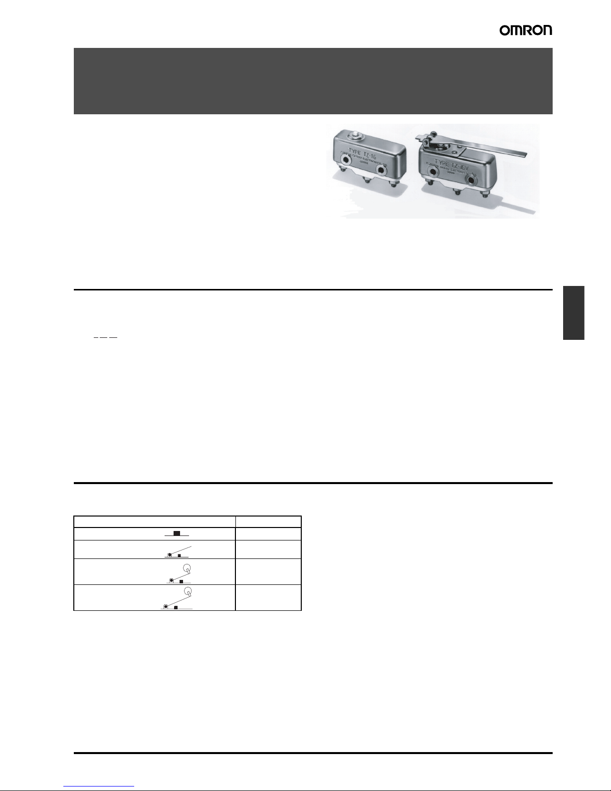
High-temperature Basic Switch TZ F-145
Limit
Switches
High-temperature Basic Switch
TZ
Stable Operation at an Ambient Temperature
of 400°C
• Incorporates a ceramic insulator, cobalt-alloy spring, and special-alloy contact, thus ensuring high contact reliability at high
ambient temperature.
• Smoothly operates at an ambient temperature of 400°C.
Model Number Structure
■ Model Number Legend
1. Rating
1: 1 A, 250 VAC
2. Contact Gap
G: 0.5 mm
3. Actuator
None: Pin plunger
V: Hinge lever
V2: Hinge roller lever
V22: Short hinge roller lever
Ordering Information
■ List of Model
1 2 3
TZ-1G@
Actuator Model
TZ-1G
TZ-1GV
TZ-1GV22
TZ-1GV2
Pin plunger
Hinge lever
Short hinge roller lever
Hinge roller lever
Page 2
F-146 High-temperature Basic Switch TZ
Specifications
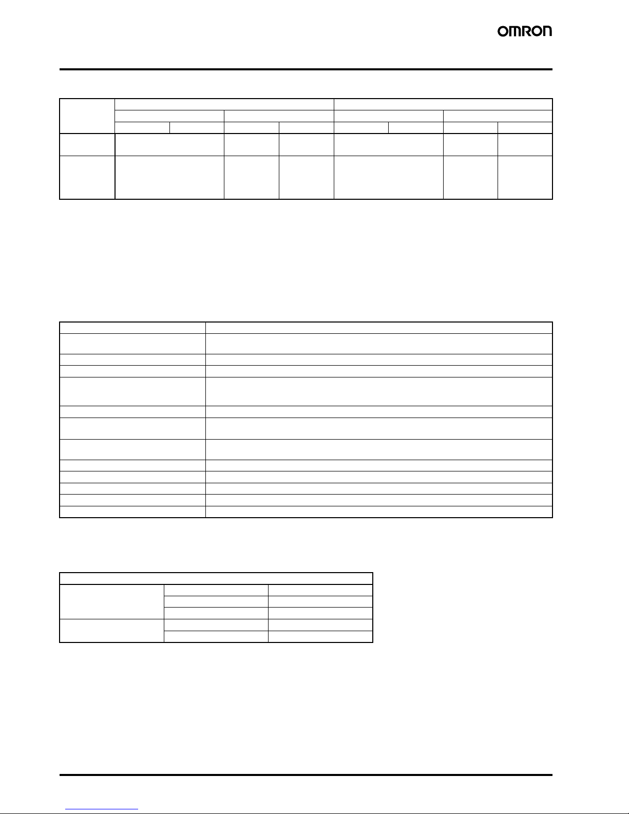
■ Ratings
Note: 1. The above current ratings are the values of the steady-state current.
2. Inductive load has a power factor of 0.4 min. (AC) and a time constant of 7 ms max. (DC).
3. Lamp load has an inrush current of 10 times the steady-state current.
4. Motor load has an inrush current of 6 times the steady-state current.
5. The above ratings are tested under the following conditions.
1. Ambient temperature: 20±2 °C
2. Ambient humidity: 65±5%
3. Switching frequency: 20 times/min
■ Characteristics
Note: 1. This operating speed applies to switches with pin-type pushbuttons.
2. This refers to a malfunction period of 1 ms max.
■ Contact Specifications
Rated voltage Non-inductive load (A) Inductive load (A)
Resistive load Lamp load Inductive load Motor load
NC NO NC NO NC NO NC NO
125 VAC
250 VAC
1
1
0.9
0.45
0.45
0.3
1
1
1.5
0.45
0.75
0.3
8 VDC
14 VDC
30 VDC
125 VDC
1
1
1
0.4
0.9
0.9
0.9
0.05
0.45
0.45
0.45
0.05
1
1
1
0.4
1.5
1.5
1.5
0.05
1.5
1.5
1.5
0.05
Operating speed 0.05 mm to 1 m/s (see note 1)
Operating frequency Mechanical: 60 operations/min
Electrical: 20 operations/min
Insulation resistance 100 MΩ min. (at 500 VDC)
Contact resistance 100 mΩ max. (initial value)
Dielectric strength 1,000 VAC, 50/60 Hz for 1 min between terminals of same polarity
1,500 VAC, 50/60 Hz for 1 min between current-carrying metal parts and ground and between each
terminal and non-current-carrying metal parts
Vibration resistance Malfunction: 10 to 55 Hz, 1.5-mm double amplitude (see note 2)
Shock resistance
Destruction: 500 m/s
2
{50G} max.
Malfunction: 300 m/s
2
{30G} max. (see note 2)
Durability Mechanical: 100,000 operations min.
Electrical: 50,000 operations min.
Degree of protection IP00
Electric shock protection Class I
Ambient temperature Operating: −65°C to 400°C (with no icing)
Ambient humidity Operating: 35% to 85% max.
Weight Approx. 45 to 54 g
Item
Contact Specification Cross bar
Material Platinum alloy
Gap (standard value) 0.5 mm
Inrush current NC 9 A max.
NO 4.5 A max.
Page 3
High-temperature Basic Switch TZ F-147
Limit
Switches
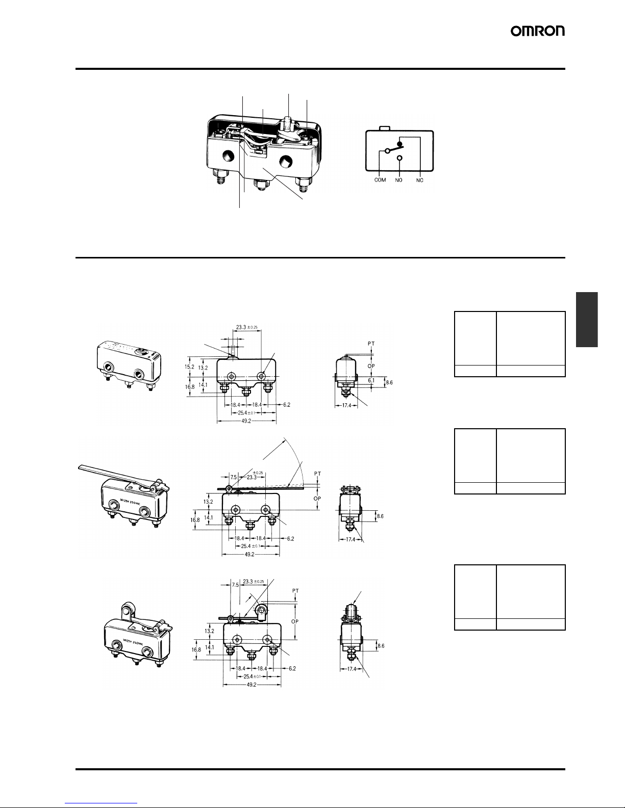
Nomenclature
Dimensions
■ Dimensions and Operating Characteristics
Note: 1. All units are in millimeters unless otherwise indicated.
2. Each dimension has a tolerance of ±0.4 mm unless otherwise specified.
OF max.
RF min.
PT max.
OT min.
MD max.
4.9 N {500 gf}
1.12 N {114 gf}
0.4 mm
0.13 mm
0.15 mm
OP 15.6±0.6 mm
OF max.
RF min.
PT max.
OT min.
MD max.
0.98 N {100 gf}
0.14 N {14 gf}
3.5 mm
4.6 mm
1.3 mm
OP 18±1.2 mm
OF max.
RF min.
PT max.
OT min.
MD max.
2.35 N {240 gf}
0.33 N {34 gf}
1.5 mm
1.9 mm
0.6 mm
OP 28.6±1.2 mm
Fixed contact
Movable spring
Bracket
Ceramic terminal block
Movable contact
Fixed contact
Ceramic
pushbutton
11.4
Pin Plunger
TZ-1G
(Ceramic pushbutton)
3 dia.
Two, 3.56-dia. holes
Three, M3.5
8.2 dia.
11.4
63.5R
Hinge Lever
TZ-1GV
Three, M3.5
(Stainless-steel lever)
Two, 3.56-dia.
holes
11.4
26.2R
Short Hinge Roller Lever
TZ-1GV22
9.5 dia. 4 (stainless-steel roller)
(Stainless-steel lever)
Three, M3.5
Two, 3.56-dia.
holes
Page 4
F-148 High-temperature Basic Switch TZ
Precautions
Refer to the Technical Information for Basic Switches (Cat. No. C122) for common precautions.
■ Correct Use
Handling
The Switch has a ceramic casing. Do not drop the Switch from a
height of 30 cm or more. Doing so will break the casing.
Mounting
Be sure to turn OFF the power supply to the Switch before mounting,
dismounting, wiring, or working on the Switch for maintenance. Not
doing so may result in an electric shock or the Switch may burn.
Mount the switch with M3.5 stainless-steel screws with plane washer
and spring washers securely.
Use M3.5 stainless-steel mounting screws with plane washers or
spring washers to securely mount the Switch. Tighten the screws to
a torque of 0.69 to 0.98 N·m {7 to 10 kgf·cm}.
Mounting Holes
Connect nickel-plated solderless terminals to the TZ. Each terminal
must be secured on the TZ with M3.5 nut.
Make sure that the ceramic case is free of metal powder or other
impurities.
Operation
Do not modify the Actuator and change the operating position.
Make sure that the switching speed is not extremely slow or do not
use the Switch so that the pushbutton will be set to a position
between the FP and OP.
Make sure that the pin-type pushbutton and the switching stroke are
on the same vertical line.
Make sure that the switching frequency or speed is within the specified range.
• If the switching speed is extremely slow, the contact may not be
switched smoothly, which may result in a contact failure or contact
welding.
• If the switching speed is extremely fast, switching shock may dam-
age the Switch soon. If the switching frequency is too high, the contact may not catch up with the speed.
The rated permissible switching speed and frequency indicate the
switching reliability of the Switch.
The life of a Switch is determined at the specified switching speed.
The life varies with the switching speed and frequency even when
they are within the permissible ranges. In order to determine the life
of a Switch model to be applied to a particular use, it is best to conduct an appropriate durability test on some samples of the model
under actual conditions.
Make sure that the actuator travel does not exceed the permissible
OT position. The operating stroke must be set to 70% to 100% of the
rated OT.
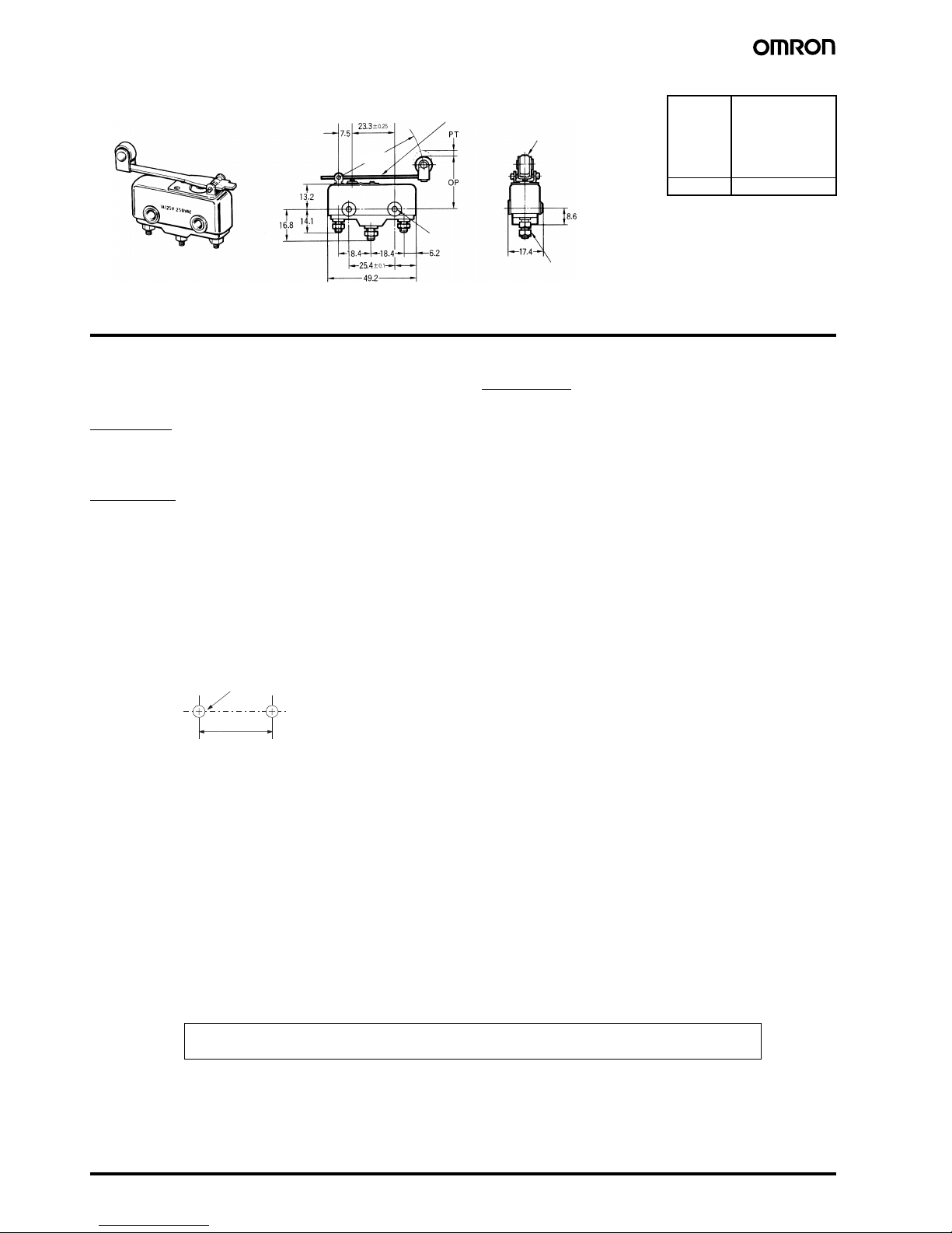
OF max.
RF min.
PT max.
OT min.
MD max.
1.27 N {130 gf}
0.2 N {20 gf}
2.6 mm
3.5 mm
1 mm
OP 28.6±1.2 mm
11.4
48.4R
Hinge Roller Lever
TZ-1GV2
(Stainless-steel lever)
9.5 dia. 4 (stainless-steel roller)
Three, M3.5
Two, 3.56-dia.
holes
25.4 ± 0.1
Two, 3.56-dia. mounting holes or
M3.5 screw holes
In the interest of product improvement, specifications are subject to change without notice.
ALL DIMENSIONS SHOWN ARE IN MILLIMETERS.
To convert millimeters into inches, multiply by 0.03937. To convert grams into ounces, multiply by 0.03527.
Cat. No. B102-E1-02
 Loading...