

Omron SYSMAC NX-CIF, SYSMAC NX, SYSMAC NX-CIF101, SYSMAC NX-CIF105, SYSMAC NX-CIF210 User Manual
Page 1

Machine Automation Controller
NX-series
Communications Interface Units
User’s Manual
NX-CIF
Communications Interface Units
W540-E1-07
Page 2

NOTE
All rights reserved. No part of this publication may be reproduced, stored in a retrieval system, or transmitted, in
any form, or by any means, mechanical, electronic, photocopying, recording, or otherwise, without the prior
written permission of OMRON.
No patent liability is assumed with respect to the use of the information contained herein. Moreover, because
OMRON is constantly striving to improve its high-quality products, the information contained in this manual is
subject to change without notice. Every precaution has been taken in the preparation of this manual. Nevertheless, OMRON assumes no responsibility for errors or omissions. Neither is any liability assumed for damages
resulting from the use of the information contained in this publication.
Trademarks
• Sysmac and SYSMAC are trademarks or registered trademarks of OMRON Corporation in Japan and other
countries for OMRON factory automation products.
• Microsoft, Windows, Windows Vista, Excel, and Visual Basic are either registered trademarks or trademarks of
Microsoft Corporation in the United States and other countries.
• EtherCAT® is registered trademark and patented technology, licensed by Beckhoff Automation GmbH, Germany.
• Safety over EtherCAT® is registered trademark and patented technology, licensed by Beckhoff Automation GmbH,
Germany.
• ODVA, CIP, CompoNet, DeviceNet, and EtherNet/IP are trademarks of ODVA.
• The SD and SDHC logos are trademarks of SD-3C, LLC.
Other company names and product names in this document are the trademarks or registered trademarks of their
respective companies.
Copyrights
Microsoft product screen shots reprinted with permission from Microsoft Corporation.
Page 3

Introduction
Thank you for purchasing an NX-series Communications Interface Unit.
This manual contains information that is necessary to
Units. Please read this manual and make sure you understand the functionality and performance of the
NX-series Communications Interface Unit before you attempt to use it in a control system.
Introduction
use the NX-series Communications Interface
Keep this manual in a safe place where it will be available for
Intended Audience
This manual is intended for the following personnel, who must
tems (an electrical engineer or the equivalent).
• Personnel in charge of introducing FA systems.
• Personnel in charge of designing FA systems.
• Personnel in charge of installing and maintaining FA sy
• Personnel in charge of managing FA systems and facilities.
For
programming, this manual is intended for pers
specifications in international standard IEC 61131-3 or Japanese standard JIS B 3503.
Applicable Products
This manual covers the following
• NX-series Communications Interface Units
NX-CIF
Part of the specifications and re
vant Manuals on
page 6 and Related Manuals on page 27.
reference during
also have knowledge of electrical sys-
stems.
onnel who understand the programming language
products
strictions for the CPU Units are given in other manuals. Refer to Rele-
.
operation.
NX-series Communications Interface Units User’s Manual (W540)
1
Page 4

CONTENTS
CONTENTS
Introduction ..............................................................................................................1
Intended Audience....................................................................................................................................... 1
Applicable Products..................................................................................................................
Relevant Manuals .....................................................................................................6
Manual Structure ......................................................................................................7
Page Structure and Icons ............................................................................................................................ 7
Special Information...................................................................................................................................... 8
Precautions on Terminology..........................................
Terms and Conditions Agreement........................................................................ 10
Warranty, Limitations of Liability................................................................................................................ 10
Application Considerations ........................................................................................................................ 11
Disclaimers .........................................................................................................................
................... 1
.............................................................................. 8
....................... 11
Safety Precautions .................................................................................................12
Precautions for Safe Use....................................................................................... 16
Precautions for Correct Use.................................................................................. 21
Regulations and Standards...................................................................................23
Conformance to EU Directives .................................................................................................................. 23
Conformance to UL and CSA Standards................................................................................................
Conformance to Shipbuilding Standards ................................................................................................... 24
Conformance to KC Certification ............................................................................................................... 24
Software Licenses and Copyrights ...................................................................................................
... 24
......... 24
Unit Versions ..........................................................................................................25
Unit Versions ............................................................................................................................................. 25
Unit Versions and Support Software Versions........................................................................................... 26
Related Manuals .....................................................................................................27
Terminology............................................................................................................31
Revision History .....................................................................................................33
Sections in this Manual .........................................................................................35
Section 1 Features and System Configuration
1-1 Features of Communications Interface Units ..................................................................... 1-2
1-2 System Configuration ...........................................................................................................
1-2-1 System Configuration with CIF Unit Connected to CPU Unit......................................................1-3
1-2-2 System Configuration of Slave Terminals...................................................................................1-5
1-3 Unit Models, Functions, and Support Software.................................................................. 1-7
1-3-1 Unit Model Numbers ...................................................................................................................1-7
1-3-2 Functions.....................................................................................................................
1-3-3 Support Software ........................................................................................................................1-7
1-4 Serial Communications Instructions for the CIF Units ...................................................... 1-8
1-4-1 Serial Communications Instructions for CIF Units.......................................................................1-8
1-4-2 Conditions for Using Serial Communications Instructions for CIF Units .....................................1-8
2
NX-series Communications Interface Units User’s Manual (W540)
1-3
................1-7
Page 5

Section 2 Specifications and Application Procedures
2-1 Specifications ........................................................................................................................ 2-2
2-1-1 General Specifications................................................................................................................ 2-2
2-1-2 Specifications of Individual Units .....................
2-2 Application Procedures ........................................................................................................ 2-5
........................................................................... 2-3
Section 3 Part Names and Functions
3-1 Part Names............................................................................................................................. 3-2
3-1-1 NX-CIF101 and NX-CIF105........................................................................................................ 3-2
3-1-2 NX-CIF210.................................................................................................................................. 3-4
3-2 Indicators ............................................................................................................................... 3-5
3-2-1 TS Indicator ................................................................................................................................ 3-6
3-2-2 Send/Receive Indicators............................................................................................................. 3-7
3-2-3 Appearance Change of the Indicators ........................................................................................3-
CONTENTS
7
Section 4 Installation and Wiring
4-1 Installing NX Units................................................................................................................. 4-2
4-2 Connecting the Power Supply and Ground Wire
4-3 Wiring the Terminals .............................................................................................................
4-3-1 Wiring the Screwless Clamping Terminal Blocks ....................................................................... 4-4
4-3-2 Wiring the D-Sub Connector..................................................................................................... 4-19
4-4 Wiring Communications ..................................................................................................... 4-20
4-4-1 Terminal Arrangement.............................................................................................................. 4-20
4-4-2 Connecting to Serial Communications Devices........................................................................ 4-23
4-4-3 Examples of Recommended RS-232C and RS-422A/485 Wiring ............................................ 4-27
Section 5 I/O Data Specifications
5-1 I/O Data Specifications for NX-CIF101 and NX-CIF105 ...................................................... 5-2
5-2 I/O Data Specifications for NX-CIF210
Section 6 Unit Settings
6-1 Unit Operation Settings ........................................................................................................ 6-2
6-1-1 Communications Specifications.................................................................................................. 6-2
6-1-2 Transmission Buffering............................................................................................................... 6-2
6-1-3 Event Levels ............................................................................................................................... 6-4
6-2 Unit Operation Setting Procedure........................................................................................ 6-5
s ............................................................. 4-3
4-4
................................................................................. 5-3
6-3 Setting the Divided Data Size .............................
Section 7 Serial Communications
7-1 No-protocol Communications .............................................................................................. 7-3
7-2 How Data Is Sent and Received ............................
7-2-1 How Data Is Sent........................................................................................................................ 7-4
7-2-2 How Data Is Received ...........................................................................................................
7-3 Data Used by the Serial Communications Protocol........................................................... 7-6
NX-series Communications Interface Units User’s Manual (W540)
.................................................................. 6-6
............................................................... 7-4
..... 7-5
3
Page 6

CONTENTS
7-4 Examples of Communications between CPU Unit or Communications Master and
7-5 User Programming to Send Data ....................................................................................... 7-27
7-6 User Programming to Receive Data .................................................................................. 7-28
7-7 User Programming to Restart a Port ................................................................................. 7-30
7-8 Communications Performance ................................
7-3-1 Input Notification Data and Output Notification Data................................................................... 7-6
7-3-2 SIDs and SID Responses .........................................................................................................
7-3-3 Input Data Type and Output Data Type ....................................................................................7-10
7-3-4 Send Completed Toggle Bit ......................................................................................................7-10
CIF Unit..............................................................................................................................
7-4-1 Example of Sending Data .........................................................................................................7-13
7-4-2 Example of Receiving Data.......................................................................................................7-16
7-4-3 Simultaneously Sending and Receiving Data ...........................................................................7-19
7-4-4 Example for a Parity Error during Data Reception ...
7-4-5 Example of Control Command Execution .................................................................................7-23
7-5-1 Creating and Outputting Output Notification Data.....................................................................7-27
7-5-2 Checking Input Notification Data...............................................................................................7-27
7-5-3 Processing Send Data ...........................................................................................................
7-6-1 Checking Input Notification Data...............................................................................................7-28
7-6-2 Creating and Outputting Output Notification Data....
7-6-3 Determining Conditions to Start Reception and Conditions for the Completion
of the Reception.....................................................................................................................
7-6-4 Precautions for Writing User Programming to Receive Data ....................................................7-28
.................................................................7-21
................................................................. 7-28
.. 7-7
... 7-13
... 7-27
... 7-28
.......................................................... 7-31
7-8-1 Calculating the Communications Performance.........................................................................7-31
7-8-2 Adjusting Divided Data Sizes to Improve Communications Performance................................. 7-35
7-8-3 Processing When the Send Buffer or Receive Buffer
Becomes Full ........................................7-37
Section 8 Serial Line Monitor
8-1 How the Serial Line Monitor Works ..................................................................................... 8-2
8-1-1 Monitor Data Contents ................................................................................................................8-2
8-1-2 CIF Serial Line Monitor Tab Page...
8-1-3 Processing When a Buffer Becomes Full....................................................................................8-4
8-1-4 Importing and Exporting Monitor Data ........................................................................................8-4
8-1-5 Searching for Text Strings in Monitor Data ...
8-1-6 Creating CSV Files of Monitor Data............................................................................................8-6
8-1-7 Processing for Multiple Units and Ports......................................................................................
8-2 Support Software Operations............................................................................................... 8-7
8-2-1 Displaying the CIF Serial Line Monitor Tab Page .......................................................................8-7
8-2-2 Starting and Stopping Monitoring and Displaying Monitor Data......
Section 9 Troubleshooting
9-1 How to Check for Errors ....................................................................................................... 9-2
9-2 Checking for Errors with the Indicators ...............
9-3 Checking for Errors and Trouble
9-3-1 Checking for Errors from the Sysmac Studio.............................................................................. 9-4
9-3-2 Checking for Errors from Support Software Other Than the Sysmac Studio .............................. 9-5
9-3-3 Event Codes for Errors and Troubleshooting Procedures ..........................................................9-6
9-4 Resetting Errors .................................................................................................................. 9-20
9-5 Troubleshooting Flowchart ...................................
............................................................................................ 8-3
..............................................................................8-5
8-6
............................................8-9
............................................................... 9-3
shooting on the Support Software ............................... 9-4
............................................................. 9-21
Section 10 Maintenance and Inspections
4
NX-series Communications Interface Units User’s Manual (W540)
Page 7

10-1 Cleaning and Inspections ................................................................................................... 10-2
10-1-1 Cleaning.................................................................................................................................... 10-2
10-1-2 Periodic Inspection ................
10-2 Maintenance Procedures .................................................................................................... 10-5
Appendices
A-1 Dimensions ............................................................................................................................A-2
A-1-1 NX-CIF101 and NX-CIF105........................................................................................................A-2
A-1-2 NX-CIF210....................................................................................................................
A-2 Changing NX Objects from a User Program .......................................................................A-4
A-2-1 NX Objects That You Can Change.............................................................................................A-4
A-2-2 Procedure to Change NX Objects ........................
A-3 List of NX Objects..................................................................................................................A-5
A-3-1 Format of NX Object Descriptions .............................................................................................. A-5
A-3-2 NX Objects for the NX-CIF101 and NX-CIF105 .........................................................................A-6
A-3-3 NX Objects for the NX-CIF210 .................................................................................................A-17
A-4 Programming Samples .......................................................................................................A-29
A-4-1 Items Common to all Programming Samples ........................................................................... A-29
A-4-2 Programming Sample 1: Restarting CIF Unit Ports ..................................................................A-32
A-4-3 Programming Sample 2: Sending Data ....................................................................................A-35
A-4-4 Programming Sample 3: Receiving Data...
A-5 Version Information with CPU Units ..................................................................................A-42
A-5-1 Relationship between Unit Versions of Units............................................................................A-42
A-6 Version Information with Communications Coupler Units..............................................A-43
A-6-1 Connection to an EtherCAT Coupler Unit................................................................................. A-43
A-6-2 Connection to an EtherNet/IP Coupler Unit.............................................................................. A-44
CONTENTS
................................................................................................... 10-2
..............A-2
......................................................................A-4
...............................................................................A-38
Index
NX-series Communications Interface Units User’s Manual (W540)
5
Page 8

Relevant Manuals
Relevant Manuals
The table below provides the relevant manuals for the NX-series Communications Interface Units.
Read all of the manuals that are relevant to your system con
of the NX-series Communications Interface Units.
figuration and application to make the most
Other manuals, such as related product manuals, are ne
applications. Refer to Related Manuals o
Manual name Application
NX-series Communications Interface Units User's Manual
NX-series Data Reference Manual Referencing lists of the data that is required to configure systems with NX-series
Learning how to use NX-series Communications Interface Units
Units
n page 27 for the related manuals.
cessary for specific system configurations and
6
NX-series Communications Interface Units User’s Manual (W540)
Page 9
Manual Structure
4-9
4 Installation and Wiring
NJ-series CPU Unit Hardware User’s Manual (W500)
stinU gnitnuoM 3-4
4
stnenopmoC rellortnoC gnitcennoC 1-3-4
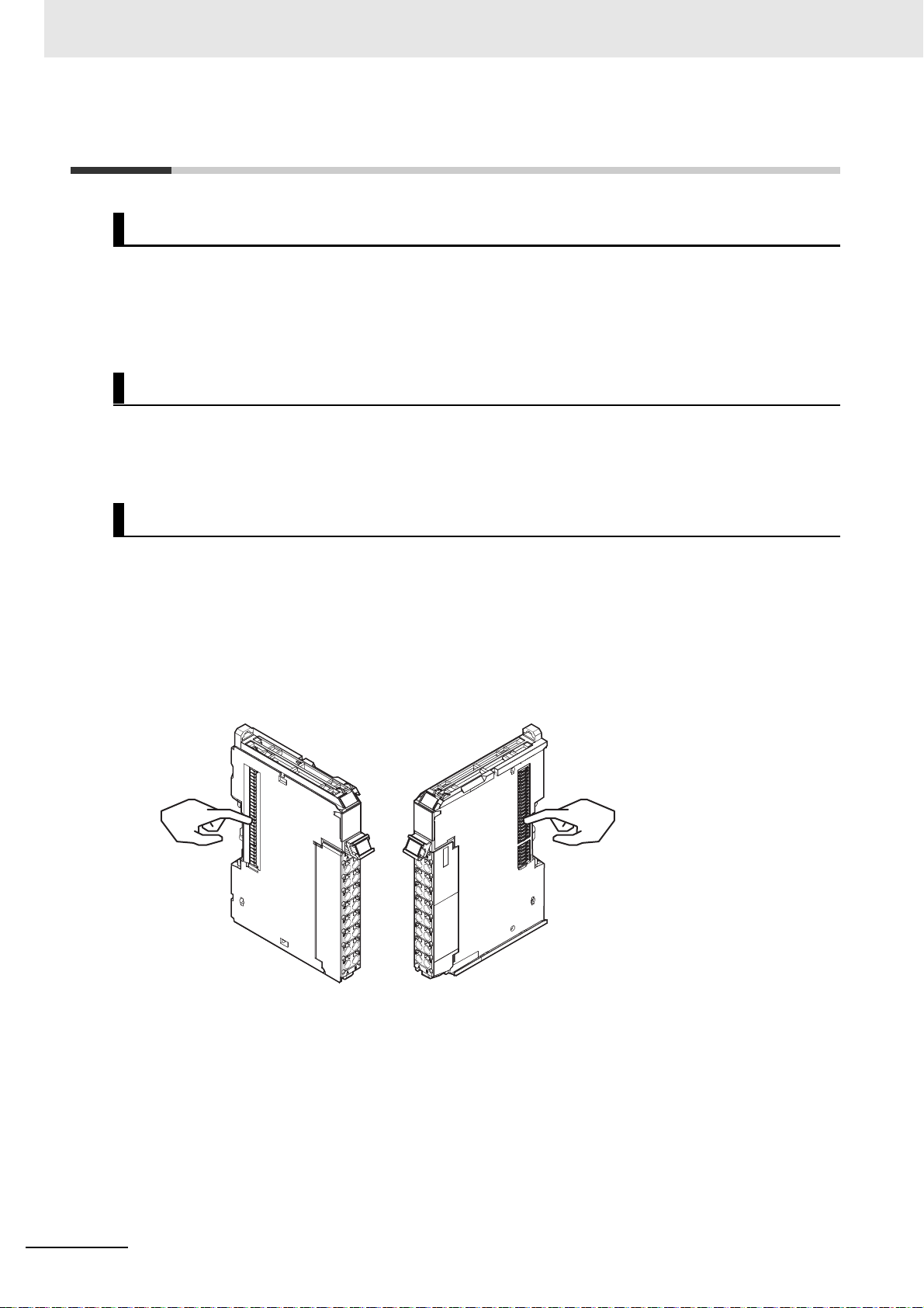
4-3 Mounting Units
The Units that make up an NJ-series Controller can be connected simply by pressing the Units together
and locking the sliders by moving them toward the back of the Units. T he End Cover is connected in t he
same way to the Unit on the far right side of the Controller.
1 Join the Units so that the connectors fit exactly.
2 The yellow sliders at the top and bottom of each Unit lock the Units together. Move the sliders
toward the back of the Units as shown below until they click into place.
Precautions for Correct UsePrecautions for Correct Use
4-3-1 Connecting Controller Components
Connector
Hook
Hook holes
Slider
Lock
Release
Move the sliders toward the back
until they lock into place.
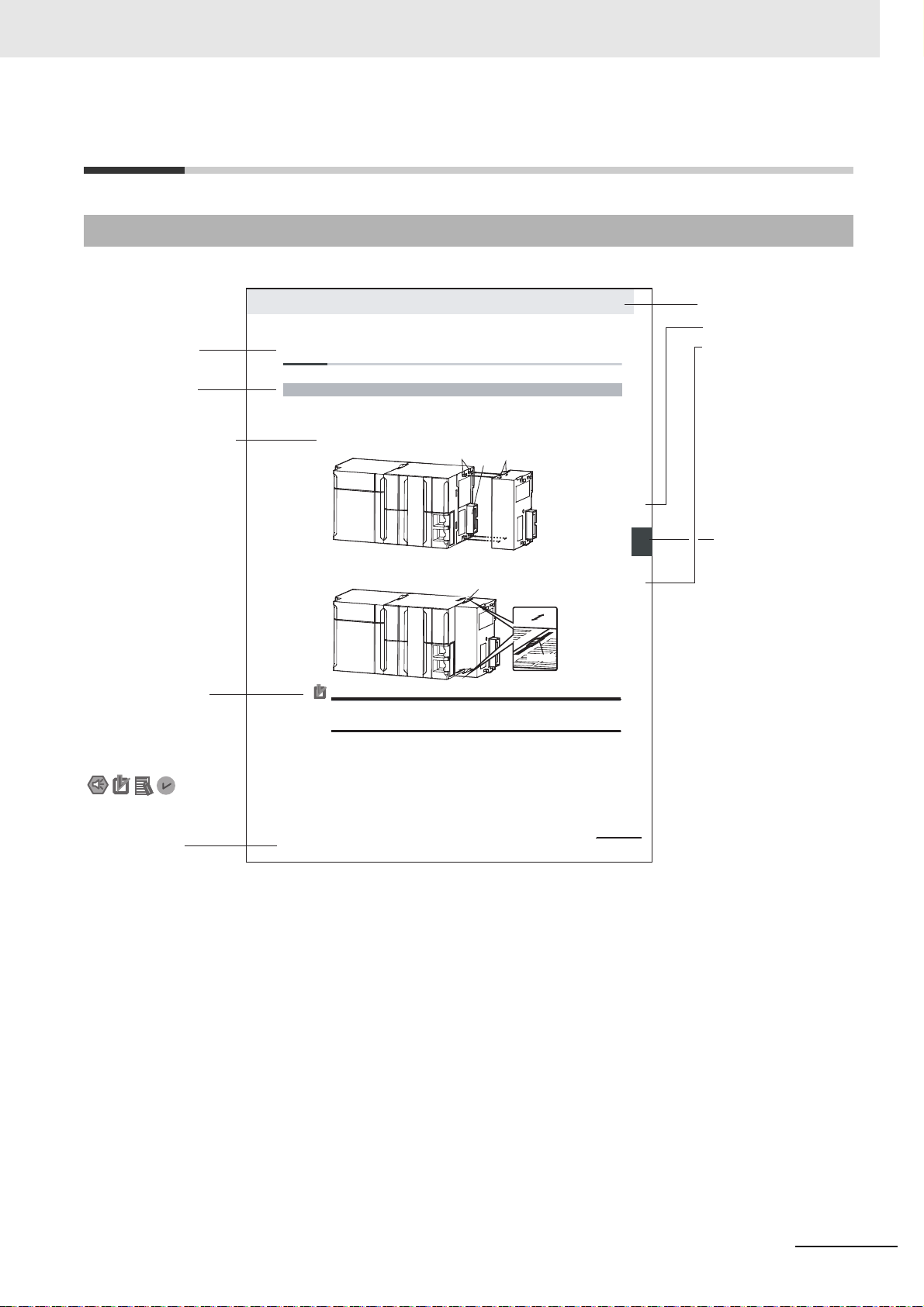
Level 1 heading
Level 2 heading
Level 3 heading
Level 2 heading
A step in a procedure
Manual name
Special information
Level 3 heading
Page tab
Gives the current
headings.
Indicates a procedure.
Icons indicate
precautions, additional
information, or reference
information.
Gives the number
of the main section.
The sliders on the tops and bottoms of the Power Supply Unit, CPU Unit, I/O Units, Special I/O
Units, and CPU Bus Units must be completely locked (until they click into place) after connecting
the adjacent Unit connectors.
Page Structure and Icons
The following page structure and icons are used in this manual.
Manual Structure
Note This illustration is provided only as a sample. It may not literally appear in this manual.
NX-series Communications Interface Units User’s Manual (W540)
7
Page 10
Manual Structure
Precautions for Safe Use
Precautions for Correct Use
Additional Information
Version Information
Special Information
Special information in this manual is classified as follows:
Precautions on what to do and what not to do to ensure safe usage of the product.
Precautions on what to do and what not to do to ensure proper operation and performance.
Additional information to read as required.
This information is provided to increase understanding or make operation easier.
Information on differences in specifications and functionality for CPU Units, Industrial PCs, and
Communications Coupler Units with different unit versions and for different versions of the Sup
port Software is given.
Note References are provided to more detailed or related information.
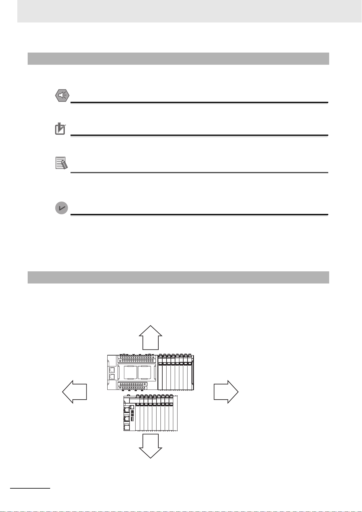
Precautions on Terminology
• In this manual, “download” refers to transferring data from the Support Software to a physical device
and “upload” refers to transferring data from a physical device to the Support Software.
• In this manual, the directions in relation to the Units a
upright installation.
-
re given in the following figure, which shows
Up
RightLeft
• This user's manual refers to the NY-series IPC Machine Controller Industrial Panel PCs and Industri
al Box PCs as simply Industr
8
Down
ial PCs or as NY-series Industrial PCs.
NX-series Communications Interface Units User’s Manual (W540)
Page 11

Manual Structure
• This user's manual refers to the built-in EtherCAT port on an NJ/NX-series Controller or NY-series
Industrial PC as simply a built-in EtherCAT port.
• This user's manual may omit manual names and manua
manuals for CPU Units and Industrial PCs. The following table gives some examples. When necessary, refer to Related Manuals on
mon text for the om
itted contents.
page 27 to determine the appropriate manual based on the com-
Examples:
Manual name Omitted contents Common text
NJ/NX-series CPU Unit Software
User's Manual
NY-series
IPC Machine Controller Industrial
Panel PC / Industrial Box PC
Software User’s Manual
NJ/NX-series CPU Unit Built-in EtherCAT
Port User's Manual
NY-series
IPC Machine Controller Industrial
Panel PC / Industrial Box PC
Built-in EtherCAT Port
User’s Manual
Software user's manual
for the connected CPU
Unit or Industrial PC
User's manual for built-in
EtherCAT port on the
connected CPU Unit or
Industrial PC
• This user's manual may omit manual names and manua
manuals for Communications Coupler Units. If you will use a Communications Coupler Unit, refer to
Related Manuals o
n page 27 to identify the manual for your Unit.
l numbers in places that refer to the user's
Software User's Manual
Built-in EtherCAT port
l numbers in places that refer to the user's
NX-series Communications Interface Units User’s Manual (W540)
9
Page 12

Terms and Conditions Agreement
Terms and Conditions Agreement
Warranty, Limitations of Liability
Warranties
Exclusive Warranty
Omron’s exclusive warranty is that the Products will be free from defects in materials and workmanship for a period of twelve months from the date of sale by Om
writing by Omron). Omron disclaims all other warranties, express or implied.
Limitations
OMRON MAKES NO WARRANTY OR REPRESENTATION, EXPRESS OR IMPLIED, ABOUT
NON-INFRINGEMENT, MERCHANTABILITY OR FITNESS FOR A PARTICULAR PURPOSE OF
THE PRODUCTS. BUYER ACKNOWLEDGES THAT IT ALONE HAS DETERMINED THAT THE
PRODUCTS WILL SUITABLY MEET THE REQUIREMENTS OF THEIR INTENDED USE.
Omron further disclaims all
on infringement by the Products or otherwise of any intellectual property right.
warranties and responsibility of
ron (or such other period expressed in
any type for claims or expenses based
Buyer Remedy
Omron’s sole obligation hereunder shall be, at Omron’s election, to (i) replace (in the form originally
shipped with Buyer responsible for labor charges for removal or replacement thereof) the non-complying Product, (ii) repair the non-complying Product, or (iii)
to the purchase price of the non-complying Product; provided that in no event shall Omron be
responsible for warranty, repair, indemnity or any other claims or expenses regarding the Products
unless Omron’s analysis confirms that the Products were properly handled, stored, installed and
maintained and not subject to contamination, abuse, misuse or inappropriate modification. Return of
any Products by Buyer must be approved in writing by Omron before shipment. Omron Companies
shall not be liable for the suitability or unsuitability or the results from the use of Products in combination with any electrical or electronic components, cir
als or substances or environments. Any advice, reco
writing, are not to be construed as an amendment or addition to the above warranty.
a
See http://www.omron.com/glob
l/ or contact your Omron representative for published information.
mmendations or information given orally or in
repay or credit Buyer an amount equal
uits, system assemblies or any other materi-
c
Limitation on Liability; Etc
OMRON COMPANIES SHALL NOT BE LIABLE
SEQUENTIAL DAMAGES, LOSS OF PROFITS OR PRODUCTION OR COMMERCIAL LOSS IN A
WAY CONNECTED WITH THE PRODUCTS, WHETHER SUCH CLAIM IS BASED IN CONTRACT,
WARRANTY, NEGLIGENCE OR STRICT LIABILITY.
Further, in no event shall liability
which liability is asserted.
of Omron
FOR SPECIAL, INDIRECT, INCIDENTAL, OR CON-
Companies exceed the individual price of the Product on
NY
10
NX-series Communications Interface Units User’s Manual (W540)
Page 13

Application Considerations
Suitability of Use
Omron Companies shall not be responsible for conformity with any standards, codes or regulations
which apply to the combination of the Product in the Buyer’s application or use of the Product. At
Buyer’s request, Omron will provide applicable third party certification documents identifying ratings
and limitations of use which apply to the Product. This information by itself is not sufficient for a complete determination of the suitability
tem, or other application or use. Buyer shall be solely r
the particular Product with respect to Buyer’s application, product or system. Buyer shall take application responsibility in all cases.
NEVER USE THE PRODUCT FOR AN APPLICATION
PROPERTY OR IN LARGE QUANTITIES WITHOUT ENSURING THAT THE SYSTEM AS A WHOLE
HAS BEEN DESIGNED TO ADDRESS THE RISKS, AND THAT THE OMRON PRODUCT(S) IS
PROPERLY RATED AND INSTALLED FOR THE INTENDED USE WITHIN THE OVERALL EQUIPMENT OR SYSTEM.
of the Product
Terms and Conditions Agreement
in combination with the end product, machine, sys-
esponsible for determining appropriateness of
IN
VOLVING SERIOUS RISK TO LIFE OR
Programmable Products
Omron Companies shall not be responsible for the use
any consequence thereof.
Disclaimers
Performance Data
Data presented in Omron Company websites, catalogs and other materials is provided as a guide for
the user in determining suitability
Omron’s test conditions, and the user must correlate it to actual application requirements. Actual performance is subject to the Omron’s Warranty
Change in Specifications
Pro
duct specifications and accessories may be changed a
reasons. It is our practice to change part numbers when published ratings or features are changed, or
when significant construction changes are made. However, some specifications of the Product may be
changed without any notice. When in doubt, special part numbers may be assigned to fix or establish
key specifications for your application. Please consult with your Omron’s representative at any time to
confirm actual specifications of purchased Product.
r
’s programming of a programmable Product, or
and does not constitute a warranty. It may represent the result of
and Limitations of Liability.
t any time based on improvements and other
Errors and Omissions
Information presented by Omron Companies has been checked and is believed to be accurate; however, no responsibility is assumed for clerical, typographic
NX-series Communications Interface Units User’s Manual (W540)
al or
proofreading errors or omissions.
11
Page 14
Safety Precautions
WARNING
Caution
Indicates a potentially hazardous situation which, if not avoided, could
result in death or serious injury. Additionally, there may be severe property damage.
Indicates a potentially hazardous situation which, if not avoided, may
result in minor or moderate injury, or property damage.
Safety Precautions
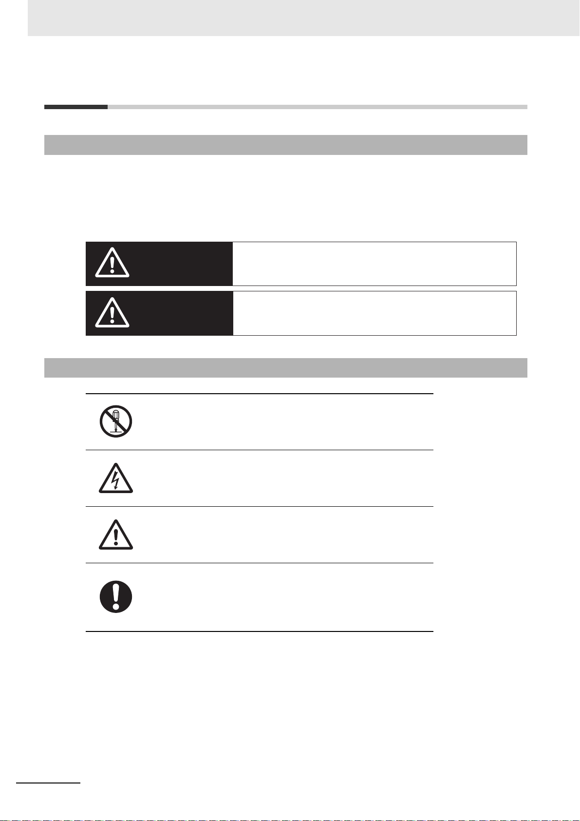
Definition of Precautionary Information
The following notation is used in this manual to provide precautions required to ensure safe usage of an
NX-series Communications Interface Unit.
The safety precautions that are provided are extrem
information provided in all safety precautions.
The following notation is used.
Symbols
ely important to safety. Always read and heed the
The circle and slash symbol indicates operations that you must not do.
The specific operation is shown in the circle and explained in text.
This example indicates prohibiting disassembly.
The triangle symbol indicates precautions (including warnings).
The specific operation is shown in the triangle and explained in text.
This example indicates a precaution for electric shock.
12
The triangle symbol indicates precautions (including warnings).
The specific operation is shown in the triangle and explained in text.
This example indicates a general precaution.
The filled circle symbol indicates operations that you must do.
The specific operation is shown in the circle and explained in text.
This example shows a general precaution for something that you must
.
do
NX-series Communications Interface Units User’s Manual (W540)
Page 15
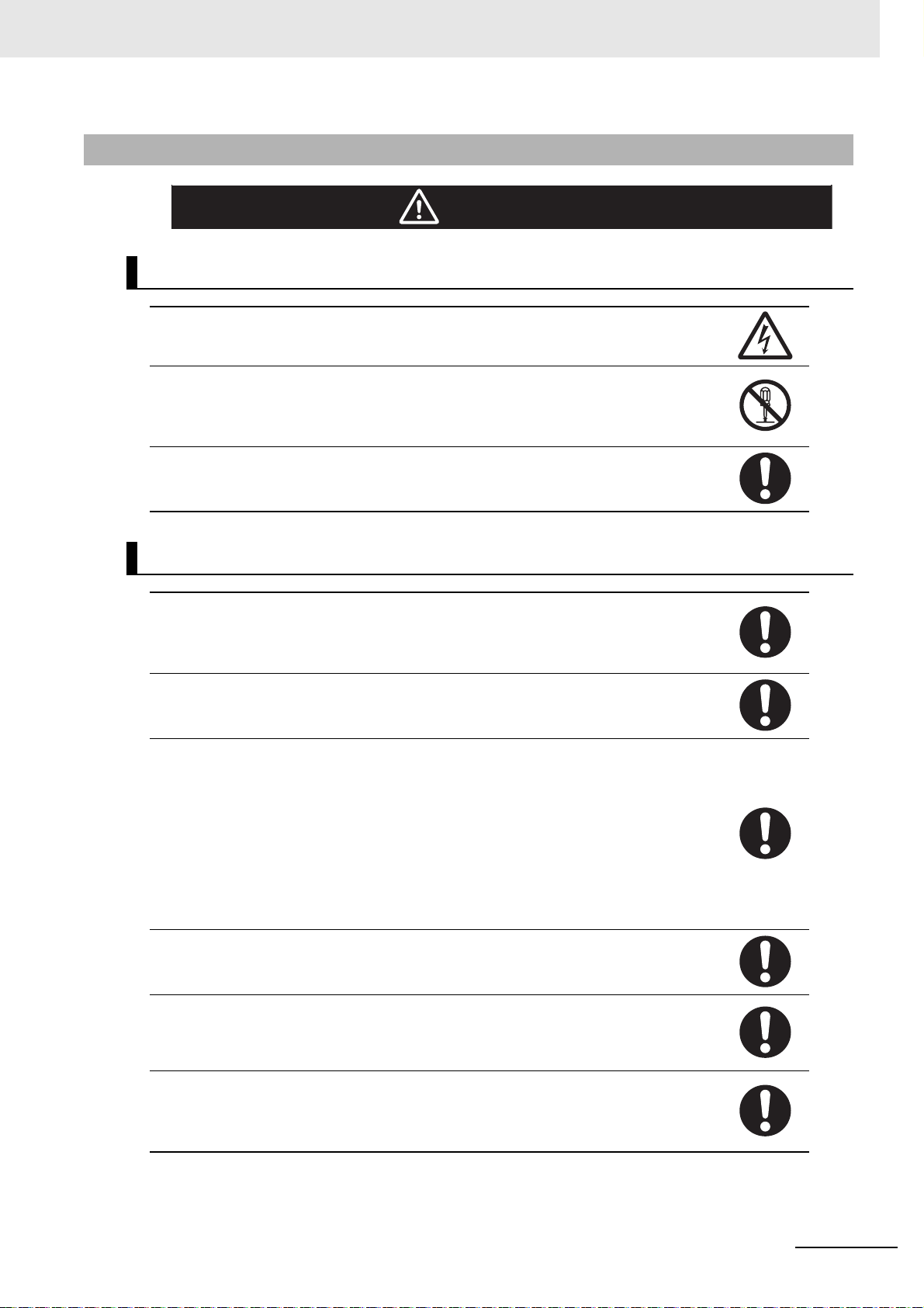
Warning
WARNING
During Power Supply
Do not touch the terminal section while power is ON.
Electric shock may occur.
Do not attempt to take any Unit apart.
In particular, high-voltage parts are present in
plied or immediately after power is turned OFF.
electric shock. There are sharp parts inside the Unit that may cause injury.
Do not place heavy objects on top of the cables.
Doing so may break the cables.
its that supply power while power is sup-
Un
Touching any of these parts may result in
Safety Precautions
Fail-safe Measures
Provide safety measures in external circuits to ensure safety in the system if an abnormality
occurs due to malfunction of the CPU Unit, Industrial PCs, other Units, or slaves or due to
other external factors affecting operation.
Not doing so may result in serious accidents due to incorrect operation.
Emergency stop circuits, interlock circuits, limit circuits, and similar safety measures must
be provided in external control circuits.
The CPU Unit or Industrial PCs will turn OFF all outputs from Output Units in the following
cases. The remote I/O slaves will operate according to the settings in the slaves.
• If a power supply error occurs.
• If the power supply connection becomes faulty.
• If a CPU watchdog timer error or CPU reset occurs.
• If a Controller error in the
• While the CPU Unit is on standby until RUN mode is
External safety measures must be provided
cases.
The outputs may remain ON or OFF due to deposition or burning of the output relays or
destruction of the output transistors. As a countermeasure for such problems, external
safety measures must be provided to ensure safe operation of the system.
If external power supplies for slaves or other de
voltage will drop, outputs will turn OFF, and the system may be unable to read inputs. Provide external safety measures in controls with
as required so that the system operates safely in such a case.
You must take fail-safe measures to ensure safety in the event of incorrect, missing, or
abnormal signals caused by broken signal lines, momentary power interruptions, or other
causes.
Not doing so may result in serious accidents due to incorrect operation.
r fault level occurs.
majo
entered after the power is turned ON
to ensure safe operation of the system in such
vices are overloaded or short-circuited, the
itoring of external power supply voltage
mon
NX-series Communications Interface Units User’s Manual (W540)
13
Page 16
Safety Precautions
Caution
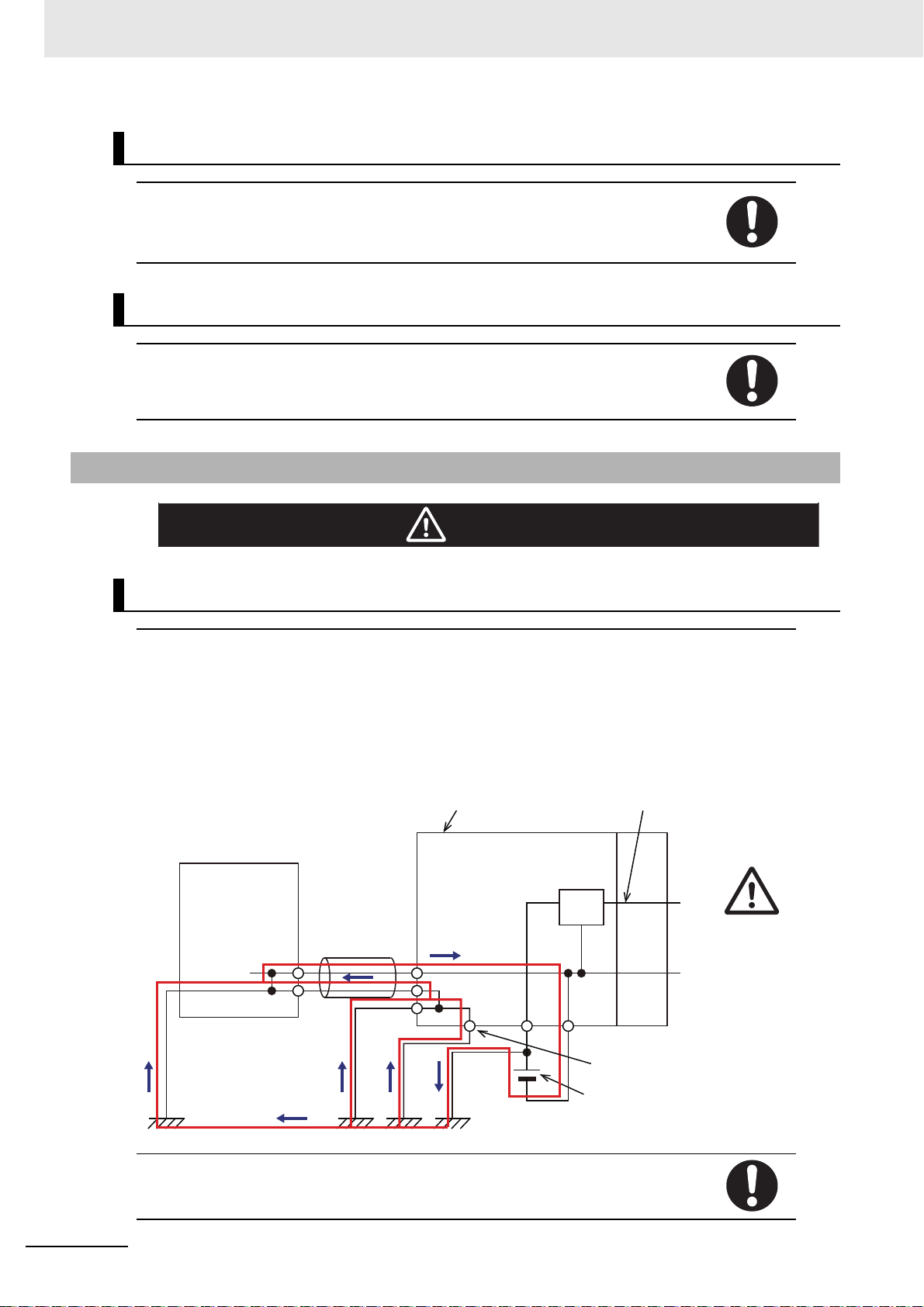
Peripheral device
(e.g., computer)
Non-isolated DC
power supply
(internal power
supply circuit)
0 V
Peripheral
device cable
Communications Coupler Unit
NX Unit
power supply
Unit power
supply
Ground terminal
24 V
Voltage and Current Inputs
Make sure that the voltages and currents that are input to the Units and slaves are within
the specified ranges.
Inputting voltages or currents that are outside of the specified ranges may cause accidents
or fire.
Transferring
Always confirm safety at the destination node before you transfer Unit configuration information, parameters, settings, or other data from tool
The devices or machines may operate unexpectedly, rega
the Controller.
Cautions
s such as the Sysmac Studio.
rdless of the operating mode of
Wiring
When you connect a computer or other peripheral device to a Communications Coupler
Unit or Communications Interface Unit that has a non-isolated DC power supply, either
ground the 0-V side of the external power supply (i.e. Unit power supply) or do not ground it
at all.
If the peripheral devices are grounded incorrectly, the
power supply) may be short-circuited.
Never ground the 24-V side of the power supply, as
externa
shown in the following figure.
l power supply (i.e. Unit
14
Tighten cable screws to the specif
tion. Ask the cable manufacturer for the spec
ied torque. Loose screws may result in fire or malfunc-
ified torque for the screws.
NX-series Communications Interface Units User’s Manual (W540)
Page 17

Safety Precautions
Online Editing
Execute online editing only after confirming that no adverse effects will be caused by deviations in the timing of I/O. If you perform online editing, t
the task period, I/O may not be refreshed with external devices, input signals may not be
read, and output timing may change.
he task execution time may exceed
NX-series Communications Interface Units User’s Manual (W540)
15
Page 18
Precautions for Safe Use
Precautions for Safe Use
Transporting
• When transporting any Unit, use the special packing box for it.
Also, do not subject the Unit to excessive vibration or shock during transportation.
• Do not drop any Unit or subject it to abnormal vibration or shock.
Doing so may result in Unit malfunct
Mounting
• Mount terminal blocks and connectors only after checking the mounting location carefully.
• Be sure that the terminal blocks, expansion cables, and other it
locked into place.
ion or burning.
ems with locking devices are properly
Installation
• Always turn OFF the power supply before inst
may malfunction or may be damaged.
• Always turn OFF the Unit power supp
• Do not apply labels or tape to the Unit. When the Units are installed or removed, adhesive or scraps
ma
y adhere to the pins in the NX bus connector, which may result in malfunctions.
• Do not touch the pins in the NX bus connector on the Unit.
connector, which may result in malfunctions.
ly and I/O power supply before you remove the NX Unit.
NG
alling the Unit. If the power supply is not OFF, the Unit
Dirt may adhere to the pins in the NX bus
NG
16
Example: NX Unit (12 mm width)
NX-series Communications Interface Units User’s Manual (W540)
Page 19
Precautions for Safe Use
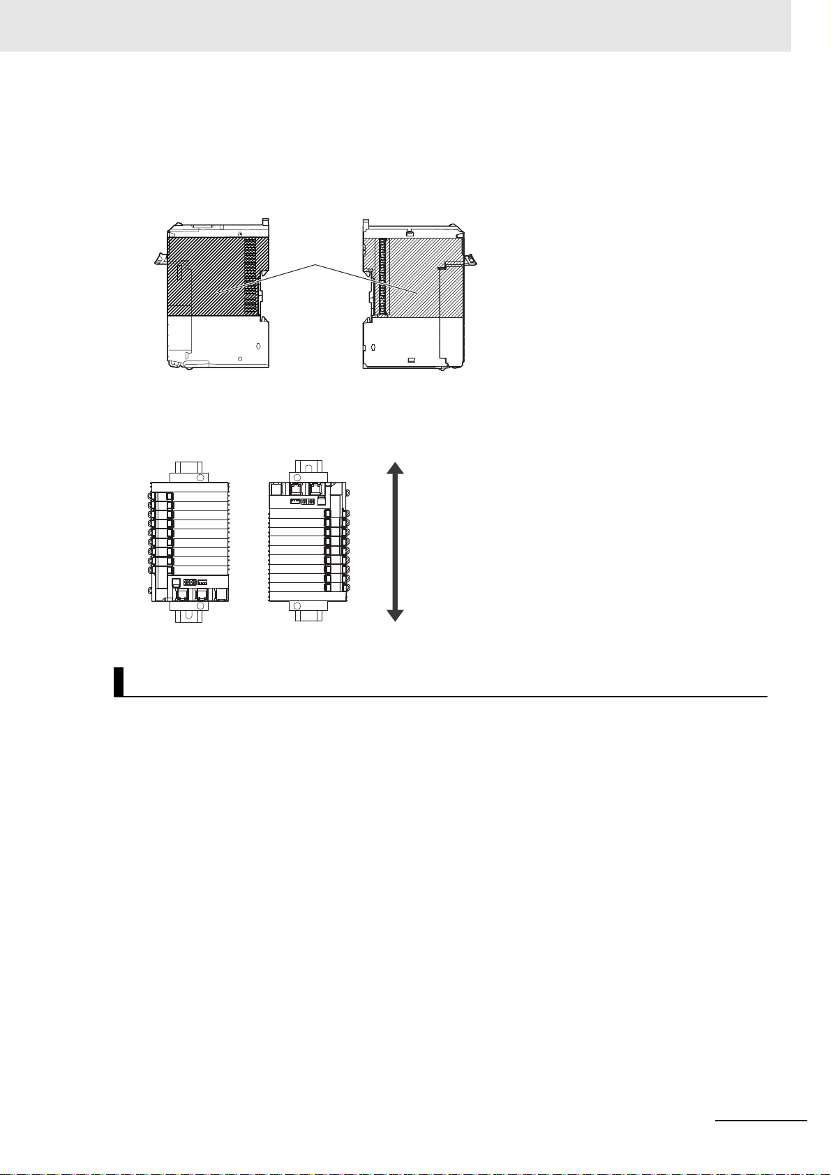
Restricted
region (shaded
portion)
Up
Down
• Do not write on an NX Unit with ink within the restricted region that is shown in the following figure.
Also do not get this area dirty. When the Unit is installed or removed, ink or dirt may adhere to the
pins in the NX bus connector, which may result in malfunctions in the CPU Rack or the Slave Terminal.
Refer to the user’s manual for the connected CPU Unit
or Communic
restricted region of CPU Unit and Communications Coupler Unit.
ations Coupler Unit for the
• For the installation orientations in the following figure
, support the cables, e.g., with a duct, so that the
End Plate on the bottom is not subjected to the weight of the cables. The weight of the cables may
cause the bottom End Plate to slide downward so that the Slave Terminal is no longer secured to the
DIN Track, which may result in malfunctions.
Wiring
b
• Double-check all switches and other settings and dou
correct before turning ON the power supply.
Use the correct wiring parts and tools when you wire the system.
• Observe the following precautions when you wire communications cables. The communications
cables may be
broken or the Units may malfunction.
a) Do not fold communications cables.
b) Do not pull on communications cables with excess
that they are not pulled on excessively.
c) Do not place heavy objects on top of
communications cables.
For a terminal block, cable ties can be used to secure the communications cable.
• When wiring or installing the Units, do not allow metal fragments to enter the Unit
le-check all wiring to make sure that they are
ive force. Secure communications cables so
s.
NX-series Communications Interface Units User’s Manual (W540)
17
Page 20
Precautions for Safe Use
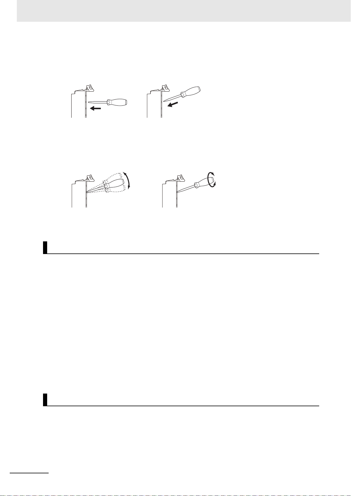
NG
NG
• Do not press the flat-blade screwdriver straight into the release holes on a screwless clamping terminal block. Doing so may break the terminal block.
NG OK
• When you insert a flat-blade screwdriver into a release ho
press it down with a force of 30N or less. Applying excessive force may damage the terminal block.
• Do not incline or twist the flat-blade sc
terminal block. Doing so may damage the terminal block.
• If you use reed switches for the input contacts for AC Input Units, use s
rent of 1 A or greater. If the capacity of the reed switches is too low,
tacts.
rewdriver while it is in a release hole on a screwless clamping
le on a scr
ewless clamping terminal block,
witches with an allowable cur-
inrush current may fuse the con-
Power Supply Design
• Use all Units within the I/O power supply ran
• The I/O power supply current for the CPU Rack with an N
range specified for the CPU Unit model. For example, use the NX1P2 CPU Unit with a current of 4 A
or less. Using the currents that are outside of the specifications may cause failure or damage. Refer
to the user’s manual for the connected CPU Unit for the I/O power supply current for the CPU Unit
model.
• Supply sufficient power according to the contents of this manual.
• Use the power supply voltage that is specified in this manual.
• Do not apply voltages that exceed the rated value to any Input Unit.
• Do not apply voltages or connect loads to the Output Units
ings.
• Inrush current occurs when the power supply is turned ON. When selecting fuses or breakers for
ternal circuits, consider their fusing and detection characteristics as well as the above precautions
ex
and allow sufficient margin in shut-off performance.
• Install external breakers and take other safety measures
external wiring.
ges that are given in the specifications.
X-series CPU Unit should be within the
o
r slaves in excess of the maximum rat-
against short-circuiting and overcurrents in
18
Turning ON the Power Supply
• When you set the Operating Mode at Startup, co
NX-series Communications Interface Units User’s Manual (W540)
nfirm that no adverse effect will occur in the system.
Page 21

Precautions for Safe Use
Actual Operation
• Before you start operation, always register the NX Units that are connected to the Communications
Coupler Unit in the host communications master as the Unit configuration information.
• Check the user program, data, and parameter settings for proper execution before you use them for
actual op
• If you change the fail-soft operation setting, the outp
change. Confirm safety before you change the fail-soft operation setting.
• If you use fail-soft operation, write programming to dete
such programming, the user program cannot distinguish between Units for which I/O refreshing is
continued and Units for which I/O refreshing is stopped.
• Before you operate the controlled system with the user program, make sure that doing so will not
adversely
eration.
ut status when the error occurs may also
rmine whether Unit I/O data is valid. Without
affect the controlled system.
Turning OFF the Power Supply
• Do not disconnect the cable or turn OFF the power supply to the Controller or a Slave Terminal when
downloa
• Always turn OFF the external power supply to the
Mounting or removing an NX Unit, Communications Coupler Unit,
Assembling Units
ding data or the user program from the Support Software.
Units before attempting any of the following.
CPU Unit, or Industrial PC
Setting DIP switches or rotary switches
Connecting or wiring cables
Attaching or removing terminal blocks or connectors
for
Units that supply power continue to supply power to the Units
power supply is turned OFF. The PWR indicator remains lit as long as power is supplied. Confirm that
the PWR indicator is not lit before you perform any of the above.
up to several seconds after the
Operation
• Confirm that the controlled system will not
lowing operations.
Changing the operating mode of the CPU Unit or the Indu
the Operating Mode at Startup)
Changing the user program or settings
Changing set values or present values.
Forced Refreshing
• Always sufficiently check the safety at the connecte
slave or Unit.
be adversely affected before you perform any of the fol-
strial PC (including changing the setting of
d
devices before you change the settings of a
General Communications
• Do not exceed the ranges that are given in the spec
number of connected Units.
• Refer to the user’s manual for the Communications Couple
communications with the connected Communications Coupler Unit.
Disposal
• Dispose of the product according to local ordin
NX-series Communications Interface Units User’s Manual (W540)
ifications for the communications distance and
r Unit for precautions for the safe use of
ances as they apply.
19
Page 22

Precautions for Safe Use
Using Communications Interface Units
• Always check polarity before connecting RS-422A/485 cables. The polarity of the SDA/SDB and
RDA/RDB terminals and signals are reversed for some remote devices.
20
NX-series Communications Interface Units User’s Manual (W540)
Page 23

Precautions for Correct Use
Storage, Mounting, and Wiring
• Follow the instructions in this manual to correctly perform installation and wiring.
• Do not operate or store the Units in the following locations. Doing so ma
operation stopping, or in burning.
Locations subject to direct sunlight
Locations subject to temperatures or humidity outside the
Precautions for Correct Use
y result in malfunction, in
range specified in the specifications
Locations subject to condensation as the result
Locations subject to corrosive or flammable gases
Locations subject to dust (especially iron dust) or salts
Locations subject to exposure to water, oil, or chemicals
Locations subject to shock or vibration
• Take appropriate and sufficient countermeasures during installation in the following
Locations subject to strong, high-frequency noise
Locations subject to static electricity or other forms of noise
Locations subject to strong electromagnetic fields
Locations subject to possible exposure to radioactivity
Locations close to power lines
• Before touching a Unit, be sure to first touch
static build-up.
• Use the rated power supply voltage for the Units that supp
ensure that the specified power with the rated voltage and frequency is supplied in places where the
power supply is unstable.
• Install the Units away from sources of heat and ensure proper ventilation. Not doing so may result in
malfunction
• Do not allow foreign matter to enter the openings in the U
electric shock, or failure.
• Always mount an End Cover to the end of the EtherCAT Sla
the EtherCAT Slave Terminal. Not attaching the End Cover may result in malfunction or failure of the
EtherCAT Slave Terminal.
• After you mount the Slave Terminal, always install an End Plate on each side of the Slave Terminal
secure the Slave Terminal. If you do not secure it, the Slave Terminal may be damaged or mal-
to
function.
• Check the connector orientation and the socket and plug shapes before you connect the D-Sub connector. If the connector is not connected correc
• If you use the RS-422A/485 port, check the polarity befo
SDA/SDB and RDA/RDB terminals and signals are reversed for some remote devices. If the polarity
is not correct, malfunctions may occur.
• If you use the RS-422A/485 port, use either two-wire
them at the same time. If you use two-wire and four-wire connections at the same time, malfunctions
may occur.
• If you use the RS-422A/485 port, ground the shield only at the CIF Unit.
end of the cable. If you ground both ends of the cable, a difference in electrical potential between the
two grounds may damage the equipment.
, in operation stopping, or in burning.
of severe changes in temperature
l
ocations.
a
grounded metallic object in order to discharge any
ly power. Take appropriate measures to
nit. Doing so may result in Unit burning,
ve Terminal to protect the last NX Unit in
tly,
malfunctions may occur.
re you connect the cable. The polarity of the
or four-wire connections. Do not use both of
Do not ground it at the other
NX-series Communications Interface Units User’s Manual (W540)
21
Page 24

Precautions for Correct Use
Transferring Data
Before you transfer the communications settings to the Unit, confirm that the controlled system will not
be adversely affected.
Actual Operation
• If you change the event level of an error, the output status when the error occurs may also change.
irm safety before you change an event level.
Conf
• Do not exceed the NX Unit power supply capacity. If you ex
failure or malfunction may occur.
• Use CPU Unit, Communications Coupler Unit, and Suppor
Unit. If you use versions that do not support the CIF Unit, malfunctions may occur.
Turning OFF the Power Supply
• Do not turn OFF the power supply while data is being transferred.
• Do not turn OFF the power supply while parameters are being
cations Coupler Unit or NX Units.
ceed the NX Unit power supply capacity,
t Software versions that support the CIF
written to the CPU Unit, the Communi-
General Communications
• Refer to the user’s manual for the Communications Coup
communications with the connected Communications Coupler Unit.
ler Unit for precautions for the correct use of
Unit Replacement
• When removing an NX Unit, remove multiple Units to
remove. If you attempt to remove only one Unit, it is stuck and hard to pull out.
gether which include the one you want to
22
NX-series Communications Interface Units User’s Manual (W540)
Page 25

Regulations and Standards
Conformance to EU Directives
Applicable Directives
• EMC Directives
• Low Voltage Directive
Concepts
EMC Directives
OMRON devices that comply with EU Directives also conform to the related EMC standards so that
they can be more easily built into other devices or the overall machine. The actual products have
been checked for conformity to EMC standards.*1
Whether the products conform to the standards in th
be checked by the customer. EMC-related performance of the OMRON devices that comply with EU
Directives will vary depending on the configuration, wiring, and other conditions of the equipment or
control panel on which the OMRON devices are installed. The customer must, therefore, perform
the final check to confirm that devices and the overall machine conform to EMC standards.
e syste
Regulations and Standards
m used by the customer, however, must
*1. Applicable EMC (Electromagnetic Compatibility) standards are as follows:
EMS (Electromagnetic Susceptibility): EN 6113
EMI (Electromagnetic Interference): EN 61131-2 (Radiated emission
1-2
: 10-m regulations).
Low Voltage Directive
Always ensure that devices operating at voltages of 50 to 1,000 VAC and 75 to 1,500 VDC meet the
required safety standards. The applicable directive is EN 61010-2-201.
Conformance to EU Directives
The NX-series Units comply with EU Directives. To ensure that the machine or device in which the
NX-series Units are used complies with EU Directives, the following precautions must be observed.
• The NX-series Units must be installed within
• The SELV requirements must be satisfied for the DC
Unit power supplies and I/O power supplies for the NX-series Units.
EMC standard compliance was confirmed for the recommended Power Supplies. Refer to the
er’s manual for the connected CPU Unit for the recommended power supplies for the CPU
us
Rack with an NX-series CPU Unit. Refer to the user’s manual for the connected Communications
Coupler Unit for the recommended power supplies for the Slave Terminal.
U
• NX-series Units that comply with E
(EN 61131-2). Radiated Emission characteristics (10-m regulations) may vary depending on the
configuration of the control panel used, other devices connected to the control panel, wiring, and
other conditions.
You must therefore confirm that the overall machine
are used complies with EU Directives.
• You must use power supplies with an output hold time of
plies that are connected as the Unit power supplies and I/O power supplies for the NX-series
Units.
Directives also conform to the Common Emission Standard
a control panel.
power supplies that are connected as the
or equipment in which the NX-series Units
10 ms or longer for the DC power sup-
NX-series Communications Interface Units User’s Manual (W540)
23
Page 26
Regulations and Standards
• This is a Class A product (for industrial environments). In a residential environment, it may cause
radio interference. If radio interference occurs, the user may be required to take appropriate measures.
Conformance to UL and CSA Standards
Some NX-series products comply with UL and CSA standa
complies with UL or CSA standards and the machinery or system in which you use the NX-series product must also comply with the standards, refer to the Instru
The Instruction Sheet provides the application conditions for complying with the standards.
Conformance to Shipbuilding Standards
Some NX-series products comply with ship
complies with shipbuilding standards and the machinery or system in which you use the NX-series
product must also comply with the standards, consult with your OMRON representative. Application
conditions are defined according to the installation location. Application may not be possible for some
installation locations.
For usage conditions for shipbuilding standards, refer to Co
user's manual for the CPU Unit or Communications Coupler Unit to which NX Units are connected.
Note that the usage conditions are provided in the re
mance to shipbuilding standards is confirmed.
building standards. If you use an NX-series product that
Conformance to KC Certification
Observe the following precaution if you use NX-series Units
rds. If you use an NX-series product that
ction Sheet that is provided with the product.
nform
ance to Shipping Standards in the
levant user's manuals for Units whose confor-
in Korea.
Class A Device (Broadcasting Communications Dev
This device obtained EMC registration for
other than homes.
Sellers and/or users need to take note of this.
Software Licenses and Copyrights
This product incorporates certain third party software.
with this software is available at http://www.fa.omron.co.jp/nj_info_e/.
24
ice for Office Use)
office use (Class A), and it is intended to be used in places
The license and copyright information associated
NX-series Communications Interface Units User’s Manual (W540)
Page 27
Unit Versions
LOT No.
Lot number and unit version
Unit versionLot number
Unit model number
This section describes the notation that is used for unit versions, the confirmation method for unit versions, and the relationship between unit versions and Support Software versions.
Unit Versions
A “unit version” has been introduced to manage the Units in the NX Series according to differences in
functionality accomp
An example is provided below for Communications Coupler Units and NX Units.
used for the unit versions of CPU Units or Industrial PCs and the confirmation method for unit versions,
refer to the user's manual for each Unit.
Notation of Unit Versions on Products
anying Unit upgrades.
Unit Versions
For the notation that is
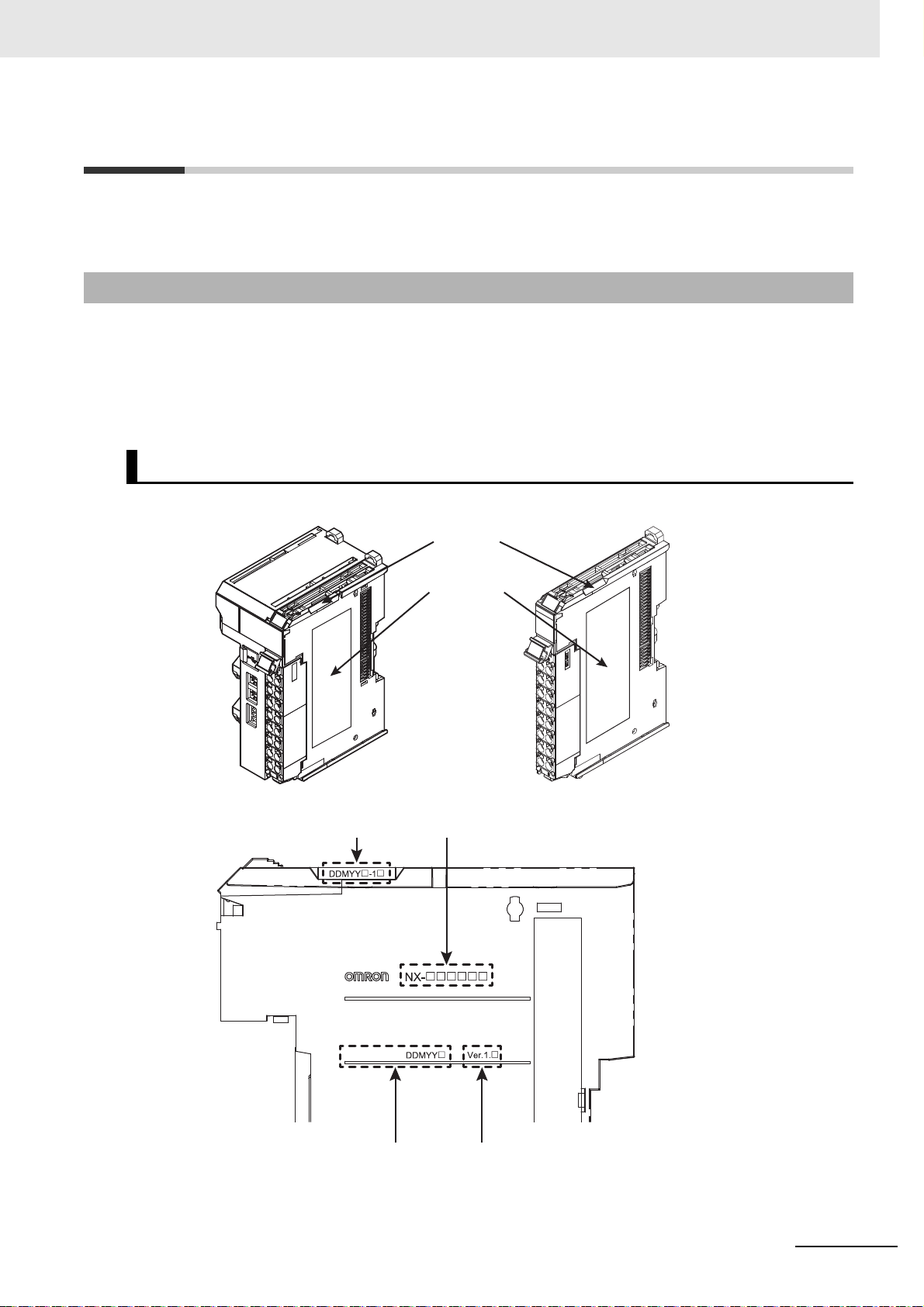
The unit version is given with the Unit specifications on the side
Notched
area
Unit
specifications
of the Unit or in the notched area.
NX-series Communications Interface Units User’s Manual (W540)
25
Page 28

Unit Versions
The following information is provided in the Unit specifications on the Unit.
Unit model number Gives the model of the Unit.
Unit version Gives the unit version of the Unit.
Lot number Gives the lot number of the Unit.
The following information is provided in the notched area on the Unit.
Lot number and unit version
Name Function
DDMYY: Lot numbe
“M” gives the month (1 to 9: January to September,
December)
Name Function
Gives the lot number and unit version of the Unit.
DDMYY: Lot number, : Used by OMRON.
•
“M” gives the month (1 to 9: January to September, X: October, Y: November, Z:
December)
•1: Unit version
Th
e decimal portion of the unit version is omitted. (It i
fications.)
r, : Used by OMRON.
X: October, Y: November, Z:
s provided in the Unit speci-
Confirming Unit Versions with the Support Software
If your NX Unit is connected to a CPU Unit, refer to the
confirmation method for the unit version of the NX Unit.
If your NX Unit is connected to a Communications Coupler
nected Communications Coupler Unit for the confirmation
cations Coupler Unit and NX Unit.
user’s manual of the connected CPU Unit for the
Unit, refer to the user’s manual of the con-
method for the unit version of the Communi-
Unit Versions and Support Software Versions
The functions that are supported depend on the unit version of the Unit. The version of Support Software that supports the functions that were added for an upgrade is required to use those functions.
Refer to A-5 Version Information with CPU Units on
nications Coupler Units on page
A-43 for the functions that are supported by each unit version.
page A-42 or A-6 Version Information with Commu-
26
NX-series Communications Interface Units User’s Manual (W540)
Page 29

Related Manuals
The following manuals are related. Use these manuals for reference.
Manual name Cat. No. Model numbers Application Description
NX-series
Communications Interface
Units User's Manual
NX-series Data Reference
Manu
al
NX-series System Units
User'
s
Manual
Sysmac Studio Version 1
Operatio
NX-IO Configurator
Operation Manual
NJ/NX-series Troubleshooting Manual
NY-series Troubleshooting
Manu
al
NX-series EtherCAT
Couple
User’s Manual
n Ma
r Unit
nual
W540 NX-CIF
525 NX- Referencing lists of
W
W523 NX-PD1
NX-PF0
NX-PC0
NX-TBX0
W504 SYSMAC-
SE2
W585 CXONE-AL
D-V4
W503 NX701-
NJ501-
NJ30
NJ10
NX10
NX1P2
W
564 NY532-
NY512-
W519 NX-ECC20 Leaning how to
L
1
1-
1-
2-
-
earning how to
use NX-series
Communi
Interface Units
the data that is
required to configure systems with
NX-series Uni
Learning how to
use NX-series
Sys
Lea
opera
dures and functions of the
Sys
Learning about the
operating procedures and functions of the NX-IO
Config
Lea
errors that may be
detected in
NJ/NX-series Controller
Lea
errors that may be
detected in
NY-series
Industrial PC
use an NX-serie
EtherCAT Coupler
Unit and EtherCAT Slave Terminals
cations
s
t
em Units
t
rning about the
ting proce-
mac Studio
urator.
rning about the
an
rning about the
an
s
Related Manuals
The hardware, setup methods, and
functions of the NX-series Communications Interface Unit are described.
Lists of the power consumption
weights, and other NX Unit data that
is required to configure systems with
NX-series Units are provided.
The hardware and functions of the
NX-series System Units are
described.
Describes the operating procedures
of the Sysmac Studio.
Describes the operating procedures
of the NX-IO Configurator.
Concepts on managing errors that
may be detected in an NJ/NX-series
Controller and information on individual errors are described.
Concepts on managing errors that
may be detected in an NY-series
Controller and information on
individual errors are described.
The following items are described:
the o
verall system and configuration
methods of an EtherCAT Slave Terminal (which consists of an
NX-serie
and NX Units), and information on
hardware, setup, and functions to set
up, control, and monitor NX Units
through EtherCAT.
s EtherCAT Coupler Unit
s,
NX-series Communications Interface Units User’s Manual (W540)
27
Page 30

Related Manuals
Manual name Cat. No. Model numbers Application Description
NX-series EtherNet/IP
Coupler Unit User's Manual
NX-series CPU Unit
Hardware User’s Manual
NX-series NX102 CPU
U
n
it Hardware User’s
Manual
NX-series NX1P2 CPU
U
n
it Hardware User’s
Manual
W536 NX-EIC202 Leaning how to
use an
NX-series
EtherNet/IP Coupler Unit and EtherNet/IP Slave
T
ermi
nals
W535 NX701-
W593 NX102-
W578 NX1P2-
Le
arning the basic
specif
ications of
the NX-series
NX701 CPU Units,
including
introductory
information,
designing,
installation, and
maintenance.
Mainly hardware
information is
provided
arning the basic
Le
specif
ications of
the NX-series
NX102 CPU Units,
including
introductory
information,
designing,
installation, and
maintenance.
Mainly hardware
information is
provided.
arning the basic
Le
specif
ications of
the NX-series
NX1P2 CPU Units,
including
introductory
information,
designing,
installation, and
maintenance.
Mainly hardware
information is
provided
The following items are described:
the overall
method
Terminal (which consists of an
NX-series EtherNet/IP Coupler Unit
and NX Units), and information on
hardware, setup, and functions to set
up, control, and monitor NX Units
through EtherNet/IP.
An introduction to the entire NX701
CPU Un
with the following information on the
CPU Unit.
• Features and system configuration
• Overview
• Part names and functions
• General specifications
• Installation and wiring
• Maintenance and inspection
An introduction to the entire NX102
CPU Un
with the following information on the
CPU Unit.
• Features and system configuration
• Overview
• Part names and functions
• General specifications
• Installation and wiring
• Maintenance and inspection
An introduction to the entire NX1P2
CPU Un
with the following information on the
CPU Unit.
• Features and system configuration
• Overview
• Part names and functions
• General specifications
• Installation and wiring
• Maintenance and Inspection
s of an EtherNet/IP Slave
it system is provided along
it system is provided along
it system is provided along
system and configuration
28
NX-series Communications Interface Units User’s Manual (W540)
Page 31

Manual name Cat. No. Model numbers Application Description
NJ-series CPU Unit
Hardware User’s Manual
NY-series IPC Machine
Co
ller Industrial
ntro
Panel PC Hardware
User’s Manual
NY-series IPC Machine
Co
ntro
ller Industrial Box
PC Hardware User's
Manual
NJ/NX-series CPU Unit
Software User’s Manual
NY-series IPC Machine
Contro
ller Industrial Panel
PC / Industrial Box PC
Software User’s Manual
W500 NJ501-
NJ301-
1-
NJ10
W557 NY532-
W556 NY512-
W501 NX701-
NJ501-
NJ30
NJ10
NX10
NX1P2
W558 NY532-
NY512-
1-
1-
2-
-
rning the basic
Lea
specifications o
the NJ-series CPU
Units, including
introductory information, designing,
install
tion, and
a
maintenance.
Mainly hardware
information is
vided
rning the basic
Lea
specifications o
the NY-series
Industrial Panel
PCs, including
introductory
information,
designing,
installation, and
maintenance.
Mainly hardware
information is
provided
rning the basic
Lea
specifications o
the NY-series
Industrial Box PCs,
including
introductory
information,
designing,
installation, and
maintenance.
Mainly hardware
information is
provided
earning how to
L
program
up an
NJ/NX-series CPU
Unit.
Mainly software
information is
vided
L
program
up the Controller
functions of an
NY-series
Industrial PC
and set
pro-
earning how to
and set
An introduction to the entire
NJ-series syste
f
with the following information on the
CPU Unit.
• Features and system configuration
• Overview
• Part names and functions
• General specifications
• Installation and wiring
pro-
• Maintenance and inspection
An introduction to the entire
NY-serie
f
with the following information on the
Industrial Panel PC.
• Features and system configuration
• Introduction
• Part names and functions
• General specifications
• Installation and wiring
• Maintenance and inspection
An introduction to the entire
NY-serie
f
with the following information on the
Industrial Box PC.
• Features and system configuration
• Introduction
• Part names and functions
• General specifications
• Installation and wiring
• Maintenance and inspection
The following information is provided
on
NJ/NX-series CPU Unit.
• CPU Unit operation
• CPU Unit features
• Initial settings
• Programming based on IEC
The following information is provided
on
Control Software.
• Controller operation
• Controller features
• Controller settings
• Programming based on IEC
s system is provided along
s system is provided along
a Controller built with an
611
31-3 language specifications
NY-series Machine Automation
61131-3 language specifications
Related Manuals
m is provided along
NX-series Communications Interface Units User’s Manual (W540)
29
Page 32

Related Manuals
Manual name Cat. No. Model numbers Application Description
NJ/NX-series CPU Unit
Built-in EtherCAT Port
User’s Manual
NY-series IPC Machine
C
ontroller Industrial Panel
PC / Industrial Box PC
Built-in EtherCAT Port
User’s Manual
NJ/NX-series Instructions
Reference Manual
NY-series Instructions
R
efe
rence Manual
W505 NX701-
NJ501-
J301-
N
J101-
N
X102-
N
1P2-
NX
W562 NY532-
NY512-
W502 NX701-
J501-
N
J301-
N
J101-
N
N
X102-
1P2-
NX
W560 NY532-
NY512-
g the built-in
Usin
EtherCAT p
an NJ/NX-series
CPU Unit
Usin
EtherCAT p
an NY-series
Industrial PC
arning detailed
Le
specif
the basic instructions of an
NJ/NX-series CPU
Uni
t
arning detailed
Le
specif
the basic
instructions of an
NY-series
Industrial PC
ort on
g the built-in
ort on
ications on
ications on
Information on the built-in EtherCAT
p
ort is provided.
This manual provides an introduction
and information on the configuration,
features, and setup.
Information on the built-in EtherCAT
p
ort is provided.
This manual provides an introduction
and information on the configuration,
features, and setup.
The instructions in the instruction set
(IEC 61131-3 specifications) are
described.
The instructions in the instruction set
(IEC 61131-3 specifications) are
described.
30
NX-series Communications Interface Units User’s Manual (W540)
Page 33

Terminology
Terminology
Term
application layer status, AL status --- Status for indicating information on errors that occur in an application on
CAN ap
CAT
CAN in Automation CiA CiA is the international users' and manufacturers'
Communications Coupler Units --- The generic name of an interface unit for remote I/O communications on
CPU Rack --- A rack to which a CPU Unit is mounted. For NX-series CPU Unit
DC time --- In a CPU Rack of a NX-series CPU Unit to which NX Units can be con-
device profile --- A collection of device dependent information
device variable --- A variable that is used to access a specific device through an I/O port by
distributed clock DC Clock distribution mechanism used to synchronize EtherCAT slaves and
divided data size --- The size of data that is sent/received in one cycle
EtherCAT slave controller ESC A controller for EtherCAT slave communications.
EtherCAT slave information ESI An XML file that contains setting info
EtherCAT state machine ESM An EtherCAT communications state machine.
EtherCAT Technology Group ETG The ETG is a global organization in which OEM, end users, and technol-
I/O map settings --- Settings that assign variables to I/O ports. Assignment information
I/O port --- A logical interface that is used by the NJ/NX-se
I/O refreshing --- Cyclic data exchange with external devices
index --- Address of an object within an application process.
network configuration information --- The EtherCAT network configuration information held by the EtherCAT
plication protocol over Ether-
Abbreviation
a slave.
CoE A CAN application protocol service implemented on EtherCAT.
and supports higher-layer protocols.
a network between NX Units and a host network master.
which NX Units can be connected, a CPU Rack has a CPU Unit with NX
Units and an End Cover mounted to it.
nected, time indicated by the clock shared
the NX Units.
EtherCAT slaves that support distributed clo
clock that is shared by all slaves in the network. The time that is based
on this distributed clock is called the DC time. The same clock is shared
by a CPU Unit, NX Units connected to the CPU Unit, and applicable EtherCAT slaves.
consistency between similar devices of the same device type.
an NJ/NX-series CPU Unit or NY-series Industrial PC. Process data on
an EtherCAT slave is allocated to this variable. For NX-series CPU Units
to which NX Units can be connected, I/O data for the NX Units on a CPU
Unit is allocated. A user application on a CPU Unit or Industrial PC
accesses a device that can be connected, by directly reading and writing
this device variable.
the
therCAT master.
E
data is divided into pieces and sent/received over multiple cycles.
ogy providers join forces to support and promote the further technology
development.
between I/O ports and variables.
NY-series Industrial PC to exchange data with an external device (slave
or Unit).
termined memory addresses.
master.
Description
group that develops
between the CPU Unit and
ck synchronization have a
a
nd functionality providing
if the send/receive
rmation for an EtherCAT slave.
ries CPU Unit or
that is performed with prede-
s to
NX-series Communications Interface Units User’s Manual (W540)
31
Page 34

Terminology
Term
no-protocol communications --- With no-protocol communications, data is sent and received without any
NX bus --- The NX-series internal bus.
object --- An abstract representation of a particul
object dictionary OD Data structure that contains description of data type objects, communi-
Operational --- A state in which I/O refresh communications and NX message communi-
PDO communications --- An acronym for process data communications.
Pre-Operational --- A state in which NX message communications are possible between the
primary periodic task --- The task with the highest priority.
process data --- Collection of application objects designated to be downloaded cyclically
process data communications --- One type of EtherCAT communications in which process data objects
process data object PDO A structure that describes the mappings of p
receive data --- The data that is received by the Controller from the serial line.
receive PDO RxPDO A process data object received by an EtherCAT slave.
receiving data --- Receiving data from the serial line at the Controller.
Safe-Operational --- A state in which input refresh communications and NX message commu-
SDO communications --- One type of EtherCAT communications in which service data objects
send data --- The data that is sent fr
sending data --- Sending data from the Controller to the serial line.
serial line monitor --- A function that displays and saves the log of the
service data object SDO CoE asynchronous mailbox communications where all objects in the
Slave Information Interface SII Slave information that is stored in non-volatile memory in the slave.
Slave Terminal --- A building-block remote I/O terminal to which a Communications Cou-
subindex --- Sub-address of an object within the
Sync0 --- A signal that gives the interrupt timing based on the distributed clock
Sync Manager SM Collection of control elements to coordi
task period --- The interval at which the primary periodic task or a periodic task is exe-
transmission buffering --- With transmission buffering, the Communications Interface Unit first
transmit PDO TxPDO
Abbreviation
Description
conversions. Communications protocols to perform retry processing,
data type conversion processing, branch processing according to the
receive data, and other processing are not used.
r component within a device,
a
which consists of data, parameters, and methods.
cation objects and application objects.
cations are possible between the communications master and the Communications Coupler Unit or NX Units.
communicatio
Units, but I/O refresh communications are not possible.
or acyclically for the purpose of measurement and control.
(PDOs) ar
is also called PDO communications.
more process data entities.
nications are possible between the commu
Communications Coupler Unit or NX Units, but output refresh communications are not possible.
(SDOs) are used
or received by the Communications Interface Unit.
object di
pler Unit and NX Units are mounted
(DC) in Ethe
ing to this interrupt timing.
objects.
cuted.
stores the divided send data in a send buffer inside the Unit. When all of
the send data has been received, the Communications Interface Unit
sends all of it at the same time on the serial line.
A process data object sent from an EtherCAT slave.
ns master and the Communications Coupler Unit or NX
e used to exchange information cyclically and in realtime. This
arameters that have one or
nications master and the
to transmit information whenever required.
om the Controller to the serial line.
data that has been sent
ctionary can be read and written.
object dictionary.
rCAT communications. The slaves execute controls accord-
nate access
to concurrently used
32
NX-series Communications Interface Units User’s Manual (W540)
Page 35

Revision History
A manual revision code appears as a suffix to the catalog number on the front and back covers of the
manual.
Revision History
Cat. No.
Revision code Date Revised content
01 February 2015 Original production
02 April 2016 Made changes accompanying the addition of
03 October 2016 • Made changes accompanying the addition of NY-series IPC Machine
04 June 2017 • Made changes accompanying the upgrade of the NX-ECC203 unit ver-
05 April 2018 • Made changes accompanying the addition of the NX-series NX102 CPU
06 October 2018 • Made revisions accompanying the appearance change of the indicators
07 April 2019 • Made revisions accompanying the appearance change of the indicators
W540-E1-07
Revision code
the NX-series CPU Unit and
the instructions. Corrected mistakes.
Controller, Industrial Panel PC / Industrial Box PC.
• Made changes accompanying the addition of the NX-series NX1P2 CPU
Un
it.
Corrected mistakes.
•
sion to version 1.5.
• Made changes accompanying the upgrade of the NX-EIC202 unit version
to version 1.2.
• Corrected mistakes.
Un
it.
• Corrected mistakes.
for NX-CIF
• Corrected mistakes.
for NX-CIF
• Corrected mistakes.
210.
101 and NX-CIF105.
NX-series Communications Interface Units User’s Manual (W540)
33
Page 36

Revision History
34
NX-series Communications Interface Units User’s Manual (W540)
Page 37

1
2
3
4
5
6
7
8
9
1
10
6
5
4
7
8
9
I
Features and System
Configuration
Specifications and
Application Procedures
Index
Part Names and
Functions
I/O Data Specifications
Troubleshooting
Unit Settings
Serial Communications
Serial Line Monitor
Installation and Wiring
I
Maintenance and
Inspections
10
Appendices
A
2
A
3
I
Sections in this Manual
Sections in this Manual
NX-series Communications Interface Units User’s Manual (W540)
35
Page 38

Sections in this Manual
36
NX-series Communications Interface Units User’s Manual (W540)
Page 39

Features and System Configuration
This section describes the features of the Communications Interface Units and the system configuration in which the Communications Interface Units are used.
1-1 Features of Communications Interface Units . . . . . . . . . . . . . . . . . . . . . . . 1-2
1-2 System Configuration . . . . . . . . . . . . . . . . . . . . . . . . . . . . . . . . . . . . . . . . . . 1-3
1-2-1 System Configuration with CIF Unit Connected to CPU Unit . . . . . . . . . . . . . . 1-3
1-2-2 System Configuration of Slave Terminals . . . . . . . . . . . . . . . . . . . . . . . . . . . . . 1-5
1-3 Unit Models, Functions, and Support Software . . . . . . . . . . . . . . . . . . . . . 1-7
1-3-1 Unit Model Numbers . . . . . . . . . . . . . . . . . . . . . . . . . . . . . . . . . . . . . . . . . . . . . 1-7
1-3-2 Functions . . . . . . . . . . . . . . . . . . . . . . . . . . . . . . . . . . . . . . . . . . . . . . . . . . . . . 1-7
1-3-3 Support Software . . . . . . . . . . . . . . . . . . . . . . . . . . . . . . . . . . . . . . . . . . . . . . . 1-7
1-4 Serial Communications Instructions for the CIF Units . . . . . . . . . . . . . . . . 1-8
1-4-1 Serial Communications Instructions for CIF Units . . . . . . . . . . . . . . . . . . . . . . 1-8
1-4-2 Conditions for Using Serial Communications Instruct
ions for CIF Units . . . . . . 1-8
1
NX-series Communications Interface Units User’s Manual (W540)
1 - 1
Page 40

1 Features and System Configuration
Precautions for Correct Use
1-1 Features of Communications Inter-
face Units
The NX-series Communications Interface Units (hereafter called CIF Units) provide the following features.
Features as Sysmac Devices
The CIF Units are classified as Sysmac devices. Sysmac device is a generic name for EtherCAT
slaves, EtherNet/IP slaves, and other OMRON control components that were designed with the
same communications and user interface specifications. You can use Sysmac devices together with
NJNX-series Machine Automation Controllers and the Support Software to achieve optimum functionality and ease of operation.
Features as NX Units
The CIF Units are classified as NX Units.
NX Units are connected to an NX-series CPU Unit or NX-series Communications
use them.
Coupler Unit to
Multiple NX Units can be flexibly combined
cation with less wiring, less work, and less space.
to achieve the optimum Unit configuration for the appli-
Features as Serial Communications Devices
The CIF Units are also classified as serial communications devices. Both RS-232C and
RS-422A/485 are supported as the serial interface. No-protocol communications are supported as
the communications protocol.
i
Other convenient functions include logging send/rece
use to display and save line data.
You can use serial communications instructions for C
instructions for CIF Units when you create the user program, you do not have to program processing
for the serial communications protocol. Refer to 1-4 Serial Communications Instructions for the CIF
ge
Units on pa
Serial communications instructions for CIF Units cannot be used for all system configurations,
connected communications masters, and connected Communications Coupler Units. Refer to
1-4-2 Conditions for Using Serial Communications Instructions for CIF Units on page 1-8 for
detailed conditions on using the serial communications instructions for
1-8 for information on serial communications instructions for CIF Units.
ve data and a serial line monitor that you can
I
F Units. If you use the serial communications
CIF Units
1 - 2
NX-series Communications Interface Units User’s Manual (W540)
Page 41

1 Features and System Configuration
(A) NX-series
NX1P2-
CPU Unit
EtherCAT Slave Terminal
(D) Support Software
(Sysmac Studio)
Built-in EtherCAT port
Connected to built-in
EtherNet/IP port
(B) NX Units
●CPU Rack
(C) End Cover
EtherCAT
NX Units
EtherCAT Coupler Unit
(E) CIF Unit
(F) Serial communications device
Serial line
1-2 System Configuration
CIF Units can be connected to the following Units.
• NX-series CPU Units
• NX-series Communications Coupler Units
This section describes the system configuration for each type of Unit that
to.
a CIF Unit can be connected
1-2 System Configuration
1
1-2-1 System Configuration with CIF Unit Connected to CPU Unit
The following figure shows a system configuration when
NX-series NX1P2 CPU Unit.
You can connect the EtherCAT Slave Terminal to the built-in Ethe
1-2-2 System Configuration of Slave Terminals on page 1-5 for details on the system configuration of a
Slave Terminal.
Refer to the user’s manual for the connected CPU Unit for details on
connected CPU Unit is not an NX1P2 CPU Unit.
a group of NX Units is connected to an
rCAT port on the CPU Unit. Refer to
how to configure the system if the
1-2-1 System Configuration with CIF Unit Connected to CPU Unit
NX-series Communications Interface Units User’s Manual (W540)
1 - 3
Page 42

1 Features and System Configuration
Letter Item Description
(A) NX-series CPU Unit This is the central control Unit in the Machine Automation Controller. It exe-
cutes tasks and performs I/O refreshing and other processing for other Units
and slaves. NX Units can be connected to the NX1P2 CPU Units.
(B)
(C) End Cover The End Cover is mounted to the end of the CPU Rack.
(D) Sysmac Studio
(E) CIF Unit A CIF Unit is a type of NX Unit that performs serial
(F) Serial communications
*1. For whether an NX Unit can be connected to the CPU Unit, refer to the version information in the user’s manual
NX Units
Support Software
device
for the NX Unit.
*1
The NX Units perform I/O processing with connected external devices. NX
Units exchange data with the CPU Unit during I/O refreshing. You can connect up to eight NX Units to an NX1P2 CPU Unit.
A computer software application for setting, programming, debugging, and
troubleshooting NJ/NX/NY-series Controllers.
For an NX1P2 CPU Unit, this application performs setting operation by making a connection to a built-in EtherNet/IP port.
external serial communications device.
This external device performs serial co
communications with an
mmunications for the application.
1 - 4
NX-series Communications Interface Units User’s Manual (W540)
Page 43

1 Features and System Configuration
EtherCAT
.xml
.xml
Peripheral USB Port
(F) ESI Files
Serial line
EtherCAT port
(I) Serial Communications Device
(C) NX Units
(D) End Cover
(F) ESI Files
(H) CIF Unit
(A) EtherCAT Master
NJ/NX-series CPU Unit, NY-series Industrial PC,
or master from another manufacturer
(G) Communications Cable
Ethernet cable
(B) NX-series
EtherCAT Coupler Unit
(E) Support Software*1
(E) Support Software
●EtherCAT Slave Terminal
Connection to the peripheral
USB port on an EtherCAT
Coupler Unit
*1. The connection method for the Support Software depends on the model of the CPU Unit or Industrial PC.
1-2-2 System Configuration of Slave Terminals
Slave Terminal is a generic name for a building-block remote I/O slave that contains a group of NX
Units connected to a Communications Coupler Unit.
The NX Units can be flexibly combined with a Communications Coupler Unit to achieve the optimum
remote I/O sla
The following figure shows an example of the
used as a Communications Coupler Unit.
Refer to the user’s manual for the connected Communica
ure the system when a Communications Coupler Unit othe
ve for the application with less wiring, less work, and less space.
system configuration when an EtherCAT Coupler Unit is
tions Coupler Unit for details on how to config-
r than an EtherCAT Coupler Unit is used.
1-2 System Configuration
1
1-2-2 System Configuration of Slave Terminals
NX-series Communications Interface Units User’s Manual (W540)
1 - 5
Page 44

1 Features and System Configuration
Letter Item Description
(A)
EtherCAT master
*1
(B) EtherCAT Coupler Unit The EtherCAT Coupler Unit is an interfac
(C)
NX Units
*2
(D) End Cover The End Cover is attached to the end of the Slave Terminal.
(E)
Support Software
*3*4
(F) ESI (EtherCAT Slave
Informati
on) files
(G) Communications cable Use double-shielded cables with aluminum tape and braiding of Ethernet cat-
(H) CIF Uni
t A CIF Unit is a type of NX Unit that performs serial communications with an
(I) Serial communications
devi
ce
*1. An EtherCAT Slave Terminal cannot be connected to any of the OMRON CJ1W-NC81 or CJ1W-NC82 Po-
sition Control Units even though they can
*2. For whether an NX Unit can be connected to the Communications Coupler Unit, refer to the version information
in the user’s manual for the NX Unit.
*3. The term Support Software indicates software that is provided by OMRON. If you connect to a master from
another company, use the software tool corresponding to that master.
*4. Refer to 1-3-3 Support Software on
The EtherCAT master manages the network, monitors the status of the
slaves, and exchanges I/O data with the slaves.
munications over an EtherCAT network betw
CAT master.
The I/O data for the NX Units is accumulated in the EtherCAT Coupler Unit
and then all of the data is exchanged with the EtherCAT master at the same
time.
The EtherCAT Coupler Unit can also perform messa
(SDO communications) with the EtherCAT master.
The NX Units perform I/O processing with connected external devices.
Process data communications (PDO communications) with the EtherCAT
master are performed throu
The Support Software runs on a personal computer and it is used to configure the EtherCAT network and EtherCAT Slave Termin
monitor, and troubleshoot the Controller.
The ESI files contain information that is unique to the EtherCAT Slave Terminals in XML format. You can load an ESI file into the Support Software to
ea
sily allocate Slave Terminal process data and make other settings.
The ESI files for OMRON EtherCAT slaves are installed in the Support Software. You can obtain the ESI file
Software’s automatic update function.
egory 5 (100BASE-TX) or higher, and use straight wiring.
ternal serial communications device.
ex
This external device performs serial communications for the application.
page 1-7 for information on Support Software.
gh th
e EtherCAT Coupler Unit.
s for the latest models through the Support
operate as EtherCAT masters.
e that performs process data com-
een the NX Units and the Ether-
ge communications
als, and to program,
1 - 6
NX-series Communications Interface Units User’s Manual (W540)
Page 45

1 Features and System Configuration
1-3 Unit Models, Functions, and
1-3 Unit Models, Functions, and Support
Software
The following three models of CIF Units are available. They have different serial interfaces, connections, and numbers of serial ports.
1-3-1 Unit Model Numbers
The following three models of CIF Unit are available. The
and numbers of serial ports.
Model number Serial interface External connection terminals
NX-CIF101 RS-232C Screwless clamping terminal block 1
NX-CIF105 RS-422A/485 Screwless clamping terminal block 1
NX-CIF210 RS-232C D-Sub 2
1-3-2 Functions
All models of the CIF Units provide
the following functions.
y have different serial interfaces, connections,
Number of serial
ports
Support Software
1
1-3-1 Unit Model Numbers
Function Description
No-protocol serial communications Data is sent to and received from external serial communications
Serial line monitor You can display and save the log of the data that has been sent or
1-3-3 Support Software
The Support Software that is used depends on the system configuration.
Support Software for a System Configured with a CPU Unit
If your system is configured by connecting an NX Unit to a CPU Unit, the Sysmac Studio is used as
the Support Software.
Support Software for a System Configured with a Slave Terminal
If your system is configured by connecting an NX Unit to a Communications Coupler Unit, refer to
the user’s manual for the Communications Coupler Unit for information on the Support Software.
Refer to A-5 Version Information with CPU Units on page A-4
nications Coupler Units on
page A-43 for information on the Support Software versions.
devices without a specific protocol or data conversion.
received by the CIF Unit.
2 or A-6 Version Information with Commu-
NX-series Communications Interface Units User’s Manual (W540)
1 - 7
Page 46

1 Features and System Configuration
1-4 Serial Communications Instructions
for the CIF Units
You can use serial communications instructions for CIF Units to easily implement no-protocol data
transfers and execute Modbus-RTU commands.
1-4-1 Serial Communications Instructions for CIF Units
r
The following serial communications instructions for CIF Units a
reference manual for the connected CPU Unit or Industrial PC for instructions specifications.
Instruction Name Outline of function
NX_SerialSend Send No-protocol Data Sends data in No-protocol Mode from a serial port on an
-series Communications Interface Unit.
NX
NX_SerialRcv Receive Noprotocol Data Reads data in No-protocol Mode from a serial port on an
NX
-series Communications Interface Unit.
NX_ModbusRtuCmd Send Modbus RTU Gen-
eral Command
NX_ModbusRtuRead Send Modbus RTU Read
Command
NX_ModbusRtuWrite Send Modbus RTU Write
Command
NX_SerialSigCtl Serial Control Signal
O
/OFF Switching
N
NX_SerialBufClear Clear Buffer Clears the send or receive buffer.
NX_SerialStartMon Start Serial Line Monitor-
ing
NX_SerialStopMon Stop Serial Line Monitor-
ing
Sends general commands from a serial port on an
NX-series Communications Interface Unit to Modbus-RTU
slaves using Modbus-RTU protocol.
Sends read commands from a serial port on an NXseries
Co
mmunications Interface Unit to Modbus-RTU slaves
using Modbus-RTU protocol.
Sends write commands from a serial port on an NXseries
Co
mmunications Interface Unit to Modbus-RTU slaves
using Modbus-RTU protocol.
Turns ON or OFF the ER or RS signal of a serial port on an
NX-series Communications Interface Unit.
Starts serial line monitoring of an NX-series Communications Interface Unit.
Stops serial line monitoring of an NX-series Communications Interface Unit.
e supported. Refer to the instructions
1-4-2 Conditions for Using Serial Communications Instructions for CIF
Units
1 - 8
Serial communications instructions for CIF Units cannot be used
nected communications masters, and connected Communications Coupler Units
conditions for using serial communications instructions for CIF Units
System
configuration
CPU Unit connection --- --- Usable
Communications
master
Communications Coupler
Unit
NX-series Communications Interface Units User’s Manual (W540)
for all system configurations, con-
. This section gives the
Usability
Page 47

1 Features and System Configuration
Instructions for the CIF Units
1-4 Serial Communications
System
configuration
Slave Terminal • NJ/NX-series CPU
*1. The serial communications instructions for CIF Units cannot be used for some unit versions of the CPU Unit or
Industrial PC. For details, refer to A-6 Version Information with Communications Coupler Units on page A-43.
Communications
master
Unit
• NY-series Industrial
PC
CS/CJ/CP-series CPU
Unit
Master from another
manufacturer
Communications Coupler
Unit
EtherCAT Coupler Unit
EtherNet/IP Coupler Unit Not usable
Ethe
rNet/IP Coupler Unit Not usable
EtherCAT Coupler Unit Not usable
EtherNet/IP Coupler Unit Not usable
Usable
*1
Usability
1
1-4-2 Conditions for Using Serial Communications Instructions for CIF Units
NX-series Communications Interface Units User’s Manual (W540)
1 - 9
Page 48

1 Features and System Configuration
1 - 10
NX-series Communications Interface Units User’s Manual (W540)
Page 49

Specifications and Application
Procedures
This section provides the general specifications and individual Unit specifications, and
describes how to use the CIF Units.
2-1 Specifications . . . . . . . . . . . . . . . . . . . . . . . . . . . . . . . . . . . . . . . . . . . . . . . . . 2-2
2-1-1 General Specifications . . . . . . . . . . . . . . . . . . . . . . . . . . . . . . . . . . . . . . . . . . . 2-2
2-1-2 Specifications of Individual Units
2-2 Application Procedures . . . . . . . . . . . . . . . . . . . . . . . . . . . . . . . . . . . . . . . . . 2-5
. . . . . . . . . . . . . . . . . . . . . . . . . . . . . . . . . . . 2-3
2
NX-series Communications Interface Units User’s Manual (W540)
2 - 1
Page 50

2 Specifications and Application Procedures
2-1 Specifications
This section gives the general specifications and individual Unit specifications of the CIF Units.
2-1-1 General Specifications
The following table gives the general sp
Item Specification
Enclosure Mounted in a panel.
Grounding method Ground of 100 Ω or less.
Operating environment
Applicable standards*1
*1. Refer to the OMRON website (http://www.ia.omron.com/) or consult your OMRON representative for the most
recent applicable standards for each model.
Ambient operating temperature
Ambient operating humidity 10% to 95% (with no condensation or icing)
Atmosphere Must be free from corrosive gases.
Ambient storage temperature -25 to 70°C (with no condensation or icing)
Altitude 2,000 m max.
Pollution degree 2 or less: Conforms to JIS B 3502 and IEC 61131-2.
Noise immunity 2 kV on power supply line (Conforms to IEC 61000-4-4.)
Overvoltage category Category II: Conforms to JIS B 3502 and IEC 61131-2.
EMC immunity level Zone B
Vibration resistance Conforms to IEC 60068-2-6.
Shock resistance
Insulation resistance 20 M min. between isolated circuits (at 100 VDC)
Dielectric strength 510 VAC between isolated circuits for 1 minute with leakage current
*1
ecifications of the CIF Units.
If a conductive DIN Track is used, a CIF Unit is grounded through the
DIN Track from the System Power Supply Unit. If a non-conductive
DIN Track is used, a CIF Unit is grounded from the FG terminal.
0 to 55C
5 to 8.4 Hz with 3.5-mm amplitude, 8.4 to 150 Hz,
2
Acceleration of 9.8 m/s
of 10 min each = 100 min total)
Conforms to IEC 60068-2-27. 147 m/s2, 3 times each in X, Y, and Z
directions
of 5 mA max.
cULus: Listed (UL508), ANSI/ISA 12.12.01, EU: EN 61131-2, RCM,
and KC: KC Registration
, 100 min in X, Y, and Z directions (10 sweeps
2 - 2
NX-series Communications Interface Units User’s Manual (W540)
Page 51

2 Specifications and Application Procedures
2-1-2 Specifications of Individual Units
The following table gives the specifications of individual CIF Units.
Item NX-CIF101 NX-CIF105 NX-CIF210
Number of ports 1 1 2
Serial interface RS-232C RS-422A/485 RS-232C
Communications protocol No-protocol
Communi-
cations
specifications
Communications method Full duplex Half duplex for
two-wire conn
Full duplex for
four-wire connection
ection,
Signal lines --- Two lines or four
*1
lin
es
Baud rate [bps]
*1
1,200, 2,400, 4,800, 9,600, 19,200, 38,400, 57,600, 115,200, or
230,400
Data length [bits]
*1
Parity
*1
7 or 8
Even, odd, or none
Start bits [bits] Always 1.
Stop bits [bits]
Flow control
Flow control target
Initial RS signal value
*1
*1
*1
*1*3
Number of characters to
rmine the end
dete
*1*4
Maximum communications
1 or 2
None, RS/CS flow control,*2 or Xon/Xoff control
Send/receive, send only, or receive only
ON or OFF
0 to 10,000 (in increments of 0.1 character))
0: The end is not detected.
15
*5
1,200
*6
distance [m]
Connection configuration 1:1 1:N
Maximum value of N
is 32.
You can change
betwee
two-wire
n
and four-wire connections.
I/O refreshing method Free-Run refreshing only
Divided data size [bytes]
*1*7
Inputs or outputs: 4, 8, 12, 16, 20, 24, 28, 32, 36, 40, 44, 48, 52, 56,
60, 64, 68, 72, 76, or 80
Transmission buffering enable/disable set-
*1
ting
Functions to back up data
Enabled or disabled
Provided.
*8
Terminating resistance setting --- Possible -Isolation method No isolation Power supply: trans-
former and photocoupler
Signals: Digital isolators
I/O power supply method No I/O power supply
NX Unit
power co
sumption
Current capacity of I/O power supply ter-
Connected to CPU Unit 1.10 W max. 1.65 W max. 1.15 W max.
n-
Connected to Communica-
0.90 W max. 1.45 W max. 0.95 W max.
tions Coupler Unit
No I/O power supply
minal
Full duplex
---
*5
15
1:1
No isolation
2-1 Specifications
2
2-1-2 Specifications of Individual Units
NX-series Communications Interface Units User’s Manual (W540)
2 - 3
Page 52

2 Specifications and Application Procedures
Item NX-CIF101 NX-CIF105 NX-CIF210
Current consumption from I/O power supply
Installation
Orientation
and
Restrictions
Weight 66 g max. 69 g max. 91 g max.
*1. Setting is possible in the Unit operation settings of the Support Software.
*2. You cannot set RS/CS flow control for the NX-CIF105.
*3. This is the value of the RS signal when the port enters the Opera
restarted. The initial value is disabled when RS/CS flow control is set. It is also disabled for the NX-CIF105.
*4. This setting is provided for communications protocols that assume the end of the data if data is not received
for a specific period of time. For example, if the number of characters to determine the end is set to 35, the end
of the data will be assumed if data is not received for the time required to receive 3.5 characters.
*5. If the baud rate is set to higher than 19,200 bps, refer to the manual for the remote communications device.
*6. The maximum total cable length for multidrop connections is 1,200 m.
*7. This is the data size for one send or receive when the send or re
ing it. It has the following meaning for each system configuration.
CPU Unit connection: I/O data size
EtherCAT Coupler Unit connection: PDO data size
EtherNet/IP Coupler Unit connection: Ta
*8. The settings that are backed up are saved in memory in
settings that are backed up are not saved in the CIF Unit.
Connected to CPU Unit Installation orientation: Upright
Connected to Communications Coupler Unit
No I/O power supply
Restrictions: No restrictions
Installation orientation: 6 possible orientations
Restrictions: No restrictions
g size of tag data link
tional state or immediately after the port is
ceive data is divided before sending or receiv-
the CPU Unit or Communications Coupler Unit. The
2 - 4
NX-series Communications Interface Units User’s Manual (W540)
Page 53

2 Specifications and Application Procedures
2-2 Application Procedures
The following table gives the application procedures of the CIF Units.
Procedure Item Description Reference
Creating the Unit
1
2
3
4
5
6
Settings
Writing the User
Pr
ogram
Installing Units The CIF Unit is connected to a CPU Unit or
Wiring the Unit The CIF Unit is wired. Section 4 Installation
Transferring Unit
Settin
gs and the
User Pro
Checking Operation
gram
The CIF Unit is registered on the Support Software.
The Unit settings of the CIF Unit
e user program is created in the CPU Unit or
Th
Industrial PC.
instal
The Unit settings that were cre
Software are transferred to the CIF Unit.
If the CIF Unit is connected to an NJ/NX-series
CPU Unit or NY-se
gram is also transferred.
The serial line monitor is used to check the communications status with the external serial communications device.
a Slave Terminal.
led on
ies Industrial PC, the user pro-
r
are made offline.
ated on the Support
Section 5 I/O Data
Specifications
Software user’s manual or instructions reference manual for the
con
Industrial PC
Section 4 Installation
and Wiring
and Wiring
Section 5 I/O Data
Specifications
Section 7 Serial
Communications
nected
CPU Unit or
2-2 Application Procedures
2
NX-series Communications Interface Units User’s Manual (W540)
2 - 5
Page 54

2 Specifications and Application Procedures
2 - 6
NX-series Communications Interface Units User’s Manual (W540)
Page 55

Part Names and Functions
This section gives the names of the parts of the CIF Units and describes the functions
of the parts.
3-1 Part Names . . . . . . . . . . . . . . . . . . . . . . . . . . . . . . . . . . . . . . . . . . . . . . . . . . . 3-2
3-1-1 NX-CIF101 and NX-CIF105 . . . . . . . . . . . . . . . . . . . . . . . . . . . . . . . . . . . . . . . 3-2
3-1-2 NX-CIF210 . . . . . . . . . . . . . . . . . . . . . . . . . . . . . . . . . . . . . . . . . . . . . . . . . . . . 3-4
3-2 Indicators . . . . . . . . . . . . . . . . . . . . . . . . . . . . . . . . . . . . . . . . . . . . . . . . . . . . 3-5
3-2-1 TS Indicator . . . . . . . . . . . . . . . . . . . . . . . . . . . . . . . . . . . . . . . . . . . . . . . . . . . 3-6
3-2-2 Send/Receive Indicators . . .
3-2-3 Appearance Change of the Indicators . . . . . . . . . . . . . . . . . . . . . . . . . . . . . . . 3-7
. . . . . . . . . . . . . . . . . . . . . . . . . . . . . . . . . . . . . . . 3-7
3
NX-series Communications Interface Units User’s Manual (W540)
3 - 1
Page 56

3 Part Names and Functions
(C)(D)
(H)
(G)
(F)
(C)
(A)
(E)
(C)
(I)
(E)
(C)
(B)
(B)
3-1 Part Names
This section gives the names of the parts of the CIF Units and describes the functions of the parts.
3-1-1 NX-CIF101 and NX-CIF105
This section gives the names of the parts of the NX-C
tions of the parts.
Unit Parts
IF101 and NX-CIF105, and describes the func-
Letter Name Description
(A) Marker attachment loca-
tion
(B) NX bus connector This connector is used to connect each Unit.
(C) Unit hookup guides These guides are used to connect two Units.
(D) DIN Track mounting
hooks
(E) Protrusions for remov-
ing the Unit
(F) Indicators The indicators show the current operating status of the Unit.
(G) T
(H) Unit specifications The specifications of the Unit are given here.
(I) DIN Track contact plate This plate is connected internally to
erminal block This terminal block is used to connect the external serial communications
This is where the markers are attached. OMRON markers are pre-install
the factory. You can also install commercially available markers.
ese hooks are used to mount the NX Unit to a DIN Track.
Th
These protrusions are to hold onto when you need to pull out the Unit.
Refer to 3-2 Indicators on page 3-5.
device.
minal block.
the functional ground terminal on the ter-
ed at
3 - 2
NX-series Communications Interface Units User’s Manual (W540)
Page 57

3 Part Names and Functions
(B)
(C)
(A)
A1
A2
A3
A4
A5
A6
A7
A8
B1
B2
B3
B4
B5
B6
B7
B8
(D)
Terminal Block
The model number of the screwless clamping terminal block is NX-TBC162.
3-1 Part Names
3
3-1-1 NX-CIF101 and NX-CIF105
Letter Name Description
(A) Terminal number
cation
indi
(B) Release hole Insert a flat-blade screwdriver into this hole to connect and remove the wire.
(C) Terminal hole The wire is inserted into this hole.
(D) Ground terminal
k
mar
The terminal numbers are given by column letters A and B, and row numbers 1
to 8.
The combination of the column and row gives the terminal numbers from A1 to
A8 and B1 to B8.
This mark indicates the ground terminals.
NX-series Communications Interface Units User’s Manual (W540)
3 - 3
Page 58

3 Part Names and Functions
3-1-2 NX-CIF210
This section gives the names of the parts of the NX-CIF210, and describes the functions of the parts.
(G)
(C)(D)
(F)
(C)(E)
age 3-5.
(B)
(B)
(A)
Letter Name Description
(A) Marker attachment loca-
tion
(B) NX bus connector This connector is used to connect each Unit.
(C) Unit hookup guides These guides are used to connect two Units.
(D) DIN Track mounting hooks These hooks are used to mount the NX Unit to a DIN Track.
(E) Protrusions for removing
the Unit
(F) Indicators The indicators show the current operating status of the Unit.
(G) D-Sub connector This connector is used to connect the external serial communications
(H) FG terminal This is the external ground connection terminal. It is a screwless clamp-
(I) Unit specifications The specifications of the Unit are given here.
(J) DIN Track contact plate This plate is connected internally to the functional ground terminal on the
(C)
(H)(I) (J)
(C)
This is where the markers are attached. OMRON markers are
pre-installed
markers.
se protrusions are to hold onto when you need to pull out the Unit.
The
Refer to 3-2 Indicators on p
device. This is the
is port 2.
ing terminal.
terminal block.
(E)
at the factory. You can also install commercially available
D-Sub connector plug.The top is port 1 and the bottom
3 - 4
NX-series Communications Interface Units User’s Manual (W540)
Page 59

3-2 Indicators
(A)
(B)
NX-CIF101
NX-CIF105
NX-CIF210
(A)
(B)
A CIF Unit has indicators that show information such as the current operating status of the Unit or signal I/O status. This section gives the names of the parts o
the indicators.
The appearance of the indicators has been changed for NX-CIF210 with lot numbers that represent the
of or after September 20, 2018. In addition, the appearance of the indicators has been changed for
date
NX-CIF101 and NX-CIF105 with lot numbers that represent the date of or after March 20, 2019. In this
manual, the indicators are shown with those after the change. For details on the changes, refer to 3-2-3
Appearance Change of the Indicators o
n
page 3-7.
3 Part Names and Functions
f the indicators, and describes the functions of
3-2 Indicators
3
Letter Name Description
(A) Model number
indicatio
(B) Indicators The TS indicator shows the current operating status of the
n
Gives the model number of the Unit, without the prefix.
For example, “CIF210” is given for the NX-CIF210.
cators show the send/receive status of the
communications data.
Unit. The other indi-
NX-series Communications Interface Units User’s Manual (W540)
3 - 5
Page 60

3 Part Names and Functions
The TS indicator shows the current status of the
CIF Unit and the communications status with the
CPU Unit or Communications Coupler Unit.
3-2-1 TS Indicator
The following table lists the possible states for this indicator and what they mean.
Color Status Description
Green Lit • The Unit is operating normally.
Flashing at 2-s
intervals
Red Lit A hardware error, WDT error, or other critical error that is common to all
• The Unit is ready for I/O refreshing.
• I/O checking is operating.
• Initializing
• Restarting is in progress for the Unit.
• Downloading
Units occurred.
*1
Fl
ashing at 1-s
intervals
--- Not lit • No Unit power supply.
*1. Refer to the manual for the Communications Coupler Unit for the status of the indicator on the Communications
Coupler Units when I/O checking is in progress.
A communica
to all Units occurred.
• Restarting is in progress for the Unit.
• Waiting for initialization to start.
tions error or other NX bus-related error that is common
3 - 6
NX-series Communications Interface Units User’s Manual (W540)
Page 61

3-2-2 Send/Receive Indicators
These indicators show the communications
status with the serial communications device.
Before change After change
The following table lists the possible states for these indicators and what they mean.
3 Part Names and Functions
3-2 Indicators
Indicator
SD Yellow Lit Sending data
RD Yellow Lit Receiving data
*1. The NX-CIF210 has the following four indicators: SD1, RD1, SD2, and RD2. The SD1 and RD1 indicators
show the send and receive status for port 1. The SD2 and RD2 indicators show the send and receive status
for port 2.
*1
Color Status Send/receive status
--- Not lit Waiting to send data
--- Not lit Waiting to receive data
3-2-3 Appearance Change of the Indicators
The appearance of the indicators has been changed for NX-CIF210 with lot numbers that represent the
of or after September 20, 2018. In addition, the appearance of the indicators has been changed for
date
NX-CIF101 and NX-CIF105 with lot numbers that represent the date of or after March 20, 2019. See
below for details on the change.
Change Details
3
3-2-2 Send/Receive Indicators
Shape Change of Light Emitting Part
NX-CIF101, NX-CIF105, and NX-CIF210 are applicable.
The shape of the light emitting part of each indi
gon.
Below is an example of the TS indicator.
NX-series Communications Interface Units User’s Manual (W540)
cator has been changed from a square to a penta-
3 - 7
Page 62

3 Part Names and Functions
Before change After change
Change in the Position of Printed Codes
NX-CIF101 and NX-CIF105 are applicable.
The position of the printed codes for the SD and RD indicators has be
to the right side of the corresponding light-emitting parts.
See below.
en changed from the left side
3 - 8
NX-series Communications Interface Units User’s Manual (W540)
Page 63

Installation and Wiring
This section describes how to install the CIF Units, how to wire the power supplies
used in the NX Units, and how to wire the CIF Units.
4-1 Installing NX Units . . . . . . . . . . . . . . . . . . . . . . . . . . . . . . . . . . . . . . . . . . . . . 4-2
4-2 Connecting the Power Supply and Ground Wires . . . . . . . . . . . . . . . . . . . 4-3
4-3 Wiring the Terminals . . . . . . . . . . . . . . . . . . . . . . . . . . . . . . . . . . . . . . . . . . . 4-4
4-3-1 Wiring the Screwless Clamping Terminal Blocks . . . . . . . . . . . . . . . . . . . . . . . 4-4
4-3-2 Wiring the D-Sub Connector . . . . . . . . . . . . . . . . . . . . . . . . . . . . . . . . . . . . . . 4-19
4-4 Wiring Communications . . . . . . . . . . . . . . . . . . . . . . . . . . . . . . . . . . . . . . . 4-20
4-4-1 Terminal Arrangement . . . . . . . . . . . . . . . . . . . . . . . . . . . . . . . . . . . . . . . . . . 4-20
4-4-2 Connecting to Serial Communications Devices . . . . . . . . . . . . . . . . . . . . . . . 4-23
4-4-3 Examples of Recommended RS-232C and RS-422A/485 Wiring . . . . . . . . . 4-27
4
NX-series Communications Interface Units User’s Manual (W540)
4 - 1
Page 64

4 Installation and Wiring
4-1 Installing NX Units
Refer to the section on installation in the user’s manual for the connected CPU Unit or Communications
Coupler Unit for information on installing NX Units, including CIF Units.
4 - 2
NX-series Communications Interface Units User’s Manual (W540)
Page 65

4 Installation and Wiring
Additional Information
4-2 Connecting the Power Supply and
Ground Wires
If the CIF Unit is connected to the CPU Unit, refer to the section on wiring in the hardware user’s manual for the connected CPU Unit for information on wiring the power supply and ground.
If the CIF Unit is connected to a Com
manual for the connected Communications Coupler Unit for information on wiring the power supply and
ground.
• An I/O power supply is not required for a CIF Unit. An I/O power supply is wired only when
there is an NX Unit that requires an I/O power supply in the Slave Terminal.
• Normally, the FG terminal on a CIF Unit must be grounded. However, if the DIN Track to
which the Slave Terminal is installed is conductive, the FG terminal on the CIF Unit will be
electrically in contact with the DIN Track, so wiring the FG terminal is not necessary.
munications Coupler Unit, refer to the section on wiring in the
4-2 Connecting the Power Supply and Ground Wires
4
NX-series Communications Interface Units User’s Manual (W540)
4 - 3
Page 66

4 Installation and Wiring
Precautions for Safe Use
WARNING
Caution
4-3 Wiring the Terminals
This section describes how to wire the terminals on the CIF Units.
Be sure that all terminal screws and cabl
relevant manuals. The loose screws may result in fire or malfunction.
Make sure that the voltages and currents that are input to the Units and slaves are within the specified ranges.
Inputting voltages or currents that are outside of the specified ranges may cause accidents or fire.
e connector screws are tightened to the torque specified in the
\
\
Be sure that all terminal screws and cable connector screws are tightened to the torque specified in
the relevant manuals. The loose screws may result in fire or malfunction.
• Do not apply voltages that exceed the rated value to any Input Unit.
• Do not apply voltages or connect loads to the Output Units or slaves in excess of the maximum ratings.
• Turn ON the power after checking the connector wiring.
• Observe the following precautions when you wir
tions cables may be broken or the Units may malfunction.
Do not fold communications cables.
Do not pull on communications cables with excessive
cables so that they are not pulled on excessively.
Do not place heavy objects on top of communications cables.
For a terminal block, cable ties can be used to secure the communications cable.
e communications cables. The communica-
force. Secure communications
4-3-1 Wiring the Screwless Clamping Terminal Blocks
This section describes how to connect wires to the screwless clamping terminal block, the installation
and removing methods, and functions for preventing incorrect attachment.
You can connect ferrules that are attached to the twisted wires to the screwless clamping terminal
block. You can also connect the twisted wires or the solid wires to the screwless clamping terminal
block. If you connect the ferrules, all you need to do to connect the wires is to insert the ferrules into the
terminal holes.
4 - 4
NX-series Communications Interface Units User’s Manual (W540)
Page 67

4 Installation and Wiring
1.6 mm max. (Terminals other than ground terminals)
2.0 mm max. (Ground terminals)
2.4 mm max. (Terminals other than ground terminals)
2.7 mm max. (Ground terminals)
Applicable Wires
The wires that you can connect to the screwless clamping terminal block are twisted wires, solid wires,
and ferrules that are attached to the twisted wires. The following section describes the dimensions and
processed methods for applicable wires.
Dimensions of Wires Connected to the Terminal Block
The dimensions of wires that you can connect into the terminal holes of the screwless clamping terminal block are as in the figure below.
Process the applicable wires that are specified in the following descrip
tion to apply the dimensions.
4-3 Wiring the Terminals
4
4-3-1 Wiring the Screwless Clamping Terminal Blocks
NX-series Communications Interface Units User’s Manual (W540)
4 - 5
Page 68

4 Installation and Wiring
8 to 10mm
2.4 mm max.
(Terminals other than ground terminals)
2.7 mm max.
(Ground terminals)
1.6 mm max.
(Terminals other than ground terminals)
2.0 mm max.
(Ground terminals)
Using Ferrules
If you use ferrules, attach the twisted wires to them.
Observe the application instructions for yo
rules.
Always use plated one-pin ferrules. Do not use unplated
The applicable ferrules, wires, and crimping tools are listed in the following table.
Terminal
types
Terminals
other than
ground terminals
Ground terminals
Terminals
other than
ground terminals
*1. Some AWG14 wires exceed 2.0 mm2 and cannot be used in the screwless clamping terminal block.
Manufac-
Phoenix
Co
ntact
Weidmuller H0.14/12 0.14 (#26) Weidmuller (The figure in parentheses is the appli-
turer
ur ferrules for the wire stripping length when attaching fer-
ferrules or two-pin ferrules.
Applica-
Ferrule
model
AI0,34-8 0.34 (#22) Phoenix Contact (The figure in parentheses is the
AI0,5-8 0.5 (#20)
AI0,5-10
AI0,75-8 0.75 (#18)
AI0,75-10
AI1,0-8 1.0 (#18)
AI1,0-10
AI1,5-8 1.5 (#16)
AI1,5-10
AI2,5-10
H0.25/12 0.25 (#24)
H0.34/12 0.34 (#22)
H0.5/14 0.5 (#20)
H0.5/16
H0.75/14 0.75 (#18)
H0.75/16
H1.0/14 1.0 (#18)
H1.0/16
H1.5/14 1.5 (#16)
H1.5/16
ble wire
(mm
(AWG))
*1
2.0
2
applicable wire size.)
CRIMPFOX 6 (0.25 to 6 mm
cable wire size.)
PZ6 Roto (0.14 to 6 mm
Crimping tool
2
, AWG24 to 10)
2
, AWG26 to 10)
When you use any ferrules other than those in the above table, crimp them to the twis
the following processed dimensions are achieved.
4 - 6
NX-series Communications Interface Units User’s Manual (W540)
ted wires so that
Page 69

4 Installation and Wiring
Precautions for Correct Use
Conductor length (stripping length)
Using Twisted Wires/Solid Wires
If you use twisted wires or solid wires, use the following table to determine the correct wire specifications.
Terminals
All terminals
ground
except
terminals
Ground
terminals
Wire type
Twisted wires Solid wire
Plated Unplated Plated Unplated
Possible Possible Possible Possible
Possible Possible Possible Possible
Wire size
0.08 to 1.5 mm
(AWG 28 to 16)
2
2.0 mm
Conductor length
(stripping length)
2
8 to 10 mm
9 to 10 mm
• Use cables with suitable wire sizes for the carrying current. There are also restrictions on the
current due to the ambient temperature. Refer to the manuals for the cables and use the
cables correctly for the operating environment.
• For twisted wires, strip the sheath and twist the conductor portion. Do not unravel or bend the
conductor portion of twisted wires or solid wires.
NG
NG
4-3 Wiring the Terminals
4
4-3-1 Wiring the Screwless Clamping Terminal Blocks
Unravel wires Bend wires
NX-series Communications Interface Units User’s Manual (W540)
4 - 7
Page 70

4 Installation and Wiring
2.5 mm0.4 mm
Front view
8 to 12
°
Side view
2.5-mm dia.
Connecting/Removing Wires
This section describes how to connect and remove wires.
Terminal Block Parts and Names
Release hole
Terminal hole
Required Tools
Use a flat-blade screwdriver to connect and remove wires.
Use the following flat-blade screwdriver.
Recommended screwdrive
Model Manufacturer
SZF 0-0,42,5 Phoenix Contact
4 - 8
NX-series Communications Interface Units User’s Manual (W540)
Page 71

Connecting Ferrules
Ferrule
1
10 to 15
°
Release hole Flat-blade screwdriver
Insert the ferrule straight into the terminal hole.
It is not necessary to press a flat-blade sc
4 Installation and Wiring
rewdriver into the release hole.
4-3 Wiring the Terminals
After you make a connection, make sure that the ferrule is se
curely connected to the terminal block.
Connecting Twisted Wires/Solid Wires
Use the following procedure to connect the twisted wires or solid wires to the terminal block.
1 Press a flat-blade screwdriver diagonally into the release hole.
Press at an angle of 10 to 15.
If you press in the screwdriver correctly, yo
u will feel the spring in the release hole.
4
4-3-1 Wiring the Screwless Clamping Terminal Blocks
NX-series Communications Interface Units User’s Manual (W540)
4 - 9
Page 72

4 Installation and Wiring
Precautions for Safe Use
2
Twisted wire/Solid wire
NG
NG
2 Leave the flat-blade screwdriver pressed into the release hole and insert the twisted wire or the
solid wire into the terminal hole.
Insert the twisted wire or the solid wire until the s
shorting.
3 Remove the flat-blade screwdriver from the release hole.
tripped portion is no longer visible to prevent
3
After you make a connection, lightly pull the twiste
is securely connected to the terminal block.
• Do not press the flat-blade screwdriver straight into the release hole. Doing so may break the
terminal block.
NG
• When you insert a flat-blade screwdriver into a release hole, press it down with a force of 30
N max. Applying excessive force may damage the terminal block.
• Do not tilt or twist the flat-blade screwdriver while
may break the terminal block.
OK
d wire or the solid wire to make sure that the wire
it is pressed into the release hole. Doing so
• Make sure that all wiring is correct.
• Do not bend the cable forcibly. Doing so may sever the cable.
4 - 10
NX-series Communications Interface Units User’s Manual (W540)
Page 73

Securing Wires
Hole for securing wires
Cable tie
You can secure the wires to the screwless clamping terminal block.
1 Prepare a cable tie.
A cable tie can be used with a width of 4 mm or less and a thickness of 1.5 mm or less.
Select a cable tie correctly for
the operating environment.
4 Installation and Wiring
1.5 mm or less
4.0 mm or less
2 Pass a cable tie through the hole for securing wires on the bottom of the screwless clamping ter-
minal block.
4-3 Wiring the Terminals
4
4-3-1 Wiring the Screwless Clamping Terminal Blocks
NX-series Communications Interface Units User’s Manual (W540)
4 - 11
Page 74

4 Installation and Wiring
3 Bundle the wires with a cable tie and secure them to the screwless clamping terminal block.
Secure wires within the range of 30 mm from the screwless cla
30 mm
mping terminal block.
4 - 12
NX-series Communications Interface Units User’s Manual (W540)
Page 75

Removing Wires
r
2
Wire
3
Use the following procedure to remove the wires from the terminal block.
The removal method is the same f
or ferrules, twisted wires, and solid wires.
4 Installation and Wiring
If wires are secured firmly to the terminal blo
ck, release them first.
1 Press the flat-blade screwdriver diagonally into the release hole.
Press at an angle of 10 to 15.
If you press in the screwdriver correctly, yo
Flat-blade screwdrive
u will feel the spring in the release hole.
1
10 to 15
°
2 Leave the flat-blade screwdriver pressed into the release hole and pull out the wire.
4-3 Wiring the Terminals
4
4-3-1 Wiring the Screwless Clamping Terminal Blocks
3 Remove the flat-blade screwdriver from the release hole.
NX-series Communications Interface Units User’s Manual (W540)
4 - 13
Page 76

4 Installation and Wiring
Precautions for Safe Use
NG
NG
• Do not press the flat-blade screwdriver straight into the release hole. Doing so may break the
terminal block.
NG
OK
• When you insert a flat-blade screwdriver into a release hole, press it down with a force of 30
N max. Applying excessive force may damage the terminal block.
• Do not tilt or twist the flat-blade screwdriver while
it is pressed into the release hole. Doing so
may break the terminal block.
• Make sure that all wiring is correct.
• Do not bend the cable forcibly. Doing so may sever the cable.
4 - 14
NX-series Communications Interface Units User’s Manual (W540)
Page 77

4 Installation and Wiring
Lock lever
Terminal block
Removing a Terminal Block
1 Press the lock lever on the terminal block and pull out the top of the terminal block to remove it.
4-3 Wiring the Terminals
Attaching a Terminal Block
1 Mount the terminal block hook on the guide at the bottom of the NX Unit, lift up the terminal
block, and press in on the top of the terminal block until you hear it engage.
The terminal block will click into place
After you mount the terminal block, make
on the Unit.
sure that it is locked to the Unit.
4
4-3-1 Wiring the Screwless Clamping Terminal Blocks
Refer to Terminal Block on pag
NX-series Communications Interface Units User’s Manual (W540)
e 3-3 for the applicable terminal blocks.
GuideHook
4 - 15
Page 78

4 Installation and Wiring
Preventing Incorrect Attachment of Terminal Blocks
In order to prevent unintentionally installing the wrong terminal block, you can limit the combination of a
Unit and a terminal block.
Insert three Coding Pins (NX-AUX02)
into three of the six incorrect attachment prevention holes on the
Unit and on the terminal block. Insert these pins into positions so that they do not interfere with each
other when the Unit and terminal block are connected to each other.
You can use these pins to create a combination in which the wrong terminal block cannot be attached
becau
Terminal block
e pin patterns do not match.
se th
Cannot be
attached.
Unit
Types of Coding Pins
There are two types of Coding Pins, both with their own unique shape: one for terminal blocks and
one for Units.
Three pins come with each runner.
For terminal block For Unit
Runners
Coding Pins (Use this part.)
Use the following Coding Pins.
Name Model Specification
Coding Pin NX-AUX02 For 10 Units
(Terminal block: 30 pins, Unit: 30 pins)
4 - 16
NX-series Communications Interface Units User’s Manual (W540)
Page 79

4 Installation and Wiring
Pin locations for
terminal block
○: Pin inserted
Terminal block Unit
123456
○No.1 ○ ○
○No.2 ○ ○
○No.3 ○ ○
○No.4 ○ ○
○No.5 ○ ○
○No.6 ○ ○
○No.7 ○ ○
○No.8 ○ ○
○No.9 ○ ○
○No.10 ○ ○
No.11 ○ ○ ○
No.12 ○ ○ ○
No.13 ○ ○ ○
No.14 ○ ○ ○
No.15 ○ ○ ○
No.16 ○ ○ ○
No.17 ○ ○ ○
No.18 ○ ○ ○
No.19 ○ ○ ○
No.20 ○ ○ ○
123 45 6
○○○
○○○
○○○
○○○
○○○
○○○
○○○
○○○
○○○
○○○
○○○
○○○
○○○
○○○
○○○
○○○
○○○
○○○
○○○
○○○
1
2
3
4
5
6
1
2
3
4
5
6
Holes used by
OMRON
Holes for incorrect
attachment prevention
(pin locations)
Pin locations for Unit
Pattern
Holes used by
OMRON
Holes for incorrect
attachment prevention
(pin locations)
Insertion Locations and Patterns of Coding Pins
Insert three Coding Pins of each on the terminal block and on the Unit at the positions designated by
the numbers 1 through 6 in the figure below.
As shown in the following table, there are 20 unique
pin patterns that can be used.
4-3 Wiring the Terminals
4
4-3-1 Wiring the Screwless Clamping Terminal Blocks
NX-series Communications Interface Units User’s Manual (W540)
4 - 17
Page 80

4 Installation and Wiring
Precautions for Correct Use
Terminal block Unit
To make the maximum of 20 patterns, purchase two sets of NX-AUX02 Pins. (One set for 10 Units.)
• OMRON uses the holes other than No. 1 to 6 in the figure on the previous page. If you insert
a Coding Pin into one of the holes used by OMRON on the terminal block side, this makes it
impossible to mount the terminal block on a Unit.
• Do not use Coding Pins that have been attached and removed.
Inserting the Coding Pins
1 Hold the pins by the runner and insert a pin into one of the incorrect attachment prevention
holes on the terminal block or on the Unit.
2 Rotate the runner to break off the Coding Pins.
Terminal block
4 - 18
NX-series Communications Interface Units User’s Manual (W540)
Page 81

Unit
4-3-2 Wiring the D-Sub Connector
4 Installation and Wiring
4-3 Wiring the Terminals
Connect the D-Sub connector to the external serial communications device with a Cable with a D-Sub
Connector (socket).
Use #4-40UNC inch screws for the connector
lock screws.
The following table gives the recommended wires and D-Sub connectors.
Wiring part Specifications Recommended products
Wires Shielded twisted-pair cable
Size: AWG28 to AWG22
2
)
D-Sub
connector
(0.08 to 0.34 mm
9-pin socket OMRON
---
Hood: XM2S-0913 (9-pin, inch screws)
Socket: XM3D-0921 (9-pin)
4
4-3-2 Wiring the D-Sub Connector
NX-series Communications Interface Units User’s Manual (W540)
4 - 19
Page 82

4 Installation and Wiring
A1
A2
A3
A4
A5
A6
A7
A8
B1
B2
B3
B4
B5
B6
B7
B8
4-4 Wiring Communications
This section describes how to wire a CIF Unit to perform communications with an external serial communications device.
4-4-1 Terminal Arrangement
NX-CIF101 Terminal Arrangement
The terminal arrangement of the NX-CIF101 is given below.
Terminal
No.
A1 SD Send data Output B1 RD Receive data Input
A2 RS Request to send Output B2 CS Clear to send Input
A3 ER Data terminal ready Input B3 DR Data set ready Output
A4 SG Signal ground -- B4 SG Signal ground --A5 NC Not used. -- B5 NC Not used. --A6 SHLD Shield -- B6 SHLD Shield --A7 NC Not used. -- B7 NC Not used. --A8 FG Frame ground -- B8 FG Frame ground ---
Abbrev. Signal name I/O
Terminal
No.
Abbrev. Signal name I/O
4 - 20
NX-series Communications Interface Units User’s Manual (W540)
Page 83

Precautions for Correct Use
NX-CIF105 Terminal Arrangement
A1
A2
A3
A4
A5
A6
A7
A8
B1
B2
B3
B4
B5
B6
B7
B8
The terminal arrangement of the NX-CIF105 is given below.
4 Installation and Wiring
4-4 Wiring Communications
Terminal
No.
A1 SDA- Send data - Output B1 SDB+ Send data + Output
A2 SDA- Send data - Output B2 SDB+ Send data + Output
A3 TER
A4 RDA- Receive data - Input B4 RDB+ Receive data + Input
A5 RDA- Receive data - Input B5 RDB+ Receive data + Input
A6 TER
A7 SG
A8 FG Frame ground --- B8 FG Frame ground ---
*1. For a two-wire connection, terminating resistance is turned ON when TERSDA- is connected to TERSDB+.
*2. For a four-wire connection, terminating resistance is turned ON when TERRDA- is connected to TERRDB+.
*3. The SG terminals are internally connected to the 0-V line inside the Unit. It is normally not necessary to con-
nect the SG terminals. However, it may be possible to increase noise immunity by connecting the communications cables to the SG terminals.
Abbrev. Signal name I/O
*1
--- B3 TER
--- B6 TER
--- B7 SG Signal ground ---
SDA-
RDA-
Terminal send data -
Terminal receive data
*2
-
Signal ground
*3
Terminal
No.
Abbrev. Signal name I/O
SDB+
RDB+
Terminal send data
*1
+
Terminal receive
*2
data +
---
---
4
4-4-1 Terminal Arrangement
If you use the RS-422A/485 port, check the polarity before you connect the cable. The polarity
of the SDA/SDB and RDA/RDB terminals and signals are reversed for some remote devices. If
the polarity is not correct, malfunctions may occur.
NX-series Communications Interface Units User’s Manual (W540)
4 - 21
Page 84

4 Installation and Wiring
1
5
9
6
Arrangement of D-sub Connector Pins on NX-CIF210
The arrangement of the D-sub connector pins on the NX-CIF210 are given in the following table.
Pin No. Abbrev. Signal name I/O
1 --- Not used. --2 RD Receive data Input
3 SD Send data Output
4 ER Data terminal ready Output
5 SG Signal ground --6 DR Data set ready Input
7 RS Request to send Output
8 CS Clear to send Input
9 --- Not used. --Shell SHLD Shield ---
4 - 22
NX-series Communications Interface Units User’s Manual (W540)
Page 85

4 Installation and Wiring
RS-422A/485
CIF Unit
Serial communications
device
ShieldShield
RS-232C terminal block on E5CK
Terminal No.
B1
A1
A3
B3
A2
B2
A4
A6
A8
NX-CIF101
NX-CIF101
Signal
RD
SD
ER
DR
RS
CS
SG
SHLD
FG
Terminal No.
14
13
1
Signal
RD
SD
SG
RS-232C terminal
block on E5CK
NX-CIF210
NX-CIF210
Terminal No.
14
13
1
Signal
RD
SD
SG
Pin No.
2
3
4
6
7
8
5
Shell
Signal
RD
SD
ER
DR
RS
CS
SG
SHLD
4-4-2 Connecting to Serial Communications Devices
You can use the following connection forms to connect a CIF Unit to one or more serial communications
devices.
Model number Connection form
NX-CIF101 or
NX-CIF210
NX-CIF105 1:1
1:1
CIF Unit
1:N
RS-232C
Serial communications
device
4-4 Wiring Communications
CIF Unit
RS-422A/485
Turn ON the
terminating
resistance.
Serial communications
device
Turn ON the
terminating
resistance.
Examples of 1:1 Connections to an RS-232 Port
Connection Examples for E5CK Digital Controllers
4
4-4-2 Connecting to Serial Communications Devices
NX-series Communications Interface Units User’s Manual (W540)
4 - 23
Page 86

4 Installation and Wiring
ShieldShield
RS-232C connector
on host computer
Terminal No.
B1
A1
A3
B3
A2
B2
A4
A6
A8
NX-CIF101
NX-CIF101
Signal
RD
SD
ER
DR
RS
CS
SG
SHLD
FG
Signal
RD
SD
ER
DR
RS
CS
SG
CD
ST2
RT
CI
ST1
FG
NX-CIF210
NX-CIF210
Pin No.
2
3
4
6
7
8
5
Shell
Signal
RD
SD
ER
DR
RS
CS
SG
SHLD
Pin No.
3
2
20
6
4
5
7
8
15
17
22
24
1
RS-232C connector
on host computer
Pin No.
3
2
20
6
4
5
7
8
15
17
22
24
1
Signal
RD
SD
ER
DR
RS
CS
SG
CD
ST2
RT
CI
ST1
FG
ShieldShield
RS-232C 25-pin connector
on host computer
Terminal No.
B1
A1
A3
B3
A2
B2
A4
A6
A8
NX-CIF101
NX-CIF101
Signal
RD
SD
ER
DR
RS
CS
SG
SHLD
FG
Signal
RD
SD
ER
DR
RS
CS
SG
CD
ST2
RT
CI
ST1
FG
Pin No.
3
2
20
6
4
5
7
8
15
17
22
24
1
RS-232C 9-pin connector
on host computer
Terminal No.
B1
A1
A3
B3
A2
B2
A4
A6
A8
NX-CIF101
Signal
RD
SD
ER
DR
RS
CS
SG
SHLD
FG
Signal
RD
SD
ER
DR
RS
CS
SG
Pin No.
2
3
4
6
7
8
5
Connection Examples to a Host Computer
4 - 24
Connection Examples to a Host Computer with RS-CS Flow Control
NX-series Communications Interface Units User’s Manual (W540)
Page 87

4 Installation and Wiring
ShieldShield
RS-232C 25-pin connector
on host computer
NX-CIF210
Signal
RD
SD
ER
DR
RS
CS
SG
CD
ST2
RT
CI
ST1
FG
Pin No.
3
2
20
6
4
5
7
8
15
17
22
24
1
RS-232C 9-pin connector
on host computer
Signal
RD
SD
ER
DR
RS
CS
SG
Pin No.
2
3
4
6
7
8
5
NX-CIF210
Pin No.
2
3
4
6
7
8
5
Shell
Signal
RD
SD
ER
DR
RS
CS
SG
SHLD
NX-CIF210
Pin No.
2
3
4
6
7
8
5
Shell
Signal
RD
SD
ER
DR
RS
CS
SG
SHLD
Shield
Shield
Modem
Terminal No.
B1
A1
A3
B3
A2
B2
A4
A6
A8
NX-CIF101
NX-CIF101
Signal
RD
SD
ER
DR
RS
CS
SG
SHLD
FG
Signal
RD
SD
ER
DR
RS
CS
SG
CD
ST2
RT
CI
ST1
FG
NX-CIF210
NX-CIF210
Pin No.
2
3
4
6
7
8
5
Shell
Signal
RD
SD
ER
DR
RS
CS
SG
SHLD
Pin No.
3
2
20
6
4
5
7
8
15
17
22
24
1
Modem
Pin No.
3
2
20
6
4
5
7
8
15
17
22
24
1
Signal
RD
SD
ER
DR
RS
CS
SG
CD
ST2
RT
CI
ST1
FG
4-4 Wiring Communications
Connection Examples to Modems
NX-series Communications Interface Units User’s Manual (W540)
4
4-4-2 Connecting to Serial Communications Devices
4 - 25
Page 88

4 Installation and Wiring
Shield
Shield
NX-CIF105
Signal
SDA-
SDB+
RDA-
RDB+
TERSDA-
TERSDB+
TERRDA-
TERRDB+
FG
FG
Terminal No.
A1
B1
A4
B4
A3
B3
A6
B6
A8
B8
Two-wire serial
communications device
Signal
A(-)
B(+)
Two-wire serial
communications device
Signal
A(-)
B(+)
NX-CIF105
Signal
SDA-
SDB+
RDA-
RDB+
TERSDA-
TERSDB+
TERRDA-
TERRDB+
FG
FG
Terminal No.
A1
B1
A4
B4
A3
B3
A6
B6
A8
B8
Four-wire serial
communications device
Signal
RDA(-)
RDB(+)
SDA(-)
SDB(+)
Four-wire serial
communications device
Signal
RDA(-)
RDB(+)
SDA(-)
SDB(+)
Examples of 1:1 Connections to an RS-422A/485 Port
NX-CIF105
Terminal No.
A1
B1
A4
B4
A3
B3
A6
B6
A8
B8
Signal
SDA-
SDB+
RDA-
RDB+
TERSDA-
TERSDB+
TERRDA-
TERRDB+
FG
FG
Two-wire serial
communications device
Shield
Signal
A(-)
B(+)
NX-CIF105
Terminal No.
A1
B1
A4
B4
A3
B3
A6
B6
A8
B8
Signal
SDA-
SDB+
RDA-
RDB+
TERSDA-
TERSDB+
TERRDA-
TERRDB+
FG
FG
Four-wire serial
communications device
Shield
RDB(+)
SDB(+)
Examples of 1:N Connections to an RS-422A/485 Port
Signal
RDA(-)
SDA(-)
4 - 26
NX-series Communications Interface Units User’s Manual (W540)
Page 89

4 Installation and Wiring
Precautions for Correct Use
Shield
Serial communications
device
Shield
Serial communications
device
Pin No.
2
3
4
6
7
8
5
Shell
NX-CIF210
NX-CIF210
Ground the ground terminal (GR) on
the Power Supply Unit to 100 Ω or less.
NX-CIF101
Signal
RD
SD
ER
DR
RS
CS
SG
SHLD
Signal
SD
RD
DR
ER
CS
RS
SG
FG
Terminal No.
B1
A1
A3
B3
A2
B2
A4
A6
A8
NX-CIF101
Signal
RD
SD
ER
DR
RS
CS
SG
SHLD
FG
Signal
SD
RD
DR
ER
CS
RS
SG
FG
4-4-3 Examples of Recommended RS-232C and RS-422A/485 Wiring
This section provides examples of the recommended RS-232C and RS-422A/485 wiring.
Examples of Recommended RS-232C Wiring
We recommend the following wiring for RS-232C communications, particularly in environments where
noise is
common.
• Use shielded, twisted-pair cable for the communications cable.
• Pair the SD (send data) line with the SG (signal ground)
line as one twisted pair and the RD (receive
data) line with the SG (signal ground) line as a separate twisted pair.
• For the NX-CIF210, connect the shield on the communications cable to the shell (SHLD) on the
D-Sub con
nector on the NX-CIF210. Also, ground the ground terminal (GR) on the Power Supply
Unit to 100 or less.
• For the NX-CIF101, connect the shield on the communic
ations cable to A6 (SHLD) on the
NX-CIF101. Also, ground the A8 (FG) on the NX-CIF101 to 100 or less.
Connection examples are given in the following figure.
4-4 Wiring Communications
4
4-4-3 Examples of Recommended RS-232C and RS-422A/485 Wiring
Examples of Recommended RS-422A/485 Wiring
For RS-422A/485, we recommended that you use the follow
quality.
• Use shielded, twisted-pair cable for the communications cable.
• Connect the shield on the communications cable to A8 or
the A8 or B8 (FG) on the NX-CIF101 to 100 or less.
NX-series Communications Interface Units User’s Manual (W540)
• Always turn ON the terminating resistance at the
turn ON the terminating resistance, connect TERSDA- and TERSDB+ for a two-wire connection and
connect TERRDA- and TERRDB+ for a four-wire connection.
Ground the shield only at the CIF Unit. Do not ground it at the other end of the cable. If you
ground both ends of the cable, a difference in electrical potential between the two grounds may
damage the equipment.
i
ng wiring method to ensure transmission
B8 (FG) on the NX-CIF105. Also, ground
end nodes for RS-422A/485 communications. To
4 - 27
Page 90

4 Installation and Wiring
Terminating
resistance
Shield
Serial communications device
Terminating
resistance
Shield
Serial communications
device
NX-CIF105
Signal
A(-)
B(+)
FG
Signal
A(-)
B(+)
FG
Signal
SDA-
SDB+
RDA-
RDB+
TERSDA-
TERSDB+
TERRDA-
TERRDB+
FG
FG
Terminal No.
A1
B1
A4
B4
A3
B3
A6
B6
A8
B8
Shield
Serial communications
device
Terminating
resistance
Shield
Serial communications
device
NX-CIF105
Signal
SDA-
SDB+
RDA-
RDB+
TERSDA-
TERSDB+
TERRDA-
TERRDB+
FG
FG
Signal
A(-)
B(+)
FG
Signal
A(-)
B(+)
FG
Terminal No.
A1
B1
A4
B4
A3
B3
A6
B6
A8
B8
Connection examples are given in the following figures.
Two-wire Connections
4 - 28
NX-series Communications Interface Units User’s Manual (W540)
Page 91

4 Installation and Wiring
Terminating
resistance
Terminating
resistance
Terminating
resistance
Terminating
resistance
Shield
Serial communications
device
Shield
Serial communications
device
Signal
RDA(-)
RDB(+)
SDA(-)
SDB(+)
FG
Signal
RDA(-)
RDB(+)
SDA(-)
SDB(+)
FG
Signal
SDA-
SDB+
RDA-
RDB+
TERSDA-
TERSDB+
TERRDA-
TERRDB+
FG
FG
Terminal No.
A1
B1
A4
B4
A3
B3
A6
B6
A8
B8
NX-CIF105
Signal
RDA(-)
RDB(+)
SDA(-)
SDB(+)
FG
Signal
RDA(-)
RDB(+)
SDA(-)
SDB(+)
FG
Signal
SDA-
SDB+
RDA-
RDB+
TERSDA-
TERSDB+
TERRDA-
TERRDB+
FG
FG
Terminal No.
A1
B1
A4
B4
A3
B3
A6
B6
A8
B8
NX-CIF105
Terminating
resistance
Terminating
resistance
Shield
Serial communications
device
Shield
Serial communications
device
Four-wire Connections with One Transmitting Node and N Receiving Nodes
4-4 Wiring Communications
4
4-4-3 Examples of Recommended RS-232C and RS-422A/485 Wiring
NX-series Communications Interface Units User’s Manual (W540)
4 - 29
Page 92

4 Installation and Wiring
4 - 30
NX-series Communications Interface Units User’s Manual (W540)
Page 93

I/O Data Specifications
This section describes the data that you can set for I/O allocations.
5-1 I/O Data Specifications for NX-CIF101 and NX-CIF105 . . . . . . . . . . . . . . . . 5-2
5-2 I/O Data Specifications for NX-CIF210 . . . . . . . . . . . . . . . . . . . . . . . . . . . . . 5-3
5
NX-series Communications Interface Units User’s Manual (W540)
5 - 1
Page 94

5 I/O Data Specifications
5-1 I/O Data Specifications for NX-CIF101
and NX-CIF105
All of the data that you can set for the I/O allocations of the NX-CIF101 and NX-CIF105 on the Support
Software correspond to NX objects. The following table shows the correspondence between I/O entry
names and NX object names. Refer to I/O Allocation Objects on p
Refer to the user’s manual for the connected CPU Unit or
setting I/O allocations from the Support Software.
Index (hex) Subindex (hex) I/O entry name NX object name
6000 01 Ch1 Port Status Port Status
02 Ch1 Input SID Input SID
03 Ch1 Output SID Response Output SID Response
04 Ch1 Input Data Type Input Data Type
05 Ch1 Input Sub Info Input Sub Info
06 Ch1 Input Data Length Input Data Length
07 to 1A Ch1 Input Data 1 to 20 Input Data 01 to 20
7000 01 Ch1 Output SID Output SID
02 Ch1 Input SID Response Input SID Response
03 Ch1 Output Data Type Output Data Type
04 Ch1 Output Sub Info Output Sub Info
05 Ch1 Output Data Length Output Data Length
06 to 19 Ch1 Output Data 1 to 20 Output Data 01 to 20
Communications Coupler Unit for details on
age A-7 for details on the NX objects.
5 - 2
NX-series Communications Interface Units User’s Manual (W540)
Page 95

5 I/O Data Specifications
5-2 I/O Data Specifications for NX-CIF210
All of the data that you can set for the I/O allocations of the NX-CIF210 on the Support Software correspond to NX objects. The following table shows the corr
object names. Refer to I/O Allocation Objects on
page A-18 for details on the NX objects. Refer to the
user’s manual for the connected CPU Unit or Communica
allocations from the Support Software.
Index (hex) Subindex (hex) I/O entry name NX object name
6000 01 Ch1 Port Status Port Status
02 Ch1 Input SID Input SID
03 Ch1 Output SID Response Output SID Response
04 Ch1 Input Data Type Input Data Type
05 Ch1 Input Sub Info Input Sub Info
06 Ch1 Input Data Length Input Data Length
07 to 1A Ch1 Input Data 1 to 20 Input Data 01 to 20
6001 01 Ch2 Port Status Port Status
02 Ch2 Input SID Input SID
03 Ch2 Output SID Response Output SID Response
04 Ch2 Input Data Type Input Data Type
05 Ch2 Input Sub Info Input Sub Info
06 Ch2 Input Data Length Input Data Length
07 to 1A Ch2 Input Data 1 to 20 Input Data 01 to 20
7000 01 Ch1 Output SID Output SID
02 Ch1 Input SID Response Input SID Response
03 Ch1 Output Data Type Output Data Type
04 Ch1 Output Sub Info Output Sub Info
05 Ch1 Output Data Length Output Data Length
06 to 19 Ch1 Output Data 1 to 20 Output Data 01 to 20
7001 01 Ch2 Output SID Output SID
02 Ch2 Input SID Response Input SID Response
03 Ch2 Output Data Type Output Data Type
04 Ch2 Output Sub Info Output Sub Info
05 Ch2 Output Data Length Output Data Length
06 to 19 Ch2 Output Data 1 to 20 Output Data 01 to 20
espondence between I/O entry names and NX
tions Coupler Unit for details on setting I/O
5-2 I/O Data Specifications for NX-CIF210
5
NX-series Communications Interface Units User’s Manual (W540)
5 - 3
Page 96

5 I/O Data Specifications
5 - 4
NX-series Communications Interface Units User’s Manual (W540)
Page 97

Unit Settings
This section describes the Unit operation settings and how to set divided data sizes for
CIF Units.
6-1 Unit Operation Settings . . . . . . . . . . . . . . . . . . . . . . . . . . . . . . . . . . . . . . . . . 6-2
6-1-1 Communications Specifications . . . . . . . . . . . . . . . . . . . . . . . . . . . . . . . . . . . . 6-2
6-1-2 Transmission Buffering . . . . . . . . . . . . . . . . . . . . . . . . . . . . . . . . . . . . . . . . . . . 6-2
6-1-3 Event Levels . . . . . . . . . . . . . . . . . . . . . . . . . . . . . . . . . . . . . . . . . . . . . . . . . . . 6-4
6-2 Unit Operation Setting Procedure . . . . . . . . . . . . . . . . . . . . . . . . . . . . . . . . 6-5
6-3 Setting the Divided Data Size . . . . . . . . . . . . . . . . . . . . . . . . . . . . . . . . . . . . 6-6
6
NX-series Communications Interface Units User’s Manual (W540)
6 - 1
Page 98

6 Unit Settings
Precautions for Correct Use
6-1 Unit Operation Settings
The following operation settings are made for a CIF Unit from the Support Software.
• Communications specifications
• Transmission buffering
• Event levels
6-1-1 Communications Specifications
You must set the communications specifications for the ports on the C
tions of Individual Units on page 2
If all of the following conditions apply, set the number of characters to determine the end to 35.
• The CIF Unit is connected to a Communications Coupler Unit.
• An NJ/NX-series CPU Unit is used as
• Modbus-RTU communications commands are executed.
In other conditions, you can set the number of characters to determine the end to any value.
r to 2-1-2 Specifications of Individual Units on page
Refe
-3 for the items to set and the setting ranges.
6-1-2 Transmission Buffering
The send data from the CPU Unit or communications master to a CIF Unit may sometimes be divided
into pieces and sent over multiple cycles. With transmission buffering, CIF Unit first stores the divided
send data in a send buffer inside the CIF Unit. When all of the send data has been received, the CIF
Unit sends all of it at the same time on the serial line.
When transmission buffering is not used, each piece of the send data sent separately from the CPU
Unit or communications master to the CIF Unit is immediately sent to the serial line. Therefore, in this
case, the data sent from the CIF Unit to the serial line may also be divided into pieces.
You can enable or disable transmission buffering with a setting on the Support Software.
IF Units. Refer to 2-1-2 Specifica-
the communications master.
2-3 for the setting ranges.
Differences between When Transmission Buffering Is Enabled and
Disabled
The differences in how send data is sent with and without transmission buffering are described in the
following table.
Transmission buff-
ering
Enabled
(default)
Disabled • The send data that is sent to the serial line may be divided into pieces.
6 - 2
Features
• The send data that is sent to the serial line is never divided into pieces.
• Time is required to start sending the send data to th
communications master.
• Little time is required to start sending the send data
from the communications master.
NX-series Communications Interface Units User’s Manual (W540)
e serial line after it is sent from the
to the serial line after it is sent
Page 99

Timing Chart When Transmission Buffering Is Enabled
Precautions for Correct Use
Send data sent from the
CPU Unit or communications
master to the CIF Unit
Send data on the
serial line
Little time is required to start sending the send data to the serial
line after it is sent from the CPU Unit or communications master.
The send data that is sent to the serial
line may be divided into pieces.
Time is required to start sending the send data to the serial line
after it is sent from the CPU Unit or communications master.
Send data sent from the
CPU Unit or communications
master to the CIF Unit
Send data on the
serial line
6 Unit Settings
Period during which send data is stored
in the send buffer in the CIF Unit
Period during which send
data is sent to serial line
Timing Chart When Transmission Buffering Is Disabled
Detecting the Final Data When Transmission Buffering Is Enabled
When transmission buffering is enabled, the CPU Unit or communications master must tell the CIF Unit
when all of the send data is stored in the send buffer. The Output Data Type in the output notification
data that is sent from the CPU Unit or communications master to the CIF Unit is used for this purpose.
The meanings of bits 12 to 15 in the Output Data Type are given in the following table.
6-1 Unit Operation Settings
6
6-1-2 Transmission Buffering
0 hex There is no send data.
1 hex There is send data that is not the final send data.
2 hex There is send data that is the final send data.
If the value of bits 12 to 15 of the Output
is stored in the send buffer. It sends all of the send data together to the serial line.
For details on the Output Data Type, refer to 7-3-3 Input Data Type and Output Data Type on pa
NX-series Communications Interface Units User’s Manual (W540)
or A-3 List of NX Objects on page A-
Bits 12 to 15 in the Output Data Type Description
Data Type is 2 hex, the CIF Unit knows that all of the send data
5.
Even if transmission buffering is enabled, all of the data in the send buffer is sent to the serial
line if the amount of send data in the send buffer exceeds 4,096 bytes, even if all of the send
data is not yet in the send buffer.
ge 7-10
6 - 3
Page 100

6 Unit Settings
6-1-3 Event Levels
You can set the event levels for errors that occur in the CIF Units.
6 - 4
NX-series Communications Interface Units User’s Manual (W540)
 Loading...