

Omron Sysmac FH, Sysmac FH-1, Sysmac FH-2, Sysmac FH-L, Sysmac FH-3 Hardware Setup Manual
...Page 1
Vision Sensor
FH Series
Vision System
Hardware Setup Manual
FH-1£££/FH-1£££-££
FH-2£££-££/FH-2£££-££
FH-3£££/FH-3£££-££
FH-5£££-££/FH-5£££-££
FH-L£££/FH-L£££-££
Z366-E1-07
Page 2

NOTE
• All rights reserved.
• No part of this publication may be reproduced, stored in a retrieval system, or transmitted, in any
form, or by any means, mechanical, electronic, photocopying, recording, or otherwise, without the
prior written permission of OMRON.
• No patent liability is assumed with respect to the use of the information contained herein. Moreover
because OMRON is constantly striving to improve its high-quality products, the information con-
tained in this manual is subject to change without notice. Every precaution has been taken in the
preparation of this manual. Nevertheless, OMRON assumes no responsibility for errors or omis-
sions.
Neither is any liability assumed for damages resulting from the use of the information contained in
this publication.
Trademarks
• Sysmac and SYSMAC are trademarks or registered trademarks of OMRON Corporation in Japan
and other countries for OMRON factory automation products.
• This software is based in part on the work of the Independent JPEG Group.
• Microsoft, Windows, Windows Vista, Excel, and Visual Basic are either registered trademarks or
trademarks of Microsoft Corporation in the United States and other countries.
• Intel, Core and Pentium are trademarks of Intel Corporation in the U.S. and/or other countries.
• EtherCAT® is registered trademark and patented technology, licensed by Beckhoff Automation
GmbH, Germany.
• ODVA, CIP, CompoNet, DeviceNet, and EtherNet/IP are trademarks of ODVA.
• The SD, SDHC, microSD, and microSDHC logos are trademarks of SD-3C, LLC.
,
• QR Code is a registered trademark of DENSO W
AVE INCORPORATED.
• MELSEC is a registered trademarks of Mitsubishi Electric Corporation.
Other company names and product names in this document are the trademarks or registered trade-
marks of their respective companies.
Copyrights
Microsoft product screen shots reprinted with permission from Microsoft Corporation.
Page 3

Introduction
Thank you for purchasing the FH Series.
This manual contains information that is necessary to use the FH Series.
Please read this manual and make sure you understand the functionality and performance of the FH
Series before you attempt to use it in a control system.
Keep this manual in a safe place where it will be available for reference during operation.
Intended Audience
This manual is intended for the following personnel, who must also have knowledge of electrical sys-
tems (an electrical engineer or the equivalent).
• Personnel in charge of introducing FA systems.
• Personnel in charge of designing FA systems.
• Personnel in charge of installing and maintaining FA systems.
• Personnel in charge of managing FA systems and facilities.
Introduction
Applicable Products
This manual covers the following products.
• FH-1£££
• FH-1£££-££
• FH-2£££
• FH-2£££-££
• FH-3£££
• FH-3£££-££
• FH-5£££
• FH-5£££-££
• FH-L£££
• FH-L£££-££
Part of the specifications and restrictions are given in other manuals. Refer to Relevant Manuals on
Relevant Manuals on page 2 and Related Manuals on page 25.
FH Series Vision System Hardware Setup Manual (Z366-E1)
1
Page 4
Relevant Manuals
Relevant Manuals
The following table provides the relevant manuals for the FH Series.
Read all of the manuals that are relevant to your system configuration and application before you use
the FH Series.
User's Manual
Purpose of use
Basic information
FH/FHV Series Vision System
FH Series Vision System
Hardware Setup Manual
Manual
FHV Series Smart Camera
Setup Manual
FH/FHV Series Vision System
Processing Item Function
Reference Manual
Programming Manual
FH Series Vision System
Macro Customize Functions
FH/FHV Series Vision System
User’s Manual for Communications Settings
FH Series Vision System
Operation Manual for Sysmac Studio
Overview of FH series
Setup and Wiring
EtherCAT
EtherNet/IP
PROFINET
Ethernet
RS-232C
Parallel interface
Setup the communication setting of Sensor Controller
EtherCAT
EtherNet/IP
PROFINET
Ethernet
RS-232C
Parallel interface
Setup the Sensor Controller
EtherCAT
EtherNet/IP
PROFINET
Ethernet
RS-232C
Parallel interface
l l
l l
l
l l l l
l
l l
2
FH Series Vision System Hardware Setup Manual (Z366-E1)
Page 5

Purpose of use
Basic information
FH/FHV Series Vision System
User's Manual
Hardware Setup Manual
FH Series Vision System
FHV Series Smart Camera
Setup Manual
Relevant Manuals
Manual
FH/FHV Series Vision System
Processing Item Function
Reference Manual
FH Series Vision System
Macro Customize Functions
Programming Manual
FH/FHV Series Vision System
User’s Manual for Communications Settings
FH Series Vision System
Operation Manual for Sysmac Studio
Create and Set the Scene
EtherCAT
EtherNet/IP
PROFINET
Ethernet
RS-232C
Parallel interface
Optimizing the Scene Flow
EtherCAT
EtherNet/IP
PROFINET
Ethernet
RS-232C
Parallel interface
Connecting the Controller
EtherCAT
EtherNet/IP
PROFINET
Ethernet
RS-232C
Parallel interface
Using Helpful Functions
EtherCAT
EtherNet/IP
PROFINET
Ethernet
RS-232C
Parallel interface
Troubleshooting and Problem Solving
l
l l
l l
l
l l l l
l
l
l
FH Series Vision System Hardware Setup Manual (Z366-E1)
3
Page 6
4-9
4 Installation and Wiring
NJ-series CPU Unit Hardware User’s Manual (W500)
stinU gnitnuoM 3-4
4
stnenopmoC rellortnoC gnitcennoC 1-3-4
4-3 Mounting Units
The Units that make up an NJ-series Controller can be connected simpl y b y p res sin g t he Un it s to ge th e r
and locking the sliders by moving them toward the back of the Units . The End Co v er is connect ed in the
same way to the Unit on the far right side of the Controller.
1 Join the Units so that the connectors fit exactly.
2 The yellow sliders at the top and bottom of each Unit lock the Units together. Move the sliders
toward the back of the Units as shown below until they click into place.
Precautions for Correct UsePrecautions for Correct Use
4-3-1 Connecting Controller Components
Connector
Hook
Hook holes
Slider
Lock
Release
Move the sliders toward the back
until they lock into place.
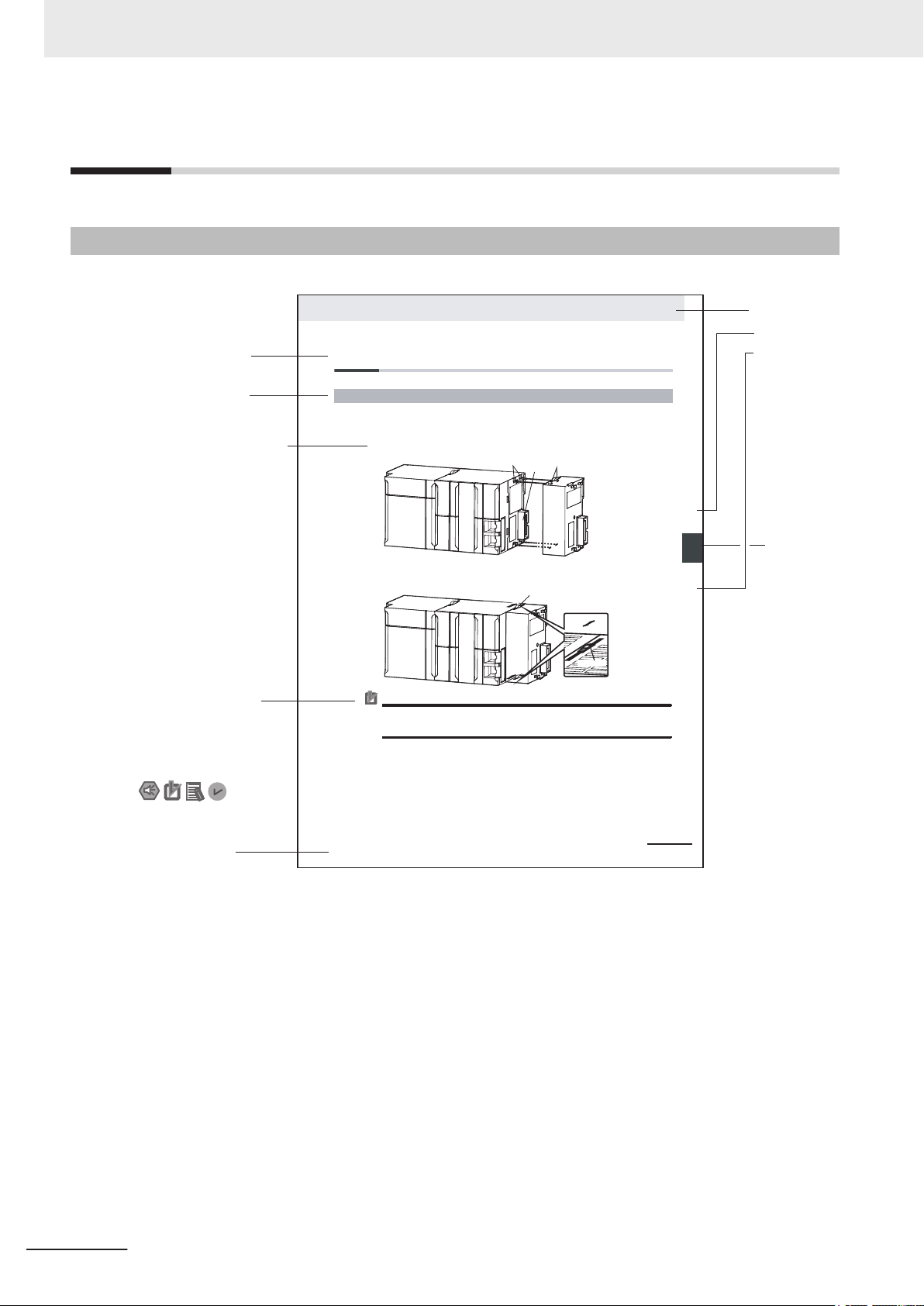
Level 1 heading
Level 2 heading
Level 3 heading
Level 2 heading
A step in a procedure
Manual name
Special information
Level 3 heading
Page tab
Gives the current
headings.
Indicates a procedure.
Icons indicate
precautions, additional
information, or reference
information.
Gives the number
of the main section.
The sliders on the tops and bottoms of the Power Supply Unit, CPU Unit, I/O Units, Special I/O
Units, and CPU Bus Units must be completely locked (until they click into place) after connecting
the adjacent Unit connectors.
Manual Structure
Manual Structure
Page Structure
The following page structure is used in this manual.
Note This illustration is provided only as a sample. It may not literally appear in this manual.
4
FH Series Vision System Hardware Setup Manual (Z366-E1)
Page 7

Special Information
Special information in this manual is classified as follows:
Precautions for Safe Use
Precautions on what to do and what not to do to ensure safe usage of the product.
Precautions for Correct Use
Precautions on what to do and what not to do to ensure proper operation and performance.
Additional Information
Additional information to read as required.
This information is provided to increase understanding or make operation easier
Manual Structure
.
FH Series Vision System Hardware Setup Manual (Z366-E1)
5
Page 8

Manual Structure
6
FH Series Vision System Hardware Setup Manual (Z366-E1)
Page 9

CONTENTS
Introduction .............................................................................................................. 1
Intended Audience
Applicable Products ......................................................................................................................................... 1
Relevant Manuals..................................................................................................... 2
Manual Structure...................................................................................................... 4
Page Structure.................................................................................................................................................4
Special Information .......................................................................................................................................... 5
Terms and Conditions Agreement........................................................................ 11
Warranty, Limitations of Liability .................................................................................................................... 11
Application Considerations ............................................................................................................................12
Disclaimers ....................................................................................................................................................12
Safety Precautions................................................................................................. 14
Symbols and the Meanings for Safety Precautions Described in This Manual .............................................14
Meanings of Alert Symbols ............................................................................................................................ 14
Warning..........................................................................................................................................................15
CONTENTS
...........................................................................................................................................1
Precautions for Safe Use ...................................................................................... 16
Condition of the Fitness of OMRON Products ............................................................................................... 16
Installation Environment ................................................................................................................................16
Power Supply and Wiring ..............................................................................................................................17
Grounding ...................................................................................................................................................... 17
Others ............................................................................................................................................................ 17
Precautions for Correct Use ................................................................................. 19
Installation and Storage Sites (FH-1000/2000/3000/5000 series) ................................................................. 19
Installation and Storage Sites (FH-L series) .................................................................................................. 19
Orientation of Product....................................................................................................................................19
Ambient Temperature ....................................................................................................................................19
Noise Resistance...........................................................................................................................................20
Component Installation and Handling............................................................................................................20
Maintenance ..................................................................................................................................................20
Communications with Upper Device..............................................................................................................20
Failsafe Measures .........................................................................................................................................21
Connecting the Sensor Controller and Monitor with a Switcher and Splitter .................................................21
Regulations and Standards .................................................................................. 22
All Series........................................................................................................................................................ 22
FH-1000/2000/3000/5000 series ...................................................................................................................22
FH-L series ....................................................................................................................................................23
Related Manuals..................................................................................................... 25
Terminology............................................................................................................ 26
Revision History..................................................................................................... 31
Sections in This Manual ........................................................................................ 33
FH Series Vision System Hardware Setup Manual (Z366-E1)
7
Page 10

CONTENTS
Section 1 Confirm the Package
1-1 Sensor Controller.................................................................................................................1 - 2
1-1-1
1-1-2 FH-1£££-10/FH-2£££-10/FH-3£££-10/FH-5£££-10 Series.........................................1 - 2
1-1-3 FH-1£££-20/FH-2£££-20/FH-3£££-20/FH-5£££-20 Series.........................................1 - 3
1-1-4 FH-L£££ Series .....................................................................................................................1 - 3
1-1-5 FH-L£££-10 Series ................................................................................................................1 - 3
FH-1£££/FH-2£££/FH-3£££/FH-5£££ Series..............................................................1 - 2
1-2 Sold Separately .................................................................................................................... 1 - 5
1-2-1 Cameras and Related ...............................................................................................................1 - 5
1-2-2 Monitor ......................................................................................................................................1 - 7
1-2-3 Lighting and Lighting Controller ................................................................................................1 - 8
1-2-4 Accessories...............................................................................................................................1 - 9
1-2-5 Cable.......................................................................................................................................1 - 10
1-2-6 Software ..................................................................................................................................1 - 12
Section 2 Overview of FH series
2-1 Overview of System.............................................................................................................2 - 2
2-1-1 Basic System of Measurement .................................................................................................2 - 2
2-1-2 FH-1000/FH-2000/FH-3000/FH-5000 Series ............................................................................2 - 4
2-1-3 FH-L Series ...............................................................................................................................2 - 5
2-2 System Configuration..........................................................................................................2 - 6
2-2-1 FH-1000/2000/3000/5000 Series ..............................................................................................2 - 6
2-2-2 FH-L Series ...............................................................................................................................2 - 7
2-3 Flow of Use Procedure ........................................................................................................ 2 - 8
Section 3 Configuration
3-1 Sensor Controller.................................................................................................................3 - 3
3-1-1
3-1-2 FH-L Series .............................................................................................................................3 - 14
3-2 Camera................................................................................................................................3 - 19
3-2-1 High-speed digital CMOS Camera (FH-S camera series) ......................................................3 - 19
3-2-2 Digital CMOS Camera.............................................................................................................3 - 24
3-2-3 Digital CCD Camera: FZ-S Camera Series.............................................................................3 - 27
3-2-4 High-speed Digital CCD Camera: FZ-SH Camera Series.......................................................3 - 29
3-2-5 Small Digital CCD Cameras: FZ-S Camera Series.................................................................3 - 30
3-2-6 Intelligent Compact Digital CMOS Camera: FZ-S camera Series...........................................3 - 33
3-3 Camera Cable ..................................................................................................................... 3 - 36
3-3-1 Camera Cable and Right-angle Camera Cable ......................................................................3 - 36
3-3-2 Bend resistant Camera Cable and Bend resistant Right-angle Camera Cable ......................3 - 37
3-3-3 Long-distance Camera Cable and Long-distance Right-angle Camera Cable .......................3 - 38
3-3-4 Cable Connection Table ..........................................................................................................3 - 39
3-3-5 Cable Extension Units.............................................................................................................3 - 43
3-4 Lens.....................................................................................................................................3 - 47
3-4-1 C-mount Lens for 1/3-inch Image Sensor (SV-V Series) ........................................................3 - 47
3-4-2 C-mount Lens for 2/3-inch Image Sensor (SV-H Series) ........................................................3 - 48
3-4-3 C-mount Lens for 1-inch Image Sensor (VS-H1 Series) .........................................................3 - 49
3-4-4 C-mount Lens for 4/3-inch Image Sensor (VS-LLD Series) ....................................................3 - 50
3-4-5 M42-mount Lens for Large Image Sensor (VS-L/M42-10 Series)...........................................3 - 51
3-4-6 Lenses for Small Camera (FZ-LES Series).............................................................................3 - 51
3-4-7 Vibration and Shock Resistant C-mount Lens for 2/3-inch Image Sensor (VS-MCA Series)..3 - 52
3-4-8 Vibration and Shock Resistant C-mount Lens for 1-inch Image Sensor (VS-MCH Series) ....3 - 54
3-4-9 Vibration and Shock Resistant C-mount Lens for 1-inch Image Sensor (VS-MCH1 Series) ..3 - 57
3-4-10 Vibration and Shock Resistant M42-mount Lens for 1.8-inch Image Sensor (VS-MCL/
FH-1000/2000/3000/5000 Series ..............................................................................................3 - 3
M42-10 Series)........................................................................................................................3 - 60
8
FH Series Vision System Hardware Setup Manual (Z366-E1)
Page 11

CONTENTS
3-4-11 High-resolution
TCH Series) ............................................................................................................................3 - 62
3-4-12 High-resolution Telecentric Lens for C-mount Lens for 1.1-inch Image Sensor (VS-TEV
Series).....................................................................................................................................3 - 64
3-4-13 Extension Tubes......................................................................................................................3 - 65
3-4-14 Meaning of Optical Chart ........................................................................................................3 - 66
Telecentric Lens for C-mount Lens for 2/3-inch Image Sensor (VS-
3-5 Touch Panel Monitor and Cable .......................................................................................3 - 82
3-6 LCD and Cable ...................................................................................................................3 - 88
3-7 Sysmac Studio ...................................................................................................................3 - 91
Section 4 Handling and Installation Environment
4-1 All Series...............................................................................................................................4 - 2
4-2
FH-1000/2000/3000 Series ...................................................................................................4 - 4
4-3 FH-L Series ........................................................................................................................... 4 - 5
Section 5 Setup and Wiring
5-1 When turning ON and OFF..................................................................................................5 - 2
5-1-1
5-1-2 FH-1000/2000/3000/5000 Series ..............................................................................................5 - 3
5-1-3 FH-L Series ...............................................................................................................................5 - 3
5-2 Fail-Safe Measures ..............................................................................................................5 - 4
5-3 Sensor Controller Installation.............................................................................................5 - 5
5-3-1 All Series ...................................................................................................................................5 - 5
5-3-2 FH-1000/2000/3000/5000 Series ..............................................................................................5 - 5
5-3-3 FH-L Series .............................................................................................................................5 - 11
5-4 Setup Touch Panel Monitor or Monitor ............................................................................5 - 20
5-4-1 All Series .................................................................................................................................5 - 20
5-4-2 FH-1000/2000/3000/5000 Series ............................................................................................5 - 20
5-4-3 FH-L Series .............................................................................................................................5 - 20
5-5 Camera Installation............................................................................................................5 - 22
5-5-1 All Series .................................................................................................................................5 - 22
5-5-2 FH-1000/2000/3000/5000 Series ............................................................................................5 - 23
5-5-3 FH-L Series .............................................................................................................................5 - 24
5-6 Insert/Remove SD Memory Card or USB memory .......................................................... 5 - 25
5-6-1 Common in all series...............................................................................................................5 - 25
5-7 Use by Connecting Software ............................................................................................5 - 26
5-7-1 Sysmac Studio FH Tool ...........................................................................................................5 - 26
5-7-2 FZ_FH Remote Operation Tool ...............................................................................................5 - 26
5-7-3 Simulation Software ................................................................................................................5 - 26
5-8 Installation in a Control Panel ..........................................................................................5 - 27
5-8-1 All Series .................................................................................................................................5 - 27
5-8-2 FH-1000/2000/3000/5000 Series ............................................................................................5 - 29
5-8-3 FH-L Series .............................................................................................................................5 - 31
All Series ...................................................................................................................................5 - 2
Section 6 I/O Interface
6-1 Parallel Interface ..................................................................................................................6 - 2
6-1-1 All Series ...................................................................................................................................6 - 2
6-1-2 FH-1000/2000/3000/5000 Series ..............................................................................................6 - 3
6-1-3 FH-L Series .............................................................................................................................6 - 12
6-1-4 Other (Parallel Converter Cable).............................................................................................6 - 18
FH Series Vision System Hardware Setup Manual (Z366-E1)
9
Page 12

CONTENTS
6-2 Encoder Interface...............................................................................................................6 - 29
6-3 EtherCAT Interface.............................................................................................................6 - 32
6-4 Ethernet Interface ..............................................................................................................6 - 34
6-5 Serial Interface ...................................................................................................................6 - 38
Index
6-2-1
6-3-1 FH-1000/2000/3000/5000 Series ............................................................................................6 - 32
6-4-1 FH-1000/2000/3000/5000 Series ............................................................................................6 - 34
6-4-2 FH-L Series .............................................................................................................................6 - 36
6-5-1 All Series .................................................................................................................................6 - 38
FH-1000/2000/3000/5000 Series ............................................................................................6 - 29
10
FH Series Vision System Hardware Setup Manual (Z366-E1)
Page 13

Terms and Conditions Agreement
Terms and Conditions Agreement
Warranty, Limitations of Liability
Warranties
Exclusive Warranty
l
Omron’s exclusive warranty is that the Products will be free from defects in materials and work-
manship for a period of twelve months from the date of sale by Omron (or such other period ex-
pressed in writing by Omron). Omron disclaims all other warranties, express or implied.
Limitations
l
OMRON MAKES NO WARRANTY OR REPRESENTATION, EXPRESS OR IMPLIED, ABOUT
NON-INFRINGEMENT, MERCHANTABILITY OR FITNESS FOR A PARTICULAR PURPOSE OF
THE PRODUCTS. BUYER ACKNOWLEDGES THAT IT ALONE HAS DETERMINED THAT THE
PRODUCTS WILL SUITABLY MEET THE REQUIREMENTS OF THEIR INTENDED USE.
Omron further disclaims all warranties and responsibility of any type for claims or expenses based
on infringement by the Products or otherwise of any intellectual property right.
Buyer Remedy
l
Omron’s sole obligation hereunder shall be, at Omron’s election, to (i) replace (in the form originally
shipped with Buyer responsible for labor charges for removal or replacement thereof) the non-com-
plying Product, (ii) repair the non-complying Product, or (iii) repay or credit Buyer an amount equal
to the purchase price of the non-complying Product; provided that in no event shall Omron be re-
sponsible for warranty, repair, indemnity or any other claims or expenses regarding the Products
unless Omron’s analysis confirms that the Products were properly handled, stored, installed and
maintained and not subject to contamination, abuse, misuse or inappropriate modification. Return
of any Products by Buyer must be approved in writing by Omron before shipment. Omron Compa-
nies shall not be liable for the suitability or unsuitability or the results from the use of Products in
combination with any electrical or electronic components, circuits, system assemblies or any other
materials or substances or environments. Any advice, recommendations or information given orally
or in writing, are not to be construed as an amendment or addition to the above warranty.
See http://www.omron.com/global/ or contact your Omron representative for published information.
Limitation on Liability; Etc
OMRON COMPANIES SHALL NOT BE LIABLE FOR SPECIAL, INDIRECT, INCIDENTAL, OR CON-
SEQUENTIAL DAMAGES, LOSS OF PROFITS OR PRODUCTION OR COMMERCIAL LOSS IN ANY
FH Series Vision System Hardware Setup Manual (Z366-E1)
11
Page 14

Terms and Conditions Agreement
WAY CONNECTED WITH THE PRODUCTS, WHETHER SUCH CLAIM IS BASED IN CONTRACT,
W
ARRANTY, NEGLIGENCE OR STRICT LIABILITY.
Further, in no event shall liability of Omron Companies exceed the individual price of the Product on
which liability is asserted.
Application Considerations
Suitability of Use
Omron Companies shall not be responsible for conformity with any standards, codes or regulations
which apply to the combination of the Product in the Buyer
er’s request, Omron will provide applicable third party certification documents identifying ratings and
limitations of use which apply to the Product. This information by itself is not sufficient for a complete
determination of the suitability of the Product in combination with the end product, machine, system, or
other application or use. Buyer shall be solely responsible for determining appropriateness of the par-
ticular Product with respect to Buyer’s application, product or system. Buyer shall take application re-
sponsibility in all cases.
’s application or use of the Product. At Buy-
NEVER USE THE PRODUCT FOR AN APPLICATION INVOLVING SERIOUS RISK TO LIFE OR
PROPERTY OR IN LARGE QUANTITIES WITHOUT ENSURING THAT THE SYSTEM AS A WHOLE
HAS BEEN DESIGNED TO ADDRESS THE RISKS, AND THAT THE OMRON PRODUCT(S) IS
PROPERLY RATED AND INSTALLED FOR THE INTENDED USE WITHIN THE OVERALL EQUIP-
MENT OR SYSTEM.
Programmable Products
Omron Companies shall not be responsible for the user’s programming of a programmable Product, or
any consequence thereof.
Disclaimers
Performance Data
Data presented in Omron Company websites, catalogs and other materials is provided as a guide for
the user in determining suitability and does not constitute a warranty
Omron’s test conditions, and the user must correlate it to actual application requirements. Actual per-
formance is subject to the Omron’s Warranty and Limitations of Liability.
. It may represent the result of
12
Change in Specifications
Product specifications and accessories may be changed at any time based on improvements and oth-
er reasons. It is our practice to change part numbers when published ratings or features are changed,
or when significant construction changes are made. However
FH Series Vision System Hardware Setup Manual (Z366-E1)
, some specifications of the Product may
Page 15

Terms and Conditions Agreement
be changed without any notice. When in doubt, special part numbers may be assigned to fix or estab-
lish key specifications for your application. Please consult with your Omron’
time to confirm actual specifications of purchased Product.
s representative at any
Errors and Omissions
Information presented by Omron Companies has been checked and is believed to be accurate; how-
ever
, no responsibility is assumed for clerical, typographical or proofreading errors or omissions.
FH Series Vision System Hardware Setup Manual (Z366-E1)
13
Page 16
Safety Precautions
Safety Precautions
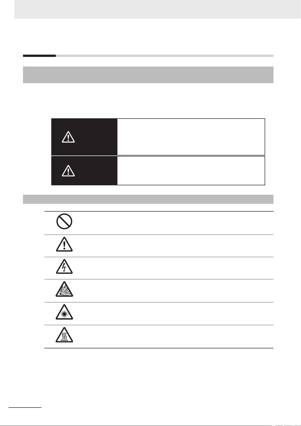
Symbols and the Meanings for Safety Precautions Described in This Manual
The following notation is used in this manual to provide precautions required to ensure safe usage of a
Sensor Controller. The safety precautions that are provided are extremely important to safety.
Always read and heed the information provided in all safety precautions.
The following notation is used.
Indicates a potentially hazardous situation which, if not avoid-
WARNING
ed, will result in minor or moderate injury
ous injury or death.
Additionally there may be significant property damage.
, or may result in seri-
Caution
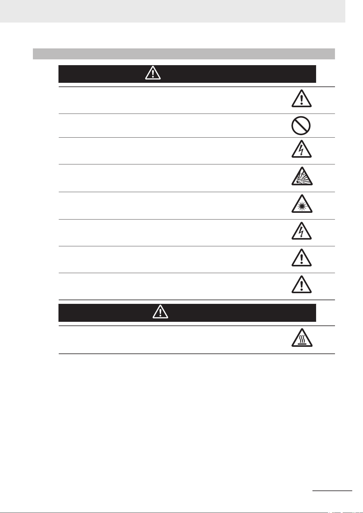
Meanings of Alert Symbols
General Prohibition
Indicates general prohibitions, including warnings, for which there is no specific
symbol
General Caution
Indicates general cautions, including warnings, for which there is no specific symbol.
Electrical Hazard
Indicates the possible danger of electric shock under specific conditions.
Explosion Hazard
Indicates the possible danger of explosion under specific conditions.
LED light Hazard
Indicates the possible danger of LED radiation or light.
Indicates a potentially hazardous situation which, if not avoid-
ed, may result in minor or moderate injury or in property dam-
age.
14
High Temperature Caution
Indicates the possible danger of injury by high temperature under specific conditions.
FH Series Vision System Hardware Setup Manual (Z366-E1)
Page 17
Warning
This product must be used according to this manual and Instruction Sheet. Failure to observe this may result in the impairment of functions and performance of the product.
This product is not designed or rated for ensuring the safety of persons. Do not use it for
such purposes.
Never connect the AC power supply with this product. When the AC power supply is connected, it causes the electric shock and a fire.
A lithium battery is built into the Controller and may occasionally combust, explode, or burn if
not treated properly. Dispose of the Controller as industrial waste, and never disassemble,
apply pressure that would deform, heat to 100°C or higher, or incinerate the Controller.
Safety Precautions
WARNING
If you keep watching the LED light, it may have an adverse effect on the eyes, do not stare
directly into the light emitted from the LED. If a specular object is used, take care not to allow
reflected light to enter your eyes.
Do not touch the terminals while the power supply is ON. Doing so may result in electrical
shock.
Please take external safety measures so that the system as a whole should be on the safe
side even if a failure of a Sensor Controller or an error due to an external factor occurred. An
abnormal operation may result in serious accident.
Please take fail-safe measures on your side in preparation for an abnormal signal due to signal conductor disconnection and/or momentary power interruption.
An abnormal operation may result in a serious accident.
Caution
Please take fail-safe measures on your side in preparation for an abnormal signal due to signal conductor disconnection and/or momentary power interruption. An abnormal operation
may result in a serious accident.
FH Series Vision System Hardware Setup Manual (Z366-E1)
15
Page 18

Precautions for Safe Use
Precautions for Safe Use
Condition of the Fitness of OMRON Products
• Please do not use this product to directly or indirectly use to detect the human body for the purpose
of ensuring the safety. In the same application, please use the safety sensor that is published on our
sensor catalog.
• Omron products are designed and manufactured as general-purpose products for use in general in-
dustrial applications. They are not intended to be used in the following critical applications. If you are
using Omron products in the following applications, Omron shall not provide any warranty for such
Omron products, unless otherwise specifically agreed or unless the specific applications are intend-
ed by Omron.
a) Applications with stringent safety requirements, including but not limited to nuclear power control
equipment, combustion equipment, aerospace equipment, railway equipment, elevator/lift equip-
ment, amusement park equipment, medical equipment, safety devices and other applications
that could cause danger/harm to people's body and life.
b) Applications that require high reliability, including but not limited to supply systems for gas, water
and electricity, etc., 24 hour continuous operating systems, financial settlement systems and oth-
er applications that handle rights and property.
c) Applications under severe condition or in severe environment, including but not limited to out-
door equipment, equipment exposed to chemical contamination, equipment exposed to electro-
magnetic interference and equipment exposed to vibration and shocks.
d) Applications under conditions and environment not described in specifications.
(1) In addition to the applications listed from (a) to (d) above, Omron products (see definition) are not
intended for use in vehicles designed human transport (including two wheel vehicles). Please do
NOT use Omron products for vehicles designed human transport. Please contact the Omron
sales staff for information on our automotive line of products.
(2) The above is part of the Terms and Conditions Agreement. Please use carefully read the contents
of the guarantee and disclaimers described in our latest version of the catalog, data sheets and
manuals.
Installation Environment
• Do not use the product in the environment with flammable or explosive gases.
• Install the product so that the air can flow freely through its cooling vents.
• Regularly clean the vent holes or fan outlet to prevent dust or particles blocking them. Internal tem-
perature increases when those are blocked, it causes malfunction.
• To secure safety for operation and maintenance, install the product apart from high-voltage devices
and power devices.
• Make sure to tighten all screws in mounting.
• When mounting the product using DIN rail mounting brackets, be sure to tighten all screws.
• Make sure to mount the product on DIN-rail securely.
16
FH Series Vision System Hardware Setup Manual (Z366-E1)
Page 19

Power Supply and Wiring
• Make sure to use the product within the power voltage specified by catalog, this manual, or instruc-
tion sheet.
Never connect the product to AC power. If connected, it causes malfunction.
•
• Select and use the appropriate wire size based on consumption current.
• Keep the power supply wires as short as possible.
• Provide the power from a DC power supply (safety extra-low voltage circuits) that has been taken
measures not to generate high-voltage.
• Check the following again before turning on the power.
- Is the voltage and polarity of the power supply correct? (24 VDC)
- Is not the load of the output signal short-circuited?
- Is the load current of the output signal appropriate?
- Is not the mistake found in wiring?
- Is the voltage and polarity of the encoder power (ENC0_VDD/GND ENC1_VDD/GND) supply?
(5VDC)
• The recommended power supply for FH-L series is the S8VS-£££24 (manufactured by OMRON)
or S8VK-G-£££24 (manufactured by OMRON).
Precautions for Safe Use
Grounding
• Since the power supply circuit for the Sensor Controller is described in the manual and instruction
sheet, please check it.
When a base is packed in a camera that will be connected to the Sensor Controller, make sure to
•
mount the camera using the base. Since the enclosure of the camera body is connected to the inter-
nal circuits, the circuits may cause short-circuit with FG if the base is not used to mount the camera
and result in malfunction or damage.
• Apply Class D grounding (grounding resistance: 100 [Ω] or less) Wire the grounding wire for the
Sensor Controller independently. If the grounding wire is shared with other devices or connected to
a building beam, the Sensor Controller may be adversely affected.
• Check the wiring again before turning on the power.
• Do not ground the plus (+) terminal when the FH series Sensor Controller is connected to the FH-
SC12/FH-SM12. The internal circuits may cause a short-circuit and result in malfunction.
• Do not ground the plus (+) terminal of the 24 VDC power source when the FH series Sensor Con-
troller is connected to the FH-MT12 with a USB cable. The internal circuits may cause a short-circuit
and result in malfunction.
• When using the Sensor Controller and the peripheral devices such as a monitor, USB connection
devices, RS-232C connection devices, there should be no potential difference in ground level. If not,
it may cause malfunction. Take measures that the potential difference does not occur between the
grounds for the Sensor Controller and the peripheral devices.
Others
• Use only the camera and cables designed specifically for the product. Use of other products may
result in malfunction or damage of the product.
Always turn OFF the power of the Sensor Controller and peripheral devices before connecting or
•
disconnecting a camera or cable. Connecting the cable with power supplied may result in damage of
the camera or peripheral devices.
FH Series Vision System Hardware Setup Manual (Z366-E1)
17
Page 20

Precautions for Safe Use
• For the cable that is flexed repeatedly, use the robotic cable type (Bend resistant camera cable) to
prevent damages.
•
Do not apply torsion stress to the cable. It may damage the cable.
• Secure the minimum bending radius of the cable. Otherwise the cable may be damaged.
• Do not apply stress to the connector by pulling or bending the cable. It may damage the connector.
• Do not attempt to dismantle, repair, or modify the product.
• Should you notice any abnormalities, immediately stop use, turn OFF the power supply, and contact
your OMRON representative.
• While the power is ON or immediately after the power is turned OFF, the Sensor Controller and
camera case are still hot. Do not touch the case.
• When disposing of the product, treat it as an industrial waste.
• Do not drop the product nor apply excessive vibration or shock to the product. Doing so may cause
malfunction or burning.
• This product is heavy. Be careful not to drop it while handling.
• A lithium battery is incorporated, so a severe injury may rarely occur due to ignition or explosion.
• Be sure to take fail-safe measures externally when controlling stages and robots by using the meas-
urement results of the Sensor Controller (axis movement output by calibration and alignment meas-
urement).
18
FH Series Vision System Hardware Setup Manual (Z366-E1)
Page 21

Precautions for Correct Use
Precautions for Correct Use
Installation and Storage Sites (FH-1000/2000/3000/5000 series)
Install and store the product in a location that meets the following conditions:
• Surrounding temperature of 0 to +50°C*1 (-20 to +65°C in storage)
*1. FH-5000 Series: Surrounding temperature of 0 to 45°C
• No rapid changes in temperature (place where dew does not form)
• Relative humidity of between 35 to 85%
• No presence of corrosive or flammable gases
• Place free of dust, salts and iron particles
• Place free of vibration and shock
• Place out of direct sunlight
• Place where it will not come into contact with water, oils or chemicals
• Place not affected by strong electro-magnetic waves
• Place not near to high-voltage, or high-power equipment
Installation and Storage Sites (FH-L series)
Install and store the product in a location that meets the following conditions:
•
Surrounding temperature of 0 to +55°C (-25 to +70°C in storage)
• No rapid changes in temperature (place where dew does not form)
• Relative humidity of between 10 to 90%
• No presence of corrosive or flammable gases
• Place free of dust, salts and iron particles
• Place free of vibration and shock
• Place out of direct sunlight
• Place where it will not come into contact with water, oils or chemicals
• Place not affected by strong electro-magnetic waves
• Place not near to high-voltage, or high-power equipment
Orientation of Product
• For efficient heat dissipation, install the product only with the orientation written in this manual or the
Instruction Sheet. Install the product so that the air can flow freely through its cooling vents.
Ambient Temperature
• To secure good ventilation, install the product with clearance written in this manual or the Instruction
Sheet.
Do not install the product immediately above significant heat sources, such as heaters, transform-
•
ers, or large-capacity resistors.
• Use the product within the operating temperature range based on the specifications of it.
• Install a forced cooling fan or air conditioner not to exceed the operating temperature range when
the ambient temperature is close to the upper limit of its range.
FH Series Vision System Hardware Setup Manual (Z366-E1)
19
Page 22

Precautions for Correct Use
Noise Resistance
• Do not install the Sensor Controller in a cabinet with high-voltage equipment installed.
Mount the Sensor Controller at 200 [mm] or more from power cables apart.
•
Component Installation and Handling
• Touching Signal Lines:
When touching a terminal part or a signal wire in a connector
strap or another device to prevent damage from static electricity.
• Handling a USB Memory/SD memory card: (Refer to Using External Storage Device in the Vision
System FH/FHV Series User’s Manual (Cat. No. Z365).
Do not insert an SD memory card in the reverse orientation, at an angle, or in a twisting manner.
Before removing a USB memory device, make sure that data is not being read or written to them.
Before removing a SD memory card, make sure that data is not being read or written to them.
For a USB memory device, the memory device's LED flashes or lights while data is being read or
written, so make sure that it is turned OFF before removing the memory.
For SD memory card, the SD BUSY LED flashes or lights while data is being read or written, so
make sure that it is turned OFF before removing the memory.
• Turning OFF the Power:
When a message is displayed indicating that a task is in progress, do not turn OFF the power. Doing
so causes the data in the memory to be corrupted, resulting in the product not operating properly
upon the next start-up.
Do not turn OFF during saving data to Sensor Controller.
When turns OFF, conform the followings proceedings have completed. and then operate again.
- When saves using Sensor Controller: Confirm the save processing is completed and next opera-
tion is possible.
- When saves using communication command: Intended command is completed. BUSY signal is
turned OFF.
• Setting of Power Source:
The power source need to be supplied from DC power source apparatus which is taken a save ultra-
low voltage circuit: to protect high voltage.
, take anti-static measures using a wrist
Maintenance
• Turn OFF the power and ensure the safety before maintenance.
Clean the lens with a lens-cleaning cloth or air brush.
•
• Lightly wipe off dirt with a soft cloth.
• Dirt on the image element must be removed using an air brush.
• Do not use thinners or benzine.
• To secure safety for operation and maintenance, install the product apart from high-voltage devices
and power devices.
Communications with Upper Device
• After confirming that the product is started up, communicate with the high-order device. Since uncer-
tain signals may be output from the high-order interface at the product start-up, take measures such
as clearing the reception buf
20
fer of your device at the initial stage.
FH Series Vision System Hardware Setup Manual (Z366-E1)
Page 23

Precautions for Correct Use
Failsafe Measures
• Be sure to take fail-safe measures externally when controlling stages and robots by using the meas-
urement results of the Sensor Controller (axis movement output by calibration and alignment meas-
urement).
On a Sensor Controller side, supplementary use operations and branches of the Sensor Controller
•
to configure a check flow such as “data should not be externally provide if the data is in a range from
-XXXXX to XXXXX” based on the stage/robots range of movement.
Connecting the Sensor Controller and Monitor with a Switcher and Splitter
• Do not use devices that may require re-recognition of the monitor by the Sensor Controller when a
switching operation was performed. If such re-recognition processing happens at switching opera-
tion, it may cause measurement time to be longer
.
FH Series Vision System Hardware Setup Manual (Z366-E1)
21
Page 24
Regulations and Standards
Regulations and Standards
All Series
Using Product Outside Japan
If you export (or provide a non-resident with) this product or a part of this product that falls under the
category of goods (or technologies) specified by the Foreign Exchange and Foreign Trade Control
Law as those which require permission or approval for export, you must obtain permission or approval
or service transaction permission) pursuant to the law.
U.S. California Notice:
This product contains a lithium battery for which the following notice applies: Perchlorate Material -
special handling may apply.
See "www.dtsc.ca.gov/hazardouswaste/perchlorate".
Conformance to KC Standards
Observe the following precaution if you use this product in Korea.
• Guidance for users
This product meets the electromagnetic compatibility requirements for business use. There is a risk
of radio interference when this product is used in home.
WEEE Directive
Dispose of in accordance with WEEE Directive
FH-1000/2000/3000/5000 series
Conformance to EC/EU Directives
The product is compliant with the standards below:
22
FH Series Vision System Hardware Setup Manual (Z366-E1)
Page 25

Regulations and Standards
• EC Directive 2004/108/EC (Until April 19 2016) / EU Directive 2014/30/EU (After April 20 2016)
EN61326-1 Electromagnetic environment: Industrial electromagnetic environment (EN/IEC 61326-1
T
able 2)
• Also, the following condition is applied to the immunity test of this product.
- If the level of disturbance of the video is such that characters on the monitor are readable, the test
is a pass.
• This product complies with EC/EU Directives. EMC-related performance of the OMRON devices that
comply with EC/EU Directives will vary depending on the configuration, wiring, and other conditions
of the equipment or control panel on which the OMRON devices are installed.
• The customer must, therefore, perform the final check to confirm that devices and the overall ma-
chine conform to EMC standards.
• If there is a need to respond to the EC / EU directive, please use by an analog RGB output.
Conformance to UL Standards (FH-1000/FH-3000 series)
This product complies with UL Standards.
•
UL508
Conformance to UL Standards (FH-2000/FH-5000 series)
This product complies with UL Standards.
•
UL61010-2-201
FH-L series
Conformance to EC/EU Directives
The product is compliant with the standards below:
•
EC Directive 2004/108/EC (Until April 19 2016) / EU Directive 2014/30/EU (After April 20 2016)
EN61326-1 Electromagnetic environment: Industrial electromagnetic environment (EN/IEC 61326-1
Table 2)
• Also, the following condition is applied to the immunity test of this product.
- If the level of disturbance of the video is such that characters on the monitor are readable, the test
is a pass.
• This product complies with EC/EU Directives. EMC-related performance of the OMRON devices that
comply with EC/EU Directives will vary depending on the configuration, wiring, and other conditions
of the equipment or control panel on which the OMRON devices are installed.
• The customer must, therefore, perform the final check to confirm that devices and the overall ma-
chine conform to EMC standards.
• If there is a need to respond to the EC / EU directive, please use by an analog RGB output.
Conformance to UL Standards
This product complies with UL Standards.
FH Series Vision System Hardware Setup Manual (Z366-E1)
23
Page 26

Regulations and Standards
• UL61010-2-201
24
FH Series Vision System Hardware Setup Manual (Z366-E1)
Page 27

Related Manuals
The followings are the manuals related to this manual. Use these manuals for reference.
Name of Manual Cat. No.. Model Purpose Contents
Vision System
FH Instruction Sheet
Vision System
FH Instruction Sheet
Vision System
FH-L Instruction Sheet
Vision System
FH/FHV Series
User's Manual
Vision System
FH/FHV series
Processing Item Function
Reference Manual
Vision System
FH/FHV Series
User's manual for Communications Settings
Vision System
FH series
Hardware Setup Manual
Vision System
FH series
Macro Customize Functions Programming Manual
Vision System
FH Series
Operation Manual
for Sysmac Studio
9608337-2
3102269-4
9606631-1
Z365
Z341 When User confirm
Z342 When User confirm
Z366
Z367 When User operate
Z343
FH-1£££
FH-1£££-££
FH-3£££
FH-3£££-££
FH-2£££
FH-2£££-££
FH-5£££
FH-5£££-££
FH-L£££
FH-L£££-££
FH-1£££
FH-1£££-££
FH-2£££
FH-2£££-££
FH-3£££
FH-3£££-££
FH-5£££
FH-5£££-££
FH-L£££
FH-L£££-££
FH-1£££
FH-1£££-££
FH-2£££
FH-2£££-££
FH-3£££
FH-3£££-££
FH-5£££
FH-5£££-££
FH-L£££
FH-L£££-££
FH-1£££
FH-1£££-££
FH-2£££
FH-2£££-££
FH-3£££
FH-3£££-££
FH-5£££
FH-5£££-££
To confirm the safety
and usage precautions of the V
System FH series
Sensor Controller.
To confirm the safety
and usage precautions of the V
System FH series
Sensor Controller.
To confirm the safety
and usage precautions of the V
System FH-Lite series Sensor Controller.
When User want to
know about the
FH/FHV series.
the details of each
processing items at
the create the measurement flow or operate it.
the setting of communication functions.
When User want to
know about the
Hard-ware specifications or to setup the
Sensor Controller of
the V
FH series.
or programming using Macro Customize
functions.
When User connect
to NJ/NX series via
EtherCA
cation.
ision
ision
ision
ision System
T communi-
Describes the definitions of basic
terms, meaning of signal words, and
precautions for correct use of FH
series in the manual.
To confirm the safety and usage precautions of the Vision System FH
series Sensor Controller.
Describes the definitions of basic
terms, meaning of signal words, and
precautions for correct use of FH-L
series in the manual.
Describes the soft functions, setup,
and operations to use FH/FHV series/
Describes the software functions,
settings, and operations for using
FH/FHV series.
Describes the functions, settings,
and communications methods for
communication between FH/FHV
series and PLCs.
The following communications protocol are described.
Parallel, PLC Link, EtherNet/IP
EtherCAT, and Non-procedure.
Describes FH series specifications,
dimensions, part names, I/O information, installation information, and
wiring information.
Describes the functions, settings,
and operations for using Macro Customize function of the FH series.
Describes the operating procedures
for setting up and operating FH series Vision Sensors from the Sysmac
Studio FH Tools.
Related Manuals
,
FH Series Vision System Hardware Setup Manual (Z366-E1)
25
Page 28

Terminology
Terminology
Term Definition
FH Series All FH series model names as follows:
FH-1000 series
FH-2000 series
FH-3000 series
FH-5000 series
FH-L series
FHV Series All FHV series model names.
FZ5 series All FZ series name shows the following:
FZ5-600 series
FZ5-800 series
FZ5-1100 series
FZ5-1200 series
FZ5-L series
Sensor Controller It is a generic name of FH/FZ5 series. For FHV series, it has the same meaning as
Measurement flow (abbreviated as flow)
Measurement processing Executing processing items for inspections and measurements.
Measurement ID Information of time when the sensor controller receives the measurement trigger
FH-1£££, FH-1£££-££, FH-2£££, FH-2£££-££, FH-3£££, FH-3£££££, FH-5£££, FH-5£££-££, FH-L£££, FH-L£££-££
All FH-1£££
FH-1£££, FH-1£££-££
All FH-2£££
FH-2£££, FH-2£££-££
All FH-3£££
FH-3£££, FH-3£££-££
All FH-5£££
FH-5£££, FH-5£££-££
All FH-L£££
FH-L£££, FH-L£££-££
FZ5-6££, FZ5-6££-££, FZ5-8££, FZ5-8££-££, FZ5-1
£, FZ5-12££, FZ5-12££-££, FZ5-L35£, FZ5-L35£-££
All FZ5-6££ series name the following:
FZ5-6££, FZ5-6££-££
All FZ5-8££ series name the following:
FZ5-8££, FZ5-8££-££
All FZ5-11££ series name the following:
1££, FZ5-11££-££
FZ5-1
All FZ5-12££
FZ5-12££, FZ5-12££-££
All FZ5-L35£
FZ5-L35£, FZ5-L35£-££
Smart Camera.
A continuous flow of measurement processing. A measurement flow consists of a
scene created from a combination of processing items.
and the line no.
Format of measurement ID: YYYY
(YYYY: Year, MM: Month, DD: Date, HH: Hour, MM: Minute, SS: Second, XXXX:
Millisecond and Line number.)
series model names as follows:
series model names as follows:
series model names as follows:
series model names as follows:
series model names as follows:
1££, FZ5-11££-£
series name the following:
series name the following:
-MM-DD_HH-MM-SS-XXXX
• Example:
Measurement time: 11:10:25.500 AM, December 24, 2007 and Line 0, the measurement ID is "2007-12-24_11-10-25-5000".
26
FH Series Vision System Hardware Setup Manual (Z366-E1)
Page 29

Terminology
Term Definition
Processing item Any of the individual items for vision inspections that are partitioned and packaged
so that they can be flexibly combined.
These include the Search, Position Compensation, and Fine Matching items.
Processing items can be classified for image input ([Input image]), inspection/
measurement ([Measurement]), image correction ([Compensate image]), inspection/measurement support ([Support measurement]), process branching ([Branch]),
results external output ([Output result]), resulting image display ([Display result]),
etc.
ou can freely classify processing items to handle a wide range of applications.
Y
A scene (i.e., a unit for changing the measurement flow) is created by registering
the processing items as units.
Scene A unit for changing the measurement flow that consists of a combination of proc-
essing items.
Scene is used because of the correspondence to the scene (i.e., type of measurement object and inspection contents) where measurements are performed.
A scene is created for each measurement or measurement contents.
ou can easily achieve a changeover simply by changing the scene when the
Y
measurement
object or inspection content changes.
Normally you can set up to 128 scenes. If you need more than 128 scenes, you
can separate them into different groups or use the Conversion Scene Group Data
Tool to create a scene group that contains over 128 scenes.
Processing unit (abbreviated as unit)
Measurement trigger A trigger for executing measurements.
Test measurement A measurement that is performed to manually test (check) measurements under
Single measurement A measurement that is executed only once in synchronization with the trigger input.
Continuous measurement Measurements are executed repeatedly and automatically without a trigger input.
A processing item that is registered in a scene.
Numbers are assigned to processing units in order from the top and they are executed in that order
Processing items are registered for the processing units to create a scene (i.e., a
unit for changing the measurement flow).
With a parallel interface, the STEP signal is used. With a serial interface, an Execute One Measurement or a Start Continuous Measurement command is used.
the conditions that are set in the currently displayed scene.
est measurements can be executed on an Adjustment Window. Processing is
T
completed inside the Controller and the measurement results are not normally output on an external interface.
However, you can select Output in Test measurement to output the measurement
results after executing measurements.
.
FH Series Vision System Hardware Setup Manual (Z366-E1)
27
Page 30

Terminology
Operation mode
Parallel processing (an
option for any of the
above operation modes)
Multi-input function A function that is used to consecutively and quickly input images.
Term Definition
• Double Speed Multi-input:
A mode that processes the measurement flow for the first trigger and then processes the measurement flow in parallel for the second trigger to achieve a highspeed trigger input interval. It is used together with the multi-input function.
• Multi-line Random-trigger:
A trigger mode that allows you to independently processing multiple measurement flows.
With traditional image processing, two or more triggers cannot be acknowledged
at the same time. In Multi-line Random-trigger Mode, you can randomly input
multiple triggers into one Controller to independently process multiple scenes in
parallel.
• Non-stop adjustment mode:
A mode that allows you to adjust the flow and set parameters while performing
measurements.
The enables adjustments without stopping the line or stopping inspections.
• Standard:
A logging mode that allows complete parallel processing of measurements and
logging.
raditionally, logging was not possible while processing measurements. Either
T
measurements or logging had to be given priority and the other one had to wait.
With this mode, you can save the measurement images in external storage without affecting the transaction time.
Parallel processing splits part of the measurement flow into two or more tasks, and
processes each task in parallel to shorten the transaction time.
Processing items for parallel processing are used so that the user can specify the
required parallel processing.
It allows the next STEP signal to be acknowledged as soon as the image input
processing is completed. There is no need to wait for measurement processing to
be completed.
ou can check whether image input processing has been completed with the status
Y
of the READY signal. Even if the READY signal is ON when measurement processing is being executed, the next STEP signal can be acknowledged.
28
FH Series Vision System Hardware Setup Manual (Z366-E1)
Page 31

When position of object to be measured is deflected
When position deflection correction is set in advance:
Object to be measured
overflows Measurement area.
Reference position
Measurement area and objects to be measured
are correctly aligned.
Object to be measured
Measurement area
Measurement will be carried out
after measured object enters into Measurement area.
Measurement will be carried out after
moving the Measurement area for a
corresponding deflection.
Measurement will be carried out
after moving the image for a
corresponding deflection and
returning to the reference position.
Terminology
Term Definition
Position compensation When the location and direction of measured objects are not fixed, the positional
deviation between reference position and current position is calculated and measurement is performed after correcting.
Please select processing items that are appropriate to the measurement object
from processing items that are related to position compensation.
Reference position The point that is always the reference. If the location of the registered model is dif-
Model The image pattern that serves as the inspection target. Characteristics portions are
ferent from the reference position, the setting should be changed in Ref. setting.
extracted from images of the object and registered as model registration.
FH Series Vision System Hardware Setup Manual (Z366-E1)
29
Page 32

−“1” expresses with 2’s Complement (for 8 bits)
00000000 (= 0)
-)
(In the case of 1, minus 1)
00000001 (= 1)
11111111 (=-1)
00000001 (= 1)
11111110
11111111 (=-1)
Invert all bits
Plus 1
11111111 (= -1)
00001001 (= 9)
+)00001010 (= 10)
Terminology
2's complement Binary numbers are generally used to represent negative numbers.
Term Definition
Negative numbers are expressed by Inverting all bits of a positive number and
adding 1 to the result.
Ex. -1 is expressed as 2's complement.
-1 can be calculated by 0-1.
There are methods for simple calculation without performing this kind of computation.
For instance, Negative number = inverting all bits of a positive number and then
adding 1 to the result.
The first digit is used to judge whether the number is positive or negative.
• When 0: Positive number (or 0)
• When 1: Negative number
The advantage of two's complement numbers is that positive and negative numbers can be used as is in calculations.
Ex. When -1+10=9
30
FH Series Vision System Hardware Setup Manual (Z366-E1)
Page 33

Revision History
Revision code
Cat. No. Z366-E1-07
A manual revision code appears as a suffix to the catalog number on the front and back covers of the
manual.
Rev. Code Rev. Date Revision Contents
01 Apr. 2016 Original product
02 Aug. 2016 Corrected mistakes
03 Apr. 2017 Corrected mistakes and revisions for the support of NY series
04 Apr. 2017 Corrected mistakes
05 June 2017 Revisions for the support of FZ5-800 Series, FZ5-1200 Series,
06 July 2018
07 July 2019 Removed FZ5 series, adjusted the layout, and corrected mistakes
Revision History
and FZ-S£5M3
Added FH-2000 series, FH-5000 series, and FH-S£21R/FH-S
£X12
FH Series Vision System Hardware Setup Manual (Z366-E1)
31
Page 34

Revision History
32
FH Series Vision System Hardware Setup Manual (Z366-E1)
Page 35

Sections in This Manual
1
2
3
4
5
1
2
3
4
5
Confirm the Package
Overview of FH series
Configuration
Handling and Installation Environment
Setup and Wiring
I
6
I
6
I
I/O Interface
Index
I
Sections in This Manual
FH Series Vision System Hardware Setup Manual (Z366-E1)
33
Page 36

Sections in This Manual
34
FH Series Vision System Hardware Setup Manual (Z366-E1)
Page 37

Confirm the Package
1-1 Sensor Controller......................................................................................... 1 - 2
1-1-1
1-1-2 FH-1£££-10/FH-2£££-10/FH-3£££-10/FH-5£££-10 Series ............ 1 - 2
1-1-3 FH-1£££-20/FH-2£££-20/FH-3£££-20/FH-5£££-20 Series ............ 1 - 3
1-1-4 FH-L£££ Series ......................................................................................... 1 - 3
1-1-5 FH-L£££-10 Series.................................................................................... 1 - 3
1-2 Sold Separately ............................................................................................1 - 5
1-2-1 Cameras and Related................................................................................... 1 - 5
1-2-2 Monitor.......................................................................................................... 1 - 7
1-2-3 Lighting and Lighting Controller .................................................................... 1 - 8
1-2-4 Accessories .................................................................................................. 1 - 9
1-2-5 Cable .......................................................................................................... 1 - 10
1-2-6 Software...................................................................................................... 1 - 12
FH-1£££/FH-2£££/FH-3£££/FH-5£££ Series ................................. 1 - 2
1
1
FH Series Vision System Hardware Setup Manual (Z366-E1)
1 - 1
Page 38

1 Confirm the Package
1-1
1-1-1
Sensor Controller
First, please check to see whether the package has all the necessary Sensor Controller parts.
FH-1£££/FH-2£££/FH-3£££/FH-5£££ Series
• Sensor Controller: 1
FH-1£££/FH-2£££/FH-3£££/FH-5£££: 1
•
Instruction sheet: 1
• Instruction Installation Manual for FH series: 1
• General Compliance Information and Instructions for EU: 1
• Membership registration: 1
• Power source: 1 (male)
FH-XCN: 1
• Ferrite core for camera cable: 2
1-1-2
FH-1£££-10/FH-2£££-10/FH-3£££-10/FH-5£££-10 Series
• Sensor Controller: 1
FH-1£££-10/FH-2£££-10/FH-3£££-10/FH-5£££-10: 1
Instruction sheet: 1
•
• Instruction Installation Manual for FH series: 1
• General Compliance Information and Instructions for EU: 1
• Membership registration: 1
• Power source: 1 (male)
FH-XCN: 1
• Ferrite core for camera cable: 4
1 - 2
FH Series Vision System Hardware Setup Manual (Z366-E1)
Page 39

1-1-3
1 Confirm the Package
1-1 Sensor Controller
FH-1£££-20/FH-2£££-20/FH-3£££-20/FH-5£££-20 Series
1
1-1-4
• Sensor Controller: 1
FH-1£££-20/FH-2£££-20/FH-3£££-20/FH-5£££-20: 1
Instruction sheet: 1
•
• Instruction Installation Manual for FH series: 1
• General Compliance Information and Instructions for EU: 1
• Membership registration: 1
• Power source: 1 (male)
FH-XCN: 1
• Ferrite core for camera cable: 8
FH-L£££ Series
• Sensor Controller: 1
FH-L£££: 1
•
Instruction sheet: 1
• Instruction Installation Manual for FH-L series: 1
• General Compliance Information and Instructions for EU: 1
• Membership registration: 1
• Power source: 1 (male)
FH-XCN-L: 1
1-1-3 FH-1£££-20/FH-2£££-20/FH-3£££-20/FH-5£££-20 Series
1-1-5
FH Series Vision System Hardware Setup Manual (Z366-E1)
FH-L£££-10 Series
• Sensor Controller: 1
FH-L£££-10: 1
1 - 3
Page 40

1 Confirm the Package
• Instruction sheet: 1
•
Instruction Installation Manual for FH-L series: 1
• General Compliance Information and Instructions for EU: 1
• Membership registration: 1
• Power source: 1 (male)
FH-XCN-L: 1
1 - 4
FH Series Vision System Hardware Setup Manual (Z366-E1)
Page 41

1-2
1 Confirm the Package
1-2 Sold Separately
Sold Separately
1-2-1
Cameras and Related
Camera
Appear-
ance
High-speed Digital CMOS
Cameras
(Lens required)
High-speed Digital CMOS
Cameras
(Lens required)
High-speed Digital CMOS
Cameras
(Lens required)
Type Description
Color/
Mono-
chrome
12 megapixels
(Up to four cameras can be connected to one
Controller
era on page
1 - 5)
5 megapixels Color
0.4 megapixels Color
12 megapixels
(Up to four cameras can be connected to one
Controller
4 megapixels Color
2 megapixels Color
0.3 megapixe Color 3.3 ms FH-SC
. Cam-
. *4)
Color
Monochrome
Monochrome
Monochrome
Color
Monochrome
Monochrome
Monochrome
Monochrome
Image Ac-
quisition
*1
T
ime
24.9 ms
10.3 ms
1.9 ms
25.7 ms
8.5 ms
4.6 ms
*2
*2
*3
*2
*2
*2
FH-SCX12
FH-SMX12
FH-SCX05
FH-SMX05
FH-SCX
FH-SMX
FH-SC12
FH-SM12
FH-SC04
FH-SM04
FH-SC02
FH-SM02
FH-SM
1
1-2-1 Cameras and Related
Model
FH Series Vision System Hardware Setup Manual (Z366-E1)
1 - 5
Page 42

1 Confirm the Package
Appear-
ance
Type Description
Digital CMOS Cameras
(Lens required)
20.4 megapixels
(Up to four cameras can be con-
Color/
Mono-
chrome
Color
Monochrome
Image Ac-
quisition
*1
T
ime
42.6 ms
*2
Model
FH-SC21R
FH-SM21R
nected to one
Controller. Cam-
era on page
1 - 5)
5 megapixels Color 71.7 ms FH-SC05R
Mono-
FH-SM05R
chrome
5 megapixels Color 38.2 ms FZ-SC5M3
Mono-
FZ-S5M3
chrome
Digital CCD Cameras
(Lens required)
2 megapixels Color 33.3 ms FZ-SC2M
Mono-
FZ-S2M
chrome
0.3 megapixels Color 12.5 ms FZ-SC
Mono-
FZ-S
chrome
High-speed Digital CCD Cameras
(Lens required)
Small Digital CCD Cameras
(Lenses for small camera required)
0.3 megapixels Color 4.9 ms FZ-SHC
Mono-
FZ-SH
chrome
0.3 megapixels
flat type
Color 12.5 ms FZ-SFC
Mono-
FZ-SF
chrome
0.3 megapixels
pen type
Color 12.5 ms FZ-SPC
Mono-
FZ-SP
chrome
Intelligent Compact Digital
CMOS Cameras
Narrow view Color 16.7 ms FZ-SQ010F
Standard view Color FZ-SQ050F
(Camera + Manual Focus Lens
+ High power Lighting)
Wide View (long-
Color FZ-SQ100F
distance)
Wide View (short-
Color FZ-SQ100N
distance)
*1. The image acquisition time does not include image conversion processing time by the Sensor Controller.
*2. Frame rate in high speed mode when the camera is connected using two camera cables. For other condi-
tions, please refer to 3-2-1
High-speed digital CMOS Camera (FH-S camera series) on page 3 - 19.
*3. The value in high speed mode. For other information, refer to 3-2-1 High-speed digital CMOS Camera (FH-
S camera series) on page 3 - 19.
*4. Up to eight cameras other than 12 megapixels cameras can be connected to a FH-5050-20, FH-3050-20,
FH-2050-20, or FH-1050-20.
1 - 6
FH Series Vision System Hardware Setup Manual (Z366-E1)
Page 43

Camera Mounting Bracket
1 Confirm the Package
1-2 Sold Separately
Appear-
ance
-
For Intelligent Compact Digital Camera
Mounting Base for FZ-S£, FH-S£05R, FH-S£X
Mounting Base for FZ-S£2M
Mounting Base for FZ-SH£
Mounting Base for FH-S£, FZ-S£5M£, FH-S£X05, FH-S£02, FH-S£04,
FH-S£X12, FH-S£21R
Mounting Base for FH-S£12
M42 - F Mount Conversion Adapter FH-ADF/M42-10
Description Model
Mounting Bracket FQ-XL
Precise Mounting Brackets FQ-XL2
Polarizing Filter Attachment
(Packaged item)
FQ-XF1
FZ-S-XLC
FZ-S2M-XLC
FZ-SH-XLC
FH-SM-XLC
FH-SM12-XLC
Camera Cable
Appear-
ance
Camera Cable
Cable length: 2 m, 3 m, 5 m, or 10 m
Bend resistant Camera Cable
Cable length: 2 m, 3 m, 5 m, or 10 m
Right-angle Camera Cable
Cable length: 2 m, 3 m, 5 m, or 10 m
Bend resistant Right-angle Camera Cable
Cable length: 2 m, 3 m, 5 m, or 10 m
Long-distance Camera Cable
Cable length: 15 m
Long-distance Right-angle Camera Cable
Cable length: 15 m
Cable Extension Unit
Up to two Extension Units and three Cables can be connected
(Maximum cable length: 45 m *2)
*1.
Insert the cables length into £ in the model number as follows. 2 m = 2, 3 m = 3, 5 m = 5, 10 m = 10
*2. The maximum cable length depends on the Camera being connected, and the model and length of the Ca-
ble being used. For further information, please refer to 3-3-4 Cable Connection T
3-3-5 Cable Extension Units on page 3 - 43.
When a high-speed digital CMOS camera FH-S£02/-S£04/-S£12 is used in the high speed digital mode of
transmission speed, two camera cables are required.
*3. This Cable has an L-shaped connector on the Camera end.
*2
*2
*3
Description
*2
*2
*2
*3
*2
*3
FZ-V3 £M
FZ-VSB3 £M
FZ-VSL3 £M
FZ-VSLB3 £M
FZ-VS4 15M
FZ-VSL4 15M
FZ-VSJ
able on page 3 - 39 and
Model
*1
1
1-2-2 Monitor
1-2-2
FH Series Vision System Hardware Setup Manual (Z366-E1)
Monitor
1 - 7
Page 44

1 Confirm the Package
Touch Panel Monitor and Cables
Appear-
ance
Touch Panel Monitor 12.1 inches (for FH Sensor Controllers)
*1. FH Series Sensor Controllers version 5.32 or higher is required.
Appear-
ance
DVI-Analog Conversion Cable for Touch Panel Monitor
Cable length: 2 m, 5 m or 10 m
RS-232C Cable for Touch Panel Monitor
Cable length: 2 m, 5 m or 10 m
USB Cable for Touch Panel Monitor
Cable length: 2 m or 5 m
*1.
Insert the cables length into £ in the model number as follows. 2 m = 2, 5 m = 5, 10 m = 10
*2.
Insert the cables length into £££ in the model number as follows. 2 m = 200, 5 m = 500, 10 m = 010.
Description Model
*1
Description Model
LCD Monitor and Cable
Appear-
ance
LCD Monitor 8.4 inches for Box-type Controllers
Description Model
*1
FH-MT12
FH-VMDA £M
XW2Z-££
£PP-1
FH-VUAB £M
FZ-M08
*2
*1
*1
1-2-3
LCD Monitor Cable
When you connect a LCD Monitor FZ-M08 to FH sensor controller
it in combination with a DVI-I -RGB Conversion Connector FH-VMRGB.
DVI-I -RGB Conversion Connector FH-VMRGB
*1. It can be used in FH series.
, please use
FZ-VM 2M
FZ-VM 5M
Lighting and Lighting Controller
Appear-
ance
-
External Lighting - FLV Series
Lighting Controller (Required to
control external
lighting from a
Controller)
For FLV-Series Camera Mount Lighting Controller FLV-TCC Series
For FL-Series Camera Mount Lighting Controller FL-TCC Series
For the method of setting the lighting controller, please refer to the respective instruction manual.
Description Model
- FL Series
Analog Lighting Controller FLV-ATC Series
1 - 8
FH Series Vision System Hardware Setup Manual (Z366-E1)
Page 45

1 Confirm the Package
1-2-4
Accessories
Appear-
ance
USB Memory 2 GB FZ-MEM2G
SD card 2 GB HMC-SD291
USB/Monitor Switcher FZ-DU
-
- Calibration Plate FZD-CAL
Mouse - Driverless wired mouse
(A mouse that requires the mouse driver to be installed is not supported.)
EtherCAT junction
slaves
Industrial Switching
Hubs for EtherNet/IP
and Ethernet
Common items related
to DIN rail (for FHL550/-L550-10)
Description Model
8 GB FZ-MEM8G
4 GB HMC-SD491
-
3 ports Power supply voltage:
20.4 VDC to 28.8 VDC
6 ports GX-JC06
3 ports Failure detection: None Current
5 ports Failure detection: None W4S1-05B
DIN rail mounting bracket FH-XDM-L
(24 VDC -15 % to +20
%)
Failure detection: Supported
Current
consumption: 0.22
A
consumption: 0.22
A
GX-JC03
W4S1-03B
W4S1-05C
1-2 Sold Separately
1
1-2-4 Accessories
DIN 35
mm rail
• Length:
75.5/95.5/1
cm
15.5/200
• Height: 7.5 mm
• Material: Iron
• Surface: Conductive
• Length:
75.5/95.5/1
cm
15.5/200
• Height: 15 mm
• Material: Iron
• Surface: Conductive
End plate Need 2 pieces each
Sensor Controller
PHOENIX
CONTACT
PHOENIX
ACT
CONT
NS 35/7.5 PERF
NS 35/15 PERF
CLIPFIX 35
FH Series Vision System Hardware Setup Manual (Z366-E1)
1 - 9
Page 46

1 Confirm the Package
1-2-5
Cable
Parallel I/O Cables and Encoder Cable
Appear-
ance
Parallel I/O Cable
Cable length: 2 m, 5 m or 15 m
Parallel I/O Cable for Connector-terminal Conversion Unit
Cable length: 0.5 m, 1 m, 1.5 m, 2 m, 3 m, 5 m
Connector-Terminal Block Conversion Units, General-purpose devices
Encoder Cable for line-driver
Cable length: 1.5 m
*1. 2 Cables are required for all I/O signals.
*2.
Insert the cables length into £ in the model number as follows. 2 m = 2, 5 m = 5, 15 m = 15
*3.
Insert the cables length into £££ in the model number as follows. 0.5 m = 050, 1 m = 100, 1.5 m = 150, 2
m = 200, 3 m = 300, 5 m = 500
*4.
Insert the wiring method into £ in the model number as follows. Phillips screw = J, Slotted screw (rise up) =
E, Push-in spring = P
Refer to the XW2R Series catalog (Cat. No. G077) for details.
*1
Description Model
XW2Z-S013-£
*1
XW2Z-£££EE
*3
XW2R-£34GD-T
*4
FH-VR 1.5M
*2
Recommended EtherCAT and EtherNet/IP Communications Cables
Use Straight STP (shielded twisted-pair) cable of category 5 or higher with double shielding (braiding
and aluminum foil tape) for EtherCA
Use Straight or cross STP (shielded twisted-pair) cable of category 5 or higher for EtherNet/IP.
Appear-
ance
For Ether-
T
CA
Cable with Standard type Connectors on Both Ends (RJ45/
RJ45)
• Wire Gauge and Number of Pairs:
AWG27, 4-pair Cable
• Cable Sheath material:
LSZH
• Cable color:
Blue, Yellow, or Green
• Cables length:
0.2 m, 0.3 m, 0.5 m, 1 m, 1.5 m, 2 m, 3 m, 5 m, 7.5 m, 10 m,
15 m, 20 m
Cable with Rugged type Connectors on Both Ends (RJ45/RJ45)
• Wire Gauge and Number of Pairs:
A
WG22, 2-pair Cable
• Cables length:
0.3 m, 0.5 m, 1 m, 2 m, 3 m, 5 m, 10 m, 15 m
T.
Description Model
XS6W-6LSZH8S
S£CM-Y
*1
XS5W-T421£MD-K
1 - 10
FH Series Vision System Hardware Setup Manual (Z366-E1)
Page 47

1 Confirm the Package
Appear-
ance
Cable with Rugged type Connectors on Both Ends (M12/RJ45)
• Wire Gauge and Number of Pairs:
WG22, 2-pair Cable
A
Description Model
XS5W-T421£MC-K
• Cables length:
0.3 m, 0.5 m, 1 m, 2 m, 3 m, 5 m, 10 m, 15 m
Cable with Rugged type Connectors on Both Ends (M12 L/RJ45)
• Wire Gauge and Number of Pairs:
WG22, 2-pair Cable
A
XS5W-T422£MC-K
• Cables length:
0.3 m, 0.5 m, 1 m, 2 m, 3 m, 5 m, 10 m, 15 m
For Ether-
-
CAT and
EtherNet/I
-
P
-
-
-
-
-
-
-
For EtherNet/IP
-
*1. The lineup features Low Smoke Zero Halogen cables for in-cabinet use and PUR cables for out-of-cabinet
use.
*2. We recommend you to use above cable for EtherCAT and EtherNet/IP, and RJ45 Connector together.
*3. We recommend you to use above cable for EtherCAT and EtherNet/IP, and RJ45 Assembly Connector to-
gether
.
*4. We recommend you to use above cable for EtherNet/IP and RJ45 Connectors together.
Wire
Gauge and
Number of
Pairs:
AWG24, 4pair Cable
Wire
Gauge and
Number of
Pairs:
A
WG22, 2-
pair Cable
Wire
Gauge and
Number of
Pairs:
0.5mm x
4P
Cables Hitachi Metals, Ltd. NETSTAR-C5E
SAB 0.5 x 4P CP
*2
*2
*2
*2
*2
RJ45 Con-
Kuramo Electric Co.
SWCC Showa Cable Systems Co.
JMACS Japan Co.,Ltd.
Panduit Corporation
KETH-SB
FAE-5004
IETP-SB
MPS588-C
nectors
Cables Kuramo Electric Co. KETH-PSB-OMR
*3
*3
*3
RJ45 As-
JMACS Japan Co.,Ltd.
SWCC Showa Cable Systems Co.
PNET/B
FAE-5002
OMRON XS6G-T421-1
sembly
Connector
Cables Fujikura Ltd. F-LINK-E 0.5mm
*4
x 4P
RJ45 Con-
Panduit Corporation
MPS588
*4
nectors
1-2 Sold Separately
1
1-2-5 Cable
Precautions for Correct Use
Please be careful while cable processing, for EtherCAT, connectors on both ends should be
shield connected and for EtherNet/IP
FH Series Vision System Hardware Setup Manual (Z366-E1)
, connectors on only one end should be shield connected.
1 - 11
Page 48

1 Confirm the Package
1-2-6
Software
Specifications
Product
Sysmac Studio Standard
Edition
er.1. ££
V
The Sysmac Studio is the software that
provides an integrated environment for
setting, programming, debugging and
maintenance of machine automation
controllers including CPU units of NJ/NX
Series and industrial PCs of NY Series,
EtherCat Slave, and the HMI.
Sysmac Studio runs on the following
OS.
Number of
licenses
- (Media
only)
1 license - SYSMAC-SE201L
3 license - SYSMAC-SE203L
10 license - SYSMAC-SE210L
30 license - SYSMAC-SE230L
50 license - SYSMAC-SE250L
DVD
Media
*1
SYSMAC-SE200D
• OS:
Windows 7 (32-bit/64-bit version)
/Windows 8 (32-bit/64-bit version)
/Windows 8.1 (32-bit/64-bit version)
/Windows 10 (32-bit/64-bit version)
This software also includes the function
of the Vision edition. For more details
about other compatible models and
functions, refer to our product information.
Sysmac Stu-
ision Edi-
dio V
tion
Ver.1.££
Note:
Sysmac Studio Vision Edition is a limited license that provides selected functions required for FH-series/FHV-
*2*3
series/FQ-M-series Vision Sensor settings.
1 license - SYSMAC-VE001L
• Site licenses are available for users who will run Sysmac Studio on multiple computers. Ask your OMRON
sales representative for details.
• Sysmac Studio version 1.07 or higher supports the FH Series.
Model
1 - 12
*1. The same media is used for both the Standard Edition and the Vision Edition.
*2. With the Vision Edition, you can use only the setup functions for FH-series/FHV-series/FQ-M-series Vision
Sensors.
*3. This product is a license only. You need the Sysmac Studio Standard Edition DVD media to install it.
FH Series Vision System Hardware Setup Manual (Z366-E1)
Page 49

1 Confirm the Package
Product
Application
Producer
Specifications
Software components that provide a development environment to further customize the standard controller features
of the FH Series.
System requirements:
• CPU: Intel Pentium Processor (SSE2
or higher)
• OS: Windows 7 Professional
(32/64bit) or
Enterprise (32/64bit) or Ultimate
(32/64bit),
Windows 8 Pro (32/64bit) or Enterprise (32/64bit),
Windows 8.1 Pro (32/64bit) or Enterprise (32/64bit)
Windows 10 Pro (32/64bit) or Enterprise (32/64bit)
• .NET Framework: .NET Framework
3.5 SP1 or higher
• Memory: At least 2 GB RAM
vailable disk space: At least 2 GB
A
• Browser: Microsoft
6.0 or later
®
Internet Explorer
• Display: XGA (1024 x 768), True Col-
or (32-bit) or higher
• Optical drive: CD/DVD drive
• The following software is required to
customize the software:
Microsoft® Visual Studio® 2010 Professional or
Microsoft® Visual Studio® 2008 Professional or
Microsoft® Visual Studio® 2012 Professional
Number of
licenses
- (Media
only)
1 license - FH-AP1L
Media
CD-ROM FH-AP1
1-2 Sold Separately
Model
1
1-2-6 Software
FH Series Vision System Hardware Setup Manual (Z366-E1)
1 - 13
Page 50

1 Confirm the Package
1 - 14
FH Series Vision System Hardware Setup Manual (Z366-E1)
Page 51

2
2
Overview of FH series
2-1 Overview of System .....................................................................................2 - 2
2-1-1
2-1-2 FH-1000/FH-2000/FH-3000/FH-5000 Series................................................ 2 - 4
2-1-3 FH-L Series................................................................................................... 2 - 5
2-2 System Configuration.................................................................................. 2 - 6
2-2-1 FH-1000/2000/3000/5000 Series.................................................................. 2 - 6
2-2-2 FH-L Series................................................................................................... 2 - 7
2-3 Flow of Use Procedure ................................................................................2 - 8
Basic System of Measurement ..................................................................... 2 - 2
FH Series Vision System Hardware Setup Manual (Z366-E1)
2 - 1
Page 52

2 Overview of FH series
2-1
2-1-1
Overview of System
Basic System of Measurement
An FH series Sensor Controller uses pre-built packages that contain all the processing tasks (for im-
age input, measurement processing, displays, outputs, etc.) that are required for vision inspections.
You arrange these packaged processes in order of execution of the vision inspection.
An FH series Sensor Controller executes vision inspections according to user-created flows.
Additional Information
In the FH series Sensor Controller, a flow that contains packaged processes that are arranged
in order of execution of processing items and image processing is called a measurement flow.
Processing items and measurement flows can have more than one setting. You can switch the
setting based on the scene to inspect. (Refer to the Vision System FH/FHV series User's
Manual (Cat. No. Z365).)
2 - 2
FH Series Vision System Hardware Setup Manual (Z366-E1)
Page 53

Image Input
Defect
Search
Measurement flow
FH
Output Unit
Camera
PLC or other external device
The measurement flow is executed basically in
order of the unit numbers.
Measurement
trigger
• Judgement
result
• Measured
values
Image input
from the
Camera
Measurement
processing of
the input image
Measurement
results are
output.
2 Overview of FH series
Concept of Measurement Processing
When the FH receives a measurement trigger from the PLC or other external device, the image input
from a Camera, measurement processing, and output of measurement results (e.g., OK/NG judge-
ment results) are executed in the order that those processing items are registered in the measurement
flow
.
2-1 Overview of System
2
2-1-1 Basic System of Measurement
In the measurement flow, you can change the processing to execute based on the inspection results
or input conditions of the vision inspection.
ou can use macro processing to execute pre-packaged processing items and functions in the FH to
Y
create original programs. This allows you to create original measurement processes, display process-
ing, input and output processing, and settings dialog boxes that are custom-tailored to your applica-
tion.
FH Series Vision System Hardware Setup Manual (Z366-E1)
2 - 3
Page 54

Sysmac Studio
Standard Edition
Vision Edition
EtherCAT Cables
*1
EtherCAT junction slaves
Ethernet Cables
*2
Vision System
FH Sensor Controllers
Cameras
special cable for cameras
Another slave
(With built-in EtherCAT slave function)
EtherCAT Cables
*1
NJ/NX/NY-series
Controller
Incremental
rotary encoder
special cable
special cable for Touch Panel Monitor
cable tor Touch Panel interface
special cable for I/O
Touch Panel Monitor
FH-MT12
PLC for
I/O control
Trigger input
sensor
Lighting
Controllers
Lighting
Controllers
External
Lightings
2 Overview of FH series
2-1-2
FH-1000/FH-2000/FH-3000/FH-5000 Series
Vision System FH-1000/2000/3000/5000 series is the BOX type Sensor Controller having functions
and high-speed needed to incorporate with a machine, and safety
, reliability, and maintainability as an
industrial controller.
This series includes the conventional image processing functions and added functions needed to in-
corporate with a machine. As Sensor Controller supporting high-speed communications, with Ether-
CAT, it enables synchronous control with connecting to input and output devices such and a program-
mable controller.
This series can connect with up to eight cameras and transmits images faster than that in the conven-
tional models.
OMRON provides Sysmac device designed by unified communication specifications and User Inter-
face Specifications. Vision System FH-1000/2000/3000/5000 series can be easily connected with
NJ/NX/NY-series Controller and Sysmac devices such as EtherCAT slaves by using the automation
software Sysmac Studio and which are designed to meet the optimum functions and operations.
The example of a system configuration is shown below.
EtherCAT Connection for FH Series
Example of the FH Sensor Controllers (4-camera type)
2 - 4
*1. To use STP (shielded twisted-pair) cable of category 5 or higher with double shielding (braiding
and aluminum foil tape) for EtherCA
*2. To use STP (shielded twisted-pair) cable of category 5 or higher for Ethernet and RJ45 connector.
T and RJ45 connector.
FH Series Vision System Hardware Setup Manual (Z366-E1)
Page 55

cable tor Touch Panel
interface
Touch Panel Monitor
FH-MT12
special cable for
Touch Panel Monitor
PLC for I/O control
Personal
computer
Lighting
Controllers
External
Lightings
Cameras
Ethernet Cables
*1
special cable for
cameras
special cable for I/O
PLC for
I/O control
Vision System
FH-L Sensor Controller
Industrial Switching Hubs for
EtherNet/IP and Ethernet
Trigger input
sensor
Lighting
Controllers
2 Overview of FH series
2-1-3
FH-L Series
Vision System FH-L series is the small and low-cost BOX type Sensor Controller having functions and
high-speed needed to built into a machine, and safety
controller.
This series can connect with up to four cameras and transmits images faster than that in the conven-
tional models.
, reliability, and maintainability as an industrial
2-1 Overview of System
2
2-1-3 FH-L Series
*1. To use STP (shielded twisted-pair) cable of category 5 or higher for Ethernet and RJ45 connector.
FH Series Vision System Hardware Setup Manual (Z366-E1)
2 - 5
Page 56

Standalone camera
FZ-SC/FZ-S/
FZ-SC2M/FZ-S2M/
FZ-SFC/FZ-SF/
FZ-SPC/FZ-SP/
FZ-SHC/FZ-SH
FH-SC/FH-SM
FH-SC02/FH-SM02
Intelligent Compact Digital Camera
FZ-SQ010F/FZ-SQ050F/
FZ-SQ100F/FZ-SQ100N
FH-SC21R and FH-SM21R are only available in
FH-2000/5000 series.
FLV-TCC1/FLV-TCC4/
FLV-TCC1EP/FLV-TCC3HB
* USB memory
FZ-MEM2G
FZ-MEM8G
* Switcher
In case of switching multiple of sensor
controllers with a single monitor or touch
panel monitor, please make sure to use an
appropriate product.
Recommended model by OMRON: FZ-DU
* SD Memory Card
HMC-SD291
HMC-SD491
Detects workpieces as images.
The Controller performs the image processing specified
by the user settings and outputs the measurement results.
Use the monitor to check images and
display the condition-setting menus.
Use the monitor to check images and
display the condition-setting menus.
FH-VMDA
(2 m, 5 m, 10 m, min.
bending radius 36 mm)
FH-VMDA
(2 m, 5 m, 10 m, min. bending
radius 36 mm)
FH-VUAB
(USB type, 2 m, 5 m, min.
bending radius: 25 mm)
XW2Z-PP-1
(RS-232C type, 2 m, 5 m, 10 m,
min. bending radius: 59 mm)
The power supply connected to FH
Sensor Controller varies depending
on the number of connected cameras
and types for various consumption
current types. Use is accordingly.
Recommended Model by OMRON:
S8VK-G series/S8VS series
*
* Items indicated with an asterisk are dedicated items, and cannot be substituted.
*
*
*
**
**
*
Sensor controller
Camera cable
Camera
Power Supply
Peripheral Device
Camera with Lighting
LCD monitor
Monitor cable
Touch panel monitor
Monitor cable
Touch panel cable
Input Device
Camera 4ch type
FH-5050-10
FH-3050-10
FH-2050-10
FH-1050-10
Camera 8ch type
FH5050-20
FH3050-20
FH-2050-20
FH-1050-20
Camera 2ch type
FH-5050
FH-3050
FH-2050
FH-1050
FZ-M08 (8.4 inch) FH-MT12 (12.1 inch)
Mouse, track ball
(Commercially available USB devices)
Camera cable
FZ-VS3 (2 m, 3 m, 5 m, 10 m, min. bending radius: 69 mm)
Bend resistant camera cable
FZ-VSB3 (2 m, 3 m, 5 m, 10 m, min. bending radius: 69 mm)
Right-angle camera cable
FZ-VSL3 (2 m, 3 m, 5 m, 10 m, min. bending radius: 69 mm)
Bend resistant Right-angle camera cable
FZ-VSLB3 (2 m, 3 m, 5 m, 10 m, min. bending radius: 69 mm)
Long-distance camera cable
FZ-VS4 (15 m, min. bending radius: 78 mm)
Long-distance Right-angle camera cable
FZ-VSL4 (15 m, min. bending radius: 78 mm)
* FH-1050 and FH-3050: Only 1 Ethernet port supported
FH-SC04/FH-SM04
FZ-SC5M
/FZ-S5M
FH-SC12/FH-SM12
FH-SC05R/FH-SM05R
FH-SCX/FH-SMX
FH-SCX05/FH-SMX05
FH-SCX12/FH-SMX12
FH-SC21R/FH-SM21R
2 Overview of FH series
2-2
2-2-1
System Configuration
FH-1000/2000/3000/5000 Series
2 - 6
FH Series Vision System Hardware Setup Manual (Z366-E1)
Page 57

* Items indicated with an asterisk are dedicated items, and cannot be substituted.
The Controller performs the image processing specified
by the user settings and outputs the measurement results.
Sensor controller
Camera 2ch type
FH-L550
Camera 4ch type
FH-L550-10
*
**
**
*
Camera cable
FZ-VS3 (2 m, 3 m, 5 m, 10 m, min. bending radius: 69 mm)
Bend resistant camera cable
FZ-VSB3 (2 m, 3 m, 5 m, 10 m, min. bending radius: 69 mm)
Right-angle camera cable
FZ-VSL3 (2 m, 3 m, 5 m, 10 m, min. bending radius: 69 mm)
Bend resistant Right-angle camera cable
FZ-VSLB3 (2 m, 3 m, 5 m, 10 m, min. bending radius: 69 mm)
Long-distance camera cable
FZ-VS4 (15 m, min. bending radius: 78 mm)
Long-distance Right-angle camera cable
FZ-VSL4 (15 m, min. bending radius: 78 mm)
*
Camera cable
*
Camera
*
Camera with Lighting
* USB memory
FZ-MEM2G
FZ-MEM8G
* Switcher
In case of switching multiple of sensor
controllers with a single monitor or touch
panel monitor, please make sure to use an
appropriate product.
Recommended model by OMRON: FZ-DU
* SD Memory Card
HMC-SD291
HMC-SD491
Peripheral Device
Standalone camera
FZ-SC/FZ-S/
FZ-SC2M/FZ-S2M/
FZ-SFC/FZ-SF/
FZ-SPC/FZ-SP/
FZ-SHC/FZ-SH
FH-SC/FH-SM
FH-SC02/FH-SM02
Intelligent Compact Digital Camera
FZ-SQ010F/FZ-SQ050F/
FZ-SQ100F/FZ-SQ100N
Detects workpieces as images.
FLV-TCC1/FLV-TCC4/
FLV-TCC1EP/FLV-TCC3HB
Use the monitor to check images and
display the condition-setting menus.
Use the monitor to check images and
display the condition-setting menus.
LCD monitor Touch panel monitor
FZ-M08 (8.4 inch) FH-MT12 (12.1 inch)
FH-VMDA
(2 m, 5 m, 10 m, min.
bending radius 36 mm)
FH-VMDA
(2 m, 5 m, 10 m, min. bending
radius 36 mm)
FH-VUAB
(USB type, 2 m, 5 m, min.
bending radius: 25 mm)
XW2Z-PP-1
(RS-232C type, 2 m, 5 m, 10 m,
min. bending radius: 59 mm)
Monitor cable Monitor cable
Touch panel cable
The power supply connected to FH
Sensor Controller varies depending
on the number of connected cameras
and types for various consumption
current types. Use is accordingly.
Recommended Model by OMRON:
S8VK-G series/S8VS series
Power Supply
Input Device
Mouse, track ball
(Commercially available USB devices)
FH-SC04/FH-SM04
FZ-SC5M
/FZ-S5M
FH-SC12/FH-SM12
FH-SC05R/FH-SM05R
FH-SCX/FH-SMX
FH-SCX05/FH-SMX05
FH-SCX12/FH-SMX12
FH-SC21R/FH-SM21R
2 Overview of FH series
2-2-2
FH-L Series
2-2 System Configuration
2
2-2-2 FH-L Series
FH Series Vision System Hardware Setup Manual (Z366-E1)
2 - 7
Page 58

2 Overview of FH series
2-3
Flow of Use Procedure
The following table shows the flow for using the FH.
Procedure Description Reference
Preparations Installation and Wiring Section 4 Handling and Installation Envi-
4 - 1
↓
Turning ON Power 5-1 When turning ON and OFF on page
↓
Language Selection in Dialog Box (only
when the Sensor Controller is started for
the first time)
↓
Main Window (Layout 0) Display Vision System FH/FHV series User's
↓
Camera Adjustments (Display the settings
dialog box for a Camera Image Input processing item.)
↓
Select T
under Startup setting, set the settings for
Basic, Communication, and Operation
mode.
↓
Click the Data save button, and then select
Function - System restart.
↓
Select T
set the settings for Camera,
Communication and Other.
↓
Click the Data save button. Vision System FH/FHV series User's
↓
Scene Editing In the Main Window (layout 0), edit the
measurement flow
ool - System settings, and then
ool - System settings, and then
.
• Register processing items.
• Set the properties for each processing
item.
↓
Click the Data save button. Vision System FH/FHV series User's
↓↑
ronment on page
Section 5 Setup and Wiring on page
5 - 1
5 - 2
Vision System FH/FHV series User's
Manual (Cat.No. Z365)
Manual (Cat.No. Z365)
Vision System FH/FHV series User's
Manual (Cat.No. Z365)
Vision System FH/FHV series User's
Manual (Cat.No. Z365)
Vision System FH/FHV series User's
Manual (Cat.No. Z365)
Vision System FH/FHV series User's
Manual (Cat.No. Z365)
Manual (Cat.No. Z365)
Vision System FH/FHV series User's
Manual (Cat.No. Z365)
Manual (Cat.No. Z365)
2 - 8
FH Series Vision System Hardware Setup Manual (Z366-E1)
Page 59

2 Overview of FH series
Procedure Description Reference
Testing Execute test measurements.
(In the Main Window (layout 0), click the
button.)
indow (Layout 1).
↓
Measuring (Operation)
↓
Management and
Analysis
Measure
↓
Adjust the parameters for each processing
item.
↓
Click the Data save button. Vision System FH/FHV series User's
In the Main Window (layout 0), click the
Switch layout button, and then select
Main W
↓
In the Main Window (layout 1), check the
communications with the PLC.
↓
In the Main Window (layout 1), execute
commands from the PLC, such as measurement trigger commands.
Save and analyze measurement data and
images.
Vision System FH/FHV series User's
Manual (Cat.No. Z365)
Vision System FH/FHV series Processing
Item Function Reference Manual (Cat. No.
Z341)
Manual (Cat.No. Z365)
Vision System FH/FHV series User's
Manual (Cat.No. Z365)
Vision System FH/FHV series User's Manual for Communications Settings (Cat. No.
Z342)
Vision System FH/FHV series User's Manual for Communications Settings (Cat. No.
Z342)
Vision System FH/FHV series User's Manual for Communications Settings (Cat. No.
Z342)
2-3 Flow of Use Procedure
2
FH Series Vision System Hardware Setup Manual (Z366-E1)
2 - 9
Page 60

2 Overview of FH series
2 - 10
FH Series Vision System Hardware Setup Manual (Z366-E1)
Page 61

Configuration
3-1 Sensor Controller......................................................................................... 3 - 3
3-1-1
3-1-2 FH-L Series................................................................................................. 3 - 14
3-2 Camera ........................................................................................................3 - 19
3-2-1 High-speed digital CMOS Camera (FH-S camera series) .......................... 3 - 19
3-2-2 Digital CMOS Camera ................................................................................ 3 - 24
3-2-3 Digital CCD Camera: FZ-S Camera Series ................................................ 3 - 27
3-2-4 High-speed Digital CCD Camera: FZ-SH Camera Series .......................... 3 - 29
3-2-5 Small Digital CCD Cameras: FZ-S Camera Series .................................... 3 - 30
3-2-6 Intelligent Compact Digital CMOS Camera: FZ-S camera Series .............. 3 - 33
3-3 Camera Cable .............................................................................................3 - 36
3-3-1 Camera Cable and Right-angle Camera Cable .......................................... 3 - 36
3-3-2 Bend resistant Camera Cable and Bend resistant Right-angle Cam-
3-3-3 Long-distance Camera Cable and Long-distance Right-angle Cam-
3-3-4 Cable Connection Table.............................................................................. 3 - 39
3-3-5 Cable Extension Units ................................................................................ 3 - 43
3-4 Lens............................................................................................................. 3 - 47
3-4-1 C-mount Lens for 1/3-inch Image Sensor (SV-V Series)............................ 3 - 47
3-4-2 C-mount Lens for 2/3-inch Image Sensor (SV-H Series)............................ 3 - 48
3-4-3 C-mount Lens for 1-inch Image Sensor (VS-H1 Series)............................. 3 - 49
3-4-4 C-mount Lens for 4/3-inch Image Sensor (VS-LLD Series)........................ 3 - 50
3-4-5 M42-mount Lens for Large Image Sensor (VS-L/M42-10 Series) .............. 3 - 51
3-4-6 Lenses for Small Camera (FZ-LES Series) ................................................ 3 - 51
3-4-7 Vibration and Shock Resistant C-mount Lens for 2/3-inch Image
3-4-8 Vibration and Shock Resistant C-mount Lens for 1-inch Image Sen-
3-4-9 Vibration and Shock Resistant C-mount Lens for 1-inch Image Sen-
3-4-10 Vibration and Shock Resistant M42-mount Lens for 1.8-inch Image
3-4-11 High-resolution Telecentric Lens for C-mount Lens for 2/3-inch Im-
3-4-12 High-resolution Telecentric Lens for C-mount Lens for 1.1-inch Im-
3-4-13 Extension Tubes ......................................................................................... 3 - 65
3-4-14 Meaning of Optical Chart ............................................................................ 3 - 66
FH-1000/2000/3000/5000 Series.................................................................. 3 - 3
era Cable..................................................................................................... 3 - 37
era Cable..................................................................................................... 3 - 38
Sensor (VS-MCA Series) ............................................................................ 3 - 52
sor (VS-MCH Series)................................................................................... 3 - 54
sor (VS-MCH1 Series)................................................................................. 3 - 57
Sensor (VS-MCL/M42-10 Series)................................................................ 3 - 60
age Sensor (VS-TCH Series) ...................................................................... 3 - 62
age Sensor (VS-TEV Series) ...................................................................... 3 - 64
3
3
FH Series Vision System Hardware Setup Manual (Z366-E1)
3 - 1
Page 62

3 Configuration
3-5 Touch Panel Monitor and Cable ................................................................ 3 - 82
3-6
LCD and Cable............................................................................................ 3 - 88
3-7 Sysmac Studio ........................................................................................... 3 - 91
3 - 2
FH Series Vision System Hardware Setup Manual (Z366-E1)
Page 63

3 Configuration
3-1
3-1-1
Sensor Controller
FH-1000/2000/3000/5000 Series
Specification
FH-5000/FH-2000
l
Series FH-5000 Series FH-2000 Series
Type
Model FH-5050
Controller Type Box type
Parallel IO polarity NPN/PNP (common)
Main
Functions
Operation
Mode
Parallel Processing Yes
Number of Connectable Camera
Supported Camera
Camera I/F OMRON I/F
Possible Number of
Captured Images
Possible Number of
Logging Images to
Sensor Controller
Standard Yes
Double
Speed
Multi-input
Non-stop
adjustment
mode
Multi-line
randomtrigger
mode
FH-S series camera
FZ-S series camera
High-speed, Large-capacity
Controller(4 cores)
Yes
Yes
Yes (Maximum 8 lines)
2 4 8 2 4 8
All of the FH-S series
cameras are connectable.
All of the FZ-S series cameras are connectable.
Refer to About Number of Logging Images or About Max. Number of
Loading Images during Multi-input
User's Manual (Cat.No. Z365).
FH-5050-10FH-5050-
20
*1
All of the
FH-S series cameras are
connecta-
*2
ble.
High-speed, Large-capacity
Controller(2 cores)
FH-2050
All of the FH-S series
cameras are connectable.
in the Vision System FH/FHV series
FH-2050-10FH-2050-
20
All of the
FH-S series cameras are
connecta-
*2
ble.
3-1 Sensor Controller
3
3-1-1 FH-1000/2000/3000/5000 Series
FH Series Vision System Hardware Setup Manual (Z366-E1)
3 - 3
Page 64

3 Configuration
External
Interface
Series FH-5000 Series FH-2000 Series
Type
Model FH-5050
Possible Number of
Scenes
Operating
on UI
Setup Create the processing flow using Flow editing.
Language Japanese, English, Simplified Chinese, Traditional Chinese, Korean,
Serial Communication RS-232C x 1
Ethernet
Communication
EtherNet/IP Communication
PROFINET Communication
EtherCAT Communication
Parallel I/O 12 inputs/31 outputs: Use 1 Line. Operation mode: Except Multi-line
Encoder Interface Input voltage: 5 V ± 5%
Monitor Interface DVI-I output (Analog RGB & DVI-D single link) x 1
USB I/F USB2.0 host x 2 (BUS Power: 5 V/0.5 A per port)
SD Card I/F SDHC x 1
USB
Mouse
Touch
Panel
Protocol Non-procedure (TCP/UDP)
I/F 1000BASE-T x 2
High-speed, Large-capacity
Controller(4 cores)
FH-5050-10FH-5050-
20
128
Yes (wired USB and driver is unnecessary type)
Yes (RS-232C/USB connection: FH-MT12)
German, French, Spanish, Italian, V
Yes (Target/Ethernet port)
es (Slave/Ethernet port)
• Y
• Conformance class A
Yes (slave)
random-trigger mode.
17 inputs/37 outputs: Use 2 Line. Operation mode: Multi-line randomtrigger mode.
14 inputs/29 outputs: Use 3 to 4 Line. Operation mode: Multi-line random-trigger mode.
19 inputs/34 outputs: Use 5 to 8 Line. Operation mode: Multi-line random-trigger mode.
Signal: RS-422A Line Driver Level
Phase A/B/Z: 1 MHz
USB3.0 host x 2 (BUS Power: 5 V/0.9 A per port)
High-speed, Large-capacity
Controller(2 cores)
FH-2050
ietnamese, Polish
FH-2050-10FH-2050-
20
3 - 4
FH Series Vision System Hardware Setup Manual (Z366-E1)
Page 65

Series FH-5000 Series FH-2000 Series
Type
Model FH-5050
Indicator
Lamps
Supply Voltage 20.4 VDC to 26.4 VDC
Current
consumption
Main POWER: Green
Ethernet NET RUN1: Green
SD Card SD POWER: Green
EtherCAT ECAT RUN: Green
• When connecting
an intelligent compact digital camera
High-speed, Large-capacity
Controller(4 cores)
FH-5050-10FH-5050-
ERROR: Red
RUN: Green
ACCESS: Y
LINK/ACT1: Y
NET RUN2: Green
LINK/ACT2: Yellow
SD BUSY
LINK/ACT IN: Green
LINK/ACT OUT
ECAT ERR: Red
5.6A
max.
ellow
ellow
: Yellow
: Green
7.7A
max.
• When connecting
the following lighting or lighting controllers without an
external power supply
V-TCC1
- FL
- FLV-TCC4
- FLV-TCC3HB
- FLV-TCC1EP
- FL-TCC1
• When connecting
the following lighting or lighting controllers
- FL-TCC1PS
- FL-MD£MC
Other than above 4.5A
max.
Built-in FAN Yes
Usage
Environment
Ambient temperature
range
Ambient humidity
range
Ambient atmosphere No corrosive gases
Vibration tolerance Oscillation frequency: 10 to 150 Hz, Half amplitude: 0.1 mm, Accelera-
Operating: 0°C to +45°C
Storage: -20 to +65°C (with no
icing or condensation)
Operating and storage: 35 to 85% (with no condensation)
tion: 15 m/s
Sweep time: 8 minute/count, Sweep count: 10, V
and down/front and behind/left and right
5.5A
max.
2
20
12.2A
max.
7.3A
max.
3 Configuration
High-speed, Large-capacity
Controller(2 cores)
FH-2050
4.6A
max.
3.5A
max.
Operating: 0°C to +50°C
Storage: -20 to +65°C (with no
icing or condensation)
FH-2050-10FH-2050-
20
6.6A
max.
4.3A
max.
ibration direction: up
11.2A
max.
6.3A max.
3-1 Sensor Controller
3
3-1-1 FH-1000/2000/3000/5000 Series
FH Series Vision System Hardware Setup Manual (Z366-E1)
3 - 5
Page 66

3 Configuration
External
Features
*1. According to the CPU performance, FH-2000 series is recommended to use up to two lines in this mode.
*2. When 12 megapixels/20.4 megapixels cameras: Max. 4 cameras are connectable. When use except 12
*3. Existing the third class grounding
Series FH-5000 Series FH-2000 Series
Type
Model FH-5050
Shock resistance
Noise immunity
Fast
ransient
T
Burst
High-speed, Large-capacity
Impact force: 150 m/s
est direction: up and down/front and behind/left and right
T
• DC power:
Direct infusion: 2 kV
continuation time: 15 ms/0.75 ms, Period: 300 ms, Application time:
1 min.
Controller(4 cores)
FH-5050-10FH-5050-
20
2
, Pulse rising: 5 ns, Pulse width: 50 ns, Burst
High-speed, Large-capacity
FH-2050
• I/O line:
Direct infusion: 1 kV, Pulse rising: 5 ns, Pulse width: 50 ns, Burst
continuation time: 15 ms/0.75 ms, Period: 300 ms, Application time:
1 min.
Grounding
Dimensions 190 mm x 115 mm x 182.5 mm
Weight Ap-
Degree of protection IEC60529 IP20
Case material Cover: zinc-plated steel plate, Side plate: aluminum (A6063)
megapixels/20.4 megapixels cameras: Max. 8 cameras are connectable.
Class D grounding (100 Ω or less grounding resistance)
Note Height: Including the rubber at the base.
prox.3.4k
g
Approx.3.6k
g
Approx.3.6k
g
Approx.3.4k
g
Controller(2 cores)
FH-2050-10FH-2050-
*3
Approx.3.6k
g
Approx.3.6k
g
20
FH-3000/FH-1000
l
Series FH-3000 Series FH-1000 Series
Type Standard Controller(4 cores) Standard Controller(2 cores)
Model FH-3050
Controller Type Box type
Parallel IO polarity NPN/PNP (common)
Main
Functions
Operation
Mode
Parallel Processing Yes
Standard Yes
Double
Speed
Multi-input
Non-stop
adjustment
mode
Multi-line
randomtrigger
mode
Yes
Yes
Yes (Maximum 8 lines)
FH-3050-10FH-3050-
20
*1
FH-1050
FH-1050-10FH-1050-
20
3 - 6
FH Series Vision System Hardware Setup Manual (Z366-E1)
Page 67

External
Interface
3 Configuration
Series FH-3000 Series FH-1000 Series
Type Standard Controller(4 cores) Standard Controller(2 cores)
Model FH-3050
Number of Connectable Camera
Supported Camera
Camera I/F OMRON I/F
Possible Number of
Captured Images
Possible Number of
Logging Images to
Sensor Controller
Possible Number of
Scenes
Operating
on UI
Setup Create the processing flow using Flow editing.
Language Japanese, English, Simplified Chinese, Traditional Chinese, Korean,
Serial Communication RS-232C x 1
Ethernet
Communication
EtherNet/IP Communication
PROFINET Communication
EtherCAT Communication
Parallel I/O 12 inputs/31 outputs: Use 1 Line. Operation mode: Except Multi-line
FH-S series camera
FZ-S series camera
USB
Mouse
Touch
Panel
Protocol Non-procedure (TCP/UDP)
I/F 1000BAS
2 4 8 2 4 8
FH-S series cameras
except FH-SM21R/
SC21R are connectable.
All of the FZ-S series cameras are connectable.
Refer to About Number of Logging Images
Loading Images during Multi-input in the Vision System FH/FHV series
User's Manual (Cat.No. Z365).
128
Yes (wired USB and driver is unnecessary type)
Yes (RS-232C/USB connection: FH-MT12)
German, French, Spanish, Italian, V
E-T x 1
Yes (Target/Ethernet port)
es (Slave/Ethernet port)
• Y
• Conformance class A
Yes (slave)
random-trigger mode.
17 inputs/37 outputs: Use 2 Line. Operation mode: Multi-line randomtrigger mode.
14 inputs/29 outputs: Use 3 to 4 Line. Operation mode: Multi-line random-trigger mode.
19 inputs/34 outputs: Use 5 to 8 Line. Operation mode: Multi-line random-trigger mode.
FH-3050-10FH-3050-
20
FH-S series cameras except FHSM21R/
SC21R
are connectable.
*2
1000BASE-T x 2 1000BAS
FH-1050
FH-S series cameras
except FH-SM21R/
SC21R are connectable.
ietnamese, Polish
E-T x 1
FH-1050-10FH-1050-
20
FH-S series cameras except FHSM21R/
SC21R
are connectable.
*2
or About Max. Number of
1000BASE-T x 2
3-1 Sensor Controller
3
3-1-1 FH-1000/2000/3000/5000 Series
FH Series Vision System Hardware Setup Manual (Z366-E1)
3 - 7
Page 68

3 Configuration
Indicator
Lamps
Supply Voltage 20.4 VDC to 26.4 VDC
Current
consumption
Built-in FAN Yes
Usage
Environment
Series FH-3000 Series FH-1000 Series
Type Standard Controller(4 cores) Standard Controller(2 cores)
Model FH-3050
Encoder Interface Input voltage: 5 V ± 5%
Signal: RS-422A Line Driver Level
Phase A/B/Z: 1 MHz
Monitor Interface DVI-I output (Analog RGB & DVI-D single link) x 1
USB I/F USB2.0 host x 4(BUS Power: 5 V/0.5 A per port)
SD Card I/F SDHC x 1
Main POWER: Green
ERROR: Red
RUN: Green
ACCESS: Y
Ethernet NET
RUN:
Green
LINK/
: Yel-
ACT
low
SD Card SD POWER: Green
SD BUSY
EtherCAT ECAT RUN: Green
LINK/ACT IN: Green
LINK/ACT OUT
ECAT ERR: Red
• When connecting
an intelligent compact digital camera
5.0A
max.
FH-3050-10FH-3050-
ellow
NET RUN1: Green
LINK/ACT1: Yellow
NET RUN2: Green
LINK/ACT2: Yellow
: Yellow
: Green
7.0A
max.
11.5A
max.
20
FH-1050
NET
RUN:
Green
LINK/
ACT: Yellow
4.7A
max.
FH-1050-10FH-1050-
NET RUN1: Green
LINK/ACT1: Yellow
NET RUN2: Green
LINK/ACT2: Yellow
6.5A
max.
10.9A
max.
• When connecting
the following lighting or lighting controllers without an
external power supply
V-TCC1
- FL
- FLV-TCC4
- FLV-TCC3HB
- FLV-TCC1EP
- FL-TCC1
• When connecting
the following lighting or lighting controllers
- FL-TCC1PS
- FL-MD£MC
Other than above 4.1A
max.
Ambient temperature
range
Operating: 0°C to +50°C
Storage: -20 to +65°C (with no icing or condensation)
4.8A
max.
6.8A
max.
3.6A
max.
4.3A
max.
6.2A max.
20
3 - 8
FH Series Vision System Hardware Setup Manual (Z366-E1)
Page 69

3 Configuration
Series FH-3000 Series FH-1000 Series
Type Standard Controller(4 cores) Standard Controller(2 cores)
Model FH-3050
Ambient humidity
range
Ambient atmosphere No corrosive gases
Vibration tolerance Oscillation frequency: 10 to 150 Hz, Half amplitude: 0.1 mm, Accelera-
Shock resistance
Noise immunity
Fast
ransient
T
Burst
Operating and storage: 35 to 85% (with no condensation)
tion: 15 m/s
Sweep time: 8 minute/count, Sweep count: 10, V
and down/front and behind/left and right
Impact force: 150 m/s
T
est direction: up and down/front and behind/left and right
• DC power:
Direct infusion: 2 kV
continuation time: 15 ms/0.75 ms, Period: 300 ms, Application time:
1 min.
FH-3050-10FH-3050-
20
2
2
, Pulse rising: 5 ns, Pulse width: 50 ns, Burst
FH-1050
• I/O line:
Direct infusion: 1 kV, Pulse rising: 5 ns, Pulse width: 50 ns, Burst
continuation time: 15 ms/0.75 ms, Period: 300 ms, Application time:
1 min.
Grounding
External
Features
*1. According to the CPU performance, FH-1000 series is recommended to use up to two lines in this mode.
*2. When the 12 megapixels camera: Max. 4 cameras are connectable. When use except 12 megapixels
*3. Existing the third class grounding
Dimensions 190 mm x 115 mm x 182.5 mm
Weight Approx.
Degree of protection IEC60529 IP20
Case material Cover: zinc-plated steel plate, Side plate: aluminum (A6063)
cameras: Max. 8 cameras are connectable.
Class D grounding (100 Ω or less grounding resistance)
Note Height: Including the rubber at the base.
3.2kg
Approx.
3.4kg
Approx.
3.4kg
Approx.
3.2kg
FH-1050-10FH-1050-
20
ibration direction: up
*3
Approx.
3.4kg
Approx.
3.4kg
3-1 Sensor Controller
3
3-1-1 FH-1000/2000/3000/5000 Series
FH Series Vision System Hardware Setup Manual (Z366-E1)
3 - 9
Page 70

(A)
(B)
(C)
(D)
(E)
(F)
(G)
(H)
(I)
(K)
(L)
(J)
FH-1050/FH-3050
FH-1050-10/-20, FH-3050-10/-20
FH-2000/5000 series
Upper port :
Ethernet port
Lower port :
Ethernet port,
EtherNet/IP port, and
PROFINET port are
sharing use.
Ethernet port,
EtherNet/IP port, and
PROFINET port are
sharing use.
FH-1000/FH-3000 series
All ports: USB2.0
FH-2000/FH-5000 series
Left ports: USB2.0
Right ports: USB3.0
USB3.0 interface is more
capable of powering bus
power than USB2.0.
By combining USB3.0
devices, faster transmission
than USB2.0 can be
achieved.
3 Configuration
Component Names and Functions
(A) SD memory card
(B) Ethernet connec-
Connector name Description
Install the SD memory card. Do not plug or unplug the SD memory card during
installation connector
measurement operation. Otherwise measurement time may be af
may be destroyed.
Connect an Ethernet device.
tor
fected or data
3 - 10
(C) USB connector Connect a USB device.
Do not plug or unplug it during measurement. Otherwise measurement time may
fected or data may be destroyed.
be af
(D) RS-232C connec-
Connect an external device such as a PLC.
tor
(E) DVI-I connector Connect a monitor.
(F) I/O (Parallel) con-
nector (control
lines, data lines)
(G) EtherCAT address
setup volume
Connect the controller to external devices such as a sync sensor and PLC.
Used to set a station address (00 to 99) as an EtherCAT communication device.
FH Series Vision System Hardware Setup Manual (Z366-E1)
Page 71

Connector name Description
(A)
(B)
(C)
(D)
(E)
(F)
(G)
(H)
(I)
(J)
(K)
(L)
(M)
(N)
(H) EtherCAT commu-
nication connector
(IN)
(I) EtherCAT commu-
nication connector
(OUT)
(J) Encoder connec-
tor
(K) Camera connec-
tor
(L) Power supply ter-
minal connector
3 Configuration
Connect the opposed EtherCAT device.
Connect the opposed EtherCAT device.
Connect an encoder.
Connect cameras.
Connect a DC power supply. Wire the FH Sensor Controller independently on
other devices.
Wire the ground line. Be sure to ground the FH Sensor Controller alone.
Use an attachment power terminal (male) for installation. For details, refer to
5-3 Sensor Controller Installation on page 5 - 5.
3-1 Sensor Controller
3
3-1-1 FH-1000/2000/3000/5000 Series
LED name Description
(A) POWER LED Lit while power is ON.
(B) ERROR LED Lit when an error has occurred.
(C) RUN LED Lit while the layout turned on output setting is displayed.
(D) ACCESS LED Blinks while the internal nonvolatile memory is accessed.
(E) SD POWER LED Lit while power is supplied to the SD memory card and the card is usable.
(F) SD BUSY LED Blinks while the SD memory card is accessed.
(G) EtherCAT RUN
LED
(H) EtherCAT
LINK/ACT IN LED
(I) EtherCAT
LINK/ACT OUT
LED
(J) EtherCAT ERR
LED
FH Series Vision System Hardware Setup Manual (Z366-E1)
Lit while EtherCAT communications are usable.
Lit when connected with an EtherCAT device, and blinks while performing communications.
Lit when connected with an EtherCAT device, and blinks while performing communications.
Lit when EtherCAT communications have become abnormal.
3 - 11
Page 72

ON
OFF
ON
OFF
ON
OFF
ON
OFF
Flickering
Blinking
Single flash
Double flash
50 ms
200 ms 200 ms
200 ms 200 ms
1000 ms
200 ms 200 ms 200 ms
1000 ms
3 Configuration
(K) Ethernet NET
(L) Ethernet LINK/
(M) Ethernet NET
(N) Ethernet LINK/
EtherCAT status indicator LED
Detailed LED specifications are given below.
ECAT RUN Green OFF Initialization status
ECAT ERROR Red OFF No error
L/A IN Green OFF Link not established in physical layer
L/A OUT Green OFF Link not established in physical layer
LED name Description
Lit while Ethernet communications are usable.
RUN1 LED
Lit when connected with an Ethernet device, and blinks while performing com-
ACT1 LED
munications.
Lit while Ethernet communications are usable.
RUN2 LED
Lit when connected with an Ethernet device, and blinks while performing com-
ACT2 LED
munications.
LED name Color Status Contents
Blinking Pre-Operational status
Single flash Safe-Operational status
ON Operational status
Blinking Communication setting error or PDO mapping
error
Single flash Synchronization error or communications data
error
Double flash Application WDT timeout
ON PDI WDT timeout
Flickering In operation after establishing link
ON Link established in physical layer
Flickering In operation after establishing link
ON Link established in physical layer
3 - 12
FH Series Vision System Hardware Setup Manual (Z366-E1)
Page 73

Dimensions
19.5
143
115
24 141
Four, M4 mounting holes
with a depth of 4.5 mm
19.2
143
182.5
24
141
190
20.1
Four, M4 mounting holes
with a depth of 4.5 mm
26.7 148.5
10.5 94
66.2
38.1
Four, M3 mounting holes
with a depth of 4.5 mm
Sensor Controllers
FH-series Box-type
FH-5050/-5050-10/-5050-20
FH-3050/-3050-10/-3050-20
FH-2050/-2050-10/-2050-20
FH-1050/-1050-10/-1050-20
(Unit: mm)
* FH-1050 and FH-3050 have only one
Ethernet connectors.
* The 2-camera type has only two camera connectors,
and the 8-camera type has eight camera connectors.
3 Configuration
3-1 Sensor Controller
3
3-1-1 FH-1000/2000/3000/5000 Series
Additional Information
We have the 2D CAD data or 3D CAD data.
ou can download CAD data from www.fa.omron.co.jp.
Y
FH Series Vision System Hardware Setup Manual (Z366-E1)
3 - 13
Page 74

3 Configuration
3-1-2
FH-L Series
Specification
Series FH-L Series
Type Lite Controller
Model FH-L550 FH-L550-10
Controller Type Box type
Parallel IO polarity NPN/PNP (common)
Main
Functions
External
Interface
Operation
Mode
Parallel Processing Yes
Number of Connectable Camera
Supported
Camera
Camera I/F OMRON I/F
Possible Number of
Captured Images
Possible Number of
Logging Images to
Sensor Controller
Possible Number of
Scenes
Operating
on UI
Setup Create the processing flow using Flow editing.
Language Japanese, English, Simplified Chinese, Traditional Chinese, Korean, Ger-
Serial Communication RS-232C x 1
Ethernet
Communication
Standard Yes
Double
Speed
Multi-input
Non-stop
adjustment
mode
Multi-line
randomtrigger
mode
FH-S series camera
FZ-S series camera
USB
Mouse
Touch
Panel
Protocol Non-procedure (TCP/UDP)
I/F 1000BASE-T x 1
Yes
Yes
No
2 4
FH-S series cameras except FH-SM21R/SC21R are connectable.
All of the FZ-S series cameras are connectable.
Refer to About Number of Logging Images
Loading Images during Multi-input in the Vision System FH/FHV series
User's Manual (Cat.No. Z365).
128
Yes (wired USB and driver is unnecessary type)
Yes (RS-232C/USB connection: FH-MT12)
man, French, Spanish, Italian
or About Max. Number of
3 - 14
FH Series Vision System Hardware Setup Manual (Z366-E1)
Page 75

Series FH-L Series
Type Lite Controller
Model FH-L550 FH-L550-10
EtherNet/IP Communication
PROFINET Communication
EtherCAT Communication
Parallel I/O High-speed input: 1
Encoder Interface None
Monitor Interface DVI-I output (Analog RGB & DVI-D single link) x 1
USB I/F USB2.0 host x 1 (BUS Power: Port 5 V/0.5 A)
SD Card I/F SDHC x 1
Indicator
Lamps
Supply Voltage 20.4 VDC to 26.4 VDC
Current
consumption
Main POWER: Green
Ethernet NET RUN: Green
SD Card SD POWER: Green
EtherCAT None
• When connecting an
intelligent compact
digital camera
Yes (Target/Ethernet port)
es (Slave/Ethernet port)
• Y
• Conformance class A
None
Normal speed: 9
High-speed output: 4
Normal speed: 23
USB3.0 host x 1 (BUS Power: Port 5 V/0.5 A)
ERROR: Red
RUN: Green
ACCESS: Y
LINK/ACT
SD BUSY
2.7A max. 4.4A max.
ellow
: Yellow
: Yellow
• When connecting
the following lighting
or lighting controllers without an external power supply
V-TCC1
- FL
- FLV-TCC4
- FLV-TCC3HB
- FLV-TCC1EP
- FL-TCC1
• When connecting
the following lighting
or lighting controllers
- FL-TCC1PS
- FL-MD£MC
Other than above 1.5A max. 2.0A max.
Built-in FAN None
3 Configuration
3-1 Sensor Controller
3
3-1-2 FH-L Series
FH Series Vision System Hardware Setup Manual (Z366-E1)
3 - 15
Page 76

(F)
(G)
(H)
(D)
(E)
(I)
(A)
(C)
(B)
3 Configuration
Usage
Environment
External
Features
*1. Existing the third class grounding
Series FH-L Series
Type Lite Controller
Model FH-L550 FH-L550-10
Ambient temperature
range
Ambient humidity
range
Ambient atmosphere No corrosive gases
Vibration tolerance 5 to 8.4 Hz with 3.5 mm amplitude, 8.4 to 150 Hz, acceleration of 9.8
Shock resistance
Noise immunity
Fast Transient
Burst
Operating: 0°C to +55°C
Storage: -25 to +70°C (with no icing or condensation)
Operating and Storage: 10 to 90% (with no condensation)
2
m/s
100 min each in X, Y
min total)
Impact force: 150 m/s
T
est direction: up and down/front and behind/left and right
, and Z directions (10 sweeps of 10 min each = 100
2
• DC power:
Direct infusion: 2 kV
tinuation time: 15 ms/0.75 ms, Period: 300 ms, Application time: 1 min.
, Pulse rising: 5 ns, Pulse width: 50 ns, Burst con-
• I/O line:
Direct infusion: 1 kV, Pulse rising: 5 ns, Pulse width: 50 ns, Burst continuation time: 15 ms/0.75 ms, Period: 300 ms, Application time: 1 min.
Grounding
Dimensions 200 mm x 80 mm x 130 mm
Weight Approx. 1.5kg Approx. 1.5kg
Degree of protection IEC60529 IP20
Case material PC
Class D grounding (100 Ω or less grounding resistance)
*1
Component Names and Functions
3 - 16
FH Series Vision System Hardware Setup Manual (Z366-E1)
Page 77

(A)
(C)
(E)
(B)
(D)
(F)
(G)
(H)
3 Configuration
Connector name Description
(A) SD memory card
installation connector
(B) USB2.0 connector Connects to USB 2.0. Do not plug or unplug it during measurement. Otherwise
(C) USB3.0 connector Connects to USB 3.0. Do not plug or unplug it during measurement. Otherwise
(D) Ethernet connec-
tor
(E) RS-232C connec-
tor
(F) Monitor connector Connect a monitor.
(G) I/O (Parallel) con-
nector (control
lines, data lines)
(H) Camera connec-
tor
(I) Power supply ter-
minal connector
Install the SD memory card. Do not plug or unplug the SD memory card during
measurement operation. Otherwise measurement time may be af
may be destroyed.
measurement time may be af
measurement time may be af
high ability to supply the bus power. Use the Sensor Controller by combining
USB 3.0, faster transport can be realized.
Connect an Ethernet device.Ethernet port, EtherNet/IP port, and PROFINET port
are sharing use.
Connect an external device such as a PLC.
Connect the controller to external devices such as a sync sensor and PLC.
Connect cameras.
Connect a DC power supply. Wire the FH Sensor Controller independently on
other devices.
Wire the ground line. Be sure to ground the FH Sensor Controller alone.
Use an attachment power terminal (male) for installation. For details, refer to
5-3 Sensor Controller Installation on page 5 - 5.
fected or data may be destroyed.
fected or data may be destroyed.USB 3.0 has a
fected or data
3-1 Sensor Controller
3
3-1-2 FH-L Series
LED name Description
(A) PWR LED Lit while power is ON.
(B) ERROR LED Lit when an error has occurred.
(C) RUN LED Lit while the layout turned on output setting is displayed.
(D) ACCESS LED Blinks while the internal nonvolatile memory is accessed.
(E) SD PWR LED Lit while power is supplied to the SD memory card and the card is usable.
(F) SD BUSY LED Blinks while the SD memory card is accessed.
FH Series Vision System Hardware Setup Manual (Z366-E1)
3 - 17
Page 78

Four, M4 mounting holes
with a depth of 6.5 mm
(Unit: mm)
52.9 15 10
200
137.6
54.3
32.2
91.3
63.9
125.6
117.5
30.4
17.2
61.6
64
28.3 28.3 28.3
13018.5
5910.5
80
22 100
10055
Four, M4
mounting holes
with a depth
of 6.5 mm
59 10.5
32.8
62.8
60.6
36.3
3 Configuration
(G) Ethernet NET
(H) Ethernet
Dimensions
LED name Description
Lit while Ethernet communications are usable.
RUN LED
Lit when connected with an Ethernet device, and blinks while performing com-
LINK/ACT LED
munications.
3 - 18
FH Series Vision System Hardware Setup Manual (Z366-E1)
Page 79

3 Configuration
3-2
3-2-1
Camera
High-speed digital CMOS Camera (FH-S camera series)
Precautions for Safe Use
About connection of Sensor Controller and FH-SC12/FH-SM12 (12 megapixels camera).
• When you connect the Sensor Controller to the FH-SC12/FH-SM12, do not ground the positive terminal of 24 VDC power source. The internal circuit is possible to be given damage, it
can be cause the failure.
Specification
Model FH-SM FH-SC FH-SM02 FH-SC02
Image elements CMOS image elements (1/3-inch equiva-
lent)
Color/Monochrome Monochrome Color Monochrome Color
Effective pixels 640 (H) x 480 (V) 2040 (H) x 1088 (V)
Imaging area H x V
(opposing corner)
Pixel size 7.4 (μm) x 7.4 (μm) 5.5 (μm) x 5.5 (μm)
Shutter function Electronic shutter:
Partial function 1 to 480 lines 2 to 480 lines 1 to 1088 lines 2 to 2088 lines
Frame rate (Image
Acquisition T
Lens mounting C mount
Field of vision, installation distance
Ambient temperature range
Ambient humidity
range
Weight Approx. 105g Approx. 110g
Accessories
ime *1)
4.8 x 3.6 (6.0 mm) 11.26 x 5.98 (12.76 mm)
Shutter speeds can be set from 20 μ
100 ms.
308 fps (3.3 ms)
Selecting a lens according to the field of vision and installation distance
Operating: 0 to +40°C, Storage: -25 to +65°C (with no icing or condensation)
Operating and Storage: 35 to 85% (with no condensation)
s to
• Instruction Sheet
• General Compliance Information and Instructions for EU
*1. This image acquisition time does not include the image conversion processing time of the sensor controller.
*2. Frame rate in high speed mode when the camera is connected using two camera cables.
CMOS image elements (2/3-inch equivalent)
Electronic shutter:
Shutter speeds can be set from 25 μs to
100 ms.
219 fps (4.6 ms)
*2
3-2 Camera
3
3-2-1 High-speed digital CMOS Camera (FH-S camera series)
Model FH-SM04 FH-SC04 FH-SM12 FH-SC12
Image elements CMOS image elements (1-inch equivalent) CMOS image elements (1.76-inch equiva-
Color/Monochrome Monochrome Color Monochrome Color
Effective pixels 2040 (H) x 2048 (V) 4084 (H) x 3072 (V)
FH Series Vision System Hardware Setup Manual (Z366-E1)
lent)
3 - 19
Page 80

3 Configuration
Imaging area H x V
(opposing corner)
Pixel size 5.5 (μm) x 5.5 (μm) 5.5 (μm) x 5.5 (μm)
Shutter function Electronic shutter:
Partial function 1 to 2048 lines 2 to 2048 lines 4 to 3072 lines (4-line increments)
Frame rate (Image
Acquisition T
Lens mounting C mount M42 mount
Field of vision, installation distance
Ambient temperature range
Ambient humidity
range
Weight Approx. 110g Approx. 320g
Accessories
*1. This image acquisition time does not include the image conversion processing time of the sensor controller.
*2. Frame rate in high speed mode when the camera is connected using two camera cables.
Model FH-SM04 FH-SC04 FH-SM12 FH-SC12
11.26 x 11.26 (15.93 mm) 22.5 x 16.9 (28.14 mm)
Electronic shutter:
Shutter speeds can be set from 25 μ
100 ms.
118 fps (8.5 ms)
*2
s to
Shutter speeds can be set from 60 μs to
100 ms.
38.9 fps (25.7 ms)
*2
ime *1)
Selecting a lens according to the field of vision and installation distance
Operating: 0 to +40°C, Storage: -25 to +65°C (with no icing or condensation)
Operating and Storage: 35 to 85% (with no condensation)
• Instruction Sheet
• General Compliance Information and Instructions for EU
Model FH-SMX FH-SCX FH-SMX05 FH-SCX05 FH-SMX12 FH-SCX12
Image elements CMOS image elements
(1/2.9-inch equivalent)
Color/Monochrome Mono-
Color Mono-
chrome
CMOS image elements
(2/3-inch equivalent)
Color Mono-
chrome
CMOS image elements
(1.1-inch equivalent)
Color
chrome
Effective pixels 720 (H) x 540 (V) 2448 (H) x 2048 (V) 4092 (H) x 3000 (V)
Imaging area H x V
4.97 x 3.73 (6.21 mm) 8.45 x 7.07 (11.01 mm) 14.12 x 10.35 (17.50 mm)
(opposing corner)
Pixel size 6.9 (μm) x 6.9 (μm) 3.45 (μm) x 3.45 (μm) 3.45 (μm) x 3.45 (μm)
Shutter function Electronic shutter:
Shatter speeds can be set
from 1 μs to 100 ms.
Partial function 4 to 540 lines (4-line incre-
ments)
Frame rate (Image
Acquisition T
ime *1)
523.6 fps (1.9 ms)
*2
Lens mounting C mount
(Recommend 3Z4S-LE SV
Electronic shutter:
Shatter speeds can be set
from 1 μs to 100 ms.
4 to 2048 lines (4-line increments)
97.2 fps (10.2 ms)
C mount (Recommend
-
3Z4S-LE SV-H series)
Electronic shutter:
Shatter speeds can be set
from 1.5 μs to 100 ms.
4 to 3,072 lines (4-line increments)
*3
40.1 fps (24.9 ms)
*3
C mount (Recommend
3Z4S-LE SV-LLD series)
V series)
Field of vision, in-
Selecting a lens according to the field of vision and installation distance
stallation distance
Ambient temperature range
Operating: 0 to +50°C, Storage: -25 to +65°C (with no
Operating: 0 to +40°C, Storage: -25 to +65°C (with no
icing or condensation)
icing or condensation)
Ambient humidity
Operating and Storage: 35 to 85% (with no condensation)
range
Weight Approx. 48g Approx. 85g Approx. 85g
3 - 20
FH Series Vision System Hardware Setup Manual (Z366-E1)
Page 81

27
25
32 dia.
7
12
22.7
38
(8.2)
Four, M4 mounting
holes with a depth of 4.0 mm
34
740
30
40
30
Four, M4 mounting
holes with a depth
of 4.0 mm
1"-32UNF
(C MOUNT)
25
16.8
12 22.7
Four, M4 mounting holes
with a depth of 4.0 mm
13 19
9.5
Two, M4 mounting
holes with a depth
of 5.5 mm
1/4" 20UNC with
a depth of 5.5 mm
11.1
(20)
(7.4)
16.8
(Unit: mm)
3 Configuration
Model FH-SMX FH-SCX FH-SMX05 FH-SCX05 FH-SMX12 FH-SCX12
Accessories
*1. This image acquisition time does not include the image conversion processing time of the sensor controller.
*2. Frame rate in high speed mode.
*3. Frame rate in high speed mode when the camera is connected using two camera cables.
• Instruction Sheet
• General Compliance Information and Instructions for EU
Image-Acquisition Time
Model
2 Ca-
*2
bles
1 Cable High
*1. This image acquisition time does not include the image conversion processing time of the sensor controller.
*2. Two Camera ports of the controller are used per one camera.
*3. Up to 5 m Camera Cable length.
High
Speed
Mode
Standard
Mode
Speed
Mode
Standard
Mode
*1
FH-
SM02/FH-
SC02
4.6 ms 8.5 ms 25.7 ms - 10.3 ms 24.9 ms 42.6 ms
*3
9.7 ms 17.9 ms 51.3 ms - 22.1 ms 53.5 ms 90.1 ms
9.2 ms 17.0 ms 51.3 ms 1.9 ms 20.6 ms 50.0 ms 83.3 ms
*3
19.3 ms 35.8 ms 102.0 ms 3.8 ms 44.1 ms 106.4 ms 175.4 ms
FH-
SM04/FH-
SC04
FH-
SM12/FH-
SC12
FH-
SMX/FH-
SCX
FHSMX05/F
H-SCX05
FHSMX12/F
H-SCX12
FHSM21R/F
H-SC21R
Dimensions
3-2 Camera
3
3-2-1 High-speed digital CMOS Camera (FH-S camera series)
0.3 Megapixels Camera: FH-SC/-SM
l
FH Series Vision System Hardware Setup Manual (Z366-E1)
3 - 21
Page 82

Optic axis
Tightening torque: 0.23 N·m
[Unit: mm]
Four, M4 mounting holes
with a depth of 4.0 mm
16.8
27
25
32 dia.
9.5
14.5
22.7
40.5 (8.2)
Four, M4 mounting
holes with a depth
of 4.0 mm
30
30
40
407
34
1"-32UNF
(C MOUNT)
Four, M4 mounting holes
with a depth of 4.0 mm
25
14.5
22.7
Two, M4 mounting
holes with a depth
of 5.5 mm
9.5
19
1/4" 20UNC with
a depth of 5.5 mm
15.5
22.2
(20)
(7.4)
16.8
(Unit: mm)
3 Configuration
0.4 Megapixels Camera: FH-SCX/-SMX
l
2 Megapixels Camera: FH-SC02/-SM02 and 4 Megapixels Camera: FH-
l
SC04/-SM04
3 - 22
FH Series Vision System Hardware Setup Manual (Z366-E1)
Page 83

Optic axis
Tightening torque: 1.2 N·m
[Unit: mm]
10
40
5 31
40
(5)
IMAGE
AREA
68
58
68
58
43.6
43.6
OPTICAL AXIS
5 31
35
35
35
5 31
36
(12)
(22)
LED
Four, M4 mounting
holes with a depth
of 5.0 mm
Four, M4 mounting
holes with a depth
of 5.0 mm
Four, M4 mounting
holes with a depth
of 5.0 mm
Four, M4 mounting
holes with a depth
of 5.0 mm
Four, M2.6 mounting
holes with a depth
of 5.0 mm
(For F mount adapter)
M42 x P1.0
holes with
a depth
of 6.5 mm
(M42 MOUNT)
(Unit: mm)
3 Configuration
5 Megapixels Camera: FH-SCX05/-SMX05 and 12 Megapixels Camera: FH-
l
SCX12/-SMX12
3-2 Camera
3
3-2-1 High-speed digital CMOS Camera (FH-S camera series)
12 Megapixels Camera: FH-SC12/-SM12
l
Additional Information
We have the 2D CAD data or 3D CAD data.
Y
ou can download CAD data from www.fa.omron.co.jp.
FH Series Vision System Hardware Setup Manual (Z366-E1)
3 - 23
Page 84

3 Configuration
3-2-2
Digital CMOS Camera
Specification
Model FH-SM05R FH-SC05R FH-SM21R FH-SC21R FZ-S5M3 FZ-SC5M3
Image elements CMOS image elements
(1/2.5-inch equivalent)
Color/Monochrome Mono-
chrome
Effective pixels 2592 (H) x 1944 (V) 5544 (H) x 3692 (V) 2488 (H) x 2048 (V)
Imaging area H x V
(opposing corner)
Pixel size 2.2 (μm) x 2.2 (μm) 2.4 (μm) x 2.4 (μm) 3.45 (μm) x 3.45 (μm)
Scan Type Progressive
Shutter Method Rolling shutter
Shutter function Electronic shutter:
Partial function 4 to 1944 lines (2-line incre-
Frame rate (Image
Acquisition T
Lens mounting C mount C mount (Recommend
Field of vision, installation distance
Ambient temperature range
Ambient humidity
range
Weight Approx. 52g Approx. 85g (w/base) Approx. 85g (w/base)
Accessories
ime*2)
5.70 x 4.28 (7.13 mm) 13.31 x 8.86 (16 mm) 8.4 x 7.1 (11 mm)
Electronic shutter; Shutter
speeds can be set from 500
μs to 100 ms in multiples of
50 μs.
ments)
14 fps (71.7 ms) 23.5 fps (42.6 ms) 25.6 fps (38.2 ms)
Selecting a lens according to the field of vision and installation distance
Operating: 0 to +40°C, Storage: -30 to +65°C (with no
icing or condensation)
Operating and Storage: 35 to 85% (with no condensation)
• Instruction Sheet
Color Mono-
• General Compliance Information and Instructions for EU
*1.
When using FH-S£21R in the reset mode and rolling shutter
lowing values for the screen set values and reflected to the real operation.
Note that the reflecting method depends on the number of cables and communication speed setting.
Camera cable: 1, Communication speed: Standard: A multiple of 46.9 μs
Camera cable: 1, Communication speed: High-speed: A multiple of 22.3 μs
Camera cable: 2, Communication speed: Standard: A multiple of 23.5 μs
Camera cable: 2, Communication speed: High-speed: A multiple of 11.2 μs
For example, the actual shutter speed is below when the shutter speed is set to 2,000 μs.
Camera cable: 1, Communication speed: Standard: 1,969.8 μs (42 times of 46.9 μs)
Camera cable: 1, Communication speed: High-speed: 1,984.7 μs (89 times of 22.3 μs)
Camera cable: 2, Communication speed: Standard: 1,997.5 μs (85 times of 23.5 μs)
Camera cable: 2, Communication speed: High-speed: 1,993.6 μs (178 times of 11.2 μs)
*2. This image acquisition time does not include the image conversion processing time of the sensor controller.
CMOS image elements (1inch equivalent)
Color Mono-
chrome
Electronic shutter:
Shutter speeds can be set
from 50 μs to 100 ms.
1848 to 3692 lines 4 to 2048 lines
3Z4S-LE SV
-LLD series)
, the actual shutter speed is rounded to the fol-
*1
CMOS image elements
(2/3-inch equivalent)
chrome
Electronic shutter:
Shutter speeds can be set
from 20 μs to 100 ms.
C mount (Recommend
3Z4S-LE SV-H series)
Operating: 0 to +40°C, Storage: -25 to +65°C (with no
icing or condensation)
Color
3 - 24
FH Series Vision System Hardware Setup Manual (Z366-E1)
Page 85

Dimensions
20
12
20
12
22
(47.3)
9.5
9.510.5
5.5 33.5
40
2214.5
28 5.4
5.4
286.5
11
14.5
1/4"-20UNC with
a depth of 5.5 mm
(for tripod mount)
(Unit: mm)
Three, M2 mounting holes
with a depth of 3 mm
Three, M2 mounting holes
with a depth of 3 mm
(both sides)
Two, M4 mounting holes
with a depth of 5.5 mm
U1 (C mount screw)
5 Megapixels Camera: FH-SM05R/-SC05R
l
3 Configuration
3-2 Camera
3
3-2-2 Digital CMOS Camera
FH Series Vision System Hardware Setup Manual (Z366-E1)
3 - 25
Page 86

(Unit: mm)
Optic axis
Tightening torque: 1.2 N·m
[Unit: mm]
3 Configuration
5 Megapixels Camera: FZ-S5M3/-SC5M3
l
20.4 Megapixels Camera: FH-SM21R/FH-SC21R
l
3 - 26
Additional Information
We have the 2D CAD data or 3D CAD data.
Y
ou can download CAD data from www.fa.omron.co.jp.
FH Series Vision System Hardware Setup Manual (Z366-E1)
Page 87

3 Configuration
3-2-3
Digital CCD Camera: FZ-S Camera Series
Specification
Model FZ-S FZ-SC FZ-S2M FZ-SC2M FZ-S5M2 FZ-SC5M2
Image elements Interline transfer reading all
pixels, CCD image elements (1/3-inch equivalent)
Color/Monochrome Mono-
chrome
Effective pixels 640 (H) x 480 (V) 1600 (H) x 1200 (V) 2448 (H) x 2044 (V)
Imaging area H x V
(opposing corner)
Pixel size 7.4 (μm) x 7.4 (μm) 4.4 (μm) x 4.4 (μm) 3.45 (μm) x 3.45 (μm)
Shutter function Electronic shutter:
Partial function 12 to 480 lines 12 to 1200 lines 12 to 2044 lines
Frame rate (Image
Acquisition T
Lens mounting C mount
Field of vision, installation distance
Ambient temperature range
Ambient humidity
range
Weight Approx. 55g Approx. 76g Approx. 140g
Accessories
ime*1)
4.8 x 3.6 (6 mm) 7.1 x 5.4 (8.9 mm) 8.4 x 7.1 (11 mm)
Shutter speeds can be set from 20 μ
80 fps (12.5 ms) 30 fps (33.3 ms) 16 fps (62.5 ms)
Selecting a lens according to the field of vision and installation distance
Operating: 0 to +50°C, Storage: -25 to +65°C (with no
icing or condensation)
Operating and Storage: 35 to 85% (with no condensation)
• Instruction Sheet
Color Mono-
• General Compliance Information and Instructions for EU
*1. This image acquisition time does not include the image conversion processing time of the sensor controller.
Interline transfer reading all
pixels, CCD image elements (1/1.8-inch equivalent)
Color Mono-
chrome
s to 100 ms.
Operating: 0 to +40°C, Storage: -25 to +65°C (with no
icing or condensation)
Interline transfer reading all
pixels, CCD image elements (2/3-inch equivalent)
Color
chrome
Operating: 0 to +40°C, Storage: -25 to +65°C (with no
icing or condensation)
3-2 Camera
3
3-2-3 Digital CCD Camera: FZ-S Camera Series
Dimensions
FH Series Vision System Hardware Setup Manual (Z366-E1)
3 - 27
Page 88

10.5
40
(7.3)
Three, M2 mounting
holes with a depth of
3.0mm (both sides)
12
14.5
22
Two, M4 mounting
holes with a depth
of 5.5 mm
5.5
33.5
10.5
9.59.5
1/4” 20UNC with a
depth of 5.5 mm
6.5 28
28
24
12
14.5
22
Three, M2 mounting
holes with a depth
of 3.0 mm
(19.4)
(5.4)
(7.9)
20.5
1"-32UN-2A (C mount)
(Unit: mm)
(7.9)
10.5
14.5
29
46.5
20.5
12
(7.3)
(5.4)
(19.4)
Three, M2 mounting
holes with a depth of
3.0mm (both sides)
10.5
9.5
9.5
5.5 40.5
1/4" 20UNC with
a depth of 5.5 mm
Two, M4 mounting
holes with a depth
of 5.5 mm
14.5
12
29
Three, M2 mounting
holes with a depth
of 3.0 mm
28
286.5
24
1"-32UN-2A
(C MOUNT)
(Unit: mm)
3 Configuration
0.3 Megapixels Camera: FZ-S/-SC
l
2 Megapixels Camera: FZ-S2M/-SC2M
l
3 - 28
FH Series Vision System Hardware Setup Manual (Z366-E1)
Page 89

5 Megapixels Camera: FZ-S5M2/-SC5M2
(Unit: mm)
Four-R3
35
36 dia.
1“-32UNC-2A(C mount)
34
10.5
40.7
14.5±0.05
15.5±0.05
17.69±0.05
22.7
(R1)
2
Mounting holes with a
depth of 2.5 mm (4 directions)
+0.01
0
Mounting Holes
2-4.5 dia.
(1)
35
2.3
15±0.05
16.8±0.05
25±0.05
30 dia.
7
19±0.1
2 dia. mounting holes with a
depth of 2.5 mm (4 directions)
Four M4 mounting holes
with a depth of 4 mm (4 directions)
15.5
9.5
9.5
31.7
Two, M4 mounting
holes with a depth
of 5.5 mm
1/4” 20UNC with a
depth of 5.5 mm
10
l
3 Configuration
3-2 Camera
3
3-2-4 High-speed Digital CCD Camera: FZ-SH Camera Series
Additional Information
We have the 2D CAD data or 3D CAD data.
Y
ou can download CAD data from www.fa.omron.co.jp.
3-2-4
High-speed Digital CCD Camera: FZ-SH Camera Series
Specification
FH Series Vision System Hardware Setup Manual (Z366-E1)
Image elements Interline transfer reading all pixels, CCD image elements (1/3-inch equivalent)
Color/Monochrome Monochrome Color
Effective pixels 640 (H) x 480 (V)
Imaging area H x V
(opposing corner)
Pixel size 7.4 (μm) x 7.4 (μm)
Shutter function Electronic shutter:
Partial function 12 to 480 lines
Frame rate (Image
Acquisition T
Model FZ-SH FZ-SHC
ime *1)
4.8 x 3.6 (6 mm)
Electronic shutter: select shutter speeds from 1/10 to 1/50,000 s.
204 fps (4.9 ms)
3 - 29
Page 90

14.5
(1)
17.5
10.5
15.5
8.3
9.5
9.5
Four M4 mounting holes
with a depth of 4 mm
(4 commonness)
Four-R3
7
1“-32UNF
(C mount)
36 dia.
Two, M4 mounting
holes with a depth
of 5.5 mm
1/4” 20UNC with a
depth of 5.5 mm
40.9
30.2
25
16.8
48.2
30 dia.
35
34
35
17.5
3 Configuration
Field of vision, installation distance
Ambient temperature range
Ambient humidity
range
Weight Approx. 105g
Accessories
*1. This image acquisition time does not include the image conversion processing time of the sensor controller.
Dimensions
Model FZ-SH FZ-SHC
Selecting a lens according to the field of vision and installation distance
Operating: 0 to +40°C, Storage: -25 to +65°C (with no icing or condensation)
Operating and Storage: 35 to 85% (with no condensation)
• Instruction Sheet
• General Compliance Information and Instructions for EU
3-2-5
3 - 30
Additional Information
We have the 2D CAD data or 3D CAD data.
Y
ou can download CAD data from www.fa.omron.co.jp.
Small Digital CCD Cameras: FZ-S Camera Series
Specification
Model FZ-SF FZ-SFC FZ-SP FZ-SPC
Image elements Interline transfer reading all pixels, CCD image elements (1/3-inch equivalent)
Color/Monochrome Monochrome Color Monochrome Color
Effective pixels 640 (H) x 480 (V)
FH Series Vision System Hardware Setup Manual (Z366-E1)
Page 91

3 Configuration
Model FZ-SF FZ-SFC FZ-SP FZ-SPC
Imaging area H x V
(opposing corner)
Pixel size 7.4 (μm) x 7.4 (μm)
Shutter function Electronic shutter:
Partial function 12 to 480 lines
Frame rate (Image
Acquisition T
Lens mounting Special mount (M10.5 P0.5)
Field of vision, installation distance
Ambient temperature range
Ambient humidity
range
Minimum bending
radius between
camera head and
camera amplifier
Weight Approx. 150gApprox. 150g
Accessories
*1. This image acquisition time does not include the image conversion processing time of the sensor controller.
ime*1)
4.8 x 3.6 (6 mm)
Shutter speeds can be set from 20 μ
80 fps (12.5 ms)
Selecting a lens according to the field of vision and installation distance
Operating of camera amp: 0 to +50°C, Operating of camera head: 0 to +45°C
Storage: -25 to +65°C (with no icing or condensation)
Operating and Storage: 35 to 85% (with no condensation)
12.7 mm
• Instruction Sheet
• General Compliance Information and In-
structions for EU
s to 100 ms.
• Instruction Sheet
• General Compliance Information and In-
structions for EU
• installation bracket
• Four mounting screws (M2 x 4)
3-2 Camera
3
3-2-5 Small Digital CCD Cameras: FZ-S Camera Series
FH Series Vision System Hardware Setup Manual (Z366-E1)
3 - 31
Page 92

8
17
16.9
34
26
3 dia.
Four, 4.3 dia.
13.5
3
9.2
(From CCD surface)
3.4
12.5 dia.
16 pin round connector
Two, 4.3 dia.
26
17
M10.5
3
22
12
4.55.5
10
3000
43
(Unit: mm)
9.2
(From CCD surface)
Four, M1.7 mounting holes
with a depth of 1.5 mm
Eight, M1.7 mounting holes
with a depth of 1.5 mm
Two, M3 mounting holes
with a depth of 4 mm
9.5
16
44
12.7
7.5 20
9.6
33
11.5
3000
43
16
12
9
9
3 dia.
12.5 dia.
M10.5
612
16 pin round
connector
(Unit: mm)
3 Configuration
Dimensions
Camera Head
l
a) Flat Camera: FZ-SF/-SFC
b) Pen-shaped Camera: FZ-SP/-SPC
Camera Amplifier
l
Flat Camera, Pen-shaped Camera
3 - 32
FH Series Vision System Hardware Setup Manual (Z366-E1)
Page 93

Three, M2 mounting holes
with a depth of 3.0 mm
Two, M4 mounting holes
with a depth of 5.5 mm
Three, M2 mounting holes
with a depth of 3.0 mm
(Unit: mm)
1/4” 20UNC with a depth of 5.5 mm
11 22
(43.8)
28
24
36.5
(6.5)
5.4
5.4
(8.8 dia.)
11
7
7
9.5 9.5
2
33.5
22
12
12
286.5
(8.5)
(20.7)
3 Configuration
3-2 Camera
3
3-2-6 Intelligent Compact Digital CMOS Camera: FZ-S camera Series
3-2-6
Additional Information
We have the 2D CAD data or 3D CAD data.
Y
ou can download CAD data from www.fa.omron.co.jp.
Intelligent Compact Digital CMOS Camera: FZ-S camera Series
Specification
Model FZ-SQ010F FZ-SQ050F FZ-SQ100F FZ-SQ100N
Image elements CMOS color image elements (1/3-inch equivalent)
Color/Monochrome Color
Effective pixels 752 (H) x 480 (V)
Imaging area H x V
(opposing corner)
Pixel size 6.0 (μm) x 6.0 (μm)
Shutter function 1/250 to 1/32258
Partial function 8 to 480 lines
Frame rate (Image
Acquisition T
Field of vision 7.5 x 4.7 to 13 x 8.2mm13 x 8.2 to 53 x 33mm53 x 33 to 240 x 153mm29 x 18 to 300 x 191
Installation distance 38 to 60 mm 56 to 215 mm 220 to 970 mm 32 to 380 mm
LED class
Ambient temperature range
Ambient humidity
range
Weight Approx. 150g Approx. 140g
ime*1)
*2
4.51 x 2.88 (5.35 mm)
60 fps (16.7 ms)
Risk Group2
Operating: 0 to +50°C, Storage: -25 to +65°C
Operating and Storage: 35 to 85% (with no condensation)
mm
FH Series Vision System Hardware Setup Manual (Z366-E1)
3 - 33
Page 94

1
(57)
11 38
(94.8)
44
Mounting Bracket *1
1/4-20UNC Depth: 6
Four, M4 Depth: 6
46
45
67
Optical
axis
8
9
4.8
32
20
Polarizing
Filter Attachment
20
(25)
38
42
20±0.1
Two, 4.5 dia.
Mounting Hole Dimensions
Tightening torque: 1.2 N·m
(Unit: mm)
3 Configuration
Accessories Mounting bracket (FQ-XL), Polarizing filter attachment (FQ-XF1), Instruction Sheet,
*1. This image acquisition time does not include the image conversion processing time of the sensor controller.
*2. Applicable standards: IEC62471-2
Dimensions
Narrow view: FZ-SQ010F and Standard view: FZ-SQ050F
l
Model FZ-SQ010F FZ-SQ050F FZ-SQ100F FZ-SQ100N
arning label
W
3 - 34
*1. The mounting brackets can be connected to either side.
Wide View
l
• Long-distance: FZ-SQ100F
• Short-distance: FZ-SQ100N
FH Series Vision System Hardware Setup Manual (Z366-E1)
Page 95

1
(49)
338
(94.8)
44
Mounting Bracket *1
1/4-20UNC Depth: 6
Four, M4 Depth: 6
46
45
67
Optical
axis
8
94.8 32
20
Polarizing
Filter Attachment
20
(25)
38
42
20±0.1
Two, 4.5 dia.
Mounting Hole Dimensions
Tightening torque: 1.2 N·m
(Unit: mm)
3 Configuration
3-2 Camera
3
3-2-6 Intelligent Compact Digital CMOS Camera: FZ-S camera Series
*1. The mounting brackets can be connected to either side.
Additional Information
We have the 2D CAD data or 3D CAD data.
ou can download CAD data from www.fa.omron.co.jp.
Y
FH Series Vision System Hardware Setup Manual (Z366-E1)
3 - 35
Page 96

26-pin
rectangular connector
(40)
(100)
7.5 dia.
(25)
L (*1)
(*2)
(30)
(9)
(11)
3 Configuration
3-3
3-3-1
Camera Cable
Camera Cable and Right-angle Camera Cable
Specification
Model FZ-VS3 (2m) FZ-VSL3 (2m)
Vibration (resisntance)
Ambient temperature range
Ambient humidity
range
Ambient atmosphere
Material Cable sheath, connector: PVC
Minimum bending
radius
Weight Approx. 170g
10 to 150 Hz, Single amplitude 0.15 mm, 3 directions, 8 strokes, 4 times
Operation and storage: 0 to +65°C (with no icing or condensation)
Operation and storage: 40 to 70% (with no condensation)
No corrosive gases
69 mm
Dimensions
Camera Cable: FZ-VS3
l
*1. Cable is available in 2 m/3 m/5 m/10 m.
*2. Each camera cables has polarity
nected to the controller.
. Please ensure that the name plate side of the cable is con-
(Unit: mm)
3 - 36
FH Series Vision System Hardware Setup Manual (Z366-E1)
Page 97

Right-angle Camera Cable: FZ-VSL3
(25)
(18)
26-pin
rectangular connector
26-pin
rectangular connector
L (*1)
(34)
7.5 dia.
(40) (100)
(10)
(30)
(25)
(9)
(*2)
l
*1. Cable is available in 2 m/3 m/5 m/10 m.
*2. Each camera cables has polarity
. Please ensure that the name plate side of the cable is con-
nected to the controller.
3 Configuration
(Unit: mm)
3-3 Camera Cable
3
3-3-2
Additional Information
We have the 2D CAD data or 3D CAD data.
ou can download CAD data from www.fa.omron.co.jp.
Y
Bend resistant Camera Cable and Bend resistant Right-angle
Camera Cable
Specification
Model FZ-VSB3 (2m) FZ-VSLB3 (2m)
Vibration (resisntance)
Ambient temperature range
Ambient humidity
range
Ambient atmosphere
Material Cable sheath, connector: PVC
Minimum bending
radius
Bend performance*1U-bend flexing: 1 million times or more, Bending radius: 50 mm, Stroke: 300 mm, Speed:
10 to 150 Hz, Single amplitude 0.15 mm, 3 directions, 8 strokes, 4 times
Operation and storage: 0 to +65°C (with no icing or condensation)
Operation and storage: 40 to 70% (with no condensation)
No corrosive gases
69 mm
30/minute
3-3-2 Bend resistant Camera Cable and Bend resistant Right-angle Camera Cable
Weight Approx. 180g
*1. This data values are for reference only and not guaranteed values.
FH Series Vision System Hardware Setup Manual (Z366-E1)
3 - 37
Page 98

(*2)
(9)
(11)
26-pin
rectangular connector
(25)
8.0 dia.
(40)
L (*1)(30)
(100)
(*2)
(9)
26-pin
rectangular connector
26-pin
rectangular connector
8.0 dia.
(100)
L (*1) (30)(34)
(10)
(40)
(25)
(25)
(18)
(11)
3 Configuration
Dimensions
Bend resistant Camera Cable: FZ-VSB3
l
*1. Cable is available in 2 m/3 m/5 m/10 m.
*2. Each camera cables has polarity
nected to the controller.
Bend resistant Right-angle Camera Cable: FZ-VSLB3
l
. Please ensure that the name plate side of the cable is con-
(Unit: mm)
3-3-3
3 - 38
*1. Cable is available in 2 m/3 m/5 m/10 m.
*2. Each camera cables has polarity. Please ensure that the name plate side of the cable is con-
nected to the controller.
(Unit: mm)
Additional Information
We have the 2D CAD data or 3D CAD data.
You can download CAD data from www.fa.omron.co.jp.
Long-distance Camera Cable and Long-distance Right-angle Camera Cable
Specification
Model FZ-VS4 (15m) FZ-VSL4 (15m)
Vibration (resisntance)
Ambient temperature range
Ambient humidity
range
10 to 150 Hz, Single amplitude 0.15 mm, 3 directions, 8 strokes, 4 times
Operation and storage: 0 to +65°C (with no icing or condensation)
Operation and storage: 40 to 70% (with no condensation)
FH Series Vision System Hardware Setup Manual (Z366-E1)
Page 99

Model FZ-VS4 (15m) FZ-VSL4 (15m)
(*1)
26-pin
rectangular connector
L (*2)(42)
(100)(40)
7.8 dia.
(24)
(12)
(*1)
(18)
(12)
(25)
26-pin
rectangular connector
26-pin
rectangular connector
(100)
(24)
(42)L (*2)
(40)
(10)
(34)
7.8 dia.
Ambient atmosphere
Material Cable sheath, connector: PVC
Minimum bending
radius
Weight Approx. 1400g
*1. This data values are for reference only and not guaranteed values.
No corrosive gases
78 mm
Dimensions
Long-distance Camera Cable: FZ-VS4
l
3 Configuration
3-3 Camera Cable
3
3-3-4 Cable Connection Table
*1. Each camera cables has polarity. Please ensure that the name plate side of the cable is con-
nected to the controller
.
*2. Cable is available in 15 m.
Long-distance Right-angle Camera Cable: FZ-VSL4
l
*1. Each camera cables has polarity. Please ensure that the name plate side of the cable is con-
nected to the controller
.
*2. Cable is available in 15 m.
(Unit: mm)
(Unit: mm)
Additional Information
We have the 2D CAD data or 3D CAD data.
Y
3-3-4
FH Series Vision System Hardware Setup Manual (Z366-E1)
For connection of camera cables, refer to the following table.
ou can download CAD data from www.fa.omron.co.jp.
Cable Connection Table
3 - 39
Page 100

3 Configuration
Camera Cable for FH-S Camera Series
Camera cable
Right-angle Camera cable
Bend resistant Camera
cable
Bend resistant Right-angle Camera cable
Long-distance Camera
cable
Long-distance Right-angle Camera cable
Name Model Length
FZ-VS3
FZVSL3
FZVSB3
FZVSLB3
FZ-VS4
FZVSL4
2 m OK OK OK OK OK
3 m OK OK OK OK OK
5 m OK OK OK OK OK
10 m OK - OK - OK
2 m OK OK OK OK OK
3 m OK OK OK OK OK
5 m OK OK OK OK OK
10 m OK - OK - OK
15 m OK - OK - OK
High-speed digital CMOS Camera (Standalone)
0.3 mega-
pixel cam-
era
FH-SM/SC FH-SM02/SC02 FH-SM04/SC04
-
2 megapixel camera 4 megapixel camera
High
speed
Standard
High
speed
Standard
Name Model Length
Camera cable
Right-angle Camera cable
Bend resistant Camera
cable
Bend resistant Right-angle Camera cable
Long-distance Camera
cable
Long-distance Right-angle Camera cable
Name Model Length
Camera cable
Right-angle Camera cable
FZ-VS3
FZVSL3
FZVSB3
FZVSLB3
FZ-VS4
FZVSL4
FZ-VS3
FZVSL3
High-speed digital CMOS Camera
(Standalone)
12 megapixel camera
FH-SM12/SC12 FH-SM05R/SC05R
High speed Standard -
2 m OK OK OK
3 m OK OK OK
5 m OK OK OK
10 m - OK OK
2 m OK OK OK
3 m OK OK OK
5 m OK OK OK
10 m - OK OK
15 m - OK OK
High-speed digital CMOS Camera (Standalone)
0.4 megapixel camera 5 megapixel camera
FH-SMX/SCX FH-SMX05/SCX05
High speed Standard Standard High speed
2 m OK OK OK OK
3 m OK OK OK OK
5 m OK OK OK OK
10 m - OK - OK
Digital CMOS
Camera
5 megapixel cam-
era
3 - 40
FH Series Vision System Hardware Setup Manual (Z366-E1)
 Loading...