

Page 1

Cat. No. W436-E1-08
Cat. No. Z264-E2-04-X Smart Sensor ZFX-C USER´S MANUAL
SYSMAC
CXONE-AL_C-V3/
CXONE-AL_D-V3
CX-Motion-NCF Ver. 1.8
OPERATION MANUAL
Page 2

CXONE-AL@@C-V3/
CXONE-AL@@D-V3
CX-Motion-NCF Ver. 1.8
Operation Manual
Revised October 2008
Page 3

iv
Page 4

v
Notice:
OMRON products are manufactured for use according to proper procedures by a qualified operator
and only for the purposes described in this manual.
The following conventions are used to indicate and classify precautions in this manual. Always heed
the information provided with them. Failure to heed precautions can result in injury to people or damage to property.
!DANGER Indicates an imminently hazardous situation which, if not avoided, will result in death or
serious injury. Additionally, there may be severe property damage.
!WARNING Indicates a potentially hazardous situation which, if not avoided, could result in death or
serious injury. Additionally, there may be severe property damage.
!Caution Indicates a potentially hazardous situation which, if not avoided, may result in minor or
moderate injury, or property damage.
OMRON Product References
All OMRON products are capitalized in this manual. The word “Unit” is also capitalized when it refers to
an OMRON product, regardless of whether or not it appears in the proper name of the product.
The abbreviation “Ch,” which appears in some displays and on some OMRON products, often means
“word” and is abbreviated “Wd” in documentation in this sense.
The abbreviation “PLC” means Programmable Controller.
Visual Aids
The following headings appear in the left column of the manual to help you locate different types of
information.
Note Indicates information of particular interest for efficient and convenient opera-
tion of the product.
1,2,3... 1. Indicates lists of one sort or another, such as procedures, checklists, etc.
OMRON, 2004
All rights reserved. No part of this publication may be reproduced, stored in a retrieval system, or transmitted, in any form, o
r
by any means, mechanical, electronic, photocopying, recording, or otherwise, without the prior written permission o
f
OMRON.
No patent liability is assumed with respect to the use of the information contained herein. Moreover, because OMRON is constantly striving to improve its high-quality products, the information contained in this manual is subject to change without
notice. Every precaution has been taken in the preparation of this manual. Nevertheless, OMRON assumes no responsibility
for errors or omissions. Neither is any liability assumed for damages resulting from the use of the information contained in
this publication.
Page 5

vi
Page 6

vii
TABLE OF CONTENTS
PRECAUTIONS . . . . . . . . . . . . . . . . . . . . . . . . . . . . . . . . . . . xix
1 Intended Audience. . . . . . . . . . . . . . . . . . . . . . . . . . . . . . . . . . . . . . . . . . . . . . . . . . . . . . . . . xx
2 General Precautions. . . . . . . . . . . . . . . . . . . . . . . . . . . . . . . . . . . . . . . . . . . . . . . . . . . . . . . . xx
3 Safety Precautions . . . . . . . . . . . . . . . . . . . . . . . . . . . . . . . . . . . . . . . . . . . . . . . . . . . . . . . . . xx
4 Operating Environment Precautions . . . . . . . . . . . . . . . . . . . . . . . . . . . . . . . . . . . . . . . . . . . xxi
5 Application Precautions. . . . . . . . . . . . . . . . . . . . . . . . . . . . . . . . . . . . . . . . . . . . . . . . . . . . . xxi
SECTION 1
CX-Motion-NCF Overview . . . . . . . . . . . . . . . . . . . . . . . . . . 1
1-1 What is CX-Motion-NCF? . . . . . . . . . . . . . . . . . . . . . . . . . . . . . . . . . . . . . . . . . . . . . . . . . . 2
1-2 System Configuration . . . . . . . . . . . . . . . . . . . . . . . . . . . . . . . . . . . . . . . . . . . . . . . . . . . . . . 4
1-3 Function List . . . . . . . . . . . . . . . . . . . . . . . . . . . . . . . . . . . . . . . . . . . . . . . . . . . . . . . . . . . . . 4
1-4 Operation Procedure . . . . . . . . . . . . . . . . . . . . . . . . . . . . . . . . . . . . . . . . . . . . . . . . . . . . . . . 6
SECTION 2
Setup. . . . . . . . . . . . . . . . . . . . . . . . . . . . . . . . . . . . . . . . . . . . . 7
2-1 Installing and Uninstalling the Software . . . . . . . . . . . . . . . . . . . . . . . . . . . . . . . . . . . . . . . . 8
2-2 Connecting to PLC . . . . . . . . . . . . . . . . . . . . . . . . . . . . . . . . . . . . . . . . . . . . . . . . . . . . . . . . 8
SECTION 3
Basic Operation. . . . . . . . . . . . . . . . . . . . . . . . . . . . . . . . . . . . 13
3-1 Screen Name . . . . . . . . . . . . . . . . . . . . . . . . . . . . . . . . . . . . . . . . . . . . . . . . . . . . . . . . . . . . . 14
3-2 Basic Operation . . . . . . . . . . . . . . . . . . . . . . . . . . . . . . . . . . . . . . . . . . . . . . . . . . . . . . . . . . . 17
3-3 Operations Listed by Purpose . . . . . . . . . . . . . . . . . . . . . . . . . . . . . . . . . . . . . . . . . . . . . . . . 24
SECTION 4
Creating Projects . . . . . . . . . . . . . . . . . . . . . . . . . . . . . . . . . . 27
4-1 Creating a New Project . . . . . . . . . . . . . . . . . . . . . . . . . . . . . . . . . . . . . . . . . . . . . . . . . . . . . 28
4-2 Adding and Deleting Position Control Units. . . . . . . . . . . . . . . . . . . . . . . . . . . . . . . . . . . . . 29
4-3 Adding and Deleting Servo Drives . . . . . . . . . . . . . . . . . . . . . . . . . . . . . . . . . . . . . . . . . . . . 30
SECTION 5
Editing Data. . . . . . . . . . . . . . . . . . . . . . . . . . . . . . . . . . . . . . . 33
5-1 Editing Unit Parameters. . . . . . . . . . . . . . . . . . . . . . . . . . . . . . . . . . . . . . . . . . . . . . . . . . . . . 34
5-2 Editing Servo Parameters. . . . . . . . . . . . . . . . . . . . . . . . . . . . . . . . . . . . . . . . . . . . . . . . . . . . 39
Page 7

viii
TABLE OF CONTENTS
SECTION 6
Saving and Reading Projects . . . . . . . . . . . . . . . . . . . . . . . . . 43
6-1 Saving Project . . . . . . . . . . . . . . . . . . . . . . . . . . . . . . . . . . . . . . . . . . . . . . . . . . . . . . . . . . . . 44
6-2 Reading Project . . . . . . . . . . . . . . . . . . . . . . . . . . . . . . . . . . . . . . . . . . . . . . . . . . . . . . . . . . . 44
6-3 Import . . . . . . . . . . . . . . . . . . . . . . . . . . . . . . . . . . . . . . . . . . . . . . . . . . . . . . . . . . . . . . . . . . 45
6-4 Export . . . . . . . . . . . . . . . . . . . . . . . . . . . . . . . . . . . . . . . . . . . . . . . . . . . . . . . . . . . . . . . . . . 45
6-5 Print . . . . . . . . . . . . . . . . . . . . . . . . . . . . . . . . . . . . . . . . . . . . . . . . . . . . . . . . . . . . . . . . . . . . 46
SECTION 7
Transferring and Comparing Data . . . . . . . . . . . . . . . . . . . . 49
7-1 Initial Setting for Connecting Online . . . . . . . . . . . . . . . . . . . . . . . . . . . . . . . . . . . . . . . . . . 50
7-2 Setting/Changing Communications Specific. . . . . . . . . . . . . . . . . . . . . . . . . . . . . . . . . . . . . 50
7-3 Downloading Data. . . . . . . . . . . . . . . . . . . . . . . . . . . . . . . . . . . . . . . . . . . . . . . . . . . . . . . . . 52
7-4 Uploading Data . . . . . . . . . . . . . . . . . . . . . . . . . . . . . . . . . . . . . . . . . . . . . . . . . . . . . . . . . . . 57
7-5 Comparing Data. . . . . . . . . . . . . . . . . . . . . . . . . . . . . . . . . . . . . . . . . . . . . . . . . . . . . . . . . . . 61
7-6 Writing to Flash Memory . . . . . . . . . . . . . . . . . . . . . . . . . . . . . . . . . . . . . . . . . . . . . . . . . . .66
SECTION 8
Monitor . . . . . . . . . . . . . . . . . . . . . . . . . . . . . . . . . . . . . . . . . . 69
8-1 Unit Monitor . . . . . . . . . . . . . . . . . . . . . . . . . . . . . . . . . . . . . . . . . . . . . . . . . . . . . . . . . . . . . 70
8-2 Axis Monitor . . . . . . . . . . . . . . . . . . . . . . . . . . . . . . . . . . . . . . . . . . . . . . . . . . . . . . . . . . . . . 73
SECTION 9
Test Run Operation . . . . . . . . . . . . . . . . . . . . . . . . . . . . . . . . 83
9-1 Test Run . . . . . . . . . . . . . . . . . . . . . . . . . . . . . . . . . . . . . . . . . . . . . . . . . . . . . . . . . . . . . . . . . 84
SECTION 10
Absolute Encoder Setup . . . . . . . . . . . . . . . . . . . . . . . . . . . . . 89
10-1 Absolute Encoder Setup . . . . . . . . . . . . . . . . . . . . . . . . . . . . . . . . . . . . . . . . . . . . . . . . . . . . 90
SECTION 11
Error Log and Troubleshooting . . . . . . . . . . . . . . . . . . . . . . 91
11-1 Error Log . . . . . . . . . . . . . . . . . . . . . . . . . . . . . . . . . . . . . . . . . . . . . . . . . . . . . . . . . . . . . . . . 92
11-2 Error Codes . . . . . . . . . . . . . . . . . . . . . . . . . . . . . . . . . . . . . . . . . . . . . . . . . . . . . . . . . . . . . . 92
11-3 Troubleshooting. . . . . . . . . . . . . . . . . . . . . . . . . . . . . . . . . . . . . . . . . . . . . . . . . . . . . . . . . . . 106
Index. . . . . . . . . . . . . . . . . . . . . . . . . . . . . . . . . . . . . . . . . . . . . 109
Revision History . . . . . . . . . . . . . . . . . . . . . . . . . . . . . . . . . . . 113
Page 8

ix
About this Manual:
This manual describes the installation, and operation of the CX-Motion-NCF software package and
includes the sections described below. The CX-Motion-NCF runs on Windows 2000, XP, and Vista and
is used to set and transfer data used by CS1W-NCF71/CS1W-NC471/CS1W-NC271/CJ1W-NCF71/
CJ1W-NC471/CJ1W-NC271 Position Control Units (also referred to as NC Units), save and print the
Position Control Unit data, and monitor the Position Control Unit’s operating status.
Please read this manual carefully and be sure you understand the information provided before
attempting to install or operate the CX-Motion-NCF. Be sure to read the precautions provided in the following section. Please read the following manuals carefully and be sure you understand the informa-
tion provided before setting up or using an application for a Position Control Unit.
For details on procedures for installing the CX-Motion-NCF from the CX-One FA Integrated Tool Package, refer to the CX-One Ver. 3.0 Setup Manual provided with CX-One.
Name Contents Cat. No.
(suffixes omitted)
SYSMAC CX-Motion-NCF
Operation Manual
Describes the operating procedures for the CX-Motion-NCF W436 (this manual)
SYSMAC CJ1W-NCF71/
CS1W-NCF71/
Position Control Units
Operation Manual
Describes the basic operation of the Position Control Units. W426
Cat. No. Model Name Contents
W463 CXONE-AL@@C-V3/
CXONE-AL@@D-V3
CX-One Ver. 3.0 Setup
Manual
Installation and overview of CX-One FA Integrated Tool Package.
Page 9

x
Precautions provide general precautions for using the CX-Motion-NCF, Programmable Controller, and
related devices.
Section 1 provides an overview of the CX-Motion-NCF, and describes the functions and system configuration required to operate the CX-Motion-NCF.
Section 2 provides information on installing the CX-Motion-NCF and CX-Server, and connecting to the
PLC.
Section 3 describes each of the screens and basic operations.
Section 4 provides information on creating projects and adding/deleting Position Control Units and
Servo Drives.
Section 5 describes the operations used to edit Unit Parameters and Servo Parameters.
Section 6 describes the operations used to save and read newly created projects. Information is also
provided on importing, exporting, and printing procedures.
Section 7 describes the operations used to transfer or compare data between the personal computer
and Position Control Unit/Servo Drive, and to write data transferred to the Position Control Unit to the
Position Control Unit's flash memory.
Section 8 provides information on the Monitor Windows that are used to display the Position Control
Unit's communications status, error status, and axis's present position and status.
Section 9 describes the test run operation for each axis.
Section 10 describes the absolute encoder setup operation.
Section 11 provides information on troubleshooting errors that may occur, meanings of error codes,
and the procedures required to reset errors in the Unit or axes.
!WARNING Failure to read and understand the information provided in this manual may result in per-
sonal injury or death, damage to the product, or product failure. Please read each section
in its entirety and be sure you understand the information provided in the section and
related sections before attempting any of the procedures or operations given.
Page 10

xi
Read and Understand this Manual
Please read and understand this manual before using the product. Please consult your OMRON
representative if you have any questions or comments.
Warranty and Limitations of Liability
Application Considerations
WARRANTY
(1) The warranty period for the Software is one year from either the date of purchase or the date on which
the Software is delivered to the specified location.
(2) If the User discovers a defect in the Software (i.e., substantial non-conformity with the manual), and
returns it to OMRON within the above warranty period, OMRON will replace the Software without charge
by offering media or downloading services from the Internet. And if the User discovers a defect in the
media which is attributable to OMRON and returns the Software to OMRON within the above warranty
period, OMRON will replace the defective media without charge. If OMRON is unable to replace the
defective media or correct the Software, the liability of OMRON and the User's remedy shall be limited to
a refund of the license fee paid to OMRON for the Software.
LIMITATIONS OF LIABILITY
(1) THE ABOVE WARRANTY SHALL CONSTITUTE THE USER'S SOLE AND EXCLUSIVE REMEDIES
AGAINST OMRON AND THERE ARE NO OTHER WARRANTIES, EXPRESSED OR IMPLIED,
INCLUDING BUT NOT LIMITED TO, WARRANTY OF MERCHANTABILITY OR FITNESS FOR A
PARTICULAR PURPOSE. IN NO EVENT WILL OMRON BE LIABLE FOR ANY LOST PROFITS OR
OTHER INDIRECT, INCIDENTAL, SPECIAL, OR CONSEQUENTIAL DAMAGES ARISING OUT OF
USE OF THE SOFTWARE.
(2) OMRON SHALL ASSUME NO LIABILITY FOR DEFECTS IN THE SOFTWARE BASED ON
MODIFICATION OR ALTERATION OF THE SOFTWARE BY THE USER OR ANY THIRD PARTY.
(3) OMRON SHALL ASSUME NO LIABILITY FOR SOFTWARE DEVELOPED BY THE USER OR ANY
THIRD PARTY BASED ON THE SOFTWARE OR ANY CONSEQUENCE THEREOF.
SUITABILITY FOR USE
THE USER SHALL NOT USE THE SOFTWARE FOR A PURPOSE THAT IS NOT DESCRIBED IN THE
ATTACHED USER MANUAL.
Page 11

xii
Disclaimers
CHANGE IN SPECIFICATIONS
The software specifications and accessories may be changed at any time based on improvements or for
other reasons.
EXTENT OF SERVICE
The license fee of the Software does not include service costs, such as dispatching technical staff.
ERRORS AND OMISSIONS
The information in this manual has been carefully checked and is believed to be accurate; however, no
responsibility is assumed for clerical, typographical, or proofreading errors, or omissions.
Page 12

xiii
Version Upgrade Information
Improvements from Version 1.6 to Version 1.8
Support for New Models
Improvements from Version 1.5 to Version 1.6
New Applicable Hardware
Improvements from Version 1.4 to Version 1.5
New Operating System Support
Improvements from Version 1.3 to Version 1.4
New Applicable Hardware
Item Ver. 1.6 Ver. 1.8
Position
Control
Units
CS1W-NCF71
CJ1W-NCF71
CS1W-NCF71
CS1W-NC471
CS1W-NC271
CJ1W-NCF71
CJ1W-NC471
CJ1W-NC271
Item Ver. 1.5 Ver. 1.6
Applicable
Servo
Drives
W-series Servo Drives with
Built-in MECHATROLINK-II
Communications
SMARTSTEP Junior Servo
Drives with Built-in
MECHATROLINK-II Communications
W-series Servo Drives
W-series Servo Drives with Built-in MECHATROLINK-II Communications
SMARTSTEP Junior Servo Drives with Built-in MECHATROLINK-II Communi-
cations
G-series Servo Drives with Built-in MECHATROLINK-II Communications
PLCs CS/CJ-series PLCs
(excluding CJ2 CPU Units)
CP-series PLCs
NSJ-series Controllers
FQM1-series Motion Con-
trollers
CS/CJ-series PLCs (including CJ2 CPU Units)
CP-series PLCs
NSJ-series Controllers
FQM1-series Motion Controllers
Item Ver. 1.4 Ver. 1.5
Operating
system
Windows 98, Me, NT 4.0,
2000, and XP supported
Windows 98, Me, NT 4.0, 2000, XP, and Vista supported
Item Ver. 1.3 Ver. 1.4
Position
Control
Units
Functions in Position Control Units with unit version
1.3 or earlier are supported
Functions in Position Control Units with unit version 2.0 or earlier are supported.
• Origin Search Operation Mode has been added.
• Preset function for origin searches has been added.
Applicable
Servo
Drives
W-series Servo Drives
W-series Servo Drives with
Built-in MECHATROLINK-II
Communications
W-series Servo Drives
W-series Servo Drives with Built-in MECHATROLINK-II Communications and
SMARTSTEP Junior Servo Drives with Built-in MECHATROLINK-II Communications
Page 13

xiv
Improvements from Version 1.2 to Version 1.3
Setting Up an Absolute Encoder
New Applicable Hardware
Note Only FQM1 Flexible Motion Controllers with unit version 3.0 or later are sup-
ported.
Improvements from Version 1.1 to Version 1.2
Installing the CX-Motion-NCF from the CX-One FA Integrated Tool Package
CX-Motion-NCF Startup Method
Improvements from Version 1.0 to Version 1.1
Supporting New Models of W-series Servo Drive
Ver. 1.2 Ver. 1.3
An absolute encoder could not be set up. An absolute encoder can be set up by communicating through the Position
Control Unit.
Item Ver. 1.2 Ver. 1.3
Position
Control
Units
CJ1W-NCF71 CJ1W-NCF71 and CS1W-NCF71
PLCs CJ-series PLCs CS/CJ-series PLCs, CP-series PLCs, NSJ-series NSJ Controllers, and FQM1
Flexible Motion Controllers (See note.)
Ver. 1.1 Ver. 1.2
The CX-Motion-NCF could be installed
only independently.
The CX-Motion-NCF can be installed as one of the functions of the CX-One
Integrated Tool Package.
Ver. 1.1 Ver. 1.2
The CX-Motion-NCF could be started
only from the Windows Start Menu.
The CX-Motion-NCF can also be started by right-clicking the following Position
Control Unit in the I/O Table Window opened from the CX-Programmer that
was installed from the CX-One and selecting Start Special Application from
the pop-up menu.
• CJ1W-NC71
Note When Start with Settings Inherited is selected, a new project will be
created and a Position Control Unit will be automatically added.
Item Ver. 1.0 Ver. 1.1
Applicable Servo Drives W-series Servo Drives W-series Servo Drives
W-series Servo Drives with Built-in MECHATROLINK Communications
Page 14

xv
Versions and Applicable Models
Versions of Support Software and Applicable Models
The models that are supported by the CX-Motion-NCF Position Control Unit Support Software are listed in the
following table.
Version Position Control
Unit
PLC Servo Drive
Software
version
CX-One Version
Ver. 1.0 Not supported CJ1W-NCF71 CJ-series PLCs (except for CJ2
CPU Units)
W-series Servo Drives
Ver. 1.1 Not supported CJ1W-NCF71 CJ-series PLCs (except for CJ2
CPU Units)
W-series Servo Drives
W-series Servo Drives with Built-
in MECHATROLINK-II Communications
Ver. 1.2 Ver. 1.@ CJ1W-NCF71 CJ-series PLCs (except for CJ2
CPU Units)
W-series Servo Drives
W-series Servo Drives with Built-
in MECHATROLINK-II Communications
Ver. 1.30 Ver. 1 . @ CS1W-NCF71
CJ1W-NCF71
CS/CJ-series PLCs (except for
CJ2 CPU Units)
CP-series PLCs
NSJ-series NSJ Controllers
FQM1 Flexible Motion Control-
lers (See note.)
W-series Servo Drives
W-series Servo Drives with Built-
in MECHATROLINK-II Communications
Ver. 1.31 Ver. 2 . @ CS1W-NCF71
CJ1W-NCF71
CS/CJ-series PLCs (except for
CJ2 CPU Units)
CP-series PLCs
NSJ-series NSJ Controllers
FQM1 Flexible Motion Control-
lers (See note.)
W-series Servo Drives
W-series Servo Drives with Built-
in MECHATROLINK-II Communications
SMARTSTEP Junior Drives with
Built-in MECHATROLINK-II
Communications
Ver. 1.4 Ver. 2.@ CS1W-NCF71
CJ1W-NCF71
CS/CJ-series PLCs (except for
CJ2 CPU Units)
CP-series PLCs
NSJ-series NSJ Controllers
FQM1 Flexible Motion Control-
lers (See note.)
W-series Servo Drives
W-series Servo Drives with Built-
in MECHATROLINK-II Communications
SMARTSTEP Junior Servo
Drives with Built-in MECHATROLINK-II Communications
Ver. 1.50 Ver. 2 . @ CS1W-NCF71
CJ1W-NCF71
CS/CJ-series PLCs (except for
CJ2 CPU Units)
CP-series PLCs
NSJ-series NSJ Controllers
FQM1 Flexible Motion Control-
lers (See note.)
W-series Servo Drives
W-series Servo Drives with Built-
in MECHATROLINK-II Communications
SMARTSTEP Junior Servo
Drives with Built-in MECHATROLINK -II Communications
Ver. 1.51 Ver. 2 . @ CS1W-NCF71
CJ1W-NCF71
CS/CJ-series PLCs (except for
CJ2 CPU Units)
CP-series PLCs
NSJ-series NSJ Controllers
FQM1 Flexible Motion Control-
lers (See note.)
W-series Servo Drives
W-series Servo Drives with Built-
in MECHATROLINK-II Communications
SMARTSTEP Junior Servo
Drives with Built-in MECHATROLINK-II Communications
G-series Servo Drives with Builtin MECHATROLINK-II Communications
Page 15

xvi
Note Only FQM1 Flexible Motion Controllers with unit version 3.0 or later are sup-
ported.
Ver. 1.6 Ver. 3.@ CS1W-NCF71
CJ1W-NCF71
CS/CJ-series PLCs (except for
CJ2 CPU Units)
CP-series PLCs
NSJ-series NSJ Controllers
FQM1 Flexible Motion Control-
lers (See note.)
W-series Servo Drives
W-series Servo Drives with Built-
in MECHATROLINK-II Communications
SMARTSTEP Junior Servo
Drives with Built-in MECHATROLINK-II Communications
G-series Servo Drives with Builtin MECHATROLINK-II Communications
Ver. 1.7 Ver. 2.@ CS1W-NCF71
CS1W-NC471
CS1W-NC271
CJ1W-NCF71
CJ1W-NC471
CJ1W-NC271
CS/CJ-series PLCs (except for
CJ2 CPU Units)
CP-series PLCs
NSJ-series NSJ Controllers
FQM1 Flexible Motion Control-
lers (See note.)
W-series Servo Drives
W-series Servo Drives with Built-
in MECHATROLINK-II Communications
SMARTSTEP Junior Servo
Drives with Built-in MECHATROLINK-II Communications
G-series Servo Drives with Builtin MECHATROLINK-II Communications
Ver. 1.8 Ver. 3.@ CS1W-NCF71
CS1W-NC471
CS1W-NC271
CJ1W-NCF71
CJ1W-NC471
CJ1W-NC271
CS/CJ-series PLCs (except for
CJ2 CPU Units)
CP-series PLCs
NSJ-series NSJ Controllers
FQM1 Flexible Motion Control-
lers (See note.)
W-series Servo Drives
W-series Servo Drives with Built-
in MECHATROLINK-II Communications
SMARTSTEP Junior Servo
Drives with Built-in MECHATROLINK-II Communications
G-series Servo Drives with Builtin MECHATROLINK-II Communications
Version Position Control
Unit
PLC Servo Drive
Software
version
CX-One Version
Page 16
xvii
Unit Versions
A “unit version” has been introduced to manage Position Control Units according to differences in functionality accompanying Unit upgrades.
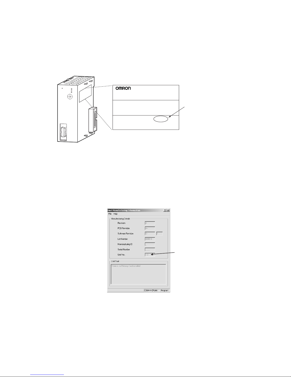
Notation of Unit Versions
on Products
The unit version is given to the right of the lot number on the nameplate of the
products for which unit versions are being managed, as shown below.
The unit version of Position Control Units starts with unit version 1.0
for the CJ1W-NCF71 and unit version 1.3 for the CS1W-NCF71.
Confirming Unit Versions
with Support Software
CX-Programmer version 4.0 or higher can be used to confirm the unit version
using the Unit Manufacturing Information.
1,2,3... 1. In the IO Table Window, right-click the Position Control Unit and select Unit
Manufacturing information.
2. The following Unit Manufacturing information Dialog Box will be displayed.
Use the following display to confirm the unit version of the Position Control
Unit connected online.
The unit version is displayed as 1.0 in the Unit Version Number field of the
above example.
Using Unit Version Label A unit version label is provided with the Position Control Unit. This label can
be attached to the front of the Position Control Unit to differentiate between
Position Control Units with different unit versions.
CJ1W-NCF71
NC UNIT
Lot No. 040401 0000 Ver.1.0
OMRON Corporation MADE IN JAPAN
Example: CJ1W-NCF71
RU
N
E
R
C
ER
H
E
R
M
M
LK
N
C
F71
U
N
IT
No.
M
LK
0
1
2
3
4
5
6
7
8
9
A
B
C
D
E
F
Unit version
Example for unit version 1.0
Product nameplate
Unit version
Page 17

xviii
Functions Supported According to Position Control Unit Versions
Support Software and Unit Version Support
Function support that depends on the combination of the software version of the CX-Motion-NCF Support Software and the unit version of the Position Control Unit is as shown in the following table.
Note The function to re-establishing connections added in the unit version 2.0 is not
supported by the CX-Motion-NCF. The Position Control Unit communicates
with all of axes registered in a scan list when the CX-Motion-NCF starts communications between a Position Control Unit and a Servo Drive. The connected axis designation will be invalid.
Model CJ1W-NCF71/CS1W-NCF71
Unit Ver. 1.0 Unit Ver. 1.1 Unit Ver. 1.2 Unit Ver. 1.3 Unit Ver. 2.0
Linear interpolation Not supported. Supported. Supported. Supported. Supported.
Setting up an absolute encoder Not supported. Not supported. Supported. Supported. Supported.
Resetting the error counter Not supported. Not supported. Not supported. Supported. Supported.
Establishing connections when there are
unconnected axes or alarms that cannot
be reset
Not supported. Not supported. Not supported. Supported. Supported.
Transferring Servo parameters when
there is an axis error
Not supported. Not supported. Not supported. Supported. Supported.
Locking the Servo when a software limit
has been detected when using a motor
with an absolute encoder
Not supported. Not supported. Not supported. Supported. Supported.
Detecting drive circuit OFF error only
when the Servo is locked
Not supported. Not supported. Not supported. Supported. Supported.
Allocating H512 and latter addresses in
the Holding Area in function blocks.
Not supported. Not supported. Not supported. Supported. Supported.
SMARTSTEP Junior Servo Drives (R7DZN@-ML2)
Not supported. Not supported. Not supported. Not supported. Supported.
Re-establishing connections Not supported. Not supported. Not supported. Not supported. Supported.
Improving the connection limits when
Servo Drive alarms occur (Possible to
establish connection when A.C90
occurs.)
Not supported. Not supported. Not supported. Not supported. Supported.
Origin Search Operation Mode Not supported. Not supported. Not supported. Not supported. Supported.
Preset function for origin searches Not supported. Not supported. Not supported. Not supported. Supported.
Support Software
function
Support
Software
version
Un it Ve r. 1. 0 Un it Ve r. 1. 1 Unit Ve r. 1.2 Uni t Ver. 1.3 U nit Ver. 2 .0
W-series Servo Drives with
MECHATROLINK communications
1.1 or higher Supported. Supported. Supported. Supported. Supported.
Bundling in CX-One 1.2 or higher Supported. Supported. Supported. Supported. Suppor ted.
Setting up an absolute
encoder
1.3 or higher Not supported. Not supported. Supported. Supported. Supported.
Transferring Servo parameters when there is an axis
error
1.3 or higher Not supported. Not supported. Not supported. Supported. Supported.
Origin Search Operation
Mode added in Position
Control Units with unit version 2.0
1.4 or higher Not supported. Not supported. Not supported. Not supported. Supported.
Preset function for origin
searches added in Position Control Units with unit
version 2.0
1.4 or higher Not supported. Not supported. Not supported. Not supported. Supported.
SMARTSTEP Junior with
Built-in MECHATROLINK-II
Communications
1.4 or higher Not supported. Not supported. Not supported. Not supported. Supported.
Page 18

xix
PRECAUTIONS
This section provides general precautions for using the CX-Motion-NCF software package.
The information contained in this section is important for the safe and reliable application of the CX-Motion-NCF.
You must read this section and understand the information contained before attempting to set up or operate the CXMotion-NCF.
1 Intended Audience . . . . . . . . . . . . . . . . . . . . . . . . . . . . . . . . . . . . . . . . . . . . . xx
2 General Precautions . . . . . . . . . . . . . . . . . . . . . . . . . . . . . . . . . . . . . . . . . . . . xx
3 Safety Precautions. . . . . . . . . . . . . . . . . . . . . . . . . . . . . . . . . . . . . . . . . . . . . . xx
4 Operating Environment Precautions . . . . . . . . . . . . . . . . . . . . . . . . . . . . . . . . xxi
5 Application Precautions . . . . . . . . . . . . . . . . . . . . . . . . . . . . . . . . . . . . . . . . . xxi
Page 19

xx
Intended Audience 1
1 Intended Audience
This manual is intended for the following personnel, who must also have
knowledge of electrical systems (an electrical engineer or the equivalent).
• Personnel in charge of installing FA systems.
• Personnel in charge of designing FA systems.
• Personnel in charge of managing FA systems and facilities.
2 General Precautions
The user must operate the product according to the performance specifications described in the operation manuals.
Before using the product under conditions which are not described in the
manual or applying the product to nuclear control systems, railroad systems,
aviation systems, vehicles, combustion systems, medical equipment, amusement machines, safety equipment, and other systems, machines, and equipment that may have a serious influence on lives and property if used
improperly, consult your OMRON representative.
Make sure that the ratings and performance characteristics of the product are
sufficient for the systems, machines, and equipment, and be sure to provide
the systems, machines, and equipment with double safety mechanisms.
This manual provides information for programming and operating the Unit. Be
sure to read this manual before attempting to use the Unit and keep this manual close at hand for reference during operation.
!WARNING It is extremely important that the CX-Motion-NCF and related devices be used
for the specified purpose and under the specified conditions, especially in
applications that can directly or indirectly affect human life. You must consult
with your OMRON representative before applying Position Control Units and
related devices to the above-mentioned applications.
3 Safety Precautions
!WARNING Do not attempt to take any Unit apart while the power is being supplied. Doing
so may result in electric shock.
!WARNING Never touch any of the terminals while power is being supplied. Doing so may
result in serious electric shock.
!Caution Always back up parameters to the flash memory after it has been transferred
to the Position Control Unit. If transferred data is not backed up in flash memory, the previous settings may be used the next time the power is turned ON,
resulting in a malfunction.
!Caution Confirm safety at the destination node before transferring parameters to
another node. Doing either of these without confirming safety may result in
injury.
!Caution Check that the axis number is correct before operating an axis from the CX-
Motion-NCF.
Page 20

xxi
Operating Environment Precautions 4
4 Operating Environment Precautions
!Caution Do not operate the control system in the following locations:
• Locations subject to direct sunlight.
• Locations subject to temperatures or humidity outside the range specified
in the specifications.
• Locations subject to condensation as the result of severe changes in temperature.
• Locations subject to corrosive or flammable gases.
• Locations subject to dust (especially iron dust) or salts.
• Locations subject to exposure to water, oil, or chemicals.
• Locations subject to shock or vibration.
!Caution Take appropriate and sufficient countermeasures when installing systems in
the following locations:
• Locations subject to static electricity or other forms of noise.
• Locations subject to strong electromagnetic fields.
• Locations subject to possible exposure to radioactivity.
• Locations close to power supplies.
5 Application Precautions
Observe the following precautions when using the CX-Motion-NCF.
• Confirm that the correct unit number is specified for the destination node
before transferring parameters to the Position Control Unit.
• Confirm that set parameters operate properly before using them in actual
applications.
• Always turn ON the power to the Unit again or restart the CPU Bus Unit
after transferring the following parameter settings and writing them to
flash memory. Otherwise, the changed parameter settings will not be
enabled.
• Common parameters
•Axis parameters
• Do not turn OFF the power to the Unit while writing to flash memory.
Doing so may result in damage to the flash memory.
• Confirm that no adverse effect will occur in the system before attempting
any of the following. Not doing so may result in an unexpected operation.
• Changing the operating mode of the PLC (including changing the Startup Mode).
• Force-setting/force-resetting any bit in memory.
• Changing the present value of any word or any set value in memory.
• Do not turn OFF the power to the personal computer while installing or
uninstalling the CX-Motion-NCF. Doing so may result in corrupted data in
the personal computer.
Page 21

xxii
Application Precautions 5
Page 22

1
SECTION 1
CX-Motion-NCF Overview
This section provides an overview of the CX-Motion-NCF, and describes the functions and system configuration required
to operate the CX-Motion-NCF.
1-1 What is CX-Motion-NCF? . . . . . . . . . . . . . . . . . . . . . . . . . . . . . . . . . . . . . . . 2
1-2 System Configuration . . . . . . . . . . . . . . . . . . . . . . . . . . . . . . . . . . . . . . . . . . . 4
1-3 Function List . . . . . . . . . . . . . . . . . . . . . . . . . . . . . . . . . . . . . . . . . . . . . . . . . . 4
1-4 Operation Procedure . . . . . . . . . . . . . . . . . . . . . . . . . . . . . . . . . . . . . . . . . . . . 6
Page 23
2
What is CX-Motion-NCF? Section 1-1
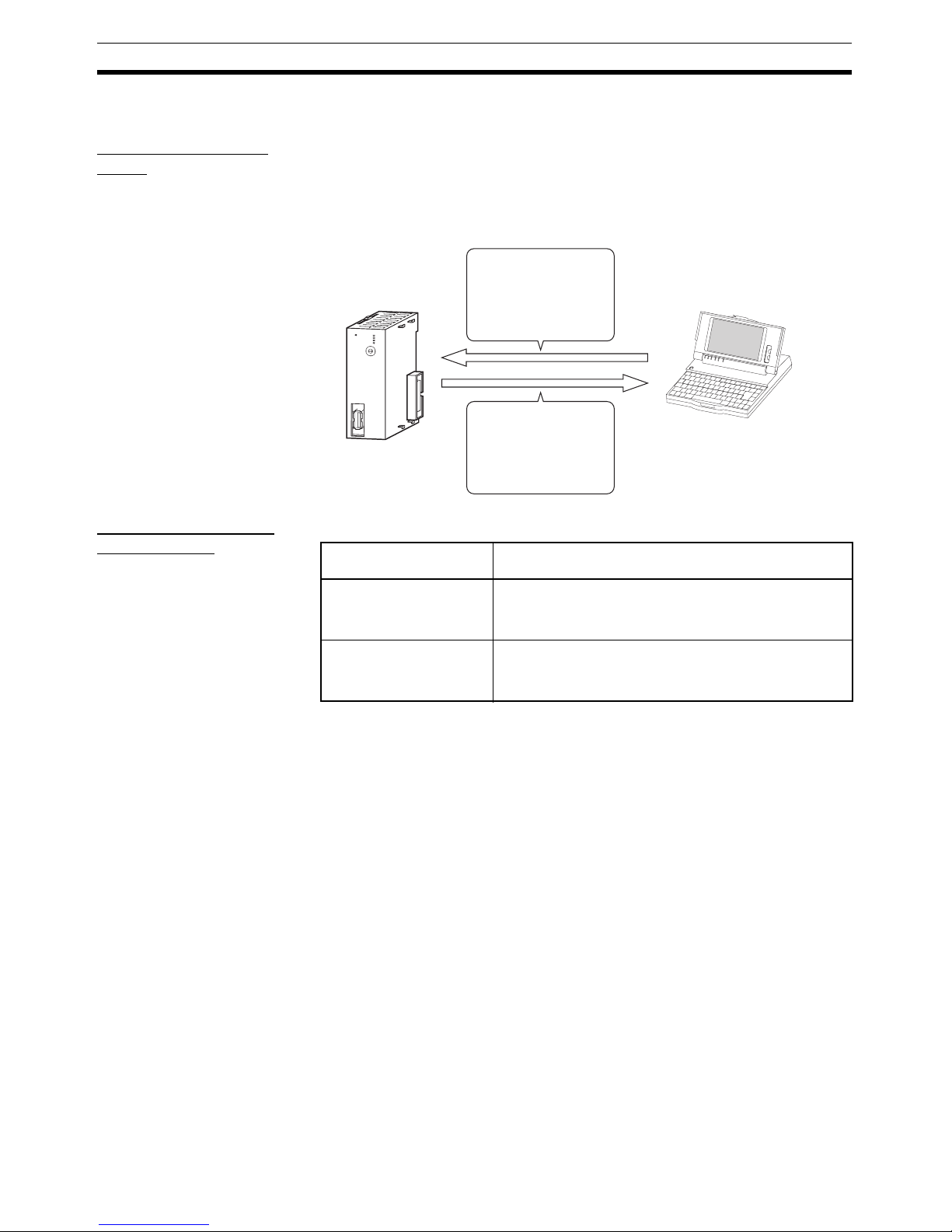
1-1 What is CX-Motion-NCF?
What is CX-MotionNCF?
The CX-Motion-NCF is a software package that helps to set, transfer, save,
and print various data used for the CS1W-NC271/471/F71/CJ1W-NC271/471/
F71 Position Control Units (also referred to as NC Units) and to monitor the
operation status of the Position Control Unit.
The CX-Motion-NCF runs on Windows 2000, XP or Vista.
Applicable Position
Control Units
The CX-Motion-NCF supports the following Position Control Units.
Note Only FQM1 Flexible Motion Controllers with unit version 3.0 or later are sup-
ported.
R
UN
ERC
ER
H
ERM
MLK
NCF71
U
N
IT
No.
M
LK
0
1
2
3
4
5
6
7
8
9
A
B
C
D
E
F
Position Control Unit
Parameters used with
the Position Control Unit
are set and transferred.
The Position Control
Unit's operating status
(e.g., present position,
I/O status, and error
display) is monitored.
Computer with
Windows
operating system
Applicable Position
Control Units
Applicable Controllers
CS1W-NC271
CS1W-NC471
CS1W-NCF71
CS-series PLCs
CJ1W-NC271
CJ1W-NC471
CJ1W-NCF71
CJ-series PLCs, CP-series PLCs, NSJ-series NSJ Controllers, and FQM1 Flexible Motion Controllers (See
note.)
Page 24
3
What is CX-Motion-NCF? Section 1-1
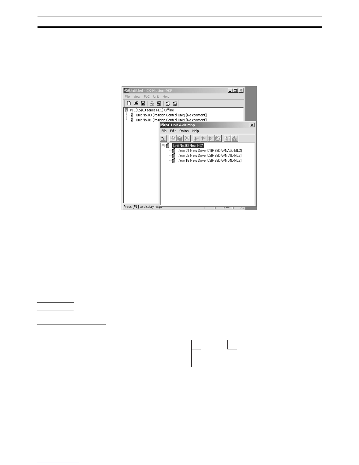
Features
Data Management and
Editing in Project Units
The CX-Motion-NCF manages data for several Position Control Units as one
project. Position Control Units are displayed under a PLC and several Servo
Drives (CS1W-NCF71/CJ1W-NCF71: 16 axes max., CS1W-NC471/CJ1WNC471: 16 axes max., CS1W-NC271/CJ1W-NC271: 16 axes max.) are displayed under a Position Control Unit, both in tree format.
Communications with
Position Control Units via
Networks
The CX-Motion-NCF communicates with Position Control Units using CXServer.
Host Link (SYSMAC WAY) or peripheral bus (Toolbus) can be used to perform
online operations (transferring, comparing, and monitoring parameter data)
with the Position Control Unit on the PLC.
Editing Servo Parameters Parameters of Servo Drives connected to a Position Control Unit can be
edited using the CX-Motion-NCF.
Displaying Error
Information
Information on the error that is currently occurring on a Position Control Unit
or the error log can be displayed.
Applicable
Computers
Refer to the CX-One Ver. 3.0 Setup Manual (Cat. No. W463) for the computer
system requirements for the CX-Motion-NCF.
CX-Motion-NCF Data The CX-Motion-NCF is used to create project files with the configuration
shown below. The file extension for project files is .mnf.
Software Structure The CX-Motion-NCF exchanges data (online communications) with Position
Control Units via CX-Server. In order to execute functions online, CX-Server
must be installed on the same computer that has the CX-Motion-NCF
installed.
NC
NC
NC
NC
PLC
Project File
(
*.mnf)
Unit Parameter
Servo Parameter
Page 25
4
System Configuration Section 1-2
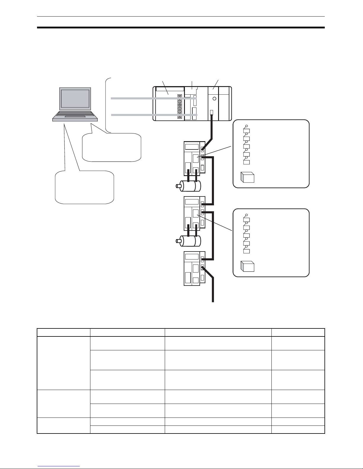
1-2 System Configuration
The system configuration for Position Control Units is shown below.
The example shown here is for the CJ1W-NCF71.
1-3 Function List
Group Function Details Reference
Editing projects Create project Used to create project files (*.mnf) 4-1 Creating a New
Project
Create Position Control Unit Used to add Position Control Unit data to a
project.
4-2 Adding and
Deleting Position
Control Units
Create Servo Drive Used to add Servo Drive data to a project. 4-3 Adding and
Deleting Servo
Drives
Editing data Edit Unit Parameters Used to edit Unit Parameters. 5-1 Editing Unit
Parameters
Edit Servo Parameters Used to edit Servo Parameters. 5-2 Editing Servo
Parameters
Saving and reading
project files
Save project Used to save data as a project file (*.mnf). 6-1 Saving Project
Read project Used to read a project file (*.mnf). 6-2 Reading Project
Toolbus/
Host Link
Power
Supply Unit
CJ-series
CPU Unit
Position Control Unit
(CJ1W-NCF71)
CX-Motion-NCF
Editing/Transferring
parameters
Monitor
File management, etc.
CX-Programmer
Creating/Transferring
ladder program
Monitor
File management, etc.
Servo Drive
Servomotor
Servo Drive
Servo Drive
Servomotor
External input
Forward rotation limit input signal
Reverse rotation limit input signal
Origin input signal
Origin proximity input signal
Interrupt input signal
24-V DC power supply for
interface
:
External input
Forward rotation limit input signal
Reverse rotation limit input signal
Origin input signal
Origin proximity input signal
Interrupt input signal
24-V DC power supply for
interface
MECHATROLINK-II
(16 axes max.)
Page 26

5
Function List Section 1-3
Importing and
exporting data
Import Used to import Unit/Servo Parameters. 6-3 Import
Export Used to export Unit/Servo Parameters. 6-4 Export
Printing Print Used to print the data displayed on the
screen.
6-5 Print
Online Initial setting Used to setup CPU Unit or Position Control
Unit.
7-1 Initial Setting for
Connecting Online
Communications setting Used to make communications settings. 7-2 Setting/Chang-
ing Communications
Specific
Download
Upload
Compare
Used to download, compare, or upload Unit
or Servo Parameters.
7-3 Downloading
Data
7-4 Uploading Data
7-5 Comparing Data
Write to flash memory Used to save the downloaded Unit Parame-
ters.
7-6 Writing to Flash
Memory
Monitor Used to display the Unit's status, axis
present position, axis status, and error information.
8-1 Unit Monitor
8-2 Axis Monitor
Device information Used to read the Position Control Unit
model, Position Control Unit internal software version, and other Unit-related information.
---
Absolute encoder setup Used to set up an absolute encoder. 10-1 Absolute
Encoder Setup
JOG JOG Used to execute JOG operation. 9-1 Test Run
Error Error log Used to display the error log. 11-1 Error Log
Group Function Details Reference
Page 27
6
Operation Procedure Section 1-4
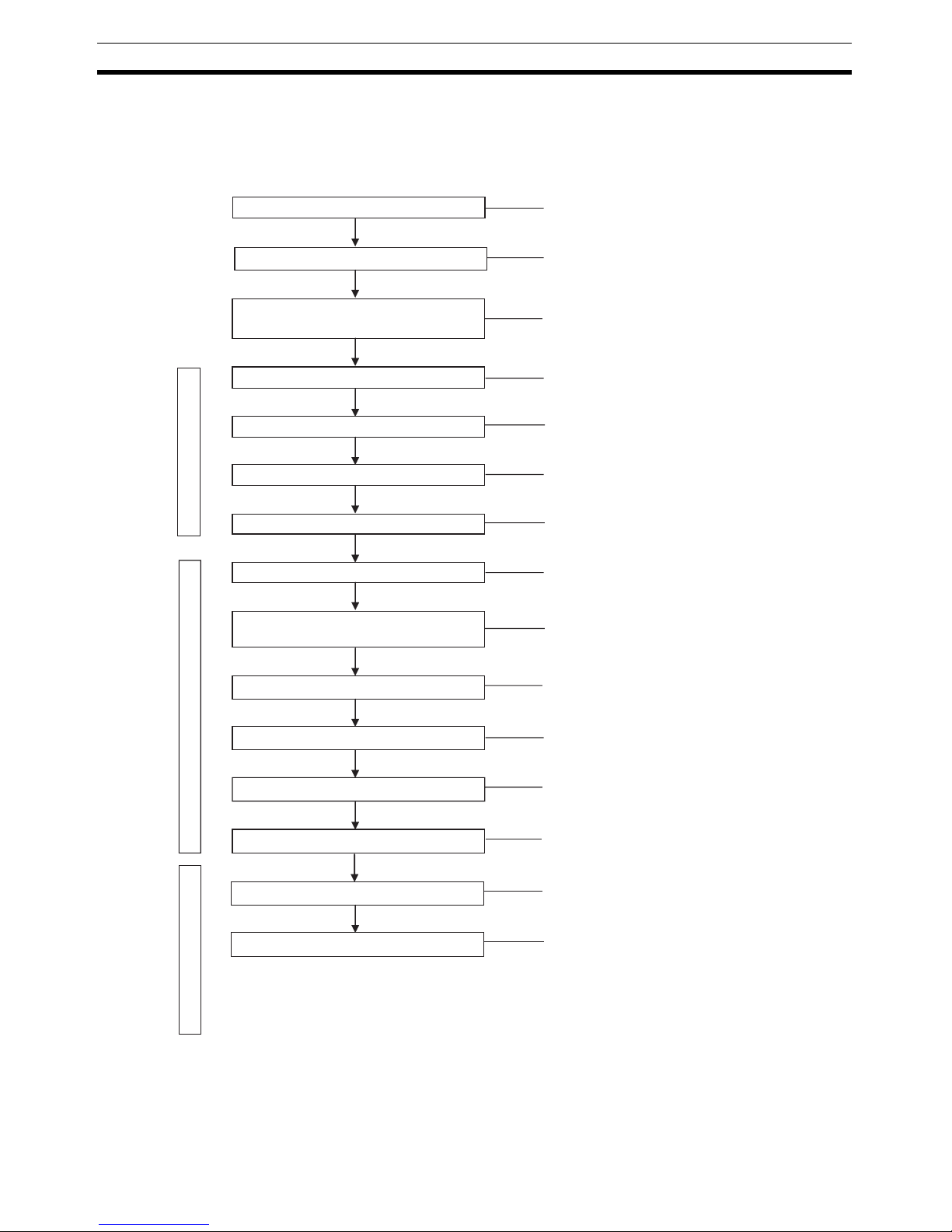
1-4 Operation Procedure
The outline of the procedures required to install the CX-Motion-NCF and CXServer, create various data, transfer it to Position Control Units, and use in
actual operations is shown below.
Installing CX-Server
Installing CX-Motion-NCF
Connecting to Built-in RS-232C port on
CPU Unit
Starting CX-Motion-NCF
Creating a New Project
Adding Position Control Unit to Project
Starting Axis Map Setting Window
CX-Motion-MCF Basic Window
Axis Map Setting Window
CX-Motion-NCF Basic Window
Adding Servo Drive to Position Control Unit
Editing/Transferring Unit
Parameters/Servo Parameters
Writing to Flash Memory
Position Control Unit Positioning Operation
Monitoring
Quitting Axis Map Setting Window
Saving Project
Quitting CX-Motion-NCF
Refer to section 2-1.
Refer to section 2-1.
Refer to section 2-2.
Refer to section 3-2.
Refer to section 4-1.
Refer to section 4-2.
Refer to section 3-2.
Refer to section 4-3.
Refer to sections 5-1, 5-2, 7-3, and 7-4.
Refer to section 7-6.
Refer to the Position Control
Unit's operation manual.
Refer to SECTION 8.
Refer to section 3-2.
Refer to section 6-1.
Refer to section 3-2.
Page 28

7
SECTION 2
Setup
This section provides information on installing the CX-Motion-NCF and CX-Server, and connecting to the PLC.
2-1 Installing and Uninstalling the Software. . . . . . . . . . . . . . . . . . . . . . . . . . . . . 8
2-1-1 Software That Must Be Installed . . . . . . . . . . . . . . . . . . . . . . . . . . . 8
2-2 Connecting to PLC . . . . . . . . . . . . . . . . . . . . . . . . . . . . . . . . . . . . . . . . . . . . . 8
2-2-1 Connecting to CS/CJ-series PLCs . . . . . . . . . . . . . . . . . . . . . . . . . . 8
2-2-2 Connecting to CP-series PLCs . . . . . . . . . . . . . . . . . . . . . . . . . . . . . 10
2-2-3 Connecting to CJ2 PLCs. . . . . . . . . . . . . . . . . . . . . . . . . . . . . . . . . . 11
Page 29
8
Installing and Uninstalling the Software Section 2-1
2-1 Installing and Uninstalling the Software
2-1-1 Software That Must Be Installed
The following software must be installed on the same computer to use the CXMotion-NCF.
1,2,3... 1. CX-Motion-NCF
2. CX-Server (the communications driver)
Installing of CX-MotionNCF
Refer to the CX-One Ver. 3.0 Setup Manual (Cat. No. W463) (supplied with
the CX-One FA Integrated Tool Package) for information on how to install or
uninstall the CX-Motion-NCF from the CX-One FA Integrated Tool Package.
2-2 Connecting to PLC
To transfer the project data that was created using CX-Motion-NCF to the
Position Control Unit. The personal computer and PLC (CPU Unit) must be
physically connected with a cable and also connected online.
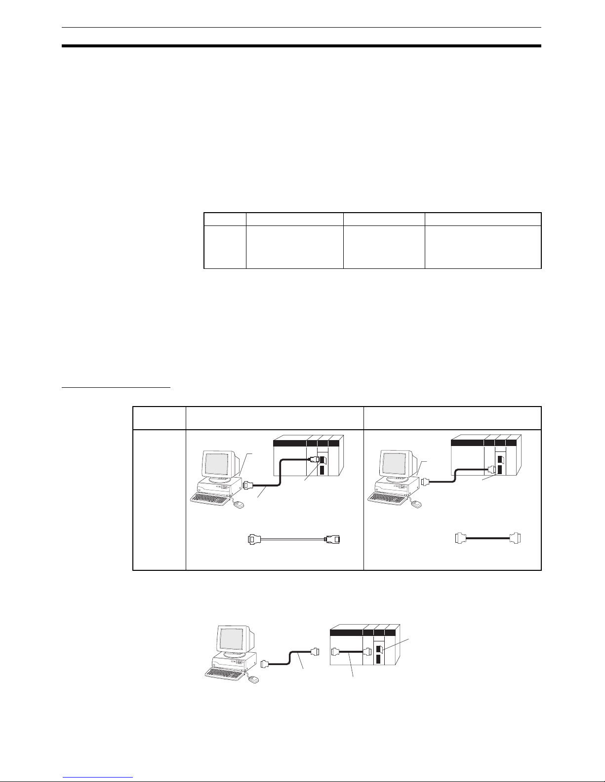
2-2-1 Connecting to CS/CJ-series PLCs
Connection Format Using either the Host Link (SYSMAC WAY) or Toolbus, connect the personal
computer to the peripheral port or RS-232C port on the PLC.
Note The cable model CS1W-CN118 is used as a relay cable to connect the per-
sonal computer to the CPU Unit's peripheral port using the RS-232C cable
(model XW2Z-@@@@-@@) as shown below.
Cat. No. Model Manual name Contents
W463 CXONE-AL@@C-V3/
CXONE-AL@@D-V3
CX-One Ver. 3.0
Setup Manual
An overview of the CX-One
FA Integrated Tool Package
and the CX-One installation
procedure
Personal
computer
Connecting to Peripheral Port Connecting to RS-232C Port
IBM PC/AT
or compatible
N
E
C
P
C
9
8
0
1
B
X
10-pin
CS1W-CN118 (0.1 m) (See note.)
CS1W-CN226 (2.0 m)
CS1W-CN626 (6.0 m)
CS1W-CN118
CS1W-CN226
CS1W-CN626
9-pin
male
9-pin
female
Peripheral port
(10-pin female)
(See note.)
9-pin
female
NE
C
PC
-98
01
B
X
XW2Z-200S-CV / 200S-V (2.0 m)
XW2Z-500S-CV / 500S-V (5.0 m)
XW2Z-200S-CV / -200S-V
XW2Z-500S-CV / -500S-V
9-pin
male
9-pin
female
9-pin
male
9-pin
female
9-pin
male
RS-232C port
(9-pin female)
N
EC
P
C
-9
8
0
1
BX
CS1W-CN118
RS-232C Cable
Peripheral Por
t
Page 30
9
Connecting to PLC Section 2-2
Note Two network types (serial communications mode), SYSMAC WAY and Tool-
bus, are supported when connecting CX-Motion-NCF to the PLC. The characteristics of the network types are as shown below.
Connection Method Use one of the following method to connect the personal computer (CX-
Motion-NCF) and PLC (CPU Unit). It is also possible to connect the personal
computer to the port on the CS/CJ-series Serial Communications Unit. In that
case, the only network type that can be used is Host Link.
Connection Cables
Note When connecting the connectors of the above cables to the PLC's RS-232C
port, discharge any static build-up (e.g., by touching a grounded metal object)
before touching the connectors. Although XW2Z-@@@S-CV Cables use the
anti-static XM2S-0911-E Connector Hood (thus reducing the possibility of
static build-up), be sure to discharge any static as a safety precaution.
Network type Characteristics
Toolbus Faster communications. If possible, use this network type.
• For CS/CJ Series, the baud rate on the peripherals can be
detected automatically, and be connected.
• Only 1 on 1 connection possible.
• For CX-Motion-NCF, it can also be connected to a modem.
SYSMAC WAY
(Host Link)
Used for communications with general host computers.
• Slower than Toolbus.
• Not only 1 on 1 connection, but also 1-many connection possible.
• Connecting to a modem and optical adaptor possible.
Connecting to Peripheral Port Connecting to RS-232C Port
IBM PC/AT or compatible IBM PC/AT or compatible
9-pin connector
9-pin connector
9-pin connector
CS1W-CN118 (0.1 m)
CS1W-CN226 (2.0 m)
CS1W-CN626 (6.0 m)
XW2Z-200S-CV (2.0 m)
XW2Z-500S-CV (5.0 m)
Peripheral port
on CPU Unit
Built-in RS-232C port
on CPU Unit or Serial
Communications Unit
Unit Port on Unit Computer Port on
computer
Network type
(serial commu-
nications
mode)
Model number Length Remarks
CPU Unit Built-in
peripheral
port
IBM PC/AT
compatible
D-Sub, 9pin, male
SYSMAC WAY CS1W-CN226 2 m ---
CS1W-CN626 6 m
Built-in RS232C port
(D-Sub, 9-pin,
female)
IBM PC/AT
compatible
D-Sub, 9pin, male
SYSMAC WAY XW2Z-200S-CV 2 m Uses anti-static
connector
XW2Z-500S-CV 5 m
Serial
Communications
Unit
RS-232C port
(D-Sub, 9-pin,
female)
IBM PC/AT
compatible
D-Sub, 9pin, male
SYSMAC WAY XW2Z-200S-CV 2 m Uses anti-static
connector
XW2Z-500S-CV 5 m
Page 31

10
Connecting to PLC Section 2-2
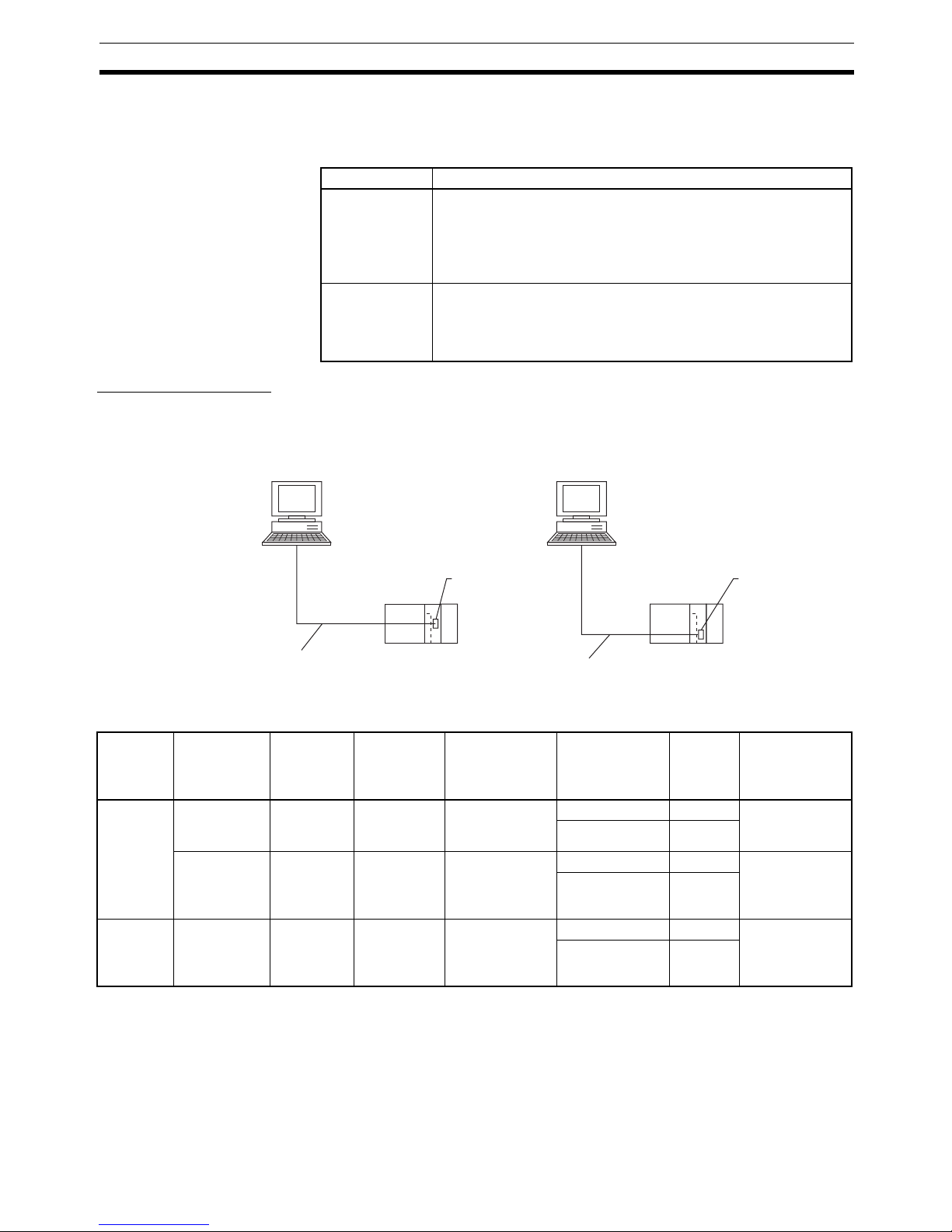
2-2-2 Connecting to CP-series PLCs
Connecting to USB Port on CPU Unit with Commercially Available US Cable
Connecting to RS-232C Port on Serial Communications Board with RS-232C Cable
Unit Port on Unit Computer Port on
computer
Serial communi-
cations mode
(network type)
Model number Length Remarks
CPU Unit USB port
(B connector)
IBM PC/AT
compatible
USB port
(A connector)
USB Commercially available
USB 1.1 or 2.0 cable
5 m
max.
---
IBM PC/AT or
compatible
CP-series CPU Unit
USB port
Commercially
available USB
cable
Peripheral
USB port
Unit Port on
Unit
Computer Port on
computer
Serial communi-
cations mode
(network type)
Model number Length Remarks
CP1W-CIF01
Serial Communications
Board
RS-232C
port, Dsub 9-pin
female
IBM PC/AT
compatible
D-Sub, 9pin, male
Toolbus (Peripheral) or SYSMAC
WAY (Host Link)
XW2Z-200S-CV/500S-CV 2 m/5 m Uses anti-
static connector
SYSMAC WAY
(Host Link)
XW2Z-200S-V/500S-V 2 m/5 m ---
Page 32

11
Connecting to PLC Section 2-2
2-2-3 Connecting to CJ2 PLCs
USB or RS-232C Connection
Note A Host Link (SYSMAC WAY) connection to an RS-232C port on the CPU Unit
or a Serial Communications Unit is not possible for CJ2 PLCs.
Ethernet Connection
Unit Port on Unit Computer Port on
computer
Serial communi-
cations mode
(network type)
Model number Length Remarks
CPU Unit USB port
(B connector)
IBM PC/AT
compatible
USB port
(A connector)
USB Commercially available
USB 1.1 or 2.0 cable
5 m
max.
---
Built-in RS232C port, Dsub 9-pin
female
IBM PC/AT
compatible
D-sub 9-pin,
male
Toolbus (See
note.)
XW2Z-200S-CV/500S-CV2 m/
5 m
Uses
anti-static
connector
USB RS-232C
IBM PC/AT or
compatible
CJ2 CPU Unit
USB
p
ort
Commercially
available USB
cable
USB port
XW2Z-200S-CV/500S-CV
Connecting Cable
Serial port
(RS-232C):
D-sub connector
(9-pin female)
D-sub connector
(9-pin male)
IBM PC/AT or
compatible
CJ2 CPU Unit
Port on Unit Port on computer Serial communi-
cations mode
(network type)
Model number Length Remarks
Built-in EtherNet/
IP port
Ethernet port 100Base-TX/
10Base-T (Recommended:
100Base-TX)
Commercially
available twisted
cable based on
EtherNet/IP standard
100 m (between
hub and node)
---
Commercially
available switching hub
---
Switching
hub
100Base-TX
twisted-pair cable
(straight)
100Base-TX
twisted-pair cable
(straight)
Built-in EtherNet/IP port
IBM PC/AT or
compatible
CJ2 CPU Uni
t
Page 33

12
Connecting to PLC Section 2-2
Page 34

13
SECTION 3
Basic Operation
This section describes each of the screens and basic operations.
3-1 Screen Name . . . . . . . . . . . . . . . . . . . . . . . . . . . . . . . . . . . . . . . . . . . . . . . . . . 14
3-2 Basic Operation. . . . . . . . . . . . . . . . . . . . . . . . . . . . . . . . . . . . . . . . . . . . . . . . 17
3-2-1 CX-Motion-NCF Basic Operation . . . . . . . . . . . . . . . . . . . . . . . . . . 17
3-2-2 Axis Map Setting Window Basic Operation. . . . . . . . . . . . . . . . . . . 21
3-3 Operations Listed by Purpose . . . . . . . . . . . . . . . . . . . . . . . . . . . . . . . . . . . . . 24
Page 35

14
Screen Name Section 3-1
3-1 Screen Name
The window names for the CX-Motion-NCF are shown here.
Basic Window
CX-Motion-NCF Basic Window
Axis Map Setting Window
Page 36

15
Screen Name Section 3-1
Edit Parameter Windows
Page 37

16
Screen Name Section 3-1
Monitor Windows
Axis Monitor Window Unit Monitor Window
Page 38

17
Basic Operation Section 3-2
3-2 Basic Operation
3-2-1 CX-Motion-NCF Basic Operation
The basic operations of the CX-Motion-NCF are explained here.
Starting CX-Motion-NCF
Starting CX-Motion-NCF Using Start Special Application - Start with Settings Inherited from the I/O
Table Window Opened from the CX-Programmer That Was Installed from the CX-One
1,2,3... 1. Right-click a Position Control Unit in the I/O Table Window and select Start
Special Application - Start with Settings Inherited from the pop-up
menu.
2. The CX-Motion-NCF will be started, a new project will be created, and a
Position Control Unit will be added automatically. The Position Control Unit
model will be inherited as shown below
Device type inherited from I/O Tables
Position Control Unit model inherited
from I/O Tables.
▼
▼
Page 39

18
Basic Operation Section 3-2
Starting CX-Motion-NCF Using Start Special Application - Start Only from the I/O Table Window
Opened from the CX-Programmer That Was Installed from the CX-One
Right-click a Position Control Unit in the I/O Table Window and select Start
Special Application - Start Only from the pop-up menu. The following win-
dow will be displayed with a new project.
Starting CX-Motion-NCF
from Windows Start Menu
Select Start - Programs - OMRON - CX-One - CX-Motion-NCF - CXMotion-NCF. The same window as when selecting Start Only will be dis-
played with a new project.
Quitting CX-Motion-NCF
1,2,3... 1. Select File - Exit or click the Close Button at the top right corner of the win-
dow. After editing a project, if the project has not been saved, the following
dialog box will be displayed.
2. Click the Yes Button to save the changes made. Click the No Button if it is
not necessary to save the changes. Click the Cancel Button to return to
the Basic Window without quitting the CX-Motion-NCF.
Page 40

19
Basic Operation Section 3-2
CX-Motion-NCF Basic
Window
The CX-Motion-NCF Basic Window is shown below.
Main Menus
Main Menu Items The names and functions for all of the menus are given in the following table.
When an item is selected, the dialog box for that function is displayed. follow
the instructions in the dialog box.
Main Menu Contents Keyboard
shortcut
File Used to create or save projects. Alt+F
View Used to display or hide Toolbar or Status Bar. Alt+V
PLC Used to connect to PLC. Alt+P
Unit Used to add or delete Position Control Unit, or to open
Axis Map Setting Window.
Alt+U
Help Used to display help and version information. Also used
to register online.
Alt+H
Main menu Item Contents Keyboard
shortcut
File New Creates a new project file. Ctrl+N
Open Opens an existing project file. Ctrl+O
Save Saves the active project (over-
writes the previous data).
Ctrl+S
Save As Saves the active project with a
new name.
---
Exit Quits the CX-Motion-NCF. ---
View Toolbar Displays/hides toolbar. ---
Status Bar Displays/hides status bar. ---
PLC Online Connects to PLC. ---
Communication Settings
Sets communications for online
connection.
---
Page 41

20
Basic Operation Section 3-2
Toolbar Functions can be executed directly by clicking the appropriate icon on the
toolbar. The functions that can be executed from the toolbar are given below.
Status Bar The following information is displayed on the status bar.
View Settings The view settings can be used to display or hide the toolbar or status bar.
View/Hide Settings
1,2,3... 1. Click View.
2. If a check appears next to Toolbar or Status Bar, the corresponding item is
displayed. To hide any of these, select Toolbar or Status Bar to remove
the check.
Unit Edit Parameters Opens Axis Map Setting Window. ---
Change Axis Type Changes the model of the Position
Control Unit (i.e., the axis type that
is connected).
---
Change Unit No. Changes Unit No. of Position Con-
trol Unit.
---
Edit Comment Edits comment. ---
Add Adds Position Control Unit to a
project.
---
Delete Deletes Position Control Unit from
a project.
---
Help Help Index Displays the table of contents for
help.
F1
Online Registration Connects to the OMRON CX-One
Website for online user registration.
---
About CX-Motion
NCF...
Displays the version information
for the CX-Motion-NCF.
---
Main menu Item Contents Keyboard
shortcut
Number Function
(1) Creates a new project.
(2) Opens an existing project.
(3) Saves the active project.
(4) Connects online to PLC.
(5) Displays communications settings window to connect to PLC.
(6) Adds a new Position Control Unit.
(7) Deletes a Position Control Unit.
(1) (2) (3) (4) (5) (6) (7)
Page 42

21
Basic Operation Section 3-2
Help
Displaying the Help Contents
1,2,3... 1. Select Help - Help Index. The table of contents for help will be displayed.
2. Select an item to display information related to that item.
Displaying CX-MotionNCF and CX-Server
Version Information
Select Help - About CX-Motion-NCF. The CX-Motion-NCF and CX-Server
version information will be displayed.
3-2-2 Axis Map Setting Window Basic Operation
The basic operations of the Axis Map Setting Window used to make the Position Control Unit settings are explained here.
Starting the Axis Map
Setting Window
Select a Position Control Unit in the CX-Motion-NCF Basic Window and select
Unit - Edit Parameters, or double-click a Position Control Unit.
Quitting Axis Map
Setting Window
Select File - Exit, or click the Close Button at the right top corner of the Axis
Map Setting Window.
Axis Map Setting
Window
The Axis Map Setting Window is shown below.
Page 43

22
Basic Operation Section 3-2
Main Menus
Main Menu Items The names and functions for all of the menus are given below. When an item
is selected, the dialog box for that function is displayed. Follow the instructions
in the dialog box.
Main menu Contents Keyboard
shortcut
File Used, for example, to import or export. Alt+F
Edit Used, for example, to add Servo Drives or edit parame-
ters.
Alt+E
Online Used, for example, to transfer parameters or monitor
Position Control Units or axes.
Alt+L
Help Used to display help and version information. Alt+H
Main menu Item Contents Keyboard
shortcut
File Import Imports entire Position Control
Unit project files or Servo Parameters. The file is to be in CSV format.
---
Export Exports entire Position Control
Unit project files or Servo Parameters. The file is to be in CSV format
---
Properties When a Servo Drive item has
been selected, displays the
Servo Drive Properties Window.
Invalid when no Servo Drive item
has been selected.
---
Print Prints out Unit Parameters or
Servo Parameters.
Ctrl+P
Close Closes Axis Map Setting Win-
dow.
Closes all the active Edit Parameters and Monitor Windows.
---
Edit New Driver Displays the New Driver Dialog. ---
Edit Parameters
NC Unit Edits Unit Parameters. ---
Axis Edits Servo Parameters. ---
Copy Copies an axis. Ctrl+C
Paste Pastes an axis. Ctrl+V
Delete Deletes the selected Servo
Drive.
DEL
Page 44

23
Basic Operation Section 3-2
Toolbar Functions can be executed directly by clicking the appropriate icon on the
toolbar. The functions that can be executed from the toolbar are given below.
Help
Displaying the Help Contents
1,2,3... 1. Select Help - Help. The table of contents for help will be displayed.
2. Select an item to display information related to that item.
Displaying CX-MotionNCF and Servo Drive
Database Version
Information
Select Help - About. The CX-Motion-NCF and Servo Drive database version
information will be displayed.
Online Download to NC Unit Executes batch download. Dis-
plays the Batch Download Dialog.
---
Upload from NC Unit Executes batch upload. Dis-
plays the Batch Upload Dialog.
---
Compare Executes batch compare. Dis-
plays the Batch Compare Dialog.
---
Write Flash Memory Writes data to flash memory. ---
Unit Monitor Starts Unit Monitor. ---
Axis Monitor Starts Axis Monitor. ---
Test Run Displays the Test Run Window.
Connection status, Servo Lock/
Unlock, JOG, etc. can be controlled.
---
Error Log Displays error log. ---
Device Information Displays device information. ---
Absolute Encoder
Setup
Used to set up an absolute
encoder.
---
Help Help Displays help. F1
About Displays the version information
for the CX-Motion-NCF and
Servo Drive database.
---
Main menu Item Contents Keyboard
shortcut
Number Function
(1) Adds a new Servo Drive.
(2) Copy
(3) Paste
(4) Remove
(5) Download to Position Control Unit
(6) Upload from Position Control Unit
(7) Compare
(8) Writes data to flash memory.
(9) Unit Monitor
(10) Axis Monitor
(1) (2) (3) (4) (5) (6) (7)
(8) (9) (10)
Page 45

24
Operations Listed by Purpose Section 3-3
3-3 Operations Listed by Purpose
Operations Listed by Purpose
Function (Purpose) Operation Keyboard
shortcut
Toolbar
icon
Page
Project
Starting CX-Motion-NCF Select Start - Programs - OMRON - CX-One -
CX-Motion-NCF and select CX-Motion-NCF.
--- --- 17
Creating a new project Select File - New in the CX-Motion-NCF Basic
Window.
Ctrl+N 28
Opening a project Select File - Open in the CX-Motion-NCF Basic
Window.
Ctrl+O 44
Saving (overwriting) Select File - Save in the CX-Motion-NCF Basic
Window.
Ctrl+S 44
Saving with a different
name
Select File - Save As in the CX-Motion-NCF Basic
Window.
--- --- 44
Quitting CX-Motion-NCF Select File - Exit in the CX-Motion-NCF Basic Win-
dow.
--- --- 18
Adding a Position Control Unit
Select Unit - Add in the CX-Motion-NCF Basic
Window.
--- 29
Importing Parameters Select a Position Control Unit in the Axis Map Set-
ting Window and then select File - Import, or right-
click the Position Control Unit and select Import
from the pop-up menu.
--- --- 45
Exporting All the Parameters
Select a Position Control Unit in the Axis Map Setting Window, and then select File - Export, or rightclick the Position Control Unit and select Export
from the pop-up menu.
--- --- 45
Exporting Servo Parameters
Select a Servo Drive in the Axis Map Setting Window, and then select File - Export, or right-click the
Servo Drive and select Export from the pop-up
menu.
--- --- 46
Displaying Servo Drive
Properties
Select a Servo Drive in the Axis Map Setting Window and then select File - Properties, or right-click
the Servo Drive and select Properties from the
pop-up menu.
--- --- ---
Opening Axis Map Setting Window
Select a Position Control Unit in the CX-MotionNCF Basic Window. Select Unit - Edit Parame-
ters, or double-click the Position Control Unit.
--- --- 21
Closing Axis Map Setting
Window
Select File - Close in the Axis Map Setting Window.
--- --- 21
Adding a Servo Drive In the Axis Map Setting Window, select Edit - New
Driver, or right-click a Position Control Unit and
select New Driver from the pop-up menu.
--- 30
Deleting a Servo Drive Select a Servo Drive in the Axis Map Setting Win-
dow and then select Edit - Delete, or right-click the
Servo Drive and select Delete from the pop-up
menu.
DEL 31
Printing Select File - Print in the Axis Map Setting Window. Ctrl+P --- 46
Page 46

25
Operations Listed by Purpose Section 3-3
Editing data
Editing Unit Parameters Select Edit - Edit Parameters - NC Unit, or right-
click a Position Control Unit and select Edit Unit
Parameters from the pop-up menu in the Axis Map
Setting Window.
--- --- 34
Editing Servo Parameters Select Edit - Edit Parameters - Axis**, or right-
click a Servo Drive and select Edit Servo Parame-
ters from the pop-up menu in the Axis Map Setting
Window.
--- --- 37
Jumping between windows
Jumps around over Axis Map Setting Window, Edit
Parameter Window, and Monitor Window by clicking the mouse.
Ctrl+Tab or
Ctrl+Shift+Tab
--- ---
Online operations
Starting communications
with PLC
Select PLC - Online in the CX-Motion-NCF Basic
Window.
--- 51
Communications setting Select PLC - Communication Settings in the CX-
Motion-NCF Basic Window.
--- 50
Batch download In the Axis Map Setting Window, select Online -
Download to NC Unit, or right-click a Position
Control Unit and select Download to NC Unit from
the pop-up menu.
--- 52
Batch upload In the Axis Map Setting Window, select Online -
Upload from NC Unit, or right-click a Position
Control Unit and select Upload from NC Unit from
the pop-up menu
--- 57
Batch compare In the Axis Map Setting Window, select Online -
Compare, or right-click a Position Control Unit and
select Compare from the pop-up menu.
--- 61
Writing to flash memory Select Online - Write Flash Memory in the Axis
Map Setting Window.
--- 66
Monitoring Position Control Unit
In the Axis Map Setting Window, select Online -
Unit Monitor, or right-click a Position Control Unit
and select Unit Monitor from the pop-up menu.
--- 70
Monitoring axis In the Axis Map Setting Window, select Online -
Axis Monitor, or right-click a Position Control Unit
or Servo Drive and select Axis Monitor from the
pop-up menu.
--- 73
Error log In the Axis Map Setting Window, select Online -
Error Log, or right-click a Position Control Unit and
select Error Log from the pop-up menu.
--- --- 92
JOG Select Online - Test Run in the Axis Map Setting
Window.
--- --- 84
Displaying device information (Position Control
Unit model and version)
In the Axis Map Setting Window, select Online -
Device Information, or right-click a Position Control Unit and select Device Information from the
pop-up menu.
--- --- ---
Setting up an absolute
encoder
In the Axis Map Setting Window, select Online -
Absolute Encoder Setup - Axis**, or right-click a
Servo Drive and select Absolute Encoder Setup.
--- --- 90
Display settings
Displaying or hiding Toolbar
Select View - Toolbar in the CX-Motion-NCF Basic
Window.
--- --- 19
Displaying or hiding Status Bar
Select View - Status Bar in the CX-Motion-NCF
Basic Window.
--- --- 19
Function (Purpose) Operation Keyboard
shortcut
Toolbar
icon
Page
Page 47

26
Operations Listed by Purpose Section 3-3
Displaying help
Displaying help Select Help - Help Index in the CX-Motion-NCF
Basic Window.
F1 --- 21
Select Help - Help In the Axis Map Setting Window.
F1 --- 23
Online registration Select Help - Online Registration in the CX-
Motion-NCF Basic Window.
--- --- ---
Displaying version information
Select Help - About CX-Motion-NCF. --- --- 21
Function (Purpose) Operation Keyboard
shortcut
Toolbar
icon
Page
Page 48

27
SECTION 4
Creating Projects
This section provides information on creating projects and adding/deleting Position Control Units and Servo Drives.
4-1 Creating a New Project . . . . . . . . . . . . . . . . . . . . . . . . . . . . . . . . . . . . . . . . . . 28
4-2 Adding and Deleting Position Control Units . . . . . . . . . . . . . . . . . . . . . . . . . 29
4-3 Adding and Deleting Servo Drives . . . . . . . . . . . . . . . . . . . . . . . . . . . . . . . . . 30
Page 49

28
Creating a New Project Section 4-1
4-1 Creating a New Project
Creating a New
Project
Use the following procedure to create a new project in the CX-Motion-NCF
Basic Window.
1,2,3... 1. In the CX-Motion-NCF Basic Window, select File - New, press the Ctrl+N
Keys, or click in the toolbar.
2. The PLC Device Type Window will be displayed. Select the PLC Series to
use and click the OK Button.
Note To connect the Position Control Unit to a network, select the PLC Series con-
nected to the personal computer directly. If the PLC with the Position Control
Unit is selected, the communications settings with the PLC and personal computer may not be set correctly.
3. The PLC will be registered in the project.
When the CX-Motion-NCF is started, a CJ2 CPU Unit will be registered in
the project. If the personal computer is connected to a PLC with a CJ2
CPU Unit, use the project that is already being displayed.
Page 50

29
Adding and Deleting Position Control Units Section 4-2
4-2 Adding and Deleting Position Control Units
Adding Position
Control Units to
Projects
A Position Control Unit can be added to the project.
1,2,3... 1. In the CX-Motion-NCF Basic Window, select Unit - Add, click in the
toolbar, or right-click and select Add NC from the pop-up menu.
2. Set the axis type.
Select the axis type of the Position Control Unit.
3. Set the unit number.
Select a unit number for the Position Control Unit as a CPU Bus Unit.
4. Enter a comment. The comment may be omitted.
5. Click the OK Button.
A Position Control Unit will be added to the project.
Page 51

30
Adding and Deleting Servo Drives Section 4-3
Deleting Position Control Units
1,2,3... 1. Selecting the Position Control Unit to be deleted in the CX-Motion-NCF Ba-
sic Window, and then select Unit - Delete, click , or right-click and select Delete from the pop-up menu.
2. A dialog box saying “Delete the selected Unit. Proceed?” will be displayed.
Click the OK Button.
4-3 Adding and Deleting Servo Drives
Adding Servo Drives
to Position Control
Units
Select a Position Control Unit in the CX-Motion-NCF Basic Window, and then
select Unit - Edit Parameters or double-click a Position Control Unit to display the Axis Map Setting Window. In the Axis Map Setting Window, add a
new Servo Drive.
1,2,3... 1. Select Edit - New Driver, click in the toolbar, or right-click the Position
Control Unit and select New Driver from the pop-up menu.
2. Enter the Servo Drive name.
Up to 32 one-byte characters can be entered.
Page 52

31
Adding and Deleting Servo Drives Section 4-3
3. Select the Series.
Click the drop-down list and select an appropriate series.
Note Select OMRON W Series when using an OMRON R88D-WT@ W-
series Servo Drive with a Yaskawa JUSP-NS115 MECHATROLINK-II Application Module. Select OMRON W Series (Built-in
Communications) when using an OMRON R88D-WN@-ML2 W-se-
ries Servo Drive with Built-in MECHATROLINK-II Communications.
Select OMRON SMARTSTEP Junior with Built-in Communications
when using an OMRON SMARTSTEP Junior Servo Drive with
Built-in MECHATROLINK-II Communications (R7D-ZN@-ML2).
Select OMRON G Series (Built-in Communications) when using an
OMRON G-series Servo Drive with Built-in MECHATROLINK-II
Communications (R88D-GN@-ML2).
4. Select the Servo Drive Model.
Click the drop-down list and select an appropriate Servo Drive model. The
Servo Drive models in the list depends on the selected Series.
5. Select the Version.
Click the drop-down list and select an appropriate version. The Servo Drive
versions in the list depends on the selected Servo Drive model.
6. Set the Axis No.
Click the drop-down list and select an axis number. The axis numbers that
are already in use will not be displayed.
7. Enter the Comment.
Up to 256 one-byte characters can be entered. The comment may be omitted.
8. Click the OK Button.
A new Servo Drive will be added to the Position Control Unit.
Copying Servo Drives
to Position Control
Units
If a Servo Drive that has been registered under a Position Control Unit in the
Axis Map Setting Window is copied and pasted on the same Position Control
Unit, a new Servo Drive will be added with the lowest axis number that is not
in use. If a Servo Drive that has been registered under a Position Control Unit
is copied and pasted on another Servo Drive (which must be registered in
advance), the parameters of the copied Servo Drive will overwrite the other
Servo Drive.
Deleting Servo Drives
from Position Control
Units
A Servo Drive that has been registered under a Position Control Unit can be
deleted.
Page 53

32
Adding and Deleting Servo Drives Section 4-3
1,2,3... 1. Select the Servo Drive to be deleted in the Axis Map Setting Window, and
then select Edit - Delete, click in the toolbar, press the Delete Key, or
right-click the Servo Drive and select Delete from the pop-up menu.
2. Click the OK Button.
The Servo Drive will be deleted from the Position Control Unit.
Page 54

33
SECTION 5
Editing Data
This section describes the operations used to edit data.
5-1 Editing Unit Parameters . . . . . . . . . . . . . . . . . . . . . . . . . . . . . . . . . . . . . . . . . 34
5-1-1 Editing Memory Area Parameters . . . . . . . . . . . . . . . . . . . . . . . . . . 35
5-1-2 Editing Communications Parameters . . . . . . . . . . . . . . . . . . . . . . . . 36
5-1-3 Editing Axis Parameters . . . . . . . . . . . . . . . . . . . . . . . . . . . . . . . . . . 37
5-2 Editing Servo Parameters . . . . . . . . . . . . . . . . . . . . . . . . . . . . . . . . . . . . . . . . 39
Page 55

34
Editing Unit Parameters Section 5-1
5-1 Editing Unit Parameters
The methods used to edit data are described in this section. For details on the
setting contents, Unit parameters, and Servo Parameters, refer to the CS1W-
NC/271/471/F71/CJ1W-NC271/471/F71 Position Control Units Operation
Manual (Cat. No. W426).
1,2,3... 1. Select Edit - Edit Parameters - NC Unit in the Axis Map Setting Window,
double-click a Position Control Unit, or right-click and select Edit Unit Pa-
rameters from the pop-up menu. The Edit Unit Parameter Window will be
displayed.
Note (1) It can be executed only when the connection to the PLC has been estab-
lished in the CX-Motion-NCF Basic Window.
(2) “All the parameters that are set in the Edit Unit Parameter Window” indi-
cates the parameters that are set in Memory Area Setting, Communications Setting, and Axis Setting.
Item Explanation
Download Downloads all the parameters that are set in the Edit Unit Parame-
ter Window to a Position Control Unit. (See notes 1 and 2.)
Upload Uploads all the parameters that are set in the Edit Unit Parameter
Window from a Position Control Unit. (See notes 1 and 2.)
Compare Compares all the parameters that are set in the Edit Unit Parame-
ter Window with the parameters saved in a Position Control Unit.
(See notes 1 and 2.)
Initialize Initializes all the parameters (see note 2) that are set in the Edit
Unit Parameter Window to their default settings.
OK Saves the parameters that are set in the Edit Unit Parameter Win-
dow.
Cancel Cancels the parameters that are set in the Edit Unit Parameter
Window.
Page 56

35
Editing Unit Parameters Section 5-1
5-1-1 Editing Memory Area Parameters
Edit Memory Area
Parameter Window
Select Memory Area Setting from the tree.
Editing Memory Area Parameters
1,2,3... 1. Set the Output Memory Area (PLC to Position Control Unit).
Click the drop-down list of the Output Memory Area (PLC to Position Control Unit) and select an appropriate area type from the list.
In the right box, set the beginning address of the specified area type. The
setting range varies depending on the selected area type and the largest
axis No. of the registered axes. When a value out of the range is entered,
the value will be displayed in red. Enter a value within the range.
2. Set the Input Memory Area (Position Control Unit to PLC)
Click the drop-down list of the Input Memory Area (Position Control Unit to
PLC) and select an appropriate area type from the list.
In the right box, set the beginning address of the specified area type. The
setting range varies depending on the selected area type and the largest
axis No. of the registered axes. When a value out of the range is entered,
the value will be displayed in red. Enter a value within the range.
Note When selecting the same area type for the Output and Input Memory Areas,
make sure to set the appropriate beginning addresses so that the areas do
not overlap. Do not set EM banks that do not exist in the PLC being used as
the areas used for the Output and Input Memory Areas.
Page 57

36
Editing Unit Parameters Section 5-1
5-1-2 Editing Communications Parameters
Edit Communications
Parameters Window
Select Communications Setting from the tree.
Editing
Communications
Parameters
For details of the communications settings, refer to SECTION 6 MECHATROLINK in the CS1W-NCF71/CJ1W-NCF71 Position Control Units Opera-
tion Manual (Cat. No. W426).
1,2,3... 1. Set Transfer Cycle.
Click the drop-down list of the Transfer Cycle and select an appropriate
Transfer Cycle.
2. Set Communications Cycle.
The setting range is between 1 and 32. The set value is used as the multiplier with which the Transfer Cycle is multiplied. When a value out of the
setting range is entered, the value will be displayed in red. Enter a value
within the range.
3. Set No. of Communications Retries.
The setting range is between 0 to 7. When a value out of the setting range
is entered, the value will be displayed in red. Enter a value within the range.
4. Set C2 Master Connection.
Click the drop-down list of the C2 Master Connection and select whether
the C2 Master is connected or not.
Note (1) Set the Communications and Transfer Cycles so that the following ex-
pression is satisfied: Transfer Cycle
× Communications Cycle (Multiplier)
≤ 32 ms
(2) When connecting to a combination of a W-series Servo Drive and the
JUSP-NS115, set the communications cycle to an integer multiple of
1.0 ms.
(3) When connecting to a W-series Servo Drive with Built-in Communica-
tions, set the communications cycle to an integer multiple of 0.5 ms.
(4) When connecting to a SMARTSTEP Junior with Built-in Communications,
set the transfer cycle to 1.0 ms or more.
Page 58

37
Editing Unit Parameters Section 5-1
(5) When connecting to a combination of a W-series Servo Drive and the
JUSP-NS115, to a W-series Servo Drive with Built-in Communications, or
to a G-series Servo Drive with Built-in Communications, set the transfer
cycle to 4 ms or less.
Automatic
Communications
Setting
By clicking the Auto Communications Setting Button, the Communications
and Transfer Cycles corresponding to the largest axis No. registered in the
Position Control Unit are set to their minimum values.
For details on the values of the Communications Parameters set in Automatic
Communications Setting, refer to 6-2-3 MECHATROLINK Communications
Settings in the CS1W-NCF71/CJ1W-NCF71 Position Control Units Operation
Manual (Cat. No. W426).
5-1-3 Editing Axis Parameters
Edit Axis Parameter Window
1,2,3... 1. To edit Axis Parameters, click the Plus Icon left of the Axis Setting in the
tree in the Edit Unit Parameter Window at first. The registered axes will be
displayed.
Note When no axes are registered, the Axis Parameters cannot be edited in the
Edit Unit Parameter Window. Register axes in the Axis Map Setting Window
first and edit the Axis Parameters. Once axes are registered in the Axis Map
Setting Window, they will be automatically displayed in the Edit Unit Parameter Window.
Largest axis
No.
Transfer Cycle Communica-
tions Cycle
No. of Communications
Retries
C2 Master
Connection
1 to 4 1.0 ms × 1 (1.0 ms) 1 No C2 Master
5 to 8 1.0 ms × 2 (2.0 ms) 1 No C2 Master
9 to 10 2.0 ms × 1 (2.0 ms) 1 No C2 Master
11 to 16 2.0 ms × 2 (4.0 ms) 1 No C2 Master
Page 59

38
Editing Unit Parameters Section 5-1
2. Select Axis@@, where @@ is the number of the axis to be edited (@@: 01
to 16).
Editing Axis Parameters
1,2,3... 1. Select the Encoder Type.
Select from either Absolute Encoder or Incremental Encoder.
2. Set the Origin Search Operation.
Select one of the following:
Reversal Mode 1, Reversal Mode 2, Single-direction Mode, or Reversal
Mode 3.
3. Set the Origin Detection Method.
Select either With Origin Proximity Reversal, No Origin Proximity Reversal,
or Not Use Origin Proximity.
4. Set the Origin Search Direction.
Select either Forward or Reverse.
5. Set the Preset When Origin Search.
Select either Not Set or Set.
6. Select the Interrupt Input Signal.
Click the drop-down list and select a signal used as the Interrupt Input Signal.
7. Select the Origin Input Signal.
Click the drop-down list and select a signal used as the Origin Input Signal.
Note (1) Make sure that the same direction is set for Origin Search Direction in the
Axis Parameters and Zero Point Return Direction in the Servo Parameters. Setting different directions may result in a malfunction. (The Origin
Search Direction parameters are as follows: W Series (with and without
built-in communications) and SMARTSTEP Junior (with built-in communications): Pn816.0, G Series (with built-in communications): Pn204.)
(2) When using an absolute encoder, make sure that the settings for the En-
coder Type in the Axis Parameters and Operation Switch when Using Absolute Encoder in the Servo Parameters match. If the settings do not
match, ORIGIN SEARCH execution will not be possible, or another mal-
Page 60

39
Editing Servo Parameters Section 5-2
function may occur. (The Using Absolute Encoder parameters are as follows: W Series (with and without built-in communications): Pn002.2, G
Series (with built-in communications): Pn00B.)
(3) When setting Reversal Mode 3 for the Origin Search Operation, Not Use
Origin Proximity cannot be set for the Origin Detection Method.
(4) When using an Absolute Encoder and the Preset When Origin Search
setting, only Reversal Mode 1 can be set for the Origin Search Operation.
Quitting Editing Click the OK Button. Once all the editing is completed, click the OK Button to
finalize the edited data.
To cancel the edited data, click the Cancel Button.
5-2 Editing Servo Parameters
In the Axis Map Setting Window, select Edit - Edit Parameters - Axis@@,
double-click an axis to be edited, or right-click an axis to be edited and select
Edit Servo Parameters from the pop-up menu. (@@: 01 to 16) The Edit
Servo Parameter Window will be displayed.
Editing Servo Parameters
1,2,3... 1. Select a parameter to be edited.
Edit a parameter either by entering a value or by selecting a value from the
drop-down list for each bit of the parameter.
For parameters whose bits are to be set, click the Plus Icon on the left to
display the parameters for each bit.
Item Explanation
Download Downloads Servo Parameters to a Servo Drive
Upload Uploads Servo Parameters from a Servo Drive.
Compare Compares the Servo Parameters on the computer with the ones in
the Servo Drive.
Initialize Initializes the Servo Parameters to their default settings.
OK Saves the parameters that are set in the Edit Servo Parameter
Window.
Cancel Cancels the parameters that are set in the Edit Servo Parameter
Window.
Page 61

40
Editing Servo Parameters Section 5-2
Entering Value Directly for Parameter
Move to the Setting Value Column of the parameter to be edited using the
mouse or cursor keys.
Selecting Value from Drop-down List for Each Bit of Parameter
Move to the Setting Value Column of the parameter to be edited using the
mouse or cursor keys.
2. Set a Value.
Set a value either by entering a value directly or by selecting a value from
the drop-down list.
Page 62

41
Editing Servo Parameters Section 5-2
Entering Value Directly for Parameter
Either enter a value after double-clicking the Setting Value Column or enter
a value directly. After entering a value, press the Enter Key to save the setting. Once the setting value is changed, the check box of the parameter will
show a check.
Selecting Value from Drop-down List for Each Bit of Parameter
Select a value from the drop-down list. Once the setting value is changed,
the check box of the parameter and each bit will show a check.
Initializing Servo
Parameters
Click the Initialize Button. A confirmation dialog box will be displayed.
Click the OK Button. All the parameters will be set back to their default settings. Once initialization is completed, checks in the check box will be cleared.
Quitting Editing Click the OK Button. Once all the editing is completed, click the OK Button to
save the edited data.
To cancel the edited data, click the Cancel Button.
Page 63

42
Editing Servo Parameters Section 5-2
Page 64

43
SECTION 6
Saving and Reading Projects
This section describes the operations used to save and read newly created projects.
6-1 Saving Project . . . . . . . . . . . . . . . . . . . . . . . . . . . . . . . . . . . . . . . . . . . . . . . . . 44
6-2 Reading Project. . . . . . . . . . . . . . . . . . . . . . . . . . . . . . . . . . . . . . . . . . . . . . . . 44
6-3 Import . . . . . . . . . . . . . . . . . . . . . . . . . . . . . . . . . . . . . . . . . . . . . . . . . . . . . . . 45
6-4 Export . . . . . . . . . . . . . . . . . . . . . . . . . . . . . . . . . . . . . . . . . . . . . . . . . . . . . . . 45
6-5 Print. . . . . . . . . . . . . . . . . . . . . . . . . . . . . . . . . . . . . . . . . . . . . . . . . . . . . . . . . 46
Page 65

44
Saving Project Section 6-1
6-1 Saving Project
Saving Project To save a project, select File - Save or File - Save As in the CX-Motion-NCF
Basic Window.
When editing a project that was saved before and saving it again with the
same name, select File - Save. The project will be overwritten. When saving a
new project or saving a project with a different name, select File - Save As.
Saving Project with Name
1,2,3... 1. Select File - Save As. The following window will be displayed.
2. Enter or select the folder to be saved in, the file name, and the file type (use
the default file type: *.mnf), and then click the Save Button.
6-2 Reading Project
Reading Project To read a project that has already been saved, select File - Open in the CX-
Motion-NCF Basic Window.
1,2,3... 1. Select File - Open in the CX-Motion-NCF Basic Window.
2. From the Look in drop-down list, select the drive and folder to which the file
was saved.
3. Enter the project name, or select one from the file list. Set the File of type:
field to *.mnf.
4. Click the Open Button.
Page 66

45
Import Section 6-3
6-3 Import
Importing File Files saved in CSV format can be imported as project data.
If a CSV file contains Unit and Servo Parameters, the axis map in the
imported file will be adopted.
If a CSV file contains Servo Parameters only, a new Servo Drive will be added
to the axis map. In this case, the lowest axis No. not in use will be allocated to
the Servo Drive automatically.
In the Axis Map Setting Window, select File - Import, or right-click a Position
Control Unit and select Import from the pop-up menu.
6-4 Export
Exporting All Data Unit Parameters and registered Servo Parameters can be saved in CSV for-
mat.
Select a Position Control Unit in the Axis Map Setting Window, and then select
File - Export, or right-click the Position Control Unit and select Export from
the pop-up menu.
Note Files exported from CX-Motion-NCF version 1.4 or higher cannot be imported
to CX-Motion-NCF version 1.3 or lower. Set the Save as type Box to Unit
Parameter file in Ver1.3 or lower to export a file that can be imported to CXMotion-NCF version 1.3 or lower. Unit Parameter file in Ver1.3 or lower can be
set only when the Unit is the CS1W-NCF71/CJ1W-NCF71 (the axis type is
16).
Page 67

46
Print Section 6-5
Exporting Servo
Parameters Alone
Selected Servo Parameters can be saved in CSV format.
Select a Servo Drive in the Axis Map Setting Window, and then select File -
Export, or right-click the Servo Drive and select Export from the pop-up
menu.
6-5 Print
Printing Procedure
1,2,3... 1. In the Axis Map Setting Window, select File - Print. The following window
will be displayed.
2. Select parameters to be printed out and click the OK Button.
3. The Print Dialog Box will be displayed. Select a printer, specify the number
of copies, and make appropriate page setup. Then click the OK Button.
Note Parameters that are being edited will not be reflected in printing. To reflect the
parameters in printing, close the Edit Parameter Window and then select File
- Print.
Page 68

47
Print Section 6-5
Print Samples An example of printed Unit Parameters is shown below.
Page 69

48
Print Section 6-5
An example of printed Servo Parameters is shown below. The setting value
0000H is expressed in hexadecimal. Other values are expressed in decimal.
Page 70

49
SECTION 7
Transferring and Comparing Data
This section describes the operations used to transfer or compare data between the personal computer and Position Control
Unit/Servo Drive, and to write data transferred to the Position Control Unit to the Position Control Unit's flash memory.
Note Make sure that the personal computer is connected to the PLC via a connecting cable and that online
communications are enabled before transferring or comparing data, or writing data to flash memory.
7-1 Initial Setting for Connecting Online . . . . . . . . . . . . . . . . . . . . . . . . . . . . . . . 50
7-2 Setting/Changing Communications Specific . . . . . . . . . . . . . . . . . . . . . . . . . 50
7-3 Downloading Data . . . . . . . . . . . . . . . . . . . . . . . . . . . . . . . . . . . . . . . . . . . . . 52
7-3-1 Batch Downloading . . . . . . . . . . . . . . . . . . . . . . . . . . . . . . . . . . . . . 52
7-3-2 Downloading Unit Parameters . . . . . . . . . . . . . . . . . . . . . . . . . . . . . 54
7-3-3 Downloading Servo Parameters . . . . . . . . . . . . . . . . . . . . . . . . . . . . 56
7-4 Uploading Data . . . . . . . . . . . . . . . . . . . . . . . . . . . . . . . . . . . . . . . . . . . . . . . . 57
7-4-1 Batch Uploading. . . . . . . . . . . . . . . . . . . . . . . . . . . . . . . . . . . . . . . . 57
7-4-2 Uploading Unit Parameters. . . . . . . . . . . . . . . . . . . . . . . . . . . . . . . . 59
7-4-3 Uploading Servo Parameters . . . . . . . . . . . . . . . . . . . . . . . . . . . . . . 60
7-5 Comparing Data . . . . . . . . . . . . . . . . . . . . . . . . . . . . . . . . . . . . . . . . . . . . . . . 61
7-5-1 Batch Comparing . . . . . . . . . . . . . . . . . . . . . . . . . . . . . . . . . . . . . . . 61
7-5-2 Comparing Unit Parameters . . . . . . . . . . . . . . . . . . . . . . . . . . . . . . . 63
7-5-3 Comparing Servo Parameters . . . . . . . . . . . . . . . . . . . . . . . . . . . . . . 64
7-6 Writing to Flash Memory . . . . . . . . . . . . . . . . . . . . . . . . . . . . . . . . . . . . . . . . 66
Page 71

50
Initial Setting for Connecting Online Section 7-1
7-1 Initial Setting for Connecting Online
Initial Settings for CPU Unit and Position Control Unit
1,2,3... 1. Set the unit number for the Position Control Unit (using the rotary switch on
the front panel)
2. Set the DIP switch on the CPU Unit or the Controller Section of the NSJ
Controller.
a. For Communications via Toolbus:
• When using the peripheral port, set SW4 to OFF, or set SW4 to ON
and make appropriate setting of PLC Setup (set the PLC Setup Address 160 on the Programming Console to 0400 Hex).
• When using the RS-232C port, set SW5 to ON, or set SW5 to OFF and
make appropriate setting of PLC Setup (set the PLC Setup Address
160 on the Programming Console to 0400 Hex).
b. For Communications via SYSMAC WAY (Host Link):
• When using the peripheral port, set SW4 to ON, or set SW4 to OFF
and make appropriate setting of PLC Setup. (Set the PLC Setup Address 144 on the Programming Console to its default, 0000 Hex. If the
default setting has not been changed, leave the setting as it is.)
• When using the RS-232C port, set SW5 to OFF, or set SW5 to ON and
make appropriate setting of PLC Setup. (Set the PLC Setup Address
160 on the Programming Console to its default, 0000 Hex. If the default
setting has not been changed, leave the setting as it is.)
3. Create the I/O tables (using the CX-Programmer or a Programming Console).
7-2 Setting/Changing Communications Specific
Communications Setting
1,2,3... 1. In the CX-Motion-NCF Basic Window, select PLC - Communications Set-
ting, click in the toolbar, or right-click and select Communications
Setting from the pop-up menu. The following dialog box will be displayed.
2. Select the Network Type.
Click the drop-down list of the Network Type and select an appropriate network type.
3. Select the Baud Rate.
Click the drop-down list of the Baud Rate and select an appropriate baud
rate.
4. Detailed Settings
For more detailed settings, click the Settings Button.
Page 72

51
Setting/Changing Communications Specific Section 7-2
Setting the Network Tab Page
Setting the Driver Tab Page
Click the OK Button.
Ends the detailed settings and returns to the Communications Setting Window.
5. Click the OK Button.
Ends the communications setting.
Connecting to PLC In the CX-Motion-NCF Basic Window, select PLC - Online, click in the
toolbar, or right-click the PLC and select Online from the pop-up menu.
Page 73

52
Downloading Data Section 7-3
7-3 Downloading Data
The object of downloading varies depending on the operation method.
Batch Downloading Downloads Unit Parameters and Servo Parameters of all the Servo Drives
registered in the Axis Map Setting Window.
Downloading Unit
Parameters
Downloads Unit Parameters.
Downloading Servo
Parameters
Downloads Servo Parameters.
Note Before starting MECHATROLINK communications, make sure that the PLC is
in the PROGRAM Mode. Otherwise, the axis may start moving suddenly due
to the ladder execution.
Before disconnecting MECHATROLINK communications, make sure that the
axis is not operating. Disconnecting MECHATROLINK communications will
put the operating axis in the Servo Free state.
Before restarting the Position Control Unit, make sure that the axis is not operating. Restarting the Position Control Unit will put the operating axis in the
Servo Free state.
7-3-1 Batch Downloading
1,2,3... 1. In the Axis Map Setting Window, select Online - Download to NC Unit,
click in the toolbar, or right-click a Position Control Unit and select
Download to NC Unit from the pop-up menu.
2. Click the OK Button.
Cancels all the parameters being edited and closes the Edit Windows.
Page 74

53
Downloading Data Section 7-3
3. Click the OK Button to start downloading Unit Parameters to the Position
Control Unit. Clicking the Cancel Button during the download will cancel
downloading, however, the parameters that were downloaded before the
cancellation will already be downloaded to the Position Control unit.
4. If the communications between the Position Control Unit and Servo Drive
are established after the download is completed, the following dialog box
will be displayed to confirm whether to release the connection.
5. Click the OK Button to release the connection. The following dialog box will
be displayed to confirm whether to restart the Position Control Unit.
6. Clicking the OK Button will restart the Position Control Unit to enable the
registered scan list. After being restarted, Servo Parameters will be transferred to the Servo Drive.
Note Servo Parameters of the axis registered in the Axis Map Setting
Window as Unknown Model will not be transferred.
Page 75

54
Downloading Data Section 7-3
7. Click the OK Button.
If the Servo Drive models do not match at this point, the following confirmation message will be displayed.
8. Click the OK Button to establish the connection and transfer Servo Parameters to the Servo Drive.
Clicking the Cancel Button will cancel transferring, however, the parameters that were transferred before the cancellation will already be transferred to the Servo Drive.
9. When the Download to NC Unit Dialog Box is closed, the download will be
completed.
Note When the MECHATROLINK communications cannot be started, only Unit
Parameters will be downloaded.
7-3-2 Downloading Unit Parameters
1,2,3... 1. Click the Download Button in the Edit Unit Parameter Window. The follow-
ing dialog box will be displayed.
To write Unit Parameters to the flash memory after downloading, select the
checkbox for writing to flash memory.
!Caution After downloading Unit Parameters to the Position Control Unit, always
backup the parameters in the flash memory. Otherwise, the parameter settings before the download will be enabled when the power is turned ON next
time (i.e. the downloaded parameters will be lost and not be reflected), which
may cause the machines to operate in an unexpected way.
Page 76

55
Downloading Data Section 7-3
2. Click the OK Button.
If the communications between the Position Control Unit and Servo Drive
are established at this point, the following dialog box will be displayed to
confirm whether to release the connection or not.
3. Click the OK Button to release the connection and start downloading Unit
Parameters to the Position Control Unit.
Clicking the Cancel Button will cancel downloading, however, the parameters that were downloaded before the cancellation should be downloaded
to the Position Control Unit.
4. If the checkbox for writing to flash memory was selected a few steps before, the following dialog box will be displayed to confirm that the Position
Control Unit will be restarted to enable the registered axis map after completion of the download.
5. Click the OK Button to restart the Position Control Unit.
6. If the connection was released in step 2, the connection status can be restored (established in this case) here. To establish the connection, click the
OK Button. Otherwise, click the Cancel Button.
7. When the Download to NC Unit Dialog Box is closed, the download will be
completed.
Page 77

56
Downloading Data Section 7-3
7-3-3 Downloading Servo Parameters
1,2,3... 1. Click the Download Button in the Edit Servo Parameter Window.
The checkbox of Selected Parameters will be displayed. To download only
the selected parameters, select the checkbox. If the checkbox is not selected here, all the Servo Parameters will be downloaded.
2. Click the OK Button.
If the communications between the Position Control Unit and Servo Drive
are not established at this point, the following dialog box will be displayed
to confirm whether to establish the connection or not.
3. Click the OK Button to establish the connection and start downloading Servo Parameters to the Servo Drive.
4. If the Servo Drive models do not match at this point, the following confirmation message will be displayed. To continue downloading, click the OK
Button.
5. Clicking the Cancel Button will cancel downloading, however, the parameters that were downloaded before the cancellation should be downloaded
to the Servo Drive.
Page 78

57
Uploading Data Section 7-4
6. If the connection was established at Step 2, the connection status can be
restored (released in this case) here. To release the connection, click the
OK Button. Otherwise, click the Cancel Button.
7. When the Download to NC Unit Dialog Box is closed, the download will be
completed.
Note When the MECHATROLINK communications cannot be started, Servo
Parameters cannot be downloaded. Start the MECHATROLINK communications first and download Servo Parameters.
7-4 Uploading Data
The object of uploading varies depending on the operation method.
Batch Uploading Uploads Unit Parameters and Servo Parameters of all the Servo Drives regis-
tered in the scan list in the Position Control Unit.
Uploading Unit
Parameters
Uploads Unit Parameters.
Uploading Servo
Parameters
Uploads Servo Parameters.
Note Before starting MECHATROLINK communications, make sure that the PLC is
in the PROGRAM Mode. Otherwise, the axis may start moving suddenly due
to the ladder execution.
Before disconnecting MECHATROLINK communications, make sure that the
axis is not operating. Disconnecting MECHATROLINK communications will
put the operating axis in the Servo Free state.
7-4-1 Batch Uploading
1,2,3... 1. In the Axis Map Setting Window, select Online - Upload from NC Unit,
click in the toolbar, or right-click the Position Control Unit and select
Upload from NC Unit from the pop-up menu. The following dialog box will
be displayed.
Page 79

58
Uploading Data Section 7-4
2. Click the OK Button.
Cancels all the parameters being edited and close the Edit Windows.
3. Click the OK Button. Uploading Unit Parameters from the Position Control
Unit will start. Clicking the Cancel Button will cancel the upload.
4. If the connection between the Position Control Unit and Servo Drive is not
established at this point, the following dialog box will be displayed.
5. Click the OK Button to establish the connection and start uploading Servo
Parameters from the Servo Drive.
Clicking the Cancel Button during uploading will cancel the upload.
Page 80

59
Uploading Data Section 7-4
If the connection cannot be established at this point, the following dialog
box will be displayed. Click the OK Button and the axes registered in the
Position Control Unit will be displayed as Unknown Model.
6. If the connection was established at Step 4, the connection status can be
restored (released in this case) here. To release the connection, click the
OK Button. To leave the connection established, click the Cancel Button.
7. When the Upload from NC Unit Dialog Box is closed, the upload will be
completed.
Note Batch uploading will overwrite the parameters on the computer, which means
that the parameters being edited will also be erased.
When the MECHATROLINK communications cannot be started, only Unit
Parameters can be uploaded.
7-4-2 Uploading Unit Parameters
1,2,3... 1. Click the Upload Button in the Edit Unit Parameter Window.
2. Clicking the OK Button will start uploading Unit Parameters from the Position Control Unit.
Clicking the Cancel Button will cancel uploading.
3. When the Upload from NC Unit Dialog Box is closed, the upload will be
completed.
Page 81

60
Uploading Data Section 7-4
Note When the axis map on the computer is different from the scan list in the Posi-
tion Control Unit, Unit Parameters will not be uploaded. Execute batch upload
instead.
7-4-3 Uploading Servo Parameters
1,2,3... 1. Click the Upload Button in the Edit Servo Parameter Window. The follow-
ing dialog box will be displayed.
2. Click the OK Button.
If the connection between the Position Control Unit and Servo Drive are not
established at this point, the following dialog box will be displayed to confirm whether to establish the connection or not.
3. Click the OK Button to establish communications and start uploading Servo Parameters from the Servo Drive.
4. If the Servo Drive models do not match, the following confirmation message will be displayed. To continue uploading, click the OK Button.
5. Click the Cancel Button to cancel uploading.
6. If the connection was established in step 2, the connection status can be
restored (released in this case) here. To release the connection, click the
OK Button. To leave the connection established, click the Cancel Button.
Page 82

61
Comparing Data Section 7-5
7. When the Upload from NC Unit Dialog Box is closed, the upload will be
completed.
Note When the MECHATROLINK communications cannot be started, Servo
Parameters cannot be uploaded. Start the MECHATROLINK communications
first and upload Servo Parameters.
7-5 Comparing Data
The objects of comparing varies depending on the operation method.
Batch Comparing Compares the data on the CX-Motion-NCF with the Unit Parameters and
Servo Parameters of the Servo Drives registered in the scan list in the Position Control Unit.
Comparing Unit
Parameters
Compares the data on the CX-Motion-NCF with the Unit Parameters in the
Position Control Unit.
Comparing Servo
Parameters
Compares the data on the CX-Motion-NCF with the Servo Parameters in the
Servo Drive.
Note Before starting MECHATROLINK communications, make sure that the PLC is
in the PROGRAM Mode. Otherwise, the axis may start moving suddenly due
to the ladder execution.
Before disconnecting MECHATROLINK communications, make sure that the
axis is not operating. Disconnecting MECHATROLINK communications will
put the operating axis in the Servo Free state.
7-5-1 Batch Comparing
1,2,3... 1. In the Axis Map Setting Window, select Online - Compare, click in
the toolbar, or right-click the Position Control Unit and select Compare
from the pop-up menu. The following dialog box will be displayed.
2. Click the OK Button. All the parameters being edited will be discarded and
the Edit Windows will be closed.
Page 83

62
Comparing Data Section 7-5
3. Click the OK Button. Uploading Unit Parameters from the Position Control
Unit will start. Clicking the Cancel Button will cancel the upload.
4. If the communications between the Position Control Unit and Servo Drive
are not established at this point, the following dialog box will be displayed
to confirm whether to establish the connection or not.
5. Click the OK Button to establish the connection and start uploading Servo
Parameters from the Servo Drive.
Clicking the Cancel Button will cancel the upload.
If the connection cannot be established at this point, the following dialog
box will be displayed. Click the OK Button and the axes registered in the
Position Control Unit will be displayed as Unknown Model in the Axis Map
Setting Window.
Page 84

63
Comparing Data Section 7-5
6. If the connection was established in step 4, the connection status can be
restored (released in this case) here. To release the connection, click the
OK Button. To leave the connection established, click the Cancel Button.
7. After completion of uploading Unit and Servo Parameters, they are compared with the parameters on the personal computer. If they match, the following dialog box will be displayed.
If there is any mismatch in the comparison, the following window will be
displayed to show the parameters that did not match.
Note When the MECHATROLINK communications cannot be started, batch com-
paring cannot be executed. Start the MECHATROLINK communications first
and execute batch comparing.
7-5-2 Comparing Unit Parameters
1,2,3... 1. Click the Compare Button in the Edit Unit Parameter Window. The follow-
ing dialog box will be displayed.
Page 85

64
Comparing Data Section 7-5
2. Click the OK Button to start comparing. Uploading Unit Parameters will
start at first.
Clicking the Cancel Button during comparing will cancel comparing.
3. After completion of uploading, the following dialog box will be displayed if
Unit Parameters have no mismatch.
If there is any mismatch in the comparison, the following window will be
displayed to show the parameters that did not match.
7-5-3 Comparing Servo Parameters
1,2,3... 1. Click the Compare Button in the Edit Servo Parameter Window. The fol-
lowing dialog box will be displayed.
Page 86

65
Comparing Data Section 7-5
2. Click the OK Button.
If the communications between the Position Control Unit and Servo Drive
are not established at this point, the following dialog box will be displayed
to confirm whether to establish the connection or not.
3. Click the OK Button to establish the communications and start uploading
Servo Parameters.
4. If the Servo Drive models do not match, the following confirmation message will be displayed. To continue uploading, click the OK Button.
5. Clicking the Cancel Button during comparing will cancel comparing.
6. If the connection was established in step 2, the connection status can be
restored (released in this case) here. To release the connection, click the
OK Button. To leave the connection established, click the Cancel Button.
7. After completion of comparing, the following dialog box will be displayed if
Servo Parameters have no mismatch.
Page 87

66
Writing to Flash Memory Section 7-6
If there is any mismatch in the comparison, the following window will be
displayed to show the parameters that did not match.
Note When the MECHATROLINK communications cannot be started, Servo
Parameters cannot be compared. Start the communications first and compare
Servo Parameters.
7-6 Writing to Flash Memory
Unit Parameters downloaded to the Position Control Unit will be lost when the
power is turned OFF. Therefore, they have to be written to the flash memory to
keep them after powering OFF.
If Unit Parameters were not written to the flash memory during downloading
process, make sure to write them to the flash memory.
Writing to Flash Memory
!Caution After downloading Unit Parameters to the Position Control Unit, always
backup the parameters in the flash memory. Otherwise, the parameter settings before the download will be enabled when the power is turned ON next
time (i.e. the downloaded parameters will be lost and not be reflected), which
may cause the machines to operate in an unexpected way.
1,2,3... 1. Select Online - Write Flash Memory, or click in the toolbar in the Axis
Map Setting Window. The following dialog box will be displayed.
2. Click the OK Button.
If the communications between the Position Control Unit and Servo Drive
are established at this point, the following dialog box will be displayed to
confirm whether to release the connection or not.
Page 88

67
Writing to Flash Memory Section 7-6
3. Click the OK Button.
The following dialog box will be displayed to confirm whether to restart the
Position Control Unit or not. To enable the Unit Parameters written to the
flash memory, the Position Control Unit must be restarted.
4. If the connection was released in step 2, the connection status can be restored (established in this case) here. To establish the connection, click the
OK Button. To leave the connection released, click the Cancel Button.
5. The writing operation is completed when the Write to flash memory window is no longer displayed.
Note If an error occurs in writing to the flash memory, the Unit Parameters may not
be written to the flash memory successfully. In this case, write the Unit Parameters to the flash memory again after resetting the error.
Page 89

68
Writing to Flash Memory Section 7-6
Page 90

69
SECTION 8
Monitor
The Position Control Unit's communications status, error status, and axis's present position and status are displayed in the
Monitor Windows.
Note Make sure that the computer and PLC are connected with the connection cable and the communica-
tions between them are established before starting monitoring operations.
8-1 Unit Monitor . . . . . . . . . . . . . . . . . . . . . . . . . . . . . . . . . . . . . . . . . . . . . . . . . . 70
8-2 Axis Monitor. . . . . . . . . . . . . . . . . . . . . . . . . . . . . . . . . . . . . . . . . . . . . . . . . . 73
Page 91

70
Unit Monitor Section 8-1
8-1 Unit Monitor
In Unit Monitor, communications status, Position Control Unit errors, and
present position of each axis are monitored.
Starting Unit Monitor (Unit Monitor Common Items, Unit Status Monitor, Present
Position Monitor)
1,2,3... 1. In the Axis Map Setting Window, select Online - Unit Monitor, or click
in the toolbar, or right-click the Position Control Unit and select Unit Mon-
itor from the pop-up menu.
If the connection to the Position Control Unit is not established at this point,
the following dialog box will be displayed.
2. Click the OK Button to establish the connection (i.e., start communications).
3. Click to stop monitoring. Clicking the same button again will restart
monitoring.
Page 92

71
Unit Monitor Section 8-1
4. Click the Present Position Tab to display the Present Position Monitor Tab
Page.
5. Click the Close Button or at the right top corner to end monitoring the
Position Control Unit.
Unit Monitor Common Items
Unit Status Monitor
Name Explanation
Title Bar Shows the status of monitoring and communications between
Position Control Unit and Servo Drive.
• Stop: Monitoring stopped.
• Monitoring (Connection Released): Monitoring in progress,
however, communications between Position Control Unit and
Servo Drive have not been started. Therefore, information
about axes is not displayed.
• Monitoring (Connection Established): Entire information is
displayed.
Monitor Start/Stop
Button
Starts monitoring. If communications between Position Control Unit and Servo Drive have not been
started, the connection will be established first.
Stops monitoring.
Close Button Closes the monitor window.
Item Explanation
Scan list Indicates whether the axes are registered in the
scan list or not.
Comm (Communications) status Indicates whether the communications with the
axis 1 to 16 are established or not.
Axis error Displays the axis where an error or warning has
occurred.
With errors:
With warnings:
Page 93

72
Unit Monitor Section 8-1
1,2,3... 1. When an error occurs in the Position Control Unit, the following window will
be displayed.
2. When an error or warning occurs on an axis, the following window will be
displayed.
Unit common
error
Error reset all Pressing this button will reset all the error occur-
ring in the Position Control Unit and Servo
Drives.
Error code Displays the error code of the error occurring in
the Position Control Unit. When there is no error,
the code “0000” is displayed.
Error name Displays the name of the error occurring in the
Position Control Unit.
Item Explanation
Page 94

73
Axis Monitor Section 8-2
Present Position Monitor
Note When performing Unit Monitor, set the Input Memory Area of the Axis Operat-
ing Memory Area Designation in the Edit Unit Parameter Window and transfer
the setting to the Position Control Unit. If it is not set, the data in the Unit is
monitored directly, which makes the response slower.
8-2 Axis Monitor
In Axis Monitor, present values, status, external I/O, and error information of
axes are monitored.
Starting Axis Monitor (Axis Monitor Common Items, Basic Monitor, Status Monitor,
Present Value Monitor)
1,2,3... 1. In the Axis Map Setting Window, select Online - Axis Monitor, click
in the toolbar, or right-click the Position Control Unit or Servo Drive and select Axis Monitor. If the communications between the Position Control
Unit and Servo Drive have not been established at this point, the following
dialog box will be displayed.
Item Explanation
Command value Displays the command value of each axis.
Feedback value Displays the feedback value of each axis.
Monitor all axes with
command unit
If selected (i.e., checked), all the axes will be monitored using
command unit. Pulse rate and unit are set in Axis Monitor.
Page 95

74
Axis Monitor Section 8-2
2. Click the OK Button to start communications (i.e., establish connection).
Page 96

75
Axis Monitor Section 8-2
3. In the drop-down list of Monitored Axes, the axes registered in the scan list
of the Position Control Unit will be displayed. Select axes to be monitored.
Page 97

76
Axis Monitor Section 8-2
4. Click the Basic Monitor Tab to display present values and errors.
5. Click the Status Tab to display all the status information.
Page 98

77
Axis Monitor Section 8-2
6. Click the Present Value Tab to display various present values.
7. Click to stop monitoring. Clicking the same button again will resume
monitoring.
8. Click the Close Button or at the right top corner of the window to close
the Axis Monitor Window.
Note When performing Unit Monitor, set the Input Memory Area of the Axis Operat-
ing Memory Area Designation in the Edit Unit Parameter Window and transfer
the setting to the Position Control Unit. If it is not set, the data in the Unit is
monitored directly, which makes the response slower.
Page 99

78
Axis Monitor Section 8-2
Axis Monitor Common Items
Selected Axis
Status
Basic Monitor
Name Explanation
Title Bar Shows the status of monitoring and communications between
Position Control Unit and Servo Drive.
• Stop: Monitoring stopped.
• Monitoring (Connection Released): Monitoring in progress,
however, communications between Position Control Unit and
Servo Drive have not been started. Therefore, information
about axes is not displayed.
• Monitoring (Connection Established): Entire information is
displayed.
Monitor Start/Stop
Button
Starts monitoring. If communications between Position Control Unit and Servo Drive have not been
started, the connection will be established first.
Stops monitoring.
Close Button Closes the monitor window.
Name Explanation
Selected Axis Specifies axes to be monitored. The axes registered in the
scan list of the Position Control Unit are displayed in the dropdown list.
Name Explanation
Status Communications Status Status of each signal is displayed.
SERVO ON
NC Unit Positioning Completed
No Origin Flag
Brake Output
Forward Rotation Limit Input
Reverse Rotation Limit Input
Origin Proximity Input
Encoder Phase Z Input
External Latch Signal 1 Input
External Latch Signal 2 Input
External Latch Signal 3 Input
Name Explanation
Present Value Present Value
Display
Present position, speed, etc. are displayed.
Monitor Setup
Button
Press this button to change displayed contents,
unit, and pulse rate.
Unit and pulse rate can be set only for the axes
registered in the Axis Map Setting Window.
Page 100

79
Axis Monitor Section 8-2
1,2,3... 1. Click the Setup Button to display the Monitor Setup Window.
2. Specify the type of monitored present value, unit, and pulse rate.
3. Once setup is completed, click the OK Button to save the settings. To discard the settings, click the Cancel Button.
Error Error Status of errors is displayed.
With errors:
With warnings:
Error code When an error occurs, the error code will be dis-
played. When there is no error, the code “0000”
will be displayed. Click the error code to display
help.
Error Name When an error occurs, the error name will be
displayed. Click the error name to display help.
Name Explanation
Name Explanation
Present Value Upper Box Specify the item to be displayed in the upper
box.
• Command Present Position
• Position Deviation
• Feedback Present Position
• Latch Position
• Target Position
• Feedback Speed
• Command Speed
• Target Speed
• Torque Command
Lower Box Specify the item to be displayed in the lower box.
• Command Present Position
• Feedback Present Position
 Loading...