

Omron SYSMAC CV, SYSMAC CV1000, SYSMAC CV2000, SYSMAC CVM1, CV500-LK201 Operation Manual
...Page 1
Cat. No. W205-E1-04
SYSMAC CV-series
CV500/CV1000/CV2000/CVM1
Programmable Controllers
Page 2
SYSMAC CV-series
CV500/CV1000/CV2000/CVM1
Programmable Controllers
Operation Manual:
Host Link System, CV500-LK201 Host Link Unit
Revised May 2002
Page 3

!
!
!
v
Notice:
OMRON products are manufactured for use according to proper procedures by a qualified operator
and only for the purposes described in this manual.
The following conventions are used to indicate and classify precautions in this manual. Always heed
the information provided with them. Failure to heed precautions can result in injury to people or damage to property.
DANGER Indicates an imminently hazardous situation which, if not avoided, will result in death or
serious injury.
WARNING Indicates a potentially hazardous situation which, if not avoided, could result in death or
serious injury.
Caution Indicates a potentially hazardous situation which, if not avoided, may result in minor or
moderate injury, or property damage.
OMRON Product References
All OMRON products are capitalized in this manual. The word “Unit” is also capitalized when it refers
to an OMRON product, regardless of whether or not it appears in the proper name of the product.
The abbreviation “Ch,” which appears in some displays and on some OMRON products, often means
“word” and is abbreviated “Wd” in documentation in this sense.
The abbreviation “PC” means Programmable Controller and is not used as an abbreviation for anything else.
Visual Aids
The following headings appear in the left column of the manual to help you locate different types of
information.
Note Indicates informa t i o n o f particular interest for efficient and convenient operation
of the product.
1, 2, 3... 1. Indicates lists of one sort or another, such as procedures, checklists, etc.
OMRON, 1992
All rights reserved. No part of this publication may be reproduced, stored in a retrieval system, or transmitted, in any
form, or by any means, mechanical, electronic, photocopying, recording, or otherwise, without the prior written permission of OMRON.
No patent liability is assumed with respect to the use of the information contained herein. Moreover, because OMRON is
constantly striving to improve its high-quality products, the information contained in this manual is subject to change
without notice. Every precaution has been taken in the preparation of this manual. Nevertheless, OMRON assumes no
responsibility for errors or omissions. Neither is any liability assumed for damages resulting from the use of the information contained in this publication.
Page 4

TABLE OF CONTENTS
vii
SECTION 1
Introduction 1. . . . . . . . . . . . . . . . . . . . . . . . . . . . . . . . . . . .
1-1 Overview 2. . . . . . . . . . . . . . . . . . . . . . . . . . . . . . . . . . . . . . . . . . . . . . . . . . . . . . . . . . . . . .
1-2 System Configuration 5. . . . . . . . . . . . . . . . . . . . . . . . . . . . . . . . . . . . . . . . . . . . . . . . . . . . .
1-3 Communications Specifications 8. . . . . . . . . . . . . . . . . . . . . . . . . . . . . . . . . . . . . . . . . . . . .
1-4 Gateway Function 9. . . . . . . . . . . . . . . . . . . . . . . . . . . . . . . . . . . . . . . . . . . . . . . . . . . . . . .
SECTION 2
Switch Settings and Communications Parameters 11. . . . .
2-1 CPU Settings and Parameters 12. . . . . . . . . . . . . . . . . . . . . . . . . . . . . . . . . . . . . . . . . . . . . . .
2-2 Host Link Unit Settings and Parameters 13. . . . . . . . . . . . . . . . . . . . . . . . . . . . . . . . . . . . . .
SECTION 3
Installation 25. . . . . . . . . . . . . . . . . . . . . . . . . . . . . . . . . . . . .
3-1 Host Link Unit Dimensions 26. . . . . . . . . . . . . . . . . . . . . . . . . . . . . . . . . . . . . . . . . . . . . . . .
3-2 Mounting the Host Link Unit 27. . . . . . . . . . . . . . . . . . . . . . . . . . . . . . . . . . . . . . . . . . . . . . .
3-3 Connection Cables for the Host Link Unit 27. . . . . . . . . . . . . . . . . . . . . . . . . . . . . . . . . . . .
3-4 RS-232C Connections 28. . . . . . . . . . . . . . . . . . . . . . . . . . . . . . . . . . . . . . . . . . . . . . . . . . . .
3-5 RS-422 Connections 31. . . . . . . . . . . . . . . . . . . . . . . . . . . . . . . . . . . . . . . . . . . . . . . . . . . . . .
3-6 1-to-1 Connection Examples 35. . . . . . . . . . . . . . . . . . . . . . . . . . . . . . . . . . . . . . . . . . . . . . .
3-7 Optical Interface Connections 38. . . . . . . . . . . . . . . . . . . . . . . . . . . . . . . . . . . . . . . . . . . . . .
3-8 1-to-N Connection Example 40. . . . . . . . . . . . . . . . . . . . . . . . . . . . . . . . . . . . . . . . . . . . . . .
3-9 Wiring 42. . . . . . . . . . . . . . . . . . . . . . . . . . . . . . . . . . . . . . . . . . . . . . . . . . . . . . . . . . . . . . . . .
SECTION 4
Communications 47. . . . . . . . . . . . . . . . . . . . . . . . . . . . . . . .
4-1 Initial Communications Test 48. . . . . . . . . . . . . . . . . . . . . . . . . . . . . . . . . . . . . . . . . . . . . . .
4-2 Wrap Communications Test 49. . . . . . . . . . . . . . . . . . . . . . . . . . . . . . . . . . . . . . . . . . . . . . . .
4-3 C-mode Commands 52. . . . . . . . . . . . . . . . . . . . . . . . . . . . . . . . . . . . . . . . . . . . . . . . . . . . . .
4-4 Sending Commands to Host Computers 57. . . . . . . . . . . . . . . . . . . . . . . . . . . . . . . . . . . . . .
4-5 Communications Timing 64. . . . . . . . . . . . . . . . . . . . . . . . . . . . . . . . . . . . . . . . . . . . . . . . . .
SECTION 5
C-mode Commands 71. . . . . . . . . . . . . . . . . . . . . . . . . . . . . .
5-1 C-mode Command List 72. . . . . . . . . . . . . . . . . . . . . . . . . . . . . . . . . . . . . . . . . . . . . . . . . . .
5-2 CIO AREA READ 73. . . . . . . . . . . . . . . . . . . . . . . . . . . . . . . . . . . . . . . . . . . . . . . . . . . . . . .
5-3 LINK AREA READ 73. . . . . . . . . . . . . . . . . . . . . . . . . . . . . . . . . . . . . . . . . . . . . . . . . . . . . .
5-4 HOLDING AREA READ 74. . . . . . . . . . . . . . . . . . . . . . . . . . . . . . . . . . . . . . . . . . . . . . . . .
5-5 PV READ 74. . . . . . . . . . . . . . . . . . . . . . . . . . . . . . . . . . . . . . . . . . . . . . . . . . . . . . . . . . . . . .
5-6 TC STATUS READ 75. . . . . . . . . . . . . . . . . . . . . . . . . . . . . . . . . . . . . . . . . . . . . . . . . . . . . .
5-7 DM AREA READ 75. . . . . . . . . . . . . . . . . . . . . . . . . . . . . . . . . . . . . . . . . . . . . . . . . . . . . . .
5-8 AUXILIARY AREA READ 76. . . . . . . . . . . . . . . . . . . . . . . . . . . . . . . . . . . . . . . . . . . . . . .
5-9 DM AREA READ (FIXED) 76. . . . . . . . . . . . . . . . . . . . . . . . . . . . . . . . . . . . . . . . . . . . . . .
5-10 CIO AREA WRITE 77. . . . . . . . . . . . . . . . . . . . . . . . . . . . . . . . . . . . . . . . . . . . . . . . . . . . . .
5-11 LINK AREA WRITE 77. . . . . . . . . . . . . . . . . . . . . . . . . . . . . . . . . . . . . . . . . . . . . . . . . . . . .
5-12 HOLDING AREA WRITE 78. . . . . . . . . . . . . . . . . . . . . . . . . . . . . . . . . . . . . . . . . . . . . . . .
5-13 PV WRITE 78. . . . . . . . . . . . . . . . . . . . . . . . . . . . . . . . . . . . . . . . . . . . . . . . . . . . . . . . . . . . .
5-14 DM AREA WRITE 79. . . . . . . . . . . . . . . . . . . . . . . . . . . . . . . . . . . . . . . . . . . . . . . . . . . . . .
5-15 AUXILIARY AREA WRITE 79. . . . . . . . . . . . . . . . . . . . . . . . . . . . . . . . . . . . . . . . . . . . . .
5-16 SV READ 1 80. . . . . . . . . . . . . . . . . . . . . . . . . . . . . . . . . . . . . . . . . . . . . . . . . . . . . . . . . . . .
5-17 SV READ 2 81. . . . . . . . . . . . . . . . . . . . . . . . . . . . . . . . . . . . . . . . . . . . . . . . . . . . . . . . . . . .
5-18 SV READ 3 83. . . . . . . . . . . . . . . . . . . . . . . . . . . . . . . . . . . . . . . . . . . . . . . . . . . . . . . . . . . .
Page 5

TABLE OF CONTENTS
viii
5-19 SV CHANGE 1 84. . . . . . . . . . . . . . . . . . . . . . . . . . . . . . . . . . . . . . . . . . . . . . . . . . . . . . . . .
5-20 SV CHANGE 2 85. . . . . . . . . . . . . . . . . . . . . . . . . . . . . . . . . . . . . . . . . . . . . . . . . . . . . . . . .
5-21 SV CHANGE 3 87. . . . . . . . . . . . . . . . . . . . . . . . . . . . . . . . . . . . . . . . . . . . . . . . . . . . . . . . .
5-22 STATUS READ 89. . . . . . . . . . . . . . . . . . . . . . . . . . . . . . . . . . . . . . . . . . . . . . . . . . . . . . . . .
5-23 STATUS WRITE 90. . . . . . . . . . . . . . . . . . . . . . . . . . . . . . . . . . . . . . . . . . . . . . . . . . . . . . . .
5-24 ERROR READ 91. . . . . . . . . . . . . . . . . . . . . . . . . . . . . . . . . . . . . . . . . . . . . . . . . . . . . . . . . .
5-25 FORCED SET 92. . . . . . . . . . . . . . . . . . . . . . . . . . . . . . . . . . . . . . . . . . . . . . . . . . . . . . . . . .
5-26 FORCED RESET 92. . . . . . . . . . . . . . . . . . . . . . . . . . . . . . . . . . . . . . . . . . . . . . . . . . . . . . . .
5-27 FORCED SET/RESET CANCEL 93. . . . . . . . . . . . . . . . . . . . . . . . . . . . . . . . . . . . . . . . . . .
5-28 PC MODEL READ 94. . . . . . . . . . . . . . . . . . . . . . . . . . . . . . . . . . . . . . . . . . . . . . . . . . . . . .
5-29 TEST 94. . . . . . . . . . . . . . . . . . . . . . . . . . . . . . . . . . . . . . . . . . . . . . . . . . . . . . . . . . . . . . . . .
5-30 PROGRAM READ 94. . . . . . . . . . . . . . . . . . . . . . . . . . . . . . . . . . . . . . . . . . . . . . . . . . . . . . .
5-31 PROGRAM WRITE 95. . . . . . . . . . . . . . . . . . . . . . . . . . . . . . . . . . . . . . . . . . . . . . . . . . . . . .
5-32 I/O TABLE GENERATE 95. . . . . . . . . . . . . . . . . . . . . . . . . . . . . . . . . . . . . . . . . . . . . . . . . .
5-33 I/O REGISTER 95. . . . . . . . . . . . . . . . . . . . . . . . . . . . . . . . . . . . . . . . . . . . . . . . . . . . . . . . . .
5-34 ABORT 98. . . . . . . . . . . . . . . . . . . . . . . . . . . . . . . . . . . . . . . . . . . . . . . . . . . . . . . . . . . . . . . .
5-35 Response to an Undefined Command 98. . . . . . . . . . . . . . . . . . . . . . . . . . . . . . . . . . . . . . . .
5-36 INITIALIZE 98. . . . . . . . . . . . . . . . . . . . . . . . . . . . . . . . . . . . . . . . . . . . . . . . . . . . . . . . . . . .
SECTION 6
Maintenance and Troubleshooting 99. . . . . . . . . . . . . . . . . .
6-1 Maintenance 100. . . . . . . . . . . . . . . . . . . . . . . . . . . . . . . . . . . . . . . . . . . . . . . . . . . . . . . . . . . .
6-2 Indicators 101. . . . . . . . . . . . . . . . . . . . . . . . . . . . . . . . . . . . . . . . . . . . . . . . . . . . . . . . . . . . . .
6-3 C-mode Response Codes 103. . . . . . . . . . . . . . . . . . . . . . . . . . . . . . . . . . . . . . . . . . . . . . . . . .
6-4 CV-mode Response Codes 104. . . . . . . . . . . . . . . . . . . . . . . . . . . . . . . . . . . . . . . . . . . . . . . . .
Appendices
A Standard Models 109. . . . . . . . . . . . . . . . . . . . . . . . . . . . . . . . . . . . . . . . . . . . . . . . . . . . . . . . . . .
B Specifications 115. . . . . . . . . . . . . . . . . . . . . . . . . . . . . . . . . . . . . . . . . . . . . . . . . . . . . . . . . . . . .
C Host Link Unit Memory Area Allocations 117. . . . . . . . . . . . . . . . . . . . . . . . . . . . . . . . . . . . . . .
D Sample Programs Including Commands for Host Computer 123. . . . . . . . . . . . . . . . . . . . . . . . .
Glossary 127. . . . . . . . . . . . . . . . . . . . . . . . . . . . . . . . . . . . . . .
Index 143. . . . . . . . . . . . . . . . . . . . . . . . . . . . . . . . . . . . . . . . . .
Revision History 147. . . . . . . . . . . . . . . . . . . . . . . . . . . . . . . . .
Page 6
ix
About this Manual:
This manual describes the host interface built into the SYSMAC CV-series Programmable Controllers
(PCs), and CVM1, and the CV500-LK201 Host Link Unit. The host interface provided by the CPU is functionally the same as the interface provided in the CV500-LK201 Host Link Units. This manual is designed
to accommodate users of either interface type and the user should not feel that both types of interfaces are
required to run a fully operational Host Link System. Many of the features and functions are the same for
both the CPU host interface and Host Link Unit. However, features and functions that dif fer between the
two types of interface are described separately in this manual, and the user should refer to the sections
that apply to the interface being used. 1-1 Overview provides a general description of the Host Link System and the differences between the two types of interface.
This manual is designed to be used together with two other CV-series PC operation manuals and an
installation guide. The entire set of CV-series PC manuals is listed below. Only the basic portions of the
catalog numbers are given; be sure you have the most recent version for your area.
Manual Cat. No.
CV-series PC Installation Guide W195
CV-series PC Operation Manual: SFC W194
CV-series PC Operation Manual: Ladder Diagrams W202
CV-series PC Operation Manual:
Host Link System, CV500-LK201
W205
Programming and operating CV-series PCs are performed with the CV Support Software (CVSS), the
SYSMAC Support Software (SSS), and the CV-series Programming Console for which the following manuals are available.
Product Manuals
CVSS The CV Series Getting Started Guidebook (W203) and the CV Support Software
Operation Manuals: Basics (W196), Offline (W201), and Online (W200).
SSS SYSMAC Support Software Operation Manuals: Basics (W247), C-series PC Op-
erations (W248), and CVM1 Operations (W249)
CV-series Programming
Console
CVM1-PRS21-E Programming Console Operation Manual (W222)
Note The CVSS does not support new instructions added for version-2 CVM1 PCs. The SSS does not
support SFC programming (CV500, CV1000, or CV2000).
Please read this manual completely together with the other CV -series PC and CVSS manuals and be sure
you understand the information provide before attempting to install, program, or operate a CV-series PC.
The basic content of each section of this manual is outlined below.
Section 1 provides an overview of the operation, features, and technical specifications of the Host Link
System. It also describes the types of system configuration available for the Host Link System using either
RS-422 or RS-232C connections.
Section 2 provides information on setting the switches that control communications parameters for the
CPU. These switches can be also be set to use the communications parameters specified in the PC Setup
in the CPU. In addition, this section provides information on the Host Link Unit switches setting and CPU
Bus Unit System Setup parameters that control communications.
Section 3 describes how to connect the Host Link Unit, host link interfaces, Link Adapters, and host computer. Refer to Section 1 Introduction for details on the system configuration. Refer to the CV-series PC
Installation Guide for general installation procedures and precautions.
Section 4 describes both the test methods used to check communications and the specifications of the
commands tha t a r e used for communications control and timing. For communications in CV (FINS) mode,
refer to FINS Command Reference Manual.
Section 5 provides details on all C-mode commands. For basic information on C-mode communications,
refer to 4-3 C-mode Commands.
Section 6 provides information on maintenance and troubleshooting for the Host Link System. For the
troubleshooting of the CPU, refer to the CV-series PC Operation Manual: Ladder Diagrams.
Page 7

x
Four Appendices provide information on standard models, specifications, and Host Link Unit memory
allocations. Sample programs which include commands for the host computer are also provided.
WARNING Failure to read and understand the information provided in this manual may result in
personal injury or death, damage to the product, or product failure. Please read each
section in its entirety and be sure you understand the information provided in the section
and related sections before attempting any of the procedures or operations given.
!
Page 8

1
SECTION 1
Introduction
This section provides an overview of the operation, features, and technical specifications of the Host Link System. It also
describes the types of system configuration available for the Host Link System using either RS-422 or RS-232C connections.
1-1 Overview 2. . . . . . . . . . . . . . . . . . . . . . . . . . . . . . . . . . . . . . . . . . . . . . . . . . . . . . . . . . . . . . .
1-1-1 Communications 2. . . . . . . . . . . . . . . . . . . . . . . . . . . . . . . . . . . . . . . . . . . . . . . . . .
1-1-2 Features 2. . . . . . . . . . . . . . . . . . . . . . . . . . . . . . . . . . . . . . . . . . . . . . . . . . . . . . . . .
1-1-3 Differences between Host Interface and Host Link Unit 3. . . . . . . . . . . . . . . . . . . .
1-1-4 Differences between C-series and CVM1/CV-series Host Links 4. . . . . . . . . . . . .
1-1-5 New/Improved Commands for the CPU Host Interface 5. . . . . . . . . . . . . . . . . . . .
1-2 System Configuration 5. . . . . . . . . . . . . . . . . . . . . . . . . . . . . . . . . . . . . . . . . . . . . . . . . . . . . .
1-2-1 RS-232C 5. . . . . . . . . . . . . . . . . . . . . . . . . . . . . . . . . . . . . . . . . . . . . . . . . . . . . . . . .
1-2-2 RS-422 7. . . . . . . . . . . . . . . . . . . . . . . . . . . . . . . . . . . . . . . . . . . . . . . . . . . . . . . . . .
1-3 Communications Specifications 8. . . . . . . . . . . . . . . . . . . . . . . . . . . . . . . . . . . . . . . . . . . . . .
1-4 Gateway Function 9. . . . . . . . . . . . . . . . . . . . . . . . . . . . . . . . . . . . . . . . . . . . . . . . . . . . . . . .
Page 9
!
2
1-1 Overview
1-1-1 Communications
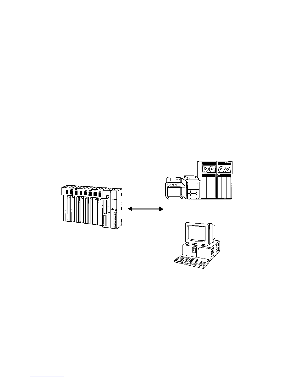
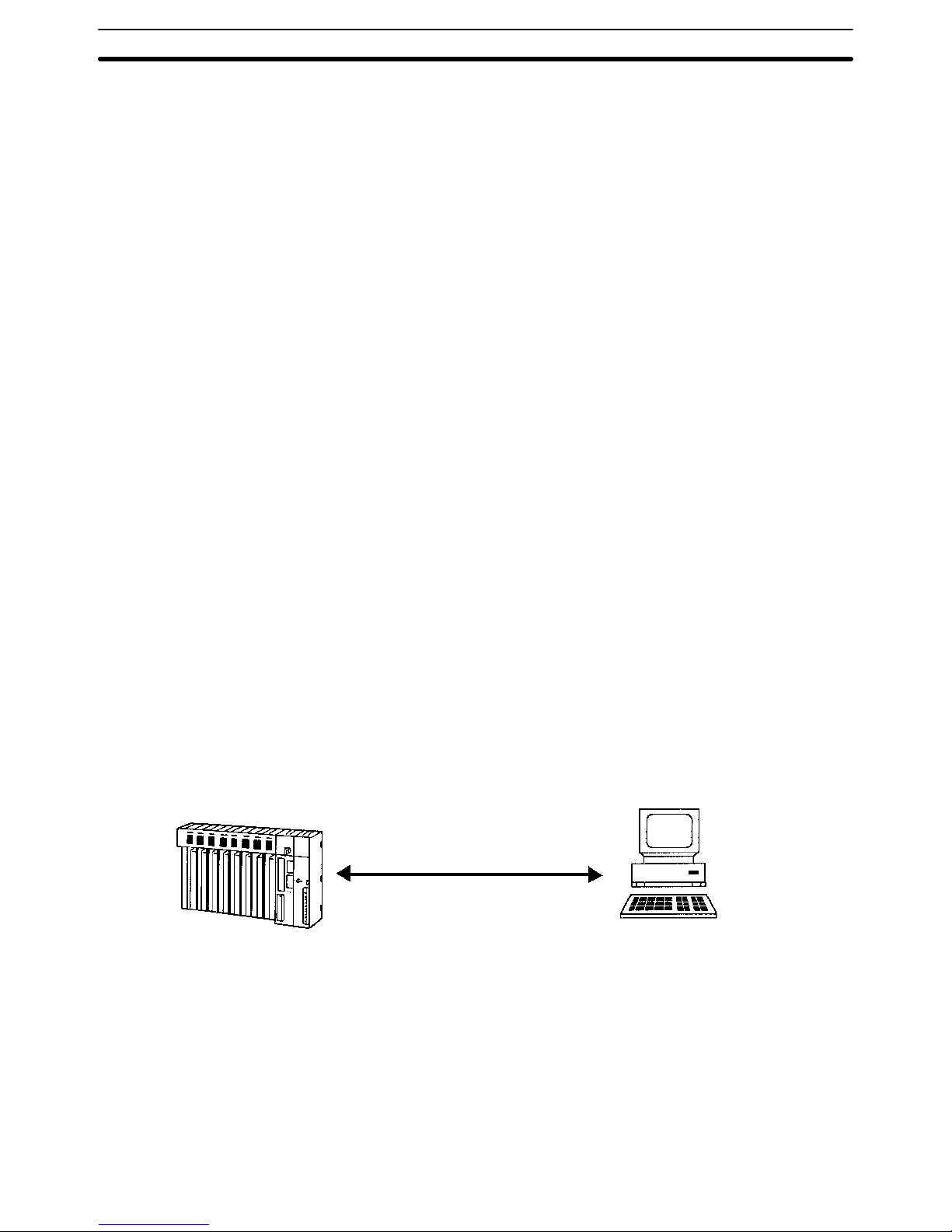
The Host Link System is an optimum and economical communications method
for any size of FA system. The Host Link System can incorporate one or more
host computers interconnected to one or more PCs.
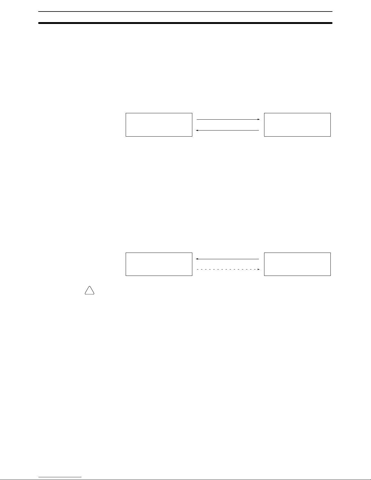
A Host Link System allows a host computer to monitor the operating status and
data areas of the PCs and to control PC operation through transfers of data and
programs.
Host computer
Commands
Responses
CV-series PC
As shown in the figure above, data transfer between the host computer and the
Host Link System is normally initiated when a host computer sends a command
to a PC in the Host Link System. The PC processes each command sent by the
host computer and transmits the results to the host computer.
The user can control the PCs in the Host Link System and monitor operation with
one or more host computers. For example, on a production site, a single host
computer makes it possible to monitor and control the operation of the PCs by
transferring data and programs required for production.
Transmissions from PCs The CV500-LK201 Host Link Unit also allows a CV-series PC to send a com-
mand to a host computer, thus enabling the PC to inform the host computer of
any abnormality arising on the production line that the PC is controlling. The PC
can also communicate with the host computer to check the operating conditions
of the host computer.
Host computer
Commands
Responses
CV-series PC
Caution Transfer only uppercase letters using the host links. Lowercase text cannot be
processed.
1-1-2 Features
CV-series PCs feature a built-in host interface. With this interface, it is possible
to create a Host Link System consisting of CV-series PCs without using any optional Units. When a single interface is not sufficient, however, the
CV500-LK201 Host Link Unit can be mounted to a PC Rack to connect to more
than one host computer . The system created by connecting one or more PCs to
one or more host computers via either the host interface on the CPU or a Host
Link Unit mounted to a PC Rack is called a Host Link System. The main advantages of the Host Link System are described below.
Communications Use either RS-232C or RS-422 communications.
Multiple PCs Connections Up to 32 PCs can be connected to a host computer via RS-422 communications.
Host Monitoring and Control The operating status of the PCs and its memory contents can be monitored and
controlled from the host computer.
New Command System A new command mode called FINS, or CV mode, is provided in addition to the
conventional command mode used by the C-series PCs. Refer to the FINS
Command Reference Manual.
Overview Section 1-1
Page 10

3
Double-check System All communications are subject to a parity check and frame check sequence
(FCS) to help eliminate almost all transmission data errors.
Two Communications Ports The Host Link Unit incorporates two communications ports: a 25-pin RS-232C
port and a 9-pin RS-232C or RS-422 (selectable) port. It is possible to use these
two ports simultaneously , thus allowing the Host Link Unit to connect to two host
computers.
Although the host interface on the CPU allows a host computer to send commands to PCs and the PCs to respond to the commands, the PC cannot send
commands to the host computer. The Host Link Unit, however, makes it possible
for the PCs to send commands to the host computer, thus enabling commands
generated by executing SEND(192), RECV(193), and CMND(194) instructions.
The Host Link Unit also enables any node on the network to send commands to
the host computer, even across multiple network levels.
Note The communications delay varies with the baud rate, the amount of data, and
the PC’s execution method (i.e., synchronous or asynchronous). For example, if
the PC uses synchronous execution, the PC’s cycle time will increase transmission delays. If high-speed processing is required from the host, these factors
must be considered.
1-1-3 Differences between Host Interface and Host Link Unit
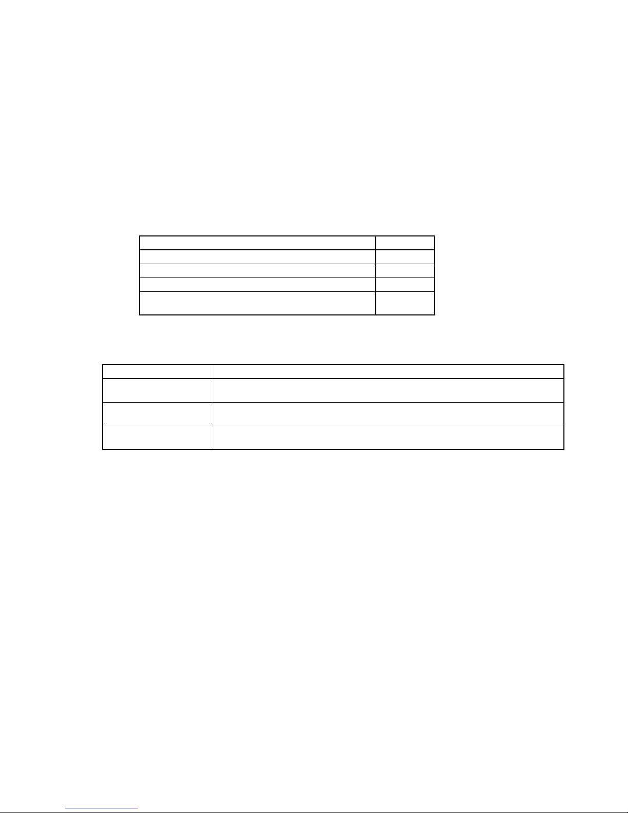
The following table lists the differences between host interface functionality on
the CPU and the functionality of the Host Link Unit.
Feature CPU host interface Host Link Unit
Number of
communications
ports
One: RS-232C/RS-422
(selectable)
Two: RS-232C port and
RS-232C/RS-422 port
(selectable)
Communications
method
Full duplex Half duplex or full duplex
(selectable)
Xon/Xoff control Unavailable Possible using full duplex
communications
CTS signal
control
Unavailable Possible to set the CTS signal
to ON (0 V) continuously.
Unit number Not required Set with the unit number
switch on the front panel.
Node number Set in the PC Setup The node number of port 2 is
set with the node number
switch on the front panel.
The node number of port 1 is
always set to 00.
Optical interface
connection
Power must be supplied from
an AC Adapter.
No AC Adapter is required as
long as port 1 is used because
power is supplied through the
connector.
Wrap
communication
test
Not supported Executed via DIP switch
setting. A connector must be
prepared for a wrap
communication test.
Operating
parameters
Set in the PC Setup. Set in the CPU Bus Unit
System Setup.
Sending
commands to
host computers
Not possible. Possible to send CV-mode
(FINS) commands.
Commands from PC to Host
Computers
Overview Section 1-1
Page 11

4
1-1-4 Differences between C-series and CVM1/CV-series Host Links
This section lists the differences between C-series and CVM1/CV-series Host
Links. Use this information as reference when converting from the C Series to
the CVM1/CV Series.
Frame Size when Dividing Transmissions into Multiple Frames
Item C-series Host Links CVM1/CV-series Host Links
Frame size A total of 29 words of
data is returned in
each frame.
A total of 30 words of data is returned in each
frame.
Applicable
models
C-series Host Link
Units
Built-in RS-232C ports or peripheral ports on
SRM1, CPM1, CPM1A, CQM1, C200HS,
C200HX/HG/HE, and other CPU Units.
CVM1/CV-series built-in Host Links
CV500-LK201 Host Link Unit
Note The user program may need to be altered to enable correct reading of data for
the above difference in frame size. Be sure to check operation and correct the
program as required.
C-mode Commands Not Supported by CVM1/CV-series Host Links
Item C-series Host Links CVM1/CV-series Host Links
Supported
C-mode
commands
All C-mode
commands
The following C-mode commands are
supported only by built-in Host Links for CPU
Unit of version 2 (-V2) or later and cannot be
used on other CVM1/CV-series Host Links.
RL/WR: LINK AREA READ/WRITE
RH:WH: HOLDING AREA READ/WRITE
CR: DM AREA READ/WRITE
R#/R$/R%: SV READ 1/2/3
W#/W$/W%: SV WRITE1/2/3
Note When the model is changed so that the above commands are no longer sup-
ported, change the user program to perform the same operation using other Cmode commands or FINS commands.
Communications Port SignalsDifferent communications signals are used for Host Link communications for the
C Series and CVM1/CV Series depending on the model and the type of port. Differences in the signals are listed below by port.
RS-232C Port
Signals C-series Host Links CVM1/CV-series Host Links
ST1, ST2, RT Used. Not used.
If the SR1, SR2, and RT signals are not used, the same communications cable
can be used even if the model is changed. If the SR1, SR2, and RT signals are
used, synchronized transfer of data will not be possible if the model is changed.
Change the system to sync on the CD (carrier detected) signal. Part of the cable
wiring must also be changed.
RS-422 Port
Signal C-series Host Links CVM1/CV-series Host Links
SG Used by some models:
SG Used
C200H-LK202-V1
3G2A6-LK202-EV1
3G2A5-LK201-EV1
SG Not Used
C500-LK203
Not used.
Overview Section 1-1
Page 12
5
1-1-5 New/Improved Commands for the CPU Host Interface
New C-mode commands have been added for the CPU Host Interface and the
functionality of existing commands has been improved as follows:
New Commands
• RL/WL: Read and write commands for the CIO Area.
• RH/WH: Read and write commands for the CIO Area.
• CR: Read command for the DM Area.
• R#/R$/R%: SV read commands.
• W#/W$/W%: SV change commands.
• *: Initialization command.
Improved Commands
• The Link Area (CIO 1000 to CIO 1063) and Holding Area (CIO 1200 to
CIO 1299) can now be specified for the KS, KR, KC, and QQ commands.
• CVM1-CPU21-EV2 can now be read for the MM command.
The above new and improved commands can also be used with all V1 CPUs
with lot numbers in which the rightmost digit is 5 (jjj5) or higher.
Note The above new and improved commands cannot be used with the
CV500-LK201 Host Link Unit.
1-2 System Configuration
A Host Link System can be connected using RS-232C and/or RS-422 lines.
1-2-1 RS-232C
If a RS-232C line is used to connect a Host Link System, only one PC can be
connected to the host computer.
Transmission Distance The maximum transmission distance varies with the method in which a host
computer and PC are connected. There are three connection methods available: via wire cable, via Optical Fiber Cable and an Optical Interface, and via
optical fiber cable and Link Adapters.
CV-series PC
RS-232C
Host computer (mainframe, personal
computer, or mini-computer)
RS-232C Cable The maximum transmission distance is 15 m if a host computer and PC are con-
nected via RS-232C cable.
Optical Interface The maximum transmission distance is 500 m if a host computer and PC are
connected via two Z3RN-A-5 Optical Interfaces and a Z3F2-4DjM Optical Fi-
ber Cable. The following accessories are necessary. Here, RS-232C cable connects the PC to one Optical Interface and the host computer to the other Optical
Interface, and the Optical Fiber Cable connects the two Optical Fiber Interfaces.
The AC Adapters provide power to the Optical Interfaces.
System Configuration Section 1-2
Page 13
6
Optical Interface The maximum transmission distance is 500 m if a host computer and PC are
connected via two Z3RN-A-5 Optical Interfaces and a Z3F2-4DjM Optical Fi-
ber Cable. The following accessories are necessary. Here, RS-232C cable connects the PC to one Optical Interface and the host computer to the other Optical
Interface, and the Optical Fiber Cable connects the two Optical Fiber Interfaces.
The AC Adapters provide power to the Optical Interfaces. Refer to Appendix B
Specifications for Link Adapters specifications.
Item Model Required
number
Remarks
Optical Interface Z3RN-A-5 2 Converts wire to optical signals.
Optical Fiber Cable
Z3F2-4DjM
1 The box in the model number
indicates one of the following
cable lengths: 1, 5, 10, 20, 30,
50, 100, 200, 400, 500 m.
AC Adapter Z3GP-01 2 5 VAC power supply for Optical
Interfaces
Note The cable connecting the Optical Interface and the connector on the PC (for con-
version between 25 pins and 9 pins) is not available from OMRON.
Link Adapters The host computer and PC can be connected via an optical fiber cable and two
3G2A9-AL004-E (or 3G2A9-AL004-PE) Link Adapters. Here, RS-232C cable
connects the PC to one Link Adapter and the host computer to the other Link
Adapter, and the optical fiber cable connects the two Link Adapters. The maximum transmission distance varies with the kind of optical fiber cable as follows:
Cable 3G2A9-AL004-PE 3G2A9-AL004-E
APF 20 m Connection impossible
PCF 200 m 800 m
APF: all-plastic fiber; PCF: plastic-clad fiber
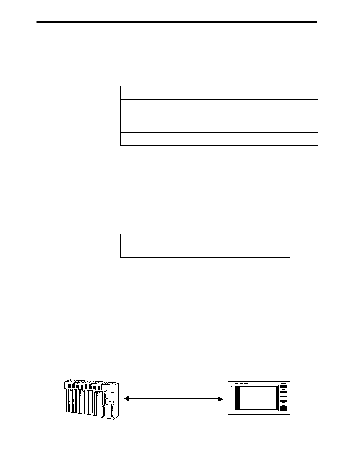
The Host Link System makes it possible for a PC to connect not only to a host
computer but also a Programmable Terminal (PT). The PT connected to the PC
displays information on the system controlled by the PC as well as errors that
may occur in the system.
Note The CPU Unit will change to MONITOR mode if a PT is connected via a Host Link
connection when the CPU Unit is operating in RUN mode. Use an NT Link connection when connecting in RUN mode. (The mode will not change if the connection is made through an NT Link connection.)
CV-series PC Programmable Terminal
Connection with
Programmable Terminals
System Configuration Section 1-2
Page 14
7
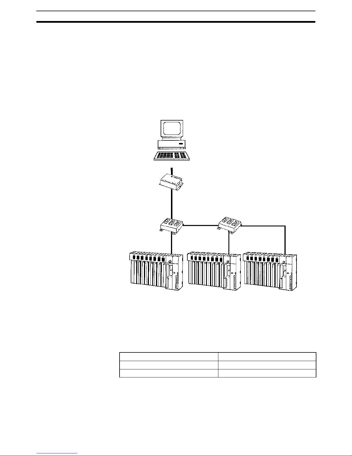
1-2-2 RS-422
RS-422 lines can be used to connected up to 32 PCs to the same host computer .
Transmission Distance The maximum transmission distance varies with the method in which a host
computer and PCs are connected. There are two connection methods available:
via RS-232C wire cable and via optical fiber cable. Either method requires the
use of Link Adapters. The overall arrangement of system components is the
same regardless of whether wire or optical fiber cable is used. A system with
wire components is shown below. Refer to Appendix B Specifications for Link
Adapters specifications.
Host computer (mainframe, personal
computer, or mini-computer)
RS-232C
(15 m max.)
3G2A9-AL004-(P)E
Link Adapter
3G2A9-AL001
Link Adapter
RS-422
(trunk line)
RS-422 (trunk line)
Branch
RS-422 (10 m max.)
Branch
RS-422 (10 m max.)
CV-series PC CV-series PC CV-series PC
3G2A9-AL001
Link Adapter
RS-422 (trunk line)
RS-422 Cable The host computer can be connected to up to 32 PCs through RS-422 wire
cables. If the host computer has a RS-422 port, it can be connected directly to
the first 3G2A9-AL001 Link Adapter. If the host computer has only a RS-232C
port, use a 3G2A9-AL004-E or 3G2A9-AL004-PE Link Adapter to convert
RS-232C to RS-422 as shown above. The maximum cable lengths are as follows:
Length of RS-232C cable
15 m max.
Total length of RS-422 cable 500 m max.
Length of each RS-422 branch 10 m max.
Optical Fiber Cable The 3G2A9-AL004-E or 3G2A9-AL004-PE and 3G2A9-AL002-E or
3G2A9-AL002-PE Link Adapters can be used to connect a Host Link System
using optical fiber cables. The 3G2A9-AL004-E or 3G2A9-AL004-PE Link
Adapters are used to convert between wire and optical lines and the
3G2A9-AL002-E or 3G2A9-AL002-PE Link Adapters are used to branch optical
lines. In the diagram shown above, the AL001 Link Adapters would be replaced
System Configuration Section 1-2
Page 15
8
with 3G2A9-AL002-E or 3G2A9-AL002-PE Link Adapters, the 3G2A9-AL004-E
or 3G2A9-AL004-PE Link Adapter would be replaced with a 3G2A9-AL004-E or
3G2A9-AL004-PE Link Adapter and then 3G2A9-AL004-E or
3G2A9-AL004-PE Link Adapters would be inserted before each PC to convert
back to wire cable. The maximum transmission distance varies with the Link
Adapter and the kind of optical fiber cable as follows:
Cable 3G2A9-AL002-PE
3G2A9-AL004-PE
3G2A9-AL002-E
3G2A9-AL004-E
APF 20 m Connection impossible
PCF 200 m 800 m
APF: all-plastic fiber; PCF: plastic-clad fiber
1-3 Communications Specifications
The specifications of the host interface on the PC’s CPU are as follows:
Communications method Four-wire, half duplex
Synchronization method Start-stop, 1 or 2 stop bits (set in PC Setup)
Baud rate 1200/2400/4800/9600/19200 bps (set in PC Setup)
Transmitted code 7- or 8-bit ASCII (set in PC Setup)
Error detection Vertical parity, even/odd (set in PC Setup)
Interface RS-232C/RS-422 (set on selector on CPU)
Transmission distance RS-232C: 15 m max.; RS-422: 500 m total max.
(See details under System Configuration.)
The following are the communications specifications of the Host Link Unit. (The
general specifications of the Host Link Unit are the same as those of the CV-series PCs.)
Item Port 1 Port 2
Interface RS-232C RS-232C or RS-422 (selectable)
Communications method Half duplex or full duplex; Set in CPU Bus
Unit System Setup.
RS-232C: Half duplex or full duplex; Set in
CPU Bus Unit System Setup.
RS-422: Full duplex
Synchronization method Start-stop, 1 or 2 stop bits; Set in CPU Bus
Unit System Setup.
Start-stop, 1 or 2 stop bits; Set in CPU Bus
Unit System Setup.
Baud rate 1200, 2400, 4800, 9600, or 19200 bps; Set
in CPU Bus Unit System Setup.
1200, 2400, 4800, 9600, or 19200 bps; Set
in CPU Bus Unit System Setup.
Transmitted code 7- or 8-bit ASCII; Set in CPU Bus Unit
System Setup.
7- or 8-bit ASCII; Set in CPU Bus Unit
System Setup.
Error detection Vertical parity, even/odd/none; Set in CPU
Bus Unit System Setup. FCS (frame
checksum sequence)
Vertical parity, even/odd/none; Set in CPU
Bus Unit System Setup. FCS (frame
checksum sequence)
Transmission control Xon/Xoff control; Set in CPU Bus Unit
System Setup.
Xon/Xoff control; Set in CPU Bus Unit
System Setup.
Transmission distance 15 m max. RS-232C: 15 m max.;
RS-422: 500 m total max.
Communications Specifications Section 1-3
Page 16
9
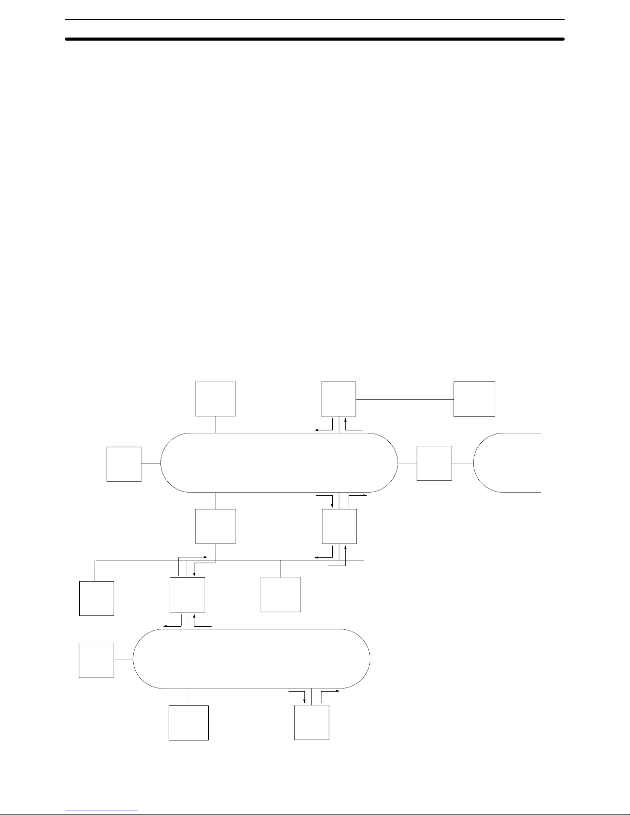
1-4 Gateway Function
A host computer in a Host Link System can communicate with CV-series PCs or
IBM PC/AT or compatible computers on other networks through the Host Link
System. Communications are possible to up to two networks away from the local
Host Link System (three including the local Host Link System). The PC must belong to a SYSMAC LINK or SYSMAC NET Link System to use the gateway function. The gateway function is actually a feature of the SYSMAC LINK and SYSMAC NET Link Systems and is not possible unless a SYSMAC LINK and/or
SYSMAC NET Link Unit is mounted to at least one of the PCs in the Host Link
System.
In the following example, the host computer connected to the Host Link System
can communicate with the PCs in the SYSMAC LINK System and the SYSMAC
NET Link Systems. The numbers in parentheses indicate the various networks
through which communications can move.
Although either CV - or C-mode commands can be used to control the PCs in the
local Host Link System, only CV-mode commands (FINS commands) can be
used to control the PCs in other Systems.
Refer to the SYSMAC LINK System Manual or the SYSMAC NET Link System
Manual for details on the gateway function. Refer to FINS Command Reference
Manual for details on sending commands to PCs on remote networks.
FA
computer
PC
PC
FA
computer
SYSMAC NET Link System
PC
SYSMAC NET Link System
PC
PC
PC
FA
computer
PC
FA
computer
Host computer
SYSMAC NET
Link System
SYSMAC LINK System
Host Link System
(1)
(2)
(3)
(4)
(5)
(7)(6)
(8)
(9)
(10)
(11)
(12)
Bridge
Gateway Function Section 1-4
Page 17

11
SECTION 2
Switch Settings and Communications Parameters
This section provides information on setting the switches that control communications parameters for the CPU. These
switches can be also be set to use the communications parameters specified in the PC Setup in the CPU. In addition, this section provides information on the Host Link Unit switches setting and CPU Bus Unit System Setup parameters that control
communications.
2-1 CPU Settings and Parameters 12. . . . . . . . . . . . . . . . . . . . . . . . . . . . . . . . . . . . . . . . . . . . . . . .
2-1-1 Interface-related Components on CPU 12. . . . . . . . . . . . . . . . . . . . . . . . . . . . . . . . .
2-1-2 Communications Parameters in PC Setup 13. . . . . . . . . . . . . . . . . . . . . . . . . . . . . . .
2-2 Host Link Unit Settings and Parameters 13. . . . . . . . . . . . . . . . . . . . . . . . . . . . . . . . . . . . . . .
2-2-1 Host Link Unit Setting Procedure 13. . . . . . . . . . . . . . . . . . . . . . . . . . . . . . . . . . . . .
2-2-2 Host Link Unit Components 14. . . . . . . . . . . . . . . . . . . . . . . . . . . . . . . . . . . . . . . . .
2-2-3 CPU Bus Unit System Setup 18. . . . . . . . . . . . . . . . . . . . . . . . . . . . . . . . . . . . . . . . .
Page 18
12
2-1 CPU Settings and Parameters
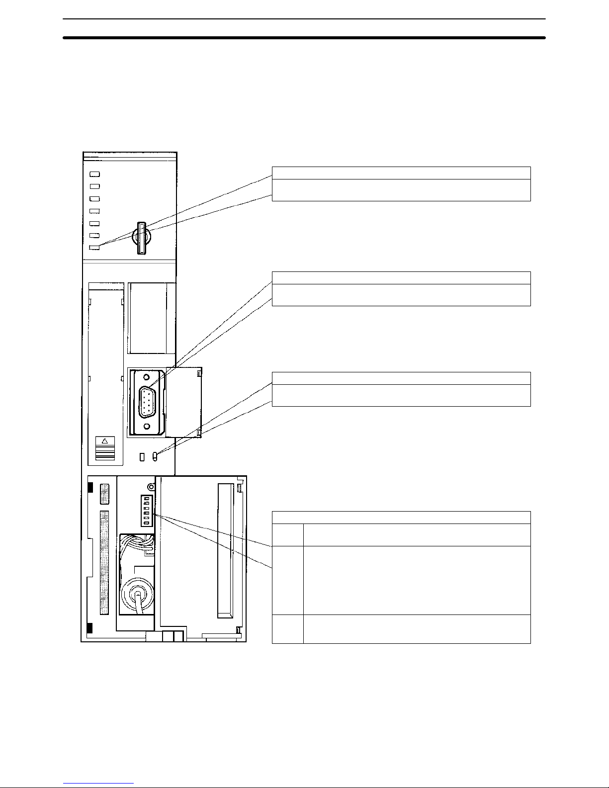
2-1-1 Interface-related Components on CPU
The following illustration shows the various parts of a CV-series CPU that are
related to a Host Link System. Details on the operation of these parts are provided later in the manual.
HOST LINK
RS-422
RS-232C
COMM (communications) indicator (Orange)
Lit when data is being transferred or received via the host interface.
Host interface port
Connected to RS-232C or RS-422 connector.
Transmission path selector
Set to RS-232C for RS-232C communications.
Set to RS-422 for RS-422 communications.
DIP switch
Pin 6 ON: Connects termination resistance for RS-422.
OFF: Disconnects termination resistance for RS-422.
Pin 4 ON: Sets the following communications parameters:
Baud rate: 9,600 bps
Unit number: 0
Parity: Even
Data length: 7 bits
Stop bits: 2
OFF: Sets communications parameters from the PC Setup.
Pin 3 ON: Enables connection to PT via host link connector.
OFF: Enable connection to host link via host link connector.
(see
note
1)
Note 1. The ON conditions of the communications settings (pin 4) shown above ap-
ply to CPUs with a lot number of “jj75” or greater (manufactured in and
after July 1995.) The settings for those with a lot number of “jj65” or smaller (manufactured in and before June 1995) are as follows:
Stop Bits: 1
Baud Rate: 2400 bps
CPU Settings and Parameters Section 2-1
Page 19

13
2. The cable connecting to the host interface is not available from OMRON.
Refer to Section 3 Installation and prepare an appropriate cable.
3. For setting the termination resistance of the pin 6, refer to Section 3 Installa-
tion.
4. The cable connecting the Optical Interface and the connector on the PC (for
conversion between 25 pins and 9 pins) is not available from OMRON.
2-1-2 Communications Parameters in PC Setup
If pin 4 of the DIP switch on the CPU is turned OFF, the communications parameters for the host interface will be set according to the PC Setup contained in the
CPU. The PC Setup is set from a Peripheral Device, such as the CVSS, and can
be either set offline and then transferred to the CPU or can be set online.
The following parameters can be set. The default setting of each parameter is
shown. These defaults are different from those used if pin 4 is turned ON, i.e.,
you can select either the pin 4 defaults or the defaults listed below to achieve
different settings without specifying them individually. Refer to the CVSS operation manuals for details on changing settings in the PC Setup.
Parameters Possible settings Default
Baud rate 1200, 2400, 4800, 9600, or 19200 bps 9600 bps
Stop bits Either 1 or 2 stop bits 2 stop bits
Parity Even, odd, or no parity Even parity
Data length
(Data bits)
Either 7-bit or 8-bit data 7-bit data
Unit number* 00 to 31 (Used by host computer to identify PCs.) 00
Note *The unit number of the host interface corresponds to the node number of Host
Link Units.
2-2 Host Link Unit Settings and Parameters
2-2-1 Host Link Unit Setting Procedure
Use the following setting procedure for each Unit.
1, 2, 3... 1. Design the system, including the devices to be connected and the connec-
tion methods, referring to Section 1 Introduction.
2. Prepare cables referring to Section 3 Installation.
3. Set Host Link Unit switches referring to 2-2-2 Host Link Unit Setting.
4. Set the CPU Bus Unit System Setup referring to 2-2-3 CPU Bus Unit System
Setup and the CVSS Operation Manual: Online.
5. Connect the system referring to Section 3 Installation.
6. Test communications referring to Section 4 Communications.
7. Operate the system for final checking.
Host Link Unit Settings and Parameters Section 2-2
Page 20
14
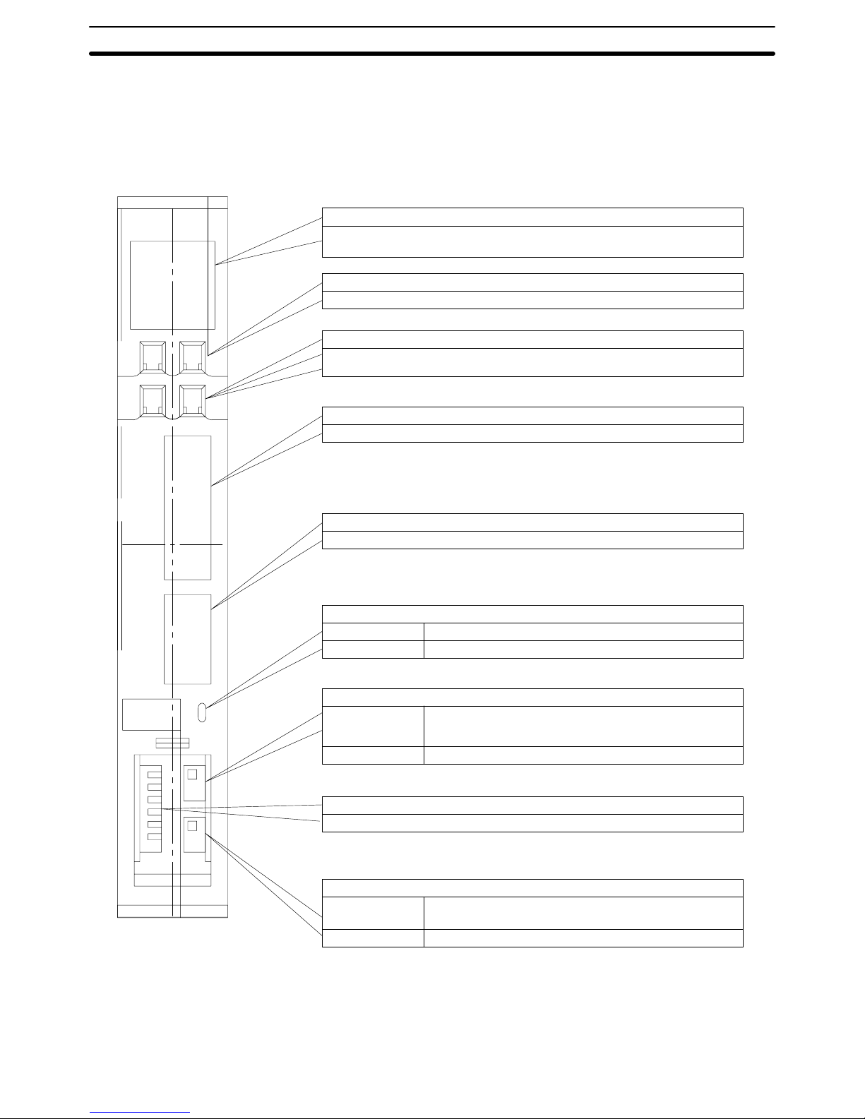
2-2-2 Host Link Unit Components
The following illustration shows the components of the Host Link Unit.
Unit
No.
X10
1
X10
0
X10
1
X10
0
PORT1
RS-232C
PORT2
RS-232C
RS-422
RS-232C
RS-422
Indicators
It is possible to monitor the working condition of the Host Link Unit with these
indicators.
Unit number switch
The unit number is set with this decimal rotary switch.
Node number switch
The node number at communications port 2 is set with this decimal rotary
switch.
Communications port 1 (RS-232C only, 25 pins)
Connects to an RS-232C cable.
Communications port 2 (RS-232C/RS-422 selectable, 9 pins)
Connects to an RS-232C or RS-422 cable.
Communications path selector
Top Selects RS-232C for communications port 2.
Bottom Selects RS-422 for communications port 2.
5-V output switch
Top 5 V, which is used if the optical interface is connected to
communications port 1, is supplied to pin number 14 of
communications port 1.
Bottom 5 V is not supplied to communications port 1.
DIP switch
Basic operations of the Unit are set here.
Terminator switch
Top Connects termination resistance for RS-422
communications.
Bottom Disconnects termination resistance.
Note Cables for the connectors (ports 1 and 2) are not available from OMRON.
Host Link Unit Settings and Parameters Section 2-2
Page 21
15
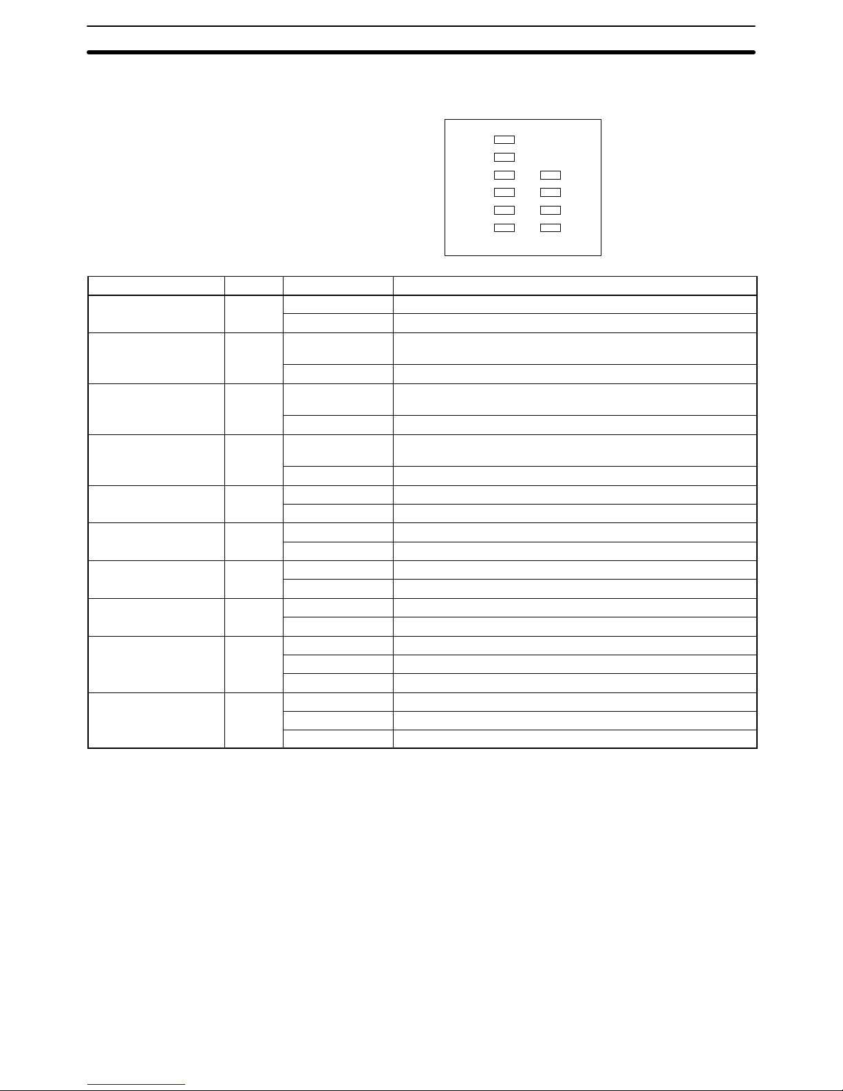
Indicators The status of the Host Link Unit can be determined using the status of the indica-
tors on the Host Link Unit.
RUN
ERH
ERC1
SD1
RD1
TS1
ERC2
SD2
RD2
TS2
Indicator Color Status Meaning
RUN Green Lit The Host Link Unit is normal.
Not lit The Host Link Unit has an error.
ERH (PC error) Red Lit The PC has an error or either the unit number setting or I/O
table is wrong.
Not lit The PC is normal.
ERC1 (transmission
error 1)
Red Lit Communications port 1 has a transmission error (parity, framing,
FCS, or overrun error).
Not lit Communications port 1 is normal.
ERC2 (transmission
error 2)
Red Lit Communications port 2 has a transmission error (parity, framing,
FCS, or overrun error) or the node number setting is wrong.
Not lit Communications port 2 is normal.
SD1 (send 1) Orange Lit Data is being transmitted from communications port 1.
Not lit No data is being transmitted from communications port 1.
SD2 (send 2) Orange Lit Data is being transmitted from communications port 2.
Not lit No data is being transmitted from communications port 2.
RD1 (receive 1) Orange Lit Data is being received at communications port 1.
Not lit No data is being received at communications port 1.
RD2 (receive 2) Orange Lit Data is being received at communications port 2.
Not lit No data is being received at communications port 2.
TS1 (test 1) Orange Lit A wrap test is being executed at communications port 1.
Flashing A wrap test at communications port 1 has been completed.
Not lit No wrap test is being executed at port 1.
TS2 (test 2) Orange Lit A wrap test is being executed at communications port 2.
Flashing A wrap test at communications port 2 has been completed.
Not lit No wrap test is being executed at port 2.
Host Link Unit Settings and Parameters Section 2-2
Page 22
16
Rotary Switch Settings
The Host Link Unit provides rotary switches on the front panel used to set the
Host Link Unit’s unit number and node number for identification in the Host Link
System. Set the rotary switches only when the PC is turned off.
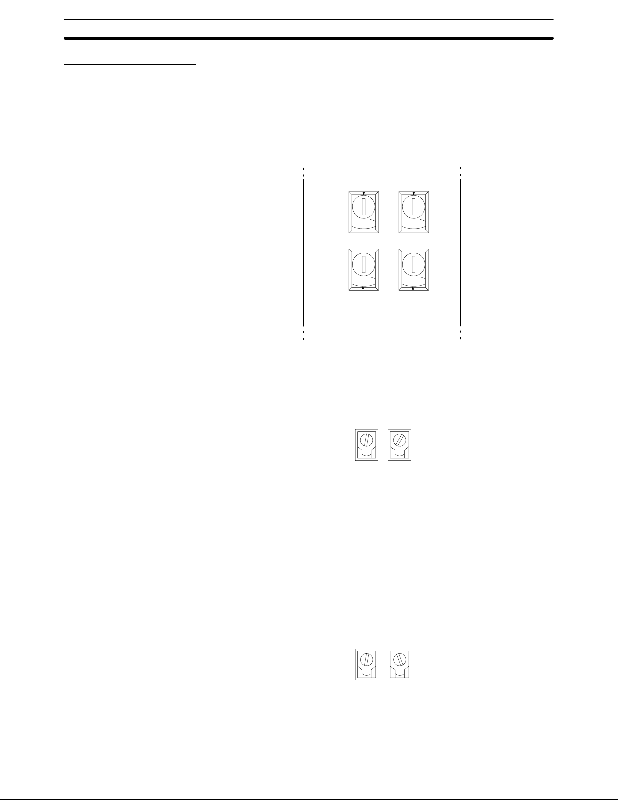
Location of Rotary Switches The rotary switches are located beneath the indicators and appear as shown in
the following illustration. SW1 and SW2 are used to set the Host Link Unit’s unit
number as a CPU Bus Unit; SW3 and SW4 are used to set the node number for
the Host Link Unit’s communications port 2.
0
NODE
No.
X10
1
0
0
UNIT
No.
X10
1
0
SW1 SW2
SW3 SW4
X10
0
X10
0
Set the unit number to a unique number between 0 and 15 in the decimal. This is
the unit number of the Host Link Unit as a CPU Bus Unit. Do not use the same
number on two CPU Bus Units in the same PC.
Set the 10’s digit of the unit number with SW1 and the 1’s digit with SW2. In the
following example, the unit number is set to 12.
1
UNIT
No.
X10
1
SW1
2
X10
0
SW2
Note 1. The node number must not be larger than 15. If a node number larger than
15 is set, an error will result and the ERH indicator on the display panel will
light.
2. Each CPU Bus Unit for a PC must have a unique unit number.
If more than one PC is connected to a host computer (e.g., one via the CPU’s
host interface and one via the Host Link Unit), each link is identified by a node
number. The node number of port 2 is set here. The node number of communications port 1 is fixed to 00.
Set a node number between 0 and 31 in decimal. Set the 10’s digit of a node
number with SW3 and the 1’s digit with SW4. In the following example, the node
number of the Host Link Unit is set to 29.
2
NODE
No.
X10
1
SW3
9
X10
0
SW4
Note 1. The node number must not be larger than 31. If a node number larger than
31 is set, an error will result and the ERC2 indicator on the display panel will
light.
Unit Number (SW1 and
SW2)
Node Number of
Communications Port 2
(SW3 and SW4)
Host Link Unit Settings and Parameters Section 2-2
Page 23
17
2. Each node number must be unique in the same Host Link System.
3. The node number of the Host Link Unit’s communications port 1 is fixed to
00.
4. The node number of the CPU’s host interface is set in the PC Setup. (In the
PC Setup, the node number of the host interface is called the “unit #.”)
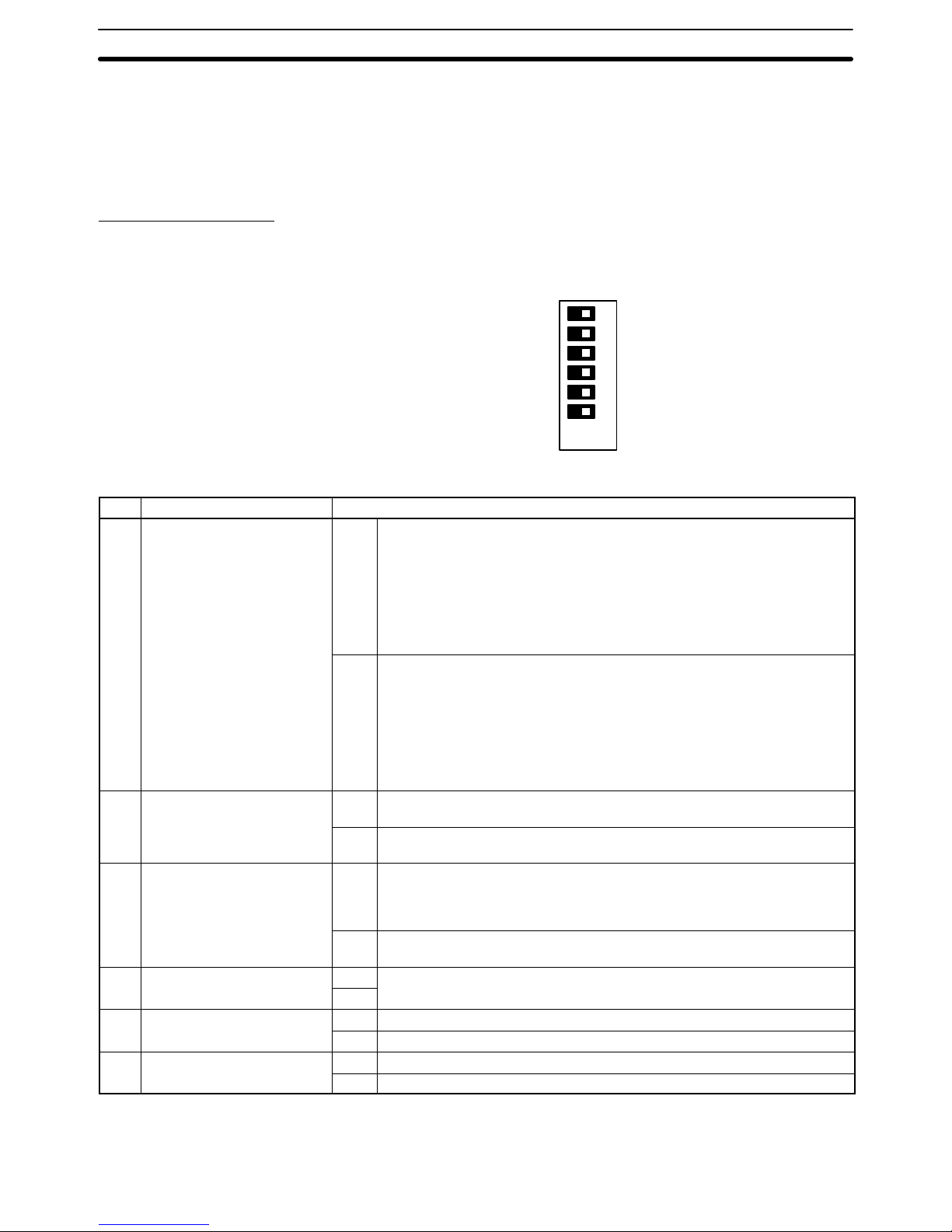
DIP Switch Settings
Pins 1 through 6 on Host Link Unit’s DIP switch are used to control certain communications parameters and tests. These pins are turned ON when they are slid
to the left and turned OFF when they are slid to the right.
ON
6
4
3
2
1
5
OFF
The following settings are possible with the DIP switch.
Pin Function Setting
1 Communications parameters
for communications ports 1
and 2 (see note)
ON Sets the following communications conditions for communications ports 1
and 2.
Baud rate: 9,600 bps
Stop bits: 2
Parity: Even number
Data length: 7 bits
Xon/Xoff control: Not executed
Communications method: Full duplex
OFF Executes the Host Link Unit’s communication using the values in the PC’s
CPU Bus Unit System Setup. The following are default values:
Baud rate: 9,600 bps
Stop bits: 2
Parity: Even number
Data length: 7 bits
Xon/Xoff control: Not executed
Communications method: Full duplex
2 CTS control for
communications port 1
ON Turns ON (sets to 0 V) the CTS signal (clear to send). This pin must be
turned ON if the Host Link Unit is connected to a host computer.
OFF Receives an external signal for CTS. This switch must be turned OFF while
a wrap communications test is being executed.
3 CTS control for
communications port 2
ON Turns ON (sets to 0 V) the CTS signal (possible to receive). This pin must
be turned ON if the Host Link Unit is connected to a host computer via an
RS-232C cable. This pin, however, need not be turned ON if the Host Link
Unit is connected to a host computer via an RS-422 cable.
OFF Receives an external signal for CTS. This switch must be turned OFF while
a wrap communications test is being executed.
4 Not used ON Always turn OFF.
OFF
5 Wrap communications test ON Executes a wrap communications test.
OFF Enables normal Host Link Unit operation.
6 Test port designation ON Designates port 2 for the wrap communications test.
OFF Designates port 1 for the wrap communications test.
Note The ON conditions of the communications settings (pin 1) shown above apply to
CPUs with a lot number of “jj75” or greater (manufactured in and after July
Host Link Unit Settings and Parameters Section 2-2
Page 24

18
1995.) The settings for those with a lot number of “ jj65” or smaller (manufactured in and before June 1995) are as follows:
Stop Bits: 1
Baud Rate: 2400 bps.
Switch Setting Procedure
The setting procedure for the DIP switch is as follows for port 1 (25 pins):
1, 2, 3... 1. Turn OFF pin number 1 to specify use of the parameters in the CPU System
Setup. Unless these parameters have been changed, the default values will
be set.
2. Turn ON DIP switch pin 2. When this is done, the RS and CS pins of the connector need not be short-circuited.
3. Make sure that pin 4 is OFF.
4. Turn OFF pin 5 to set normal operations. This pin is turned ON only when
performing a wrap communications test.
5. Turn ON the 5-V output switch if an optical interface is going to be used. This
switch should be turned ON only after connecting the optical interface.
or Turn OFF the 5-V output switch if an optical interface is not going to be used.
The setting procedure for the DIP switch is as follows for port 2 (9 pins):
1, 2, 3... 1. Specify either RS-232C or RS-422 communications.
2. If RS-232C communications are specified, turn ON DIP switch pin 3. When
this is done, the RS and CS pins of the connector need not be short-circuited.
or If RS-422 communications are specified, turn ON the terminator switch at
the last Unit on the RS-422 communications line.
3. Turn OFF pin number 1 to specify use of the parameters in the CPU System
Setup. Unless these parameters have been changed, the default values will
be set.
4. Make sure that pin 4 is OFF.
5. Turn OFF pin 5 to set normal operations. This pin is turned ON only when
performing a wrap communications test.
6. Turn ON the 5-V output switch if an optical interface is going to be used. This
switch should be turned on only after connecting the optical interface.
or Turn OFF the 5-V output switch if an optical interface is not going to be used.
2-2-3 CPU Bus Unit System Setup
Settings for the Host Link Unit are made in the CPU Bus Unit’s System Setup.
The CPU Bus Unit’s System Setup parameters are set from the CVSS (CV Support Software) and supported by version 2 of the CVSS [CV500-ZS3AT1-EV2
(3.5” disks), CV500-ZS5AT1-EV2 (5.25” disks)].
Setting Procedure The system settings of the Host Link Unit are explained below. For details, refer
to the CVSS Operation Manual: Online.
1, 2, 3... 1. Set the rotary switches on the Host Link Unit (refer to page 16).
2. Mount the Host Link Unit to the PC and turn ON the PC (refer to Section 3
Installation).
3. Start the CVSS and switch to online mode.
4. Create the I/O table.
Switch Settings for
Communications Port 1
Switch Settings for
Communications Port 2
Host Link Unit Settings and Parameters Section 2-2
Page 25
19
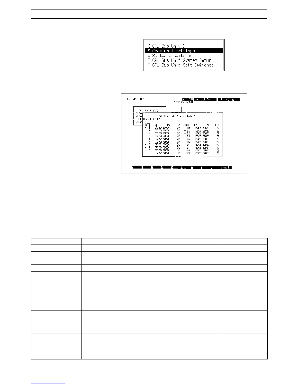
5. Select “CPU Bus Setting.” The following menu will be displayed.
6. Select “CPU Bus Unit System Setup.” The following screen will appear.
7. Press F10 and then input the unit number of the Host Link Unit. The default
value will be displayed if no other value has been input.
8. Refer to the table below for the settings. These settings are made by turning
ON and OFF the bits in the various bits of the System Setup. These bytes
and how they correspond to the various settings are described following the
table.
9. To make the settings effective, turn the PC OFF and ON or restart the Host
Link Unit.
Item Setting Default
Baud rate 1200, 2400, 4800, 9600, or 19200 bps 9600 bps
Stop bits 1 stop bit or 2 stop bits 2 stop bits
Parity Even number, odd number, or nil Even number
Data length 7- or 8-bit ASCII 7-bit ASCII
Xon/Xoff control Execute or not execute (effective only when the Host Link Unit is in
full duplex communications mode)
Not execute
Communications
method
Full duplex or half duplex (The half duplex system is effective only
when an RS-232C cable is used for communication.)
Full duplex
Retries Set to retry or not to retry. If retries are specified, the Host Link Unit
will attempt to transmit again when a data transmission is
interrupted.
No retries
Transmission stop code
(Xoff)
This setting is effective only when Xon/Xoff control is used. 13 (hexadecimal)
Transmission stop
cancel code (Xon)
This setting is effective only when Xon/Xoff control is used. 11 (hexadecimal)
Transmission delay
time
The interval between the RS signal is ON and data transmission is
done with this setting. The setting is effective in half duplex
communications mode only. The setting range is 0 to 510 ms (255 x
2 ) with 2-ms increments. If 0 ms is set, data will be transmitted
within 1 ms after the RS signal is ON.
0 ms
Host Link Unit Settings and Parameters Section 2-2
Page 26
20
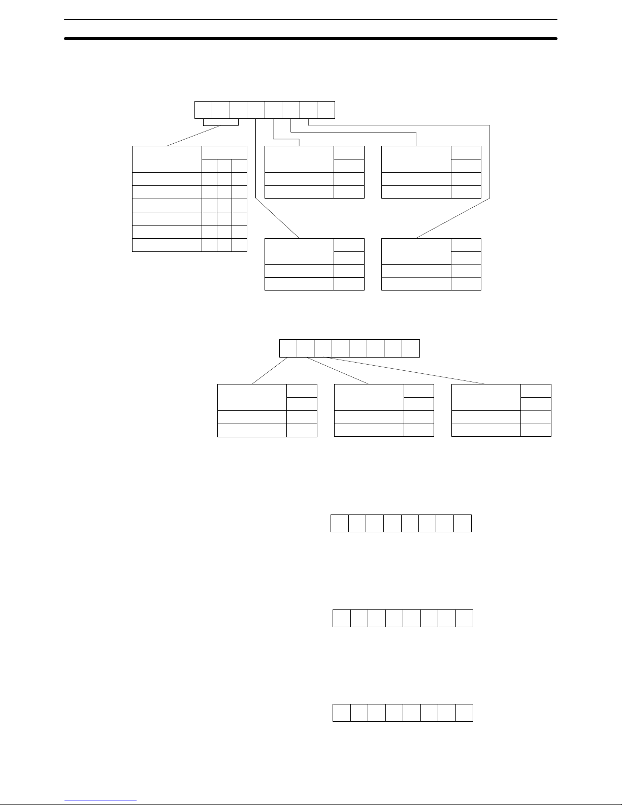
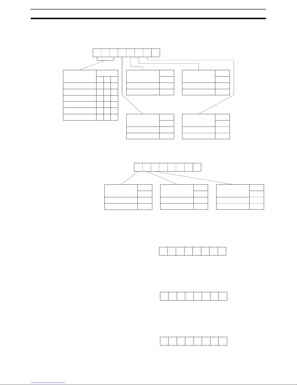
The setting of communications port 1 are as follows:
7
Bit
Baud rate
9600 bps
1200 bps
2400 bps
4800 bps
9600 bps
19200 bps
65
000
001
010
011
100
101
3
Bit
Parity
Yes
No
0
1
2
Bit
Parity
Even number
Odd number
0
1
4
Bit
Stop bits
2 bits
1 bit
0
1
1
Bit
Data length
7 bits
8 bits
0
1
0
76543210
Bit
+0 byte
7
Bit
Xon/Xoff control
Not executed
Executed
0
1
6
Bit
Communications
mode
Full duplex
Half duplex
0
1
5
Bit
Retries
No
Yes
0
1
00000
76543210
Bit
+1 byte
Set the Xoff (transmission stop) code in the +2 byte. The default is 13 hexadecimal and its bit string is as follows: 13 = 00010011
76543210
Bit
+2 byte
Set the Xon (transmission stop cancel) code in the +3 byte. The default is 11 hexadecimal and its bit string is as follows: 11 = 00010001
76543210
+3 byte
Bit
Set the transmission delay time in the +4 byte. The default is 0 ms and its bit
string is as follows: 00 = 00000000
76543210
+4 byte
Bit
Set the +5 to +9 bytes to 0.
Settings for
Communications Port 1
Host Link Unit Settings and Parameters Section 2-2
Page 27
21
The setting of communications port 2 is as follows:
7
Bit
Baud rate
9600 bps
1200 bps
2400 bps
4800 bps
9600 bps
19200 bps
65
000
001
010
011
100
101
3
Bit
Parity
Yes
No
0
1
2
Bit
Parity
Even number
Odd number
0
1
4
Bit
Stop bits
2 bits
1 bit
0
1
1
Bit
Data length
7 bits
8 bits
0
1
0
76543210
Bit
+10 byte
7
Bit
Xon/Xoff control
Not executed
Executed
0
1
6
Bit
Communications
mode
Full duplex
Half duplex
0
1
5
Bit
Re-transmission
No
Yes
0
1
00000
76543210
+11 byte
Bit
Set the Xoff (transmission stop) code in the +12 byte. The default is 13 hexadecimal and its bit string is as follows: 13 = 00010011
76543210
Bit
+12 byte
Set the Xon (transmission stop cancel) code in the +13 byte. The default is 11
hexadecimal and its bit string is as follows: 11 = 00010001
76543210
+13 byte
Bit
Set the transmission delay time in the +14 byte. The default is 0 ms and its bit
string is as follows: 00 = 00000000
76543210
+14 byte
Bit
Set the +5 to +9 bytes to 0.
Setting of Communications
Port 2
Host Link Unit Settings and Parameters Section 2-2
Page 28

22
Use the following procedure to set the CPU Bus Unit System Setup for the Host
Link Unit.
1, 2, 3... 1. Set the baud rate, number of stop bits, parity, and data length as required.
2. If connecting to a Programmable Terminal, specify full duplex communications and turn OFF Xon/Xoff control. No other settings are required for connection to a Programmable Terminal.
or If connecting to a host computer and commands will not be sent from the
Host Link U n i t t o t h e host computer, set full duplex communications and turn
OFF Xon/Xoff control. No other settings are required
or If connecting to a host computer and commands will be sent from the Host
Link Unit to the host computer, determine whether full- or half-duplex communications are required and continue to the next step.
3. If full-duplex communications are to be used, set Xon/Xoff control are required. This is the last setting that is required.
or If half-duplex communications are to be used, set the transmission delay
time.
4. Set whether or not retries are to be made.
Host Link Unit System
Setting Procedure
Host Link Unit Settings and Parameters Section 2-2
Page 29
23
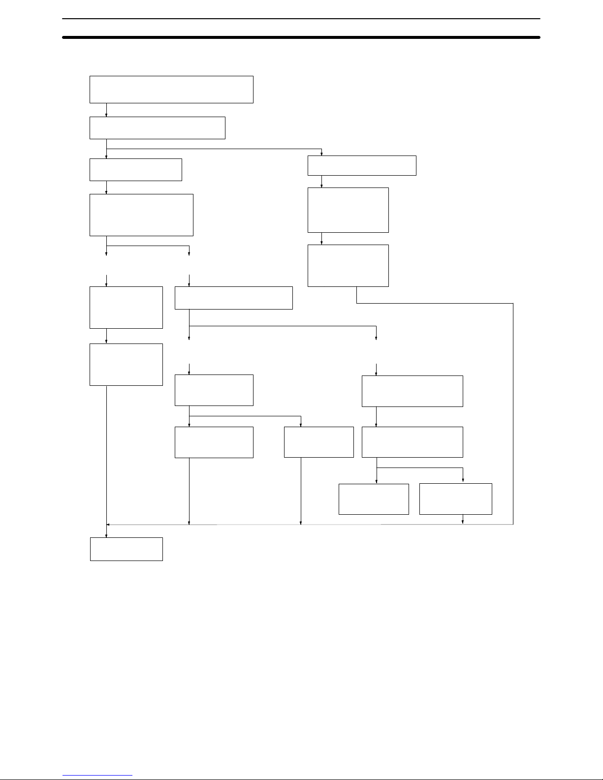
The following flowcharts illustrates the above procedure.
Half
duplex
What is to be connected?
Host computer
Does the Host Link Unit
send commands to the
host computer?
No Yes
Specify full duplex communications.
Specify the communications
method.
Set so that no
Xon/Xoff control
will be executed.
Full
duplex
Is Xon/Xoff control
to be executed?
Set so that no
Xon/Xoff control
will be executed.
Set so that no
Xon/Xoff control
will be executed.
Programmable Terminal
Set so that no
Xon/Xoff control
will be executed.
Set the transmission
delay time.
Are data retries to be used
for transmission failures?
Set so that there
will be no data
re-transmission.
Set so that there
will be data retransmission.
Set the baud rate, number of stop bits, parity, and data length.
End
Select the full duplex
communications
method.
(See note 1)
(See note 1)
(See note 2)
Note 1. Specify full-duplex communications method and turn OFF the Xon/Xoff con-
trol in the following cases:
• If the Host Link Unit is connected to a host computer and no commands will
be sent from the Host Link Unit to the host computer.
• If a PC is connected.
In the above cases, actual communications control is executed in half du-
plex even though the full duplex communications are specified. If the Host
Link Unit is used simultaneously with the CPU’s host interface, full-duplex
communications must be specified to enable normal communications.
2. Only full-duplex communications are possible for RS-422 communications
at communications port 2.
Host Link Unit Settings and Parameters Section 2-2
Page 30

25
SECTION 3
Installation
This section describes how to connect the Host Link Unit, host link interfaces, Link Adapters, and host computer. Refer to
Section 1 Intr oduction for details on the system configuration. Refer to the CV-series PC Installation Guide for general installation procedures and precautions.
3-1 Host Link Unit Dimensions 26. . . . . . . . . . . . . . . . . . . . . . . . . . . . . . . . . . . . . . . . . . . . . . . . .
3-2 Mounting the Host Link Unit 27. . . . . . . . . . . . . . . . . . . . . . . . . . . . . . . . . . . . . . . . . . . . . . . .
3-3 Connection Cables for the Host Link Unit 27. . . . . . . . . . . . . . . . . . . . . . . . . . . . . . . . . . . . . .
3-4 RS-232C Connections 28. . . . . . . . . . . . . . . . . . . . . . . . . . . . . . . . . . . . . . . . . . . . . . . . . . . . .
3-4-1 CPU Connections 28. . . . . . . . . . . . . . . . . . . . . . . . . . . . . . . . . . . . . . . . . . . . . . . . . .
3-4-2 Host Link Unit Connections 29. . . . . . . . . . . . . . . . . . . . . . . . . . . . . . . . . . . . . . . . .
3-5 RS-422 Connections 31. . . . . . . . . . . . . . . . . . . . . . . . . . . . . . . . . . . . . . . . . . . . . . . . . . . . . . .
3-5-1 CPU Connections 31. . . . . . . . . . . . . . . . . . . . . . . . . . . . . . . . . . . . . . . . . . . . . . . . . .
3-5-2 Host Link Unit Connections 33. . . . . . . . . . . . . . . . . . . . . . . . . . . . . . . . . . . . . . . . .
3-6 1-to-1 Connection Examples 35. . . . . . . . . . . . . . . . . . . . . . . . . . . . . . . . . . . . . . . . . . . . . . . .
3-6-1 Host Link Unit Connection to Host Computer 35. . . . . . . . . . . . . . . . . . . . . . . . . . .
3-6-2 Host Link Unit Connection to PT 37. . . . . . . . . . . . . . . . . . . . . . . . . . . . . . . . . . . . .
3-7 Optical Interface Connections 38. . . . . . . . . . . . . . . . . . . . . . . . . . . . . . . . . . . . . . . . . . . . . . .
3-7-1 Required Devices 38. . . . . . . . . . . . . . . . . . . . . . . . . . . . . . . . . . . . . . . . . . . . . . . . . .
3-7-2 Connections to Optical Module 39. . . . . . . . . . . . . . . . . . . . . . . . . . . . . . . . . . . . . . .
3-8 1-to-N Connection Example 40. . . . . . . . . . . . . . . . . . . . . . . . . . . . . . . . . . . . . . . . . . . . . . . .
3-9 Wiring 42. . . . . . . . . . . . . . . . . . . . . . . . . . . . . . . . . . . . . . . . . . . . . . . . . . . . . . . . . . . . . . . . . .
3-9-1 Connecting the Shield to FG 42. . . . . . . . . . . . . . . . . . . . . . . . . . . . . . . . . . . . . . . . .
3-9-2 Not Connecting the Shield to FG 42. . . . . . . . . . . . . . . . . . . . . . . . . . . . . . . . . . . . . .
3-9-3 Soldering 43. . . . . . . . . . . . . . . . . . . . . . . . . . . . . . . . . . . . . . . . . . . . . . . . . . . . . . . .
3-9-4 Hood Assembly 44. . . . . . . . . . . . . . . . . . . . . . . . . . . . . . . . . . . . . . . . . . . . . . . . . . .
3-9-5 Recommended Cables and Connectors 44. . . . . . . . . . . . . . . . . . . . . . . . . . . . . . . . .
3-9-6 Link Adapters 44. . . . . . . . . . . . . . . . . . . . . . . . . . . . . . . . . . . . . . . . . . . . . . . . . . . .
3-9-7 Cable Lengths 45. . . . . . . . . . . . . . . . . . . . . . . . . . . . . . . . . . . . . . . . . . . . . . . . . . . .
Page 31

26
3-1 Host Link Unit Dimensions
All dimensions are in millimeters in the following diagram of the CV500-LK201
Host Link Unit. For the CPU dimensions and general installation procedures,
refer to the CV-series PC Installation Guide.
34.5
250
93
105
95
Host Link Unit Dimensions Section 3-1
Page 32

27
3-2 Mounting the Host Link Unit
Mounting Position Up to four CV500-LK201 Host Link Units can be mounted to any of the slots on a
CV-series CPU Rack or Expansion CPU Rack except when the CVM1-BC103 or
CVM1-BC053 Backplane is used. On a CVM1-BC103 Backplane, Host Link
Units must be mounted to the rightmost 6 slots; on a CVM1-BC053 Backplane,
the rightmost 3 slots.
3, 5, 6, or 10 slots
CPU Rack
The slots that Host Link Units can be mounted to varies with the
model of CPU Backplane as follows:
CV500-BC031: Any slots (3 slots total)
CV500-BC051: Any slots (5 slots total)
CV500-BC101: Any slots (10 slots total)
CVM1-BC103: Rightmost 6 slots only
CVM1-BC053: Rightmost 3 slots only
Expansion CPU Rack
It is possible to mount Host Link Units to any of the 11 slots.
(An Expansion CPU Rack cannot be connected to a CPU
Rack using a CVM1-BC053/103 Backplane.)
Expansion I/O Rack
Host Link Units can not be mounted to an Expansion I/O Rack.
PS: Power supply
CPU: Central Processing Unit
IOC: I/O Control Unit
IOIF: I/O Interface Unit
11 slots
PS
IOIF
PS
IOC
PS
IOIF
CPU
The maximum current consumption of the Host Link Unit is 600 mA if an optical
interface is not used. If 5 V is supplied when using an optical interface, however,
the current consumption increases by 100 mA. When using the Host Link Unit
with other Units, make sure that the actual current consumption of the Host Link
Unit does not exceed the total permissible current consumption (refer to the CV-
series PC Installation Guide for details).
The Host Link Unit weighs 550 g maximum.
3-3 Connection Cables for the Host Link Unit
Basic cable wiring procedures are described in 3-9 Wiring. Details and examples are provided in the remaining subsections of Section 3.
Port 1 supports only RS-232C connections, which are described in the next subsection.
To connect to a Programmable Terminal (PT), you will need to prepare a cable
according to the information on page 37.
Current Consumption and
Weight
Communications Port 1
Connection Cable
Connection Cables for the Host Link Unit Section 3-3
Page 33

28
To connect to a host computer, you will need to prepare a full-duplex or half-duplex cable according to the information starting on page 35.
Port 1 supports either RS-232C or RS-422 connections. RS-232C connections
are described in the next subsection and RS-422 connections are described beginning on page 31.
If you are going to use an optical interface via RS-232C, you will need to prepare
a 9-to-25 pin conversion cable according to the information in the section starting on page 38.
To connect to a Programmable Terminal (PT) via RS-232C, you will need to prepare a cable according to the information on page 37. To connect to a host computer, you will need to prepare a full-duplex or half-duplex cable according to the
information on page 35.
3-4 RS-232C Connections
3-4-1 CPU Connections
Specifications Electrical characteristics: Conforming to EIA RS-232C
Direction of signal: Viewed from the PC.
Maximum cable length: 15 m
Host interface pin
No.
Signal Symbol Direction of
signal
Connector hood Frame ground FG --9 Signal ground SG (GND) --2 Send data SD (TXD) Output
3 Receive data RD (RXD) Input
4 Request to send RS (RTS) Output
5 Clear to send CS (CTS) Input
5
1
9
6
Connection Method The following diagram shows the connections between the host computer and
the PC. When RS-232C cable is used, a host computer can be connected to only
one PC.
2SD
3RD
7SG
4RTS
5 CTS
20 DTR
6 DSR
2SD
3RD
4RTS
5 CTS
9SG
Computer PC
Female 25-pin
RS-232C connector
Male 9-pin
Recommended Cable The following cables are recommended for connecting the host computer and
PC. Other cables can be used if desired as long as they meet the required specifications.
Manufactured by Fujikura: UL2464 AWG28 x 5P IFS-RVV-SB (UL approved)
Manufactured by Hitachi: UL2464-SB 5P x AWG28 (UL approved)
Communications Port 2
Connection Cable
RS-232C Connections Section 3-4
Page 34

29
Note 1. Ground the FG terminals of both the PC and the host computer to a a resis-
tance of 100 Ω or less. For details refer to the CV-series PC Installation
Guide and your host computer manual.
2. The following Connector and Connector Hood (both OMRON) are provided
with the CPU.
Connector XM2A-0901
Connector hood XM2S-0911
Connection Example The following diagram shows connections between the PC and host computer.
Pin Signal Signal
Host interface (RS-232C) Computer interface (RS-232C)
Shield
9
5
4
3
2
FG
SD (TXD)
RD (RXD)
RS (RTD)
CS (CTS)
SG (GND)
FG
SD
RD
RS
CS
SG
Connector hood
Note 1. Connect the shield of the cable to the FG (connector hood) of the PC.
2. Pins 1, 6, and 8 on the PC are used when RS-422 is used. Leave them unconnected when RS-232C is used.
3-4-2 Host Link Unit Connections
The specifications for RS-232C connections to the Host Link Unit are described
in this subsection for ports 1 and 2. When RS-232C cable is used, a host computer can be connected to only one PC.
Communications Port 1 Electrical characteristics: Conforming to EIA RS-232C
Direction of signal: Viewed from the Host Link Unit.
Maximum cable length: 15 m
Host Link Unit
Signal Symbol Direction of signal
connector pin no.
Input Output
Connector hood Frame ground FG --- --1 Frame ground FG --- --2 Send data SD (TXD) No Yes
3 Receive data RD (RXD) Yes No
4 Request to send RS (RTS) No Yes
5 Clear to send CS (CTS) Yes No
RS-232C Connections Section 3-4
Page 35

30
Host Link Unit
connector pin no.
Direction of signalSymbolSignalHost Link Unit
connector pin no.
OutputInput
7 Signal ground SG (GND) --- --8 Detect carrier data CD (DCD) Yes No
14 5 V for optical
interface
5 V No Yes
20 Data terminal ready ER (DTR) No Yes
13
1
25
14
Communications Port 2 Electrical characteristics: Conforming to EIA RS-232C
Direction of signal: Viewed from the Host Link Unit.
Maximum cable length: 15 m
Host Link Unit
Signal Symbol Direction of signal
connector pin no.
Input Output
Connector hood Frame ground FG --- --2 Send data SD (TXD) No Yes
3 Receive data RD (RXD) Yes No
4 Request to send RS (RTS) No Yes
5 Clear to send CS (CTS) Yes No
7 Detect carrier data CD (DCD) Yes No
9 Signal ground SG (GND) No No
5
1
9
6
RS-232C Connections Section 3-4
Page 36

31
Line Connections The following diagram shows the connections between the host computer and
the Host Link Unit. When RS-232C cable is used, a host computer can be connected to only one PC.
9
2
3
4
5
7
Pin number
9-pin
Host
Link
Unit
Host computer
7
2
3
4
5
8
25-pin
Connector
hood 1
Connector
hood
SG
SD
RD
RS
CS
CD
FG
*1
SG
SD
RD
RS
CS
CD
FG
*2
Shield
Signal
Note 1. It is not necessary to connect these terminals before connecting the host
computer to the Host Link Unit as long as the CTS selector is turned ON.
2. The RS and CD terminals must be connected when connecting the host
computer to the Host Link Unit using half-duplex communications.
3. Ground the FG terminals of both the PC and the host computer to a a resistance of 100 Ω or less. For details refer to the CV-series PC Installation
Guide and your host computer manual.
4. Connect the Host Link Unit to the FG terminal of the host computer via the
shield wire.
3-5 RS-422 Connections
3-5-1 CPU Connections
Specifications Electrical characteristics: Conforming to EIA RS-422
Direction of signal connection: Viewed from the PC.
Maximum cable length: 500 m total
Host interface
pin No.
Signal Symbol Direction of signal
Connector hood Frame ground FG --1 Send data A SDA (SD–) Output
2 Send data B SDB (SD+) Output
6 Receive data A RDA (RD–) Input
8 Receive data B RDB (RD+) Input
4 Request to send RS Output
5 Clear to send CS Input
5
1
9
6
RS-422 Connections Section 3-5
Page 37

32
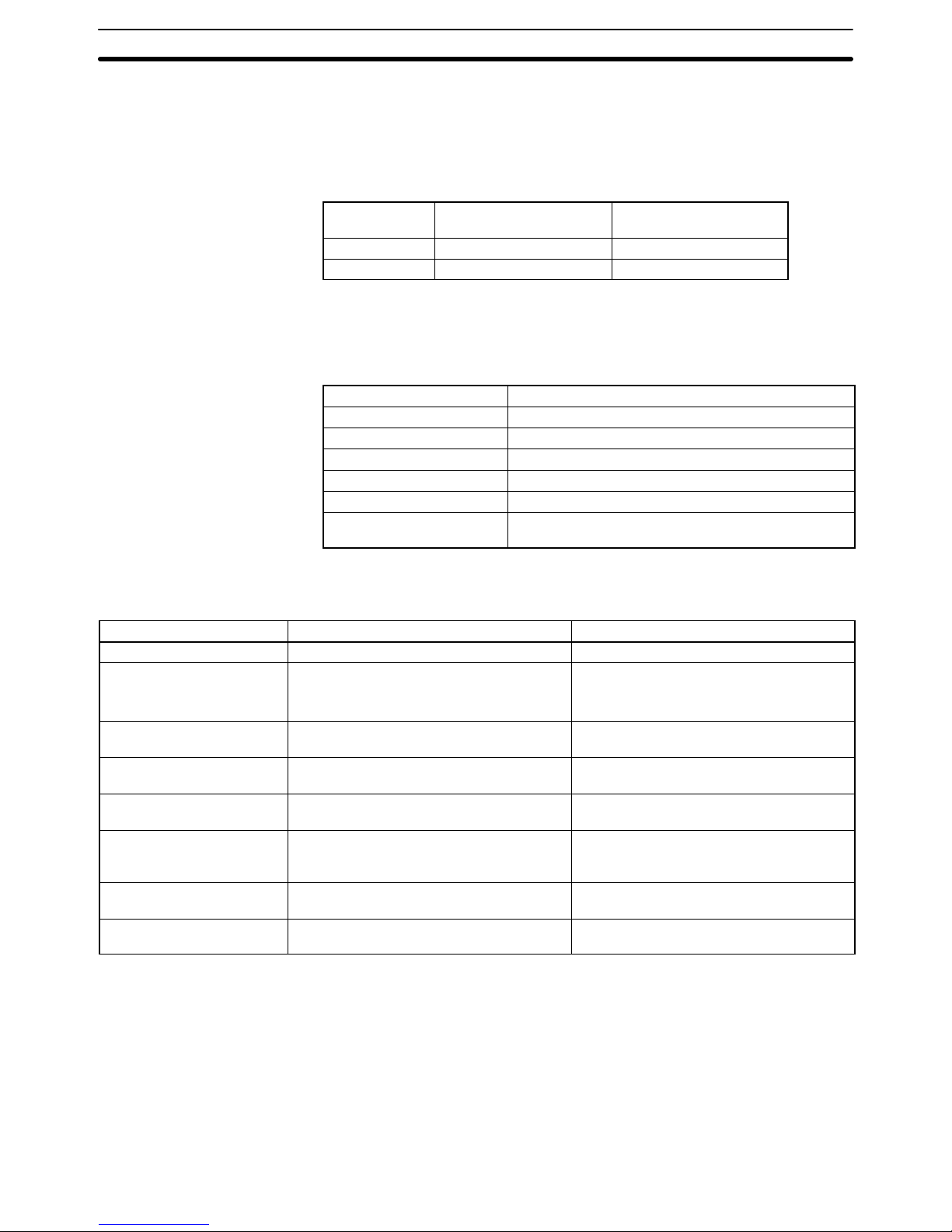
Connection Method The following diagram shows the connections between a host computer and a
3G2A9-AL001 Link Adapter. When RS-422 cable is used, up to 32 PCs can be
connected to one host computer.
3G2A9-AL001 Link Adapter
FG (connector hood)
Shield
CV-series PC
(2)SDB
(1)SDA
(8)RDB
(6)RDA
(4)RS
(5)CS
SDB
SDA
RDB
RDA
Recommended Cable The following cables are recommended for connecting the host computer and
Link Adapter. Other cables can be used if desired as long as they meet the required specifications.
Manufactured by Fujikura: UL2464 AWG28 x 5P IFS-RVV-SB (UL approved)
Manufactured by Hitachi: UL2464-SB 5P x AWG28 (UL approved)
Note 1. Ground the FG terminals of both the PC and the host computer to a a resis-
tance of 100 Ω or less. For details refer to the CV-series PC Installation
Guide and your host computer manual.
2. The following Connector and Connector Hood (both OMRON) are provided
with the CPU.
Connector XM2A-0901
Connector hood XM2S-0911
3. When using RS-422 cables to connect a Host Link System, the PC at each
end of the communications line must have the built-in termination resistance
connected by turning ON pin 6 of the DIP switch on the CPU. The other PCs
must have termination resistance disconnected by turning this pin OFF. If
termination resistance is not properly set, signal transmission will not be
possible (refer to 3-5 RS-422 Connections).
4. When connecting the shield to the frame ground, connect it at only one end
of each cable section to prevent current flow (refer to 3-1 Preparations).
RS-422 Connections Section 3-5
Page 38

33
Connect the f r ame ground to the shield at the connections to the PCs and at
either end of the connections between Link Adapters. An example is shown
below.
Host computer
3G2A9-AL004-(P)E
Link Adapter
RS-232C
(15 m max.)
3G2A9-AL001
Link Adapter
3G2A9-AL001
Link Adapter
Yes: Connect shield to FG.
No: Do not connect shield to FG.
CV-series PC CV-series PC CV-series PC
RS-422
Yes
No
No
Yes
Yes
Yes
No
No No
Yes
RS-422 RS-422
3-5-2 Host Link Unit Connections
The specifications for RS-422 connections to the Host Link Unit are described in
this subsection for port 2. When RS-422 cable is used, a host computer can be
connected to more than one PC.
Communications Port 1 Electrical characteristics: Conforming to EIA RS-232C
Direction of signal: Viewed from the Host Link Unit.
Maximum cable length: 500 m
Host Link Unit
connector pin no.
Signal Symbol Direction of signal
Input Output
Connector hood Frame ground FG --- --1 Send data A SDA (SD–) No Yes
2 Send data B SDB (SD+) No Yes
6 Receive data A RDA (RD–) Yes No
8 Receive data B RDB (RD+) Yes No
5
1
9
6
RS-422 Connections Section 3-5
Page 39

34
Line Connections The following diagram shows the connections between a Host Link Unit and a
3G2A9-AL004 Link Adapter. When RS-422 cable is used, multiple PCs can be
connected to one host computer by wiring through Link Adapters (see illustration on page 35).
3G2A9-AL004 Link Adapter
FG (connector hood)
Shield
Host Link Unit
(2)SDB
(1)SDA
(8)RDB
(6)RDA
(4)RS*
(5)CS*
SDB (5)
SDA (9)
RDB (1)
RDA (6)
*The RS and CS terminals
need not be connected as
long as the CTS selector is
turned ON
Note 1. Ground the FG terminals of both the PC and the host computer to a a resis-
tance of 100 Ω or less. For details refer to the CV-series PC Installation
Guide and your host computer manual.
2. The termination resistance must be turned ON at the Units (CPU, Host Link
Unit, Link Adapter) at each end of the communications line and must be
turned OFF at all other Units. Do not connect termination resistances to the
other Units or normal transmission operation will not be possible (refer to 3-8
1-to-N Connection Examples).
3. When connecting the shield to the frame ground, connect it at only one end
of each cable section to prevent current flow (refer to the next subsection
and to 3-9-4 Hood Assembly).
RS-422 Connections Section 3-5
Page 40

35
Connecting Shield to FG Connect the frame ground to the shield at the connections to the PCs and at ei-
ther end of the connections between Link Adapters. An example is shown below .
Host computer
3G2A9-AL004-(P)E
Link Adapter
RS-232C
(15 m max.)
3G2A9-AL001
Link Adapter
3G2A9-AL001
Link Adapter
Yes: Connect shield to FG.
No: Do not connect shield to FG.
CV-series PC CV-series PC CV-series PC
RS-422
Yes
No
No
Yes
Yes
Yes
No
No No
Yes
RS-422 RS-422
3-6 1-to-1 Connection Examples
3-6-1 Host Link Unit Connection to Host Computer
The diagrams below show 1-to-1 host link connections between the Host Link
Unit and a host computer via an RS-232C cable.
The wiring method varies with the communications port used and the communications method (full duplex or half duplex).
Communications via Communications Port 1
The following diagram shows 1-to-1 host link connections using communications port 1 i n f u l l duplex. Full-duplex communication must be set using the Host
Link Unit’s CPU Bus Unit System Setup.
Signal
name
SD (TXD)
RD (RXD)
RS (RTS)
CS (CTS)
SG (GND)
2
3
4
5
7
FG
RS-232C
interface
Pin
number
2
3
4
5
6
7
8
20
RS-232C
interface
1
Pin
number
Host Link Unit Host computer
Connector
hood
Shield
1
Connector
hood
Full Duplex
1-to-1 Connection Examples Section 3-6
Page 41

36
Half Duplex The following diagram shows 1-to-1 host link connections using communica-
tions port 1 in half duplex. Half-duplex communications must be set using the
Host Link Unit’s CPU Bus Unit System Setup.
Signal
name
SD (TXD)
RD (RXD)
RS (RTS)
CS (CTS)
SG (GND)
2
3
4
5
7
FG
CD (DCD) 8
RS-232C
interface
Pin
number
2
3
4
5
6
7
8
20
RS-232C
interface
1
Pin
number
Host Link Unit Host computer
Connector
hood
Shield
1
Connector
hood
Note The CTS selector of the Host Link Unit must be turned ON (fixed to 0 V).
Communications via Communications Port 2
The following diagram shows 1-to-1 host link connections using communications port 2 in full duplex. Full-duplex communications must be set using the
Host Link Unit’s CPU Bus Unit System Setup.
Signal
name
SD (TXD)
RD (RXD)
RS (RTS)
CS (CTS)
SG (GND)
2
3
4
5
9
FG
CD (DCD) 7
RS-232C
interface
Pin
number
2
3
4
5
6
7
8
20
RS-232C
interface
1
Pin
number
Host Link Unit Host computer
Connector
hood
Shield
Connector
hood
Full Duplex
1-to-1 Connection Examples Section 3-6
Page 42

37
Half Duplex The following diagram shows 1-to-1 host link connections using communica-
tions port 2 in half duplex. Half-duplex communications must be set using the
Host Link Unit’s CPU Bus Unit System Setup.
Signal
name
SD (TXD)
RD (RXD)
RS (RTS)
CS (CTS)
SG (GND)
2
3
4
5
9
FG
CD (DCD) 7
RS-232C
interface
Pin
number
2
3
4
5
6
7
8
20
RS-232C
interface
1
Pin
number
Host Link Unit Host computer
Connector
hood
Shield
Connector
hood
Note 1. Pins 1, 6, and 8 of the Host Link Unit must be connected when RS-422 is
used. These pins must not be connected when using RS-232C.
2. The CTS selector of the Host Link Unit must be turned ON (fixed to 0 V).
3-6-2 Host Link Unit Connection to PT
The diagrams below show 1-to-1 host link connections using OMRON’s NT20M
or NT600M PTs and the Host Link Unit via the PT’s NT600M-LK201 Host Link
Interface Unit. The connection method varies with the port.
The following diagram shows the connections via communications port 1.
Signal
name
RS-232C
interface
RS-232C
interface
Pin
number
Port 1 Host Link Interface Unit
Pin
number
SD (TXD)
RD (RXD)
RS (RTS)
CS (CTS)
SG (GND)
2
3
4
5
7
FG
3
4
5
6
7
8
20
2
Connector
hood
1
Shield
Connections via
Communications Port 1
1-to-1 Connection Examples Section 3-6
Page 43

38
The following diagram shows the connections via communications port 2.
Signal
name
SD (TXD)
RD (RXD)
RS (RTS)
CS (CTS)
SG (GND)
2
3
4
5
9
FG
RS-232C
interface
Pin
number
3
4
5
6
7
8
20
RS-232C
interface
2
Pin
number
Port 2 Host Link Interface Unit
Shield
Connector
hood
1
Note 1. Connect the shield to the connector hood and connector pin 1 of the Host
Link Unit. The other end of the shield must be left unconnected.
2. Turn ON the CTS selector of the Host Link Unit (fixed to 0 V) and specify
full-duplex communications with the CPU Bus Unit System Setup.
3. Refer to Appendix A Standard Models for a list of the PTs that can be used
with the NT600M-LK201 Host Link Interface Unit.
3-7 Optical Interface Connections
The distance between a CPU or Host Link Unit and the host computer connected
to it can be increased to a maximum of 500 m by using an optical interface.
3-7-1 Required Devices
The following devices are required to use an optical interface.
Name Model Required
number
Remarks
Optical Module Z3RN-A-5 2 RS-232C optical fiber conversion
Optical fiber
Z3F2-4DjM
(see note)
1 PCF
AC Adapter Z3-GP01 1 or 2 Two AC Adapters are required for
port 2 and one AC Adapter is
required for port 1.
Note Cables with lengths of 1, 5, 10, 15, 20, 25, 30, 40, 50, 60, 70, 80, 90, 100, 110,
120, 130, 140, 150, 160, 170, 180, 190, 200, 250, 300, 350, 400, 450, and 500 m
are available. When ordering, insert the required cable length before the M in the
model number (replacing the box: j).
Connections via
Communications Port 2
Optical Interface Connections Section 3-7
Page 44

39
3-7-2 Connections to Optical Module
The connection method of the optical interface varies with the communications
port.
It is possible to connect an Optical Module directly to communications port 1. By
turning on t h e 5 - V power supply switch of the Host Link Unit, 5 V is supplied to pin
14 of the communications port 1 so that no AC Adapter is required for the communications port 1.
Host Link Unit
communications
port 1
Conversion cable
Optical
module
Optical fiber
cable
Optical
module
Direct connection
Host
computer
AC Adapter
Power supply
It is impossible to connect an Optical Module to the 9-pin connector of the Host
Link Unit directly. You must prepare a conversion cable to connect the Optical
Module to the 9-pin connector. AC Adapters are required for the Optical Modules
at the Unit and at the host computer. The following diagram shows the connections of the Host Link Unit to the host computer via communications port 2.
Host Link Unit
communications
port 2
Conversion cable
Optical
module
Optical fiber
cable
Optical
module
Direct connection
Host
computer
AC Adapter
Power supply
Power supply
AC Adapter
The following diagram shows the connections of the 9-pin to 25-pin conversion
cable.
Signal
name
RS-232C
connector
Pin
number
Host Link Unit
Male connector (9 pins)
Optical Module
Female connector (25 pins)
Pin
number
SD (TXD)
RD (RXD)
RS (RTS)
CS (CTS)
SG (GND)
2
3
4
5
9
FG
3
4
5
6
7
8
20
2
Connector
hood
1
Shield
RS-232C
connector
See note
See note
Communications Port 1
(25-pin connector)
Communications Port 2
(9-pin connector)
Optical Interface Connections Section 3-7
Page 45

40
Note It is not necessary to connect these terminals before connecting the host com-
puter to the Host Link Unit as long as the CTS selector is turned ON.
3-8 1-to-N Connection Example
The following diagrams show connections between the Host Link Unit and Link
Adapters and between the Link Adapters and host computer.
FG
SD
RD
RS
CS
DR
SG
CD
ER
1
2
3
4
5
6
7
8
20
1
2
3
4
5
6
7
8
20
SDA
SDB
RDA
RDB
SG
FG
9
5
6
1
3
7
731659
9
5
6
1
3
7
9
5
6
1
3
7
1
2
6
8
4
5
0 V
0 V
0 V
0 V
Pin
no.
RS232C
interface
Pin
Host computer RS-232C
OR/selection
circuit
Pin
no.
Symbol
RS-422
Termination resistance
100
VAC
5 V
24 V
Fuse
FG
LG
3G2A9-AL004-(P)E Link Adapter
Transmission
Reception
Shield
External
connection
Shield
CTS
selection
Pin
no.
Pin no.Pin no.
RS-422
interface
To 100 Ω
max.
AC power supply
200
VAC
RS422
interface
SDA (SD –)
SDB (SD +)
RDA (RD –)
RDB (RD +)
FG
RS
CS
Connector
hood
Signal
Shield
Host Link Unit (or CPU)
Pin
3G2A9-AL001 Link Adapter
To 3G2A9-AL001
Link Adapter, CPU
or Host Link Unit
Symbol
*The RS and CS terminals
need not be connected on the
Host Link Unit as long as the
CTS selector is turned ON
Note 1. To connect more than one PC to a host computer , used the 3G2A9-AL004-E
or 3G2A9-AL004-PE Link Adapter (for RS-232C-to-RS-422 cable conversion) and the 3G2A9-AL001 Link Adapter (to branch to other Units).
2. The shield of the cable must be connected to the connector hood of the PC
for lines connecting PCs to Link Adapters, and to pin 7 on one and only one
Link Adapter on lines connecting two Link Adapters.
3. Leave Host Link Unit pins 3, 4, 5, 7, and 9 unconnected. (Leave CPU pins 3,
7, and 9 unconnected and short-circuit pins 4 and 5.)
1-to-N Connection Example Section 3-8
Page 46

41
Cable Lengths and Termination Resistance
When connecting more than one PC to a host computer using RS-422, but sure
to keep cable lengths within limits and to set termination resistance on the proper
Units as described below.
Kind of Cable Use shielded twisted-pair cable and separate the cables from other signal lines.
Cable Length The sum of all cable lengths must be 500 m or less and the branch line from each
Link Adapter must be 10 m or less.
Termination Resistance The CPUs, Host Link Units, or Link Adapters at each end of the trunk line must
have the termination resistance connected (turned ON). All other Units must
have the termination resistance disconnected (turned OFF). If termination resistance is not set correctly, signal transmission will not be possible.
The termination resistance is connected to the CPU by turning ON pin 6 on the
DIP switch on the CPU and disconnected by turning this pin OFF.
The termination resistance is connected to the Host Link Unit by turning ON the
termination resistance switch of the Host Link Unit and disconnected by turning
OFF the switch.
Host computer
RS-232C (15 m max.)
3G2A9-AL004-(P)E with
termination resistance ON
Trunk line
RS-422
3G2A9-AL001
Link Adapter
3G2A9-AL001
Link Adapter
Termination resistance OFF Termination resistance OFF Termination resistance ON
RS-422
Total cable length 500 m max.
10 m max. 10 m max.
RS-422
(branch)
RS-422
(branch)
1-to-N Connection Example Section 3-8
Page 47

42
3-9 Wiring
Use the following procedures to wire RS-232C and RS-422 cables.
Connect the shield to the frame ground (FG, the connector hood at the PC)
on the connector for the PC in all Systems and to one end of each line connecting two Link Adapters in RS-422 Systems. Refer to 3-5 RS-422 Connec-
tions for details on connections between Link Adapters.
3-9-1 Connecting the Shield to FG
1, 2, 3... 1. Cut the cable to the required length, leaving sufficient leeway for wiring
and laying the cables.
2. Use a razor blade to cut away the sheath, being careful not to damage
the braiding underneath. Cut away 25 mm for RS-422 cable; 40 mm for
RS-232C cable.
3. Use scissors to cut away all but 10 mm of the exposed braiding.
4. Use wire strippers to remove the insulation from the last 5 mm of each
wire.
5. Fold the braiding back over the end of the sheath.
6. Wrap aluminum foil tape over the top of the braiding for one and a half
turns.
Aluminum foil tape
3-9-2 Not Connecting the Shield to FG
1, 2, 3... 1. Cut the cable to the required length, leaving sufficient leeway for wiring
and laying the cables.
2. Use a razor blade to cut away the sheath. Cut away 25 mm for RS-422
cable; 40 mm for RS-232C cable.
3. Use scissors to cut away the exposed braiding.
4. Use wire strippers to remove the insulation from the last 5 mm of each
wire.
Wiring Section 3-9
Page 48

43
5. Wrap electrician’s tape over the top and end of the the cut sheath.
Electrician’s tape
3-9-3 Soldering
Use the following procedure when soldering connectors.
1, 2, 3... 1. Place heat-shrinking tubes over all wires. Be sure the tubes are far
enough away from the end so as not to interfere with the soldering.
2. Pre-solder all wires and connector terminals.
3. Solder the wires, inserting 4 mm of the exposed 5 mm of wire into the
connector terminal.
Soldering iron
Heat-shrinking tube
(inner dia. 1.5)
4. Move the heat-shrinking tubes onto the soldered area and shrink them
into place.
Heat-shrinking tube
Wiring Section 3-9
Page 49

44
3-9-4 Hood Assembly
Assemble the hood as shown in the following diagram.
Aluminum foil tape
Hood (FG) connected
to shield
Hood (FG) not connected to
shield
Boot
3-9-5 Recommended Cables and Connectors
Recommended Cable The following cables are recommended for connecting the host computer and
the Host Link Unit. Other cables can be used if desired as long as they meet the
required specifications.
Manufactured by Fujikura: UL2464 AWG28 x 5P IFS-RVV-SB (UL approved)
Manufactured by Hitachi: UL2464-SB 5P x AWG28 (UL approved)
Connector The following 9-pin connector, 25-pin connector, and connector hoods are pro-
vided with the Host Link Unit. The 9-pin connector is used at communications
ports 2 and 25-pin connector is used at communications port 1.
Item 9-pin connector 25-pin connector
Connector XM2A-0901 XM2A-2501
Connector hood XM2S-0911 XM2S-2511
3-9-6 Link Adapters
The following tables gives the specifications for Link Adapters suitable for use In Host Link Systems. Refer to
the C-series Link Adapters Installation Guide for details.
Link Adapter/
Application
Connection Supply voltage Operating
voltage range
Power
consumption
Weight
3G2A9-AL001
Branches RS-422
lines.
RS-422
RS-422RS-422
Not required –––
––– 250 g
max.
3G2A9-AL002-PE
Branches APF/PCF
lines.
Optical Fiber (APF/PCF)
Optical Fiber
(APF/PCF)
Optical Fiber
(APF/PCF)
100 to 120/
200 to 240 VAC
or 12 to 24 VAC/
DC
85 to 132/
170 to 246 VAC or
10.2 to 26.4 VAC/
DC
10 VA max. 900 g
max.
3G2A9-AL002-E
Branches PCF
lines.
Optical Fiber (PCF)
Optical Fiber
(PCF)
Optical Fiber
(PCF)
3G2A9-AL004-PE
Converters APF/
PCF, RS-422, and
RS-232C lines.
Optical Fiber
(APF/PCF)
RS-232C
RS-422
100 to 120/
200 to 240 VAC
85 to 110 VAC
170 to 220 VAC
10 VA max. 1 kg max.
3G2A9-AL004-E
Converters PCF,
RS-422, and
RS-232C lines.
Optical Fiber
(PCF)
RS-232C
RS-422
APF: all-plastic optical fiber cable; PCF: plastic-clad optical fiber cable
Wiring Section 3-9
Page 50

45
3-9-7 Cable Lengths
Wire Cables
RS-232C cable 15 m max.
Total length of RS-422 cable 500 m max.
Length of each RS-422 branch 10 m max.
Optical Fiber Cables
Cable Units with “P” in suffix Units without “P” in suffix
APF 20 m Connection impossible
PCF 200 m 800 m
Note If the distance between a Link Adapter and a CPU’s host interface, a Link Adapt-
er and Host Link Unit, or a Link Adapter and another Link Adapter must be more
than 800 m, use 3G2A9-AL005(-P) or 3G2A9-AL006(-P) Link Adapters with
quartz fiber cable. Refer to the C-series Link Adapters Installation Guide for details.
Wiring Section 3-9
Page 51

47
SECTION 4
Communications
This section describes both the test methods used to check communications and the specifications of the commands that are
used for communications control and timing. For communications in CV (FINS) mode, refer to FINS Command Reference
Manual.
4-1 Initial Communications Test 48. . . . . . . . . . . . . . . . . . . . . . . . . . . . . . . . . . . . . . . . . . . . . . . .
4-2 Wrap Communications Test 49. . . . . . . . . . . . . . . . . . . . . . . . . . . . . . . . . . . . . . . . . . . . . . . . .
4-2-1 Connector Wiring 50. . . . . . . . . . . . . . . . . . . . . . . . . . . . . . . . . . . . . . . . . . . . . . . . . .
4-2-2 Test Contents 51. . . . . . . . . . . . . . . . . . . . . . . . . . . . . . . . . . . . . . . . . . . . . . . . . . . . .
4-2-3 Test Errors and Possible Corrections 52. . . . . . . . . . . . . . . . . . . . . . . . . . . . . . . . . . .
4-3 C-mode Commands 52. . . . . . . . . . . . . . . . . . . . . . . . . . . . . . . . . . . . . . . . . . . . . . . . . . . . . . .
4-3-1 Communications Protocol 53. . . . . . . . . . . . . . . . . . . . . . . . . . . . . . . . . . . . . . . . . . .
4-3-2 Blocks 53. . . . . . . . . . . . . . . . . . . . . . . . . . . . . . . . . . . . . . . . . . . . . . . . . . . . . . . . . .
4-3-3 Blocks over 131 Characters Long 54. . . . . . . . . . . . . . . . . . . . . . . . . . . . . . . . . . . . .
4-3-4 Right to Send 55. . . . . . . . . . . . . . . . . . . . . . . . . . . . . . . . . . . . . . . . . . . . . . . . . . . . .
4-3-5 Frame Checksum (FCS) Calculation 56. . . . . . . . . . . . . . . . . . . . . . . . . . . . . . . . . . .
4-4 Sending Commands to Host Computers 57. . . . . . . . . . . . . . . . . . . . . . . . . . . . . . . . . . . . . . .
4-4-1 Transfer of Right to Send 57. . . . . . . . . . . . . . . . . . . . . . . . . . . . . . . . . . . . . . . . . . . .
4-4-2 Commands from PC Instructions 57. . . . . . . . . . . . . . . . . . . . . . . . . . . . . . . . . . . . . .
4-4-3 Command Format Received by Host Computers 58. . . . . . . . . . . . . . . . . . . . . . . . .
4-4-4 Response Format Sent by Host Computer 59. . . . . . . . . . . . . . . . . . . . . . . . . . . . . . .
4-4-5 Commands from PCs 59. . . . . . . . . . . . . . . . . . . . . . . . . . . . . . . . . . . . . . . . . . . . . . .
4-5 Communications Timing 64. . . . . . . . . . . . . . . . . . . . . . . . . . . . . . . . . . . . . . . . . . . . . . . . . . .
Page 52

48
4-1 Initial Communications Test
Prior to actual communications between the PC(s) and host computer, check
the system by following the steps listed below.
1, 2, 3... 1. Check the settings of the DIP switches and selectors.
2. Make sure the baud rate, interface, and data formats match between the
Unit(s) and the host computer.
3. Check the connections between the Unit(s) and the host computer.
4. Turn on power to the Unit(s), host computer, and any Link Adapters or Optical Interfaces in the System. If an error occurs, check all connections and
settings again and correct the error before continuing.
5. If the Units are ready, prepare and execute a test from the host computer.
There are two test methods that can be used:
• Test program: Write a simple test program at the host computer. A sam-
ple program is provided in the next subsection.
• Terminal mode: Input commands directly from the host computer in the
terminal mode and check the response.
If the test is completed successfully, the system is operational.
Note 1. Input commands carefully at the host computer when usin g Terminal Mode.
2. If a normal response (00 or 00 00) is not returned, refer to remainder of this
section for communications procedures and to Section 5 C-mode Com-
mands and Section 6 CV-mode Commands for details on commands and
responses.
3. If any of the following occur during the test, correct the error referring to Sec-
tion 6 Maintenance and Troubleshooting. Indicators are those on the Host
Link Unit.
The RUN indicator goes out
The RD1 or RD2 indicator does not light
The SD1 or SD2 indicator does not light
The ERH, ERC1, or ERC2 indicator lights
An error response is received
No response is received
Communications Test Program
The following program example is designed to send test data to the PC and return it unaltered to the host computer. By executing this program, the transmit
data and receive data are both displayed on the screen of the host computer. If
the transmit data and the receive data match, the system is operating properly. If
an error has occurred while executing the program, the error number and the
line in which the error has occurred will be displayed.
Note The FCS calculation subroutine starting from statement 180 is for data transmis-
sion. The data length L will differ for the response because the response contains other data such as FCS and *.
Host Computer and PC Host computer: IBM PC/AT compatible
PC unit number (used as node number in Host Link System): 00
Initial Communications Test Section 4-1
Page 53

49
Program
10 CLOSE 1
20 CLS
30 ON ERROR GOTO 300
40 OPEN ”COM:E72” FOR OUTPUT AS #1 Open RS-232C. . . .
50 ’∗∗∗∗∗∗∗∗∗∗∗∗∗∗∗∗∗∗∗∗∗∗∗∗∗∗∗∗∗∗∗∗∗∗∗∗∗∗∗∗∗∗∗∗∗∗∗∗∗∗∗∗∗∗∗∗∗∗∗∗∗∗∗
60 ∗KEYIN
70 INPUT ”TEST DATA INPUT -----”, TD$ Test data input
80 TC$=”@00TS” Creation of Unit no. and header code. . . . . . . . . . . . . . . . . . . . . . . . . . . .
90 T$=TC$+TD$ Creation of test command. . . . . . . . . . . . . . . . . . . . . . . . . . . . .
100 GOSUB 190 Calculation of Frame Checksum. . . . . . . . . . . . . . . . . . . . . . . . . . . . .
110 TXD$=T$+FCS$+”∗” Receive data. . . . . . . . . . . . . . . . . . . . .
120 PRINT TXD$ Receive data. . . . . . . . . . . . . . . . . . . . . . . . . . . .
130 PRINT #1, TXD$ Transmission. . . . . . . . . . . . . . . . . . . . . . .
140 INPUT #1, RXD$ Reception. . . . . . . . . . . . . . . . . . . . . . .
150 PRINT RXD$ Receive data display. . . . . . . . . . . . . . . . . . . . . . . . . . . .
160 GOTO 70
170 ’∗∗∗∗∗∗∗∗∗∗∗∗∗∗∗∗∗∗∗∗∗∗∗∗∗∗∗∗∗∗∗∗∗∗∗∗∗∗∗∗∗∗∗∗∗∗∗∗∗∗∗∗∗∗∗∗∗∗∗∗∗∗∗
180 ∗FCSSET
190 L=LEN(T$) Number of transmit data before FCS. . . . . . . . . . . . . . . . . . . . . . . . . . . . .
200 A=0 Setting of initial value for EOR calculation. . . . . . . . . . . . . . . . . . . . . . . . . . . . . . . . . . . . .
210 FOR J=1 TO L
220 TJ$=MID$(T$, J, 1)
230 A=ASC(TJ$) XOR A
240 NEXT J
250 FCS$=HEX$(A)
260 IF LEN(FCS$)=1 THEN FCS$=”0”+FCS$
270 RETURN
280 ’∗∗∗∗∗∗∗∗∗∗∗∗∗∗∗∗∗∗∗∗∗∗∗∗∗∗∗∗∗∗∗∗∗∗∗∗∗∗∗∗∗∗∗∗∗∗∗∗∗∗∗∗∗∗∗∗∗∗∗∗∗∗∗
290 ∗EROPE
300 PRINT ”ERL=”;ERL, ”ERR=”;ERR Display of line no. containing error and error no.. . . . . .
310 CLOSE 1
320 END Closes RS-232C. . . . . . . . . . . . . . . . . . . . . . . . . . . . . . . . . . . . .
330 ’∗∗∗∗∗∗∗∗∗∗∗∗∗∗∗∗∗∗∗∗∗∗∗∗∗∗∗∗∗∗∗∗∗∗∗∗∗∗∗∗∗∗∗∗∗∗∗∗∗∗∗∗∗∗∗∗∗∗∗∗∗∗∗
4-2 Wrap Communications Test
This section explains the wrap communications test for the two communications
ports of the Host Link Unit.
Execute the wrap communications test as follows:
1, 2, 3... 1. Set the unit number to an appropriate number within a range of 0 to 15.
2. Set the node number to an appropriate number within a range of 0 to 31.
3. Set the DIP switch as shown in the following tables:
Wrap Communications Test at Communications Port 1
Pin Setting
2 OFF
5 ON
6 OFF
Wrap Communications Test Section 4-2
Page 54

50
Wrap Communications Test at Communications Port 2
Pin Setting
3 (see note) OFF
5 ON
6 ON
Note Pin 3 need not be set if the test is executed using RS-422.
4. Specify either RS-232C or RS-422 when executing the test at communications port 2.
5. Wire the connectors as described under Connector Wiring following this
procedure.
6. Turn on the PC. The wrap communications test will be executed automatically. The status of each indicator will be as follows:
Test port Status Indicator
TS1 TS2
Communications
Executing Lit Not lit
port 1
Completed Flashes Not lit
Communications
Executing Not lit Lit
port 2
Completed Not lit Flashes
Note If there is no I/O table when the PC is turned on, no test will be executed and the
indicators will display the status shown in the following table. If this occurs, generate an I/O table and then execute the test.
Test port Indicator
TS1 TS2 ERH
Communications
port 1
Flashes Not lit Lit
Communications
port 2
Not lit Flashes Lit
7. T o execute the test for a different port, repeat from step 3 and turn o n th e PC
again or restart the Unit.
4-2-1 Connector Wiring
Wire the connectors for the wrap communications test according to the communications port as follows:
Communications Port 1
Signal
SD
RD
RS
CS
CD
2
3
4
5
8
Pin no.
Wrap Communications Test Section 4-2
Page 55

51
Communications Port 2
Signal
SD
RD
RS
CS
CD
2
3
4
5
7
Pin no.
Using RS-232C
Signal
SDA
SDB
RDA
RDB
1
2
6
8
Pin no.
Using RS-422
4-2-2 Test Contents
The wrap communications test is executed at the communications port designated on the DIP switch. By wiring the connector as shown in the previous diagrams, data is looped back. The data looped back is compared with the original
data to ascertain if they match.
Specifications Baud rate: 1,200, 2,400, 4,800, 9,600, and 19,200 bps
(switched in sequence automatically 5 times)
Stop bits: 2
Parity: Even
Data length: 7 bits
Data Transferred The C-mode command TS is used to transfer 200 characters (209 characters
including the header, all in hexadecimal, 00 to 63).
Completion of Test When the test finishes, the TS1 or TS2 indicator, which has been lit, will start
flashing. If there is an error during the test, the ERC1 indicator, ERC2 indicator,
or ERH indicator will light
Indicators The following table shows the meaning of each indicator.
Indicator Status Meaning
TS1 Lit The test is being executed at port 1.
Flashes The test at port 1 has been completed.
TS2 Lit The test is being executed at port 2.
Flashes The test at port 2 has been completed.
ERC1 Lit Port 1 has a transmission error.
ERC2 Lit Port 2 has a transmission error.
ERH Lit There is a unit number setting or PC error, or no I/O
table has been made.
Test Results The results of the test that has been executed will be recorded in word 15 in the
portion of the CPU Bus Unit Area allocated to the Host Link Unit in the PC. W ords
in this area are allocated according to unit number.
15 14 13 12 11 10 9 8 76543210
00000000000000
RS-232C/RS-422 status (0: RS-232C; 1: RS-422)
Test port
Word: 1500 + (25 x Unit no.) + 15
Bit
+15
Wrap Communications Test Section 4-2
Page 56

52
The result of the test for each communications speed is recorded at words 16 to
20 in the portion of the CPU Bus Unit Area allocated to the Host Link Unit in the
PC. The following is an example of the contents of the record at a baud rate of
1,200 bps.
15 14 13 12 11 10 9 8 76543210
00000000
1: Comparison error
1: FCS error
1: Framing error
1: Overrun error
1: Parity error
1: Timeout error
1: CD check error
Word: 1500 + (25 x Unit no.) + 16
Bit
+16
0: Normal response 1: Error
The contents of the following records are
the same as the above.
+17: The result at 2,400 bps
+18: The result at 4,800 bps
+19: The result at 9,600 bps
+20: The result at 19,200 bps
4-2-3 Test Errors and Possible Corrections
When there is an error during the wrap communications test, the cause of the
error can be determined from the Host Link Unit’s indicators. The following table
lists the errors and probable causes of errors that can occur during the wrap
communications test.
Indicator Probable cause Possible correction
RUN indicator is not lit. No power is supplied to the PC or the
voltage of the power supplied to the
PC is low.
Supply power to the PC or increase
the voltage of the power supplied to
the PC.
An error occurred in the Host Link
Unit.
Restart the PC. If an error occurs
again, replace the Host Link Unit.
The Host Link Unit is not properly
secured with screws.
Tighten the screws.
The mounting position of the Host Link
Unit is wrong.
Mount the Host Link Unit to the correct
slot.
TS1 or TS2 indicator flashes and ERH
indicator is lit.
The unit number setting is wrong (the
same number has been assigned to
two or more Units or the number is not
between 0 and 16).
Set the unit number correctly and
restart the PC.
The I/O table is not set correctly. Set the I/O table correctly.
TS1 or TS2 indicator flashes and EC1
or ERC2 indicator is lit.
DIP switch pin 2 or 3 is ON during the
wrap communications test in
RS-232C.
Set DIP switch pin 2 or 3 to OFF and
restart.
The wiring of the connector is wrong. Wire the connector correctly.
Others Check the contents of the CPU Bus
Unit Area.
4-3 C-mode Commands
This section describes the communications method used in C mode. The commands used in C mode and the basic communications method are the same as
those used with the C-series PCs and are the same as the C-mode commands
used with the CPU’s host interface. Details on commands not supported by the
host interface are provided in Section 5 C-mode Commands. Refer to the CV-
series Operation Manual: Host Interface for all other C-mode commands. The
commands and command formats are the same for all other C-mode commands
regardless of whether the host interface or the Host Link Unit is used.
C-mode Commands Section 4-3
Page 57

!
53
Caution The node number assigned to a Host Link Unit on a Host Link System network is
called the “ u n i t number” for the PC in the PC Setup and in the header portions of
command formats in the CV-series PC Operation Manual: Host Interface. When
coding commands for the Host Link Unit, be sure to use the node number and
not the unit number.
All commands and responses are transmitting in ASCII. Be sure that the data is
in the correct form (BCD or hexadecimal) before converting it to ASCII for transmission. Data is handled in hexadecimal unless otherwise specified.
4-3-1 Communications Protocol
The host computer has the initial right to send. Data transfer between the host
computer and the Host Link System is therefore initiated when the computer
sends a command to a PC in the Host Link System. The arrows in the following
diagram illustrate transfer of the right to send. Each command and each response is sent as a block, with longer block divided into two or more frames, as
described in more detail later. Responses cannot be split into multiple frames.
FCS
FCS
FCS
FCS
Node No.
Command block
Header
Text
Terminator
Node No.
Header
Text
Terminator
PC
Node No.
Header
Text
Delimiter
First frame
Delimiter
Next frame transmission
enabled
Text
Terminator
End frame
Node No.
Response block
Header
Text
Terminator
Host computer
Response block
Command block
FCS
4-3-2 Blocks
Data is sent in a Unit called a block. The data block sent from the host computer
to the Host Link System is called a command block. The block returned from the
PC to the computer is called a response block. The terminator in the command
block enables the PC to send a response. The terminator in the response block
enables the host computer to send another command.
Block Format
@
xx
xx xx
Node
No.
Header Text FCS Terminator
s
x 10
0
x 10
1
FCS calculation range (refer to page 56)
*
C-mode Commands Section 4-3
Page 58

54
Node Number The block format includes a node number so that the host computer can identify
the Unit that the host computer is communicating with. If the Unit is a CPU, the
node number set in the PC Setup must be used (the node number is called the
unit number in the PC Setup). If the Unit is a Host Link Unit using port 1, 00 (30,
30) must be used. If the Unit is a Host Link Unit using port 2, the value set on the
node number setting switch on the front panel of the Host Link Unit must be designated.
4-3-3 Blocks over 131 Characters Long
Each block is usually made up of one Unit called a frame, but long blocks of data
(over 131 characters) must be divided into more than one frame. The first frame
can have up to 131 characters, and subsequent frames can have up to 128 characters. In this case, the beginning and intermediate blocks end with a delimiter
(CR), instead of a terminator (*CR).
@
xx
xx xx
xx
xx
Node
No.
Header Text no. 1 (123 characters max.) FCS
Text no. 2 (125 characters max.) FCS Delimiter
Text no. 3 (124 characters max.) FCS Terminator
s
x 10
0
x 10
1
FCS calculation range (refer to page 56)
First Frame (131 Characters or Less)
s
FCS calculation range (refer to page 56)
Intermediate Frame(s) (128 Characters or Less)
s
FCS calculation range (refer to page 56)
Last Frame (128 Characters or Less)
*
Delimiter
Note Do not separate a single word of data into different frames for any write com-
mand (such as WR, WL, WH, WC, or WD).
C-mode Commands Section 4-3
Page 59

55
4-3-4 Right to Send
The terminator in a command block transferred by the host computer enables
the PC to send a response.
FCS
FCS
Node No.
Command block
Header
Text
Terminator
Node No.
Header
Text
Terminator
Right to send transferred
Response block
Host Computer
PC
To send a command block with more than one frame from the computer, initially
send only the first frame in the block and wait for the PC to return a delimiter. Do
not send the next frame until the host computer has received the delimiter.
FCS
FCS
FCS
FCS
Delimiter
Next frame trans-
mission enabled
Node No.
Header
Text
Delimiter
First frame
Text
Delimiter
Delimiter
Next frame transmission enabled
Text
Terminator
End frame
Node No.
Header
Text
Terminator
Response block
Command block
Host computer
PC
Intermediate frame
C-mode Commands Section 4-3
Page 60

56
4-3-5 Frame Checksum (FCS) Calculation
The frame checksum is an 8-bit value converted into two ASCII characters. The
8-bit value is the result of an EXCLUSIVE OR sequentially performed between
each character in a transmission, from the first character in the frame to the last
character of the text in that frame.
@ 10 RR 0000001 42 * CR
@ 0100 0000
XOR
1 0011 0001
XOR
0 0011 0000
XOR
R 0101 0010
1 0011 0001
Result 0100 0010
↓↓
42
Example
Converted to hexadecimal
and treated as ASCII
Node
No.
Header Text FCS Termi-
nator
FCS Calculation Program The following program is an example of how frame checksum calculations can
be performed on received data.
400 ∗FCSCHECK
405 L=LEN(RESPONSE$) Transmit/receive data. . . . . . . . . . . . . . . . . . . . .
410 Q=0:FCSCK$=” ”
415 A$=RIGHTS$(RESPONSE$, 1)
417 PRINT RESPONSE$, A$, L
420 IF A$=”∗” THEN LENGS=LEN(RESPONSE$)–3 ELSE LENGS=LEN(RESPONSE$)–2
430 FCSP$=MID$(RESPONSE$, LENGS+1, 2) Receive FCS data
440 FOR I=1 TO LENGS Number of characters in FCS calculation range.. . . . . . . . . . . . . . . . . . . . .
450 Q=ASC(MID$(RESPONSE$, I, 1)) XOR Q
460 NEXT I
470 FCSD$=HEX$(Q) FCS calculation result. . . . . . . . . . . . . . . . . . . . . . . . .
480 IF LEN(FCSD$)=1 THEN FCSD$=”0”+FCSD$
490 IF FCSD$<>FCSP$ THEN FCSCK$=”ERR”
495 PRINT ”FCSD$=”;FCSD$, ”FCSP$=”;FCSP$, ”FCSCK$=”;FCSCK$
500 RETURN
Note 1. Received data contains an FCS, delimiter/terminator, etc. If the data is not
received normally, however, any of these parts may be missing or corrupted.
Be sure to allow for the possibility of missing or corrupted data when receiving data at the host.
2. In this example, the code for CR (CHR$ (13)) is not included in RESPONSE$. Modify lines 415 and 420 to include the code for CR.
C-mode Commands Section 4-3
Page 61

57
4-4 Sending Commands to Host Computers
Unlike the host interface on the CPU, a Host Link Unit has the right to start communications. This means that the PC can send commands (i.e., SEND(192),
RECV(193), and CMND(194) instructions) to the host computer. Using this function, the PC can inform of the host computer of any error in operation. Therefore
the host computer does not need to communicate with the PC regularly, which
can reduce host computer overhead. Furthermore, a PC equipped with a SYSMAC NET Link Unit or SYSMAC LINK Unit can send commands to host computers connected to PCs on remote networks.
Note As a rule, communications initiated by Host Link Units should be used only when
a PC is connected 1-to-1 to a host computer. If a host computer is connected to
multiple PCs, simultaneous or overlapping transmissions from different PCs will
collide, preventing proper communications. If you need to used Host Link Unitinitiated communications is a 1-to-N Host Link System, you will need to program
the PCs so that no two or more transmissions will interfere with each other.
4-4-1 Transfer of Right to Send
A Host Link Unit that has received a SEND(192), RECV(193), or CMND(194)
instruction from the PC has the right to send the command to the host computer .
After the Host Link Unit has sent the command and the host computer detects
the terminator of the command, the right to send will be transferred to the host
computer, and the host computer will return a response.
FCS
FCS
Node No.
Command block
Header
Text
Terminator
Node No.
Header
Text
Terminator
Right to send transferred
Response block
Host Link Unit
Host Computer
4-4-2 Commands from PC Instructions
The PC sends commands (SEND(192), RECV(193), and CMND(194) instructions) in the direction opposite to the normal direction of communications in the
Host Link System. Therefore, be aware of the following.
1, 2, 3... 1. SEND(192), RECV(193), and CMND(194) instructions sent by the PC are
converted into the CV-mode command format for network communications.
2. It is necessary to prepare a program to process the commands that the host
computer receives. Interrupt processing is used for the reception of a command, so the program must be prepared with care (refer to 3-6 Communica-
tions Timing).
Sending Commands to Host Computers Section 4-4
Page 62

58
3. The control data set is different from usual control data when commands
(SEND(192), RECV(193), CMND(194) instructions) are sent by the PC.
For program examples that include commands for the host computer, refer to
Appendix D Sample Programs Including Commands for Host Computer.
4-4-3 Command Format Received by Host Computers
CV-mode commands addressed to a host computer are received in the following
format by the host computer.
@xxOF08x0x0xxxxx
xxxxxxxxxxxxxx
xx
ICF RSV GCNT DNA DA1
SNA SA1 SA2 SID
FCS
DA2
Node
No.
Header code
Response delay
Command code
Data (1,080 characters max.)
Terminator
*
s
Node Number The block format includes a node number so that the host computer can identify
the Unit that the host computer is communicating with. If the Host Link Unit uses
port 1, 0 0 (30, 30) must be used. If the Host Link Unit uses port 2, the value set on
the node number setting switches on the front panel of the Host Link Unit must
be designated.
Header Code The header code of the command block format must be set to OF (4F, 46).
Response Delay The response delay must be set to 0 (39) for any FINS command.
ICF Set to 80 (38, 30) if a response from the host computer is required and set to 81
(38, 31) if no response is required.
RSV The port number to which the host computer is connected is set.
Examples:
Communications port 1: 00 (39, 30) or 01 (39, 31)
Communications port 2: 02 (30, 32)
GCNT Subtract the number of relaying networks (SYSMAC LINK or SYSMAC NET)
from 2 and set the resulting value.
Examples:
The number of networks is 0: 02 (30, 32)
The number of networks is 1: 01 (30, 31)
The number of networks is 2: 00 (30, 30)
DNA, DA1, DA2 DNA, DA1, and DA2 specify the Host Link Unit through which the data is sent.
DNA: Set to 00 through 7F to specify the network address of the PC to which the
Host Link Unit is mounted.
DA1: Set to 01 through 7E to specify the node number (unit number) of the PC.
DA2: Set to 10 through 1F to specify the unit address of the Host Link Unit.
SNA, SA1, SA2 SNA, SA1, and SA2 specify the network addresses of the source node.
SNA: Set to 00 through 7F to specify the network address of the source node.
SA1: Set to 01 through 7E to specify the node number of the source node.
SA2: Set to the unit address of the source node.
Sending Commands to Host Computers Section 4-4
Page 63

59
SID Automatically set by the CPU for SEND(192), RECV(193), and CMND(194)
instructions.
4-4-4 Response Format Sent by Host Computer
When a CV-mode command is received by the host computer, the host computer must return a response in the following format.
@xxOF0 C00002xxxx
xxxxxxxxxxxxxx
ICF RSV GCNT DNA DA1
SNA SA1 SA2 SIDDA2
0
Node no.
Header
Command code
xxxx xx
Response code Data (1,076 characters)
FCS
Terminator
*
s
ICF Set to C0 (43, 30).
RSV Set to 00 (30, 30).
GCNT Set to 02 (39, 32)
DNA, DA1, DA2 Return the contents of SNA, SA1, and SA2 set in the command block format.
SNA, SA1, SA2 Return the contents of DNA, DA1, and DA2 set in the command block format.
SID Return the contents set in the command block format.
Command Code Return the contents set in the command block format.
Text The response block format can consist of 1,115 characters maximum; the num-
ber of characters used for data excluding the response code must be within
1,076.
4-4-5 Commands from PCs
The SEND(192), RECV(193), and CMND(194) instructions are used in the PC’s
user program to execute data communications or controlling the host computer
via Host Link System commands. This can be done either to a host computer
connected to the local PC or to a host computer connected to a PC linked to the
local PC via one or more networks. To send commands using SEND(192),
RECV(193), and CMND(194) instructions to the host computer , the control data
must be set as explained below. Refer to the CV-series PC Operation Manual:
Ladder Diagrams for details.
Sending Commands to Host Computers Section 4-4
Page 64

60
SEND(192) Instruction The SEND(192) instruction enables the memory area data in the local PC to be
sent to the host computer.
When the SEND(192) instruction is executed, the CV-mode command
“MEMORY AREA WRITE” (command code 0102) is sent to the host computer in
the following command block format.
@xxOF08x0x0xxxxx
xxxxxxxxxx0102
xx
ICF RSV GCNT DNA DA1
SNA SA1 SA2 SID
FCS
DA2
Node
No.
Header code
Response delay
Command code
Terminator
Data
(1,080 characters max.)
*
r
Before executing the SEND(192) instruction, it is necessary to set the following
control data beginning with the first control data word.
(*1) Response designation (0: Response required; 1: Response not required)
15141312111098 3210Bit
C + 0
Word
C + 1
C + 2
C + 3
C + 4
*10000 0000
7654
Response monitor time (Unit: 0.1 s)
Destination node number Destination unit address
Destination network address
Communications port no.
No. of words to be transferred
Host Link Unit Communications port no.
No of retries
1, 2, 3... 1. No. of words to be transferred: Set the total number of words of data to be
transmitted to the host computer.
2. Host Link Unit communications port no.: Set the communications port number of the Host Link Unit that is connected to the host computer.
3. Destination network address: Set the network address of the destination
node. Set to 00 for communications within the local network.
4. Destination node number: Set the destination node number. Set to 00 for
transmissions within the local PC.
5. Destination unit address: Set the unit address of the Host Link Unit that is
connected to the host computer.
6. Response designation: Usually set this bit to 0 (OFF). If no response is required, set this bit to 1 (ON).
7. Communications port no.: Set the port number of the PC sending the
SEND(192) instruction.
8. No. of retries: Set the upper limit of the number of retries for obtaining a response after the SEND(192) instruction is sent.
Sending Commands to Host Computers Section 4-4
Page 65

61
9. Response monitor time: Set the response monitor time if the response designation is set to OFF.
The setting range of each control data item is as follows:
Item Range
No. of words transferred 0001 to 0100 (1 to 256 words)
Host Link Unit
communications port no.
00 or 01: Communications port 1
02: Communications port 2
Destination network
address
00: Local network
01 to 7F: Network address (1 to 127)
Destination node number 00: Within local PC
01 to 7E: Node number (1 to 126) (SYSMAC NET)
01 to 3E: Node number (1 to 62) (SYSMAC LINK)
Destination unit address 10 to 1F: Host Link Unit (unit numbers 1 to 15)
Response response 0 (OFF): Response required
1 (ON): No response required
Communications port no. 0 to 7 (0 to 7)
No. of retries 0 to F (0 to 15)
Response monitor time 0000: Default (2 s)
0001 to FFFF (0.1 to 6,553.5 s with 0.1-s increments)
Note In order to execute the SEND(192) instruction properly, it is necessary to pre-
pare a program on the host computer so that the host computer will process the
data that the host computer has received.
RECV(193) Instruction The RECV(193) instruction enables data from the host computer to be written to
the memory areas of the local PC.
When the RECV(193) instruction is executed, the CV-mode command
“MEMORY AREA READ” (command code 0101) will be sent to the host computer in the following command block format.
@xxOF08x0x0xxxxx
xxxxxxxxxx0101
xx
Node No.
Response delay
Header code ICF RSV GCNT DNA DA1
SNA SA1 SA2 SID Command code
FCS Terminator
DA2
Data
(1,080 characters max.)
*
r
Sending Commands to Host Computers Section 4-4
Page 66

62
Before executing the RECV(193) instruction, it is necessary to set the following
control data beginning with the first control data word.
15 14 13 12 11 10 9 8 3 2 1 0 Bit
C + 0
Word
C + 1
C + 2
C + 3
C + 4
*10000 0000
7654
Response monitor time (Unit: 0.1 s)
Host Link Unit Communications port no.
Source node number Source unit address
Source network address
Communications port no.
No. of retries
No. of words to be transferred
1, 2, 3... 1. No. of words to be transferred: Set the total number of words of data to be
transmitted from the host computer.
2. Host Link Unit communications port no.: Set the communications port number of the Host Link Unit that is connected to the host computer.
3. Source network address: Set the network address of the source node. Set to
00 for communications within the local network.
4. Source node number: Set the source node number. Set to 00 for transmissions within the local PC.
5. Source unit address: Set the source unit address of the Host Link Unit that is
connected to the host computer.
6. Communications port no.: Set the port number of the PC sending the
RECV(193) instruction.
7. No. of retries: Set the upper limit of the number of retries for obtaining a response after the RECV(193) instruction is sent.
8. Response monitor time: Set the response monitor time, during which the
Host Link Unit waits for the response.
The setting range of each control data item is as follows:
Item Range
No. of words 0001 to 0100 (1 to 256 words)
Host Link Unit
communications port no.
00 or 01: Communications port 1
02: Communications port 2
Source network address 00: Local network
01 to 7F: Network address (1 to 127)
Source node number 00: Within local PC
01 to 7E: Node number (1 to 126) (SYSMAC NET)
01 to 3E: Node number (1 to 62) (SYSMAC LINK)
Source unit address 10 to 1F: Host Link Unit (unit numbers 1 to 15)
Communications port no. 0 to 7 (0 to 7)
No. of retries 0 to F (0 to 15)
Response monitor time 0000: Default (2 s)
0001 to FFFF (0.1 to 6,553.5 s with 0.1-s increments)
Note In order to execute the RECV(193) instruction properly, it is necessary to pre-
pare a program on the host computer so that the host computer will process the
instruction that the host computer has received and transmit the proper data.
Sending Commands to Host Computers Section 4-4
Page 67

63
CMND(194) Instruction The CMND(194) instruction enables the Host Link Unit to control the host com-
puter using CV-mode commands and responses.
When the CMND(194) instruction is executed, the CV-mode command set with
the control data will be sent to the host computer in the following command block
format.
@xxOF08x0x0xxxxx
xxxxxxxxxxxxxx
xx
Node No.
Response delay
Header code ICF RSV GCNT DNA DA1
SNA SA1 SA2 SID Command code
FCS Terminator
DA2 Data
(1,080 characters max.)
*
r
Before executing the CMND(194) instruction, it is necessary to set the following
control data beginning with the first control data word.
(*1) Response designation (0: Response required; 1: Response not required)
15 14 13 12 11 10 9 8 3 2 1 0 Bit
C + 0
Word
C + 2
C + 3
C + 4
C + 5
*10000 0000
7654
Response monitor time (Unit: 0.1 s)
Destination node number Destination unit address
Destination network address
Communications port no.
No. of retries
No. of transmission data bytes
Host Link Unit Communications port no.
C + 1
No. of reception data bytes
1, 2, 3... 1. No. of transmission data bytes: Set the total number of bytes of command
data (including the command code) stored in the beginning word and
succeeding words.
2. No. of reception data bytes: Set the total number of bytes for the response
data (including the command code and response code) to be stored in the
beginning word and succeeding words.
3. Host Link Unit communications port no.: Set the communications port number of the Host Link Unit that is connected to the host computer.
4. Destination network address: Set the network address of the destination
node. Set to 00 for communications within the local network.
5. Destination node number: Set the destination node number. Set to 00 for
transmissions within the local PC.
Sending Commands to Host Computers Section 4-4
Page 68

64
6. Destination unit address: Set the destination unit address of the Host Link
Unit that is connected to the host computer.
7. Response designation: Usually set this bit to 0 (OFF). If no response is required, set this bit to 1 (ON).
8. Communications port no.: Set the port number of the PC sending the
CMND(194) instruction.
9. No. of retries: Set the upper limit of the number of retries for obtaining a response after the CMND(194) instruction is sent.
10. Response monitor time: Set the response monitor time, during which the
Host Link Unit waits for the response.
Note If the response data returned is longer than the designated length of the recep-
tion data, the response data will not be stored. If the response data returned is
shorter than the length of the reception data bytes set, the response data will be
stored and the unused area will remain as it is.
The setting range of each control data item is as follows:
Item Range
No. of transmission data
bytes
0002 to 021E (2 to 542 bytes)
No. of reception data
bytes
0002 to 021E (2 to 542 bytes)
Host Link Unit
communications port no.
00 to 01: Communications port 1
01: Communications port 2
Destination network
address
00: Local network
01 to 7F: Network address (1 to 127)
Destination node number 00: Within local PC
01 to 7E: Node number (1 to 126) (SYSMAC NET)
01 to 3E: Node number (1 to 62) (SYSMAC LINK)
Destination unit address 10 to 1F:Host Link Unit (unit numbers 0 to 15)
Response designation 0 (OFF):Response required
1 (ON): No response required
Communications port no. 0 to 7 (0 to 7)
No. of retries 0 to F (0 to 15)
Response monitor time 0000: Default (2 s)
0001 to FFFF (0.1 to 6,553.5 s with 0.1-s increments)
Note In order to execute the CMND(194) instruction properly, it is necessary to pre-
pare a program on the host computer so that the host computer will execute the
command that the host computer has received and transmit data.
4-5 Communications Timing
The transmission timing of commands sent to the host computer is explained
below. The transmission timing varies with the communications system (i.e., the
transmission timing in full-duplex communications (such as Xon/Xoff control)
and that in half-duplex communications are different). Full-duplex or half-duplex
communications is set in the CPU Bus Unit System Setup.
Communications Timing Section 4-5
Page 69

65
The following timing charts show the transmission timing in full-duplex communications in which the host computer is sending data.
(2)
Command
Command
1
0
1
0
Command
Command
Response required
Host computer
Host Link Unit
Response
Response
Execution possible flag
Reception of command End of reception
Response not required
Host Link Unit
Execution possible flag
Reception of command
End of reception
Response
Host computer
(2)
(1)
(1)
It is possible to send a command to the host computer even if the Host Link Unit
is receiving a command from the host computer (refer to (1) of the above). The
response of the Host Link Unit for the command from the host computer will be
transmitted only after the command to the host computer is completed (refer to
(2) of the above). If no response from the host computer is required, the execution possible flag is ON when the command to the host computer is delivered
from the PC to the Host Link Unit.
The following timing charts show the transmission timing in full-duplex communications in which a command is sent while the host computer is receiving data.
(2)
Command
Response
Response
Reception of command
End of reception
(1)
(1) (2)
End of reception
Reception of command
Command
Response
Command
Command
Response required
Host computer
Host Link Unit
Execution possible flag
Response not required
Host computer
Host Link Unit
Execution possible flag
1
0
1
0
The above timing charts show that the Host Link Unit is transmitting a response
for a command from the host computer (refer to (1)), in which case a command to
the host computer from the Host Link Unit will be transmitted only after the Host
Link Unit completes transmitting the response. If no response from the host
Full-duplex
Communications
Communications Timing Section 4-5
Page 70

66
computer is required, the execution possible flag will turn ON when the command to the host computer is delivered from the PC to the Host Link Unit.
The following timing charts show the transmission timing in full-duplex communications in wh i c h t h e host computer is waiting to send a response after the host
computer transmitted data.
(2)
Command
Command
1
0
Command
Command
Response required
Host computer
Host Link Unit
Response
Response
Execution possible flag
Response not required
Host Link Unit
Execution possible flag
Reception of command
End of reception
Response
Host computer
(2)
(1)
(1)
Reception of command End of reception
1
0
Response delay
Response delay
If the command format sent from the host computer includes a response delay
setting, the Host Link Unit will not send a command to the host computer until the
response delay time passes (refer to (1) of the above). A response for a command from the host computer will be transmitted only after the Host Link Unit
completes transmitting the command to the host computer (refer to (2) of the
above). If no response from the host computer is required, the execution possible flag will turn ON when the command to the host computer is delivered from
the PC to the Host Link Unit.
Communications Timing Section 4-5
Page 71

67
The following timing charts show the transmission timing in half-duplex communications in which the host computer is sending data.
(2)
Command
Command
1
0
Command
Command
Response required
Host computer
Host Link Unit
Response
Response
Execution possible flag
Reception of command End of reception
Response not required
Host Link Unit
Execution possible flag
Reception of command
End of reception
Response
Host computer
(2)
(1)
(1)
1
0
A command from the Host Link Unit to the host computer is transmitted only after
the Host Link Unit completes receiving the command from the host computer
(refer to th e above (1). A response of the Host Link Unit for a command from the
host computer will be transmitted only after the command to the host computer is
completed (if a response for the command is required, then the response of the
Host Link U n i t w ill be transmitted only after the response is received by the Host
Link Unit) (refer to (2) of the above). If no response from the host computer is
required, the execution possible flag will turn ON when the command to the host
computer is delivered from the PC to the Host Link Unit.
The following timing charts show the transmission timing in half-duplex communications in which a command is sent while the host computer is receiving data.
Command
Command
1
0
Command
Command
Response required
Host computer
Host Link Unit
Response
Response
Execution possible flag
Reception of command
End of reception
Response not required
Host Link Unit
Execution possible flag
Reception of command
End of reception
Response
Host computer
(2)(1)
1
0
(1) (2)
The above timing charts show that the Host Link Unit is transmitting a response
for a command from the host computer (refer to (1)), in which case a command to
the host computer from the Host Link Unit will be transmitted only after the Host
Half-duplex
Communications
Communications Timing Section 4-5
Page 72

68
Link Unit completes transmitting the response. If no response from the host
computer is required, the execution possible flag will turn ON when the command to the host computer is delivered from the PC to the Host Link Unit.
The following timing charts show the transmission timing in half-duplex communications in which the host computer is waiting to send a response after the host
computer transmitted data.
(2)
Command
Command
1
0
Command
Command
Response required
Host computer
Host Link Unit
Response
Response
Execution possible flag
Response not required
Host Link Unit
Execution possible flag
Reception of command
End of reception
Response
Host computer
(2)
(1)
(1)
Reception of command End of reception
1
0
Response delay
Response delay
If the command format sent from the host computer includes the response delay
setting, the Host Link Unit will not send a command to the host computer until the
response delay time passes (refer to (1) of the above). A response for a command from the host computer will be transmitted only after the Host Link Unit
completes transmitting the command to the host computer (refer to (2) of the
above). If no response from the host computer is required, the execution possible flag will turn ON when the command to the host computer is delivered from
the PC to the Host Link Unit.
Xon/Xoff Control Timing Full-duplex communication between the host computer and PC is possible us-
ing the Xoff (transmission interrupt) code and Xon (transmission interrupt cancel) code, with which it is possible to control the transmission and reception of
data. The default value of the Xoff code is 13 and that of the Xon code is 11 (both
hexadecimal). The values can be changed using the CPU Bus Unit System Setup. No Xon or Xoff code will be retrieved as reception data. The following timing
charts show Xon and Xoff control timing.
(1)
(2)
Data transmitted from Host Link Unit
Host computer
Host Link Unit
Data
Xoff Xon
Succeeding data
The Host Link Unit stops transmitting the data when the Host Link Unit has received the Xoff code from the host computer (refer to (1) in the above timing
chart). The Host Link Unit starts transmitting the data when the Host Link Unit
Communications Timing Section 4-5
Page 73

69
has received the Xon code from the host computer (refer to (2) in the above timing chart).
(2)
(1)
Data transmission from Host Computer
Host computer
Host Link Unit
Data
Xoff Xon
Succeeding data
When the host computer receives an Xoff code from the Host Link Unit, the host
computer stops transmitting data (refer to the above (1)) and when the host computer receives an Xon code from the Host Link Unit, the host computer resumes
transmitting the data. Each communications port of the Host Link Unit incorporates eight buffers used for the transmission and reception of data. If seven of
the eight buffers are in use, the Xoff code is transmitted and if two of the eight
buffers are available, the Xon code is transmitted. If the Host Link Unit needs to
transmit the Xon or Xoff code while the Host Link Unit is transmitting data, the
data transmission is interrupted to send the code. After the code is transmitted,
the Host Link Unit resumes transmitting the data.
If the Host Link Unit is connected to the host computer via an RS-232C interface,
half-duplex communications are possible by selecting half-duplex communications using the CPU Bus Unit System Setup. In half-duplex communications, CD
signals are checked and the reception of data will take precedence. In half-duplex communications, the following two settings are possible.
Retry Setting Any data interrupted during transmission can be re-transmitted from the begin-
ning or transmitted from the interrupted part.
It is possible to adjust the time between turning ON the RS signal and the start of
data transmission from 0 to 510 ms in 2-ms increments.
The following timing chart shows the timing of half-duplex communications.
SD
RS
CS
CD
RD
Data A
Succeeding portion of data A
Data B
(1)
(2) (3) (4)
(5)
Host computer
Host Link Unit
Output direction
*1 *1
*2
Note 1. The abbreviations of the signals names are as follows:
SD: send data, RS: request to send, CS: clear to send, CD: carrier detect,
RD: receive data
2. Signal directions are in reference to the Host Link Unit.
3. *1 is the transmission delay time.
Timing of Half-duplex
Communication
Transmission Delay Time
Setting
Communications Timing Section 4-5
Page 74

70
4. *2 is the time between CD signal detection and data transmission interruption, which changes with the baud rate as follows:
Baud rate (bps) Maximum time (ms)
1,200 20.0
2,400 11.0
4,800 6.0
9,600 4.0
19,200 3.0
1, 2, 3... 1. The RS signal is OFF when no data is transmitted.
2. Data A is transmitted after confirming that the CD signal is OFF.
3. When the CD signal is ON while data A is being transmitted and the CD signal is detected, the transmission of the data will be interrupted, the RS signal
will be turned OFF, and data B will be received.
4. When the Host Link Unit detects the CD signal going OFF, the transmission
of data A will be resumed, in which case, if the retry setting has been set,
data A will be re-transmitted from the beginning. If the retry setting has not
been set, data A will be re-transmitted from the interrupted part.
5. When the transmission of data A is completed, the RS signal will turn OFF.
Communications Timing Section 4-5
Page 75

71
SECTION 5
C-mode Commands
This section provides details on all C-mode commands. For basic information on C-mode communications, refer to 4-3
C-mode Commands.
5-1 C-mode Command List 72. . . . . . . . . . . . . . . . . . . . . . . . . . . . . . . . . . . . . . . . . . . . . . . . . . . .
5-2 CIO AREA READ 73. . . . . . . . . . . . . . . . . . . . . . . . . . . . . . . . . . . . . . . . . . . . . . . . . . . . . . . .
5-3 LINK AREA READ 73. . . . . . . . . . . . . . . . . . . . . . . . . . . . . . . . . . . . . . . . . . . . . . . . . . . . . .
5-4 HOLDING AREA READ 74. . . . . . . . . . . . . . . . . . . . . . . . . . . . . . . . . . . . . . . . . . . . . . . . . .
5-5 PV READ 74. . . . . . . . . . . . . . . . . . . . . . . . . . . . . . . . . . . . . . . . . . . . . . . . . . . . . . . . . . . . . . .
5-6 TC STATUS READ 75. . . . . . . . . . . . . . . . . . . . . . . . . . . . . . . . . . . . . . . . . . . . . . . . . . . . . . .
5-7 DM AREA READ 75. . . . . . . . . . . . . . . . . . . . . . . . . . . . . . . . . . . . . . . . . . . . . . . . . . . . . . . .
5-8 AUXILIARY AREA READ 76. . . . . . . . . . . . . . . . . . . . . . . . . . . . . . . . . . . . . . . . . . . . . . . .
5-9 DM AREA READ (FIXED) 76. . . . . . . . . . . . . . . . . . . . . . . . . . . . . . . . . . . . . . . . . . . . . . . .
5-10 CIO AREA WRITE 77. . . . . . . . . . . . . . . . . . . . . . . . . . . . . . . . . . . . . . . . . . . . . . . . . . . . . . .
5-11 LINK AREA WRITE 77. . . . . . . . . . . . . . . . . . . . . . . . . . . . . . . . . . . . . . . . . . . . . . . . . . . . . .
5-12 HOLDING AREA WRITE 78. . . . . . . . . . . . . . . . . . . . . . . . . . . . . . . . . . . . . . . . . . . . . . . . .
5-13 PV WRITE 78. . . . . . . . . . . . . . . . . . . . . . . . . . . . . . . . . . . . . . . . . . . . . . . . . . . . . . . . . . . . . .
5-14 DM AREA WRITE 79. . . . . . . . . . . . . . . . . . . . . . . . . . . . . . . . . . . . . . . . . . . . . . . . . . . . . . .
5-15 AUXILIARY AREA WRITE 79. . . . . . . . . . . . . . . . . . . . . . . . . . . . . . . . . . . . . . . . . . . . . . .
5-16 SV READ 1 80. . . . . . . . . . . . . . . . . . . . . . . . . . . . . . . . . . . . . . . . . . . . . . . . . . . . . . . . . . . . .
5-17 SV READ 2 81. . . . . . . . . . . . . . . . . . . . . . . . . . . . . . . . . . . . . . . . . . . . . . . . . . . . . . . . . . . . .
5-18 SV READ 3 83. . . . . . . . . . . . . . . . . . . . . . . . . . . . . . . . . . . . . . . . . . . . . . . . . . . . . . . . . . . . .
5-19 SV CHANGE 1 84. . . . . . . . . . . . . . . . . . . . . . . . . . . . . . . . . . . . . . . . . . . . . . . . . . . . . . . . . .
5-20 SV CHANGE 2 85. . . . . . . . . . . . . . . . . . . . . . . . . . . . . . . . . . . . . . . . . . . . . . . . . . . . . . . . . .
5-21 SV CHANGE 3 87. . . . . . . . . . . . . . . . . . . . . . . . . . . . . . . . . . . . . . . . . . . . . . . . . . . . . . . . . .
5-22 STATUS READ 89. . . . . . . . . . . . . . . . . . . . . . . . . . . . . . . . . . . . . . . . . . . . . . . . . . . . . . . . . .
5-23 STATUS WRITE 90. . . . . . . . . . . . . . . . . . . . . . . . . . . . . . . . . . . . . . . . . . . . . . . . . . . . . . . . .
5-24 ERROR READ 91. . . . . . . . . . . . . . . . . . . . . . . . . . . . . . . . . . . . . . . . . . . . . . . . . . . . . . . . . . .
5-25 FORCED SET 92. . . . . . . . . . . . . . . . . . . . . . . . . . . . . . . . . . . . . . . . . . . . . . . . . . . . . . . . . . .
5-26 FORCED RESET 92. . . . . . . . . . . . . . . . . . . . . . . . . . . . . . . . . . . . . . . . . . . . . . . . . . . . . . . . .
5-27 FORCED SET/RESET CANCEL 93. . . . . . . . . . . . . . . . . . . . . . . . . . . . . . . . . . . . . . . . . . . .
5-28 PC MODEL READ 94. . . . . . . . . . . . . . . . . . . . . . . . . . . . . . . . . . . . . . . . . . . . . . . . . . . . . . .
5-29 TEST 94. . . . . . . . . . . . . . . . . . . . . . . . . . . . . . . . . . . . . . . . . . . . . . . . . . . . . . . . . . . . . . . . . .
5-30 PROGRAM READ 94. . . . . . . . . . . . . . . . . . . . . . . . . . . . . . . . . . . . . . . . . . . . . . . . . . . . . . .
5-31 PROGRAM WRITE 95. . . . . . . . . . . . . . . . . . . . . . . . . . . . . . . . . . . . . . . . . . . . . . . . . . . . . .
5-32 I/O TABLE GENERATE 95. . . . . . . . . . . . . . . . . . . . . . . . . . . . . . . . . . . . . . . . . . . . . . . . . . .
5-33 I/O REGISTER 95. . . . . . . . . . . . . . . . . . . . . . . . . . . . . . . . . . . . . . . . . . . . . . . . . . . . . . . . . .
5-33-1 Registering Words/Bits 96. . . . . . . . . . . . . . . . . . . . . . . . . . . . . . . . . . . . . . . . . . . . .
5-33-2 Reading Data 97. . . . . . . . . . . . . . . . . . . . . . . . . . . . . . . . . . . . . . . . . . . . . . . . . . . . .
5-34 ABORT 98. . . . . . . . . . . . . . . . . . . . . . . . . . . . . . . . . . . . . . . . . . . . . . . . . . . . . . . . . . . . . . . . .
5-35 Response to an Undefined Command 98. . . . . . . . . . . . . . . . . . . . . . . . . . . . . . . . . . . . . . . . .
5-36 INITIALIZE 98. . . . . . . . . . . . . . . . . . . . . . . . . . . . . . . . . . . . . . . . . . . . . . . . . . . . . . . . . . . . .
Page 76

!
72
5-1 C-mode Command List
The following tables lists all of the C-mode commands supported by Host Link
Unit. The CPU supports all the following commands except the I/O REGISTER
and the INITIALIZE commands. These two commands are not supported by the
host interface. The commands and command formats are the same for all other
C-mode commands regardless of whether the host interface or the Host Link
Unit is used.
Caution The node number assigned to a Host Link Unit on a Host Link System network is
called the “unit number” for the PC in the PC Setup and in the header portions of
command formats in the CV-series PC Operation Manual: Host Interface. When
coding commands for the Host Link Unit, be sure to use the node number and
not the unit number.
Header
Name PC mode Page
code RUN MONITOR DEBUG PROGRAM
RR CIO AREA READ Valid Valid Valid Valid 73
RL LINK AREA READ Valid Valid Valid Valid 73
RH HOLDING AREA READ Valid Valid Valid Valid 74
RC PV READ Valid Valid Valid Valid 74
RG TC STATUS READ Valid Valid Valid Valid 75
RD DM AREA READ Valid Valid Valid Valid 75
RJ AUXILIARY AREA READ Valid Valid Valid Valid 76
CR DM AREA READ (FIXED) Valid Valid Valid Valid 76
WR CIO AREA WRITE Not valid Valid Valid Valid 77
WL LINK AREA WRITE Not valid Valid Valid Valid 77
WH HOLDING AREA WRITE Not valid Valid Valid Valid 78
WC PV WRITE Not valid Valid Valid Valid 78
WD DM AREA WRITE Not valid Valid Valid Valid 79
WJ AUXILIARY AREA WRITE Not valid Valid Valid Valid 79
R# SV READ 1 Valid Valid Valid Valid 80
R$ SV READ 2 Valid Valid Valid Valid 81
R% SV READ 3 Valid Valid Valid Valid 83
W# SV CHANGE 1 Not valid Valid Valid Valid 84
W$ SV CHANGE 2 Not valid Valid Valid Valid 85
W% SV CHANGE 3 Not valid Valid Valid Valid 87
MS STATUS READ Valid Valid Valid Valid 89
SC STATUS WRITE Valid Valid Valid Valid 90
MF ERROR READ Valid Valid Valid Valid 91
KS FORCED SET Not valid Valid Valid Valid 92
KR FORCED RESET Not valid Valid Valid Valid 92
KC FORCED SET/RESET CANCEL Not valid Valid Valid Valid 93
MM PC MODEL READ Valid Valid Valid Valid 94
TS TEST Valid Valid Valid Valid 94
RP PROGRAM READ Valid Valid Valid Valid 94
WP PROGRAM WRITE Not valid Not valid Not valid Valid 95
MI I/O TABLE GENERATE Not valid Not valid Not valid Valid 95
QQ I/O REGISTER Valid Valid Valid Valid 95
XZ ABORT (command only) Valid Valid Valid Valid 98
C-mode Command List Section 5-1
Page 77

73
Header PagePC modeName
code PROGRAMDEBUGMONITORRUN
IC Undefined Command Error (response
only)
--- --- --- --- 98
* INITIALIZE (command only) Valid Valid Valid Valid 98
Note 1. The I/O REGISTER command (QQ) can be used only for CPUs of version 1
or later or for Host Link Units.
2. The INITIALIZE command (*) can be used only for CPUs of version 2 or later
or for Host Link Units.
3. The following commands can be used only for CPUs of version 2 or later:
RL, RH, CR, WL, WH, R#, R$, R%, W#, W$, and W%.
5-2 CIO AREA READ
Reads the contents of the specified number of CIO Area words, starting from the
specified word.
Command Format
@ RR
Unit no. Beginning word FCS TerminatorHeader code No. of words
*s
x 10
0
x 10
1
x 103x 102x 101x 100x 103x 102x 101x 10
0
Response Format
@ RR
Unit no. FCS TerminatorHeader
code
Data from beginning wordResponse
code
Data
*s
x 10
0
x 10
1
x 161x 160x 163x 162x 161x 16
0
Parameters Beginning word: Specify in BCD the address of first word to be read from CIO
Area (0000 and 2555).
No. of words: Specify in BCD the number of words to read from the CIO Area
between 0001 and 2556.
Data from beginning word: The contents of the beginning word will be re-
turned in hexadecimal and followed immediately by the contents of the remaining words requested in the command.
5-3 LINK AREA READ
Reads the contents of the specified number of Link Area words (CIO 1000 to
CIO 1063), starting from the specified of fset from the beginning of the area. This
command will be processed properly regardless of whether or not the Link Area
is actually set for use as data link words.
Command Format
@ RL
Unit no. Beginning word FCS TerminatorHeader code No. of words
*s
x 10
0
x 10
1
x 103x 102x 101x 100x 103x 102x 101x 10
0
Response Format
@ RL
Unit no. FCS TerminatorHeader
code
Data from beginning wordResponse
code
Data
*s
x 10
0
x 10
1
x 161x 160x 103x 102x 101x 10
0
LINK AREA READ Section 5-3
Page 78

74
Parameters Beginning word (command): Specify in BCD the address of first word to be
read from Link Area as an offset from CIO 1000. The setting can be between
0000 and 0063.
No. of words (command): Specify in BCD the number of words to read from the
CIO Area between 0001 and 0064.
Data from beginning word (response): The contents of the beginning word
will be returned in hexadecimal and followed immediately by the contents of the
remaining words requested in the command.
5-4 HOLDING AREA READ
Reads the contents of the specified number of Holding Area words (CIO 1200 to
CIO 1299), starting from the specified of fset from the beginning of the area. This
command will be processed properly regardless of whether or not the Holding
Area is actually set for use as holding words.
Command Format
@ RH
Unit no. Beginning word FCS TerminatorHeader code No. of words
*s
x 10
0
x 10
1
x 103x 102x 101x 100x 103x 102x 101x 10
0
Response Format
@ RH
Unit no. FCS TerminatorHeader
code
Data from beginning wordResponse
code
Data
*s
x 10
0
x 10
1
x 161x 160x 103x 102x 101x 10
0
Parameters Beginning word (command): Specify in BCD the address of first word to be
read from Link Area as an offset from CIO 1200. The setting can be between
0000 and 0099.
No. of words (command): Specify in BCD the number of words to read from the
CIO Area between 0001 and 0100.
Data from beginning word (response): The contents of the beginning word
will be returned in hexadecimal and followed immediately by the contents of the
remaining words requested in the command.
5-5 PV READ
Reads the specified number of timer/counter PVs (present values) starting from
the specified timer/counter.
Command Format
@ RC
Unit no. Beginning
timer/counter
FCS TerminatorHeader code No. of timers/counters
*s
x 10
0
x 10
1
x 103x 102x 101x 100x 103x 102x 101x 10
0
Response Format
@ RC
Unit no. FCS TerminatorHeader
code
PV from beginning
timer/counter
Response
code
Data
*s
x 10
0
x 10
1
x 161x 160x 103x 102x 101x 10
0
PV READ Section 5-5
Page 79

75
Parameters Beginning timer/counter (command): Specify in BCD the address of the first
timer to be read from the Timer Area (0000 through 0511 for the CV500 or
CVM1-CPU01-E and 0000 through 1023 for the CV1000, CV2000, or
CVM1-CPU11-E) or counter in the Counter Area (2048 through 2559 for the
CV500 or CVM1-CPU01-E and 2048 through 3071 for the CV1000, CV2000, or
CVM1-CPU11-E). The area prefix is not required.
Number of timers/counters (command): Specify in BCD the number of timers/counters to b e read from the Timer/Counter Area (0000 through 0511/1023).
Data (response): The PV of the specified timers/counters will be returned in
BCD.
5-6 TC STATUS READ
Reads the status of the Completion Flags of the specified number of timers/
counters starting from the specified timer/counter.
Command Format
@ RG
Unit no. Beginning timer/counter FCS TerminatorHeader code No. of timers/counters
*s
x 10
0
x 10
1
x 103x 102x 101x 100x 103x 102x 101x 10
0
Response Format
@ RG
Unit no. FCS TerminatorHeader
code
Data
Data from beginning
timer/counter
*s
x 10
0
x 10
1
x 161x 16
0
ON/OFF
Response
code
Parameters Beginning timer/counter (command): Specify in BCD the address of the first
timer to be read from the Timer Area (0000 through 0512 for the CV500 or
CVM1-CPU01-E and 0000 through 1024 for the CV1000, CV2000, or
CVM1-CPU11-E) or counter in the Counter Area (2048 through 2559 for the
CV500 or CVM1-CPU01-E and 2048 through 3071 for the CV1000, CV2000, or
CVM1-CPU11-E). The area prefix is not required.
Number of timers/counters (command): Specify in BCD the number of timers/counters to b e read from the Timer/Counter Area (0000 through 0511/1023).
Data (response): The status of the Completion Flags of the specified timers/
counters will be returned. If a 1 is returned, the Completion Flag is ON; if a 0 is
returned, the Completion Flag is OFF.
5-7 DM AREA READ
Reads the contents of the specified number of DM words starting from the specified word.
Command Format
@ RD
Unit no. Beginning word FCS TerminatorHeader code No. of words
*s
x 10
0
x 10
1
x 103x 102x 101x 100x 103x 102x 101x 10
0
DM AREA READ Section 5-7
Page 80

76
Response Format
@ RD
Unit no. FCS TerminatorHeader code Data from beginning wordResponse
code
Data
*s
x 10
0
x 10
1
x 161x 160x 163x 162x 161x 16
0
Parameters Beginning word (command): Specify in BCD the address of the first word to be
read from the DM Area (0000 through 8191 for the the CV500 or
CVM1-CPU01-E and 0000 through 9999 for the CV1000, CV2000, or
CVM1-CPU11-E). The area prefix is not required.
Number of words (command): Specify in BCD the number of words to be read
(0001 through 8192 for the CV500 or CVM1-CPU01-E and 0001 through 9999
for the CV1000, CV2000, or CVM1-CPU11-E).
Data (response): The contents of the specified words will be returned in hexadecimal.
Note The DM Area in the CV1000, CV2000, or CVM1-CPU11-E runs from D00000
through D24575. In the above command format, however , only the words D0000
through D9999 can be read. To read the rest of the DM Area, execute the
CV-mode MEMORY AREA READ command (command code: 01 01).
5-8 AUXILIARY AREA READ
Reads the contents of the specified number of Auxiliary Area words starting from
the specified word.
Command Format
@ RJ
Unit no. Beginning word FCS TerminatorHeader code No. of words
*s
x 10
0
x 10
1
x 103x 102x 101x 100x 103x 102x 101x 10
0
Response Format
@ RJ
Unit no. FCS TerminatorHeader code Data from beginning wordResponse
code
Data
*s
x 10
0
x 10
1
x 161x 160x 163x 162x 161x 16
0
Parameters Beginning word (command): Specify in BCD the address of the first word to be
read from the Auxiliary Area (0000 through 0511). The area prefix is not required.
Number of words (command): Specify in BCD the number of words to be read
(0001 through 0512).
Data (response): The specified data will be read in the hexadecimal.
5-9 DM AREA READ (FIXED)
Reads the contents of DM Area words D00000 to D00007.
Command Format
@ CR
Unit no. FCS TerminatorHeader code
*s
x 10
0
x 10
1
DM AREA READ (FIXED) Section 5-9
Page 81

77
Response Format
@ CR
Unit no. FCS TerminatorHeader code Data from beginning wordResponse
code
Data
*s
x 10
0
x 10
1
x 161x 160x 163x 162x 161x 16
0
Parameters Data (response): The data of the eight words will be read in the hexadecimal.
5-10 CIO AREA WRITE
Writes data to the CIO area starting from the specified word. The data to be written is specified word by word.
Command Format
@ WR
Unit no. Beginning word FCS TerminatorHeader code Data for beginning word
Data
*s
x 10
0
x 10
1
x 103x 102x 101x 100x 163x 162x 161x 16
0
Response Format
@ WR
Unit no. FCS TerminatorHeader
code
Response
code
*s
x 10
0
x 10
1
x 161x 16
0
Parameters Beginning word (command): Specify in BCD the address of the first word to be
written to in the CIO Area (0000 through 2555).
Data (command): Specify the data to be written in hexadecimal.
Note The boundary of the data area must not be exceeded. For example, if you speci-
fy CIO 2555 for the beginning word and try to write more than one word, an error
will result and no data will be written.
5-11 LINK AREA WRITE
Writes data to the specified number of Link Area words (CIO 1000 to CIO 1063),
starting from the specified offset from the beginning of the area. This command
will be processed properly regardless of whether or not the Link Area is actually
set for use as data link words.
Command Format
@ WL
Unit no. Beginning word FCS TerminatorHeader code Data for beginning word
Data
*s
x 10
0
x 10
1
x 103x 102x 101x 100x 103x 102x 101x 10
0
Response Format
@ WL
Unit no. FCS TerminatorHeader
code
Response
code
*s
x 10
0
x 10
1
x 161x 16
0
LINK AREA WRITE Section 5-11
Page 82

78
Parameters Beginning word (command): Specify in BCD the address of first word to be
written in the Link Area as an offset from CIO 1000. The setting can be between
0000 and 0063.
Data (command): Specify the data to be written in hexadecimal.
Note The boundary of the data area must not be exceeded. For example, if you speci-
fy “0060” for the beginning word and try to write more than four words, an error
will result and no data will be written.
5-12 HOLDING AREA WRITE
Writes data to the specified number of Holding Area words (CIO 1200 to
CIO 1299), starting from the specified of fset from the beginning of the area. This
command will be processed properly regardless of whether or not the Holding
Area is actually set for use as holding words.
Command Format
@ WH
Unit no. Beginning word FCS TerminatorHeader code Data for beginning word
Data
*s
x 10
0
x 10
1
x 103x 102x 101x 100x 103x 102x 101x 10
0
Response Format
@ WH
Unit no. FCS TerminatorHeader
code
Response
code
*s
x 10
0
x 10
1
x 161x 16
0
Parameters Beginning word (command): Specify in BCD the address of first word to be
written in the Link Area as an offset from CIO 1200. The setting can be between
0000 and 0099.
Data (command): Specify the data to be written in hexadecimal.
Note The boundary of the data area must not be exceeded. For example, if you speci-
fy “0098” for the beginning word and try to write more than two words, an error
will result and no data will be written.
5-13 PV WRITE
Writes PVs (present values) of timers/counters starting from the specified timer/
counter.
Note When data is written, the Completion Flags of the timers/counters will be turned
OFF.
Command Format
@ WC
Unit no. Beginning word FCS TerminatorHeader code Data for beginning word
Data
*s
x 10
0
x 10
1
x 103x 102x 101x 100x 163x 162x 161x 16
0
Response Format
@ WC
Unit no. FCS TerminatorHeader
code
Response
code
*s
x 10
0
x 10
1
x 161x 16
0
PV WRITE Section 5-13
Page 83

79
Parameters Beginning timer/counter (command): Specify in BCD the address of the first
timer to be written to in the Timer Area (0000 through 0511 for the CV500 or
CVM1-CPU01-E and 0000 through 1023 for the CV1000, CV2000, or
CVM1-CPU11-E) or counter to be written to in the Counter Area (2048 through
2559 for the CV500 or CVM1-CPU01-E and 2048 through 3071 for the CV1000,
CV2000, or CVM1-CPU11-E). The area prefix is not required.
Data (command): Specify the PVs to be written in BCD.
Note The boundary of the data area must not be exceeded. For example, if you speci-
fy 510 for the beginning word and try to write more than two PVs for the CV500,
an error will result and no data will be written.
5-14 DM AREA WRITE
Writes data to the DM Area starting from the specified word. The data to be written is specified word by word.
Command Format
@ WD
Unit no. Beginning word FCS TerminatorHeader code Data for beginning word
Data
*s
x 10
0
x 10
1
x 103x 102x 101x 100x 163x 162x 161x 16
0
Response Format
@ WD
Unit no. FCS TerminatorHeader
code
Response
code
*s
x 10
0
x 10
1
x 161x 16
0
Parameters Beginning word (command): Specify in BCD the address of the first word to be
written to in the DM area (0000 through 8191 for the CV500 or CVM1-CPU01-E
and 0000 through 9999 for the CV1000, CV2000, or CVM1-CPU11-E). The area
prefix is not required.
Data (command): Specify the data to be written in hexadecimal.
Note The DM Area in the CV1000, CV2000, or CVM1-CPU11-E runs from D00000
through D24575. In the above command format, however , only the words D0000
through D9999 can be written. To write data to the rest of the DM Area, execute
the MEMORY AREA WRITE CV-mode command (command code: 01 02).
5-15 AUXILIARY AREA WRITE
Writes data to the Auxiliary Area starting from the specified word. The data to be
written is specified word by word.
Note All Auxiliary Area words from A0256 on are read-only.
Command Format
@ WJ
Unit no. Beginning word FCS TerminatorHeader code Data for beginning word
Data
*s
x 10
0
x 10
1
x 103x 102x 101x 100x 163x 162x 161x 16
0
AUXILIARY AREA WRITE Section 5-15
Page 84

80
Response Format
@ WJ
Unit no. FCS TerminatorHeader
code
Response
code
*s
x 10
0
x 10
1
x 161x 16
0
Parameters Beginning word (command): Specify in BCD the address of the first word to be
written to in the Auxiliary Area (0000 through 0255).
Data (command): Specify the data to be written in hexadecimal.
5-16 SV READ 1
Finds the specified timer or counter instruction in the program (main program
area) and reads the constant SV in 4-digit BCD. The SV of the timer/counter
must be a constant.
Note 1. Only the first instruction in the program that meets the specifications will be
found.
2. Up to 10 seconds can be required to receive a response because the program is searched from the beginning.
3. If the SV is not defined using a constant, a response code of 16 will be returned indicating that the specified instruction does not exist.
4. Only the main program will be searched for CVM1 PCs.
5. If the PC is programmed using SFC, only action 0 will be searched. The entire main program will be searched if SFC programming is not used.
Command Format
@ R#
FCS
x 10
0
x 10
1
OP2 OP4OP3 x 10
2
x 10
3
x 10
0
x 10
1
OP1
Unit no. TerminatorHeader code Timer/Counter instruction Timer/Counter number
*s
Response Format
@ R#
x 10
0
x 10
1
x 16
0
x 16
1
x 10
2
x 10
3
x 10
0
x 10
1
Unit no. FCS TerminatorHeader
code
Response
code
SV
*s
SV READ 1 Section 5-16
Page 85

81
Parameters Timer/Counter instruction (command): Specify in four letters the instruction
used to create the timer/counter (see below).
Timer/Counter number (command): Specify the timer/counter number used
to define the timer/counter.
Timer/Counter instruction
Instruction Timer/Counter
OP1 OP2 OP3 OP4
number
T M H W HIGH-SPEED TIMER
WAIT (TMHW<015>)
000 to 0511
(CVM1-CPU01-EV2
T I M W TIMER WAIT
(TIMW<013>)
(C C U0
and CV500)
0000 to 1023 (other
C N T W COUNTER WAIT
(CNTW<014>)
0000 to 1023 (other
CPUs)
T I M H HIGH-SPEED TIMER
(TIMH(015))
T T I M ACCUMULATIVE
TIMER (TTIM(120))
C N T R REVERSIBLE
COUNTER (CNTR(012))
T I M space TIMER (TIM)
C N T space COUNTER (CNT)
SV (response): The SV of the specified instruction in BCD.
Note A total of four letters are required to specify the instruction. Be sure to include a
space where necessary.
5-17 SV READ 2
Finds the specified timer or counter instruction in the program (main program
area) starting from the specified address and reads the constant SV in 4-digit
BCD or reads the address of the word containing the SV. This command can be
used to specify address in programs only up to 10K words in size.
Note 1. Only the first instruction in the program after the specified address that
meets the specifications will be found.
2. Only the main program will be searched for CVM1 PCs.
3. If the PC is programmed using SFC, only action 0 will be searched. The entire main program will be searched if SFC programming is not used.
Command Format
@ R$
x 10
0
x 10
1
x 10
2
x 10
3
10
0
x 10
1
x 10
2
x 10
3
x 10
0
x 10
1
OP2OP1 OP4OP3
FCSUnit no. TerminatorHeader code Address Timer/Counter instruction Timer/Counter number
*s
Response Format
@ R$
x 10
0
x 10
1
OP2 OP4OP3 x 10
2
x 10
3
x 10
0
x 10
1
x 16
0
x 16
1
OP1
Unit no. FCS TerminatorHeader
code
Response
code
Operand SV
*s
SV READ 2 Section 5-17
Page 86

82
Parameters Address (command): Specify the address from which to start searching for the
timer/counter instruction in four digits of BCD.
Timer/Counter instruction (command): Specify in four letters the instruction
used to create the timer/counter (see below).
Timer/Counter number (command): Specify the timer/counter number used
to define the timer/counter.
Timer/Counter instruction
Instruction Timer/Counter
OP1 OP2 OP3 OP4
number
T M H W HIGH-SPEED TIMER
WAIT (TMHW<015>)
000 to 0511
(CVM1-CPU01-EV2
T I M W TIMER WAIT
(TIMW<013>)
(C C U0
and CV500)
0000 to 1023 (other
C N T W COUNTER WAIT
(CNTW<014>)
0000 to 1023 (other
CPUs)
T I M H HIGH-SPEED TIMER
(TIMH(015))
T T I M ACCUMULATIVE
TIMER (TTIM(120))
C N T R REVERSIBLE
COUNTER (CNTR(012))
T I M space TIMER (TIM)
C N T space COUNTER (CNT)
Note A total of four letters are required to specify the instruction. Be sure to include a
space where necessary.
Operand (response): Specifies whether a constant or word was used to define
the timer/counter and, if a word was used, specifies the data area of the word
(see below).
SV or address (response): The SV of the specified instruction in BCD or the
address of the word used for the SV.
Operand
Constant/Area SV
OP1 OP2 OP3 OP4
(see notes)
C O N space Constant 0000 to 9999
C I O space CIO Area 0000 to 2555
G R space space CPU Bus Link Area 0000 to 0255
A R space space Auxiliary Area 0000 to 0511
T I M space Timer Area
0000 to 0511 or
C N T space Counter Area
0000 to 1023
D M space space DM Area
00000 to 08191 or
D M
*
space Indirect DM address
00000 to 09999
E M space space EM Area
00000 to 09999
E M
*
space Indirect EM address
D R space space Data Register 0000 to 0002
I R space space Index Register 0000 to 0002
, I R space Indirect index
register address
0000 to 0002 (offsets and
other details cannot be
read)
Note 1. A total of four letters are required to specify the operand. Be sure to include
spaces where necessary.
2. Word address ranges depend on the CPU being used. Refer to the CV-se-
ries Operation Manual: Ladder Diagrams for details.
SV READ 2 Section 5-17
Page 87

83
5-18 SV READ 3
Finds the specified timer or counter instruction in the program (main program
area) starting from the specified address and reads the constant SV in 4-digit
BCD or reads the address of the word containing the SV. This command can be
used to start reading past 10K words of program memory, i.e., 6-digit addresses.
Note 1. Only the first instruction in the program after the specified address that
meets the specifications will be found.
2. Only the main program will be searched for CVM1 PCs.
3. If the PC is programmed using SFC, only action 0 will be searched. The entire main program will be searched if SFC programming is not used.
Command Format
@ R%
x 10
0
x 10
1
x 102x 10
3
x 10
0
x 10
1
x 10
2
x 10
3
x 10
0
x 10
1
OP2OP1 OP4OP3x 16
0
x 10
5
FCS
Unit no.
Terminator
Header code Address Timer/Counter instruction Timer/Counter number
*s
In this case, this must be “0.”
Response Format
@ R%
x 10
0
x 10
1
OP2 OP4OP3 x 10
2
x 10
3
x 10
0
x 10
1
x 16
0
x 16
1
OP1
Unit no. FCS TerminatorHeader
code
Response
code
Operand SV
*s
Parameters Address (command): Specify the address from which to start searching for the
timer/counter instruction in six digits of BCD.
Timer/Counter instruction (command): Specify in four letters the instruction
used to create the timer/counter (see below).
Timer/Counter number (command): Specify the timer/counter number used
to define the timer/counter.
Timer/Counter instruction
Instruction Timer/Counter
OP1 OP2 OP3 OP4
number
T M H W HIGH-SPEED TIMER
WAIT (TMHW<015>)
000 to 0511
(CVM1-CPU01-EV2
T I M W TIMER WAIT
(TIMW<013>)
(C C U0
and CV500)
0000 to 1023 (other
C N T W COUNTER WAIT
(CNTW<014>)
0000 to 1023 (other
CPUs)
T I M H HIGH-SPEED TIMER
(TIMH(015))
T T I M ACCUMULATIVE
TIMER (TTIM(120))
C N T R REVERSIBLE
COUNTER (CNTR(012))
T I M space TIMER (TIM)
C N T space COUNTER (CNT)
Note A total of four letters are required to specify the instruction. Be sure to include a
space where necessary.
SV READ 3 Section 5-18
Page 88

84
Operand (response): Specifies whether a constant or word was used to define
the timer/counter and, if a word was used, specifies the data area of the word
(see below).
New SV (response): The SV of the specified instruction in BCD or the address
of the word used for the SV.
Operand
Constant/Area SV
OP1 OP2 OP3 OP4
(see note)
C O N space Constant 0000 to 9999
C I O space CIO Area 0000 to 2555
G R space space CPU Bus Link Area 0000 to 0255
A R space space Auxiliary Area 0000 to 0511
T I M space Timer Area
0000 to 0511 or
C N T space Counter Area
0000 to 1023
D M space space DM Area
00000 to 08191 or
D M
*
space Indirect DM address
00000 to 09999
E M space space EM Area
00000 to 09999
E M
*
space Indirect EM address
D R space space Data Register 0000 to 0002
I R space space Index Register 0000 to 0002
, I R space Indirect index
register address
0000 to 0002 (offsets and
other details cannot be
read)
Note 1. A total of four letters are required to specify the operand. Be sure to include
spaces where necessary.
2. Word address ranges depend on the CPU being used. Refer to the CV-se-
ries Operation Manual: Ladder Diagrams for details.
5-19 SV CHANGE 1
Finds the specified timer or counter instruction in the program (main program
area) and changes the constant SV to a new 4-digit BCD value. The SV of the
timer/counter must be a constant.
Note 1. Only the first instruction in the program that meets the specifications will be
found.
2. Up to 10 seconds can be required to receive a response because the program is searched from the beginning.
3. If the SV is not defined using a constant, a response code of 16 will be returned indicating that the specified instruction does not exist.
4. Only the main program will be searched for CVM1 PCs.
5. If the PC is programmed using SFC, only action 0 will be searched. The entire main program will be searched if SFC programming is not used.
Command Format
x 10
3
@ W#
x 10
0
x 10
1
x 10
2
x 10
3
x 10
0
x 10
1
OP1 OP2 OP3 OP4 x 102x 101x 10
0
FCSUnit no. TerminatorHeader code Timer/Counter instruction Timer/Counter number New SV
*s
SV CHANGE 1 Section 5-19
Page 89

85
Response Format
@ W#
Unit no. FCS TerminatorHeader
code
Response
code
*s
x 10
0
x 10
1
x 161x 16
0
Parameters Timer/Counter instruction (command): Specify in four letters the instruction
used to create the timer/counter (see below).
Timer/Counter number (command): Specify the timer/counter number used
to define the timer/counter.
Timer/Counter instruction
Instruction Timer/Counter
OP1 OP2 OP3 OP4
number
T M H W HIGH-SPEED TIMER
WAIT (TMHW<015>)
000 to 0511
(CVM1-CPU01-EV2
T I M W TIMER WAIT
(TIMW<013>)
(C C U0
and CV500)
0000 to 1023 (other
C N T W COUNTER WAIT
(CNTW<014>)
0000 to 1023 (other
CPUs)
T I M H HIGH-SPEED TIMER
(TIMH(015))
T T I M ACCUMULATIVE
TIMER (TTIM(120))
C N T R REVERSIBLE
COUNTER (CNTR(012))
T I M space TIMER (TIM)
C N T space COUNTER (CNT)
Note A total of four letters are required to specify the instruction. Be sure to include a
space where necessary.
New SV (command): Specify the new constant SV in four digits of BCD.
5-20 SV CHANGE 2
Finds the specified timer or counter instruction in the program (main program
area) starting from the specified address and changes the constant SV in 4-digit
BCD or the address of the word containing the SV . This command can be used to
specify address in programs only up to 10K words in size.
Note 1. Only the first instruction in the program after the specified address that
meets the specifications will be found.
2. Only the main program will be searched for CVM1 PCs.
3. If the PC is programmed using SFC, only action 0 will be searched. The entire main program will be searched if SFC programming is not used.
Command Format
OP2OP1
@ W$
x 10
0
x 10
1
x 10
0
x 10
1
x 10
2
x 10
3
x 10
0
x 10
1
OP4OP3x 10
2
x 10
3
OP2OP1 x 10
2
x 10
3
x 10
0
x 10
1
OP4OP3
FCS
Unit no.
Terminator
Header code Address Timer/Counter instruction Timer/Counter number
New SVOperand
*s
SV CHANGE 2 Section 5-20
Page 90

86
Response Format
@ W$
Unit no. FCS TerminatorHeader
code
Response
code
*s
x 10
0
x 10
1
x 161x 16
0
Parameters Address (command): Specify the address from which to start searching for the
timer/counter instruction in four digits of BCD.
Timer/Counter instruction (command): Specify in four letters the instruction
used to create the timer/counter (see below).
Timer/Counter number (command): Specify the timer/counter number used
to define the timer/counter.
Timer/Counter instruction
Instruction Timer/Counter
OP1 OP2 OP3 OP4
number
T M H W HIGH-SPEED TIMER
WAIT (TMHW<015>)
000 to 0511
(CVM1-CPU01-EV2
T I M W TIMER WAIT
(TIMW<013>)
(C C U0
and CV500)
0000 to 1023 (other
C N T W COUNTER WAIT
(CNTW<014>)
0000 to 1023 (other
CPUs)
T I M H HIGH-SPEED TIMER
(TIMH(015))
T T I M ACCUMULATIVE
TIMER (TTIM(120))
C N T R REVERSIBLE
COUNTER (CNTR(012))
T I M space TIMER (TIM)
C N T space COUNTER (CNT)
Note A total of four letters are required to specify the instruction. Be sure to include a
space where necessary.
SV CHANGE 2 Section 5-20
Page 91

87
Operand (command): Specifies whether to use a constant or word to change
the SV of the timer/counter and, if a word is used, specifies the data area of the
word (see below).
New SV (command): Specifies the constant or address to change the SV to in
BCD.
Operand
Constant/Area New SV
OP1 OP2 OP3 OP4
(see note)
C O N space Constant 0000 to 9999
C I O space CIO Area 0000 to 2555
G R space space CPU Bus Link Area 0000 to 0255
A R space space Auxiliary Area 0000 to 0511
T I M space Timer Area
0000 to 0511 or
C N T space Counter Area
0000 to 1023
D M space space DM Area
00000 to 08191 or
D M
*
space Indirect DM address
00000 to 09999
E M space space EM Area
00000 to 09999
E M
*
space Indirect EM address
D R space space Data Register 0000 to 0002
I R space space Index Register 0000 to 0002
, I R space Indirect index
register address
0000 to 0002 (offsets and
other details cannot be
read)
Note 1. A total of four letters are required to specify the operand. Be sure to include
spaces where necessary.
2. Word address ranges depend on the CPU being used. Refer to the CV-se-
ries Operation Manual: Ladder Diagrams for details.
5-21 SV CHANGE 3
Finds the specified timer or counter instruction in the program (main program
area) starting from the specified address and changes the constant SV in 4-digit
BCD or the address of the word containing the SV . This command can be used to
specify address in programs over 10K words in size.
Note 1. Only the first instruction in the program after the specified address that
meets the specifications will be found.
2. Only the main program will be searched for CVM1 PCs.
3. If the PC is programmed using SFC, only action 0 will be searched. The entire main program will be searched if SFC programming is not used.
Command Format
@ W%
x 10
0
x 10
1
x 102x 10
3
10
0
x 10
1
x 10
2
x 10
3
x 10
0
x 10
1
OP2OP1 OP4OP3x 10
4
x 10
5
OP2OP1 x 10
2
x 10
3
x 10
0
x 10
1
OP4OP3
FCS
Unit no.
Terminator
Header code Address Timer/Counter instruction Timer/Counter number
New SVOperand
*s
SV CHANGE 3 Section 5-21
Page 92

88
Response Format
@ W%
Unit no. FCS TerminatorHeader
code
Response
code
*s
x 10
0
x 10
1
x 161x 16
0
Parameters Address (command): Specify the address from which to start searching for the
timer/counter instruction in six digits of BCD.
Timer/Counter instruction (command): Specify in four letters the instruction
used to create the timer/counter (see below).
Timer/Counter number (command): Specify the timer/counter number used
to define the timer/counter.
Timer/Counter instruction
Instruction Timer/Counter
OP1 OP2 OP3 OP4
number
T M H W HIGH-SPEED TIMER
WAIT (TMHW<015>)
000 to 0511
(CVM1-CPU01-EV2
T I M W TIMER WAIT
(TIMW<013>)
(C C U0
and CV500)
0000 to 1023 (other
C N T W COUNTER WAIT
(CNTW<014>)
0000 to 1023 (other
CPUs)
T I M H HIGH-SPEED TIMER
(TIMH(015))
T T I M ACCUMULATIVE
TIMER (TTIM(120))
C N T R REVERSIBLE
COUNTER (CNTR(012))
T I M space TIMER (TIM)
C N T space COUNTER (CNT)
Note A total of four letters are required to specify the instruction. Be sure to include a
space where necessary.
SV CHANGE 3 Section 5-21
Page 93

89
Operand (command): Specifies whether to use a constant or word to change
the SV of the timer/counter and, if a word is used, specifies the data area of the
word (see below).
New SV (command): Specifies the constant or address to change the SV to in
BCD.
Operand
Constant/Area New SV
OP1 OP2 OP3 OP4
(see note)
C O N space Constant 0000 to 9999
C I O space CIO Area 0000 to 2555
G R space space CPU Bus Link Area 0000 to 0255
A R space space Auxiliary Area 0000 to 0511
T I M space Timer Area
0000 to 0511 or
C N T space Counter Area
0000 to 1023
D M space space DM Area
00000 to 08191 or
D M
*
space Indirect DM address
00000 to 09999
E M space space EM Area
00000 to 09999
E M
*
space Indirect EM address
D R space space Data Register 0000 to 0002
I R space space Index Register 0000 to 0002
, I R space Indirect index
register address
0000 to 0002 (offsets and
other details cannot be
read)
Note 1. A total of four letters are required to specify the operand. Be sure to include
spaces where necessary.
2. Word address ranges depend on the CPU being used. Refer to the CV-se-
ries Operation Manual: Ladder Diagrams for details.
5-22 STATUS READ
Reads the operating status of the PC.
Command Format
@ MS
Unit no. FCS TerminatorHeader
code
*s
x 10
0
x 10
1
Response Format
@ MS
Unit no. Response
code
FCS TerminatorHeader
code
Status data Message
*s
x 10
0
x 10
1
x 161x 160x 163x 162x 161x 16
0
16 characters
STATUS READ Section 5-22
Page 94

90
Parameters Status data (response): The status consists of two bytes. The leftmost byte is
for the PC’s operating mode and the rightmost byte is for the size of the program
area and DM.
15 14 13 12 11 10 9 8
000000
Bit Mode
98
0 0 PROGRAM
0 1 DEBUG
1 0 RUN
1 1 MONITOR
x 16
3
x 16
2
This order is reversed
in the STATUS WRITE
command format.
Bit
Leftmost byte
76543210
0
x 16
3
x 16
2
Bit Program area
654
1 0 0 64K bytes
1 0 1 128K bytes
Bit DM size
3210
10008,192 words
100124,576 words
Bit
Rightmost byte
Message (response): If an FAL or FALS error message exists, it will be re-
turned. If a n FAL or FALS error has not occurred, sixteen spaces (ASCII 20) will
be returned.
5-23 STATUS WRITE
Changes the operating mode of the PC.
Command Format
@ SC
Unit no. FCS TerminatorHeader
code
Mode
data
*s
x 10
0
x 10
1
x 161x 16
0
Response Format
@ SC
Unit no. Response
code
Header
code
FCS Terminator
*s
x 10
0
x 10
1
x 161x 16
0
Parameter Mode data (command): The mode data consists of one byte. The rightmost 2
bits specify the PC’s operating mode. The remaining bits must be all zeros.
76543210
000000
Bit Mode
10
0 0 PROGRAM
0 1 DEBUG
1 0 MONITOR
1 1 RUN
x 16
3
x 16
2
This order is reversed
in the STATUS READ
response format.
Bit
STATUS WRITE Section 5-23
Page 95

91
5-24 ERROR READ
Reads and clears errors in the PC. Also checks whether previous errors have
been cleared.
Command Format
@ MF
Unit no. FCS TerminatorHeader
code
Read
code
*s
x 10
0
x 10
1
x 101x 10
0
Response Format
@ MF
Unit no. FCS TerminatorHeader
code
Response
code
Error (second word)Error (first word)
*s
x 10
0
x 10
1
x 161x 160x 163x 162x 161x 160x 163x 162x 161x 16
0
Parameters Read code (command): Set to 01 in BCD to read and clear the error. Set to 00 in
BCD to just read the error.
Error (response): Error (first word) and (second word) provide the following in-
formation.
15 14 13 12 11 10 9 8 76543210
000 0 00000
x 16
3
x 16
2
x 16
1
x 16
0
Bit
1: Battery failure
1: FAL error
1: Memory error
1: JMP instruction error
1: I/O bus error
1: Program error
1: FALS error (CPU
stopped)
Error (first word)
15 14 13 12 11 10 9 8 76543210
00
x 16
3
x 16
2
x 16
1
x 16
0
Bit
FAL, FALS No. (00 to 99)
1: Indirect DM addressing error (BCD)
1: I/O verification error
1: Cycle time too long
1: I/O point overflow
1: I/O setting error
1: Remote I/O error
Error (second word)
FALS and FAL numbers 1 through 51 1 can be used with the CV-series PC. In the
above command block, however, only FAL numbers 00 through 99 can be read.
To read FALS numbers 100 through 511, execute the CV-mode CONTROLLER
STATUS READ command. If a FAL or FALS numbers 100 through 511 is read,
the FAL number in the second word will not be accurate, but the FAL and FALS
error bits will be turned ON properly in the first word.
ERROR READ Section 5-24
Page 96

92
5-25 FORCED SET
Force-sets a bit in the CIO Area or a Completion Flag in the Timer, or Counter
Area. Bits/flags forced ON with FORCED SET will remain ON until the FORCED
SET/RESET CANCEL command is executed.
Command Format
@ KS
Unit no. FCS TerminatorHeader
code
BitWordData area
*s
x 10
0
x 10
1
OP1 OP2 OP3 OP4 x 103x 102x 101x 100x 101x 10
0
Response Format
@ KS
Unit no. FCS TerminatorHeader
code
Response
code
*s
x 10
0
x 10
1
x 161x 16
0
Parameters Data area, word, bit (command format): Specify in four characters the CIO,
Timer, or Counter Area to be force-set. Specify in BCD the word (four digits) and
the bit to be force-set (2 digits).
Data area
Name Word designation Bit
designation
OP1 OP2 OP3 OP4
C I O (S) CIO Area 0000 to 2555 (all CV-series PCs) 00 to 15 (in BCD)
L R (S) (S) Link Area 0000 to 0063 (see note 1) (all CV-series PCs)
H R (S) (S) Holding Area 0000 to 0099 (see note 2) (all CV-series PCs)
T I M (S) Timer Area
(see note 3)
0000 to 0511 (CV500 or CVM1-CPU01-E)
0000 to 1023 (CV1000, CV2000, or
CVM1-CPU11-E)
00 (fixed)
C N T (S) Counter Area
(see note 4)
0000 to 0511 (CV500 or CVM1-CPU01-E)
0000 to 1023 (CV1000, CV2000, or
CVM1-CPU11-E)
(S): Space
Note 1. These correspond to CIO words 1000 to 1063. They do not actually have to
be set as link bits.
2. These correspond to CIO words 1200 to 1299. They do not actually have to
be set as holding bits.
3. The relevant instructions are TIM, TIMH, TTIM, TIMW, and TMHW.
4. The relevant instructions are CNT, CNTR, and CNTW.
5. The space (S) is added because four characters are needed to specify a
data area.
5-26 FORCED RESET
Force-resets a bit i n t h e C I O A r e a o r a Completion Flag in the Timer or Counter
Area. Bits forced OFF with FORCED RESET will remain OFF until the FORCED
SET/RESET CANCEL command is executed.
Command Format
@ KR
Unit no. FCS TerminatorHeader
code
BitWordData area
*s
x 10
0
x 10
1
OP1 OP2 OP3 OP4 x 103x 102x 101x 100x 101x 10
0
FORCED RESET Section 5-26
Page 97

93
Response Format
@ KR
Unit no. FCS TerminatorHeader
code
Response
code
*s
x 10
0
x 10
1
x 161x 16
0
Parameters Data area, word, bit (command format): Specify in four characters the CIO,
Timer, or Counter Area to be force-reset. Specify in BCD the word (four digits)
and the bit to be force-reset (2 digits).
Data area
Name Word designation Bit
designation
OP1 OP2 OP3 OP4
C I O (S) CIO Area 0000 to 2555 (all CV-series PCs) 00 to 15 (in BCD)
L R (S) (S) Link Area 0000 to 0063 (see note 1) (all CV-series PCs)
H R (S) (S) Holding Area 0000 to 0099 (see note 2) (all CV-series PCs)
T I M (S) Timer Area
(see note 3)
0000 to 0511 (CV500 or CVM1-CPU01-E)
0000 to 1023 (CV1000, CV2000, or
CVM1-CPU11-E)
00 (fixed)
C N T (S) Counter Area
(see note 4)
0000 to 0511 (CV500 or CVM1-CPU01-E)
0000 to 1023 (CV1000, CV2000, or
CVM1-CPU11-E)
(S): Space
Note 1. These correspond to CIO words 1000 to 1063. They do not actually have to
be set as link bits.
2. These correspond to CIO words 1200 to 1299. They do not actually have to
be set as holding bits.
3. The relevant instructions are TIM, TIMH, TTIM, TIMW, and TMHW.
4. The relevant instructions are CNT, CNTR, and CNTW.
5. The space (S) is added because four characters are needed to specify a
data area.
5-27 FORCED SET/RESET CANCEL
Cancels all forced-set and forced-reset bits.
Command Format
@ KC
Unit no. FCS TerminatorHeader
code
*s
x 10
0
x 10
1
Response Format
@ KC
Unit no. FCS TerminatorHeader
code
Response
code
x 10
0
x 10
1
x 161x 16
0
*s
FORCED SET/RESET CANCEL Section 5-27
Page 98

94
5-28 PC MODEL READ
Reads the model of the PC.
Command Format
@ MM
Unit no. FCS TerminatorHeader
code
*s
x 10
0
x 10
1
Response Format
@ MM
Unit no. FCS TerminatorHeader
code
Response
code
PC model
code
x 10
0
x 10
1
x 161x 160x 161x 16
0
*s
Parameter PC model code (response): The PC model code in the response format varies
with the PC as follows:
PC model code
Model
22 CV2000
21 CV1000
20 CV500
42 CVM1-CPU21-E
41 CVM1-CPU11-E
40 CVM1-CPU01-E
5-29 TEST
Transmits one block of data to the PC and then returns it unaltered to the host
computer.
Command Format
@ TS
Unit no. FCS TerminatorHeader
code
Characters
*s
x 10
0
x 10
1
Any characters (122 max.) other than a
carriage return
Response Format
@ TS
Unit no. FCS TerminatorHeader
code
Characters
*s
x 10
0
x 10
1
Any characters (122 max.) other than a
carriage return
Parameters Characters (command and response): In the command block, any characters
other than a carriage return can be designated and the response data will be the
designated characters unaltered.
5-30 PROGRAM READ
Reads the contents of the PC program memory in machine code (octal).
Command Format
@ RP
Unit no. FCS TerminatorHeader
code
*s
x 10
0
x 10
1
PROGRAM READ Section 5-30
Page 99

!
95
Response Format
@ RP
Unit no. FCS TerminatorHeader
code
Response
code
Program
1 byte
x 10
0
x 10
1
x 161x 160x 161x 16
0
*s
Parameter Program (response): The program data will be as large as the memory size
regardless of the size of the program.
5-31 PROGRAM WRITE
Writes a machine language (octal) program into the PC program memory.
Command Format
@ WP
Unit no. FCS TerminatorHeader
code
Program (up to maximum
memory capacity)
1 byte
x 10
0
x 10
1
x 161x 16
0
*s
Response Format
@ WP
Unit no. FCS TerminatorHeader
code
Response
code
x 10
0
x 10
1
x 161x 16
0
*s
Parameter Program (response): The program data can be as large as the maximum
memory size.
5-32 I/O TABLE GENERATE
Regenerates the I/O table to match the actual I/O connected to the PC.
Command Format
@ MI
Unit no. FCS TerminatorHeader
code
*s
x 10
0
x 10
1
Response Format
@ MI
Unit no. FCS TerminatorHeader
code
Response
code
x 10
0
x 10
1
x 161x 16
0
*s
5-33 I/O REGISTER
I/O REGISTER is used both to register memory area words or bits to be read and
to actually read the content of the words and bits that have been registered.
Caution This command is supported only by CPUs of version 1 or later or by Host Link
Units.
I/O REGISTER Section 5-33
Page 100

96
5-33-1Registering Words/Bits
The following command is used to register words and/or bits to be read out.
Words/bits can be registered in the CIO, AR, TIM, CNT, and/or DM Areas
Command Format
@QQMR
,
Header
code
Subheader
code
Read area Read word Date format
Delimiter
OP1 OP2 OP3 OP4 X10
3
X102X101X100OR1 OR2
,
OP1 OP2 OP3 OP4 X103X102X101X10
0
Terminator
X101X10
0
OR1 OR2
*
Read area Read word Date format
Node no.
FCS
s
Response Format
@
X10
1
QQMR
X10
0
X161X16
0
*
Node no. FCSResponse
code
s
Parameters Read area (command): Designate the area to be read using the character
codes listed in the table below.
Read word (command): Designate the word in the area to be read. The avail-
able range varies with the type of data (bit or word data).
Data type (command): Designate to read bit data or word data. A 0 or 1 will be
returned if reading bit data is designated and one-word data will be returned if
reading word data is designated.
Area
Specification Data format Read word
CIO Area C I O space
Bit: 00 to 15 0000 to 2555
p
Word: CH
Link Area L R space space
Bit: 00 to 15
0000 to 0063
p
p
Word: CH
(see note 1)
Holding
H R space space
Bit: 00 to 15
0000 to 0099
g
Area
p
p
Word: CH
(see note 2)
Auxiliary
A R space space
Bit: 00 to 15 0000 to 0511
y
Area
p
p
Word: CH
Timer Area
(see note 3)
T I M space
Bit: Characters
other than CH
0000 to 0511
(0000 to 1023)
(see o e 3)
Word: CH
Counter
Area (see
C N T space
Bit: Characters
other than CH
0000 to 0511
(0000 to 1023)
ea (see
note 4)
Word: CH 0000 to 0511
(0000 to 1023)
DM Area D M space space Word: Any
character
0000 to 8191
(0000 to 9999)
Note 1. These correspond to CIO words 1000 to 1063. They do not actually have to
be set as link bits.
2. These correspond to CIO words 1200 to 1299. They do not actually have to
be set as holding bits.
I/O REGISTER Section 5-33
 Loading...