

Programmable Controllers
From Machine Control to Information Management _
Multiple-application Controllers with a Wide Range of Functions
Note: Do not use this document to operate the Unit.
OMRON Corporation
Industrial Automation Company
Control Devices Division H.Q.
Shiokoji Horikawa, Shimogyo-ku,
Kyoto, 600-8530
Japan
Tel: (81)75-344-7109
Fax: (81)75-344-7149
Regional Headquarters
OMRON EUROPE B.V.
Wegalaan 67-69, NL-2132 JD Hoofddorp
The Netherlands
Tel: (31)2356-81-300/
Fax: (31)2356-81-388
OMRON ELECTRONICS LLC
1 East Commerce Drive, Schaumburg,
IL 60173 U.S.A.
Tel: (1)847-843-7900/ Fax: (1)847-843-8568
OMRON ASIA PACIFIC PTE. LTD.
83 Clemenceau Avenue,
#11-01, UE Square,
Singapore 239920
Tel: (65)6835-3011/Fax :(65)6835-2711
OMRON (CHINA) CO., LTD.
Room 2211, Bank of China Tower,
200 Yin Cheng Zhong Road,
PuDong New Area, Shanghai, 200120 China
Tel:(86)21-5037-2222/Fax:(86)21-5037-2200
Printed on 100%
Recycled Paper
Authorized Distributor:
Note: Specifications subject to change without notice.
Cat. No. R090-E1-04
Printed in Japan
0705-1M
The popular SYSMAC CS1 is better than ev er _ finely tuned
to allow new levels of control.
Price Competition
Time to Market
Meeting Tighter
Deadlines
Global Standards
International
Competition
Total Cost Reduction
Manufacturing
Industry
Customization
Diversification
The current climate of ever-intensifying
competition has created a large number of
different needs for manufacturing industries
around the world. To meet these needs,
OMRON has made further improvements to its
SYSMAC CS1 PLCs, which have been used
successfully in thousands of systems, to deliver
even greater performance. With an "H" for Hyper
Controller, the new PLCs boast the highest
standards in performance, functionality, and
expandability.
Original Products
Developing
Core Technologies
Cost
Programmable Controllers are
abbreviated as "PLC" in this catalog.
The term "personal computers" is
fully written out, and not abbreviated.
In order to create facilites that have the production capability
to withstand sudden changes in demand, or to create
machinery that is easily distinguished from that created by
market competitors, a top-speed controller that can deliver
the performance required to support these needs is
required. The SYSMAC CS1 PLCs have been equipped with
the highest I/O responsiveness and data control functionality
to significantly reduce processing time and to control
machinery movement with greater precision.
In order to allow easier development of complex programs,
in addition to an integrated Windows-based development
environment, the new PLCs are equipped with a variety of
instructions. Structured programming functionality has been
improved to allow programs to be reused with greater
efficiency and thereby reduce labor requirements and cut
costs.
The know-how that our customers have accumulated
through the years forms the core of their competitive
strength. At OMRON, we believe in enhancing this knowhow to the utmost. The key to doing this is 100% upward
compatibility. CS1 PLCs allow existing Units and programs
to be used without any changes.
Unit Versions
Unit versions have been introduced to
control differences in functions featured
by CPU Units that are the result of
version upgrades.
The unit version is marked on the
nameplates of products subject to
version control, as shown in the
diagram.
Unit
CS1H-CPU67H
CPU UNIT
Lot No. 031001 0000 Ver. 3.0
OMRON Corporation MADE IN JAPAN
Unit version
2 3
Use the improved SYSMAC CS1 PLCs to scal e advanced systems to
Long
execution
time
the optimum size.
The evolution of
the SYSMAC CS1 is
accelerating advances in
the production site.
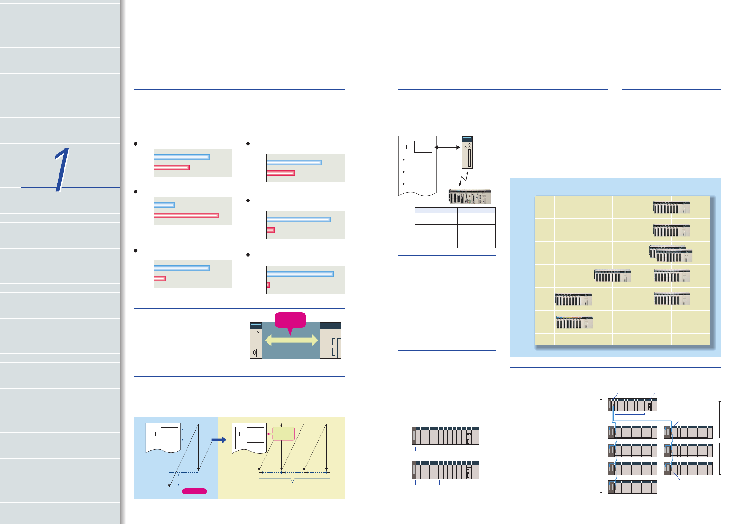
Faster Instruction Execution and Faster Overall Performance
In addition to further improvements to
the instruction execution engine, which
is the core of overall PLC performance,
the high-speed RISC chip has been
upgraded to realize the fastest
instruction execution performance in
Common Processing: 1.6 Times Faster
Previous CS1
models
New CS1
models
The figures above are for high-speed, general-purpose PLCs with
interchangeable boards.
0.3 ms
0.5 ms
PCMIX Value: 3 Times Higher
Previous CS1
models
New CS1
models
The PCMIX is the average number of instructions that can be
executed in 1 µs and expresses the over execution performance of
the ladder program. This unit was conceived to allow comparing
the performance of PLCs from different manufacturers using a
common metric.
Cycle Time: 2.5 to 4.8 Times Shorter
(Cycle time for 128 inputs and 128 outputs)
Previous CS1
models
New CS1
models
With normal I/O refresh, 1-ms pulses are not lost even for largecapacity (e.g., 30-Kstep) programs. This allows use in applications
requiring a high working accuracy, such as molding equipment.
5
16
8 Ksteps/ms
Basic instructions only: 38 Ksteps/ms
Including special instructions:
22 Ksteps/ms
System Bus Baud Rate Doubled
The data transfer rate between the CPU
Unit and certain Units has been
doubled to further improve total system
performance.
the industry. Also, the new models
have a mode where instruction
execution and peripheral processing are
processed in parallel, enabling balanced
improvements in overall speed.
LD Instruction Processing Speed:
2 Times Faster
Previous CS1
models
New CS1
models
The development of a special LSI to execute instructions and use
of a high-speed RISC chip enable high-speed processing at the
CPU.
20 ns
OUT Instruction Processing Speed:
8 Times Faster
Previous CS1
models
New CS1
models
Programs consisting mainly of basic instructions are processed at
ultrahigh speed.
20 ns
Subroutine Processing Speed:
17.6 Times Faster
Previous CS1
models
New CS1
models
Cycle time overhead due to program structuring is minimized.
2.1
µ
s
Baud rate
doubled
System bus
CS1 Basic I/O Units
CS1 Special I/O Units
CS1 CPU Bus Units
Reduced Variation in Cycle Time During Data Processing
Instructions that require long execution
time, such as table data processing
instructions and text string processing
instructions, are processed over
Table data/
text string
processing
Long
Long
execution
execution
time
time
The cycle is temporarily
extended when the instruction
is executed.
Variation
multiple cycles to minimize variations in
cycle time and maintain stable I/O
response.
Table data/
text string
processing
Only start of
processing
designated.
Background processing performed over several
cycles to limit the impact on cycle time and thus
reduce variation in cycle time.
40 ns
170 ns
CPU Unit
37 µs
Improved Refresh Performance for Data Links,
Remote I/O Communications, and Protocol Macros
In the past, I/O refresh processing with
the CPU Bus Unit only occurred during
I/O refresh after instructions were
CPU Unit
DLNK
CIO Area words
allocated to CPU
Bus Units
DM Area words
allocated for CPU
Bus Units
Specific Area for
CPU Bus Units
Controller Link Unit
DeviceNet Unit
Serial Communications
Unit
Ethernet Unit
Immediate
I/O refresh
n
CPU Bus
Unit n
Data exchange
during communications cycle
Refresh functionUnit name
Data links
Remote I/O
Protocol macros
Socket service based
on manipulation of
specific bits.
executed. With the new CS1, however,
I/O can be refreshed immediately by
using the DLNK instruction. Immediate
refreshing for processes peculiar to the
CPU Bus Unit, such as for data links and
DeviceNet remote I/O communications,
and for allocated CIO Area/DM Area
words when instructions are executed,
means greater refresh responsiveness
for CPU Bus Units.
Product lineup (Example: LD instruction processing speed, DM capacity)
Program
Capacity
250 Ksteps
120 Ksteps
60 Ksteps
Large Capacity CPU Units for
Greater Component Control
Power
The CS1 CPU Units boast amazing
capacity with up to 5,120 I/O points, 250
Ksteps of programming, 448 Kwords of
data memory (including expanded data
memory) and 4,096 timers/counters
each. With a large programming
capacity, CS1 PLCs are not only ideal
for large-scale systems but easily
handle value-added applications and
other advanced data processing.
30 Ksteps
20 Ksteps
(LD: 0.04 µs, DM: 64 Kwords)
10 Ksteps
(LD: 0.04 µs, DM: 64 Kwords)
Control Up to 960 Points with
Units Mounted to the CPU Rack
The CS1 provides a high level of space
efficiency. As many as 960 I/O points
can be controlled by simply mounting
ten Basic I/O Units, with 96 I/O points
each, to the CPU Rack. Alternatively, as
many as 80 analog I/O points can be
used by mounting five Analog Input
Units and five Analog Output Units.
Ten I/O Units of 96 points each
Five Analog Output
Units of 8 points each
Five Analog Input Units of
8 points each
Two Series of Expansion Racks Up to 50 m Long for
Long-distance Expansion with Up to 72 Units and 7 Racks
With an expansion capacity of up
to 80 Units and 7 Racks over a
distance of 12 meters, the CS1 can
meet large-scale control needs.
Alternatively, an I/O Control Unit
and I/O Interface Units can be used
to connect two series of CS1 Longdistance Expansion Racks
extending up to 50 m each and
containing a total of up to 72 Units
and 7 Racks. CS1 Basic I/O Units,
CS1 Special I/O Units, and CS1
CPU Bus Units can be mounted
anywhere on the Racks and
programmed without being
concerned about special remote
programming requirements.
Note: C200H Units cannot be mounted on the Longdistance Expansion Racks.
Wide Lineup Makes It Easy to
Build the Optimum System
A total of nine CPU Unit models
provide for a wide range of applications,
from small-scale systems to large. The
lineup also includes Memory Cards,
Serial Communications Boards, and a
wide selection of Special I/O Units that
can be used with any CPU Units to
flexibly build the system that meets the
requirements.
(LD: 0.02 µs, DM: 448 Kwords)
(LD: 0.02 µs, DM: 256 Kwords)
(LD: 0.02 µs, DM: 128 Kwords)
(LD: 0.04 µs, DM: 128 Kwords)
(LD: 0.04 µs, DM: 64 Kwords)
960 pts 1,280 pts 5,120 pts
I/O Control Unit
9 Units
50 m
(LD: 0.02 µs, DM: 64 Kwords)
(LD: 0.02 µs, DM: 64 Kwords)
Number of I/O points
CPU
2 Series of
Expansion Racks;
Up to 7 Racks Total
I/O Interface Unit
Terminating
Resistor
50 m
4
5
Equipped with functions demanded by the production site to
suit a variety of applications.
The evolution of
the SYSMAC CS1 is
accelerating advances in
the production site.
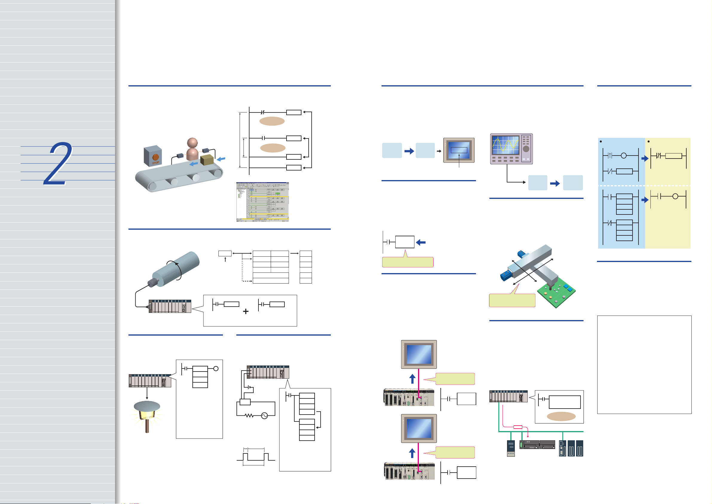
Nested Interlocks (for CPU Unit Ver. 2.0 or Later)
Although strictly speaking the present
interlock instructions do not allow
nesting, applications can be created to
include combination of complete and
partial interlock conditions that achieve
nested interlocks.
Emergency
stop button
(1) Conveyor operates
(2) Contact "a" turns ON when operator is present and
products are supplied.
(3) When the emergency stop button is pressed, the
conveyor and product addition both stop.
Operator
Contact a
Product added
by contact a
CX-Programmer Screen
Emergency
stop button
Conveyor
operates
Worker present (a)
Product
added
Easy Cam Switch Control with Ladder Instructions
(for CPU Unit Ver. 2.0 or Later)
Cam switch
Absolute
encoder
Parallel
wiring
Easy Calendar Timer Function
(for CPU Unit Ver. 2.0 or Later)
=
DT
Compares two
dates/times Comparison
can be limited to any
combination of years,
months, days, hours,
minutes, or seconds.
Example:
A calendar timer function
can be easily set up to
start a process at exactly
Turn ON at 5:00
every evening
5:00 every evening.
Angular data
Value
converted by
GRY
instruction
GRY
Gray code converted
into binary, BCD, or
angles.
TIME-PROPORTIONAL
OUTPUT (TPO) Instruction
(for CPU Unit Ver. 2.0 or Later)
Comparison table Output
Upper limit Lower limit
Compared using
BCMP2 instruction
BCMP2
Compared to see whether
data is between upper
and lower limits.
SSR
20 % 80 %
1 s
Time-proportioning PID
control can be handled
by the PLC by combining
the PID and TPO
(TIME-PROPORTIONAL
OUTPUT) instructions.
MILH 0
MILH 1
MILC 1
MILC 0
Support Software
clearly shows the
interlock status.
ON
OFF
OFF
ON
OFF
The time interval
for execution by
the GRY
instruction is
determined by the
response speed
for reading data
from the absolute
encoder.
PID
S
C
D
TPO
S
C
B
Manipulated variable
Convert Between Floating-point Decimal and Character Strings
The new CS1 can convert floating-point
decimal (real numbers) to character
strings (ASCII) for display on a PT
(operator interface). The data can be
displayed on the PT as a characterstring display element.
Conversion instruction
Floatingpoint
decimal
E.g., 500.00 353030E23030
Character
string
Character-string
display element
PT
500.00
PID Autotuning
The new CS1 can autotune PID
constants with a PID control instruction.
The limit cycle method is used for
autotuning, so the tuning is completed
quickly. This is particularly effective for
multiple-loop PID control.
PIDAT
PID control instruction with
autotuning
Autotuning for PID constants
The new CS1 can convert ASCII
character strings read from
measurement devices by serial
communications to floating-point
decimal data for use in data processing.
Measurement device
(example)
Conversion instruction
Serial
communications
Character
string
Floatingpoint
decimal
Highly Accurate Positioning
with XY Tables
The new CS1 has many doubleprecision processing instructions for
floating-point decimal operations,
enabling positioning with greater
accuracy.
Error Status Generation for
Debugging
A specified error status can be
simulated by executing the diagnostic
instructions (FAL/FALS). With the new
CS1, debugging is simple for
applications that display messages on a
PT or other display device based on the
error status of the CPU Unit.
(Example)
An error has
occurred at unit
number xx.
There is a
possibility that
rack number xx
is disconnected.
PT
Error in Special I/O
Unit
FAL
PT
I/O bus error
FALS
Floating-point
decimal instruction
High-precision positioning
Easy Reading of Maintenance
Data via DeviceNet
(for CPU Unit Ver. 2.0 or Later)
The addition of special explicit message
instructions makes it easy to send
explicit messages without having to
consider FINS commands. Transferring
data among PLCs with explicit
messages is also simplified.
Special explicit
message instruction
No need to
consider FINS
DeviceNet
Simpler Ladder Programs
Ladder programs that use a lot of basic
instructions can be simplified using
differentiation instructions LD NOT,
AND NOT, and OR NOT, and
instructions that access bits in the DM
and EM Areas.
With CS1-series PLCsWith other PLCs
a
a
a
ORW
D00000
#0001
D00000
a
ANDW
D00000
#FFFE
D00000
OUTB
D00000
#0000
Binary Set Values for
Timer/Counter Instructions
The SV for a timer or counter
instruction can be specified using either
BCD or binary. Using binary SV enables
longer timers and higher-value
counters.
Examples: Timer/Counter Instructions
TIM (BCD): 0 to 999.0 s
TIMX(550) (binary) 0 to 6553.5 s
CNT (BCD): 0 to 999 counts
CNTX(546) (binary) 0 to 65,535 counts
Applicable Timer/Counter Instructions
TIMER: TIMX(550)
COUNTER: CNTX(546)
HIGH-SPEED TIMER: TIMHX(551)
ONE-MS TIMER: TMHHX(552)
ACCUMULATIVE TIMER: TTIMX(555)
LONG TIMER: TIMLX(553)
MULTI-OUTPUT TIMER: MTIMX(554)
REVERSIBLE COUNTER: CNTRX(548)
RESET TIMER/COUNTER: CNRX(547)
6
7
Easier and more efficient design, developmen t, and maintenance with
Windows-based software and middleware.
The evolution of
the SYSMAC CS1 is
accelerating advances in
the production site.
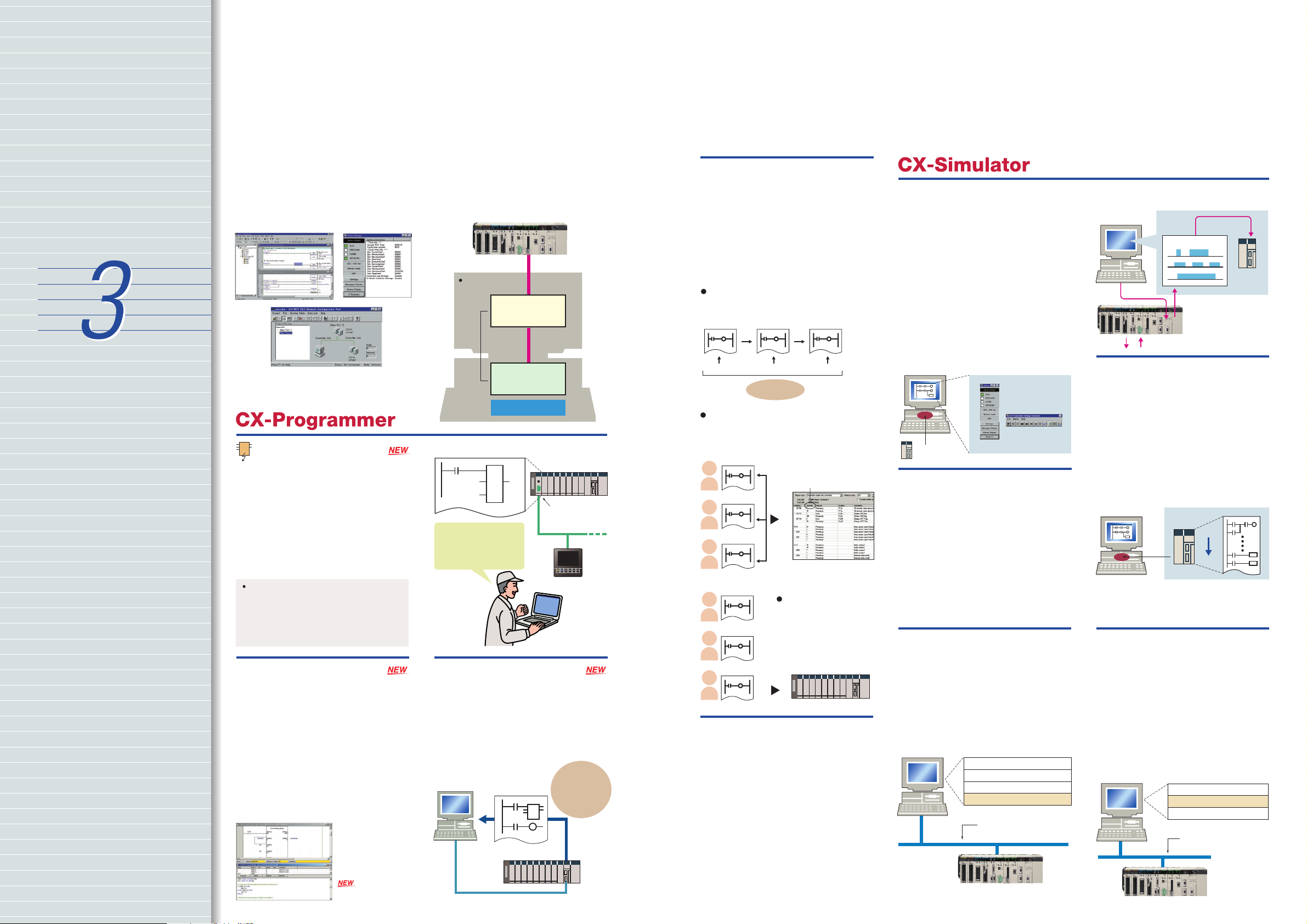
Improved Support Software for an Integrated
Windows-based Development Environment
More efficient design and development using the CX-Programmer for programming
and network configuration, and CX-Simulator for operation simulation.
CX-Programmer CX-Simulator
CX-Net Network Configuration Tool
FB
OMRON FB Library
(Unit Ver. 3.0 or later)
The OMRON FB library provides
function blocks for setting SPs, reading
PVs, and reading/writing RUN/STOP
status and other Temperature Controller
parameters. The programmer simply
pastes function blocks from the OMRON
FB Library into the ladder program. The
desired functions can be utilized simply
by inputting the Temperature Controller
unit number and address.
What is the OMRON FB Library?
The OMRON FB Library is a set of functional objects for
ladder programming for OMRON CS/CJ-series PLCs. By
incorporating the OMRON function blocks provided by
OMRON into a ladder program, the program interface for
different control devices is easily completed. This reduces the
number of working hours required for program development
and, at the same time, improves product quality through
standardization.
The Structured Text (ST)
Language Enables Trigonometric
Functions and other Arithmetic
Processes
In addition to ladder programming,
function block logic can be written in ST,
which conforms to IEC61131-3. With ST,
arithmetic processing is also possible,
including processing of absolute values,
square roots, logarithms, and
trigonometric functions (SIN, COS, and
TAN). Processing difficult to achieve in
ladder programs becomes easy to write.
(Unit Ver. 3.0 or later)
System PLC
CS1
Online connection
Inside the personal
computer
CX-Programmer
(Programming
software)
Integrated
development
environment
(Virtual CPU Unit)
Example: Function Block for Writing Temperature Controller SPs
Temperature
Controller
unit number
Address
Simply paste a function block
from the OMRON FB Library
into the ladder program and
enter the unit number, set
point, and other parameters.
Online connection
CX-Simulator
Windows
Normal
end
SYSMAC CJ-series PLC
(See note.)
DeviceNet
Master Unit
DeviceNet
Temperature
Controller
Recovery Possible by
Uploading Function Blocks
from Working PLC
Programs with function blocks can be
uploaded from CPU Units, just like
normal programs, without the need for
additional memory, such as a Memory
Card.
CX-Programmer
Ver.5.0
FB
CS/CJ-series
Unit Ver. 3.0
(Unit Ver. 3.0 or later)
Programs with
function blocks
can be uploaded
from working
PLCs.
Enhanced Efficiency for
Program Development Teams
(for CPU Unit Ver. 2.0 or Later)
Multiple programmers will enjoy better
efficiency when working on task-based
programs, thanks to automatic
checking for address duplication
among tasks, downloading and
uploading in task units, and easy
monitoring of task operating status.
The execution status of each task can be
monitored with CX-Programmer to improve
debugging efficiency.
Task 1
Executing
Checking for address duplication among
tasks developed by multiple programmers is
automatically executed with the cross
reference report of CX-Programmer.
Download only the revised tasks.
Task 1
Executing
Monitoring with
CX-Programmer
When development is
done by several people,
only the tasks that have
been revised need to be
downloaded from CXProgrammer.
Task 1
Executing
The report shows that this
address is used in the
program in the right
column, and tells how
many times it is used.
CX-Programmer list of
Check for duplicate addresses
duplicate addresses
Copy and Paste between
Spreadsheets and Symbol Tables
You can use your favorite spreadsheet
application to prepare an allocation
table with symbol names, addresses,
and I/O comments, then copy and paste
it into a symbol table, and also do the
reverse. This greatly improves
programming productivity.
Programs Can Be Executed,
Monitored, and Debugged
without an Actual PLC
The CX-Simulator Software simulates
ladder execution of the new CS1 CPU
this data to the CX-Simulator as virtual
external input data.
CX-Simulator
Virtual external
input
Sequential data
Unit on a computer. Online functions,
such as monitoring of I/O bit status,
monitoring of I/O memory present
values, forced set/reset, differential
Virtual
CPU Unit
monitoring, data tracing, and online
editing, can be performed by connecting
to the virtual CPU Unit on the computer
from the CX-Programmer using the CX-
Actual PLC
CS1
Simulator. This reduces the total lead
time to machine or system startup.
CX-Simulator
System status
setting window
Comprehensive Debugging
Functions Including Ladder
Step Execution and Break Points
The new CS1 has comprehensive
debugging functions, including ladder
Debugging console
Virtual
CPU Unit
window
Data Logging On-site and
Operation Verification in the
Office
Sequential data from I/O memory in the
actual PLC can be obtained and saved
step execution (execution by instruction),
start point settings, break point setting,
I/O break conditions, and scan execution.
This enables more detailed debugging
without using an actual PLC. Interrupt
tasks can be simulated, enabling more
realistic debugging.
Virtual
CPU Unit
Start
as a data recreation file (CSV format).
On-site PLC ladder execution can be
recreated on a computer by inputting
Stop
Middleware to Support PLC-centered System Construction
Easy development of user applications for communications with the new CS1.
SYSMAC Compolet:
Accessing the CS1 with
Visual Basic
Use SYSMAC Compolet for
communications with OMRON PLCs to
greatly reduce development time of
user applications for CS1 I/O memory
read and write, forced set/reset, and
FINS message communications using
Visual Basic.
Visual Basic user application
Compolet
Fins Gateway
Network board or port
Network support: Controller
Link, Ethernet, or RS-232C
serial communications
CS1
PLC Reporter 32:
Add-on Software for Accessing
the New CS1 Using Excel
Use PLC Reporter 32 to automatically
collect specific CS1 I/O memory data
into Excel 97 or Excel 2000 cells without
special programming. Basically, a
system can be constructed with a
computer, PLC Reporter 32, Excel, and a
host link cable. The cost of constructing
a monitoring system can thus be greatly
reduced.
Excel
PLC Reporter (Fins Gateway)
Network board or port
Network support: Controller
Link, Ethernet, or RS-232C
serial communications
CS1
CX-Programmer Ver. 5.0 or
8 9
higher is required.

Further improvements to communications f unctions.
Seamless networks increase production site transparency.
The evolution of
the SYSMAC CS1 is
accelerating advances in
the production site.
The Solution for Communicating
across Network Levels
The SYSMAC CS1 enables FINS
message communications across a
maximum of eight levels (See note)
(using CX-Programmer Ver. 4.0 or
higher) in comparison with three levels
in previous OMRON systems
Expansion up to eight levels lets you
build a seamless communications
system for sending FINS messages
across multiple levels of Ethernet and
Controller Link networks.
Note: For CPU Unit Ver. 2.0 or later.
A Wide Range of Systems,
from Small-scale to Large
OMRON offers a full lineup of reliable
PLCs including the "flagship" CS1
Series, and ranging from the smallscale CQM1H to the large-scale CV
Series. The CS1 Series meets the needs
not only of small-scale to large-scale
systems, but of distributed systems as
well. This allows the construction of the
optimum system for the scale and
applications of the production site.
Flexible System Building
Based on the DeviceNet
The CS1 Series supports the worldwide
multivendor bus standard, DeviceNet.
Component connections in a
multivendor environment are greatly
enhanced by connecting to up to 64
nodes for a wide range of FA
applications, and by device profiles and
configurator tools that ensure high
reliability and easy maintenance.
Production systems can be configured
even more flexibly by incorporating
products such as the MULTIPLE I/O
TERMINAL.
Functions for Better Ethernet
Support
Ethernet is becoming an increasingly
important standard for information
networks. Up to eight socket interfaces
for TCP/IP and UDP/IP are supported, in
addition to FINS messages, FTP file
transfers, and mail notification, so that
production management can now be
organically linked with the production
site.
High Event Responsiveness and High-speed Instruction Execution
The new CS1 has an operating mode
that allows parallel processing for
program execution and peripheral
services. This has the following benefits.
Fast exchange with host computers of
large amounts of data, without
dependence on the program capacity of
the new CS1.
Smooth refreshing of data exchanged
with SCADA software without variations
in timing.
Cycle time not affected if communications
traffic or networks increase when
expanding facilities in the future.
Normal mode Parallel processing mode
(Instruction execution)
Host
SCADA software
CS1
(Peripheral servicing)
Peripheral servicing
Fast large-volume data
exchange
No variations in data
exchange timing
Peripheral services
independent from
cycle time.
Cycle time
Response time:
Approx. 1/3
Sending/receiving FINS
commands and other
event processing.
Add a Redundant Optical Ring
to Your Controller Link
Communications
A redundant network configuration will
keep communications flowing over the
duplicate ring-shaped path in the event
of a broken optical fiber, preventing
system malfunction.
Head office, remote office,
home, business trip destination
• CX-Programmer
Modem
FINS message
Email
Information network
CS1
Ethernet Unit
• TCP/IP or UDP/IP socket service
• FINS message communications
• Message client (SMTP) function
• FTP server function
(File read/write to Memory Card)
Controller Link
FINS message
Seamless
Controller network
Controller Link Unit Controller Link Unit
FINS message
Remote Monitoring via the Web
Connecting via an ONC enables remote
monitoring from a Web browser with a
user-defined Web application (using
Web Tool Kit). It is also possible to
automatically collect data on a Memory
Card mounted to an ONC and
automatically transfer data to the host
PLC (using Data Collection/Distribution
Software).
Head office or remote office
• Web browser
• CX-Programmer
Public telephone line
Modem
Serial communications
Data links
CS1
FINS message
DeviceNet
Ethernet
(Intranet)
DeviceNet
Configurator
DeviceNet
Unit
RS-232C
CS1
Remote I/O communications
ONC
Internet
Head office,
remote office,
home, business
trip destination
• Web browser
Email
HTTP/socket
Automatic FTP transfer of
collected data
Open Network Controller
• Web server function
• Email client (SMTP)
• FTP client
(Collected data file
transferred to host using
FTP when transfer
conditions are met.)
• FINS message
communications
CS1
CJ1
10
I/O refresh
Peripheral service
Peripheral services cannot
be executed
than cycle time.
in shorter period
I/O refresh
Can be executed
in shorter period
than cycle time.
Parallel processing
Event services with
Special I/O Units, CPU
Bus Units, and Inner
Boards.
Peripheral and RS-232C
port servicing.
Event services using
Communications Board.
CS1
Component network
DeviceNet Unit
(can operate as
master or slave)
Temperature
Controller (PID and
other parameter
settings possible
from the
DeviceNet
Configurator).
DeviceNet Slave
DRT2-series Series
Robot or
other device
Programmable
Slave
CompoBus/S
11

Construction of systems in multivendor env ironments simplified
with protocol macros.
The evolution of
the SYSMAC CS1 is
accelerating advances in
the production site.
Serial Gateway
(CPU Unit Ver. 3.0 or later)
(Serial Communications Units/Boards with Ver. 1.2 or later)
Truly Seamless Incorporation of OMRON Components
and Other Devices into Networks
When the CPU Unit (Ver. 3.0 or later) or
Serial Communications Board or Serial
Communications Unit (Ver. 1.2 or later)
receive a FINS command containing a
CompoWay/F command (see note 1) via
network or serial communications, the
command is automatically converted to
a protocol suitable for the message and
forwarded using serial communications.
CompoWay/F (See note 2.)
Host Link FINS
(Possible only with Serial Communications Boards or
Serial Communications Units Ver. 1.2 or later)
Serial Gateway System (Reference)
When CompoWay/F commands are
enclosed in FINS commands and sent
to Serial Communications Boards or
Serial Communications Units (Ver.
1.2) or serial ports on CPU Unit Ver.
3.0, the enclosed CompoWay/F
command is retrieved using a Serial
Gateway Function and sent as a
CompoWay/F command.
More Ports for Even More
Serial Device Connections
Protocol macros make it easy to create
serial communications protocols
(communications frames, error checks,
retries, error processing, etc.) to match
those of remote communications
devices. Multiple ports are provided for
this function. Each PLC supports up to
16 Serial Communications Units (32
ports total) and one Serial
Communications Board (with 2 ports).
This makes it possible to connect up to
34 devices with serial communications
at a speed of 38.4 Kbps. Message
length has been increased from 256 to
1,000 bytes to give communications
more power than ever before.
Gateway
Serial
Component/PLC
Note 1: FINS
Abbreviation for Factory Interface Network Service. A
command system for message services common to
OMRON networks. FINS commands can be sent across
up to 8 network levels, including serial
communications paths using a serial gateway.
(Possible only with CS/CJ-series CPU Unit Ver. 2.0 or
later.)
Note 2: CompoWay/F
CompoWay/F is an integrated communications
protocol used for OMRON general-purpose serial
communications. It is used by Temperature Controllers,
Digital Panel Meters, Timer/Counters, Smart Sensors,
Cam Positioners, Safety Controllers, etc. (as of July
2004).
Temperature
Controller
OMRON Components
communications
Windows-based Software
Simplifies Serial Device
Connections
Protocol macros for Serial
Communications Units and Boards can
be created using the CX-Protocol, thus
enabling message tracing and greatly
reducing the time involved in
connecting various serial devices.
FINS network
FINS command received
Serial Gateway: FINS
command "capsule"
opened and contents
retrieved.
Sent as a CompoWay/F
command
Smart Sensor
Enhanced Protocol Macro
Functionality
(Serial Communications Units/Boards with Ver. 1.2 or later)
Baud rate increased from 38,400 bps
to 57,600 bps for faster
communications.
Standard system protocol added for
greater connectability with
components and PLCs.
•CompoWay/F Master
•Host Link Master functions
•Mitsubishi Computer Link Master
Wide Range of Applicable
Protocols Allows for High
Value-added Programs
The CS1 Series supports a wide range
of serial communications protocols,
such as Host Link, no-protocol, NT Link,
peripheral bus, and more. These allow
for high value-added programs such as
MMI, communications, and data
processing.
The Fastest Communications
in the Industry with
High-speed NT Links
Combine with one of the NS Series
Programmable Terminals (NS8, NS10,
or NS12) to enable connecting Highspeed NT Links. Using NT Link
terminology together with a
communications speed of 115 Kbps
provides high-speed response.
NT Links (1:N Mode)
Programmable
Terminal
PLC-to-PT connection in NT Link (1:N mode) communications can be either one-to-one or one-to-many.
Programmable
Terminal
Serial Communications
Configuration Example
Host computer, etc.
Host Link
ASCII Unit Serial Communications Unit
Commercially-available
external device
General-purpose protocol
using BASIC in ASCII Unit
Protocol macros
Temperature controller,
bar code reader, etc.
Serial
Communications Board
CPU Unit
Protocol macros
Commercially-available
external device
Protocol macros
Microcomputer,
etc.
Host Links No-protocol
Sending Host Link and
FINS commands
Reading and writing
Device
of I/O memory and
operating modes
Response
Serial
Communications
Unit
TXD instruction
or
RXD instruction
using Serial
Communications
Unit
Data input from
a bar code reader
Supports No-protocol Communications
(Serial Communications Units/Boards with Ver. 1.2 or later)
No-protocol communications supported for Serial
Communications Units and Serial Communications
Boards
This mode enables components to be connected to
multiple communications ports using no-protocol
communications.
Serial port I/O instructions executable using noprotocol communications from Serial
Communications Units and Serial Communications
Boards (TXDU, RXDU, TXD, and RXD) are
supported for CPU Units with Ver. 3.0 or later.
Programming Devices
CX-Programmer
CX-Protocol
CX-Motion
Data output to printer
Programming
Console
Peripheral bus
(Programming
Console bus)
Programmable
Terminal
NT Link
Non-OMRON
PLCs, etc.
CPU Unit
RS-232C Port
Serial
Communications
Board
TXD instruction
or
RXD instruction
using CPU Unit's
RS-232 port or Serial
Communications Board
12 13

Advanced management and resource inheri tance providing powerful support for
maintenance and operation.
The evolution of
the SYSMAC CS1 is
accelerating advances in
the production site.
Remote Maintenance
1. Program or monitor a
remote PLC via a modem
connection.
2. Program or monitor a
network PLC via a Host
Link connection.
3. Send e-mail for errors
from PLCs connected to
Ethernet.
1. Remote programming/monitoring
via modem
Note: The same kind of programming and monitoring
performed via normal Host Link is possible.
(See note.)
Modem
Memory Cards for Data File
Management
User programs, I/O memory, or system
parameters can be converted to
Windows-based files and stored in
Memory Cards or in EM file memory in
the CPU Unit. It is also possible to
automatically read the user program
and other data from the Memory Card
to the CPU Unit at startup, replacing
ROM operation. Change programs onsite using only a Memory Card and
Programming Console, or use Memory
Cards to store symbol tables or I/O
comments. Connecting a Programming
Device allows monitoring operations
with ladder programs with comments.
It is also possible to save and read data
such as DM data to a Memory Card
during operation, and the Memory
Cards are ideal for operations such as
saving quality data and reading recipes.
3. Mail
Phone line
Office
PC Card
Adapter
Memory Card
Ethernet
Modem
Host Link
2. Remote programming/
monitoring via Host Link
(See note.)
Upload
Download
Boost Program Security
by Keeping Part of It Hidden
(for CPU Unit Ver. 2.0 or Later)
You can prevent access to special tasks
by requiring the user to have a
password to read them.
Task 1
Use a password to prevent
reading of only task 2.
CX-Programmer
Ver. 4.0
Task 2
Task 3
Crucial
programming
cannot be
read.
This allows you to hide crucial parts of
the program.
By applying write protection, you can
also prevent a user from inadvertently
writing over the hidden part of the
program. This provides additional
protection for your program.
Read protection
Write protection
Internal Flash Memory-based
Battery-free Operation
Flash memory (non-volatile memory) is
built into the new CS1's CPU Unit. User
programs and system parameters (e.g.,
PC Setup and data link tables) are
automatically saved to this flash
memory. This means that the new CS1
can operate without a Memory Card
and battery.
Built-in flash memory
User program
Parameter area data
CS1
Prevent Information Leaks
from PLCs
(for CPU Unit Ver. 2.0 or Later)
In addition to applying read protection
functions to the user program area and
tasks, you can also protect against the
transfer of user programs to a Memory
Card.This prevents leaks of proprietary
information by completely protecting
against the reading of programs inside
the PLC.
Read
protection
CX-Programmer
Ver. 4.0
No transfer
possible
Memory Card
Easy Replacement of Existing
Models
Programs designed for existing models
(C200HX/HG/HE, CVM1, or CV-series
PLCs) using the CX-Programmer can be
converted for use with the new CS1.
The following functions are available to
make the conversion to the new CS1
even easier.
CV-CS address conversion instruction to
convert programs designed for the
CVM1/CV that include internal I/O
memory addresses.
C200HX/HG/HE: Region comparison (ZCP
and ZCPL) instructions.
C200HX/HG/HE
CVM1/CV
Easy replacement
CS1
Write Protection from a Specific
Node over the Network
(for CPU Unit Ver. 2.0 or Later)
You can now stop specific nodes from
writing over the network.By preventing
unintentionally writes to the PLC while
monitoring data over the network, you
can prevent potential problems.
Reading
possible
Write protection
Reading
possible
Write enabled
Replace Malfunctioning Units
without Turning OFF the Power
(Online Unit Replacement)
When an I/O Unit, a Special I/O Unit, or
a CPU Bus Unit is malfunctioning, it is
now possible to replace the faulty Unit
while the system continues operating.
This is particularly effective for systems
that cannot be stopped when a problem
has occurred in another part of the
system.
(This function requires a CS1D-CPU S CPU
Unit, a CS1D-BC082 or CS1D-BI092 Backplane,
and a CS1D-PA207R or CS1D-PD024 Power
Supply Unit.)
(1) (2)
Remove the
faulty Unit
after
stopping
access to it.
Faulty Unit
CPU
PS
Resume
access after
replacing the
Unit.
14
Production
site
Programming
Console
Battery-free
operation
with no Memory
Card.
CX-Programmer Ver. 5.0 or higher required.
Store All I/O Comments, Symbol Names, Rung Comments,
and Other Information in CPU Unit Comment Memory
(Unit Ver. 3.0 or later)
When downloading projects, the
Memory Card, EM file memory, or
comment memory (in the CPU Unit's
flash memory) can be selected as the
transfer destination for I/O comments,
symbol names, rung comments, and
other data. This enables data such as
I/O comments, symbol names, and
rung comments to be stored in the CPU
Unit's internal comment memory when
a Memory Card or EM file memory are
both not available. (PLC models: CS/CJseries with unit version 3.0 or later
only.)
15

Machine performance improved with
high-speed, high-precision motion control.
The evolution of
the SYSMAC CS1 is
accelerating advances in
the production site.
Position Control Units
Two Types of Outputs and
Control of 1, 2, or 4 Axes
Select from 1-axis, 2-axis, and 4-axis
models with either open-collector
output or line-driver output to suit a
number of different applications.
A Variety of Positioning
Functions
There are 2 operating modes: direct
operation (position, speed, acceleration,
and deceleration data specified from
the ladder program), which is effective
for setting target positions and speeds
immediately or during operation, and
memory operation, where fixed
patterns are stored beforehand in the
Unit and used for operation. There are
also a variety of positioning functions,
such as interrupt feeding, which is
effective for feeder control, and forced
interrupt, which is useful in
emergencies.
Advanced Motion Control Units
Easy System Construction
Up to 30 physical axes and two virtual
axes, making a total of 32, can be
controlled, and the servo interface is
handled by high-speed servo
communications (MECHATROLINK-II, a
registered trademark of Yaskawa
Electric Corporation). This makes it
possible to control multiple axes with
less wiring.
Easy Data Control
High-speed servo communications lets
you read programs and parameter
settings from CX-Programmer on a PC.
You can also read and track the
operating status of parameter settings
inside the Servo Driver.
Easy Motion Control
Motion control, including positioning,
synchronizing (electronic gears,
electronic cams, tracking), speed, and
torque control, can all be handled by
the CS1.
Eight motion tasks can be used for
simultaneous motion program
execution.
Motion Control Units Customizable Counter Units
Easy Programming with
G Language and Multitasking
The Motion Control Units use G
language to ensure easy programming.
The Units have a large programming
capacity of up to 100 programs and
2,000 program blocks, and allow
independent operation of 4 tasks.
High-speed Interlocks
Interrupt programs can be executed
from the motion control program using
D codes (interrupt codes). Easy, fast
interlocks ensure greater production
efficiency.
Motion
Control
Units
Communications
SMART
STEP
Units
Pulses
JUSP-NS115
Interface Unit for
MECHATROLINK-II
(Yaskawa)
A Whole New Concept
A high-speed PLC with 20 I/O points, a
2-axis high-speed counter, and 2 pulse
or analog outputs have all been
combined into 1 Unit. The
Customizable Counter Units allow easy
execution of complicated applications.
Customizable
Counter Unit
PLC
High-speed
PLC
overhead
0.1 ms
Customizable Counter UnitsPosition Control
Analog
W Series
20 I/O points
Pulse output
Analog output
Analog input
Counter
Encoder
Easy Control for Bending and
Pressing
It is possible to switch between speed
control and torque control from the
ladder program, enabling bending
operation for metals and pressing
operation for bonding.
Pulse/analog output
CX-Programmer
Servo Driver
Torque
Speed
CX-Motion
CX-Position
MC-Miel
(free software)
Torque Sensor
CS1W-HCA22
Torque Speed
Position
Servomotor
Analog input
Servo Driver
Synchronous Control with
Electronic Cam
Counter input and pulse output that
previously could only be connected via
a CPU Unit can now both be handled by
the same Unit. The built-in high-speed
PLC enables synchronous control of, for
example, electronic cams. The cam
curve that determines the relationship
between counter input and pulse
output can be defined freely using the
line-segment approximation function
from the ladder program.
Design Costs Reduced by
Modularization
Ladder programs and I/O instructions to
be re-used or shared by designers can
be transferred from the main CPU Unit
to the Units, allowing "modularization"
that helps to reduce design costs. Up to
96 Units can be used, enabling easy
system expansion in the future.
Motion Applications with
High-speed Response
A wide range of interrupt functions and
superior response performance enable
motion applications requiring highspeed response using pulse I/O.
16
ServomotorServomotorServomotorServomotor
17

Smart Process Control
OMRON PLC-based Process Control brings Major Innovations to Process Automation
The evolution of
the SYSMAC CS1
accelerates DCS
downsizing.
Function block programming
Sequence programming
using either step ladders or
sequence tables
A direct link to HMI products
DCS functionality in a PLC
Analog Units with signal
conversion functions
A scaleable system
configuration
PLC-based
PLC-based
Process Control
Process Control
Duplex
operation
supported
Complete
maintenance
functions
Diversified Loop Control is even easier to use.
Programming becomes even easier with function-block programming.
Packed with complete DCS functionality,
the LCBs/LCUs are programmed with
function blocks designed specifically for
process control. Similar to preparing a
flow sheet, function blocks are pasted
and connections made using a graphic
interface. A wide array of control
methods, from basic PID control to
cascade and feed-forward control, are
possible.
Example: Cascade Control
(Heating and Cooling)
Temperature
Analog
Input Unit
Analog
Output Unit
Cooling
water
Drain
Loop Control
Unit/Board
PV1
PV2
Split
conversion
Temperature
PID1
PID2
Heat
exchange
MV2
MV1
RSP1
Steam
With Function
Blocks:
Isolated-type
Ai4 Terminal
Y1
Y2
Y3
Y4
PID1
Basic PID
PV
PVE
RSP
MIE
MVE
Basic PID
PV
PVE
RSP
MIE
MVE
PID2
Split
Conversion
SP
Y1
MV
SP
Y1
MV
X1
Isolated-type
Ao4 Terminal
Y1
Y2
X1
Y1
X2
Y2
X3
Y3
X4
Y4
Provides an exceptionally open environment with PLC-based
process control to advance standardization and IT integration of
the process control system.
Operation, Monitoring, and Data Logging
Touch Panels
NS-series PT
PLC Reporter
PLC data can be collected
and written in Excel.
Compolet
Communications
programming
between a PC and
PLC can be
accompllshed
easlly with ActiveX
control.
User Application
PLC (CS1 Duplex)
CS1D Process-control CPU
Unit
Duplex Process-control CPU
Unit can help reduce risk
insystems that must not stop.
Process I/O Units
Analog I/O Units are available
for diverse functions such as
Isolators, power supplies, and
signal conversion.
Special HMI software
CX-Process Monitor Plus
Commercially available
HMI software
HMI software
compatible with
FinsGateway
Ethernet/Controller Link
PLC (CS-series)
HMI Software
Loop Control Board/Unit
Condenses DCS functions
in a compact Unit and
enables function-block
programming.
CX-Process Tool
Function blocks can be
pasted into windows and
graphic programming can
be perfomed by arranging
blocks with the mouse.
PLC-based Process Control Application Examples
In-line Blending in a Food Plant
RSView32
Monitoring Screen
(collecting and
saving data)
SYSMAC CS1 PLC with advanced
Loop Control Board
Flowrate control (blended
PID control)
Materials tanks
A
B
C
Flowrate Control outputs
Motor
Intermediate tank
Personal computer
HMI software
Ethernet
Product tanks
A
B
Batch Control in a Chemical Factory
Personal computer
HMI software
Ethernet
SYSMAC CS1 Duplex PLC
(CS1D Process-control CPU Unit)
Reaction control
Motor
Motor
Motor Motor
18
Drying equipment
19

A Complete Lineup of Units for Optimum C ontrol.
CPU Rack
Note: Connection is not possible
to a 2-slot CPU Backplane.
Long-distance
Expansion
Connecting Cables
CV500-CN 2
CS1 I/O
Connecting Cables
CS1W-C 3
(30 or 70 cm; 2, 3, 5, 10, or 12 m)
CS1 to C200H
I/O Connecting Cables
CS1W-CN
(30 or 70 cm; 2, 3, 5, 10, or 12 m)
I/O Control
Unit
CS1W-IC102
I/O Interface
Note: C200H
Units cannot be
mounted on the
Long-distance
Expansion
Racks.
Unit
CS1W-II102
CS1 Expansion Rack
C200HX/HG/HE
Expansion I/O Rack
CPU Backplanes
Serial
Communications
Loop
Control
Board
Board
CS1W-SCB21-V1
CS1W-SCB41-V1
CS1W-LCB01/05
Terminating
Resistor
CV500-TER01
(Two provided with
CS1W-IC102.)
CS1 Expansion
Backplanes
CS1W-BI 2
(3, 5, 8, or 10 slots)
Note: These Expansion Backplanes are for CS1
Units only. Use a CS1W-BI 3 Backplane
CS1W-BC 2
(2, 3, 5, 8, or 10 slots)
Note: Expansion is not
possible for 2-slot
Backplanes. These
Backplanes are for CS1
Units only.
Use a CS1W-BC 3
Backplane for C200H Units.
CPU Units Power Supply
Units
CS1H-CPU H
CS1G-CPU H
C200HW-PA204/PA204R/
PA204S/PA209R/PD024/
PD025/PD106R
Memory Card
HMC-372/672
Power Supply
Units
C200HWPA204/
PA204S/
PA209R/
PD024/PD025/
PD106R
Basic I/O Units
CS1 Basic I/O Units
16 pts
Input Unit:
CS1W-ID211
32 inputs/32 outputs
I/O Units:
CS1W-MD26
Interrupt Input Unit
Interrupt function
supported on CPU
Rack only.
(Two Units
mountable on
CPU Rack.)
C200H Interrupt Input
Unit can also be used.
16 pts
CS1W-INT01
Special I/O Units
CS1
Special I/O
Unit
Analog Input Units
CS1W-AD041-V1
/AD081-V1
32 pts
Input Unit:
CS1W-ID231
48 inputs/48 outputs
I/O Units:
CS1W-MD29
Analog Timer Unit B7A Interface Units
Analog Input Unit
CS1W-AD161
64 pts
Input Unit:
CS1W-ID261
16 pts
AC Input Units:
CS1W-IA111/211
C200H-TM001
96 pts
Input Unit:
CS1W-ID291
8 pts
Triac Output Unit:
CS1W-OA201
16 pts
C200H-B7A11/O1
Analog Output Units
CS1W-DA041/
DA08V/DA08C
Note: C200H Basic I/O Units and C200H Group 2 High-density I/O Units can also be used.
16 pts
Output Units:
CS1W-OD21
16 pts
Triac Output Unit:
CS1W-OA211
32 pts
Output Units:
CS1W-OD23
8 pts (independent)
Relay Output Unit:
CS1W-OC201
64 pts
Output Units:
CS1W-OD26
16 pts
Relay Output Unit:
CS1W-OC211
96 pts
Output Units:
CS1W-OD29
32 inputs/
32 outputs
TTL I/O Unit:
CS1W-MD561
Safety Relay UnitHigh-speed Input Unit
Group-2 Unit
C200H-B7A02/12/21/22
Analog I/O Unit
CS1W-MAD44
16 pts
CS1W-IDP01
Process I/O Units
CS1W-P (-V1)
CS1W-SF200
Position Control
Units
CS1W-NC
20
C200H I/O
Connecting Cables
C200H-CN 1
(30 or 70 cm; 2, 5, or 10 m)
CS1 CPU Bus Units
Loop Control
Unit
CS1W-LC001
Motion Control
Unit
CS1W-MCH71
Serial Communications Unit
CS1W-SCU21-V1
C200HX/HG/HE
Expansion I/O Rack
Ethernet Units
CS1W-ETN21
CS1D-ETN21D
C200HX/HG/HE
Expansion
I/O Backplanes
C200HW-BI 1(-V1)
(3, 5, 8, or 10 slots)
Controller Link Units
CS1W-CLK21-V1/12-V1/52-V1
Power Supply
Units
SYSMAC Link Units
(coaxial, optical)
CS1W-SLK21/SLK11
C200HWPA204/
PA204S/
PA204R/
PA209R/
PD024/
PD025
DeviceNet Unit
CS1W-DRM21-V1
Motion Control
Units
CS1W-MC221/
MC421-V1
High-speed Counter
Units
CS1W-CT021/041
Customizable
Counter Units
CS1W-HCP22-V1/
HCA22-V1/HCA12-V1
/HIO01-V1
ID Sensor Units
CS1W-V600C11
CS1W-V600C12
GP-IB Interface Unit
CS1W-GPI01
C200H Special I/O Units
Temperature
Sensor Units
C200H-TS
ASCII Units*
C200H-ASC
Note 1. Only CS1-series Units (i.e., with model numbers starting ÒCS1WÓ) can be used with CS1D PLCs.
2. The HMC-EF372/EF672 cannot be used with CS1G-CPU H, CS1H-CPU H, CJ1G-CPU H, and CJ1H-CPU H CPU Units with lot numbers of 02108 or earlier (i.e., CPU Units manufactured before 8
January 2002) or with NS7-series PTs with lot numbers of 0852 or earlier (i.e., PTs manufactured before 8 May 2002). Be careful when ordering.
3. There are restrictions in data transfers with the CPU Unit for bit and DM Area specifications for the C200H Special I/O Units marked with asterisks, as well as in data transfers programmed from these Units.
Refer to CS-series PLC Operation manuals for details.
Temperature
Control Units
C200H-TC
C200H-TV
DeviceNet
I/O Link Unit
C200HW-DRT21
PID Control Units
C200H-PID0
CompoBus/S
Master Unit
C200HW-SRM21-V1
Cam Positioner
Unit*
C200H-CP114
High-speed
Counter Units*
C200H-CT
Position Control
Units*
C200HW-NC
2-axis Motion
Control Unit*
C200H-MC221
ID Sensor Units*
C200H-IDS
21

Specifications and Models
Specifications by Model
Item
Model
No. of I/O points
Program capacity
DM Area
EM Area
LD instruction time
Control
I/O control
Programming language
Instruction length
No. of instructions
No. of tasks
Interrupt types
Internal communications port
Mountable optional
products
Main functions
CS1H-CPU67H
CS1D-CPU67S
250 Ksteps
32 kW x 13 banks 32 kW x 7 banks 32 kW x 3 banks 32 kW x 1 bank 32 kW x 1 bank 32 kW x 1 bank 32 kW x 1 bank 32 kW x 1 bank32 kW x 3 banks
Parallel peripheral service processing, constant (minimum) cycle time, cycle time monitoring, input time constant settings, debugging (online edit, error simulation, forced set
and reset, data trace, differential monitoring, etc.), program protection, diagnostic check, error history, clock,
power OFF detection delay time, remote programming and monitoring, eight-level communications, etc. (See note.)
CS1H-CPU66H CS1H-CPU65H
Scheduled interrupts, I/O interrupts, power OFF interrupt, and external I/O interrupts (interrupts from Inner Boards and CPU Bus Units).
CS1D-CPU65S
5,120 (No. of Expansion Racks: 7)
60 Ksteps 30 Ksteps 20 Ksteps 60 Ksteps 30 Ksteps 20 Ksteps 10 Ksteps120 Ksteps
20 ns
Note: CPU Unit must be Unit Ver. 2.0 or later for 8 levels of communications (Pre-Ver. 2.0 CPU Units allow communications over three network levels).
CS1H-CPU64H
Both cyclic scan method and on-demand mode can be used.
Memory Cards, Inner Boards (e.g., Serial Communications Boards)
Specifications
CS1H-CPU63H
Stored program method
Ladder diagram
1 to 7 steps/instruction
Approx. 400
288 (256 shared with interrupt tasks)
1 peripheral port and 1 RS-232C port
CS1G-CPU45H CS1G-CPU44H
32 kW
CS1D-CPU44S
1,280
(No. of Expansion
Racks: 3)
CS1G-CPU43H CS1G-CPU42H
960 (No. of Expansion Racks: 2)
40 ns
CS1D-CPU42S
Configuration Devices (CPU and Expansion Units)
Name
CPU Units
CPU Unit
(with on-line replacement
capability)
CPU Backplanes
CPU Backplanes
(for CS1 Units only)
CS1D CPU Backplane (with
on-line replacement capability)
Expansion Backplanes
CS1 Expansion
Backplanes
(for CS1 Units only)
CS1D Expansion Backplane
(with on-line replacement
capability)
Power Supply Units
CS1D Power Supply
Unit (with on-line
replacement capability)
I/O Control Unit
I/O Interface Unit
Memory Cards
Serial Communications
Boards
Loop Control Board
Programming Consoles
Model
CS1H-CPU67H
CS1H-CPU66H
CS1H-CPU65H
CS1H-CPU64H
CS1H-CPU63H
CS1G-CPU45H
CS1G-CPU44H
CS1G-CPU43H
CS1G-CPU42H
CS1D-CPU67S
CS1D-CPU65S
CS1D-CPU44S
CS1D-CPU42S
CS1W-BC023
CS1W-BC033
CS1W-BC053
CS1W-BC083
CS1W-BC103
CS1W-BC022
CS1W-BC032
CS1W-BC052
CS1W-BC082
CS1W-BC102
CS1D-BC082S 8 slots (use together with the CS1D-CPU S)
CS1W-BI033
CS1W-BI053
CS1W-BI083
CS1W-BI103
CS1W-BI032
CS1W-BI052
CS1W-BI082
CS1W-BI102
CS1D-BI092
C200HW-PA204
C200HW-PA204S
C200HW-PA204R
C200HW-PA209R
C200HW-PD024
C200HW-PD025
C200HW-PD106R
CS1D-PA207R
CS1D-PD024
CS1D-PD025
CS1W-IC102
CS1W-II102
HMC-EF372
HMC-EF672
HMC-AP001
CS1W-SCB21-V1
CS1W-SCB41-V1
CS1W-LCB01
CS1W-LCB05
CQM1-PRO01-E
C200H-PRO27-E
5,120 I/O points
5,120 I/O points
5,120 I/O points
5,120 I/O points
5,120 I/O points
5,120 I/O points
1,280 I/O points
960 I/O points
960 I/O points
5,120 I/O points
5,120 I/O points
1,280 I/O points
960 I/O points
2 slots (Expansion I/O Units cannot be connected.)
3 slots
5 slots
8 slots
10 slots
2 slots (Expansion I/O Units cannot be connected.)
3 slots
5 slots
8 slots
10 slots
3 slots
5 slots
8 slots
10 slots
3 slots
5 slots
8 slots
10 slots
9 slots (use together with the CS1D-CPU S)
100 to 120 VAC/200 to 240 VAC; Output capacity: 5 VDC at 4.6 A, 26 VDC at 0.625 A, total 30 W max.
100 to 120 VAC/200 to 240 VAC (with 24 VDC, 0.8-A service power supply); Output capacity: 5 VDC at 4.6 A, 26 VDC at 0.625 A, total 30 W ma
100 to 120 VAC/200 to 240 VAC (with RUN output); Output capacity: 5 VDC at 4.6 A, 26 VDC at 0.625 A, total 30 W max.
100 to 120 VAC/200 to 240 VAC (with RUN output); Output capacity: 5 VDC at 9 A, 26 VDC at 1.3 A, total 45 W max.
24 VDC; Output capacity: 5 VDC at 4.6 A, 26 VDC at 0.625 A, total 30 W max.
24 VDC, Output capacity: 5 VDC at 5.3 A, 26 VDC at 1.3 A, total 40 W max.
100 VDC; Output capacity: 5 VDC at 6 A, 26 VDC at 1.0 A, total 30 W max.
100 to 120 V AC/200 to 240 V, 50/60 Hz (RUN output), output capacity: 5 V DC at 7 A,
26 V DC at 1.3 A, total 35 W max. (for both Duplex-CPU Systems and Single-CPU Systems)
24 V DC, Output capacity: 5 V DC at 4.3 A, 26 V DC at 0.56 A, total 28 W max. (for both Duplex-CPU Systems and Single-CPU Systems)
24 VDC, Output capacity: 5 VDC at 5.3 A, 26 VDC at 1.3 A, total 40 W max. (for both Duplex-CPU Systems and Single-CPU Systems)
For long distance expansion exceeding 12 m (50 m max.). (With 2 terminating resistors.)
For long distance expansion exceeding 12 m (50 m max.).
Flash memory, 30 Mbytes
Flash memory, 64 Mbytes
Memory Card Adapter (for PCMIA slot on personal computer)
Two RS-232C ports
One RS-232C port and one RS-422/485 port
50 blocks maximum including both adjustment and operation blocks
500 blocks maximum including both adjustment and operation blocks
Console for on-site operation
Console for on-site operation
22 23
Specifications International standards
250 Ksteps
120 Ksteps
60 Ksteps
30 Ksteps
20 Ksteps
60 Ksteps
30 Ksteps
20 Ksteps
10 Ksteps
250 Ksteps
60 Ksteps
30 Ksteps
10 Ksteps
448 Kwords of data (DM: 32 Kwords, EM: 32 Kwords x 13 banks)
256 Kwords of data (DM: 32 Kwords, EM: 32 Kwords x 7 banks)
128 Kwords of data (DM: 32 Kwords, EM: 32 Kwords x 3 banks)
64 Kwords of data (DM: 32 Kwords, EM: 32 Kwords x 1 bank)
64 Kwords of data (DM: 32 Kwords, EM: 32 Kwords x 1 bank)
128 Kwords of data (DM: 32 Kwords, EM: 32 Kwords x 3 banks)
64 Kwords of data (DM: 32 Kwords, EM: 32 Kwords x 1 bank)
64 Kwords of data (DM: 32 Kwords, EM: 32 Kwords x 1 bank)
64 Kwords of data (DM: 32 Kwords, EM: 32 Kwords x 1 bank)
448 Kwords of data (DM: 32 Kwords, EM: 32 Kwords x 13 banks)
128 Kwords of data (DM: 32 Kwords, EM: 32 Kwords x 3 banks)
64 Kwords of data (DM: 32 Kwords, EM: 32 Kwords x 1 bank)
64 Kwords of data (DM: 32 Kwords, EM: 32 Kwords x 1 bank)
CPU Unit Inner Board for CS1 Series
A C200H Expansion Backplane can be used in addition to the above Backplanes.
x.
UC1, N, L, CE
UC1, N, L, CE
U, C, N, L, CE
U, C, N, CE
UC1, N, CE, L
U, C, N, L, CE
U, C, N, CE
UC1, N, L, CE
U, C, N, L, CE
U, C
U, C, N, L, CE
UC1, N, L, CE
approval pending
UC1, L (
UC
UC1, N, L, CE
UC1, CE, N, L
approval pending
UC1, L (
U, C, CE
L, CE
CE
U, C, N, L, CE
UC1, N, CE
U, C, N, CE
), N, CE
), N, CE
Support Software
Product name
CX-One FA integrated Tool Package
CX-Programmer Ver. 6.
CX-Simulator Ver. 1.
CX-Protocol Ver. 1.
CX-Motion Ver. 2.
CX-Position Ver. 2.
CX-Process Tool Ver. 4.
CX-Process Monitor Plus
Support Software for
Process I/O Unit
DeviceNet Configurator Software
Model
CX-ONE-AL01C-E
CX-ONE-AL03C-E
CX-ONE-AL10C-E
WS02-CXPC1-E-V6
WS02-CXPC1-E03-V6
WS02-CXPC1-E10-V6
WS02-SIMC1-E
WS02-PSTC1-E
WS02-MCTC1-EV2
WS02-NCTC1-EV2
WS02-LCTC1-EV4
WS02-LCTC1-EV4L03
WS02-LCTC1-EV4L10
WS02-LCMC1-E
WS02-PUTC1-E
WS02-CFDC1-E
Middleware
Product name Model
SYSMAC Compolet Version 2003
PLC Reporter 32
FinsGateway Version 2003
SCPL-SYSFL-2003E
SDKY-95HLK-E97
SDKY-95MLT-E97
SFGW-RT-2003
CS1-series Basic I/O Units
Classification
Input Units
Output Units
I/O Units
Name
DC Input Unit
AC Input Unit
Interrupt Input Unit
High-speed Input Unit
Safety Relay Unit
Relay Contact Output Units
Transistor Output Unit
Triac Output Unit
Mixed I/O Units
DC Input/Transistor Outputs
Units
TTL I/O Unit
Model
CS1W-ID211
CS1W-ID231
CS1W-ID261
CS1W-ID291
CS1W-IA111
CS1W-IA211
CS1W-INT01
CS1W-IDP01
CS1W-SF200
CS1W-OC201
CS1W-OC211
CS1W-OD211
CS1W-OD212
CS1W-OD231
CS1W-OD232
CS1W-OD261
CS1W-OD262
CS1W-OD291
CS1W-OD292
CS1W-OA201
CS1W-OA211
CS1W-MD261
CS1W-MD262
CS1W-MD291
CS1W-MD292
CS1W-MD561
One license
Three licenses
Ten licenses
CX-One includes CX-Programmer, CX-Simulator, CX-Protocol, CX-Motion, CX-Position, and CX-Process
Tool can still be ordered individually using the following model numbers.
One license
Three licenses
Ten licenses
One license
One license
One license
One license
One license
Three licenses
Ten licenses
Loop Control Board, Unit Monitoring Software
OS: Windows 2000, NT4.0
Process I/O Unit Settings Software
OS: Windows 95, 98, NT4.0, 2000
DeviceNet Configuration Software
OS: Windows 95, 98, Me, NT4.0, 2000, XP
Specifications
Software for communications with OMRON PLCs
Simple Data Collection Software (host link version)
Simple Data Collection Software (multi-network version
Communications Middleware
Specifications
7 mA, 24 VDC, 16 inputs
6 mA, 24 VDC, 32 inputs
6 mA, 24 VDC, 64 inputs
Approx. 5 mA, 24 VDC, 96 inputs
100 to 120 VAC, 100 to 120 VDC, 16 inputs
200 to 240 VAC, 16 inputs
7 mA, 24 VDC, 16 inputs
7 mA, 24 VDC, 16 inputs
24 VDC, 1 word/2 word shared input, 4 commons
2 A, 250 VAC, 2 A, 24 VDC, 0.1 A, 120 VDC max., independent contacts, 8 outputs
2 A, 250 VAC, 2 A, 24 VDC, 0.1 A, 120 VDC max., 16 outputs
0.5 A, 12 to 24 VDC, 16 sinking outputs
0.5 A, 24 VDC, 16 sourcing outputs, with load short-circuit protection and alarm function
0.5 A, 12 to 24 VDC, 32 sinking outputs
0.5 A, 24 VDC, 32 sourcing outputs, with load short-circuit protection and alarm function
0.3 A, 12 to 24 VDC, 64 sinking outputs
0.3 A, 24 VDC, 64 sourcing outputs, with load short-circuit protection and alarm function
0.1 A, 12 to 24 VDC, 96 sinking outputs
0.1 A, 12 to 24 VDC, 96 sourcing outputs
1.2 A, 250 VAC max., 8 outputs.
0.5 A, 250 VAC max., 16 outputs.
6 mA, 24 VDC, 32 inputs/ 0.3 A, 12 to 24 VDC, 32 sourcing outputs
6 mA, 24 VDC, 32 inputs/0.3 A, 24 VDC, 32 sourcing outputs,
with load short-circuit protection and alarm function
Approx. 5 mA, 24 VDC, 48 inputs/ 0.1 A, 12 to 24 VDC, 48 sinking outputs
Approx. 5 mA, 24 VDC, 48 inputs/ 0.1 A, 12 to 24 VDC, 48 sourcing outputs
5 VDC, 32 inputs, 32 outputs
CX-One is a package that integrates the Support Software for OMRON PLCs and components. CX-One
operates on the following OS
OS: Windows 98SE, Me, NT4.0 (service Pack 6a), 2000 (Service Pack 3 or higher), or XP.
CX-One includes CX-Programmer Ver. 6.@., CX-Simulator Ver. 1.@., CX-Protocol Ver. 1.@., CX-Motion
Ver. 2.@., CX-Position Ver. 2.@., CX-Process Tool Ver. 4.@
For details, refer to the CX-One Catalog (Cat. No. R134).
PLC programming software
OS: Windows 98SE, Me, NT4.0 (Service Pack 6a), 2000 (Service Pack 3 or higher), or XP
Ladder program simulation software
Support Software for Windows.
OS: Windows 98SE, Me, NT4.0 (Service Pack 6a), 2000 (Service Pack 3 or higher), or XP
Software to create protocol macros
OS: Windows 98SE, Me, NT4.0 (Service Pack 6a), 2000 (Service Pack 3 or higher), or XP
Motion Control Unit support software
OS: Windows 98SE, Me, NT4.0 (Service Pack 6a), 2000 (Service Pack 3 or higher), or XP
Position Control Unit support software
OS: Windows 98SE, Me, NT4.0 (Service Pack 6a), 2000 (Service Pack 3 or higher), or XP
Loop Controller programming software
OS: Windows 98SE, Me, NT4.0 (Service Pack 6a), 2000 (Service Pack 3 or higher), or XP
Specifications
Corresponding operating system
Windows2000/XP
Windows98/Me/2000/XP
Windows98/Me/2000/XP
Windows2000/XP
International standards
C200H and C200HW Basic I/O Units can be used in addition to the above Units.
UC1, N, L, CE
U, C, N, L, CE
UC1, N, L, CE
UC, N, L, CE
UC1, N, L, CE
U, C, CE
UC1, N, L, CE
U, C, N, CE
UC1, N, L, CE
UC, N, L, CE
UC1, N, L, CE
U, C, N, L, CE
UC, N, L, CE
UC1, N, L, CE
U, C, N, L, CE
UC, N, L, CE

Specifications and Models
Special I/O Units
Temperature Control Units
PID Control Units
Cam Positioner Unit
ASCII Units
Analog Input Units
Analog Output Units
Analog I/O Unit
Process
I/O Units
High-speed Counter Units
GP-IB Interface Units
Motion Control Units
Position Control Units
ID Sensor Unit
DeviceNet I/O Link Unit
CompoBus/S Master Unit
Customizable Counter Units
Isolated Thermocouple Input (high resolution)
Isolated Resistance Thermometer Input
(high resolution)
Isolated DC Input (high resolution)
Isolated Thermocouple Input
(economical type)
Isolated Resistance Thermometer Input
(economical type)
Isolated DC Input (economical type)
Isolated Thermocouple Input
Isolated Platinum-resistance Thermometer Input
Isolated Temperature Resistance Input (Ni508.4 ½)
Isolated Two-wire Transmitter Input 4 inputs, 4 to 20 mA, 1 to 5 V
Isolated DC Input 4 inputs, 4 to 20 mA, 0 to 20 mA, 1 to 5 V, 0 to 5 V, ±5 V, 0 to 10 V, ±10 VCS1W-PDC01
Isolated Control Output 4 outputs, 4 to 20 mA, 1 to 5 V
Isolated Control Output 4 outputs, 0 to 10 V, ±10 V, 0 to 5 V, ±5 V, 0 to 1 V, ±1 V
Power Transducer Input 8 inputs, 0 to 1 mA, ±1 mA
DC Input (100 mV) 8 inputs, 0 to 100 mV, ±100 mV
Name
Model
C200H-TC001
C200H-TC002
C200H-TC003
C200H-TC101
C200H-TC102
C200H-TC103
C200H-PID01
C200H-PID02
C200H-PID03
C200H-CP114
C200H-ASC11
C200H-ASC21
C200H-ASC31
CS1W-AD041-V1
CS1W-AD081-V1
CS1W-AD161
CS1W-DA041
CS1W-DA08V
CS1W-DA08C
CS1W-MAD44
CS1W-PTS11
CS1W-PTS12
CS1W-PDC11
CS1W-PTS51
CS1W-PTS55
CS1W-PTS52
CS1W-PTS56
CS1W-PDC55
CS1W-PTS01-V1
CS1W-PTS02
CS1W-PTS03
CS1W-PTW01
CS1W-PPS01Isolated Pulse Input
CS1W-PMV01
CS1W-PMV02
CS1W-PTR01
CS1W-PTR02
CS1W-CT021
CS1W-CT041
CS1W-GPI01
CS1W-MC421
CS1W-MC221
CS1W-NC113
CS1W-NC213
CS1W-NC413
CS1W-NC133
CS1W-NC233
CS1W-NC433
CS1W-V600C11
CS1W-V600C12
C200HW-DRT21
C200HW-SRM21-V1
CS1W-HCA12-V1
CS1W-HCP22-V1
CS1W-HCA22-V1
CS1W-HIO01-V1
Specifications
Thermocouple input, feed-forward PID or ON/OFF transistor output
Thermocouple input, feed-forward PID or ON/OFF voltage output
Thermocouple input, feed-forward PID or ON/OFF current output
Platinum-resistance thermometer input, feed-forward PID or ON/OFF transistor output
Platinum-resistance thermometer input, feed-forward PID or ON/OFF voltage output
Platinum-resistance thermometer input, feed-forward PID or ON/OFF current output
Voltage input/current input, feed-forward PID or ON/OFF transistor output
Voltage input/current input, feed-forward PID or ON/OFF voltage output
Voltage input/current input, feed-forward PID or ON/OFF current output
48 cam outputs (16 external outputs/32 internal outputs)
Resolver response time: 200 µs max. (5 KHz)
200 Kbytes RAM, 2 RS-232C ports
200 Kbytes RAM, 1 RS-232C port, 1 RS-422A/485 port
200 Kbytes RAM, 2 RS-232C ports, 1 RS-232C port for terminal
4 inputs, 1 to 5 V, 0 to 5 V, 0 to 10 V, -10 to 10 V, 4 to 20 mA, resolution of 1/4000
8 inputs, 1 to 5 V, 0 to 5 V, 0 to 10 V, -10 to 10 V, 4 to 20 mA, resolution of 1/4000
16 inputs, 1 to 5 V, 0 to 5 V, 0 to 10 V, -10 to 10 V, 4 to 20 mA, resolution of 1/8000
(connector models)
4 outputs, 1 to 5 V, 0 to 5 V, 0 to 10 V, -10 to 10 V, 4 to 20 mA, resolution of 1/4000
8 outputs, 1 to 5 V, 0 to 5 V, 0 to 10 V, -10 to 10 V, resolution of 1/4000
8 outputs, 4 to 20 mA, resolution of 1/4000
4 inputs (4 to 20 mA, 1 to 5 V), 4 outputs (1 to 5 V, 0 to 10 V, etc.)
4 inputs, B, E, J, K, N, R, S, T, U, Wre5-26, PL II, ±100 to 100 mV
4 inputs, Pt100 Ω (JIS, IEC), JPt100 Ω, Ni508.4 Ω
4 inputs, 4 to 20 mA, 0 to 20 mA, 0 to 10 V, 0 to 5 V, ±5 V, 1 to 5 V, 0 to 1.25 V, ±1.25 V
4 inputs, R, S, K, J, T, L, B
8 inputs, R, S, K, J, T, L, B
4 inputs, Pt100 Ω, JPt100 Ω (JIS, IEC)
8 inputs, Pt100 Ω, JPt100 Ω (JIS, IEC)
8 inputs, 4 to 20 mA, 0 to 10 V, 0 to 5 V, 1 to 5 V
4 inputs, B, E, J, K, N, R, S, T, ±80 mV
4 inputs, Pt100 Ω, JPt100 Ω
4 inputs, Ni508, 4 Ω
4 inputs
2-axis pulse input, 500 Kcps
4-axis pulse input, 500 Kcps
Supports Master Mode/Slave Mode
4-axis analog output, G language compatible
2-axis analog output, G language compatible
1-axis pulse train open collector output
2-axis pulse train open collector output
4-axis pulse train open collector output
1-axis pulse train line driver output
2-axis pulse train line driver output
4-axis pulse train line driver output
For V600 RFID System, 1 Head
For V600 RFID System, 2 Heads
DeviceNet remote I/O slave
CompoBus/S remote I/O
1-axis pulse input, 1 analog input, 2 analog outputs, 12 DC inputs, 8 transistor outputs
2-axis pulse input, 2-axis pulse output, 12 DC inputs, 8 transistor outputs
2-axis pulse input, 2 analog outputs, 12 DC inputs, 8 transistor outputs
12 DC inputs, 8 transistor outputs
C200H and C200HW Special I/O Units can be used in addition to the above Units.
International standards
U, C, CE
U, C
U, C, CE
UC1, N, CE
UC1, CE
UC1, N, CE
U, C, N, CE
U, C, N, L, CE
UC1, CE, N
UC1, CE
UC, CE
UC, CE
U, C, CE
U, CE
U, C, N, CE
U, C, N, L, CE
U, C, CE
Peripheral Devices
Model Name International standards
Programmable Slaves
Open Network Controllers
(See notes 1, 2, and 3.)
CS1 Pulse Interface Board (See note 4.)
CS1 Pulse Interface Cables
Controller Link Support Boards
Controller Link Repeater Units
Controller Link Relay Terminal Block
SYSMAC LINK Support Boards
Note 1: The Open Network Controller is the same as the Open Network Controller for DeviceNet except that the DeviceNet section has been converted to a CS1 bus interface.
2: Inquire when developing user applications for the Open Network Controller (with CS1 bus interface).
3: All optional software for the Open Network Controller can be used.
4: Inquire regarding the Windows driver for the CS1 bus interface board.
5: The CS1W-CLK12-V1 and CS1W-CLK52-V1 manufactured on June 1, 2003 or later from lot number 030602 or later support automatic 1:N data links and changing data link tables during operation.
6: Controller Link Support Boards with a "-V1" suffix now support automatic 1:N data links, changing data link tables during operation, and connection to up to 62 wired nodes.
CPM2C-S100C-DRT
CPM2C-S110C-DRT
ITNC-EIS01-CST
ITNC-EIX01-CST
ITBC-CST01
ITBC-CN001-CST
ITBC-CN005-CST
ITBC-CN012-CST
3G8F7-CLK21-EV1
3G8F7-CLK12-EV1
3G8F7-CLK52-EV1
CS1W-RPT01
CS1W-RPT02
CS1W-RPT03
CJ1W-TB101
3G8F7-SLK21-E
3G8F7-SLK11-E
SYSMAC CPU2C CPU Unit, controller function built-in
6 inputs, 4 outputs (sinking)
SYSMAC CPU2C CPU Unit, controller function built-in
6 inputs, 4 outputs (sinking)
Basic model (with CS1 bus interface)
Expansion model (with CS1 bus interface)
PCI board
1 m
5 m
12 m
Wired for PCI bus
Optical ring for PCI bus (H-PCF cable)
Optical ring for PCI bus (GI cable)
Wire-to-wire
Wire-to-optical (H-PCF cable)
Wire-to-optical (GI cable)
Wired (set of 5)
Coaxial for PCI bus (5C-2V cable)
Optical for PCI bus (H-PCF cable)
Specifications
U, C, CE
CE
UC1, CE
CE
International Standards
As of May 31, 2005, the designated products conform to UL, CSA, cULus, cUL, NK, Lloyd's standards, and EC Directives. (U: UL, U1: UL (Class I Division 2 Hazardous Area Certification),
C: CSA, UC: cULus, UC1: cULus (Class I Division 2 Hazardous Area Certification), CU: cUL, N: NK, L: Lloyd's, CE: EC Directives)
Consult your OMRON representative for details on operating condition.
CPU Bus Units
Motion Control Unit
Controller Link Units
SYSMAC LINK Units
Serial Communications Unit
Ethernet Units
FL-net Units
DeviceNet Unit
Loop Control Unit
24
Name
Model Specifications International standards
CS1W-MCH71
CS1W-CLK21-V1
CS1W-CLK12-V1
CS1W-CLK52-V1
CS1W-SLK21
CS1W-SLK11
CS1W-SCU21-V1
CS1W-ENT01
CS1W-ENT11
CS1W-ETN21
CS1W-FLN02
CS1W-FLN12
CS1W-FLN22
CS1W-DRM21-V1
CS1W-LC001
MECHATROLINK II; Real axes: 30; Virtual axes: 2; Special motion control language
Wired
Optical ring (H-PCF cable)
Optical ring (GI cable)
Coaxial (5C-2V cable)
Optical (H-PCF cable)
Two RS-232C ports
10 Base-5 (FINS communications, socket service, FTP server, email notification)
10 Base-T (FINS communications, socket service, FTP server, email notification)
100 Base-TX
FL-net (OPCN-2) Ver. 2 specifications, 10 Base-5
FL-net (OPCN-2) Ver. 2 specifications, 10 Base-T
FL-net (OPCN-2) Ver. 2 specifications, 100 Base-TX
DeviceNet remote I/O master
Control loops: 32 max., No. of operations: 250 max.
UC1, CE
UC1, N, L, CE
UC1, CE
U, C, N, CE
UC1, N, L, CE
UC1, CE
U, C, CE, L
U, C, N, CE
25

MEMO.
Read and Understand this Catalog
Please read and understand this catalog before purchasing the product. Please consult your OMRON representative
if you have any questions or comments.
Warranty and Limitations of Liability
WARRANTY
OMRON's exclusive warranty is that the products are free from defects in materials and workmanship for a period of
one year (or other period if specified) from date of sale by OMRON.
OMRON MAKES NO WARRANTY OR REPRESENTATION, EXPRESS OR IMPLIED, REGARDING NON-INFRINGEMENT,
MERCHANTABILITY, OR FITNESS FOR PARTICULAR PURPOSE OF THE PRODUCTS. ANY BUYER OR USER
ACKNOWLEDGES THAT THE BUYER OR USER ALONE HAS DETERMINED THAT THE PRODUCTS WILL SUITABLY
MEET THE REQUIREMENTS OF THEIR INTENDED USE. OMRON DISCLAIMS ALL OTHER WARRANTIES, EXPRESS
OR IMPLIED.
LIMITATIONS OF LIABILITY
OMRON SHALL NOT BE RESPONSIBLE FOR SPECIAL, INDIRECT, OR CONSEQUENTIAL DAMAGES, LOSS OF
PROFITS OR COMMERCIAL LOSS IN ANY WAY CONNECTED WITH THE PRODUCTS, WHETHER SUCH CLAIM IS
BASED ON CONTRACT, WARRANTY, NEGLIGENCE, OR STRICT LIABILITY.
In no event shall the responsibility of OMRON for any act exceed the individual price of the product on which liability
is asserted.
IN NO EVENT SHALL OMRON BE RESPONSIBLE FOR WARRANTY, REPAIR, OR OTHER CLAIMS REGARDING THE
PRODUCTS UNLESS OMRON'S ANALYSIS CONFIRMS THAT THE PRODUCTS WERE PROPERLY HANDLED, STORED,
INSTALLED, AND MAINTAINED AND NOT SUBJECT TO CONTAMINATION, ABUSE, MISUSE, OR INAPPROPRIATE
MODIFICATION OR REPAIR.
Application Considerations
SUITABILITY FOR USE
OMRON shall not be responsible for conformity with any standards, codes, or regulations that apply to the
combination of the product in the customer's application or use of the product.
Take all necessary steps to determine the suitability of the product for the systems, machines, and equipment with
which it will be used.
Know and observe all prohibitions of use applicable to this product.
NEVER USE THE PRODUCT FOR AN APPLICATION INVOLVING SERIOUS RISK TO LIFE OR PROPERTY WITHOUT
ENSURING THAT THE SYSTEM AS A WHOLE HAS BEEN DESIGNED TO ADDRESS THE RISKS, AND THAT THE
OMRON PRODUCT IS PROPERLY RATED AND INSTALLED FOR THE INTENDED USE WITHIN THE OVERALL
EQUIPMENT OR SYSTEM.
PROGRAMMABLE PRODUCTS
OMRON shall not be responsible for the user's programming of a programmable product, or any consequence
thereof.
Disclaimers
CHANGE IN SPECIFICATIONS
Product specifications and accessories may be changed at any time based on improvements and other reasons.
Consult with your OMRON representative at any time to confirm actual specifications of purchased product.
DIMENSIONS AND WEIGHTS
Dimensions and weights are nominal and are not to be used for manufacturing purposes, even when tolerances are
shown.
PERFORMANCE DATA
Performance data given in this catalog is provided as a guide for the user in determining suitability and does not
constitute a warranty. It may represent the result of OMRON's test conditions, and the users must correlate it to actual
application requirements. Actual performance is subject to the OMRON Warranty and Limitations of Liability.
26 27
 Loading...