

Omron SYSMAC CJ, SYSMAC CJ2M-CPU, SYSMAC CJ2M-MD21 User Manual

Cat. No. W486-E1-01
SYSMAC CJ Series
CJ2M-CPU@@
+
CJ2M-MD21@
(Pulse I/O Module)
CJ2M CPU Unit Pulse I/O Module
USER’S MANUAL


OMRON, 2010
All rights reserved. No part of this publication may be reproduced, stored in a retrieval system, or transmitted, in any form, or
by any means, mechanical, electronic, photocopying, recording, or otherwise, without the prior written permission of
OMRON.
No patent liability is assumed with respect to the use of the information contained herein. Moreover, because OMRON is constantly striving to improve its high-quality products, the information contained in this manual is subject to change without
notice. Every precaution has been taken in the preparation of this manual. Nevertheless, OMRON assumes no responsibility
for errors or omissions. Neither is any liability assumed for damages resulting from the use of the information contained in
this publication.


SYSMAC CJ Series
CJ2M-CPU@@
+
CJ2M-CPU@@
(Pulse I/O Module)
CJ2M CPU Unit Pulse I/O Module
User’s Manual
Produced July 2010

Introduction
Thank you for purchasing a CJ2M-CPU@@ CPU Unit for a CJ-series Programmable Controller.
This manual provides information that is necessary to use a CJ2M-MD211 or CJ2M-MD212 Pulse I/O
Module connected to a CJ2M CPU Unit.
Read this manual completely and be sure you understand the contents before attempting to use a
Pulse I/O Module.
Intended Audience
This manual is intended for the following personnel, who must also have knowledge of electrical systems (an electrical engineer or the equivalent).
• Personnel in charge of installing FA systems
• Personnel in charge of designing FA systems.
• Personnel in charge of managing FA systems and facilities.
Applicable Products
CJ-series CP2 CPU Units
•CJ2M-CPU3@
•CJ2M-CPU1@
Note This manual refers to one or more CPU Units using the generic model number CJ2M-CPU@@.
CJ2 Series
CJ2 CPU Units
CJ2H CPU Units
CJ2H-CPU6@-EIP
CJ2H-CPU6@
CJ2M CPU Units
CJ2M-CPU3@
CJ2M-CPU1@
Pulse I/O Module for
CJ2M CPU Units
CJ1-H CPU Units
CJ1H-CPU@@H-R
CJ1H-CPU@@H
CJ1G-CPU@@H
CJ1G -CPU@@P
(Loop CPU Units)
CJ1M CPU Units
CJ1M-CPU@@
CJ1 CPU Units
CJ1G-CPU@@
CJ-series Basic I/O Units
CJ-series Special I/O Units
CJ-series CPU Bus Units
CJ-series Power Supply Units
NSJ Series
NSJ Controllers
NSJ5-TQ@@(B)-G5D
NSJ5-SQ@@(B)-G5D
NSJ8-TV@@(B)-G5D
NSJ10-TV@@(B)-G5D
NSJ12-TS@@(B)-G5D
NSJ Controllers
NSJ5-TQ@@(B)-M3D
NSJ5-SQ@@(B)-M3D
NSJ8-TV@@(B)-M3D
NSJ-series Expansion Units
CS Series
CS1-H CPU Units
CS1H-CPU@@H
CS1G-CPU@@H
CS1D CPU Units
CS1D CPU Units
for Duplex Systems
CS1D-CPU@@H
CS1D CPU Units
for Simplex Systems
CS1D-CPU@@S
CS1D Process-control CPU Units
CS1D-CPU@@P
CS1 CPU Units
CS1H-CPU@@(-V)
CS1G-CPU@@(-V)
CS-series Basic I/O Units
CS-series Special I/O Units
CS-series CPU Bus Units
CS-series Power Supply Units
Note: A special Power Supply Unit must
be used for CS1D CPU Units.
CJ2M CPU Unit Pulse I/O Module User’s Manual
1

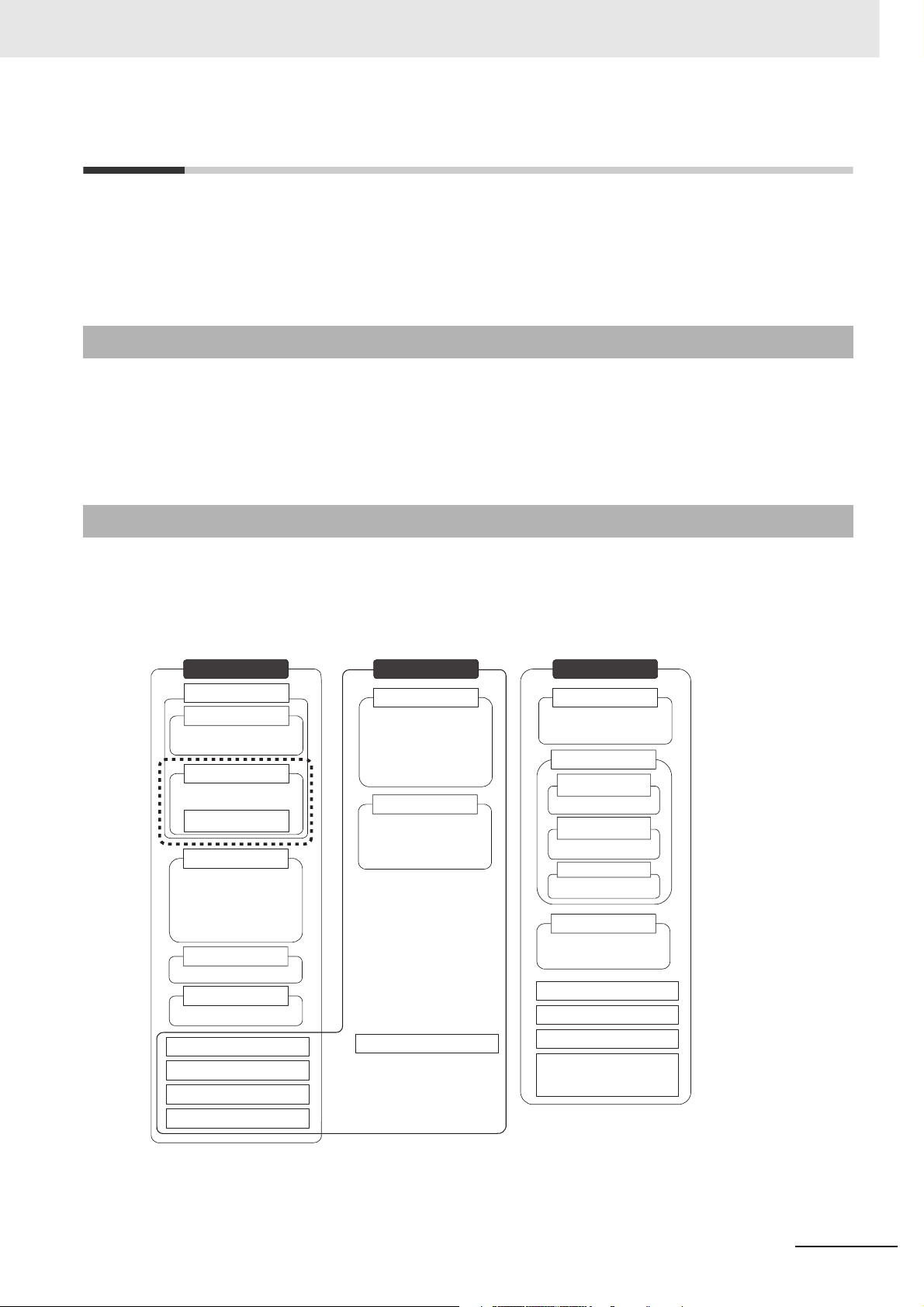
CJ2 CPU Unit Manuals
Information on the CJ2 CPU Units is provided in the following manuals. Refer to the appropriate manual
for the information that is required.
Mounting
and Setting
1
Hardware
2
Wiring
CJ-series CJ2 CPU Unit
Hardware User’s Manual
(Cat. No. W472)
• Unit part names and
specifications
• Basic system
configuration
• Unit mounting
procedure
• Setting procedure for
DIP switch and rotary
switches on the front of
the CPU Unit
For details on built-in
EtherNet/IP port, refer to
the EtherNet/IP Unit
Operation Manual (W465)
CJ-series CJ2 CPU Unit
Software User’s Manual
(Cat. No. W473)
CS/CJ/NSJ Series
Instructions Reference
Manual (Cat. No. W474)
This Manual
CJ2M CPU Unit Pulse
I/O Module User's
Manual (Cat. No. W486)
•
Specifications and wiring
of Pulse I/O Modules
•
Available pulse I/O
functions and allocations
Connecting
Online to
3
the PLC
Software
4
Setup
Creating the
5
Program
Checking
and
Debugging
6
Operation
• Wiring the Power
Supply Unit
• Wiring Basic I/O Units
and external I/O
devices
CX-Programmer Support
Software Connecting
Cables
Procedures for connecting
the CX-Programmer
Support Software
Software setting methods for the
CPU Unit (including I/O memory
allocation, PLC Setup settings,
Special I/O Unit parameters,
CPU Bus Unit parameters, and
routing tables.)
For details on built-in EtherNet/IP
port, refer to the EtherNet/IP Unit
Operation Manual (W465).
• Program types and basic
information
• CPU Unit operation
• Internal memory
• Data management using
file memory in the CPU
Unit
• Built-in CPU functions
• Settings
Detailed information
on programming
instructions
•
Wiring methods between
Pulse I/O Modules and
external I/O devices
Software setting
procedures for Pulse
I/O Modules (I/O
memory allocations
and PLC Setup
settings)
Pulse I/O functions
Maintenance
and
7
Troubleshooting
2
• Checking I/O wiring, setting the
Auxiliary Area settings, and
performing trial operation
• Monitoring and debugging with
the CX-Programmer
Error codes and
remedies if a problem
occurs
CJ2M CPU Unit Pulse I/O Module User’s Manual

Manual Configuration
The CJ2 CPU manuals are organized in the sections listed in the following tables. Refer to the appropriate section in the manuals as required.
Hardware User’s Manual (Cat. No. W472)
Section Content
Section 1 Overview
Section 2 Basic System Configuration and Devices
Section 3 Nomenclature and
Functions
Section 4 Support Software
Section 5 Installation
Section 6 Troubleshooting
Section 7 Inspection and Maintenance
Section 8 Backup Operations This section describes the procedure to back up PLC data.
Appendices
This section gives an overview of the CJ2 CPU Units and describes the features and
specifications.
This section describes the system configuration for the CJ2 CPU Unit.
This section describes the part names and functions of the CPU Unit and Configuration
Units.
This section describes the types of Support Software to use to perform programming and
debugging and how to connect the PLC to the Support Software.
This section describes the installation locations and how to wire CPU Units and Configuration Units.
This section describes how to check the status for errors that occur during system operation and the remedies for those errors.
This section describes periodic inspection, the service life of the Battery and Power Supply Unit, and how to replace the Battery.
The appendices provide Unit dimensions, details on fatal and non-fatal errors, information on connecting to serial ports on the CPU Unit, the procedure for installing the USB
driver on a computer, and information on load short-circuit protection and line disconnection detection.
Software User’s Manual (Cat. No. W473)
Section Content
Section 1 Overview
Section 2 Internal Memory in the
CPU Unit
Section 3 CPU Unit Operation This section describes the internal operation of the CPU Unit.
Section 4 CPU Unit Initialization This section describes the initial setup of the CPU Unit.
Section 5 Understanding Programming
Section 6 I/O Memory Areas This section describes the I/O memory areas in the CPU Unit.
Section 7 File Operations
Section 8 I/O Allocations and
Unit Settings
Section 9 PLC Setup
Section 10 CPU Unit Functions This section describes functions that are built into the CPU Unit.
Section 11 Programming Devices
and Communications
Section 12 CPU Unit Cycle Time This section describes how to monitor and calculate the cycle time.
Appendices
This section gives an overview of the CJ2 CPU Units and describes the features and
specifications.
This section describes the types of memory in the CPU Unit and the data that is stored.
This section describes program types and programming details, such as symbols and
programming instructions.
This section describes the files that can be stored in the CPU Unit, the storage destination for those files, and file operations.
This section describes the I/O allocations used to exchange data between the CPU Unit
and other Units.
This section describes details on the PLC Setup settings, which are used to perform
basic settings for the CPU Unit.
This section describes the procedure for connecting the CJ2 CPU Unit to the CX-Programmer or other Support Software and to other devices.
The appendices provide information on programming instructions, execution times, number of steps, Auxiliary Area words and bits, a memory map of the continuous PLC memory addresses, I/O memory operation when power is interrupted, and a comparison of
CJ-series and CS-series PLCs.
CJ2M CPU Unit Pulse I/O Module User’s Manual
3

Instructions Reference Manual (Cat. No. W474)
Section Content
Section 1 Basic Understanding
of Instructions
Section 2 Summary of Instructions
Section 3 Instructions
Section 4 Instruction Execution
Times and Number of Steps
Appendices
This section provides basic information on designing ladder programs for a CS/CJ/NSJseries CPU Unit.
This section provides a summary of instructions used with a CS/CJ/NSJ-series CPU
Unit.
This section describes the functions, operands and sample programs of the instructions
that are supported by a CS/CJ/NSJ-series CPU Unit.
This section provides the instruction execution times for each CS/CJ/NSJ-series CPU
Unit instruction.
The appendices provide a list of instructions by function code and by mnemonic and an
ASCII table for the CS/CJ/NSJ-series CPU Units.
Pulse I/O Module User's Manual (Cat. No. W486) (This Manual)
Section Content
Section 1 Overview This section gives an overview of the Pulse I/O Module and describes its features.
Section 2 I/O Application Procedures and Function Allocations
Section 3 I/O Specifications and
Wiring for Pulse I/O Modules
Section 4 Normal I/O This section describes the normal I/O.
Section 5 Quick-response Inputs
Section 6 Interrupts This section describes the interrupt input function.
Section 7 High-speed Counters This section describes the high-speed counter inputs and high-speed counter interrupts.
Section 8 Pulse Outputs
Section 9 PWM Outputs This section describes the variable-duty-factor pulse (PWM) outputs.
Appendices
This section lists the pulse functions of the CJ2M CPU Units and describes the overall
application flow and the allocation of the functions.
This section provides the specifications and describes the wiring of the Pulse I/O Module.
This section describes the quick-response function that can be used to input signals that
are shorter than the cycle time.
This section describes positioning functions, such as trapezoidal control, S-curve control,
jogging, and origin search functions.
The appendices provide a table of flag changes for pulse outputs, a comparison table
with other models, and a performance table.
4
CJ2M CPU Unit Pulse I/O Module User’s Manual
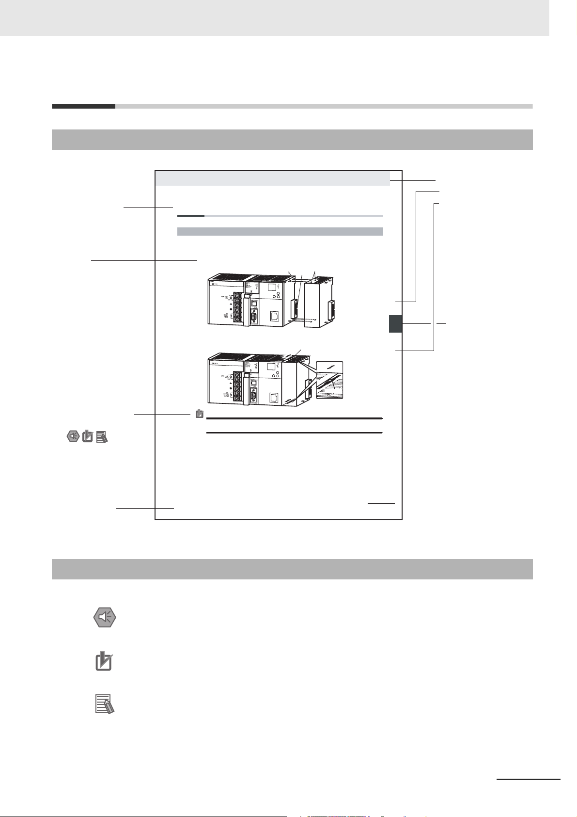
Manual Structure
Page Structure
The following page structure is used in this manual.
Level 2 heading
Level 3 heading
A step
in a procedure
Special Information
(See below.)
5-2 Installation
5-2-1 Connecting PLC Components
The Units that make up a CJ-series PLC can be connected simply by pressing the Units together and
locking the sliders by moving them toward the back of the Units. The End Cover is connected in the
same way to the Unit on the far right side of the PLC.
1. Join the Units so that the connectors fit exactly.
2. The yellow sliders at the top and bottom of each Unit lock the Units together. Move the sliders
toward the back of the Units as shown below until they click into place.
Precautions for Correct UsePrecautions for Correct Use
If the locking tabs are not secured properly, the connectors may become loose and not function
properly. Be sure to slide the locking tabs until they are securely in place.
Hook
Connector
Move the sliders toward the back
until they lock into place.
Hook holes
Release
Lock
Slider
5 Installation
Level 1 heading
Level 2 heading
Level 3 heading
Gives the current
headings.
noitallatsnI 2-5
5
Page tab
Gives the number
of the section.
gnitcennoC 1-2-5
P
opmoC CL
stnen
Manual name
CJ2 CPU Unit Hardware User’s Manual
This illustration is provided only as a sample and may not literally appear in this manual.
Special Information
Special information in this manual is classified as follows:
Precautions for Safe Use
Precautions on what to do and what not to do to ensure using the product safely.
Precautions for Correct Use
Precautions on what to do and what not to do to ensure proper operation and performance.
Additional Information
Additional information to increase understanding or make operation easier.
5-13
CJ2M CPU Unit Pulse I/O Module User’s Manual
5

6
CJ2M CPU Unit Pulse I/O Module User’s Manual

Sections in this Manual
1
2
1
2
3
4
5
6
Overview
I/O Application Procedures and Function Allocations
I/O Specifications and Wiring for Pulse I/O Modules
Normal I/O
Quick-response Inputs
Interrupts
3
4
5
6
7
8
7
8
9
A
9
High-speed Counters
A
Pulse Outputs
PWM Outputs
Appendices
CJ2M CPU Unit Pulse I/O Module User’s Manual
7

8
CJ2M CPU Unit Pulse I/O Module User’s Manual

CONTENTS
Introduction............................................................................................................... 1
CJ2 CPU Unit Manuals ............................................................................................. 2
Manual Structure ...................................................................................................... 5
Sections in this Manual............................................................................................ 7
Safety Precautions ................................................................................................. 17
Application Precautions......................................................................................... 21
Operating Environment Precautions .................................................................... 26
Regulations and Standards ................................................................................... 27
Unit Versions of CJ2 CPU Units ............................................................................ 30
Related Manuals ..................................................................................................... 31
Section 1 Overview
1-1 Pulse I/O Modules.................................................................................................................... 1-2
1-2 Overview of the Functions of CJ2M Pulse I/O ...................................................................... 1-4
1-3 Functions of CJ2M Pulse I/O ..................................................................................................1-6
Section 2 I/O Application Procedures and Function Allocations
2-1 Pulse I/O Module Application Procedure .............................................................................. 2-2
2-2 Allocating I/O Functions ......................................................................................................... 2-4
2-2-1 Specifying the Functions to Use ................................................................................................. 2-4
2-2-2 Selecting Functions in the PLC Setup ........................................................................................ 2-4
2-2-3 Allocating Functions to Input Terminals ...................................................................................... 2-5
2-2-4 Allocating Functions to Output Terminals ...................................................................................2-7
2-3 PLC Setup ................................................................................................................................ 2-8
2-3-1 Normal Input Operation Setting .................................................................................................. 2-9
2-3-2 Interrupt Input and Quick-response Input Detailed Settings ...................................................... 2-9
2-3-3 High-speed Counter Settings.................................................................................................... 2-10
2-3-4 Pulse Output and Origin Search Settings ................................................................................. 2-11
Section 3 I/O Specifications and Wiring for Pulse I/O Modules
3-1 I/O Specifications .................................................................................................................... 3-2
3-1-1 Input Specifications..................................................................................................................... 3-2
3-1-2 Output Specifications for Sinking Transistor Outputs.................................................................. 3-4
3-1-3 Output Specifications for Sourcing Transistor Outputs ............................................................... 3-5
3-2 Wiring ....................................................................................................................................... 3-7
3-2-1 Connector Pin Allocations........................................................................................................... 3-7
3-2-2 I/O Circuit Configurations............................................................................................................ 3-8
3-2-3 Wiring ......................................................................................................................................... 3-8
CJ2M CPU Unit Pulse I/O Module User’s Manual
9

Section 4 Normal I/O
4-1 Normal Inputs .......................................................................................................................... 4-2
4-1-1 Overview .....................................................................................................................................4-2
4-1-2 Application Procedure ................................................................................................................. 4-2
4-2 Normal Outputs ....................................................................................................................... 4-5
4-2-1 Overview .....................................................................................................................................4-5
4-2-2 Flow of Operation........................................................................................................................ 4-5
4-3 Wiring ....................................................................................................................................... 4-7
4-3-1 Connector Pin Assignments........................................................................................................4-7
4-3-2 Wiring Examples .........................................................................................................................4-9
Section 5 Quick-response Inputs
5-1 Overview................................................................................................................................... 5-2
5-2 Application Procedure ............................................................................................................ 5-3
5-2-1 PLC Setup...................................................................................................................................5-3
5-2-2 Applicable Input Terminals .......................................................................................................... 5-5
5-3 Wiring ....................................................................................................................................... 5-6
5-3-1 Connector Pin Assignments........................................................................................................5-6
5-4 Creating Ladder Programs .....................................................................................................5-7
Section 6 Interrupts
6-1 Types of Interrupts .................................................................................................................. 6-2
6-1-1 Overview .....................................................................................................................................6-2
6-2 Interrupt Inputs ........................................................................................................................ 6-3
6-2-1 Overview .....................................................................................................................................6-3
6-2-2 Application Procedure ................................................................................................................. 6-5
6-2-3 Specifications..............................................................................................................................6-5
6-2-4 PLC Setup...................................................................................................................................6-6
6-2-5 Wiring........................................................................................................................................6-10
6-2-6 Creating Ladder Programs........................................................................................................ 6-10
6-2-7 Application Example..................................................................................................................6-14
Section 7 High-speed Counters
7-1 Overview................................................................................................................................... 7-2
7-1-1 Overview .....................................................................................................................................7-2
7-1-2 Application Procedure ................................................................................................................. 7-3
7-1-3 Specifications..............................................................................................................................7-3
7-1-4 PLC Setup...................................................................................................................................7-4
7-1-5 Wiring..........................................................................................................................................7-7
7-1-6 Creating Ladder Programs........................................................................................................ 7-12
7-2 High-speed Counter Inputs................................................................................................... 7-13
7-2-1 Pulse Input Methods Settings ................................................................................................... 7-13
7-2-2 Counting Mode Settings............................................................................................................7-14
7-2-3 Reset Methods.......................................................................................................................... 7-16
7-2-4 Reading the Present Value .......................................................................................................7-16
7-2-5 Frequency Measurement ..........................................................................................................7-17
7-2-6 Measuring the Rotational Speed or Total Rotations .................................................................. 7-18
7-2-7 Reading the Count Direction.....................................................................................................7-19
7-2-8 Temporarily Stopping Input Signal Counting (Gate Function) ...................................................7-20
10
CJ2M CPU Unit Pulse I/O Module User’s Manual

7-3 High-speed Counter Interrupts ............................................................................................ 7-21
7-3-1 Overview................................................................................................................................... 7-21
7-3-2 Present Value Comparison ....................................................................................................... 7-25
7-3-3 High-speed Counter Interrupt Instructions................................................................................ 7-28
7-4 Related Auxiliary Area Words and Bits ............................................................................... 7-35
7-5 Application Examples .......................................................................................................... 7-43
Section 8 Pulse Outputs
8-1 Overview................................................................................................................................... 8-3
8-1-1 Overview..................................................................................................................................... 8-3
8-1-2 Application Procedure................................................................................................................. 8-4
8-1-3 Specifications.............................................................................................................................. 8-5
8-1-4 Wiring ....................................................................................................................................... 8-11
8-2 Position Control..................................................................................................................... 8-27
8-2-1 Position Control Configuration .................................................................................................. 8-27
8-2-2 Relative Positioning and Absolute Positioning .......................................................................... 8-28
8-2-3 Application Example ................................................................................................................. 8-30
8-3 Jogging................................................................................................................................... 8-32
8-3-1 High-speed Jogging.................................................................................................................. 8-32
8-3-2 Low-speed Jogging................................................................................................................... 8-32
8-3-3 Application Example ................................................................................................................. 8-33
8-4 Implementing Interrupt Feeding........................................................................................... 8-35
8-4-1 Using the IFEED(892) (INTERRUPT FEEDING) Instruction .................................................... 8-35
8-4-2 Setting Procedure..................................................................................................................... 8-35
8-4-3 PLC Setup ................................................................................................................................ 8-36
8-4-4 INTERRUPT FEEDING Instruction: IFEED(892)...................................................................... 8-37
8-5 Defining the Origin ................................................................................................................ 8-39
8-5-1 Origin Searches........................................................................................................................ 8-39
8-5-2 Setting Procedure..................................................................................................................... 8-40
8-5-3 PLC Setup ................................................................................................................................ 8-40
8-5-4 Origin Search Instructions ........................................................................................................ 8-45
8-5-5 Origin Search Operations ......................................................................................................... 8-46
8-5-6 Origin Return ............................................................................................................................ 8-51
8-5-7 Changing the PV of the Pulse Output....................................................................................... 8-52
8-5-8 Application Example ................................................................................................................. 8-52
8-6 Reading the Pulse Output Present Value ............................................................................ 8-56
8-7 Reading the Pulse Output Frequency ................................................................................. 8-57
8-8 Related Auxiliary Area Bits................................................................................................... 8-58
8-9 Application Example ............................................................................................................. 8-63
8-9-1 Cutting Long Material Using Fixed Feeding.............................................................................. 8-63
8-9-2 Palletize: Two-axis Multipoint Positioning.................................................................................. 8-66
8-9-3 Vertically Conveying PCBs (Multiple Progressive Positioning) ................................................. 8-74
8-9-4 Feeding Wrapping Material: Interrupt Feeding ......................................................................... 8-80
8-10 Precautions when Using Pulse Outputs ............................................................................. 8-82
8-11 Pulse Output Patterns ........................................................................................................... 8-87
8-11-1 Speed Control (Continuous Mode) ...........................................................................................8-87
8-11-2 Positioning Control (Independent Mode) .................................................................................. 8-89
CJ2M CPU Unit Pulse I/O Module User’s Manual
11

Section 9 PWM Outputs
9-1 PWM Outputs (Variable Duty Ratio Pulse Outputs).............................................................. 9-2
9-1-1 Overview .....................................................................................................................................9-2
9-1-2 Application Procedure ................................................................................................................. 9-3
9-1-3 Wiring..........................................................................................................................................9-4
9-1-4 Ladder Program Example ...........................................................................................................9-5
Appendices
A-1 Flag Operations during Pulse Output....................................................................................A-2
A-2 Combinations of Pulse Control Instructions .......................................................................A-3
A-3 Comparison to CJ1M Built-in I/O Functions .........................................................................A-7
A-4 Performance Information ......................................................................................................A-10
A-4-1 Interrupt Input Response Time .................................................................................................A-10
A-4-2 Pulse Output Start Time............................................................................................................A-11
A-4-3 Response Times of Pulse Output Changes ..............................................................................A-11
Index................................................................................................................ Index-1
Revision History........................................................................................Revision-1
12
CJ2M CPU Unit Pulse I/O Module User’s Manual

Read and Understand this Manual
Please read and understand this manual before using the product. Please consult your OMRON representative
if you have any questions or comments.
Warranty and Limitations of Liability
WARRANTY
OMRON's exclusive warranty is that the products are free from defects in materials and workmanship for a
period of one year (or other period if specified) from date of sale by OMRON.
OMRON MAKES NO WARRANTY OR REPRESENTATION, EXPRESS OR IMPLIED, REGARDING NONINFRINGEMENT, MERCHANTABILITY, OR FITNESS FOR PARTICULAR PURPOSE OF THE
PRODUCTS. ANY BUYER OR USER ACKNOWLEDGES THAT THE BUYER OR USER ALONE HAS
DETERMINED THAT THE PRODUCTS WILL SUITABLY MEET THE REQUIREMENTS OF THEIR
INTENDED USE. OMRON DISCLAIMS ALL OTHER WARRANTIES, EXPRESS OR IMPLIED.
LIMITATIONS OF LIABILITY
OMRON SHALL NOT BE RESPONSIBLE FOR SPECIAL, INDIRECT, OR CONSEQUENTIAL DAMAGES,
LOSS OF PROFITS OR COMMERCIAL LOSS IN ANY WAY CONNECTED WITH THE PRODUCTS,
WHETHER SUCH CLAIM IS BASED ON CONTRACT, WARRANTY, NEGLIGENCE, OR STRICT
LIABILITY.
In no event shall the responsibility of OMRON for any act exceed the individual price of the product on which
liability is asserted.
IN NO EVENT SHALL OMRON BE RESPONSIBLE FOR WARRANTY, REPAIR, OR OTHER CLAIMS
REGARDING THE PRODUCTS UNLESS OMRON'S ANALYSIS CONFIRMS THAT THE PRODUCTS
WERE PROPERLY HANDLED, STORED, INSTALLED, AND MAINTAINED AND NOT SUBJECT TO
CONTAMINATION, ABUSE, MISUSE, OR INAPPROPRIATE MODIFICATION OR REPAIR.
CJ2M CPU Unit Pulse I/O Module User’s Manual
13

Application Considerations
SUITABILITY FOR USE
OMRON shall not be responsible for conformity with any standards, codes, or regulations that apply to the
combination of products in the customer's application or use of the products.
At the customer's request, OMRON will provide applicable third party certification documents identifying
ratings and limitations of use that apply to the products. This information by itself is not sufficient for a
complete determination of the suitability of the products in combination with the end product, machine,
system, or other application or use.
The following are some examples of applications for which particular attention must be given. This is not
intended to be an exhaustive list of all possible uses of the products, nor is it intended to imply that the uses
listed may be suitable for the products:
• Outdoor use, uses involving potential chemical contamination or electrical interference, or conditions or
uses not described in this manual.
• Nuclear energy control systems, combustion systems, railroad systems, aviation systems, medical
equipment, amusement machines, vehicles, safety equipment, and installations subject to separate
industry or government regulations.
• Systems, machines, and equipment that could present a risk to life or property.
Please know and observe all prohibitions of use applicable to the products.
NEVER USE THE PRODUCTS FOR AN APPLICATION INVOLVING SERIOUS RISK TO LIFE OR
PROPERTY WITHOUT ENSURING THAT THE SYSTEM AS A WHOLE HAS BEEN DESIGNED TO
ADDRESS THE RISKS, AND THAT THE OMRON PRODUCTS ARE PROPERLY RATED AND
INSTALLED FOR THE INTENDED USE WITHIN THE OVERALL EQUIPMENT OR SYSTEM.
PROGRAMMABLE PRODUCTS
OMRON shall not be responsible for the user's programming of a programmable product, or any
consequence thereof.
14
CJ2M CPU Unit Pulse I/O Module User’s Manual

Disclaimers
CHANGE IN SPECIFICATIONS
Product specifications and accessories may be changed at any time based on improvements and other
reasons.
It is our practice to change model numbers when published ratings or features are changed, or when
significant construction changes are made. However, some specifications of the products may be changed
without any notice. When in doubt, special model numbers may be assigned to fix or establish key
specifications for your application on your request. Please consult with your OMRON representative at any
time to confirm actual specifications of purchased products.
DIMENSIONS AND WEIGHTS
Dimensions and weights are nominal and are not to be used for manufacturing purposes, even when
tolerances are shown.
PERFORMANCE DATA
Performance data given in this manual is provided as a guide for the user in determining suitability and does
not constitute a warranty. It may represent the result of OMRON's test conditions, and the users must
correlate it to actual application requirements. Actual performance is subject to the OMRON Warranty and
Limitations of Liability.
ERRORS AND OMISSIONS
The information in this manual has been carefully checked and is believed to be accurate; however, no
responsibility is assumed for clerical, typographical, or proofreading errors, or omissions.
CJ2M CPU Unit Pulse I/O Module User’s Manual
15

16
CJ2M CPU Unit Pulse I/O Module User’s Manual
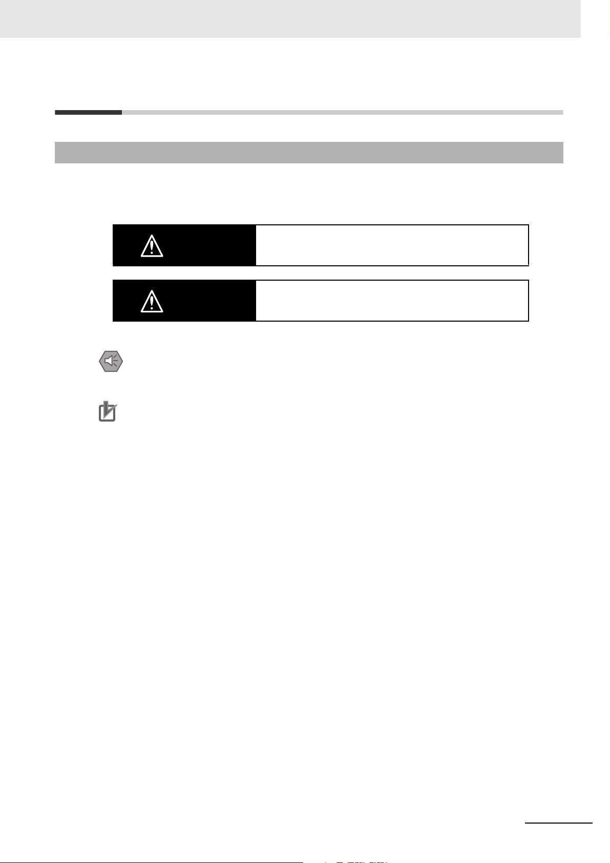
Safety Precautions
Definition of Precautionary Information
The following notation is used in this manual to provide precautions required to ensure safe usage of a
CJ-series PLC. The safety precautions that are provided are extremely important to safety. Always read
and heed the information provided in all safety precautions.
WARNING
Caution
Precautions for Safe Use
Indicates precautions on what to do and what not to do to ensure using the product safely.
Precautions for Correct Use
Indicates precautions on what to do and what not to do to ensure proper operation and performance.
Indicates a potentially hazardous situation which, if not avoided,
could result in death or serious injury. Additionally, there may be
severe property damage.
Indicates a potentially hazardous situation which, if not avoided,
may result in minor or moderate injury, or property damage.
CJ2M CPU Unit Pulse I/O Module User’s Manual
17

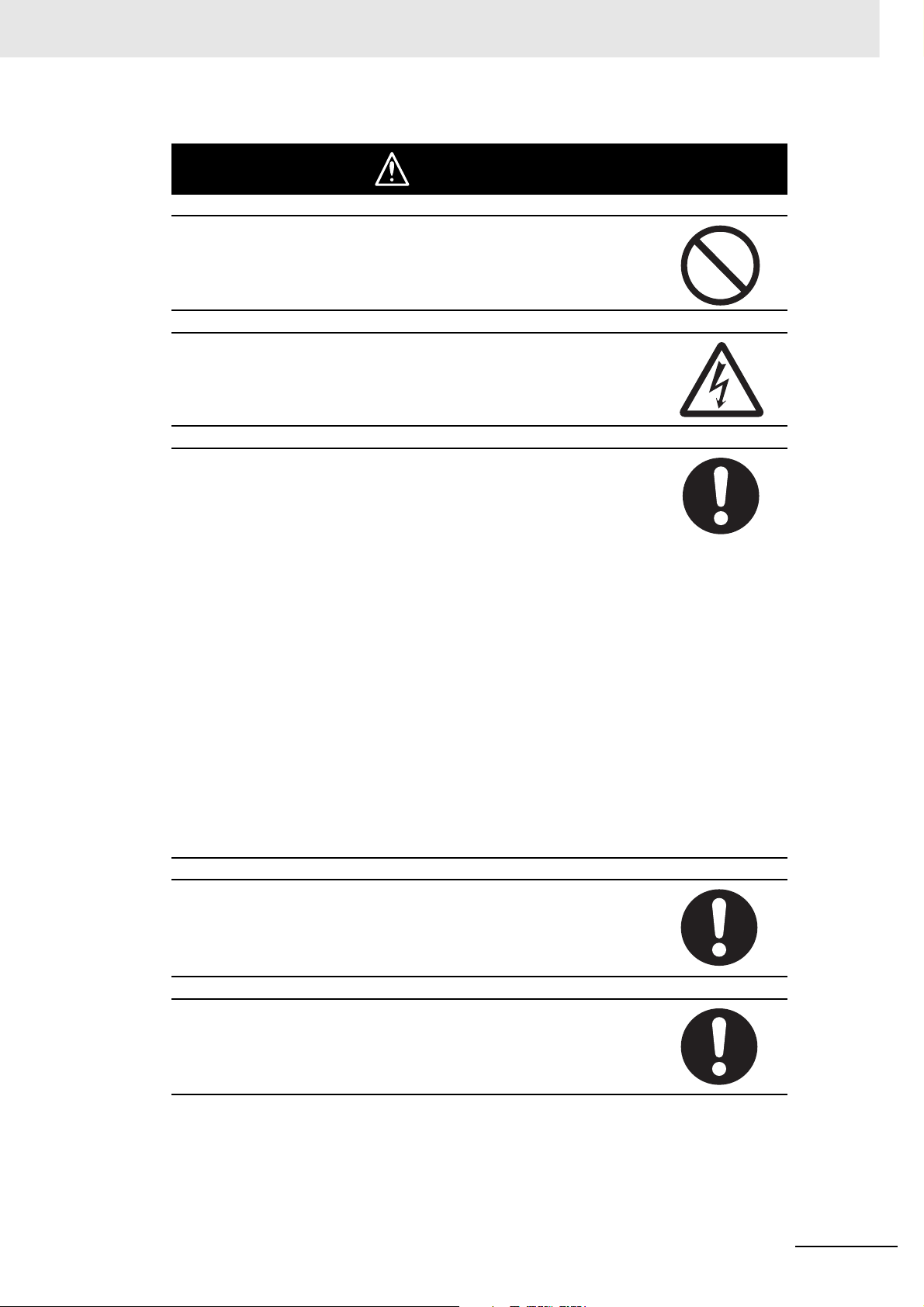
Symbols
The triangle symbol indicates precautions (including warnings).
The specific operation is shown in the triangle and explained in
text. This example indicates a precaution for electric shock.
The circle and slash symbol indicates operations that you must
not do. The specific operation is shown in the circle and
explained in text.
The filled circle symbol indicates operations that you must do.
The specific operation is shown in the circle and explained in
text. This example shows a general precaution for something
that you must do.
The triangle symbol indicates precautions (including warnings).
The specific operation is shown in the triangle and explained in
text. This example indicates a general precaution.
The triangle symbol indicates precautions (including warnings).
The specific operation is shown in the triangle and explained in
text. This example indicates a precaution for hot surfaces.
18
CJ2M CPU Unit Pulse I/O Module User’s Manual
WARNING
Do not attempt to take any Unit apart or touch the inside of any Unit while the
power is being supplied. Doing so may result in electric shock.
Do not touch any of the terminals or terminal blocks while the power is being
supplied. Doing so may result in electric shock.
Provide safety measures in external circuits (i.e., not in the Programmable
Controller), including the following items, to ensure safety in the system if an
abnormality occurs due to malfunction of the Programmable Controller or
another external factor affecting the operation of the Programmable Controller. “Programmable Controller” indicates the CPU Unit and all other Units and
is abbreviated “PLC” in this manual. Not doing so may result in serious accidents.
• Emergency stop circuits, interlock circuits, limit circuits, and similar safety
measures must be provided in external control circuits.
• The PLC will turn OFF all outputs when its self-diagnosis function detects
any error or when a severe failure alarm (FALS) instruction is executed.
Unexpected operation, however, may still occur for errors in the I/O control
section, errors in I/O memory, and other errors that cannot be detected by
the self-diagnosis function. As a countermeasure for all such errors, external safety measures must be provided to ensure safety in the system.
• The PLC outputs may remain ON or OFF due to deposition or burning of
the output relays or destruction of the output transistors. As a countermeasure for such problems, external safety measures must be provided to
ensure safety in the system.
• Provide measures in the computer system and programming to ensure
safety in the overall system even if communications errors or malfunctions
occur in data link communications or remote I/O communications.
Confirm safety before transferring data files stored in the file memory (Memory Card or EM file memory) to the I/O area (CIO) of the CPU Unit using a
peripheral tool. Otherwise, the devices connected to the output unit may malfunction regardless of the operation mode of the CPU Unit.
Fail-safe measures must be taken by the customer to ensure safety in the
event of incorrect, missing, or abnormal signals caused by broken signal
lines, momentary power interruptions, or other causes. Serious accidents
may result from abnormal operation if proper measures are not provided.
CJ2M CPU Unit Pulse I/O Module User’s Manual
19
Caution
Execute online edit only after confirming that no adverse effects will be
caused by extending the cycle time. Otherwise, the input signals may not be
readable.
Confirm safety at the destination node before transferring a program, PLC
Setup, I/O tables, I/O memory contents, or parameters to another node or
changing contents of the any of these items. Transferring or changing data
can result in unexpected system operation.
The CJ2 CPU Units automatically back up the user program and parameter
data to flash memory when these are written to the CPU Unit. I/O memory
including the DM, EM, and Holding Areas), however, is not written to flash
memory.
The DM, EM, and Holding Areas can be held during power interruptions with
a battery. If there is a battery error, the contents of these areas may not be
accurate after a power interruption. If the contents of the DM, EM, and Holding Areas are used to control external outputs, prevent inappropriate outputs
from being made whenever the Battery Error Flag (A402.04) is ON.
Tighten the terminal screws on the AC Power Supply Unit to the torque specified in the operation manual. The loose screws may result in burning or malfunction.
Do not touch the Power Supply Unit when power is being supplied or immediately after the power supply is turned OFF. The Power Supply Unit will be hot
and you may be burned.
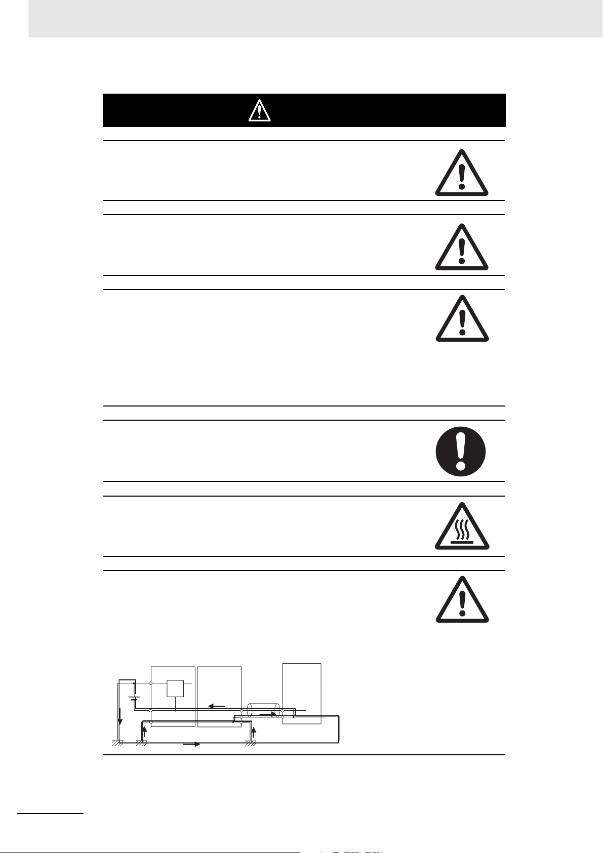
When connecting a personal computer or other peripheral device to a PLC to
which a non-insulated Power Supply Unit (CJ1W-PD022) is mounted, either
ground the 0 V side of the external power supply or do not ground the external power supply at all ground. A short-circuit will occur in the external power
supply if incorrect grounding methods are used. Never ground the 24 V side,
as shown below.
Wiring in Which the 24-V Power Supply Will Short
Non-insulated
DC power supply
24 V
Peripheral
0 V
cable
0 V
20
FG
Power Supply
Unit
CPU Unit
Peripheral device (e.g.,
personal computer)
CJ2M CPU Unit Pulse I/O Module User’s Manual

Application Precautions
Observe the following precautions when using a CJ-series PLC.
z Power Supply
• Always use the power supply voltages specified in the user’s manuals. An incorrect voltage may
result in malfunction or burning.
• Exceeding the capacity of the Power Supply Unit may prevent the CPU Unit or other Units from
starting.
• Take appropriate measures to ensure that the specified power with the rated voltage and frequency is supplied. Be particularly careful in places where the power supply is unstable. An incorrect power supply may result in malfunction.
• Always turn OFF the power supply to the PLC before attempting any of the following. Not turning
OFF the power supply may result in malfunction or electric shock.
• Mounting or dismounting Power Supply Units, I/O Units, CPU Units, Option Boards, Pulse I/O
Modules or any other Units.
• Assembling the Units.
• Setting DIP switches or rotary switches.
• Connecting cables or wiring the system.
• Connecting or disconnecting the connectors.
• When cross-wiring terminals, the total current for all the terminal will flow in the wire. Make sure
that the current capacity of the wire is sufficient.
• Observe the following precautions when using a Power Supply Unit that supports the Replacement Notification Function.
• Replace the Power Supply Unit within six months if the display on the front of the Power Supply Unit alternates between 0.0 and A02, or if the alarm output automatically turns OFF.
• Keep the alarm output cable separated from power line and high-voltage lines.
• Do not apply a voltage or connect a load exceeding the specifications to the alarm output.
• When storing the Power Supply Unit for more than three months, store it at −20 to 30°C and
25% to 70% humidity to preserve the Replacement Notification Function.
• If the Power Supply Unit is not installed properly, heat buildup may cause the replacement notification signal to appear at the wrong time or may cause interior elements to deteriorate or
become damaged. Use only the standard installation method.
• Do not touch the terminals on the Power Supply Unit immediately after turning OFF the power
supply. Residual voltage may cause electrical shock.
• Observe the following precautions to prevent failure due to difference in electrical potential if the
computer is connected to the PLC.
• Before connecting a laptop computer to the PLC, disconnect the power supply plug of the
computer from the AC outlet. Residual current in the AC adaptor may cause difference in electrical potential to occur between the computer and the PLC. After you connect the computer
and PLC, supply the power again from the AC adaptor.
• If the computer has an FG terminal, make the connections so that it has the same electrical
potential as the FG (GR) terminal on the PLC.
• If the computer is grounded to a separate location, difference in electrical potential may occur
depending on the grounding conditions.
z Installation
• Do not install the PLC near sources of strong high-frequency noise.
• Before touching a Unit, be sure to first touch a grounded metallic object in order to discharge any
static build-up. Not doing so may result in malfunction or damage.
CJ2M CPU Unit Pulse I/O Module User’s Manual
21

• Be sure that the terminal blocks, connectors, Memory Cards, Option Boards, Pulse I/O Modules,
expansion cables, and other items with locking devices are properly locked into place.
• The sliders on the tops and bottoms of the Power Supply Unit, CPU Unit, I/O Units, Special I/O
Units, CPU Bus Units, and Pulse I/O Modules must be completely locked (until they click into
place) after connecting to adjacent Units. It may not be possible to achieve proper functionality if
the sliders are not locked.
z Wiring
• Follow the instructions in this manual to correctly perform wiring.
• Double-check all wiring and switch settings before turning ON the power supply. Incorrect wiring
may result in burning.
• Be sure that all terminal screws, and cable connector screws are tightened to the torque specified
in the relevant manuals. Incorrect tightening torque may result in malfunction.
• Mount terminal blocks and connectors only after checking the mounting location carefully.
• Leave the label attached to the Unit when wiring. Removing the label may result in malfunction if
foreign matter enters the Unit.
• Remove the label after the completion of wiring to ensure proper heat dissipation. Leaving the
label attached may result in malfunction.
• Use crimp terminals for wiring. Do not connect bare stranded wires directly to terminals. Connection of bare stranded wires may result in burning.
• Do not apply voltages to the Input Units in excess of the rated input voltage. Excess voltages may
result in burning.
• Always connect to a ground of 100 Ω or less when installing the Units. Not connecting to a ground
of 100 Ω or less may result in electric shock.
A ground of 100 Ω or less must be installed when shorting the GR and LG terminals on the Power
Supply Unit.
• Do not apply voltages or connect loads to the Output Units in excess of the maximum switching
capacity. Excess voltage or loads may result in burning.
• Do not pull on the cables or bend the cables beyond their natural limit. Doing either of these may
break the cables.
• Do not place objects on top of the cables or other wiring lines. Doing so may break the cables.
• Do not use commercially available RS-232C personal computer cables. Always use the special
cables listed in this manual or make cables according to manual specifications. Using commercially available cables may damage the external devices or CPU Unit.
• Never connect pin 6 (5-V power supply) on the RS-232C port on the CPU Unit to any device other
than an NT-AL001 Link Adapter, CJ1W-CIF11 Converter, and Programmable Terminals (NV3WM@20L). The external device or the CPU Unit may be damaged.
22
z Handling
• The Power Supply Unit may possibly be damaged if the entire voltage for a dielectric strength test
is applied or shut OFF suddenly using a switch. Use a variable resistor to gradually increase and
decrease the voltage.
• Separate the line ground terminal (LG) from the functional ground terminal (GR) on the Power
Supply Unit before performing withstand voltage tests or insulation resistance tests. Not doing so
may result in burning.
• Make sure that the DIP switches and DM Area are set correctly before starting operation.
• After replacing the CPU Unit, a Special I/O Unit, or a CPU Bus Unit, make sure that the required
data for the DM Area, Holding Area, and other memory areas has been transferred to the new
Unit before restarting operation.
• Confirm that no adverse effect will occur in the system before attempting any of the following. Not
doing so may result in an unexpected operation.
• Changing the operation mode of the PLC (including the setting of the startup operation mode).
• Force-setting/force-resetting any bit in memory.
CJ2M CPU Unit Pulse I/O Module User’s Manual

• Changing the present value of any word or any set value in memory.
• Do not attempt to disassemble, repair, or modify any Units. Any attempt to do so may result in malfunction, fire, or electric shock.
• Do not drop the PLC or subject abnormal vibration or shock to it.
• The life of the battery will be reduced if the PLC is left for a period of time without a battery
installed and without power supply, and then a battery is installed without turning ON the power
supply.
• Replace the battery as soon as a battery error occurs or as soon as the specified battery backup
time expires. Be sure to install a replacement battery within two years of the production date
shown on the battery's label.
• Before replacing the battery, turn ON power for at least 5 minutes before starting the replacement
procedure and complete replacing the battery within 5 minutes of turning OFF the power supply.
Memory contents may be corrupted if this precaution is not obeyed.
• If the Battery Error Flag is used in programming the application, confirm system safety even if the
system detects a battery error before you replace the battery while the power is ON.
• Do not short the battery terminals or charge, disassemble, heat, or incinerate the battery. Do not
subject the battery to strong shocks. Doing any of these may result in leakage, rupture, heat generation, or ignition of the battery. Dispose of any battery that has been dropped on the floor or otherwise subjected to excessive shock. Batteries that have been subjected to shock may leak if they
are used.
• UL standards require that only an experienced engineer can replace the battery. Make sure that
an experienced engineer is in charge of battery replacement. Follow the procedure for battery
replacement given in this manual.
• Dispose of the product and batteries according to local ordinances as they apply.
• If the I/O Hold Bit is turned ON, the outputs from the PLC will not be turned OFF and will maintain
their previous status when the PLC is switched from RUN or MONITOR mode to PROGRAM
mode. Make sure that the external loads will not produce dangerous conditions when this occurs.
(When operation stops for a fatal error, including those produced with the FALS(007) instruction,
all outputs from Output Unit will be turned OFF and only the internal output status will be maintained.)
• Unexpected operation may result if inappropriate data link tables or parameters are set. Even if
appropriate data link tables and parameters have been set, confirm that the controlled system will
not be adversely affected before starting or stopping data links.
• Write programs so that any data that is received for data link communications is used only if there
are no errors in the CPU Units that are the sources of the data. Use the CPU Unit error information in the status flags to check for errors in the source CPU Units. If there are errors in source
CPU Units, they may send incorrect data.
• All CPU Bus Units will be restarted when routing tables are transferred from a Programming
Device to the CPU Unit. Restarting these Units is required to read and enable the new routing
tables. Confirm that the system will not be adversely affected before transferring the routing
tables.
• Tag data links will stop between related nodes while tag data link parameters are being transferred during PLC operation. Confirm that the system will not be adversely affected before transferring the tag data link parameters.
• If there is interference with network communications, output status will depend on the devices that
are being used. When using devices with outputs, confirm the operation that will occur when there
is interference with communications, and implement safety measures as required.
CJ2M CPU Unit Pulse I/O Module User’s Manual
23

• When creating an AUTOEXEC.IOM file from a Programming Device (a Programming Console or
the CX-Programmer) to automatically transfer data at startup, set the first write address to
D20000 and be sure that the size of data written does not exceed the size of the DM Area. When
the data file is read from the Memory Card at startup, data will be written in the CPU Unit starting
at D20000 even if another address was set when the AUTOEXEC.IOM file was created. Also, if
the DM Area is exceeded (which is possible when the CX-Programmer is used), the remaining
data will be written to the EM Area.
• The user program and parameter area data in the CJ2 CPU Units are backed up in the built-in
flash memory. The BKUP indicator will light on the front of the CPU Unit when the backup operation is in progress. Do not turn OFF the power supply to the CPU Unit when the BKUP indicator is
lit. The data will not be backed up if power is turned OFF.
• Check the user program and Unit parameter settings for proper execution before actually running
them on the Unit. Not checking the program and parameter settings may result in an unexpected
operation.
• When setting a Special I/O Unit or CPU Bus Unit in the I/O tables, carefully check the safety of the
devices at the connection target before restarting the Unit.
• Do not turn OFF the power supply to the PLC when reading or writing a Memory Card. Also, do
not remove the Memory Card when the BUSY indicator is lit. Doing so may make the Memory
Card unusable.
To remove a Memory Card, first press the memory card power supply switch and then wait for the
BUSY indicator to go out before removing the Memory Card.
• When restoring data, carefully check that the selected data is the correct data to be restored
before executing the restore operation. Depending on the contents of the selected data, the control system may operate unexpectedly after the data is restored.
• Some Special I/O Units and CPU Bus Units operate with parameters stored in the CPU Unit (e.g.,
words allocated in DM Area, data link tables, or Ethernet settings). Information on restrictions will
be displayed in the Information Area in the PLC Backup Tool if there are any restrictions for the
selected CPU Bus Unit or Special I/O Unit. Check the restrictions, and then be sure to select both
the CPU Unit and the CPU Bus Unit or Special I/O Unit when backing up or restoring data. The
control system may operate unexpectedly if the equipment is started with the data backed up or
restored without selecting both Units.
• Information on restrictions will be displayed in the Information Area in the PLC Backup Tool if the
data to be stored includes a Unit that has restrictions on backup. Check the information on restrictions and take the required countermeasures. The control system may operate unexpectedly
when the equipment is operated after the data is restored
• Before restoring data during PLC operation, be sure that there will be no problem if PLC operation
stops. If the PLC stops at an unexpected time, the control system may operate unexpectedly.
• Be sure to turn the PLC power supply OFF and then back ON after restoring data. If the power is
not reset, the system may not be updated with the restored data, and the control system may
operate unexpectedly.
• Data on forced status can be backed up but it cannot be restored. Perform the procedure to forceset or force-reset bits from the CX-Programmer as required before starting operation after restoring data that includes forced status. Depending on the difference in the forced status, the control
system may operate unexpectedly.
• If a symbol or memory address (only symbols are allowed for ST programming) is specified for the
suffix of an array variable in ladder or ST programming, be sure that the specified element number
does not exceed the maximum memory area range.
Specifying an element number that exceeds the maximum range of the memory area specified for
the symbol will result accessing data in a different memory area, and may result in unexpected
operation.
• If a symbol or address is specified for an offset in a ladder diagram, program so that the memory
area of the start address is not exceeded when the offset is specified indirectly using a word
address or symbol.
If an indirect specification causes the address to exceed the area of the start address, the system
will access data in other area, and unexpected operation may occur.
24
CJ2M CPU Unit Pulse I/O Module User’s Manual
 Loading...