

Page 1
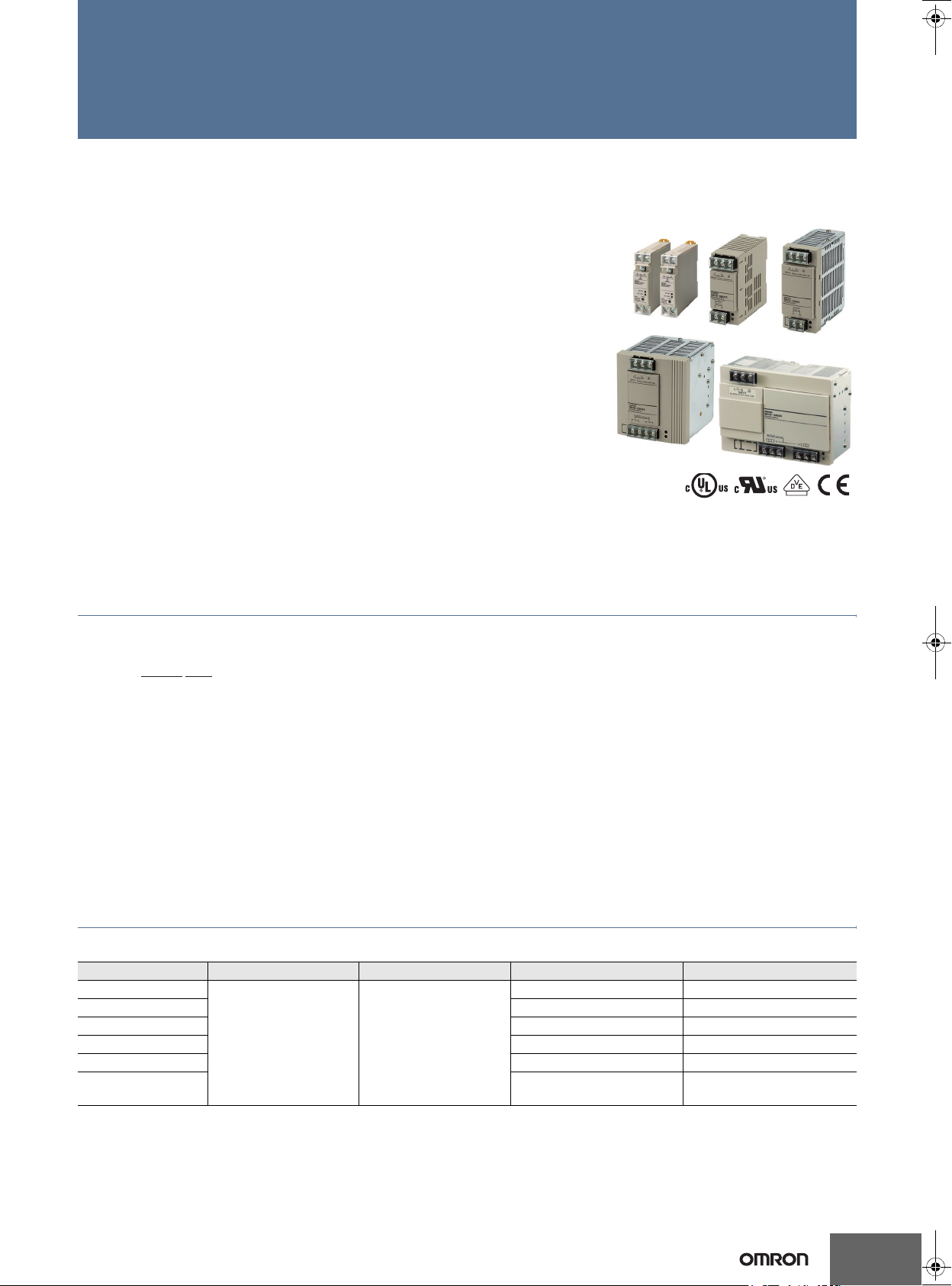
Switch Mode Power Supply
S8VS 15/30/60/120/240/480 W Models
Compact High capacity, Natural Cooling Power Supply Range from
0.65 A up to 20 A with Output Voltage of 24 VDC
• Only 6 models to cover all applications
• EMI Class B Compliant
• Output indicator LED green
• Mount to DIN Rail.
• Complies with SEMI F47-0200 (200 VAC input).
• RoHS-compliant.
• Safety standards:
UL508/60950-1,
CSA C22.2 No. 107.1/60950-1 (60 W to 480 W),
EN50178 (= VDE0160),
EN60950-1 (= VDE0805 Teil 1)
Note: Refer to Safety Precautions on page 11
Model Number Structure
Model Number Legend
S8VS- @@@@@
1 2
1. Power Ratings
015: 15 W
030: 30 W
060: 60 W
120: 120 W
240: 240 W
480: 480 W
2. Output voltage
24: 24 V
Ordering Information
List of Models
Power ratings Input voltage Output voltage Output current Model number
15 W
30 W 1.3 A S8VS-03024
60 W 2.5 A S8VS-06024
120 W 5 A S8VS-12024
240 W 10 A S8VS-24024
480 W
100 to 240 VAC 24 VDC
0.65 A S8VS-01524
20 A
Peak current 30 A (200 VAC)
S8VS-48024
1
Page 2
S8VS
Specifications
Ratings/Characteristics
Item Power ratings 15 W 30 W 60 W
Efficiency (typical) 77% min. 80% min. 78% min.
Voltage*1 100 to 240 VAC (85 to 264 VAC)
Frequency *1 50/60 Hz (47 to 450 Hz)
Current
Input
Output
Additional
functions
Other
*1) Do not use an inverter output for the Power Supply. Inverters with an output frequency of 50/60 Hz are available, but the rise in the internal temperature of the Power
Supply may result in ignition or burning.
*2) Refer to
*3) If the output voltage adjuster (V. ADJ) is turned, the voltage will increase by more than +15% of the voltage adjustment range. When adjusting the output voltage, confirm
the actual output voltage from the Power Supply and be sure that the load is not damaged.
Power factor ---
Harmonic current emissions Conforms to EN61000-3-2
Leakage
current
Inrush
current *2
Voltage adjustment range *3 −10% to 15% (with V.ADJ)
Ripple 2.0% (p-p) max. (at rated input/output voltage)
Input variation influence 0.5% max. (at 85 to 264 VAC input, 100% load)
Load variation influence
(rated input voltage)
Temperature variation influence 0.05%/°C max.
Startup time *2
Hold time *2 20 ms min. (at rated input/output voltage)
Overload protection *2
Overvoltage protection *2 Yes (a zener diode clamp) *4 Yes *5 Yes
Undervoltage alarm indication Yes (color: red) No
Parallel operation No
Series operation Yes for up to 2 Power Supplies (with external diode)
Operating ambient temperature Refer to the derating curve in
Storage temperature −25 to 65°C
Operating ambient humidity 25% to 85% (Storage humidity: 25% to 90%)
Dielectric strength
Insulation resistance 100 MΩ min. (between all outputs and all inputs/ PE terminals) at 500 VDC
Vibration resistance
Shock resistance
Output indicator Yes (color: green)
EMI
EMS Conforms to EN61204-3 high severity levels
Approved standards
SEMI F47-0200 (200 VAC input)
MTBF *7 > 500.000 hrs > 250.000 hrs
Weight 160 g max. 180 g max. 330 g max.
Engineering Data
on page 7 for details.
100 V input 0.45 A max. 0.9 A max. 1.7 A max.
200 V input 0.25 A max. 0.6 A max. 1.0 A max.
100 V input 0.5 mA max.
200 V input 1.0 mA max.
100 V input 25 A max. (for a cold start at 25°C)
200 V input 50 A max. (for a cold start at 25°C)
Conducted
Emissions
Radiated
Emissions
2.0% max. (5 V), 1.5% max. (12 V, 24 V),
(with rated input, 0 to 100% load)
100 ms max.
(at rated input/output voltage)
105% to 160% of rated load current,
voltage drop, automatic reset
3.0 kVAC for 1 min. (between all inputs and outputs; detection current: 20 mA)
2.0 kVAC for 1 min. (between all inputs and PE terminals; detection current: 20 mA)
1.0 kVAC for 1 min. (between all outputs and PE terminals; detection current: 20 mA)
500 VAC for 1 min. (between all outputs and alarm outputs; detection current: 20 mA) (only for 60 W)
10 to 55 Hz, 0.375-mm single amplitude for 2 h each in X, Y, and Z directions
10 to 150 Hz, 0.35-mm single amplitude (5 G max.) for 80 min each in X, Y, and Z directions (only for 60 W)
150 m/s2, 3 times each in ±X, ±Y, and ±Z directions
Conforms to EN61204-3 EN55011 Class B and based on FCC Class A
Conforms to EN61204-3 EN55011 Class B
UL: UL508 (Listing; Class 2: Per UL1310), UL60950-1, UL1604 (Class I/Division2)
cUL: CSA C22.2 No.14 (Class 2), No.60950-1, No.213 (Class I/Division2)
cUL: CSA C22.2 No.14 (Class 2), No.60950-1, No.213 (Class I/Division2)
EN/VDE: EN50178 (=VDE0160), EN60950-1 (SELV) (=VDE0805 Teil 1)
According to VDE0106/P100, IP20 (except terminal block)
1,000 ms max. (at rated input/output voltage)
105% to 160% of rated load current, voltage drop, intermittent operation,
automatic reset
Engineering Data
. (with no icing or condensation)
1.5% max. (with rated input, 0 to
100% load)
Conforms to EN61204-3 EN55011
Group 1 Class B and based on FCC Class A
Conforms to EN61204-3 EN55011
Group 1 Class B
UL for standard models: UL508 (Listing;
Class 2:Per UL1310), UL60950-1
cUL: CSA C22.2 No.107.1(Class 2:
Per CSA C22.2 No. 223)
cUR: CSA No.60950-1
EN/VDE: EN50178 (= VDE0160),
EN60950-1
(SELV) (= VDE0805 Teil 1)
According to VDE 0106/P100, IP20
(except terminal block)
2
Page 3
S8VS
Item Power ratings 120 W 240 W 480 W
Efficiency (typical) 80% min. 83% min.
Voltage *1 100 to 240 VAC (85 to 264 VAC)
Frequency *1 50/60 Hz (47 to 63 Hz)
Current
Input
Output
Additional
functions
Other
*4) The overvoltage protection of the S8VS-01524 uses a zener diode clamp. If the internal feedback circuit is destroyed by any chance, the load may be destroyed by the
clamped output voltage (approx. 140% to 190% of the rated output voltage).
*5) To reset the protection, turn OFF the input power for three minutes or longer and then turn it back ON.
*6) To ensure the emission rating, a ferrite ring core should be used in all cabling (SEIWA E04SR301334 or equivalent model).
*7) MTBF stands for mean Time Between Failures, which is calculated according to the probability of accidental device failures,
and indicates reliability of devices.
Power factor 0.95 min.
Harmonic current emissions Conforms to EN61000-3-2
Leakage current
Inrush current *2
Voltage adjustment range *3 −10% to 15% (with V.ADJ) (guaranteed)
Ripple 2.0% (p-p) max. (at rated input/output voltage)
Input variation influence 0.5% max. (at 85 to 264 VAC input, 100% load)
Load variation influence
(rated input voltage)
Temperature variation influence 0.05%/°C max.
Startup time *2 1,000 ms max. (at rated input/output voltage)
Hold time *2 20 ms min. (at rated input/output voltage)
Overload protection *2
Overvoltage protection *2 Yes
Parallel operation No
Series operation Yes for up to 2 Power Supplies (with external diode)
Operating ambient temperature Refer to the derating curve in
Storage temperature −25 to 65°C
Operating ambient humidity 25% to 85% (Storage humidity: 25% to 90%)
Dielectric strength
Insulation resistance 100 MΩ min. (between all outputs/ alarm outputs and all inputs/ PE terminals) at 500 VDC
Vibration resistance
Shock resistance
Output indicator Yes (color: green)
EMI
EMS Conforms to EN61204-3 high severity levels
Approved standards
SEMI F47-0200 (200 VAC input)
MTBF*7 >250.000 hrs
Weight 550 g max. 1,150 g max. 1,700 g max.
100 V input 1.9 A max. 3.8 A max. 7.4 A max.
200 V input 1.1 A max. 2.0 A max. 3.9 A max.
100 V input 0.5 mA max.
200 V input 1.0 mA max.
100 V input 25 A max. (for a cold start at 25°C)
200 V input 50 A max. (for a cold start at 25°C)
1.5% max. (with rated input, 0 to 100% load)
105% to 160% of rated load current,
Conducted
Emissions
Radiated
Emissions
voltage drop, intermittent, automatic
reset
3.0 kVAC for 1 min. (between all inputs and outputs/ alarm outputs; detection current: 20 mA)
2.0 kVAC for 1 min. (between all inputs and PE terminals; detection current: 20 mA)
1.0 kVAC for 1 min. (between all outputs/ alarm outputs and PE terminals; detection current: 240 W, 20 mA/ 480 W,
30 mA)
500 VAC for 1 min. (between all outputs and alarm outputs; detection current: 20 mA)
10 to 55 Hz, 0.375-mm single amplitude for 2 h each in X, Y, and Z directions
10 to 150 Hz, 0.35-mm single amplitude (5 G max.) for 80 min each in X, Y, and Z directions (only for 240 W)
10 to 150 Hz, 0.35-mm single amplitude (3 G max.) for 80 min each in X, Y, and Z directions (only for 480 W)
150 m/s2, 3 times each in ±X, ±Y, and ±Z directions
Conforms to EN61204-3 EN55011 Group 1 Class B and based
on FCC Class A
Conforms to EN61204-3 EN55011 Group 1 Class B
UL: UL508 (Listing), UL60950-1
cUL: CSA C22.2 No. 107.1
UL: UL508 (Listing), UL60950-1
cUR: CSA No. 60950-1
EN/VDE: EN50178 (= VDE0160), EN60950-1 (SELV) (= VDE0805 Teil 1)
According to VDE0106/P100, IP20 (except terminal block)
105% to 160% of rated load current, voltage drop, automatic reset
Engineering Data
. (with no icing or condensation)
Conforms to EN61204-3 EN55011
Class A and based on FCC Class A
Conforms to EN61204-3 EN55011
Class B *6
Conforms to EN61204-3 EN55011
Class A
Conforms to EN61204-3 EN55011
Class B *6
UL: UL508 (Listing), UL60950-1
cUL: CSA C22.2 No. 107.1
UL: UL508 (Listing), UL60950-1
cUR: CSA No. 60950-1
EN/VDE: EN50178 (= VDE0160),
EN60950-1 (SELV) (= VDE0805 Teil 1)
According to VDE0106/P100, IP20
(except terminal block)
3
Page 4
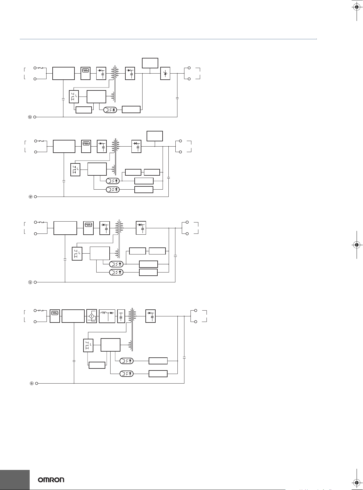
Connections
Block Diagrams
S8VS-01524 (15 W)
Fuse
2.5 A
AC (L)
INPUT
AC (N)
Noise filter
Inrush current
protection
circuit
Overcurrent
detection circuit
Rectifier/
smoothing
circuit
Drive control
circuit
Photocoupler
Rectifier/
smoothing
circuit
Voltage
detection circuit
Undervoltage
indicator
Overvoltage
protection
S8VS
+V
DC OUTPUT
−V
S8VS-03024 (30 W)
Fuse 3.15 A
AC (L)
INPUT
AC (N)
Noise filter
S8VS-06024 (60 W)
Fuse 3.15 A
AC (L)
INPUT
AC (N)
Noise filter
S8VS-12024 (120 W)
Fuse 3.5 A
AC (L)
INPUT
AC (N)
Inrush
current
protection
circuit
Noise filter
Inrush current
protection
circuit
Inrush current
protection
circuit
Rectification
Rectifier/
smoothing
circuit
Drive control
circuit
Rectifier/
smoothing
circuit
Drive control
circuit
Harmonic
current
suppression
Photocoupler
Photocoupler
Rectifier/smoothing circuit
Overcurrent
circuit
Rectifier/smoothing circuit
Overcurrent
circuit
Smoothing
Undervoltage
indicator
Current detection
circuit
Voltage
detection circuit
Overvoltage
detection circuit
Current detection
circuit
Volt age
detection circuit
Overvoltage
detection circuit
Rectifier/smoothing circuit
+V
DC OUTPUT
−V
+V
DC OUTPUT
−V
+V
DC OUTPUT
−V
4
Overcurrent
circuit
Drive control
circuit
Photocoupler
Volt age
detection circuit
Overvoltage
detection circuit
Page 5

S8VS-24024 (240 W)
S8VS
Fuse 7.5 A
AC (L)
INPUT
AC (N)
Noise filter
S8VS-48024 (480 W)
Fuse 12A
AC (L)
INPUT
AC (N)
Noise filter
Rectification
Inrush current
protection
circuit
Inrush
current
protection
circuit
Harmonic
current
suppression
Drive control
circuit
Rectification
Smoothing
Photocoupler
Harmonic
current
suppression
Rectifier/smoothing circuit
Overcurrent
circuit
Current
detection circuit
Volt age
detection circuit
Overvoltage
detection circuit
Smoothing
Auxiliary power
supply circuit
Drive circuit
Rectifier/
smoothing
circuit
+V
+V
−V
−V
Overvoltage
detection circuit
Control
circuit
Arithmetic
operation
circuit
DC OUTPUT
Rectifier/
smoothing circuit
Volt age
detection circuit
Current
detection circuit
Overcurrent
circuit
+V
+V
+V
DC OUTPUT
−V
−V
−V
5
Page 6

Construction and Nomenclature
Nomenclature
15 W, 30 W Models
1
No. Name Function
1 AC Input terminals (L), (N) Connect the input lines to these terminals. *1
2 Protective Earth terminal (PE) Connect the ground line to this terminal. *2
2
3 DC Output terminals (−V), (+V) Connect the load lines to these terminals.
S8VS-03024
Note: The S8VS-03024 is shown above.
60 W Models 120 W Models
S8VS-06024
1
4 Output indicator (DC ON: Green) Lights while a direct current (DC) output is ON.
4
5 Undervoltage indicator (DC LOW: Red) Lights when a drop is detected in the output voltage.
5
6 Output voltage adjuster (V.ADJ) Use to adjust the voltage.
6
*1) The fuse is located on the (L) side. It is NOT user-replaceable.
*2) This is the protective earth terminal specified in the safety standards. Always ground this terminal.
3
S8VS-12024
2
12
S8VS
S8VS-01524/S8VS-03024
240 W Models
S8VS-24024
12
3
480 W Models
S8VS-48024
1 2
4
5
4
5
3
3
4
5
No. Name Function
AC Input terminals
1
(L), (N)
Protective Earth termi-
2
nal (PE)
DC Output terminals
3
(−V), (+V)
Output indicator
4
(DC ON: Green)
Output voltage
5
adjuster (V.ADJ)
4
5
3
*1) The fuse is located on the (L) side. It is NOT user-replaceable.
*2) This is the protective earth terminal specified in the safety stan-
dards. Always ground this terminal.
Connect the input lines to these
terminals. *1
Connect the ground line to this
terminal. *2
Connect the load lines to these
terminals.
Lights while a direct current (DC)
output is ON.
Use to adjust the voltage.
6
Page 7

Engineering Data
S8VS
Derating Curve
S8VS-01524
120
100
Load ratio (%)
80
60
40
20
0
−20 −10 0 10 20 30 40 50 60 70 80
*1 Standard mounting
*2 Face-up mounting
*3 Horizontal mounting
Ambient temperature (°C)
S8VS-03024
120
100
Load ratio (%)
80
60
1
1
Mounting
Standard mounting with DIN rail
*1
*2
*3
*1
*2
Standard mounting with S82Y-VS30P
Note: The Side-mounting Bracket can be mounted from either side.
Horizontal mounting with S82Y-VS30P*
Face-up mounting with DIN rail
Face-up mounting with S82Y-VS30P
S82Y-VS30P
Side with label
40
20
0
−20 −10 0 10 20 30 40 50 60 70 80
*1 Standard mounting
*2 Face-up mounting/Horizontal mounting
Note: 1.
Internal parts may occasionally deteriorate or be damaged.
Ambient temperature (°C)
Do not use the Power Supply in areas outside the derating
curve (i.e., the area shown by shading
A
in the above graph).
2. If there is a derating problem, use forced air-cooling.
3. Provide a space of at least 20 mm when using standard
mounting and horizontal mounting. If 20 mm is not available,
make sure that the space is at least 10 mm. In this case,
reduce the corresponding derating curve by 5°C.
S8VS-06024/12024/24024/48024
120
100
Load (%)
80
60
40
20
1
See note 1.
Note: 1. Improper mounting will interfere with heat dissipation and
may occasionally result in deterioration or damage of
internal parts. Use the Product within the derating curve for
the mounting direction that is used. Do not use the Power
Supply mounted in any way not shown above.
2. Use a mounting bracket (S82Y-VS30P, sold separately)
when the Product is mounted horizontally.
3. Heat dissipation will be adversely affected. When the
Product is mounted facing horizontally, always place the
side with the label facing horizontally.
4. Use PFP-M End Plates on the top and bottom of the Power
Supply when mounting horizontally on a DIN rail.
Upper
Upper
Correct Incorrect
Standard mounting Face-up mounting
Note: Improper mounting will interfere with heat dissipation and may
occasionally result in deterioration or damage of internal parts.
Use the standard mounting method only.
0
−20 −10 0 10 20 30 40 50 60 70 80
Ambient temperature (°C)
Note: 1. Using side mounting bracket for right-side mounting
(excluding 240-W models).
2.
Internal parts may occasionally deteriorate or be damaged.
Do not use the Power Supply in areas outside the derating
curve (i.e., the area shown by shading
A
in the above graph).
3. If there is a derating problem, use forced air-cooling.
4. When using a 480 W model at an input voltage of 95 VAC or
less, derate the load by at least 80%.
7
Page 8

Overload Protection
The load and the power supply are automatically protected from
overcurrent damage by this function.
Overload protection is activated if the output current rises above
105% of the rated current.
When the output current returns within the rated range overload
protection is automatically cleared.
15-W Models 30-W Models
+30%
(approx.)
+15%
Output voltage (V)
Rated output
voltage
−10%
Variable range
Overvoltage protection
operating
S8VS
Output voltage (V)
0 100 50
60 W Models 120 W/240 W/480 W Models
Output voltage (V)
Intermittent operation
0 50 10 0 0 50 100
The values shown in the above diagrams are for reference only.
Output current (%)
Output current (%)
Output voltage (V)
0 100 50
Output voltage (V)
Intermittent
operation
Output current (%)
Output current (%)
Note: 1. Internal parts may occasionally deteriorate or be damaged
if a short-circuited or overcurrent state continues during
operation.
2. Internal parts may possibly deteriorate or be damaged if the
Power Supply is used for applications with frequent inrush
current or overloading at the load end. Do not use the Power
Supply for such applications.
Peak Output Current (S8VS-48024 only)
The peak current must satisfy the following conditions.
Input voltage range: 200 to 240 VAC
Peak current value: 30 A max.
Peak current pulse width: 2 s max.
Cycle: 60 s min.
Note: 1. Two seconds after the peak current is reached, the peak
current limiting function operates to stop the peak current
flow.
2. It takes 60 seconds for the peak current to be able to flow
again.
3. The peak current limiting function prevents the peak current
from flowing at 100 to 120 VAC.
Peak current limit
Peak current
condition
Overcurrent
protectionpoint
Output current
0 A
2 s
60 s min.
Overvoltage Protection
Consider the possibility of an overvoltage and design the system so
that the load will not be subjected to an excessive voltage even if the
feedback circuit in the Power Supply fails.
This power supply automatically protects itself and the load from
overvoltage.
When an excessive voltage that is approximately 130% of the rated
voltage or more is output, the output voltage is shut OFF.
Reset the input power by turning it OFF for at least three minutes and
then turning it back ON again.
0 V
The values shown in the above diagram is for reference only.
Note: 1. Do not turn ON the power again until the cause of the
overvoltage has been removed.
2. The overvoltage protection of the S8VS-01524 uses a zener
diode clamp. The output voltage will be clamped at approx.
140% or higher of the rated output voltage (approx. 140% to
190%). If the internal feedback circuit is destroyed by any
chance, the load may be destroyed by the clamped output
voltage (approx. 140% to 190% of the rated output voltage).
The power Supply will not restart if the output is turned OFF
by the overvoltage protection operation. If this occurs,
replace the Power Supply.
Undervoltage Alarm Indication
LED (DC LOW red) lights to warn of output voltage drop.
Detection voltage is set to approx. 80% (75 to 90%) of the rated
output voltage.
Note: This function monitors the voltage at the power supply output
terminals. To check actual voltage, measure voltage on the load
side.
Reference Values (15 W to 480 W Models)
Item Valu e Definition
MTBF stands for Mean Time
Between Failures, which is calculated according to the probability of
accidental device failures, and
indicates reliability of devices.
Therefore, it does not necessarily
Reliability
(MTBF)
15 W to 240 W:
135,000 hrs min.
480 W:
60,000 hrs min.
represent the life of the Product.
The life expectancy indicates
average operating hours under the
Life expectancy
10 yrs. min.
ambient temperature of 40°C and
a load rate of 50%. Normally this is
determined by the life expectancy
of the built-in aluminum electrolytic
capacitor.
Inrush Current, Startup Time, Output
Hold Time
AC input
voltage
AC input
current
Output
voltage
Input ON
Inrush current on input application
90%
Startup time (1,000 ms max.)
Input OFF
Hold time
(20 ms min.)
96.5%
8
Page 9

Dimensions
Note: All units are in millimeters unless otherwise indicated.
S8VS-01524 (15 W)
S8VS-03024 (30 W)
4.8
(Sliding: 10 max.)
S8VS
35.2
4
Note: The illustration is the S8VS-03024 model.
S8VS-06024 (60 W)
35.4
S8VS-12024 (120 W)
34.9
85
4.8
96.4
97
1
108.3
110.5
Rail stopper
Five, M4
with square washer
11.3
10.8
22.5
74
Rail stopper
Five, M4
with square washer
94
(Sliding: 10 max.)
10
95
40
4.5
(Sliding: 15 max.)
10
115
S8VS-24024 (240 W)
S8VS-48024 (480 W)
34.9
34.9
1
121.3
125.3
120.3
Screwless block (2.5-mm pitches)
Screwless block (2.5-mm pitches)
127.2
123.8
50
Rail stopper
Seven, M4
with square washer
94
Rail stopper
115
94
4.5
(Sliding: 15 max.)
100
115
10
50
Nine, M4 with square washer
4.5 (Sliding: 15 max.)
Rail stopper
150
115
Screwless block (2.5-mm pitches)
Rail stopper
10
70
4.5 (Sliding: 15 max.)
Rail stopper
9
Page 10

Mounting Brackets
Type Model Dimensions Appearance
Side-mounting Bracket
(For 15, 30 W models)
Side-mounting Bracket
(For 60, 120 W models)
S82Y-VS30P
S82Y-VS10S
85.4
S8VS
0.5
109.4
28
34
3.5
15
93.6
t = 0.8
±0.1
4.5 dia.
±0.1
80
35
64
t = 2.0
60
±0.1
55
13
7.1
±0.1
3.5 dia.
15
22.5
15
Left-side mounting Right-side mounting
Side-mounting Bracket
(For 240 W models)
S82Y-VS20S
Front-mounting Bracket
(For 60, 120, and 240 W
S82Y-VS10F
models) *1
*1) Two required to mount a 240 W model.
Note: Brackets cannot be used for 480 W models.
±0.1
4.5 dia.
80
60
114
t = 2.0
41
4.5 dia.±0.1
35
±0.1
35
40
50
±0.1
60
±0.1
13
55
78
25
7.3
10
Left-side mounting
*Right-side mounting also possible.
(For 60 W,
120 W types)
(For 240 W type)
*Use two S82Y-VS10F
brackets for the 240 W type.
10
Page 11

Safety Precautions
!CAUTION
Minor electric shock, fire, or Product failure may
occasionally occur. Do not disassemble, modify, or repair
the Product or touch the interior of the Product.
Minor burns may occasionally occur. Do not touch the
Product while power is being supplied or immediately
after power is turned OFF.
Fire may occasionally occur. Tighten terminal screws to
the specified torque (15 and 30 W models: 0.8 to 1.0 N·m/
60, 120, 240, and 480 W models: 1.08 N·m).
Minor injury due to electric shock may occasionally occur.
Do not touch the terminals while power is being supplied.
Always close the terminal cover after wiring.
Minor electric shock, fire, or Product failure may
occasionally occur. Do not allow any pieces of metal or
conductors or any clippings or cuttings resulting from
installation work to enter the Product.
Precautions for Safe Use
Mounting
Take adequate measures to ensure proper heat dissipation to
increase the long-term reliability of the Product. Be sure to allow
convection in the atmosphere around devices when mounting. Do
not use in locations where the ambient temperature exceeds the
range of the derating curve.
When cutting out holes for mounting, make sure that cuttings do not
enter the interior of the Products.
*1
*1. Convection of air
*2
*1
(15 W and 30 W Models)
Improper mounting will interfere with heat dissipation and may
occasionally result in deterioration or damage of internal parts. Use
the Product within the derating curve for the mounting direction that
is used.
Use a mounting bracket when the Product is mounted facing
horizontally.
Heat dissipation will be adversely affected. When the Product is
mounted facing horizontally, always place the side with the label
facing upward.
Always provide a space of 20 mm even when mounting horizontal or
facing horizontal. If a space of 20 mm is not available, reduce the
temperatures given in the derating curve on page 7 by 5°C and
provide a space of at least 10 mm.
(60 W, 120 W, 240 W, and 480 W Models)
Improper mounting will interfere with heat dissipation and may
occasionally result in deterioration or damage of internal parts. Use
the standard mounting method only.
The internal parts may occasionally deteriorate and be broken due to
adverse heat radiation. Do not loosen the screw on the side face of
the main body.
*2. 20 mm min.
S8VS
Wiring
Connect the ground completely. A protective earthing terminal
stipulated in safety standards is used. Electric shock or malfunction
may occur if the ground is not connected completely.
Minor fire may possibly occur. Ensure that input and output terminals
are wired correctly.
Do not apply more than 100 N force to the terminal block when
tightening it.
Be sure to remove the sheet covering the Product for machining
before power-ON so that it does not interfere with heat dissipation.
Use the following material for the wires to be connected to the S8VS
to prevent smoking or ignition caused by abnormal loads.
Recommended Wire Type
15 W and 30 W Models
Stranded wire Solid wire
AWG20 to 14
(0.5 to 2.0 mm
2
)
60 W, 120 W, 240 W, and 480 W Models
Model
S8VS-06024
S8VS-12024
S8VS-24024
S8VS-48024
Note: The rated current for output terminals is 10 A per terminal. Be
sure to use multiple terminals simultaneously for current that
exceeds the terminal rating.
AWG14 to 20
(Cross section 0.517 to 2.081 mm
AWG14 to 18
(Cross section 0.823 to 2.081 mm
Input terminals
AWG 14 to 16
(Cross section 1,309 to 2,081 mm
Output terminal
(see note 1.)
AWG 14
(Cross section 2,081 mm
Installation Environment
Do not use the Power Supply in locations subject to shocks or
vibrations. In particular, install the Power Supply as far away as
possible from contactors or other devices that are a vibration source.
Install the Power Supply well away from any sources of strong,
high-frequency noise and surge.
Operating Life
The life of a Power Supply is determined by the life of the electrolytic
capacitors used inside. Here, Arrhenius Law applies, i.e., the life will
be cut in half for each rise of 10°C or the life will be doubled for each
drop of 10°C. The life of the Power Supply can thus be increased by
reducing its internal temperature.
Ambient Operating and Storage Environments
Store the Power Supply at a temperature of −25 to 65°C and a
humidity of −25% to 90%.
Do not use the Power Supply in areas outside the derating curve
otherwise, internal parts may occasionally deteriorate or be
damaged.
Use the Power Supply at a humidity of 25% to 85%.
Do not use the Power Supply in locations subject to direct sunlight.
Do not use locations where liquids, foreign matter, or corrosive gases
may enter the interior of Products.
AWG20 to 16
(0.5 to 1.1 mm2)
Recommended wire size
For screw terminal
2
)
2
)
2
)
2
)
11
Page 12
S8VS
Overcurrent Protection
Internal parts may possibly deteriorate or be damaged if a
short-circuited or overcurrent state continues during operation.
Internal parts may possibly deteriorate or be damaged if the Power
Supply is used for applications with frequent inrush current or
overloading at the load end. Do not use the Power Supply for such
applications.
Dielectric Strength Test
If a high voltage is applied between an input and the case (FG), it will
pass though the LC of the built-in noise filter and energy will be
stored. If the high voltages used for dielectric strength testing are
turned ON and OFF with a switch, timer, or similar device, impulse
voltage will be generated when the voltage is turned OFF and
internal parts may possibly be damaged. To prevent the generation
of impulse voltages, reduce the applied voltage slowly with a variable
resistor on the test device or turn the voltage ON and OFF at the
zero-cross point.
Inrush Current
When two or more Power Supplies are connected to the same input,
the total current is the sum of the currents for each Supply. Select
fuses and circuit breakers giving sufficient consideration to the fusing
or operating characteristics so that fuses will not burn and breakers
will not break due to inrush current.
Output Voltage Adjuster (V.ADJ)
The output voltage adjuster (V.ADJ) may possibly be damaged if it is
turned with unnecessary force. Do not turn the adjuster with
excessive force.
After completing output voltage adjustment, be sure that the output
capacity or output current does not exceed the rated output capacity
or rated output current.
15 W, 30 W Models
If the output voltage is set to a value less than −10%, the
undervoltage alarm function may operate.
60 W, 120 W, 240 W, and 480 W Models
If the output voltage is set to a value less than 20 V (the factory
setting), the undervoltage alarm function may operate.
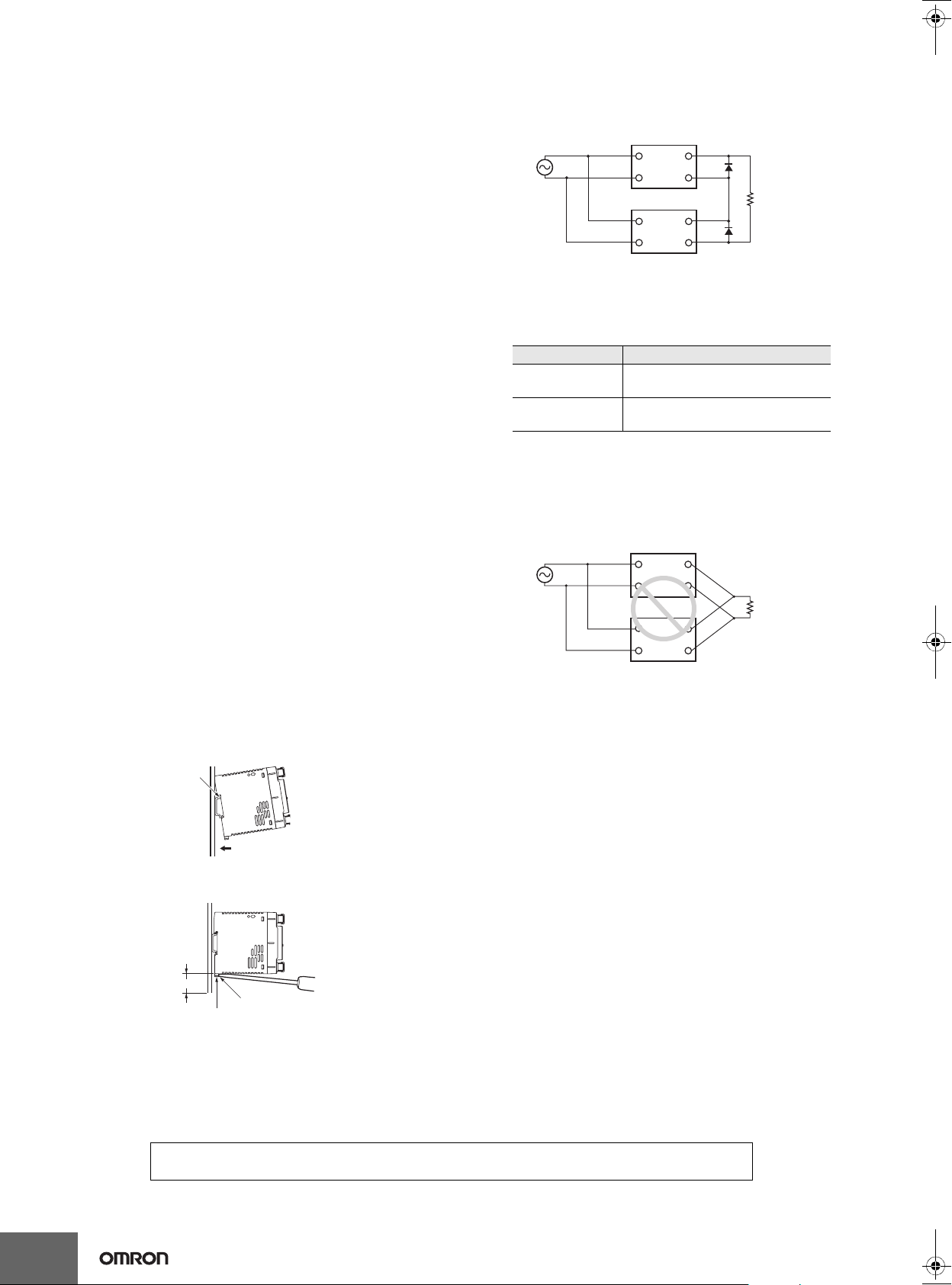
DIN Rail Mounting
To mount the Block on a DIN Rail, hook portion (A) of the Block onto
the rail and press the Block in direction (B).
(A)
(B)
To dismount the Block, pull down portion (C) with a flat-blade
screwdriver and pull out the Block.
Series Operation
Two power supplies can be connected in series.
Correct
AC (L)
AC (N)
AC (L)
AC (N)
+V
−V
+V
−V
Note: 1. The diode is connected as shown in the figure. If the load is
short-circuited, a reverse voltage will be generated inside
the Power Supply. If this occurs the Power Supply may
possibly deteriorate or be damaged. Always connect a
diode as shown in the figure.
Select a diode having the following ratings.
Type Schottky Barrier diode
Dielectric strength
RRM)
(V
Forward current
F)
(I
Twice the rated output voltage or
above
Twice the rated output current or
above
2. Although Products having different specifications can be
connected in series, the current flowing through the load
must not exceed the smaller rated output current.
Parallel Operation
The Product is not designed for parallel operation.
Incorrect
AC (L)
AC (N)
AC (L)
AC (N)
+V
−V
+V
−V
In Case There Is No Output Voltage
The possible cause for no output voltage may be that the overcurrent
or overvoltage protection has operated. The internal protection may
operate if a large amount of surge voltage such as a lightening surge
occurs while turning ON the power supply.
In case there is no output voltage, please check the following points
before contacting us:
• Checking overload protected status:
Check whether the load is in overload status or is short-circuited.
Remove wires to load when checking.
• Checking overvoltage or internal protection (except for 15 W
models):
Turn the power supply OFF once, and leave it OFF for at least 3
minutes. Then turn it ON again to see if this clears the condition.
Cat.No. T01E-EN-02_OEE
12
Buzzing Noise When the Input Is Turned ON
(120 W, 240 W, and 480 W Models)
30 mm min.
Track stopper
(C)
ALL DIMENSIONS SHOWN ARE IN MILLIMETERS.
To convert millimeters into inches, multiply by 0.03937. To convert grams into ounces, multiply by 0.03527.
In the interest of product improvement, specifications are subject to change without notice.
A harmonic current suppression circuit is built into the Power Supply.
This circuit can create noise when the input is turned ON, but it will
last only until the internal circuits stabilize and does not indicate any
problem in the Product.
 Loading...