

Page 1
Switch Mode Power Supply S8VM 1
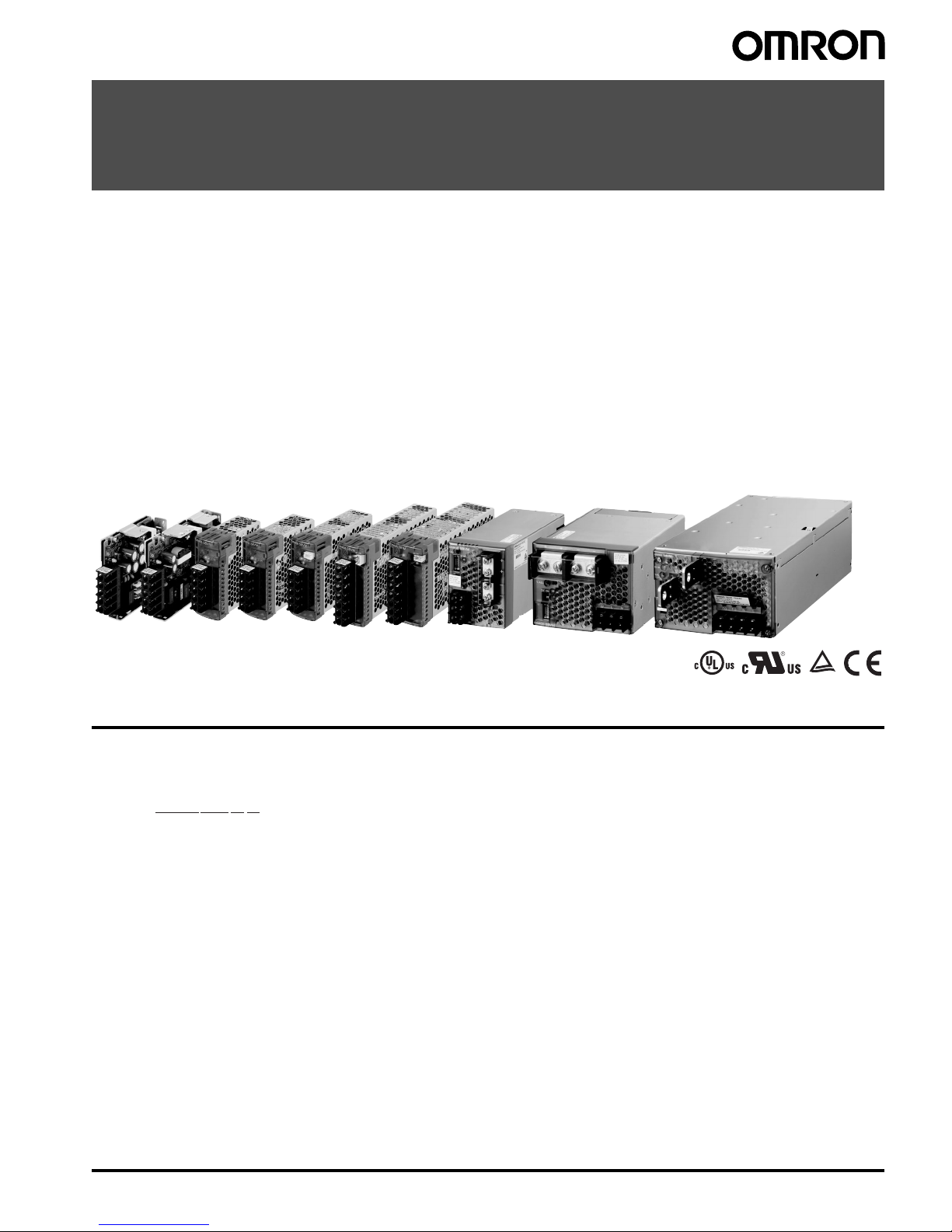
Switch Mode Power Supply
S8VM (15/30/50/100/150/300/600/1,500-W Models)
Power Supply Featuring OMRON’s Unique, New Undervoltage Alarm Function with
Compact Body Contributing to Machine Downsizing
• New undervoltage alarm function ass is ts in determining ca use s of errors (S8VM- @@@24A@/P@ only).
• Power failure alarm function provides notification of output voltage errors (300-, 600-, and 1,500-W models only).
• Broad range of possibilities with 8 capacities and 29 models to choose from.
• RoHS-compliant including lead-free construction.
• Safety standards: UL508/60950-1/1604, CSA C22.2 No. 14/No. 60950-1/No. 213, EN50178, EN60950-1 (The 300-, 600-, and
1,500-W models will not conform to safety standards if the customer replaces the fan.)
• Harmonic current emissions: Conforms to EN61000-3-2 (except for 15- and 30-W models).
• New, attentive design prevents screws from falling out of terminal block (except for output terminals of 300-, 600-, and 1,500-W
models).
• Finger protection prevents electric shock.
• DIN Rail mounting.
Model Number Structure
■Model Number Lege nd
Note: Not all combinations are possible. Please refer to the list of models in Ordering Information on page 2.
Note: 1. The housing and terminal of the connector for the undervoltage alarm output are provided with the S8VM-05024A@/P@, S8VM-
10024A@/P@ and S8VM-15024A@/P@.
2. Bottom mounting models cannot be used for front mounting. For a front mounting configuration, use a DIN Rail mounting brack et m odel
or Mounting Brackets (sold separately).
3. A forced-air cooling method with a fan is used with 300-, 600-, and 1,500-W models.
Note: Refer to Precautions for Safe Use on page 32.
12
3
4
S8VM- @@@@@@@
1. Power Ratings
015: 15 W
030: 30 W
050: 50 W
100: 100 W
150: 150 W
300: 300 W
600: 600 W
152: 1,500 W
2. Output Voltage
05: 5 V
12: 12 V
15: 15 V
24: 24 V
3. Configuration/Functions
None: Open-frame type Standard type
C: Covered type Standard type
A: Covered type Undervoltage alarm type (Sinking)
(See note 1.)
P: Covered type Undervoltage alarm type (Sourcing)
(See note 1.)
4. Configuration
None: Bottom mounting type (See note 2.)
D: DIN Rail mounting bracket type
Page 2
2 Switch Mode Power Supply S8VM
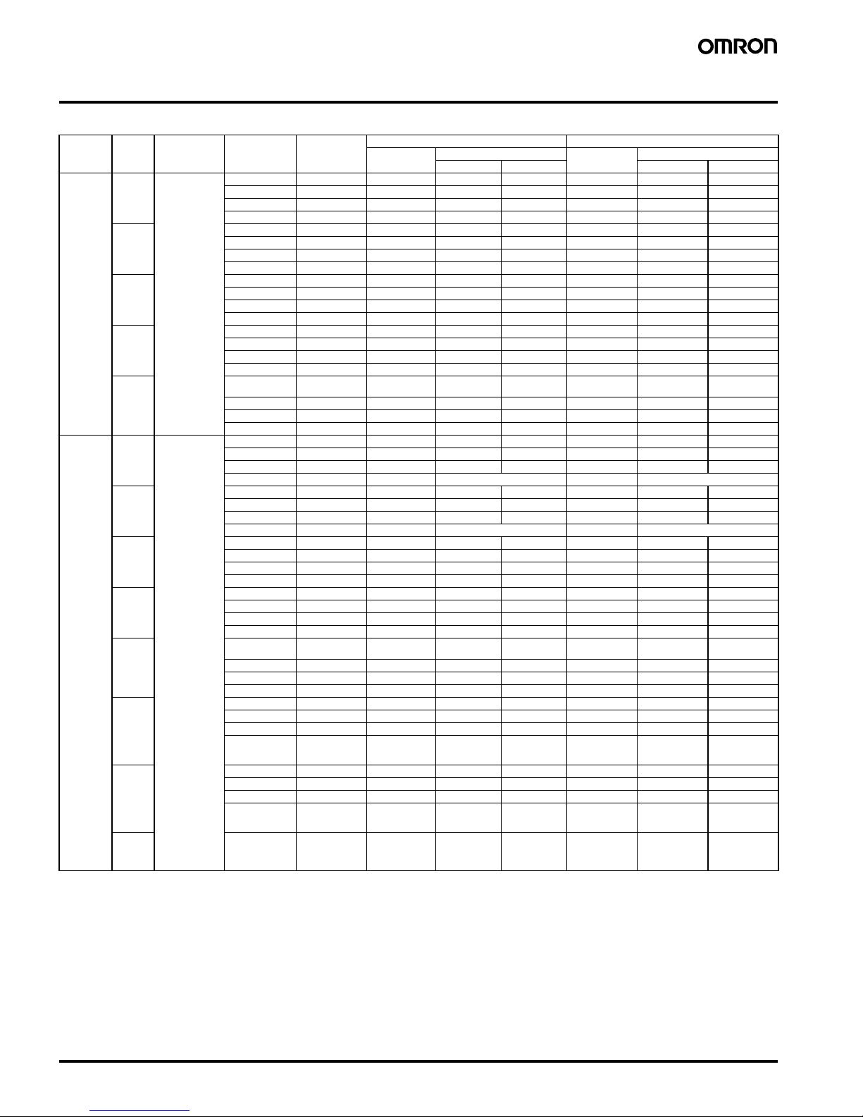
Ordering Information
Note: For details on normal stock models, contact your nearest OMRON representative.
Note: 1. No outputs are built into these models.
2. The output capacity of the S8VM-15005@@ is 135 W.
3. M8 bolts and nuts for the output terminals are not included with the S8VM-15224C.
4. The 300-, 600-, and 1,500-W models have fans.
5. To perform front mounting using the bottom mounting models, use the Mounting Brackets (S82Y-VM@@F, sold separately).
Configura-
tion
Power
ratings
Input voltage Output voltage Output current Bottom mounting DIN Rail mounting bracket
Standard model Undervoltage alarm model Standard model Undervoltage alarm model
Sinking Sourcing Sinking Sourcing
Open-frame
type
15 W 100 to 240 VAC 5 V 3 A S8VM-01505 --- --- S8VM-01505D --- ---
12 V 1.3 A S8VM-01512 --- --- S8VM-01512D --- --15 V 1 A S8VM-01515 --- --- S8VM-01515D --- --24 V 0.65 A S8VM-01524 --- --- S8VM-01524D --- ---
30 W 5 V 6 A S8VM-03005 --- --- S8VM-03005D --- ---
12 V 2.5 A S8VM-03012 --- --- S8VM-03012D --- --15 V 2 A S8VM-03015 --- --- S8VM-03015D --- --24 V 1.3 A S8VM-03024 --- --- S8VM-03024D --- ---
50 W 5 V 10 A S8VM-05005 --- --- S8VM-05005D --- ---
12 V 4.3 A S8VM-05012 --- --- S8VM-05012D --- --15 V 3.5 A S8VM-05015 --- --- S8VM-05015D --- --24 V 2.2 A S8VM-05024 --- --- S8VM-05024D --- ---
100 W 5 V 20 A S8VM-10005 --- --- S8VM-10005D --- ---
12 V 8.5 A S8VM-10012 --- --- S8VM-10012D --- --15 V 7 A S8VM-10015 --- --- S8VM-10015D --- --24 V 4.5 A S8VM-10024 --- --- S8VM-10024D --- ---
150 W 5 V 27 A S8VM-15005
(See note 2.)
--- --- S8VM-15005D
(See note 2.)
--- ---
12 V 12.5 A S8VM-15012 --- --- S8VM-15012D --- --15 V 10 A S8VM-15015 --- --- S8VM-15015D --- --24 V 6.5 A S8VM-15024 --- --- S8VM-15024D --- ---
Covered
type
15 W 100 to 240 VAC 5 V 3 A S8VM-01505C --- --- S 8VM-01505CD --- ---
12 V 1.3 A S8VM-01512C --- --- S8VM-01512CD --- --15 V 1 A S8VM-01515C --- --- S8VM-01515CD --- --24 V 0.65 A S8VM-01524C S8VM-01524A (See note 1.) S8VM-01524CD S8VM-01524AD (See note 1.)
30 W 5 V 6 A S8VM-03005C --- --- S8VM-03005CD --- ---
12 V 2.5 A S8VM-03012C --- --- S8VM-03012CD --- --15 V 2 A S8VM-03015C --- --- S8VM-03015CD --- --24 V 1.3 A S8VM-03024C S8VM-03024A (See note 1.) S8VM-03024CD S8VM-03024AD (See note 1.)
50 W 5 V 10 A S8VM-05005C --- --- S8VM-05005CD --- ---
12 V 4.3 A S8VM-05012C --- --- S8VM-05012CD --- --15 V 3.5 A S8VM-05015C --- --- S8VM-05015CD --- --24 V 2.2 A S8VM-05024C S8VM-05024A S8VM-05024P S8VM-05024CD S8VM-05024AD S8VM-05024PD
100 W 5 V 20 A S8VM-10005C --- --- S 8VM-10005CD --- ---
12 V 8.5 A S8VM-10012C --- --- S8VM-10012CD --- --15 V 7 A S8VM-10015C --- --- S8VM-10015CD --- --24 V 4.5 A S8VM-10024C S8VM-10024A S8VM-10024P S8VM-10024CD S8VM-10024AD S8VM-10024PD
150 W 5 V 27 A S8VM-15005C
(See note 2.)
--- --- S8VM-15005CD
(See note 2.)
--- ---
12 V 12.5 A S8VM-15012C --- --- S8VM-15012CD --- --15 V 10 A S8VM-15015C --- --- S8VM-15015CD --- --24 V 6.5 A S8VM-15024C S8VM-15024A S8VM-15024P S8VM-15024CD S8VM-15024AD S8VM-15024PD
300 W
(See note
4.)
5 V 60 A S8VM-30005C --- --- --- --- --12 V 27 A S8VM-30012C --- --- --- --- --15 V 22 A S8VM-30015C --- --- --- --- --24 V 14 A
Peak current:
16.5 A (200 VA C)
S8VM-30024C --- --- --- --- ---
600 W
(See note
4.)
5 V 120 A S8VM-60005C --- --- --- --- --12 V 53 A S8VM-60012C --- --- --- --- --15 V 43 A S8VM-60015C --- --- --- --- --24 V 27 A
Peak current:
31 A (200 VAC)
S8VM-60024C --- --- --- --- ---
1,500 W
(See note
4.)
24 V 65 A (100 VAC)
70 A (200 VAC)
Peak current:
105 A (200 VAC)
S8VM-15224C
(See note 3.)
--- --- --- --- ---
Page 3
Switch Mode Power Supply S8VM 3
Specifications
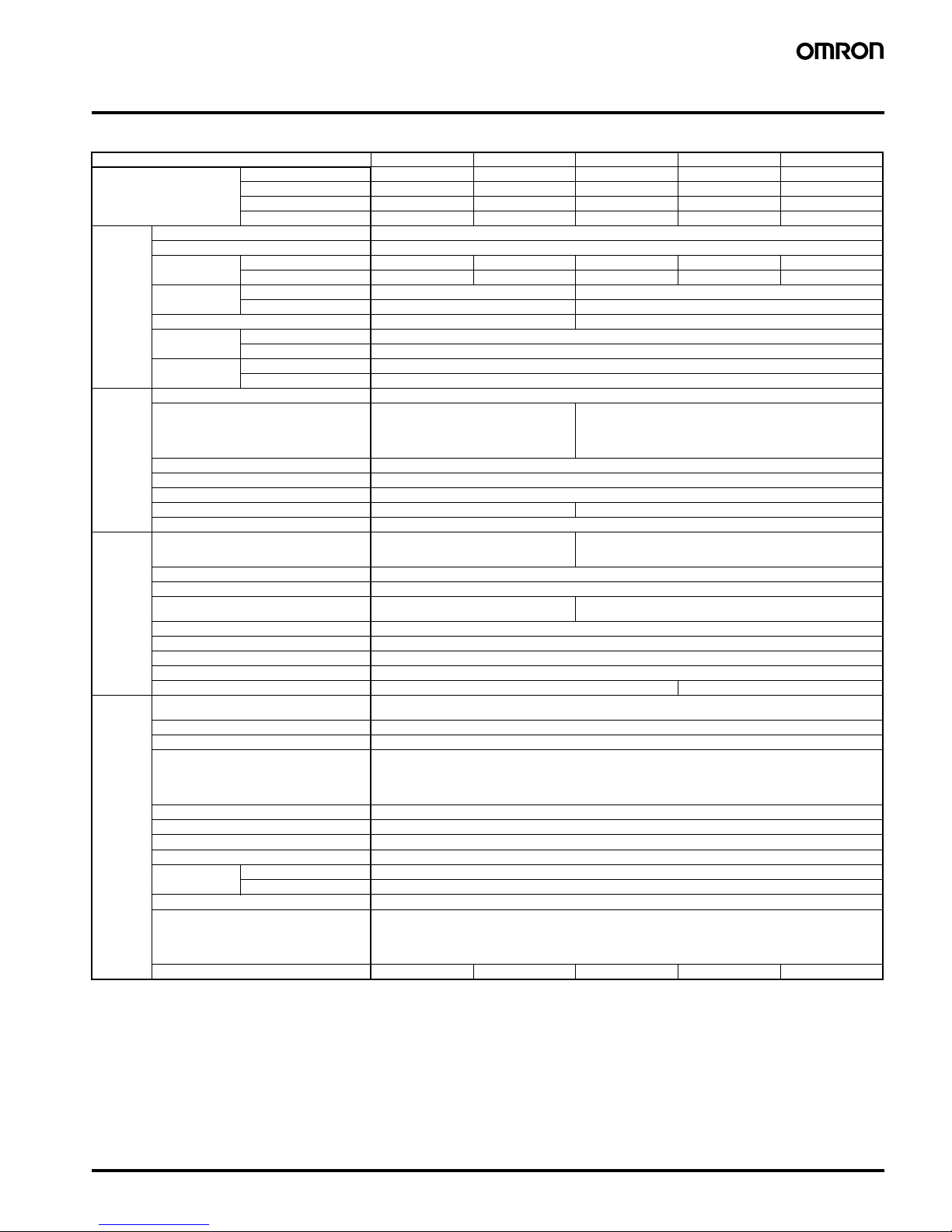
■Ratings/Characteristics
Note: 1. Do not use the Inverter o utput for the Power Supply. Inverters with an output frequency of 50/60 Hz are available, but the rise in the internal temperature of the Power
Supply may result in ignition or burning.
2. Refer to the Engineering Data (15-W, 30-W, 50-W, 100-W, 150-W Models) section on page 9 to 11 for details.
3. If the V. ADJ adjuster is turned, the voltage will increase by more than +20% of the voltage adjustment range.
When adjusting the output voltage, confirm the actual output voltage from the Power Supply and be sure that the load is not damaged.
4. To reset the protection, turn OFF the input power for three minutes or longer and then turn it back ON.
5. Conducted emissions: The noise value is affected by factors such as the wiring method. The Power Supply conforms to Class B when the aluminum plate is laid under
the Power Supply. For 15-W models, insert a clamp filter (ZCAT2436-1330 by TDK: 50 Ω min. [50 to 500 MHz], or the equivalent) in the output wire to reduce noise.
6. Radiated emissions: The noise value is affected by factors such as the wiring method. The Power Supply conforms to Class B when the aluminum plate is laid under the
Power Supply. For 150-W models, insert a clamp filter (ZCAT2017-0930 by TDK: 35 Ω min. [50 to 500 MHz], or the equivalent) in the input wire to reduce noise.
7. The weight indicated is for bottom mounting, open-frame models.
8. A@: Sinking type (NPN)
P@: Sourcing type (PNP)
Item Power rating 15 W 30 W 50 W 100 W 150 W
Efficiency 5-V models 75% min. 75% min. 80% min. 81% min. 81% min.
12-V models 78% min. 79% min. 79% min. 81% min. 81% min.
15-V models 78% min. 79% min. 79% min. 81% min. 81% min.
24-V models 80% min. 81% min. 80% min. 82% min. 83% min.
Input Voltage (See note 1.) 100 to 240 VAC (85 to 264 VAC)
Frequency (See note 1.) 50/60 Hz (47 to 63 Hz)
Current 100-V input 0.5 A max. 0.9 A max. 0.8 A max. 1.4 A max. 2.0 A max.
200-V input 0.25 A max. 0.45 A max. 0.4 A max. 0.7 A max. 1.0 A max.
Power factor 100-V input --- 0.98 min.
200-V input --- 0.94 min.
Harmonic current emissions --- Conforms to EN 61000-3-2
Leakage current 100-V input 0.4 mA max. (at rated output)
200-V input 0.75 mA max. (at rated output)
Inrush current
(See note 2.)
100-V input 17.5 A max. (for cold start at 25°C)
200-V input 35 A max. (for cold start at 25°C)
Output Voltage adjustment range (See note 3.) −20% to 20% (with V. ADJ) (S8VM-@@@24A@/P@: −10% to 20%)
Ripple 3.2% (p-p) max. (5 V),
1.5% (p-p) max. (12 V),
1.2% (p-p) max. (15 V),
1.0% (p-p) max. (24 V),
(at rated input/output voltage)
3.2% (p-p) max. (5 V),
1.5% (p-p) max. (12 V),
1.2% (p-p) max. (15 V),
0.75% (p-p) max. (24 V),
(at rated input/output voltage)
Input variation influence 0.4% max. (at 85 to 264 VAC input, 100%)
Load variation influence (rated input voltage) 0.8% max. (with rated input, 0 to 100% load)
Temperature variation influence 0.02%/°C max.
Start up time (See note 2.) 1,100 ms max. (at rated input/output voltage) 800 ms max. (at rated input/output voltage)
Hold time (See note 2.) 20 ms typ. (15 ms min.) (at rated input/output voltage)
Additional
functions
Overload protection (See note 2.) 105% to 160% of rated load current, voltage
drop, intermittent, automatic reset
105% to 160% of rated load current,
voltage drop (12 V, 15 V, and 24 V),
voltage drop, intermittent (5 V), automatic reset
Overvoltage protection (See note 2.) Yes (See note 4.)
Undervoltage alarm indication Yes (color: yellow (DC LOW1), red (DC LOW2)) (S8VM-@@@24A@/P@ only)
Undervoltage alarm output No Yes (S8VM-@@@24A@/P@ only)
(Transistor output), 30 VDC max., 50 mA max. (See note 8.)
Power failure alarm indication No
Power failure alarm output No
Series operation Yes
Parallel operation No
Remote sensing function No Yes
Other Ambient operating temperature Refer to the derating curve in Engineering Data (15-W, 30-W, 50-W, 100-W, 150-W Models). (with no icing or con-
densation) (See note 2.)
Storage temperature −25 to 65°C
Ambient operating humidity 30% to 85% (Storage humidity: 25% to 90%)
Dielectric strength 3.0 kVAC for 1 min. (between all inputs and outputs; detection current: 20 mA)
2.0 kVAC for 1 min. (between all inputs and PE/FG terminals; detection current: 20 mA)
500 VAC for 1 min. (between all outputs and PE/FG terminals; detection current: 100 mA)
500 VAC for 1 min. (between all outputs (except the detection output terminals) and detection output terminals; detection current: 20 mA) (S8VM-@@@24A@/P@ only)
Insulation resistance 100 MΩ min. (between all outputs and all inputs, PE/FG terminals) at 500 VDC
Vibration resistance 10 to 55 Hz, 0.375-mm single amplitude for 2 hours each in X, Y, and Z directions
Shock resistance
150 m/s
2
, 3 times each in ±X, ±Y, ±Z directions
Output indicator Yes (color: green)
EMI Conducted Emission Conforms to EN61204-3 EN55011 Class B and based on FCC Class B (See note 5.)
Radiated Emission Conforms to EN61204-3 EN55011 Class B (See note 6.)
EMS Conforms to EN61204-3 High severity levels
Approved standards UL: UL508 (Listing), UL60950-1, UL1604 (Class I/Division 2, Listing)
CSA: cUL: C22.2 No.14, No.213 (Class I/Division 2), cUR: No. 60950-1
EN: EN50178, EN60950-1
SELV (EN60950-1)
According to VDE0160/P100 SEMI-F47 (200 VAC input)
Weight (See note 7.) 180 g max. 220 g max. 290 g max. 460 g max. 530 g max.
Page 4
4 Switch Mode Power Supply S8VM
Note: 1. Do not use the Inverter output for the Power Supply. Inverters with an output frequency of 50/60 Hz are available, but the rise in the internal t e mperature of
the Power Supply may result in ignition or burning.
2. Refer to the Engineering Data section on page 15 to 17 for details.
3. If the V. ADJ adjuster is turned, the voltage will increase by more than +20% of the voltage adjustment range. When adjusting the output vol ta ge, confi rm th e
actual output voltage from the Power Supply and be sure that the load is not damaged.
4. To reset the protection, turn OFF the input power for three minutes or longer and then turn it back ON. Alternatively, turn OFF the remote control signal and
then turn it back ON again.
5. Conducted emissions: The noi s e value i s affected by factors su ch as t he wi r ing m etho d. Th e Power Supply con form s to Class B when the alu minum pl a te
is laid under the Power Supply. For 600-W models, insert a clamp filter (ZCAT3035-1330 by TDK: 100
Ω min. [50 to 500 MHz], or the equivalent) in the input
wire, and ring core (HF60T38X14X22 by TDK: 16
Ω typ. [1 MHz], 46 Ω typ. [10 MHz] , or the equivalent) in the output wire to reduce noise
6. Radiated emissions: The noise value is affected by factors such as th e wi r in g me tho d. T he Power Supply conform s to C la ss A when the aluminum plate is
laid under the Power Supply (1,500-W models).
7. The measuring method conforms to JEITA standard RC-9131A. Refer to Ripple under Safety Precautions on page 34.
8. The Power Supply will not conform to safety standards if the customer replaces the fan.
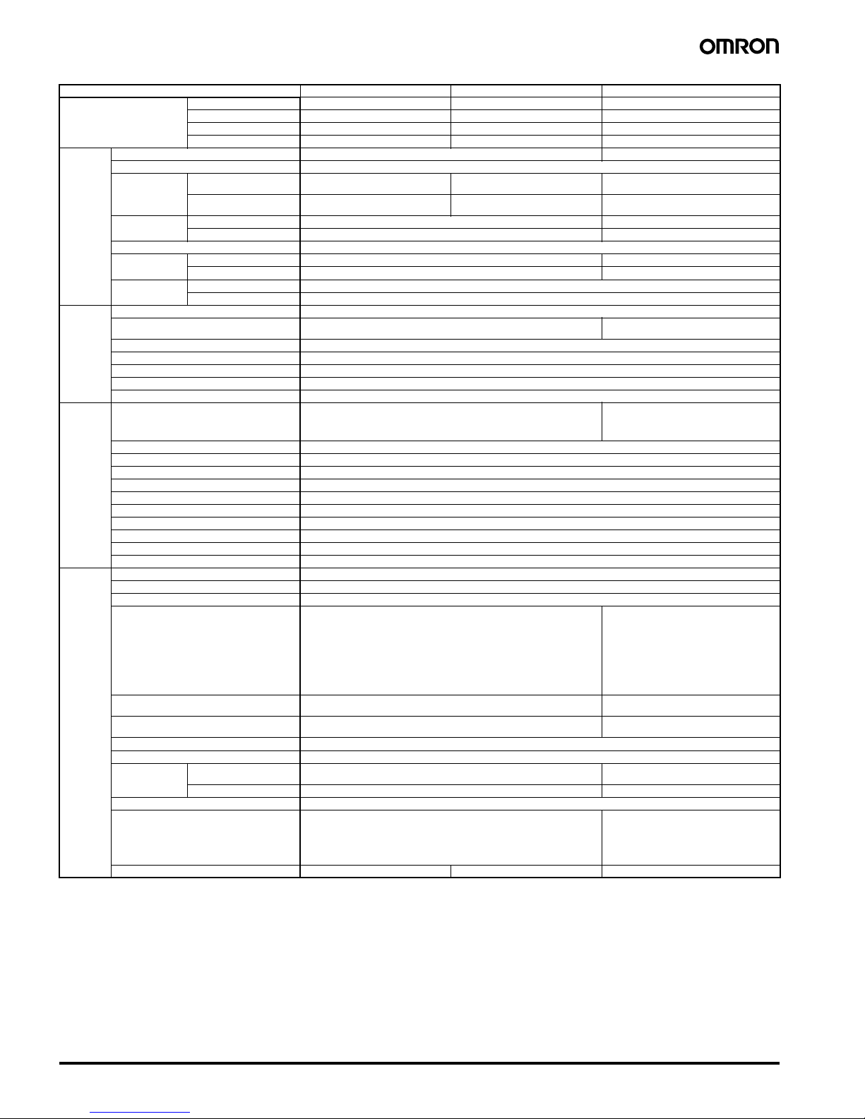
Item Power rating 300 W 600 W 1,500 W
Efficiency 5-V models 77% min. 77% min. ---
12-V models 78% min. 79% min. ---
15-V models 79% min. 80% min. ---
24-V models 81% min. 81% min. 82% min.
Input Voltage (See note 1.) 100 to 240 VAC (85 to 264 VAC) 100 to 240 VAC (85 to 265 VAC)
Frequency (See note 1.) 50/60 Hz (47 to 63 Hz)
Current 100-V input 4.0 A max. (5 V)
4.3 A max. (12 V, 15 V, and 24 V)
8.0 A max. (5 V)
8.3 A max. (12 V, 15 V, and 24 V)
20.0 A max.
200-V input 2.0 A max. (5 V)
2.2 A max. (12 V, 15 V, and 24 V)
4.0 A max. (5 V)
4.2 A max. (12 V, 15 V, and 24 V)
11.0 A max.
Power factor 100-V input 0.98 min. 0.97 min.
200-V input 0.94 min. 0.93 min.
Harmonic current emissions Conforms to EN61000-3-2
Leakage current 100-V input 0.4 mA max. 1.5 mA max.
200-V input 0.75 mA max. 1.5 mA max.
Inrush current
(See note 2.)
100-V input 20 A max. (for cold start at 25°C)
200-V input 40 A max. (for cold start at 25°C)
Output Voltage adjustment range (See note 3.) −20% to 20% (with V. ADJ)
Ripple 3.8% (p-p) max. (5 V), 2.0% (p-p) max. (12 V), 2.0% (p-p) max. (15 V),
1.25% (p-p) max. (24 V), (at rated input/output voltage)
1.25% (p-p) max. (See note 7.),
(at rated input/output voltage)
Input variation influence 0.4% max. (at 85 to 264 VAC input, 100%)
Load variation influence (rated input voltage) 0.6% max. (with rated input, 0 to 100% load)
Temperatu re va riatio n influ en ce 0.02%/°C max.
Start up time (See note 2.) 1,000 ms max. (at rated input/output voltage)
Hold time (See note 2.) 20 ms typ. (15 ms min.) (at rated input/output voltage)
Additional
functions
Overload protection (See note 2.) 105% to 160% of rated load current (5 V, 12 V, and 15 V ), 120% to 160% of rated
load current (S8VM-30024C), 115% to 160% of rated load current (S8VM60024C), voltage drop (12 V, 15 V, and 24 V), voltage drop, intermittent (5 V),
automatic reset
105% to 160% of rated load curr ent (100 VAC),
155% to 200% of rated load curr ent (200 VAC),
voltage drop, automatic reset (Turns OFF
when continuous for 5 s min.) (See note 4.)
Overvoltage protection (See note 2.) Yes (See note 4.)
Overheat protection (See note 2.) Yes (See note 4.)
Undervoltage alarm indication No
Undervoltage alarm output No
Power failure alarm indication Yes (color: red)
Power failure alarm output Yes (Transistor output), 30 VDC max., 50 mA max.
Series operation Yes
Parallel operation Yes (Up to 2 units)
Remote sensing function Yes
Remote control function Yes
Other Ambient operating temperature Refer to the derating curve in Engineering Data (300-W, 600-W, 1,500-W Models). (with no icing or condensation) (See note 2.)
Storage temperature −25 to 65°C
Ambient operating humidity 30% to 85% (Storage humidity: 25% to 90%)
Dielectric strength 3.0 kVAC for 1 min. (between all inputs and outputs; detection current: 20 mA)
2.0 kVAC for 1 min. (between all inputs and PE terminals; detection current: 20
mA)
500 VA C for 1 min. (be tween all outputs and PE terminals; dete ction current: 100
mA)
100 VA C for 1 m in. (between all outp uts and RC terminals; detecti on current: 100
mA)
500 VAC for 1 min. (b etween all outputs and PF terminals; detection current: 20
mA)
3.0 kVAC for 1 min. (between all inputs and
outputs; detection current: 20 mA)
2.0 kVA C f or 1 mi n. (between all inputs a nd FG
terminals; detection current: 20 mA)
500 VAC for 1 min. (between all outputs and
FG terminals; detection current: 300 mA)
100 VAC for 1 min. (between all outputs and
RC terminals; detection current: 100 mA)
500 VAC for 1 min. (between all outputs and
PF terminals; detection current: 20 mA)
Insulation resistance 100 MΩ min. (between all outputs and all inputs, PE terminals) at 500 VDC 100 MΩ min. (between all outputs and all in-
puts, FG terminals) at 500 VDC
Vibration resistance 10 to 55 Hz, 0.375-mm single a mplitude fo r 2 hours e ach in X, Y, and Z directions 10 to 55 Hz, 0.15-mm single amplitude for 2
hours each in X, Y, and Z directions
Shock resistance
150 m/s2, 3 times each in ±X, ±Y, ±Z directions
Output indicator Yes (color: green)
EMI Conducted Emission Conforms to EN61204-3 EN55011 Class B and based on FCC Class B Conforms to EN61204-3 EN55011 Class A
and based on FCC Class A
Radiated Emission Conforms to EN61204-3 EN55011 Class B Conforms to EN61204-3 EN55011 Class A
EMS Conforms to EN61204-3 High severity levels
Approved standards (See note 8.) UL: UL508 (Recognition) (5 V, 12 V, and 15 V)
UL508 (Listing) (24 V), UL60950-1
UL1604 (Class I/Division 2, Listing) (24 V) (pending)
CSA: cUL: C22.2 No.14, cUR: CSA No. 60950-1
EN: EN50178, EN60950-1
SEMI-F47 (200 VAC input)
UL: UL508 (Recognition), UL60950-1
cUR: CSA C22.2 No.14, No. 60950-1
EN: EN50178, EN60950-1
SEMI-F47 (200 VAC input)
Weight 1,100 g max. 1,700 g max. 3,800 g max.
Page 5
Switch Mode Power Supply S8VM 5
Connections
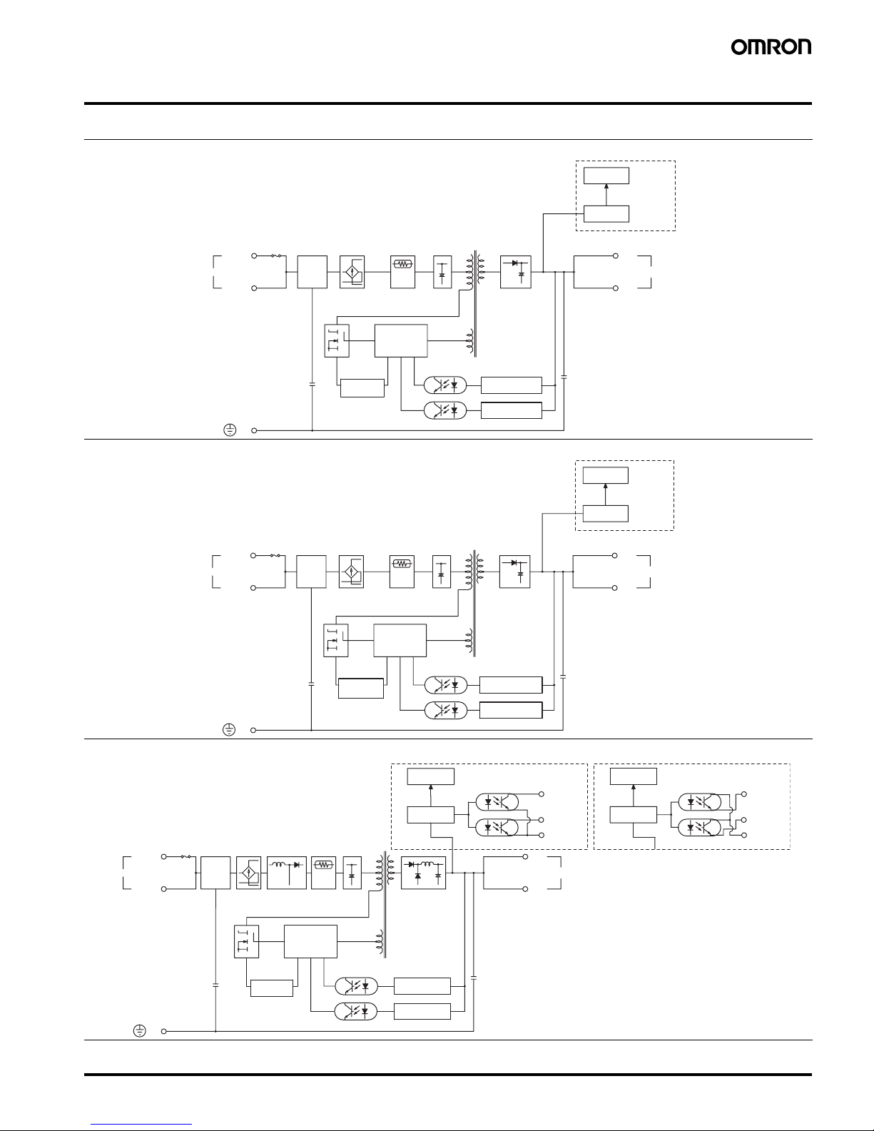
■Block Diagrams
Noise
filter
Overvoltage
detection circuit
Fuse
2 A
Rectifier/smoothing
circuit
Drive control
circuit
AC (L)
AC (N)
INPUT
/FG
Photocoupler
DC OUTPUT
−V
+V
Voltage
detection circuit
Rectification Smoothing
Overcurrent
detection circuit
Inrush
current
protection circuit
Undervoltage
detection
S8VM-01524A@
Undervoltage
alarm indication
DC LOW1
DC LOW2
S8VM-015@@@@ (15 W)
Noise
filter
Fuse
3.15 A
AC (L)
AC (N)
INPUT
DC OUTPUT
−V
+V
Undervoltage
detection
Undervoltage
alarm indication
DC LOW1
DC LOW2
S8VM-03024A@
/FG
Overvoltage
detection circuit
Rectifier/smoothing
circuit
Drive control
circuit
Photocoupler
Voltage
detection circuit
Rectification Smoothing
Inrush
current
protection circuit
Overcurrent
detection circuit
S8VM-030@@@@ (30 W)
Fuse
2 A
AC (L)
AC (N)
INPUT
DC OUTPUT
−V
+V
Alarm
DC LOW1
Common
Inrush
current
protection
circuit
Undervoltage
detection
Alarm
DC LOW2
S8VM-05024A@ (Sinking)
DC LOW1
DC LOW2
Undervoltage
alarm indication
/FG
Noise
filter
Overvoltage
detection circuit
Rectifier/smoothing
circuit
Drive control
circuit
Photocoupler
Voltage
detection circuit
Rectification
Smooth-
ing
Harmonic
current
suppression
Photocoupler
Overcurrent
detection circuit
Alarm
DC LOW1
Common
Undervoltage
detection
Alarm
DC LOW2
S8VM-05024P@ (Sourcing)
DC LOW1
DC LOW2
Undervoltage
alarm indication
Photocoupler
S8VM-050@@@@ (50 W)
Page 6
6 Switch Mode Power Supply S8VM
DC OUTPUT
−V
+V
Alarm
DC LOW1
Common
Undervoltage
detection
Alarm
DC LOW2
INPUT
AC (N)
AC (L)
Fuse
3.15 A
Drive
S8VM-10024A@ (Sinking)
Remote sensing
+S
−S
DC LOW1
DC LOW2
Undervoltage
alarm indication
/FG
Inrush
current
protection
circuit
Noise
filter
Overvoltage
detection circuit
Rectifier/smoothing
circuit
Drive control
circuit
Photocoupler
Voltage
detection circuit
Rectification
Smooth-
ing
Overcurrent
detection circuit
Harmonic
current
suppression
Photocoupler
Alarm
DC LOW1
Common
Undervoltage
detection
Alarm
DC LOW2
S8VM-10024P@ (Sourcing)
DC LOW1
DC LOW2
Undervoltage
alarm indication
Photocoupler
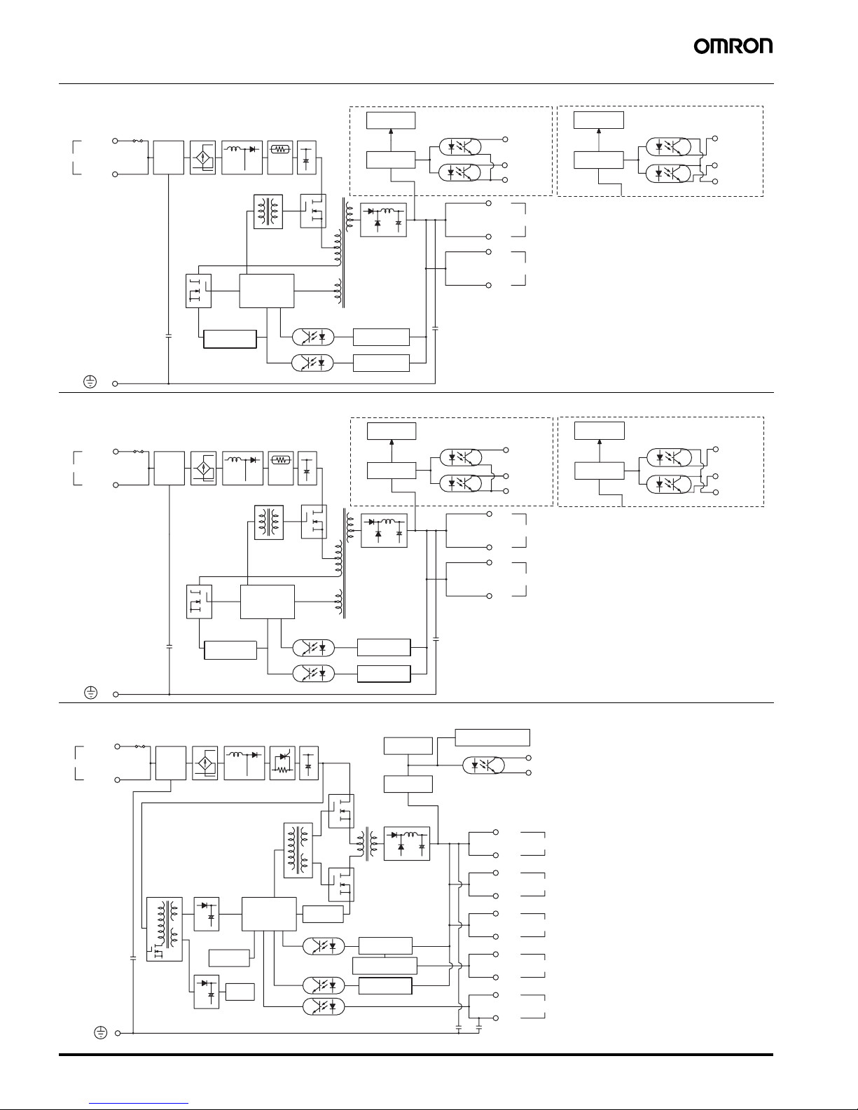
S8VM-100@@@@ (100 W)
DC OUTPUT
−V
+V
Alarm
DC LOW1
Common
Undervoltage
detection
Alarm
DC LOW2
INPUT
AC (N)
AC (L)
Fuse
5 A
Drive
Remote sensing
+S
−S
DC LOW1
DC LOW2
Undervoltage
alarm indication
S8VM-15024A@ (Sinking)
/FG
Inrush
current
protection
circuit
Noise
filter
Overvoltage
detection circuit
Rectifier/smoothing
circuit
Drive control
circuit
Photocoupler
Voltage
detection circuit
Rectification
Smooth-
ing
Harmonic
current
suppression
Photocoupler
Overcurrent
detection circuit
Alarm
DC LOW1
Common
Undervoltage
detection
Alarm
DC LOW2
S8VM-15024P@ (Sourcing)
DC LOW1
DC LOW2
Undervoltage
alarm indication
Photocoupler
S8VM-150@@@@ (150 W)
PF-E
PF
Power failure
alarm indication
Over heat
detection circuit
Fan
Power supply
balance circuit
Alarm
PF-C
INPUT
AC (N)
AC (L)
DC OUTPUT
−V
+V
Output voltage monito
r
−V
+V
Remote sensing
−S
+S
Current balance
CBG
CB
Remote control
−RC
+RC
Auxiliary power
supply circuit
Fan detection
Fuse
10 A
Noise
filter
Rectification
Harmonic
current
suppression
Inrush
current
protection
circuit
Smooth-
ing
Drive
Overcurrent
detection circuit
Control
circuit
Photocoupler
Photocoupler
Rectifier/smoothing
circuit
Rectifier/smoothing
circuit
Power failure
alarm detection
Rectifier/smoothing
circuit
Overvoltage
detection circuit
Voltage
detection circuit
S8VM-300@@C (300 W)
Page 7
Switch Mode Power Supply S8VM 7
PF-E
PF
Fan
Alarm
PF-C
INPUT
AC (N)
AC (L)
Drive
DC OUTPUT
−V
+V
−V
+V
−S
+S
CBG
CB
−RC
+RC
Power failure
alarm indication
Over heat
detection circuit
Remote sensing
Current balance
Remote control
Fuse
15 A
Noise
filter
Rectification
Harmonic
current
suppression
Inrush
current
protection
circuit
Smoothing
Overcurrent
detection circuit
Control
circuit
Photocoupler
Photocoupler
Rectifier/smoothing
circuit
Power failure
alarm detection
Rectifier/smoothing
circuit
Auxiliary power
supply circuit
Fan detection
Rectifier/smoothing
circuit
Power supply
balance circuit
Output voltage monito
r
Overvoltage
detection circuit
Voltage
detection circuit
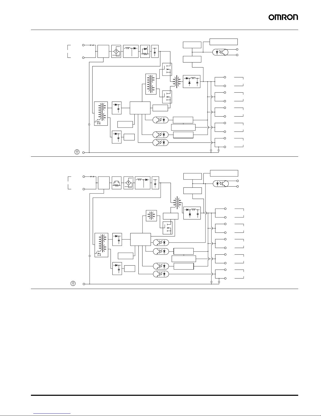
S8VM-600@@C (600 W)
PF-E
/FG
PF
Alarm
PF-C
INPUT
AC (N)
AC (L)
DC OUTPUT
−V
+V
−V
+V
−S
+S
CBG
CB
−RC
+RC
Fan
Drive
Power failure
alarm indication
Remote sensing
Current balance
Remote control
Fuse
30 A
Noise
filter
Rectification
Harmonic
current
suppression
Inrush
current
protection
circuit
Smoothing
Overcurrent
detection circuit
Control
circuit
Photocoupler
Photocoupler
Rectifier/smoothing
circuit
Power failure
alarm detection
Rectifier/smoothing
circuit
Rectifier/smoothing
circuit
Over heat
detection circuit
Auxiliary power
supply circuit
Power supply
balance circuit
Output voltage monito
r
Fan detection
Overvoltage
detection circuit
Voltage
detection circuit
S8VM-15224C (1,500 W)
Page 8
8 Switch Mode Power Supply S8VM
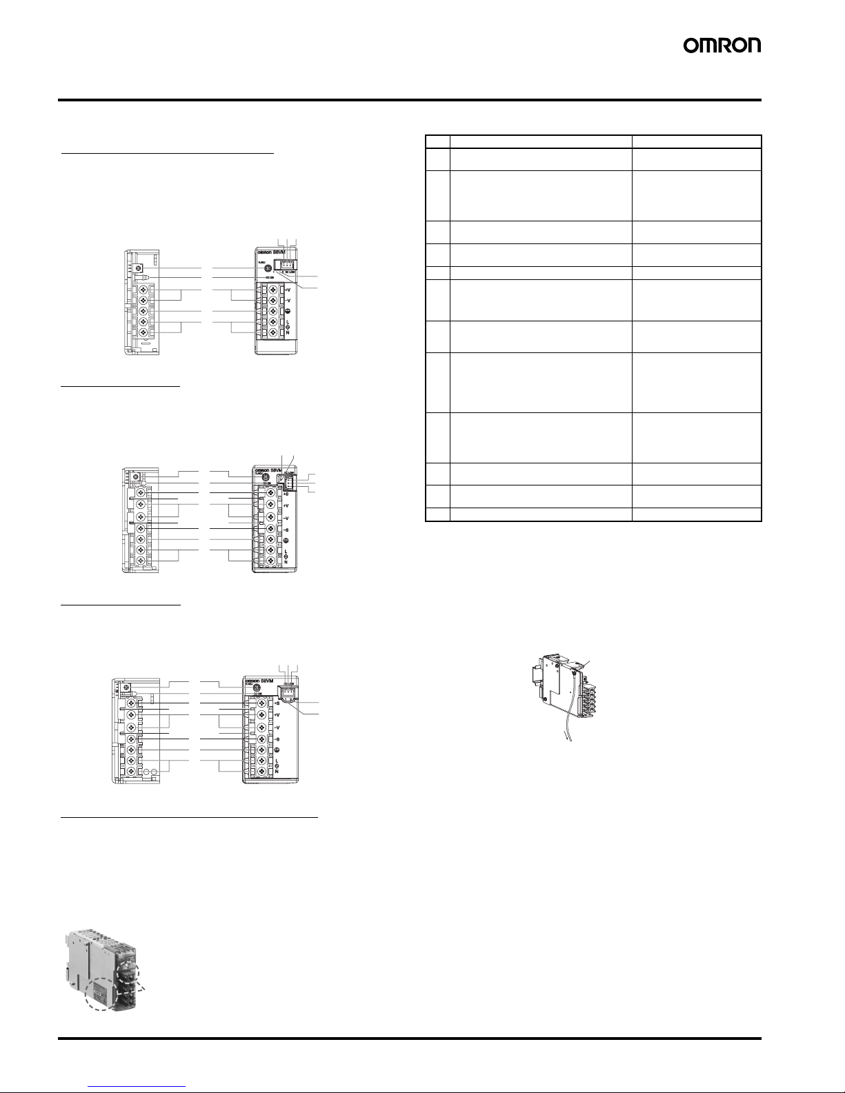
Construction and Nomenclature (15-W, 30-W, 50-W, 100-W, 150-W Models)
■Nomenclature
Note: 1. The fuse is located on the (L) side. It is NOT user-replace-
able.
2. If mounting is performed using a DIN Rail, the protective
earthing connection is the panel mounting hole shown in the
figure below.
(A protective earthing connection stipulated in safety standards is used. Connect the ground completely (S8VM@@@@@D only)).
Ground terminal: M3 (Depth: 8 mm max.)/Ground wire:
AWG 18
3. S8VM-@@@24A@/P@ only
4. S8VM-05024A@/P@, S8VM-10024A@/P@, S8 VM-
15024A@/P@ only . Housing and terminals of the connector
for undervoltage detection output are also provided. For details, refer to Undervoltage Alarm Output Connector Har-
ness Manufacture Method on page 33 under Safety
Precautions.
5. When not using the remote sensing function, leave the short
bar in the same state as when shipped.
6. A@ models: Common terminal (emitter)
P@ models: Common terminal (collector)
■Output Color Label
5
4
3
2
1
6
7
8910
12
12
1
2
11
8
9
1
0
3
11
4
5
67
12
12
1
2
11
3
11
4
5
12
12
6
7
8910
12
12
15-W, 30-W, 50-W Models
Open-frame Models Covered Models
S8VM-015@@/S8VM-015@@D
S8VM-030@@/S8VM-030@@D
S8VM-050@@/S8VM-050@@D
100-W Models
Open-frame Models Covered Models
S8VM-100@@/S8VM-100@@D S8VM-100@@C@/S8VM-10024A@/P@
150-W Models
Open-frame Models Covered Models
S8VM-150@@/S8VM-150@@D S8VM-150@@C@/S8VM-15024A@/P@
S8VM-015@@C@/S8VM-01524A@
S8VM-030@@C@/S8VM-03024A@
S8VM-050@@C@/S8VM-05024A@/P@
300-W, 600-W, 1,500-W Models
Note: Refer to page 14.
No. Name Function
1 AC input terminals (L), (N) Connect the input lines to
these terminals. (See note 1.)
2 PE terminal: Protective earthing terminal
(S8VM-@@@@@C@/S8VM-@@@@@A@/
S8VM-@@@@@P@)
FG terminal: Frame ground terminal
(S8VM-@@@@@/S8VM-@@@@@D)
Connect the ground line to this
terminal. (See note 2.)
3 DC output terminals (-V), (+V) Connect the load lines to these
terminals.
4 Output indicator (DC ON: Green) Lights (green) while a direct
current (DC) output is ON.
5 Output voltage adjuster (V. ADJ) Use to adjust the voltage.
6 Undervoltage alarm indicator 1
(DC LOW1: Yellow) (See note 3.)
Lights only when a momentary
drop in output voltage is de-
tected. This status is main-
tained.
7 Undervoltage alarm indicator 2
(DC LOW2: Red) (See note 3.)
Lights only when the output
voltage drops to approx imately
20 V or lower.
8 Undervoltage alarm output terminal 1:
(DC LOW1) (See note 4.)
Outputs only when a momen-
tary drop in output voltage is
detected. This status is main-
tained.
(The transistor turns OFF
when a voltage drop occurs.)
9 Undervoltage alarm output terminal 2:
(DC LOW2) (See note 4.)
Outputs only when the output
voltage drops to approx imately
20 V or lower.
(The transistor turns OFF
when a voltage drop occurs.)
10 Common terminal for undervoltage alarm
output (See note 4.)
Common terminal (See note
6.) for terminals 8 and 9
11 Remote sensing terminals (See note 5.) Correct the voltage drop in the
load lines.
12 Short bars (See note 5.) ---
Protective earthing
connection
Ground
Color label identifying output voltage
Green: 5 V
Blue: 12 V
Yellow: 15 V
White: 24 V
This color label identifies the output voltage by color.
Page 9
Switch Mode Power Supply S8VM 9
Engineering Data (15-W, 30-W, 50-W, 100-W, 150-W Models)
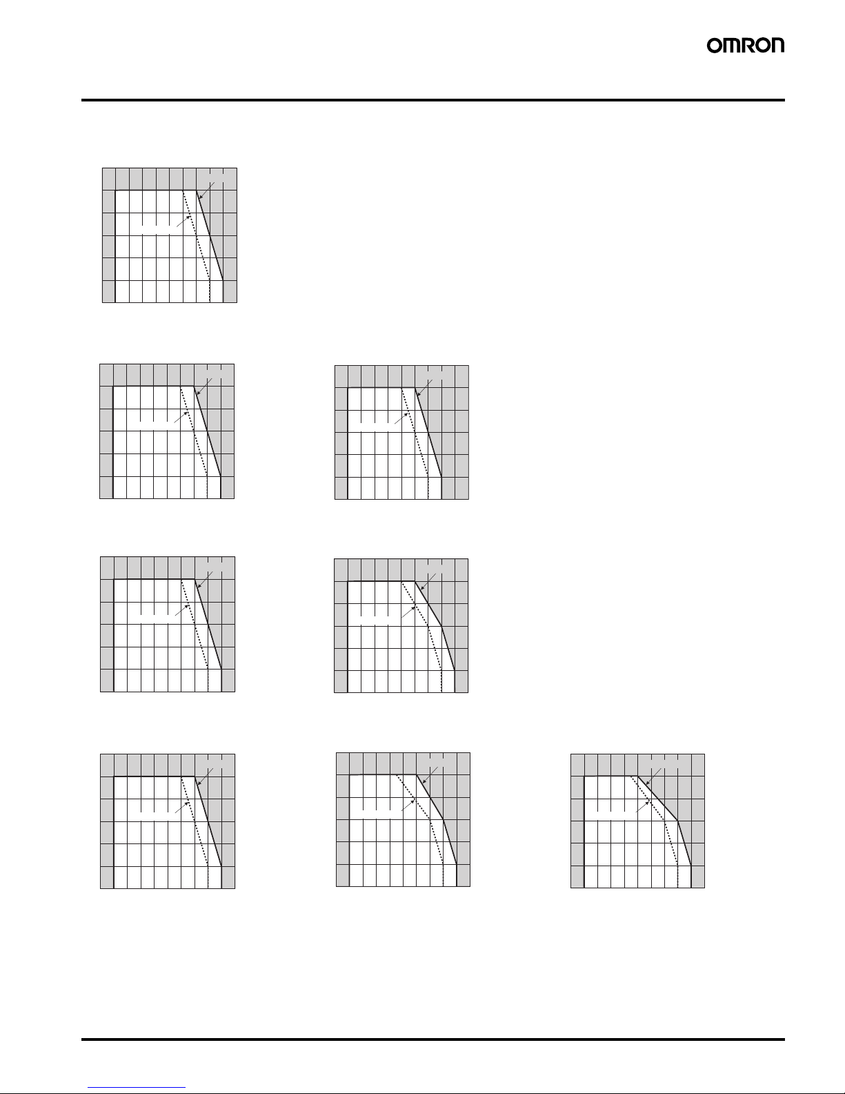
■Derating Curve
300W/600W/1,500W
Note: Refer to page 15.
Note: 1. Internal part s may occasionally be dete riorated or d amaged. Do no t use the Power Supply in areas outside the d erating cur ves (i.e., the area shown by
shading A in the above graphs).
2. If there is a derating problem, use forced air-cooling.
3. When mounting two or more Power Supplies side- by-side, allow at least 20 mm spacin g betw een th em. Mu ltiple 100- and 15 0-W models cannot be use d
side by side. Be sure to install the Power Supplies as far away from heat-generating sources as possible. As a reference value, allow at least 50 mm spacing
on the right and left sides. If only 20 mm spacing is allowed, use the Power Supply at a load ratio of 80% or less.
4. When using 150-W models for a long period of time at an input voltage of 90 VAC or lower, reduce the load to 80% or less of the above derating curves.
15W/30W
Standard Mounting/Horizontal Mounting/Face-u p Mou nting
50W
Standard Mounting/Horizontal Mounting
Face-up Mounting
100W
Standard Mounting
Horizontal Mounting/Face-up Mounting
150W
Standard Mounting Horizontal Mounting
Face-up Mounting
−20 −10 0 10 20 30 40 50 60 70 80
120
100
80
60
40
20
0
Ambient temperature (°C)
Opened type
Covered type
A
Load ratio (%)
−20 −10 0 10 20 30 40 50 60 70 80
120
100
80
60
40
20
0
Ambient tem
p
erature (°C
)
Opened type
Covered type
A
Load ratio (%)
−20 −10 0 10 20 30 40 50 60 70 80
120
100
80
60
40
20
0
A
Ambient temperature (°C)
Opened type
Covered type
Load ratio (%)
−20 −10 0 10 20 30 40 50 60 70 80
120
100
80
60
40
20
0
Ambient temperature (°C)
Opened type
Covered type
A
Load ratio (%)
−20 −10 0 10 20 30 40 50 60 70 80
120
100
80
60
40
20
0
A
Ambient temperature (˚C
)
Opened type
Covered type
Load ratio (%)
−20 −10 0 10 20 30 40 50 60 70 80
120
100
80
60
40
20
0
Ambient temperature (°C)
Opened type
Covered type
A
Load ratio (%)
120
100
80
60
40
20
0
−20 −10 0 10 20 30 40 50 60 70 80
Ambient temperature (°C)
Opened type
Covered type
A
Load ratio (%)
120
100
80
60
40
20
0
−20 −10 0 10 20 30 40 50 60 70 80
Ambient temperature (°C)
Opened type
Covered type
A
Load ratio (%)
Page 10
10 Switch Mode Power Supply S8VM
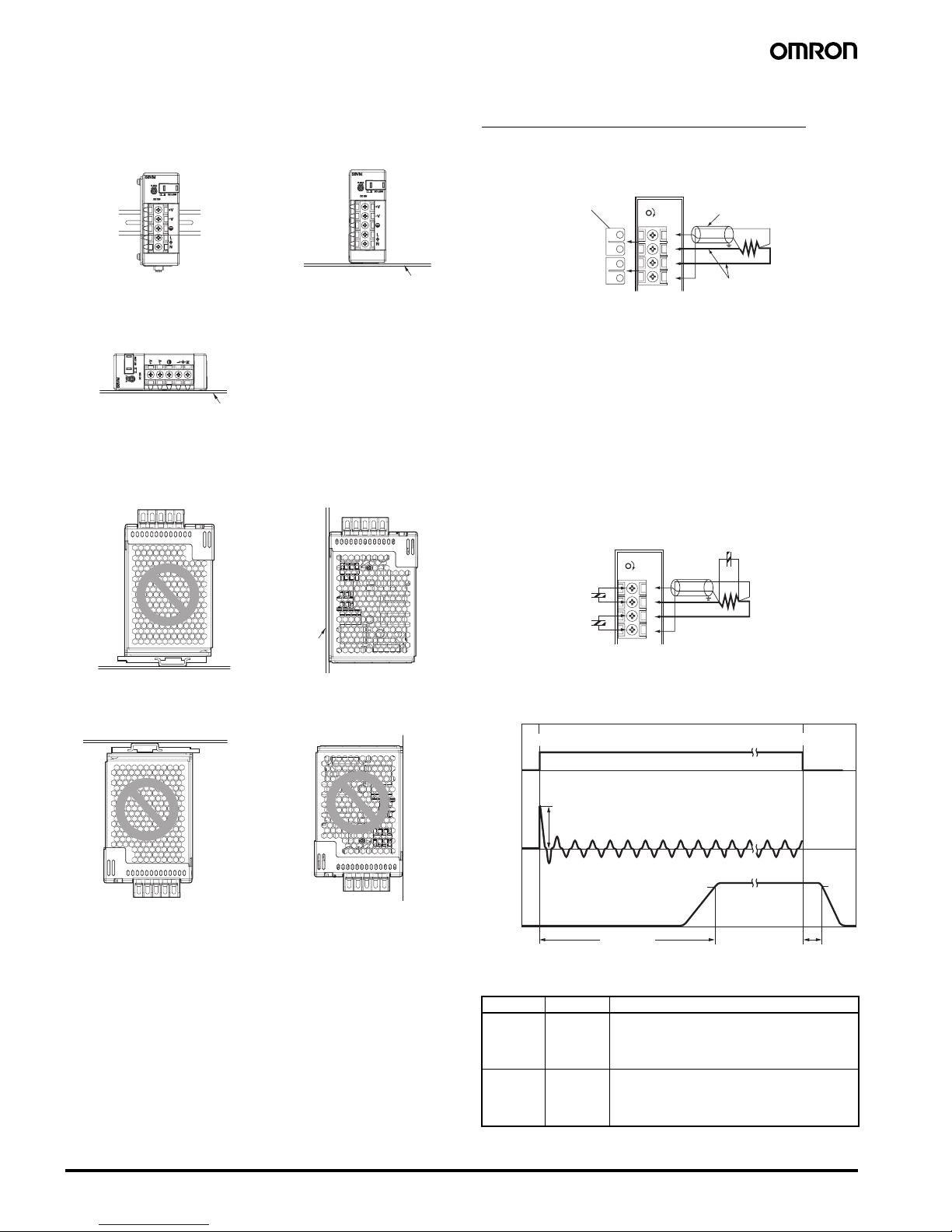
■Mounting
Note: 1. Improper mounting will interfere with heat dissipation and
may occasionally result in deterioration or damage of internal parts.
Use the Power Supply within the derating curve for the
mounting direction that is used.
2. Use the metal plate as the mounting panel (*1).
3. Install the Power Supply so that the air flow circulates
around the Power Supply, as the Power Supply is designed
to radiate heat by means of natural air flow.
4. Mounting screw tightening torque
(recommended value: M3 (0.49 N·m))
■Remote Sensing Function
(S8VM-100@@@@/150@@@@ only)
This function compensates a voltage drop on the load lines.
To use this function, connect after removing the two short bars of the
remote sensing terminal.
Note: 1. Use a 2-conductor shielded cable as a connection wire (*1).
2. Use as thick a wire as possible since high voltage drops on
the load lines (*2) may activate the overvoltage protection
function.
3. Use when the voltage drop is 0.3 V or lower.
4. When the +S and
−S terminals are opened with the shor t
bar removed, the overvoltage protection function is activated and the output voltage will be cut off.
5. If the load line is too long, use an electrolytic capacitor in the
following 3 locations:
1) Across the load terminals
2) Between the +S terminal and + terminal
3) Between the
−S terminal and − terminal
Select the capacity of the connected capacitor from between several tens to several hundreds of
µF as a guide,
and then determine the capacity when actually connecting
the capacitor between terminals as shown below.
■Inrush Current, Start Up Time,
Output Hold Time
■Reference Values
*1
*1
*1
Standard Mounting
(Bottom Mounting Models)
Horizontal Mounting
Correct
Correct
Correct
Face-up Mounting
(DIN Rail Mounting Bracket Models)
Face-up Mounting
Incorrect
Correct
Face-down Mounting
(DIN Rail Mounting Bracket Models)
Face-down Mounting
Incorrect
Incorrect
Standard Mounting
(DIN Rail Mounting Bracket Models)
Item Value Definition
Reliability
(MTBF)
135,000 hrs
min.
MTBF stands for Mean Time Between Failures, which
is calculated according to the probability of accidental
device failures, and indicates the reliability of a device.
Therefore, it does not necessarily represent the life of
the Power Supply.
Life
expectancy
10 yrs. min. The life expectancy indicates average operating hours
under the ambient temperature of 40
°C and a load rate
of 50%.
Normally this is determined by the life expectancy of
the built-in aluminum electrolytic capacitor.
DC ON
V.ADJ
+
S
+ V
−V
−S
*
1
*
2
Short bar
DC ON
V.ADJ
+
S
+ V
−V
−S
+
+
+
Start up time
Hold time
Inrush current on input application
90%
95%
Input ON
Input OFF
AC input
voltage
AC input
current
Output
voltage
Page 11
Switch Mode Power Supply S8VM 11
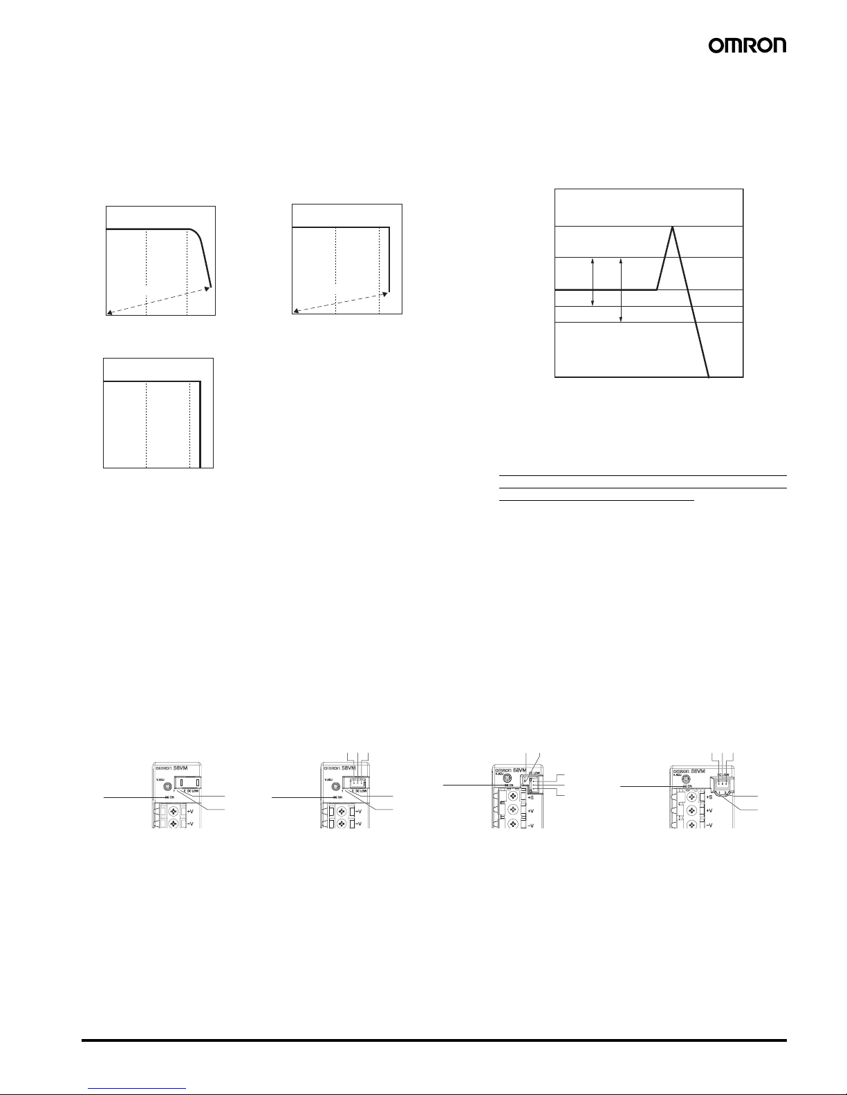
■Overload Protection
The Power Supply is provided with an overload protection function
that protects the Power Supply from possible damage by short-circuit
and overcurrent.
When the output current rises above 105% min. of the rated current,
the protection function is triggered, automatically decreasing the output voltage. When the output current falls within the rated range, the
overload protection function is automatically cleared.
The values shown in the above diagrams are for reference only.
Note: 1. Internal parts may occasionally deteriorate or be damaged
if a short-circuited or other overcurrent state continues during operation.
Eliminate the overcurrent state as soon as possible.
2. Internal parts may possibly be deteriorated or damaged if the
Power Supply is used for applications with frequent inrush current or overloading at the load end. Do not use the P ower Supply
for such applications.
■Overvoltage Protection
Consider the possibility of an overvoltage and design the system so
that the load will not be subjected to an excessive voltage even if the
feedback circuit in the Power Supply fails. When an excessive
voltage that is approximately 140% of the rated voltage or more is
output, the output voltage is shut OFF, preventing damage to the l oad
due to overvoltage. Reset the input power by turning it OFF for at
least three minutes and then turning it back ON again.
The values shown in the above diagram are for reference only.
*1 S8VM-@@@24A@/P@
*2 Except for S8VM-@@@24A@/P@
Note: 1. Do not turn ON the input power again until the cause of the
overvoltage has been removed.
2. The overvoltage protection function may be activated when
the output voltage adjuster (V.ADJ) is set to a value that exceeds +20% of the rated output voltage.
■Undervoltage Alarm Function (Indication and Output)
(Only S8VM-@@@24A@/P@)
If an output voltage drop is detected with an S8VM-@@@24A@/P@ with undervoltage alarm function, the DC LOW indicator will light to notify of an
output error. The transistor also sends an output externally to notify of the error (except for the S8VM-01524A@ and S8VM-03024A@).
Transistor Output: Sinking type: (NPN) (S8VM-@@@24A@)
Sourcing type: (PNP) (S8V M-@@@24P@)
30 VDC max., 50 mA max., Residual voltage when ON: 2 V or less, Leakage current when OFF: 0.1 mA or less
• Undervoltage Alarm Function 1 (DC LOW1)
Only a momentary voltage drop is detected. Detection voltage is automatically adjusted internally by detecting the output voltage (approx. 2.7 V
lower than the voltage output at an output voltage of 24.0 V).
During detection, the transistor is OFF (with no continuity across 8 and 10) and the LED (6: Yellow) lights. (The Undervoltage Alarm Function 1 is
used as a latch holding function.)
• Undervoltage Alarm Function 2 (DC LOW2)
Detection voltage is set to approx. 20.0 V (from 18.0 to 21.6 V).
During detection, the transistor is OFF (with no continuity across 9 and 10) and the LED (7: Red) lights.
Note: 1. This function monitors the voltage at the Power Supply output terminals.
To check actual voltage, measure voltage on the load side.
2. Gradual voltage drop is not detected by the Undervoltage Alarm Function 1 (DC LOW1).
3. Once undervoltage is detected by Undervoltage Alarm Function 1 (DC LOW1), the transistor turns OFF and status of the LED (6: Y ellow)
light is maintained. To reset the function, turn OFF the input power for 60 seconds or longer, and then turn it ON again.
4. If the output voltage remains at 15 V or lower for several seconds when using Undervoltage Alarm Function 1 (DC LOW 1), the output
hold status for detection may be reset.
Intermittent operation
Output current (%)
0 10050
Output voltage (V)
0 10050
Intermittent operation
Output current (%)
Output voltage (V)
0 10050
Output current (%)
Output voltage (V)
15W/30W
50W/100W/150W (5 V)
50W/100W/150W (12 V, 15 V, 24 V)
300W/600W/1,500W
Note: Refer to page 17.
Overvoltage protection
operating
Variable range
Rated output
voltage
+20%
−10%
−20%
0 V
Approx. 40%
*1 *2
Output voltage (V)
S8VM-01524A@
S8VM-03024A@
S8VM-05024A@/P@ S8VM-10024A@/P@ S8VM-15024A@/P@
4
6
7
4
6
7
8910
8
9
10
4
67
4
6
7
8
9
10
Page 12

12 Switch Mode Power Supply S8VM
■Probable Causes of Power Supply Errors and Troubleshooting Using
Undervoltage Alarm Function
Check the following information if the Undervoltage Alarm Function operates.
Contact your OMRON representative if the Power Supply does not function normally after checking.
The symbols in the table are as follows:
: Lit, : Not lit, : Flashing
Note: Flashing: The output voltage is unstable, causing the LED to repeatedly turn ON and OFF.
DC ON DC LOW1 DC LOW2
Output voltage Power Supply status diagnosis
LED D:
Green
LED F:
Yellow
Transistor
outputs
(H to J)
LED G:
Red
Transistor
outputs
(I to J)
1ONON→
Normal
(approx. 90% min.
of rated output
voltage)
Normal status
2OFFON
→
Normal
(approx. 90% min.
of rated output
voltage)
The output voltage has recovered to normal status
following a previous sudden voltage drop.
3ONOFF
→
Output drop
(approx. 90%
max. of rated
output voltage)
The output voltage has
dropped gradually and remains low.
4OFFOFF
→
Output drop
(approx. 90%
max. of rated
output voltage)
The output voltage remains low following a previous sudden voltage
drop.
5OFF
ON
OFF
→
Output drop
(approx. 80% of
rated output
voltage)
The output voltage remains low and is continuing to fluctuate following a
previous sudden voltage
drop.
6ON
ON
OFF
→
Output drop
(approx. 80% of
rated output
voltage)
The output voltage has
dropped gradually, remains low, and is continuing to fluctuate.
7OFFOFF
→ No output
No output voltage is being
output.
8
ON
OFF
ON
OFF
→ Unstable output
The output voltage is unstable.
24 V
24 V
24 V 24 V
⇔
24 V
⇔
24 V
⇔
⇔
24 V
Page 13

Switch Mode Power Supply S8VM 13
Probable cause of error Troubleshooting methods
--- --- 1
A momentary power failure has occurred in the
input.
Check that the output v oltage is normal and no problems ha ve occ urred in other de vices . No probl ems
will be caused by continuing to use the Power Supply as is. To clear DC LOW1 (LED display and tra nsistor output stat us), turn OFF the in put power , a nd wait at l east 60 s bef ore turning ON the input P ower
Supply aga i n.
2
A momentary overload has occurred. The load current has probably exceeded the rated curre nt. We suggest reduc ing the connected load
or replace the P ower Supply with one that has a higher capacity.
A momentary output voltage dro p has occurred
at startup due to the capacity of the capacitive
factors on the lo ad sid e or when the loa d is act ivated.
A large inrush current ha s pr obab ly flo wed to the load side at startup . W e s uggest replacing the P o wer
Supply with one that has a higher capacity.
The output voltage has returned to normal voltage following a rapid drop caused by using the
output voltage adjuster (V.ADJ).
Turn OFF the input power, and wait at least 60 s before turning ON the input power again to cle ar the
indicator status.
Deterioration due to age (when the Power Supply has been used for several years)
The internal parts of the Power Supply may have deteriorated due to age . We suggest replacing the
Power Supply. Also replace other Power Supplies that were purchased at the same time.
3
Overload (immediately following first use of the
Power Su pply or when increasing the load)
The load current has probably exceeded the rated current. Check the actual load current and Power
Supply capacity. Continued use in overload status may damage the Power Supply.
The output voltag e dr oppe d to - 10% or l owe r of
the rated voltage resulting from using the ou tput
voltage adjuster (V.ADJ)
Adjust the output voltage to the rated values using the output voltage adjuster (V.ADJ).
A sudden overload occurred and the Power
Supply remains in overload s tat us.
An error has probably occurred in the load device. Turn OFF the input power, and check whether any
errors have o ccurred in the load dev ice. Con tinued use in ov erload status ma y damage the P owe r Supply.
4
The output voltage remains low after a rapid
voltage drop caused b y using the out put volta ge
adjuster (V.ADJ).
Adjust the output voltage to the rated values using the output voltage adjuster (V.ADJ). To clear DC
LOW1 (LED display and transistor output status ), turn OFF the input power, and wait at least 60 s before turning ON the input power again.
The overload status continues to fluctuate following a sudden ov erload.
An error has probably occurred in the load device. Turn OFF the input power, and check whether any
errors have o ccurred in the load dev ice. Con tinued use in ov erload status ma y damage the P owe r Supply.
5
Deterioration due to age (after using the Power
Supply for several years)
The internal parts of the Po w er Supp ly may have det erior ated d ue t o age . Re place t he Power Supply.
Also replace other Power Supplies th at were purchased at the same time.
6
Overload (immediately following first use of the
Power Su pply or when increasing the load)
The load current has probably exceeded the rated current. Check the actual load current and Power
Supply capacity. Continued use in overload status may damage the Power Supply.
Power Supply interrupted or damaged. Check whether the input power is being applied correc tly. If there is no output even though the input
power is applied correctly, the internal circuit is probably damaged.
7
Overvoltage protection operation Turn OFF the in put power , and wait at le ast 3 min bef ore turning ON the in put power ag ain. If the s ame
status recurs, the internal circuit is probably damag ed.
The short bar has fallen of f, or the +S an d -S terminals are open.
Check whether the +S and -S terminals are open. I f so, t he overv oltage protection function is ac tivated .
Therefore, turn OFF the input power and wait at least th ree minutes before turning it ON aga in. (S8VM-
10024A@/P@ and S8VM-15024A@/P@ models only)
Output short-circuit Remove the cause of the output short-circuit.
Intermittent operation due to overload (S8VM-
01524A@/03024A@ only)
The load current has probably exceeded the rated current. Check the actual load current and Power
Supply capacity. Continued use in overload status may damage the Power Supply.
8
The Power Supply fails to start repeatedly due
to the capacity of the capacitive fa ctors on the
load side.
A large inrush current ha s pr obab ly flo wed to the load side at startup . W e s uggest replacing the P o wer
Supply with one that has a higher capacity.
The input turns ON and OFF repeatedly. Check whether the Po wer Supply’s input voltage is being applied correctly.
The status repeatedly swit ches between normal
operation and output short-circ uit.
An error has probably occurred in the load device. Turn OFF the input power, and check whether any
errors have occur r e d i n th e load device.
Page 14

14 Switch Mode Power Supply S8VM
Construction and Nomenclature (300-W, 600-W, 1,500-W Models)
■Nomenclature
300-W Models
S8VM-300@@C
600-W Models
S8VM-600@@C
1,500-W Model
S8VM-15224C
■Output Color Label
This color label identifies the output voltage by color.
Note: A 300-W model is shown above. The label is in a different place
on 600-W models and 1,500-W model.
Note: 1. The fuse is located on the (L) side. It is NOT user-replace-
able.
2. Protective earthing connection is the panel mounting hole of
the metal case. (A protective earthing connection stipulated
in safety standards is used. Connect the ground completely).
Ground terminal: M4 (Depth: 6 mm max.)/Ground wire:
AWG 18
3. The enclosed standard connector for signal I/O is mounted
to CN when S8VM is shipped. The enclosed signal I/O connector shorts between 1 and 2, between 3 and 4, and between 7 and 8.
Do not connect a load to the output voltage monitor terminals (+V, -V).
Color label identifying output voltage
Green: 5 V
Blue: 12 V
Yellow: 15 V
White: 24 V
No. Name Function
1 AC input terminal (L), (N) Connect the input lines to these terminals.
(See note 1.)
2 PE terminal: Protective earth-
ing terminal
(S8VM-300@@C/S8VM600@@C)
FG terminal: Frame ground terminal (S8VM-15224C)
Connect the ground line to this terminal.
(See note 2.)
3 DC output terminals (
−V), (+V) Connect the load lines to these terminals.
4 Output indicator (DC ON:
Green)
Lights (green) while a direct current (DC)
output is ON.
5 Output voltage adjuster
(V.ADJ)
Use to adjust the voltage.
6 Power failure alarm indicator
(PF: Red)
Lights when the output voltage decreases,
the fan stops, and the system is on standby using the remote control function.
7 Signal I/O connector (See note
3.)
1: DC output monitor pin (+V)
2: Remote sensing pin (+S)
3: DC output monitor pin (-V)
4: Remote sensing pin (-S)
5: Current balance pin (CB)
6: Signal ground pin for current balance
(CBG)
7: Remote control pin (+RC)
8: Remote control pin (-RC)
9: No connect
10: No connect
11: P o wer failure alarm output pin (PF-C)
(collector)
12: Power failur e alarm output pin (PF-E)
(emitter)
1
3
5
7
9
11
2
4
6
8
10
12
CN
Page 15

Switch Mode Power Supply S8VM 15
Engineering Data (300-W, 600-W, 1,500-W Models)
■Derating Curve
300W/600W/1,500W
Note: 1. Internal parts may occasionally be deteriorated or dam-
aged. Do not use the Pow er Supply in areas outside the derating curves (i.e., the area shown by shading A in the
above graph).
2. When mounting two or more Power Supplies side-by-side,
allow at least 20 mm spacing between them. Alwa ys provide
at least 50 mm of mounting space for the surface with the
fan mounted. Be sure to provide at least 50 mm (S8VM300@@C/600@@C) or 100 mm (S8VM-15224C) of mounting space on the opposite side of the surface with the fan
mounted.
3. When using the 1,500-W model for a long period of time at
an input voltage of 90 VAC or lower, reduce the load to 80%
or less of the above derating curve.
4. The ambient temperature is specified at a location 50 mm in
front of the center of the Power Supply's front panel.
■Mounting
Standard Mounting
Horizontal Mounting
Upside-down Mounting (S8VM-15224C Only)
Side Mounting
Note: 1. The internal part s may occasionally deteriorate or be bro-
ken due to adverse heat dissipation depending on the
mounting status. Do not use the Power Supply in any
mounting direction other than those specified.
2. Use the metal plate as the mounting panel (*1).
3. To ensure sufficient cooling, do not cover the air holes locat-
ed on the side the fan is mounted and the opposite side.
4. Mounting screw tightening torque (recommended value: M4
(1.27 N·m))
The screws must not protrude more than 6 mm inside the
Power Supply.
■Remote Sensing Function
This function is used to compensate for voltage drops on the load
lines. Connect the
+S pin (pin 2 on CN) to the positive load terminal
and the
−S pin (pin 4 on CN) to the negative load terminal to enable
remote sensing. When not using the remote sensing function, use
the standard connector. The
+S and +V pins (pin 1 on CN) and the
−S and −V pins (pin 3 on CN) will be connected.
Note: 1. Use 2-conductor shielded cable as connection wire (* 1).
2. Use as thick a wire as possible since high voltage drops on
the load lines (* 2) may activate the overvoltage protection
function.
3. Use when the voltage drop is 0.3 V or lower.
4. If the sensing line is too long, it is necessary to put an elec-
trolytic capacitor across the load terminals. The electrolytic
capacitor may generate heat due to the ripple current, depending on connected load. Therefore, the electrolytic capacitor must have a ripple current allowance higher than the
output ripple current.
5. The stability and accuracy of the output will deteriorate if the
+S or −S pins are open. Always connect the +S and −S pins.
6. Remove the standard supplied connector and prepare a
connector separately.
−20 −10 0 10 20 30 40 50 60 70 80
120
100
80
60
40
20
0
Load ratio (%)
Ambient temperature (˚C)
*1 *1 *1
300 W
600 W
1,500 W
Correct CorrectCorrect
600 W
*1 *1 *1
300 W 1,500 W
Correct CorrectCorrect
*1
1,500 W
Correct
300 W
600 W
1,500 W
Incorrect IncorrectIncorrect
+V
*2
+
−V
*1
−V −S
S8VM
CN
+V +S
Page 16

16 Switch Mode Power Supply S8VM
■Remote Control Function
This function turns outputs ON and OFF using an external signal
while input voltage is applied, using the +RC pin (pin 7 on CN) and
the -RC pin (pin 8 on CN). Connect a switch or transistor to the +RC
and -RC pins to use the remote control function. When not using this
function, the +RC and -RC pins are shorted by using the standard
supplied connector.
Maximum input voltage: 12 V max.
Maximum allowable reverse voltage:
−1 V max.
Sink Current: 3.5 mA
Note: 1. Use 2-conductor shielded cable or twisted-pair cable as
connection wire.
2. The remote control circuit is isolated from the input and output circuits of the power supply.
3. Remove the standard supplied connector and prepare a
connector separately.
■Power Failure Alarm Function
The power failure alarm indicator will light red to indicate an output
voltage error if overload, overvoltage, or overheat protection is activated, if a drop in the input voltage causes the output voltage to drop,
if the built-in fan motor stops, and during remote control standby. The
alarm is also output externally by a transistor.
Transistor output: 30 VDC max., 50 mA max.
Residual voltage when ON: 2 V max.
Leakage current when OFF: 0.1 mA max.
Alarm detection voltage: Approx. 80% of output voltage setting
During detection, the transistor is OFF (with no continuity across pins
11 and 12 on CN), and the LED (red) lights.
Note: 1. This function monitors the voltage at the Power Supply out-
put terminals. T o chec k actual v oltage, measure the voltage
on the load side.
2. Outputs are forced OFF if the built-in fan motor stops
(S8VM-15224C only).
3. Remove the standard supplied connector and prepare a
connector separately.
■Inrush Current, Start Up Time,
Output Hold Time
■Input Current Waveform When
Input Is Turned O N
(The following examples show typical waveforms.)
S8VM-300@@C
100 VAC, Load ratio: 100%
200 VAC, Load ratio: 100%
+RC Level for −RC Output Built-in Fan Motor
Short or L (0 to 0.8 V) ON Rotate
Open or H (2.4 to 12 V) OFF Stop
T
R
SW
+RC
−RC
S8VM
CN
PF-C
PF-E
S8VM
CN
Vce max.: 30 VDC
Ic max.: 50 mA
Start up time
Hold time
Inrush current on input application
90%
95%
Input ON
Input OFF
AC input
voltage
AC input
current
Output
voltage
100 ms
AC input
current
(10 A/DIV)
AC input
voltage
Output
voltage
100 ms
AC input
current
(10 A/DIV)
AC input
voltage
Output
voltage
Page 17

Switch Mode Power Supply S8VM 17
S8VM-600@@C
100 VAC, Load ratio: 100%
200 VAC, Load ratio: 100%
S8VM-15224C
100 VAC, Load ratio: 100%
200 VAC, Load ratio: 100%
■Reference Values
■Overload Protection
The Power Supply is automatically protected from short-circuit or
overcurrent damage by the overload protection function. Overload
protection is activated if the output current rises above 105% of the
rated current.
S8VM-300@@C/600@@C
When the output current returns within the rated range, overload protection is automatically cleared.
S8VM-15224C
Outputs are interrupted if an overload continues for 5 seconds or
more. To reset the Power Supply, leave input power OFF for more
than 3 minutes and then turn it ON again. Alternatively, turn OFF and
ON the remote control signal.
The values shown in the above diagrams are for reference only.
Note: 1. If the Power Supply has been short-circuited or supplied
with an overcurrent longer than 30 seconds, the internal
parts of the Power Supply may occasionally be deteriorated
or damaged.
2. The internal parts may possibly be deteriorated or damaged. Do not use the Power Supply for applications where
the load causes frequent inrush current and overload.
100 ms
AC input
current
(10 A/DIV)
AC input
voltage
Output
voltage
100 ms
AC input
current
(10 A/DIV)
AC input
voltage
Output
voltage
100 ms
AC input
current
(25 A/DIV)
AC input
voltage
Output
voltage
100 ms
AC input
current
(10 A/DIV)
AC input
voltage
Output
voltage
Item Value Definition
Reliability
(MTBF)
300 W:
135,000 hrs
600 W:
120,000 hrs
1,500 W:
100,000 hrs
MTBF stands for Mean Time Between Failures, which
is calculated according to the probability of accidental
device failures , a nd indicates the relia bility of a device.
Therefore, it does not necessarily represent the life of
the Power Supply.
Life
expectancy
10 yrs. min. The life expectancy indicates average operating hours
under the ambient temperature of 40
°C and a load rate
of 50%.
Normally this is determined by the life expectancy of
the built-in aluminum electrolytic capacitor.
0 10050
Output current (%)
Intermittent operation
Output voltage (V)
300W/600W (5 V) 300W600W/1,500W (12 V, 15 V, 24 V)
0 10050
Output current (%)
Output voltage (V)
Page 18

18 Switch Mode Power Supply S8VM
■Overvoltage Protection
Consider the possibility of an overvoltage and design the system so
that the load will not be subjected to an excessive voltage even if the
feedback circuit in the Power Supply fails. When an excessive voltage that is approximately 140% of the rated voltage or more is output, the output voltage is shut OFF, preventing damage to the load
due to overvoltage. Reset the input power by turning it OFF for at
least three minutes and then turning it back ON again. Alternatively,
turn OFF and ON the remote control signal.
The values shown in the above diagram are for reference only.
Note: 1. Do not turn ON the input power again until the cause of the
overvoltage has been removed.
2. The overvoltage protection function may be activated when
the output voltage adjuster (V.ADJ) is set to a value that exceeds +20% of the rated output voltage.
■Overheat Protection
The overheat protection circuit will operate and outputs will be shut
OFF to protect the Power Supply if the ambient temperature rises,
the fan stops, or other errors cause the Power Supply's internal temperature to rise. To reset the Power Supply, leave the input power
OFF long enough for the Power Supply to cool sufficiently and then
turn it ON again. Alternatively turn OFF the remote control signal
long enough to cool sufficiently and then turn it ON again.
■Peak Output Current
(S8VM-30024C/6 002 4C /1 52 24C Only)
The peak current must satisfy the following conditions. Reduce the
peak current according to the load rate of the derating curve.
Approx. 40%
Output voltage (V)
+20%
−20%
0 V
Variable range
Rated output
voltage
Overvoltage protection
operating
Ip
Ip:
Irms:
lav:
la:
D:
τ:
T:
Peak current (A)
Effective current (A)
Rated current (A)
Continuous load current (A)
Duty
Peak current pulse width (s)
C
y
cle (s
)
Ia
Irms
0 A
T
τ
D=
T
τ
Irms= lp2 × D + la2× (1−D) ≤ lav
Input voltage range: 180 to 240 VAC
Peak current pulse width: 10 s max.
Duty: 35% max.
Peak current value: Within the rated peak current
Effective current: Within the rated current
Page 19

Switch Mode Power Supply S8VM 19
Dimensions
Note: All units are in millimeters unless otherwise indicated.
■Bottom Mount ing Models (15-W, 30-W, 50-W, 100-W, 150-W Models)
62±0.5
67±0.3
68±0.5
15.5±0.5
8.5±0.5
8.5±0.5
8.5±0.5
84.5
84.5
33.5
Two, M3 (depth: 8 max.)
Two, M3 (depth: 8 max.)
13.6 max.
8.5±0.5
8.5±0.5
Two, M3 (depth: 8 max.)
17.6 max.
8.5±0.5
27
81.5
80.5
62±0.5
68±0.5
15.5±0.5
67±0.3
Two, M3 (depth: 8 max.)
S8VM-015@@
S8VM-015@@C
S8VM-01524A
Note: The image is the S8VM-01524 Model.
Mounting Holes
Bottom View
Side
Mounting
Bottom
Mounting
62±0.5
68±0.5
Two, 4 dia.
67±0.3
Two, 4 dia.
Note: The image is the S8VM-01524A Model.
84.5
33.5
13.6 max.
99.5
8.5±0.5
68±0.5
77±0.5
82±0.3
8.5±0.5
15.5±0.5
8.5±0.5
Two, M3 (depth: 8 max.)
Two, M3 (depth: 8 max.)
8.5±0.5
8.5±0.5
27
95.5
82.5
68±0.5
8.5±0.5
15.5±0.5
77±0.5
82±0.3
17.6 max.
Two, M3 (depth: 8 max.)
Two, M3 (depth: 8 max.)
S8VM-030@@
S8VM-030@@C
S8VM-03024A
Note: The image is the S8VM-03024 Model.
Mounting Holes
Bottom View
Side
Mounting
Bottom
Mounting
77±0.5
68±0.5
Two, 4 dia.
82±0.3
Two, 4 dia.
Note: The image is the S8VM-03024A Model.
Page 20

20 Switch Mode Power Supply S8VM
68±0.5
8.5±0.5
8.5±0.5
15±0.2
83±0.5
32.5±0.5
8±0.2
23.5±0.3
120.5
27
82.5
97±0.5
17.6 max.
Three, M3 (depth: 4 max.)
Two, M3 (depth: 8 max.)
8.5±0.5
97±0.5
15±0.2
8±0.2
23.5±0.3
124.5
84.5
83±0.5
32.5±0.5
68±0.5
8.5±0.5
33.5
13.6 max.
Three, M3 (depth: 4 max.)
Two, M3 (depth: 8 max.)
S8VM-050@@
S8VM-050@@C
S8VM-05024A
S8VM-05024P
Note: The image is the S8VM-05024 Model.
Mounting Holes
Bottom View
Side
Mounting
Bottom
Mounting
97±0.5
68±0.5
Two, 4 dia.
83±0.5
8±0.2
15±0.2
Three, 4 dia.
Note: The image is the S8VM-05024A Model.
82.5
17.6 max.
160.5
8.5±0.5
68±0.5
135±0.5
120±0.5
8.5±0.5
15±0.2
7.5±0.2
25±0.2
30±0.5
28.5
Three, M3
(depth: 4 max.)
Two, M3 (depth: 8 max.)
84.5
35
13.6 max.
164.5
8.5±0.5
68±0.5
135±0.5
120±0.5
8.5±0.5
15±0.2
7.5±0.2
25±0.2
30±0.5
Three, M3 (depth: 4 max.)
Two, M3 (depth: 8 max.)
S8VM-100@@
S8VM-100@@C
S8VM-10024A
S8VM-10024P
Note: The image is the S8VM-10024 Model.
Mounting Holes
Bottom View
Side
Mounting
Bottom
Mounting
68±0.5
135±0.5
Two, 4 dia.
120±0.5
7.5±0.2
15±0.2
Three, 4 dia.
Note: The image is the S8VM-10024A Model.
Page 21

Switch Mode Power Supply S8VM 21
13.6 max.
44
84.5
164.5
120±0.5
25±0.5
135±0.5
8.5±0.5
8.5±0.5
68±0.5
7.5±0.2
15±0.2
26.5±0.2
Three, M3 (depth: 4 max.)
Two, M3 (depth: 8 max.)
17.6 max.
160.5
135±0.5
8.5±0.5
8.5±0.5
68±0.5
37.5
82.5
25±0.5
7.5±0.2
120±0.5
15±0.2
26.5±0.2
Three, M3 (depth: 4 max.)
Two, M3 (depth: 8 max.)
S8VM-150@@
S8VM-150@@C
S8VM-15024A
S8VM-15024P
Note: The image is the S8VM-15024 Model.
Note:The image is the S8VM-15024A Model.
Mounting Holes
Bottom View
Side
Mounting
Bottom
Mounting
68±0.5
135±0.5
Two, 4 dia.
120±0.5
7.5±0.2
15±0.2
Three, 4 dia.
Page 22

22 Switch Mode Power Supply S8VM
■DIN Rail Mounting Brac ke t Mo de ls (15-W, 30-W, 50-W, 100- W, 15 0- W Mode ls)
17.6 max.
3.5 max.
14
5.4 (Sliding: 9 max.)
80.5
81.5
90.4
33
84.5
46.2
84.5
94.4
15 max.
35.1
3.5 max.
14
5.4 (Sliding: 9 max.)
S8VM-015@@D
S8VM-015@@CD
S8VM-01524AD
Note: The image is the S8VM-01524D Model.
Note: The image is the S8VM-01524AD Model.
33
17.6 max.
3.5 max.
14
82
5.4 (Sliding: 9 max.)
105.4
95.5
99.5
15 max.
14
109.4
46.2
84.5
3.5 max.
35.1
5.4 (Sliding: 9 max.)
S8VM-030@@D
S8VM-030@@CD
S8VM-03024AD
Note: The image is the S8VM-03024D Model.
Note: The image is the S8VM-03024AD Model.
Page 23

Switch Mode Power Supply S8VM 23
33
17.6 max.
3.5 max.
14
82.5
5.4 (Sliding: 9 max.)
130.4
120.5
15 max.
124.5
14
84.5
134.4
46.2
35.1
5.4 (Sliding: 9 max.)
3.5 max.
S8VM-050@@D
S8VM-050@@CD
S8VM-05024AD
S8VM-05024PD
Note: The image is the S8VM-05024D Model.
Note: The image is the S8VM-05024AD Model.
33
17.6 max.
3.5 max.
14
82.5
5.4 (Sliding: 9 max.)
170.4
160.5
36.6
14
164.5
46.2
84.5
174.4
15 max.
3.5 max.
5.4
(Sliding: 9 max.)
S8VM-100@@D
S8VM-100@@CD
S8VM-10024AD
S8VM-10024PD
Note: The image is the S8VM-10024D Model.
Note: The image is the S8VM-10024AD Model.
Page 24

24 Switch Mode Power Supply S8VM
17.6 max.
3.5 max.
14
5.4 (Sliding: 9 max.)
170.4
160.5
82.5
39.1
15 max.
164.5
14
174.4
46.2
84.5
5.4 (Sliding: 9 max.)
45.6
3.5 max.
S8VM-150@@D
S8VM-150@@CD
S8VM-15024AD
S8VM-15024PD
Note: The image is the S8VM-15024D Model.
Note: The image is the S8VM-15024AD Model.
Page 25

Switch Mode Power Supply S8VM 25
■Bottom Mount ing Models (300-W, 600-W, 1,500-W Models)
Mounting Holes
Bottom View
Standard
Mounting
Horizontal
Mounting
Four, 4.5 dia.
60±0.5
110±0.5
Four, 4.5 dia.
40±0.5
120±0.5
188 max.
Four, M4 (depth: 6 max.)
Four, M4 (depth: 6 max.
)
105±0.5
62.5
25
22 max.
120±0.5
25
22 max.
83.5
60±0.5
11
10.5
40±0.5
120±0.5
40±0.5
192 max.
26 max.
25
110±0.5 46 max.
101.8
83.8
21
20
60±0.5
Four, M4 (depth: 6 max.
)
Four, M4 (depth: 6 max.)
260±0.5
46 max.
10
260±0.5
10
M8 (See note.)
126.5
82
60±0.5
11
7.25
112±0.5
327 max.
Four, M4 (depth: 6 max.)
Four, M4
(dep
th: 6 max.
)
S8VM-300@@C
Note: The image is the S8VM-60024C Model.
Note: M8 bolts and nuts for the output terminals are not included.
Note: The image is the S8VM-30024C Model.
S8VM-600@@C
S8VM-15224C
Mounting Holes
Bottom View
Standard
Mounting
Horizontal
Mounting
Four, 4.5 dia.
40±0.5
120±0.5
Four, 4.5 dia.
60±0.5
105±0.5
Mounting Holes
Bottom View
Standard
Mounting
Horizontal
Mounting
Four, 4.5 dia.
112±0.5
260±0.5
Four, 4.5 dia.
60±0.5
260±0.5
Page 26

26 Switch Mode Power Supply S8VM
■Mounting Brackets
Mounting Bracket A (Bottom Mounting for 15-, 30-, and 50-W Models)
Mounting Bracket B (Bottom Mounting for 100-, and 150-W Models)
Name Model
Mounting Bracket A (bottom mounting for 15-, 30-, and 50-W models) S82Y-VM10B
Mounting Bracket B (bottom mounting for 100- and 150-W models) S82Y-VM20B
Mounting Bracket C (front mounting for 15-, 30-, 50-, 100-, and 150-W models) S82Y-VM10F
Mounting Bracket D (bottom mounting for 300-W models) S82Y-VM30B
Mounting Bracket E (horizontal bottom mounting for 300-W models) S82Y-VM30S
Mounting Bracket F (front mounting for 300-W models) S82Y-VM30F
Mounting Bracket G (DIN Rai l mounting for 300-W models ) S82Y-VM30D
Mounting Bracket H (bottom mounting for 600-W models) S82Y-VM60B
Mounting Bracket I (horizontal bottom mounting for 600-W models) S82Y-VM60S
Mounting Bracket J (front mounting for 600-W models) S82Y-VM60F
Mounting Bracket K (DIN Rail mounting for 600-W models) S82Y-VM60D
150
35
20±0.5
7.5
4
R2
R2
4 dia.
140±0.5
5
t = 2.
3
5
Three, M3.5
c
a
c
b
a, c
b
a = Mounting holes for 15-W models
b = Mounting holes for 30-W models
c = Mounting holes for 50-W models
A
B
B
B
A
A
S82Y-VM10B
Using the Mounting Bracket
Screws Used
A: Accessories
(Use the enclosed screws in two
places for 15-W a nd 30-W mo dels
and in three places for 50-W m odels.)
B: M3 or M3.5
(three places)
Mounting screw tightening torque
(recommended): 0.49 N·m
a
b
a
b
a
b
40
20±0.5
4
R2
4 dia.
5
192
15±0.2
182±0.5
Three, M3.5
t = 2.3
a = Mounting holes for 100-W models
b = Mounting holes for 150-W models
A
B
B
B
A
A
S82Y-VM20B
Using the Mounting Bracket
Screws Used
A: Accessories
(Use the enclosed screws in three
places.)
B: M3 or M3.5
(three places)
Mounting screw tightening torque (recommended): 0.49 N·m
Page 27

Switch Mode Power Supply S8VM 27
Mounting Bracket C (Front Mounting for 15-, 30- 50-, 100-, and 150-W Models)
Mounting Bracket D (Bottom Mounting for 300-W Models)
33
15
4
R2
5
8.3
a, b
d, e
d, e
a, b, c, d, e
c
13.4
4 dia.
58
80
97±0.5105
t = 1.6
a = Mounting holes for 15-W models
b = Mounting holes for 30-W models
c = Mounting holes for 50-W models
d = Mounting holes for 100-W model
s
e = Mounting holes for 150-W model
s
A
B
B
B
A
A
S82Y-VM10F
Using the Mounting Bracket
Screws Used
A: Accessories
(Use the enclosed screws in two places for 15-W, 30-W and 50W models and in three places for 100-W and 150-W models.)
B: M3 or M3.5
(three places)
Mounting screw tightening torque (recommended): 0.49 N·m
5 195
60
48
Three, 4.5 dia.
B
A
A
A
A
B
B
S82Y-VM30B
Using the Mounting Bracket
Screws Used
A: Accessories
(Use the enclosed screws in four places.)
B: M4
(three places)
Mounting screw tightening torque (recommended): 1.27 N·m
Page 28

28 Switch Mode Power Supply S8VM
Mounting Bracket E (Horizontal Bottom Mounting for 300-W Models)
Mounting Bracket F (Front Mounting for 300-W Models)
6
202
8
215
52
84
16
Three, 4.5 dia.
B
A
A
A
A
B
B
S82Y-VM30S
Using the Mounting Bracket
Screws Used
A: Accessories
(Use the enclosed screws in four places.)
B: M4
(three places)
Mounting screw tightening torque (recommended): 1.27 N·m
A
A
A
A
B
B
B
60
4.5
Two, 4.5 dia.
48
67
13.5
102.3 105
243 max.
215.3
5
S
82Y-VM30F
Using the Mounting Bracket
Screws Used
A: Accessories
(Use the enclosed screws in four places.)
B: M4
(three places)
Mounting screw tightening torque (recommended): 1.27 N·m
Page 29

Switch Mode Power Supply S8VM 29
Mounting Bracket G (DIN Rail Mounting for 300-W Models)
Mounting Bracket H (Bottom Mounting for 600-W Models)
Mounting Bracket I (Horizontal Bottom Mounting for 600-W Models)
6.4
60
102.3
67
9.5
243 max.
215.3
A
A
A
A
82Y-VM30D
Using the Mounting Bracket
Screws Used
A: Accessories
(Use the enclosed screws in
four places.)
Mounting screw tightening torque
(recommended): 1.27 N·m
B
A
A
A
B
B
6
202
8
215
100
72
Three, 4.5 dia.
S82Y-VM60B
Using the Mounting Bracket
Screws Used
A: Accessories
(Use the enclosed
screws in four places.)
B: M4
(three places)
Mounting screw tightening
torque (recommended):
1.27 N·m
6
202
8
215
84
52
16
Three, 4.5 dia.
B
A
A
A
A
B
B
S82Y-VM60S
Using the Mounting Bracket
Screws Used
A: Accessories
(Use the enclosed
screws in four places.)
B: M4
(three places)
Mounting screw tightening
torque (recommended):
1.27 N·m
Page 30

30 Switch Mode Power Supply S8VM
Mounting Bracket J (Front Mounting for 600-W Models)
Mounting Bracket K (DIN Rail Mounting for 600-W Models)
Two, 4.5 dia.
102.3
82
98
105
13.5
4.5
5
105
257 max.
222.3
A
A
A
A
B
B
B
S82Y-VM60F
Using the Mounting Bracket
Screws Used
A: Accessories
(Use the enclosed screws in
four places.)
B: M4
(three places)
Mounting screw tightening torque
(recommended): 1.27 N·m
A
A
A
A
S82Y-VM60D
Using the Mounting Bracket
Screws Used
A: Accessories
(Use the enclosed screws in
four places.)
Mounting screw tightening to rque
(recommended): 1.27 N·m
257 max.
222.3
9.5
6.4
102.3
98
105
Page 31

Switch Mode Power Supply S8VM 31
■Other Items Sold Separately
Undervoltage Alarm Output Wiring Cable
■DIN Rail (Order Separately)
Note: All units are in millimeters unless otherwise indicated.
Mounting Rail (Material: Aluminum)
Mounting Rail (Material: Aluminum)
Name Model
Undervoltage Alarm Output Wiring Cable S82Y-VM10H
Terminal and Housing S82Y-VM30C
Replacement Fan Unit for 300-W Models S82Y-VM30FAN
Replacement Fan Unit for 600-W Models S82Y-VM60FAN
Replacement Fan Unit for a 1,500-W Model S82Y-VM15FAN
3,000±50
: AWG24
XHP-3 (Manufactured by JST)
to
:
S82Y-VM60D (for S8VM-05024A@/05024P@/10024A@/10024P@/15024A@/15024P@ Only)
Using the Undervoltage Alarm
Output Wiring Cable
1,000 (500) *
15(5) *
*Values in parentheses
are for the PFP-50N.
PFP-100N
PFP-50N
4.5
15 25 25
10 10
25 25
35
±
0.3
7.3
±
0.15
27
±
0.15
1
PFP-100N2
4.5
15 25 25
10 10
1,000
25 25 15
11.5
29.2242735
±
0.3
16
Page 32

32 Switch Mode Power Supply S8VM
Safety Precautions
■Precautions for Safe Use
Mounting
Ensure sufficient heat dissipation when installing the Power Supply
to increase its long-term reliability.
Use the metal plate as the mounting panel.
When cutting out holes for mounting, make sure that cuttings do not
enter the interior of the Power Supply.
When mounting two or more Power Supplies side-by-side, allow at
least 20 mm spacing between them, as shown in the illustrations
below.
15/30/50/100/150-W Models
Natural cooling is used, so mount the Power Supply so that there is
airflow around it.
Improper mounting will interfere with heat dissipation and may occasionally result in deterioration or damage of internal parts. Use the
Power Supply within the derating curve for the mounting direction
that is used.
The internal parts may possibly be damaged if mounting screws are
over inserted. Refer to Dimensions on page 19 to 21 for maximum
depth of insertion inside the Power Supply.
Several Power Supplies cannot be connected. (Only S8VM100@@@@/150@@@@) Keep the Power Supply as far away from
heating elements as possible when installing. As a reference value,
allow at least 50 mm spacing on the right and left sides. If only 20
mm spacing is allowed, use the Power Supply at a load ratio of 80%
or less.
300/600/1,500-W Models
A forced-air cooling method with a fan is used. To ensure sufficient
cooling, do not cover the air holes located on the side the fan is
mounted and the opposite side.
Improper mounting will interfere with heat dissipation and may occasionally result in deterioration or damage of internal parts. Do not
use the Power Supply in any mounting direction other than those
specified.
The internal parts may possibly be damaged if mounting screws are
over inserted. The screws must not protrude more t han 6 mm inside
the Power Supply.
Note: 1. Convection of air
2. 50 mm or more
3. (S8VM-300@@C/600@@C): 50 mm or more
(S8VM-15224C): 100 mm or more
4. 20 mm or more
5. Use a metal plate as the mounting panel.
Wiring
Connect the ground completely. A protective earthing connection
stipulated in safety standards is used. Electric shock or malfunction
may occur if the ground is not connected completely.
Minor fire may possibly occur. Ensure that input and out put terminals
are wired correctly.
Do not apply more than 100 N force to the terminal block when
tightening it.
Be sure to remove the sheet covering the Power Supply for
machining before power-ON so that it does not interfere with heat
dissipation.
Use the following material for the wires to be connected to the S8VM
to prevent smoking or ignition caused by abnormal loads.
Over heating or fire can result from inadequately sized wiring
materials when problems occur at the load. As a general rule, always
select wire sizes suitable for at least 1.6 times the rated current.
Refer to the wiring manufacturer's recommended allowable current
and voltage drop specifications for information when selecting wiring
materials.
Minor electric shock, fire, or Product failure may
occasionally occur. Do not disassemble, modify, or repair
the Product or touch the interior of the Product.
Minor burns may occasionally occur. Do not touch the
Product while power is being supplied or immediately
after power is turned OFF.
Fire may occasionally occur. Tighten terminal screws to
the specified torque.
15-, 30-, 50-, 100-, and 150-W models (1.6 N·m)
300-, 600-, and 1,500-W models (M4; 1.27 N·m, M5; 2.50
N·m, M8 bolts and nuts; 10.8 N·m)
Minor injury due to electric shock may occasionally occur.
Do not touch the terminals while power is being supplied.
Minor electric shock, fire, or Product failure may
occasionally occur. Do not allow any pieces of metal or
conductors or any clippings or cuttings resulting from
installation work to enter the Product.
Standard Mounting
(DIN Rail Mounting Bracket Models)
Standard Mounting
(Front Mounting Models)
Horizontal Mounting Face-up Mounting
!CAUTION
(
See note 2.
)
(See note 1.)
(See note 1.)
(
See note 2.
)
(See note 3.)
(See
note 1.)
(See
note 1.)
(See note 1.)
(See note 2.)
(See
note 1.)
(See note 3.)
Note: 1. Convection of air
2. 20 mm or more
3. Use a metal plate as the
mounting panel.
(See note 1.)
(See note 3.)
S8VM-100@@@@/S8VM-150@@@@
Incorrect Incorrect
(See note 2.)
S8VM
(See
note
1.)
(See
note
1.)
(See note 3.)
(See note 5.)
(See note 4.)
Page 33

Switch Mode Power Supply S8VM 33
Recommended Wire Sizes
The current rating for the output terminals on the S8VM-300@@C is
40 A per terminal. The current rating for the output terminals on the
S8VM-600@@C is 60 A per terminal. Use two ter minals together if a
current exceeding the terminal rating is used.
Use min. 60°C or 60/75°C wire.
Use copper conductors only.
Undervoltage Alarm Output Connector
Harness Manufacture Method
The following products are provided with the S8VM-05024A@/P@,
S8VM-10024A@/P@ and S8VM-15024A@/P@ for the undervoltage
alarm transistor output wiring.
Be sure to prepare the connector according to the following instructions to ensure correct wiring. For details, refer to the JST catalog.
• Use a wire size of AWG28 to A WG22.
• The guideline for the length of sheath to be stripped from the wire is
2.1 to 2.6 mm.
• Use either a YC or YRS Crimping Tool (manufactured by JST) to
crimp the terminal and wire.
• Be sure to inser t the crimped terminal wires into the housing fully
until a click is heard. Also, make sure that the wires attached to the
housing are securely locked in place.
Signal I/O Connector Harness
Manufacture Method
The S8VM-300@@C/600@@C/15224C are using PHD connector
(manufactured by JST).
Be sure to prepare the connector according to the following instructions to ensure correct wiring. For details, refer to the JST catalog.
• Use a wire size of AWG26 to A WG22.
• The guideline for the length of sheath to be stripped from the wire is
2.3 mm.
• Use a YC Crimping Tool (manufactured by JST) to crimp the terminal and wire.
• Applicable wire per barrel size is UL1007 (standard wire) and its
equivalent standard wire can be used. Use UL1061 or its equivalent standard wire for AWG22 wires, because the wire insulation
outer diameter of UL1061 is small.
• Be sure to inser t the crimped terminal wires into the housing fully
until a click is heard. Also, make sure that the wires attached to the
housing are securely locked in place.
Installation Environment
Do not use the Power Supply in locations subject to shocks or
vibrations. In particular, install the Power Supply as far away as
possible from contactors or other devices that are a vibration source.
Install the Power Supply well away from any sources of strong, highfrequency noise and surge.
Operating Life
The life of a Power Supply is determined by the life of the electrolytic
capacitors used inside. Here, Arrhenius Law applies, i.e., the life will
be halved for each rise of 10
°C or the life will be doubled for each
drop of 10
°C. The life of the Power Supply can thus be increased by
reducing its internal temperature.
Ambient Operating and Storage
Environments
Store the Power Supply at a temperature of −25 to 65°C and a
humidity of 25% to 90%.
The Internal parts may occasionally be deteriorated or damaged.
Do not use the Power Supply outside the derating range (i.e., under
conditions indicated by the shaded area ( ) in the derating
curve diagrams on pages 9 and 15.)
Use the Power Supply at a humidity of 30% to 85%.
Do not use the Power Supply in locations subject to direct sunlight.
Do not use the Power Supply in locations where liquids, foreign
matter, or corrosive gases may enter the interior of the Power Supply.
Overcurrent Protection
Internal parts may occasionally deteriorate or be damaged if a shortcircuited or other overcurrent state continues during operation.
Eliminate the overcurrent state as soon as possible.
Internal parts may possibly be deteriorated or damaged if the Power
Supply is used for applications with frequent inrush current or
overloading at the load end. Do not use the Power Supply for such
applications.
Charging the Battery
If a battery is to be connected as the load, install an overcurrent
limiting circuit and an overvoltage protection circuit.
Dielectric Strength Test
If a high voltage is applied between an input and t he case (PE/FG), it
will pass though the LC of the built-in noise filter and energy will be
stored. If the high voltages used for dielectric strength testing are
turned ON and OFF with a switch, timer, or similar device, impulse
voltage will be generated when the voltage is turned OFF and
internal parts may possibly be damaged. To prevent the generation
of impulse voltages, reduce the applied voltage slowly with a variable
resistor on the test device or turn the voltage ON and OFF at the
zero-cross point.
When performing the test, be sure to short-circuit all the output
terminals to protect them from damage.
Check the waveform of the applied voltage while testing. High
voltage due to distortions of the applied voltage may be produced
depending on the type of testing equipment.
Terminal Model Recommended wire size
Input S8VM-015@@@@
S8VM-030@@@@
S8VM-050@@@@
S8VM-100@@@@
S8VM-150@@@@
(M3.5)
AWG24 to AWG14
(0.205 to 2.081 mm
2
)
S8VM-300@@C
S8VM-600@@C
S8VM-15224C
(M4)
AWG20 to AWG10
(0.52 to 5.27 mm
2
)
Output S8VM-015@@@@
S8VM-030@@@
S8VM-050@@@@
(M3.5)
AWG24 to AWG14
(0.205 to 2.081 mm
2
)
S8VM-100@@@@
S8VM-150@@@@
(M4)
AWG24 to AWG12
(0.205 to 3.309 mm
2
)
S8VM-300@@C
(M4)
AWG16 to AWG10
(1.32 to 5.27 mm
2
)
S8VM-600@@C
(M5)
AWG14 to AWG8
(2.08 to 8.3 mm
2
)
S8VM-15224C (M8
bolts and
nuts)
AWG8 to AWG4
(8.3 to 21.09 mm
2
)
Connector S8VM-
05024A@/P@
S8VM-10024A@/P@
Manufactured
by JST
S8VM-15024A@/P@
S3B-XH-A-1 BH3B-XH-2
Housing (provided) XHP-3
Terminal (provided) B XH-00 1T-P0.6 or SXH-001T-P0.6
Connector S8VM-300@@C/600@@C/15224C Manu-
factured
by JST
S12B-PHDSS
Housing PHDR-12VS
Terminal S PHD- 001T-P0.5 or BPHD-001T-P0.5
Page 34

34 Switch Mode Power Supply S8VM
Insulation Test
When performing the test, be sure to short-circuit all the output
terminals to protect them from damage.
Inrush Current
When two or more Power Supplies are connected to the same input,
inrush current is added to the total current. Select fuses and circuit
breakers giving sufficient consideration to the fusing or operating
characteristics so that fuses will not burn and breakers will not break
due to inrush current.
Output Voltage Adjuster (V.ADJ)
Default Setting: Set at the rated voltage
Adjustable Range: Adjustable with output voltage adjuster (V.ADJ) on
the front panel of the Power Supply from
−20% to 20% of the rated
output voltage (
−10% to 20% of the rated voltage for S8VM-
@@@24A@/P@)
Turning clockwise increases the output voltage and turning
counterclockwise decreases the output voltage.
The output voltage adjuster (V.ADJ) may possibly be damaged if it is
turned with unnecessary force. Do not turn the adjuster with
excessive force.
After completing output voltage adjustment, be sure that the output
capacity or output current does not exceed the rated output capacity
or rated output current.
The output voltage may increase beyond the allowable volt age range
(up to +20% of the rated voltage) depending on the operation of the
output voltage adjuster (V.ADJ). When adjusting the output voltage,
check the output voltage of the Power Supply and be sure that the
load is not damaged.
When increasing the output voltage to more than +20% of the rated
value using the output voltage adjuster (V. ADJ), the overvoltage
protection function may operate.
(S8VM-@@@24A@/P@ Only)
T urn the output voltage adjuster (V.ADJ) slowly. When decreasing the
output voltage quickly, or when adjusting the output voltage to less
than −10% of the rated value, the undervoltage alarm function may
operate.
Ripple
(S8VM-15224C Only)
The rated ripple noise voltage was measured using a measuring circuit that conforms to the JEITA standard RC-9131A.
Remote Sensing Function
100/150-W Models
If the +S and −S terminals are opened by removing the short bar, the
overvoltage protection function will be activated and the output voltage will be cut off.
300/600/1,500-W Models
The stability and accuracy of the output will deteriorate if the +S or −
S pins are open. Always connect the +S and −S pins.
Series Operation
Two Power Supplies can be connected in series.
The (
±) voltage output can be accomplished with two Power Sup-
plies.
Series Operation
Note: 1. If the load is short-circuited, a reverse voltage may be ap-
plied inside the Power Supply unit, and this may possibly
cause the deterioration or damage of the Power Supply unit.
Connect the diode as shown in the figure. Use the following
guidelines to select the diode to be connected.
2. Though Power Supplies having different specifications can
be connected in series, the current flowing through the load
must not exceed the smaller rated output current.
Parallel Operation
15/30/50/100/150-W Models
The Power Supply is not designed for parallel operation.
300/600/1,500-W Models
If the CB pin (pin 5 on CN) and the CBG pin (pin 6 on CN) are connected, the current balance function will operate and parallel operation will be possible at 80% or less of the total output capacity.
Up to 2 Power Supplies can be connected.
S8VM
Coaxial cable
1.5 m 50 Ω
Oscilloscope
Frequency band
100 MHz
R: 50 Ω
C1: 4700 pF
C2: 22 uF
C3: 0.47 uF
C1
C2
CN
Load
+V +S −V −S
+V
C3
R
+
−V
15W/30W
Correct
50W/100W/150W/300W/600W/
1,500W
Correct
Output Voltage (
±)
Correct
Type Schottky Barrier diode
Dielectric strength
(V
RRM)
Twice the rated output voltage or
above
Forward current (I
F) Twice the rated output current or
above
+V
−V
AC (L)
AC (N)
AC (L)
AC (N)
+V
−V
+V
−V
AC (L)
AC (N)
AC (L)
AC (N)
+V
−V
AC (L)
AC (N)
AC (L)
AC (N)
+V
−V
+V
−V
AC (L)
AC (N)
AC (L)
AC (N)
+V
−V
+V
−V
Incorrect
Page 35

Switch Mode Power Supply S8VM 35
Use 2-conductor shielded cable as connection wire (* 1).
Adjust the output voltage of each Power Supply to the same value
within 1% or 100 mV, whichever is smaller, using the output voltage
adjuster (V. ADJ).
Parallel operation is used to increase static capacity. The output voltage may drop with sudden load fluctuations.
There may be steps in the rising waveform of the output voltage during parallel operation.
Remove the standard supplied connector and prepare a connector
separately.
In Case There Is No Output Voltage
15/30/50/100/150-W Models
The possible cause for no output voltage may be that the overcurrent
protection or overvoltage protection has operated. The internal protection circuit may operate if a large amount of surge voltage such as
a lightening surge occurs while turning ON the input power.
If there is no output voltage even after checking the following points
please contact your OMRON representative.
Check the overload protected status.
Check whether the load is in overload status or is short-circuited.
Remove the load wires when checking.
Attempt to clear the overvoltage or internal protection
function.
Turn OFF the input power once and leave it OFF for at least 3 minutes. Then turn it ON again to see if this clears the condition.
Check whether the +S terminal or
−S terminal is open, i.e., if the
short bar has been removed. (S8VM-100@@@@/S8VM-150@@@@
only)
Check if the output voltage has been adjusted to more than +20% of
the rated value using the output voltage adjuster (V. ADJ).
300/600/1,500-W Models
The possible cause for no output voltage may be that the overcurrent
protection, overvoltage protection, or overheat protection has operated. Alternatively, the built-in fan may have stopped or the remote
control function may be OFF.
If there is no output voltage even after checking the following points,
please contact your OMRON representative.
Check the overload protected status.
Check whether the load is in overload status or is short-circuited.
Remove the load wires when checking.
Attempt to clear the overvoltage protection function.
Turn OFF the input power once and leave it OFF for at least 3 minutes. Then turn it ON again to see if this clears the condition.
Check whether the +S terminal or -S terminal is open, i.e., if the short
bar has been removed.
Check if the output voltage has been adjusted to more than +20% of
the rated value using the output voltage adjuster (V. ADJ).
Check the overheat pr otected status.
Turn OFF the input power and leave it OFF until the Power Supply
cools sufficiently. Turn it ON again to see if this clears the condition.
Check if the built-in fan motor has stopped.
Check if the built-in fan motor has stopped. The fan is a consumable
part.
Check the remote control function.
Check if the +RC and -RC pins are open. Make the correct connections as specified.
Fan Replacement
300/600/1,500-W Models
Consult with OMRON regarding fan replacement. OMRON will
replace fans for a fee. A replacement Fan Unit (S82Y-VM @@FAN) i s
available. Use the curve in the graph below as a rough measure of
replacement timing.
The Power Supply will not conform to safety standards if the customer replaces the fan.
Buzzing Noise when the Input Is
Turned ON
50/100/150/300/600/1,500-W Models
A harmonic current suppression circuit is built into the input power.
This circuit can create noise when the input is turned ON, but it will
last only until internal operation stabilizes and does not indicate any
problem in the Power Supply.
DIN Rail Mounting
15/30/50/100/150/300/600-W Models
When mounting to a DIN Rail, lower the
S8VM onto the Rail until the Rail stopper
clicks into place, hook section A over the
edge of the Rail and push in the direction of
B.
To remove the S8VM from the DIN
Rail, insert a screwdriver into section
C and pull the S8VM away from the
Rail.
S8VM
CN
CB CBG
S8VM
CN
CB CBG
*1
AC (L)
AC (N)
AC (L)
AC (N)
+V
−V
+V
−V
Correct
10
7
5
3
2
1
040507060 80 100
Expected service life (years)
Exhaust temperature: °C
Note: Expected fan service life
Exhaust temperature 45°C: 45,000 hours
Exhaust temperature 80°C: 11,000 hours
30 mm min.
Rail stopper
Page 36

In the interest of product improvement, speci fica tions are subject to change without notice.
ALL DIMENSIONS SHOWN ARE IN MILLIMETERS.
To convert millimeters into inches, multiply by 0.03937. To convert grams into ounces, multiply by 0.03527.
Cat. No. T031-E1-02
OMRON Corporation
Industrial Automation Company
Control Devices Division H.Q.
Power Electronics Department
Shiokoji Horikawa, Shimogyo-ku,
Kyoto, 600-8530 Japan
Tel: (81)75-344-7108/Fax: (81)75-344-7189
Printed in Japan
0506-1.5M (0705) (C)
Warranty and Application Considerations
Read and Understand this Catalog
Please read and understand this catalog before purchasing the products. Please consult your OMRON representative if you
have any questions or comments.
Warranty and Limitations of Liability
WARRANTY
OMRON's exclusive warranty is that the products are free from defects in materials and workmanship for a period of one year (or
other period if specified) from date of sale by OMRON. Replacement fans, however, are available for a fee. Contact OMRON to
replace fans.
OMRON MAKES NO WARRANTY OR REPRESENTATION, EXPRES S OR IMPLIED, REGARDING NON-INFRINGEMENT,
MERCHANTABILITY, OR FITNESS FOR PARTICULAR PURPOSE OF THE PRODUCTS. ANY BUYER OR USER
ACKNO WL EDGES TH AT THE BUYER OR USER AL ONE HAS DE TERM INED TH AT THE PRODUCT S WILL SUITABLY MEET
THE REQUIREMENTS O F THEIR INTENDED USE . O MRON DIS CLAIMS ALL OTHER WARRANTIES, EXPRESS OR
IMPLIED.
LIMITATIONS OF LIABILITY
OMRON SHALL NOT BE RESPONSIBLE FOR SPECIAL, INDIRECT, OR CONSEQUENTIAL DAMAGES, LOSS OF PROFITS,
OR COMMERCIAL LO SS IN ANY WAY CO NNECTED WITH THE PRODUCTS, WHETHER SUCH CLAI M IS BASED ON
CONTRACT, WARRANTY, NEGLIGENCE, OR STRICT LIABILITY.
In no event shall the responsibility of OMRON for any act exceed the individual price of the product on which liability is asserted.
IN NO EVENT SHALL OMRON BE RESPONSIBLE FOR WARRANTY, REPAIR, OR OTHER CLAIMS REGARDING THE
PRODUCTS UN L ESS OMRON'S ANALYSIS CO NFIRMS THAT THE PRODUCTS WERE PROPERLY HANDLED, STORED,
INSTALLED, AND MAINTAINED AND NOT SUBJECT TO CONTAMINATION, ABUSE, MISUSE , OR INAPPROPRIATE
MODIFICATION OR REPAIR.
Application Considerations
SUITABILITY FOR USE
OMRON shall not be responsible for conformity with any standards, codes, or regulations that apply to the combination of
products in the customer's application or use of th e prod uct s.
Take all necessary steps to determine the suitability of the product for the systems, machines, and equipment with which it will
be used.
Know and observe all prohibitions of use applicable to this product.
NEVER USE THE PRODUCTS FOR AN APPLICATION INVOLVING SERIOUS RISK TO LIFE OR PROPERTY WITHOUT
ENSURING THAT THE SYSTEM AS A WHOLE HAS BEEN DESIGNED TO ADDRESS THE RISKS, AND THAT THE OMRON
PRODUCTS ARE PROPERLY RATED AND INSTALLED FOR THE INTENDED USE WITHIN THE OVERALL EQUIPMENT OR
SYSTEM.
Disclaimers
PERFORMANCE DATA
Performance data given in this catalog is provided as a guide for the user in determining suitability and does not constitute a
warranty. It may represent the result of OMRON's test conditions, and the users must correlate it to actual application
requirements. Actual performance is subject to the OMRON Warranty and Limitations of Liability.
CHANGE IN SPECIFICATIONS
Product specifications and accessories may be changed at any time based on improvements and other reasons. Consult with
your OMRON representative at any time to confirm actual specifications of purchased product.
DIMENSIONS AND WEIGHTS
Dimensions and weights are nominal and are not to be used for manufacturing purposes, even when tolerances are shown.
 Loading...