


Advanced Industrial Automation
S8VM POWER SUPPLIES
T h e p o w e r s u p p l i e s t h a t a l e r t yo u !
» N e w ul tr a- co m p a c t h o u s i n g
»
Ea sy i n s t a l l a t i o n
»
E a r l y - w a r n i n g s y s t e m

Featuring a new undervoltage alarm with a unique
troubleshooting function, S8VM power supplies provide not
only a clear indication that a DC output voltage drop has
occurred, but also indicate the likely cause – allowing fast,
effective corrective action to be taken.
The S8VM series is also designed for direct, easy DIN-rail
mounting. And supporting today’s trend towards ever-greater
downsizing in industrial equipment, the series comes in
a new ultra-compact housing that, depending on output
power, can be up to 40% smaller than conventional ‘compact’
power supplies.
Excellent reasons then, for choosing Omron’s new S8VM
power supplies. Designed by Omron to provide optimum
quality management of your industrial processes and ease
of maintenance.
Industrial power supplies must meet the same high
standards of robustness and reliability as the machines
in which they operate. Failures, resulting in interrupted
processes and lost production, are expensive and must
be corrected as fast as possible to minimise machine
downtime. Here’s where Omron’s new S8VM industrial
Switch Mode Power Supply series comes in.
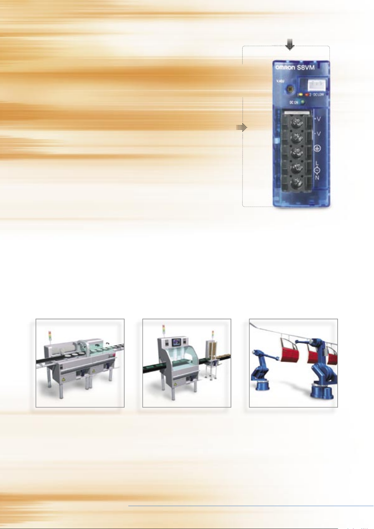
Just a single click onto a DIN-rail.
Moulded plastic front cover
eliminating any possibility of electric shock due
to fingers touching high-voltage parts.
Screw-terminal block
providing additional
finger protection.
Undervoltage alarm/LED indication.
New ultra-compact housing.
Connector for signal output
of undervoltage alarm.
For fast and accurate action
to minimise machine downtime

Advanced Industrial Automation
Momentary drop
in output voltage
DC LOW1 (Yellow LED) lit
Due most likely to a fault on the
input of the power supply or a
transient abnormality in the load.
Gradual drop in output voltage
to below 20 V; remaining low
DC LOW2 (Red LED) lit
Due most likely to degradation
in power supply components due
to age.
Output voltage remains low
following sudden voltage drop
DC LOW1 & 2 (red and
yellow LEDs) lit
Due most likely to a fault such
as a short circuit in the load.
Early warning
are due to deterioration of the power supply, abnormal input
or an abnormality in the electrical circuit of the cabinet by
means of 2 LEDs (yellow and red) on the front of the housing.
Early-warning system
In addition to the LED indication, the 24 V models with output
powers of 50 W and higher also provide an undervoltage alarm
output. This can convey an on/off signal through a wire to, for
example, a PLC or HMI to help provide a visible fault warning
at a remote location. The signal can also be used to switch
on a lamp or cause it to flash continuously.
Timely, efficient on-site troubleshooting for optimum
quality management
The S8VM series is unique in offering an undervoltage alarm
with a diagnostic function to aid on-site troubleshooting.
This enables you to go straight to the heart of a problem,
whether in the mains supply, the electrical circuit of the cabinet
or the power supply itself. The result – fast, effective remedial
action with no costly delays!
Featured on all 24 V output power supplies, the S8VM’s
troubleshooting function lets you determine whether faults
Output voltage
Time
ON ON
ON OFF
1
2
Output voltage
Time
ON
1
2
Output voltage
Time
ON
ON
1
2
Advanced Industrial Automation
New ultra-compact housing supports cabinet downsizing
Supporting the trend for ever-greater downsizing in industrial
equipment, Omron placed top priority on internal circuit layout
to minimise size without compromising thermal performance.
The result – a new ultra-slim housing that can be
accommodated in virtually any cabinet and in any position
within a cabinet. What’s more, a standard housing height of
84.5 mm for all power ratings further simplifies cabinet design.
Broad product range meeting your diverse needs
Meeting the diverse demands of industrial users, the single-
phase S8VM series is available in a broad range of DC output
voltages from 5 V up to 24 V and in powers from 15 W to 150 W.
Moreover, the range will be extended to cover even higher
powers from 300 W right up to 1500 W in early 2006.
And that’s not all. To support industrial manufacturers serving
international markets, the series complies with all relevant
international safety standards. And reflecting Omron’s ongoing
commitment to environmental protection, the series already
meets RoHS requirements, which set limits on the presence
of hazardous substances, such as lead.
Semiconductor manufacture demands
sophisticated and highly-reliable
production machinery to process
sensitive wafers and other
semiconductor components.
To maintain continuous production
processes, any faults in the
production equipment must be
quickly traced and corrected.
The fiercely-competitive automotive
industry relies on robust and highly-
reliable robotic production equipment
to guarantee minimum downtime.
Semiconductor wafer production Continuous production processes Robotics in the automotive industry
New
ultra-compact
housing

Switch Mode Power Supply S8VM 1
Switch Mode Power Supply
S8VM (15/30/50/100/150-W Models)
Power Supply Featuring OMRON’s Unique,
New Undervoltage Alarm Function with
Compact Body Contributing to Machine
Downsizing
• New undervoltage alarm function assists in determining causes
of errors (S8VM-@@@24A
@/P@ only).
• Broad range of possibilities with 5 capacities and 20 models to
choose from.
• RoHS compliant, including lead-free construction.
• Safety standards:
UL508/60950-1/1604, CSA C22.2 No. 14/No. 60950-1/No. 213,
EN50178, EN60950-1
• Harmonic current emissions: Conforms to EN61000-3-2.
• New, attentive design prevents screws from falling out of
terminal block.
• Finger protection prevents electric shock.
• DIN Rail mounting.
Note: Refer to Precautions for Safe Use on page 19.
Note: 300- to 1,500-W models will be released in 2006.
Model Number Structure
� Model Number Legend
Note: Not all combinations are possible. Please refer to the list of models in Ordering Information on page 2.
Note: 1. The front-mounting type cannot be used as a back-mounting type. For a back-mounting configuration, use a DIN Rail mounting bracket
type.
2. The housing and terminal of the connector for the undervoltage alarm output are provided with the S8VM-05024A
@/P@, S8VM-
10024A
@/P@ and S8VM-15024A@/P@.
1 2
3
4
S8VM- @@@@@@@
1. Power Ratings
015: 15 W
030: 30 W
050: 50 W
100: 100 W
150: 150 W
2. Output voltage
05: 5 V
12: 12 V
15: 15 V
24: 24 V
3. Configuration/function
None: Open-frame type Standard type
C: Covered type Standard type
A: Covered type Undervoltage alarm type (Sinking)
(See note.)
P: Covered type Undervoltage alarm type (Sourcing)
(See note.)
4. Configuration
None Front-mounting type
D DIN Rail mounting bracket type
Switch Mode Power Supply S8VM 5
2 Switch Mode Power Supply S8VM
Ordering Information
Note: S8VM-@@@@@CD and S8VM-@@@@@PD models are standard inventory items, for other items please contact your OMRON
representative or distributor.
Note: 1. No outputs are built into these models.
2. The output capacity of the S8VM-15005@@ is 135 W.
Configura-
tion
Power
ratings
Input voltage Output voltage Output current Front-mounting DIN Rail mounting bracket
Standard type Undervoltage alarm type Standard type Undervoltage alarm type
Sinking Sourcing Sinking Sourcing
Open-frame
type
15 W 100 to 240 VAC 5 V 3 A S8VM-01505 --- --- S8VM-01505D --- ---
12 V 1.3 A S8VM-01512 --- --- S8VM-01512D --- ---
15 V 1 A S8VM-01515 --- --- S8VM-01515D --- ---
24 V 0.65 A S8VM-01524 --- --- S8VM-01524D --- ---
30 W 5 V 6 A S8VM-03005 --- --- S8VM-03005D --- ---
12 V 2.5 A S8VM-03012 --- --- S8VM-03012D --- ---
15 V 2 A S8VM-03015 --- --- S8VM-03015D --- ---
24 V 1.3 A S8VM-03024 --- --- S8VM-03024D --- ---
50 W 5 V 10 A S8VM-05005 --- --- S8VM-05005D --- ---
12 V 4.3 A S8VM-05012 --- --- S8VM-05012D --- ---
15 V 3.5 A S8VM-05015 --- --- S8VM-05015D --- ---
24 V 2.2 A S8VM-05024 --- --- S8VM-05024D --- ---
100 W 5 V 20 A S8VM-10005 --- --- S8VM-10005D --- ---
12 V 8.5 A S8VM-10012 --- --- S8VM-10012D --- ---
15 V 7 A S8VM-10015 --- --- S8VM-10015D --- ---
24 V 4.5 A S8VM-10024 --- --- S8VM-10024D --- ---
150 W 5 V 27 A S8VM-15005
(See note 2.)
--- --- S8VM-15005D
(See note 2.)
--- ---
12 V 12.5 A S8VM-15012 --- --- S8VM-15012D --- ---
15 V 10 A S8VM-15015 --- --- S8VM-15015D --- ---
24 V 6.5 A S8VM-15024 --- --- S8VM-15024D --- ---
Covered
type
15 W 100 to 240 VAC 5 V 3 A S8VM-01505C --- --- S8VM-01505CD --- ---
12 V 1.3 A S8VM-01512C --- --- S8VM-01512CD --- ---
15 V 1 A S8VM-01515C --- --- S8VM-01515CD --- ---
24 V 0.65 A S8VM-01524C S8VM-01524A (See note 1.) S8VM-01524CD S8VM-01524AD (See note 1.)
30 W 5 V 6 A S8VM-03005C --- --- S8VM-03005CD --- ---
12 V 2.5 A S8VM-03012C --- --- S8VM-03012CD --- ---
15 V 2 A S8VM-03015C --- --- S8VM-03015CD --- ---
24 V 1.3 A S8VM-03024C S8VM-03024A (See note 1.) S8VM-03024CD S8VM-03024AD (See note 1.)
50 W 5 V 10 A S8VM-05005C --- --- S8VM-05005CD --- ---
12 V 4.3 A S8VM-05012C --- --- S8VM-05012CD --- ---
15 V 3.5 A S8VM-05015C --- --- S8VM-05015CD --- ---
24 V 2.2 A S8VM-05024C S8VM-05024A S8VM-05024P S8VM-05024CD S8VM-05024AD S8VM-05024PD
100 W 5 V 20 A S8VM-10005C --- --- S8VM-10005CD --- ---
12 V 8.5 A S8VM-10012C --- --- S8VM-10012CD --- ---
15 V 7 A S8VM-10015C --- --- S8VM-10015CD --- ---
24 V 4.5 A S8VM-10024C S8VM-10024A S8VM-10024P S8VM-10024CD S8VM-10024AD S8VM-10024PD
150 W 5 V 27 A S8VM-15005C
(See note 2.)
--- --- S8VM-15005CD
(See note 2.)
--- ---
12 V 12.5 A S8VM-15012C --- --- S8VM-15012CD --- ---
15 V 10 A S8VM-15015C --- --- S8VM-15015CD --- ---
24 V 6.5 A S8VM-15024C S8VM-15024A S8VM-15024P S8VM-15024CD S8VM-15024AD S8VM-15024PD
Switch Mode Power Supply S8VM6

Switch Mode Power Supply S8VM 3
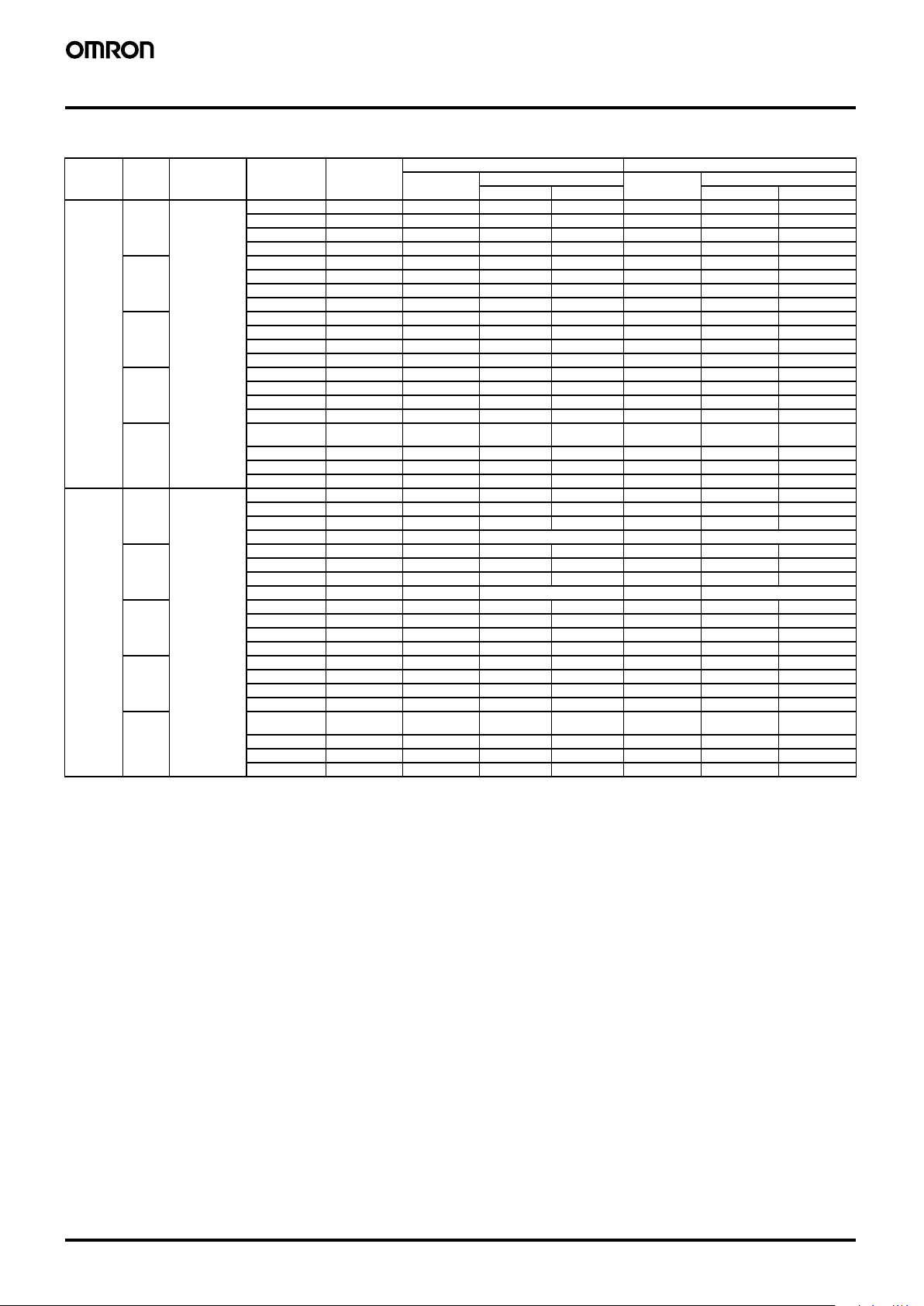
Specifications
� Ratings/Characteristics
Note: 1. Do not use the Inverter output for the Power Supply. Inverters with an output frequency of 50/60 Hz are available, but the rise in the internal temperature of the Power
Supply may result in ignition or burning.
2. Refer to the Engineering Data section on page 7 to 8 for details.
3. If the V. ADJ adjuster is turned, the voltage will increase by more than +20% of the voltage adjustment range.
When adjusting the output voltage, confirm the actual output voltage from the Power Supply and be sure that the load is not damaged.
4. To reset the protection, turn OFF the input power for three minutes or longer and then turn it back ON.
5. Conducted emissions: The noise value is affected by factors such as the wiring method. The product conforms to Class B when the aluminum plate is laid under the
product. For 15-W models, insert a clamp filter (ZCAT2436-1330 by TDK: 50
Ω min. [50 to 500 MHz], or the equivalent) in the output wire to reduce noise.
6. Radiated emissions: The noise value is affected by factors such as the wiring method. The product conforms to Class B when the aluminum plate is laid under the product.
For 150-W models, insert a clamp filter (ZCAT2017-0930 by TDK: 35
Ω min. [50 to 500 MHz], or the equivalent) in the input wire to reduce noise.
7. UL1604 (Class I/Division 2) and CSA C22.2 No. 213 (Class I/Division 2) approval pending for 150-W models. However, S8VM-15024@@ models are designed for com-
pliance with an output rated current of 6.3 A max.
8. The weight indicated is for front-mounting, open-frame models.
9.
A@: Sinking type (NPN)
P@: Sourcing type (PNP)
Item Power ratings 15 W 30 W 50 W 100 W 150 W
Efficiency 5-V models 75% min. 75% min. 80% min. 81% min. 81% min.
12-V models 78% min. 79% min. 79% min. 81% min. 81% min.
15-V models 78% min. 79% min. 79% min. 81% min. 81% min.
24-V models 80% min. 81% min. 80% min. 82% min. 83% min.
Input Voltage (See note 1.) 100 to 240 VAC (85 to 264 VAC)
Frequency (See note 1.) 50/60 Hz (47 to 63Hz)
Current 100-V input 0.5 A max. 0.9 A max. 0.8 A max. 1.4 A max. 2.0 A max.
200-V input 0.25 A max. 0.45 A max. 0.4 A max. 0.7 A max. 1.0 A max.
Power factor 100-V input --- 0.98 min.
200-V input --- 0.94 min.
Harmonic current emissions --- Conforms to EN 61000-3-2
Leakage current 100-V input 0.4 mA max. (at rated output)
200-V input 0.75 mA max. (at rated output)
Inrush current
(See note 2.)
100-V input 17.5 A max. (for cold start at 25
° C)
200-V input 35 A max. (for cold start at 25
° C)
Output Voltage adjustment range (See note 3.)
−20% to 20% (with V. ADJ) (S8VM-@@@24A@/P@: −10% to 20%)
Ripple 3.2% (p-p) max. (5 V),
1.5% (p-p) max. (12 V),
1.2% (p-p) max. (15 V),
1.0% (p-p) max. (24 V),
(at rated input/output voltage)
3.2% (p-p) max. (5 V),
1.5% (p-p) max. (12 V),
1.2% (p-p) max. (15 V),
0.75% (p-p) max. (24 V),
(at rated input/output voltage)
Input variation influence 0.4% max. (at 85 to 264 VAC input, 100%)
Load variation influence (rated input voltage) 0.8% max. (with rated input, 0 to 100% load)
Temperature variation influence 0.02%/
° C max.
Start up time (See note 2.) 1,100 ms max. (at rated input/output voltage) 800 ms max. (at rated input/output voltage)
Hold time (See note 2.) 20 ms typ. (15 ms min.) (at rated input/output voltage)
Additional
functions
Overload protection
(See note 2.)
105% to 160% of rated load current, voltage
drop, intermittent, automatic reset
105% to 160% of rated load current,
voltage drop (12 V, 15 V, and 24 V),
voltage drop, intermittent (5 V),
automatic reset
Overvoltage protection
(See note 2.)
Yes (See note 4.)
Undervoltage alarm indication Yes (color: yellow (DC LOW1), red (DC LOW2)) (S8VM-@@@24A
@/P@ only)
Undervoltage alarm output No Yes (S8VM-@@@24A
@/P@ only)
(Transistor output), 30 VDC max., 50 mA max.) (See note 9.)
Series operation Yes
Parallel operation No
Remote sensing function No Yes
Other Operating ambient temperature Refer to the derating curve in Engineering Data. (with no icing or condensation) (See note 2.)
Storage temperature
−25 to 65° C
Operating ambient humidity 30% to 85% (Storage humidity: 25% to 90%)
Dielectric strength 3.0 kVAC for 1 min. (between all inputs and outputs; detection current: 20 mA)
2.0 kVAC for 1 min. (between all inputs and PE/FG terminals; detection current: 20 mA)
500 VAC for 1 min. (between all outputs and PE/FG terminals; detection current: 100 mA)
500 VAC for 1 min. (between all outputs (except the detection output terminals) and detection output terminals; detection current: 20 mA) (S8VM-@@@24A@/P@ only)
Insulation resistance 100 M
Ω min. (between all outputs and all inputs, PE/FG terminals) at 500 VDC
Vibration resistance 10 to 55 Hz, 0.375-mm single amplitude for 2 hours each in X, Y, and Z directions
Shock resistance
150m/s
2
, 3 times each in ±X, ±Y, ±Z directions
Output indicator Yes (color: green)
EMI Conducted Emission Conforms to EN61204-3 EN55011 Class B and based on FCC Class B (See note 5.)
Radiated Emission Conforms to EN61204-3 EN55011 Class B (See note 6.)
EMS Conforms to EN61204-3 High severity levels
Approved standards
(See note 7.)
UL: UL508 (Listing), UL60950-1, UL1604 (Class
I/Division 2)
CSA: cUL: C22.2 No.14, cUR: No. 60950-1, No.213 (Class
I/Division 2)
EN: EN50178, EN60950-1
SELV (EN60950-1)
According to VDE0160/P100
Weight (See note 8.) 180 g max. 220 g max. 290 g max. 460 g max. 530 g max.
Switch Mode Power Supply S8VM 7

4 Switch Mode Power Supply S8VM
Connections
� Block Diagrams
Noise
filter
Overvoltage
detection circuit
Fuse
2 A
Rectifier/smoothing
circuit
Drive control
circuit
AC (L)
AC (N)
INPUT
/FG
Photocoupler
DC OUTPUT
−V
+V
Voltage
detection circuit
Rectification Smoothing
Overcurrent
detection circuit
Inrush
current
protection circuit
Undervoltage
detection
S8VM-01524A@
Undervoltage
alarm indication
DC LOW1
DC LOW2
S8VM-015@@@@ (15 W)
Noise
filter
Fuse
3.15 A
AC (L)
AC (N)
INPUT
DC OUTPUT
−V
+V
Undervoltage
detection
Undervoltage
alarm indication
DC LOW1
DC LOW2
S8VM-03024A@
/FG
Overvoltage
detection circuit
Rectifier/smoothing
circuit
Drive control
circuit
Photocoupler
Voltage
detection circuit
Rectification Smoothing
Inrush
current
protection circuit
Overcurrent
detection circuit
S8VM-030@@@@ (30 W)
Fuse
2 A
AC (L)
AC (N)
INPUT
DC OUTPUT
−V
+V
Alarm
DC LOW1
Common
Inrush
current
protection
circuit
Undervoltage
detection
Alarm
DC LOW2
S8VM-05024A@ (Sinking)
DC LOW1
DC LOW2
Undervoltage
alarm indication
/FG
Noise
filter
Overvoltage
detection circuit
Rectifier/smoothing
circuit
Drive control
circuit
Photocoupler
Voltage
detection circuit
Rectification
Smooth-
ing
Harmonic
current
suppression
Photocoupler
Overcurrent
detection circuit
Alarm
DC LOW1
Common
Undervoltage
detection
Alarm
DC LOW2
S8VM-05024P@ (Sourcing)
DC LOW1
DC LOW2
Undervoltage
alarm indication
Photocoupler
S8VM-050@@@@ (50 W)
Switch Mode Power Supply S8VM8

Switch Mode Power Supply S8VM 5
DC OUTPUT
−V
+V
Alarm
DC LOW1
Common
Undervoltage
detection
Alarm
DC LOW2
INPUT
AC (N)
AC (L)
Fuse
3.15 A
Drive
S8VM-10024A@ (Sinking)
Remote sensing
+S
−S
DC LOW1
DC LOW2
Undervoltage
alarm indication
/FG
Inrush
current
protection
circuit
Noise
filter
Overvoltage
detection circuit
Rectifier/smoothing
circuit
Drive control
circuit
Photocoupler
Voltage
detection circuit
Rectification
Smooth-
ing
Overcurrent
detection circuit
Harmonic
current
suppression
Photocoupler
Alarm
DC LOW1
Common
Undervoltage
detection
Alarm
DC LOW2
S8VM-10024P@ (Sourcing)
DC LOW1
DC LOW2
Undervoltage
alarm indication
Photocoupler
S8VM-100@@@@ (100 W)
DC OUTPUT
−V
+V
Alarm
DC LOW1
Common
Undervoltage
detection
Alarm
DC LOW2
INPUT
AC (N)
AC (L)
Fuse
5 A
Drive
Remote sensing
+S
−S
DC LOW1
DC LOW2
Undervoltage
alarm indication
S8VM-15024A@ (Sinking)
/FG
Inrush
current
protection
circuit
Noise
filter
Overvoltage
detection circuit
Rectifier/smoothing
circuit
Drive control
circuit
Photocoupler
Voltage
detection circuit
Rectification
Smooth-
ing
Harmonic
current
suppression
Photocoupler
Overcurrent
detection circuit
Alarm
DC LOW1
Common
Undervoltage
detection
Alarm
DC LOW2
S8VM-15024P@ (Sourcing)
DC LOW1
DC LOW2
Undervoltage
alarm indication
Photocoupler
S8VM-150@@@@ (150 W)
Switch Mode Power Supply S8VM 9
 Loading...