

Omron S8VK-R, S8VK-R10, S8VK-R20 Safety
New Product
! Refer to Safety Precautions on page 8.
1
Series name
S8VK-R @@
Redundancy Unit
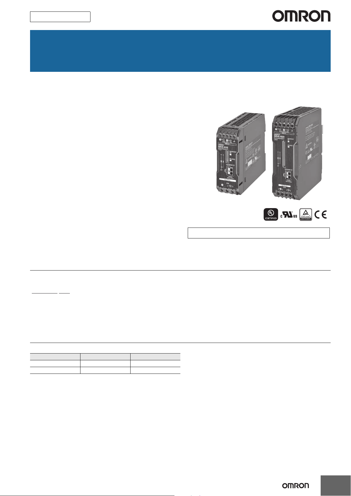
S8VK-R
Contribute to build high reliable systems
Compact and Cost-effective solution
for Back-up applications
Easy setup for system reliability
requirement
• Redundancy operating LED for the status confirmation
• A signal output for failure detection of power supplies
• Wide range input
DC5-30V (S8VK-R10), DC10-60V (S8VK-R20)
• Wide operation temperature range: -40 to 70 °C
• Safety standards:
UL508/60950-1, CSA C22.2 No. 107.1/60950-1
EN50178, EN60950-1
• EMS: EN61000-6-2
EMI: EN61000-6-3
Lloyd's standards
• Three years warranty *
* Refer to Period and Terms of Warranty on page 10.
Model Number Structure
Model Number Legend
1. Output current
10: 10 A
20: 20 A
Ordering Information
Note: For details on normal stock models, contact your nearest OMRON representative.
Input voltage Output current Model number
5 to 30 VDC 10 A S8VK-R10
10 to 60 VDC 20 A S8VK-R20
1
S8VK-R
Specifications
Ratings, Characteristics, and Functions
I te m Model number S8VK-R10 S8VK-R20
Rated input voltage 5 to 30 VDC 10 to 60 VDC
Input/
output
Voltage
drop
Power
losses
Additional
functions
Others
Note: Ask your OMRON representative for information on the power losses and voltage drop resulting from application conditions.
* Refer to Power Boost Function in Engineering Data on page 4.
Allowable input current 0 to 10 A 0 to 20 A
Rated output current 10 A 20 A
Boost current 12 A * 24 A *
Input to Output
Indicator Yes (LED: Green)
REDUNDANCY OK
BALANCE Indicator Yes (LED: Green), Signal output: None
Ambient operating temperature -40 to 70°C (Refer to Engineering Data)
Storage temperature -40 to 85°C
Ambient operating humidity 0% to 95% (Storage humidity: 0% to 95%)
Dielectric strength
Vibration resistance 10 to 55 Hz, 0.375-mm half amplitude for 2 h each in X, Y, and Z directions
Shock resistance 150 m/s2, 3 times each in ±X, ±Y, and ±Z directions
EMI
EMS Conforms to EN 61000-6-2
Approved Standards
Marine standards LR standards
Degree of protection IP20 by EN/IEC60529
Weight 195 g max. 495 g max.
Contact
Conducted
Emission
Radiated
Emission
0.56 V typ. 2x5 A
0.63 V typ. 1x10 A
6.5 W 2x5 A
7.1 W 1x10 A
0.8 W 0 A
Yes, photo switch contact
30 VDC max., 50 mA max., residual voltage when ON: 2 V max., leakage current when OFF:
0.1 mA max.
1.0 kVAC for 1 min (between all input/output terminals and terminal)
0.5 kVAC for 1 min (between all input/output terminals and signal output terminals)
1.0 kVAC for 1 min (between signal output terminals and terminal)
Conforms to EN 61000-6-3 EN 55011 Class B
Conforms to EN 61000-6-3 EN 55011 Class B
UL Listed: UL 508 (Listing)
UL UR: UL 60950-1 (Recognition)
cUL: CSA C 22.2 No.107.1
cUR: CSA C 22.2 No.60950-1
EN: EN 50178, EN 60950-1
0.67 V typ. 2x10 A
0.78 V typ. 1x20 A
15.8 W 2x10 A
18.0 W 1x20 A
0.8 W 0 A
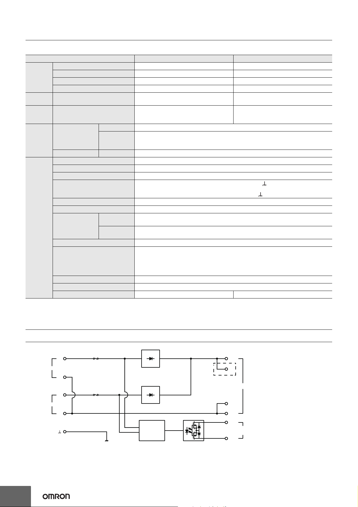
Connections
Block Diagrams
IN 1
IN 2
2
+V
+V
Fuse
S8VK-R10: 20 A
-V
-V
S8VK-R20: 40 A
Fuse
S8VK-R10: 20 A
S8VK-R20: 40 A
S8VK-R20 only
Detection
circuit
+V
+V
OUTPUT
-V
-V
REDUNDANCY
OK
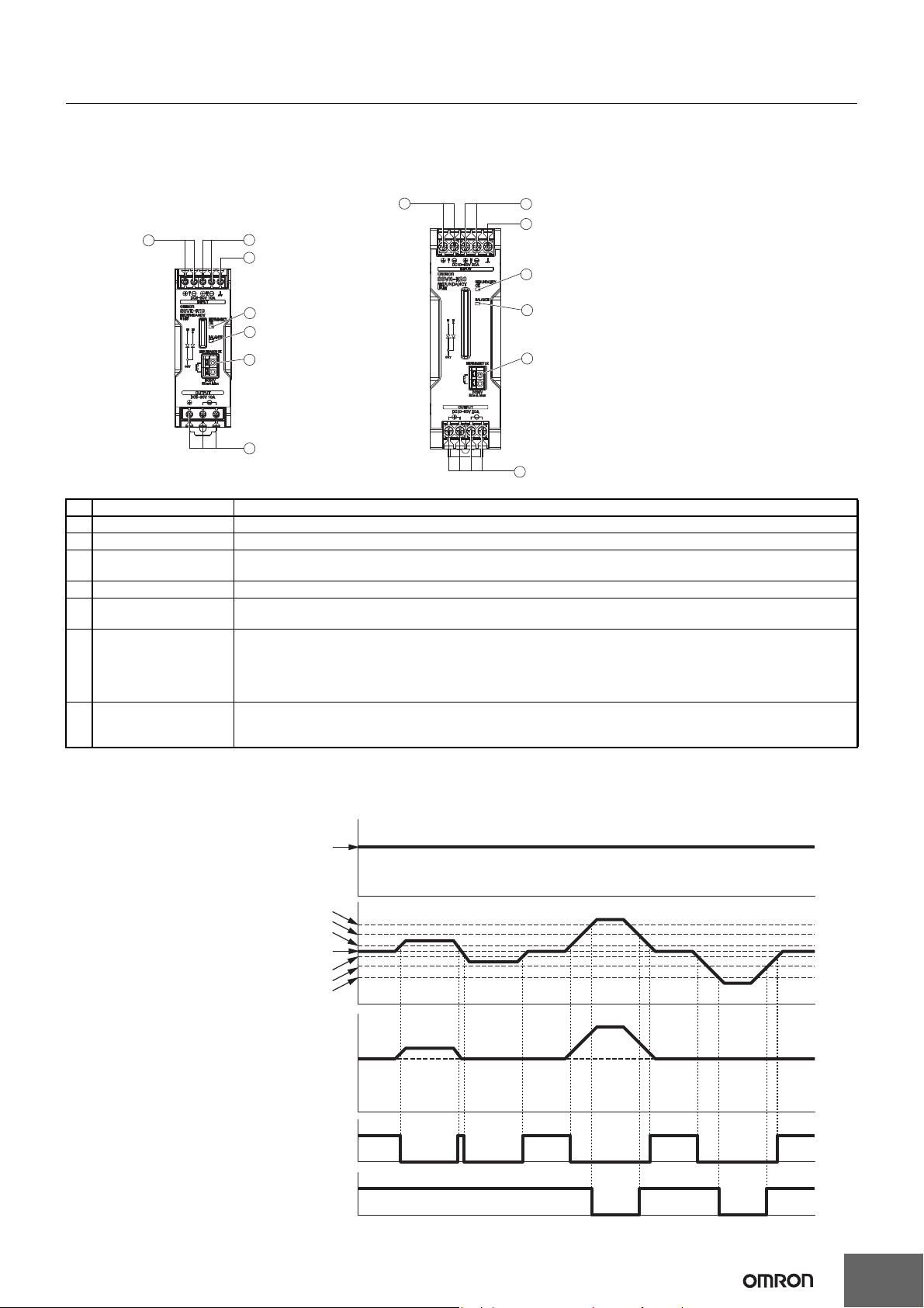
Construction and Nomenclature
3
2
6
5
4
7
1
3
2
6
5
4
7
1
Vin
+50 mV
−50 mV
+2.4 V
−2.4 V
Vin
+1.2 V
Vout
−1.2 V
LED not lit and photo switch
contact OFF.
LED lit and photo switch
contact ON.
LED not lit.
LED lit.
Input voltage 1
Input voltage 2
Output voltage
Voltage balance indicator
Redundancy OK
(indicator and signal output)
Nomenclature
10 A Model 20 A Model
S8VK-R10 S8VK-R20
S8VK-R
No. Name Function
1 Input terminal 1 Connect the input 1 lines to these terminals.
2 Input terminal 2 Connect the input 2 lines to these terminals.
3 Ground terminal This is not an earth terminal. Functionality and safety will not be affected even when this terminal is not connected
to the ground.
4 Output terminal Connect the load lines to these terminals.
5 Status indicator:
(redundancy OK: Green)
6 Status indicator:
(voltage balance: Green)
The LED lights when the voltage difference between the two power supplies is 1.2 V or less.
If the voltage difference exceeds 2.4 V, the LED will turn OFF. *1
The LED lights when the voltage difference between the two power supplies is 50 mV or less. *1
If you use the S8VK-G 120 W to 480 W(*2), you can assume that the output current from the two power supplies
is balanced when this LED is lit.
With application when the output current is balanced , you can assume that the life expectancy of the two power
supplies will be longer in comparison with application when the output current is not balanced.
7 Signal output terminal:
redundancy OK
The photo switch contact turns ON when the voltage difference between the two power supplies is 1.2 V or less.
The photo switch contact turns OFF when the voltage difference between the two power supplies exceeds 2.4 V. *1
(photo switch)
*1. Refer to Operation Timing for an illustration of operation.
*2. Contact your OMRON representative before you use this function for any model other than the S8VK-G.
Operation Timing
3
S8VK-R
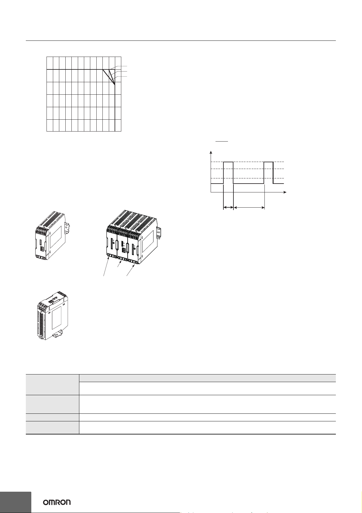
A: Standard mounting
B: Standard mounting (contact mounting), 60°C and over: the derating
is 2.5%/°C (Contact mounting is possible only with the S8VK-G;
safety standards will not apply.)
C: Face-up mounting
50°C and over: the derating is 1.25%/°C
(B) Standard Mounting
(Contact mounting)
(C) Face-up mounting
(A) Standard (Vertical) mounting
S8VK-R
Switch Mode Power Supplies
(Must be S8VK-G.)
Engineering Data
Derating Curve
120
100
80
Load ratio (%)
60
40
20
0
−40 −25 −10 0 10 20 30 40 50 60 70 80
Ambient temperature (°C)
Mounting
Power Boost Function
This function is possible when used in combination with S8VK-G (All
A
B
C
Models).
Power Boost is a function that can output the temporary repeated
boost current larger than the rated current.
However, it should meet the following four Boost current conditions.
1. Time that the boost current flows: t1
2. The maximum value of the boost current: lp
3. The average output current: lave
4. The time ratio of the boost current flow: Duty
Note: Boost Current Conditions
• t1
≤ 10 s
• Ip
≤ Boost current (S8VK-R10: 12 A, S8VK-R20: 24 A)
• lave
≤ Rated output current
t1
t1 + t2
t1
× 100 [%] ≤ 30%
Ip: Boost current
Rated current
lave: Average current
t2
Duty=
[A]
output current
• Do not allow the boost current to continue for more than 10
seconds.
Also, do not let the duty cycle exceed the boost current conditions.
These conditions may damage the Power supply.
• Ensure that the average current of one cycle of the boost current
does not exceed the rated output current.
This may damage the Power Supply.
• Lessen the load of the boost load current by adjusting the ambient
temperature and the mounting direction.
* Refer to Mounting on page 9.
Reference Value
Reliability (MTBF)
Definition
Life expectancy 10 yrs. Min.
Definition
4
Value
S8VK-R10: 720,000 hrs.
S8VK-R20: 680,000 hrs.
MTBF stands for Mean Time Between Failures, which is calculated according to the probability of accidental device
failures, and indicates reliability of devices.
Therefore, it does not necessarily represent a life of the product.
The life expectancy indicates average operating hours under the ambient temperature of 40°C and a load rate of 50%.
Normally this is determined by the life expectancy of the built-in aluminum electrolytic capacitor.
 Loading...