

Page 1
New Product
! Refer to Safety Precautions on page 8.
1
Series name
S8VK-R @@
Redundancy Unit
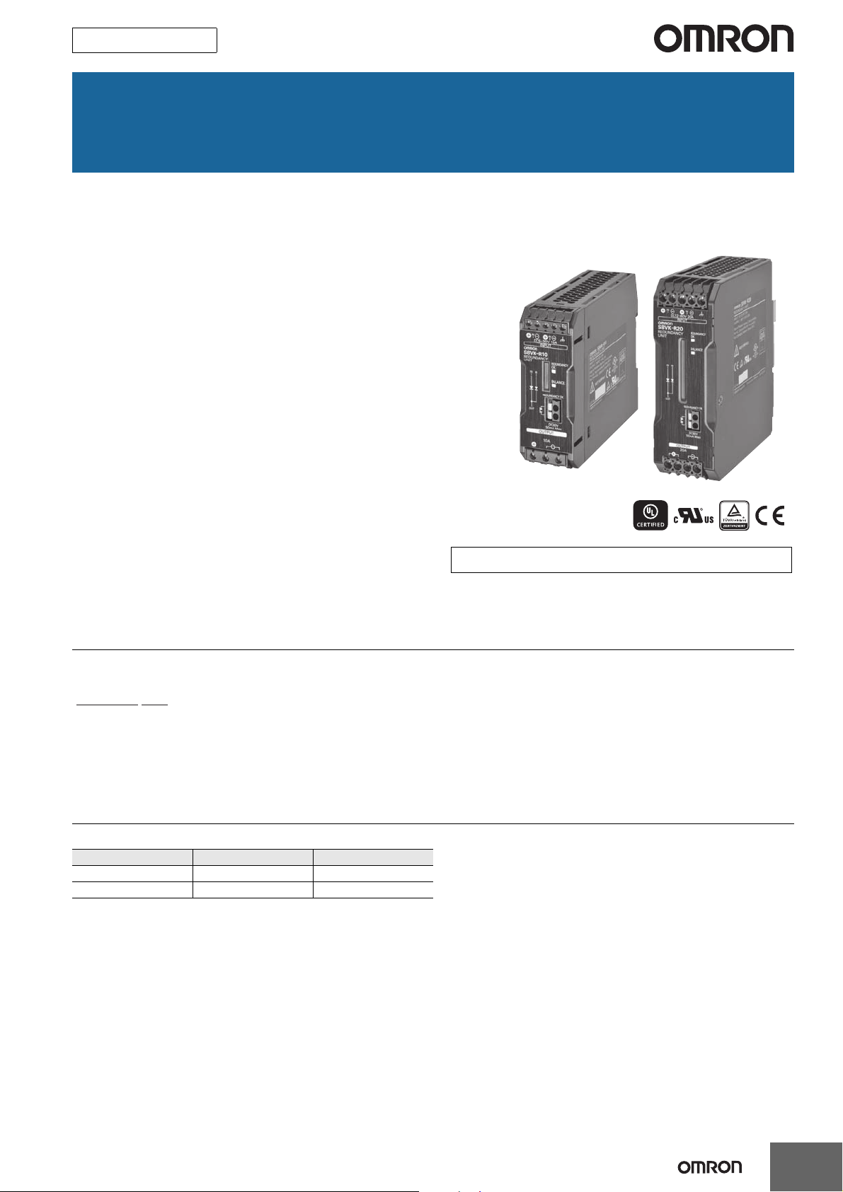
S8VK-R
Contribute to build high reliable systems
Compact and Cost-effective solution
for Back-up applications
Easy setup for system reliability
requirement
• Redundancy operating LED for the status confirmation
• A signal output for failure detection of power supplies
• Wide range input
DC5-30V (S8VK-R10), DC10-60V (S8VK-R20)
• Wide operation temperature range: -40 to 70 °C
• Safety standards:
UL508/60950-1, CSA C22.2 No. 107.1/60950-1
EN50178, EN60950-1
• EMS: EN61000-6-2
EMI: EN61000-6-3
Lloyd's standards
• Three years warranty *
* Refer to Period and Terms of Warranty on page 10.
Model Number Structure
Model Number Legend
1. Output current
10: 10 A
20: 20 A
Ordering Information
Note: For details on normal stock models, contact your nearest OMRON representative.
Input voltage Output current Model number
5 to 30 VDC 10 A S8VK-R10
10 to 60 VDC 20 A S8VK-R20
1
Page 2
S8VK-R
Specifications
Ratings, Characteristics, and Functions
I te m Model number S8VK-R10 S8VK-R20
Rated input voltage 5 to 30 VDC 10 to 60 VDC
Input/
output
Voltage
drop
Power
losses
Additional
functions
Others
Note: Ask your OMRON representative for information on the power losses and voltage drop resulting from application conditions.
* Refer to Power Boost Function in Engineering Data on page 4.
Allowable input current 0 to 10 A 0 to 20 A
Rated output current 10 A 20 A
Boost current 12 A * 24 A *
Input to Output
Indicator Yes (LED: Green)
REDUNDANCY OK
BALANCE Indicator Yes (LED: Green), Signal output: None
Ambient operating temperature -40 to 70°C (Refer to Engineering Data)
Storage temperature -40 to 85°C
Ambient operating humidity 0% to 95% (Storage humidity: 0% to 95%)
Dielectric strength
Vibration resistance 10 to 55 Hz, 0.375-mm half amplitude for 2 h each in X, Y, and Z directions
Shock resistance 150 m/s2, 3 times each in ±X, ±Y, and ±Z directions
EMI
EMS Conforms to EN 61000-6-2
Approved Standards
Marine standards LR standards
Degree of protection IP20 by EN/IEC60529
Weight 195 g max. 495 g max.
Contact
Conducted
Emission
Radiated
Emission
0.56 V typ. 2x5 A
0.63 V typ. 1x10 A
6.5 W 2x5 A
7.1 W 1x10 A
0.8 W 0 A
Yes, photo switch contact
30 VDC max., 50 mA max., residual voltage when ON: 2 V max., leakage current when OFF:
0.1 mA max.
1.0 kVAC for 1 min (between all input/output terminals and terminal)
0.5 kVAC for 1 min (between all input/output terminals and signal output terminals)
1.0 kVAC for 1 min (between signal output terminals and terminal)
Conforms to EN 61000-6-3 EN 55011 Class B
Conforms to EN 61000-6-3 EN 55011 Class B
UL Listed: UL 508 (Listing)
UL UR: UL 60950-1 (Recognition)
cUL: CSA C 22.2 No.107.1
cUR: CSA C 22.2 No.60950-1
EN: EN 50178, EN 60950-1
0.67 V typ. 2x10 A
0.78 V typ. 1x20 A
15.8 W 2x10 A
18.0 W 1x20 A
0.8 W 0 A
Connections
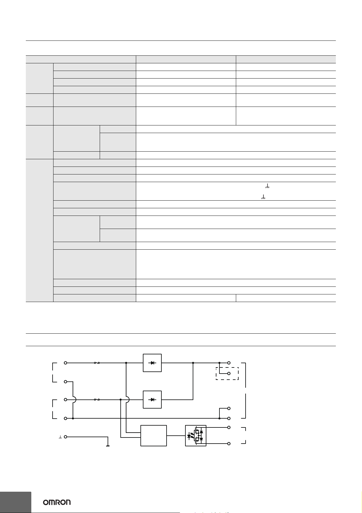
Block Diagrams
IN 1
IN 2
2
+V
+V
Fuse
S8VK-R10: 20 A
-V
-V
S8VK-R20: 40 A
Fuse
S8VK-R10: 20 A
S8VK-R20: 40 A
S8VK-R20 only
Detection
circuit
+V
+V
OUTPUT
-V
-V
REDUNDANCY
OK
Page 3
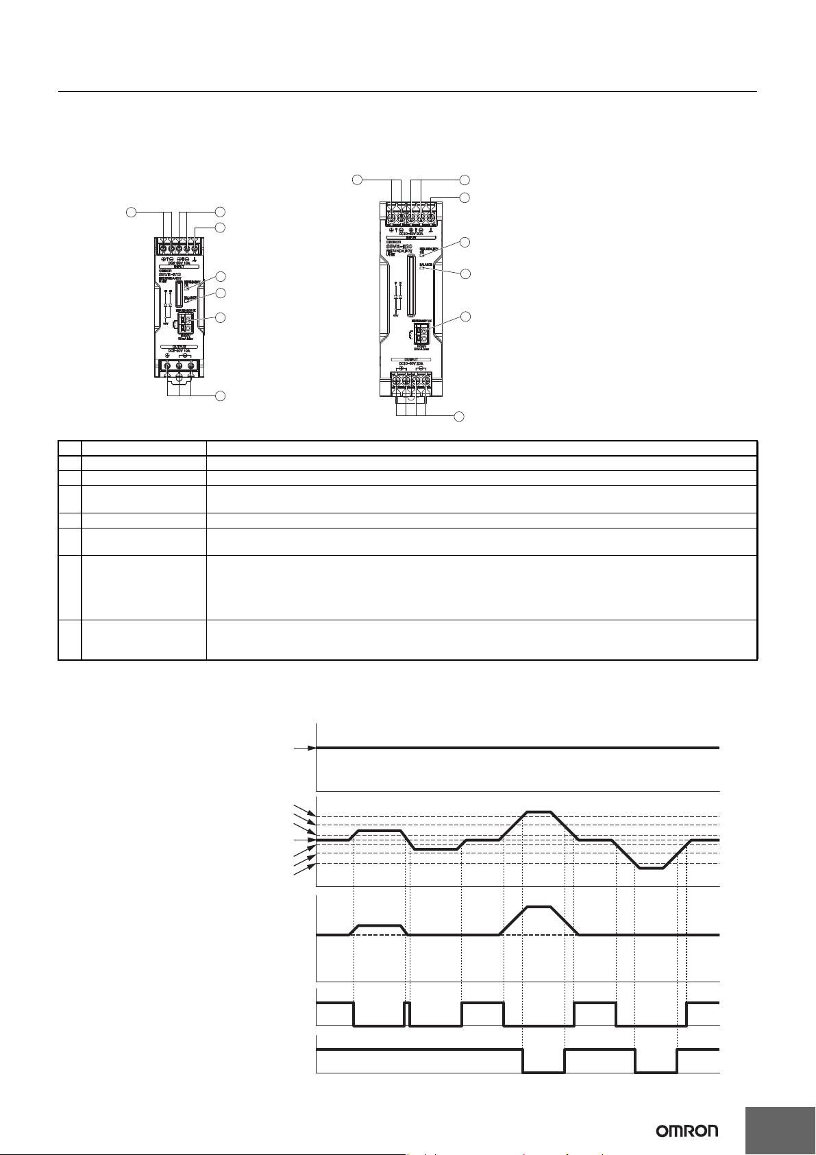
Construction and Nomenclature
3
2
6
5
4
7
1
3
2
6
5
4
7
1
Vin
+50 mV
−50 mV
+2.4 V
−2.4 V
Vin
+1.2 V
Vout
−1.2 V
LED not lit and photo switch
contact OFF.
LED lit and photo switch
contact ON.
LED not lit.
LED lit.
Input voltage 1
Input voltage 2
Output voltage
Voltage balance indicator
Redundancy OK
(indicator and signal output)
Nomenclature
10 A Model 20 A Model
S8VK-R10 S8VK-R20
S8VK-R
No. Name Function
1 Input terminal 1 Connect the input 1 lines to these terminals.
2 Input terminal 2 Connect the input 2 lines to these terminals.
3 Ground terminal This is not an earth terminal. Functionality and safety will not be affected even when this terminal is not connected
to the ground.
4 Output terminal Connect the load lines to these terminals.
5 Status indicator:
(redundancy OK: Green)
6 Status indicator:
(voltage balance: Green)
The LED lights when the voltage difference between the two power supplies is 1.2 V or less.
If the voltage difference exceeds 2.4 V, the LED will turn OFF. *1
The LED lights when the voltage difference between the two power supplies is 50 mV or less. *1
If you use the S8VK-G 120 W to 480 W(*2), you can assume that the output current from the two power supplies
is balanced when this LED is lit.
With application when the output current is balanced , you can assume that the life expectancy of the two power
supplies will be longer in comparison with application when the output current is not balanced.
7 Signal output terminal:
redundancy OK
The photo switch contact turns ON when the voltage difference between the two power supplies is 1.2 V or less.
The photo switch contact turns OFF when the voltage difference between the two power supplies exceeds 2.4 V. *1
(photo switch)
*1. Refer to Operation Timing for an illustration of operation.
*2. Contact your OMRON representative before you use this function for any model other than the S8VK-G.
Operation Timing
3
Page 4
S8VK-R
A: Standard mounting
B: Standard mounting (contact mounting), 60°C and over: the derating
is 2.5%/°C (Contact mounting is possible only with the S8VK-G;
safety standards will not apply.)
C: Face-up mounting
50°C and over: the derating is 1.25%/°C
(B) Standard Mounting
(Contact mounting)
(C) Face-up mounting
(A) Standard (Vertical) mounting
S8VK-R
Switch Mode Power Supplies
(Must be S8VK-G.)
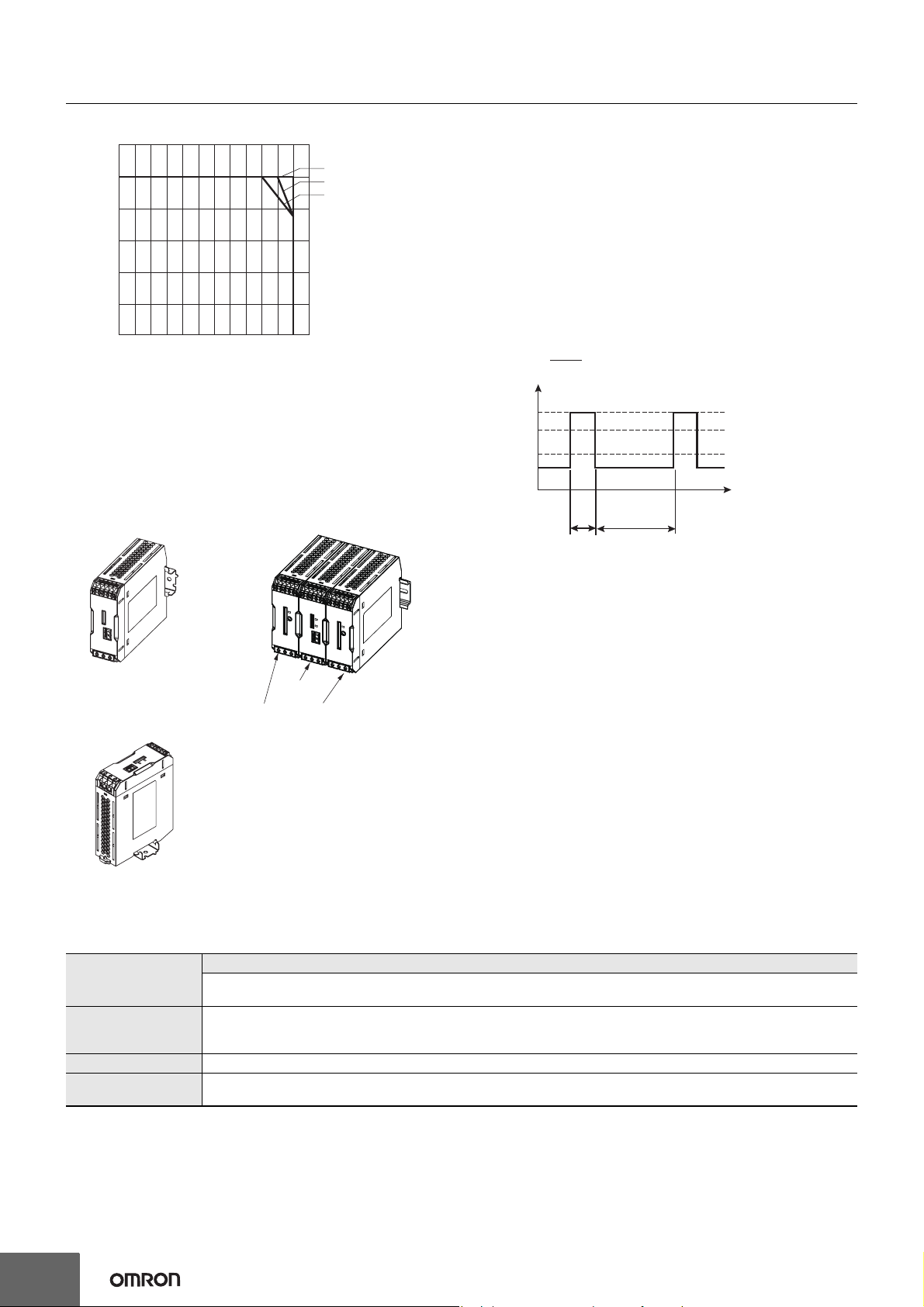
Engineering Data
Derating Curve
120
100
80
Load ratio (%)
60
40
20
0
−40 −25 −10 0 10 20 30 40 50 60 70 80
Ambient temperature (°C)
Mounting
Power Boost Function
This function is possible when used in combination with S8VK-G (All
A
B
C
Models).
Power Boost is a function that can output the temporary repeated
boost current larger than the rated current.
However, it should meet the following four Boost current conditions.
1. Time that the boost current flows: t1
2. The maximum value of the boost current: lp
3. The average output current: lave
4. The time ratio of the boost current flow: Duty
Note: Boost Current Conditions
• t1
≤ 10 s
• Ip
≤ Boost current (S8VK-R10: 12 A, S8VK-R20: 24 A)
• lave
≤ Rated output current
t1
t1 + t2
t1
× 100 [%] ≤ 30%
Ip: Boost current
Rated current
lave: Average current
t2
Duty=
[A]
output current
• Do not allow the boost current to continue for more than 10
seconds.
Also, do not let the duty cycle exceed the boost current conditions.
These conditions may damage the Power supply.
• Ensure that the average current of one cycle of the boost current
does not exceed the rated output current.
This may damage the Power Supply.
• Lessen the load of the boost load current by adjusting the ambient
temperature and the mounting direction.
* Refer to Mounting on page 9.
Reference Value
Reliability (MTBF)
Definition
Life expectancy 10 yrs. Min.
Definition
4
Value
S8VK-R10: 720,000 hrs.
S8VK-R20: 680,000 hrs.
MTBF stands for Mean Time Between Failures, which is calculated according to the probability of accidental device
failures, and indicates reliability of devices.
Therefore, it does not necessarily represent a life of the product.
The life expectancy indicates average operating hours under the ambient temperature of 40°C and a load rate of 50%.
Normally this is determined by the life expectancy of the built-in aluminum electrolytic capacitor.
Page 5

S8VK-R
S8VK-R10
117.8
112.2
(1)
(4)
(10)
19.8
6.35
6.35
8.2
Rail Stopper
40±1
104.6
20.5
5
4.7
(Sliding: 7.5 max.)
122.2
±1
125±1
Note: Be sure to use a #2 screwdriver
whose tip size is smaller than 4.9 mm
diameter and longer than 10 mm.
S8VK-R20
Dimensions (Unit: mm)
75.4
7.62
Rail Stopper
±1
32
5
8.5
5
5.7
16
4.7
(Sliding: 10 max.)
(1)
90±1
110
106
±1
3.5
Note: Be sure to use a #1 screwdriver
whose tip size is smaller than 3.5 mm
diameter and longer than 4.5 mm.
5
Page 6

S8VK-R
4.5
15 25 25
10 10
1,000 (500) *
25 25 15(5) *
35
±
0.3
7.3
±
0.15
27
±
0.15
1
* Values in parentheses are for the PFP-50N.
4.5
15 25 25
10 10
1,000
25 25 15
1 1.5
29.2242735
±
0.3
16
1.3
4.8
35.5
35.5
1.8
1.8
10
6.2
1
50
11.5
10
M4 spring washer
M4×8 pan-
head screw
DIN Rail (Order Separately)
Note: All units are in millimeters unless otherwise indicated.
Mounting Rail (Material: Aluminum)
PFP-100N
PFP-50N
Mounting Rail (Material: Aluminum)
PFP-100N2
End Plate
PFP-M
Note: If there is a possibility that the Unit will be subject to vibration or shock, use a steel DIN Rail. Otherwise, metallic filings may result from
aluminum abrasion.
6
Page 7

Mounting Brackets
Four, 4.5-dia. ±0.1
25±0.1
140±0.1
150
38
5.4
t = 2.0
Four,
4.5-dia.
±0.1
140
±0.1
50
±0.1
15.5
±0.1
150
73
4940
125
t = 2.0
Name Model
Front-mounting bracket (for S8VK-R10) S82Y-VS10F
Front-mounting bracket (for S8VK-R20) S82Y-VK10F
Side-mounting bracket (for S8VK-R10) S82Y-VS10S
Side-mounting bracket (for S8VK-R20) S82Y-VK10S
Note: Be sure to use the accessory screws.
Mounting screw tightening torque (recommended): 4.43 to 5.31 lb-in (0.5 to 0.6 N·m)
Type Model Dimensions Appearance
41
4.5 dia.±0.1
Front-mounting
bracket
(for S8VK-R10)
S82Y-VS10F
±0.1
35
40
50
t = 1.0
35
25
7.3
10
S8VK-R
Front-mounting
bracket
(for S8VK-R20)
Side-mounting
bracket
(for S8VK-R10)
Side-mounting
bracket
(for S8VK-R20)
S82Y-VK10F
S82Y-VS10S
S82Y-VK10S
±0.1
4.5 dia.
±0.1
80
35
64
55
60
±0.1
13
Left-side mounting Right-side mounting
t = 2.0
Left-side mounting * Right-side mounting *
* You can mount the side of the Power Supply to a DIN Rail by removing the DIN Rail Back-mounting Bracket and then attaching a Side-mounting
Bracket to the Power Supply.
7
Page 8

S8VK-R
W
L
Safety Precautions
Warning Indications
Indicates a potentially hazardous
CAUTION
situation which, if not avoided, may
result in minor or moderate injury or in
property damage.
Precautions for
Safe Use
Supplementary comments on what to
do or avoid doing, to use the product
safely.
Supplementary comments on what to
Precautions for
Correct Use
do or avoid doing, to prevent failure to
operate, malfunction or undesirable
effect on product performance.
Meaning of Product Safety Symbols
Used to warn of the risk of minor injury caused by
high temperatures.
Used for general mandatory action precautions
for which there is no specified symbol.
Use to indicate prohibition when there is a risk of
minor injury from electrical shock or other source
if the product is disassembled.
!CAUTION
Risk of a mild burn on rare occasions. Do not touch
the device unit while it is powered on or immediately
after the power is turned off.
Precautions for Safe Use
Wiring
1. Minor fire may possibly occur. Ensure that input and output
terminals are wired correctly.
2. Increases in the temperature of internal parts resulting from
heating of wiring materials may result in deterioration or damage
to parts. Use wiring materials suitable to the current being used.
The following wiring materials and strip length are recommended
to prevent heating and possible fires in wiring materials.
Input side: Use the following recommended wire type or the
Output side: Use the following recommended wire type or a wire
Terminal Model
Input
Output
Signal output S8VK-R@@ AWG16 1.5 mm
Refer to the following table for the wire diameters that are suitable
for the terminal blocks.
Applicable Wire Diameters and Cross-sectional Areas for Terminal Blocks
Model AWG Solid wire Twisted wire
S8VK-R10
S8VK-R20
recommended wire type of the connected power
supply.
type that has sufficient capacity for the current of the
two connected power supplies.
Recommended Wire Types and
Cross-sectional Areas
S8VK-R10
S8VK-R20
S8VK-R10
S8VK-R20
AWG24 to 12
AWG22 to 10
AWG Solid wire
AWG14 to 12 2.5 to 4 mm2
AWG12 to 10 4 to 6 mm24 mm
AWG14 to 12 2.5 to 4 mm22.5 mm
AWG12 to 10 4 to 6 mm24 mm
0.25 to 4 mm2
0.35 to 6 mm20.35 to 4 mm22.9 2.9
0.25 to 2.5 mm22.7 2.9
Twisted wire
2.5 mm
2
2
2
2
2
---
Terminal block
hole dimensions
W L
Wire
stripping
length
8 to 10
mm
Fire may occasionally occur. Tighten terminal screws
to the specified torque of 0.5 to 0.6 N·m.
Minor electric shock, fire, or Product failure may
occasionally occur. Do not allow any pieces of metal
or conductors or any clippings or cuttings resulting
from installation work to enter the Product.
Risk of product damage. Do not reverse the polarity
of the device input terminals when wiring.
Risk of internal component deterioration and
damage. Do not connect an AC power supply.
Minor electric shock, fire, or Product failure may
occasionally occur. Do not disassemble, modify, or
repair the Product or touch the interior of the
Product.
3. On rare occasions there is a risk of internal element deterioration
and damage if use is continued in a short-circuit or over-current
state.
4. Do not apply more than 75N force to the terminal block when
tightening it.
5. Use within a range that does not exceed the output current rating.
When a load short-circuit occurs, the short-circuit current of two
power supply units flows. Use output wiring that can handle the
short-circuit current of two units. If the wiring does not have
sufficient current capacity, connect a fuse on the output side.
Recommended fuse S8VK-R10: 15 A
If the current rating of the output terminal is exceeded on the
S8VK-R20, always use multiple terminals simultaneously.
6. Risk of damage to internal components. Do not use in a state that
S8VK-R20: 30 A
Fast-acting type
exceeds the rated current of the signal output.
Ambient Operating and Storage Environments
• Store the product with ambient temperature −40 to 85°C, and
relative humidity 0 to 95%.
• The internal parts may occasionally be deteriorated or broken. Do
not use at a temperature that exceed the operating temperature
range for the mounting type.
• Use the product where the relative humidity is 0 to 95%.
• Avoid places where the product is subjected to direct sunlight.
• Avoid places where the product is subjected to penetration of
liquid, foreign substance, or corrosive gas.
• Avoid places subject to shock or vibration. A device such as a
contact breaker may be a vibration source.
Set the Redundancy Unit as far as possible from possible sources
of shock or vibration.
• If the Redundancy Unit is used in an area with excessive electronic
noise or surge, be sure to separate the Redundancy Unit as far as
possible from the noise sources.
8
Page 9

Precautions for Correct Use
(A)
(B)
30 mm min.
Rail stopper
(C)
S8VK-R
Mounting
• The long-term reliability of the S8VK-R can be increased by
installing it properly and sufficiently considering heat dissipation.
• Install the S8VK-R so that the air flow circulates around it, because
the S8VK-R is designed to radiate heat by means of natural air
circulation.
• Can be used in a contact mounting with the S8VK-G (not covered
by safety certification). Two S8VK-G units cannot be mounted
together in a contact mounting.
*1
*2 *2
Powe r
supply
Powe r
supply
*1. Convention of air
*2. 20 mm min.
*1
DIN Rail Mounting
To mount the Redundancy Unit to a DIN Rail, pull down the rail
stopper until you hear it click, hook portion (A) of the Redundancy Unit
onto the DIN Rail, and press the Redundancy Unit in direction (B),
then, push up the rail stopper to lock the Redundancy Unit in place.
To remove the Redundancy Unit, pull down portion (C) with a flatblade screwdriver and pull off the Redundancy Unit.
Combinations
Combinations with the S8VK-S
Model number For parallel operation For backup operation
S8VK-S06024
S8VK-S12024
S8VK-S24024 - S8VK-R20
Combinations with the S8VK-G
Model number For parallel operation For backup operation
S8VK-G01505
S8VK-G01512
S8VK-G01524
S8VK-G03005
S8VK-G03012
S8VK-G03024
S8VK-G06012
S8VK-G06024
S8VK-G12024
S8VK-G24024
S8VK-G24048
S8VK-G48048 S8VK-R20
Combinations with the S8VK-C
Model number For parallel operation For backup operation
S8VK-C06024
S8VK-C12024
S8VK-C24024
S8VK-C48024
Combinations with the S8VK-T
Model number For parallel operation For backup operation
S8VK-T12024 S8VK-R10
S8VK-T24024 S8VK-R20
S8VK-T48024
S8VK-T96024 -
S8VK-R10 S8VK-R10
S8VK-R10
S8VK-R20
-
-
S8VK-R10
S8VK-R20S8VK-G48024 -
S8VK-R10
S8VK-R20
S8VK-R10
S8VK-R20
Dielectric Strength Test
• The S8VK-R is designed to withstand a voltage test of 1 kV AC for
one minute between all input/output terminals and the ground
terminal and between signal output terminals and the ground
terminal, and 0.5 kV AC for one minute between all input/output
Input Power Supply Selection
• This product contains an internal fuse. If a power supply other than
the recommended power supplies is used, the fuse may blow,
depending on the state of the load. Connect only the
recommended power supplies to the Redundancy Unit.
Recommended Power Supplies
• S8VK Series
• S8VS Series
• S8JX Series
• If you are building a redundant system, never use in a state that
exceeds the rated current of the power supply. If one of the power
supplies goes down, there is a risk that the voltage on the load side
cannot be attained.
• Use the same model for the power supplies that are connected.
• Do not use in applications where load rush current or overload may
frequently occur. Slight risk of deterioration and damage due to
internal loss.
terminals and the signal output terminal.
Note: 1.
The S8VK-R may possibly be damaged from the impulse
voltage if a testing device switch is used to abruptly apply or
shut off 1 kV AC, 0.5 kV AC. Increase the applied voltage
gradually using the voltage adjustment on the testing device.
2. When testing, always short-circuit all terminals to prevent
damage to the output terminal.
Signal output
• Photo switch output
30 VDC max. (LVLC), 50 mA max., residual voltage when ON: 2 V
max., leakage current when OFF: 0.1 mA max.
• Wire the signal output circuits correctly.
• The signal output circuits do not contain current-limiting circuits. Do
not allow the output current to exceed 50 mA.
• After you complete the wiring, confirm that operation is correct.
Status display LEDs
• The redundancy OK LED and signal output provide criteria for
checking the redundancy status from the electrical potential
difference between the two power supplies. It is not intended as a
conclusive means of determining the redundancy status. You must
periodically check the output voltage from the two power supplies.
9
Page 10

S8VK-R
(1) Failures that result from handling or operation of the product under conditions or in environments that are not given in this document and
not given in any other specifications exchanged between OMRON and the customer
(2) Failures that originate in causes other than the delivered product itself
(3) Failures caused by disassembly, modification, or repair of the product by anyone other than OMRON
(4) Failures caused by applications or uses for which the product was not originally intended
(5) Failures caused by factors that could not be anticipated with the scientific or technical knowledge available when the product was shipped
(6) Failures caused by other causes for which OMRON is not responsible, such as natural disasters and other acts of God
This warranty is limited to the individual product that was delivered and does not cover any secondary, subsequent, or related damages.
• The voltage balance display is not intended as a conclusive means
of determining the current balance. The degree of balance varies
by the model. If you require operation with balanced current, use
the same thickness and length of wiring from each power supply to
the S8VK-R and check the output current from each power supply.
• If you monitor the voltage balance display during voltage
adjustment, adjust the voltage of only one of the power supplies. If
you must adjust the voltages of both power supplies, be sure to
check the output voltage before use.
• Measure the voltage output from the S8VK-R with the primary side
voltage applied to only one of the connected power supplies and
adjust the voltage output from the power supply to the specified
output voltage.
• Then apply the primary side voltage to the other power supply and
adjust the voltage output from the power supply that was turned
ON last until the voltage balance indicator lights.
• This procedure will allow you to adjust the difference in the output
voltage from the two power supplies to within 50 mV of the
specified output voltage.
• The operation of the signal output and status indicator LEDs may
sometimes be unstable. When using in environments where the
temperature is less than −25°C, always adjust the 5-V power
supply to 5.3 V or higher.
Connections
It is possible to connect S8VK-R like below.
Power supply
L N
L
N
Period and Terms of Warranty
Warranty Period
The product warranty is valid for a period of three years from the date of shipment from the factory.
IN1
IN2
Redundancy
Unit
OUT
Power supply
L N
REDUNDANCY
MONITOR
Load
Terms of Warranty
The warranty is valid only for the following operating conditions.
1. Operation within the derating curve
2. Mounting method: Standard mounting
If the product fails for reasons attributable to OMRON within the above warranty period, OMRON will repair or replace the faulty part of the product
at the place of purchase or the place where the product delivered without charge.
This warranty does not cover the following types of failures.
Recommended Replacement Periods and Periodic Replacement for
Preventive Maintenance
The recommended replacement period for preventive maintenance is greatly influenced by the application environment of the product. As a
guideline, the recommended replacement period is 20 years.*
To prevent failures or accidents that can be caused by using a product beyond its service live, we recommend that you replace the product as early
as possible within the recommended replacement period.
However, bear in mind that the recommended replacement period is for reference only and does not guarantee the life of the product.
* The recommended replacement period applies under the following conditions: rated input voltage, ambient temperature of 40°C max., and the
standard mounting method.
10
Page 11

Terms and Conditions Agreement
Read and understand this catalog.
Please read and understand this catalog before purchasing the products. Please consult your OMRON representative if you have
any questions or comments.
Warranties.
(a) Exclusive Warranty. Omron’s exclusive warranty is that the Products will be free from defects in materials and workmanship
for a period of twelve months from the date of sale by Omron (or such other period expressed in writing
by Omron). Omron disclaims all other warranties, express or implied.
(b) Limitations. OMRON MAKES NO WARRANTY OR REPRESENTATION, EXPRESS OR IMPLIED, ABOUT
NON-INFRINGEMENT, MERCHANTABILITY OR FITNESS FOR A PARTICULAR PURPOSE OF THE
PRODUCTS. BUYER ACKNOWLEDGES THAT IT ALONE HAS DETERMINED THAT THE PRODUCTS WILL
SUITABLY MEET THE REQUIREMENTS OF THEIR INTENDED USE.
Omron further disclaims all warranties and responsibility of any type for claims or expenses based on infringement by the Products
or otherwise of any intellectual property right. (c) Buy
er Remedy. Omron’s sole obligation hereunder shall
be, at Omron’s election,
to (i) replace (in the form originally shipped with Buyer responsible for labor charges for removal or replacement thereof) the
non-complying Product, (ii) repair the non-complying Product, or (iii) repay or credit Buyer an amount equal to the purchase price
of the non-complying Product; provided that in no event shall Omron be responsible for warranty, repair, indemnity or any other
claims or expenses regarding the Products unless Omron’s analysis confirms that the Products were properly handled, stored,
installed and maintained and not subject to contamination, abuse, misuse or inappropriate modification. Return of any Products by
Buyer must be approved in writing by Omron before shipment. Omron Companies shall not be liable for the suitability or
unsuitability or the results from the use of Products in combination with an
y electrical or electronic components
, circuits, system
assemblies or any other materials or substances or environments. Any advice, recommendations or information given orally or in
writing, are not to be construed as an amendment or addition to the above warranty.
See http://www.omron.com/global/ or contact your Omron representative for published information.
Limitation on Liability; Etc.
OMRON COMPANIES SHALL NOT BE LIABLE FOR SPECIAL, INDIRECT, INCIDENTAL, OR CONSEQUENTIAL DAMAGES,
LOSS OF PROFITS OR PRODUCTION OR COMMERCIAL LOSS IN ANY WAY CONNECTED WITH THE PRODUCTS,
WHETHER SUCH CLAIM IS BASED IN CONTRACT, WARRANTY, NEGLIGENCE OR STRICT LIABILITY.
Further, in no event shall liability of Omron Companies exceed the individual price of the Product on which liability is asserted.
Suitability of Use.
Omron Companies shall not be responsible for conformity with any standards, codes or regulations which apply to the
combination of the Product in the Buyer’s application or use of the Product. At Buyer’s request, Omron will provide applicable
third party certification documents identifying ratings and limitations of use which apply to the Product. This information by itself is
not sufficient for a complete determination of the suitability of the Product in combination with the end product, machine, system,
or other application or use. Buyer shall be solely responsible for determining appropriateness of the particular Product with
respect to Buyer’s application, product or system. Buyer shall take application responsibility in all cases.
NEVER USE THE PRODUCT FOR AN APPLICATION INVOLVING SERIOUS RISK TO LIFE OR PROPERTY OR IN LARGE
QUANTITIES WITHOUT ENSURING
THAT
THE SYSTEM AS A WHOLE HAS BEEN DESIGNED TO ADDRESS THE RISKS,
AND THAT THE OMRON PRODUCT(S) IS PROPERLY RATED AND INSTALLED FOR THE INTENDED USE WITHIN THE
OVERALL EQUIPMENT OR SYSTEM.
Programmable Products.
Omron Companies shall not be responsible for the user’s programming of a programmable Product, or any consequence thereof.
Performance Data.
Data presented in Omron Company websites, catalogs and other materials is provided as a guide for the user in determining
suitability and does not constitute a warranty. It may represent the result of Omron’s test conditions, and the user must correlate it
to actual application requirements. Actual performance is subject to the Omron’s Warranty and Limitations of Liability.
Change in Specifications.
Product specifications and accessories may be changed at any time based on improvements and other reasons. It is our practice
to change part numbers when published ratings or features are changed, or when significant construction changes are made.
However, some specifications of the Product may be changed without any notice. When in doubt, special part numbers may be
assigned to fix or establish key specifications for your application. Please consult with your Omron’s representative at any time to
confirm actual specifications of purchased Product.
Errors and Omissions.
Information presented by Omron Companies has been checked and is believed to be accurate; however, no responsibility is
assumed for clerical, typographical or proofreading errors or omissions.
Page 12

OMRON Corporation Industrial Automation Company
Kyoto, JAPAN
Contact: www.ia.omron.com
Regional Headquarters
OMRON EUROPE B.V.
Wegalaan 67-69, 2132 JD Hoofddorp
The Netherlands
Tel: (31)2356-81-300/Fax: (31)2356-81-388
OMRON ASIA PACIFIC PTE. LTD.
No. 438A Alexandra Road # 05-05/08 (Lobby 2),
Alexandra Technopark,
Singapore 119967
Tel: (65) 6835-3011/Fax: (65) 6835-2711
OMRON ELECTRONICS LLC
2895 Greenspoint Parkway, Suite 200
Hoffman Estates, IL 60169 U.S.A.
Tel: (1) 847-843-7900/Fax: (1) 847-843-7787
OMRON (CHINA) CO., LTD.
Room 2211, Bank of China Tower,
200 Yin Cheng Zhong Road,
PuDong New Area, Shanghai, 200120, China CSM_4_2_0617
Tel: (86) 21-5037-2222/Fax: (86) 21-5037-2200
Authorized Distributor:
© OMRON Corporation 2013-2016 All Rights Reserved.
In the interest of product improvement,
specifications are subject to change without notice.
Cat. No. T059-E1-03
0616 (0613)
 Loading...