

Omron R88M-U03030LA, R88M-U03030HA-B, R88M-U10030LA, R88M-U05030HA, R88M-U05030HA-B User Manual
...Page 1

Thank you for choosing this OMNUC UP-series product.
This manual provides details on the installation, wiring, troubleshooting, and maintenance of OMNUC
UP-series products along with parameter settings for the operation of the products.
S Make
sure that actual users of this product will read this manual thoroughly and handle and operate the product with care.
S Retain this manual for future reference.
S This
manual describes the specifications and functions of the product and relations with other products. Assume that noth
ing described in this manual is possible.
S Specifications and functions may change without notice to improve product performance.
S Forward
shaft of the motor as follows: counterclockwise rotation (CCW) is forward and clockwise rotation (CW) is reverse.
and reverse rotation of AC Servomotors described in this
manual are defined as looking at the end of the output
General Instructions
1. Refer to Precautions first and carefully read and be sure to understand the information provided.
2. Familiarize
vo Driver for proper use.
3. The
cal
engineering.
4. We
recommend that you add the following precautions to any instruction manuals you prepare for the system
into which the product is being installed.
S Precautions on the dangers of high-voltage equipment.
S Precautions
are live even with the power turned off.)
not perform withstand voltage or other megameter tests on the product. Doing so may damage internal com
5. Do
ponents.
6. Servomotors
consider the operating environment and other conditions affecting the service life.
7. Do
not set any parameter not described in this manual, otherwise the Servomotor or Servo Driver may malfunc
tion. Contact your OMRON representatives if you have any inquiry.
8. The
are being used before proceeding.
S HA/LA/V/W AC Servo Drivers: R88D-UPjjHA, R88D-UPjjLA, R88D-UPjjV, and R88D-UPjjW
S H/L AC Servo Drivers: R88D-UPjjH and R88D-UPjjL
yourself with this manual and understand the functions and performance of the Servomotor and
Servomotor and Servo Driver must be wired and the Parameter Unit must be operated by experts in electri
on touching the terminals of the product even after power has
and Servo Drivers have a finite service life. Be sure to keep replacement products on hand and to
functions and specifications dif
fer
for the various models, as shown below
been turned of
. Be sure to check which models
f. (These terminals
Ser
-
-
-
-
-
NOTICE
Before using the product under the following conditions, consult your OMRON representatives, make
sure
that the ratings and performance characteristics of the product are good enough for the systems,
machines,
or equipment, and be sure to provide the systems, machines, or equipment with double safety
mechanisms.
1. Conditions not described in the manual.
application of the product to nuclear control systems, railroad systems, aviation systems, vehicles, com
2. The
bustion systems, medical equipment, amusement machines, or safety equipment.
3. The
application of
life and property if they are used improperly.
the product to systems, machines, or equipment that may have a serious influence on human
Items to Check After Unpacking
Check the following items after removing the product from the package:
S Has the correct product been delivered (i.e., the correct model number and specifications)?
S Has the product been damaged in shipping?
The product is provided with this manual. No connectors or mounting screws are provided.
-
Page 2

USER’S MANUAL
OMNUC U SERIES
MODELS R88M-Uj
(AC Servomotors)
MODELS R88D-UPj
(AC Servo Drivers)
AC SERVOMOTORS/DRIVERS (30 to 750-W Pulse-train Inputs)
Page 3

No. 6182
OMRON Corporation
Read and Understand this Manual
Please read and understand this manual before using the product. Please consult your OMRON
representative if you have any questions or comments.
Warranty and Limitations of Liability
WARRANTY
OMRON's exclusive warranty is that the products are free from defects in materials and workmanship for a
period of one year (or other period if specified) from date of sale by OMRON.
OMRON MAKES NO WARRANTY OR REPRESENTATION, EXPRESS OR IMPLIED, REGARDING NONINFRINGEMENT, MERCHANTABILITY, OR FITNESS FOR PARTICULAR PURPOSE OF THE
PRODUCTS. ANY BUYER OR USER ACKNOWLEDGES THAT THE BUYER OR USER ALONE HAS
DETERMINED THAT THE PRODUCTS WILL SUITABLY MEET THE REQUIREMENTS OF THEIR
INTENDED USE. OMRON DISCLAIMS ALL OTHER WARRANTIES, EXPRESS OR IMPLIED.
LIMITATIONS OF LIABILITY
OMRON SHALL NOT BE RESPONSIBLE FOR SPECIAL, INDIRECT, OR CONSEQUENTIAL DAMAGES,
LOSS OF PROFITS OR COMMERCIAL LOSS IN ANY WAY CONNECTED WITH THE PRODUCTS,
WHETHER SUCH CLAIM IS BASED ON CONTRACT, WARRANTY, NEGLIGENCE, OR STRICT
LIABILITY.
In no event shall the responsibility of OMRON for any act exceed the individual price of the product on which
liability is asserted.
IN NO EVENT SHALL OMRON BE RESPONSIBLE FOR WARRANTY, REPAIR, OR OTHER CLAIMS
REGARDING THE PRODUCTS UNLESS OMRON'S ANALYSIS CONFIRMS THAT THE PRODUCTS
WERE PROPERLY HANDLED, STORED, INSTALLED, AND MAINTAINED AND NOT SUBJECT TO
CONTAMINATION, ABUSE, MISUSE, OR INAPPROPRIATE MODIFICATION OR REPAIR.
1
Page 4

No. 6182
Application Considerations
SUITABILITY FOR USE
OMRON shall not be responsible for conformity with any standards, codes, or regulations that apply to the
combination of products in the customer's application or use of the products.
At the customer's request, OMRON will provide applicable third party certification documents identifying
ratings and limitations of use that apply to the products. This information by itself is not sufficient for a
complete determination of the suitability of the products in combination with the end product, machine,
system, or other application or use.
The following are some examples of applications for which particular attention must be given. This is not
intended to be an exhaustive list of all possible uses of the products, nor is it intended to imply that the uses
listed may be suitable for the products:
• Outdoor use, uses involving potential chemical contamination or electrical interference, or conditions or
uses not described in this manual.
• Nuclear energy control systems, combustion systems, railroad systems, aviation systems, medical
equipment, amusement machines, vehicles, safety equipment, and installations subject to separate
industry or government regulations.
• Systems, machines, and equipment that could present a risk to life or property.
Please know and observe all prohibitions of use applicable to the products.
NEVER USE THE PRODUCTS FOR AN APPLICATION INVOLVING SERIOUS RISK TO LIFE OR
PROPERTY WITHOUT ENSURING THAT THE SYSTEM AS A WHOLE HAS BEEN DESIGNED TO
ADDRESS THE RISKS, AND THAT THE OMRON PRODUCTS ARE PROPERLY RATED AND INSTALLED
FOR THE INTENDED USE WITHIN THE OVERALL EQUIPMENT OR SYSTEM.
PROGRAMMABLE PRODUCTS
OMRON shall not be responsible for the user's programming of a programmable product, or any
consequence thereof.
2
Page 5

No. 6182
Disclaimers
CHANGE IN SPECIFICATIONS
Product specifications and accessories may be changed at any time based on improvements and other
reasons.
It is our practice to change model numbers when published ratings or features are changed, or when
significant construction changes are made. However, some specifications of the products may be changed
without any notice. When in doubt, special model numbers may be assigned to fix or establish key
specifications for your application on your request. Please consult with your OMRON representative at any
time to confirm actual specifications of purchased products.
DIMENSIONS AND WEIGHTS
Dimensions and weights are nominal and are not to be used for manufacturing purposes, even when
tolerances are shown.
PERFORMANCE DATA
Performance data given in this manual is provided as a guide for the user in determining suitability and does
not constitute a warranty. It may represent the result of OMRON's test conditions, and the users must
correlate it to actual application requirements. Actual performance is subject to the OMRON Warranty and
Limitations of Liability.
ERRORS AND OMISSIONS
The information in this manual has been carefully checked and is believed to be accurate; however, no
responsibility is assumed for clerical, typographical, or proofreading errors, or omissions.
3
Page 6

Notice:
OMRON products are manufactured for use according to proper procedures by a qualified
operator and only for the purposes described in this manual.
The following conventions are used to indicate and classify precautions in this manual. Always heed the information provided with them. Failure to heed precautions can result in injury to people or damage to property.
DANGER Indicates
!
or serious injury.
WARNING Indicates
!
or serious injury.
Caution Indicates
!
or moderate injury, or property damage.
an imminently hazardous situation which, if not avoided, will
a potentially hazardous situation which, if not avoided, could result in death
a potentially hazardous situation which, if not avoided, may result in minor
OMRON Product References
All OMRON products are capitalized in this manual. The word “Unit” is also capitalized when
it refers to an OMRON product, regardless of whether or not it appears in the proper name
of the product.
The abbreviation “Ch,” which appears in some displays and on some OMRON products, often means “word” and is abbreviated “Wd” in documentation in this sense.
The abbreviation “PC” means Programmable Controller and is not used as an abbreviation
for anything else.
result in death
Visual Aids
The following headings appear in the left column of the manual to help you locate different
types of information.
Note Indicates information of particular interest for efficient and convenient operation of the product.
OMRON, 1994
All rights reserved. No part of this publication may be reproduced, stored in a retrieval system, or transmitted, in any form, or by any means, mechanical, electronic, photocopying,
recording, or otherwise, without the prior written permission of OMRON.
No patent liability is assumed with respect to the use of the information contained herein.
Moreover, because OMRON is constantly striving to improve its high-quality products, the
information contained in this manual is subject to change without notice. Every precaution
has been taken in the preparation of this manual. Nevertheless, OMRON assumes no responsibility for errors or omissions. Neither is any liability assumed for damages resulting
from the use of the information contained in this publication.
Page 7

General Warnings
Observe the following warnings when using the OMNUC Servomotor and Servo Driver.
This manual may include illustrations of the product with protective covers removed in order
to describe the components of the product in detail. Make sure that these protective covers
are on the product before use.
Consult your OMRON representative when using the product after a long period of storage.
WARNING Always
!
to
in electric shock.
WARNING Do not touch the inside of the Servo Driver. Doing so may result in electric shock.
!
WARNING Do
!
items while the power is being supplied. Doing so may result in electric shock.
WARNING Operation,
!
Not doing so may result in electric shock or injury.
WARNING Wiring
!
supply. Doing so may result in electric shock.
WARNING Do
!
so may result in electric shock.
WARNING Do not touch the rotating parts of the Servomotor under operation. Doing so may
!
result in injury.
connect the frame ground terminals of the Servo Driver and the Servomotor
a class-3 ground (to 100 Ω or less). Not connecting to
not remove the front cover
maintenance, or inspection must be performed by authorized personnel.
or inspection must be performed at least
not damage, press, or put excessive stress or heavy
, terminal covers, cables, Parameter Units, or optional
5 minutes after turning of
a class-3 ground may result
f the power
objects on the cables. Doing
WARNING Do
!
Caution Use the Servomotors and Servo Drivers in a specified combination.
!
Caution Do
!
not modify the product. Doing so may result in injury or damage to the
result in fire or damage to the products.
not store or install in the following places. Doing so may result in fire or damage to
the Product.
S Locations subject to direct sunlight.
S Locations subject to temperatures or humidity outside the range specified in the
specifications.
S Locations
S Locations subject to corrosive or flammable gases.
S Locations subject to dust (especially iron dust) or salts.
S Locations subject to shock or vibration.
S Locations subject to exposure to water, oil, or chemicals.
subject to condensation as the result of severe changes in
product.
Doing so may
temperature.
Page 8

Caution Do
!
not touch the Servo Driver radiator or Servomotor while the power is being sup
plied or soon after the power is turned of
the hot surface.
f. Doing so may
result in a skin burn due to
Storage and Transportation Precautions
Caution Do not hold by the cables or motor shaft while transporting the product. Doing so
!
may result in injury or malfunction.
-
Caution Do
!
Caution Use
!
not place any load exceeding the figure indicated on the product.
result in injury or malfunction.
the motor eye-bolts only for transporting the
the machinery may result in injury or malfunction.
Installation and Wiring Precautions
Caution Do
!
Caution Do
!
Caution Be
!
Caution Provide
!
not step on or place a heavy object on the
not cover the inlet or outlet ports and prevent any foreign objects from entering
the product. Doing so may result in fire.
sure to install the product in the correct direction. Not doing so may result in mal
function.
the specified clearances between the Servo Driver and the
with other devices. Not doing so may result in fire or malfunction.
Doing so may
Motor
. Using them for transporting
product. Doing so may result in injury
control panel or
.
-
Caution Do not apply any strong impact. Doing so may result in malfunction.
!
Caution Be sure to wire correctly and securely. Not doing so may result in motor runaway,
!
injury, or malfunction.
Caution Be
!
Caution Use
!
Caution Always use the power supply voltage specified in the User’s Manual. An incorrect
!
sure that all
are tightened to the torque specified in the relevant manuals. Incorrect tightening
torque may result in malfunction.
crimp terminals for wiring. Do not connect bare stranded wires directly to termi
nals. Connection of bare stranded wires may result in burning.
voltage may result in malfunction or burning.
the mounting screws, terminal screws, and cable connector screws
-
Page 9

Caution Take
!
appropriate
and
frequency is supplied.
measures to ensure that the specified power with the rated voltage
Be particularly careful in places where the power supply
is unstable. An incorrect power supply may result in malfunction.
Caution Install
!
external breakers and take other safety measures against short-circuiting in
external wiring. Insufficient safety measures against short-circuiting may result in
burning.
Caution Provide an appropriate stopping device on the machine side to secure safety. (A
!
holding
brake is not a stopping device
for securing safety
.) Not doing so may result in
injury.
Caution Provide
!
an external emergency stopping device that allows an instantaneous stop
operation and power interruption. Not doing so may result in injury.
Caution Take
!
appropriate and suf
ficient
countermeasures when installing systems in the fol
lowing locations:
S Locations subject to static electricity or other forms of noise.
S Locations subject to strong electromagnetic fields and magnetic fields.
S Locations subject to possible exposure to radioactivity.
S Locations close to power supplies.
of
-
Operation and Adjustment Precautions
Caution Check
!
Not doing so may result in equipment damage.
Caution Do not make any extreme adjustments or setting changes. Doing so may result in
!
unstable operation and injury.
Caution Separate the Servomotor from the machine, check for proper operation, and then
!
connect to the machine. Not doing so may cause injury.
Caution When an alarm occurs, remove the cause, reset the alarm after confirming safety,
!
and then resume operation. Not doing so may result in injury.
Caution Do not come close to the machine immediately after resetting momentary power
!
interruption
safety against an unexpected restart.) Doing so may result in injury.
Caution Do
!
result in malfunction.
the newly
set parameters for proper execution before actually running them.
to avoid an unexpected restart. (T
not use the built-in brake
ake appropriate measures to secure
of the Servomotor for ordinary braking. Doing so may
Page 10
Maintenance and Inspection Precautions
WARNING Do
!
not attempt to disassemble, repair
, or modify any Units. Any attempt to do so may
result in malfunction, fire, or electric shock.
Caution Resume operation only after transferring to the new Unit the contents of the data
!
required for operation. Not doing so may result in an unexpected operation.
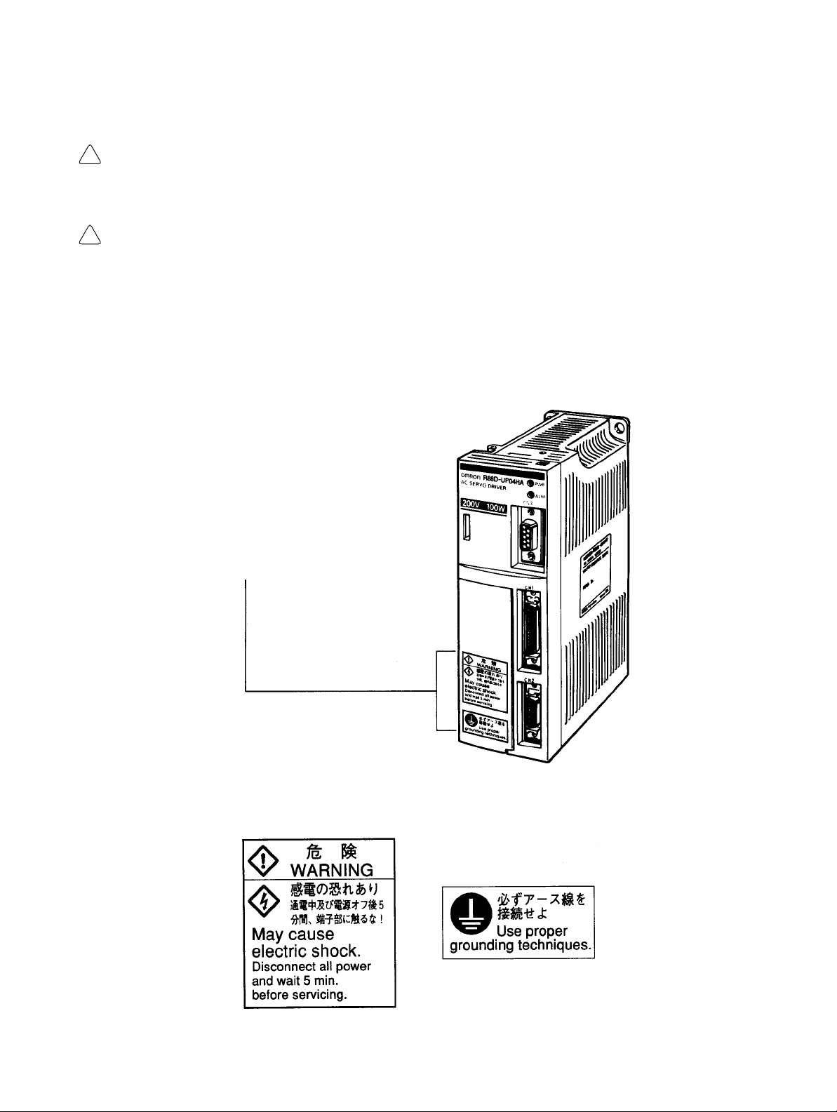
Warning Labels
Warning labels are pasted on the product as shown in the following illustration. Be sure to
follow the instructions given there.
Warning
labels
Warning Labels for Non-conforming Models
Warning
label 1
W
arning label 2
Page 11
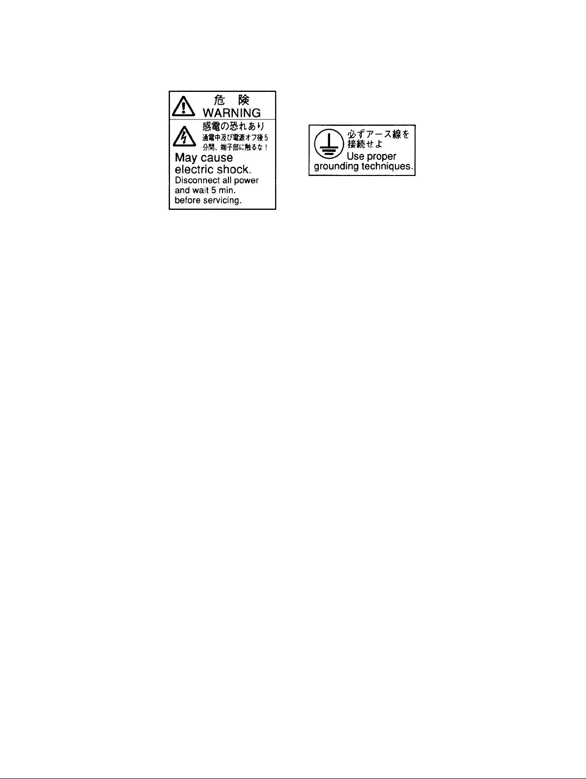
Warning Labels for Models Conforming to EC Directives
W
arning label 2
Warning
label 1
Page 12
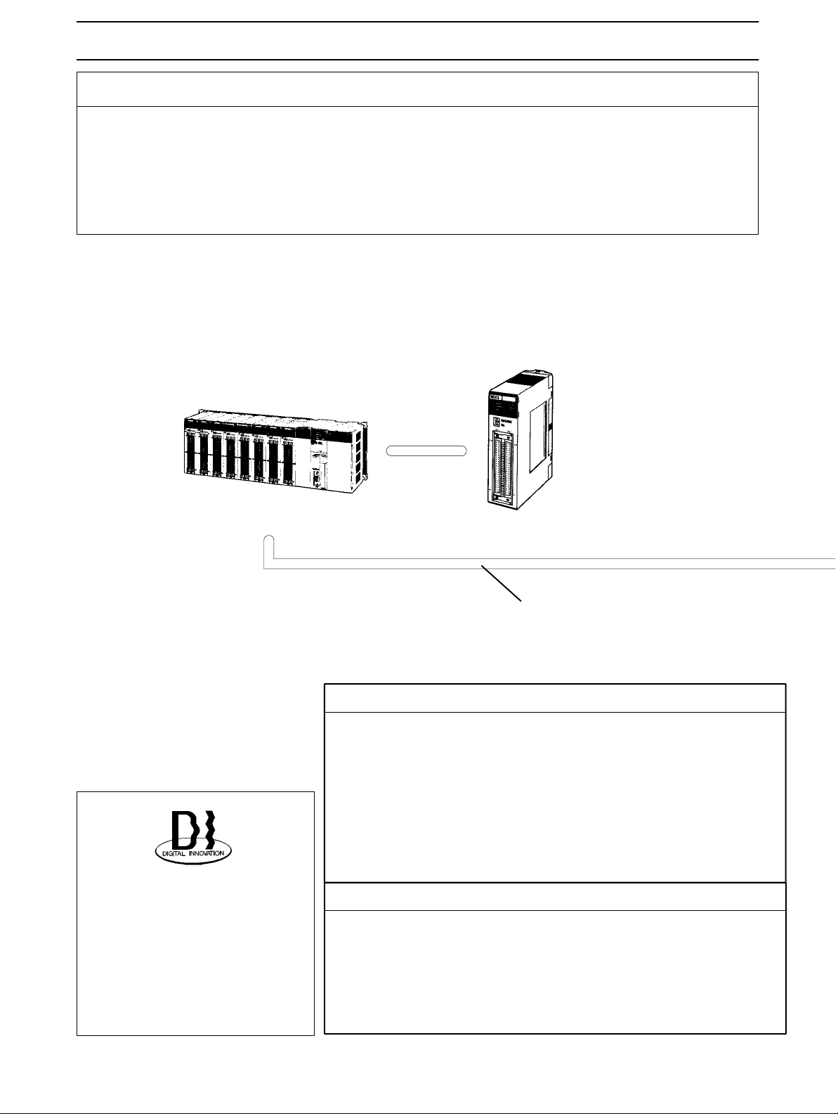
VISUAL INDEX
For users who wish to operate soon.
- The
following portions of
Be
sure you fully understand at least the
tion.
Chapter
ter 3 Operation.
Instructions for jog operation using a Parameter Unit are provided in 3-6.
2 System Design and Installation, and sections
this manual provide the minimum information required for operation.
information in these portions before attempting opera
3-1,
3-2,
3-3,
SYSMAC CS1/C/CV
Programmable Controller
3-4,
3-5, and
3-6 of Chap
Position Control Unit
C200HW-NC113
C200HW-NC213
C200HW-NC413
C200H-NC112
C200H-NC211
C500-NC113
C500-NC211
-
-
OMNUC U is a series of fully
software-controlled AC servo
drivers
built on advanced
OM
RON software servo technology. It provides high performance, a sensitive man-machine
interface, and economy
Controller Connecting Cable
Chapter 5: 5-3-1
Setting Functions
- Setting User Parameters: Section 3-5-1
- Internally Set Speed Control: Section 3-5-3
- Electronic Gears: Section 3-5-4
- Encoder Dividing: Section 3-5-5
- Bias: Section 3-5-6
- Torque Control: Section 3-5-7
- Brake Interlock: Section 3-5-8
Adjustments and Troubleshooting
- Adjustments: Section 3-7
-
- Displays: Section 4-1
- Monitor Outputs: Section 4-2
- Protections and Diagnostics: Section 4-3
- Troubleshooting: Section 4-4
.
Pulse input
Page 13
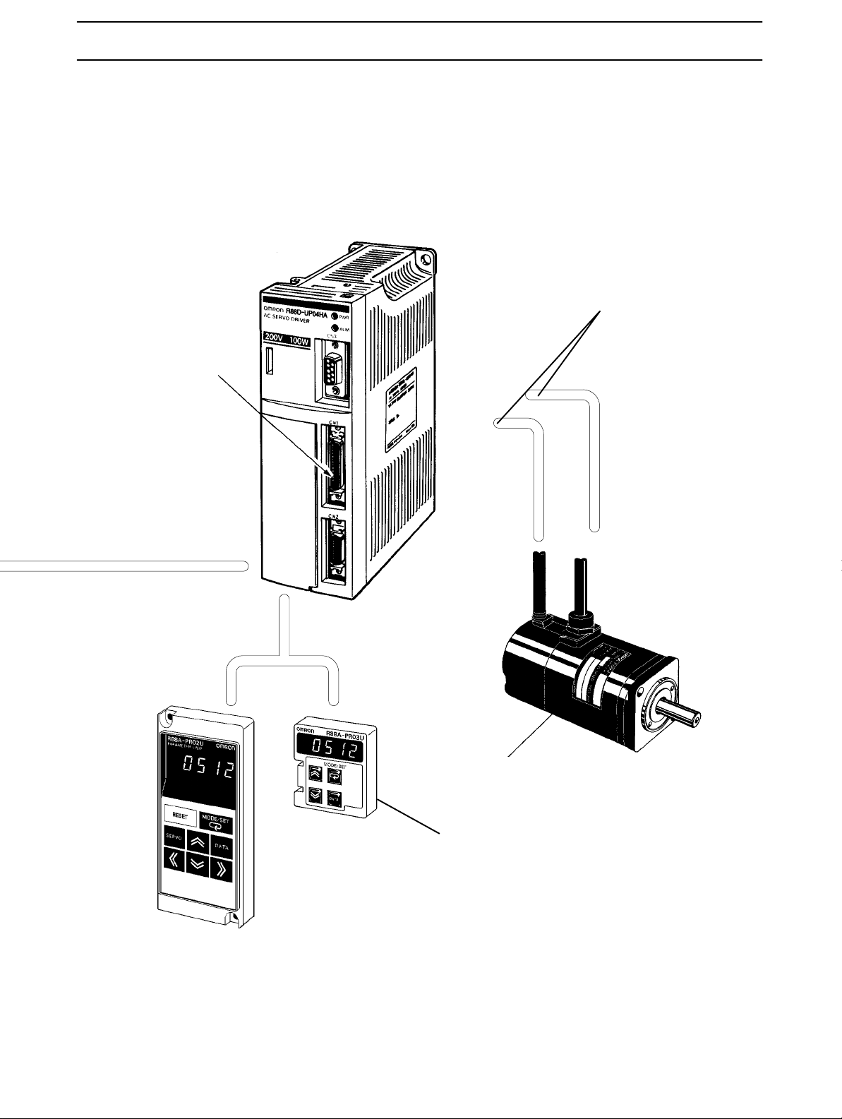
I/O Operations
Chapter 5: 5-1-3
OMNUC U Series
OMNUC U-series AC Servo Driver
Encoder
signals
Cable Specifications
Chapter 5: 5-3-2, 5-3-3
Power
signals
Parameter Units
OMNUC U-series
AC Servomotor
Motor Specifications
Chapter 5: 5-2
Operation Method
Chapter 3: 3-3, 3-4, 3-5
Page 14

Table of Contents
Chapter 1. Introduction .
1-1 Features . . . . . . . . . . . . . . . . . . . . . . . . . . . . . . . . . . . . . . . . . . . . . . . . . . . . . . . . . . . . . . . . . . .
1-2 System Configuration . . . . . . . . . . . . . . . . . . . . . . . . . . . . . . . . . . . . . . . . . . . . . . . . . . . . . . . .
1-3 Servo Driver Nomenclature . . . . . . . . . . . . . . . . . . . . . . . . . . . . . . . . . . . . . . . . . . . . . . . . . . . .
1-4 Applicable Standards and Models . . . . . . . . . . . . . . . . . . . . . . . . . . . . . . . . . . . . . . . . . . . . . . .
1-4-1 UL/cUL Standards . . . . . . . . . . . . . . . . . . . . . . . . . . . . . . . . . . . . . . . . . . . . . . . . . . . .
1-4-2 EC Directives . . . . . . . . . . . . . . . . . . . . . . . . . . . . . . . . . . . . . . . . . . . . . . . . . . . . . . . .
Chapter
2-1 Installation . . . . . . . . . . . . . . . . . . . . . . . . . . . . . . . . . . . . . . . . . . . . . . . . . . . . . . . . . . . . . . . . .
2-2 Wiring Products Conforming to UL/cUL
2-3 Wiring Products Conforming to EC Directives . . . . . . . . . . . . . . . . . . . . . . . . . . . . . . . . . . . . .
2. System Design and Installation. . . . . . . . . . . . . . . . . . . . . .
2-1-1 External Dimensions (Unit: mm) . . . . . . . . . . . . . . . . . . . . . . . . . . . . . . . . . . . . . . . . .
2-1-2 Installation Conditions . . . . . . . . . . . . . . . . . . . . . . . . . . . . . . . . . . . . . . . . . . . . . . . . .
and Wiring Products Not Conforming to Any Standards . . . . . . . . . . . . . . . . . . . . . . . . . . . . .
2-2-1 Connecting OMRON Servo Controllers . . . . . . . . . . . . . . . . . . . . . . . . . . . . . . . . . . . .
2-2-2 Connector-Terminal Conversion Unit . . . . . . . . . . . . . . . . . . . . . . . . . . . . . . . . . . . . .
2-2-3 Wiring Servo Drivers . . . . . . . . . . . . . . . . . . . . . . . . . . . . . . . . . . . . . . . . . . . . . . . . . .
2-2-4 Wiring for Noise Resistance . . . . . . . . . . . . . . . . . . . . . . . . . . . . . . . . . . . . . . . . . . . . .
2-2-5 Peripheral Device Connection Examples . . . . . . . . . . . . . . . . . . . . . . . . . . . . . . . . . . .
2-3-1 Connecting Servo Controllers . . . . . . . . . . . . . . . . . . . . . . . . . . . . . . . . . . . . . . . . . . . .
2-3-2 Wiring Servo Drivers . . . . . . . . . . . . . . . . . . . . . . . . . . . . . . . . . . . . . . . . . . . . . . . . . .
2-3-3 Wiring Products Conforming to EMC Directives . . . . . . . . . . . . . . . . . . . . . . . . . . . .
2-3-4 Peripheral Device Connection Examples . . . . . . . . . . . . . . . . . . . . . . . . . . . . . . . . . . .
. . . . . . . . . . . . . . . . . . . . . . . . . . . . . . . . . . . .
Chapter
3-1 Operational Procedure . . . . . . . . . . . . . . . . . . . . . . . . . . . . . . . . . . . . . . . . . . . . . . . . . . . . . . . .
3-2 Turning On Power and Checking Displays . . . . . . . . . . . . . . . . . . . . . . . . . . . . . . . . . . . . . . . .
3-3 Using Parameter Units . . . . . . . . . . . . . . . . . . . . . . . . . . . . . . . . . . . . . . . . . . . . . . . . . . . . . . . .
3-4 Initial Settings: Setup Parameters . . . . . . . . . . . . . . . . . . . . . . . . . . . . . . . . . . . . . . . . . . . . . . .
3-5 Setting Functions: User Parameters . . . . . . . . . . . . . . . . . . . . . . . . . . . . . . . . . . . . . . . . . . . . . .
3-6 Trial Operation . . . . . . . . . . . . . . . . . . . . . . . . . . . . . . . . . . . . . . . . . . . . . . . . . . . . . . . . . . . . . .
3. Operation. . . . . . . . . . . . . . . . . . . . . . . . . . . . . . . . . . . . . . .
3-2-1 Items to Check Before Turning On Power . . . . . . . . . . . . . . . . . . . . . . . . . . . . . . . . . .
3-2-2 Turning On Power and Confirming the Display . . . . . . . . . . . . . . . . . . . . . . . . . . . . .
3-3-1 Parameter Unit Keys and Functions . . . . . . . . . . . . . . . . . . . . . . . . . . . . . . . . . . . . . . .
3-3-2 Modes and Changing Modes . . . . . . . . . . . . . . . . . . . . . . . . . . . . . . . . . . . . . . . . . . . .
3-3-3 Mode Changes and Display Contents . . . . . . . . . . . . . . . . . . . . . . . . . . . . . . . . . . . . . .
3-4-1 Setting and Checking Setup Parameters (Cn-01, 02) . . . . . . . . . . . . . . . . . . . . . . . . . .
3-4-2 Setup Parameter Contents . . . . . . . . . . . . . . . . . . . . . . . . . . . . . . . . . . . . . . . . . . . . . . .
3-4-3 Important Setup Parameters (Cn-01 and Cn-02) . . . . . . . . . . . . . . . . . . . . . . . . . . . . .
3-5-1 Setting and Checking User Parameters (Cn-04 to 29) . . . . . . . . . . . . . . . . . . . . . . . . .
3-5-2 User Parameter Chart . . . . . . . . . . . . . . . . . . . . . . . . . . . . . . . . . . . . . . . . . . . . . . . . . .
3-5-3 Internal Speed Control Settings . . . . . . . . . . . . . . . . . . . . . . . . . . . . . . . . . . . . . . . . . .
3-5-4 Electronic Gear Function: Position Control . . . . . . . . . . . . . . . . . . . . . . . . . . . . . . . . .
3-5-5 Encoder Dividing Function . . . . . . . . . . . . . . . . . . . . . . . . . . . . . . . . . . . . . . . . . . . . . .
3-5-6 Bias Function: Position Control . . . . . . . . . . . . . . . . . . . . . . . . . . . . . . . . . . . . . . . . . .
3-5-7 Torque Limit Function . . . . . . . . . . . . . . . . . . . . . . . . . . . . . . . . . . . . . . . . . . . . . . . . .
3-5-8 Brake Interlock (For Motors with Brakes) . . . . . . . . . . . . . . . . . . . . . . . . . . . . . . . . . .
3-6-1 Preparations for Trial Operation . . . . . . . . . . . . . . . . . . . . . . . . . . . . . . . . . . . . . . . . . .
3-6-2 Jog Operations . . . . . . . . . . . . . . . . . . . . . . . . . . . . . . . . . . . . . . . . . . . . . . . . . . . . . . .
Page 15

Table of Contents
3-7 Making Adjustments . . . . . . . . . . . . . . . . . . . . . . . . . . . . . . . . . . . . . . . . . . . . . . . . . . . . . . . . .
3-7-1 Auto-tuning . . . . . . . . . . . . . . . . . . . . . . . . . . . . . . . . . . . . . . . . . . . . . . . . . . . . . . . . . .
3-7-2 Manually Adjusting Gain . . . . . . . . . . . . . . . . . . . . . . . . . . . . . . . . . . . . . . . . . . . . . . .
3-8 Regenerative Energy Absorption . . . . . . . . . . . . . . . . . . . . . . . . . . . . . . . . . . . . . . . . . . . . . . . .
3-8-1 Calculating Regenerative Energy . . . . . . . . . . . . . . . . . . . . . . . . . . . . . . . . . . . . . . . . .
3-8-2 Servo Driver Absorbable Regenerative Energy . . . . . . . . . . . . . . . . . . . . . . . . . . . . . .
3-8-3 Absorption of Regenerative Energy with the External Regeneration Resistor
(Models Conforming to UL/cUL Standards
and Models Not Conforming to Any Standards) . . . . . . . . . . . . . . . . . . . . . . . . . . . . .
3-8-4 Processing Regenerative Energy with Multiple Axes
(Models Conforming to EC Directives) . . . . . . . . . . . . . . . . . . . . . . . . . . . . . . . . . . . .
Chapter
4-1 Using Displays . . . . . . . . . . . . . . . . . . . . . . . . . . . . . . . . . . . . . . . . . . . . . . . . . . . . . . . . . . . . . .
4-2 Using the Monitor Output . . . . . . . . . . . . . . . . . . . . . . . . . . . . . . . . . . . . . . . . . . . . . . . . . . . . .
4-3 Protective and Diagnostic Functions . . . . . . . . . . . . . . . . . . . . . . . . . . . . . . . . . . . . . . . . . . . . .
4-4 Troubleshooting . . . . . . . . . . . . . . . . . . . . . . . . . . . . . . . . . . . . . . . . . . . . . . . . . . . . . . . . . . . . .
4-5 Periodic Maintenance . . . . . . . . . . . . . . . . . . . . . . . . . . . . . . . . . . . . . . . . . . . . . . . . . . . . . . . .
Chapter
5-1 Servo Driver Specifications . . . . . . . . . . . . . . . . . . . . . . . . . . . . . . . . . . . . . . . . . . . . . . . . . . . .
5-2 Servomotor Specifications . . . . . . . . . . . . . . . . . . . . . . . . . . . . . . . . . . . . . . . . . . . . . . . . . . . . .
5-3 Cable Specifications . . . . . . . . . . . . . . . . . . . . . . . . . . . . . . . . . . . . . . . . . . . . . . . . . . . . . . . . .
5-4 Parameter Unit Specifications . . . . . . . . . . . . . . . . . . . . . . . . . . . . . . . . . . . . . . . . . . . . . . . . . .
5-5 Regeneration Unit Specifications . . . . . . . . . . . . . . . . . . . . . . . . . . . . . . . . . . . . . . . . . . . . . . .
5-6 Front-surface Mounting Bracket Specifications . . . . . . . . . . . . . . . . . . . . . . . . . . . . . . . . . . . .
4. Application. . . . . . . . . . . . . . . . . . . . . . . . . . . . . . . . . . . . . .
4-1-1 Display Functions . . . . . . . . . . . . . . . . . . . . . . . . . . . . . . . . . . . . . . . . . . . . . . . . . . . . .
4-1-2 Status Display Mode . . . . . . . . . . . . . . . . . . . . . . . . . . . . . . . . . . . . . . . . . . . . . . . . . . .
4-1-3 Monitor Mode (Un-) . . . . . . . . . . . . . . . . . . . . . . . . . . . . . . . . . . . . . . . . . . . . . . . . . . .
4-1-4 Checking Servomotor Parameters (Cn-00 Set to 04) . . . . . . . . . . . . . . . . . . . . . . . . . .
4-3-1 Alarm Displays and Alarm Code Outputs . . . . . . . . . . . . . . . . . . . . . . . . . . . . . . . . . .
4-3-2 Alarm Output . . . . . . . . . . . . . . . . . . . . . . . . . . . . . . . . . . . . . . . . . . . . . . . . . . . . . . . .
4-3-3 Overload Characteristics (Electron Thermal Characteristics) . . . . . . . . . . . . . . . . . . .
4-3-4 Alarm History Display Mode . . . . . . . . . . . . . . . . . . . . . . . . . . . . . . . . . . . . . . . . . . . .
5. Specifications. . . . . . . . . . . . . . . . . . . . . . . . . . . . . . . . . . . .
5-1-1 General Specifications . . . . . . . . . . . . . . . . . . . . . . . . . . . . . . . . . . . . . . . . . . . . . . . . .
5-1-2 Performance Specifications . . . . . . . . . . . . . . . . . . . . . . . . . . . . . . . . . . . . . . . . . . . . .
5-1-3 I/O Specifications . . . . . . . . . . . . . . . . . . . . . . . . . . . . . . . . . . . . . . . . . . . . . . . . . . . . .
5-1-4 Explanation of User Parameters . . . . . . . . . . . . . . . . . . . . . . . . . . . . . . . . . . . . . . . . . .
5-2-1 General Specifications . . . . . . . . . . . . . . . . . . . . . . . . . . . . . . . . . . . . . . . . . . . . . . . . .
5-2-2 Performance Specifications . . . . . . . . . . . . . . . . . . . . . . . . . . . . . . . . . . . . . . . . . . . . .
5-2-3 Torque and Rotational Speed Characteristics . . . . . . . . . . . . . . . . . . . . . . . . . . . . . . . .
5-2-4 Allowable Loads on Servomotor Shafts . . . . . . . . . . . . . . . . . . . . . . . . . . . . . . . . . . . .
5-2-5 Encoder Specifications . . . . . . . . . . . . . . . . . . . . . . . . . . . . . . . . . . . . . . . . . . . . . . . . .
5-3-1 Controller Connecting Cables . . . . . . . . . . . . . . . . . . . . . . . . . . . . . . . . . . . . . . . . . . .
5-3-2 Encoder Cables . . . . . . . . . . . . . . . . . . . . . . . . . . . . . . . . . . . . . . . . . . . . . . . . . . . . . . .
5-3-3 Power Cable . . . . . . . . . . . . . . . . . . . . . . . . . . . . . . . . . . . . . . . . . . . . . . . . . . . . . . . . .
Chapter
6-1 Connection Examples . . . . . . . . . . . . . . . . . . . . . . . . . . . . . . . . . . . . . . . . . . . . . . . . . . . . . . . .
6-2 Servo Connector Terminal Connection Unit . . . . . . . . . . . . . . . . . . . . . . . . . . . . . . . . . . . . . . .
6-3 OMNUC U-series Standard Models . . . . . . . . . . . . . . . . . . . . . . . . . . . . . . . . . . . . . . . . . . . . .
6-4 Parameter Setting Forms . . . . . . . . . . . . . . . . . . . . . . . . . . . . . . . . . . . . . . . . . . . . . . . . . . . . . .
6. Supplementary Materials. . . . . . . . . . . . . . . . . . . . . . . . . .
Page 16

1
Chapter 1
Introduction
1-1 Features
1-2 System Configuration
1-3 Servo Driver Nomenclature
1-4 Applicable Standards and Models
Page 17

Introduction Chapter 1
1-1 Features
OMNUC
and perform precision position control. There are 7 types of AC Servomotors: 30-W, 50-W, 100-W,
200-W, 300-W, 400-W, and 750-W.
AC Servo Drivers control the power supplied to AC Servomotors with pulse-train input signals
H Motor Output Capacity
AC Servomotors with the following output capacities are available.
S For 200/230-VAC (170 to 253 V) single-phase, 50/60-Hz Input
30 W, 50 W, 100 W, 200 W, 400 W, and 750 W
S For 100/115-VAC (85 to 127 V) single-phase, 50/60-Hz Input
30 W, 50 W, 100 W, 200 W, and 300 W
The Servomotors also come with and without brakes, and with and without keys on the straight
shaft. Servomotors that conform to EC Directives, however, are available only with keys on the
shaft.
H Models Conforming to UL/cUL Standards Available (UL/cUL Markings)
AC
Servomotors and Servo Drivers that conform to UL/cUL Standards are now available. Their
formance,
els. They are useful for obtaining approvals required for specific applications.
Models
(HA/LA)
functionality
conforming to UL/cUL Standards have the same
models. As shown in the following table, they are distinguished by
, and appearance are the same as the conventional U-series (HA/LA) mod
product names as conventional U-series
the manufacturing date.
per
-
-
Model Manufacturing date Type Remarks
Models not conforming to
any standards
Models conforming to
UL/cUL Standards
Before April 1998
After May 1998 HA/LA UL/cUL markings are
H/L, HA/LA
Production of H/L models
discontinued.
attached to products.
H EC Directives (CE Markings)
AC Servomotors and Servo Drivers that conform to EC low-voltage and EMC directives are now
available.
and will aid in obtaining specifications.
These provide the same performance and functions as the rest of the
U Series (HA/LA),
H Control Functions
Any one of the following 4 control modes can be selected in the parameter settings.
S Position Control (Factory Setting)
Controls
Any one of the following 3 pulse trains can be selected: forward/reverse pulses, feed pulses/
directional signals, or 90_ differential phase (A/B phases) signals.
S Position Control with Pulse Stop Input Enabled (HA/LA/V/W Models)
Turning
during position control.
the position and speed of the Servomotor very precisely with pulse-train input signals.
ON the Pulse Stop Input (IPG) prevents the control signals from being read by the
Unit
1-2
Page 18

Introduction Chapter 1
S Internal Speed Control Settings
The
speed of the motor is controlled with the three speeds (No. 1, No. 2, and No. 3 internal speed
settings) set in the parameters. This mode is effective for simple position control or speedswitching operation.
S Internal Speed Control Setting + Position Control (HA/LA/V/W Models)
Speed
formed with pulse-train inputs.
control can be performed with the internal speed settings and position control can be per
H Auto-tuning
The
gain can be adjusted automatically when the responsiveness has been selected to match the
rigidity of the mechanical system. The auto-tuning feature automatically finds the optimum adjust
ment to match the load, with no need for difficult operations.
H Monitor
Displays the driver’s operating status on the Parameter Unit.
The following items can be monitored: speed feedback, speed commands, torque commands,
number of pulses from the U-phase edge, electrical angle, internal status (bit display), command
pulse’s speed, position deviation, and the input pulse counter.
H Jog Operation
Forward/Reverse
be set in the parameters.
motor operation can be controlled from the Parameter Unit. Rotational speed can
H Electronic Gear Function (Position Control)
The
number of pulses used to rotate the motor is calculated by multiplying the number of command
pulses by the electronic gear ratio. This function is useful in the following kinds of cases.
-
-
S When
S When
S When you want to set the movement/pulse to a certain amount, such as 0.01 mm/pulse
The
The
0.01 to 100, i.e., 0.01 ≤ G1/G2 ≤ 100.
you want to finely adjust the position and speed of two lines that need to be synchronized
you want to increase the control pulse frequency of a controller with a low pulse frequency
electronic gear ratio is set with parameters G1 and G2 (G1=numerator and G2=denominator).
setting range for parameters G1 and G2 is 1 to 65,535. The setting range for the gear ratio is
H Encoder Resolution Function
This
function allows the encoder
pulses/revolution.
signal output from the driver to be set anywhere from 16 to 2,048
H Software Start Function (Internal Speed Control Settings)
This
function causes the motor to be started/stopped in the preset acceleration/deceleration times,
allowing a simple position control system to be constructed without a Positioner or Host Controller
The acceleration and deceleration times are set separately, and the setting range is 0 to 10 s for
each.
.
1-3
Page 19

Introduction Chapter 1
H Pulse Smoothing Function (Position Control)
Even
high-frequency commands
in the command pulses. The same setting is used for
and the setting range is 0 to 64 ms.
H Reverse Mode
Forward/Reverse
motor or encoder.
commands can be switched
H Brake Interlock Output
Outputs
ing brake of a motor with a brake can be operated reliably.
a timing signal interlocked with the motor’s ON/OFF status and rotational speed. The hold
H Overtravel Sequence
An
overtravel sequence compatible with the system can be selected. There are three deceleration
methods
deceleration (parameter setting).
available: dynamic brake deceleration, free-run deceleration, and emergency-stop torque
can be executed smoothly by including acceleration/deceleration
both
the acceleration and deceleration times,
in the parameters, without changing the wiring to the
-
H Feed-forward and Bias Functions (Position Control)
These functions reduce the position control time.
S Feed-forward Function
Reduces
counter.
S Bias Function
Reduces
deviation counter value exceeds the position completion range.
the position control time by reducing the number of pulses accumulated in the
the position control time by adding the bias revolutions to
the speed control when the
deviation
H Computer Monitor Software (HA/LA/V/W Models)
The special Servo Driver Communications Software allows parameter setting, speed and current
monitoring,
puter.
tor the operation of several drivers. Refer to the
(I513)
I/O monitoring, auto-tuning, and jog operations to be performed from
It is also possible to perform multiple-axis communications that set the parameters and moni
Computer Monitor Software Instruction Manual
for OMNUC U-series Servo Drivers for more details.
a personal com
-
-
1-4
Page 20
Introduction Chapter 1
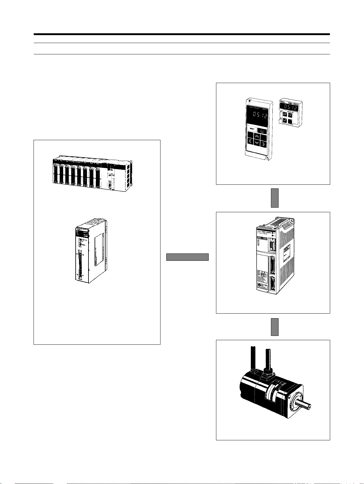
1-2 System Configuration
Parameter Units
SYSMAC CS1/C/CV
Programmable Controller
C200HW-NC113
C200HW-NC213
C200HW-NC413
C200H-NC112
C200H-NC211
C500-NC113
C500-NC211
Position Control Unit
OMNUC U-series
AC Servo Driver
OMNUC U-series
AC Servomotor
1-5
Page 21
Introduction Chapter 1
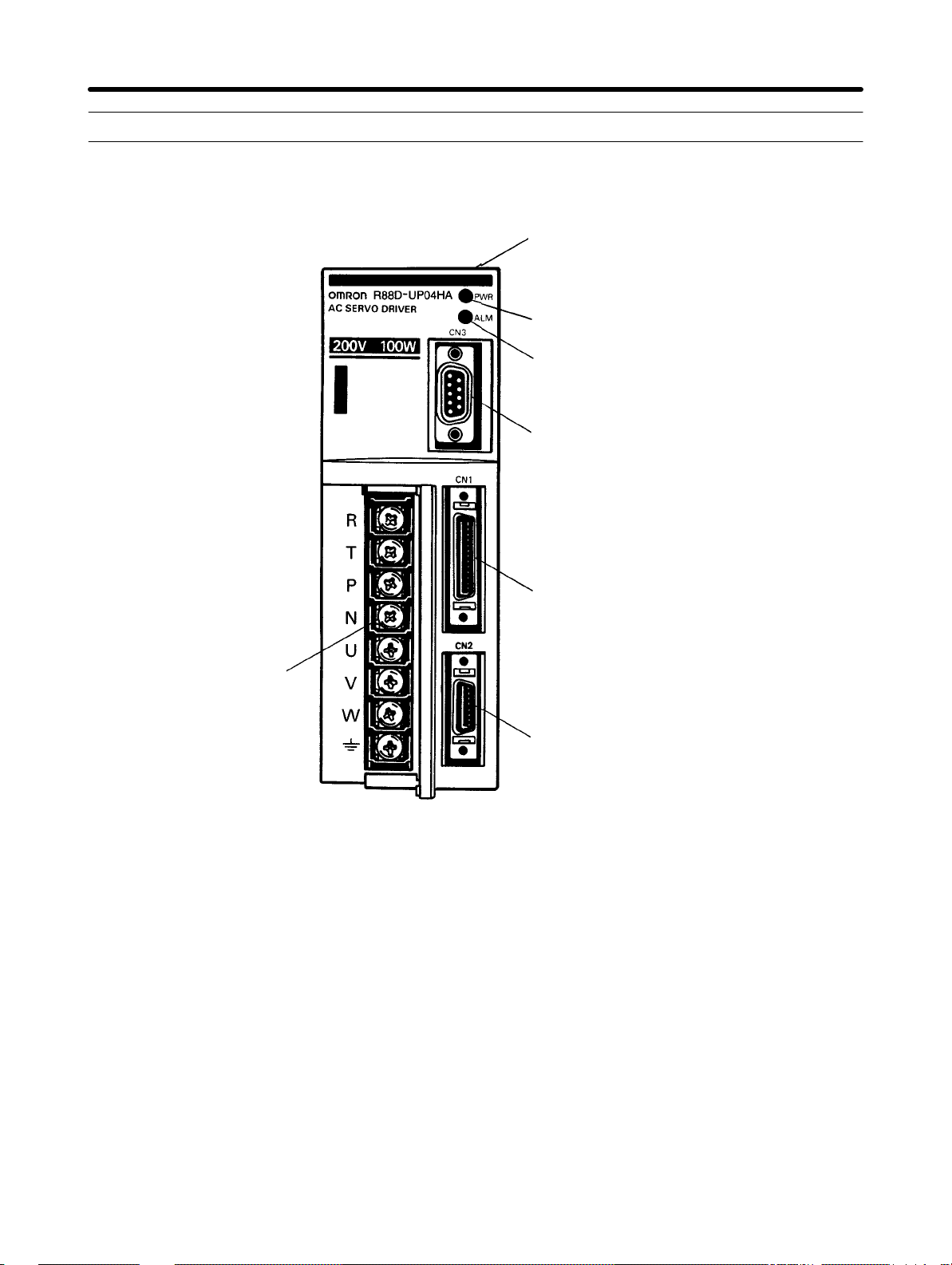
1-3 Servo Driver Nomenclature
H Front View
CN4: Connector for monitor output
Power supply indicator
Alarm indicator
CN3: Parameter Unit connector
Terminal block
CN1: Control I/O connector
CN2: Encoder connector
1-6
Page 22
pp y
Introduction Chapter 1
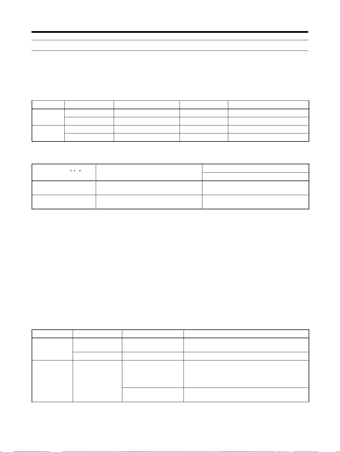
1-4 Applicable Standards and Models
1-4-1 UL/cUL Standards
H Applicable Standards
Standard Product Applicable Standard File No. Remarks
UL
cUL
H Applicable Models
AC Servo Driver UL508C E179149 Power conversion equipment
AC Servomotor UL1004 E179189 Electric motors
AC Servo Driver cUL C22.2 No. 14 E179149 Industrial control equipment
AC Servomotor cUL C22.2 No.100 E179189 Motor and generators
Power supply
200 VAC R88D-UPjjHA
100 VAC R88D-UPjjLA
AC Servo Drivers
(See note 1.)
(See note 1.)
R88M-Ujjj30HA-j
R88M-Ujjj30LA-j
AC Servomotors
With incremental encoder
(See note 2.) (See note 3.)
(See notes 2.) (See note 3.)
Note 1. Maximum output current: for example, “04” means approx. 4 A.
Note 2. Motor capacity: for example, “100” means 100 W.
Note 3. Optional specifications
None: Straight shaft without keys and without brake
B: Straight shaft without keys and with brake
S1: Straight shaft with keys and without brake
BS1: Straight shaft with keys and with brake
Note 4. UL/cUL Standards apply to models manufactured after May 1998.
1-4-2 EC Directives
H Applicable Standards
EC Directive Product Directive Remarks
Low voltage
EMC AC Servo Driver
Note Installation under the conditions specified in
tives
AC Servo Driver EN61010-1 Safety requirements for electrical equipment for
measurement, control, and laboratory use.
AC Servomotor IEC34-1, -5, -8, -9 Rotating electrical machines.
AC Servomotor
EN55011 class A
group 1
EN50082-2 Electromagnetic compatibility generic immunity
Limits and methods of measurement of radio
disturbance characteristics of industrial,
scientific, and medical (ISM) radio-frequency
equipment.
standard, Part 2 Industrial environment.
2-3-3 Wiring Products Conforming to EMC Direc-
is required to conform to EMC Directives.
1-7
Page 23

pp y
Introduction Chapter 1
H Applicable Models
Power supply
200 VAC R88D-UPjjV R88M-Ujjj30VA-j
100 VAC R88D-UPjjW R88M-Ujjj30WA-j
Note Optional specifications (shaft profile: straight shaft with keys)
S1: Straight shaft with keys and without brake
BS1: Straight shaft with keys and with brake
AC Servo Drivers
AC Servomotors
With incremental encoder
(See note.)
(See note.)
1-8
Page 24
2
Chapter 2
System Design and Installation
2-1 Installation
2-2 Wiring Products Conforming to UL/cUL
and Wiring Products Not Conforming to Any
Standards
2-3 Wiring Products Conforming to EC Directives
Page 25

System Design and Installation
Installation and Wiring Precautions
!
Caution Do
not step on or place a
heavy object on the product. Doing so may result in injury
Chapter 2
.
!
Caution Do
!
Caution Be
!
Caution Provide
!
Caution Do not apply any strong impact. Doing so may result in malfunction.
!
Caution Be sure to wire correctly and securely. Not doing so may result in motor runaway,
!
Caution Be
!
Caution Use
!
Caution Always use the power supply voltage specified in the User’s Manual. An incorrect
not cover the inlet or outlet ports and prevent any foreign objects from entering
the product. Doing so may result in fire.
sure to install the product in the correct direction. Not doing so may result in mal
function.
the specified clearances between the
with other devices. Not doing so may result in fire or malfunction.
injury, or malfunction.
sure that all the mounting screws, terminal screws, and cable connector screws
are tightened to the torque specified in the relevant manuals. Incorrect tightening
torque may result in malfunction.
crimp terminals for wiring. Do not connect bare stranded wires directly to termi
nals. Connection of bare stranded wires may result in burning.
voltage may result in malfunction or burning.
Servo Driver and the control panel or
-
-
!
Caution Take
!
Caution Install
!
Caution Provide an appropriate stopping device on the machine side to secure safety. (A
!
Caution Provide
!
Caution Take
appropriate measures to ensure that the specified power with the rated voltage
and
frequency is supplied. Be particularly careful in places where the power supply
is unstable. An incorrect power supply may result in malfunction.
external breakers and take other safety measures
external wiring. Insufficient safety measures against short-circuiting may result in
burning.
holding
injury.
operation and power interruption. Not doing so may result in injury.
lowing locations:
S Locations subject to static electricity or other forms of noise.
S Locations subject to strong electromagnetic fields and magnetic fields.
S Locations subject to possible exposure to radioactivity.
S Locations close to power supplies.
brake is
an external emergency stopping device that
appropriate and suf
not a stopping device for securing safety
ficient countermeasures when installing systems in the fol
against short-circuiting in
.) Not doing so may result in
allows an instantaneous stop of
-
2-2
Page 26
System Design and Installation
2-1 Installation
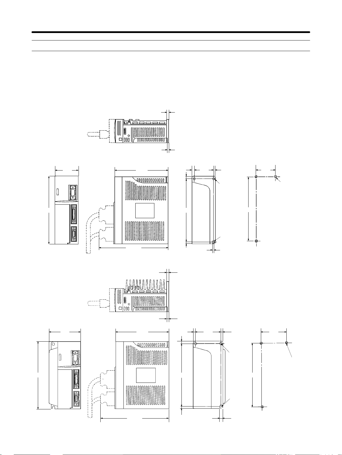
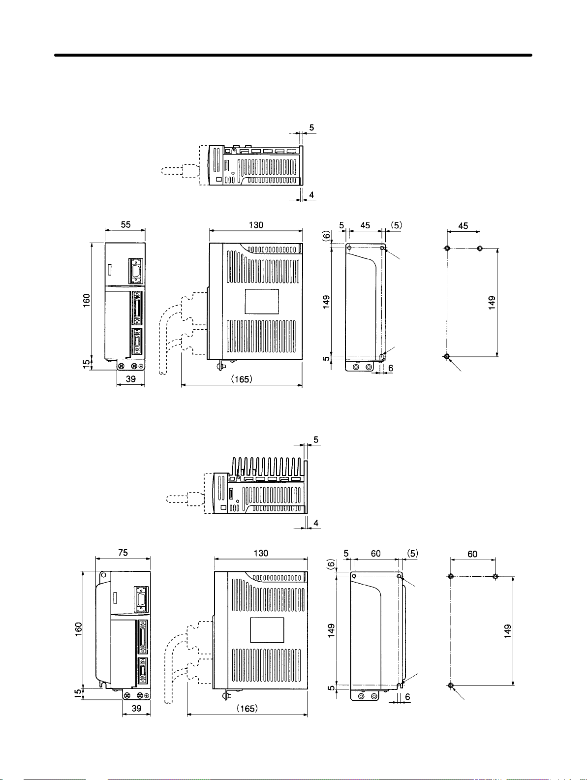
2-1-1 External Dimensions (Unit: mm)
H AC Servo Drivers Conforming to UL/cUL Standards and AC
Servomotors Not Conforming to Any Standards
D R88D-UP02H(A)/UP03H(A)/UP04H(A)/UP08H(A) (200 VAC, 30 to 200 W)
R88D-UP03L(A)/UP04L(A)/UP10L(A) (100 VAC, 30 to 100 W)
5
Chapter 2
160
55 130
(165)
4
5
(6)
149
5
45 (5) 45
Two,
6 dia.
R3
6
Installation dimensions
149
D R88D-UP12H(A) (200 VAC, 400 W) and R88D-UP12L(A) (100 VAC, 200 W)
5
Three, M4
160
4
75 130 60 (5)
(165)
(6)
149
5
5
Two,
6 dia.
R3
6
Installation dimensions
60
Three, M4
149
2-3
Page 27

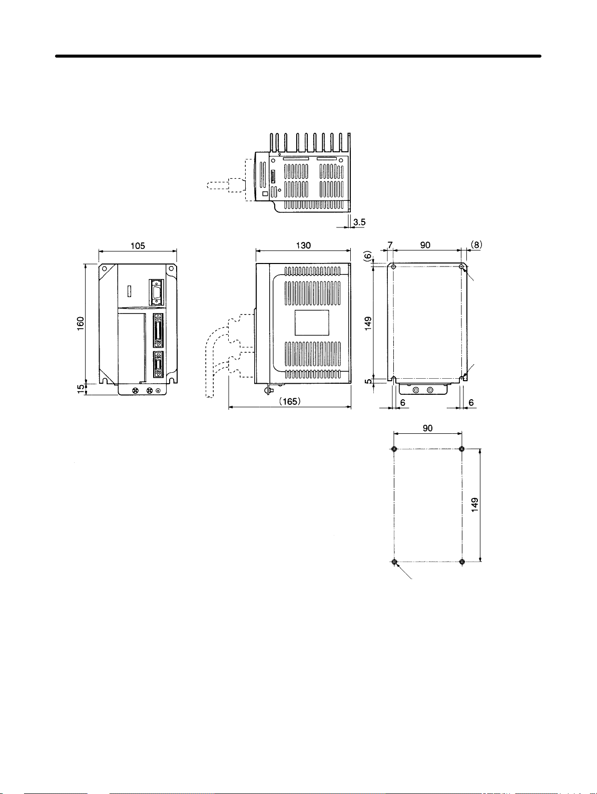
System Design and Installation
H AC Servo Drivers Conforming to UL/cUL Standards and AC
Servomotors Not Conforming to Any Standards (Contd.)
D R88D-UP20H(A) (200 VAC, 750 W) and R88D-UP15LA (100 VAC, 300 W)
3.5
7
105 130 90
6
(8)
Two, 6 dia.
Chapter 2
160
(165)
Installation
dimensions
149
Two, R3
5
66
90
Four, M4
149
2-4
Page 28
System Design and Installation
H AC Servo Drivers Conforming to EC Directives
D R88D-UP02V/UP03V/UP04V/UP08V (200 VAC, 30 to 200 W)
R88D-UP03W/UP04W/UP10W (100 VAC, 30 to 100 W)
Two,
Chapter 2
Installation
dimensions
6 dia.
D R88D-UP12V (200 VAC, 400 W)
R88D-UP12W (100 VAC, 200 W)
R3
Two,
Three, M4
Installation
dimensions
6 dia.
R3
Three, M4
2-5
Page 29
System Design and Installation
H AC Servo Drivers Conforming to EC Directives (Contd.)
D R88D-UP20V (200 VAC, 750 W)
R88D-UP15W (100 VAC, 300 W)
Chapter 2
Two,
6 dia.
Installation
dimensions
Two, R3
Four, M4
2-6
Page 30
System Design and Installation
H Regeneration Unit
D R88A-RG08UA
160
(15)
130 149
15
(6)
25
5
25
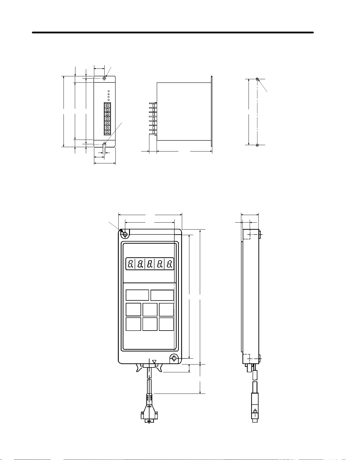
H Parameter Units
50
6
Dia.:
R3
(18.5) 130
6
Chapter 2
Installation dimensions
Two, M4
149
D R88A-PR02U
Two,
4.5 dia.
63
50
(8)
125
18.5
7
135
1000
2-7
Page 31

System Design and Installation
D R88A-PR03U
54
57.5
15
Chapter 2
6.9
2-8
Page 32

System Design and Installation
H AC Servomotors Conforming to UL/cUL Standards and AC
Servomotors Not Conforming to Any Standards
D 30-W/50-W/100-W Standard Models:
R88M-U03030HA, R88M-U05030HA, R88M-U10030HA
R88M-U03030LA, R88M-U05030LA, R88M-U10030LA
300±30
6.5 4
17
35
300±30
5
9.5
2.5
Encoder adapter
Motor plug
6h6 dia.
30h7 dia.
Two,
4.3 dia.
46
dia.
18
14
dia.
6
Four, R3.7
40
Chapter 2
33
LL 25
L
D 30-W/50-W/100-W Models with Brake:
R88M-U03030HA-B, R88M-U05030HA-B, R88M-U10030HA-B
R88M-U03030LA-B, R88M-U05030LA-B, R88M-U10030LA-B
300±30
6.5
35
300±30
9.5
2.55
17
33 LB
25LL
L
Encoder adapter
Motor plug
Two,
4.3 dia.
6h6 dia.
30h7 dia.
46
dia.
40
21
14
dia.
4
40
Four, R3.7
40
Standard Models
Model L LL S
R88M-U03030HA
94.5 69.5 6
R88M-U03030LA
R88M-U05030HA
102.0 77.0 6
R88M-U05030LA
R88M-U10030HA
119.5 94.5 8
R88M-U10030LA
Models with Brake
Model L LL LB S
R88M-U03030HA-B
R88M-U03030LA-B
R88M-U05030HA-B
R88M-U05030LA-B
R88M-U10030HA-B
R88M-U10030LA-B
126 101 31.5 6
133.5 108.5 31.5 6
160 135 40.5 8
2-9
Page 33

System Design and Installation
H AC Servomotors Conforming to UL/cUL Standards and AC
Servomotors Not Conforming to Any Standards (Contd.)
D 200-W/300-W/400-W Standard Models:
R88M-U20030HA, R88M-U40030HA
R88M-U20030LA, R88M-U30030LA
300±30
5.2 7
35
300±30
12
17
63
Encoder adapter
Motor plug
Four,
5.5 dia.
14h6 dia.
70
dia.
50h7 dia.
21
14
dia.
Four, R5.3
60
Chapter 2
34
LL 30
L
D 200-W/300-W/400-W Models with Brake:
R88M-U20030HA-B, R88M-U40030HA-B
R88M-U20030LA-B, R88M-U30030LA-B
300±30
35
5.2 5.5 7
17
34 39.5
LL 30
L
300±30
12
63
60
Encoder adapter
Motor plug
14
Four,
5.5
dia.
14h6 dia.
70 dia.
50h7 dia.
21
dia.
Four, R5.3
60
60
Model L LL
R88M-U20030HA
R88M-U20030LA
R88M-U40030HA
R88M-U30030LA
2-10
Standard Models
126.5 96.5
154.5 124.5
Models with Brake
Model L LL
R88M-U20030HA-B
R88M-U20030LA-B
R88M-U40030HA-B
R88M-U30030LA-B
166 136
194 164
Page 34

System Design and Installation
H AC Servomotors Conforming to UL/cUL Standards and AC
Servomotors Not Conforming to Any Standards (Contd.)
D 750-W Standard Models: R88M-U75030HA
300±30
35
85.2
17
300±30
15
83
Encoder adapter
Motor plug
Four,
7 dia.
21
14 dia.
Chapter 2
Four, R8.2
16h6 dia.
35
34
145 40
185
D 750-W Models with Brake: R88M-U75030HA-B
300±30
35
85.2
17
300±30
15
83
90 dia.
70h7 dia.
Encoder adapter
Motor plug
Four,
7 dia.
80
80
21
14 dia.
Four, R8.2
34 44.5
189.5 40
229.5
16h6 dia.
35
90 dia.
80
70h7 dia.
80
2-11
Page 35

System Design and Installation
H AC Servomotors Conforming to EC Directives
D 30-W/50-W/100-W Standard Models:
R88M-U03030VA-S1, R88M-U05030VA-S1, R88M-U10030VA-S1
R88M-U03030WA-S1, R88M-U05030WA-S1, R88M-U10030WA-S1
14
dia.
Chapter 2
Sh6 dia.
Two, 4.3 dia.
46 dia.
30h7 dia.
Four, R3.7
D 30-W/50-W/100-W Models with Brake:
R88M-U03030VA-BS1, R88M-U05030VA-BS1, R88M-U10030VA-BS1
R88M-U03030WA-BS1, R88M-U05030WA-BS1, R88M-U10030WA-BS1
14
dia.
Sh6 dia.
Two, 4.3 dia.
46 dia.
30h7 dia.
Four, R3.7
Model L LL S
R88M-U03030VA-S1
R88M-U03030WA-S1
R88M-U05030VA-S1
R88M-U05030WA-S1
R88M-U10030VA-S1
R88M-U10030WA-S1
2-12
Standard Models
94.5 69.5 6
102.0 77.0 6
119.5 94.5 8
Models with Brake
Model L LL LB S
R88M-U03030VA-BS1
R88M-U03030WA-BS1
R88M-U05030VA-BS1
R88M-U05030WA-BS1
R88M-U10030VA-BS1
R88M-U10030WA-BS1
126 101 31.5 6
133.5 108.5 31.5 6
160 135 40.5 8
Page 36

System Design and Installation
Chapter 2
H AC Servomotors Conforming to EC Directives (Contd.)
D 200-W/300-W/400-W Standard Models: R88M-U20030VA-S1, R88M-U40030VA-S1
R88M-U20030WA-S1, R88M-U30030WA-S1
14
dia.
Four,
14h6 dia.
50h7 dia.
5.5 dia.
70 dia.
Four, R5.3
D 200-W/300-W/400-W Models with Brake: R88M-U20030VA-BS1,
R88M-U40030VA-BS1, R88M-U20030WA-BS1, R88M-U30030WA-BS1
14
dia.
Four,
14h6 dia.
50h7 dia.
5.5 dia.
70 dia.
Four, R5.3
Standard Models Standard Models
Model L LL
R88M-U20030VA-S1
R88M-U20030WA-S1
R88M-U40030VA-S1
R88M-U30030-WA-S1
126.5 96.5
154.5 124.5
Models with Brake
Model L LL
R88M-U20030VA-BS1
R88M-U20030WA-BS1
R88M-U40030VA-BS1
R88M-U30030WA-BS1
166 136
194 164
2-13
Page 37

System Design and Installation
H AC Servomotors Conforming to EC Directives (Contd.)
D 750-W Standard Models: R88M-U75030VA-S1
14
dia.
Chapter 2
16h6 dia.
D 750-W Models with Brake: R88M-U75030VA-BS1
70h7
Four
90 dia.
dia.
, 7 dia.
Four, R8.2
2-14
16h6 dia.
70h7
90 dia.
dia.
Four
, 7 dia.
14
dia.
Four, R8.2
Page 38

System Design and Installation
H Shaft Dimensions of Motors With Keys
Standard
(produced
model number. Key slots are based on JIS B1301-1976.
D 30-W/50-W Models
Without Brake: R88M-U03030jj-S1, R88M-U05030jj-S1
With Brake: R88M-U03030jj-BS1, R88M-U05030jj-BS1
D 100-W Models
Without Brake: R88M-U10030jj-S1
With Brake: R88M-U10030jj-BS1
U-series AC Servomotors do not have keys on the shafts. The dimensions of motors with keys
on order) are shown below
. Motors with keys are
Dia.:
Dia.:
6h6
8h6
2
2
14
14
indicated by adding “-S1” to the end of the
1.2
1.8
3
Chapter 2
3
D 200-W/300-W/400-W Models
Without Brake: R88M-U20030jj-S1, R88M-U40030jj-S1, R88M-U30030jj-S1
With Brake: R88M-U20030jj-BS1, R88M-U40030jj-BS1, R88M-U30030jj-BS1,
20
Dia.:
14h6
5
3
5
D 750-W Models
Without Brake: R88M-U75030jj-S1,
With Brake: R88M-U75030jj-BS1
30
Dia.:
16h6
3
5
5
2-15
Page 39

É
É
É
É
É
É
É
É
É
É
É
System Design and Installation
Chapter 2
2-1-2 Installation Conditions
H AC Servo Drivers
D Space Around Drivers
• Install
• Mount the Servo Drivers vertically (so that the model number and writing can be read).
Servo Drivers according to the dimensions shown in the following illustration to ensure proper
heat
dispersion
and convection inside the panel. Also install a fan for circulation if Servo Drivers are
installed side by side to prevent uneven temperatures from developing inside the panel.
ЙЙЙЙЙЙЙЙЙЙЙЙЙЙЙЙЙЙЙЙ
50
ЙЙЙЙЙЙЙЙЙЙЙЙЙЙЙЙЙЙЙЙ
ЙЙЙЙЙЙЙЙЙЙЙЙЙЙЙЙЙЙЙЙ
ЙЙЙЙЙЙЙЙЙЙЙЙЙЙЙЙЙЙЙЙ
ЙЙЙЙЙЙЙЙЙЙЙЙЙЙЙЙЙЙЙЙ
ЙЙЙЙЙЙЙЙЙЙЙЙЙЙЙЙЙЙЙЙ
ЙЙЙЙЙЙЙЙЙЙЙЙЙЙЙЙЙЙЙЙ
ЙЙЙЙЙЙЙЙЙЙЙЙЙЙЙЙЙЙЙЙ
ЙЙЙЙЙЙЙЙЙЙЙЙЙЙЙЙЙЙЙЙ
ЙЙЙЙЙЙЙЙЙЙЙЙЙЙЙЙЙЙЙЙ
30 mm min.
ЙЙЙЙЙЙЙЙЙЙЙЙЙЙЙЙЙЙЙЙ
Fan Fan
Servo Driver
W
W = 10 mm min.
Servo Driver
Servo Driver
W
mm min.
50 mm min.
Side
of
Unit
D Operating Environment
Be sure that the environment in which Servo Drivers are operated meets the following conditions.
• Ambient operating temperature: 0°C to +55°C
• Ambient operating humidity: 35% to 85% (RH, with no condensation)
• Atmosphere: No corrosive gases.
D Ambient Temperature
• Servo Drivers should be operated in environments in which there is minimal temperature rise to
maintain a high level of reliability.
• Temperature
temperature
ent temperature of the Servo Driver from exceeding 55°C.
• Unit
surface temperatures
resistant materials for wiring, and keep separate any devices or wiring that are sensitive to heat.
service life of a Servo Driver is largely determined by the temperature around the internal elec
• The
trolytic
ume
due
capacitors. The service life of an electrolytic capacitor is af
and an increase in internal resistance, which can result in overvoltage alarms, malfunctioning
to noise, and damage to individual elements. If a Servo Driver is
mum ambient temperature of 55°C, then a service life of approximately 50,000 hours can be expected. A drop of 10°C in the ambient temperature will double the expected service life.
2-16
rise in any Unit installed in a closed space, such as a control box, will cause the ambient
to rise inside the entire closed space. Use a fan or a air conditioner to prevent the ambi
may rise to as much as 30°C above the ambient temperature. Use heat-
fected by a drop in electrolytic vol
always operated at the maxi
-
-
-
-
Page 40

System Design and Installation
Chapter 2
D Keeping Foreign Objects Out of Units
• Place
a cover over the Units or take other preventative measures to prevent foreign objects, such as
drill
filings, from getting into the Units during installation. Be sure to
tion is complete. If the cover is left on during operation, heat buildup may damage the Units.
remove the cover after installa
-
• Take
measures during installation and operation to
oil, machining oil, dust, or water from getting inside of Servo Drivers.
prevent foreign objects such as metal particles,
H AC Servomotors
D Operating Environment
Be sure that the environment in which the Servomotor is operated meets the following conditions.
• Ambient operating temperature: 0°C to +40°C
• Ambient operating humidity: 20% to 80% (RH, with no condensation)
• Atmosphere: No corrosive gases.
D Impact and Load
• The
Servomotor is resistant to impacts of up
{98
m/s2}.
during
tion,
tor areas when transporting it.
• Always use a pulley remover to remove pulleys,
couplings, or other objects from the shaft.
• Secure cables so that there is no impact or load placed on the cable connector areas.
Do not subject it to heavy impacts or loads
transport, installation, or positioning. In addi
do not hold onto the encoder
, cable, or connec
to 10 G
-
-
D Connecting to Mechanical Systems
• The
axial loads for Servomotors are specified in sec
tion
5-2-4. If an axial load greater than that
is
applied to a Servomotor
life
of the motor bearings and may damage the motor
shaft.
When connecting to a load, use couplings that
can sufficiently absorb mechanical eccentricity and
variation.
Recommended Coupling
Name Maker
Oldham coupling Myghty Co., Ltd
• For spur gears, an extremely large radial load may
be applied depending on the gear precision. Use
gears with a high
spur
ple,
JIS class 2: normal line pitch error of 6 µm max.
for
a pitch circle diameter of 50 mm). If the gear
sion is not adequate, allow backlash to ensure that
no radial load is placed on the motor shaft.
, it will reduce the service
degree of accuracy (for exam
specified
preci
-
Motor shaft center line
-
Backlash
-
Ball screw center line
Shaft core
displacement
Adjust backlash
by adjusting the
distance between
shafts.
2-17
Page 41

System Design and Installation
• Bevel gears will cause a load to be applied in the
thrust direction depending on the structural precision, the gear precision, and temperature changes.
Provide appropriate backlash or take other measures to ensure that no thrust load is applied which
exceeds specifications.
• Do not put rubber packing on the flange surface. If
the
flange is mounted with rubber packing, the motor
flange may separate due to the tightening strength.
Chapter 2
Bevel gear
Make moveable.
• When
connecting to a V
-belt or timing belt, consult the maker for belt selection and
tension. A radial
load twice the belt tension will be placed on the motor shaft. Do not allow a radial load exceeding
specifications
plied,
the motor shaft may be damaged. Set up
large
radial load may also be applied as a result of belt vibration. Attach a brace and adjust Servo
to be placed on the motor shaft due to belt tension. If an excessive radial load is ap
the structure so that the radial load can be adjusted. A
Driver gain so that belt vibration is minimized.
Belt
Pulley
Tension
Motor shaft
Make adjustable.
Load shaft
D Water and Drip Resistance
• The
Servomotor does not have a
tive structure is covered by the following JEM (The Japan Electrical Manufacturers’ Association)
standards.
Models
Conforming to UL/cUL Standards and Models Not Conforming to Any Standards: IP-42
EC Directive Models: IP-44 (except shaft penetration point)
• If
the Servomotor is used in an environment in which condensation occurs, water may enter inside of
the encoder from
sures
to ensure that water cannot penetrate
machinery
is not in use, water penetration can be avoided by taking measures, such as keeping the
the end surfaces of cables due to motor temperature changes. Either take mea
motor in servo-lock status, to minimize temperature changes.
water-proof structure. Except for the connector areas, the protec
in this way
, or use water-proof connectors. Even when
-
-
-
• If
machining oil with surfactants (e.g., coolant fluids) or their spray penetrate inside of the motor
sulation defects or short-circuiting may occur
. T
ake measures to prevent machining oil
penetration.
D Oil Seals
If
the motor shaft is exposed to oil or grease, use a Servomotor with oil seals (available as special
specification). (Inquire for details.)
2-18
, in
-
Page 42

System Design and Installation
Chapter 2
D Other Precautions
• Do not apply commercial power directly to the Servomotor. The Servomotors run on synchronous
AC and use permanent magnets. Applying 3-phase power will burn out the motor coils.
• Do
not carry or otherwise handle the Servomotor by its cable, otherwise the cable may become dis
connected or the cable clamp may become damaged.
• Take measures to prevent the shaft from rusting. The shafts are coated with anti-rust oil when
shipped, but anti-rust oil or grease should also be applied when connecting the shaft to a load.
-
• Absolutely
are aligned in the Servomotor. If they become misaligned, the motor will not operate.
do not remove the encoder
cover or take the motor apart. The magnet and the encoder
2-19
Page 43

System Design and Installation
Chapter 2
2-2 Wiring Products Conforming to UL/cUL and Wiring
Products Not Conforming to Any Standards
2-2-1 Connecting OMRON Servo Controllers
Use
general-purpose control cables (purchased separately) or Servo Relay Units for the
C200H
trollers.
H Connecting SYSMAC C-series Position Control Units
to connect U-series AC Servomotors and Servo Drivers to OMRON Servo Con
-
SYSMAC C-series
Programmable Controller
Position Control Units for SYSMAC
C-series Programmable Controllers
3G2A5-NC111-EV1
C500-NC113
C500-NC211
C200H-NC112
C200H-NC211
C200HW-NC113
C200HW-NC213
C200HW-NC413
General-purpose Control Cable
R88A-CPUjjjS
OMNUC U-series
AC Servo Driver
Encoder Cable
R88A-CRUjjjC
Note Refer to
2-20
Chapter5 Specifications
Power Cable
R88A-CAUjjjS
R88A-CAUjjjB
OMNUC U-series
AC Servomotor
for connector and cable specifications.
Page 44

System Design and Installation
Chapter 2
H Connecting SYSMAC C200H and C500Position Control Units (Using
Servo Relay Units)
C200H Position
Control Unit (1 axis)
C200H-NC112
Position Control Unit Connecting
Cable (for C200H-NC112)
XW2Z-050J-A1 (0.5 m)
XW2Z-100J-A1 (1 m)
Terminal Connection Unit
(for C200H-NC112)
XW2B-20J6-1B
to
Note 1. Refer
ple for Relay Unit terminal blocks.
Note 2. A Relay Unit is also available for the
CQM1-CPU43-V1, CQM1H-PLB21 (with
pulse I/O capability).
Section
6
for a connection exam
C200H Position
Control Unit (2 axes)
C200H-NC211
C500 Position Control Unit
C500-NC113 (1 axis)
C500-NC211 (2 axes)
Position Control Unit Connecting
Cable (for C200H-NC211 and
C500-NC113/211)
XW2Z-050J-A2 (0.5 m)
XW2Z-100J-A2 (1 m)
Terminal Connection Unit
(for C200H-NC211)
XW2B-40J6-2B
-
Servo Driver Connecting Cable
XW2Z-100J-B1 (1 m)
XW2Z-200J-B1 (2 m)
Note Two cables are required when using the
C200H-NC211, C500-NC211 (two axes).
OMNUC U-series
AC Servo Driver
Power Cable
R88A-CAUjjjS
R88A-CAUjjjB
Encoder Cable
R88A-CRUjjjC
Note Refer to documentation on the XW2B Servo Relay Unit for details.
OMNUC U-series
AC Servomotor
2-21
Page 45

System Design and Installation
Chapter 2
H Connecting SYSMAC C200HX/HG/HE Position Control Units (Using
Servo Relay Units)
SYSMAC C200HX/HG/HE
Position Control Units
C200HW-NC113 (1 axis)
Position Control Unit Connecting
Cable (for C200HW-NC113)
XW2Z-050J-A6 (0.5 m)
XW2Z-100J-A6 (1 m)
Terminal Connection Unit
(for C200H-NC112)
XW2B-20J6-1B
to
Note 1. Refer
ple for Relay Unit terminal blocks.
Note 2. A Relay Unit is also available for the
CQM1-CPU43-V1, CQM1H-PLB21 (with
pulse I/O capability).
Section
6
for a connection exam
SYSMAC C200HX/HG/HE
Position Control Unit
C200HW-NC213 (2 axes)
C200HW-NC413 (4 axes)
Position Control Unit Connecting
Cable (for C200HW-NC213/413)
XW2Z-050J-A7 (0.5 m)
XW2Z-100J-A7 (1 m)
Note Two sets of Relay Units and
Position
ing Cables are required when
using the C200HW-NC413.
Terminal Connection Unit
(for C200H-NC211)
XW2B-40J6-2B
-
Servo Driver Connecting Cable
XW2Z-100J-B1 (1 m)
XW2Z-200J-B1 (2 m)
Note Two cables are required when using the
C200HW-NC213
are required when using the C200HWNC413 (4 axes).
(2 axes) and four cables
Control Unit
Connect
-
OMNUC U-series
AC Servo Driver
Power Cable
R88A-CAUjjjS
R88A-CAUjjjB
Encoder Cable
R88A-CRUjjjC
Note Refer to documentation on the XW2B Servo Relay Unit for details.
2-22
OMNUC U-series
AC Servomotor
Page 46

System Design and Installation
Chapter 2
2-2-2 Connector-Terminal Conversion Unit
The AC Servo Driver can be easily connected to the Connector-Terminal Conversion Unit through a
special cable without soldering.
Controller
XW2B-40F5-P
Connector-Terminal
Conversion Unit
R88A-CTUjjjN
Connector Cable for
Connector-Terminal Conversion Unit
Encoder Cable
R88A-CRUjjjC
Note Refer to
Chapter5 Specifications
OMNUC U-series
AC Servo Driver
Power Cable
R88A-CAUjjjS
R88A-CAUjjjB
OMNUC U-series
AC Servomotor
for connector and cable specifications.
2-23
Page 47

y
gg ( )
System Design and Installation
Chapter 2
2-2-3 Wiring Servo Drivers
Provide proper wire diameters, ground systems, and noise resistance when wiring terminal blocks.
H Wiring Terminal Blocks
Power supply input terminals
Main-circuit DC output terminals
To Motor
Power Cable
R88A-CAUjjjS
R88A-CAUjjjB (with brake)
(The broken lines indicate signal
lines for the brake. There is no
polarity on these lines.)
Terminal
label
R
T
P
N
U
V
W Blue
Name Function
Power supply
input
Main circuit DC The terminals for connecting Regeneration Units (R88A-RG08UA). Connect
output
Motor connection
terminals
Frame ground Green The ground terminal for both the motor output and power supply in-
The commercial power supply input terminals for the main circuit and the
control circuitry.
R88D-UPjjH(A): Single-phase 200/230 VAC (170 to 253 V) 50/60 Hz
R88D-UPjjL(A): Single-phase 100/115 VAC (85 to 127 V) 50/60 Hz1
these terminals when there is a high level of regenerative energy. (See note.)
Red
White
Red
White
Blue
Green
Black
Black
These are the output terminals to the Servomotor. Be careful to wire
them correctly.
put. Ground to a class-3 ground (to 100 Ω or less) or better.
24 VDC
Note Refer
2-24
to
3-8 Regenerative Energy Absorption
for the methods to calculate regenerative energy
.
Page 48

()
System Design and Installation
H Terminal Block Current and Wire Sizes
The
following table shows the rated ef
electrical wires.
D Servo Drivers with 200-VAC Input (R88D-UPjjH(A))
Driver
(Watts)
Power supply input current (R, T)
Motor output current (U, V, W)
Power supply input terminal wire
size
Motor output
terminal wire size
Ground terminal
wire size
Note If
the cable length
tion speeds of 2,500 r/min or higher may drop by approximately 7%.
R88D-UP02H(A)
W)
(30
1.3 A 1.5 A 2.5 A 4.0 A 6.0 A 11.0 A
0.42 A 0.6 A 0.87 A 2.0 A 2.6 A 4.4 A
0.75 mm2 or AWG 18 min. 1.25 mm
0.5 mm2 or AWG 20 AWG 20 (see note) to AWG 18
Use OMRON standard cable. The applicable wire size for motor connectors is AWG22 to AWG18.
Use 2.0-mm2 external ground wires. Use the same wire as used for the motor output.
is 15 meters or longer for a 750-W Servomotor
fective currents flowing to the Servo Driver and the sizes of the
R88D-UP03H(A)
(50 W)
R88D-UP04H(A)
(100 W)
R88D-UP08H(A)
Chapter 2
(200 W)
R88D-UP12H(A)
(400 W)
2
, the momentary maximum torque at rota
R88D-UP20H(A)
(750 W)
2
2.0 mm
-
D Servo Drivers with 100-VAC Input (R88D-UPjjL(A))
Driver model
(Watts)
Power supply input current (R, T)
Motor output current (U,
V, W)
Power supply input terminal wire size
Motor output terminal
wire size
Ground terminal wire
size
R88D-UP03L(A)
(30 W)
2.0 A 2.6 A 4.5 A 8.0 A 10.0 A
0.63 A 0.7 A 2.2 A 2.7 A 3.7 A
0.75 mm2 or AWG 18 min. 1.25 mm
0.5 mm2 or AWG 20 AWG 20 to AWG 18
Use OMRON standard cable. The applicable wire size for motor connectors is AWG22 to
AWG18.
Use 2.0-mm2 external ground wires. Use the same wire as used for the motor output.
R88D-UP04L(A)
(50 W)
R88D-UP10L(A)
(100 W)
R88D-UP12L(A)
(200 W)
2
R88D-UP15LA
(300 W)
2
2 mm
H Wire Sizes and Allowable Current
The
following table shows allowable currents when there are three electrical wires. Use values equal to
or lower than the specified values.
D Heat-resistant Vinyl Wiring, UL1007, Rated Temperature 80°C (Reference Value)
AWG size Nominal cross-
20 0.5 19/0.18 39.5 6.6 5.6 4.5
--- 0.75 30/0.18 26.0 8.8 7.0 5.5
18 0.9 37/0.18 24.4 9.0 7.7 6.0
16 1.25 50/0.18 15.6 12.0 11.0 8.5
sectional area
(mm2)
Configuration
(wires/mm
2
Conductive
)
resistance
(Ω/km)
Allowable current (A) for
ambient temperature
40°C 50°C 60°C
2-25
Page 49

System Design and Installation
Chapter 2
2-2-4 Wiring for Noise Resistance
H Wiring Method
Noise resistance will vary greatly depending on the wiring method used. Resistance to noise can be
increased by paying attention to the items described below.
AC power supply
3.5mm
Class-3 ground
(to 100 Ω or less)
2
Ground
MCCB
Fuse
plate
Surge
absorber
2 mm2min.
Control
ground
board
Noise filter
Controller power supply
123
NF
E
Contactor
X1
4
Servo Driver
R88DUjjjj
TB
R
T
CN2
TB
Metal
U
V
W
Machine
ground
Servomotor
R88MUjjjjjj
duct
M
RE
Thick power line
(3.5 mm
2
)
• Ground the motor’s frame to the machine ground when the motor is on a movable shaft.
a grounding plate for the frame ground for each Unit, as shown in the illustration, and ground to a
• Use
single point.
ground lines with a minimum thickness of 3.5 mm2, and arrange the wiring so that the ground lines
• Use
are as short as possible.
no-fuse breakers (MCCB) are installed at the top and the power supply line is wired from the
• If
duct,
use metal tubes for wiring and
make sure that there is adequate distance between the input lines
lower
and the internal wiring. If input and output lines are wired together, noise resistance will decrease.
• No-fuse
breakers (MCCB), surge absorbers, and noise filters (NF) should
be positioned near the input
terminal block (ground plate), and I/O lines should be isolated and wired using the shortest means
possible.
• Wire
the noise filter as shown at the left in the following illustration. The noise filter should be installed
at the entrance to the control panel whenever possible.
AC input
Ground
Good: Separate input and output
1
NF
2
3
E
4
AC output
AC input
Ground
AC output
NO: Noise not filtered effectively
1
NF
2
3
E
4
2-26
Page 50

P
C
System Design and Installation
Chapter 2
• Use twisted-pair cables for the power supply cables whenever possible, or bind the cables.
R
T
Driver
or
Binding
Driver
• Separate power supply cables and signal cables when wiring.
H Selecting Components
This
section describes the standards used to select components required to
Select these components based on their capacities, performances, and applicable ranges.
increase noise resistance.
Recommended
components have been listed; refer to
the manufacturer of each component for details.
D No-fuse Breakers (MCCB)
When selecting no-fuse breakers, take into consideration the maximum input current and the inrush
current. The momentary maximum output for a servo system is approximately three times that of the
rated output, and a maximum output of three seconds can be executed. Therefore, select no-fuse
breakers
purpose and low-speed no-fuse breakers are generally suitable. Refer to the table in
Block
with an operating time of at least five seconds at 300% of the rated maximum output. General-
2-2-3 Terminal
W
iring
for the power supply input currents for each motor
, and
then add the current consumption
for the number of shafts, other controllers, etc., to make the selection.
Servo Driver inrush current flows at
The
speed
no-fuse breakers, a inrush current 7 to 8 times the rated current flows for 0.1
a maximum of 50 A for 20 ms when 200 V is input. With low-
second. When mak
ing the selection, take into consideration the entire inrush current for the system.
D Surge Absorbers
Use surge absorbers to absorb surges from power supply input lines due to lightning, abnormal volt-
etc. When selecting surge absorbers, take into account the varistor
ages,
immunity,
and the amount of energy resistance. For 200-V
AC systems, use a varistor voltage of 470 V.
The surge absorbers shown in the following table are recommended.
Maker Model Varistor
voltage
Matsushita
Electric
arts
Ishizuka
Electronics
o.
Okaya
Electric Ind.
Note 1. The (W) Matsushita models are UL and CSA certified.
ERZV10D471(W) 470 V 775 V 1,250 A 45 J 3 to 5 A
ERZV14D471(W) 470 V 775 V 2,500 A 80 J 3 to 10 A
ERZV20D471(W) 470 V 775 V 4,000 A 150 J 5 to 15 A
ERZC20EK471(W) 470 V 775 V 5,000A 150 J --- Block
Z10L471 470 V 773 V 1,000A 15 WSs 3 to 5 A
Z15L471 470 V 738 V 1,250 A 20 WSs 3 to 5 A
Z21L471 470 V 733 V 3,000 A 30 WSs 5 to 10 A
Z25M471S 470 V 810 V 10,000 A 235 J --- Block
R⋅A⋅V
-781BWZ-2A
R⋅A⋅V
-781BXZ-2A
R⋅A⋅V
-401.621BYR-2
--- 783 V 1,000 A --- ---
--- 783 V 1,000 A --- ---
--- 620 V 1,000 A --- ---
Max. limit
voltage
Surge
immunity
voltage, the amount of surge
Energy
resistance
Fuse
capacity
Type
Disk
Disk
Block
-
2-27
Page 51

g
System Design and Installation
Note 2. Refer to manufacturers documentation for operating details.
Note 3. The
Note 4. The
surge immunity is for a standard impulse current of 8/20 µs. If pulses are wide, either decrease the
current or change to a larger-capacity surge absorber.
energy resistance is the value for
than 700 V. In that case, absorb surges with an insulated transformer or reactor.
2 ms. It may not be possible to retard high-energy pulses at less
Chapter 2
D Noise Filters for Power Supply Input
Use a noise filter to attenuate extraneous noise and to diminish noise radiation from the Servo Driver
Select
a noise
filter with a load current of at least twice the rated current. The following table shows noise
filters that reduce by 40 dB noise between 200 kHz and 30 MHz.
Maker Model Rated current Remarks
Tokin
To
attenuate noise at frequencies of 200 kH or less, use an insulated transformer and a noise filter. For
LF-210N 10 A
LF-215N 15 A
LF-220N 20 A
For single-phase
high frequencies of 30 MHz or more, use a ferrite core and a high-frequency noise filter with a throughtype capacitor.
.
D Noise Filters for Motor Output
Use
noise filters without built-in capacitors on the Servomotor output lines. Output lines cannot use
same
noise filters as
quency
cy),
of 50/60 Hz; if they are connected to an output of 7.8 to 1
an extremely large leakage current (approx. 100 times normal) will
the power supply
. General-purpose noise filters are made for a power supply fre
1 kHz (the Servo Driver PWM frequen
flow to the capacitor in the noise
filter. The following table shows the noise filters that are recommended for motor output.
the
-
-
Maker Model Rated
current
Tokin
Fuji Electrochemical Co. RN80UD --- 10-turn for radiation noise
LF-310KA 10
LF-320KA 20 A
ESD-R-47B --- EMI core for radiation noise
A
Three-phase block noise filter
Remarks
Note 1. The Servomotor output lines cannot use the same noise filters used for power supplies.
Note 2. Typical
are
(about
noise filters are used with power supply frequencies
connected to outputs of 7.8 to 1
1 KHz (the Servo Driver’s PWM frequency), a very large
of 50/60 Hz. If these noise filters
100 times larger) leakage current will flow through the noise filter’s condenser and the
Servo Driver could be damaged.
2-28
Page 52

System Design and Installation
Chapter 2
D Surge Killers
Install
surge killers for loads
The following table shows types of surge killers and recommended products.
Type Features Recommended products
Diode Diodes are relatively small devices such as relays used
for loads when reset time is not an issue. The reset time
is increased because the surge voltage is the lowest
when power is cut off. Used for 24/48-VDC systems.
Thyristor
or
Varistor
Capacitor
+ resistor
Note Thyristors
Thyristor and varistor are used for loads when induction
coils are large, as in electromagnetic brakes, solenoids,
etc., and when reset time is an issue. The surge voltage
when power is cut off is approximately 1.5 times that of
the varistor.
Use capacitors and resistors for vibration absorption of
surge when power is cut off. The reset time can be
shortened by proper selection of the capacitor or resistor. Used for 100/200-VAC circuit contactors.
and varistors are made by the following companies. Refer to manufacturers documentation for
operating details. Thyristors: Ishizuka Electronics Co.
that have induction coils, such as relays, solenoids, brakes, clutches, etc.
Use a fast-recovery diode with a
short reverse recovery time.
Fuji Electric Co., ERB44-06 or equivalent
Select varistor voltage as follows:
24-VDC system varistor: 39 V
100-VDC system varistor: 200 V
100-VAC system varistor: 270 V
200-VAC system varistor: 470 V
Okaya Electric Ind.
CR-50500 0.5 µF-50 Ω
CRE-50500 0.5 µF-50 Ω
S2-A-0 0.2 µF-500 Ω
Varistors: Ishizuka Electronics Co., Matsushita Electric Parts
D Contactors
When
selecting contactors, take into consideration the circuit’
mum
current. The Servo Driver inrush current is 50 A, and the momentary maximum current is approxi
s inrush current and the momentary
maxi
mately twice the rated current. The following table shows the recommended contactors.
Maker Model Rated current Momentary maxi-
mum current
OMRON
G6C-2BND 10 A --- 24 VDC
LY2-D 10 A --- 24 VDC
G7L-2A-BUBJ 25 A --- 24 VDC, 200 to 240 VAC
J7AN-E3 15 A 120 A 24 VDC
LC1-D093A60 1
1 A
200 A 24 VDC, 200/220 VAC,
Coil voltage
200 to 240 VAC
D Leakage Breakers
Select leakage breakers designed for inverters.
Since switching operations take place inside the Servo Driver, high-frequency current leaks from the
armature of the Servomotor. With inverter leakage breakers, high-frequency current is not detected,
preventing the breaker from operating due to leakage current.
When
selecting leakage breakers, remember to also add the leakage current from devices other than
the
Servomotor
, such as machines using a switching power supply
, noise
filters, inverters, and so on.
-
-
For
detailed information about the selection methods of leakage breakers, refer to
catalogs provided by
manufacturers.
The following table shows the Servomotor leakage currents for each Servo Driver.
2-29
Page 53

System Design and Installation
Chapter 2
Driver Leakage current (direct)
(including high-frequency cur-
rent)
R88D-UP02H(A) to -UP08H(A) 80 mA 3 mA
R88D-UP12H(A) 60 mA 4 mA
R88D-UP20H(A) 110 mA 5 mA
Note 1. Leakage
depending on the length of power cables and the insulation.
Note 2. Leakage current values shown above are for normal temperatures and humidity. The values will
change depending on the temperature and humidity.
Note 3. Leakage
current values shown above are for motor power lines of 10 m or less. The
current for
100-V
AC-input Servomotors is approximately half that of the values shown above.
Leakage current (resistor-capaci-
tor, in commercial power supply
frequency range)
values will change
H Improving Encoder Cable Noise Resistance
Signals
max.,
below to improve encoder noise resistance.
• Be sure to use dedicated encoder cables.
• If
• Do
from the encoder are either A, B, or S phase. The frequency for A- or B-phase signals is 154 kHz
while the transmission speed for S-phase signals is 616 kbps. Follow the wiring methods
outlined
lines are interrupted in the middle, be sure to connect them with connectors, making sure that the
cable insulation is not peeled off for more than 50 mm. In addition, be sure to use shielded wire.
not coil cables. If cables are long and are coiled,
mutual induction and inductance will increase and
will cause malfunctions. Be sure to use cables fully extended.
• When
installing noise filters for encoder cables, use ferrite cores. The following table shows the rec
ommended ferrite core models.
Maker Name Model
Tokin EMI core ESD-QR-25-1
TDK Clamp filter
• Do
not wire the encoder cable in the same duct as power cables and control cables for brakes,
ZCAT2032-0930
ZCAT3035-1330
ZCAT2035-0930A
sole
noids, clutches, and valves.
H Improving Control I/O Signal Noise Resistance
Position
low for the power supply and wiring.
• Use completely separate power supplies for the control power supply (especially 24 VDC) and the
external operation power supply. In particular, be careful not to connect two power supply ground
wires. Install a noise filter on the primary side of the control power supply.
• Use
counter
ground.
can be af
fected if control I/O signals
are influenced by noise. Follow the methods outlined be
separate power supplies for control power and for power for the pulse command and deviation
reset input lines. Do not connect the ground wires for these two power supplies to the same
-
-
-
• We recommend line drivers for the pulse command and deviation counter reset outputs.
• For
the pulse command and
deviation counter reset input lines, be sure to use twisted-pair shielded
cable, and connect both ends of the shield wire to ground.
2-30
Page 54

System Design and Installation
• If
the control power supply wiring
ceramic capacitors between the control power supply and ground at the Servo Driver input section
and the controller output section.
encoder output (A, B, and Z phase) lines, be sure to use twisted-pair shielded cable, and connect
• For
both ends of the shield wire to ground.
• Wiring must be 1 m or less when using open-collector outputs.
is long, noise resistance can be improved by adding 1-µF laminated
Chapter 2
2-31
Page 55

System Design and Installation
2-2-5 Peripheral Device Connection Examples
H Connecting to Peripheral Devices
Chapter 2
Class-3 ground
(to 100 Ω or less)
1MC
RT
1
2
E
NF
3
4
Single-phase, 200/230 VAC, 50/60 Hz (R88D-UPjjjH (A))
100/1
Single-phase,
MCCB
15 VAC, 50/60 Hz (R88D-UPjjjL(A))
Noise filter
Main-circuit
power supply
OFF
X
ON
1MC X
Main-circuit connector
1MC
Surge killer
PL
R88D-CAUjjjS
XB
24VDC
(-CAUjjjB)
Power Cable
OMNUC
U-series
AC Servo Driver
R
Servo error display
OMNUC U-series
AC Servomotor
B
24 VDC
User’s control device
R88A-CPUjjjS
General-purpose
Control Cable
T
CN1
X
X
34 ALM
35 ALMCOM
U
V
M
W
Class-3 ground
(to 100 Ω or less)
CN1
CN2
R88A-CRUjjjC
Encoder Cable
E
CN1
BKIR 7
OGND 10
XB
24 VDC
2-32
Page 56

System Design and Installation
H Connecting a Regeneration Unit
Single-phase, 200/230 VAC, 50/60 Hz (R88D-UPjjH(A))
Single-phase, 100/115 VAC, 50/60 Hz (R88D-UPjjL(A))
Chapter 2
OMNUC U-series Servo Driver
R
T
Note 1. When
JP
terminals. The internal circuit may be damaged if the external regeneration resistor is con
nected with the shortbar still connected between the RG and JP terminals.
1MC
R
T
CN1
12
24 VDC
OFF
to
X
X1MC
ON
1MC
3435ALM
ALMCOM
ALM
ALM
R88A-RG08UA
Regeneration
using the external regeneration resistor
PN
PN
Unit
, disconnect
U
M
E
CN2
RG
JP
W
V
External
R
regeneration
resistor
Short bar
the short bar between the RG and
-
Note 2. Connect the external regeneration resistor between the P and RG terminals.
Note 3. The Regeneration Unit does not conform to EC Directives.
Note 4. When connecting the ALM output, form a sequence so that the power supply is shut OFF
when
the contacts open. The Unit may be
damaged if the ALM output is used without forming
a power shut-off sequence.
2-33
Page 57

System Design and Installation
2-3 Wiring Products Conforming to EC Directives
2-3-1 Connecting Servo Controllers
Use general-purpose control cables (purchased separately) to connect U-series AC
Servomotors and Servo Drivers to OMRON Servo Controllers.
H Connecting to a Servo Controller
Servo Controller
Chapter 2
Encoder Cable
R88A-CRUDjjjC
(Incremental
)
General-purpose Control Cable
R88A-CPUjjjS
OMNUC U-series
AC Servo Driver
(Model conforming to
EC Directives)
Power Cable
R88A-CAU001
R88A-CAU01B
OMNUC U-series
AC Servomotor
(Model conforming
to EC Directives)
(Incremental
)
Note Refer to
2-34
Chapter5 Specifications
for connector and cable specifications.
Page 58

y
d
System Design and Installation
Chapter 2
2-3-2 Wiring Servo Drivers
Provide proper wire diameters, ground systems, and noise resistance when wiring terminal blocks.
H Wiring Terminal Blocks
Power supply input terminals
Main-circuit DC output terminals
To Motor
Power Cable
R88A-CAU001
R88A-CAU01B (with brake)
(The broken lines indicate signal
lines for the brake. There is no
polarity on these lines.)
Terminal
label
L1
L2
+
–
U
V
W Blue
Name Function
Power supply
input
Main circuit DCpWhen there is a high level of regenerative energy in a multi-axis system, the
output + terminals can be connected together and the – terminals can be connecte
Motor connection
terminals
Frame ground Green Ground to a class-3 ground (to 100 Ω or less) or better.
The commercial power supply input terminals for the main circuit and the
control circuitry.
R88D-UPjjV: Single-phase 200/230 VAC (170 to 253 V) 50/60 Hz
R88D-UPjjW: Single-phase 100/115 VAC (85 to 127 V) 50/60 Hz
together to increase the ability to absorb regenerative energy
Red
White
Red
White
Blue
Green
Black
Black
These are the output terminals to the Servomotor. Be careful to wire
them correctly.
24 VDC
Note Refer
to
3-8
Regenerative Energy Absorption
for the methods to calculate regenerative energy
2-35
.
Page 59

()
System Design and Installation
H Terminal Block Current and Wire Sizes
The
following table shows the rated ef
electrical wires.
D Servo Drivers with 200-VAC Input (R88D-UPjjV)
Driver
(Watts)
Power supply input
current (L1, L2)
Motor output current (U, V, W)
Power supply input
terminal wire size
Motor output
terminal wire size
Protective earth
terminal wire size
Note If
the cable length
tion speeds of 2,500 r/min or higher may drop by approximately 7%.
R88D-UP02V
(30 W)
1.3 A 1.5 A 2.5 A 4.0 A 6.0 A 11.0 A
0.42 A 0.6 A 0.87 A 2.0 A 2.6 A 4.4 A
0.75 mm2 or AWG 18 min. 1.25 mm
0.5 mm2 or AWG 20 AWG 20 (see note) to AWG 18
Use OMRON standard cable. The applicable wire size for motor connectors is AWG22 to AWG18.
Use 2.0-mm2 external ground wires. Use the same wire as used for the motor output.
is 15 meters or longer for a 750-W Servomotor
fective currents flowing to the Servo Driver and the sizes of the
R88D-UP03V
(50 W)
R88D-UP04V
(100 W)
Chapter 2
R88D-UP08V
(200 W)
, the momentary maximum torque at rota
R88D-UP12V
(400 W)
2
R88D-UP20V
(750 W)
2
2.0 mm
-
D Servo Drivers with 100-VAC Input (R88D-UPjjW)
Driver model
(Watts)
Power supply input current (L1, L2)
Motor output current (U,
V, W)
Power supply input terminal wire size
Motor output terminal
wire size
Protective earth terminal wire size
R88D-UP03L(A)
(30 W)
2.0 A 2.6 A 4.5 A 8.0 A 10.0 A
0.63 A 0.7 A 2.2 A 2.7 A 3.7 A
0.75 mm2 or AWG 18 min. 1.25 mm
0.5 mm2 or AWG 20 AWG 20 to AWG 18
Use OMRON standard cable. The applicable wire size for motor connectors is AWG22 to
AWG18.
Use 2.0-mm2 external ground wires. Use the same wire as used for the motor output.
R88D-UP04L(A)
(50 W)
R88D-UP10L(A)
(100 W)
R88D-UP12L(A)
(200 W)
2
R88D-UP15LA
(300 W)
2
2 mm
H Wire Sizes and Allowable Current
The
following table shows allowable currents when there are three electrical wires. Use values equal to
or lower than the specified values.
D Heat-resistant Vinyl Wiring, UL1007, Rated Temperature 80°C (Reference Value)
AWG size Nominal cross-
20 0.5 19/0.18 39.5 6.6 5.6 4.5
--- 0.75 30/0.18 26.0 8.8 7.0 5.5
18 0.9 37/0.18 24.4 9.0 7.7 6.0
16 1.25 50/0.18 15.6 12.0 11.0 8.5
2-36
sectional area
(mm2)
Configuration
(wires/mm
2
Conductive
)
resistance
(Ω/km)
Allowable current (A) for
ambient temperature
40°C 50°C 60°C
Page 60

System Design and Installation
2-3-3 Wiring Products Conforming to EMC Directives
Chapter 2
Models
Group
the
conditions
conforming to EC Directive will meet the requirements of the EMC Directives EN5501
1 Class A
1 (EMI) and EN50082-2 (EMS) if they are wired under the conditions described in this section. If
connected devices, wiring, and other conditions cannot be made to
when the product is incorporated into a machine, the compliance of the overall machine
fulfill the installation and wiring
must
be confirmed.
The following conditions must be met to conform to EMC Directives.
• The Servo Driver must be installed in a metal case (control panel).
• Noise filters and surge absorbers must be installed on all power supply lines.
• Shielded cables must be used for all I/O signal lines and encoder lines. (Use tin-plated, soft copper
wires for the shield weaving.)
• All cables leaving the control panel must be wired in metal ducts or conduits with blades.
• Ferrite cores must be attached to the shielded cable and the shield must be clamped directly to the
ground plate to ground it.
H Wiring Methods
Control panel
AC power
supply
Metal
duct or
conduit
Metal plate
2 m
max.
Surge
absorber
Noise
filter
Noise
filter
Brake power supply
Contactor
0.5
m
max.
Metal
duct or
conduit
Ground (100 Ω
max.)
Grounding plate
Controller
power
supply
Controller
1
m max.
Controller
Ferrite
core
Clamp
Clamp
Ferrite
core
Clamp
Note 1. The cable winding for the ferrite core must be 1.5 turns.
Note 2. Remove
the sheath from the cable and ground it directly to the metal plate at the clamps.
• Ground the motor’s frame to the machine ground when the motor is on a movable shaft.
the grounding plate for the protective earth for
• Use
each Unit, as shown in the illustration, and ground
to a single point.
• Use
ground lines with a minimum thickness of 3.5 mm2, and arrange the wiring so that the ground lines
are as short as possible.
• If
no-fuse breakers (MCCB) are installed at the top and the power supply line is wired from the
duct,
use metal tubes for wiring and
make sure that there is adequate distance between the input lines
lower
and the internal wiring. If input and output lines are wired together, noise resistance will decrease.
2-37
Page 61

System Design and Installation
Chapter 2
• No-fuse
breakers (MCCB), surge absorbers, and noise filters (NF) should
be positioned near the input
terminal block (ground plate), and I/O lines should be isolated and wired using the shortest means
possible.
the noise filter as shown at the left in the following illustration. The noise filter should be installed
• Wire
at the entrance to the control panel whenever possible.
AC input
Ground
Good: Separate input and output
1
NF
2
3
E
4
AC output
AC input
Ground
AC output
NO: Noise not filtered effectively
1
NF
2
3
E
4
• Use twisted-pair cables for the power supply cables whenever possible, or bind the cables.
L1
L2
Driver
or
L1
Driver
L2
Binding
• Separate power supply cables and signal cables when wiring.
H Control Panel Structure
Any gaps in the cable entrances, mounting screws, cover, or other parts of a control panel can allow
electric
by in panel design and selection to ensure that electric waves cannot leak or enter the control panel.
D Case Structure
• Use
• When
• Be
• Be sure there are not any electrically conductive parts that are not in electrical contact.
• Ground all Units mounted in the control panel to the panel case.
D Cover Structure
• Use a metal cover.
waves to leak from or enter the control panel. The items described in this section must be abided
a metal control panel with welded
joints on the top, bottom, and all sides. The case must be electri
cally conductive.
assembling the control panel, remove the coating from all joints (or mask the joints when coat
ing) to ensure electrical conductivity.
sure that no
gaps are created when installing the control panel, as gaps can be caused by distortion
when tightening screws.
-
-
• Use a water-proof structure, as shown in the following diagram, and be sure there are no gaps.
• Use electrically conductive packing between the cover and the case, as shown in the following dia-
gram.
(Remove the coating the contact points of the packing (or mask the contact points when coat
ing) to ensure electrical conductivity.)
2-38
-
Page 62

System Design and Installation
• Be
sure that no gaps are created when installing the cover
tightening screws.
Case
Chapter 2
, as
gaps can be caused by distortion when
Case
Cover
Control
Case (inside)
panel
Oil-proof
packing
Conductive
packing
Oil-proof
packing
Conductive
packing
H Selecting Components
D No-fuse Breakers (MCCB)
When
selecting no-fuse breakers, take into consideration the maximum output current and the inrush
current. The momentary maximum output for a servo system is approximately three times that of the
rated output, and a maximum output of three seconds can be executed. Therefore, select no-fuse
breakers
purpose and low-speed no-fuse breakers are generally suitable. Refer to the table in
Block
for the number of shafts, other controllers, etc., to make the selection.
with an operating time of at least five seconds at 300% of the rated maximum output. General-
2-2-3 Terminal
W
iring
for the power supply input currents for each motor
, and
then add the current consumption
The
Servo Driver inrush current flows at
speed
no-fuse breakers, a inrush current 7 to 8 times the rated current flows for 0.1
a maximum of 50 A for 20 ms when 200 V is input. With low-
second. When mak
ing the selection, take into consideration the entire inrush current for the system.
D Surge Absorbers
Use surge absorbers to absorb surges from power supply input lines due to lightning, abnormal voltages,
etc. When selecting surge absorbers, take into account the varistor
immunity,
and the amount of energy resistance. For 200-V
AC systems, use a varistor voltage of 470 V.
voltage, the amount of surge
The surge absorbers shown in the following table are recommended.
2-39
-
Page 63

y
50/60 Hz,60 s
6,000 MΩmin
System Design and Installation
Chapter 2
Maker Model Max. limit
Okaya
Electric Ind.
R.A.V-781BYZ-2 783 V 1,000 A
R.A.V-781BXZ-4 783 V 1,000 A For power supply line
voltage
Surge
immunity
Note 1. Refer to manufacturers documentation for operating details.
Note 2. The
surge immunity is for a standard impulse current of 8/20 µs. If pulses are wide, either decrease the
current or change to a larger-capacity surge absorber.
D Noise Filters
Use
the following noise filters on the power supplies
manufactured by Okaya Electric Ind.
Application Model Rated
200 V, 30 to 100 W
100 V, 30 or 50 W
Brake power supply
200 V, 200 or 400 W
100 V, 100 W
200 V, 750 W
100 V, 200 or 300W
SUP-P5HEPR-4
SUP-P8HEPR-4
SUP-P10HEPR-4
current
5 A
8 A
10 A
Test voltage Insulation
Between
terminals:
1,250 V rms,
Between
terminals and
case:
2,000 V rms,
50/60 Hz, 60 s
for the Servo Driver and brake. These filters are
resistance
Between
terminals and
case:
(at 500 VDC)
Type Remarks
Block
For power supply line
ground
Leakage
current
(max.)
0.6 mA
(at 250 V
rms 60 Hz)
.
characteristic
Normal
(MHz)
0.5 to 30 0.2 to 30
0.6 to 30 0.3 to 30
0.7 to 30 0.4 to 30
Attenuation
Common
(MHz)
The appearance of the noise filters is shown below. Screw terminals are used.
Two,
4.8 dia.
Five, M4
2-40
Page 64

System Design and Installation
Chapter 2
D Surge Killers
Install
surge killers for loads
The following table shows types of surge killers and recommended products.
Type Features Recommended products
Diode Diodes are relatively small devices such as relays used
for loads when reset time is not an issue. The reset time
is increased because the surge voltage is the lowest
when power is cut off. Used for 24/48-VDC systems.
Thyristor
or
Varistor
Capacitor
+ resistor
Note Thyristors
Thyristor and varistor are used for loads when induction
coils are large, as in electromagnetic brakes, solenoids,
etc., and when reset time is an issue. The surge voltage
when power is cut off is approximately 1.5 times that of
the varistor.
Use capacitors and resistors for vibration absorption of
surge when power is cut off. The reset time can be
shortened by proper selection of the capacitor or resistor.
and varistors are made by the following companies. Refer to manufacturers documentation for
operating details. Thyristors: Ishizuka Electronics Co.
that have induction coils, such as relays, solenoids, brakes, clutches, etc.
Use a fast-recovery diode with a
short reverse recovery time.
Fuji Electric Co., ERB44-06 or equivalent
Select varistor voltage as follows:
24-VDC system varistor: 39 V
100-VDC system varistor: 200 V
100-VAC system varistor: 270 V
200-VAC system varistor: 470 V
Okaya Electric Ind.
CR-50500 0.5 µF-50 Ω
CRE-50500 0.5 µF-50 Ω
S2-A-0 0.2 µF-500 Ω
Varistors: Ishizuka Electronics Co., Matsushita Electric Parts
D Contactors
When
selecting contactors, take into consideration the circuit’
mum
current. The Servo Driver inrush current is 50 A, and the momentary maximum current is approxi
s inrush current and the momentary
maxi
mately twice the rated current. The following table shows the recommended contactors.
Maker Model Rated current Momentary maxi-
mum current
OMRON J7AN-E3 15 A 120 A 24 VDC
Coil voltage
D Leakage Breakers
• Select leakage breakers designed for inverters.
• Since
switching operations take place
armature
of the Servomotor
. With inverter leakage breakers, high-frequency current is not detected,
preventing the breaker from operating due to leakage current.
• When
• For
selecting leakage breakers, also remember to add the leakage current from devices other than
the
Servomotor
detailed information
, such as machines using a switching power supply
about the selection methods of leakage breakers, refer to catalogs provided
by manufacturers.
• The following table shows the Servomotor leakage currents for each Servo Driver.
Driver Leakage current (direct)
(including high-frequency current)
R88D-UA02V to -UA08V 80 mA 3 mA
R88D-UA12V 60 mA 4 mA
R88D-UA20V 110 mA 5 mA
Note 1. Leakage
depending on the length of power cables and the insulation.
Note 2. Leakage current values shown above are for normal temperatures and humidity. The values will
change depending on the temperature and humidity.
current values shown above are for motor power lines of 10 m or less. The
inside the Servo Driver
, high-frequency current leaks from the
, noise filters, inverters, and so on.
Leakage current (resistor-capacitor,
in commercial power supply fre-
quency range)
values will change
-
-
2-41
Page 65

System Design and Installation
Chapter 2
Note 3. Leakage
current for
100-V
AC-input Servomotors is approximately half that of the values shown above.
H Improving Encoder Cable Noise Resistance
The
following encoder signals are used: A, B, and S phase. The frequency for A- or
154 kHz max.; the transmission speed for S-phase signals is 616 kbps.
Follow the wiring methods outlined below to improve encoder noise resistance.
• Be sure to use dedicated encoder cables.
• If
lines are interrupted in the middle, be sure to connect them with connectors, making sure that the
cable insulation is not peeled off for more than 50 mm. In addition, be sure to use shielded wire.
• Do
not coil cables. If cables are long and are coiled,
will cause malfunctions. Be sure to use cables fully extended.
• When
Tokin EMI core ESD-QR-25-1
TDK Clamp filter
installing noise filters for encoder cables, use ferrite cores. The following table shows the rec
ommended ferrite core models.
Maker Name Model
ZCAT2032-0930
ZCAT3035-1330
ZCAT2035-0930A
mutual induction and inductance will increase and
B-phase signals is
-
• Do
not wire the encoder cable in the same duct as power cables and control cables for brakes,
noids, clutches, and valves.
sole
H Improving Control I/O Signal Noise Resistance
Position
low for the power supply and wiring.
• Use completely separate power supplies for the control power supply (especially 24 VDC) and the
external operation power supply. In particular, be careful not to connect two power supply ground
wires. Install a noise filter on the primary side of the control power supply.
• For
both ends of the shield wire to ground.
• If
ceramic capacitors between the control power supply and ground at the Servo Driver input section
and the controller output section.
• For
pair shielded cable, and connect both ends of the shield wire to ground.
can be af
speed and torque command input lines, be sure to use twisted-pair shielded
the control power supply wiring
encoder output (A, B, and Z phase, plus the absolute encoder signal) lines, be sure to use twisted-
fected if control I/O signals
is long, noise resistance can be improved by adding 1-µF laminated
are influenced by noise. Follow the methods outlined be
cable, and connect
-
-
2-42
Page 66

System Design and Installation
2-3-4 Peripheral Device Connection Examples
H Connecting to Peripheral Devices
Chapter 2
Class-3 ground
(to 100 Ω or less)
1MC
RT
1
2
E
NF
3
4
Single-phase, 200/230 VAC, 50/60 Hz (R88D-UPjjV)
Single-phase, 100/115 VAC, 50/60 Hz (R88D-UPjjW)
MCCB
Noise filter
Main-circuit
power supply
OFF
X
ON
1MC X
Main-circuit connector
1MC
Surge killer
PL
R88D-CAU001
XB
24VDC
(-CAU001B)
Power Cable
OMNUC
U-series
AC Servo Driver
L1
Servo error display
OMNUC U-series
AC Servomotor
B
24 VDC
User’s control device
R88A-CPUjjjS
General-purpose
Control Cable
W
CN2
U
V
M
Class-3 ground
(to 100 Ω or less)
E
R88A-CRUDjjjC
L2
CN1
X
X
34 ALM
35 ALMCOM
CN1
Encoder Cable
CN1
BKIR 7
OGND 10
XB
24 VDC
2-43
Page 67

3
Chapter 3
Operation
3-1 Operational Procedure
3-2 Turning On Power and Checking Displays
3-3 Using Parameter Units
3-4 Initial Settings: Setup Parameters
3-5 Setting Functions: User Parameters
3-6 Trial Operation
3-7 Making Adjustments
3-8 Regenerative Energy Absorption
Page 68

Operation Chapter 3
Operation and Adjustment Precautions
Caution Check
!
Not doing so may result in equipment damage.
Caution Do not make any extreme adjustments or setting changes. Doing so may result in
!
unstable operation and injury.
Caution Separate the Servomotor from the machine, check for proper operation, and then
!
connect to the machine. Not doing so may cause injury.
Caution When an alarm occurs, remove the cause, reset the alarm after confirming safety,
!
and then resume operation. Not doing so may result in injury.
Caution Do not come close to the machine immediately after resetting momentary power
!
interruption
safety against an unexpected restart.) Doing so may result in injury.
Caution Do
!
result in malfunction.
the newly set parameters for proper execution before actually running them.
to avoid an unexpected restart. (T
not
use the built-in brake of the Servomotor for ordinary braking. Doing so may
ake appropriate
measures to secure
3-2
Page 69

Operation Chapter 3
3-1 Operational Procedure
After
confirming that the system has been correctly installed
settings
Servomotor.
Any incorrect settings in the parameters could cause unexpected motor operation,
creating
to carefully set all parameters.
for the Servo Driver
an extremely dangerous situation. Use the procedures provided
. Then, set the functions as required
H Startup Procedure
1. Mounting and Installation
Install the Servomotor and Servo Driver according to the installation conditions: Chapter 2, sec-
tion 2-1.
2. Wiring and Connections
and wired, make the initial
for the application of the
in this section
Connect to power supply and peripheral devices: Chapter 2, section 2-2, 2-3.
The
specified installation and wiring conditions are particularly important to ensure that models con
forming to EC Directives actually conform to the EC Directive in the final system.
3. Turning on Power Supply
Before
turn on an application power supply: Chapter 3, section 3-2.
4. Checking Display Status
Check by means of the displays to see whether there are any internal errors in the Servo Driver:
Chapter 3, section 3-2
5. Initial Settings
Make the settings for the operation setup parameters (initial settings): Chapter 3, section 3-4.
6. Function Settings
By means of the user parameters, set the functions according to the operating conditions: Chap-
ter 3, section 3-5.
7. Trial Operation
Before
that have been set will be valid.
Check
ing reliably. Check operation at both low speed and high speed: Chapter 3, section 3-6.
turning on the power supply
performing trial operation, turn the power supply of
to see whether protective functions such as emergency stop and operational limits are work
, check the necessary items. In order to make the initial
f and then back on so that any parameters
settings,
-
-
8. Adjustments
Execute auto-tuning. Manually adjust the gain as required: Chapter 3, section 3-7.
9. Operation
Operation
can now begin. If
any trouble should occur
, refer to
Chapter 4 Applications
:
Chapter 4.
3-3
Page 70

Operation Chapter 3
3-2 Turning On Power and Checking Displays
3-2-1 Items to Check Before Turning On Power
H Checking Power Supply Voltage
• Check to be sure that the power supply voltage is within the ranges shown below.
R88D-UPjjH(A) (200 VAC specifications): Single-phase
R88D-UPjjL(A) (100 VAC specifications): Single-phase 100/115 VAC (85 to 127 V) 50/60 Hz
R88D-UPjjV (200 VAC specifications): Single-phase
R88D-UPjjW (100 VAC specifications): Single-phase 100/115 VAC (85 to 127 V) 50/60 Hz
200/230 V
200/230 V
AC (170 to 253 V) 50/60 Hz
AC (170 to 253 V) 50/60 Hz
H Checking Terminal Block Wiring
• The
power supply inputs R and T, or L1 and L2, must be properly
• The
Servomotor’s red (U), white (V), and blue (W) power lines and the green ground
be properly connected to the terminal block.
connected to the terminal block.
wire (
H Checking the Servomotor
• There should be no load on the Servomotor. (Do not connect to the mechanical system.)
• The power lines and power cables must be securely connected at the Servomotor.
H Checking the Encoder Connectors
• The encoder connectors (CN2) at the Servo Driver must be securely connected.
• The encoder connectors at the Servomotor must be securely connected.
) must
H Checking the Control Connectors
• The control connectors must be securely connected.
• The Run command must be OFF.
H Checking the Parameter Unit Connection
• The Parameter Unit (R88A-PR02U or R88A-PR03U) must be securely connected to connector
CN3.
3-2-2 Turning On Power and Confirming the Display
H Turning On Power
• Confirm that it is safe to turn on the power supply and then turn on the power supply.
3-4
Page 71

Operation Chapter 3
H Checking Displays
• When the power is turned on, one of the codes shown below will be displayed.
Normal (Base block) Error (Alarm Display)
b b 0 2
Note 1. “Base block” means that the Servomotor is not receiving power.
Note 2. The alarm code (the number shown in the alarm display) changes depending on the contents of the
error.
• If the display is normal (i.e., no errors), use it as a monitor mode speed display. Manually turn the
Servomotor
tive
and negative on the speed display
incorrectly. Check the conductivity of the cable by itself.
shaft clockwise and counterclockwise, and check to be sure that it agrees with the posi
. If it does not agree, then the encoder signal line may be wired
-
Reverse
Forward rotation
Note To monitor the speed feedback value, press the MODE/SET Key and go into monitor mode
rotation
Display example
0038
-0025
Forward
Reverse rotation
rotation
un-00. Then press the DATA Key.
• If there is an error, refer to
Chapter 4 Application
and take the necessary countermeasures.
3-5
Page 72

Operation Chapter 3
3-3 Using Parameter Units
The key operations for the Hand-held R88A-PR02U Parameter Unit and the Mounted
R88A-PR03U Parameter Unit vary depending on the functions used.
3-3-1 Parameter Unit Keys and Functions
Hand-held
Parameter Unit
R88A-PR02U
Mounted
Parameter Unit
R88A-PR03U
PR02U PR03U Function
RESET
SERVO DATA
DATA DATA
3-3-2 Modes and Changing Modes
+
--- Left shift for operation digits
--- Right shift for operation digits
Alarm reset
Mode switching
Data memory
Servo ON/OFF during jog operations
Switching between parameter
display and data display; data
memory
Increments parameter numbers and data values.
Decrements parameter numbers and data values.
H Modes
OMNUC
example, the Settings Mode is used to set parameters.
Status display mode Bit display (indicating internal status via indicators):
Settings mode System check: Jog operations, alarm history data clear, motor parameters check,
Monitor mode Speed feedback, speed commands, torque commands, number of pulses from U-
Alarm history display
mode
3-6
U-series AC Servo Drivers have four
Mode Function
Power supply ON display, base block, positioning completion, rotation detection and
current limit detection, command pulse input
Symbol display (indicating internal status via 3-digit 7-segment display):
Base block, operating, forward rotation prohibited, reverse rotation prohibited, alarm
display
auto-tuning
Setting and checking setup parameters
Setting and checking user parameters
phase, electrical angle, internal status bit display, command pulse speed display,
position deviation, input pulse counter (HA/LA/V/W Models)
Displays contents of alarms that have been previously generated (up to a maximum
of 10).
operating modes, as described in the following table. For
Page 73

Operation Chapter 3
H Changing Modes
To change modes, press the MODE/SET Key.
Status
Power ON
mode
display
Settings
mode
Monitor mode
Alarm history
display
mode
(Display
example)
-.
b
b cn-00 un-00 0 - a.0 2
3-3-3 Mode Changes and Display Contents
The following diagram shows the functions and references for each mode.
3-7
Page 74

Operation Chapter 3
Power ON
Status display
mode
Settings mode
(Display example)
c
n - 0 0
c
n - 0 1
-.
b
System check mode
Setup
parameter
no. 1
b
DATA
Bit Displays (page 4-4)
Power ON
Base block (motor not receiving power)
Positioning completion
Command pulse input
Motor rotation detected / Current limit detected
Symbol Displays
b b
r
U n
p
% t
n
% t
Base block
In operation (running)
Forward
Reverse
rotation prohibited
rotation prohibited
a. jj Alarm display
Jog operation (page 3-31)
Clear alarm history data (page 4-14)
Motor parameters check (page 4-8)
Auto-tuning (page 3-32)
Sequence input signal switch (page 3-9)
Sequence output signal switch
Interrupt return processing switch
Abnormal stop selection
Deviation counter with Servo OFF
P control switch selection
P control switch conditions
Pulse Stop Switch (HA/LA/V/W Models)
Monitor mode
Alarm
history
display
mode
Reverse mode (page 3-9)
DATA
Input command mode
Command pulse mode
Deviation counter clear
Speed integration constant’s units (HA/LA/V/W
Models)
Torque command filter time constant (HA/LA/V/W
Models)
Command pulse logic
Monitor output level switch
Speed
loop gain (page
Unit number setting (HA/LA/V/W Models)
3-14)
c
n - 0 2
User parameters c
Setup
parameter
no. 2
n - 0 4
c
n - 2 9
u n - 0 0 Speed feedback (page 4-5)
u n - 0 1 Speed command (When using internally set speed control)
u n - 0 2 Torque command
u n - 0 3 Number of pulses from U-phase edge
u n - 0 4 Electrical
angle
u n - 0 5 Internal status bit display 1
u n - 0 6 Internal status bit display 2
u n - 0 7 Command pulse speed display
u n - 0 8 Position deviation (deviation counter)
u n - 0 9 Input pulse counter (HA/LA/V/W Models)
0
- a.
jj Error
one time before (page
4-14)
3-8
9
- a.
jj Error
ten time before
Page 75

Operation Chapter 3
3-4 Initial Settings: Setup Parameters
Setup
parameters are parameters that are essential for starting up the system. They in
clude
I/O signal function changes, selection of processing for momentary
rors, command pulse modes, and so on. Set them to match the user system.
Once the parameters have been set, they become effective when the power supply is
turned on again after having been turned off. (Check to see that the LED display has
gone off.)
stops and er
-
-
3-4-1 Setting and Checking Setup Parameters (Cn-01, 02)
H Displaying Setup Parameters
There are two setup parameters: No. 1 (Cn-01) and No. 2 (Cn-02).
To display the contents of setup parameters, execute the following key operations.
1. To go into settings mode (cn-00), press the MODE/SET Key.
2. To display the setup parameter number (cn-01 or cn-02), press the Up and Down keys.
3. To display the contents of the setup parameter, press the DATA key.
To
display the
DATA Key.
setting of setup parameter No. 2, press the Up Key twice at step 2. before pressing the
The contents of the setup parameters are displayed as follows:
EC A8 64 20
Bit
no.
Fd b9 75 31
In
the leftmost four digits, 16 bits of information are displayed. In the rightmost digit, the bit number that
can be set is
to
the 7-segment display vertical bar
digit, and then set the appropriate bit to “0” or “1.”
displayed. It can be checked whether the bit information is “0” (not lit) or “1” (lit), according
. T
o change the set value, first set the bit number in the rightmost
0
Bit no. to be set.
H Setting Setup Parameters
First,
display the setting of the setup parameter (No. 1 or No. 2) using the procedure given above. T
change a setting, specify the bit to be changed and then set it to “1” or “0.”
D Making Settings with Hand-held Parameter Unit (R88A-PR02U)
1. Use the Right and Left Keys to display in the rightmost digit the bit number that is to be set.
2. Using
3. Repeat steps 1 and 2 above as required.
4. Save the data in memory by pressing the MODE/SET Key (or the DATA Key).
the Up (or Down) Key
the bit number to “1.” For “not lit,” set it to “0.”
, reverse the lit/not lit status of the appropriate bit number
. For “lit,” set
o
5. With
this, the parameter setting operation is complete. Pressing the DATA Key at this point will
back the parameter number display.
D Making Settings with Mounted Parameter Unit (R88A-PR03U)
1. Use the Up and Down Keys to display in the rightmost digit the bit number that is to be set.
2. Using
the MODE/SET Key
bit number to “1.” For “not lit,” set it to “0.”
, reverse the lit/not lit status of the appropriate bit number
. For “lit,” set the
bring
3-9
Page 76

qg
qg
g
(
(
,
,
3)
Operation Chapter 3
3. Repeat steps 1 and 2 above as required.
4. Save the data in memory by pressing the DATA Key.
5. With
this, the parameter setting operation is complete. Pressing the DATA Key at this point will
bring
back the parameter number display.
3-4-2 Setup Parameter Contents
H Setup Parameter No. 1 (Cn-01)
Item Bit no. Factory
Sequence input signal switching
Sequence output signal switching
Processing at time of
recovery from momentary stop
Abnormal stop 6 1
Deviation counter
with Servo OFF
P control switch
selection
P control switch
conditions
0 0
1 0 --- Not used.
2 1
3 1
4 0
5 (see
note 1)
7 (see
note 2)
8 0
9 0
A 0
b 1
d, C
(see
note
E 0 --- Not used.
setting
1
1
0, 0
Setting Explanation
0 Servo turned ON or OFF by Run command (externally input).
1 Servo always ON.
0 Enables forward drive prohibit input (POT).
1 Permits always-forward drive.
0 Enables reverse drive prohibit input (NOT).
1 Permits always -reverse drive.
0 Takes TGON/CLIMT signal as motor rotation detection output.
1 Takes TGON/CLIMT signal as current limit detection output.
0 Servo alarm set at time of recovery from momentary stop.
1 Servo alarm automatically cleared at time of recovery from mo-
mentary stop.
0 Motor stopped by dynamic brake.
1 Motor stopped with free run.
0 Dynamic brake OFF after motor stopped.
1 Dynamic brake ON after motor stopped.
0 Method for stopping when over-travel occurs depends on bit
no. 6 setting.
1 When over-travel occurs, motor is stopped at the torque set by
user parameter Cn-06 (emergency stop torque).
0 When over-travel occurs, motor comes to deceleration stop and
servo turns OFF.
1 When over-travel occurs, motor comes to deceleration stop and
position is locked. (see note 6)
0 Clear counter for alarms occurring while Servo is OFF
1 Do not clear counter for alarms occurring while Servo is OFF
0 Switch control according to bits C and d.
1 Do not switch
0, 0
0, 1
1, 0
1, 1
The torque command value (Cn-0C) is taken as the condition.
The speed command value (Cn-0d) is taken as the condition.
The acceleration command value (Cn-0E) is taken as the
condition.
The deviation pulse (Cn-0F) is taken as the condition.
3-10
Page 77

Operation Chapter 3
Item ExplanationSettingFactory
Pulse stop switching
(HA/LA/V/W Models)
Note 1.
If power is immediately turned back on after
Bit no.
F 0
setting
0 Position Control (when bit 2 of Cn-02 is 0)
Disables the pulse stop input.
(CN1-15 is the gain reduction (MING).)
Internal speed control settings (when bit 2 of Cn-02 is 1)
Command pulses aren’t received when PCL and NCL
are OFF.
1 Position Control (when bit 2 of Cn-02 is 0)
Enables the pulse stop input.
(CN1-15 is the pulse stop input (IPG).)
Internal speed control settings (when bit 2 of Cn-02 is 1)
Command pulses aren’t received when PCL and NCL
are OFF.
(Position control is performed with the internal speed
control settings and the pulse-train input.)
having been cut of
f, a momentary stop alarm may be gen
erated. If bit no. 5 is set to “1,” the alarm will be cleared automatically even if it is generated, and opera
tion will resume.
Note 2. If
set bit 6 to “1”
and bit 8 to “0,” the dynamic brake relay will turn OFF after the Servomotor stops, re
gardless of the setting of bit no. 7.
Note 3. With P control switch conditions, a change from PI control to P control is selected.
Note 4. Do not set bit nos. 1 and E of setup parameter no. 1 (Cn-01).
Note 5. These
parameters become ef
fective only after power is reset. Confirm that the indicators go out before
turning power back on. (Check to see that the LED display has gone off)
Note 6. The position loop will not be effective when stopping in this mode.
-
-
-
3-11
Page 78

,,
,,
ti
t
g
Operation Chapter 3
H Setup Parameter No. 2 (Cn-02)
Item Bit
Reverse
Input command mode 2 0
Command pulse mode
Deviation counter clear A 1
Speed integration
constant’s units
(HA/LA/V/W Models)
Torque command filter
(HA/LA/V/W Models)
Command pulse logic reversal
Parameter Unit monitor
output lever change
rotation mode
’
me constan
0 0
1 0 --- Not used.
5, 4, 3 0, 0, 1
6 0 --- Not used.
7 0 --- Not used.
8 0 --- Not used.
9 0 --- Not used.
b 0
c 0
d 0
E 0
F 0 --- Not used.
Note 1. Do not set bits number 1, 6 to 9, and F of setup parameter no. 2 (Cn-02).
Note 2. These
parameters become ef
turning power back on. (Check to see that the LED display has gone off)
Note 3. Counterclockwise
CW.
no.
Factory
setting
Setting Explanation
0 Rotates in the CCW direction with a + command. (See note
3.)
1 Rotates in the CW direction with a + command.
0 Position control with pulse-train input:
CN1-11 and 12 are used as forward and reverse current limit
inputs (PCL, NCL).
In the H/L Models, CN1-15 will be the gain reduction (MING).
In the HA/LA/V/W Models, CN1-15 will be the gain reduction
(MING) if Cn-01 bit F is set to “0” or the pulse stop input (IPG)
if Cn-01 bit F is set to “1.”
1 Internal speed control settings:
CN1-11 and 12 are used as speed selection commands 1 and
2 inputs (SPD1, SPD2).
CN1-15 will be the rotation direction command (RDIR).
0, 0, 0
0, 0, 1
0, 1, 0
0, 1, 1
1, 0, 0
0 Clears the deviation counter when the signal is high level
1 Clears the deviation counter on the rising edge of the signal
0 1 ms
1 0.01 ms
0 Primary filter
1 Secondary filter
0 Positive logic
1 Negative logic
0 Position deviation monitor set for 1 command.
1 Position deviation monitor set for 100 commands.
Feed pulse and Forward/reverse signal
Forward rotation pulse and Reverse rotation pulse
90° phase difference (A/B phase) signal (1X)
90° phase difference (A/B phase) signal (2X)
90° phase difference (A/B phase) signal (4X)
fective only after power is reset. Confirm that the indicators go out before
direction when viewed from the motor output shaft is CCW and clockwise direction is
3-12
Page 79

Operation Chapter 3
3-4-3 Important Setup Parameters (Cn-01 and Cn-02)
This
section explains the particularly important setup
the
motor might not operate or might operate unpredictably
ly,
the system being used.
H Control Mode Settings
The control mode is determined by the following setup parameters:
• Input command mode: Cn-02 bit 2 (position control by pulse-train input/internal speed control settings)
• Pulse stop switch: Cn-01 bit F (The function of this bit depends on the setting of Cn-02 bit 2.)
The following diagram shows the function of these two bits:
parameters. If these parameters aren’t set proper
. Set these parameters appropriately for
-
Cn-01
bit F
0
Cn-02
bit 2
0
Control
mode
Cn-02 bit 2 Cn-01 bit F Control mode
0
1
Note Cn-01
1
0 Position control by pulse-train inputs (Factory setting)
1 Position control by pulse-train inputs (pulse stop input (IPG) enabled)
0
1
bit F is ef
Internal speed control settings only. (Servo lock when stopped.)
Internal speed control settings + position control by pulse-train input
fective in the HA/LA/V/W Models only
1
Cn-01
bit F
0
1
Position control by pulse-train input
Position control by pulse-train input
(The pulse stop input (IPG is enabled.)
Internal speed control settings only.
(servo lock when stopped)
Internal speed control settings and
position control by pulse-train input
. With H/L Models, use Cn-02 bit 2 to
HA/LA/V/W
Models
HA/LA/V/W
Models
either “position control by pulse-train inputs” or “internal speed control settings.”
H Command Pulses in Position Control
Bits
3, 4, and 5 of Cn-02 specify the kind of command pulse mode used for position control, as shown
the following table.
select
in
Cn-02 bit 3 Cn-02 bit 4 Cn-02 bit 5 Selected command pulse mode
0 0 0 Feed pulse (PULS)/Direction signal (SIGN)
1 0 0 Forward pulse (CCW)/Reverse pulse (CW) (Factory setting)
0 1 0 90_ differential phase (A/B phase) signal (1×)
1 1 0 90_ differential phase (A/B phase) signal (2×)
0 0 1 90_ differential phase (A/B phase) signal (4×)
Note
One of three multiples can be
4×).
If the 4× multiple is selected, the input pulses are multiplied by a factor of 4, so the number of
selected when inputting a 90_ dif
ferential phase signal (1×, 2×, or
motor revolutions (speed and angle) are 4 times the number when the 1× multiple is selected.
3-13
Page 80

Operation Chapter 3
H Error Stop Processes
Bits
6, 7, 8, and 9 of
command
is OFF), an alarm is generated, or overtravel occurs. The following diagrams show the func
tion of these four bits:
Stop Process for Servo OFF/Alarm
Cn-01 specify how the motor will be stopped when the servo goes OFF (the run
-
Servo OFF
or Alarm
Bit 6
0
1
Decelerate by dynamic brake.
Stop Process for Overtravel
Bit 6
Decelerate by dynamic brake.
Decelerate by emergency stop
torque (Cn-06).
Overtravel
occurs.
Bit
0
1
0
8
1
Deceleration method
Decelerate by free run.
Deceleration method
Decelerate by free run.
Bit 7
0
1
Bit 9
0
1
Servo free (dynamic brake OFF)
Servo free (dynamic brake ON)
Servo free (dynamic brake OFF)
Servo free (dynamic brake OFF)
Servo free (dynamic brake OFF)
Stop condition
Stop condition
Servo lock
3-5 Setting Functions: User Parameters
Execute the user parameter settings in order as follows:
Go into settings mode. MODE/SET Key.
Display the pertinent parameter number. Direction Keys (Handy-type).
Display the contents (data) of the parameter. DATA Key.
Change the data. Direction Keys (Handy-type).
Save the data in memory. MODE/SET and DATA Keys.
3-14
. . . . . . . . . . . . . . . . . . . .
. . . .
Up
. . . . . . . . . . . . . . . . . . . . . . . .
Up
. . . . . . . . . . . . . . . . .
and
and
Down Keys (Mounted-type)
Down Keys (Mounted-type)
Page 81

Operation Chapter 3
3-5-1 Setting and Checking User Parameters (Cn-04 to 29)
H Displaying User Parameters
Perform the following procedures on the Parameter Unit to display the user parameters.
D Displaying with Handy-type (R88A-PR02U)
1. Press the MODE/SET Key to go into settings mode (cn-jj).
2. Press the Direction Keys to display the desired user parameter number.
Press
the Right and Left
Press the Up and Down Keys to increment or decrement the digit.
3. Press the DATA Key to display the setting of the specified parameter.
4. Press the DATA Key again to return to the parameter number display.
Keys to select the digit to be set. The digit whose value can be set will blink.
Note If
only the Up or Down Key is pressed at step 2., the parameter number can be set directly
case,
the rightmost digit will blink. The number cannot be set if the second digit (the 10s digit) is
blinking (i.e., blinking indicates the digit that can be changed).
D Displaying with Mounted-type (R88A-PR03U)
1. Press the MODE/SET Key to go into settings mode (cn-jj).
2. Press the Up and Down Keys to display the desired user parameter number.
The number will be incremented or decremented each time the Up or Down Key is pressed.
3. Press the DATA Key to display the setting of the specified parameter.
4. Press the DATA Key again to return to the parameter number display.
D Parameter Display Example
Parameter Number Display Data Display
[1] [2]
DATA
c n - 0 4 0 0 0 8 0
DATA
[5] [4]
. In this
H Setting User Parameters
First,
use the previous procedure to display the settings of the user parameter
procedures to set user parameters.
D Making Settings with Handy-type (R88A-PR02U)
1. Use
2. Press the Up and Down Keys to change the value of the digit.
3. Repeat the previous two steps as required to set the parameter.
4. Press the MODE/SET or DATA Key. The parameter will be set and the display will blink.
5. Press the DATA Key again to return to the parameter number display.
the Right and Left Keys to select the digit
changed will blink.
that is to be set. The digit for which the value can be
. Then use the following
3-15
Page 82

Operation Chapter 3
6. Repeat steps 1 through 5 above as required to set other parameters.
Note 1. Settings
and
can also be made by pressing only the Up and Down Keys in
2. This will enable setting digits higher than the one that is blinking. Use whichever meth
od is faster for the number of digits that need to be set.
Note 2. The
Down Key can be pressed when all digits higher than the blinking one are zeros to set the
minimum value in the setting range.
Note 3. The
fifth digit (i.e., the leftmost digit) cannot be made to blink by pressing the Left Key
digit
can be set from the fourth digit. For example, to set “10000,” press the Left Key to make
the
fourth digit blink and then press
the Up Key again once the fourth digit reaches “9.” The
fifth digit will change to “1” and the fourth digit will change to “0.”
D Making Settings with Mounted-type (R88A-PR03U)
1. Using
2. Press
3. Pressing the DATA Key again will bring back the parameter number display.
4. Repeat steps 1 through 4 above as required to set other parameters.
the Up and Down Keys, set the data. If the keys are held down, the numbers will change 10 at
a
time. If the keys are held down even longer
the MODE/SET Key (or
the DATA Key). The parameter will be set and the display will blink.
, the numbers will change 100 and then 1,000 at a time.
3-5-2 User Parameter Chart
stead of using steps
. The fifth
1.
-
PRM
No.
Cn-00 System check mode --- --- --- Refer to system check mode
Cn-01 Setup parameter no. 1 --- --- --- Refer to setup parameter no. 1
Cn-02 Setup parameter no. 2 --- --- --- Refer to setup parameter no. 2
Cn-04 Speed loop gain
Cn-05 Speed loop integration
Cn-06 Emergency stop torque Maximum
Cn-07 Software start acceleration
Cn-08 Forward torque limit Maximum
Cn-09 Reverse torque limit Maximum
Cn-0A Encoder divider rate (See
Parameter name Factory
(See note 1.)
constant
time
note 2.)
Unit Setting
setting
80 Hz 1 to 2,000 Adjusts speed loop response.
20 ms 2 to 10,000 Speed loop integration const.
% 0 to maxi-
torque
0 ms 0 to 10,000 Acceleration time setting for
% 0 to maxi-
torque
% 0 to maxi-
torque
1,000 Pulses/
revolution
range
explanation.
explanation.
explanation.
With the HA/LA/V/W Models,
the units can be set with bit b
of Cn-02. Bit b=0: 1-ms units
Bit b=1: 0.01-ms units
Deceleration torque when ab-
mum torque
mum torque
mum torque
16 to 2,048 Setting for number of output
normality occurs (compared to
rated torque).
software start.
Output torque for rotation in
forward direction (compared to
rated torque).
Output torque for rotation in reverse direction (compared to
rated torque).
pulses from Servo Driver.
Explanation
3-16
Page 83

Operation Chapter 3
PRM
No.
Cn-0b Rotational speed for motor
Cn-0C P control switching (torque
Cn-0d P control switching (speed
Cn-0E P control switching (accel-
Cn-0F P control switching (devi-
Cn-10 Jog speed 500 r/min 0 to 4,500 Setting for manual rotational
Cn-11 Number of encoder pulses
Cn-12 Brake timing 1 0 10 ms 0 to 50 Delay time setting from brake
Cn-15 Brake command speed 100 r/min 0 to 4,500 Sets rotational speed for out-
Cn-16 Brake timing 2 50 10 ms 10 to 100 Waiting time from servo-off to
Cn-17 Torque command filter
Cn-18 Forward rotation external
Cn-19 Reverse rotation external
Cn-1A Position loop gain 40 1/s 1 to 500 For position loop response ad-
Cn-1b Positioning completion
Cn-1C Bias rotational speed 0 r/min 0 to 450 Sets the bias for position con-
Cn-1d Feed-forward amount 0 % 0 to 100 Position control feed-forward
Cn-1E Deviation counter overflow
Cn-1F No. 1 internal speed set-
Cn-20 No. 2 internal speed set-
Cn-21 No. 3 internal speed set-
Parameter name
setting
20 r/min 1 to 4,500 Setting for rotational speed for
rotation detection
200 % 0 to maxi-
commands)
0 r/min 0 to 4,500 If a speed command exceeds
commands)
0 10
eration commands)
10 Command
ation pulse)
2,048 Pulses/
(See notes 2 and 3.)
4 100 µs 0 to 250 Setting for torque command fil-
time constant
100 % 0 to maxi-
current limit
100 % 0 to maxi-
current limit
3 Command
range
1,024 × 256
level
100 r/min 0 to 4,500 Rotational speed, no. 1 inter-
ting
200 r/min 0 to 4,500 Rotational speed, no. 2 inter-
ting
300 r/min 0 to 4,500 Rotational speed, no. 3 inter-
ting
UnitFactory
(r/min)/s
units
revolution
units
commands
range
motor rotor detection output.
If a torque command exceeds
mum torque
0 to 3,000 If an acceleration command
0 to 1,000 If the deviation pulse exceeds
2,048 Setting for number of pulses
mum torque
mum torque
0 to 250 Sets the range for the position-
1 to 32,767 Sets the level for detection of
this value, the mode switches
from PI to P control.
this value, the mode switches
from PI to P control.
exceeds this value, the mode
switches from PI to P control.
this value, the mode switches
from PI to P control.
speed
for encoder used.
command until servo turns off.
putting brake commands.
brake command output.
ter time constant (6.4 to
398 Hz).
Output torque for when forward rotation current limit is input (compared to rated
torque).
Output torque for when reverse rotation current limit is
input (compared to rated
torque).
justment.
ing completion signal output.
trol.
compensation.
deviation counter overflow.
nal setting
nal setting
nal setting
ExplanationSetting
3-17
Page 84

/00 G/G 00
Operation Chapter 3
PRM
No.
Cn-23 Software start deceleration
Cn-24 Electronic gear ratio G1
Cn-25 Electronic gear ratio G2
Cn-26 Position command accel-
Cn-27 Feed-forward command
Cn-28 Compensating gain
Cn-29 Unit number setting
Note 1. Cn-04 (speed loop gain) is factory set for three times the load inertia. Therefore, if the load inertia is
Note 2. After
Note 3. Do
Parameter name
setting
0 ms 0 to 10,000 Sets the deceleration time for
time
4 --- 1 to 65,535
(numerator) (see note 2)
1 --- 1 to 65,535
(denominator) (see note 2)
0 × 0.1 ms 0 to 640 Sets the time constant for
eration/deceleration time
constant
0 × 0.1 ms 0 to 640 Sets the feed-forward comfilter
0 --- 0 to 100 Adjustment gain during posi(HA/LA/V/W Models)
0 --- 0 to 14 Unit number setting used dur(HA/LA/V/W Models)
extremely small, some oscillation may occur. If it does, then lower Cn-04 to 20 or less.
the settings for Cn-1
and Cn-25 (Electronic gear
power
is turned on again after having been cut of
not change the setting of Cn-1
the setting is changed.
1 (number of encoder pulses), Cn-24 (Electronic gear ratio G1 (numerator)),
ratio G2 (denominator)) have been made, they become ef
1 (number of encoder pulses). The motor might not operate correctly if
UnitFactory
range
software starts.
Setting range
1/100 ≤ G1/G2 ≤ 100
smoothing.
mand filter.
tion control
ing multi-axis communications
f. (Check to see that the LED display has gone of
ExplanationSetting
fective when the
f.)
Note 4. Refer to the
Servo Drivers for more details on Cn-29 (unit number setting).
Computer Monitor Software Instruction Manual (I513)
for OMNUC U-series
3-18
Page 85

Operation Chapter 3
3-5-3 Internal Speed Control Settings
H Function
• This
function controls Servomotor speed using the speeds set in the parameters (No. 1, No. 2, and
No. 3 internal speed settings).
• The internal speed is selected with control input terminals CN1-11 and CN1-12 (speed selection
commands
mand).
1 and 2). The direction of rotation is specified with CN1-15 (the rotation direction
com
-
• When both speed selection commands 1 and 2 are OFF
software start deceleration time (specified in Cn-23) and then go into servo lock status.
Depending
using pulse-train inputs. (HA/LA/V/W Models)
on the parameter settings, it might be possible to perform
, the motor will decelerate to a stop in the
position control in this status
H Setup Parameter Settings
• Set
bit 2 of
control settings function can be used and CN1-11, 12, and 15 have the following functions:
Control inputs CN1-11 and 12: Speed selection commands 1 and 2 (SPD1 and SPD2).
Control input CN1-15: Rotation direction command (RDIR).
• The
following table shows the combinations of speeds and directions that
three control inputs.
CN1-11
SPD1
OFF ON
ON ON
ON OFF
setup parameter number 2 (Cn-02) to “1.” When this bit is set to “1,” the internal speed
. . .
. . . . . . . . . .
can be selected with these
CN1-12
SPD2
CN1-15
RDIR
OFF No. 1 internal speed setting, forward
ON No. 1 internal speed setting, reverse
OFF No. 2 internal speed setting, forward
ON No. 2 internal speed setting, reverse
OFF No. 3 internal speed setting, forward
ON No. 3 internal speed setting, reverse
Internal speed setting, Rotational direction
D Internal Speed Control Settings and Position Control (HA/LA/V/W Models)
• When
• In
• When
Note Input
bit F of setup parameter number 1 (Cn-01) is set to “1,” the control mode will be “internal speed
control settings and position control.”
this control mode, it is possible to perform speed control using the internal speed control settings
as well as position control using the pulse-train inputs.
both SPD1 and SPD2 are OFF
put
will be output, and the servo
command inputs in servo lock status.
pulse commands after the positioning completion output (INP) is turned ON. The Unit will
ignore any pulses input before the positioning completion output goes ON.
, the motor will be decelerated, the positioning completion out
will enter servo lock status. It will still be possible to receive pulse
-
3-19
Page 86

Operation Chapter 3
H User Parameter Settings
PRM
No.
Cn-07 Software start acceleration
Cn-23 Software start deceleration
Cn-26 Position command accelera-
Cn-1F No. 1 internal speed setting 100 r/min 0 to 4,500 Sets the speed for when
Cn-20 No. 2 internal speed setting 200 r/min 0 to 4,500 Sets the speed for when
Cn-21 No. 3 internal speed setting 300 r/min 0 to 4,500 Sets the speed for when
Note 1. The software start acceleration and deceleration times are effective on the internal speed settings.
Note 2. The actual acceleration and deceleration times are found by means of the following formula:
Actual acceleration (deceleration) time =
Parameter name Factory
time
time
tion/deceleration time constant
Unit Setting
setting
0 ms 0 to 10,000 Sets the time for the motor to
0 ms 0 to 10,000 Sets the time for the motor to
0 0.1 ms 0 to 640 Sets the time constant for
Internal speed setting (r/min)
4,500 (r/min)
range
accelerate from 0 r/min to
4,500 r/min.
decelerate from 4,500 r/min to
0 r/min.
pulse smoothing.
SPD1 is OFF and SPD2 is
ON.
SPD1 is ON and SPD2 is ON.
SPD1 is ON and SPD2 is
OFF.
Software start acceleration
×
(deceleration) time
Explanation
Note 3. The position command acceleration/deceleration time constant is effective on the pulse command.
Motor speed
4500 r/min
Time
3-20
Page 87

Operation Chapter 3
H Operation Example
D Internal Speed Control Settings + Position Control (HA/LA/V/W Models)
Speed
selection
command
SPD1
Speed
command
SPD2
Switch rotation
direction
RDIR
Pulse
command
Positioning
completed
(INP)
Motor
1
selection
2
operation
Speed 1
Speed
6 ms min.
6 ms min.
Speed 3
2
Speed 1
3-5-4 Electronic Gear Function: Position Control
H Function
• The motor will be driven with a pulse determined by multiplying the command pulse count by the
electronic gear ratio.
• The electronic gear is useful for the following applications:
S To fine-tune the position and speed of two lines that must be synchronized.
S When using a positioner with a low command pulse frequency.
S To set the machine movement per pulse to a specific value, such as 0.01 mm.
H Setting User Parameters
• The
electronic gear is set as G1 divided by G2
in Cn-25. The target pulse count is computed as follows:
Target pulse count = Command pulse count x G1/G2
(G1/G2). G1 is set in user parameter Cn-24; G2 is set
• If
G1/G2 = 1, the motor will turn once for every 8,192 command pulses (driver running at a factor of
4X).
• One
pulse for the position deviation (deviation counter) display and positioning completion range will
be equivalent to one input pulse (here the unit is said to be the command).
3-21
Page 88

/00 G/G 00
Operation Chapter 3
PRM
No.
Cn-24 Electronic gear ratio G1
Cn-25 Electronic gear ratio G2
Parameter name Factory
(numerator)
(denominator)
Unit Setting
setting
4 --- 1 to 65,535
1 --- 1 to 65,535
range
Explanation
Setting range
1/100 ≤ G1/G2 ≤ 100
Note The factory settings will produce turn the motor once for every 2,048 input pulses.
H Example
If
G1 is set to 8,192 and G2 is
set to 1,000, the motor will turn once for every 1,000 input pulses (output as
8,192 pulses). The motor speed will also be 8,192/1,000 times faster.
Driver
1,000 pulses 8,192 pulses
Electronic gear
G1/G2
= 8,192/1,000
Motor
One revolution
(8,192 pulses)
3-5-5 Encoder Dividing Function
H Function
• With
• The number of pulses per Servomotor revolution can be set within a range of 16 to 2,048.
• Use this function for the following applications:
• Set the parameters as shown in the following table.
Cn-0A Encoder divider rate 1,000
Note The
this function, any number of pulses can be set for encoder signals output from the Servo Driver
When connecting to a positioner with a low response frequency.
When it is desirable to set a pulse rate that is easily understandable.
(For example, in a mechanical system in which a single Servomotor revolution corresponds to a
movement
of 10 mm, if the resolution is 5 µm/pulse, set the encoder dividing rate to 2,000 (pulses/
revolution).
PRM
No.
power must be toggled to enable this parameter (be sure that
Parameter name Factory
setting
pulses/
revolution
Setting range Explanation
16 to 2,048
pulses/revolution
Setting for number of output
pulses from Servo Driver.
the indicators go out complete
ly).
.
-
3-22
Page 89

Operation Chapter 3
H Operation
• Incremental pulses are output from the Servo Driver through a frequency divider.
Servo Driver
Encoder
E
• The output phases of the encoder signal output from the Servo Driver are as shown below (when
divider rate Cn-0A = 2,048).
A
B
S
Frequency divider
Processing circuitry
A-phase
B-phase
Z-phase
Note The
Note When
width of the Z-phase output pulse is not
Forward Rotation Side Reverse
A-phase
B-phase
Z-phase
af
fected by the divider rate and will remain constant.
Rotation
A-phase
B-phase
Z-phase
Side
the encoder divider rate is set to other than 2,048, 1024, 512,..., the phase dif
ference for
phases A and B is not 90°, but scatters for time T. (See the diagram below.)
A-phase
B-phase
t1 t2 t1 t1 t1 t1 t2 t1 = nT, t2 = (n+1)T
In this diagram, T represents the time between phase A and phase B, and n is an integer that satisfies
the following formula (with digits below the decimal point discarded).
n = 2,048/encoder divider rate
to frequency
Input
(encoder output)
divider
A-phase
B-phase
T
3-23
Page 90

Operation Chapter 3
3-5-6 Bias Function: Position Control
The bias function shortens positioning time by adding the bias rotational speed to the
speed
command when the residual pulses in the deviation counter exceed the position
ing completion range.
H Function
• When
the residual pulses in the deviation counter exceed the positioning completion range (Cn-1b),
this function adds the bias rotational speed (Cn-1C) to the speed command. When the pulses are
within the positioning completion range, it stops adding the bias rotational speed.
H Parameters to be Set
PRM No.
Cn-1b Positioning completion
Cn-1C Bias rotational speed 0 r/min 0 to 450 Sets position control bias.
Note 1. When not using the bias function, set the bias rotational speed to “0.”
Note 2. As
Parameter name Factory
setting
3 Com-
range
the bias rotational speed increases, Servomotor rotation becomes more unstable. The optimal val
ue
changes depending on the load, gain, and positioning completion range, so observe the response
while making the adjustment. Start with the bias rotational speed set to 0 and slowly increase it.
Unit
mand
units
Setting
range
1 to 250 Sets the range for positioning
completion signal output.
Explanation
-
-
H Operation
• When
• When
• For
the residual pulses in the deviation counter exceed the positioning completion range (Cn-1b),
the bias rotational speed (Cn-1C) is added to the deviation counter output (speed command).
the pulses
are within the positioning completion range, the bias rotational speed is no longer
added to the speed command.
internal processing block configuration, refer to the position loop block diagram in
ly Adjusting Gain
Motor speed
.
+r/min.
Speed command
(Frequency of
command pulse
train)
Servomotor speed without
bias function
Servomotor speed when
bias function is used
3-7-2 Manual
TimeTime reduced
-
3-24
Positioning
completion
INP
ON
OFF
Page 91

Operation Chapter 3
3-5-7 Torque Limit Function
H Function
• This function limits the Servomotor’s output torque.
• This
function can be used to protect the Servomotor and machine system by preventing
force
or torque on the
machine system when the machine (moving part) pushes against the work
piece with a steady force, such as in a bending machine.
• There are two methods for limiting the torque:
excessive
-
1. Limit
the steady force applied during normal operation with
user parameters Cn-08 (forward torque
limit) and Cn-09 (reverse torque limit).
2. Limit operation with external signals connected to pins CN1-11 (PCL: forward current limit input)
and
CN1-12 (NCL: reverse current limit input). Set user parameters Cn-18 (
current limit) and Cn-19 (reverse rotation external current limit).
forward
rotation
external
H Parameter Settings
D Method 1: Limiting the Force Applied During Operation
• User Parameter Settings
PRM
No.
Cn-08 Forward torque limit Maximum
Cn-09 Reverse torque limit Maximum
Note Set
Parameter name Factory
these parameters to the maximum torque (the factory setting) when the
isn’t being used.
setting
torque
torque
Unit
Setting range Explanation
% 0 to maximum
torque
% 0 to maximum
torque
This parameter sets the output torque
limit for the forward direction (as a
percentage of the rated torque).
This parameter sets the output torque
limit for the reverse direction (as a
percentage of the rated torque).
torque limit function
D Method 2: Limiting Operation with External Signals
• Setup Parameter Settings (Bit 2 of Cn-02 = 0)
Set
bit 2 of Cn-02 (the input command mode) to “0.” When bit 2 is “0,” control input terminal CN1-1
be PCL
will
be possible to use the external current limit function.
• User Parameter Settings
PRM
No.
Cn-18 Forward rotation
Cn-19 Reverse rotation
(forward current limit input), CN1-12 will be NCL (reverse current limit input), and it will
Parameter name Factory
setting
100 % 0 to maximum
external current limit
100 % 0 to maximum
external current limit
Unit
Setting range Explanation
torque
torque
1
This parameter sets the output torque
limit (as a percentage of the rated
torque) when the forward rotation current limit is input.
This parameter sets the output torque
limit (as a percentage of the rated
torque) when the reverse rotation current limit is input.
3-25
Page 92

Operation Chapter 3
3-5-8 Brake Interlock (For Motors with Brakes)
H Magnetic Brakes
The
magnetic brakes for Servomotors with brakes are specialized holding brakes with non-magnetized
operation. Therefore set the parameters so that the brake power supply is turned off after the Servomo
tor
stops. If the
even damage, and will quickly become defective.
brake is applied while the Servomotor is operating, the brake will suf
fer abnormal wear or
-
For wiring methods, refer to
2-2-5 Peripheral Device Connection Examples
.
H Function
The
output
OFF can be set.
timing of the brake interlock signal (BKIR) that control turning the magnetic brake ON and
H Parameters to be Set
PRM
No.
Cn-12 Brake timing 1 0 10 ms 0 to 50 Delay time setting from brake
Cn-15 Brake command speed 100 r/min 0 to 4,500 Sets rotational speed for out-
Cn-16 Brake timing 2 50 10 ms 10 to 100 Waiting time from servo-off to
Parameter name Factory
setting
Unit Setting
range
Explanation
command until servo turns off.
putting brake commands.
brake command output.
3-26
Page 93

Operation Chapter 3
H Operation
D Timing for Run Command (RUN) (When Servomotor is Stopped)
Run instruction
RUN
Brake interlock
signal
BKIR
power
Brake
supply
25 to 35 ms
Approx. 6 ms
200 max.
Brake
operation
Pulse train
command
CW/CCW
Power to
motor
Note 1. It
Cancelled
Maintained
(See note 1)
on
Power
Power
of
f
takes up to 200 ms for the brake to be cleared after the brake power supply has been turned
on. Taking this delay into account, have the speed command be given after the brake has
been cleared.
Note 2. It
takes
up to 100 ms for the brake to be held after the brake power supply has been turned of
using it for the vertical shaft, take this delay into account and set brake timing 1 (Cn-12)
When
so that the Servomotor will not receive power until after the brake is held.
D Timing for Power Supply (When Servomotor is Stopped)
100 max.
Cn-12 (see note 2)
f.
Power supply
55 to 75 ms
Brake interlock
signal
BKIR
Cn-12 (see note)
on
Power
to
Power
motor
Note It
takes up to 100 ms for the brake to be held after the brake power supply has been turned of
When
Power off
using it for the vertical shaft, take this delay into account and set brake timing 1 (Cn-12) so
that the Servomotor will not receive power until after the brake is held.
f.
3-27
Page 94

Operation Chapter 3
D Timing for Run Command (RUN), Errors, Power Supply: Servomotor Stopped
Power supply
Run command
RUN
Alarm output
ALM
(See note 2)
Brake interlock
signal
BKIR
Power
Power
motor
to
on
Power off
10
Approx.
(See note 1.)
ms
Motor rotational
speed
Note 1. For
the approximately 10 ms it takes from when the power to the Servomotor turns of
Brake command speed
(Cn-15)
Braking by dynamic brake
Cn-01 bit no. 6 =
(When
0)
f until the
dynamic brake operates, the Servomotor rotates by momentum.
Note 2. If the Servomotor rotational speed falls below the speed set for the brake command speed
(Cn-15),
or if the time set for brake timing 2 (Cn-16) elapses
after the Servomotor stops receiv
ing power, the brake interlock signal (BKIR) will turn OFF.
-
3-28
Page 95

Operation Chapter 3
3-6 Trial Operation
After
the wiring is complete and the parameter settings have been made, conduct a trial
operation.
connecting
the system, and confirm that the correct operation pattern is performed.
First, check with rotation of the motor without connecting a
the mechanical system). Then, connect the mechanical system, auto-tune
load (i.e., without
3-6-1 Preparations for Trial Operation
H Preparations
D Power Off
The
power supply must be toggled to apply some of the parameter settings. Always turn of
supply before starting.
f the power
D No Motor Load
Do
not connect a load to the motor shaft during trial operation, just in case the motor runs
out of control.
D Stopping the Motor
Make
sure that the power switch can be turned of
ately in case of trouble.
f or the Run command used to stop the motor immedi
D Connecting a Parameter Unit
Connect a Parameter Unit to the CN3 connector on the front of the Servo Driver if one is not already
connected.
H Actual Trial Operation
(1) Powering Up
• With the run command (RUN) OFF, apply an AC voltage.
• After internal initialization, the mode will be the status display mode.
Display example:
• Set the speed loop gain (Cn-04) to 20 or less. (Match the gain with no load.)
b b
-
1. Confirm the initial display shown above.
2. Press the MODE/SET Key to enter the settings mode.
3. Press the Up Key to specify user parameter Cn-04.
4. Press the DATA Key to display the setting of Cn-04.
5. Press the Down Key to change the setting to 20.
6. Press the DATA Key to record the new setting in memory.
3-29
Page 96

Operation Chapter 3
7. Press the DATA Key again to return to the parameter number display.
(2) Jog Operations (See
• Perform jog operations using the Parameter Unit and confirm the following:
Does the motor turn in the correct direction?
Is there any unusual sound or vibration?
Do any error occur?
• If an error occurs, refer to
(3) Connect a load and auto-tune (See
• Connect
they will not become loose.
• Perform auto-tuning with the Parameter Unit.
(4) Turning ON the Run command Input
• Turn ON the run command input. The Servomotor will go into servo-ON status.
• Give a speed command, or carry out the following check with a jogging operation.
(5) Low Speed Operation
• Operate at low speed.
Apply a low-frequency pulse command.
The
mately 10% to 20% of the actual operating speed.
the motor shaft to the load (mechanical system) securely
meaning of
3-6-2 Jog Operations
Chapter 4 Application
3-7 Making Adjustments
“low speed” can vary with the mechanical system. Here, “low speed” means approxi
.)
for troubleshooting.
.)
, being sure to tighten screws so that
-
• Check the following items.
Is the emergency stop operating correctly?
Are the limit switches operating correctly?
Is the operating direction of the machinery correct?
Are the operating sequences correct?
Are there any abnormal sounds or vibration?
Is anything abnormal occurring?
• If
anything abnormal occurs, refer to
sures.
(6) Operation Under Actual Load Conditions
• Operate the Servomotor in a regular pattern and check the following items.
Is the speed correct? (Use the speed display.)
Is
the load torque roughly equivalent to the measured value? (Use the torque command
Are the positioning points correct?
When an operation is repeated, is there any discrepancy in positioning?
Are there any abnormal sounds or vibration?
Is either the Servomotor or the Servo Driver abnormally overheating?
Is anything abnormal occurring?
• If
anything abnormal occurs, refer to
sures.
Chapter 4 Application
Chapter 4 Application
and apply the appropriate countermea
and apply the appropriate countermea
display
-
.)
-
(7) Readjust the gain.
• If
the gain
Adjustments
could not be adjusted completely using auto-tuning, perform the procedure in
to adjust the gain.
3-30
3-7 Making
Page 97

Operation Chapter 3
3-6-2 Jog Operations
Jog
operations rotate the Servomotor in a forward or reverse direction using the Parameter Unit. Jog
operations
in the following explanation indicate operations using the Handy-type Parameter Unit.
are made possible when system check mode Cn-00 is set to “00.” The items in parentheses
[1] [2]
c n - 0 0 0 0 - 0 0
DATA
Indicates
settings
mode.
System
check mode
[5]
[4] ON
Data
OFF [4]
0 g
H Operating Procedure (Key in Parentheses are for Mounted-type
Parameter Units)
1. Confirm that the initial display is shown (–. bb).
2. Press the MODE/SET Key to enter the settings mode.
3. Using the Up and Down Keys, set parameter number “00.” (System check mode)
4. Press the DATA Key to display the setting of Cn-00.
5. Using the Up and Down Keys, set the parameter to “00.” (Jog operation)
6. Press the MODE/SET Key to shift to the jog display.
7. Press the SERVO (DATA) Key to turn on the servo.
8. Press
9. Press the Down Key to jog in reverse. Reverse operation will continue as long as the key is held
10. Press the SERVO (DATA) Key to turn off the servo.
11. Press the MODE/SET Key to return to the data display.
12. Press the DATA Key to return to the settings mode.
the Up Key to jog forward. Forward operation will continue as long as the key is held down.
down.
H User Parameter Settings
The
rotational speed during jog operation can be set with user parameter Cn-10,
ing table.
PRM No. Parameter name Factory
setting
Cn-10 Jog speed 500 r/min 0 to 4,500 Speed setting for jog operation
Unit Setting range Explanation
as shown in the follow
3-31
-
Page 98

Operation Chapter 3
3-7 Making Adjustments
3-7-1 Auto-tuning
Auto-tuning
tomatically adjusts the position loop gain, the speed loop gain, and the speed loop integration time constant. When adjustments cannot be made by auto-tuning, refer to
3-7-2 Manually Adjusting Gain
rotates the Servomotor with a load connected (mechanical system), and au
.
-
H Executing Auto-tuning
Make
sure that Cn-28 for compensation gain adjustment is set to 0 before performing auto-tuning. Prop
gain adjustment may not be possible with auto-tuning if the parameter is not set to 0. This parameter
er
is factory-set to 0.
[1] [2]
DATA
[3]
c n - 0 0 0 0 - 0 5
[6]
Indicates
c
settings mode.
System check mode
[4]
[5]
- 0 0 1 t U n
Data
-
Auto-tuning display
e n d
Auto-tuning end display
1. Confirm that the initial display is shown (–. bb).
2. Press the MODE/SET Key to enter the settings mode.
3. Using the Up and Down Keys, set parameter number “00.” (System check mode)
4. Press the DATA Key to display the setting of Cn-00.
5. Using the Up and Down Keys, set the parameter to “05.” (Auto-tuning)
6. Press the MODE/SET Key to switch to the mechanical rigidity selection display.
7. Using
8. Press the MODE/SET Key to switch to the auto-tuning display.
3-32
the Up and Down Keys, adjust the rigidity
chanical Rigidity
below.)
to the mechanical system.(Refer to
Selecting Me
-
Page 99

,,,,
g
( g), ,
Operation Chapter 3
9. Press
the SER
VO (DATA) Key to turn on the servo. (This step is not required if the Run Command
Input is ON.)
10. Perform
tion.
auto-tuning, using the Up Key for forward operation and the Down Key for reverse opera
Continue pressing the key until “End” is displayed, indicating
that auto-tuning has been com
pleted.
11. Release the key. The data display will return.
12. Press the DATA Key to return to the settings mode.
D Selecting Mechanical Rigidity
Select the set value to match the rigidity of the mechanical system.
HA/LA/V/W Models
Response Set
value
Low
Medium 003 40 XY tables, Cartesian-coordinate robots, general-purpose ma-
High
001 16
002 28
004 56
005 78
006 108
007 130
Position loop gain
(1/s)
Representative applications
Articulated robots, harmonic drives, chain drives, belt drives,
rack and pinion drives, etc.
chinery, etc.
Ball screws (direct coupling), feeders, etc.
-
-
H/L Models
Response Set
value
Low 001 20 Articulated robots, harmonic drives, chain drives, belt drives,
Medium 002 40 XY tables, Cartesian-coordinate robots, general-purpose ma-
High 003 60 Ball screws (direct coupling), feeders, etc.
Note The higher the rigidity of the mechanical system is, the higher the response becomes.
Position loop gain
(1/s)
Representative applications
rack and pinion drives, etc.
chinery, etc.
D Auto-tuning
• Auto-tuning
plenty of room for the machine to operate.
• If
the auto-tuning is not complete after three operation, operations will be repeat as long as
held down.
• The Servomotor rotation speed will be approximately 1/2 that of the jog speed (Cn-10).
• Auto-tuning will automatically change the setting of the user parameter position loop gain (Cn-1A),
speed
changed, however, until the auto-tuning operation has been completed.
will not be
complete until at least three operations have been completed. Be sure there is
the key is
loop gain (Cn-04), and speed loop integration time constant (Cn-05). These values will not be
3-33
Page 100

Operation Chapter 3
• If
auto-tuning does not complete or if the
ally using the procedure in
jog speed
1/2
0
3-7-2 Manually Adjusting Gain
gain set via auto-tuning is not suf
.
Approx.
1.1 s
Approx. 0.7 s
ficient, adjust the gain manu
-
3-34
 Loading...