

Page 1

AC Servomotors/Servo Drives
1S-series with Built-in
EtherCAT® Communications and
Safety Functionality
User’s Manual
R88M-1AL/-1AM (AC Servomotors)
R88D-1SAN-ECT (AC Servo Drives)
I621-E1-03
Page 2

NOTE
All rights reserved. No part of this publication may be reproduced, stored in a retrieval system, or transmitted, in
any form, or by any means, mechanical, electronic, photocopying, recording, or otherwise, without the prior
written permission of OMRON.
No patent liability is assumed with respect to the use of the information contained herein. Moreover, because
OMRON is constantly striving to improve its high-quality products, the information contained in this manual is
subject to change without notice. Every precaution has been taken in the preparation of this manual. Nevertheless, OMRON assumes no responsibility for errors or omissions. Neither is any liability assumed for damages
resulting from the use of the information contained in this publication.
Trademarks
• Sysmac and SYSMAC are trademarks or registered trademarks of OMRON Corporation in Japan and other
countries for OMRON factory automation products.
EtherCAT® is registered trademark and patented technology, licensed by Beckhoff Automation GmbH, Germany.
•
• Safety over EtherCAT® is registered trademark and patented technology, licensed by Beckhoff Automation GmbH,
Germany.
• ODVA, CIP, CompoNet, DeviceNet, and EtherNet/IP are trademarks of ODVA.
Other company names and product names in this document are the trademarks or registered trademarks of their
respective companies.
Page 3

Introduction
Thank you for purchasing a 1S-series Servo Drive Advance Type. This User’s Manual describes the
installation and wiring methods of the 1S-series Servo Drives and parameter setting method which is
required for the operation, as well as troubleshooting and inspection methods.
Intended Audience
This User’s Manual is intended for the following personnel, who must also have electrical knowledge
(certified electricians or individuals who have equivalent knowledge).
• Personnel in charge of introducing the FA equipment
• Personnel in charge of designing the FA systems
• Personnel in charge of installing and connecting the FA equipment
• Personnel in charge of managing the FA systems and facilities
Introduction
Notice
This User’s Manual contains information you need to know to correctly use the 1S-series Servo Drives
and peripheral equipment.
Before using the Servo Drive, read this User’s Manual and gain a full understanding of the information
provided herein.
After you finished reading this User’s Manual, keep it in a convenient place so that it can be referenced
at any time.
Make sure this User’s Manual is delivered to the end user.
1S-series with Built-in EtherCAT Communications and Safety Functionality User’s Manual (I621)
1
Page 4
Manual Structure
7 Applied Functions
7 - 30
1S-series AC Servomotors and Servo Drives User’s Manual (with Built-in EtherCAT Communications)
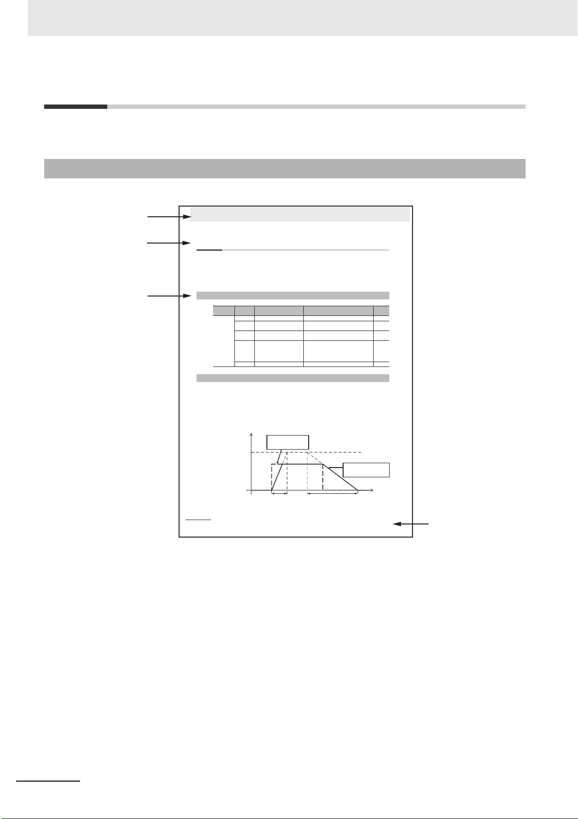
7-9 Soft Start Function
This function sets the acceleration and deceleration against the velocity command input inside the
Servo Drive and uses these values for speed control.
With this function, soft starts are possible when the step rotation velocity commands are input. To
reduce any impacts made by acceleration changes, you can also use the velocity command filter
(first-order lag).
For a step velocity command input, set the time until the velocity command reaches 1,000 r/min in
Acceleration Time.
Similarly, set the time until the velocity command slows from 1,000 r/min down to 0 r/min in Deceleration Time.
Acceleration Time (ms) = Vc/1,000 r/min × Acceleration Time × 0.1 ms
Deceleration Time (ms) = Vc/1,000 r/min × Deceleration Time × 0.1 ms
7-9-1 Objects Requiring Settings
Index
(hex)
Subindex
(hex)
Name Description
Refer-
ence
3021
–
Velocity Command Filter
–
P. 9 -1 9
01 Acceleration Time Sets the acceleration time during accelera-
tion.
P. 9 -1 9
02 Deceleration Time Sets the deceleration time during decelera-
tion.
P. 9 -1 9
03 IIR Filter Enable Selects whether to enable or disable the
IIR filter in the velocity command filter.
0: Disabled
1: Enabled
P. 9 -2 0
04 Filter Cutoff Frequency Sets the cutoff frequency for the IIR filter. P. 9-20
7-9-2 Soft Start Acceleration/Deceleration Time
Time
Velocity command [r/min]
Acceleration Time × 0.1 ms Deceleration Time × 0.1 ms
1,000 [r/min]
Velocity command before
acceleration control
(step type command)
Velocity command after
acceleration control
(trapezoidal type command)
Level 1
heading
Level 2
heading
Level 3
heading
Manual name
Manual Structure
This section explains the page structure and symbol icons.
Page Structure
The following page structure is used in this manual.
Note The above page is only a sample for illustrative purposes. It is not the actual content of this User’s Manual.
2
1S-series with Built-in EtherCAT Communications and Safety Functionality User’s Manual (I621)
Page 5
Precautions for Safe Use
Precautions for Correct Use
Additional Information
Version Information
7 - 31
7 Applied Functions
1S-series AC Servomotors and Servo Drives User’s Manual (with Built-in EtherCAT Communications)
7-9 Soft Start Function
7
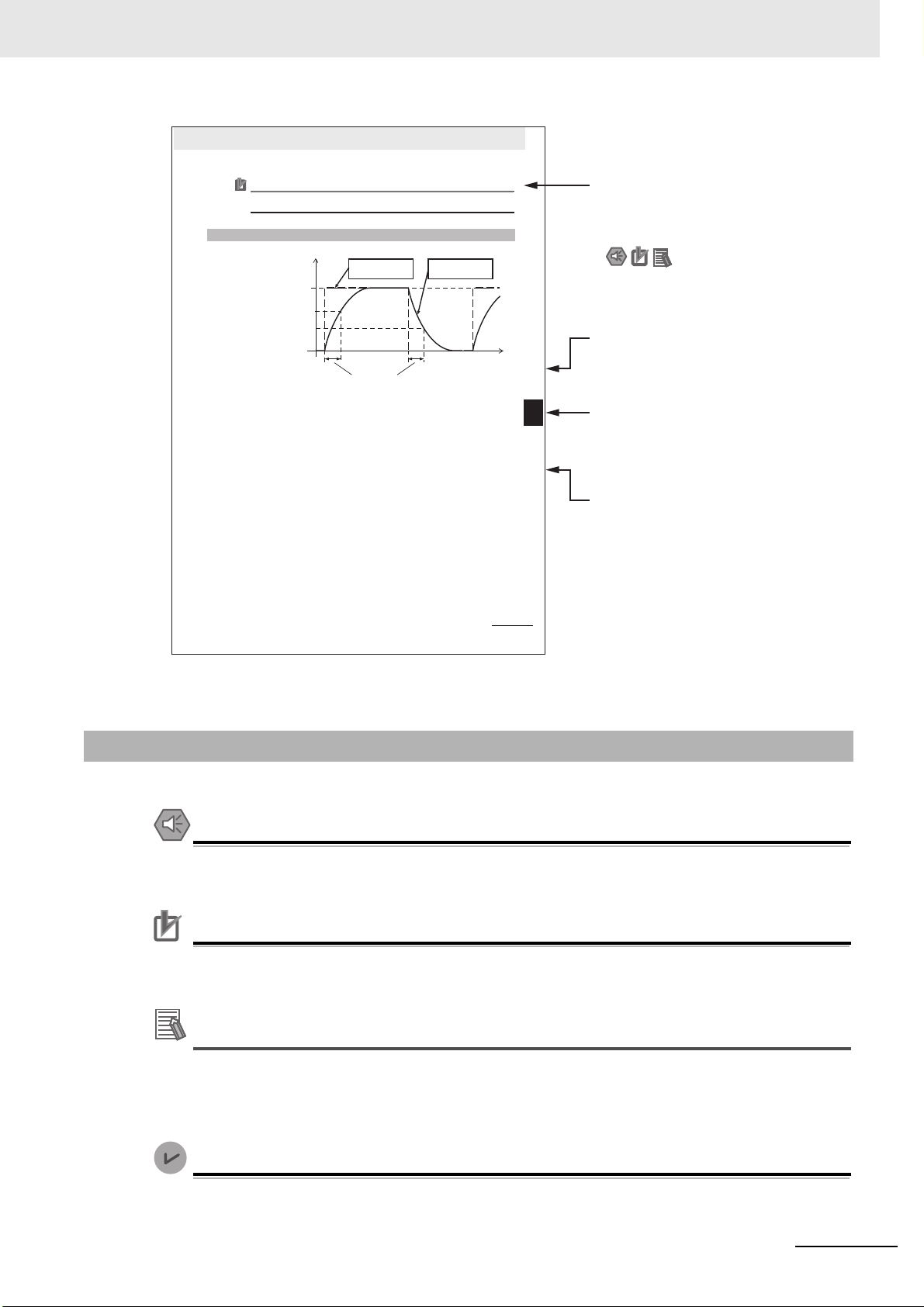
7-9-3 Velocity Command Filter (First-order Lag)
Precautions for Correct Use
Do not set the Acceleration Time and the Deceleration Time when the position loop structure
with a host controller is used.
The velocity command filter (first-order lag) is an IIR filter used for speed commands.
7-9-3 Velocity Command Filter (First-order Lag)
Vc × 0.632
(s)
Vc × 0.368
Time
Velocity command [r/min]
Target velocity
Target velocity
Target velocity
Velocity command
before filter process
Velocity command
after filter process
1/(2π × Filter Cutoff Frequency)
Icons indicate precautions,
additional information, or
reference information.
Special information
Level 2 heading
Gives the current heading.
Page tab
Gives the number of
the main section.
Level 3 heading
Gives the current heading.
Manual Structure
Note This illustration is provided only as a sample. It may not literally appear in this manual.
Special Information
Special information in this manual is classified as follows:
Precautions on what to do and what not to do to ensure safe usage of the product.
Precautions on what to do and what not to do to ensure proper operation and performance.
Additional information to read as required.
This information is provided to increase understanding or make operation easier.
Information on differences in specifications and functionality for Servo Drives with different unit
versions and for different versions of the Sysmac Studio is given.
1S-series with Built-in EtherCAT Communications and Safety Functionality User’s Manual (I621)
3
Page 6

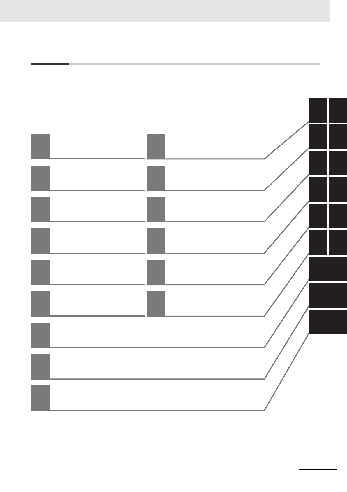
Manual Configuration
Manual Configuration
This User’s Manual consists of the following sections.
Read the necessary section or sections by reference to the following table.
Section Outline
Section 1
Section 2
Section 3 Specifications
Section 4
Section 5
Section 6
Section 7 Applied Functions
Section 8 Safety Function
Section 9
Section 10 Operation
Section 11
Section 12 Troubleshooting
Section 13
Appendices
Features and System Configuration
Models and External Dimensions
Configuration and
Wiring
EtherCAT Communications
Basic Control
Functions
Details on Servo
Parameters
Adjustment Functions
Maintenance and
Inspection
This section explains the features of the Servo Drive and name of each part.
This section explains the models of Servo Drives, Servomotors, Decelerators, and peripheral devices, and provides the external dimensions and
mounting dimensions.
This section provides the general specifications, characteristics, connector
specifications, and I/O circuits of the Servo Drives as well as the general
specifications, characteristics, encoder specifications of the Servomotors
and other peripheral devices.
This section explains the conditions for installing Servo Drives, Servomotors,
and Decelerators, the wiring methods including wiring conforming to EMC
Directives, the regenerative energy calculation methods, as well as the performance of External Regeneration Resistors.
This section explains EtherCAT communications under the assumption that
the Servo Drive is connected to a Machine Automation Controller
NJ/NX-series CPU Unit, NY-series IPC Machine Controller, or Position Control Unit (Model: CJ1W-NC8).
This section explains the outline and settings of basic control functions.
This section provides the outline and settings of the applied functions such
as electronic gear and gain switching.
This section provides the outline of each safety function (STO, SS1, SS2,
SOS, SLS, SLP, SDI, and SBC) and examples of operation and connection.
This section explains the details on each servo parameter, including the set
values, settings, and the display.
This section provides the operational procedure and explains how to operate
in each mode.
This section explains the functions, setting methods, and items to note
regarding adjustments.
This section explains the items to check when problems occur, and troubleshooting by the use of error displays or operation state.
This section explains maintenance and inspection of the Servomotors and
Servo Drives.
The appendices provide explanation for the profile that is used to control the
Servo Drive, lists of objects, and Sysmac error status codes.
4
1S-series with Built-in EtherCAT Communications and Safety Functionality User’s Manual (I621)
Page 7
1
10
2
11
3
4
13
5
6
7
8
9
1
10
2
11
12
3
4
13
5A
6 I
7
8
9
A
I
Features and System
Configuration
Models and External
Dimensions
Operation
Specifications
Adjustment Functions
12
Troubleshooting
Configuration and
Wiring
Maintenance and
Inspection
EtherCAT
Communications
Appendices
Applied Functions
Basic Control
Functions
Index
Safety Function
Details on Servo Parameters
Sections in this Manual
Sections in this Manual
1S-series with Built-in EtherCAT Communications and Safety Functionality User’s Manual (I621)
5
Page 8

CONTENTS
CONTENTS
Introduction ..............................................................................................................1
Manual Structure ......................................................................................................2
Manual Configuration ..............................................................................................4
Sections in this Manual ...........................................................................................5
Terms and Conditions Agreement ........................................................................18
Safety Precautions .................................................................................................20
Items to Check After Unpacking ...........................................................................31
Related Manuals .....................................................................................................39
Terminology ............................................................................................................44
Revision History .....................................................................................................47
Section 1 Features and System Configuration
1-1 Outline .................................................................................................................................. 1-2
1-1-1 Features of 1S-series Servo Drive Advance Type.................................................................... 1-2
1-1-2 EtherCAT .................................................................................................................................. 1-3
1-1-3 Object Dictionary ...................................................................................................................... 1-4
1-2 System Configuration .........................................................................................................1-5
1-3 Names and Functions ......................................................................................................... 1-6
1-3-1 Servo Drive Part Names ........................................................................................................... 1-6
1-3-2 Servo Drive Functions ............................................................................................................1-10
1-3-3 Servomotor Part Names ......................................................................................................... 1-13
1-3-4 Servomotor Functions............................................................................................................. 1-15
1-3-5 Shield Clamp Part Names ...................................................................................................... 1-16
1-4 System Block Diagram...................................................................................................... 1-17
1-5 Applicable Standards........................................................................................................ 1-21
1-5-1 EU Directives .......................................................................................................................... 1-21
1-5-2 UL and cUL Standards............................................................................................................1-22
1-5-3 Korean Radio Regulations (KC) .............................................................................................1-23
1-5-4 SEMI F47................................................................................................................................ 1-23
1-5-5 Australian EMC Labeling Requirements (RCM) ..................................................................... 1-23
1-5-6 EAC Requirements ................................................................................................................. 1-23
1-6 Unit Versions...................................................................................................................... 1-24
1-6-1 Confirmation Method ..............................................................................................................1-24
1-6-2 Unit Versions and Sysmac Studio Versions ............................................................................1-24
1-7 Procedures to Start Operation ......................................................................................... 1-25
1-7-1 Overall Procedure...................................................................................................................1-25
1-7-2 Procedure Details ................................................................................................................... 1-27
Section 2 Models and External Dimensions
2-1 Servo System Configuration .............................................................................................. 2-2
6
1S-series with Built-in EtherCAT Communications and Safety Functionality User’s Manual (I621)
Page 9

CONTENTS
2-2 How to Read Model Numbers............................................................................................. 2-4
2-2-1 Servo Drive............................................................................................................................... 2-4
2-2-2 Servomotor............................................................................................................................... 2-5
2-2-3 Integrated Cable....................................................................................................................... 2-6
2-2-4 Decelerator............................................................................................................................... 2-7
2-3 Model Tables........................................................................................................................ 2-9
2-3-1 Servo Drive Model Table .......................................................................................................... 2-9
2-3-2 Servomotor Model Tables....................................................................................................... 2-10
2-3-3 Servo Drive and Servomotor Combination Tables.................................................................. 2-12
2-3-4 Decelerator Model Tables....................................................................................................... 2-13
2-3-5 Servomotor and Decelerator Combination Tables.................................................................. 2-15
2-3-6 Table of Integrated Cables, Connectors, and Shield Clamps ................................................. 2-16
2-3-7 External Regeneration Resistor and External Regeneration Resistance Unit
Model Tables .......................................................................................................................... 2-19
2-3-8 Reactor Model Table............................................................................................................... 2-20
2-4 External and Mounting Dimensions ................................................................................ 2-21
2-4-1 Servo Drive Dimensions......................................................................................................... 2-21
2-4-2 Servomotor Dimensions ......................................................................................................... 2-23
2-4-3 Cable Outlet Direction of Integrated Connector ..................................................................... 2-43
2-4-4 Cable Wiring Dimension for a Case of Servomotor Installing ................................................ 2-44
2-4-5 Decelerator Dimensions ......................................................................................................... 2-46
2-4-6 Dimensions of External Regeneration Resistors and
External Regeneration Resistance Units................................................................................ 2-55
2-4-7 Reactor Dimensions ............................................................................................................... 2-56
Section 3 Specifications
3-1 Servo Drive Specifications ................................................................................................. 3-3
3-1-1 General Specifications ............................................................................................................. 3-3
3-1-2 Characteristics.......................................................................................................................... 3-4
3-1-3 EtherCAT Communications Specifications ............................................................................... 3-8
3-1-4 Main Circuit and Motor Connections ........................................................................................ 3-9
3-1-5 Control I/O Connector (CN1) Specifications........................................................................... 3-14
3-1-6 Control Input Circuits.............................................................................................................. 3-16
3-1-7 Control Input Details............................................................................................................... 3-17
3-1-8 Control Output Circuits ........................................................................................................... 3-18
3-1-9 Control Output Details ............................................................................................................ 3-19
3-1-10 Encoder Pulse Output Specifications ..................................................................................... 3-19
3-1-11 Safety Signal Connector (CN14) Specifications..................................................................... 3-20
3-1-12 Safe Brake Control Connector (CN15) Specifications............................................................ 3-24
3-1-13 Brake Interlock Connector (CN12) Specifications .................................................................. 3-25
3-1-14 Encoder Connector (CN2) Specifications............................................................................... 3-26
3-1-15 EtherCAT Communications Connector (RJ45) Specifications................................................ 3-26
3-1-16 USB Connector (CN7) Specifications..................................................................................... 3-27
3-1-17 Power ON Sequence.............................................................................................................. 3-27
3-1-18 Overload Characteristics (Electronic Thermal Function) ........................................................ 3-28
3-2 Servomotor Specifications ............................................................................................... 3-31
3-2-1 General Specifications ........................................................................................................... 3-31
3-2-2 Encoder Specifications........................................................................................................... 3-32
3-2-3 Characteristics........................................................................................................................ 3-33
3-3 Decelerator Specifications ............................................................................................... 3-44
3-4 Cable and Connector Specifications ............................................................................... 3-47
3-4-1 Integrated Cable Specifications.............................................................................................. 3-47
3-4-2 Combination of Integrated Cable and Extension Cable ......................................................... 3-67
3-4-3 Resistance to Bending of Integrated Cable............................................................................ 3-68
3-4-4 EtherCAT Communications Cable Specifications................................................................... 3-69
3-5 Specifications of External Regeneration Resistors and
External Regeneration Resistance Units ........................................................................ 3-72
3-5-1 General Specifications ........................................................................................................... 3-72
3-5-2 Characteristics........................................................................................................................ 3-72
1S-series with Built-in EtherCAT Communications and Safety Functionality User’s Manual (I621)
7
Page 10

CONTENTS
3-5-3 External Regeneration Resistance Unit Specifications...........................................................3-74
3-6 Reactor Specifications...................................................................................................... 3-75
3-6-1 General Specifications............................................................................................................ 3-75
3-6-2 Characteristics ........................................................................................................................ 3-75
3-6-3 Terminal Block Specifications ................................................................................................. 3-76
3-7 Noise Filter Specifications................................................................................................ 3-77
Section 4 Configuration and Wiring
4-1 Installation Conditions........................................................................................................ 4-2
4-1-1 Servo Drive Installation Conditions ........................................................................................... 4-2
4-1-2 Servomotor Installation Conditions ........................................................................................... 4-5
4-1-3 Decelerator Installation Conditions ........................................................................................... 4-9
4-1-4 External Regeneration Resistor and External Regeneration Resistance Unit Conditions ......4-13
4-2 Wiring ................................................................................................................................. 4-14
4-2-1 Peripheral Equipment Connection Examples .........................................................................4-15
4-2-2 Procedure for Wiring Connector-type Terminal Blocks and for Mounting a Shield Clamp...... 4-25
4-2-3 Procedure for Attaching an Integrated Connector ..................................................................4-28
4-2-4 Procedure for Change of Cable Outlet Direction for Integrated Cable ................................... 4-30
4-3 Wiring Conforming to EMC Directives ............................................................................ 4-32
4-3-1 Peripheral Equipment Connection Examples .........................................................................4-33
4-3-2 Selecting Connection Component .......................................................................................... 4-39
4-4 Regenerative Energy Absorption..................................................................................... 4-44
4-4-1 Calculating the Regenerative Energy .....................................................................................4-44
4-4-2 Servo Drive Regeneration Absorption Capacity ..................................................................... 4-47
4-4-3 Regenerative Energy Absorption by an External Regeneration Resistance Device............... 4-48
4-4-4 Connecting an External Regeneration Resistor......................................................................4-49
4-5 Adjustment for Large Load Inertia................................................................................... 4-50
4-6 Machine Accuracy for Servomotor .................................................................................. 4-51
Section 5 EtherCAT Communications
5-1 Display Area and Settings .................................................................................................. 5-2
5-1-1 Node Address Setting ...............................................................................................................5-2
5-1-2 Status Indicators.......................................................................................................................5-3
5-2 Structure of the CAN Application Protocol over EtherCAT ............................................. 5-5
5-3 EtherCAT State Machine ..................................................................................................... 5-6
5-4 Process Data Objects (PDOs) ............................................................................................ 5-7
5-4-1 PDO Mapping Settings ............................................................................................................. 5-7
5-4-2 Sync Manager PDO Assignment Settings ................................................................................ 5-8
5-4-3 Fixed PDO Mapping .................................................................................................................5-8
5-4-4 Variable PDO Mapping ........................................................................................................... 5-11
5-4-5 Safety PDO Mapping .............................................................................................................. 5-12
5-4-6 Sync Manager PDO Mapping Assignment Settings ...............................................................5-14
5-5 Service Data Objects (SDOs)............................................................................................ 5-15
5-6 Synchronization Mode and Communications Cycle ...................................................... 5-16
5-6-1 Distributed Clock (DC) Mode ..................................................................................................5-16
5-6-2 Free-Run Mode....................................................................................................................... 5-16
5-7 Emergency Messages ....................................................................................................... 5-17
5-8 Sysmac Device Features .................................................................................................. 5-18
5-9 Cable Redundancy Function ............................................................................................ 5-22
5-9-1 Objects Requiring Settings .....................................................................................................5-22
5-9-2 Description of Operation ......................................................................................................... 5-22
8
1S-series with Built-in EtherCAT Communications and Safety Functionality User’s Manual (I621)
Page 11

5-9-3 Procedure of Checking Operation .......................................................................................... 5-23
5-9-4 Slave Communications Statuses When Cable Redundancy Function Is Used...................... 5-25
5-9-5 Relation between the Network Configuration Information and the Actual Configuration........ 5-26
Section 6 Basic Control Functions
6-1 Outline of Control Functions.............................................................................................. 6-2
6-1-1 Basic Control and Control Methods..........................................................................................6-2
6-1-2 Control Method......................................................................................................................... 6-3
6-2 Control Blocks ..................................................................................................................... 6-5
6-2-1 Block Diagram for Position Control .......................................................................................... 6-5
6-2-2 Block Diagram for Velocity Control........................................................................................... 6-7
6-2-3 Block Diagram for Torque Control ............................................................................................ 6-9
6-3 Cyclic Synchronous Position Mode ................................................................................ 6-10
6-4 Cyclic Synchronous Velocity Mode................................................................................. 6-12
6-5 Cyclic Synchronous Torque Mode................................................................................... 6-14
6-6 Profile Position Mode........................................................................................................6-16
CONTENTS
6-7 Profile Velocity Mode ........................................................................................................6-21
6-8 Homing Mode..................................................................................................................... 6-24
6-9 Connecting with OMRON Controllers.............................................................................. 6-25
Section 7 Applied Functions
7-1 General-purpose Input Signals .......................................................................................... 7-3
7-1-1 Objects Requiring Settings....................................................................................................... 7-4
7-1-2 Default Setting.......................................................................................................................... 7-6
7-1-3 Function Input Details............................................................................................................... 7-7
7-2 General-purpose Output Signals ....................................................................................... 7-8
7-2-1 Objects Requiring Settings....................................................................................................... 7-8
7-2-2 Default Setting........................................................................................................................ 7-10
7-2-3 Function Output Details...........................................................................................................7-11
7-3 Drive Prohibition Functions ............................................................................................. 7-15
7-3-1 Objects Requiring Settings..................................................................................................... 7-15
7-3-2 Description of Operation......................................................................................................... 7-16
7-4 Software Position Limit Functions .................................................................................. 7-17
7-4-1 Operating Conditions.............................................................................................................. 7-17
7-4-2 Objects Requiring Settings..................................................................................................... 7-17
7-4-3 Description of Operation......................................................................................................... 7-18
7-5 Backlash Compensation................................................................................................... 7-20
7-5-1 Operating Conditions.............................................................................................................. 7-20
7-5-2 Objects Requiring Settings..................................................................................................... 7-20
7-5-3 Description of Operation......................................................................................................... 7-21
7-6 Brake Interlock................................................................................................................... 7-22
7-6-1 Objects Requiring Settings..................................................................................................... 7-22
7-6-2 Description of Operation......................................................................................................... 7-24
7-6-3 Operation Timing.................................................................................................................... 7-25
7-7 Electronic Gear Function.................................................................................................. 7-29
7-7-1 Objects Requiring Settings..................................................................................................... 7-29
7-7-2 Operation Example................................................................................................................. 7-29
7-8 Torque Limit Switching ..................................................................................................... 7-30
7-8-1 Operating Conditions.............................................................................................................. 7-30
7-8-2 Objects Requiring Settings..................................................................................................... 7-30
7-8-3 Torque Limit Switching Method ..............................................................................................7-31
1S-series with Built-in EtherCAT Communications and Safety Functionality User’s Manual (I621)
9
Page 12

CONTENTS
7-9 Soft Start ............................................................................................................................ 7-32
7-10 Gain Switching Function .................................................................................................. 7-34
7-11 Touch Probe Function (Latch Function).......................................................................... 7-38
7-12 Encoder Dividing Pulse Output Function ....................................................................... 7-42
7-13 Dynamic Brake................................................................................................................... 7-45
7-14 Command Compensation Function for Communications Error ................................... 7-49
7-9-1 Objects Requiring Settings .....................................................................................................7-32
7-9-2 Soft Start Acceleration/Deceleration Time .............................................................................. 7-32
7-9-3 Velocity Command First-order Lag Filter ................................................................................ 7-33
7-10-1 Objects Requiring Settings ..................................................................................................... 7-34
7-10-2 Mode Selection .......................................................................................................................7-36
7-10-3 Gain Switching in Position Control..........................................................................................7-37
7-11-1 Related Objects ......................................................................................................................7-38
7-11-2 Trigger Signal Settings............................................................................................................7-40
7-11-3 Operation Sequence...............................................................................................................7-41
7-12-1 Objects Requiring Settings ..................................................................................................... 7-43
7-12-2 Dividing Ratio..........................................................................................................................7-43
7-12-3 Output Reverse Selection ....................................................................................................... 7-44
7-12-4 Z-phase Output ....................................................................................................................... 7-44
7-13-1 Operating Conditions .............................................................................................................. 7-45
7-13-2 Objects Requiring Settings ..................................................................................................... 7-45
7-13-3 Description of Operation ......................................................................................................... 7-46
7-14-1 Operating Conditions .............................................................................................................. 7-49
7-14-2 Operation Example ................................................................................................................. 7-49
Section 8 Safety Function
8-1 Outline of Safety Functions................................................................................................ 8-3
8-1-1 Description of Safety Functions ................................................................................................ 8-3
8-1-2 Configuration for Safety System ............................................................................................... 8-4
8-1-3 Network Connection and Settings ............................................................................................8-7
8-1-4 Operating Procedure for Safety Function ................................................................................. 8-8
8-1-5 Safety Reaction Time for Safety Distance .............................................................................. 8-11
8-1-6 Data Necessary for Designing Programs of Each Controller..................................................8-12
8-1-7 PFH.........................................................................................................................................8-15
8-1-8 Position/Velocity Data Monitored by Safety Functions ........................................................... 8-16
8-1-9 Precaution on Use .................................................................................................................. 8-19
8-1-10 Procedure for Reset of Safety Error .......................................................................................8-20
8-1-11 Safety Program.......................................................................................................................8-21
8-2 Safe Torque OFF (STO) Function ..................................................................................... 8-22
8-2-1 STO Function via Safety Input Signals ...................................................................................8-23
8-2-2 STO Function via EtherCAT Communications ........................................................................ 8-32
8-2-3 STO with SBC Functions via EtherCAT Communications ......................................................8-36
8-3 Safe Stop 1 (SS1) Function............................................................................................... 8-39
8-3-1 Objects Requiring Settings .....................................................................................................8-41
8-3-2 Operation Procedure ..............................................................................................................8-43
8-3-3 Operation Timing ....................................................................................................................8-44
8-3-4 Example of Safety Program.................................................................................................... 8-47
8-3-5 Concurrent Use of SS1 Function and SBC Function..............................................................8-48
8-4 Safe Stop 2 (SS2) Function............................................................................................... 8-54
8-4-1 Objects Requiring Settings .....................................................................................................8-55
8-4-2 Operation Procedure ..............................................................................................................8-57
8-4-3 Operation Timing ....................................................................................................................8-58
8-4-4 Example of Safety Program.................................................................................................... 8-61
8-5 Safe Operating Stop (SOS) Function............................................................................... 8-62
8-5-1 Objects Requiring Settings .....................................................................................................8-62
8-5-2 Operation Procedure ..............................................................................................................8-63
8-5-3 Operation Timing ....................................................................................................................8-64
10
1S-series with Built-in EtherCAT Communications and Safety Functionality User’s Manual (I621)
Page 13

CONTENTS
8-5-4 Example of Safety Program ................................................................................................... 8-67
8-6 Safely-limited Speed (SLS) Function............................................................................... 8-68
8-6-1 Objects Requiring Settings..................................................................................................... 8-70
8-6-2 Operation Procedure .............................................................................................................. 8-72
8-6-3 Operation Timing.................................................................................................................... 8-73
8-6-4 Example of Safety Program .................................................................................................. 8-78
8-7 Safely-limited Position (SLP) Function ........................................................................... 8-79
8-7-1 Configuration Example for SLP System ................................................................................. 8-79
8-7-2 Objects Requiring Settings..................................................................................................... 8-81
8-7-3 Operation Procedure ............................................................................................................. 8-84
8-7-4 Operation Timing.................................................................................................................... 8-85
8-7-5 Example of Safety Program .................................................................................................. 8-88
8-7-6 Setting of Safety Origin Position............................................................................................. 8-89
8-8 Safe Direction (SDI) Function......................................................................................... 8-102
8-8-1 Objects Requiring Settings.................................................................................................. 8-102
8-8-2 Operation Procedure ........................................................................................................... 8-103
8-8-3 Operation Timing.................................................................................................................. 8-104
8-8-4 Example of Safety Program .................................................................................................8-110
8-9 Safe Brake Control (SBC) Function ............................................................................... 8-112
8-9-1 Configuration Method for SBC ..............................................................................................8-113
8-9-2 Objects Requiring Settings....................................................................................................8-115
8-9-3 Operation Procedure .............................................................................................................8-116
8-9-4 Connection Method ...............................................................................................................8-117
8-9-5 Connection Examples ...........................................................................................................8-119
8-9-6 Operation Timing.................................................................................................................. 8-120
8-9-7 SBC Power Monitor.............................................................................................................. 8-120
8-9-8 Safety Relay Stuck Error Detection...................................................................................... 8-122
8-10 Safety Position/Velocity Validation Monitoring Function ............................................ 8-124
8-10-1 Details about Validation Monitoring ...................................................................................... 8-124
8-10-2 Objects Requiring Settings................................................................................................... 8-125
8-10-3 Operation Procedure ............................................................................................................ 8-125
8-10-4 Operation Timing.................................................................................................................. 8-126
Section 9 Details on Servo Parameters
9-1 Object Description Format ................................................................................................. 9-5
9-2 Common Control Objects ................................................................................................... 9-7
9-2-1 3000 hex: Basic Functions ....................................................................................................... 9-7
9-2-2 3001 hex: Machine ................................................................................................................. 9-13
9-2-3 3002 hex: Optimized Parameters........................................................................................... 9-14
9-2-4 3010 hex: Position Command ................................................................................................ 9-16
9-2-5 3011 hex: Position Command Filter........................................................................................ 9-18
9-2-6 3012 hex: Damping Control.................................................................................................... 9-19
9-2-7 3013 hex: Damping Filter 1 .................................................................................................... 9-20
9-2-8 3014 hex: Damping Filter 2 .................................................................................................... 9-21
9-2-9 3020 hex: Velocity Command.................................................................................................9-23
9-2-10 3021 hex: Velocity Command Filter........................................................................................ 9-24
9-2-11 3030 hex: Torque Command ..................................................................................................9-25
9-2-12 3031 hex: Velocity Limit in Torque Control ............................................................................. 9-25
9-2-13 3040 hex: Profile Command ...................................................................................................
9-2-14 3041 hex: Command Dividing Function ................................................................................. 9-27
9-3 Control Method Objects.................................................................................................... 9-29
9-3-1 3112 hex: ODF Velocity Feed-forward.................................................................................... 9-29
9-3-2 3113 hex: ODF Torque Feed-forward ..................................................................................... 9-30
9-3-3 3120 hex: TDF Position Control .............................................................................................9-31
9-3-4 3121 hex: TDF Velocity Control.............................................................................................. 9-32
9-4 Control Loop Objects........................................................................................................ 9-34
9-4-1 3210 hex: Internal Position Command ................................................................................... 9-34
9-4-2 3211 hex: Position Detection.................................................................................................. 9-35
9-26
1S-series with Built-in EtherCAT Communications and Safety Functionality User’s Manual (I621)
11
Page 14

CONTENTS
9-5 Torque Output Setting Objects ........................................................................................ 9-44
9-6 Homing Objects ................................................................................................................. 9-57
9-7 Applied Function Objects ................................................................................................. 9-61
9-8 Error- and Warning-related Objects................................................................................. 9-81
9-9 Monitoring-related Objects............................................................................................... 9-87
9-10 Display-related Objects.....................................................................................................9-98
9-11 Power Device-related Objects .......................................................................................... 9-99
9-12 External Device-related Objects..................................................................................... 9-102
9-13 Encoder-related Objects ................................................................................................. 9-104
9-4-3 3212 hex: Gain Switching in Position Control.........................................................................9-35
9-4-4 3213 hex: 1st Position Control Gain ....................................................................................... 9-36
9-4-5 3214 hex: 2nd Position Control Gain ...................................................................................... 9-37
9-4-6 3220 hex: Internal Velocity Command....................................................................................9-37
9-4-7 3221 hex: Velocity Detection .................................................................................................. 9-38
9-4-8 3222 hex: Gain Switching in Velocity Control .........................................................................9-39
9-4-9 3223 hex: 1st Velocity Control Gain........................................................................................9-39
9-4-10 3224 hex: 2nd Velocity Control Gain ......................................................................................9-40
9-4-11 3230 hex: Internal Torque Command......................................................................................9-41
9-4-12 3231 hex: Torque Detection.................................................................................................... 9-41
9-4-13 3232 hex: Filter Switching in Torque Control ..........................................................................9-41
9-4-14 3233 hex: 1st Torque Command Filter.................................................................................... 9-42
9-4-15 3234 hex: 2nd Torque Command Filter...................................................................................9-43
9-5-1 3310 hex: Torque Compensation............................................................................................9-44
9-5-2 3320 hex: Adaptive Notch Filter..............................................................................................9-46
9-5-3 3321 hex: 1st Notch Filter.......................................................................................................9-47
9-5-4 3322 hex: 2nd Notch Filter...................................................................................................... 9-49
9-5-5 3323 hex: 3rd Notch Filter ......................................................................................................9-51
9-5-6 3324 hex: 4th Notch Filter.......................................................................................................9-53
9-5-7 3330 hex: Torque Limit............................................................................................................9-55
9-7-1 3B10 hex: Drive Prohibition .................................................................................................... 9-61
9-7-2 3B11 hex: Software Position Limit ..........................................................................................9-62
9-7-3 3B20 hex: Stop Selection .......................................................................................................9-64
9-7-4 3B21 hex: Deceleration Stop ..................................................................................................9-66
9-7-5 3B30 hex: Touch Probe 1........................................................................................................9-67
9-7-6 3B31 hex: Touch Probe 2........................................................................................................9-70
9-7-7 3B40 hex: Zone Notification 1.................................................................................................9-71
9-7-8 3B41 hex: Zone Notification 2.................................................................................................9-72
9-7-9 3B50 hex: Position Detection Function ................................................................................... 9-73
9-7-10 3B51 hex: Positioning Completion Notification ....................................................................... 9-73
9-7-11 3B52 hex: Positioning Completion Notification 2 .................................................................... 9-74
9-7-12 3B60 hex: Speed Detection Function .....................................................................................9-75
9-7-13 3B70 hex: Vibration Detection ................................................................................................ 9-76
9-7-14 3B71 hex: Runaway Detection ...............................................................................................9-77
9-7-15 3B80 hex: Load Characteristic Estimation.............................................................................. 9-78
9-8-1 4000 hex: Error Full Code....................................................................................................... 9-81
9-8-2 4020 hex: Warning Customization.......................................................................................... 9-82
9-8-3 4021 hex: Warning Output 1 Setting....................................................................................... 9-84
9-8-4 4022 hex: Warning Output 2 Setting....................................................................................... 9-85
9-8-5 4030 hex: Information Customization ..................................................................................... 9-86
9-9-1 4110 hex: Monitor Data via PDO ............................................................................................ 9-87
9-9-2 4120 hex: EtherCAT Communications Error Count ................................................................9-88
9-9-3 4130 hex: Safety Status Monitor............................................................................................. 9-88
9-9-4 4131 hex: Safety Command Monitor 1 ................................................................................... 9-92
9-9-5 4132 hex: Safety Command Monitor 2 ................................................................................... 9-93
9-9-6 4140 hex: Lifetime Information ............................................................................................... 9-94
9-9-7 4150 hex: Overload ................................................................................................................9-96
9-11-1 4310 hex: Regeneration .........................................................................................................9-99
9-11-2 4320 hex: Main Circuit Power Supply...................................................................................9-100
12
9-14 I/O-related Objects........................................................................................................... 9-107
1S-series with Built-in EtherCAT Communications and Safety Functionality User’s Manual (I621)
Page 15

CONTENTS
9-14-1 4600 hex: I/O Monitor........................................................................................................... 9-107
9-14-2 4601 hex: Function Input ...................................................................................................... 9-108
9-14-3 4602 hex: Function Output ....................................................................................................9-110
9-14-4 4604 hex: Control Input Change Count .................................................................................9-111
9-14-5 4605 hex: Control Output Change Count ..............................................................................9-112
9-14-6 4610 hex: Brake Interlock Output..........................................................................................9-113
9-14-7 4620 hex: Encoder Dividing Pulse Output.............................................................................9-114
9-15 General-purpose Input Setting Objects......................................................................... 9-116
9-15-1 Setting ...................................................................................................................................9-116
9-15-2 4630 hex: Positive Drive Prohibition Input.............................................................................9-11 7
9-15-3 4631 hex: Negative Drive Prohibition Input ...........................................................................9-117
9-15-4 4632 hex: External Latch Input 1...........................................................................................9-117
9-15-5 4633 hex: External Latch Input 2...........................................................................................9-118
9-15-6 4634 hex: Home Proximity Input ...........................................................................................9-118
9-15-7 4635 hex: Positive Torque Limit Input....................................................................................9-118
9-15-8 4636 hex: Negative Torque Limit Input ..................................................................................9-119
9-15-9 4637 hex: Error Stop Input ....................................................................................................9-119
9-15-10 4638 hex: Monitor Input 1......................................................................................................9-119
9-15-11 4639 hex: Monitor Input 2..................................................................................................... 9-120
9-15-12 463A hex: Monitor Input 3 .................................................................................................... 9-120
9-15-13 463B hex: Monitor Input 4 .................................................................................................... 9-120
9-15-14
9-15-15 463D hex: Monitor Input 6 .................................................................................................... 9-121
9-15-16 463E hex: Monitor Input 7 .................................................................................................... 9-121
9-15-17 463F hex: Monitor Input 8 .................................................................................................... 9-122
9-16 General-purpose Output Setting Objects...................................................................... 9-123
9-16-1 Setting .................................................................................................................................. 9-123
9-16-2 4650 hex: Error Output......................................................................................................... 9-124
9-16-3 4651 hex: Servo Ready Output ............................................................................................ 9-124
9-16-4 4652 hex: Positioning Completion Output 1 ......................................................................... 9-124
9-16-5 4653 hex: Positioning Completion Output 2 ......................................................................... 9-125
9-16-6 4654 hex: Velocity Attainment Detection Output .................................................................. 9-125
9-16-7 4655 hex: Torque Limit Output ............................................................................................. 9-125
9-16-8 4656 hex: Zero Speed Detection Output .............................................................................. 9-126
9-16-9 4657 hex: Velocity Conformity Output .................................................................................. 9-126
9-16-10 4658 hex: Warning Output 1................................................................................................. 9-126
9-16-11 4659 hex: Warning Output 2................................................................................................. 9-127
9-16-12 465A hex: Velocity Limiting Output....................................................................................... 9-127
9-16-13 465B hex: Error Clear Attribute Output................................................................................. 9-127
9-16-14 465C hex: Remote Output 1................................................................................................. 9-128
9-16-15
9-16-16 465E hex: Remote Output 3................................................................................................. 9-128
9-16-17 465F hex: Zone Notification Output 1................................................................................... 9-129
9-16-18 4660 hex: Zone Notification Output 2................................................................................... 9-129
9-16-19 4661 hex: Position Command Status Output ....................................................................... 9-129
9-16-20 4662 hex: Distribution Completed Output ............................................................................ 9-130
9-16-21 4663 hex: External Brake Interlock Output........................................................................... 9-130
9-17 Safety Related Object...................................................................................................... 9-132
9-17-1 4F00 hex: Safety Origin Position Setting.............................................................................. 9-132
9-17-2 4F01 hex: Safety Position/Velocity Validation Monitoring Function ...................................... 9-134
9-17-3 4F02 hex: Discrepancy Distance Measurement................................................................... 9-135
9-17-4 4F03 hex: Safety Motor Rotation Direction Selection........................................................... 9-136
9-17-5 4F08 hex: Safety Relay Activate .......................................................................................... 9-137
9-17-6 4F09 hex: Safety Relay OFF Delay Time 1 .......................................................................... 9-137
9-17-7 4F0A hex: Safety Relay OFF Delay Time 2.......................................................................... 9-137
9-17-8 4F16 hex: Error Detection Activate In SLS Deactivate......................................................... 9-138
9-17-9 4F18 hex: Safety Present Pulse Position ............................................................................. 9-138
9-17-10 4F19 hex: Safety Present Position ....................................................................................... 9-139
9-17-11 4F1A hex: Safety Present Motor Velocity ............................................................................. 9-139
9-17-12 4F20 hex: Safety Function Disable Setting .......................................................................... 9-140
463C hex: Monitor Input 5 .................................................................................................... 9-121
465D hex: Remote Output 2................................................................................................. 9-128
1S-series with Built-in EtherCAT Communications and Safety Functionality User’s Manual (I621)
13
Page 16

CONTENTS
Section 10 Operation
10-1 Operational Procedure...................................................................................................... 10-2
10-2 Preparing for Operation .................................................................................................... 10-3
10-2-1 Items to Check Before Turning ON the Power Supply............................................................ 10-3
10-2-2 Turning ON the Power Supply ................................................................................................ 10-4
10-2-3 Checking the Displays ............................................................................................................ 10-5
10-2-4 Absolute Encoder Setup ......................................................................................................... 10-7
10-2-5 Setting Up an Absolute Encoder from the Sysmac Studio......................................................10-7
10-3 Test Run ............................................................................................................................. 10-8
10-3-1 Preparations for Test Run ....................................................................................................... 10-8
10-3-2 Test Run via USB Communications from the Sysmac Studio.................................................10-9
10-4 Confirmation of Safety Functions.................................................................................. 10-10
10-4-1 Preparation Before Confirmation of Safety Function ............................................................ 10-10
10-4-2 Confirmation of Safety Function ........................................................................................... 10-10
Section 11 Adjustment Functions
11-1 Outline of Adjustment Functions..................................................................................... 11-3
11-1-1 Adjustment Methods ............................................................................................................... 11-3
11-1-2 Adjustment Procedure ............................................................................................................ 11-4
11-2 Easy Tuning ....................................................................................................................... 11-6
11-2-1 Objects That Are Set............................................................................................................... 11-6
11-2-2 Executing Easy Tuning ........................................................................................................... 11-8
11-3 Advanced Tuning............................................................................................................... 11-9
11-3-1 Objects That Are Set............................................................................................................... 11-9
11-3-2 Executing Advanced Tuning ................................................................................................. 11-10
11-4 Manual Tuning ..................................................................................................................11-11
11-4-1 Objects That Are Set..............................................................................................................11-11
11-4-2 Executing Manual Tuning ......................................................................................................11-11
11-5 Data Trace ........................................................................................................................ 11-12
11-6 FFT .................................................................................................................................... 11-13
11-7 Damping Control ............................................................................................................. 11-14
11-7-1 Objects Requiring Settings ................................................................................................... 11-14
11-7-2 Operating Procedure ............................................................................................................ 11-16
11-7-3 Setting Frequency with Sysmac Studio ................................................................................ 11-17
11-8 Load Characteristic Estimation...................................................................................... 11-18
11-8-1 Objects Requiring Settings ................................................................................................... 11-19
11-8-2 Setting Load Characteristic Estimation Function .................................................................. 11-20
11-9 Adaptive Notch Filter ...................................................................................................... 11-21
11-9-1 Objects Requiring Settings ................................................................................................... 11-21
11-9-2 Operating Procedure ............................................................................................................ 11-22
11-10 Notch Filters..................................................................................................................... 11-23
11-10-1 Objects Requiring Settings ................................................................................................... 11-24
11-10-2 Notch Filter Width and Depth................................................................................................ 11-25
11-11 Friction Torque Compensation Function ...................................................................... 11-26
11-11-1 Operating Conditions ............................................................................................................ 11-26
11-11-2 Objects Requiring Settings ................................................................................................... 11-26
11-11-3 Operation Example ............................................................................................................... 11-27
11-12 Feed-forward Function.................................................................................................... 11-29
11-12-1 Feed-forward Control in TDF Control.................................................................................... 11-29
11-12-2 Feed-forward Control in ODF Control................................................................................... 11-31
14
1S-series with Built-in EtherCAT Communications and Safety Functionality User’s Manual (I621)
Page 17

Section 12 Troubleshooting
12-1 Actions for Problems ........................................................................................................12-2
12-1-1 Preliminary Checks When a Problem Occurs ........................................................................ 12-2
12-1-2 Precautions When a Problem Occurs .................................................................................... 12-3
12-1-3 Replacing the Servomotor or Servo Drive.............................................................................. 12-4
12-2 Warnings ............................................................................................................................ 12-6
12-2-1 Related Objects...................................................................................................................... 12-6
12-2-2 Warning List............................................................................................................................ 12-8
12-3 Errors................................................................................................................................ 12-10
12-3-1 Error List............................................................................................................................... 12-10
12-3-2 Deceleration Stop Operation at Errors ................................................................................. 12-13
12-4 Information....................................................................................................................... 12-14
12-4-1 Related Objects.................................................................................................................... 12-14
12-4-2 Information List..................................................................................................................... 12-14
12-5 Troubleshooting .............................................................................................................. 12-15
12-5-1 Troubleshooting Using Error Displays.................................................................................. 12-16
12-5-2 Troubleshooting Using AL Status Codes .............................................................................. 12-41
12-5-3 Troubleshooting Using the Operation State ......................................................................... 12-45
CONTENTS
Section 13 Maintenance and Inspection
13-1 Periodic Maintenance........................................................................................................13-2
13-2 Servo Drive Lifetime.......................................................................................................... 13-3
13-3 Servomotor Lifetime.......................................................................................................... 13-4
13-4 Method for Ring Disconnection Maintenance and Inspection ...................................... 13-5
Appendices
A-1 CiA 402 Drive Profile ...........................................................................................................A-2
A-1-1 Controlling the State Machine of the Servo Drive .................................................................... A-2
A-1-2 Modes of Operation.................................................................................................................. A-4
A-1-3 Modes of Operation and Applied/Adjustment Functions ..........................................................A-5
A-1-4 Changing the Mode of Operation .............................................................................................A-5
A-1-5 Homing Mode Specifications .................................................................................................... A-7
A-2 CoE Objects .......................................................................................................................A-12
A-2-1 Object Dictionary Area............................................................................................................A-12
A-2-2 Data Type...............................................................................................................................A-12
A-2-3 Object Description Format...................................................................................................... A-13
A-2-4 Communication Objects .........................................................................................................A-14
A-2-5 PDO Mapping Objects............................................................................................................ A-19
A-2-6 Sync Manager Communication Objects ................................................................................. A-34
A-2-7 Manufacturer Specific Objects ............................................................................................... A-38
A-2-8 Servo Drive Profile Object...................................................................................................... A-41
A-2-9 Safety Function Objects .........................................................................................................A-61
A-3 Object List ..........................................................................................................................A-77
A-4 Sysmac Error Status Codes ...........................................................................................A-116
A-4-1 Error List............................................................................................................................... A-116
A-4-2 Error Descriptions................................................................................................................. A-132
A-5 Use Case of Safety Function ..........................................................................................A-207
A-5-1 Function to Stop Servomotor................................................................................................ A-207
A-5-2 Monitoring Function..............................................................................................................A-218
A-5-3 Function block for 1S-series Servo Drives Advance Type.................................................... A-229
A-6 Response Time in EtherCAT Process Data Communications.....................................A-238
1S-series with Built-in EtherCAT Communications and Safety Functionality User’s Manual (I621)
15
Page 18

CONTENTS
A-7 Version Information.........................................................................................................A-239
Index
A-6-1 Input Response Time............................................................................................................A-238
A-6-2 Output Response Time .........................................................................................................A-238
A-7-1 Relationship between Unit Versions and Sysmac Studio Versions ......................................A-239
16
1S-series with Built-in EtherCAT Communications and Safety Functionality User’s Manual (I621)
Page 19

CONTENTS
1S-series with Built-in EtherCAT Communications and Safety Functionality User’s Manual (I621)
17
Page 20

Terms and Conditions Agreement
Terms and Conditions Agreement
Warranty, Limitations of Liability
Warranties
Exclusive Warranty
Omron’s exclusive warranty is that the Products will be free from defects in materials and workmanship for a period of twelve months from the date of sale by Omron (or such other period expressed in
writing by Omron). Omron disclaims all other warranties, express or implied.
Limitations
OMRON MAKES NO WARRANTY OR REPRESENTATION, EXPRESS OR IMPLIED, ABOUT
NON-INFRINGEMENT, MERCHANTABILITY OR FITNESS FOR A PARTICULAR PURPOSE OF
THE PRODUCTS. BUYER ACKNOWLEDGES THAT IT ALONE HAS DETERMINED THAT THE
PRODUCTS WILL SUITABLY MEET THE REQUIREMENTS OF THEIR INTENDED USE.
Omron further disclaims all warranties and responsibility of any type for claims or expenses based
on infringement by the Products or otherwise of any intellectual property right.
Buyer Remedy
Omron’s sole obligation hereunder shall be, at Omron’s election, to (i) replace (in the form originally
shipped with Buyer responsible for labor charges for removal or replacement thereof) the non-complying Product, (ii) repair the non-complying Product, or (iii) repay or credit Buyer an amount equal
to the purchase price of the non-complying Product; provided that in no event shall Omron be
responsible for warranty, repair, indemnity or any other claims or expenses regarding the Products
unless Omron’s analysis confirms that the Products were properly handled, stored, installed and
maintained and not subject to contamination, abuse, misuse or inappropriate modification. Return of
any Products by Buyer must be approved in writing by Omron before shipment. Omron Companies
shall not be liable for the suitability or unsuitability or the results from the use of Products in combination with any electrical or electronic components, circuits, system assemblies or any other materials or substances or environments. Any advice, recommendations or information given orally or in
writing, are not to be construed as an amendment or addition to the above warranty.
See http://www.omron.com/global/ or contact your Omron representative for published information.
Limitation on Liability; Etc
OMRON COMPANIES SHALL NOT BE LIABLE FOR SPECIAL, INDIRECT, INCIDENTAL, OR CONSEQUENTIAL DAMAGES, LOSS OF PROFITS OR PRODUCTION OR COMMERCIAL LOSS IN ANY
WAY CONNECTED WITH THE PRODUCTS, WHETHER SUCH CLAIM IS BASED IN CONTRACT,
WARRANTY, NEGLIGENCE OR STRICT LIABILITY.
Further, in no event shall liability of Omron Companies exceed the individual price of the Product on
which liability is asserted.
18
1S-series with Built-in EtherCAT Communications and Safety Functionality User’s Manual (I621)
Page 21

Application Considerations
Suitability of Use
Omron Companies shall not be responsible for conformity with any standards, codes or regulations
which apply to the combination of the Product in the Buyer’s application or use of the Product. At
Buyer’s request, Omron will provide applicable third party certification documents identifying ratings
and limitations of use which apply to the Product. This information by itself is not sufficient for a complete determination of the suitability of the Product in combination with the end product, machine, system, or other application or use. Buyer shall be solely responsible for determining appropriateness of
the particular Product with respect to Buyer’s application, product or system. Buyer shall take application responsibility in all cases.
NEVER USE THE PRODUCT FOR AN APPLICATION INVOLVING SERIOUS RISK TO LIFE OR
PROPERTY OR IN LARGE QUANTITIES WITHOUT ENSURING THAT THE SYSTEM AS A WHOLE
HAS BEEN DESIGNED TO ADDRESS THE RISKS, AND THAT THE OMRON PRODUCT(S) IS
PROPERLY RATED AND INSTALLED FOR THE INTENDED USE WITHIN THE OVERALL EQUIPMENT OR SYSTEM.
Terms and Conditions Agreement
Programmable Products
Omron Companies shall not be responsible for the user’s programming of a programmable Product, or
any consequence thereof.
Disclaimers
Performance Data
Data presented in Omron Company websites, catalogs and other materials is provided as a guide for
the user in determining suitability and does not constitute a warranty. It may represent the result of
Omron’s test conditions, and the user must correlate it to actual application requirements. Actual performance is subject to the Omron’s Warranty and Limitations of Liability.
Change in Specifications
Product specifications and accessories may be changed at any time based on improvements and other
reasons. It is our practice to change part numbers when published ratings or features are changed, or
when significant construction changes are made. However, some specifications of the Product may be
changed without any notice. When in doubt, special part numbers may be assigned to fix or establish
key specifications for your application. Please consult with your Omron’s representative at any time to
confirm actual specifications of purchased Product.
Errors and Omissions
Information presented by Omron Companies has been checked and is believed to be accurate; however, no responsibility is assumed for clerical, typographical or proofreading errors or omissions.
1S-series with Built-in EtherCAT Communications and Safety Functionality User’s Manual (I621)
19
Page 22
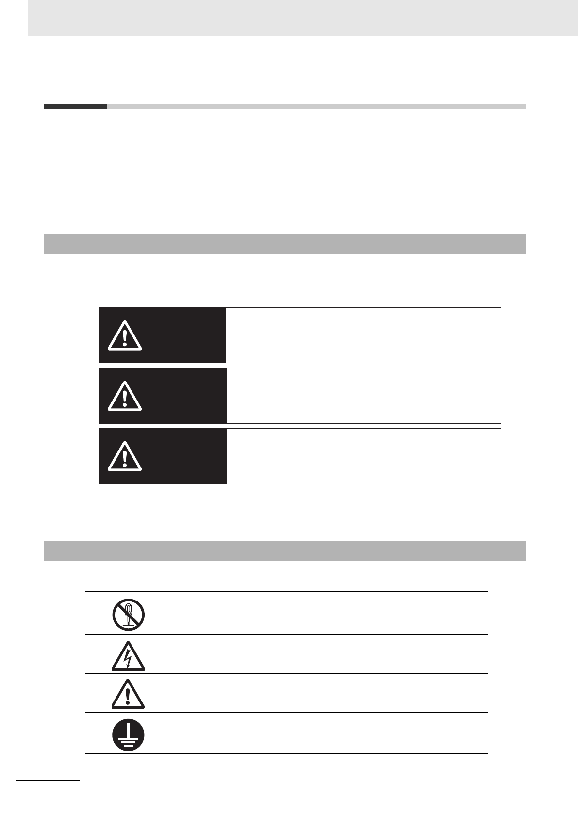
Safety Precautions
Indicates an imminently hazardous situation which, if
not avoided, is likely to result in serious injury or may
result in death. Additionally there may be severe
property damage.
Indicates a potentially hazardous situation which, if not
avoided, will result in minor or moderate injury, or may
result in serious injury or death. Additionally there may
be significant property damage.
DANGER
WARNING
Indicates a potentially hazardous situation which,
if not avoided, may result in minor or moderate
injury or in property damage.
Caution
Safety Precautions
• To ensure that the 1S-series Servomotor/Servo Drive Advance Type as well as peripheral equipment
are used safely and correctly, be sure to read this Safety Precautions section and the main text
before using the product. Learn all items you should know before use, regarding the equipment as
well as the required safety information and precautions.
• Make an arrangement so that this User’s Manual also gets to the end user of this product.
• After reading this User’s Manual, keep it in a convenient place so that it can be referenced at any
time.
Explanation of Displays
• The precautions indicated here provide important information for safety. Be sure to heed the information provided with the precautions.
• The following signal words are used to indicate and classify precautions in this User’s Manual.
Even those items denoted by the caution symbol may lead to a serious outcome depending on the situation. Accordingly, be sure to observe all safety precautions.
Explanation of Symbols
20
This User’s Manual uses the following symbols.
The circle and slash symbol indicates operations that you must not do.
The specific operation is shown in the circle and explained in text.
This example indicates prohibiting disassembly.
The triangle symbol indicates precautions and warnings.
The specific operation is shown in the triangle and explained in text.
This example indicates a precaution for electric shock.
The triangle symbol indicates precautions and warnings.
The specific operation is shown in the triangle and explained in text.
This example indicates a general precaution.
The filled circle symbol indicates operations that you must do.
The specific operation is shown in the circle and explained in text.
This example indicates a requirement for the ground.
1S-series with Built-in EtherCAT Communications and Safety Functionality User’s Manual (I621)
Page 23

Precautionary Information
WARNING
• Illustrations contained in this manual sometimes depict conditions without covers and safety shields
for the purpose of showing the details. When you use this product, be sure to install the covers and
shields as specified and use the product according to this manual.
• If the product has been stored for an extended period of time, contact your OMRON sales representative.
Handling of Safety Products
If the functions of safety products cannot attain their full potential, it will result in minor or moderate
injury, or may result in serious injury or death. When building the system, observe the following warnings and optimize safety product selection for your equipment and devices to ensure the integrity of the
safety-related components.
Safety Precautions
Setting Up a Risk Assessment System
The process of selecting these products should include the development and execution of a risk
assessment system early in the design development stage to help identify potential dangers in your
equipment and optimize safety product selection.
The following is an example of related international standards.
• ISO12100 General Principles for Design - Risk Assessment and Risk Reduction
Protective Measure
When developing a safety system for the equipment and devices that use safety products, make
every effort to understand and conform to the entire series of international and industry standards
available, such as the examples given below.
The following are examples of related international standards.
• ISO12100 General Principles for Design - Risk Assessment and Risk Reduction
• IEC60204-1 Electrical Equipment of Machines - Part 1: General Requirements
• ISO13849-1, -2 Safety-related Parts of Control Systems
• ISO14119 Interlocking Devices Associated with Guards - Principles for Design and Selection
• IEC/TS 62046 Application of Protective Equipment to Detect the Presence of Persons
Role of Safety Products
Safety products incorporate standardized safety functions and mechanisms, but the benefits of
these functions and mechanisms are designed to attain their full potential only within properly
designed safety-related systems. Make sure you fully understand all functions and mechanisms,
and use that understanding to develop systems that will ensure optimal usage.
The following are examples of related international standards.
• ISO14119 Interlocking Devices Associated with Guards - Principles for Design and Selection
• ISO13857 Safety Distances to Prevent Hazard Zones being Reached by Upper and Lower Limbs
1S-series with Built-in EtherCAT Communications and Safety Functionality User’s Manual (I621)
21
Page 24

Safety Precautions
WARNING
Installing Safety Products
Qualified engineers must develop your safety-related system and install safety products in devices
and equipment. Prior to machine commissioning, verify through testing that the safety products work
as expected.
The following are examples of related international standards.
• ISO12100 General Principles for Design - Risk Assessment and Risk Reduction
• IEC60204-1 Electrical Equipment of Machines - Part 1: General Requirements
• ISO13849-1, -2 Safety-related Parts of Control Systems
• ISO14119 Interlocking Devices Associated with Guards - Principles for Design and Selection
Observing Laws and Regulations
Safety products must conform to pertinent laws, regulations, and standards. Make sure that they are
installed and used in accordance with the laws, regulations, and standards of the country where the
devices and equipment incorporating these products are distributed.
Observing Usage Precautions
Carefully read the specifications and precautions as well as all items in the Instruction Manual for
your safety product to learn appropriate usage procedures. Any deviation from instructions will lead
to unexpected device or equipment failure not anticipated by the safety-related system.
Transferring Devices and Equipment
When you transfer devices and equipment, be sure to retain one copy of the Instruction Manual for
safety devices and the User’s Manual, and supply another copy with the device or equipment so the
person receiving it will have no problems with operation and maintenance.
The following are examples of related international standards.
• ISO12100 General Principles for Design - Risk Assessment and Risk Reduction
• IEC60204-1 Electrical Equipment of Machines - Part 1: General Requirements
• ISO13849-1, -2 Safety-related Parts of Control Systems
• IEC62061 Functional Safety of Safety-related Electrical, Electronic and Programmable Electronic
Control Systems
• IEC61508 Functional Safety of Electrical/Electronic/Programmable Electronic Safety-related Systems
Transporting and Unpacking
22
Do not damage, pull, or put excessive stress or heavy objects on the cables.
Doing so may cause electric shock, malfunction, or burning.
1S-series with Built-in EtherCAT Communications and Safety Functionality User’s Manual (I621)
Page 25
Safety Precautions
WARNING
Installation, Wiring and Maintenance
Install the Servo Drive, Servomotor, and peripheral equipment before wiring.
Not doing so may cause electric shock.
Be sure to ground the 200-VAC input model Servo Drive and Servomotor to 100 Ω or less,
and the 400-VAC input model to 10 Ω or less.
Not doing so may cause electric shock.
Do not remove the front cover, terminal covers, cables, or peripheral equipment while the
power is supplied.
Doing so may cause electric shock.
Before carrying out wiring or inspection, turn OFF the main circuit power and wait for at
least the following specific time.
Not doing so may cause electric shock or burning.
10 minutes: R88D-1SAN10F-ECT, R88D-1SAN15F-ECT, R88D-1SAN20F-ECT,
R88D-1SAN30F-ECT
20 minutes: R88D-1SAN02H-ECT, R88D-1SAN04H-ECT, R88D-1SAN08H-ECT,
R88D-1SAN10H-ECT, R88D-1SAN15H-ECT, R88D-1SAN20H-ECT,
R88D-1SAN30H-ECT
Do not damage, pull, or put excessive stress or heavy objects on the cables.
Doing so may cause electric shock, malfunction, or burning.
Use appropriate tools to wire terminals and connectors. Check that there is no short-circuit
before use.
Not doing so may cause electric shock.
Connect the frame ground wire in the integrated cable securely to or FG of the Servo
Drive.
Not doing so may cause electric shock.
Provide safety measures, such as a fuse, to protect against short circuiting of external wir-
ing and failure of the Servo Drive.
Not doing so may cause a fire.
Install the Servomotor, Servo Drive, and peripheral equipment on non-flammable materials
such as metals.
Not doing so may cause a fire.
Keep conductive or flammable foreign objects such as screws, metal pieces, and oil out of
the Servo Drive and connectors. The connector is set on the top of the Servo Drive. Pay
attention to mentioned earlier.
Not doing so may cause a fire or electric shock.
Design the configuration to cut off the main circuit power supply when the ERR signal (nor-
mally close contact) of the control output function is output (open).
Not doing so may cause a fire.
Do not bundle the integrated cables.
Not doing so may cause fire.
1S-series with Built-in EtherCAT Communications and Safety Functionality User’s Manual (I621)
23
Page 26

Safety Precautions
WARNING
WARNING
Lock the integrated cable and extension cable connectors.
Not doing so may cause fire.
Operation Check
Use the Servomotor, Servo Drive and integrated cable in a specified combination.
Not doing so may cause fire or equipment damage.
Usage
Do not enter the operating area during operation.
Doing so may cause injury.
Do not touch the Servo Drive radiator, Regeneration Resistor, or Servomotor while the
power is supplied or for a while after the power is turned OFF because they get hot.
Doing so may cause fire or a burn injury.
Take appropriate measures to ensure that the specified power with the rated voltage is supplied. Be particularly careful in locations where the power supply is unstable.
Not doing so may cause failure.
When the power is restored after a momentary power interruption, the machine may restart
suddenly. Do not come close to the machine when restoring power.
Implement measures to ensure safety of people nearby even when the machine is
restarted.
Doing so may cause injury.
Use appropriate tools to wire terminals and connectors. Check that there is no short-circuit
before use.
Not doing so may cause electric shock.
Be sure to observe the radiator plate installation conditions that are specified in the manual.
Not doing so may cause the Servo Drive or Servomotor to burn.
24
If the load that exceeds the allowable range is installed, it may cause the dynamic brake to
be damaged. Be sure to use the appropriate load. For the selection of the appropriate load,
refer to 4-5 Adjustment for Large Load Inertia on page 4-50.
Not doing so may cause the Servo Drive to be damaged.
The dynamic brake is intended for the stop at the time of an error and therefore it has a
short-time rating.
If the dynamic brake is activated, provide an interval of 3 minutes or more before the next
activation to prevent a circuit failure and burning of the Dynamic Brake Resistor.
1S-series with Built-in EtherCAT Communications and Safety Functionality User’s Manual (I621)
Page 27
Safety Precautions
Caution
Make a design of equipment with consideration of a distance until a Servomotor stops while
safety monitoring functions are used.
Not doing so may cause injury and equipment damage.
Do not place flammable materials near the Servomotor, Servo Drive, or peripheral equipment.
Not doing so may cause a fire.
If the Servo Drive fails, cut off the power supply to the Servo Drive at the power supply.
Not doing so may cause a fire.
Use an appropriate External Regeneration Resistor. Install an external protective device
such as temperature sensor to ensure safety when using the External Regeneration Resistor.
Not doing so run the risk of burnout.
Before operating the Servo Drive in an actual environment, check if it operates correctly
based on the newly set parameters.
Not doing so may cause equipment damage.
When constructing a system that includes safety functions, be sure you understand the rel-
evant safety standards and all related information in user documentation, and design the
system to comply with the standards.
Not doing so may cause injury or equipment damage.
Transporting and Unpacking
When transporting the Servo Drive, do not hold it by the cables, shield clamp, integrated
connector or motor shaft.
Injury or failure may result.
Do not step on the Servo Drive or place heavy articles on it.
Injury may result.
Do not overload the product. (Follow the instructions on the product label.)
Injury or failure may result.
Be sure to observe the specified amount when piling up products.
Injury or failure may result.
The allowable number of piled-up products Servo Drive, Servomotor, Reactor:
Follow the instructions on the individual package.
External Regeneration Resistor: 12
External Regeneration Resistance Unit: 4
Noise Filter: 15
1S-series with Built-in EtherCAT Communications and Safety Functionality User’s Manual (I621)
25
Page 28

Safety Precautions
Caution
Wiring
Be careful about sharp parts such as the corner of the equipment when handling the Servo
Drive and Servomotor.
Injury may result.
Precautions for Safe Use
General Precaution
• Do not store or install the Servo Drive in the following locations. Doing so may result in electric shock,
fire, equipment damage, or malfunction.
Locations subject to direct sunlight
Locations subject to temperatures outside the range specified in the specifications
Locations subject to humidity outside the range specified in the specifications
Locations subject to condensation as the result of severe changes in temperature
Locations subject to corrosive or flammable gases
Locations subject to dust (especially iron dust) or salts
Locations subject to exposure to water, oil, or chemicals
Locations subject to shock or vibration
• Medical electronics such as cardiac pacemakers may malfunction or injury may result.
• If an error occurs, remove the cause of the error and ensure safety, and then perform the error reset
and restart the operation. Injury, equipment damage, or burning may result.
Mounting
• A Regeneration Resistor or a Regeneration Unit gets hot while the power is supplied or for a while
after the power is turned OFF. In order to ensure safety, install an external protection such as a guard
so as not to touch them easily.
A burn injury may result.
Wiring
• Use a robot cable for the wiring to separately install the Servo Drive and Servomotor to moving and
fixed parts of the equipment. Equipment damage may result.
• Connect the Servo Drive to the Servomotor without a contactor, etc. Malfunction or equipment damage may result.
• Wire the cables correctly and securely. Runaway motor, Unintentional behavior of the brake, injury, or
failure may result.
• Take appropriate and sufficient countermeasures to provide shielding when installing systems in the
following locations. Failure may result.
Locations subject to static electricity or other forms of noise
Locations subject to strong electromagnetic fields
Locations subject to possible exposure to radioactivity
Locations close to power lines
26
1S-series with Built-in EtherCAT Communications and Safety Functionality User’s Manual (I621)
Page 29

• Do not move a integrated connector of a Servomotor over 5 times. Electric shock, equipment damage, or burning may result.
• Pay attention carefully to fingers where the levers of connectors are locked. Pinched fingers may
result.
Precautions for Correct Use
General Precaution
• When lifting a 20-kg or more Servo Drive during moving or installation, always have two people lift
the product by grasping a metal part other than the shaft or the integrated connector. Do not grasp a
plastic part. Injury or failure may result.
Relevant model: R88M-1AM2K715T-B, R88M-1AM3K015C-B
Transporting and Unpacking
• Check that the eye bolts are not loose after replacing them.
If they are loose, the screws can come off and the Servomotor may fall during the transportation by
the use of eye bolts. Do not put the human body under the Servomotor during the transportation.
Safety Precautions
Installation
• Be sure to observe the mounting direction. Failure may result.
• Provide the specified clearance between the Servo Drive and the inner surface of the control panel or
other equipment. Fire or failure may result.
• Do not apply strong impact on the motor shaft, integrated connector or Servo Drive. Failure may
result.
• Do not touch the key grooves with bare hands if the Servomotor with shaft-end key grooves is used.
Injury may result.
• Use non-magnetic mounting screws. Note also that the depth of any mounted screw does not reach
the effective thread length. Equipment damage may result.
• Be sure to observe the allowable axial load for the Servomotor. Equipment damage may result.
• Install equipment to prevent crash and reduce shock.
Do not run the Servomotor outside the operable range by the use of the drive prohibition function
such as overtravel. Crash against the stroke edge may occur depending on stopping distance and
equipment damage may result.
• Do not block the intake or exhaust openings. Do not allow foreign objects to enter the Servo Drive.
Fire may result.
Wiring
• Tighten the mounting screws, terminal block screws, and shield clamp screws for the Servo Drive
and Servomotor to the specified torque. Failure may result.
• Use crimp terminals to wire screw type terminal blocks. Do not connect bare stranded wires directly
to terminals blocks. Fire may result.
• Always use the power supply voltage specified in this document. Burning may result.
• Do not apply a commercial power supply directly to the Servomotor. Fire or failure may result.
• Disconnect all connections to the Servo Drive and Servomotor before attempting a megger test (insulation resistance measurement) on the Servo Drive or Servomotor. Not doing so may result in Servo
Drive or Servomotor failure. Do not perform a dielectric strength test on the Servo Drive or Servomotor. Doing so may result in damage of the internal elements.
• Carefully perform the wiring and assembling. Injury may result.
1S-series with Built-in EtherCAT Communications and Safety Functionality User’s Manual (I621)
27
Page 30

Safety Precautions
• Wear the protective equipment when installing or removing the main circuit connector, main circuit
connector A, main circuit connector B, control power supply connector, or motor connector. Do not
apply a force after the protrusion of the connector opener reaches the bottom dead center. (As a
guide, do not apply a force of 100 N or more.)
• Do not block the intake or exhaust openings. Do not allow foreign objects to enter the Servo Drive.
Fire may result.
• Be sure to install surge suppressors when you connect a load with an induction coil such as a relay to
the control output terminal. Malfunction or equipment damage may result.
• Do not give impact on connectors such as tapping by hammer. Damage may result.
• Be sure to install a shield clamp in accordance with a specified procedure. Electric shock may result.
Adjustment
• Install an immediate stop device externally to the machine so that the operation can be stopped and
the power supply is cut off immediately. Injury may result.
• Do not adjust or set parameters to extreme values, because it will make the operation unstable. Injury
may result.
• Secure a sufficient rigidity when you install a servo motor into equipment. Equipment damage or malfunction may result.
• If a problem occurs in serial communications or the computer during a test operation, you have no
means to stop the Servomotor.
Connect an externally installed emergency stop switch, etc. to the Error Stop Input of the general-purpose input so that the Servomotor can be stopped without fail.
• When using the Servomotor with key, run the Servomotor in a state in which the key cannot jump out
of the shaft.
Not doing so may result in hurting people around the equipment due to the jumping key.
Operation Check
• Fully check the shaft when you reset a brake interlock from PC tool.
• Do not drive the Servomotor by the use of an external drive source. Fire may result.
• Check the newly set parameters for proper execution before actually using them.
Usage
• Tighten the mounting screws, terminal block screws, and setting screws of a bracket of a shield
clamp for the Servo Drive, Servomotor, and peripheral equipment at the specified torque. Failure may
result.
• Install a stopping device on the machine to ensure safety.
The holding brake is not a stopping device to ensure safety. Injury may result.
• Install an immediate stop device externally to the machine so that the operation can be stopped and
the power supply is cut off immediately. Injury may result.
• Conduct a test operation after confirming that the equipment is not affected. Equipment damage may
result.
• Do not use the built-in brake of the Servomotor for normal braking operation. Failure may result.
• After an earthquake, be sure to conduct safety checks. Electric shock, injury, or fire may result.
• Connect an emergency stop (immediate stop) relay in series with the brake interlock output. Injury or
failure may result.
• Do not use the cable when it is laying in oil or water. Electric shock, injury, or fire may result.
• Install safety devices to prevent idling or locking of the electromagnetic brake or the gear head, or
leakage of grease from the gear head. Injury, damage, or taint damage result.
28
1S-series with Built-in EtherCAT Communications and Safety Functionality User’s Manual (I621)
Page 31

Safety Precautions
Location of warning
• Be sure to turn OFF the power supply when not using the Servo Drive for a prolonged period of time.
Not doing so may result in injury or malfunction.
• If the Servomotor is not controlled, it may not be possible to maintain the stop. To ensure safety,
install a stop device. Equipment damage or injury may result.
• Periodically run the Servomotor approximately one rotation when the oscillation operation continues
at a small angle of 45° or smaller. Servomotor failure may result.
• When a difference between a position indicated by the Servo Drive before the power supply OFF and
a position after the power supply ON is one rotation or more, check that devices are placed in appropriate areas.
• Immediately stop the operation and cut off the power supply when unusual smell, noise, smoking,
abnormal heat generation, or vibration occurs. Not doing so may result in Servo Drive or Servomotor
damage or burning.
Maintenance
• Cut off the power supply of equipment during maintenance. Not doing so may cause electric shock.
• After replacing the Servo Drive, transfer to the new Servo Drive all data needed to resume operation,
before restarting operation. Equipment damage may result.
• Do not repair the Servo Drive by disassembling it. Electric shock or injury may result.
Location of Warning Display
The Servo Drive bears a warning label at the following location to provide handling warnings.
When you handle the Servo Drive, be sure to observe the instructions provided on this label.
Instructions on Warning Display
1S-series with Built-in EtherCAT Communications and Safety Functionality User’s Manual (I621)
Note The above is an example of warning display.
29
Page 32

Safety Precautions
Dispose of in accordance with WEEE Directive
Disposal
Comply with the local ordinance and regulations when disposing of the product.
30
1S-series with Built-in EtherCAT Communications and Safety Functionality User’s Manual (I621)
Page 33

Items to Check After Unpacking
Name plate example: 200 VAC 1 kW Servo Drive
Servo Drive model
Servo Drive rating
Lot number and serial number
*1
Nameplate display location
Items to Check After Unpacking
After you unpack the product, check the following items.
• Is this the model you ordered?
• Was there any damage sustained during shipment?
Servo Drive
Nameplate of Servo Drive
The model, rating and lot number of the 1S-series Servo Drive are given on the product nameplate.
*1. The notifications and their meanings are explained below.
Notation: Lot No. DDMYY xxxx
DDMYY: Lot number, : For use by OMRON, xxxx: Serial number
“M” gives the month (1 to 9: January to September, X: October, Y: November, Z: December)
Accessories of Servo Drive
This product comes with the following accessories.
• INSTRUCTION MANUAL × 1 copy
• Warning label × 1 sheet
• General Compliance Information and instructions for EU × 1 copy
• Attached connectors (Depends on the model. Refer to the following table.)
1S-series with Built-in EtherCAT Communications and Safety Functionality User’s Manual (I621)
When UL/CSA certification is required, attach the warning label to a place around the Servo Drive.
31
Page 34

Items to Check After Unpacking
Connectors, mounting screws, mounting brackets, and other accessories other than those in the table
below are not supplied. They must be prepared by the customer.
If any item is missing or a problem is found such as Servo Drive damage, contact the OMRON dealer or
sales office where you purchased your product.
Specifications
Single-
phase/3-ph
ase 200
VAC
200 W
400 W
750 W
1.5 kW
1 kW
3-phase
200 VAC
2 kW
3 kW
1 kW
3-phase
400 VAC
1.5 kW
2 kW
3 kW
*1. The connector with 11 terminals is included. Two short-circuit wires are connected.
*2. The connector with 6 terminals is included. One short-circuit wire is connected.
*3. One opener is included.
Specifications
Single-
200 W
phase/3-ph
ase 200
VAC
750 W
1.5 kW
1 kW
3-phase
200 VAC
2 kW
3 kW
1 kW
3-phase
400 VAC
1.5 kW
2 kW
3 kW
*1. One short-circuit wire is connected to the connector.
*2. The connector with 3 terminals is included.
*3. The connector with 4 terminals is included.
*4. One opener is included.
Control I/O connector
Included
Main circuit connector B
--- Included
Included
---
Included
(CNB)
*1
*1
(CN1)
Brake interlock connector
(CN12)
Included
Motor connector
(CNC)
*2
Included
Included
Included
*3
*2
*3
Main circuit connector
and main circuit
connector A
(CNA)
Included
Included
Included
Included
*1 *3
*2 *3
*1 *3
*2 *3
Control power supply
connector (CND)
---400 W
Included
*4
---
Included
*4
32
1S-series with Built-in EtherCAT Communications and Safety Functionality User’s Manual (I621)
Page 35

Items to Check After Unpacking
Specifications
Safety signal
connector (CN14)
200 W
Single-pha
se/3-phase
200 VAC
400 W
750 W
1.5 kW
1 kW
3-phase
200 VAC
2 kW
Included
*1
Included
3 kW
1 kW
3-phase
400 VAC
1.5 kW
2 kW
3 kW
*1. Four short-circuit wires are connected to the connector. A pin to prevent
improper wiring are included.
Safe brake
control connector
(CN15)
1S-series with Built-in EtherCAT Communications and Safety Functionality User’s Manual (I621)
33
Page 36

Items to Check After Unpacking
R88M-1AM3K015C-BOS2
10150700003
400 VAC 8.5 A
100 Hz
22 kg
3.0 kW
1500
Nameplate display location
From the left,
Rated rotation speed
(Example: 1,500 r/min)
Rated frequency (Example: 100 Hz)
Motor weight (Example: 22 kg)
*1
*1. The weight is not given for the Servomotor with a flange size of
80 x 80 or less.
From the left,
Number of phases (Example: 3)
Rated voltage
(Example: 400 VAC)
Rated current
(Example: 8.5 A)
Rated output
(Example: 3.0 kW)
From the left,
Insulation class (Example: F)
Totally enclosed protection
type motor (Example: TE)
Operating ambient
temperature (Example: 40°C)
Protective structure
(Example: IP67)
Motor model
Serial number
Servomotor
Nameplate of Servomotor
The model, rating and serial number of the 1S-series Servomotor are given on the product nameplate.
Accessories of Servomotor
This product comes with an instruction manual.
34
1S-series with Built-in EtherCAT Communications and Safety Functionality User’s Manual (I621)
Page 37

Decelerator (Backlash: 3 Arcminutes Max.)
HPG-14A-05-J2AXT
ΧΧ-ΧΧΧΧΧΧΧ-ΧΧΧ
Upper row: Model on nameplate
Lower row: Serial No. (the OMRON logo at the end)
The model on nameplate HPG-14A-05-J2AXT
corresponds to the decelerator model HPG14A05200B.
For Decelerators (backlash: 3 arcminutes max.), the model number given on the nameplate does not
match the model number of the Decelerator. Therefore, refer to the following table for correspondence
between the model numbers on nameplates and Decelerators.
Example of nameplate: 200-W Decelerator (backlash: 3 arcminutes max., reduction ratio: 1/5) for
3,000-r/min Servomotors
Items to Check After Unpacking
1S-series with Built-in EtherCAT Communications and Safety Functionality User’s Manual (I621)
35
Page 38

Items to Check After Unpacking
Decelerator (backlash: 3 arcminutes max.) for 3,000-r/min Servomotors
Specifications Without key With key and tap
Servo-
motor
rated
output
200 W
400 W
750 W
(200 V)
750 W
(400 V)
1 kW
1.5 kW
Reduc-
tion
ratio
1/5
1/11
1/21
1/33
1/45
1/5
1/11
1/21
1/33
1/45
1/5
1/11
1/21
1/33
1/45
1/5
1/11
1/21
1/33
1/5
1/11
1/21
1/5
1/11
1/21
Decelerator model Model on nameplate Decelerator model Model on nameplate
R88GHPG14A05200B
R88GHPG14A11200B
R88GHPG20A21200B
R88GHPG20A33200B
R88GHPG20A45200B
R88GHPG14A05400B
R88GHPG20A11400B
R88GHPG20A21400B
R88GHPG32A33400B
R88GHPG32A45400B
R88GHPG20A05750B
R88GHPG20A11750B
R88GHPG32A21750B
R88GHPG32A33750B
R88GHPG32A45750B
R88GHPG32A052K0B
R88GHPG32A112K0B
R88GHPG32A211K5B
R88GHPG32A33600SB
R88GHPG32A052K0B
R88GHPG32A112K0B
R88GHPG32A211K5B
R88GHPG32A052K0B
R88GHPG32A112K0B
R88GHPG32A211K5B
HPG-14A-05-J2AXT R88G-
HPG14A05200BJ
HPG-14A-11-J2AXU R88G-
HPG14A11200BJ
HPG-20A-21-J2GDH R88G-
HPG20A21200BJ
HPG-20A-33-J2GDI R88G-
HPG20A33200BJ
HPG-20A-45-J2GDI R88G-
HPG20A45200BJ
HPG-14A-05-J2AXW R88G-
HPG14A05400BJ
HPG-20A-11-J2GDK R88G-
HPG20A11400BJ
HPG-20A-21-J2GDK R88G-
HPG20A21400BJ
HPG-32A-33-J2NELA R88G-
HPG32A33400BJ
HPG-32A-45-J2NELA R88G-
HPG32A45400BJ
HPG-20A-05-J2FFO R88G-
HPG20A05750BJ
HPG-20A-11-J2FFP R88G-
HPG20A11750BJ
HPG-32A-21-J2NAI R88G-
HPG32A21750BJ
HPG-32A-33-J2NAJ R88G-
HPG32A33750BJ
HPG-32A-45-J2NAJ R88G-
HPG32A45750BJ
HPG-32A-05-J2NFG R88G-
HPG32A052K0BJ
HPG-32A-11-J2NFH R88G-
HPG32A112K0BJ
HPG-32A-21-J2NFI R88G-
HPG32A211K5BJ
HPG-32A-33-J2NFJ R88G-
HPG32A33600SBJ
HPG-32A-05-J2NFG R88G-
HPG32A052K0BJ
HPG-32A-11-J2NFH R88G-
HPG32A112K0BJ
HPG-32A-21-J2NFI R88G-
HPG32A211K5BJ
HPG-32A-05-J2NFG R88G-
HPG32A052K0BJ
HPG-32A-11-J2NFH R88G-
HPG32A112K0BJ
HPG-32A-21-J2NFI R88G-
HPG32A211K5BJ
HPG-14A-05-J6AXT
HPG-14A-11-J6AXU
HPG-20A-21-J6GDH
HPG-20A-33-J6GDI
HPG-20A-45-J6GDI
HPG-14A-05-J6AXW
HPG-20A-11-J6GDK
HPG-20A-21-J6GDK
HPG-32A-33-J6NELA
HPG-32A-45-J6NELA
HPG-20A-05-J6FFO
HPG-20A-11-J6FFP
HPG-32A-21-J6NAI
HPG-32A-33-J6NAJ
HPG-32A-45-J6NAJ
H
PG-32A-05-J6NFG
HPG-32A-11-J6NFH
HPG-32A-21-J6NFI
HPG-32A-33-J6NFJ
HPG-32A-05-J6NFG
HPG-32A-11-J6NFH
HPG-32A-21-J6NFI
HPG-32A-05-J6NFG
HPG-32A-11-J6NFH
HPG-32A-21-J6NFI
36
1S-series with Built-in EtherCAT Communications and Safety Functionality User’s Manual (I621)
Page 39

Items to Check After Unpacking
Specifications Without key With key and tap
Servo-
motor
rated
output
2 kW
2.6 kW
(200 V)
3 kW
Reduc-
tion
ratio
1/5
1/11
1/5
Decelerator model Model on nameplate Decelerator model Model on nameplate
R88GHPG32A052K0B
R88GHPG32A112K0B
R88GHPG32A053K0B
HPG-32A-05-J2NFG R88G-
HPG32A052K0BJ
HPG-32A-11-J2NFH R88G-
HPG32A112K0BJ
HPG-32A-05-J2MCK R88G-
HPG32A053K0BJ
HPG-32A-05-J6NFG
HPG-32A-11-J6NFH
HPG-32A-05-J6MCK
(400 V)
Decelerator (backlash: 3 arcminutes max.) for 1,500-r/min Servomotors
Specifications Without key With key and tap
Servo-
motor
rated
output
1.5 kW
2.7 kW
(200 V)
3 kW
(400 V)
Reduc-
tion
ratio
1/5
1/11
1/21
1/33
1/5
1/11
1/20
1/25
Decelerator model Model on nameplate Decelerator model Model on nameplate
R88GHPG32A053K0B
R88GHPG32A112K0SB
R88GHPG50A21900TB
R88GHPG50A33900TB
R88GHPG50A055K0SB
R88GHPG50A115K0SB
R88GHPG65A205K0SB
R88GHPG65A255K0SB
HPG32A-05-J2MCK
HPG32A-11-J2MCL
HPG50A-21-J2BADB
HPG50A-33-J2BADB
HPG50A-05-J2EBCH
HPG50A-11-J2EBDH
HPG65A-20-J2EBCH
HPG65A-25-J2EBCH
R88GHPG32A053K0BJ
R88GHPG32A112K0SBJ
R88GHPG50A21900TBJ
R88GHPG50A33900TBJ
R88GHPG50A055K0SBJ
R88GHPG50A115K0SBJ
R88GHPG65A205K0SBJ
R88GHPG65A255K0SBJ
HPG32A-05-J6MCK
HPG32A-11-J6MCL
HPG50A-21-J6BADB
HPG50A-33-J6BADB
HPG50A-05-J6EBCH
HPG50A-11-J6EBDH
HPG65A-20-J6EBCH
HPG65A-25-J6EBCH
1S-series with Built-in EtherCAT Communications and Safety Functionality User’s Manual (I621)
37
Page 40

Items to Check After Unpacking
Decelerator (Backlash: 15 Arcminutes Max.)
For Decelerators (backlash: 15 arcminutes max.), the product nameplate indicates the model number,
rated output, reduction ratio, serial number, and date of manufacture.
Decelerator model number
R88G-
Rated output
(Example: 200 W)
GEAR
POWER
LOT NO.
DATE
VRXF05B200CJ
200
W
XXXXXXXXX
XXXX.XX
RATIO
1:5
Reduction ratio
(Example: 1/5)
Serial number
Date of manufacture
(Rubber cap)
Nameplate display location
(Rubber cap side)
OMRON Corporation
MADE IN CHINA
Integrated Cable
The following product models come with a shield clamp. The shield clamp is used for mounting to a
Servo Drive. Keep it until the use.
As for a shield clamp, refer to Shield Clamp Bracket on page 2-18.
Shield Clamp
This product comes with two screws (M4×12) for mounting.
38
1S-series with Built-in EtherCAT Communications and Safety Functionality User’s Manual (I621)
Page 41

Related Manuals
Related Manuals
The following are the manuals related to this manual. Use these manuals for reference.
Manual name Cat. No. Model numbers Application Description
NX-series CPU
Unit Hardware
User’s Manual
NJ-series CPU
Unit Hardware
User’s Manual
W535 NX701- Learning the basic speci-
fications of the NX-series
CPU Units, including
introductory information,
designing, installation,
and maintenance.
Mainly hardware information is provided.
W500 NJ501-
NJ301-
NJ101-
Learning the basic specifications of the NJ-series
CPU Units, including
introductory information,
designing, installation,
and maintenance.
Mainly hardware information is provided.
An introduction to the entire
NX-series system is provided along with the following information on the CPU
Unit.
• Features and system configuration
• Introduction
• Part names and functions
• General specifications
• Installation and wiring
• Maintenance and inspection
Use this manual together
with the NJ/NX-series CPU
Unit Software User’s Manual
(Cat. No. W501).
An introduction to the entire
NJ-series system is provided
along with the following information on the CPU Unit.
• Features and system configuration
• Introduction
• Part names and functions
• General specifications
• Installation and wiring
• Maintenance and inspection
Use this manual together
with the NJ/NX-series CPU
Unit Software User’s Manual
(Cat. No. W501).
1S-series with Built-in EtherCAT Communications and Safety Functionality User’s Manual (I621)
39
Page 42

Related Manuals
Manual name Cat. No. Model numbers Application Description
NY-series
IPC Machine
Controller
Industrial Box PC
Hardware User’s
Manual
NY-series
IPC Machine
Controller
Industrial Panel
PC
Hardware User’s
Manual
NJ/NX-series CPU
Unit Software
User’s Manual
W556 NY512- Learning the basic
information about IPC
Machine Controller
Industrial Box PCs. The
basic information related
to installation, usage
procedures, and
maintenance is included.
Mainly hardware
information is provided.
W557 NY532- Learning the basic
information about IPC
Machine Controller
Industrial Panel PCs.
The basic information
related to installation,
usage procedures, and
maintenance is included.
Mainly hardware
information is provided.
W501 NX701-
NX102-
NX1P2-
NJ501-
NJ301-
NJ101-
Learning how to program
and set up an
NJ/NX-series CPU Unit.
Mainly software information is provided.
An introduction to the entire
IPC Machine Controller
system is provided along
with the following
information.
• Introduction
• System configuration
• Specifications
• Installation
• Usage procedures
• Maintenance
Use this manual together
with the NY-series IPC
Machine Controller Industrial Panel PC / Industrial
Box PC Software User’s
Manual (Cat. No. W558).
The following information is
provided on a Controller built
with an NJ/NX-series CPU
Unit.
• CPU Unit operation
• CPU Unit features
• Initial settings
• Programming based on
IEC 61131-3 language
specifications
Use this manual together
with the NX-series CPU Unit
Hardware User’s Manual
(Cat. No. W535) or NJ-series
CPU Unit Hardware User’s
Manual (Cat. No. W500).
40
1S-series with Built-in EtherCAT Communications and Safety Functionality User’s Manual (I621)
Page 43

Related Manuals
Manual name Cat. No. Model numbers Application Description
NJ/NX-series CPU
Unit
Built-in EtherCAT® Port
User’s Manual
NY-series
IPC Machine
Controller
Industrial Panel
PC / Industrial Box
PC
Software User’s
Manual
NX-series
NX102 CPU Unit
Hardware User’s
Manual
W505 NX701-
NX102-
NX1P2-
NJ501-
NJ301-
NJ101-
W558 NY532-
NY512-
W593 NX102- Learning the basic
Learning how to configure the EtherCAT communications system.
Learning how to program
IPC Machine Controller
functions and set up a
system in the NY-series
Machine Controller.
specifications of the
NX102 CPU Units,
including introductory
information, designing,
installation, and
maintenance.
Mainly hardware
information is provided.
Describes setup procedures
for building the EtherCAT
communications system.
The following information is
provided on a Machine
Controller.
• Controller operation
• Controller features
• Controller settings
• Programming based on
IEC 61131-3 language
specifications
Use this manual together
with the NY-series IPC
Machine Controller Industrial Panel PC Hardware
User’s Manual (Cat. No.
W557) or NY-series IPC
Machine Controller Industrial Box PC Hardware
User’s Manual (Cat. No.
W556).
An introduction to the entire
NX102 system is provided
along with the following
information on the CPU Unit.
• Features and system
configuration
• Introduction
• Part names and functions
• General specifications
• Installation and wiring
• Maintenance and
inspection
Use this manual together
with the NJ/NX-series CPU
Unit Software User’s Manual
(Cat. No. W501).
1S-series with Built-in EtherCAT Communications and Safety Functionality User’s Manual (I621)
41
Page 44

Related Manuals
Manual name Cat. No. Model numbers Application Description
NX-series NX1P2
CPU Unit Hardware User's Manual
NJ/NX-series CPU
Unit Motion Control User’s Manual
NY-series
IPC Machine
Controller
Industrial Panel
PC / Industrial Box
PC
Motion Control
User’s Manual
NX-series Safety
Control Units
User's Manual
NX-series Safety
Control Unit
Instructions Reference Manual
Sysmac Studio
Version 1 Operation Manual
Sysmac Studio
Drive Functions
Operation Manual
SYSMAC
CJ-series Position
Control Unit Operation Manual
W578 NX1P2- Learning the basic speci-
fications of the NX-series
NX1P2 CPU Units,
including introductory
information, designing,
installation, and maintenance.
Mainly hardware information is provided.
W507 NX701-
NX102-
NX1P2-
NJ501-
NJ301-
NJ101-
W559 NY532-
NY512-
Z930 NX-SL
NX-SI
NX-SO
Z931 NX-SL Learning the command
W504 SYSMAC-SE2
I589 SYSMAC-SE2
W487 CJ1W-NC281
CJ1W-NC481
CJ1W-NC881
CJ1W-NCF81
CJ1W-NC482
CJ1W-NC882
CJ1W-NCF82
Learning about motion
control settings and programming concepts.
Learning about motion
control settings and
programming concepts
related to the NY-series
IPC Machine Controller.
Learning how to use the
NX-series Safety Control Units.
specifications of the
safety CPU Units.
Learning about the operating procedures and
functions of the Sysmac
Studio.
Learning how to set up
and adjust the Servo
Drives.
Learning about the NC
Units (CJ1W-NC281/
481/ 881/ F81/ 482/ 882/
F82).
An introduction to the entire
NX1P2 CPU Unit system is
provided along with the following information on the
NX1P2 CPU Unit.
• Features and system configuration
• Introduction
• Part names and functions
• General specifications
• Installation and wiring
• Maintenance and inspection
Use this manual together
with the NJ/NX-series CPU
Unit Software User’s Manual
(Cat. No. W501).
The settings and operation of
the CPU Unit and programming concepts for motion
control are described.
The settings and operation of
the Controller and
programming concepts for
motion control are described.
Describes the hardware,
setup methods and functions
of the NX-series Safety Control Units.
Information about commands for safety CPU unit is
provided.
Describes the operating procedures of the Sysmac Studio.
Describes the operating procedures of the Sysmac Studio.
Describes the setup methods and operating procedures of the NC Units.
42
1S-series with Built-in EtherCAT Communications and Safety Functionality User’s Manual (I621)
Page 45

Related Manuals
Manual name Cat. No. Model numbers Application Description
G9SP-series
Safety Controller
Operation Manual
Z922 G9SP-N10S
G9SP-N10D
G9SP-N20S
Learning how to use the
G9SP-series safety Controllers.
Describes the hardware,
setup methods and functions
of the G9SP-series safety
Controllers.
1S-series with Built-in EtherCAT Communications and Safety Functionality User’s Manual (I621)
43
Page 46

Terminology
Terminology
Ter m
Cable Redundancy Function --- A function to continue communications with Ether-
CAN application protocol over EtherCAT CoE A CAN application protocol service implemented on
CAN in Automation CiA CiA is the international users’ and manufacturers’
Device Profile --- Collection of device dependent information and func-
Distributed Clocks DC Method to synchronize slaves and maintain a global
EtherCAT Slave Controller ESC A controller for EtherCAT slave communication.
EtherCAT Slave Information ESI An XML file that contains setting information for an
EtherCAT State Machine ESM An EtherCAT communication state machine.
EtherCAT Technology Group ETG The ETG is a global organization in which OEM, End
Fieldbus Memory Management Unit FMMU Single element of the fieldbus memory management
Index --- Address of an object within an application process.
Instance --- When there are the several same functions inde-
Object --- Abstract representation of a particular component
Object Dictionary OD Data structure addressed by Index and Subindex
Physical Device Internal Interface PDI A series of elements to access data link services
Power Drive System PDS A power drive system consisting of a Servo Drive, an
Process Data --- Collection of application objects designated to be
Process Data Object PDO Structure described by mapping parameters that
Receive PDO RxPDO A process data object received by an EtherCAT
Abbrevi-
ation
Description
CAT slaves even if a communications cable is broken in the EtherCAT communications path.
EtherCAT.
group that develops and supports higher-layer protocols.
tionality providing consistency between similar
devices of the same device type.
time base.
EtherCAT slave.
Users and Technology Providers join forces to support and promote the further technology development.
unit: one correspondence between a coherent logical address space and a coherent physical memory
location.
pendently in objects, each object is called as an
instance.
For example, there are eight instances SS1 command 1 to SS1 command 8 in SS1 command.
within a device, which consists of data, parameters,
and methods.
that contains description of data type objects, communication objects and application objects.
from the application layer.
inverter, and other components.
transferred cyclically or acyclically for the purpose of
measurement and control.
contain one or several process data entities.
slave.
44
1S-series with Built-in EtherCAT Communications and Safety Functionality User’s Manual (I621)
Page 47

Terminology
Ter m
Ring Disconnection Status --- A status in which communications continue even if
safe state --- The status of a device or piece of equipment when
safety control --- A type of control that uses devices, functions, and
Safety Controller --- Generic terms of a controller to perform safety con-
Safety Current Position --- It is a position data that are assured in functional
Safety Current Pulse Position --- It is a position data that are assured in functional
Safety over EtherCAT FSoE A system to communicate for the functional safety
safety process data communications --- A type of I/O data communications that is used for
safety reaction time --- The time required for the system to enter a safe state
Safety Related Application Parameter SRA
Service Data Object SDO CoE asynchronous mailbox communications where
Slave Information Interface SII Slave information stored in the nonvolatile memory
standard control --- A type of control that use devices, functions, and
Standard Controller --- Generic terms of a controller to perform standard
Abbrevi-
ation
Parame-
ter
Description
an EtherCAT physical layer link is disconnected in a
ring topology on the EtherCAT system.
the risk of danger to humans has been reduced to an
acceptable level.
data that are designed with special safety measures.
trol
safety.
The position data of 32 bit is set as Safety Original
Position “Zero”. The position data of single rotation
can be read at 20 bit. While the upper 13 bit can be
used, the lower 7 bit cannot be assured.
safety.
The position data of 32 bit is set as a base position
that is obtained from encoder. The position data of
single rotation can be read at 20 bit. While the upper
13 bit can be used, the lower 7 bit cannot be
assured. The data is read inside a Servo Drive while
a safety origin position is fixed or SOS function is
monitoring a position.
over EtherCAT.
safety control purposes.
in a worst-case scenario after the occurrence of a
safety-related input (press of an emergency stop
pushbutton switch, interruption of a light curtain,
opening of a safety door, etc.) or device failure.
The reaction time of the system includes the reaction
times of sensors and actuators, just like the reaction
time for a Controller or network.
Indicates objects related to the safety functions.
Set the parameter by the setting tool of the safety
controller. The parameter is retained by the safety
controller. The data attribute of objects is [S].
For more information, refer to 9-1 Object Description
Format on page 9-5.
all objects in the object dictionary can be read and
written.
of each slave.
data that are designed for general control purposes.
This term is used to differentiate from a safety control.
control
1S-series with Built-in EtherCAT Communications and Safety Functionality User’s Manual (I621)
45
Page 48

Terminology
Ter m
Abbrevi-
ation
Description
Subindex --- Sub-address of an object within the object dictionary.
Sync Manager SM Collection of control elements to coordinate access
to concurrently used objects.
Transmit PDO TxPDO A process data object sent from an EtherCAT slave.
46
1S-series with Built-in EtherCAT Communications and Safety Functionality User’s Manual (I621)
Page 49

Revision History
Cat. No.
I621-E1-03
Revision code
The manual revision code is a number appended to the end of the catalog number found in the front
and back cover.
Example
Revision History
Revision
code
01 June 2020 Original production
02 November 2020 • Made changes accompanying the support of cable redundancy
03 March 2021 Corrected mistakes.
Date Revised content
function.
• Corrected mistakes.
1S-series with Built-in EtherCAT Communications and Safety Functionality User’s Manual (I621)
47
Page 50

Revision History
48
1S-series with Built-in EtherCAT Communications and Safety Functionality User’s Manual (I621)
Page 51

Features and System Configuration
This section explains the features of the Servo Drive and name of each part.
1-1 Outline . . . . . . . . . . . . . . . . . . . . . . . . . . . . . . . . . . . . . . . . . . . . . . . . . . . . . . . 1-2
1-1-1 Features of 1S-series Servo Drive Advance Type . . . . . . . . . . . . . . . . . . . . . 1-2
1-1-2 EtherCAT . . . . . . . . . . . . . . . . . . . . . . . . . . . . . . . . . . . . . . . . . . . . . . . . . . . . 1-3
1-1-3 Object Dictionary . . . . . . . . . . . . . . . . . . . . . . . . . . . . . . . . . . . . . . . . . . . . . . 1-4
1-2 System Configuration . . . . . . . . . . . . . . . . . . . . . . . . . . . . . . . . . . . . . . . . . . 1-5
1-3 Names and Functions . . . . . . . . . . . . . . . . . . . . . . . . . . . . . . . . . . . . . . . . . . 1-6
1-3-1 Servo Drive Part Names . . . . . . . . . . . . . . . . . . . . . . . . . . . . . . . . . . . . . . . . . 1-6
1-3-2 Servo Drive Functions . . . . . . . . . . . . . . . . . . . . . . . . . . . . . . . . . . . . . . . . . 1-10
1-3-3 Servomotor Part Names . . . . . . . . . . . . . . . . . . . . . . . . . . . . . . . . . . . . . . . . 1-13
1-3-4 Servomotor Functions . . . . . . . . . . . . . . . . . . . . . . . . . . . . . . . . . . . . . . . . . 1-15
1-3-5 Shield Clamp Part Names . . . . . . . . . . . . . . . . . . . . . . . . . . . . . . . . . . . . . . 1-16
1-4 System Block Diagram . . . . . . . . . . . . . . . . . . . . . . . . . . . . . . . . . . . . . . . . 1-17
1
1-5 Applicable Standards . . . . . . . . . . . . . . . . . . . . . . . . . . . . . . . . . . . . . . . . . 1-21
1-5-1 EU Directives . . . . . . . . . . . . . . . . . . . . . . . . . . . . . . . . . . . . . . . . . . . . . . . . 1-21
1-5-2 UL and cUL Standards . . . . . . . . . . . . . . . . . . . . . . . . . . . . . . . . . . . . . . . . . 1-22
1-5-3 Korean Radio Regulations (KC) . . . . . . . . . . . . . . . . . . . . . . . . . . . . . . . . . . 1-23
1-5-4 SEMI F47 . . . . . . . . . . . . . . . . . . . . . . . . . . . . . . . . . . . . . . . . . . . . . . . . . . . 1-23
1-5-5 Australian EMC Labeling Requirements (RCM) . . . . . . . . . . . . . . . . . . . . . . 1-23
1-5-6 EAC Requirements . . . . . . . . . . . . . . . . . . . . . . . . . . . . . . . . . . . . . . . . . . . . 1-23
1-6 Unit Versions . . . . . . . . . . . . . . . . . . . . . . . . . . . . . . . . . . . . . . . . . . . . . . . . 1-24
1-6-1 Confirmation Method . . . . . . . . . . . . . . . . . . . . . . . . . . . . . . . . . . . . . . . . . . 1-24
1-6-2 Unit Versions and Sysmac Studio Versions . . . . . . . . . . . . . . . . . . . . . . . . . 1-24
1-7 Procedures to Start Operation . . . . . . . . . . . . . . . . . . . . . . . . . . . . . . . . . . 1-25
1-7-1 Overall Procedure . . . . . . . . . . . . . . . . . . . . . . . . . . . . . . . . . . . . . . . . . . . . . 1-25
1-7-2 Procedure Details . . . . . . . . . . . . . . . . . . . . . . . . . . . . . . . . . . . . . . . . . . . . . 1-27
1S-series with Built-in EtherCAT Communications and Safety Functionality User’s Manual (I621)
1 - 1
Page 52

1 Features and System Configuration
1-1 Outline
The 1S-series Servo Drives Advance Type with Built-in EtherCAT Communications are provided with 8
safety functions and support 100-Mbps EtherCAT.
When you use the 1S-series Servo Drive with a Machine Automation Controller NJ/NX-series CPU
Unit, NY-series IPC Machine Controller, or Position Control Unit with EtherCAT (Model:
CJ1W-NC8), you can construct a high-speed and sophisticated positioning control system.
You need only one communications cable to connect the Servo Drive and the Controller, and also only
one cable to connect the Servo Drive and the Servomotor.
With adjustment functions, adaptive notch filter, notch filter, and damping control, you can set up a system that provides stable operation by suppressing vibration in low-rigidity machines.
Moreover, with the two-degree-of-freedom (TDF) control structure, you can easily adjust high-precision
positioning.
1-1-1 Features of 1S-series Servo Drive Advance Type
The 1S-series Servo Drives Advance Type have the following features.
Realization of Safer Equipment and More Efficient Production
The following eight safety functions that comply with the SIL3/PLe functional safety levels are provided:
STO, SS1, SS2, SOS, SLS, SLP, SDI, and SBC. This product can improve not only equipment safety
but also production efficiency by shortening production facility downtime.
By using it with other OMRON safety products, a device can be designed more easily.
Use of only One Cable for the Motor, Encoder, and Brake
One Cable Technology is adopted for the cable connecting the Servo Drive and the Servomotor, unifying the three cables for supply of power to the motor, the encoder, and the brake into one cable.
This economization of wiring and space can downsize a device and reduce design and maintenance
work.
Optimal Functionality and Operability by Standardizing Specifications
As a Sysmac Device, the 1S-series Servo Drive Advance Type with built-in EtherCAT communications
is designed to achieve optimum functionality and ease of operation when it is used together with the
NJ/NX-series Machine Automation Controller, NY-series IPC Machine Controller, and the Sysmac Studio Automation Software.
Sysmac Device is a generic term for OMRON control devices such as an EtherCAT Slave, designed
with unified communications specifications and user interface specifications.
1 - 2
Data Transmission Using EtherCAT Communications
Combining the 1S-series Servo Drive with a Machine Automation Controller NJ/NX-series CPU Unit,
NY-series IPC Machine Controller, or Position Control Unit with EtherCAT (Model: CJ1W-NC8)
enables you to exchange all position information with the controller in high-speed data communications.
Since the various control commands are transmitted via data communications, Servomotor’s operational performance is maximized without being limited by interface specifications such as the response
frequency of the encoder feedback pulses.
1S-series with Built-in EtherCAT Communications and Safety Functionality User’s Manual (I621)
Page 53

1 Features and System Configuration
You can use the Servo Drive’s various control parameters and monitor data on a host controller, and
unify the system data for management.
EtherCAT Communications Cycle of 125 µs
Combination with an NX7 Machine Automation Controller enables high-speed and high-precision
motion control at the communications cycle of 125 µs.
1-1 Outline
High Equipment Utilization Efficiency with 400-V Models
The 400-V models are provided for use with large equipment, at overseas facilities and in wide-ranging
applications and environment. Since the utilization ratio of facility equipment also increases, the TCO
(Total Cost of Ownership) will come down.
Achievement of Safety on EtherCAT Network
You can use NX-series Safety Control Units to integrate safety controls in a sequence and motion control system.
The 1S-series Servo Drives Advance Type support the FSoE (Safety over EtherCAT) protocol as the
safety communications. You can build the safety system that uses the safety functions from the safety
controller on the EtherCAT network.
Suppressing Vibration of Low-rigidity Machines During Acceleration/Deceleration
The damping control function suppresses vibration of low-rigidity machines or devices whose tips tend
to vibrate. The function can also be used for damping control for larger constructions as it supports
vibration ranging from 0.5 to 300 Hz. You can maximize the performance of the Servomotor by
adjusting the trade-off between the damping time and the amount of peak control.
Easy Adjustment with TDF Control Structure
1
1-1-2 EtherCAT
The TDF control structure allows you to separately adjust the amount of overshooting and the
resistance against disturbance. With this feature, you can easily achieve high-precision positioning,
which is difficult to achieve with the one-degree-of-freedom (ODF) control.
1-1-2 EtherCAT
EtherCAT is an open high-speed industrial network system that conforms to Ethernet (IEEE 802.3).
Each node achieves a short communications cycle time by transmitting Ethernet frames at high speed.
A mechanism that allows sharing clock information enables high-precision synchronization control with
low communications jitter.
1S-series with Built-in EtherCAT Communications and Safety Functionality User’s Manual (I621)
1 - 3
Page 54

1 Features and System Configuration
1-1-3 Object Dictionary
1S-series Servo Drives Advance Type with Built-in EtherCAT Communications use the object dictionary
for CAN application protocol over EtherCAT (CoE) as a base for communications.
An object is an abstract representation of a particular component within a device, which consists of
data, parameters, and methods.
An object dictionary is a data structure that contains description of data type objects, communication
objects and application objects.
All objects are assigned four-digit hexadecimal indexes in the areas shown in the following table.
Index (hex) Area Description
0000 to 0FFF Data Type Area Definitions of data types.
1000 to 1FFF CoE Communications Area Definitions of objects that can be used by all serv-
2000 to 2FFF Manufacturer Specific Area 1 Objects with common definitions for all OMRON
3000 to 5FFF Manufacturer Specific Area 2 Objects with common definitions for all 1S-series
6000 to DFFF Device Profile Area Variables defined in the Servo Drive’s CiA402 drive
E000 to EFFF Device Profile Area 2 Objects defined in the Servo Drive’s FSoE CiA402
F000 to FFFF Device Area Objects defined in a device.
*1. For details on servo parameters, refer to Section 9 Details on Servo Parameters.
ers for designated communications.
products.
Servo Drives (servo parameters).
profile.
slave connection.
*1
1 - 4
1S-series with Built-in EtherCAT Communications and Safety Functionality User’s Manual (I621)
Page 55

1 Features and System Configuration
ID211
0
1
3
2
4
5
7
6
8
9
11
10
12
13
14
15
DC24V
7
mA
COM
MA
C
H
No
.
AD042
RUN
E
R
C
ERH
B
1 A
1
x1
0
1
x1
0
0
0
9
8
7
6
5
4
3
2
1
0
9
8
7
6
5
4
3
2
1
0 12345
67
8
9
1
0
1
1
1
21
3
1
4
1
5
EtherCAT
Position Control Unit
CJ1W-NC8
Programmable Controller
CJ-series
Machine Automation Controller
NJ/NX-series
1S-series
Servo Drive
Advance Type
R88D-1SAN-ECT
1S-series
Servomotor
Advance Type
R88M-1AL/-1AM
Controller (EtherCAT type)
IPC Machine Controller
NY-series
1-2 System Configuration
The system configuration for a 1S-series Servo Drive Advance Type with Built-in EtherCAT Communications is shown below.
1-2 System Configuration
1
1S-series with Built-in EtherCAT Communications and Safety Functionality User’s Manual (I621)
1 - 5
Page 56

1 Features and System Configuration
Main circuit
connector
(CNA)
Safety signal
connector
(CN14)
Control I/O
connector (CN1)
Status
indicators
7-segment
LED display
ID switches
terminal
Charge lamp
Status
indicators
EtherCAT communications
connector (ECAT IN CN10)
EtherCAT communications
connector (ECAT OUT CN11)
USB connector (CN7)
1-3 Names and Functions
This section describes the names and functions of Servo Drive parts.
1-3-1 Servo Drive Part Names
The Servo Drive part names are given below.
R88D-1SAN02H-ECT/-1SAN04H-ECT/-1SAN08H-ECT/-1SAN10H-ECT
1 - 6
1S-series with Built-in EtherCAT Communications and Safety Functionality User’s Manual (I621)
Page 57

Safe brake control
connector (CN15)
Motor connector (CNC)
terminal
Encoder connector
(CN2)
Brake interlock
connector (CN12)
terminal
Top view
1 Features and System Configuration
1-3 Names and Functions
1
1-3-1 Servo Drive Part Names
1S-series with Built-in EtherCAT Communications and Safety Functionality User’s Manual (I621)
1 - 7
Page 58

1 Features and System Configuration
Main circuit
connector B
(CNB)
Main circuit
connector A
(CNA)
Safety signal
connector
(CN14)
Control power
supply connector
(CND)
Control I/O
connector (CN1)
Status
indicators
7-segment
LED display
ID switches
terminal
terminal
Top view
Charge lamp
Status
indicators
EtherCAT communications
connector
(ECAT IN CN10)
EtherCAT
communications
connector
(ECAT OUT CN11)
USB connector
(CN7)
R88D-1SAN15H-ECT/-1SAN20H-ECT/-1SAN30H-ECT/-1SAN10F-ECT/
-1SAN15F-ECT/-1SAN20F-ECT/-1SAN30F-ECT
1 - 8
1S-series with Built-in EtherCAT Communications and Safety Functionality User’s Manual (I621)
Page 59

1 Features and System Configuration
Safe brake control
connector (CN15)
terminal
Encoder connector
(CN2)
Brake interlock
connector (CN12)
Motor connector (CNC)
1-3 Names and Functions
1
1-3-1 Servo Drive Part Names
1S-series with Built-in EtherCAT Communications and Safety Functionality User’s Manual (I621)
1 - 9
Page 60

1 Features and System Configuration
1-3-2 Servo Drive Functions
The functions of each part of the Servo Drive are described below.
Status Indicators
The following seven indicators are mounted.
Name Color Description
PWR Green Displays the status of control power supply.
ERR Red Gives the Servo Drive error status.
ECAT-RUN Green Displays the EtherCAT communications status.
ECAT-ERR Red
ECAT-L/A IN,
ECAT-L/A OUT
FS Red/green Displays the safety communications status.
For details on display, refer to 5-1-2 Status Indicators on page 5-3.
Green Lights or flashes according to the status of a link in the EtherCAT physical
layer.
7-segment LED Display
A 2-digit 7-segment LED display shows error numbers, the Servo Drive status, and other information.
Refer to 10-2-3 Checking the Displays on page 10-5 for details.
ID Switches
Two rotary switches (0 to F hex) are used to set the EtherCAT node address.
1 - 10
Charge Lamp
Lights when the main circuit power supply carries electric charge.
Control I/O Connector (CN1)
Used for connecting command input signals and I/O signals to an external device.
Encoder Connector (CN2)
Connector for the encoder installed in the Servomotor.
1S-series with Built-in EtherCAT Communications and Safety Functionality User’s Manual (I621)
Page 61

1 Features and System Configuration
EtherCAT Communications Connectors (ECAT IN CN10, ECAT OUT
CN11)
These connectors are for EtherCAT communications.
USB Connector (CN7)
1-3 Names and Functions
USB-Micro B Communications connector for the computer. This connector enables USB 2.0 Full Speed
(12 Mbps) communications.
Brake Interlock Connector (CN12)
Used for brake interlock signals.
Main Circuit Connector (CNA)
Connector for the main circuit power supply input, control power supply input, external regeneration
resistor, and DC reactor.
Applicable models: R88D-1SAN02H-ECT/-1SAN04H-ECT/-1SAN08H-ECT/-1SAN10H-ECT
Main Circuit Connector A (CNA)
Connector for the main circuit power supply input and external regeneration resistor.
Applicable models: R88D-1SAN15H-ECT/-1SAN20H-ECT/-1SAN30H-ECT/-1SAN10F-ECT/
-1SAN15F-ECT/-1SAN20F-ECT/-1SAN30F-ECT
Main Circuit Connector B (CNB)
1
1-3-2 Servo Drive Functions
Connector for a DC reactor.
Applicable models: R88D-1SAN15H-ECT/-1SAN20H-ECT/-1SAN30H-ECT/-1SAN10F-ECT/
-1SAN15F-ECT/-1SAN20F-ECT/-1SAN30F-ECT
Control Power Supply Connector (CND)
Connector for control power supply input.
Applicable models: R88D-1SAN15H-ECT/-1SAN20H-ECT/-1SAN30H-ECT/-1SAN10F-ECT/
-1SAN15F-ECT/-1SAN20F-ECT/-1SAN30F-ECT
Motor Connector (CNC)
Connector for the power line to the phase U, V, and W of the Servomotor.
The connector differs depending on the model.
Safety Signal Connector (CN14)
Used for connecting a safety device. The short-circuit wire is installed on the safety signals before shipment.
1S-series with Built-in EtherCAT Communications and Safety Functionality User’s Manual (I621)
1 - 11
Page 62

1 Features and System Configuration
Safe Brake Control Connector (CN15)
Used for connecting to the brake to be controlled by safe brake control.
Termin al
The number of terminals of the Servo Drives and their connection targets are as follows.
Servo Drive model
R88D-1SAN02H-ECT/
-1SAN04H-ECT/-1SAN08H-ECT/
-1SAN10H-ECT
R88D-1SAN15H-ECT/
-1SAN20H-ECT/-1SAN30H-ECT/
-1SAN10F-ECT/-1SAN15F-ECT/
-1SAN20F-ECT/-1SAN30F-ECT
Number of
terminals
1 on top PE wire of the main circuit power supply cable.
2 on front
1 on bottom
1 on top PE wire of the main circuit power supply cable.
2 on front
1 on bottom
FG wire inside the control panel, and FG wire for
the Integrated Cable and Shield Clamp.
FG wire inside the control panel and the Shield
Clamp.
Connection to
1 - 12
1S-series with Built-in EtherCAT Communications and Safety Functionality User’s Manual (I621)
Page 63

1-3-3 Servomotor Part Names
Flange
Mating part
200 VAC 200 W Servomotors (without Brake)
Shaft
Integrated connector
*1
(Type M17)
Flange
Mating part
200 VAC 200 W Servomotors (with Brake)
Shaft
Integrated connector
(Type M17)
The Servomotor part names are given below.
Flange Size of 60×60, 80×80
1 Features and System Configuration
1-3 Names and Functions
1
1-3-3 Servomotor Part Names
*1. For servomotors without Brake, brake wire signals are not used (terminal open).
1S-series with Built-in EtherCAT Communications and Safety Functionality User’s Manual (I621)
1 - 13
Page 64

1 Features and System Configuration
Flange
Shaft
Mating part
Integrated connector *1
(Type M23)
400 VAC 3 kW Servomotors (without Brake)
Shaft
Eye-bolt
*1
Flange
Mating part
400 VAC 3 kW Servomotors (with Brake)
Integrated connector
(Type M23)
Flange Size of 100×100, 130×130, 180×180
*1. For servomotors without Brake, brake wire signals are not used (terminal open).
*1. In some cases, eye bolts are not equipped, depending on the Servomotor's mass.
1 - 14
1S-series with Built-in EtherCAT Communications and Safety Functionality User’s Manual (I621)
Page 65

1-3-4 Servomotor Functions
The functions of each part of the Servomotor are described below.
Shaft
The load is mounted on this shaft.
The direction which is in parallel with the shaft is called the thrust direction, and the direction which is
perpendicular to the shaft is called the radial direction.
Flange
Used for mounting the Servomotor on the equipment.
Fit the mating part into the equipment and use the mounting holes to screw the Servomotor.
1 Features and System Configuration
1-3 Names and Functions
1
1-3-4 Servomotor Functions
Integrated Connector
This is an integrated connector that can connect each cable for power, encoder and brake all at once.
The power cable supplies power to the phases U, V, and W of the Servomotor.
The encoder cable supplies power to the encoder of the Servomotor and communicates with the Servo
Drive.
The brake cable supplies power to the brake coil.
Eye-bolt
Used for lifting and moving the motor by putting a wire rope, for example, through the shaft.
1S-series with Built-in EtherCAT Communications and Safety Functionality User’s Manual (I621)
1 - 15
Page 66

1 Features and System Configuration
1-3-5 Shield Clamp Part Names
The shield clamp part names are given below.
*1. It comes with a cable.
*2. Do not cut the cable tie.
*3. It is equipped with a cable.
Shield Clamp
Bracket
Cable Tie
Shield Clamp
Plate
Cable Tie
*2
*3
*2
*1
1 - 16
1S-series with Built-in EtherCAT Communications and Safety Functionality User’s Manual (I621)
Page 67

1 Features and System Configuration
L1
N2
P/B1
B2
B3
U
V
W
N1
ECAT IN
CN10
CN1 CN14CN2 CN12 CN7
L2
L3
24V
DC/DC
0
N3
CNA
CNA
FUSE
CNA
CNC
USB
ECAT OUT
CN11
CN15
Power
supply
Brake
interlock
SafetyEncoder
Control
interface
EtherCAT
communications
connector
EtherCAT
communications
connector
MPU, FPGA
Control circuit
Display area
rotary switch
Input voltage monitoring
Relay
drive
Voltage
detection
Regeneration
control
error detection
Overcurrent
detection
(IPM error)
HS
temperature
monitoring
Gate drive
Current detection
Safe brake
control
1-4 System Block Diagram
The block diagram of a 1S-series Servo Drive Advance Type with Built-in EtherCAT Communications is
shown below.
1-4 System Block Diagram
R88D-1SAN02H-ECT/-1SAN04H-ECT
1
1S-series with Built-in EtherCAT Communications and Safety Functionality User’s Manual (I621)
1 - 17
Page 68

1 Features and System Configuration
FUSE
L1
N2
P/B1
B2
B3
U
V
W
N1
DC
FAN
CN1 CN14CN2 CN12 CN7
L2
L3
24V
DC/DC
0
N3
CNA
CNA
CNA
CNC
ECAT IN
CN10
ECAT OUT
CN11
CN15
Power
supply
Display area
rotary switch
USB
Brake
interlock
SafetyEncoderControl
interface
Gate drive
Input voltage monitoring
Voltage
detection
Relay
drive
Overcurrent
detection
(IPM error)
Current detection
HS
temperature
monitoring
MPU, FPGA
Control circuit
EtherCAT
communications
connector
EtherCAT
communications
connector
Safe brake
control
Regeneration
control
error detection
R88D-1SAN08H-ECT/-1SAN10H-ECT
1 - 18
1S-series with Built-in EtherCAT Communications and Safety Functionality User’s Manual (I621)
Page 69

1 Features and System Configuration
L1
N3
B1
B2
B3
U
V
W
N1
DC
FAN
CN1 CN14CN2 CN12 CN7
L2
L3
P
+24V
DC/DC
0V
CND
CNA
N2
CNB
FUSE
CNA
FG
CNC
USB
ECAT IN
CN10
ECAT OUT
CN11
CN15
Power
supply
Control
interface
Display area
rotary switch
Input voltage monitoring
Relay
drive
Voltage
detection
MPU, FPGA
Control circuit
Gate drive
Current detection
HS
temperature
monitoring
Overcurrent
detection
(IPM error)
Regeneration
control
error detection
EtherCAT
communications
connector
EtherCAT
communications
connector
Encoder Brake
interlock
Safe brake
control
Safety
R88D-1SAN15H-ECT/-1SAN20H-ECT/-1SAN30H-ECT
1-4 System Block Diagram
1
1S-series with Built-in EtherCAT Communications and Safety Functionality User’s Manual (I621)
1 - 19
Page 70

1 Features and System Configuration
R88D-1SAN10F-ECT/-1SAN15F-ECT/-1SAN20F-ECT/-1SAN30F-ECT
CND
CNA
CNB
+24V
0V
L1
L2
L3
P
N3
N2
N1
FUSE
Input voltage monitoring
DC/DC
Power
supply
Relay
drive
Regeneration
error detection
Voltage
detection
control
DC
FAN
Overcurrent
detection
(IPM error)
Gate drive
CNA
B1
B2
B3
CNC
U
V
W
FG
Current detection
HS temperature
monitoring
Display area
rotary switch
ECAT IN
CN10
EtherCAT
communications
connector
ECAT OUT
CN11
EtherCAT
communications
connector
MPU, FPGA
Control circuit
CN1 CN14CN2 CN12 CN7
Control
interface
Encoder Brake
CN15
Safe brake
control
interlock
USB
Safety
1 - 20
1S-series with Built-in EtherCAT Communications and Safety Functionality User’s Manual (I621)
Page 71
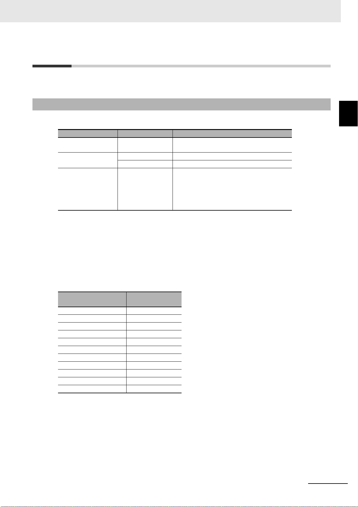
1 Features and System Configuration
1-5 Applicable Standards
This section describes applicable standards.
1-5-1 EU Directives
The 1S-series Servo Drives/Servomotors Advance Type comply with the following EU directives.
EU Directives Product Applicable standards
EMC Directive Servo Drives EN61800-3 second environment,
C3 Category
Low Voltage Directive Servo Drives EN61800-5-1
Servomotors EN 60034-1/-5
Machinery Directive Servo Drives EN ISO 13849-1 PLe/Cat.3
EN 61508 SIL3
EN 62061 SIL CL3
EN 61800-5-2 SIL3
(STO/SS1/SS2/SOS/SLS/SLP/SDI/SBC)
1-5 Applicable Standards
1
1-5-1 EU Directives
Note To conform to EMC Directives, install the Servo Drive and Servomotor under the conditions described in 4-3
Wiring Conforming to EMC Directives on page 4-32.
The Servo Drives and Servomotors comply with EN 61800-5-1 as long as the following installation
conditions (a) and (b) are met.
(a) Use the Servo Drive in pollution degree 2 or 1 environment as specified in IEC 60664-1.
Example: Installation inside an IP54 control panel.
(b) Be sure to connect a fuse or an equivalent that the fusing time is shorter, which complies with IEC
60269-1 CLASS gG, between the power supply and noise filter.
Select a fuse that satisfies the maximum current rating of the following table.
Servo Drive model
R88D-1SAN02H-ECT 16A
R88D-1SAN04H-ECT 16A
R88D-1SAN08H-ECT 16A
R88D-1SAN10H-ECT 16A
R88D-1SAN15H-ECT 40A
R88D-1SAN20H-ECT 40A
R88D-1SAN30H-ECT 40A
R88D-1SAN10F-ECT 20A
R88D-1SAN15F-ECT 20A
R88D-1SAN20F-ECT 20A
R88D-1SAN30F-ECT 20A
Maximum current
rating
1S-series with Built-in EtherCAT Communications and Safety Functionality User’s Manual (I621)
1 - 21
Page 72

1 Features and System Configuration
1-5-2 UL and cUL Standards
Standard Product Applicable standards File number
UL standards Servo Drives UL 61800-5-1 E179149
Servomotors UL 1004-1, UL 1004-6 E331224
*1
CSA standards
*1. IN CANADA, TRANSIENT SURGE SUPPRESSION SHALL BE INSTALLED ON THE LINE SIDE OF THIS
EQUIPMENT AND SHALL BE RATED 277 V (PHASE TO GROUND), SUITABLE FOR OVERVOLTAGE
CATEGORY III, AND SHALL PROVIDE PROTECTION FOR A RATED IMPULSE WITHSTAND VOLTAGE
PEAK OF 6 KV
Servo Drives CSA C22.2 No. 274 E179149
Servomotors CSA C22.2 No. 100 E331224
The Servo Drives and Servomotors comply with UL 61800-5-1 as long as the following installation conditions (a) and (b) are met.
(a) Use the Servo Drive in pollution degree 2 or 1 environment as specified in IEC 60664-1.
Example: Installation inside a control panel.
(b) Be sure to connect a fuse, which is a UL-listed product with LISTED, between the power supply and
noise filter.
Select the fuse from the following table as well as an equivalent, or the fuse that belongs to the following class: CC, CF, GF, G, J, R or T.
Use copper wiring with a temperature rating of 75°C or higher.
The 1S-series Servo Drives/Servomotors Advance Type conform to the following standards.
Servo Drive model CLASS
R88D-1SAN02H-ECT RK5 240 V 15 A
R88D-1SAN04H-ECT RK5 240 V 15 A
R88D-1SAN08H-ECT RK5 240 V 15 A
R88D-1SAN10H-ECT RK5 240 V 15 A
R88D-1SAN15H-ECT RK5 240 V 40 A
R88D-1SAN20H-ECT RK5 240 V 40 A
R88D-1SAN30H-ECT RK5 240 V 40 A
R88D-1SAN10F-ECT RK5 240 V 20 A
R88D-1SAN15F-ECT RK5 240 V 20 A
R88D-1SAN20F-ECT RK5 240 V 20 A
R88D-1SAN30F-ECT RK5 240 V 20 A
Vol tage
(Minimum)
Ampere
1 - 22
1S-series with Built-in EtherCAT Communications and Safety Functionality User’s Manual (I621)
Page 73

Precautions for Correct Use
1-5-3 Korean Radio Regulations (KC)
• Observe the following precaution if you use this product in Korea.
1 Features and System Configuration
1-5 Applicable Standards
Guide for Users
This equipment has been evaluated for conformity in a commercial environment.
When used in a residential environment, it may cause radio interference.
• The 1S-series Servo Drives Advance Type comply with the Korean Radio Regulations (KC).
• The 1S-series Servomotors Advance Type are exempt from the Korean Radio Regulations (KC).
1-5-4 SEMI F47
• The main power supply inputs can conform to the SEMI F47 standard for momentary power interruptions (voltage sag immunity) for no-load operation.
• This standard applies to semiconductor manufacturing equipment.
• This standard does not apply to the 24-VDC control power input. Use the power supply.
• Be sure to perform evaluation tests for SEMI F47 compliance in the entire machine and system.
1-5-5 Australian EMC Labeling Requirements (RCM)
• The 1S-series Servo Drives Advance Type comply with the Australian EMC Labeling Requirements
(RCM).
• The 1S-series Servomotors Advance Type comply with the Australian EMC Labeling Requirements
(RCM).
1
1-5-3 Korean Radio Regulations (KC)
1-5-6 EAC Requirements
• The 1S-series Servo Drives Advance Type comply with the EAC requirements.
• The 1S-series Servomotors Advance Type comply with the EAC requirements.
1S-series with Built-in EtherCAT Communications and Safety Functionality User’s Manual (I621)
1 - 23
Page 74
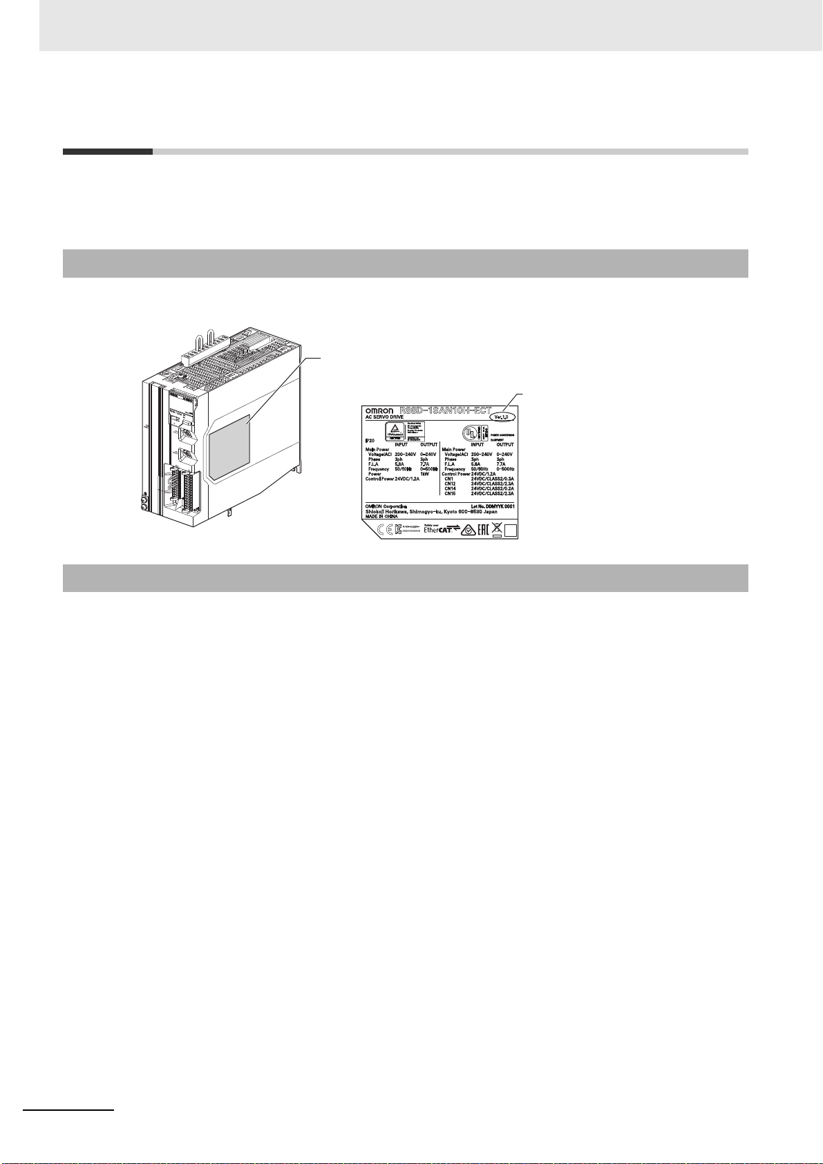
1 Features and System Configuration
1-6 Unit Versions
The 1S-series Servo Drive Advance Type uses unit versions.
Unit versions are used to manage differences in supported functions due to product upgrades, etc.
1-6-1 Confirmation Method
The unit version of 1S-series Servo Drive Advance Type is displayed at the location shown below.
Display location
Display on the product
Unit version
1-6-2 Unit Versions and Sysmac Studio Versions
Refer to A-7 Version Information on page A-239 for details on the relationship between the 1S-series
Servo Drive Advance Type and Sysmac Studio versions.
1 - 24
1S-series with Built-in EtherCAT Communications and Safety Functionality User’s Manual (I621)
Page 75

1 Features and System Configuration
STEP 1 System Design
STEP 1-1 Determining safety measures based on risk assessment
STEP 1-2 Selecting standard devices, Servo Drive, Servomotor, and safety devices
STEP 1-3 Designing interface between standard control and safety control
STEP 2 Software and hardware design for
standard control
STEP 2-1 Designing I/O and processing
STEP 2-2 Designing tasks
STEP 2-3 Designing user programs
STEP 4 Calculation and verification of safety
control responsivity
STEP 4-1 Calculating safety reaction time
and safety distance
STEP 3 Software and hardware design for
safety control
STEP 3-1 Determining wiring for communications,
power supply, and connection with external I/O devices
STEP 3-2 Designing I/O and processing
STEP 3-3 Designing safety programs
STEP 4-2 Verifying specification requirement satisfaction
STEP 5 Software setting and programming for
standard control
STEP 5-1 Creating project
STEP 5-2 Creating slave and unit configuration
STEP 6 Software setting and programming for
safety control
STEP 5-3 Controller settings
STEP 5-4 Programming
STEP 5-5 Offline debugging
STEP 6-1 Creating safety control system
configuration
STEP 6-4 Assigning device variables to I/O ports
STEP 6-5 Programming
STEP 6-6 Offline debugging
STEP 6-2 Checking/setting safety process
data communications
STEP 6-3 Assigning devices to safety
I/O terminal
STEP 7 Servo Drive setting, adjustment, and operation check
STEP 7-1 Installation and mounting
STEP 7-2 Wiring and connections
STEP 7-3 Device setting
STEP 7-4 Test run
STEP 7-5 Adjustment
1-7 Procedures to Start Operation
1-7 Procedures to Start Opera-
This section explains the procedures to operate a system that incorporates Servo Drives.
1-7-1 Overall Procedure
Use the following procedures to build a system that incorporates Servo Drives.
To use the Servo Drive safety function, you must build the standard control and safety control together.
tion
1
1-7-1 Overall Procedure
1S-series with Built-in EtherCAT Communications and Safety Functionality User’s Manual (I621)
1 - 25
Page 76

1 Features and System Configuration
STEP 8 Mounting and wiring
STEP 8-1 Mounting
STEP 8-2 Wiring
STEP 9 Standard control operation check
STEP 9-1 Placing Sysmac Studio online
and downloading project
STEP 9-2 Online Debugging
STEP 10 Safety control operation check
STEP 10-1 Transferring configuration information
STEP 10-2 Checking operation with actual machine
STEP 10-3 Conducting safety validation test
STEP 10-4 Setting security of unit
STEP 10-5 Executing safety validation
from Sysmac Studio
STEP 11 Operation and maintenance
STEP 11-1 Operation
STEP 11-2 Troubleshooting
STEP 11-3 Inspection and replacement
1 - 26
1S-series with Built-in EtherCAT Communications and Safety Functionality User’s Manual (I621)
Page 77

1-7-2 Procedure Details
As described previously, the procedures for the standard control and safety control are performed in
parallel.
This section explains the procedure details for using the Servo Drive safety function.
If you use an NJ/NX-series CPU Unit to perform the standard control, refer to NJ/NX-series CPU Unit
Software User's Manual (Cat. No. W501) together with this manual.
If you use an NX-series Safety Control Unit to perform the safety control, refer to NX-series Safety Con-
trol Unit User’s Manual (Cat. No. Z930) together with this manual.
STEP 1 System Design
Procedure Description Reference
STEP 1-1
Determining safety measures based on risk
assessment
1 Features and System Configuration
1-7 Procedures to Start Opera-
tion
1
1-7-2 Procedure Details
• Identify the source of danger and perform the risk
assessment (estimation and evaluation).
• Consider and determine the measures for risk minimization.
STEP 1-2
Selecting standard
device, Servo Drive, Servomotor, and safety
device
STEP 1-3
Designing interface
between standard control and safety control
STEP 2 Software and Hardware Design for Standard Control
Procedure Description Reference
STEP 2-1
Designing I/O and processing
STEP 2-2
Designing tasks
• Select the device that configures inputs, logics, and
outputs for standard control.
• Select the Servo Drive and Servomotor.
• Select the safety device used to configure inputs,
logics, and outputs for safety control.
Design the interface between the standard control and
safety control.
Design I/O and processing.
• External I/O devices and unit configuration
• Refresh periods for external devices
• Program contents
Design the tasks.
• Task configuration
• Relationship between tasks and programs
• Task periods
• Slave and Unit refresh times
• Exclusive control methods for variables between
tasks
Manuals for each unit
• Safety Control Unit
User's Manual
• Section 8, 8-1-2
NJ/NX-series CPU Unit
User’s Manuals
NJ/NX-series CPU Unit
User’s Manuals
STEP 2-3
Designing user programs
1S-series with Built-in EtherCAT Communications and Safety Functionality User’s Manual (I621)
• Design POUs (Program Organization Unit).
• Design variables.
NJ/NX-series CPU Unit
User’s Manuals
1 - 27
Page 78

1 Features and System Configuration
STEP 3 Software and Hardware Design for Safety Control
Procedure Description Reference
STEP 3-1
Determining wiring for
communications, power
supply, and connection
with external I/O devices
Determine wiring used for the communication network,
power supply, and safety I/O devices.
Safety Control Unit User's
Manual
STEP 3-2
Designing I/O and processing
Design the configuration of the safety I/O devices and
Safety I/O Unit.
• Safety I/O devices
• Safety Control Unit
User's Manual
• Section 8
• Program contents
STEP 3-3
Designing safety programs
Design POUs (Program Organization Unit).
• Programs
• Function blocks
• Safety Control Unit
User's Manual
• Section 8
STEP 4 Calculation and Verification of Safety Control Responsivity
Procedure Description Reference
STEP 4-1
Calculating safety reaction time and safety dis-
Calculate the safety reaction time and then determine
the safety distance.
• Safety Control Unit
User's Manual
• Section 8
tance
STEP 4-2
Verifying specification
Verify whether the specification requirements are satisfied. If not, reconsider the system design.
Safety Control Unit User's
Manual
requirement satisfaction
STEP 5 Software Design and Programming for Standard Control
Procedure Description Reference
STEP 5-1
Creating project
STEP 5-2
Creating slave and unit
configuration
• Create a new project in the Sysmac Studio.
• Insert a Controller.
• Create the slave configuration and Unit configuration
either offline or online.
• Include the safety PDOs (1610 hex and 1A10 hex) in
PDO mapping for the Servo Drive.
• Register the device variables in the variable table.
NJ/NX-series CPU Unit
User’s Manuals
• NJ/NX-series CPU Unit
User’s Manuals
• Section 8, 8-1
• Create the axes and set them as real axes or virtual
axes. Create axes groups to perform interpolated
axes control.
STEP 5-3
Controller settings
Set PLC Function Modules, Motion Control Function
Modules, etc. in the Sysmac Studio.
NJ/NX-series CPU Unit
User’s Manuals
1 - 28
1S-series with Built-in EtherCAT Communications and Safety Functionality User’s Manual (I621)
Page 79

1 Features and System Configuration
STEP 5 Software Design and Programming for Standard Control
Procedure Description Reference
• Register variables in the Sysmac Studio.
STEP 5-4
Programming
• Write the algorithms for the POUs (programs, func-
tion blocks, and functions) in the required languages.
• Make task settings.
1-7 Procedures to Start Opera-
NJ/NX-series CPU Unit
User’s Manuals
tion
STEP 5-5
Offline Debugging
Check the algorithms and task execution times on the
Simulator (virtual controller).
NJ/NX-series CPU Unit
User’s Manuals
1
1-7-2 Procedure Details
STEP 6 Software Design and Programming for Safety Control
Procedure Description Reference
STEP 6-1
Creating safety control
Arrange the Communications Coupler Unit, Safety
CPU Unit, and Safety I/O Unit in the Sysmac Studio.
Safety Control Unit User's
Manual
system configuration
• Safety Control Unit
User's Manual
• Section 8
STEP 6-2
Checking/setting Safety
Process Data Communications
• Select Safety Controller from the Controller Selection
Box in the Sysmac Studio.
• Check or change the settings of Safety Process Data
Communications.
• Make sure that the Servo Drive is displayed, and
then select the Active check box.
• Select safety functions for use of the assigned safety
PDOs (1610 hex and 1A10 hex).
• Set parameters of each safety function for use.
STEP 6-3
Assigning devices to
safety I/O terminal
In the parameter setting view for the Safety I/O Unit,
select the safety I/O devices connected to the safety
I/O terminal.
Safety Control Unit User's
Manual
STEP 6-4
Assigning device variables to I/O ports
STEP 6-5
Programming
STEP 6-6
Offline Debugging
Register the device variables in the variable table.
(Variable names are user defined or automatically cre-
Safety Control Unit User's
Manual
ated.)
• Register the variables used by more than one POU
in the global variable table with the Sysmac Studio.
• Register the variables in the local variable table for
• Safety Control Unit
User's Manual
• Section 8
each program.
• Register the variables in the local variable table for
each function block.
• Write the algorithms for the POUs (programs and
function blocks) in FBD language.
Execute program debugging with the Simulator. Safety Control Unit User's
Manual
1S-series with Built-in EtherCAT Communications and Safety Functionality User’s Manual (I621)
1 - 29
Page 80

1 Features and System Configuration
STEP 7 Servo Drive Setting, Adjustment, and Operation Check
Procedure Description Reference
STEP 7-1
Installation and mounting
STEP 7-2
Wiring and connections
Install the Servomotor and Servo Drive according to the
installation conditions. Do not connect the Servomotor
to mechanical systems before checking the operation
without any load.
Connect the Servomotor and Servo Drive to the power
supply and peripheral equipment.
Satisfy specified installation and wiring conditions, particularly for models that conforms to the EU Directives.
Section 4, 4-1
Section 4, 4-2
STEP 7-3
Device setting
Set the objects related to the functions required for
application conditions.
Section 9
• First, check motor operation without any load. Then
turn the power supply OFF and connect the Servo-
STEP 7-4
Test run
motor to mechanical systems.
• Use the STO function via safety input signals if you
Section 10, 10-3
need the STO function while you perform the test run
or adjustment using the Servo Drive with no load.
STEP 7-5
Adjustment
Manually adjust the gain if necessary.
Section 11
STEP 8 Mounting and Wiring
Procedure Description Reference
STEP 8-1
Install each unit according to the installation conditions. Manuals for each unit
Mounting
STEP 8-2
Connect the network cables and wire the I/O. Manuals for each unit
Wiring
1 - 30
STEP 9 Standard Control Operation Check
Procedure Description Reference
STEP 9-1
Placing Sysmac Studio
online and downloading
• Turn ON the power supply to the Controller and place
the Sysmac Studio online.
• Download the project.
project
• Check the wiring by using forced refreshing of real
I/O from the I/O Map or Watch Tab Page.
• For motion control, use the MC Test Run operations
STEP 9-2
Online Debugging
in PROGRAM mode to check the wiring. Then check
the motor rotation directions for jogging, travel distances for relative positioning (e.g., for electronic
gear settings), and homing operation.
• Change the Controller to RUN mode and check the
operation of the user program.
1S-series with Built-in EtherCAT Communications and Safety Functionality User’s Manual (I621)
NJ/NX-series CPU Unit
User’s Manuals
NJ/NX-series CPU Unit
User’s Manuals
Page 81

1 Features and System Configuration
1-7 Procedures to Start Opera-
STEP 10 Safety Control Operation Check
Procedure Description Reference
• NJ/NX-series CPU Unit
User’s Manuals
• Safety Control Unit
User's Manual
tion
1
1-7-2 Procedure Details
STEP 10-1
Transferring configuration information
• Connect the computer (Sysmac Studio) to the
NJ/NX-series CPU Unit.
• Download the project data to the CPU Unit.
• In the Safety CPU Unit Setup and Programming
View, change the mode of the Safety CPU Unit to
DEBUG mode. By doing this, the safety application
data is transferred to the Safety CPU Unit and the
test run for debugging is enabled.
STEP 10-2
Checking operation with
actual machine
STEP 10-3
Conducting safety vali-
Perform the wiring check and program operation check
to confirm that the Safety Control Unit operates as
intended.
Conduct the test to check whether all safety functions
operate as designed.
Safety Control Unit User's
Manual
Safety Control Unit User's
Manual
dation test
STEP 10-4
Setting security of unit
STEP 10-5
Executing safety validation from Sysmac Studio
Set the safety password. Safety Control Unit User's
Manual
If the safety validation test is completed successfully,
then execute the safety validation command from Sys-
Safety Control Unit User's
Manual
mac Studio.
By doing this, the safety application data is transferred
to the non-volatile memory in the Safety CPU Unit, and
the operation-ready status is established.
STEP 11 Operation and Maintenance
Procedure Description Reference
Start actual operation.
STEP 11-1
Operation
Start actual operation after checking the present device
position and the position displayed on the Servo Drives
---
are appropriate.
STEP 11-2
Troubleshooting
STEP11-3
Inspection and replacement
1S-series with Built-in EtherCAT Communications and Safety Functionality User’s Manual (I621)
In case of an error, use the troubleshooting function of
the Sysmac Studio to check the error and identify its
cause, and then remove the cause of the error.
Perform periodic maintenance.
If any defect is found during inspection, replace the
device.
• Section 9
• Manuals for each unit
• Section 10
• Manuals for each unit
1 - 31
Page 82

1 Features and System Configuration
1 - 32
1S-series with Built-in EtherCAT Communications and Safety Functionality User’s Manual (I621)
Page 83

Models and External Dimensions
This section explains the models of Servo Drives, Servomotors, Decelerators, and
peripheral devices, and provides the external dimensions and mounting dimensions.
2-1 Servo System Configuration . . . . . . . . . . . . . . . . . . . . . . . . . . . . . . . . . . . . . 2-2
2-2 How to Read Model Numbers . . . . . . . . . . . . . . . . . . . . . . . . . . . . . . . . . . . . 2-4
2-2-1 Servo Drive . . . . . . . . . . . . . . . . . . . . . . . . . . . . . . . . . . . . . . . . . . . . . . . . . . . 2-4
2-2-2 Servomotor . . . . . . . . . . . . . . . . . . . . . . . . . . . . . . . . . . . . . . . . . . . . . . . . . . . 2-5
2-2-3 Integrated Cable . . . . . . . . . . . . . . . . . . . . . . . . . . . . . . . . . . . . . . . . . . . . . . . 2-6
2-2-4 Decelerator . . . . . . . . . . . . . . . . . . . . . . . . . . . . . . . . . . . . . . . . . . . . . . . . . . . 2-7
2-3 Model Tables . . . . . . . . . . . . . . . . . . . . . . . . . . . . . . . . . . . . . . . . . . . . . . . . . . 2-9
2-3-1 Servo Drive Model Table . . . . . . . . . . . . . . . . . . . . . . . . . . . . . . . . . . . . . . . . 2-9
2-3-2 Servomotor Model Tables . . . . . . . . . . . . . . . . . . . . . . . . . . . . . . . . . . . . . . . 2-10
2-3-3 Servo Drive and Servomotor Combination Tables . . . . . . . . . . . . . . . . . . . . 2-12
2-3-4 Decelerator Model Tables . . . . . . . . . . . . . . . . . . . . . . . . . . . . . . . . . . . . . . . 2-13
2-3-5 Servomotor and Decelerator Combination Tables . . . . . . . . . . . . . . . . . . . . 2-15
2-3-6 Table of Integrated Cables, Connectors, and Shield Clamps . . . . . . . . . . . . 2-16
2-3-7 External Regeneration Resistor and External Regeneration Resistance Unit
Model Tables . . . . . . . . . . . . . . . . . . . . . . . . . . . . . . . . . . . . . . . . . . . . . . . . 2-19
2-3-8 Reactor Model Table . . . . . . . . . . . . . . . . . . . . . . . . . . . . . . . . . . . . . . . . . . . 2-20
2-4 External and Mounting Dimensions . . . . . . . . . . . . . . . . . . . . . . . . . . . . . . 2-21
2-4-1 Servo Drive Dimensions . . . . . . . . . . . . . . . . . . . . . . . . . . . . . . . . . . . . . . . . 2-21
2-4-2 Servomotor Dimensions . . . . . . . . . . . . . . . . . . . . . . . . . . . . . . . . . . . . . . . . 2-23
2-4-3 Cable Outlet Direction of Integrated Connector . . . . . . . . . . . . . . . . . . . . . . 2-43
2-4-4 Cable Wiring Dimension for a Case of Servomotor Installing . . . . . . . . . . . . 2-44
2-4-5 Decelerator Dimensions . . . . . . . . . . . . . . . . . . . . . . . . . . . . . . . . . . . . . . . . 2-46
2-4-6 Dimensions of External Regeneration Resistors and External Regeneration
Resistance Units . . . . . . . . . . . . . . . . . . . . . . . . . . . . . . . . . . . . . . . . . . . . . . 2-55
2-4-7 Reactor Dimensions . . . . . . . . . . . . . . . . . . . . . . . . . . . . . . . . . . . . . . . . . . . 2-56
2
1S-series with Built-in EtherCAT Communications and Safety Functionality User’s Manual (I621)
2 - 1
Page 84

2 Models and External Dimensions
ID211
0
1
3
2
4
5
7
6
8
9
11
10
12
13
14
15
DC24V
7mA
COM
MACH
No
.
AD042
RUN
ER
C
ERH
B1A1
x10
1
x10
0
0
9
8
7
6
5
4
3
2
1
0
9
8
7
6
5
4
3
2
1
0 1 2 3 4 567
8
9
1011 12 1314 15
NJ/NX-series CPU Unit
(with EtherCAT port)
Controller
Machine Automation Controller
NJ/NX-series
CJ-series CPU Unit
+ Position Control Unit (with EtherCAT Interface)
Programmable Controller
CJ-CPU
Position Control Unit (NC)
CJ1W-NC8
Support Software
● Automation Software
Sysmac Studio
Support Software
● FA Integrated Tool Package
CX-One
*1
(CX-Programmer
included)
NY-series CPU Unit
(with EtherCAT port)
IPC Machine Controller
NY-series
2-1 Servo System Configuration
This section shows the Servo system configuration that consists of Controllers, Servo Drives, Servomotors, Decelerators, and other devices.
*1. You cannot use the CX-One to make the settings of 1S-series Servo Drives Advance Type. Obtain the Sysmac Studio.
2 - 2
1S-series with Built-in EtherCAT Communications and Safety Functionality User’s Manual (I621)
Page 85

2 Models and External Dimensions
2-1 Servo System Configuration
USB
communications
EtherCAT
communications
Servo Drive
Power signal
Integrated cable
· Without brake wire
R88A-CX1SF
· With brake wire
R88A-CX1BF
· Extension cable
R88A-CX1EBF
Servomotor
2
● 1S-series Servo Drive
Advance Type
R88D-1SAN-ECT
200 VAC
400 VAC
Feedback signal
● 1S-series Servomotor
Advance Type
R88M-1AL/1AM
3,000 r/min
1,500 r/min
Decelerator
●
Backlash: 3 Arcminutes max.
R88G-HPG
●
Backlash: 15 Arcminutes max.
R88G-VRXF
1S-series with Built-in EtherCAT Communications and Safety Functionality User’s Manual (I621)
2 - 3
Page 86

2 Models and External Dimensions
Communications type
Applicable Servomotor rated output
Power supply voltage
1S-series
Servo Drive
ECT: EtherCAT communications type
AN: Advance/Communications type
Servo Drive Type
R88D-1SAN02H-ECT
02: 200 W
04: 400 W
08: 750 W
10: 1 kW
15: 1.5 kW
20: 2 kW
30: 3 kW
H: 200 VAC
F: 400 VAC
2-2 How to Read Model Numbers
This section describes how to read and understand the model numbers of Servo Drives, Servomotors,
Integrated Cables, and Decelerators.
2-2-1 Servo Drive
The Servo Drive model number shows the Servo Drive type, applicable Servomotor, power supply voltage, etc.
2 - 4
1S-series with Built-in EtherCAT Communications and Safety Functionality User’s Manual (I621)
Page 87

2-2-2 Servomotor
R88M-1AM20030T-BOS2
200: 200 W
400: 400 W
750: 750 W
1K0: 1 kW
1K5: 1.5 kW
2K0: 2 kW
2K6: 2.6 kW
2K7: 2.7 kW
3K0: 3 kW
15: 1,500 r/min
30: 3,000 r/min
AL: Advance/Low-inertia type
AM: Advance/Middle-inertia type
T: 200 VAC absolute encoder
C: 400 VAC absolute encoder
Brake
None: Without brake
B: With 24-VDC brake
Oil seal
None: Without oil seal
O: With oil seal
Key and tap
None: Straight shaft
S2: With key and tap
Options
Servo Drive main power supply voltage and encoder type
Rated output
Rated rotation speed
Servomotor type
1S-series Servomotor
The Servomotor model number tells the Servomotor type, rated output, rated rotation speed, voltage,
etc.
2 Models and External Dimensions
2-2 How to Read Model Numbers
2
2-2-2 Servomotor
Combinations of Options
Straight shaft With key and tap Straight shaft With key and tap
Without
brake
With brake -B -BS2 -BO -BOS2
None -S2 -O -OS2
Without oil seal With oil seal
1S-series with Built-in EtherCAT Communications and Safety Functionality User’s Manual (I621)
2 - 5
Page 88

2 Models and External Dimensions
R88A-CX1A003BF
A: 200 VAC 3,000-r/min Servomotor 200 W, 400 W, 750 W
B: 200 VAC 3,000-r/min Servomotor 1 kW
C: 200 VAC 3,000-r/min Servomotor 1.5 kW
1,500-r/min Servomotor 1.5 kW
400 VAC 3,000-r/min Servomotor 750 kW, 1 kW, 1.5 kW, 2 kW, 3 kW
1,500-r/min Servomotor 1.5 kW, 3 kW
D: 200 VAC 3,000-r/min Servomotor 2 kW, 2.6 kW
1,500-r/min Servomotor 2.7 kW
003: 3 m
005: 5 m
010: 10 m
015: 15 m
020: 20 m
E10: 10 m (Extension cable)
E20: 20 m (Extension cable)
CX1: Integrated Cable
Peripheral for the 1S-series
Cable length
Applicable Servomotor type
Peripheral type
Connector type
Application
S: Without brake wire
B: With brake wire
F: Flexible cable
2-2-3 Integrated Cable
The cable model number tells the cable type, cable length, connector type, etc.
2 - 6
1S-series with Built-in EtherCAT Communications and Safety Functionality User’s Manual (I621)
Page 89

2-2-4 Decelerator
R88G-HPG32A112K0SBJ
05: 1/5
11: 1 /11
20: 1/20
21: 1/21
25: 1/25
33: 1/33
45: 1/45
200: 200 W
400: 400 W
600: 600 W
750: 750 W
900: 900 W
1K5: 1.5 kW
2K0: 2 kW
3K0: 3 kW
5K0: 5 kW
14A: 60×60
20A: 90×90
32A: 120×120
50A: 170×170
65A: 230×230
Decelerator for Servomotor
Applicable Servomotor rated output
*1
Backlash: 3 Arcminutes max.
Reduction ratio
Flange size number
Servomotor type
*1
*1. This is a standard model number of servo motor; this model number structure can be applied to other motors.
Confirm decelerator and servomotor combination table when you select a Servomotor.
Backlash
Options
None: 3,000-r/min Servomotors
S: 2,000-r/min Servomotors
T: 1,000-r/min Servomotors
B: Backlash: 3 Arcminutes max.
None: Straight shaft
J: With key and tap
The Decelerator model number tells the Decelerator series, flange size number, reduction ratio, backlash, etc.
Backlash: 3 Arcminutes Max.
2 Models and External Dimensions
2-2 How to Read Model Numbers
2
2-2-4 Decelerator
1S-series with Built-in EtherCAT Communications and Safety Functionality User’s Manual (I621)
2 - 7
Page 90

2 Models and External Dimensions
200: 200 W
400: 400 W
750: 750 W
05: 1/5
09: 1/9
15: 1/15
25: 1/25
B: 52×52
C: 78×78
D: 98×98
R88G-VRXF05B200CJ
Options
Decelerator for Servomotor
Applicable Servomotor rated output
Backlash: 15 Arcminutes Max.
Reduction ratio
Flange size number
Backlash
C: Backlash: 15 Arcminutes max.
J: With key and tap
Backlash: 15 Arcminutes Max.
2 - 8
1S-series with Built-in EtherCAT Communications and Safety Functionality User’s Manual (I621)
Page 91

2-3 Model Tables
2 Models and External Dimensions
This section lists the models of Servo Drives, Servomotors, Decelerators, cables, connectors, peripheral devices, etc. in the tables.
2-3-1 Servo Drive Model Table
The following table lists the Servo Drive models.
Specifications Model Reference
Single-phase/3-phase
200 VAC
3-phase 200 VAC 1 kW R88D-1SAN10H-ECT P. 2-21
3-phase 400 VAC 1 kW R88D-1SAN10F-ECT
200 W R88D-1SAN02H-ECT P. 2-21
400 W R88D-1SAN04H-ECT
750 W R88D-1SAN08H-ECT
1.5 kW R88D-1SAN15H-ECT P. 2-22
2 kW R88D-1SAN20H-ECT P. 2-22
3 kW R88D-1SAN30H-ECT
1.5 kW R88D-1SAN15F-ECT
2 kW R88D-1SAN20F-ECT
3 kW R88D-1SAN30F-ECT
2-3 Model Tables
2
2-3-1 Servo Drive Model Table
1S-series with Built-in EtherCAT Communications and Safety Functionality User’s Manual (I621)
2 - 9
Page 92

2 Models and External Dimensions
2-3-2 Servomotor Model Tables
3,000-r/min Servomotors
Specifications
Without brake
200 VAC 200 W R88M-
400 W R88M-
750 W R88M-
1 kW R88M-
1.5 kW R88M-
2 kW R88M-
2.6 kW R88M-
400 VAC 750 W R88M-
1 kW R88M-
1.5 kW R88M-
2 kW R88M-
3 kW R88M-
The following tables list the Servomotor models by the rated motor speed.
Model
Without oil seal With oil seal
Straight shaft With key and tap Straight shaft With key and tap
1AM20030T
1AM40030T
1AM75030T
1AL1K030T
1AL1K530T
1AL2K030T
1AL2K630T
1AL75030C
1AL1K030C
1AL1K530C
1AL2K030C
1AL3K030C
R88M1AM20030T-S2
R88M1AM40030T-S2
R88M1AM75030T-S2
R88M1AL1K030T-S2
R88M1AL1K530T-S2
R88M1AL2K030T-S2
R88M1AL2K630T-S2
R88M1AL75030C-S2
R88M1AL1K030C-S2
R88M1AL1K530C-S2
R88M1AL2K030C-S2
R88M-
3K030C-S2
1AL
R88M1AM20030T-O
R88M1AM40030T-O
R88M1AM75030T-O
R88M1AL1K030T-O
R88M1AL1K530T-O
R88M1AL2K030T-O
R88M1AL2K630T-O
R88M1AL75030C-O
R88M1AL1K030C-O
R88M1AL1K530C-O
R88M1AL2K030C-O
R88M1AL3K030C-O
R88M1AM20030T-OS2
R88M1AM40030T-OS2
R88M1AM75030T-OS2
R88M1AL1K030T-OS2
R88M1AL1K530T-OS2
R88M1AL2K030T-OS2
R88M1AL2K630T-OS2
R88M1AL75030C-OS2
R88M1AL1K030C-OS2
R88M1AL1K530C-OS2
R88M1AL2K030C-OS2
R88M1AL3K030C-OS2
Refer-
ence
P. 2 -2 3
P. 2 -2 3
P. 2 -2 7
P. 2 -2 9
P. 2 -2 9
P. 2 -2 9
P. 2 -3 1
P. 2 -3 3
P. 2 -3 3
P. 2 -3 3
P. 2 -3 3
P. 2 -3 7
2 - 10
1S-series with Built-in EtherCAT Communications and Safety Functionality User’s Manual (I621)
Page 93

2 Models and External Dimensions
Specifications
With brake
200 VAC 200 W R88M-
400 W R88M-
750 W R88M-
1 kW R88M-
1.5 kW R88M-
2 kW R88M-
2.6 kW R88M-
400 VAC 750 W R88M-
1 kW R88M-
1.5 kW R88M-
2 kW R88M-
3 kW R88M-
Model
Without oil seal With oil seal
Straight shaft With key and tap Straight shaft With key and tap
1AM20030T-B
1AM40030T-B
1AM75030T-B
1AL1K030T-B
1AL1K530T-B
1AL2K030T-B
1AL2K630T-B
1AL75030C-B
1AL1K030C-B
1AL1K530C-B
1AL2K030C-B
1AL3K030C-B
R88M1AM20030T-BS2
R88M1AM40030T-BS2
R88M1AM75030T-BS2
R88M1AL1K030T-BS2
R88M1AL1K530T-BS2
R88M1AL2K030T-BS2
R88M1AL2K630T-BS2
R88M1AL75030C-BS2
R88M1AL1K030C-BS2
R88M1AL1K530C-BS2
R88M1AL2K030C-BS2
R88M-
K030C-BS2
1AL3
R88M1AM20030T-BO
R88M1AM40030T-BO
R88M1AM75030T-BO
R88M1AL1K030T-BO
R88M1AL1K530T-BO
R88M1AL2K030T-BO
R88M1AL2K630T-BO
R88M1AL75030C-BO
R88M1AL1K030C-BO
R88M1AL1K530C-BO
R88M1AL2K030C-BO
R88M1AL3K030C-BO
R88M1AM20030T-BOS2
R88M1AM40030T-BOS2
R88M1AM75030T-BOS2
R88M1AL1K030T-BOS2
R88M1AL1K530T-BOS2
R88M1AL2K030T-BOS2
R88M1AL2K630T-BOS2
R88M1AL75030C-BOS2
R88M1AL1K030C-BOS2
R88M1AL1K530C-BOS2
R88M1AL2K030C-BOS2
R88M1AL3K030C-BOS2
Refer-
ence
P. 2 - 25
2-3 Model Tables
P. 2 - 25
P. 2 - 28
P. 2 - 30
P. 2 - 30
2
P. 2 - 30
2-3-2 Servomotor Model Tables
P. 2 - 32
P. 2 - 35
P. 2 - 35
P. 2 - 35
P. 2 - 35
P. 2 - 38
1,500-r/min Servomotors
Specifications
Without brake
200 VAC 1.5 kW R88M-
2.7 kW R88M-
400 VAC 1.5 kW R88M-
3 kW R88M-
With brake
200 VAC 1.5 kW R88M-
2.7 kW R88M-
400 VAC 1.5 kW R88M-
3 kW R88M-
Model
Without oil seal With oil seal
Straight shaft With key and tap Straight shaft With key and tap
1AM1K515T
1AM2K715T
1AM1K515C
1AM3K015C
1AM1K515T-B
1AM2K715T-B
1AM1K515C-B
1AM3K015C-B
R88M1AM1K515T-S2
R88M1AM2K715T-S2
R88M1AM1K515C-S2
R88M1AM3K015C-S2
R88M1AM1K515T-BS2
R88M1AM2K715T-BS2
R88M1AM1K515C-BS2
R88M1AM3K015C-BS2
R88M1AM1K515T-O
R88M1AM2K715T-O
R88M1AM1K515C-O
R88M1AM3K015C-O
R88M1AM1K515T-BO
R88M1AM2K715T-BO
R88M1AM1K515C-BO
R88M1AM3K015C-BO
R88M1AM1K515T-OS2
R88M1AM2K715T-OS2
R88M1AM1K515C-OS2
R88M1AM3K015C-OS2
R88M1AM1K515T-BOS2
R88M1AM2K715T-BOS2
R88M1AM1K515C-BOS2
R88M1AM3K015C-BOS2
Refer-
ence
P. 2-39
P. 2-41
P. 2-39
P. 2-41
P. 2-40
P. 2-42
P. 2-40
P. 2-42
1S-series with Built-in EtherCAT Communications and Safety Functionality User’s Manual (I621)
2 - 11
Page 94

2 Models and External Dimensions
2-3-3 Servo Drive and Servomotor Combination Tables
The following tables show the possible combinations of 1S-series Servo Drives Advance Type and Servomotors. The Servomotors and Servo Drives can only be used in the listed combinations. “” at the
end of the motor model number is for options, such as the shaft type and brake.
3,000-r/min Servomotors and Servo Drives
Main circuit power
supply voltage
Single-phase/3-phase
200 VAC
3-phase 200 VAC 1 kW R88M-1AL1K030T- R88D-1SAN10H-ECT
3-phase 400 VAC 750 W R88M-1AL75030C- R88D-1SAN10F-ECT
Servomotor
rated output
200 W R88M-1AM20030T- R88D-1SAN02H-ECT
400 W R88M-1AM40030T- R88D-1SAN04H-ECT
750 W R88M-1AM75030T- R88D-1SAN08H-ECT
1.5 kW R88M-1AL1K530T- R88D-1SAN15H-ECT
2 kW R88M-1AL2K030T- R88D-1SAN20H-ECT
2.6 kW R88M-1AL2K630T- R88D-1SAN30H-ECT
1 kW R88M-1AL1K030C- R88D-1SAN10F-ECT
1.5 kW R88M-1AL1K530C- R88D-1SAN15F-ECT
2 kW R88M-1AL2K030C- R88D-1SAN20F-ECT
3 kW R88M-1AL3K030C- R88D-1SAN30F-ECT
Servomotor Servo Drive
1,500-r/min Servomotors and Servo Drives
Main circuit power
supply voltage
Single-phase/3-phase
200 VAC
3-phase 200 VAC 2.7 kW R88M-1AM2K715T- R88D-1SAN30H-ECT
3-phase 400 VAC 1.5 kW R88M-1AM1K515C- R88D-1SAN15F-ECT
Servomotor
rated output
1.5 kW R88M-1AM1K515T- R88D-1SAN15H-ECT
3 kW R88M-1AM3K015C- R88D-1SAN30F-ECT
Servomotor Servo Drive
2 - 12
1S-series with Built-in EtherCAT Communications and Safety Functionality User’s Manual (I621)
Page 95
2-3-4 Decelerator Model Tables
The following tables list the Decelerator models for 1S-series Servomotors Advance Type.
The standard shaft type is a straight shaft. A model with a key and tap is indicated with “J” at of the
Decelerator model number in the following table. Select an appropriate model based on the Servomotor
rated output.
Backlash: 3 Arcminutes Max.
2 Models and External Dimensions
2-3 Model Tables
For 3,000-r/min Servomotors
Specifications
Servomotor
rated output
200 W 1/5 R88G-HPG14A05200B P. 2 - 46
400 W 1/5 R88G-HPG14A05400B P. 2 - 49
750 W (200 V) 1/5 R88G-HPG20A05750B
750 W (400 V) 1/5 R88G-HPG32A052K0B
1 kW 1/5 R88G-HPG32A052K0B P. 2- 4 9
1.5 kW 1/5 R88G-HPG32A052K0B
2 kW 1/5 R88G-HPG32A052K0B
2.6 kW (200 V)
3 kW (400 V)
Reduction
ratio
1/11 R88G-HPG14A11200B
1/21 R88G-HPG20A21200B
1/33 R88G-HPG20A33200B
1/45 R88G-HPG20A45200B
1/11 R88G-HPG20A11400B
1/21 R88G-HPG20A21400B
1/33 R88G-HPG32A33400B
1/45 R88G-HPG32A45400B
1/11 R88G-HPG20A11750B
1/21 R88G-HPG32A21750B
1/33 R88G-HPG32A33750B
1/45 R88G-HPG32A45750B
1/11 R88G-HPG32A112K0B
1/21 R88G-HPG32A211K5B
1/33 R88G-HPG32A33600SB
1/11 R88G-HPG32A112K0B
1/21 R88G-HPG32A211K5B
1/11 R88G-HPG32A112K0B
1/21 R88G-HPG32A211K5B
1/11 R88G-HPG32A112K0B
1/5 R88G-HPG32A053K0B
Model Reference
2
2-3-4 Decelerator Model Tables
1S-series with Built-in EtherCAT Communications and Safety Functionality User’s Manual (I621)
2 - 13
Page 96

2 Models and External Dimensions
For 1,500-r/min Servomotors
Specifications
Servomotor
rated output
Reduction
ratio
1.5 kW 1/5 R88G-HPG32A053K0B P. 2-51
1/11 R88G-HPG32A112K0SB
1/21 R88G-HPG50A21900TB
1/33 R88G-HPG50A33900TB
2.7 kW (200 V)
3 kW (400 V)
1/5 R88G-HPG50A055K0SB
1/11 R88G-HPG50A115K0SB
1/20 R88G-HPG65A205K0SB
1/25 R88G-HPG65A255K0SB
Backlash: 15 Arcminutes Max.
For 3,000-r/min Servomotors
Specifications
Servomotor
rated output
200 W 1/5 R88G-VRXF05B200CJ P. 2-53
400 W 1/5 R88G-VRXF05C400CJ
750 W (200 V) 1/5 R88G-VRXF05C750CJ
Reduction
ratio
1/9 R88G-VRXF09C200CJ
1/15 R88G-VRXF15C200CJ
1/25 R88G-VRXF25C200CJ
1/9 R88G-VRXF09C400CJ
1/15 R88G-VRXF15C400CJ
1/25 R88G-VRXF25C400CJ
1/9 R88G-VRXF09D750CJ
1/15 R88G-VRXF15D750CJ
1/25 R88G-VRXF25D750CJ
Model Reference
Model Reference
2 - 14
1S-series with Built-in EtherCAT Communications and Safety Functionality User’s Manual (I621)
Page 97

2 Models and External Dimensions
2-3-5 Servomotor and Decelerator Combination Tables
The following tables show the possible combinations of 1S-series Servomotors Advance Type and
Decelerators. You cannot use a Servomotor with a key and tap (model numbers with -S2 at the end) in
combination with a Decelerator.
Backlash: 3 Arcminutes Max.
Servomotor 3,000 r/min and Decelerator Combination Table
Servomotor
models
R88M1AM20030
R88M1AM40030
R88M1AM75030
(200 VAC)
R88M1AL75030
(400 VAC)
R88M1AL1K030
R88M1AL1K530
R88M1AL2K030
R88M1AL2K630
R88M1AL3K030
1/5 1/11 1/21 1/33 1/45
R88G-HPG
14A05200B
R88G-HPG
14A05400B
R88G-HPG
20A05750B
R88G-HPG
32A052K0B
R88G-HPG
32A053K0B
R88G-HPG
14A11200B
R88G-HPG
20A11400B
R88G-HPG
20A11750B
R88G-HPG
32A112K0B
---
Reduction ratio
R88G-HPG
20A21200B
R88G-HPG
20A21400B
R88G-HPG
32A21750B
R88G-HPG
32A211K5B
---
R88G-HPG
20A33200B
R88G-HPG
32A33400B
R88G-HPG
32A33750B
R88G-HPG
32A33600SB
2-3 Model Tables
2
R88G-HPG
20A45200B
R88G-HPG
32A45400B
R88G-HPG
32A45750B
---
---
2-3-5 Servomotor and Decelerator Combination Tables
Servomotor 1,500 r/min and Decelerator Combination Table
Servomotor
models
R88M1AM1K515
R88M1AM2K715
R88M1AM3K015
1/5 1/11 1/20 1/21 1/25 1/33
R88G-HPG
32A053K0B
R88G-HPG
50A055K0SB
R88G-HPG
32A112K0SB
R88G-HPG
50A115K0SB
R88G-HPG
65A205K0SB
Reduction ratio
---
R88G-HPG
50A21900TB
---
---
R88G-HPG
65A255K0SB
R88G-HPG
50A33900TB
---
Backlash: 15 Arcminutes Max.
Servomotor 3,000 r/min and Decelerator Combination Table
Servomotor
models
R88M-1AM20030 R88G-VRXF05B200CJ R88G-VRXF09C200CJ R88G-VRXF15C200CJ R88G-VRXF25C200CJ
R88M-1AM40030 R88G-VRXF05C400CJ R88G-VRXF09C400CJ R88G-VRXF15C400CJ R88G-VRXF25C400CJ
R88M-1AM75030
(AC200V)
R88G-VRXF05C750CJ R88G-VRXF09D750CJ R88G-VRXF15D750CJ R88G-VRXF25D750CJ
1/5 1/9 1/15 1/25
Reduction ratio
1S-series with Built-in EtherCAT Communications and Safety Functionality User’s Manual (I621)
2 - 15
Page 98

2 Models and External Dimensions
2-3-6 Table of Integrated Cables, Connectors, and Shield Clamps
Types of integrated cables, connectors, and shield clamps are listed below.
Integrated Cable
Applicable Servomotors
200 V 3,000-r/min Servomotors of
200 W, 400 W, 750 W
200 V 3,000-r/min Servomotors of
1 kW
200 V
400 V
200 V 3,000-r/min Servomotors of
200 V
3,000-r/min Servomotors of
1.5 kW
1,500-r/min Servomotors of
1.5 kW
400 V
3,000-r/min Servomotors of
750 W, 1 kW, 1.5 kW, 2 kW, 3 kW
1,500-r/min Servomotors of
1.5 kW, 3kW
2 kW, 2.6 kW
1,500-r/min Servomotors of
2.7 kW
Model
Without brake wire With brake wire
3 m R88A-CX1A003SF R88A-CX1A003BF
5 m R88A-CX1A005SF R88A-CX1A005BF
10 m R88A-CX1A010SF R88A-CX1A010BF
15 m R88A-CX1A015SF R88A-CX1A015BF
20 m R88A-CX1A020SF R88A-CX1A020BF
3 m R88A-CX1B003SF R88A-CX1B003BF
5 m R88A-CX1B005SF R88A-CX1B005BF
10 m R88A-CX1B010SF R88A-CX1B010BF
15 m R88A-CX1B015SF R88A-CX1B015BF
20 m R88A-CX1B020SF R88A-CX1B020BF
3 m R88A-CX1C003SF R88A-CX1C003BF
5 m R88A-CX1C005SF R88A-CX1C005BF
10 m R88A-CX1C010SF R88A-CX1C010BF
15 m R88A-CX1C015SF R88A-CX1C015BF
20 m R88A-CX1C020SF R88A-CX1C020BF
3 m R88A-CX1D003SF R88A-CX1D003BF
5 m R88A-CX1D005SF R88A-CX1D005BF
10 m R88A-CX1D010SF R88A-CX1D010BF
15 m R88A-CX1D015SF R88A-CX1D015BF
20 m R88A-CX1D020SF R88A-CX1D020BF
2 - 16
Extension Cable
Use the following extension cables regardless of whether or not a cable has a brake. Use
R88A-CX1BEBF when you use an extension cable for R88A-CX1C.
Applicable Servomotors Model
200 V 3,000-r/min Servomotors of
200 W, 400 W, 750 W
200 V
400 V
200 V
3,000-r/min Servomotors of
1 kW, 1.5 kW
1,500-r/min Servomotors of
1.5 kW
400 V
3,000-r/min Servomotors of
750 W, 1 kW, 1.5 kW, 2 kW, 3 kW
1,500-r/min Servomotors of
1.5 kW, 3 kW
1S-series with Built-in EtherCAT Communications and Safety Functionality User’s Manual (I621)
10 m R88A-CX1AE10BF
20 m R88A-CX1AE20BF
10 m R88A-CX1BE10BF
20 m R88A-CX1BE20BF
Page 99

2 Models and External Dimensions
Applicable Servomotors Model
200 V 3,000-r/min Servomotors of
2 kW, 2.6 kW
10 m R88A-CX1DE10BF
20 m R88A-CX1DE20BF
1,500-r/min Servomotors of
2.7 kW
2-3 Model Tables
Peripheral Connector
Servo Drive Side Connector
Name and application Model
Main circuit connector (CNA)
*1
R88A-CN102P
*4
For R88D-1SAN02H-ECT/ -1SAN04H-ECT/ -1SAN08H-ECT/ -1SAN10H-ECT
Main circuit connector A (CNA)
*2
R88A-CN103P
*4
For R88D-1SAN15H-ECT/ -1SAN20H-ECT/ -1SAN30H-ECT/ -1SAN10F-ECT/
-1SAN15F-ECT/ -1SAN20F-ECT/ -1SAN30F-ECT
Main circuit connector B (CNB)
*2
R88A-CN104P
*4
For R88D-1SAN15H-ECT/ -1SAN20H-ECT/ -1SAN30H-ECT/ -1SAN10F-ECT/
-1SAN15F-ECT/ -1SAN20F-ECT/ -1SAN30F-ECT
Motor connector (CNC)
R88A-CN101A
*4
For R88D-1SAN02H-ECT/ -1SAN04H-ECT/ -1SAN08H-ECT/ -1SAN10H-ECT
Motor connector (CNC)
R88A-CN102A
*4
For R88D-1SAN15H-ECT/ -1SAN20H-ECT/ -1SAN30H-ECT/ -1SAN10F-ECT/
-1SAN15F-ECT/ -1SAN20F-ECT/ -1SAN30F-ECT
Control power supply connector (CND)
R88A-CN101P
*4
For R88D-1SAN15H-ECT/ -1SAN20H-ECT/ -1SAN30H-ECT/ -1SAN10F-ECT/
-1SAN15F-ECT/ -1SAN20F-ECT/ -1SAN30F-ECT
Control I/O connector (CN1)
R88A-CN102C
Encoder connector (CN2) R88A-CN101R
Brake interlock connector (CN12) R88A-CN101B
Safety signal connector (CN14)
*3
R88A-CN101S
Safe brake control connector (CN15) R88A-CN102S
*1. Two short-circuit wires are connected to the connector.
*2. One short-circuit wire is connected to the connector.
*3. Four short-circuit wires are connected to the connector. A pin to prevent improper wiring are included.
*4. One opener is included.
2
2-3-6 Table of Integrated Cables, Connectors, and Shield Clamps
1S-series with Built-in EtherCAT Communications and Safety Functionality User’s Manual (I621)
2 - 17
Page 100

2 Models and External Dimensions
Precautions for Correct Use
Shield Clamp Bracket
A shield clamp is used to fix the integrated cable and to connect the shield of the integrated cable to FG
of the Servo Drive. A shield clamp consists of a shield clamp bracket and a shield clamp plate. For the
each parts name, refer to 1-3-5 Shield Clamp Part Names on page 1-16.
Name Servo Drive model Integrated cable model Shield clamp bracket model
Shield
Clamp
Bracket S
Note A shield clamp bracket comes with an integrated cable.
An extension cable does not come with a shield clamp bracket.
R88D-1SAN02H-ECT
R88D-1SAN04H-ECT
R88D-1SAN08H-ECT
R88D-1SAN10H-ECT R88A-CX1BF
R88D-1SAN15H-ECT
R88D-1SAN10F-ECT
R88D-1SAN15F-ECT
R88D-1SAN20F-ECT
R88D-1SAN30F-ECT
R88D-1SAN20H-ECT
R88D-1SAN30H-ECT
R88A-CX1AF R88A-SC10CX
R88A-CX1CF
R88A-CX1DF
For methods for mounting a shield clamp to a Servo Drive and for wiring power cables, refer to
4-2-2 Procedure for Wiring Connector-type Terminal Blocks and for Mounting a Shield Clamp
on page 4-25. Use the shield clamp as described in this manual. Malfunction of ambient equipment may result due to deterioration of noise immunity and radiated noise.
The shield clamp is included in the integrated cables as follows.
2 - 18
1S-series with Built-in EtherCAT Communications and Safety Functionality User’s Manual (I621)
 Loading...