

Page 1
Cat. No. I571-E1-06
USER’S MANUAL
OMNUC G5 SERIES
R88M-K@
(AC Servomotors)
R88D-KT@
(AC Servo Drives)
AC SERVOMOTORS/SERVO DRIVES
Page 2

Trademarks and Copyrights
•
System names and product names that appear in this manual are the trademarks or registered
trademarks of the relevant companies.
© OMRON, 2009
All rights reserved. No part of this publication may be reproduced, stored in a retrieval system, or transmitted, in any
form, or by any means, mechanical, electronic, photocopying, recording, or otherwise, without the prior written permission of OMRON.
No patent liability is assumed with respect to the use of the information contained herein. Moreover, because OMRON is
constantly striving to improve its high-quality products, the information contained in this manual is subject to change
without notice. Every precaution has been taken in the preparation of this manual. Nevertheless, OMRON assumes no
responsibility for errors or omissions. Neither is any liability assumed for damages resulting from the use of the information contained in this publication.
Page 3

Introduction
Thank you for purchasing an OMNUC G5-series Servo Drive. This manual explains how to
install and wire the Servo Drive, set parameters needed to operate the Servo Drive, and
remedies to be taken and inspection methods to be used should problems occur.
Intended Readers
This manual is intended for the following individuals.
Those having electrical knowledge (certified electricians or individuals having equivalent
knowledge) and also being qualified for one of the following:
Introducing FA equipment
Designing FA systems
Managing FA sites
Notice
This manual contains information you need to know to correctly use the Servo Drive and
peripheral equipment.
Before using the Servo Drive, read this manual and gain a full understanding of the information
provided herein.
After you finished reading the manual, keep it in a convenient place so that it can be referenced
at any time.
Make sure this manual is delivered to the end user.
Introduction
OMNUC G5-SERIES AC SERVOMOTOR AND SERVO DRIVE USER'S MANUAL
1
Page 4

Terms and Conditions Agreement
Terms and Conditions Agreement
Warranty, Limitations of Liability
Warranties
Exclusive Warranty
Omron’s exclusive warranty is that the Products will be free from defects in materials and
workmanship for a period of twelve months from the date of sale by Omron (or such other
period expressed in writing by Omron). Omron disclaims all other warranties, express or
implied.
Limitations
OMRON MAKES NO WARRANTY OR REPRESENTATION, EXPRESS OR IMPLIED,
ABOUT NON-INFRINGEMENT, MERCHANTABILITY OR FITNESS FOR A PARTICULAR
PURPOSE OF THE PRODUCTS. BUYER ACKNOWLEDGES THAT IT ALONE HAS
DETERMINED THA T THE PRODUCTS WILL SUITABLY MEET THE REQUIREMENTS OF
THEIR INTENDED USE.
Omron further disclaims all warranties and responsibility of any type for claims or expenses
based on infringement by the Products or otherwise of any intellectual property right.
Buyer Remedy
Omron’s sole obligation hereunder shall be, at Omron’s election, to (i) replace (in the form
originally shipped with Buyer responsible for labor charges for removal or replacement
thereof) the non-complying Product, (ii) repair the non-complying Product, or (iii) repay or
credit Buyer an amount equal to the purchase price of the non-complying Product; provided
that in no event shall Omron be responsible for warranty, repair , indemnity or any other claims
or expenses regarding the Products unless Omron’s analysis confirms that the Products were
properly handled, stored, installed and maintained and no t sub je ct to co ntaminatio n, abu se ,
misuse or inappropriate modification. Return of any Products by Buyer must be approved in
writing by Omron before shipment. Omron Companies shall not be liable for the suitability or
unsuitability or the results from the use of Products in combination with any electrical or electronic components, circuits, system assemblies or any other materials or substances or environments. Any advice, recommendations or information given orally or in writing, are not to be
construed as an amendment or addition to the ab ove warranty.
See http://www.omron.com/global/ or contact your Omron representative for published information.
Limitation on Liability; Etc
OMRON COMPANIES SHALL NOT BE LIABLE FOR SPECIAL, INDIRECT, INCIDENTAL, OR
CONSEQUENTIAL DAMAGES, LOSS OF PROFITS OR PRODUCTION OR COMMERCIAL
LOSS IN ANY WAY CONNECTED WITH THE PRODUCTS, WHETHER SUCH CLAIM IS
BASED IN CONTRACT, WARRANTY, NEGLIGENCE OR STRICT LIABILITY.
Further, in no event shall liability of Omron Companies exceed the individual price of the Product
on which liability is asserted.
2
OMNUC G5-SERIES AC SERVOMOTOR AND SERVO DRIVE USER'S MANUAL
Page 5

Application Considerations
Suitability of Use
Omron Companies shall not be responsible for conformity with any standards, codes or regulations which apply to the combination of the Product in the Buyer's application or use of the Product. At Buyer's request, Omron will provide applicable third party certification documents
identifying ratings and limitations of use which apply to the Product. This information by itself is
not sufficient for a complete determination of the suitability of the Product in combination with the
end product, machine, system, or other application or use. Buyer shall be solely responsible fo r
determining appropriateness of the particular Product with respect to Buyer's a pplication, product
or system. Buyer shall take application responsibility in all cases.
NEVER USE THE PRODUCT FOR AN APPLICATION INVOLVING SERIOUS RISK TO LIFE
OR PROPERTY WITHOUT ENSURING THAT THE SYSTEM AS A WHOLE HAS BEEN
DESIGNED TO ADDRESS THE RISKS, AND THAT THE OMRON PRODUCT(S) IS PROPERL Y
RA TED AND INST ALLED FOR THE INTENDED USE WITHIN THE OVERALL EQUIPMENT OR
SYSTEM.
Programmable Products
Terms and Conditions Agreement
Omron Companies shall not be responsible for the userÅfs programming of a programmable
Product, or any consequence thereof.
Disclaimers
Performance Data
Data presented in Omron Company websites, catalogs and other materials is provided as a
guide for the user in determining suitability and does not constitute a warranty. It may represent
the result of OmronÅfs test conditions, and the user must correlate it to actual application
requirements. Actual performance is subject to the OmronÅfs Warranty and Limitations of Liability.
Change in Specifications
Product specifications and accessories may be changed at any time based on improvements
and other reasons. It is our practice to change part numbers when published ratings or features
are changed, or when significant construction changes are made . However, some specifications
of the Product may be changed without any notice. When in doubt, special part numbers may be
assigned to fix or establish key specifications for your application. Please consult with your
OmronÅfs representative at any time to confirm actual specifications of purchased Product.
Errors and Omissions
Information presented by Omron Companies has been checked and is believed to be accurate;
however, no responsibility is assumed for clerical, typographical or proofreading errors or omissions.
OMNUC G5-SERIES AC SERVOMOTOR AND SERVO DRIVE USER'S MANUAL
3
Page 6

Items Requiring Acknowledgment
Items Requiring Acknowledgment
1. Terms of Warranty
(1) Warranty period
The warranty period of this product is 1 ye ar after its purchase or delivery to the
specified location.
(2) Scope of warranty
If the product fails during the above warranty period due to design, material or
workmanship, we will provide a replacement unit or repair the faulty product free of
charge at the location where you purchased the pr oduct.
Take note, however, that the following failures are excluded from the scope of
warranty.
a) Failure due to use or handling of the product in any condition or environment not
specified in the catalog, operation manual, etc.
b) Failure not caused by this product
c) Failure caused by any modification or repair not carried out by OMRON
d) Failure caused by any use not intended for this product
e) Failure that could not be predicted with the level of science and technology
available when the product was shipped from OMRON
f) Failure caused by a natural disaster or any other reason for which OMRON is not
held responsible
Take note that this warranty applies to the product itself, and losses induced by a
failure of the product are excluded from the scope of warranty.
2. Limited Liability
(1) OMRON shall not assume any responsibility whatsoever for any special damage,
indirect damage or passive damage arising from this product.
(2) OMRON shall not assume any responsibility for programming done by individuals not
belonging to OMRON, if the product is programmable, or outcomes of such
programming.
3. Conditions for Intended Application
(1) If this product is combined with other product, the customer must check the standards
and regulations applicable to such combination. The customer must also check the
compatibility of this product with any system, machinery or device used by the
customer. If the above actions are not taken, OMRON shall not assume any
responsibility regarding the compatibility of this product.
(2) If the product is used in the following applications, consult your OMRON sales
representative to check the necessary items according to the specification sheet, etc.
Also make sure the product is used within the specified ratings and performance
ranges with an ample margin and implement safety measures, such as designing a
safety circuit, to minimize danger should the prod u ct fail.
a) Used in any outdoor application, application subject to potential chemical
contamination or electrical interference, or in any condition or environment not
specified in the catalog, operation manual, etc.
b) Nuclear power control equipment, incineration equipment, railway, aircraft and
vehicle equipment, medical machinery, entertainment machinery, safety system
or any other device controlled by an administrative agency or industry regulation
c) System, machinery or device that may threaten human life or property
d) Gas, water or electricity supply system, system operated continuously for 24
hours or any other equipment requiring high reliability
e) Any other application where a high level of safety corresponding to a) to d) above
is required
(3) If the customer wishes to use this p roduct in any application that may threaten human
life or property, be sure to confirm beforehand that the entire system is designed in
4
OMNUC G5-SERIES AC SERVOMOTOR AND SERVO DRIVE USER'S MANUAL
Page 7

Items Requiring Acknowledgment
such a way to notify dangers or ensure the necessary level of safety via design
redundancy, and that the product is wired and installed appropriately in the system
according to the intended application.
(4) Sample applications explained in the catalog, etc. are provided for reference purposes
only. When adopting any of these samples, check the function and safety of each
equipment or device.
(5) Understand all prohibited items and notes on use provided herein, so that this product
will be used correctly and that customers or third parties will not suffer unexpected
losses.
4. Specification Change
The product specifications and accessories explained in the catalog, operation manual,
etc. are subject to change, if necessary, for the reasons of improvement, etc. Contact
your OMRON sales representative to check the actual specifications of this product.
5. Scope of Service
The price of this product excludes costs of service such as dispatching engineers.
If you have any request regarding service, consult your OMRON sales representative.
6. Scope of Application
The above paragraphs are based on the assumption that this product is traded and used
in Japan.
If you wish to trade or use this product outside Japan, consult your OMRON sales
representative.
OMNUC G5-SERIES AC SERVOMOTOR AND SERVO DRIVE USER'S MANUAL
5
Page 8
Safety Precautions
Precautions for Safe Use
Precautions for Correct Use
Reference
DANGER
Caution
Indicates an imminently hazardous situation which, if not
avoided, will result in death or serious injury. Additionally,
there may be severe property damage.
Indicates a potentially hazardous situation which, if not
avoided, may result in minor or moderate injury, or
property damage.
Safety Precautions
To ensure that the OMNUC G5-series Servomotor and Servo Drive as well as peripheral equipment are used
safely and correctly, be sure to read this Safety Precautions section and the main text before using the product
in order to learn items you should know regarding the equipment as well as required safety information and
precautions.
Make an arrangement so that this manual also gets to the end user of this product.
After reading this manual, keep it in a convenient place so that it can be referenced at any time.
Explanation of Display
The precautions explained in this section describe important information regarding safety and must be followed
without fail.
The display of precautions in this manual and their meanings are explained below.
Even those items denoted by the caution symb ol may lead to a serious outcome depending on
the situation. Accordingly, be sure to observe all safety precautions.
Indicates precautions on what to do and what not to do to ensure using the product safely.
Indicates precautions on what to do and what not to do to ensure proper operation and
performance.
Indicates an item that helps deepen your understanding of the product or other useful tip.
Explanation of Symbols
Example of symbols
This symbol indicates danger and caution.
The specific instruction is described using an illustration or text inside or near .
The symbol shown to the left indicates "beware of electric shock".
This symbol indicates a prohibited item (item you must not do).
6
The specific instruction is described using an illustration or text inside or near .
The symbol shown to the left indicates "disassembly prohibited".
This symbol indicates a compulsory item (item that must be done).
The specific instruction is described using an illustration or text inside or near .
The symbol shown to the left indicates "grounding required".
OMNUC G5-SERIES AC SERVOMOTOR AND SERVO DRIVE USER'S MANUAL
Page 9
Safety Precautions
Danger
For Safe Use of This Product
Illustrations contained in this manual sometimes depict conditions without covers and safety shields for the
purpose of showing the details. When using this product, be sure to install the covers and shields as specified
and use the product according to this manual.
If the product has been stored for an extended period of time, contact your OMRON sales representative.
Always connect the frame ground terminals of a 100 V or 200 V type drive and motor to a
type-D or higher ground. Always connect the ground terminals of a 400 V type to a type-C
or higher ground. Improper grounding may result in electrical shock.
Never touch the parts inside the Servo Drive.
Electric shock may result.
While the power is supplied, do not remove the front cover, terminal covers, cables and
options.
Electric shock may result.
Installation, operation and maintenance or inspection by unauthorized personnel is
prohibited.
Electric shock or injury may result.
Before carrying out wiring or inspection, turn OFF the power supply and wait for at least 15
minutes.
Electric shock may result.
Do not damage, pull, stress strongly, or pinch the cables or place heavy articles on them.
Electric shock, stopping of Servo Drive operation, or burn damage may result.
Never touch the rotating part of the Servomotor during operation.
Injury may result.
Never modify the Servo Drive.
Injury or equipment damage may result.
Install a stopping device on the machine to ensure safety.
* The holding brake is not a stopping device to ensure safety.
Injury may result.
Install an immediate stop device externally to the machine so that the operation can be
stopped and the power supply cut off immediately.
Injury may result.
When the power is restored after a momentary power interruption, the machine may restart
suddenly. Never come close to the machine when restarting power.
* Implement measures to ensure safety of people nearby even when the machine is
restarted.
Injury may result.
After an earthquake, be sure to conduct safety checks.
Electric shock, injury or fire may result.
Never drive the Servomotor using an external drive source.
Fire may result.
OMNUC G5-SERIES AC SERVOMOTOR AND SERVO DRIVE USER'S MANUAL
7
Page 10
Safety Precautions
Caution
Do not place flammable materials near the Servomotor, Servo Drive, or Regeneration
Resistor.
Fire may result.
Install the Servomotor, Servo Drive, and Regeneration Resistor on non-flammable materials
such as metals.
Fire may result.
When you perform a system configuration using the safety function, be sure to fully
understand the relevant safety standards and the information in the operation manual, and
apply them to the system design.
Injury or damage may result.
Do not use the cable when it is laying in oil or water.
Electric shock, injury, or fire may result.
Never connect a commercial power supply directly to the Servomotor.
Fire or failure may result.
Danger
Do not perform wiring or any operation with wet hands.
Electric shock, injury, or fire may result.
Do not touch the key grooves with bare hands if a motor with shaft-end key grooves is being
used.
Injury may result.
Use the Servomotor and Servo Drive in a specified combination.
Fire or equipment damage may result.
Do not store or install the Servo Drive in the following locations:
Location subject to direct sunlight
Location where the ambient temperature exceeds the specified level
Location where the relative humidity exceeds the specified level
Location subject to condensation due to rapid temperature changes
Location subject to corrosive or flammable gases
Location subject to higher levels of dust, salt content, or iron dust
Location subject to splashes of water, oil, chemicals, etc.
Location where the Servo Drive may receive vibration or impact directly
Installing or storing the Servo Drive in these locations may result in fire, electric shock, or
equipment damage.
The Servo Drive radiator, Regeneration Resistor, Servomotor, etc. may become hot while
the power is supplied or remain hot for a while even after the power supply is cut off. Never
touch these components.
A burn injury may result.
8
OMNUC G5-SERIES AC SERVOMOTOR AND SERVO DRIVE USER'S MANUAL
Page 11

Storage and Transportation
Caution
When transporting the Servo Drive, do not hold it by the cables or Servomotor shaft.
Injury or failure may result.
Do not overload the Servo Drive or Servomotor. (Follow the instruction on the product label.)
Injury or failure may result.
Use the motor eye-bolts only when transporting the Servomotor.
Do not use them to transport the machine.
Injury or failure may result.
When lifting a 15 kW or higher Servo Drive du ring moving or installation, always have two
people lift the product by grasping a metal part. Do not grasp a plastic part.
Risk of injury or product damage.
Safety Precautions
OMNUC G5-SERIES AC SERVOMOTOR AND SERVO DRIVE USER'S MANUAL
9
Page 12
Safety Precautions
Caution
Installation and Wiring
Do not step on the Servo Drive or place heavy articles on it.
Injury may result.
Do not block the intake or exhaust openings. Do not allow foreign objects to enter the
product.
Fire may result.
Be sure to observe the mounting direction.
Failure may result.
Provide the specified clearance between the Servo Drive and the inner surface of the control
panel or other equipment.
Fire or failure may result.
Do not apply strong impact on the Servomotor shaft or Servo Drive.
Failure may result.
Wire the cables correctly and securely.
Runaway motor, injury, or failure may result.
Securely tighten the mounting screws, terminal block screws, and cable screws.
Failure may result.
Use crimp terminals for wiring.
If simple twisted wires are connected directly to the protective ground terminal, fire may
result.
Only use the power supply voltage specified in this manual.
Burn damage may result.
In locations where the power supply infrastructure is poor, make sure the rated voltage can
be supplied.
Equipment damage may result.
Provide safety measures, such as a breaker, to protect against short circuiting of external
wiring.
Fire may result.
If the Servo Drive is used in the following locations, provide sufficient shielding measures.
Location subject to noise generates due to static electricity, etc.
Location subject to a strong electric or magnetic field
Location where exposure to radioactivity may occur
Location near power supply lines
Using the Servo Drive in these locations may result in equipment damage.
10
Connect an immediate stop relay in series with the brake control relay.
Injury or failure may result.
When connecting the battery, make sure the polarity is correct.
Battery damage or explosion may result.
OMNUC G5-SERIES AC SERVOMOTOR AND SERVO DRIVE USER'S MANUAL
Page 13
Operation and Adjustment
Caution
Conduct a test operation after confirming that the equipment is not affected.
Equipment damage may result.
Before operating the Servo Drive in an actual environment, check if it operates correctly
based on the parameters you have set.
Equipment damage may result.
Never adjust or set parameters to extreme values, as it will make the operation unstable.
Injury may result.
Separate the motor from the mechanical system and check its operation before installing the
motor to the machine.
Injury may result.
Safety Precautions
If an alarm generated, remove the cause of the alarm and ensure safety, and then reset the
alarm and restart the operation.
Injury may result.
Do not use the built-in brake of the motor for normal braking operation.
Failure may result.
Do not operate the Servomotor connected to an excessive load inertia.
Failure may result.
Install safety devices to preven t idle running or lock of the electromagnetic brake or the gear
head, or leakage of grease from the gear head.
Injury, damage, or taint damage may result.
If the Servo Drive fails, cut off the power supply to the Servo Drive at the power supply.
Fire may result.
Do not turn ON and OFF the main Servo Drive power supply frequently.
Failure may result.
OMNUC G5-SERIES AC SERVOMOTOR AND SERVO DRIVE USER'S MANUAL
11
Page 14

Safety Precautions
Caution
Maintenance and Inspection
After replacing the Servo Drive, transfer to the new Servo Drive all data needed to resume
operation, before restarting the operation.
Equipment damage may result.
Never repair the Servo Drive by disassembling it.
Electric shock or injury may result.
Be sure to turn OFF the power supply when the Servo Drive is not going to be used for a
prolonged period of time.
Injury may result.
12
OMNUC G5-SERIES AC SERVOMOTOR AND SERVO DRIVE USER'S MANUAL
Page 15
Safety Precautions
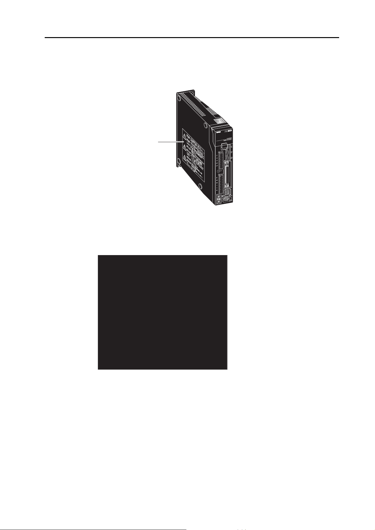
Location of Warning Label
The Servo Drive bears a warning label at the following location to provide handling warnings.
When handling the Servo Drive, be sure to observe the instructions provided on this label.
Warning label display location
(R88D-KTA5L)
Instructions on Warning Label
Disposal
When disposing of the battery, insulate it using tape and dispose of it by following the
applicable ordinance of your local government.
Dispose of the Servo Drive as an industrial waste.
OMNUC G5-SERIES AC SERVOMOTOR AND SERVO DRIVE USER'S MANUAL
13
Page 16
Items to Check after Unpacking
Items to Check after Unpacking
After unpacking, check the following items.
Is this the model you ordered?
Was there any damage sustained during shipment?
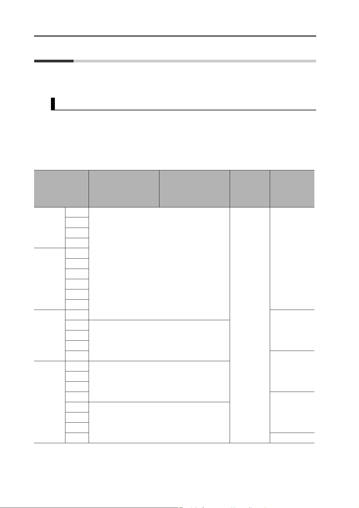
Accessories of This Product
Safety Precautions document × 1 copy
Connectors, mounting screws, mounting brackets, and other accessories other than those in
the table below are not supplied. They must be prepared by the customer.
The safety bypass connector is required when the safety function is not used. To use the
safety function, provide a Safety I/O Signal Connector separately.
If any item is missing or a problem is found such as Servo Drive damage, contact the
OMRON dealer or sales office where you purcha se d yo ur produ ct.
Specifications
Singlephase
100 VAC
Singlephase/3phase
200 VAC
3-phase
200 VAC
50 W
100 W
200 W
400 W
100 W
200 W
400 W
750 W
1 kW
1.5 kW
2 kW
3 kW
5 kW
7.5 kW
Connector for main
circuit power supply
terminals and control
circuit power supply
terminals
Included
−
Connector for External
Regeneration Resistor
connection terminals and
motor connection
terminals
Safety
bypass
connector
Included
Mounting
Brackets
−
Included
3-phase
400 VAC
14
15 kW
600 W
−
1 kW
Included
1.5 kW
2 kW
3 kW
Included
5 kW
−
7.5 kW
15 kW −
OMNUC G5-SERIES AC SERVOMOTOR AND SERVO DRIVE USER'S MANUAL
Page 17
Revision History
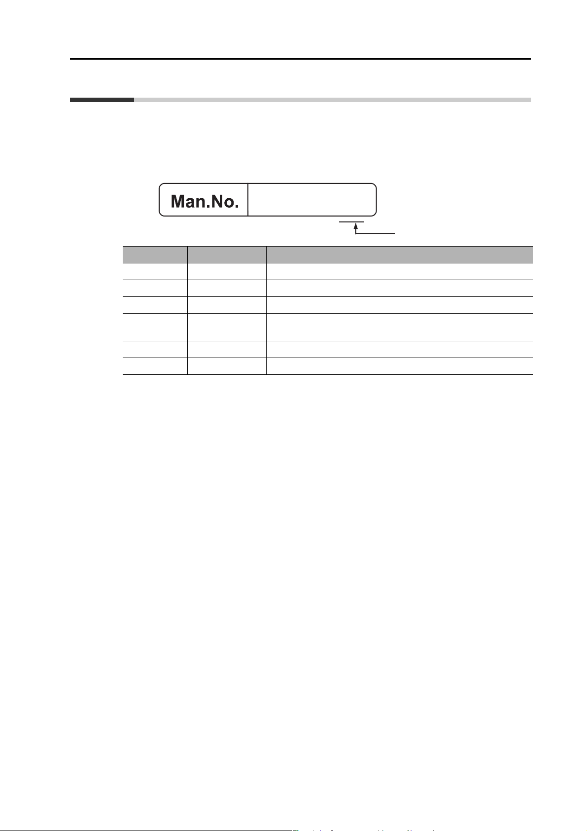
I571-E1-06
Revision code
The manual revision symbol is an alphabet appended at the end of the manual number found
in the bottom left-hand corner of the front or back cover.
Example
Revision code Revision date Revised content
01 September 2009 Original production
02 June 2010 Made corrections and added explanations.
03 January 2011 Added models and made corrections.
Revision History
04 September 2011
05 September 2015 Made corrections and added explanations.
06 January 2018 Made corrections and added explanations.
Added DC input ratings for the R88D-KT75H/-KT150H and made
corrections.
OMNUC G5-SERIES AC SERVOMOTOR AND SERVO DRIVE USER'S MANUAL
15
Page 18
Structure of This Document
Structure of This Document
This manual consists of the following chapters.
Read the necessary chapter or chapters referring to the following table.
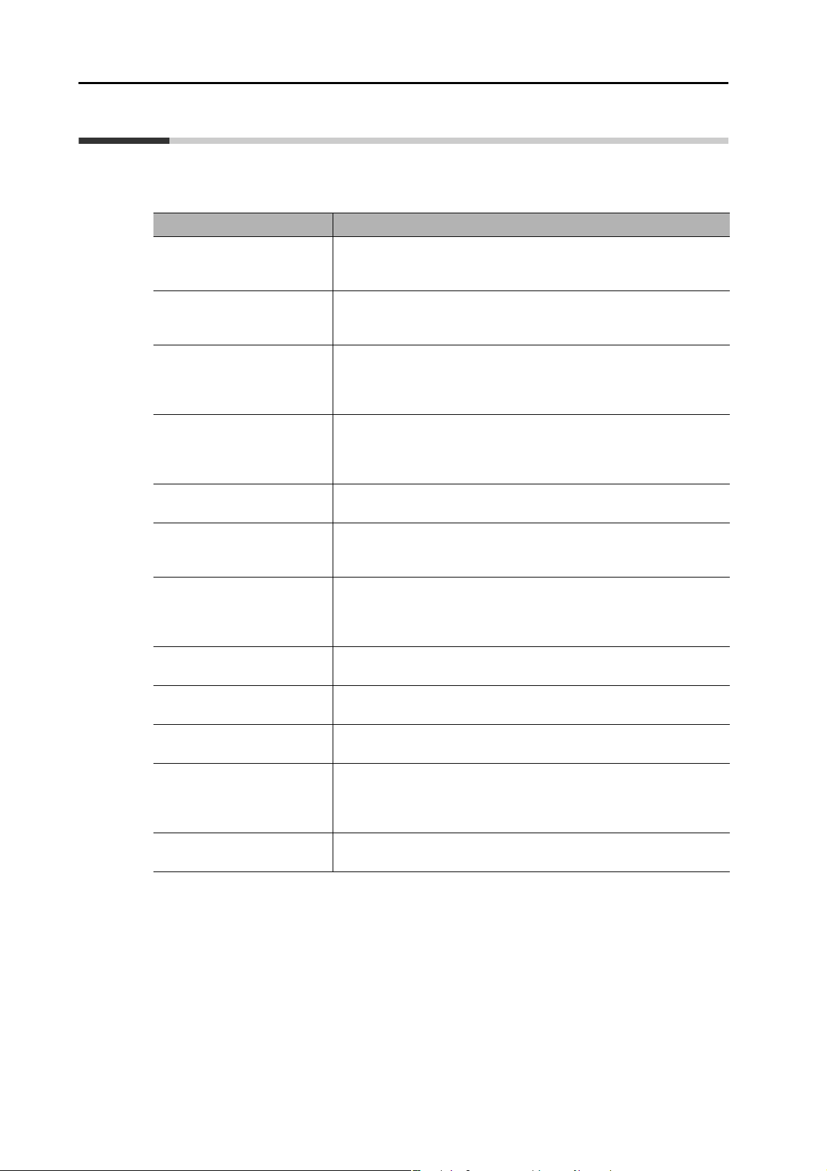
Outline
Features and
Chapter 1
Chapter 2
Chapter 3 Specifications
Chapter 4 System Design
System
Configuration
Standard Models
and External
Dimensions
This chapter explains the features of the Servo Drive, name of each
part, and applicable EC Directives and UL standards.
This chapter explains the models of Servo Drives, Servomotors, and
peripheral equipment, and provides the external dimensions and
mounting dimensions.
This chapter provides the general specifications, characteristics,
connector specifications, and I/O circuits of the Servo Drives as well as
the general specifications, characteristics, encoder specifications of
the Servomotors and other peripheral devices.
This chapter explains the installation conditions for the Servo Drive and
Servomotor, wiring methods including wiring conforming to EMC
Directives and regenerative energy calculation methods as well as the
performance of External Regeneration Resistors.
Chapter 5
Chapter 6
Chapter 7 Safety Function
Chapter 8
Chapter 9 Operation
Chapter 10
Chapter 11
Chapter 12 Appendix
Basic Control
Modes
Applied
Functions
Parameters
Details
Adjustment
Functions
Error and
Maintenance
This chapter explains an outline of operations available in various
control modes and explains the contents of setting.
This chapter gives outline of applied functions such as damping
control, electronic gears, gain switching and disturbance observer, and
explains the contents of setting.
This function stops the Servomotor based on a signal from a safety
controller or safety sensor.
An outline of the function is given together with operation and
connection examples.
This chapter explains the set value and contents of setting of each
parameter.
This chapter gives the operating procedures and explains how to
operate in each mode.
This chapter explains the functions, setting methods, and items to note
regarding various gain adjustments.
This chapter explains the items to check when problems occur, error
diagnosis using the alarm LED display and measures, error diagnosis
based on the operating condition and measures, and periodic
maintenance.
This chapter provides connection examples using OMRON's PLC and
Position Controller, as well as a list of parameters.
16
OMNUC G5-SERIES AC SERVOMOTOR AND SERVO DRIVE USER'S MANUAL
Page 19

OMNUC G5-SERIES AC SERVOMOTOR AND SERVO DRIVE USER'S MANUAL
17
Page 20

Table Of Contents
Introduction......................................................................................1
Terms and Conditions Agreement...................................................2
Items Requiring Acknowledgment...................................................4
Safety Precautions...........................................................................6
Items to Check after Unpacking.......................................................14
Revision History...............................................................................15
Structure of This Document.............................................................16
Chapter1 Features and System Configuration
1-1 Outline ................................................................................................1-1
1-2 System Configuration .........................................................................1-2
1-3 Names and Functions.........................................................................1-3
1-4 System Block Diagrams......................................................................1-5
1-5 Applicable Standards..........................................................................1-15
1-6 Unit Versions ......................................................................................1-18
Chapter2 Standard Models and External Dimensions
2-1 Servo System Configuration...............................................................2-1
2-2 How to Read Model Numbers.............................................................2-3
2-3 Standard Model Tables.......................................................................2-5
2-4 External and Mounting Dimensions....................................................2-25
2-5 EMC Filter Dimensions.......................................................................2-71
2-6 Dimensions of Mounting Brackets (L-Brackets for Rack Mounting) ...2-72
Chapter3 Specifications
3-1 Servo Drive Specifications..................................................................3-1
3-2 Overload Characteristics (Electronic Thermal Function) ....................3-58
3-3 Servomotor Specifications..................................................................3-59
3-4 Cable and Connector Specifications...................................................3-97
3-5 Servo Relay Units and Cable Specifications ......................................3-127
3-6 External Regeneration Resistor Specifications...................................3-146
3-7 EMC Filter Specifications....................................................................3-148
Chapter4 System Design
4-1 Installation Conditions.........................................................................4-1
4-2 Wiring..................................................................................................4-7
4-3 Wiring Conforming to EMC Directives................................................4-33
4-4 Regenerative Energy Absorption........................................................4-53
4-5 Large Load Inertia Adjustment and Dynamic Brake...........................4-61
4-6 Using DC Power.................................................................................4-62
18
OMNUC G5-SERIES AC SERVOMOTOR AND SERVO DRIVE USER'S MANUAL
Page 21

Table Of Contents
Chapter5 Basic Control Mode
5-1 Position Control..................................................................................5-1
5-2 Speed Control.....................................................................................5-7
5-3 Torque Control....................................................................................5-14
5-4 Internally Set Speed Control...............................................................5-19
5-5 Switching Control................................................................................5-23
5-6 Fully-closed Control............................................................................ 5-26
Chapter6 Applied Functions
6-1 Damping Control.................................................................................6-1
6-2 Adaptive Filter.....................................................................................6-5
6-3 Notch Filter.........................................................................................6-7
6-4 Electronic Gear Function....................................................................6-10
6-5 Encoder Dividing Function.................................................................. 6-14
6-6 Brake Interlock....................................................................................6-19
6-7 Gain Switching Function.....................................................................6-24
6-8 Torque Limit........................................................................................6-32
6-9 Sequence I/O Signal...........................................................................6-35
6-10 Forward and Reverse Drive Prohibition Functions............................. 6-41
6-11 Disturbance Observer Function.......................................................... 6-44
6-12 Gain Switching 3 Function..................................................................6-46
6-13 Friction Torque Compensation Function ............................................6-47
6-14 Inertia Ratio Switching Function......................................................... 6-49
6-15 Hybrid Vibration Suppression Function.............................................. 6-50
6-16 Feed-forward Function .......................................................................6-51
6-17 Instantaneous Speed Observer Function........................................... 6-55
Chapter7 Safety Function
7-1 Safe Torque OFF (STO) Function...................................................... 7-1
7-2 Operation Example.............................................................................7-4
7-3 Connection Example ..........................................................................7-6
Chapter8 Parameter Details
8-1 Basic Parameters...............................................................................8-1
8-2 Gain Parameters ................................................................................ 8-9
8-3 Vibration Suppression Parameters..................................................... 8-20
8-4 Analog Control Parameters................................................................ 8-25
8-5 Interface Monitor Setting Parameters.................................................8-37
8-6 Extended Parameters.........................................................................8-47
8-7 Special Parameters............................................................................ 8-60
19OMNUC G5-SERIES AC SERVOMOTOR AND SERVO DRIVE USER'S MANUAL
Page 22

Table Of Contents
Chapter9 Operation
9-1 Operational Procedure .......................................................................9-1
9-2 Preparing for Operation......................................................................9-2
9-3 Using the Front Display......................................................................9-6
9-4 Setting the Mode ................................................................................9-7
9-5 Trial Operation....................................................................................9-33
Chapter10 Adjustment Functions
10-1 Gain Adjustment.................................................................................10-1
10-2 Realtime Autotuning...........................................................................10-3
10-3 Manual Tuning....................................................................................10-10
Chapter11 Troubleshooting and Maintenance
11-1 Troubleshooting..................................................................................11-1
11-2 Warning List........................................................................................11-4
11-3 Alarm List............................................................................................11-5
11-4 Troubleshooting..................................................................................11-10
11-5 Periodic Maintenance.........................................................................11-27
Chapter12 Appendix
12-1 Connection Examples.........................................................................12-1
12-2 Parameter List.................................................................................... 12-11
Index
20
OMNUC G5-SERIES AC SERVOMOTOR AND SERVO DRIVE USER'S MANUAL
Page 23

Features and System Configuration
This chapter explains the features of the Servo Drive, name of each part, and
applicable EC Directives and UL standards.
1
1-1 Outline ...........................................................................1-1
Outline of the OMNUC G5 Series...................................................1-1
Features of OMNUC G5-series Servo Drives.................................1-1
1-2 System Configuration . .................................................1-2
1-3 Names and Functions ..................................................1-3
Servo Drive Part Names.................................................................1-3
Servo Drive Functions..................................................................... 1-4
1-4 System Block Diagrams...............................................1-5
1-5 Applicable Standards.................................................1-15
EC Directives................................................................................1-15
UL and cUL Standards..................................................................1-15
Korean Radio Regulations (KC)....................................................1-16
SEMI F47......................................................................................1-17
1-6 Unit Versions...............................................................1-18
Confirmation Method.....................................................................1-18
Unit Versions.................................................................................1-18
OMNUC G5-SERIES AC SERVOMOTOR AND SERVO DRIVE USER'S MANUAL
Page 24

1
1-1 Outline
1-1 Outline
Outline of the OMNUC G5 Series
With the OMNUC G5 Series, you can perform fully-closed control in addition to position control,
speed control and torque control.
Various models are available supporting wide-ranging motor capacities from 50 W to 15 kW and
input power supplies from 100 to 400 V. You will surely find a model that best suits your application.
Motors with high-resolution 20-bit incremental encoders and 17-bit absolute/incremental
encoders are available as standard models.
The OMNUC G5 Series features realtime autotuning function and adaptive filter function that
automatically perform complicated gain adjus tments. A notch filter can also be aut omatically
set to suppress machine vibration by reducing machine resonance during operation.
The damping control function of the Servomotor and Servo Drive realizes stable stopping
performance in a mechanism which vibrates because of the low rigidity of the load.
Features of OMNUC G5-series Servo Drives
OMNUC G5-series Servo Drives have the following features.
Switching between Seven Control Modes
You can switch between seven control modes: 1) Position Control Mode, 2) Speed Control
Mode, 3) Torque Control Mode, 4) Position and Speed Control Mode, 5) Position and Torque
Control Mode, 6) Speed and Torque Control Mode, and 7) Fully-closed Contro l Mode. Desired
modes can be selected with the flexible drive according to your need. A single drive supports
various applications.
Features and System Configuration
Achievement of Accurate Positioning by Fully-closed Control
Feedbacks from the external encoder connected to the motor is used to accurately control positions.
Accordingly, position control is not affected by deviation caused by ball screws or temperature.
Wide Range of Power Supplies to Meet Any Need
The OMNUC G5 Series now has models supporting 400 V for use with large equipment, at
overseas facilities and in wide-ranging applications and environment. Since the utilization ratio
of facility equipment also increases, the TCO (total cost of ownership) will come down.
Safe Torque OFF (STO) Function to Ensure Safety
1-1
You can cut off the motor current to stop the motor based on a signal from an emergen cy stop
button or other safety equipment. This can be used for an emergency stop circuit that is
compliant with safety standards without using an exte rn al co nta ctor.
Suppressing Vibration of Low-rigidity Mechanisms during Acceleration/Deceleration
The damping control function suppresses vibration of low-rigidity mechanisms or devices
whose tips tend to vibrate.
Two damping filters are provided to enable switching the damping frequency automatically
according to the rotation direction and also via an external signal. In addition, the settings can
be made easily by setting the damping frequency and filter values.
OMNUC G5-SERIES AC SERVOMOTOR AND SERVO DRIVE USER'S MANUAL
Page 25
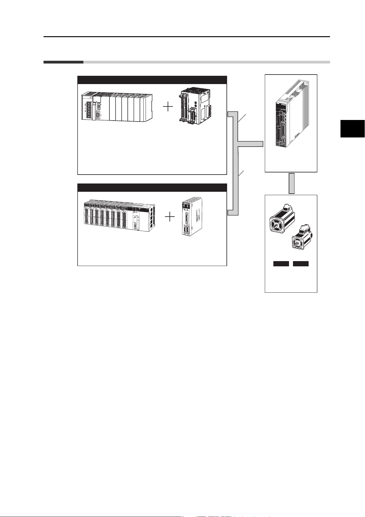
1-2 System Configuration
OMNUC G5 Series
AC Servomotor
R88D-KT@
OMNUC G5 Series
AC Servomotor
R88M-K@
INC ABS
Pulse train
Analog
voltage
SYSMAC + Position Control Unit (Pulse Train Output Type)
Programmable
Controller
SYSMAC CJ/CS
Position Control Unit
CJ1W-NC113/213/413
CJ1W-NC133/233/433
CJ1W-NC214/414
CJ1W-NC234/434
CS1W-NC113/213/413
CS1W-NC133/233/433
C200HW-NC113/213/413
Controller (Voltage Output Type)
Programmable
Controller
SYSMAC CS
Motion Control Unit
CS1W-MC221/421 (-V1)
PA202
POWE
R
INPUT
AC100
-240V
L2/N
L1
NC
NC
PERIP
HERA
L
ER
R/AL
M
RUN
IN
H
CO
M
M
P
RPH
L
CONTROLLER
CJ1
G-C
PU44
SYSM
AC
PROGRAMMABLE
PORT
OPEN
BUS
Y
M
CP
WR
MACH
x10
1
x10
0
No.
NC41
4
CN1
CN2
R
UN
A1
1
2
B1
A
2
B2
A3
3 4
B
3
A
4
B4
A
S
B
S
SY
NC
ERC
ER
H
AXIS1
AXIS2
CN3
CN4
AXIS2 AXIS1
1-2 System Configuration
1
Features and System Configuration
The following units support a motor with absolute encoder:
CJ1W-NC214/414
CJ1W-NC234/434
CS1W-MC221/421 (-V1)
OMNUC G5-SERIES AC SERVOMOTOR AND SERVO DRIVE USER'S MANUAL
1-2
Page 26

1
Display
Operation area
USB connector (CN7)
Expansion connector (CN3)
Analog monitor connector (CN5)
Motor connection
terminals (U, V and W)
Control circuit
power supply terminals
(L1C and L2C)
Main circuit
power supply terminals
(L1, L2, and L3)
External Regeneration
Resistor connection
terminals (B1, B2, and B3)
Protective ground terminals
Control I/O connector (CN1)
Safety connector (CN8)
External encoder connector (CN4
Encoder connector (CN2)
Charge lamp
1-3 Names and Functions
1-3 Names and Functions
Servo Drive Part Names
Features and System Configuration
1-3
OMNUC G5-SERIES AC SERVOMOTOR AND SERVO DRIVE USER'S MANUAL
Page 27

Servo Drive Functions
Display
A 6-digit 7-segment LED display shows the drive status, alarm codes, parameters, and other
information.
1-3 Names and Functions
Operation Area
Monitors the parameter setting and drive condition.
Charge Lamp
Lights when the main circuit power supply is turned ON.
Control I/O Connector (CN1)
Used for command input signals and I/O signals.
Encoder Connector (CN2)
Connector for the encoder installed in the Servomotor.
Expansion Connector (CN3)
A spare connector for expansion. Do not connect anything.
1
Features and System Configuration
External Encoder Connector (CN4)
Connector for an encoder signal used during fully-closed control.
Analog monitor Connector (CN5)
You can use a special cable to monitor values, such as the motor rotation speed, torque
command value, etc.
USB Connector (CN7)
Communications connector for the computer.
Safety Connector (CN8)
Connector for safety devices.
If no safety devices are used, keep the factory-set safety bypass connector installed.
OMNUC G5-SERIES AC SERVOMOTOR AND SERVO DRIVE USER'S MANUAL
1-4
Page 28
1
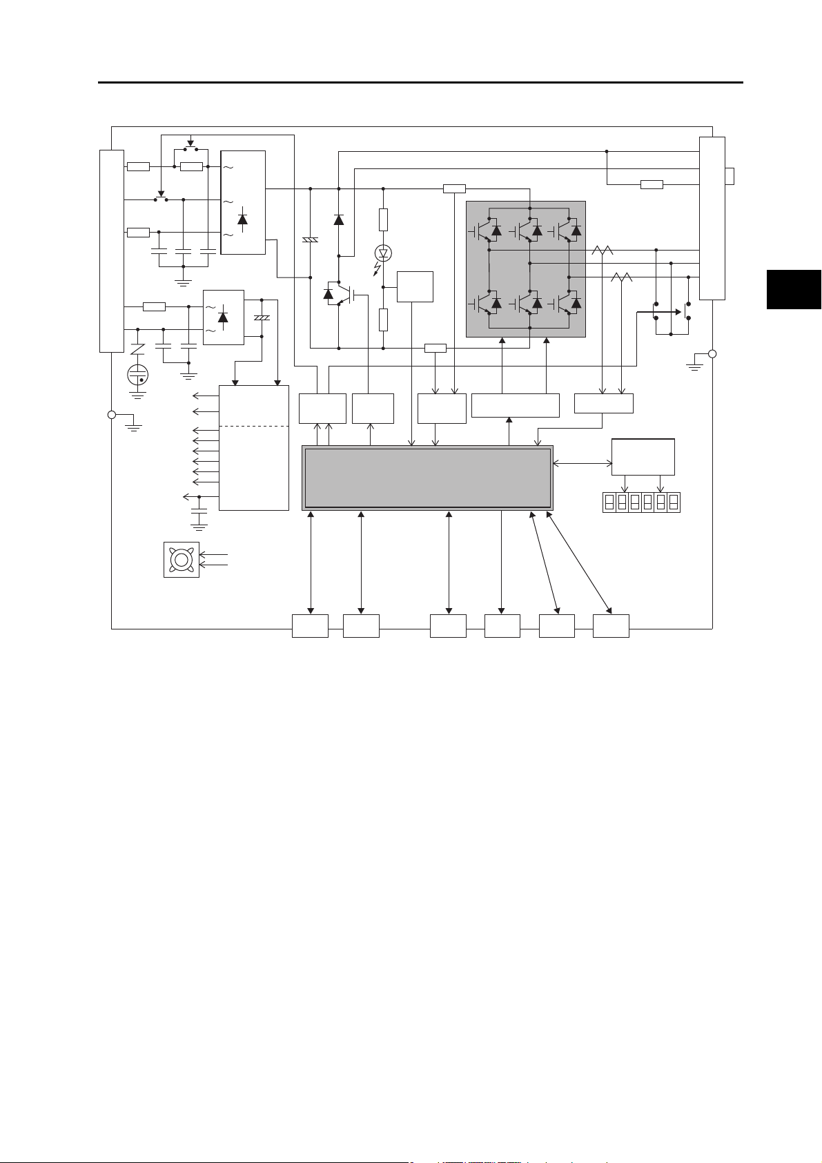
CN2 CN4 CN5 CN7 CN8CN1
Display and
setting circuit
area
Gate drive
SW power
supply main
circuit control
Internal
control power
supply
FG
L2C
L1C
L3
L2
L1
FUSE
FUSE
FUSE
CN A
+
-
+
-
15 V
G1
5 V
2.5 V
1.5 V
±12 V
E5 V
G2
3.3 V
Overcurrent
detection
Current detection
Voltage
detection
Regeneration
control
Relay
drive
FG
Control
interface
B1
B2
B3
CN B
U
V
W
MPU & ASIC
Position, speed, and torque calculation control area
• PWM control
Encoder
External
encoder
Analog
monitor
USB
Safety
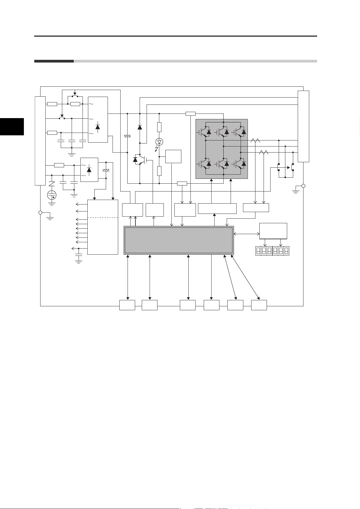
1-4 System Block Diagrams
1-4 System Block Diagrams
R88D-KTA5L/-KT01L/-KT02L/-KT01H/-KT02H/-KT04H
Features and System Configuration
1-5
OMNUC G5-SERIES AC SERVOMOTOR AND SERVO DRIVE USER'S MANUAL
Page 29
R88D-KT04L/-KT08H/-KT10H/-KT15H
FG
L2C
L1C
L3
L2
L1
FUSE
FUSE
FUSE
CN A
15 V
G1
5 V
2.5 V
1.5 V
E5 V
G2
3.3 V
FG
CN2 CN4 CN5 CN7
B1
B2
B3
CN B
U
V
W
CN8 CN1
Display and
setting circuit
area
Gate drive
SW power
supply main
circuit control
Internal
control power
supply
+
−
+
−
±12 V
Overcurrent
detection
Current detection
Voltage
detection
Regeneration
control
Relay
drive
Control
interface
MPU & ASIC
Position, speed, and torque calculation control area
• PWM control
Encoder
External
encoder
Analog
monitor
USB
Safety
Internal Regeneration
Resistor
Axial-flow fan
(except for the
R88D-KT04L/-KT08H)
1-4 System Block Diagrams
1
Features and System Configuration
OMNUC G5-SERIES AC SERVOMOTOR AND SERVO DRIVE USER'S MANUAL
1-6
Page 30

1
FG
L2C
L1C
L3
L2
L1
FUSE
FUSE
FUSE
CN A
15V
G1
5V
2.5V
1.5V
±12V
E5V
G2
3.3V
FG
CN2 CN4 CN5 CN7
B1
B2
B3
NC
CN C
CN B
CN8
USB
CN1
U
V
W
Display and
setting circuit
area
Gate drive
SW power
supply main
circuit control
Internal
control power
supply
Overcurrent
detection
Current detection
Voltage
detection
Regeneration
control
Relay
drive
Control
interface
MPU & ASIC
Position, speed, and torque calculation control area
• PWM control
Encoder
External
encoder
Analog
monitor
Safety
Internal Regeneration
Resistor
Axial-flow fan
1-4 System Block Diagrams
R88D-KT20H
Features and System Configuration
1-7
OMNUC G5-SERIES AC SERVOMOTOR AND SERVO DRIVE USER'S MANUAL
Page 31

R88D-KT30H/-KT50H
FG
L2C
L1C
L3
L2
L1
FUSE
FUSE
FUSE
15 V
G1
5 V
2.5 V
1.5 V
E5 V
G2
3.3 V
FG
CN2 CN4 CN5 CN7
B1
B2
B3
NC
CN B
U
V
W
CN8 CN1
Display and
setting circuit
area
Gate drive
SW power
supply main
circuit control
Internal
control power
supply
+
-
+
-
±12 V
Overcurrent
detection
Current detection
Voltage
detection
Regeneration
control
Relay
drive
Control
interface
MPU & ASIC
Position, speed, and torque calculation control area
• PWM control
Encoder
External
encoder
Analog
monitor
USB
Safety
Internal Regeneration Resistor
Axial-flow fan
1-4 System Block Diagrams
1
Features and System Configuration
OMNUC G5-SERIES AC SERVOMOTOR AND SERVO DRIVE USER'S MANUAL
1-8
Page 32

1
FG
L2C
L1C
L3
L2
L1
FUSE
FUSE
FUSE
15 V
G1
5 V
2.5 V
1.5 V
E5 V
G2
3.3 V
FG
CN2 CN4 CN5 CN7
B1
B2
N
U
V
W
CN8CN1
DB1
DB2
DB3
DB4
Display and
setting circuit
area
Gate drive
SW power
supply main
circuit control
Internal
control power
supply
+
-
+
-
±12 V
Overcurrent
detection
Current detection
Voltage
detection
Regeneration
control
Relay
drive
Control
interface
MPU & ASIC
Position, speed, and torque calculation control area
• PWM control
Encoder
External
encoder
Analog
monitor
USB
Safety
Axial-flow fan × 3
Fuse
TB1
TB1
TB2
TB1
TB2
1-4 System Block Diagrams
R88D-KT75H
Features and System Configuration
1-9
OMNUC G5-SERIES AC SERVOMOTOR AND SERVO DRIVE USER'S MANUAL
Page 33

R88D-KT150H
FG
L2C
L1C
L3
L2
L1
FUSE
FUSE
FUSE
15 V
G1
5 V
2.5 V
1.5 V
E5 V
G2
3.3 V
FG
CN2 CN4 CN5 CN7
B1
B2
N
U
V
W
CN8 CN1
DB1
DB2
Display and
setting circuit
area
Gate drive
SW power
supply main
circuit control
Internal
control power
supply
+
-
+
-
±12 V
Overcurrent
detection
Current detection
Voltage
detection
Regeneration
control
Relay
drive
Control
interface
MPU & ASIC
Position, speed, and torque calculation control area
• PWM control
Encoder
External
encoder
Analog
monitor
USB
Safety
Axial-flow fan × 4
Fuse
TB2
TB2
TB1
TB2
TB1
1-4 System Block Diagrams
1
Features and System Configuration
OMNUC G5-SERIES AC SERVOMOTOR AND SERVO DRIVE USER'S MANUAL
1-10
Page 34

1
FG
0 V
24 V
L3
L2
L1
FUSE
FUSE
FUSE
15 V
G1
5 V
2.5 V
1.5 V
E5 V
G2
3.3 V
FG
CN2 CN4 CN5 CN7
B1
B2
B3
NC
U
V
W
CN8 CN1
DC-DC
Display and
setting circuit
area
Gate drive
SW power
supply main
circuit control
Internal
control power
supply
+
-
+
-
±12 V
Overcurrent
detection
Current detection
Voltage
detection
Regeneration
control
Relay
drive
Control
interface
MPU & ASIC
Position, speed, and torque calculation control area
• PWM control
Encoder
External
encoder
Analog
monitor
USB
Safety
Internal Regeneration Resistor
Axial-flow fan
+
-
1-4 System Block Diagrams
R88D-KT06F/-KT10F/-KT15F/-KT20F
Features and System Configuration
1-11
OMNUC G5-SERIES AC SERVOMOTOR AND SERVO DRIVE USER'S MANUAL
Page 35

R88D-KT30F/-KT50F
FG
0 V
24 V
L3
L2
L1
FUSE
FUSE
FUSE
15 V
G1
5 V
2.5 V
1.5 V
E5 V
G2
3.3 V
FG
CN2 CN4 CN5 CN7
B1
B2
B3
NC
U
V
W
CN8 CN1
DC-DC
Display and
setting circuit
area
Gate drive
SW power
supply main
circuit control
Internal
control power
supply
+
-
+
-
±12 V
Overcurrent
detection
Current detection
Voltage
detection
Regeneration
control
Relay
drive
Control
interface
MPU & ASIC
Position, speed, and torque calculation control area
• PWM control
Encoder
External
encoder
Analog
monitor
USB
Safety
Internal Regeneration Resistor
Axial-flow fan
+
-
TB2
TB2
TB2
TB1
1-4 System Block Diagrams
1
Features and System Configuration
OMNUC G5-SERIES AC SERVOMOTOR AND SERVO DRIVE USER'S MANUAL
1-12
Page 36

1
FG
0 V
24 V
L3
L2
L1
FUSE
FUSE
FUSE
15 V
G1
5 V
2.5 V
1.5 V
E5 V
G2
3.3 V
FG
CN2 CN4 CN5 CN7
B1
B2
NC
U
V
W
CN8 CN1
DB1
DB2
DB3
DB4
DC-DC
Display and
setting circuit
area
Gate drive
SW power
supply main
circuit control
Internal
control power
supply
+
-
+
-
±12 V
Overcurrent
detection
Current detection
Voltage
detection
Regeneration
control
Relay
drive
Control
interface
MPU & ASIC
Position, speed, and torque calculation control area
• PWM control
Encoder
External
encoder
Analog
monitor
USB
Safety
Axial-flow fan × 3
-
+
Fuse
TB1
TB1
TB2
TB1
TB2
1-4 System Block Diagrams
R88D-KT75F
Features and System Configuration
1-13
OMNUC G5-SERIES AC SERVOMOTOR AND SERVO DRIVE USER'S MANUAL
Page 37

R88D-KT150F
FG
0 V
24 V
L3
L2
L1
FUSE
FUSE
FUSE
15 V
G1
5 V
2.5 V
1.5 V
E5 V
G2
3.3 V
FG
CN4 CN5 CN7
B1
B2
NC
U
V
W
CN8
DC-DC
CN2 CN1
DB1
DB2
Display and
setting circuit
area
Gate drive
SW power
supply main
circuit control
Internal
control power
supply
+
-
+
-
±12 V
Overcurrent
detection
Current detection
Voltage
detection
Regeneration
control
Relay
drive
Control
interface
MPU & ASIC
Position, speed, and torque calculation control area
• PWM control
Encoder
External
encoder
Analog
monitor
USB
Safety
Axial-flow fan × 4
+
-
Fuse
TB2
TB2
TB1
TB1
TB2
1-4 System Block Diagrams
1
Features and System Configuration
OMNUC G5-SERIES AC SERVOMOTOR AND SERVO DRIVE USER'S MANUAL
1-14
Page 38

1-5 Applicable Standards
1-5 Applicable Standards
EC Directives
1
EC
Directives
Low
Voltage
Directive
EMC
Directives
Machinery
Directive
Note. To conform to EMC directives, the Servomotor and Servo Drive must be installed under the conditions described
in "4-3 Wiring Conforming to EMC Directives" (P.4-33).
Product Applicable standards
AC Servo Drive EN 61800-5-1
AC Servomotor EN60034-1/-5
AC Servo Drive EN 55011 class A group 1
AC Servo Drive EN954-1 (Category 3)
UL and cUL Standards
Features and System Configuration
IEC61800-3
EN61000-6-2
EN ISO13849-1: 2008 (Category 3) (PLc,d)
ISO13849-1: 2006 (Category 3) (PLc,d)
EN61508 (SIL2)
EN62061 (SIL2)
EV61800-5-2 (STO)
IEC61326-3-1 (SIL2)
Standard Product Applicable standards File number
UL
standards
CSA
standards
*1: The R88D-KT20@ and lower capacity Servo Drives are UL-listed.
The R88D-KT30@ and higher capacity Servo Drives are UL-recognized.
*2: Applies to 1,500-r/min Servomotors of 7.5 to 15 kW and 1,000-r/min Servomotors of 4.5 to 6 kW.
AC Servo Drive UL508C
AC Servomotor UL1004-1 E331224
UL1004-1, UL1004-6
AC Servo Drive CSA C22.2 No. 14 E179149
AC Servomotor CSA C22.2 No. 100 E331224
E179149
E331224
*1
*2
1-15
OMNUC G5-SERIES AC SERVOMOTOR AND SERVO DRIVE USER'S MANUAL
Page 39

1-5 Applicable Standards
The Servo Drives and Servomotors comply with UL 508C (file No. E179149) as long as the
following installation conditions 1 and 2 are met.
(1) Use the Servo Drive in a pollution degree 1 or 2 environment as de fined in IEC 60664-
1 (example: installation in an IP54 control panel).
(2) Be sure to connect a circuit breaker or fuse, which is a UL-listed product with LISTED
and mark, between the power supply and noise filter.
Refer to the following table for the rated current of the circuit breaker or fuse .
Use copper wiring with a temperature rating of 75°C or higher.
Drive model Circuit breaker (rated current) (A)
R88D-KT01L 10
R88D-KT02L 10
1
R88D-KT04L 10
R88D-KT01H 10
R88D-KT02H 10
R88D-KT04H 10
R88D-KT08H 15
R88D-KT10H 15
R88D-KT15H 20
R88D-KT20H 30
R88D-KT30H 50
R88D-KT50H 50
R88D-KT75H 60
R88D-KT150H
R88D-KT06F 15
R88D-KT10F 15
R88D-KT15F 15
R88D-KT20F 20
R88D-KT30F 30
100/125 *
Features and System Configuration
1
R88D-KT50F 30
R88D-KT75F 30
R88D-KT150F
*1: 100 A when used in combination with the R88M-K11K015T-@. 125A when used in combination with
the R88M-K15K015T-@.
*2: 50 A when used in combination with the R88M-K11K015C-@. 60 A when used in combination with the
R88M-K15K015C-@.
50/60 *
Korean Radio Regulations (KC)
The G5-series Servo Drives comply with the Korean Radio Regulations (KC).
The G5-series Servomotors and Linear Motors are exempt from the Korean Radio
Regulations (KC).
OMNUC G5-SERIES AC SERVOMOTOR AND SERVO DRIVE USER'S MANUAL
2
1-16
Page 40

1
1-5 Applicable Standards
SEMI F47
Some Servo Drives conform to the SEMI F47 standard for momentary power interruptions
(voltage sag immunity) for no-load or light-load operation.
This standard applies to semiconductor manufacturing equipment.
Note 1. It does not apply to Servo Drivers with single-phase 100-V specifications or with
24-VDC specifications for the control power input.
Note 2. Always perform evaluation testing for SEMI F47 compliance in the actual system.
Features and System Configuration
1-17
OMNUC G5-SERIES AC SERVOMOTOR AND SERVO DRIVE USER'S MANUAL
Page 41

1-6 Unit Versions
(R88D-KTA5L)
Nameplate
location
Unit V ersion
Here, the unit version is 1.2.
Product Nameplate
The G5-series Servo Drive uses unit versions.
Unit versions are used to manage differences in supported functions when product upgrades
are made.
Confirmation Method
1-6 Unit Versions
The unit version of a G5-series Servo Drive is given on the product’s nameplate as shown
below.
Unit Versions
1
Features and System Configuration
Unit version Upgraded content
Not indicated New release Ver. 1.80 or higher
Alarm 27.2 detection conditions have been
Ver.1.1
Ver.1.2
OMNUC G5-SERIES AC SERVOMOTOR AND SERVO DRIVE USER'S MANUAL
changed to support the increase of encoder
resolution in the G series.
European area compliance
No changes to existing Ver. 1.1 functions
Supported
CX-Drive versions
Ver. 1.80 or higher
Ver. 1.80 or higher
1-18
Page 42

Page 43

Standard Models and External Dimensions
2
This chapter explains the models of Servo Dr ives, Servomotors, and peripher al
equipment, and provides the external dimensions and mounting dimensions.
2-1 Servo System Configuration .......................................2-1
2-2 How to Read Model Numbers......................................2-3
Servo Drive.....................................................................................2-3
Servomotor ..................................................................................... 2-4
2-3 Standard Model Tables ................................................2-5
Servo Drive Model Table ................................................................ 2-5
Servomotor Model Tables...............................................................2-6
Servo Drive and Servomotor Combination Tables.................... ... .2-11
Peripheral Equipment and Cable Model Tables ...........................2-13
2-4 External and Mounting Dimensions..........................2-25
Servo Drive Dimensions ...............................................................2-25
Servomotor Dimensions................................................................2-43
External Regeneration Resistor Dimensions ................................2-70
2-5 EMC Filter Dimensions...............................................2-71
2-6 Dimensions of Mounting Brackets
(L-Brackets for Rack Mounting)................................2-72
OMNUC G5-SERIES AC SERVOMOTOR AND SERVO DRIVE USER'S MANUAL
Page 44
2
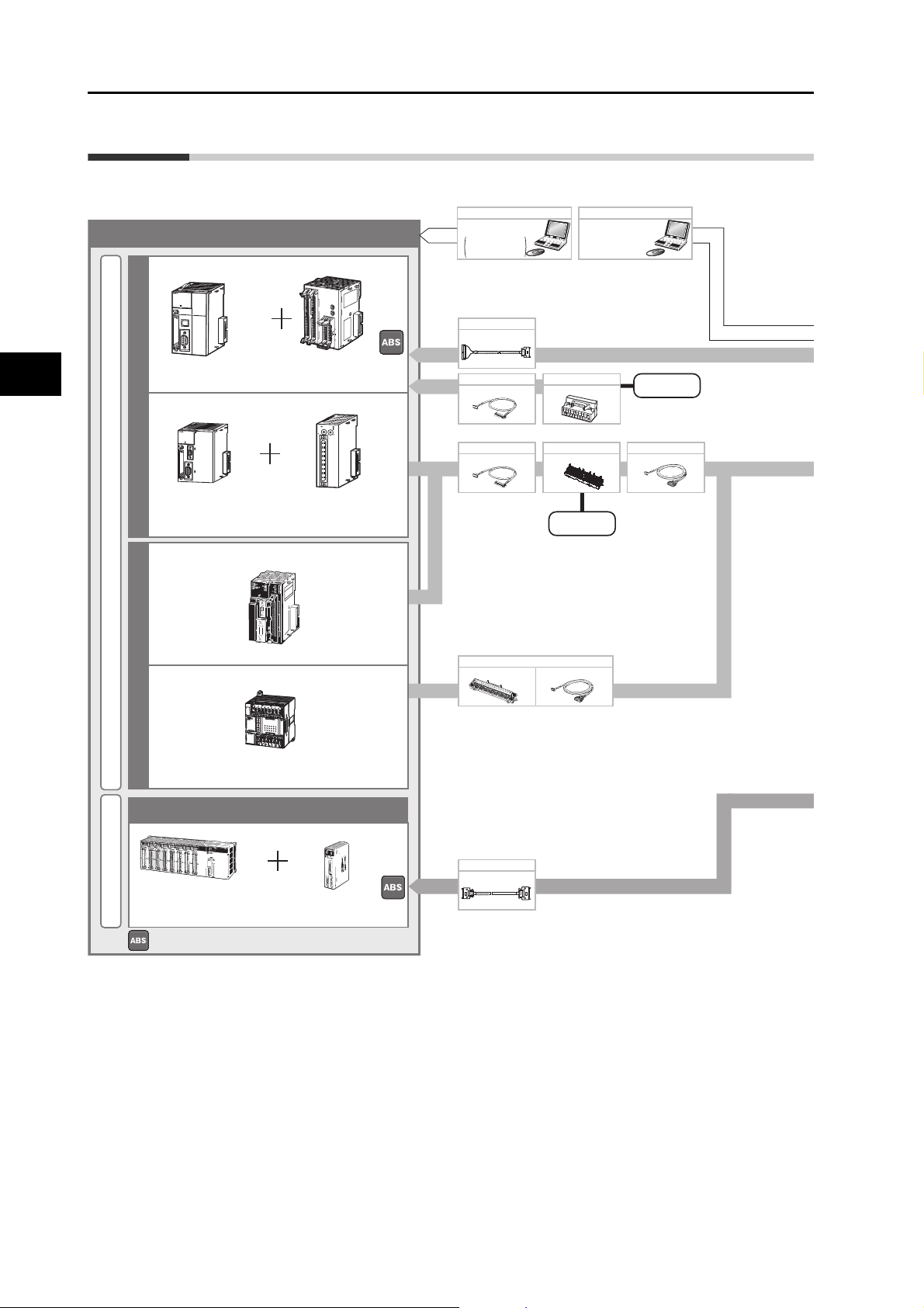
Controller
SYSMAC + Controller (Analog output type)
Position Control UnitCPU Unit
Pulse Train CommandsAnalog Commands
Pulse Train Commands/Feedback Signals
External Signal
External Signal
Analog Commands/Feedback Signals
Pulse Train Commands
•
CX-One FA Integrated
Tool Package
Including CX-Programmer
and CX-Position
and CX-Motion
Support Software
•
CX-One FA Integrated
Tool Package
(Including CX-Drive)
•
CX-Drive
WS02-DRVC1
Support Software
Programmable
Controller
SYSMAC CJ2
High-speed type
Position Control Unit (NC)
CJ1W-NC214/414
CJ1W-NC234/434
Standard type
Programmable
Controller
SYSMAC CJ1/CS1
Position Control Unit (NC)
CJ1W-NC@@3 CS1W-NC@@3
C200HW-NC@@3
CP1H/CP1L
CJ1M-CPU2
@
Motion Control Unit (MC)
CS1W-MC221/421 (-V1)
Programmable Controller
SYSMAC CS1
Available to build the Absolute System.
Built-in pulse
I/O function type
Built-in pulse
I/O function type
XW2Z-@-B@
XW2B-@XW2Z-@-A@
XW2Z-@@@J-G@
Direct connection cable for CJ1W-NC@@4
R88A-CPG
Control Cables (for Motion Control Unit)
Servo Drive CableServo Relay Unit
Position Control Unit Cable (NC)
XW2Z-@@@J-B24XW2@-50G@
Connector-Terminal Block Conversion Units and Cable
XW2Z-@X
Connector Terminal Block Conversion Unit
Position Control Unit Cable
XW2@-20G@
MACH
x10
1
x10
0
No.
NC
414
CN1
CN2
RUN
A1
1
2
B1
A2
B2
A3
3
4
B3
A4
B4
AS
BS
SYNCERC ERH
AXIS1AXI
S2
CN3
CN4
AXIS2 AXIS1
PER
IFHERA
L
E
RR/A
LM
R
UN
IN
H
C
OMM
P
R
PHL
CONTROLL
ER
CJ1G-C
P
U44
S
Y
SMA
C
PROGRA
MMAB
L
E
PORT
O
P
E
N
B
U
S
Y
M
CP
W
R
PERIPHERAL
ERR
/ALM
RUN
INH
COM
M
BKU
P
PRPHL
CONTROLLER
CPU64
CJ2H
SYSMA
C
PROGRAMM
ABLE
PORT
OPEN
B
U
S
Y
MC
PW
R
NC113
0
1
2
3
4
5
6
7
8
9
0
1
2
3
4
5
6
7
8
9
RUN
ERC
ERH
X
MAC
H
No.
10
1
10
0
20
1
1
20
X
CN1
2-1 Servo System Configuration
2-1 Servo System Configuration
Standard Models and External Dimensions
2-1
OMNUC G5-SERIES AC SERVOMOTOR AND SERVO DRIVE USER'S MANUAL
Page 45

2-1 Servo System Configuration
AC Servo Drive
Peripheral Devices
External
Regeneration
Resistors
R88A-RR
External encoder
AC Servomotors
•
OMNUC G5 Series Servo Drive
R88D-KT
•
OMNUC G5-series Servomotor
R88M-K
Motor power signals
Feedback Signals
Power Cables
•
Without Brake
R88A-CA@@@@@SR-E
•
With Brake
R88A-CA@@@@@BR-E
• Flexible Cables
Encoder Cables
Brake Cables (50 to 750 W max.)
•
Flexible Cables
R88A-CAKA@@@BR-E
Absolute Encoder Battery Cable
* Not required if a battery is connected
to the control connector (CN1).
(A battery is included with
model numbers ending in “BS”).
R88A-CRGD0R3C (-BS)
100 VAC
200 VAC
400 VAC
3,000 r/min
2,000 r/min
1,500 r/min
1,000 r/min
USB
communications
• 750 W or less:
R88A-CRKA@@@CR-E
• 1 kW or more:
R88A-CRKC@@@NR-E
●
Flexible Cables
2
Standard Models and External Dimensions
OMNUC G5-SERIES AC SERVOMOTOR AND SERVO DRIVE USER'S MANUAL
2-2
Page 46

2-2 How to Read Model Numbers
2-2 How to Read Model Numbers
Servo Drive
The Servo Drive model number tells the Servo Drive type, applicable Servomotor capacity,
power supply voltage, etc.
R88D-KT01H
2
OMNUC G5-series Servo Drive
Drive Type
: Pulse/analog typeT
Maximum Applicable Servomotor Capacity
A5
: 50 W
01
: 100 W
02
: 200 W
04
: 400 W
06
: 600 W
08
: 750 W
10
: 1 kW
15
: 1.5 kW
20
: 2 kW
30
: 3 kW
50
: 5 kW
75
: 7.5 kW
150
: 15 kW
Power Supply Voltage
: 100 VAC
L
: 200 VAC
H
: 400 VAC
F
Standard Models and External Dimensions
2-3
OMNUC G5-SERIES AC SERVOMOTOR AND SERVO DRIVE USER'S MANUAL
Page 47

Servomotor
R88M-K10030H-BOS2
OMNUC G5-series Servomotor
Servomotor Capacity
Rated Rotation Speed
050
100
200
400
600
750
900
1K0
1K5
2K0
3K0
4K0
4K5
5K0
6K0
7K5
11K0
15K0
: 50 W
: 100 W
: 200 W
: 400 W
: 600 W
: 750 W
: 900 W
: 1 kW
: 1.5 kW
: 2 kW
: 3 kW
: 4 kW
: 4.5 kW
: 5 kW
: 6 kW
: 7.5 kW
: 11 kW
: 15 kW
10
15
20
30
: 1,000 r/min
: 1,500 r/min
: 2,000 r/min
: 3,000 r/min
Applied V oltage
F
H
L
C
T
S
: 400 VAC (incremental encoder specifications)
: 200 VAC (incremental encoder specifications)
: 100 VAC (incremental encoder specifications)
: 400 VAC (absolute encoder specifications)
: 200 VAC (absolute encoder specifications)
: 100 VAC (absolute encoder specifications)
Options
Blank
B
O
S2
: Straight shaft, no key
: With brake
: With oil seal
: With key and tap
2-2 How to Read Model Numbers
2
Standard Models and External Dimensions
OMNUC G5-SERIES AC SERVOMOTOR AND SERVO DRIVE USER'S MANUAL
2-4
Page 48

2
2-3 Standard Model Tables
2-3 Standard Model Tables
Servo Drive Model Table
Specifications Model
Single-phase 100 VAC 50 W R88D-KTA5L
100 W R88D-KT01L
200 W R88D-KT02L
400 W R88D-KT04L
Single-phase/3-phase 200 VAC 100 W R88D-KT01H
200 W R88D-KT02H
400 W R88D-KT04H
Standard Models and External Dimensions
750 W R88D-KT08H
1 kW R88D-KT10H
1.5 kW R88D-KT15H
3-phase 200 VAC 2 kW R88D-KT20H
3 kW R88D-KT30H
5 kW R88D-KT50H
7.5 kW R88D-KT75H
15 kW R88D-KT150H
3-phase 400 VAC 600 W R88D-KT06F
1 kW R88D-KT10F
1.5 kW R88D-KT15F
2 kW R88D-KT20F
3 kW R88D-KT30F
5 kW R88D-KT50F
7.5 kW R88D-KT75F
15 kW R88D-KT150F
2-5
OMNUC G5-SERIES AC SERVOMOTOR AND SERVO DRIVE USER'S MANUAL
Page 49

Servomotor Model Tables
Without brakes
3,000-r/min Servomotors
Specifications
50 W R88M-K05030H R88M-K05030H-S2 R88M-K05030T R88M-K05030T-S2
100 W R88M-K10030L R88M-K10030L-S2 R88M-K10030S R88M-K10030S-S2
100 V
200 W R88M-K20030L R88M-K20030L-S2 R88M-K20030S R88M-K20030S-S2
400 W R88M-K40030L R88M-K40030L-S2 R88M-K40030S R88M-K40030S-S2
50 W R88M-K05030H R88M-K05030H-S2 R88M-K05030T R88M-K05030T-S2
With incremental encoder With absolute encoder
Straight shaft
without key
Straight shaft
with key and tap
Model
2-3 Standard Model Tables
Straight shaft
without key
Straight shaft
with key and tap
2
Standard Models and External Dimensions
100 W R88M-K10030H R88M-K10030H-S2 R88M-K10030T R88M-K10030T-S2
200 W R88M-K20030H R88M-K20030H-S2 R88M-K20030T R88M-K20030T-S2
400 W R88M-K40030H R88M-K40030H-S2 R88M-K40030T R88M-K40030T-S2
750 W R88M-K75030H R88M-K75030H-S2 R88M-K75030T R88M-K75030T-S2
200 V
1 kW R88M-K1K030H R88M-K1K030H-S2 R88M-K1K030T R88M-K1K030T-S2
1.5 kW R88M-K1K530H R88M-K1K530H-S2 R88M-K1K530T R88M-K1K530T-S2
2 kW R88M-K2K030H R88M-K2K030H-S2 R88M-K2K030T R88M-K2K030T-S2
3 kW R88M-K3K030H R88M-K3K030H-S2 R88M-K3K030T R88M-K3K030T-S2
4 kW R88M-K4K030H R88M-K4K030H-S2 R88M-K4K030T R88M-K4K030T-S2
5 kW R88M-K5K030H R88M-K5K030H-S2 R88M-K5K030T R88M-K5K030T-S2
750 W R88M-K75030F R88M-K75030F-S2 R88M-K75030C R88M-K75030C-S2
1 kW R88M-K1K030F R88M-K1K030F-S2 R88M-K1K030C R88M-K1K030C-S2
1.5 kW R88M-K1K530F R88M-K1K530F-S2 R88M-K1K530C R88M-K1K530C-S2
400 V
2 kW R88M-K2K030F R88M-K2K030F-S2 R88M-K2K030C R88M-K2K030C-S2
3 kW R88M-K3K030F R88M-K3K030F-S2 R88M-K3K030C R88M-K3K030C-S2
4 kW R88M-K4K030F R88M-K4K030F-S2 R88M-K4K030C R88M-K4K030C-S2
5 kW R88M-K5K030F R88M-K5K030F-S2 R88M-K5K030C R88M-K5K030C-S2
Note. Models with oil seals are also available.
OMNUC G5-SERIES AC SERVOMOTOR AND SERVO DRIVE USER'S MANUAL
2-6
Page 50

2-3 Standard Model Tables
With brakes
Model
2
Specifications
50 W R88M-K05030H-B R88M-K05030H-BS2 R88M-K05030T-B R88M-K05030T -BS2
100 W R88M-K10030L-B R88M-K10030L-BS2 R88M-K10030S-B R88M-K10030S-BS2
100 V
200 W R88M-K20030L-B R88M-K20030L-BS2 R88M-K20030S-B R88M-K20030S-BS2
400 W R88M-K40030L-B R88M-K40030L-BS2 R88M-K40030S-B R88M-K40030S-BS2
50 W R88M-K05030H-B R88M-K05030H-BS2 R88M-K05030T-B R88M-K05030T -BS2
100 W R88M-K10030H-B R88M-K10030H-BS2 R88M-K10030T-B R88M-K10030T-BS2
200 W R88M-K20030H-B R88M-K20030H-BS2 R88M-K20030T-B R88M-K20030T-BS2
400 W R88M-K40030H-B R88M-K40030H-BS2 R88M-K40030T-B R88M-K40030T-BS2
750 W R88M-K75030H-B R88M-K75030H-BS2 R88M-K75030T-B R88M-K75030T-BS2
200 V
1 kW R88M-K1K030H-B R88M-K1K030H-BS2 R88M-K1K030T-B R88M-K1K030T-BS2
1.5 kW R88M-K1K530H-B R88M-K1K530H-BS2 R88M-K1K530T-B R88M-K1K530T-BS2
2 kW R88M-K2K030H-B R88M-K2K030H-BS2 R88M-K2K030T-B R88M-K2K030T-BS2
3 kW R88M-K3K030H-B R88M-K3K030H-BS2 R88M-K3K030T-B R88M-K3K030T-BS2
4 kW R88M-K4K030H-B R88M-K4K030H-BS2 R88M-K4K030T-B R88M-K4K030T-BS2
5 kW R88M-K5K030H-B R88M-K5K030H-BS2 R88M-K5K030T-B R88M-K5K030T-BS2
With incremental encoder With absolute encoder
Straight shaft
without key
Straight shaft
with key and tap
Straight shaft
without key
Straight shaft
with key and tap
Standard Models and External Dimensions
750 W R88M-K75030F-B R88M-K75030F-BS2 R88M-K75030C-B R88M-K75030C-BS2
1 kW R88M-K1K030F-B R88M-K1K030F-BS2 R88M-K1K030C-B R88M-K1K030C-BS2
1.5 kW R88M-K1K530F-B R88M-K1K530F-BS2 R88M-K1K530C-B R88M-K1K530C-BS2
400 V
2 kW R88M-K2K030F-B R88M-K2K030F-BS2 R88M-K2K030C-B R88M-K2K030C-BS2
3 kW R88M-K3K030F-B R88M-K3K030F-BS2 R88M-K3K030C-B R88M-K3K030C-BS2
4 kW R88M-K4K030F-B R88M-K4K030F-BS2 R88M-K4K030C-B R88M-K4K030C-BS2
5 kW R88M-K5K030F-B R88M-K5K030F-BS2 R88M-K5K030C-B R88M-K5K030C-BS2
Note. Models with oil seals are also available.
2-7
OMNUC G5-SERIES AC SERVOMOTOR AND SERVO DRIVE USER'S MANUAL
Page 51

1,500-r/min and 2,000-r/min Servomotors
Without brakes
Specifications
1 kW R88M-K1K020H R88M-K1K020H-S2 R88M-K1K020T R88M-K1K020T-S2
1.5 kW R88M-K1K520H R88M-K1K520H-S2 R88M-K1K520T R88M-K1K520T-S2
2 kW R88M-K2K020H R88M-K2K020H-S2 R88M-K2K020T R88M-K2K020T-S2
3 kW R88M-K3K020H R88M-K3K020H-S2 R88M-K3K020T R88M-K3K020T-S2
200 V
4 kW R88M-K4K020H R88M-K4K020H-S2 R88M-K4K020T R88M-K4K020T-S2
5 kW R88M-K5K020H R88M-K5K020H-S2 R88M-K5K020T R88M-K5K020T-S2
7.5 kW --- --- R88M-K7K515T R88M-K7K515T-S2
11 kW --- --- R88 M-K11K015T R88M-K11K015T-S2
15 kW --- --- R88 M-K15K015T R88M-K15K015T-S2
400 W R88M-K40020F R88M-K40020F-S2 R88M-K40020C R88M-K40020C-BS2
2-3 Standard Model Tables
Model
With incremental encoder With absolute encoder
Straight shaft
without key
Straight shaft
with key and tap
Straight shaft
without key
Straight shaft
with key and tap
2
Standard Models and External Dimensions
600 W R88M-K60020F R88M-K60020F-S2 R88M-K60020C R88M-K60020C-BS2
1 kW R88M-K1K020F R88M-K1K020F-S2 R88M-K1K020C R88M-K1K020C-S2
1.5 kW R88M-K1K520F R88M-K1K520F-S2 R88M-K1K520C R88M-K1K520C-S2
2 kW R88M-K2K020F R88M-K2K020F-S2 R88M-K2K020C R88M-K2K020C-S2
400 V
3 kW R88M-K3K020F R88M-K3K020F-S2 R88M-K3K020C R88M-K3K020C-S2
4 kW R88M-K4K020F R88M-K4K020F-S2 R88M-K4K020C R88M-K4K020C-S2
5 kW R88M-K5K020F R88M-K5K020F-S2 R88M-K5K020C R88M-K5K020C-S2
7.5 kW --- --- R88M-K7K515C R88M-K7K515C-S2
11 kW --- --- R88M-K11K015C R88M-K11K015C-S2
15 kW --- --- R88M-K15K015C R88M-K15K015C-S2
Note 1. Models with oil seals are also available.
Note 2. The rated rotation speed of Servomotors of 7.5 to 15 kW is 1,500 r/min.
OMNUC G5-SERIES AC SERVOMOTOR AND SERVO DRIVE USER'S MANUAL
2-8
Page 52

2-3 Standard Model Tables
With brakes
Model
2
Specifications
1 kW R88M-K1K020H-B R88M-K1K020H-BS2 R88M-K1K020T-B R88M-K1K020T-BS2
1.5 kW R88M-K1K520H-B R88M-K1K520H-BS2 R88M-K1K520T-B R88M-K1K520T-BS2
2 kW R88M-K2K020H-B R88M-K2K020H-BS2 R88M-K2K020T-B R88M-K2K020T-BS2
3 kW R88M-K3K020H-B R88M-K3K020H-BS2 R88M-K3K020T-B R88M-K3K020T-BS2
200 V
4 kW R88M-K4K020H-B R88M-K4K020H-BS2 R88M-K4K020T-B R88M-K4K020T-BS2
5 kW R88M-K5K020H-B R88M-K5K020H-BS2 R88M-K5K020T-B R88M-K5K020T-BS2
7.5 kW --- --- R88M-K7K515T-B R88M-K7K515T-BS2
11 kW --- --- R88M-K11K015T -B R88M-K11K015T-S2
15 kW --- --- R88M-K15K015T -B R88M-K15K015T-S2
400 W R88M-K40020F-B R88M-K40020F-BS2 R88M-K40020C-B R88M-K40020C-BS2
600 W R88M-K60020F-B R88M-K60020F-BS2 R88M-K60020C-B R88M-K60020C-BS2
1 kW R88M-K1K020F-B R88M-K1K020F-BS2 R88M-K1K020C-B R88M-K1K020C-BS2
1.5 kW R88M-K1K520F-B R88M-K1K520F-BS2 R88M-K1K520C-B R88M-K1K520C-BS2
2 kW R88M-K2K020F-B R88M-K2K020F-BS2 R88M-K2K020C-B R88M-K2K020C-BS2
400 V
3 kW R88M-K3K020F-B R88M-K3K020F-BS2 R88M-K3K020C-B R88M-K3K020C-BS2
With incremental encoder With absolute encoder
Straight shaft
without key
Straight shaft
with key and tap
Straight shaft
without key
Straight shaft
with key and tap
Standard Models and External Dimensions
4 kW R88M-K4K020F-B R88M-K4K020F-BS2 R88M-K4K020C-B R88M-K4K020C-BS2
5 kW R88M-K5K020F-B R88M-K5K020F-BS2 R88M-K5K020C-B R88M-K5K020C-BS2
7.5 kW --- --- R88M-K7K515C-B R88M-K7K515C-BS2
11 kW --- --- R88M-K11K015C-B R88M-K11K015C-BS2
15 kW --- --- R88M-K15K015C-B R88M-K15K015C-BS2
Note 1. Models with oil seals are also available.
Note 2. The rated rotation speed of Servomotors of 7.5 to 15 kW is 1,500 r/min.
2-9
OMNUC G5-SERIES AC SERVOMOTOR AND SERVO DRIVE USER'S MANUAL
Page 53

1,000-r/min Servomotors
Without brakes
With brakes
2-3 Standard Model Tables
Model
Specifications
900 kW R88M-K9001 0H R88M-K90010H-S2 R88M-K90010T R88M-K9 0010T-S2
2 kW R88M-K2K010H R88M-K2K010H-S2 R88M-K2K010T R88M-K2K010T-S2
200 V
3 kW R88M-K3K010H R88M-K3K010H-S2 R88M-K3K010T R88M-K3K010T-S2
4.5 kW --- --- R88M-K4K510T R88M-K4K510T-S2
6 kW --- --- R88M-K6K010T R88M-K6K010T-S2
900 kW R88M-K9001 0F R88M-K90010F-S2 R88M-K90010C R88M-K90010C-S2
2 kW R88M-K2K010F R88M-K2K010F-S2 R88M-K2K010C R88M-K2K010C-S2
400 V
3 kW R88M-K3K010F R88M-K3K010F-S2 R88M-K3K010C R88M-K3K010C-S2
4.5 kW --- --- R88M-K4K510C R88M-K4K510C-S2
6 kW --- --- R88M-K6K010C R88M-K6K010C-S2
900 kW R88M-K9001 0H-B R88M-K90010H-BS2 R88M-K90010T-B R88M-K90010T-BS2
2 kW R88M-K2 K 010H-B R88M-K2K010H-BS2 R88M-K2K010T-B R88M-K2K010T-BS2
200 V
3 kW R88M-K3 K 010H-B R88M-K3K010H-BS2 R88M-K3K010T-B R88M-K3K010T-BS2
4.5 kW --- --- R88M-K4K510T-B R88M-K4K510T-BS2
6 kW --- --- R88M-K6K010T-B R88M-K6K010T-BS2
900 kW R88M-K9001 0F-B R88M-K90010F-BS2 R88M-K90010C-B R88M-K90010C-BS2
2 kW R88M-K2 K 010F-B R88M-K2K010F-BS2 R88M-K2K010C-B R88M-K2K010C-BS2
With incremental encoder With absolute encoder
Straight shaft
without key
Straight shaft
with key and tap
Straight shaft
without key
Straight shaft
with key and tap
2
Standard Models and External Dimensions
400 V
3 kW R88M-K3 K 010F-B R88M-K3K010F-BS2 R88M-K3K010C-B R88M-K3K010C-BS2
4.5 kW --- --- R88M-K4K510C-B R88M-K4K510C-BS2
6 kW --- --- R88M-K6K010C-B R88M-K6K010C-BS2
Note. Models with oil seals are also available.
OMNUC G5-SERIES AC SERVOMOTOR AND SERVO DRIVE USER'S MANUAL
2-10
Page 54

2-3 Standard Model Tables
Servo Drive and Servomotor Combination Tables
The tables in this section show the possible combinations of OMNUC G5-series Servo Drives
and Servomotors. The Servomotors and Servo Drives can only be used in the listed
combinations.
“-@” at the end of the motor model number is for options, such as the sha ft type, brake, oil seal
and key.
3,000-r/min Servomotors and Servo Drives
2
Voltage
Single-phase
100 V
Single-phase/
3-phase 100 V
Single-phase/
3-phase 200 V
3-phase 200 V
Servomotor
Rated
output
50 W R88M-K05030H-@ R88M-K05030T-@ R88D-KTA5L
100 W R88M-K10030L-@ R88M-K10030S-@ R88D-KT01L
200 W R88M-K20030L-@ R88M-K20030S-@ R88D-KT02L
400 W R88M-K40030L-@ R88M-K40030S-@ R88D-KT04L
50 W* R88M-K05030H-@ R88M-K05030T-@ R88D-KT01H
100 W R88M-K10030H-@ R88M-K10030T-@ R88D-KT01H
200 W R88M-K20030H-@ R88M-K20030T-@ R88D-KT02H
400 W R88M-K40030H-@ R88M-K40030T-@ R88D-KT04H
750 W R88M-K75030H-@ R88M-K75030T-@ R88D-KT08H
1 kW* R88M-K1K030H-@ R88M-K1K030T-@ R88D-KT15H
1.5 kW R88M-K1K530H-@ R88M-K1K530T-@ R88D-KT15H
2 kW R88M-K2K030H-@ R88M-K2K030T-@ R88D-KT20H
3 kW R88M-K3K030H-@ R88M-K3K030T-@ R88D-KT30H
4 kW* R88M-K4K030H-@ R88M-K4K030T-@ R88D-KT50H
5 kW R88M-K5K030H-@ R88M-K5K030T-@ R88D-KT50H
With incremental
encoder
With absolute
encoder
Servo Drive
Standard Models and External Dimensions
2-11
750 W* R88M-K75030F-@ R88M-K75030C-@ R88D-KT10F
1 kW* R88M-K1K030F-@ R88M-K1K030C-@ R88D-KT15F
1.5 kW R88M-K1K530F-@ R88M-K1K530C-@ R88D-KT15F
3-phase 400 V
2 kW R88M-K2K030F-@ R88M-K2K0
3 kW R8
4 kW* R88M-K4K030F-@ R88M-K4K030C-@ R88D-KT50F
5 kW R88M-K5K030F-@ R88M-K5K030C-@ R88D-KT50F
8M-K3K030F-@ R88M-K3K030C-@ R88D-KT30F
30C-@ R88D-KT20F
* Use these combination with caution because the Servo Drive and Se rvomotor h ave diffe rent
capacities.
OMNUC G5-SERIES AC SERVOMOTOR AND SERVO DRIVE USER'S MANUAL
Page 55

2-3 Standard Model Tables
1,500-r/min and 2,000-r/min Servomotors and Servo Drives
Servomotor
Voltage
Single-phase/
3-phase 200 V
Rated
output
1 kW R88M-K1K020H-@ R88M-K1K020T-@ R88D-KT10H
1.5 kW R88M-K1K520H-@ R88M-K1K520T-@ R88D-KT15H
2 kW R88M-K2K020H-@ R88M-K2K020T-@ R88D-KT20H
3 kW R88M-K3K020H-@ R88M-K3K020T-@ R88D-KT30H
4 kW* R88M-K4K020H-@ R88M-K4K020T-@ R88D-KT50H
With incremental
encoder
With absolute
encoder
Servo Drive
3-phase 200 V
3-phase 400 V
* Use these combination with caution because the Servo Drive and Servomotor have different capacities.
5 kW R88M-K5K020H-@ R88M-K5K020T-@ R88D-KT50H
7.5 kW --- R88M-K7K515T-@ R88D-KT75H
11 kW* --- R88M-K11K015T-@ R88D-KT150H
15 kW --- R88M-K15K015T-@ R88D-KT150H
400 W* R88M-K40020F -@ R88M-K40020C-@ R88D-KT06F
600 W R88M-K60020F-@ R88M-K60020C-@ R88D-KT06F
1 kW R88M-K1K020F-@ R88M-K1K020C-@ R88D-KT10F
1.5 kW R88M-K1K520F-@ R88M-K1K520C-@ R88D-KT15F
2 kW R88M-K2K020F-@ R88M-K2K020C-@ R88D-KT20F
3 kW R88M-K3K020F-@ R88M-K3K020C-@ R88D-KT30F
4 kW* R88M-K4K020F-@ R88M-K4K020C-@ R88D-KT50F
5 kW R88M-K5K020F-@ R88M-K5K020C-@ R88D-KT50F
7.5 kW --- R88M-K7K515C-@ R88D-KT75F
11 kW* --- R88M-K11K015C-@ R88D-KT150F
15 kW --- R88M-K15K015C-@ R88D-KT150F
2
Standard Models and External Dimensions
OMNUC G5-SERIES AC SERVOMOTOR AND SERVO DRIVE USER'S MANUAL
2-12
Page 56

2-3 Standard Model Tables
1,000-r/min Servomotors and Servo Drives
Voltage
Single-phase/
3-phase 200 V
3-phase 200 V
Rated
output
900 W* R88M-K90010H-@ R88M-K90010T-@ R88D-KT15H
2 kW* R88M-K2K010H-@ R88M-K2K010T-@ R88D-KT30H
3 kW* R88M-K3K010H-@ R88M-K3K010T-@ R88D-KT50H
4.5 kW* --- R88M-K4K510T-@ R88D-KT50H
Servomotor
With incremental
encoder
With absolute encoder
Servo Drive
2
6 kW* --- R88M-K6K010T-@ R88D-KT75H
900 W* R88M-K90010F-@ R88M-K90010C-@ R88D-KT15F
2 kW* R88M-K2K010F-@ R88M-K2K010C-@ R88D-KT30F
3-phase 400 V
3 kW* R88M-K3K010F-@ R88M-K3K010C-@ R88D-KT50F
4.5 kW* --- R88M-K4K510C-@ R88D-KT50F
6 kW* --- R88M-K6K010C-@ R88D-KT75F
* Use these combination with caution because the Servo Drive and Se rvomotor h ave diffe rent
capacities.
Peripheral Equipment and Cable Model Tables
Encoder Cables (European Flexible Cables)
Specifications Model
[100 V and 200 V]
For 3,000-r/min Servomotors of 50 to 750 W
(for both absolute encoders and incremental encoders)
1.5 m R88A-CRKA001-5CR-E
3 m R88A-CRKA003CR-E
5 m R88A-CRKA005CR-E
Standard Models and External Dimensions
2-13
[100 V and 200 V]
3,000-r/min Servomotors of 1.0 kW or more
For 2,000-r/min Servomotors
For 1,000-r/min Servomotors
[400 V]
For 3,000-r/min Servomotors
For 2,000-r/min Servomotors
For 1,000-r/min Servomotors
OMNUC G5-SERIES AC SERVOMOTOR AND SERVO DRIVE USER'S MANUAL
10 m R88A-CRKA010CR-E
15 m R88A-CRKA015CR-E
20 m R88A-CRKA020CR-E
1.5 m R88A-CRKC001-5NR-E
3 m R88A-CRKC003NR-E
5 m R88A-CRKC005NR-E
10 m R88A-CRKC010NR-E
15 m R88A-CRKC015NR-E
20 m R88A-CRKC020NR-E
Page 57

Motor Power Cables (European Flexible Cables)
2-3 Standard Model Tables
Specifications
[100 V and 200 V]
For 3,000-r/min Servomotors of 50 to
750 W
[200 V]
For 3,000-r/min Servomotors of 1 to
2kW
For 2,000-r/min Servomotors of 1 to
2kW
For 1,000-r/min Servomotors of 900 W
[400 V]
For 3,000-r/min Servomotors of 750 W
to 2 kW
For 2,000-r/min Servomotors of 400 W
to 2 kW
For 1,000-r/min Servomotors of 900 W
For 3,000-r/min Servomotors of 3 to
5kW
For 2,000-r/min Servomotors of 3 to
5kW
For 1,000-r/min Servomotors of 2 to
4.5 kW
Model
For motor without brake For motor with brake
1.5 m R88A-CAKA001-5SR-E
3 m R88A-CAKA003SR-E
5 m R88A-CAKA005SR-E
(See note 1.)
10 m R88A-CAKA010SR-E
15 m R88A-CAKA015SR-E
20 m R88A-CAKA020SR-E
1.5 m R88A-CAGB001-5SR-E R88A-CAGB001-5BR-E
3 m R88A-CAGB003SR-E R88A-CAGB003BR-E
5 m R88A-CAGB005SR-E R88A-CAGB005BR-E
10 m R88A-CAGB010SR-E R88A-CAGB010BR-E
15 m R88A-CAGB015SR-E R88A-CAGB015BR-E
20 m R88A-CAGB020SR-E R88A-CAGB020BR-E
1.5 m R88A-CAGB001-5SR-E R88A-CAKF001-5 B R-E
3 m R88A-CAGB003SR-E R88A-CAKF003BR-E
5 m R88A-CAGB005SR-E R88A-CAKF005BR-E
10 m R88A-CAGB010SR-E R88A-CAKF010BR-E
15 m R88A-CAGB015SR-E R88A-CAKF015BR-E
20 m R88A-CAGB020SR-E R88A-CAKF020BR-E
1.5 m R88A-CAGD001-5SR-E R88A-CAGD001-5BR-E
3 m R88A-CAGD003SR-E R88A-CAGD003BR-E
5 m R88A-CAGD005SR-E R88A-CAGD005BR-E
10 m R88A-CAGD010SR-E R88A-CAGD010BR-E
15 m R88A-CAGD015SR-E R88A-CAGD015BR-E
20 m R88A-CAGD020SR-E R88A-CAGD020BR-E
2
Standard Models and External Dimensions
Note 1.: Different connectors are used for the motor power and the brake on 100-V and 200-V, 3,000-r/
min Servomotors of 50 to 750 W and Servomotors of 6 to 15 kW. When using a Servomotor with
a brake, two cables are required: a Power Cable without Brake and a Brake Cable.
Note 2.: For flexible power cables for Servomotors of 11 to 15 kW, refer to 4-2 Wiring (P. 4-7) and make
your own cable.
For flexible power cables for Servomotors of 6 to 7.5 kW, refer to 3-4 Cable and Connector
Specifications and make your own power cable.
OMNUC G5-SERIES AC SERVOMOTOR AND SERVO DRIVE USER'S MANUAL
2-14
Page 58

2-3 Standard Model Tables
Brake Cables (European Flexible Cables)
Specifications Model
2
[100 V and 200 V]
For 3,000-r/min Servomotors of 50 to 750 W
1.5 m R88A-CAKA001-5BR-E
3 m R88A-CAKA003BR-E
5 m R88A-CAKA005BR-E
10 m R88A-CAKA010BR-E
15 m R88A-CAKA015BR-E
20 m R88A-CAKA020BR-E
Note: For flexible brake cables for Servomotors of 6 to 15 kW, refer to 3-4 Cable and
Connector Specifications and make your own brake cable.
Encoder Cables (Global Non-Flexible Cables)
Specifications Model
[100 V and 200 V]
For 3,000-r/min Servomotors of 50 to 750 W
(for both absolute encoders and incremental encoders)
3 m R88A-CRKA003C
5 m R88A-CRKA005C
10 m R88A-CRKA010C
15 m R88A-CRKA015C
20 m R88A-CRKA020C
30 m R88A-CRKA030C
40 m R88A-CRKA040C
Standard Models and External Dimensions
[100 V and 200 V]
3,000-r/min Servomotors of 1.0 kW or more
For 2,000-r/min Servomotors
For 1,500-r/min Servomotors
For 1,000-r/min Servomotors
[400 V]
For 3,000-r/min Servomotors
For 2,000-r/min Servomotors
For 1,500-r/min Servomotors
For 1,000-r/min Servomotors
50 m R88A-CRKA050C
3 m R88A-CRKC003N
5 m R88A-CRKC005N
10 m R88A-CRKC010N
15 m R88A-CRKC015N
20 m R88A-CRKC020N
30 m R88A-CRKC030N
40 m R88A-CRKC040N
50 m R88A-CRKC050N
2-15
OMNUC G5-SERIES AC SERVOMOTOR AND SERVO DRIVE USER'S MANUAL
Page 59

Motor Power Cables (Global Non-Flexible Cables)
Specifications
[100 V and 200 V]
For 3,000-r/min Servomotors of 50 to 750
W
3 m R88A-CAKA003S (See note 1.)
5 m R88A-CAKA005S
10 m R88A-CAKA010S
15 m R88A-CAKA015S
For motor without
brake
2-3 Standard Model Tables
Model
For motor with brake
[200 V]
For 3,000-r/min Servomotors of 1 to 2 kW
For 2,000-r/min Servomotors of 1 to 2 kW
For 1,000-r/min Servomotors of 900 W
[400 V]
For 3,000-r/min Servomotors of 750 W to 2
kW
For 2,000-r/min Servomotors of 400 W to 2
kW
For 1,000-r/min Servomotors of 900 W
20 m R88A-CAKA020S
30 m R88A-CAKA030S
40 m R88A-CAKA040S
50 m R88A-CAKA050S
3 m R88A-CAGB003S R88A-CAGB003B
5 m R88A-CAGB005S R88A-CAGB005B
10 m R88A-CAGB010S R88A-CAGB010B
15 m R88A-CAGB015S R88A-CAGB015B
20 m R88A-CAGB020S R88A-CAGB020B
30 m R88A-CAGB030S R88A-CAGB030B
40 m R88A-CAGB040S R88A-CAGB040B
50 m R88A-CAGB050S R88A-CAGB050B
3 m R88A-CAGB003S R88A-CAKF003B
5 m R88A-CAGB005S R88A-CAKF005B
10 m R88A-CAGB010S R88A-CAKF010B
15 m R88A-CAGB015S R88A-CAKF015B
20 m R88A-CAGB020S R88A-CAKF020B
30 m R88A-CAGB030S R88A-CAKF030B
40 m R88A-CAGB040S R88A-CAKF040B
50 m R88A-CAGB050S R88A-CAKF050B
2
Standard Models and External Dimensions
For 3,000-r/min Servomotors of 3 to 5 kW
For 2,000-r/min Servomotors of 3 to 5 kW
For 1,000-r/min Servomotors of 2 to 4.5
kW
OMNUC G5-SERIES AC SERVOMOTOR AND SERVO DRIVE USER'S MANUAL
3 m R88A-CAGD003S R88A-CAGD003B
5 m R88A-CAGD005S R88A-CAGD005B
10 m R88A-CAGD010S R88A-CAGD010B
15 m R88A-CAGD015S R88A-CAGD015B
20 m R88A-CAGD020S R88A-CAGD020B
30 m R88A-CAGD030S R88A-CAGD030B
40 m R88A-CAGD040S R88A-CAGD040B
50 m R88A-CAGD050S R88A-CAGD050B
2-16
Page 60

2-3 Standard Model Tables
Specifications
For 2,000-r/min Servomotors of 7.5 kW
For 1,000-r/min Servomotors of 6 kW
Model
For motor without
brake
3 m R88A-CAGE003S 5 m R88A-CAGE005S 10 m R88A-CAGE010S 15 m R88A-CAGE015S 20 m R88A-CAGE020S 30 m R88A-CAGE030S 40 m R88A-CAGE040S -
For motor with brake
2
Standard Models and External Dimensions
50 m R88A-CAGE050S -
Note 1.: Different connectors are used for the motor power and the brake on 100-V and 200-V, 3,00 0-r/
min Servomotors of 50 to 750 W and Servomotors of 6 to 15 kW. When using a Servomotor with
a brake, two cables are required: a Power Cable without Brake and a Brake Cable.
Note 2.: For non-flexible power cables for Servomotors of 11 or 15 kW, refer to 4-2 Wiring (P. 4-7) and
make your own cable.
Brake Cables (Global Non-Flexible Cables)
Specifications Model
[100 V and 200 V]
For 3,000-r/min Servomotors of 50 to 750 W
For 1,500-r/min Servomotors of 7.5 to 15 kW
For 1,000-r/min Servomotors of 6 kW
3 m R88A-CAKA003B
5 m R88A-CAKA005B
10 m R88A-CAKA010B
15 m R88A-CAKA015B
20 m R88A-CAKA020B
30 m R88A-CAKA030B
40 m R88A-CAKA040B
50 m R88A-CAKA050B
3 m R88A-CAGE003B
5 m R88A-CAGE005B
10 m R88A-CAGE010B
15 m R88A-CAGE015B
2-17
20 m R88A-CAGE020B
30 m R88A-CAGE030B
40 m R88A-CAGE040B
50 m R88A-CAGE050B
OMNUC G5-SERIES AC SERVOMOTOR AND SERVO DRIVE USER'S MANUAL
Page 61

Encoder Cables (Global Flexible Cables)
Specifications Model
2-3 Standard Model Tables
[100 V and 200 V]
For 3,000-r/min Servomotors of 50 to 750 W
(for both absolute encoders and incremental encoders)
[100 V and 200 V]
3,000-r/min Servomotors of 1.0 kW or more
For 2,000-r/min Servomotors
For 1,500-r/min Servomotors
For 1,000-r/min Servomotors
[400 V]
For 3,000-r/min Servomotors
For 2,000-r/min Servomotors
For 1,500-r/min Servomotors
For 1,000-r/min Servomotors
3 m R88A-CRKA003CR
5 m R88A-CRKA005CR
10 m R88A-CRKA010CR
15 m R88A-CRKA015CR
20 m R88A-CRKA020CR
30 m R88A-CRKA030CR
40 m R88A-CRKA040CR
50 m R88A-CRKA050CR
3 m R88A-CRKC003NR
5 m R88A-CRKC005NR
10 m R88A-CRKC010NR
15 m R88A-CRKC015NR
20 m R88A-CRKC020NR
30 m R88A-CRKC030NR
40 m R88A-CRKC040NR
50 m R88A-CRKC050NR
2
Standard Models and External Dimensions
Motor Power Cables (Global Flexible Cables)
Specifications
[100 V and 200 V]
For 3,000-r/min Servomotors of 50 to
750 W
[200 V]
For 3,000-r/min Servomotors of 1 to 2 kW
For 2,000-r/min Servomotors of 1 to 2 kW
For 1,000-r/min Servomotors of 900 W
3 m R88A-CAKA003SR
5 m R88A-CAKA005SR
10 m R88A-CAKA010SR
15 m R88A-CAKA015SR
20 m R88A-CAKA020SR
30 m R88A-CAKA030SR
40 m R88A-CAKA040SR
50 m R88A-CAKA050SR
3 m R88A-CAGB003SR R88A-CAGB003BR
5 m R88A-CAGB005SR R88A-CAGB005BR
10 m R88A-CAGB010SR R88A-CAGB010BR
15 m R88A-CAGB015SR R88A-CAGB015BR
20 m R88A-CAGB020SR R88A-CAGB020BR
For motor without
brake
Model
For motor with brake
(See note 1.)
30 m R88A-CAGB030SR R88A-CAGB030BR
40 m R88A-CAGB040SR R88A-CAGB040BR
50 m R88A-CAGB050SR R88A-CAGB050BR
OMNUC G5-SERIES AC SERVOMOTOR AND SERVO DRIVE USER'S MANUAL
2-18
Page 62

2-3 Standard Model Tables
Specifications
[400 V]
For 3,000-r/min Servomotors of 750 W to
2kW
For 2,000-r/min Servomotors of 400 W to
2kW
For 1,000-r/min Servomotors of 900 W
Model
For motor without
brake
3 m R88A-CAGB003SR R88A-CAKF003BR
5 m R88A-CAGB005SR R88A-CAKF005BR
10 m R88A-CAGB010SR R88A-CAKF010BR
15 m R88A-CAGB015SR R88A-CAKF015BR
20 m R88A-CAGB020SR R88A-CAKF020BR
30 m R88A-CAGB030SR R88A-CAKF030BR
40 m R88A-CAGB040SR R88A-CAKF040BR
For motor with brake
2
50 m R88A-CAGB050SR R88A-CAKF050BR
For 3,000-r/min Servomotors of 3 to 5 kW
For 2,000-r/min Servomotors of 3 to 5 kW
For 1,000-r/min Servomotors of 2 to
4.5 kW
Note 1.: Different connectors are used for the motor power and the brake on 100-V and 200-V, 3,00 0-r/
min Servomotors of 50 to 750 W and Servomotors of 6 to 15 kW. When using a Servomotor with
a brake, two cables are required: a Power Cable without Brake and a Brake Cable.
Note 2.: For flexible power cables for Servomotors of 11 to 15 kW, refer to 4-2 Wiring (P. 4-7) and make
your own cable.
For flexible power cables for Servomotors of 6 to 7.5 kW, refer to Motor Power Cable
Specifications on page 3-100 and make your own power cable.
3 m R88A-CAGD003SR R88A-CAGD003BR
5 m R88A-CAGD005SR R88A-CAGD005BR
10 m R88A-CAGD010SR R88A-CAGD010BR
15 m R88A-CAGD015SR R88A-CAGD015BR
20 m R88A-CAGD020SR R88A-CAGD020BR
30 m R88A-CAGD030SR R88A-CAGD030BR
40 m R88A-CAGD040SR R88A-CAGD040BR
50 m R88A-CAGD050SR R88A-CAGD050BR
Brake Cables (Global Flexible Cables)
Standard Models and External Dimensions
2-19
Specifications Model
[100 V and 200 V]
For 3,000-r/min Servomotors of 50 to 750 W
3 m R88A-CAKA003BR
5 m R88A-CAKA005BR
10 m R88A-CAKA010BR
15 m R88A-CAKA015BR
20 m R88A-CAKA020BR
30 m R88A-CAKA030BR
40 m R88A-CAKA040BR
50 m R88A-CAKA050BR
Note: For flexible brake cables for Servomotors of 6 to 15 kW, refer to 3-4 Cable and
Connector Specifications and make your own brake cable.
OMNUC G5-SERIES AC SERVOMOTOR AND SERVO DRIVE USER'S MANUAL
Page 63

2-3 Standard Model Tables
Absolute Encoder Battery Cables
Specifications Model
Absolute Encoder Battery Cable (battery not supplied) 0.3 m R88A-CRGD0R3C
Absolute Encoder Battery Cable (R88A-BAT01G battery × 1 supplied)
0.3 m
R88A-CRGD0R3C-BS
Absolute Encoder Backup Battery
Specifications Model
2,000 mA•h 3.6 V R88A-BAT01G
Analog Monitor Cable
Specifications Model
Analog monitor cable 1 m R88A-CMK001S
Connectors
Specifications Model
Motor connector for encoder cable [100 V and 200 V]
For 3,000-r/min of 50 to 750 W
[100 V and 200 V]
For 3,000-r/min of 1 to 5 kW
For 2,000 r/min, 1,000 r/min
[400 V]
For 3,000 r/min, 2,000 r/min and
1,000 r/min
Control I/O connector (CN1) R88A-CNU11C
Encoder connector (CN2) R88A-CNW01R
R88A-CNK02R
R88A-CNK04R
2
Standard Models and External Dimensions
External encoder connector (CN4) R88A-CNK41L
Safety connector (CN8) R88A-CNK81S
Power cable connector (for 750 W max.) R88A-CNK11A
Brake cable connector (for 750 W max.) R88A-CNK11B
OMNUC G5-SERIES AC SERVOMOTOR AND SERVO DRIVE USER'S MANUAL
2-20
Page 64

2-3 Standard Model Tables
Servo Relay Units (for CN1)
Specifications Model
2
Servo Relay Unit For CS1W-NC113/-NC133
For CJ1W-NC113/-NC133
For C200HW-NC113
For CS1W-NC213/-NC413/-NC233/-NC433
For CJ1W-NC213/-NC413/-NC233/-NC433
For C200HW-NC213/-NC413
For CJ1M-CPU21/-CPU22/-CPU23 XW2B-20J6-8A
For CQM1-CPU43-V1
For CQM1H-PLB21
Servo Relay Unit Cables for Servo Drives
Specifications Model
Servo Drive cables For CS1W-NC113/-NC133, CJ1W-NC113/-
NC133, C200HW-NC113 (XW2B-20J6-1B)
For CS1W-NC213/-NC413/-NC233/-NC433,
CJ1W-NC213/-NC413/-NC233/-NC433,
C200HW-NC213/-NC413 (XW2B-40J6-2B)
For CQM1-CPU43-V1 or CQM1H-PLB21
(XW2B-20J6-3B)
For CJ1M-CPU21/-CPU22/-CPU23
(XW2B-20J6-8A/XW2B-40J6-9A)
XW2B-20J6-1B
XW2B-40J6-2B
XW2B-40J6-9A
XW2B-20J6-3B
1 m XW2Z-100J-B25
XW2Z-200J-B25
2 m
1 m XW2Z-100J-B31
2 m XW2Z-200J-B31
Standard Models and External Dimensions
Note: Do not use a Servo Relay Unit Cable for line receiver inputs (+CWLD: CN1 pin 44,
-CWLD: CN1 pin 45, +CCWLD: CN1 pin 46, -CCWLD: CN1 pin 47).
Use a General-purpose Control Cable (R88A-CPG@S) and prepare wiring suited for the
controller to be connected.
2-21
OMNUC G5-SERIES AC SERVOMOTOR AND SERVO DRIVE USER'S MANUAL
Page 65

2-3 Standard Model Tables
Servo Relay Unit Cables for Position Control Units
Specifications Model
For CQM1H-PLB21 (XW2B-20J6-3B) 0.5 m XW2Z-050J-A3
For CS1W-NC113, C200HW-NC113 (XW2B20J6-1B)
For CS1W-NC213/-NC413, C200HW-NC213/NC413 (XW2B-20J6-2B)
1 m XW2Z-100J-A3
0.5 m XW2Z-050J-A6
1 m XW2Z-100J-A6
0.5 m XW2Z-050J-A7
1 m XW2Z-100J-A7
Position Control Unit
cables
For CS1W-NC133 (XW2B-20J6-1B) 0.5 m XW2Z-050J-A10
1 m XW2Z-100J-A10
For CS1W-NC233/-NC433 (XW2B-20J6-2B) 0.5 m XW2Z-050J-A11
1 m XW2Z-100J-A11
For CJ1W-NC113 (XW2B-20J6-1B) 0.5 m XW2Z-050J-A14
1 m XW2Z-100J-A14
For CJ1W-NC213/-NC413 (XW2B-20J6-2B) 0.5 m XW2Z-050J-A15
1 m XW2Z-100J-A15
For CJ1W-NC133 (XW2B-20J6-1B) 0.5 m XW2Z-050J-A18
1 m XW2Z-100J-A18
For CJ1W-NC233/-NC433 (XW2B-20J6-2B) 0.5 m XW2Z-050J-A19
1 m XW2Z-100J-A19
For CJ1M-CPU21/-CPU22/-CPU23 (XW2B20J6-8A/XW2B-40J6-9A)
0.5 m XW2Z-050J-A33
1 m XW2Z-100J-A33
2
Standard Models and External Dimensions
OMNUC G5-SERIES AC SERVOMOTOR AND SERVO DRIVE USER'S MANUAL
2-22
Page 66

2-3 Standard Model Tables
Control Cables
Specifications Model
2
Specified cables for Position Control Unit
(line-driver output for 1 axis)
CJ1W-NC234/-NC434
Specified cables for Position Control Unit
(open collector output for 1 axis)
CJ1W-NC214/-NC414
Specified cables for Position Control Unit
(line-driver output for 2 axes)
CJ1W-NC234/-NC434
Specified cables for Position Control Unit
(open collector output for 2 axes)
CJ1W-NC214/-NC414
Specified cables for Motion Control Unit (for 1 axis)
CS1W-MC221-V1/-MC421-V1
Specified cables for Motion Control Unit (for 2 axes)
CS1W-MC221-V1/-MC421-V1
1 m XW2Z-100J-G9
5 m XW2Z-500J-G9
10 m XW2Z-10MJ-G9
1 m XW2Z-100J-G13
3 m
1 m XW2Z-100J-G1
5 m XW2Z-500J-G1
10 m XW2Z-10MJ-G1
1 m XW2Z-100J-G5
3 m
1 m R88A-CPG001M1
2 m R88A-CPG002M1
3 m R88A-CPG003M1
5 m R88A-CPG005M1
1 m R88A-CPG001M2
2 m R88A-CPG002M2
3 m R88A-CPG003M2
5 m R88A-CPG005M2
XW2Z-300J-G13
XW2Z-300J-G5
Standard Models and External Dimensions
General control cables (with connector on one end) 1 m R88A-CPG001S
2 m R88A-CPG002S
Connector-terminal block cables 1 m XW2Z-100J-B24
2 m XW2Z-200J-B24
Connector-terminal block M3 screw and for pin
terminals
M3.5 screw and for fork/
round terminals
M3 screw and for fork/round
terminals
XW2B-50G4
XW2B-50G5
XW2D-50G6
External Regeneration Resistors
Specifications Model
Regeneration process capacity: 20 W, 50 Ω (with 150°C thermal sensor) R88A-RR08050S
Regeneration process capacity: 20 W, 100 Ω (with 150°C thermal sensor) R88A-RR080100S
Regeneration process capacity: 70 W, 47 Ω (with 150°C thermal sensor) R88A-RR22047S1
Regeneration process capacity: 180 W, 20 Ω (with 200°C thermal sensor) R88A-RR50020S
2-23
OMNUC G5-SERIES AC SERVOMOTOR AND SERVO DRIVE USER'S MANUAL
Page 67

2-3 Standard Model Tables
Mounting Brackets (L-Brackets for Rack Mounting)
Specifications Model
R88D-KTA5L/-KT01L/-KT01H/-KT02H R88A-TK01K
R88D-KT02L/-KT04H R88A-TK02K
R88D-KT04L/-KT08H R88A-TK03K
R88D-KT10H/-KT15H/-KT06F/-KT10F/-KT15F R88A-TK04K
2
Standard Models and External Dimensions
OMNUC G5-SERIES AC SERVOMOTOR AND SERVO DRIVE USER'S MANUAL
2-24
Page 68

2
13070
40
150
40
28
6
150
140
2-M4
2-4 External and Mounting Dimensions
2-4 External and Mounting Dimensions
Servo Drive Dimensions
Single-phase 100 VAC: R88D-KTA5L/-KT01L (50 to 100 W)
Single-phase/3-phase 200 VAC: R88D-KT01H/-KT02H (100 to 200 W)
Wall Mounting
External dimensions Mounting dimensions
Standard Models and External Dimensions
2-25
OMNUC G5-SERIES AC SERVOMOTOR AND SERVO DRIVE USER'S MANUAL
Page 69

2-4 External and Mounting Dimensions
Rectangular
hole
170
70
40
7
180
170
150
5.2
R26
7
φ5.2
2.5
130
19.5
2.5
(42)*
8
2-M4
6
Front Mounting (Using Front Mounting Brackets)
External dimensions Mounting dimensions
2
Standard Models and External Dimensions
* Rectangular hole dimensions are reference values.
OMNUC G5-SERIES AC SERVOMOTOR AND SERVO DRIVE USER'S MANUAL
2-26
Page 70

2
55
150
130
150
43
6
55
140
70
2-M4
Rectangular
hole
55
47
7
φ5.2
180
170
150
7
5.2
R2.6
2.5
130
19.5
2.5
8
170
70
2-M4
(57)*
6
(158)*
2-4 External and Mounting Dimensions
Single-phase/3-phase 100 VAC: R88D-KT02L (200 W)
Single-phase/3-phase 200 VAC: R88D-KT04H (400 W)
Wall Mounting
External dimensions Mounting dimensions
Standard Models and External Dimensions
Front Mounting (Using Front Mounting Brackets)
External dimensions Mounting dimensions
* Rectangular hole dimensions are reference values.
2-27
OMNUC G5-SERIES AC SERVOMOTOR AND SERVO DRIVE USER'S MANUAL
Page 71

2-4 External and Mounting Dimensions
170
4
65
150
150
140
50
7.5
65
70
2-M4
Rectangular
hole
65
40
20
φ5.2
R2.6
20
40
5.2
180
170
150
170
4
2.5
19.5
2.5
170
21
70
2-M4
(67)*
6
(158)*
Single-phase/3-phase 100 VAC: R88D-KT04L (400 W)
Single-phase/3-phase 200 VAC: R88D-KT08H (750 W)
Wall Mounting
External dimensions Mounting dimensions
2
Standard Models and External Dimensions
Front Mounting (Using Front Mounting Brackets)
External dimensions Mounting dimensions
OMNUC G5-SERIES AC SERVOMOTOR AND SERVO DRIVE USER'S MANUAL
* Rectangular hole dimensions are reference values.
2-28
Page 72

2
150
170
4
2-M4
140
150
70
8.5
86
70
86
Rectangular
hole
2.5
R2.6
R2.6
φ5.2
φ5.2
170
180
150
86
85
60
40
10
5.2
5.2
40
10
19.5
2.5
170
4
70
170
(158)*
40
12
4-M4
(88)*
6
2-4 External and Mounting Dimensions
Single-phase/3-phase 200 VAC: R88D-KT10H/-KT15H (900 W to 1.5 kW)
Wall Mounting
External dimensions Mounting dimensions
Standard Models and External Dimensions
Front Mounting (Using Front Mounting Brackets)
External dimensions Mounting dimensions
* Rectangular hole dimensions are reference values.
2-29
OMNUC G5-SERIES AC SERVOMOTOR AND SERVO DRIVE USER'S MANUAL
Page 73

3-phase 200 VAC: R88D-KT20H (2 kW)
86
85
5017.5
42.5
5.2
5.2
φ5.2
R2.6 R2.6
198
188
168
17.5
50
5.25.2
42.5
φ5.2
R2.6
R2.6
193.5
3.5
70
Wall Mounting
External dimensions
2-4 External and Mounting Dimensions
2
Standard Models and External Dimensions
Mounting dimensions
168
18.5
25
50
86
6-M4
188
OMNUC G5-SERIES AC SERVOMOTOR AND SERVO DRIVE USER'S MANUAL
2-30
Page 74

2
86
85
5017.5
42.5
5.2
5.2
198
188
168
17.5
50
5.25.2
42.5
φ5.2
φ5.2
R2.6
R2.6
R2.6
R2.6
193.5
30.7
2.5
2.5
70
Rectangular
hole
25
188
(176)*
50
19.5
6-M4
(88)*
6
2-4 External and Mounting Dimensions
Front Mounting (Using Front Mounting Brackets)
External dimensions
Standard Models and External Dimensions
Mounting dimensions
* Rectangular hole dimensions are reference values.
2-31
OMNUC G5-SERIES AC SERVOMOTOR AND SERVO DRIVE USER'S MANUAL
Page 75

2-4 External and Mounting Dimensions
6-M4
50
240
100
130
15
220
3-phase 200 VAC: R88D-KT30H/-KT50H (3 to 5 kW)
Wall Mounting
External dimensions
5.2
5.2
130
100
100
φ5.2
φ5.2
5.2
5.2
R2.6
65
65
15
R2.6
R2.6 R2.6
15
220
240
250
70
212
3
2
Standard Models and External Dimensions
Mounting dimensions
OMNUC G5-SERIES AC SERVOMOTOR AND SERVO DRIVE USER'S MANUAL
2-32
Page 76

2-4 External and Mounting Dimensions
Rectangular
hole
6-M4
50
240
100
(132)*
16
(228)*
6
Front Mounting (Using Front Mounting Brackets)
External dimensions
2
R2.6
70
40.7
2.5
2.5
5.2
5.2
130
100
100
φ5.2
5.2
5.2
φ5.2
R2.6
R2.6R2.6
220
240
250
65
65
15
15
212
Standard Models and External Dimensions
* Rectangular hole dimensions are reference values.
Mounting dimensions
2-33
OMNUC G5-SERIES AC SERVOMOTOR AND SERVO DRIVE USER'S MANUAL
Page 77

3-phase 200 VAC: R88D-KT75H (7.5 kW)
250
235
220
90
90
90
71
26
210 11
210
90
90
90
71
26
11
233
334
3.5
R2.6
R2.6
R2.6
φ5.2
φ5.2
φ5.2
φ5.2
R2.6 R2.6
R2.6
70
2.5
1
10-M4
235
45
220
27
180
233
Wall Mounting
External dimensions
2-4 External and Mounting Dimensions
2
Standard Models and External Dimensions
Mounting dimensions
OMNUC G5-SERIES AC SERVOMOTOR AND SERVO DRIVE USER'S MANUAL
2-34
Page 78

2
250
235
220
90
90
90
71
26
210 11
210
90
90
90
71
26
11
233
334
R2.6
R2.6
R2.6
φ5.2
φ5.2
φ5.2
φ5.2
R2.6 R2.6
R2.6
70
2.5
2.5
10-M4
235
45
(227)*
27.8
180
(235)*
Rectangular
hole
2-4 External and Mounting Dimensions
Front Mounting (Using Front Mounting Brackets)
External dimensions
Standard Models and External Dimensions
Mounting dimensions
* Rectangular hole dimensions are reference values.
2-35
OMNUC G5-SERIES AC SERVOMOTOR AND SERVO DRIVE USER'S MANUAL
Page 79

3-phase 200 VAC: R88D-KT150H (15 kW)
261
231
30.5
450
7.5435
30.5
231
4
270
R3.5 R3.5
φ7φ7
70
Wall Mounting
External dimensions
2-4 External and Mounting Dimensions
2
Standard Models and External Dimensions
Mounting dimensions
261
200
30.5
435
4-M6
450
OMNUC G5-SERIES AC SERVOMOTOR AND SERVO DRIVE USER'S MANUAL
2-36
Page 80

2
92
150
170
4
70
150
140
70
14.5
92
2-M4
Rectangular
hole
92
91
60
40
10
φ5.2 φ5.2
170
180
150
5.2 5.2
10
40
R2.6
170
70
4
2.5
19.5
2.5
40
18
6
(94)*
170
(158)*
4-M4
2-4 External and Mounting Dimensions
3-phase 400 VAC: R88D-KT06F/-KT10F/-KT15F (600 W to 1.5 kW)
Wall Mounting
External dimensions Mounting dimensions
Front Mounting (Using Front Mounting Brackets)
External dimensions Mounting dimensions
Standard Models and External Dimensions
* Rectangular hole dimensions are reference values.
2-37
OMNUC G5-SERIES AC SERVOMOTOR AND SERVO DRIVE USER'S MANUAL
Page 81

2-4 External and Mounting Dimensions
φ5.2
R2.6
R2.6
φ5.2
193.5 1.5
94
85
50
17.5
42.5
5.2
5.2
5.2 5.2
50
17.5
168
188
198
70
26.5
188
168
50
94
25
6-M4
3-phase 400 VAC: R88D-KT20F (2 kW)
Wall Mounting
External dimensions Mounting dimensions
2
Standard Models and External Dimensions
Front Mounting (Using Front Mounting Brackets)
External dimensions Mounting dimensions
94
85
50
φ5.2
5.2
168
188
R2.6
5.2
50
φ5.2
17.5
42.5
5.2
R2.6
5.2
17.5
70
30.7
2.5
198
2.5
193.5
25
6-M4
Rectangular
(176)*
6
* Rectangular hole dimensions are reference values.
hole
5027.5
(96)*
188
OMNUC G5-SERIES AC SERVOMOTOR AND SERVO DRIVE USER'S MANUAL
2-38
Page 82

2-4 External and Mounting Dimensions
3-phase 400 VAC: R88D-KT30F/-KT50F (3 to 5 kW)
Wall Mounting
External dimensions Mounting dimensions
2
130
15
R2.6
15
100
65
5.2 5.2
5.2
65
φ5.2
5.2
φ5.2
100
220
R2.6
240
70
250
Front Mounting (Using Front Mounting Brackets)
External dimensions Mounting dimensions
212
3
220
50
15
100
130
6-M4
240
Standard Models and External Dimensions
R2.6
15
130
10015
100
φ5.2
5.2
φ5.2
65
5.2
5.2 5.2
65
220
R2.6
240
250
2.5
212
6
(228)*
16
50
Rectangular
hole
100
(132)*
6-M4
240
70
40.7
2.5
* Rectangular hole dimensions are reference values.
2-39
OMNUC G5-SERIES AC SERVOMOTOR AND SERVO DRIVE USER'S MANUAL
Page 83

3-phase 400 VAC: R88D-KT75F (7.5 kW)
250
235
220
90
90
90
71
26
210 11
210
90
90
90
71
26
11
233
334
3.5
R2.6
R2.6
R2.6
φ5.2
φ5.2
φ5.2
φ5.2
R2.6 R2.6
R2.6
70
2.5
1
10-M4
235
45
220
27
180
233
Wall Mounting
External dimensions
2-4 External and Mounting Dimensions
2
Standard Models and External Dimensions
Mounting dimensions
OMNUC G5-SERIES AC SERVOMOTOR AND SERVO DRIVE USER'S MANUAL
2-40
Page 84

2
250
235
220
90
90
90
71
26
210 11
210
90
90
90
71
26
11
233
334
R2.6
R2.6
R2.6
φ5.2
φ5.2
φ5.2
φ5.2
R2.6 R2.6
R2.6
70
2.5
2.5
Rectangular
hole
10-M4
235
45
(227)*
27.8
180
(235)*
2-4 External and Mounting Dimensions
Front Mounting (Using Front Mounting Brackets)
External dimensions
Standard Models and External Dimensions
Mounting dimensions
* Rectangular hole dimensions are reference values.
2-41
OMNUC G5-SERIES AC SERVOMOTOR AND SERVO DRIVE USER'S MANUAL
Page 85

3-phase 400 VAC: R88D-KT150F (15 kW)
261
231
30.5
450
7.5435
30.5
231
4
270
R3.5 R3.5
φ7φ7
70
261
450
435
200
30.5
4-M6
Wall Mounting
External dimensions
2-4 External and Mounting Dimensions
2
Standard Models and External Dimensions
Mounting dimensions
OMNUC G5-SERIES AC SERVOMOTOR AND SERVO DRIVE USER'S MANUAL
2-42
Page 86

2-4 External and Mounting Dimensions
INC
M3 (depth 6)
φ8h6
φ
30h7
25
14
12.5
3h9
3
6.2
25LL
LM
63
1.5 min.
Boss insertion position
(only for the ones with oil seal)
2
LN
R3.7
R4.2
2−φ4.3
φ46±0.2
40×40
(Key groove P9)
(Shaft end specifications with key and tap)
Encoder connector
Motor connector
46.6
Servomotor Dimensions
3,000-r/min Servomotors (100 V and 200 V)
50 W/100 W (without Brake)
R88M-K05030H (-S2)/-K10030L (-S2)
2
R88M-K05030T (-S2)/-K10030S (-S2)
ABS
Dimensions (mm)
Model
LL LM LN
R88M-K05030@ 72 48 23
R88M-K10030@ 92 68 43
Note. The standard models have a straight shaft. Models with a key and tap are indicated with S2 at the
end of the model number.
Models with an oil seal are indicated with O at the end of the model number. The motor dimensions
do not change.
Standard Models and External Dimensions
2-43
OMNUC G5-SERIES AC SERVOMOTOR AND SERVO DRIVE USER'S MANUAL
Page 87

50 W/100 W (with Brake)
INC
ABS
M3 (depth 6)
25
14
12.5
3h9
3
6.2
R3.7
R4.2
2−φ4.3
φ46±0.2
40×40
(Key groove P9)
LL
LM
Motor connector
φ8h6
φ30h7
25
36
2
1.5 min.
Boss insertion position
(only for the ones with oil seal)
LN
(Shaft end specifications
with key and tap)
Brake connector
Encoder connector
46.6
R88M-K05030H-B (S2)/-K10030L-B (S2)
R88M-K05030T-B (S2)/-K10030S-B (S2)
2-4 External and Mounting Dimensions
2
Standard Models and External Dimensions
Model
Dimensions (mm)
LL LM LN
R88M-K05030@-Bx 102 78 23
R88M-K10030@-Bx 122 98 43
Note. The standard models have a straight shaft. Models with a key and tap are indicated with S2 at the
end of the model number.
Models with an oil seal are indicated with O at the end of the model number. The motor dimensions
do not change.
OMNUC G5-SERIES AC SERVOMOTOR AND SERVO DRIVE USER'S MANUAL
2-44
Page 88

2
INC
ABS
φSh6
φ50h7
30
20 (200 W)
25 (400 W)
22.5 (400 W)
5 (400 W)
4 (200 W)
8.5
11
LL
LM
30
3
6.5
φ70±0.2
60×60
(Shaft end specifications
with key and tap)
1.5 min.
Boss insertion position
(only for the ones with oil seal)
(Key groove P9)
4h9 (200 W)
5h9 (400 W)
M4, depth 8 (200 W)
M5, depth 10 (400 W)
18 (200 W)
4−φ4.5
Motor connector
Encoder connector
52.5
INC
ABS
30
20 (200 W)
25 (400 W)
22.5 (400 W)
5 (400 W)
4 (200 W)
8.5
11
φ70±0.2
60×60
(Shaft end specifications with key and tap)
1.5 min.
6.5
3
LL
LM
30
(Key groove P9)
4h9 (200 W)
5h9 (400 W)
M4, depth 8 (200 W)
M5, depth 10 (400 W)
18 (200 W)
φSh6
φ50h7
4−ø4.5
Boss insertion position
(only for the ones with oil seal)
Brake connector
Encoder connector
Motor connector
52.5
2-4 External and Mounting Dimensions
200 W/400 W (without Brake)
R88M-K20030@ (-S2)/-K40030@ (-S2)
R88M-K20030@ (-S2)/-K40030@ (-S2)
Standard Models and External Dimensions
Model
Dimensions (mm)
LL LM S
R88M-K20030@ 79.5 56.5 11
R88M-K40030@ 99 76 14
Note. The standard models have a straight shaft. Models with a key and tap are indicated with S2 at the
end of the model number.
Models with an oil seal are indicated with O at the end of the model number. The motor dimensions
do not change.
200 W/400 W (with Brake)
R88M-K20030@-B (S2)/-K40030@-B (S2)
R88M-K20030@-B (S2)/-K40030@-B (S2)
R88M-K20030@-B@ 116 93 11
R88M-K40030@-B@ 135.5 112.5 14
Note. The standard models have a straight shaft. Models with a key and tap are indicated with S2 at the
2-45
Model
Dimensions (mm)
LL LM S
end of the model number.
Models with an oil seal are indicated with O at the end of the model number. The motor dimensions
do not change.
OMNUC G5-SERIES AC SERVOMOTOR AND SERVO DRIVE USER'S MANUAL
Page 89

750 W (without Brake)
(Shaft end specifications with key and tap)
35
25
22
6h9
15.5
6
112.2
35
86.2
83
φ19h6
φ70h7
Motor connector
Encoder connector
80×80
4−φ6
φ90±0.2
M5 (depth 10)
60
ABS
2-4 External and Mounting Dimensions
R88M-K75030H (-S2)
R88M-K75030T (-S2)
INC
ABS
Note. The standard models have a straight shaft. Models with a key and tap are indicated with S2 at the
end of the model number.
Models with an oil seal are indicated with O at the end of the model number. The motor dimensions
do not change.
2
Standard Models and External Dimensions
750 W (with Brake)
R88M-K75030H-B (S2)
R88M-K75030T-B (S2)
61.6
Note. The standard models have a straight shaft. Models with a key and tap are indicated with S2 at the
INC
Encoder connector
Brake connector
148.2
122.2
end of the model number.
Models with an oil seal are indicated with O at the end of the model number. The motor dimensions
do not change.
Motor connector
83
35
80×80
φ19h6
φ70h7
(Shaft end specifications
4−φ6
φ90±0.2
with key and tap)
35
25
22
6
15.5
6h9
M5 (depth 10)
OMNUC G5-SERIES AC SERVOMOTOR AND SERVO DRIVE USER'S MANUAL
2-46
Page 90

2-4 External and Mounting Dimensions
INC
ABS
115
49
42
45
55
135
100100
M3, through
6h9
19h6
6
15.5
95h7
M5 (depth 12)
(Shaft end specifications with key and tap)
Encoder
connector
Motor and brake
connector
LM
KB2
KB1
55LL
3
101
60
10
19h6
95h7
1 kW/1.5 kW/2 kW (without Brake)
2
R88M-K1K030H (-S2)/-K1K530H (-S2)/-K2K030H (-S2)
R88M-K1K030T (-S2)/-K1K530T (-S2)/-K2K030T (-S2)
1 kW/1.5 kW/2 kW (with Brake)
R88M-K1K030H-B (S2)/-K1K530H-B (S2)/-K2K030H-B (S2)
R88M-K1K030T-B (S2)/-K1K530T-B (S2)/-K2K030T-B (S2)
Dimensions (mm)
Model
LL LM KB1 KB2
R88M-K1K030@ 141 97 66 119
R88M-K1K530@ 159.5 115.5 84.5 137.5
R88M-K2K030@ 178.5 134.5 103.5 156.5
INC
ABS
Standard Models and External Dimensions
2-47
R88M-K1K030@-B@ 168 124 66 146
R88M-K1K530@-B@ 186.5 142.5 84.5 164.5
R88M-K2K030@-B@ 205.5 161.5 103.5 183.5
Note. The standard models have a straight shaft. Models with a key and tap are indicated with S2 at the
end of the model number.
Models with an oil seal are indicated with O at the end of the model number. The motor dimensions
do not change.
OMNUC G5-SERIES AC SERVOMOTOR AND SERVO DRIVE USER'S MANUAL
Page 91

3 kW (without Brake)
ABS
INC
R88M-K3K030H (-S2)
R88M-K3K030T (-S2)
3 kW (with Brake)
R88M-K3K030H-B (S2)
2-4 External and Mounting Dimensions
INC
Motor and brake
connector
Encoder
connector
R88M-K3K030T-B (S2)
LM
KB2
112
113
60
ABS
55LL
312
22h6
110h7
120120
(Shaft end specifications with key and tap)
55
45
49
162
145
41
M3, through
22h6
110h7
18
8h9
7
M5 (depth 12)
Dimensions (mm)
Model
LL LM KB2
R88M-K3K030@ 190 146 168
R88M-K3K030@-B@ 215 171 193
Note. The standard models have a straight shaft. Models with a key and tap are indicated with S2 at the
end of the model number.
Models with an oil seal are indicated with O at the end of the model number. The motor dimensions
do not change.
2
Standard Models and External Dimensions
OMNUC G5-SERIES AC SERVOMOTOR AND SERVO DRIVE USER'S MANUAL
2-48
Page 92

2-4 External and Mounting Dimensions
ABS
130130
49
165
145
51
55
65
M3, through
M8 (depth 20)
24h6
110h7
8h9
7
20
(Shaft end specifications with key and tap)
Encoder
connector
Motor and brake
connector
LM
KB2
KB1
65LL
118
60
612
24h6
110h7
4 kW/5 kW (without Brake)
2
R88M-K4K030H (-S2)/-K5K030H (-S2)
R88M-K4K030T (-S2)/-K5K030T (-S2)
INC
ABS
4 kW/5 kW (with Brake)
R88M-K4K030H-B (S2)/-K5K030H-B (S2)
R88M-K4K030T-B (S2)/-K5K030T-B (S2)
Model
LL LM KB1 KB2
R88M-K4K030@ 208 164 127 186
Dimensions (mm)
INC
Standard Models and External Dimensions
R88M-K5K030@ 243 199 162 221
R88M-K4K030@-B@ 236 192 127 214
R88M-K5K030@-B@ 271 227 162 249
Note. The standard models have a straight shaft. Models with a key and tap are indicated with S2 at the
end of the model number.
Models with an oil seal are indicated with O at the end of the model number. The motor dimensions
do not change.
2-49
OMNUC G5-SERIES AC SERVOMOTOR AND SERVO DRIVE USER'S MANUAL
Page 93

3,000-r/min Servomotors (400 V)
ABS
INC
750 W/1 kW/1.5 kW/2 kW (without Brake)
2-4 External and Mounting Dimensions
R88M-K75030F (-S2)/-K1K030F (-S2)/-K1K530F (-S2)/- K2K030F (-S2)
R88M-K75030C (-S2)/-K1K030C (-S2)/-K1K530C (-S2)/-K2K030C (-S2)
750 W/1 kW/1.5 kW/2 kW (with Brake)
R88M-K75030F-B (S2)/-K1K030F-B (S2)/-K1K530F-B (S2)/-K2K030F-B (S2)
R88M-K75030C-B (S2)/-K1K030C-B (S2)/-K1K530C-B (S2)/-K2K030C-B (S2)
Motor and brake
connector
Encoder
connector
101 (without brake)
103 (with brake)
R88M-K75030@ 131.5 87.5 56.5 109.5
R88M-K1K030@ 1419766119
LM
KB2
KB1
60
Model
55LL
310
19h6
100100
95h7
(Shaft end specifications with key and tap)
49
135
115
Dimensions (mm)
LL LM KB1 KB2
55
45
42
INC
M3, through
19h6
95h7
15.5
ABS
2
Standard Models and External Dimensions
6h9
6
M5 (depth 12)
R88M-K1K530@ 159.5 115.5 84.5 137.5
R88M-K2K030@ 178.5 134.5 103.5 156.5
R88M-K75030@-B@ 158.5 114.5 53.5 136.5
R88M-K1K030@-B@ 168 124 63 146
R88M-K1K530@-B@ 186.5 142.5 81.5 164.5
R88M-K2K030@-B@ 205.5 161.5 100.5 183.5
Note. The standard models have a straight shaft. Models with a key and tap are indicated with S2 at the
end of the model number.
Models with an oil seal are indicated with O at the end of the model number. The motor dimensions
do not change.
OMNUC G5-SERIES AC SERVOMOTOR AND SERVO DRIVE USER'S MANUAL
2-50
Page 94

2-4 External and Mounting Dimensions
INC
120120
4-9
145
162
41
45
55
M3, through
M5 (depth 12)
22h6
110h7
8h9
7
18
(Shaft end specifications with key and tap)
Encoder
connector
Motor and brake
connector
LM
KB2
112
55LL
113
60
312
22h6
110h7
3 kW (without Brake)
2
3 kW (with Brake)
0
R88M-K3K030F (-S2)
R88M-K3K030C (-S2)
INC
ABS
R88M-K3K030F-B (S2)
R88M-K3K030C-B (S2)
Model
R88M-K3K030@ 190 146 168
R88M-K3K030@-B@ 215 171 193
ABS
Dimensions (mm)
LL LM KB2
Standard Models and External Dimensions
2-51
Note. The standard models have a straight shaft. Models with a key and tap are indicated with S2 at the
end of the model number.
Models with an oil seal are indicated with O at the end of the model number. The motor dimensions
do not change.
OMNUC G5-SERIES AC SERVOMOTOR AND SERVO DRIVE USER'S MANUAL
Page 95

4 kW/5 kW (without Brake)
ABS
INC
ABS
130130
49
165
145
51
55
65
M3, through
M8 (depth 20)
24h6
110h7
8h9
7
20
(Shaft end specifications with key and tap)
Encoder
connector
Motor and brake
connector
LM
KB2
KB1
65LL
118
60
612
24h6
110h7
2-4 External and Mounting Dimensions
R88M-K4K030F (-S2)/-K5K030F (-S2)
INC
R88M-K4K030C (-S2)/-K5K030C (-S2)
4 kW/5 kW (with Brake)
R88M-K4K030F-B (S2)/-K5K030F-B (S2)
R88M-K4K030C-B (S2)/-K5K030C-B (S2)
Model
LL LM KB1 KB2
R88M-K4K030@ 208 164 127 186
R88M-K5K030@ 243 199 162 221
Dimensions (mm)
2
Standard Models and External Dimensions
R88M-K4K030@-B@ 236 192 127 214
R88M-K5K030@-B@ 271 227 162 249
Note. The standard models have a straight shaft. Models with a key and tap are indicated with S2 at the
end of the model number.
Models with an oil seal are indicated with O at the end of the model number. The motor dimensions
do not change.
OMNUC G5-SERIES AC SERVOMOTOR AND SERVO DRIVE USER'S MANUAL
2-52
Page 96

2-4 External and Mounting Dimensions
INC
ABS
ABS
130130
45 (1.0 to 2.0 kW)
55 (3.0 kW)
41 (1.0 to 2.0 kW)
51 (3.0 kW)
LR
M3, through
M5, depth 12 (1.0 to 2.0 kW)
M8, depth 20 (3.0 kW)
8h9
7
18 (1.0 to 2.0 kW)
20 (3.0 kW)
(Shaft end specifications with key and tap)
Sh6
49
165
145
110h7
Encoder
connector
Motor and brake
connector
116 (1.0 to 2.0 kW)
118 (3.0 kW)
LM
KB2
KB1
LRLL
60
612
Sh6
110h7
1,500-r/min and 2,000-r/min Servomotors (200 V)
1 kW/1.5 kW/2 kW/3 kW (without Brake)
R88M-K1K020H (-S2)/-K1K520H (-S2)/-K2K020H (-S2)/-K3K020H (-S2)
R88M-K1K020T (-S2)/-K1K520T (-S2)/-K2K020T (-S2)/-K3K020T (-S2)
1 kW/1.5 kW/2 kW/3 kW (with Brake)
2
R88M-K1K020H-B (S2)/-K1K520H-B (S2)/-K2K020H-B (S2)/-K3K020H-B (S2)
R88M-K1K020T-B (S2)/-K1K520T-B (S2)/-K2K020T-B (S2)/-K3K020T-B (S2)
Dimensions (mm)
Model
LL LR LM S KB1 KB2
R88M-K1K020@ 138 55 94 22 60 116
R88M-K1K520@ 155.5 55 111.5 22 77.5 133.5
R88M-K2K020@ 173 55 129 22 95 151
R88M-K3K020@ 208 65 164 24 127 186
INC
Standard Models and External Dimensions
2-53
R88M-K1K020@-B@ 166 55 122 22 60 144
R88M-K1K520@-B@ 183.5 55 139.5 22 77.5 161.5
R88M-K2K020@-B@ 201 55 157 22 95 179
R88M-K3K020@-B@ 236 65 192 24 127 214
Note. The standard models have a straight shaft. Models with a key and tap are indicated with S2 at the
end of the model number.
Models with an oil seal are indicated with O at the end of the model number. The motor dimensions
do not change.
OMNUC G5-SERIES AC SERVOMOTOR AND SERVO DRIVE USER'S MANUAL
Page 97

4 kW/5 kW (without Brake)
INC
176176
70
55
50
M3, through
(Shaft end specifications with key and tap)
413.5
200
233
35h6
114.3h7
M12 (depth 25)
10h9
8
30
Encoder
connector
Motor and brake
connector
114.3h7
35h6
LM
KB2
KB1
70LL
140
60
3.218
R88M-K4K020H (-S2)/-K5K020H (-S2)
R88M-K4K020T (-S2)/-K5K020T (-S2)
4 kW/5 kW (with Brake)
R88M-K4K020H-B (S2)/-K5K020H-B (S2)
R88M-K4K020T-B (S2)/-K5K020T-B (S2)
2-4 External and Mounting Dimensions
INC
ABS
ABS
2
Standard Models and External Dimensions
Model
Dimensions (mm)
LL LM KB1 KB2
R88M-K4K020@ 177 133 96 155
R88M-K5K020@ 196 152 115 174
R88M-K4K020@-B@ 206 162 96 184
R88M-K5K020@-B@ 225 181 115 203
Note. The standard models have a straight shaft. Models with a key and tap are indicated with S2 at the
end of the model number.
Models with an oil seal are indicated with O at the end of the model number. The motor dimensions
do not change.
OMNUC G5-SERIES AC SERVOMOTOR AND SERVO DRIVE USER'S MANUAL
2-54
Page 98

2
ABS
ABS
M4, through
4-φ13.5
176 × 176
43.5
43.5
φ200
φ
233
M16
(depth 32 min.)
8
12h9
90
37
0
-0.2
45
φ
Sh6
φ114.3h7
96
LR
Encoder
connector
Motor
connector
Brake connector
3.2
φ
114.3h7
φ
Sh6
LR
24
LM
KB2
60
KB1
110
48
L3
L2
61.5
184
LL
44
L1
(Shaft end specifications with key and tap)
(Key groove P9)
(for model with brake only)
2 min.
Boss insertion position
2-4 External and Mounting Dimensions
7.5 kW (without Brake)
R88M-K7K515T (-S2)
7.5 kW (with Brake)
R88M-K7K515T-B (S2)
Standard Models and External Dimensions
Model
Dimensions (mm)
LL LR LM S KB1 KB2 L1 L2 L3
R88M-K7K515T@ 312 113 268 42 219 290 117.5 117.5 149
R88M-K7K515T-B@ 337 113 293 42 253 315 117.5 152.5 183
Note. The standard models have a straight shaft. Models with a key and tap are indicated with S2 at the
end of the model number.
Models with an oil seal are indicated with O at the end of the model number. The motor dimensions
do not change.
2-55
OMNUC G5-SERIES AC SERVOMOTOR AND SERVO DRIVE USER'S MANUAL
Page 99

11 kW/15 kW (without Brake)
ABS
(Key groove P9)
M5,
through
φ
200h7
45
90
98
49
0
-0.2
10
16h9
LR
φ
Sm6
Encoder
connector
Brake connector
Motor
connector
4-φ13.5
32
205
60
61.5
48
LR
220 × 220
φ
Sm6
KB1
KB2
L3
110
φ
200h7
LL
44
L2
LM
57 57
L1
4
φ235
φ268
(Shaft end specifications with key and tap)
M20
(depth 40 min.)
(for model with brake only)
2 min.
Boss insertion position
R88M-K11K015T (-S2)/-K15K015T (-S2)
11 kW/15 kW (with Brake)
2-4 External and Mounting Dimensions
R88M-K11K015T-B (S2)/R88M-K15K015T-B (S2)
ABS
Dimensions (mm)
Model
LL LR LM S KB1 KB2 L1 L2 L3
R88M-K11K015T@ 316 116 272 55 232 294 124.5 124.5 162
R88M-K15K015T@ 384 116 340 55 300 362 158.5 158.5 230
2
Standard Models and External Dimensions
R88M-K11K015T-B@ 364 116 320 55 266 342 124.5 159.5 196
R88M-K15K015T-B@ 432 116 388 55 334 410 158.5 193.5 264
Note. The standard models have a straight shaft. Models with a key and tap are indicated with S2 at the
end of the model number.
Models with an oil seal are indicated with O at the end of the model number. The motor dimensions
do not change.
OMNUC G5-SERIES AC SERVOMOTOR AND SERVO DRIVE USER'S MANUAL
2-56
Page 100

2-4 External and Mounting Dimensions
ABS
INC
ABS
1,500-r/min and 2,000-r/min Servomotors (400 V)
400 W/600 W (without Brake)
2
R88M-K40020F (-S2)/-K60020F (-S2)
R88M-K40020C (-S2)/-K60020C (-S2)
400 W/600 W (with Brake)
R88M-K40020F-B (S2)/-K60020F-B (S2)
R88M-K40020C-B (S2)/-K60020C-B (S2)
Motor and brake
connector
Encoder
connector
60
101 (without brake)
103 (with brake)
R88M-K40020@ 131.5 87.5 56.5 109.5
R88M-K60020@ 141 97 66 119
LM
KB2
Model
KB1
INC
55LL
100100
310
19h6
95h7
Dimensions (mm)
LL LM KB1 KB2
(Shaft end specifications with key and tap)
55
45
M3, through
49
135
115
42
19h6
95h7
6h9
6
M5 (depth 12)
15.5
Standard Models and External Dimensions
R88M-K40020@-B@ 158.5 114.5 53.5 136.5
R88M-K60020@-B@ 168 124 63 146
Note. The standard models have a straight shaft. Models with a key and tap are indicated with S2 at the
end of the model number.
Models with an oil seal are indicated with O at the end of the model number. The motor dimensions
do not change.
2-57
OMNUC G5-SERIES AC SERVOMOTOR AND SERVO DRIVE USER'S MANUAL
 Loading...