

Omron R88D-KN04H-ECT-L, R88D-KN01H-ECT-L, R88D-KN08H-ECT-L, R88D-KN10H-ECT-L, R88D-KN06F-ECT-L User Manual
...Page 1

AC SERVOMOTORS/SERVO DRIVES
G5-series WITH BUIL T-IN
EtherCAT® COMMUNICATIONS
Linear Motor Type
User’s Manual
R88L-EC- (Linear Motors)
R88D-KN-ECT-L (AC Servo Drives)
I577-E1-04
Page 2

© OMRON, 2011
All rights reserved. No part of this publication may be reproduced, stored in a retrieval system, or transmitted, in any
form, or by any means, mechanical, electronic, photocopying, recording, or otherwise, without the prior written
permission of OMRON.
No patent liability is assumed with respect to the use of the information contained herein. Moreover, because OMRON
is constantly striving to improve its high-quality products, the information contained in this manual is subject to change
without notice. Every precaution has been taken in the preparation of this manual. Nevertheless, OMRON assumes no
responsibility for errors or omissions. Neither is any liability assumed for damages resulting from the use of the
information contained in this publication.
Page 3

Introduction
Thank you for purchasing a G5-series Servo Drive. This manual explains how to install and wire the
Servo Drive, set parameters needed to operate the Servo Drive, an d remedies to be taken and
inspection methods to be used in case that problems occur.
Intended Readers
This manual is intended for the following individuals.
Those who have electrical knowledge (certified electricians or individuals who have equivalent
knowledge) and also are qualified for one of the following:
• Introducing FA equipment
• Designing FA systems
• Managing FA sites
Introduction
Notice
This manual contains information you need to know to correctly use the Servo Drive and peripheral
equipment.
Before using the Servo Drive, read this manual and gain a full understanding of the information
provided herein.
After you finished reading this manual, keep it in a convenient place so that it can be referenced at any
time.
Make sure this manual is delivered to the end user.
G5-series Linear Motors/Servo Drives With Built-in EtherCAT Communications
1
Page 4

Manual Configuration
Manual Configuration
This manual consists of the following sections.
Section 1 Features and
System
Configuration
Section 2 Models and
External
Dimensions
Section 3 Specifications This section provides the general specifications, characteristics,
Section 4 System Design This section explains the installation conditions, wiring methods which
Section 5 EtherCAT
Communications
Section 6 Basic Control
Functions
Section 7 Applied Functions This section outlines the applied functions such as the electronic gear
Section 8 Safety Function This function stops the motor based on a signal from a safety controller
Section 9 Servo Parameter
Objects
Section 10 Operation This section explains the operating procedures and how to operate in
Section 11 Adjustment
Functions
Section 12 Troubleshooting
and Maintenance
Appendices The appendices provide the explanation for the profile that is used to
This section explains the features of the Servo Drive and name of each
part.
This section explains the models of Servo Drive, Linear Motors, and
peripheral devices, and provides the external dime nsions and mounting
dimensions.
connector specifications, I/O circuits of the Servo Drives and Linear
Motors, as well as specifications of other peripheral devices.
include wiring conforming to EMC directives, and regenerative energy
calculation methods for the Servo Drive and Linear Motor, and also
describes the performance of External Regeneration Resistors.
This section describes EtherCAT communications under the assumption that
the G5-series Servo Drive is connected to the Machine Automation Controller
NJ-series (Model: NJ301(Model: CJ1W-NC281/NC481/NC881/NCF81/NC482/NC882/NCF82).
This section outlines basic control functions, and explains the settings.
and gain switching, and explains the settings.
or safety sensor. An outline of the function is given together with
operation and connection examples.
This section explains the settings of each object.
each mode.
This section explains the functions, setting methods, and items to note
regarding various gain adjustments.
This section describes the items to check when problems occur,
troubleshooting using the error displays, troubleshooting based on the
operating conditions, and periodic maintenance.
control the Servo Drive, lists of objects, Sysmac error status codes, and
other information.
Outline
/NJ501-
) or Position Control Unit
2
G5-series Linear Motors/Servo Drives With Built-in EtherCAT Communications
Page 5
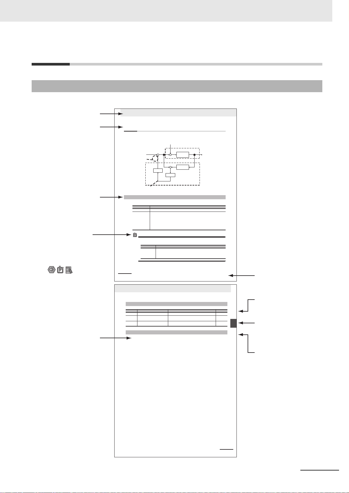
Manual Structure
11 Adjustment Functions
11-26
11-8 Disturbance Observer Function
You can use the disturbance force value estimated with the disturbance observer to lower the effect of
the disturbance force and reduce vibration.
The disturbance observer function can be used in the following situations.
Precautions for Correct UsePrecautions for Correct Use
The disturbance observer function may not work properly under the c onditions described in the
following table.
11-8-1 Operating Conditions
Conditions
Operating mode Position control Mode, speed control
Others • When Servo is ON.
• When elements other than control parameters, such as the force limit, are set correctly
and there is no trouble with the motor's normal (The setting of 3002 hex is “0”.).
• When realtime a utotuning function is disabled operation.
•
When instantaneous speed observer function is disabled (The setting of 361 0 he x bi t 0 is “0”.).
progress.
• Dis turbance obse rver operation is disabled wh en magnetic pole position estimation is in
Conditions under which the adaptive filter does not operate properly
Load condition • If there is a resonance point below the cut-off frequency estimated by the distur-
bance observer
• If a large amount of high-frequency elements is found in the disturbance force
• If the the external encoder resolution is low
Motor+load
+
−
Load model
+ −
Filter
Gain
+
+
Disturbance observer
Add to the
direction that
negates the
disturbance
Setting with
3623 hex
Set with 3624 hex
Disturbance force
Estimation value
Disturbance force
Force command
Internal force command
Motor Speed
G5 Series AC ServoDrives With Built-in EtherCAT Communications, Linear Motor Type
11-27
11 Adjustment Functions
revresbO ecnabrutsiD 8-11
noitcnuF
11
sgnitteS gniriuqeR stcejbO
2-8-11
1
Set the Function Expansion Setting (3610 hex).
Set whether to enable or disable the disturbance observer in bit 1.
0: Disabled
1: Enabled
Set the operating conditions for enabling the function in bit 2.
0: Enabled at all time
1: Enabled only when gain 1 is selected
2
Set the Disturbance Observer Filter Setting (3624 hex).
Set a small value for the Disturbance Force Compensation Gain (3623 hex). Change the value
in the Disturbance Observer Filter Setting (3624 hex) from a large value gradually to a smaller
one. The smaller the value set in the Disturbance Observer Filter Setting (3624 he x) , t he l e s s
the lag you will have during disturbance force estimation. This has advantages in effectively
controlling the influence of disturbance, but results in a large operation noise. Consider the
balance between the advantage and disadvantage when setting this value.
3
Set the Disturbance Torque Compensation Gain (3623 hex).
After you set the Disturbance Observer Filter Setting (3624 hex), increase the value of the
Disturbance Force Compensation Gain (3623 hex) from a small value to a large value. The
larger the value set on the Disturbance Torque Compensation Gain (3623 hex) is, the more
effective control over the disturbance influence can be obtained. But the larger the value is, the
larger the operation noise will be. Set this object in combination with the Disturbance Observer
Filter Setting (3624 hex) to achieve balanced settings.
11-8-2 Objects Requiring Settings
Index Name Description Reference
3610 hex Function Expansion Settings Set the bits related to the disturbance observer. page 9-44
3623 hex Disturbance Force Compensation
Gain
Set the compensation gain for disturbance force. page 9-46
3624 hex Disturbance Observer Filter Setting Set the filter time constant for disturbance force
compensation.
page 9-46
11-8-3 Operating Procedure
G5 Series AC ServoDrives With Built-in EtherCAT Communications, Linear Motor Type
Level 2 heading
Level 3 heading
Level 1 heading
Manual Name
Level 2 heading
Section Number of
Level 1 heading
Level 3 heading
Shows which section
the content of the current
page belongs to.
Shows which sub-section
the content of the current
page belongs to.
Shows which paragraph
the content of the current
page belongs to.
Note, Supplementary
Information, Reference Target
A note, supplementary
information, reference target,
etc. are provided with
difference icons.
Operation Steps
Describes
the operation steps.
Page Structure and Symbol Icons
The following page structure and symbol icons are used in this manual.
Manual Structure
G5-series Linear Motors/Servo Drives With Built-in EtherCAT Communications
Note The above page is only a sample for illustrative purposes. It is not the actual content of the manual.
3
Page 6
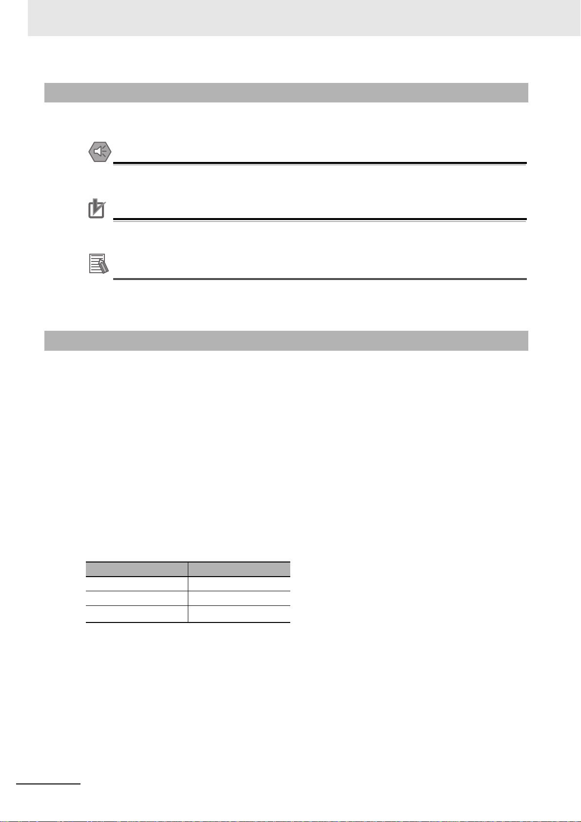
Manual Structure
Precautions for Safe Use
Precautions for Correct UsePrecautions for Correct Use
Additional Information
Special Information
Special information in this manual is classified as follows:
Precautions on what to do and what not to do to ensure safe usage of the product.
Precautions on what to do and what not to do to ensure proper operation an d performance.
Additional information to read as required.
This information is provided to increase understanding or make operation easier.
Terms and Expressions Used for the Linear Motor
In this manual, the term “Linear Motor” is defined as an OMRON product that consists of a Motor Coil
Unit (the coil on the primary side) and a Magnet Track (the magnets on the secondary side).
In addition to these components, constr u ctin g a Lin ea r Mot or syste m also requires the following parts,
which are built into a component called the “Linear Slider.”
• Motor Coil Unit (the coil on the primary side)
• Magnet Track (the magnets on the secondary side)
• External encoder
• Linear guide
• Chassis
*1 Not available from OMRON.
*1
Because a Linear Motor provides a linear movement, terms or expressions different from rotary motors
are used.
Example
Rotary Linear
Torque [N·m] Force [N]
Rotation speed [r/min] Speed [mm/s]
Inertia [kg·m
*1
*1
2
] Mass [kg]
2
However, for object names with respect to the CiA 402 Drive Profile and the terms used for the Safe
Torque OFF (STO) function, the manual uses the word “torque” for conformance with the relevant
standards.
Read “torque” as “force” when using these object names.
4
G5-series Linear Motors/Servo Drives With Built-in EtherCAT Communications
Page 7
1
10
2
11
3
12
4A
5
6
7
8
9
1
10
2
11
3
12
4A
5I
6
7
8
9
Features and System
Configuration
Operation
Models and External
Dimensions
Adjustment Functions
Specifications
Troubleshooting and
Maintenance
System Design Appendices
I
Index
EtherCAT
Communications
Basic Control Functions
Applied Functions
Safety Function
Servo Parameter Objects
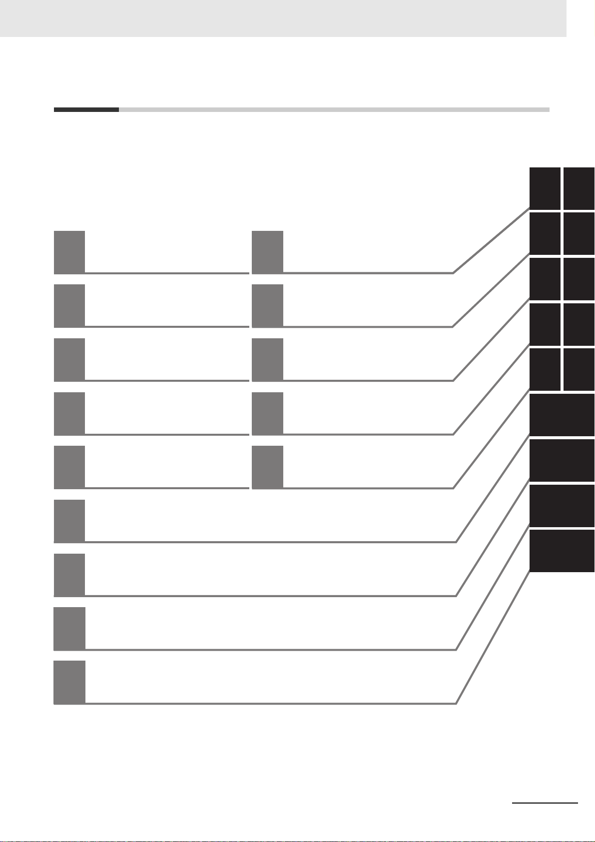
Sections in this Manual
Sections in this Manual
G5-series Linear Motors/Servo Drives With Built-in EtherCAT Communications
5
Page 8

CONTENTS
CONTENTS
Introduction ...............................................................................................................1
Manual Configuration ...............................................................................................2
Manual Structure.......................................................................................................3
Sections in this Manual ............................................................................................5
CONTENTS ................................................................................................................6
Terms and Conditions Agreement.........................................................................12
Safety Precautions..................................................................................................14
Regulations and Standards....................................................................................24
Items to Check after Unpacking.............................................................................27
Revision History......................................................................................................30
Section 1 Features and System Configuration
1-1 Outline......................................................................................................................................1-2
1-1-1 Features of G5-series Servo Drives............................................................................................1-2
1-1-2 What is EtherCAT?.....................................................................................................................1-3
1-1-3 Object Dictionary.........................................................................................................................1-3
1-2 System Configuration............. .... ... ... ....................................... ... ............................................ 1-4
1-3 Names and Functions............................................................................................................. 1-6
1-3-1 Servo Drive Part Names ...................................................................... .......................................1-6
1-3-2 Servo Drive Functions......................................................... ... ..................................... ... .............1-7
1-4 System Block Diagram................................ ... ... ....................................... ... ............................ 1-8
1-5 Unit Versions .........................................................................................................................1-12
1-5-1 Confirmation Method.................................................................................................................1-12
1-5-2 Unit Versions........................................................................................... ... ... ............................1-12
Section 2 Models and External Dimensions
2-1 Servo System Configuration..................................................................................................2-2
2-2 How to Read Model Numbers................................................................................................. 2-4
2-2-1 Servo Drive ..................................................................................................... ... .........................2-4
2-2-2 Linear Motor..................................................... ... .. ..................................... ... ..............................2-5
2-3 Model Tables............................................................................................................................ 2-7
2-3-1 Servo Drive Model Table.............................................................................................................2-7
2-3-2 Linear Motor Model Table...........................................................................................................2-7
2-3-3 Servo Drive and Linear Motor Combination Tables....................................................................2-8
2-3-4 Cable and Peripheral Device Model Tables..............................................................................2-10
2-4 External and Mounting Dimensions..................................................................................... 2-12
2-4-1 Servo Drive Dimensions.................................................................. .. ........................................2-12
2-4-2 Linear Motor Dimensions............................................... .................................... ... ... .................2-20
2-4-3 External Regeneration Resistor Dimensions ............................................................................2-27
2-4-4 Reactor Dimensions........................................................................................... ... ... .................2-28
2-4-5 Mounting Bracket Dimensions ..................................................................................................2-31
6
G5-series Linear Motors/Servo Drives With Built-in EtherCAT Communications
Page 9

CONTENTS
Section 3 Specifications
3-1 Servo Drive Specifications.....................................................................................................3-2
3-1-1 General Specifications................................................................................................................ 3-2
3-1-2 Characteristics............................................................................................................................ 3-3
3-1-3 EtherCAT Communications Specifications................................................................................. 3-5
3-1-4 EtherCAT Communications Connector Specifications (RJ45).................................................... 3-5
3-1-5 Control I/O Specifications (CN1).................................................................................................3-6
3-1-6 Control Input Circuits..................................................................................................................3-8
3-1-7 Control Input Details...................................................................... ... .......................................... 3-9
3-1-8 Control Output Circuits............................................................. ... .. ........................................... 3-11
3-1-9 Control Output Details ..............................................................................................................3-12
3-1-10 External Encoder Specifications...............................................................................................3-16
3-1-11 External Encoder Connector Specifications (CN4)...................................................................3-17
3-1-12 Analog Monitor Connector Specifications (CN5) ................................................................... ...3-21
3-1-13 USB Connector Specifications (CN7).......................................................................................3-22
3-1-14 Safety Connector Specifications (CN8)....................................................................................3-22
3-2 Overload Characteristics (Electronic Thermal Function).................................................. 3-25
3-3 Linear Motor Specifications ................................................................................................. 3-28
3-3-1 General Specifications of Iron-core Linear Motors ................................................................... 3-28
3-3-2 Performance Specifications of Iron-core Linear Motors............................................................3-29
3-3-3 Iron-core Linear Motor Speed - Force Characteristics.............................................................. 3-32
3-3-4 Temperature Sensor Specifications of Iron-core Linear Motors............................................... 3-35
3-3-5 General Specifications of Ironless Linear Motors..................................................................... 3-36
3-3-6 Performance Specifications of Ironless Linear Motors ............................................................. 3-36
3-3-7 Ironless Linear Motor Speed - Force Characteristics ............................................................... 3-39
3-3-8 Temperature Sensor Specifications of Ironless Linear Motors.................................................3-44
3-3-9 Cable Specifications................................................................................................................. 3-45
3-4 Cable and Connector Specifications................................................................................... 3-46
3-4-1 Resistance to Bending of Robot Cable........................................ ............................... .. ............ 3-46
3-4-2 External Encoder Cable Specifications..................................................................................... 3-47
3-4-3 Connector Specifications..........................................................................................................3-48
3-4-4 EtherCAT Communications Cable Specifications..................................................................... 3-49
3-4-5 Analog Monitor Cable Specifications........................................................................................3-52
3-4-6 Control Cable Specifications............................ .................................... ... .................................. 3-53
3-5 External Regeneration Resistor Specifications.................................................................. 3-58
3-6 Reactor Specifications.......................................................................................................... 3-59
Section 4 System Design
4-1 Installation Conditions............................................................................................................ 4-2
4-1-1 Installation Conditions.................................................................................................................4-2
4-1-2 Iron-core Linear Motor Installation Conditions............................................................................ 4-4
4-1-3 Ironless Linear Motor Installation Conditions............................................................................ 4-10
4-2 Wiring ..................................................................................................................................... 4-14
4-2-1 Peripheral Equipment Connection Examples ........................................................................... 4-14
4-2-2 Main Circuit and Linear Motor Connections........................... ..................................... .. ............ 4-18
4-2-3 Terminal Block Wire Sizes........................................................................................................ 4-22
4-2-4 Terminal Block Wiring Procedure.............................................................................................4-24
4-3 Wiring Conforming to EMC Directives ................................................................................ 4-26
4-3-1 100-VAC and 200-VAC Input Servo Drive Models...................................................................4-26
4-3-2 400-VAC Input Servo Drive Models..........................................................................................4-27
4-4 Noise Reduction.................................................................................................................... 4-29
4-4-1 Wiring Method........................................................................................................................... 4-29
4-4-2 Selecting Connection Components ..........................................................................................4-33
G5-series Linear Motors/Servo Drives With Built-in EtherCAT Communications
7
Page 10

CONTENTS
4-5 Regenerative Energy Absorption......................................................................................... 4-47
4-5-1 Calculating the Regenerative Energy........................................................................................4-47
4-5-2 Servo Drive Regeneration Absorption Capacity........................................................................4-49
4-5-3 Regenerative Energy Absorption with an External Regeneration Resistor ...............................4-50
4-5-4 Connecting an External Regeneration Resistor........................................................................4-51
Section 5 EtherCAT Communications
5-1 Display Area and Settings......................................................................................................5-2
5-1-1 Node Address Setting.................................................................................................................5-2
5-1-2 Status Indicators .........................................................................................................................5-3
5-2 Structure of the CAN Application Protocol over EtherCAT................................................. 5-4
5-3 EtherCAT State Machine......................................................................................................... 5-5
5-4 Process Data Objects (PDOs) ................................................................................................ 5-6
5-4-1 PDO Mapping Settings................................................................................................................5-6
5-4-2 Sync Manager PDO Assignment Settings ..................................................................................5-7
5-4-3 Fixed PDO Mapping.......................................................... .. ..................................... ... ... .............5-7
5-4-4 Variable PDO Mapping ..................................................................... ..........................................5-9
5-4-5 Multiple PDO Mapping..............................................................................................................5-10
5-5 Service Data Objects (SDOs)................................................................................................ 5-12
5-6 Synchronization with Distributed Clocks............................................................................ 5-13
5-7 Emergency Messages...........................................................................................................5-14
5-8 Sysmac Device Features ...................................................................................................... 5-15
Section 6 Basic Control Functions
6-1 Cyclic Synchronous Position Mode.......................................................................................6-2
6-1-1 Related Objects...........................................................................................................................6-3
6-1-2 Block Diagram for Position Control Mode...................................................................................6-4
6-2 Cyclic Synchronous Velocity Mode.......................................................................................6-5
6-2-1 Related Objects...........................................................................................................................6-6
6-2-2 Objects Requiring Settings..........................................................................................................6-6
6-2-3 Related Functions.......................................................................................................................6-6
6-2-4 Block Diagram for Speed Control Mode...................................................................................... 6-7
6-3 Cyclic Synchronous Torque Mode......................................................................................... 6-8
6-3-1 Related Objects...........................................................................................................................6-9
6-3-2 Objects Requiring Settings..........................................................................................................6-9
6-3-3 Related Functions.....................................................................................................................6-10
6-3-4 Block Diagram for Force Control Mode.....................................................................................6-10
6-4 Profile Position Mode . .... ...................................... .... ...................................... .... ... ................6-11
6-4-1 Related Objects.........................................................................................................................6-12
6-4-2 Description of Function.............................................................................................................6-13
6-4-3 Controlword (6040 hex) in Profile Position Mode................................................................ ... ...6-14
6-4-4 Statusword (6041 hex) in Profile Position Mode.......................................................................6-14
6-5 Homing Mode.........................................................................................................................6-15
6-6 Connecting with OMRON Controllers.................................................................................. 6-16
Section 7 Applied Functions
7-1 Sequence I/O Signals.............................................................................................................. 7-2
7-1-1 Input Signals ...............................................................................................................................7-2
7-1-2 Output Signals.............................................................................................................................7-5
7-2 Positive and Negative Drive Prohibition Functions....... .... ... ... ... ... .... ... ... ... .... ... ... ... ....... ... .. 7-8
8
G5-series Linear Motors/Servo Drives With Built-in EtherCAT Communications
Page 11

CONTENTS
7-3 Overrun Protection................................................................................................................ 7-11
7-3-1 Operating Conditions................................................................................................................ 7-11
7-3-2 Objects Requiring Settings....................................................................................................... 7-11
7-3-3 Operation Example............................................... ... .................................... ... .......................... 7-12
7-4 Backlash Compensation....................................................................................................... 7-13
7-5 Brake Interlock....................................................................................................................... 7-15
7-5-1 Objects Requiring Settings....................................................................................................... 7-15
7-5-2 Operation Timing.......................................... .................................... ... ... ..................................7-16
7-6 Electronic Gear Function...................................................................................................... 7-20
7-6-1 Objects Requiring Settings....................................................................................................... 7-20
7-6-2 Operation Example............................................... ... .................................... ... .......................... 7-21
7-7 Force Limit Switching........................................................................................................... 7-22
7-7-1 Operating Conditions................................................................................................................ 7-22
7-7-2 Objects Requiring Settings....................................................................................................... 7-22
7-8 Soft Start ............................................... .... ... ... ... ....................................... ... .......................... 7-24
7-8-1 Objects Requiring Settings....................................................................................................... 7-24
7-8-2 Soft Start Acceleration or Deceleration Time.......................................... ... .. .............................7-24
7-8-3 S-curve Acceleration or Deceleration Time .............................................................................. 7-25
7-9 Gain Switching Function ......................................................................................................7-26
7-9-1 Objects Requiring Settings....................................................................................................... 7-26
7-9-2 Gain Switching Based on the Control Mode.............................................................................7-28
7-9-3 Diagrams of Gain Switching Setting. ........................................................................................7-31
7-9-4 Position Gain Switching Time (3119 hex).................................................................................7-36
7-10 Gain Switching 3 Function ...................................................................................................7-37
7-10-1 Operating Conditions................................................................................................................ 7-37
7-10-2 Objects Requiring Settings....................................................................................................... 7-37
7-10-3 Operation Example.................................................. .................................... ... .......................... 7-37
7-11 Touch Probe Function (Latch Function) ....................................................... ... ... ... ... .... ... ... 7-39
7-11-1 Objects Requiring Settings....................................................................................................... 7-39
7-11-2 Trigger Signal Settings.............................................................................................................7-39
7-11-3 Operation Sequences............................................................................................................... 7-40
Section 8 Safety Function
8-1 Safe Torque OFF Function ................................................................................ ... ... ...............8-2
8-1-1 Safety Input Signals......................................................... ... ..................................... ... ................ 8-3
8-1-2 External Device Monitor (EDM) Output Signal ...........................................................................8-4
8-1-3 Relationship Between Safety Input Signals and EDM Output Signal......................................... 8-4
8-2 Operation Example......... ... ... ....................................... ... ....................................... ... ... ............ 8-5
8-3 Connection Example............................................................................................................... 8-7
Section 9 Servo Parameter Objects
9-1 Basic Settings.......................................................................................................................... 9-2
9-2 Gain Settings ........................................................................................................................... 9-7
9-3 Vibration Suppression Settings........................................................................................... 9-18
9-4 Analog Control Objects ........................................................................................................9-25
9-5 Interface Monitor Settings.................................................................................................... 9-30
9-6 Extended Objects..................... ... ... ... ....................................... ... .......................................... 9-41
9-7 Special Objects...................................................................................................................... 9-47
9-8 Linear Motor Objects............................................................................. ... ............................. 9-61
G5-series Linear Motors/Servo Drives With Built-in EtherCAT Communications
9
Page 12

CONTENTS
Section 10 Operation
10-1 Operational Procedure.......................................................................................................... 10-2
10-2 Preparing for Operation........................................................................................................10-4
10-2-1 Items to Check Before Turning ON the Power Supply..............................................................10-4
10-2-2 Turning ON the Power Supply..................................................................................................10-6
10-2-3 Checking the Displays................................ ..................................... .. ........................................10-6
10-2-4 Preparing the Linear Motor for Operation .................................................................................10-8
10-3 Linear Motor Setup.............................................................................................................. 10-13
10-3-1 Outline of Linear Motor Setup.................................................................................................10-14
10-3-2 Operation from the CX-Drive...................................................................................................10-14
10-3-3 Connection from the CX-Drive via Network ............................................................................10-23
10-3-4 Connection from the Sysmac Studio via Network...................................................................10-25
10-4 Trial Operation..................................................................................................................... 10-27
10-4-1 Preparations for Trial Operation..............................................................................................10-27
10-4-2 Trial Operation via USB Communications from the CX-Drive.................................................10-28
10-4-3 Setup via Network............................................... .. ..................................... ... ............... ...........10-28
Section 11 Adjustment Functions
11-1 Analog Monitor .................................. ... ... .... ... ... ... .... ...................................... .... ...................11-2
11-2 Gain Adjustment.................................................................................................................... 11-5
11-2-1 Purpose of the Gain Adjustment...............................................................................................11-5
11-2-2 Gain Adjustment Methods.........................................................................................................11-5
11-2-3 Gain Adjustment Procedure.............................................. .................................... ... ... ..............11-6
11-3 Realtime Autotuning .............................................................................................................11-7
11-3-1 Operating Conditions ................................................................................................................11-8
11-3-2 Objects Requiring Settings........................................................................................................11-8
11-3-3 Setting Realtime Autotuning......................................................................................................11-9
11-3-4 Setting Machine Rigidity..........................................................................................................11-10
11-3-5 Objects to Be Updated................................................ ... .................................... ... ... ...............11-12
11-4 Manual Tuning .....................................................................................................................11-15
11-4-1 Preparation for Manual Tuning................................................................................................11-15
11-4-2 Position Control Mode Adjustment..........................................................................................11-16
11-5 Damping Control ............ ..................................................................................................... 11-17
11-5-1 Operating Conditions ..............................................................................................................11-17
11-5-2 Objects Requiring Settings......................................................................................................11-18
11-5-3 Operating Procedure...............................................................................................................11-19
11-6 Adaptive Filter .... ... ....................................... ... ....................................... ... ... ........................ 11-21
11-6-1 Operating Conditions ..............................................................................................................11-22
11-6-2 Objects Requiring Settings......................................................................................................11-22
11-6-3 Objects to Be Set Automatically..............................................................................................11-23
11-6-4 Operating Procedure...............................................................................................................11-23
11-7 Notch Filters......................................................................................................................... 11-24
11-7-1 Objects Requiring Settings......................................................................................................11-25
11-7-2 Notch Filter Width and Depth............................................ .. ..................................... ... ............11-26
11-8 Disturbance Observer Function......................................................................................... 11-28
11-8-1 Operating Conditions ..............................................................................................................11-28
11-8-2 Objects Requiring Settings......................................................................................................11-29
11-8-3 Operating Procedure...............................................................................................................11-29
11-9 Friction Force Compensation Function.............................................................................11-30
11-9-1 Operating Conditions ..............................................................................................................11-30
11-9-2 Objects Requiring Settings......................................................................................................11-30
11-9-3 Operating Procedure...............................................................................................................11-31
10
G5-series Linear Motors/Servo Drives With Built-in EtherCAT Communications
Page 13

CONTENTS
11-10Feed-forward Function...................... ... .... ... ... ... .... ...... ... .... ... ... ... ... .... ... ... ... .... ... ... ... ... .... . ... 11-32
11-10-1 Objects Requiring Settings ..................................................................................................... 11-32
11-10-2 Operating Procedure .............................. ... .................................... ... ...................................... 11-33
11-11Instantaneous Speed Observer Function ......................................................................... 11-35
11-11-1 Operating Conditions..............................................................................................................11-35
11-11-2 Objects Requiring Settings ..................................................................................................... 11-36
11-11-3 Operating Procedure .............................. ... .................................... ... ...................................... 11-36
Section 12 Troubleshooting and Maintenance
12-1 Actions for Problems .................................................. ... .... ... ... ....................................... ...... 12-2
12-1-1 Preliminary Checks When a Problem Occurs...........................................................................12-2
12-1-2 Precautions When a Problem Occurs.......................................................................................12-3
12-1-3 Replacing the Linear Motor or Servo Drive...............................................................................12-3
12-2 Warnings ................................................................................................................................ 12-5
12-2-1 Related Objects........................................................................................................................ 12-5
12-2-2 Warning List............................................................................................... .. ............................. 12-6
12-3 Errors...................................................................................................................................... 12-9
12-3-1 Error List................................................................................................................................... 12-9
12-3-2 Immediate Stop Operation at Errors.......................................................................................12-11
12-4 Troubleshooting .................................................................................................................. 12-13
12-4-1 Troubleshooting with Error Displays.......................................................................................12-13
12-4-2 Troubleshooting with the AL Status Code.............................................................................. 12-27
12-4-3 Troubleshooting Using the Operation State............................................................................ 12-28
12-5 Periodic Maintenance.......................................................................................................... 12-35
12-5-1 Linear Slider Life Expectancy................................................................................................. 12-35
12-5-2 Servo Drive Life Expectancy................................................................................................... 12-36
Appendices
A-1 CiA402 Drive Profile ................................................. ... ... .... ... ... ... ............................................A-2
A-1-1 Controlling the State Machine of the Servo Drive.......................................................................A-2
A-1-2 Modes of Operation..................................................................... .. .............................................A-4
A-1-3 Communications Cycles and Corresponding Modes of Operation........................................ ... ..A-5
A-1-4 Modes of Operation and Applied Functions................................................................................A-6
A-1-5 Changing the Mode of Operation................................................................................................A-7
A-1-6 Homing Mode Specifications....................................................................................................A-15
A-1-7 Object Dictionary......................................................................................................................A-22
A-1-8 Communication Objects............................................................................................................A-25
A-1-9 PDO Mapping Objects..............................................................................................................A-31
A-1-10 Sync Manager Communication Objects ...................................................................................A-44
A-1-11 Manufacturer Specific Objects..................................................................................................A-49
A-1-12 Servo Drive Profile Objects.......................................................................................................A-55
A-2 Object List..............................................................................................................................A-77
A-3 Sysmac Error Status Codes .................................................................................................A-95
A-3-1 Error Table................................................................................................................................A-95
A-3-2 Error Description.....................................................................................................................A-109
A-4 Response Time in EtherCAT Process Data Communications ........................................A-167
A-4-1 Input Response Time..............................................................................................................A-167
A-4-2 Output Response Time............................................ ... ... .................................... ... ..................A-168
A-5 EtherCAT Terminology .......................................................................................................A-169
Index
G5-series Linear Motors/Servo Drives With Built-in EtherCAT Communications
11
Page 14

Terms and Conditions Agreement
Terms and Conditions Agreement
Warranty, Limitations of Liability
Warranties
z Exclusive Warranty
Omron’s exclusive warranty is that the Products will be free from defects in materials and
workmanship for a period of twelve months from the date of sale by Omron (or such other period
expressed in writing by Omron). Omron disclaims all other warranties, express or implied.
z Limitations
OMRON MAKES NO WARRANTY OR REPRESENTATION, EXPRESS OR IMPLIED, ABOUT
NON-INFRINGEMENT, MERCHANTABILITY OR FITNESS FOR A PARTICULAR PURPOSE OF
THE PRODUCTS. BUYER ACKNOWLEDGES THAT IT ALONE HAS DETERMINED THAT THE
PRODUCTS WILL SUITABLY MEET THE REQUIREMENTS OF THEIR INTENDED USE.
Omron further disclaims all warranties and responsibility of any type for claims or expenses based
on infringement by the Products or otherwise of any intellectual property right.
z Buyer Remedy
Omron’s sole obligation hereunder shall be, at Omron’s electi on, to (i) replace (in the form origin ally
shipped with Buyer responsible for labor charges for removal or replacement thereof) the
non-complying Product, (ii) repair the non-complying Product, or (iii) repay or credit Buyer an
amount equal to the purchase price of the non-complying Product; provided that in no event shall
Omron be responsible for warranty, repair, indemnity or any other claims or expenses rega rding the
Products unless Omron’s analysis confirms that the Products were properly handled, stored,
installed and maintained and not subject to contamination, abuse, misuse or inappropriate
modification. Return of any Products by Buyer must be approved in writing by Omron before
shipment. Omron Companies shall not be liable for the suitability or unsuitability or the results from
the use of Products in combination with any electrical or electronic components, circuits, system
assemblies or any other materials or substances or environments. Any advice, recommendations or
information given orally or in writing, are not to be construed as an amendment or addition to the
above warranty.
See http://www.omron.com/global/ or contact your Omron representative for published information.
Limitation on Liability; Etc
OMRON COMPANIES SHALL NOT BE LIABLE FOR SPECIAL, INDIRECT, INCIDENTAL, OR
CONSEQUENTIAL DAMAGES, LOSS OF PROFITS OR PRODUCTION OR COMMERCIAL LOSS IN
ANY WAY CONNECTED WITH THE PRODUCTS, WHETHER SUCH CLAIM IS BASED IN
CONTRACT, WARRANTY, NEGLIGENCE OR STRICT LIABILITY.
Further, in no event shall liability of Omron Companies exceed the individual price of the Product on
which liability is asserted.
12
G5-series Linear Motors/Servo Drives With Built-in EtherCAT Communications
Page 15

Application Considerations
Suitability of Use
Omron Companies shall not be responsible for conformity with any standards, codes or regulations
which apply to the combination of the Product in the Buyer’s application or use of the Product. At
Buyer’s request, Omron will provide applicable third party certification documents identifying ratings
and limitations of use which apply to the Product. This information by itself is not sufficient for a
complete determination of the suitability of the Product in combination with the end product, machine,
system, or other application or use. Buyer shall be solely responsible for determining appropriateness
of the particular Product with respect to Buyer’s application, product or system. Buyer shall take
application responsibility in all cases.
NEVER USE THE PRODUCT FOR AN APPLICATION INVOLVING SERIOUS RISK TO LIFE OR
PROPERTY WITHOUT ENSURING THAT THE SYSTEM AS A WHOLE HAS BEEN DESIGNED TO
ADDRESS THE RISKS, AND THAT THE OMRON PRODUCT(S) IS PROPERLY RATED AND
INSTALLED FOR THE INTENDED USE WITHIN THE OVERALL EQUIPMENT OR SYSTEM.
Terms and Conditions Agreement
Programmable Products
Omron Companies shall not be responsible for the user’s programming of a programmable Product,
or any consequence thereof.
Disclaimers
Performance Data
Data presented in Omron Company websites, catalogs and other materials is provided as a guide for
the user in determining suitability and does not constitute a warranty. It may represent the result of
Omron’s test conditions, and the user must correlate it to actual application requirements. Actual
performance is subject to the Omron’s Warranty and Limitations of Liability.
Change in Specifications
Product specifications and accessories may be changed at any time b ased on improve ments and other
reasons. It is our practice to change part numbers when published ratings or features are changed, or
when significant construction changes are made. However, some specifications of the Product may be
changed without any notice. When in doubt, special part numbers may be assigned to fix or establish
key specifications for your application. Please consult with your Omron’s representative at any time to
confirm actual specifications of purchased Product.
Errors and Omissions
Information presented by Omron Companies has been checked and is believed to be accurate;
however, no responsibility is assumed for clerical, typographical or proofreading errors or omissions.
G5-series Linear Motors/Servo Drives With Built-in EtherCAT Communications
13
Page 16
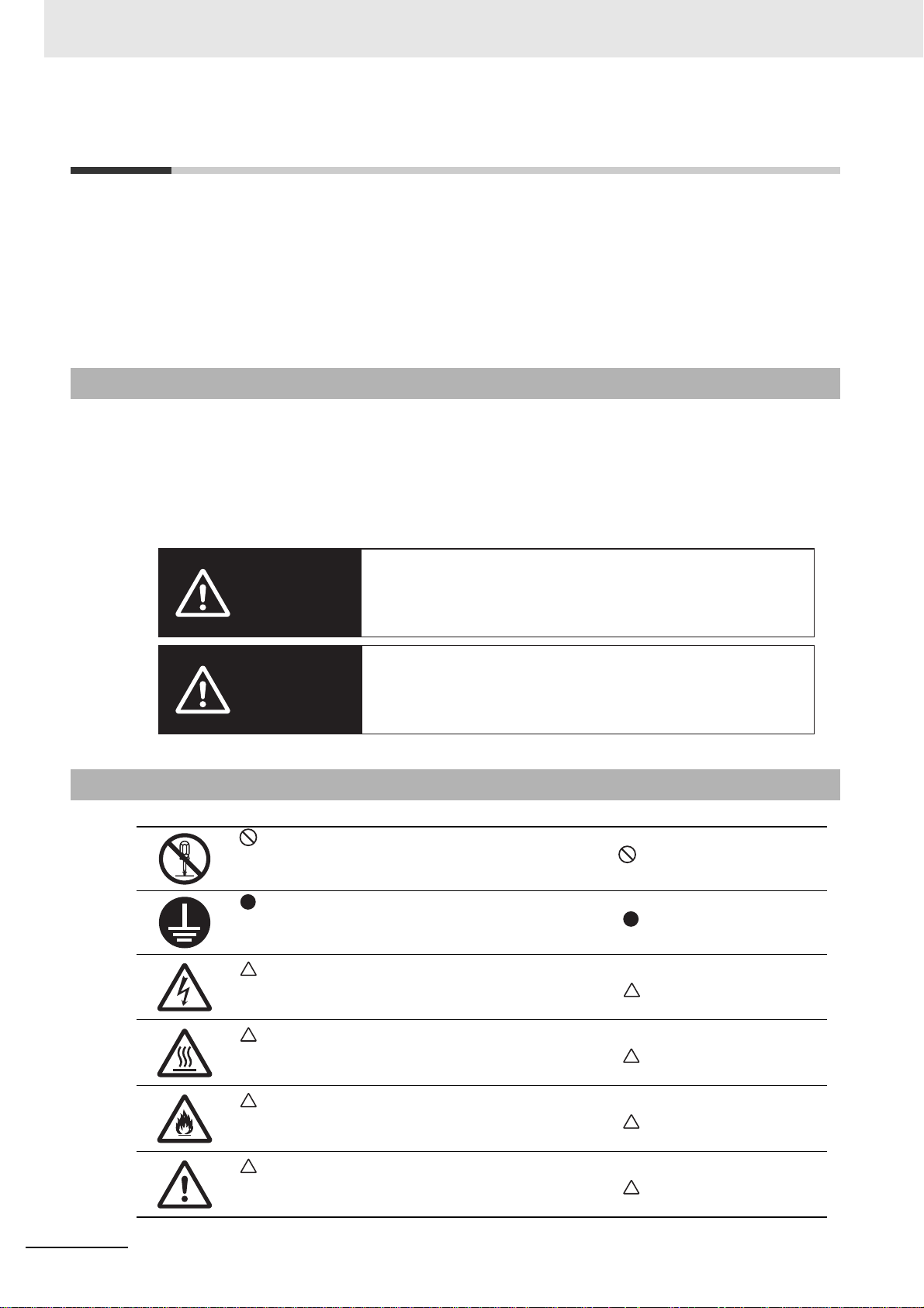
Safety Precautions
Indicates a potentially hazardous situation which,
if not avoided, may result in minor or moderate
injury, or property damage.
Indicates a potentially hazardous situation which, if
not avoided, could result in death or serious injury.
Additionally, there may be severe property damage.
DANGER
Caution
Safety Precautions
To ensure that the G5-series Servo Drive and Servomotor as well as peripheral equipment are used safely
and correctly, be sure to read this Safety Precautions section and the main text before using the product.
Learn all items you should know before use, regarding the equipment as well as the required safety
information and precautions.
Make an arrangement so that this manual also gets to the end user of this product.
After reading this manual, keep it in a convenient place so that it can be referenced at any time.
Definition of Precautionary Information
The following notation is used in this manual to provide precautions required to ensure safe usage of
G5-series Servo Drives and Servomotors.
The safety precautions that are provided are extremely important to safety. Always read and heed the
information provided in all safety precautions.
The display of precautions used in this manual and their meanings are explained below.
Explanation of Symbols
This symbol indicates a prohibited item.
The specific instruction is indicated using an illustration inside and text.
The symbol shown to the left indicates “disassembly prohibited.”
This symbol indicates a compulsory item.
The specific instruction is indicated using an illustration inside and text.
The symbol shown to the left indicates “grounding required.”
14
This symbol indicates danger and caution.
The specific instruction is indicated using an illustration inside and text.
The symbol shown to the left indicates “beware of electric shock.”
This symbol indicates danger and caution.
The specific instruction is indicated using an illustration inside
The symbol shown to the left indicates the “risk of hot surface.”
This symbol indicates danger and caution.
The specific instruction is indicated using an illustration inside and text.
The symbol shown to the left indicates the “risk of fire.”
This symbol indicates danger and caution.
The specific instruction is indicated using an illustration inside
The symbol shown to the left indicates a “general precaution.”
G5-series Linear Motors/Servo Drives With Built-in EtherCAT Communications
and text.
and text.
Page 17
Precautions for Safe Use of This Product
DANGER
• Illustrations contained in this manual sometimes depict conditions without covers and safety shields
for the purpose of showing the details.
When using this product, be sure to install the covers and shields as specified and use the product
according to this manual.
• If the product has been stored for an extended period of time, contact your OMRON sales
representative.
Be sure to ground the frame ground terminals and ground wires for the Servo Drive and
Motor with 100 VAC or 200 VAC to 100 Ω or less, and for the Servo Drive and Motor with
400 VAC to 10 Ω or less.
Electric shock may result.
Never touch the parts inside the Servo Drive or the cable ends of the Motor Coil Unit.
Electric shock may result.
Safety Precautions
Do not remove the front cover, terminal covers, cables, or optional items while the power is
being supplied.
Doing so may result in electric shock.
Installation, operation and maintenance or inspection by unauthorized personnel is
prohibited.
Electric shock or injury may result.
Before carrying out wiring or inspection, turn OFF the main circuit power and wait for at
least 15 minutes.
Electric shock may result.
Install the Servo Drive and Motor before wiring.
Improper grounding may result in electrical shock.
Do not damage, pull, or put excessive stress or heavy objects on the cables.
Doing so may cause electric shock, malfunction, or burning.
Do not use the cable when it is laying in oil or water.
Electric shock, injury, or fire may result.
Do not perform wiring or any operation with wet hands.
Electric shock, injury, or fire may result.
Do not touch the Servo Drive radiator, Regeneration Resistor, or Motor while the power is
supplied or for a while after the power is turned OFF becuse they get hot.
Fire or a burn injury may result.
Use the Motor and Servo Drive in a specified combination.
Fire or equipment damage may result.
Never connect a power supply directly to the Motor.
Fire or failure may result.
G5-series Linear Motors/Servo Drives With Built-in EtherCAT Communications
15
Page 18
Safety Precautions
Do not enter the operating area during operation.
Injury may result.
Never modify the Servo Drive.
Injury or equipment damage may result.
Install a stopping device on the machine to ensure safety.
* The holding brake is not a stopping device to ensure safety.
Injury may result.
Install an immediate stop device externally to the machine so that the operation can be
stopped and the power supply is cut off immediately.
Injury may result.
When the power is restored after a momentary power interruption, the machine may restart
suddenly. Never come close to the machine when restoring power.
* Implement measures to ensure safety of people nearby even when the machine is
restarted.
Injury may result.
After an earthquake, be sure to conduct safety checks.
Electric shock, injury, or fire may result.
Never drive the Motor using an external drive source.
Fire may result.
Do not place flammable materials near the Motor, Servo Drive, or Regeneration Resistor.
Fire may result.
Install the Motor, Servo Drive, and Regeneration Resistor on non-flammable materials such
as metals.
Fire may result.
When constructing a system that includes safety functions, be sure you understand the
relevant safety standards and all related information in user documentation, and design the
system to comply with the standards.
Not doing so may result in injury or equipment damage.
If the motor is not controlled, it may not be possible to maintain the stop.
To ensure safety, install a stop device. Risk of equipment damage and human injury.
Do not handle objects made of magnetic materials ne ar the Linear Motor. Use nonmagnetic
tools when performing installation or other work on the Linear Moto r.
The objects may be attracted by the magnetic field of the Linear Motor and you may be
caught between the motor parts, resulting in injury.
People using a pacemaker or other electronic medical device must stay away from the
linear motor.
A powerful magnetic field is generated by the stator and powered needle.
This may cause malfunctioning of electronic devices.
When shipping or transporting the Magnet Track, be sure to display that the content is a
strong magnetic product.
Medical electronics such as cardiac pacemakers may malfunction or injury may result.
Do not put the product into the fire.
Burst or gas may occur and injury may result.
16
G5-series Linear Motors/Servo Drives With Built-in EtherCAT Communications
Page 19
Safety Precautions
Caution
Do not store or install the Servo Drive in the following locations:
• Location subject to direct sunlight
• Location where the ambient temperature exceeds the specified level
• Location where the relative humidity exceeds the specified level
• Location subject to condensation due to rapid temperature changes
• Location subject to corrosive or flammable gases
• Location subject to high levels of dust, salt content, or iron dust
• Location subject to splashes of water, oil, chemicals, etc.
• Location where the Servo Drive may receive vib ration or impact directly
Installing or storing the Servo Drive in these locations may result in fire, electric shock, or
equipment damage.
The magnetic attraction force always affects between the Motor Coil Unit and Magnet Track
even when the power supply is turned OFF. Design a machine which supports the
magnetic attraction force and provides enough rigidity to maintain the accuracy.
Malfunction or failure may result.
Design a machine with consideration of the magnetic attraction force.
Malfunction or failure may result.
Do not hit the Motor Coil Unit against the stopper. Design the configuration so that the table
mounted on the Motor Coil Unit hits against the stopper.
Equipment damage may result.
Do not apply strong impact on the product.
Failure may result.
Prevent adhesion of foreign objects to the product.
Malfunction may result.
You cannot use the Linear Motor because its magnetic pole cannot be detected in an
unbalanced load such as vertical axis.
If the magnetic pole cannot be detected, an error may occur and the Linear Motor may be in
the free-run status.
Injury or equipment damage may result.
The protective structure of the Linear Motor is IP00. Take necessary measures to prevent
dust, oil, etc.
Failure may result.
Ensure that the Linear Slider has a sufficient rigidity.
Equipment damage or malfunction may result.
Provide appropriate safety measures to prevent crashes, etc. if you design a system which
cooperates multiple motor coil units such as multi-head or tandem.
Equipment damage may result.
Do not bring electronic devices, magnetic recording media, or other articles that may be
affected by magnetism (clocks, computers, measuring instruments, magnetic cards, IC
cards, etc.) near the linear motor.
This may cause malfunctioning or equipment damage.
G5-series Linear Motors/Servo Drives With Built-in EtherCAT Communications
17
Page 20
Safety Precautions
Storage and Transportation
When transporting the Motor Coil Unit, do not hold the cable.
Injury or equipment damage may result.
When transporting the Magnet Track, do not hold the cover to protect the magnet.
Injury or equipment damage may result.
Do not overload the product. (Follow the instructions on the product label.)
Injury or failure may result.
Be sure to store the product as packed in the same packing as delivered.
Injury or equipment damage may result.
Caution
When transporting or storing the magnet track, pack the product in the same condition as
delivered or cover the magnetic side by 30 mm or more thick material such as high density
plastics. (Be sure to provide more than 60 mm of thickness.)
Equipment damage may result.
The magnetic body (Motor Coil Unit, other Magnet Track or tools) generates attractive force
by Magnet Track. Be careful about the ambient environment when and after disassembling
the Linear Motor, and handling the Magnet Track.
Injury such as getting one’s hand caught in the Linear Motor or equipment damage may
result.
When lifting a 15 kW or higher Servo Drive du ring moving or installation, always have two
people lift the product by grasping a metal part.
Do not grasp a plastic part.
Injury or failure may result.
18
G5-series Linear Motors/Servo Drives With Built-in EtherCAT Communications
Page 21
Installation and Wiring
Caution
Provide the specified clearance between the Servo Drive and the inner surface of the
control panel or other equipment.
Fire or failure may result.
Use crimp terminals to wire screw type terminal blocks. Do not connect bare stranded wires
directly to terminals blocks.
Fire may result.
Provide safety measures, such as a breaker, to protect against short circuiting of external
wiring.
Fire may result.
Do not step on the Servo Drive or place heavy articles on it.
Injury may result.
Safety Precautions
Be sure to observe the mounting direction.
Failure may result.
Wire the cables correctly and securely.
Runaway motor, injury, or failure may result.
Tighten the mounting screws, terminal block screws, and cable screws for the product to
the specified torque.
Failure may result.
Use non-magnetic mounting screws. Note also that the depth of any mounted screw is less
than the effective thread depth.
Equipment damage may result.
Be sure to wire the motor coil unit cable fixedly.
Equipment damage may result.
For wiring between the Motor Coil Unit cable and the Servo Drive, use a robot cable.
Equipment damage may result.
Be sure to securely fix the Linear Motor to the machine.
The Linear Motor may come off during operation and equipment damage may result.
When installing the Linear Motor, match the center of gravity of the motor coil unit and load.
Malfunction or equipment damage may result by the increase of the running loa d.
Install linear guides with great caution to comply with the gap specification of the motor coil
unit and magnet track. (If the gap is small, the running load by the friction will increase in
proportion to the magnetic attraction force.)
Malfunction may result.
Do not allow foreign objects to enter between the Motor Coil Unit and Magnet Track.
Equipment damage or malfunction may result.
G5-series Linear Motors/Servo Drives With Built-in EtherCAT Communications
19
Page 22
Safety Precautions
Set a parameter to operate the Motor and external encoder in the same direction.
Malfunction or equipment damage may result.
When installing more than one Magnet Track, set the mounting screw accumulative pitch
tolerance within ± 0.2 mm.
Malfunction may result.
Use the specified screws for the tap holes of Motor Coil Unit. The tap holes are used to
install the Motor Coil Unit.
Equipment damage may result.
Use all tap holes of Motor Coil Unit and threaded holes of Magnet Track to install the Linear
Motor.
Equipment damage may result.
Always use the power supply voltage specified in the User’s Manual.
An incorrect voltage may result in malfunction or burning.
Take appropriate measures to ensure that the specified power with the rated voltage is
supplied.
Be particularly careful in locations where the power supply is unstable.
An incorrect power supply may result in failure.
Connect the Servo Drive to the Motor without a contactor, etc.
Malfunction or equipment damage may result.
Take appropriate and sufficient countermeasures to provide shielding when installing
systems in the following locations.
Not doing so may result in failure.
• Locati ons subject to static electricity or other forms of noise.
• Locati ons subject to strong electromagnetic fields and magnetic fields.
• Locati ons subject to possible exposure to radioactivity.
• Locati ons close to power supplies.
Do not use the Linear Motor in the location sub j ect to magnetic powders such as iron
filings.
They may adhere to the Linear Motor and failure may result.
Connect an emergency stop (immediate stop) relay in series with the brake control relay.
Injury or failure may result.
20
G5-series Linear Motors/Servo Drives With Built-in EtherCAT Communications
Page 23
Operation and Adjustment
Caution
If the Servo Drive fails, cut off the power supply to the Servo Drive.
Fire may result.
Do not block the intake or exhaust openings.
Do not allow foreign objects to enter the Servo Drive.
Fire may result.
Conduct a test operation after confirming that the equipment is not affected.
Equipment damage may result.
Check any newly set parameters and software switch settings for proper execution before
actually using them.
Not doing so may result in equipment damage.
Never adjust or set parameters to extreme values, because it will make the operation
unstable.
Injury may result.
Separate the Motor from the mechanical system and check its operation before installing
the Motor to the machine.
Injury may result.
If the magnetic body is near the Linear Motor, the cogging will occur and affect the
performance.
Malfunction or equipment damage may result.
If an error occurs, remove the cause of the error and ensure safety, and then reset the
alarm and restart the operation.
Injury may result.
Do not operate the Motor connected to an excessive load mass.
Failure may result.
Safety Precautions
Do not turn ON and OFF the main Servo Drive power supply frequently.
Failure may result.
Install equipment to prevent crash and reduce shock.
Crash against the stroke edge may occur depending on stopping distance and equipment
damage may result.
If a problem occurs in serial communications during a test operation, you have no means to
stop the Motor.
Install external hardware to ensure that the Motor can be stopped at any time.
Before transferring parameters or data from the CX-Drive and Sysmac Studio to any other
node, check the safety around the target node.
Injury may result.
Check the axis (shaft) number before operating with the CX-Drive and Sysmac Studio.
G5-series Linear Motors/Servo Drives With Built-in EtherCAT Communications
21
Page 24
Safety Precautions
Maintenance and Inspection
Do not attempt to disassemble, repair, or modify the Servomotor or Servo Drive.
Any attempt to do so may result in electric shock or other injury.
After replacing the Servo Drive, transfer to the new Servo Drive all data needed to resume
operation, before restarting operation.
Equipment damage may result.
Turn OFF the power supply when not using the Servomotor or Servo Drive for a long period
of time.
Not doing so may result in injury or malfunction.
Design the system to stop for at least ten minutes after the dynamic brake operates.
If it is used under more conditions, the dynamic brake may break and the brake may not
operate.
Caution
22
G5-series Linear Motors/Servo Drives With Built-in EtherCAT Communications
Page 25
Safety Precautions
VOLTAGE
100~120V
1Ø 3Ø
0-120V
INPUT OUTPUT
PHASE
2.6A
50/60Hz
0~500.0Hz
1.7A
100W
A09080004
FREQ
POWER
OMRON Corporation
MADE IN JAPAN
SERIAL No.
F L C
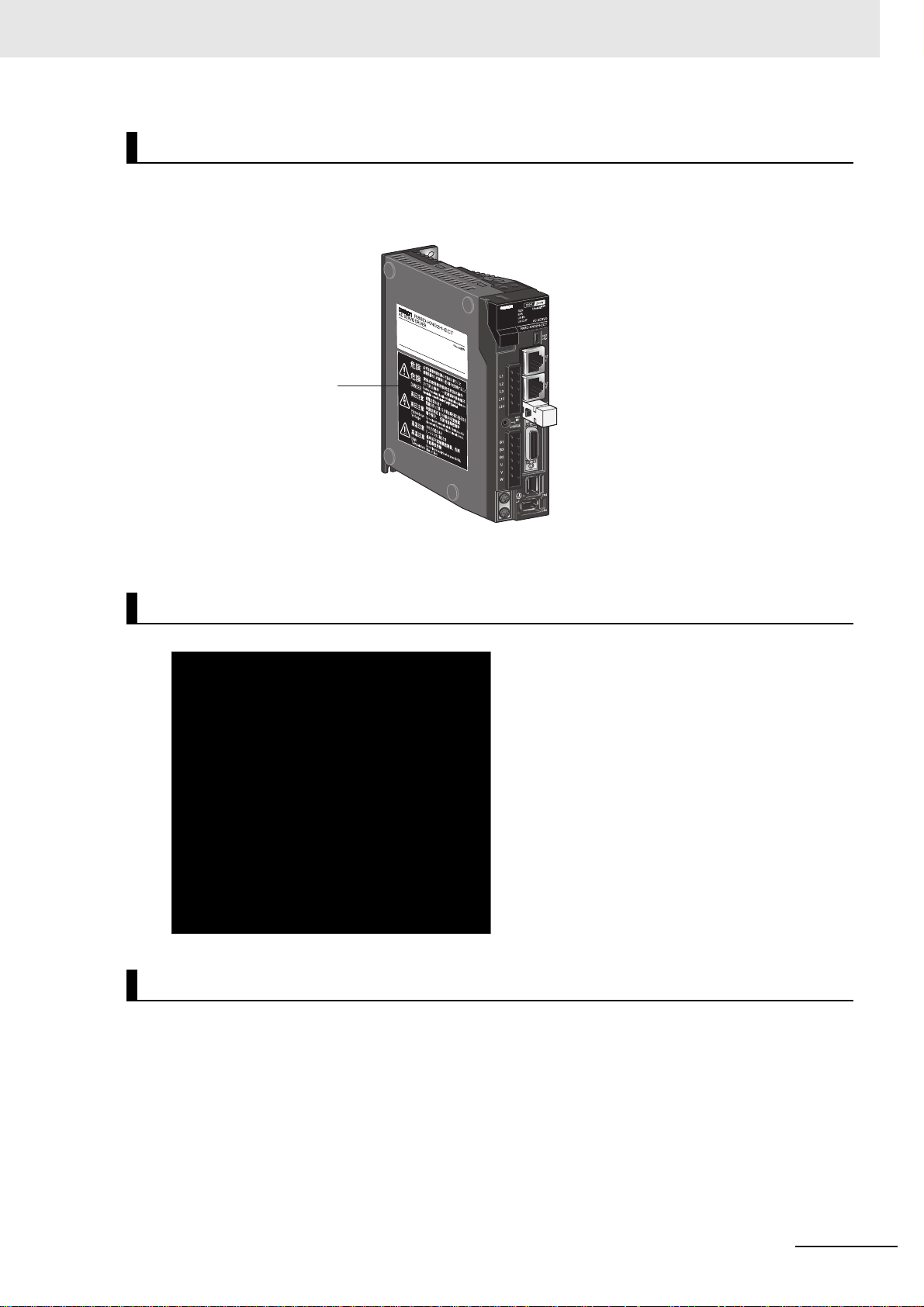
Location of Warning Label
(R88D-KN02H-ECT-L)
Location of Warning Label
The Servo Drive bears a warning label at the following location to provide handling warnings.
When handling the Servo Drive, be sure to observe the instructions provided on this label.
Instructions on Warning Label
Disposal
• Dispose of the Servo Drive as industrial waste.
• When disposing of the battery, insulate it using tape and dispose of it by following the applicable
ordinance of your local government.
G5-series Linear Motors/Servo Drives With Built-in EtherCAT Communications
23
Page 26
Regulations and Standards
Regulations and Standards
Overseas Use
To export (or provide to nonresident aliens) any part of this product that falls under the category of
goods (or technologies) for which an export certifica te or license is ma ndato ry accordi ng to the For eign
Exchange and Foreign Trade Control Law of Japan, an export certificate or license (or service
transaction approval) according to this law is required.
Conformance to EC Directives
For the G5-series Servo Drive which is an EC-compliant product, it is the user’s responsibility to check
and ensure the compliance of the equipment and the entire system with the applicable EC Directives.
EC Directive Product Applicable standards
Low Voltage Directive AC Servo Drives EN61800-5-1
Linear Motor EN60034-1
EMC Directive AC Servo Drives EN55011 classA group1
EN61000-6-2
EN61800-3
Machinery Directives AC Servo Drives EN954-1 Cat.3
EN ISO13849-1 PL c, PL d
EN61508 (Part 1, 2, 4) SIL2
EN62061 SIL2
EN61800-5-2 (STO)
IEC61326-3-1
Note To conform to EMC Directives, the Servo Drive must be installed under the conditions described in 4-3
Wiring Conforming to EMC Directives on page 4-26.
24
G5-series Linear Motors/Servo Drives With Built-in EtherCAT Communications
Page 27
Precautions for Correct UsePrecautions for Correct Use
UL and cUL Standards
Standard Product Applicable standards File number
UL standards AC Servo Drives UL 508C
CSA standards AC Servo Drives CSA C22.2 No. 14 E179149
*1 The R88D-KT20 and lower capacity Servo Drives are UL-listed .
The R88D-KT30 and higher capacity Servo Drives are UL-recognized.
This product complies with the UL 508C standard (file No. E179149) only when the following two
installation conditions are met.
Use the Servo Drive in an environment rated as Pollution Degree 2 or Pollution Degree 1 defined in
•
IEC60664-1. For example, the product meets this requirement when installed inside an IP54 control panel.
• Be sure to connect between the power supply and the no ise filter a circuit breaker or fuse that bears
the mark (which means a UL-listed product).
Refer to the following table for the rated current of the circuit breaker/fuse.
For wiring, use a copper conductor wire with a temperature rating of 75 ºC or higher.
Regulations and Standards
E179149
*1
Servo Drive model Circuit breaker rated current [A]
R88D-KN01L-ECT-L 10
R88D-KN02L-ECT-L
R88D-KN04L-ECT-L
R88D-KN01H-ECT-L
R88D-KN02H-ECT-L
R88D-KN04H-ECT-L
R88D-KN08H-ECT-L 15
R88D-KN10H-ECT-L
R88D-KN15H-ECT-L 20
R88D-KN06F-ECT-L 15
R88D-KN10F-ECT-L
R88D-KN15F-ECT-L
R88D-KN20F-ECT-L 20
R88D-KN30F-ECT-L 30
Korean Radio Regulations (KC)
• The G5-series Servo Drives comply with the Korean Radio Regulations (KC).
• The G5-series Servomotors and Linear Motors are exempt from the Korean Radio Regulations (KC).
SEMI F47
• Servo Drives conform to the SEMI F47 standard for momentary power interruptions (voltage sag
immunity) for no-load or light-load operation.
• This standard applies to semiconductor manufacturing equipment.
• It does not apply to Servo Drives with single-phase 100-V specifications or with 24 VDC
specifications for the control power input.
• Always perform evaluation testing for SEMI F47 compliance in the actual system.
G5-series Linear Motors/Servo Drives With Built-in EtherCAT Communications
25
Page 28

Regulations and Standards
Trademarks
• Sysmac and SYSMAC are trademarks or registered trademarks of OMRON Corporation in Japan
and other countries for OMRON factory automation products.
• EtherCAT
GmbH, Germany.
Other company names and product names in this document are the trademarks or reg istered
trademarks of their respective companies.
® is registered trademark and patented technology, licensed by Beckhoff Automation
26
G5-series Linear Motors/Servo Drives With Built-in EtherCAT Communications
Page 29

Items to Check after Unpacking
VOLTAGE
100~120V
1Ø 3Ø
0-120V
INPUT OUTPUT
PHASE
2.6A
50/60Hz
0~500.0Hz
1.7A
100W
A09080004
FREQ
POWER
OMRON Corporation
MADE IN JAPAN
SERIAL No.
F L C
Warning label
display location
(R88D-KN02H-ECT-L)
Items to Check after Unpacking
After unpacking, check the following items.
• Is this the model you ordered?
• Was there any damage sustained during shipment?
Servo Drive
Location of Servo Drive Rating Label
Servo Drive Rating Label
G5-series Linear Motors/Servo Drives With Built-in EtherCAT Communications
27
Page 30
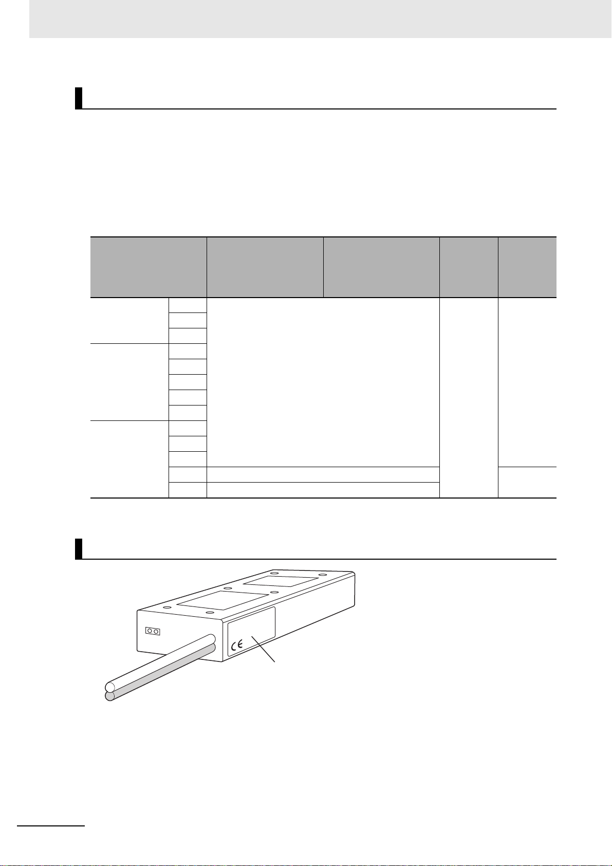
Items to Check after Unpacking
Location of Rating Label
Servo Drive Accessories
Safety Precautions document × 1 copy
• Connectors, mounting screws, mounting brackets, and other accessories other than those in the
table below are not supplied. They must be prepared by the customer.
• The safety bypass connector is required if the safety function is not used. To use the safety function,
provide a separate safety I/O signal connector.
• If any item is missing or a problem is found such as Servo Drive damage, contact the OMRON dealer
or sales office where you purchased your product.
Connector for main
circuit power supply
Specifications
Single-phase
100 VAC
Single-phase/
3-phase
200 VAC
3-phase
400 VAC
*1 Provide a safety connector separately to use the safety function.
100 W Included
200 W
400 W
200 W
400 W
750 W
1 kW
1.5 kW
600 W
1 kW
1.5 kW
2 kW Included Included
3 kW –
terminals and control
circuit power supply
terminals
Connector for External
Regeneration Resistor
connection terminals
and motor connection
terminals
Safety
bypass
connector
Included
*1
Mounting
brackets
–
28
Location of Iron-core Linear Motor Coil Unit Rating Label
G5-series Linear Motors/Servo Drives With Built-in EtherCAT Communications
Page 31

Items to Check after Unpacking
Protective cover
Location of Rating
Label
Location of Iron-core Linear Motor Magnet Track Rating Label
The iron-core Linear Motor Magnet Track bears no labels.
For the model and the production lot number, check the in formation pro vided on the produ ct packaging
box.
Iron-core Linear Motor Accessories
• Safety Precautions document × 1 copy
• Protective cover (for Magnet Track only) × 1
The Magnet Track has a protective cover for cushioning the
impact of collision due to the magnetic attraction force until
assembled. Do not remove this protective cover until you
finish installing the iron-core Linear Motor.
Parts such as connectors, mounting screws, and mounting
brackets are not included. Provide them separately. If any
item is missing or a problem is found such as product
damage, contact the OMRON dealer or sales office where
you purchased your product.
Location of Coreless Linear Motor Rating Label
Location of Rating Label
For the model and the production lot number, check the information provided on the rating label or the
product packaging box.
Coreless Linear Motor Attachments
• Safety Precautions document × 1 copy
Parts such as connectors, mounting screws, and mounting brackets are not included. Provide them
separately.
If any item is missing or a problem is found such as product damage, contact the OMRON dealer or
sales office where you purchased your product.
G5-series Linear Motors/Servo Drives With Built-in EtherCAT Communications
29
Page 32

Revision History
Revision History
The manual revision code is a number appended to the end of the catalog number found in the bottom
right-hand corner of the front and back covers.
Example
Cat. No.
Revision
code
01 October 2011 Original production
02 November 2012 Descriptions about Linear Motors were added.
03 January 2017 Added information and made corrections.
04 January 2018 Added information and made corrections.
Revision date Revised content
I577-E1-04
Revision code
30
G5-series Linear Motors/Servo Drives With Built-in EtherCAT Communications
Page 33

Features and System Configuration
This section explains the features of the Servo Drive and name of each part.
1-1 Outline . . . . . . . . . . . . . . . . . . . . . . . . . . . . . . . . . . . . . . . . . . . . . . . . . . . . . . . 1-2
1-1-1 Features of G5-series Servo Drives . . . . . . . . . . . . . . . . . . . . . . . . . . . . . . . . 1-2
1-1-2 What is EtherCAT? . . . . . . . . . . . . . . . . . . . . . . . . . . . . . . . . . . . . . . . . . . . . . 1-3
1-1-3 Object Dictionary . . . . . . . . . . . . . . . . . . . . . . . . . . . . . . . . . . . . . . . . . . . . . . . 1-3
1-2 System Configuration . . . . . . . . . . . . . . . . . . . . . . . . . . . . . . . . . . . . . . . . . . 1-4
1-3 Names and Functions . . . . . . . . . . . . . . . . . . . . . . . . . . . . . . . . . . . . . . . . . . 1-6
1-3-1 Servo Drive Part Names . . . . . . . . . . . . . . . . . . . . . . . . . . . . . . . . . . . . . . . . . 1-6
1-3-2 Servo Drive Functions . . . . . . . . . . . . . . . . . . . . . . . . . . . . . . . . . . . . . . . . . . . 1-7
1-4 System Block Diagram . . . . . . . . . . . . . . . . . . . . . . . . . . . . . . . . . . . . . . . . . 1-8
1
1-5 Unit Versions . . . . . . . . . . . . . . . . . . . . . . . . . . . . . . . . . . . . . . . . . . . . . . . . 1-12
1-5-1 Confirmation Method . . . . . . . . . . . . . . . . . . . . . . . . . . . . . . . . . . . . . . . . . . . 1-12
1-5-2 Unit Versions . . . . . . . . . . . . . . . . . . . . . . . . . . . . . . . . . . . . . . . . . . . . . . . . . 1-12
G5-series Linear Motors/Servo Drives With Built-in EtherCAT Communications
1 - 1
Page 34

1 Features and System Configuration
1-1 Outline
The G5-series AC Servo Drives With Built-in EtherCAT Communications, Linear Motor Type supports
100 Mbps EtherCAT.
When you use the G5-series Servo Drive with a Machine Automation Controller NJ-series (Model:
NJ301-/NJ501-) or EtherCAT-compatible Position Control Unit (Model:
CJ1W-NC8), you can construct a sophisticated positioning control system.
Also, you need only one communications cable to connect the Servo Drive and the Controller.
Therefore, you can realize a position control system easily with reduced wiring effort.
With real time autotuning, adaptive filter, notch filter, and damping control, you can set up a system that
provides stable operation by suppressing vibration in low-rigidity machines.
1-1-1 Features of G5-series Servo Drives
G5-series Servo Drives have the following features.
Optimal Functionality and Operability by Standardizing Specifications
*1
As a Sysmac Device
Motor Type is designed to provide optimal functionality and ease of use wh en used in conjunction with a
Machine Automation Controller such as NJ-series and the automation software Sysmac Studio.
*1 Sysmac Device is a generic term for OMRON control devices such as an EtherCAT Slave, designed with
unified communications specifications and user interface specifications.
, the G5-series AC Servo Drives With Built-in EtherCAT Communications, Linear
Data Transmission Using EtherCAT Communications
Combining the G5-series Servo Drive with a Ma ch in e Aut oma tion Controller NJ-series (Model:
NJ301-/NJ501-) or EtherCAT-compatible Position Control Unit (Model:
CJ1W-NC8) enables you to exchange all position in formatio n with the controller in high-speed data
communications.
Since the various control commands are transmitted via data communications, Servomotor’s
operational performance is maximized without being limited by interface specifications such as the
response frequency of the encoder feedback pulses.
You can use the Servo Drive’s various control parameters and monitor data on a host controller, and
unify the system data for management.
Safe Torque OFF (STO) Function to Ensure Safety
1 - 2
You can cut off the motor current to stop the motor based on a signal from an emergency sto p button or
other safety equipment. This can be used for an emergency stop circuit that is compliant with safety
standards without using an external contactor. Even during the torque (force) OFF status, the present
position of the motor is monitored by the control circuits to eliminate the need to perform an origin
search when restarting.
G5-series Linear Motors/Servo Drives With Built-in EtherCAT Communications
Page 35

1 Features and System Configuration
Suppressing Vibration of Low-rigidity Mechanisms during
Acceleration/Deceleration
The damping control function suppresses vibration of low-rigidity mechanisms or devices whose tips
tend to vibrate.
Two damping filters are provided to enable switching the damping fr equency automatically accor ding to
the movement direction and also via an external signal. In addition, the settings can be made easily by
setting the damping frequency and filter values.
1-1 Outline
1
1-1-2 What is EtherCAT?
EtherCAT is an open high-speed industrial network system that conforms to Ethernet (IEEE 802.3).
Each node achieves a short cycle time by transmitting Ethernet frames at high speed. A mechanism
that allows sharing clock information enables high-precision synchronization control with low
communications jitter.
“EtherCAT
® is registered trademark and patented technology, licensed by Beckhoff Automation GmbH,
Germany.”
1-1-3 Object Dictionary
G5-series AC Servo Drives With Built-in EtherCAT Communications, Linear Motor Type use the object
dictionary for CAN application protocol over EtherCAT (CoE) as a base for communications.
An object is a special data structure inside a device that consists of data, parameters, and methods.
An object dictionary is a data structure that describes the data type objects, communications objects,
and application objects.
All objects are assigned four-digit hexadec ima l numbers in the areas shown in the following table.
1-1-2 What is EtherCAT?
Indexes Area Contents
0000 to 0FFF hex Data Type Area Definitions of data types.
1000 to 1FFF hex CoE Communications
Area
2000 to 2FFF hex Manufacturer Specific
Area 1
3000 to 5FFF hex Manufacturer Specific
Area 2
6000 to 9FFF hex Device Profile Area Variables defined in the Servo Drive’s CiA402 drive profile.
A000 to FFFF hex Reserved Area Area reserved for future use.
*1 G5-series Servo Drive parameters (Pn) are allocated to objects 3000 to 3999 hex. Index 3 hex
correspond to G5-series Servo Drive parameters Pn. For example, object 3504 hex is the same as
parameter Pn504.
Pn uses decimal numbers but object 3 is a hexadecimal number.
For details on servo parameters, refer to Section 9 Servo Parameter Objects.
Definitions of variables that can be used by all servers for
designated communications.
Variables with common definitions for all OMRON products.
Variables with common definitions for all G5-series Servo
Drives (servo parameters).
*1
G5-series Linear Motors/Servo Drives With Built-in EtherCAT Communications
1 - 3
Page 36

1 Features and System Configuration
ID
2
11
0
1
3
2
4
5
7
6
8
9
11
10
12
13
14
15
DC24V
7mA
CO
M
M
ACH
N
o
.
AD042
RUN
E
RC
E
RH
B1 A1
x
10
1
x
10
0
0
9
8
7
6
5
4
3
2
1
0
9
8
7
6
5
4
3
2
1
EtherCAT
communications
NJ-series CPU Unit with built-in EtherCAT port
Controller (EtherCAT)
G5-series Servo Drive
R88D-KN-ECT-L
AC Servo Drive
CJ-series CPU Unit
+ Position Control Unit with EtherCAT Interface
Position Control Unit (NC)
CJ1W-NC8
100 VAC
200 VAC
400 VAC
Programmable Controller
CJ-CPU
Machine Automation Controller
NJ301-/NJ501-
1-2 System Configuration
The system configuration for a G5-series AC Servo Drive with Built-in EtherCAT Communications,
Linear Motor Type is shown below.
1 - 4
G5-series Linear Motors/Servo Drives With Built-in EtherCAT Communications
Page 37

1 Features and System Configuration
Motor power signal
I/O signal
Feedback signal
Linear Motor
Commercial Product
Serial Communications Cable
R88A-CRKE010SR
90° phase difference output cable
supplied by the user
External Encoder Cable
Power cable
supplied by the user
Power Cable
Iron-core family
External encoder
Connector-Terminal Block
Conversion Unit
XW2-20G
Cable
XW2Z-J-B34
Terminal Block and Cable
Ironless family
Motor Coil Unit: R88L-EC-FW-
Magnet Track: R88L-EC-FM-
Motor Coil Unit: R88L-EC-GW-
Magnet Track: R88L-EC-GM-
1-2 System Configuration
1
G5-series Linear Motors/Servo Drives With Built-in EtherCAT Communications
1 - 5
Page 38

1 Features and System Configuration
1-3 Names and Functions
This section describes the names and functions of Servo Drive parts.
1-3-1 Servo Drive Part Names
The Servo Drive part names are given below.
EtherCAT status indicators
Seven-segment display
Analog monitor connector
(CN5)
Rotary switches for
node address setting
USB connector (CN7)
supply terminals (L1, L2, and L3)
Main circuit power
Control circuit power supply terminals
(L1C and L2C)
Charge lamp
External Regeneration Resistor
connection terminals
(B1, B2, and B3)
Motor connection terminals
(U, V, and W)
EtherCAT communications
connector: ECAT IN
EtherCAT communications
connector: ECAT OUT
Safety connector (CN8)
Control I/O connector (CN1)
External encoder connector (CN4)
1 - 6
Protective ground terminals
Not used (CN2)
G5-series Linear Motors/Servo Drives With Built-in EtherCAT Communications
Page 39

1-3-2 Servo Drive Functions
The functions of each part are described below.
Display
A 2-digit 7-segment display shows the node ad dres s , er ror cod e s , and other Servo Drive status.
1 Features and System Configuration
1-3 Names and Functions
1
Charge Lamp
Lights when the main circuit power supply is turned ON.
EtherCAT Status Indicators
These indicators show the status of EtherCAT communications.
For details, refer to 5-1-2 Status Indicators on page 5-3.
Control I/O Connector (CN1)
Used for command input signals and I/O signals.
External Encoder Connector (CN4)
Connector for an external encoder signal.
EtherCAT Communications Connectors (ECAT IN and ECAT OUT)
Connectors for EtherCAT communications.
1-3-2 Servo Drive Functions
Analog Monitor Connector (CN5)
You can use a special cable to monitor values, such as the motor speed, force command value, etc.
USB Connector (CN7)
Communications connector for the computer.
Safety Connector (CN8)
Connector for safety devices.
If no safety devices are used, keep the factory-set safety bypass connector installed.
G5-series Linear Motors/Servo Drives With Built-in EtherCAT Communications
1 - 7
Page 40

1 Features and System Configuration
1-4 System Block Diagram
This is the block diagram of the G5-series AC Servo Drive with Built-in EtherCAT Communications,
Linear Motor Type.
z R88D-KN01L-ECT-L/-KN02L-ECT-L
R88D-KN01H-ECT-L/-KN02H-ECT-L/-KN04H-ECT-L
L1
L2
L3
L1C
L2C
CN A
FUSE
FUSE
GR
GR
FUSE
15 V
G1
5 V
3.3 V
2.5 V
1.5 V
E5V
±12 V
G2
+
-
+
-
SW power
supply main
circuit control
Internal
control
power supply
Voltage
detection
Regeneration
Relay
drive
control
Overcurrent
detection
MPU & ASIC
Position, speed, and force calculation
control area
• PWM control
Gate drive
Current detection
Display
and setting
circuit area
CN B
B1
B2
B3
U
V
W
FG
1 - 8
ECAT
IN
EtherCAT
communications
connector
communications
ECAT
OUT
EtherCAT
connector
CN1
interface
G5-series Linear Motors/Servo Drives With Built-in EtherCAT Communications
CN2 CN4 CN5 CN7
Not used
External
encoder
Analog
monitor
USB
CN8
SafetyControl
Page 41

1 Features and System Configuration
CN8CN2CN1
ECAT
IN
ECAT
OUT
15 V
G1
5 V
2.5 V
1.5 V
E5V
G2
3.3 V
FG
CN4 CN5 CN7
B1
B2
B3
CN B
U
V
W
GR
L2C
L1C
L3
L2
L1
FUSE
FUSE
FUSE
CN A
+
-
+
-
GR
±12 V
Axial-flow fan
Internal
Regeneration
Resistor
Overcurrent
detection
Current detection
Regeneration
control
Relay
drive
Gate drive
SW power
supply main
circuit control
Internal
control
power supply
MPU & ASIC
Position, speed, and force calculation
control area
• PWM control
Display
and setting
circuit area
Voltage
detection
USB
EtherCAT
communications
connector
EtherCAT
communications
connector
Not used
External
encoder
Analog
monitor
SafetyControl
interface
(except for the
R88D-KN04L-ECT-L/
-KN08H-ECT-L)
z R88D-KN04L-ECT-L/-KN08H-ECT-L/-KN10H-ECT-L/-KN15H-ECT-L
1-4 System Block Diagram
1
G5-series Linear Motors/Servo Drives With Built-in EtherCAT Communications
1 - 9
Page 42

1 Features and System Configuration
z R88D-KN06F-ECT-L/-KN10F-ECT-L/-KN15F-ECT-L/-KN20F-ECT-L
L1
L2
L3
24 V
0 V
CN A
FUSE
FUSE
CN C
GRGR
FUSE
15 V
G1
5 V
3.3 V
2.5 V
1.5 V
E5V
±12 V
G2
+
+
DC-DC
-
-
SW power
supply main
circuit control
Internal
control
power supply
CN D
B1
B2
CN B
B3
NC
U
V
W
FG
+
Internal
Regeneration
Resistor
-
Voltage
detection
Relay
drive
Regeneration
control
Overcurrent
detection
Gate drive
MPU & ASIC
Position, speed, and force calculation
Current detection
Display
and setting
circuit area
control area
• PWM control
Axial-flow fan
ECAT
IN
EtherCAT
communications
connector
ECAT
OUT
EtherCAT
communications
connector
interface
CN2CN1
Not used
CN4 CN5 CN7
External
encoder
Analog
monitor
USB
CN8
SafetyControl
1 - 10
G5-series Linear Motors/Servo Drives With Built-in EtherCAT Communications
Page 43

z R88D-KN30F-ECT-L
GRGR
0 V
24 V
L3
L2
L1
FUSE
FUSE
FUSE
CN A
CN C
+
-
+
-
+
-
15 V
G1
5 V
2.5 V
1.5 V
E5V
G2
3.3 V
FG
CN4 CN5 CN7
B1
B2
B3
NC
CN D
CN B
U
V
W
CN8
DC-DC
CN2CN1
ECAT
IN
ECAT
OUT
±12 V
Axial-flow fan
Internal
Regeneration
Resistor
SW power
supply main
circuit control
Internal
control
power supply
MPU & ASIC
Position, speed, and force calculation
control area
• PWM control
Display
and setting
circuit area
Voltage
detection
USB
EtherCAT
communications
connector
EtherCAT
communications
connector
Not used
External
encoder
Analog
monitor
SafetyControl
interface
Overcurrent
detection
Current detection
Regeneration
control
Relay
drive
Gate drive
1 Features and System Configuration
1-4 System Block Diagram
1
G5-series Linear Motors/Servo Drives With Built-in EtherCAT Communications
1 - 11
Page 44

1 Features and System Configuration
VOLTAGE
100~120V
1Ø 3Ø
0-120V
INPUT OUTPUT
PHASE
2.6A
50/60Hz
0~500.0Hz
1.7A
100W
A09080004
FREQ
POWER
OMRON Corp
oration
MADE IN JAPAN
SERIAL No.
F L C
(R88D-KN01L-ECT-L)
Nameplate location
Unit V ersion
Here, the unit version is 1.1.
Product Nameplate
1-5 Unit Versions
The G5-series Servo Drive uses unit versions. Unit versions are used to manage differences in
supported functions when product upgrades are made.
1-5-1 Confirmation Method
The unit version of a G5-series Servo Drive is given on the product’s nameplate as shown below.
1-5-2 Unit Versions
Unit version
Ver. 1.0 New release Ver. 2.70 or higher
Ver. 1.1 Added the Linear Motor Setup function. Ver. 2.70 or higher
Upgraded content
Supported CX-Drive versions
1 - 12
G5-series Linear Motors/Servo Drives With Built-in EtherCAT Communications
Page 45

Models and External Dimensions
This section explains the models of Servo Drive, Linear Moto rs, and peripheral devices,
and provides the external dimensions and mounting dimensions.
2-1 Servo System Configuration . . . . . . . . . . . . . . . . . . . . . . . . . . . . . . . . . . . . . 2-2
2-2 How to Read Model Numbers . . . . . . . . . . . . . . . . . . . . . . . . . . . . . . . . . . . . 2-4
2-2-1 Servo Drive . . . . . . . . . . . . . . . . . . . . . . . . . . . . . . . . . . . . . . . . . . . . . . . . . . . 2-4
2-2-2 Linear Motor . . . . . . . . . . . . . . . . . . . . . . . . . . . . . . . . . . . . . . . . . . . . . . . . . . . 2-5
2-3 Model Tables . . . . . . . . . . . . . . . . . . . . . . . . . . . . . . . . . . . . . . . . . . . . . . . . . 2-7
2-3-1 Servo Drive Model Table . . . . . . . . . . . . . . . . . . . . . . . . . . . . . . . . . . . . . . . . . 2-7
2-3-2 Linear Motor Model Table . . . . . . . . . . . . . . . . . . . . . . . . . . . . . . . . . . . . . . . . 2-7
2-3-3 Servo Drive and Linear Motor Combination Tables . . . . . . . . . . . . . . . . . . . . . 2-8
2-3-4 Cable and Peripheral Device Model Tables . . . . . . . . . . . . . . . . . . . . . . . . . 2-10
2-4 External and Mounting Dimensions . . . . . . . . . . . . . . . . . . . . . . . . . . . . . . 2-12
2-4-1 Servo Drive Dimensions . . . . . . . . . . . . . . . . . . . . . . . . . . . . . . . . . . . . . . . . 2-12
2-4-2 Linear Motor Dimensions . . . . . . . . . . . . . . . . . . . . . . . . . . . . . . . . . . . . . . . . 2-20
2-4-3 External Regeneration Resistor Dimensions . . . . . . . . . . . . . . . . . . . . . . . . . 2-27
2-4-4 Reactor Dimensions . . . . . . . . . . . . . . . . . . . . . . . . . . . . . . . . . . . . . . . . . . . 2-28
2-4-5 Mounting Bracket Dimensions . . . . . . . . . . . . . . . . . . . . . . . . . . . . . . . . . . . . 2-31
2
G5-series Linear Motors/Servo Drives With Built-in EtherCAT Communications
2 - 1
Page 46

2 Models and External Dimensions
ID
2
11
0
1
3
2
4
5
7
6
8
9
11
10
12
13
14
15
DC24V
7mA
CO
M
M
ACH
N
o
.
AD042
RUN
E
RC
ERH
B1 A1
x
10
1
x
10
0
0
9
8
7
6
5
4
3
2
1
0
9
8
7
6
5
4
3
2
1
CX-Drive
WS02-DRVC1
Support SoftwareSupport Software
(
)
NJ-series CPU Unit with EtherCAT Port
Controller
Automation Software
Sysmac Studio
Support Software
CJ-series CPU Unit
+ Position Control Unit with EtherCAT Interface
Position Control Unit (NC)
CJ1W-NC8
Programmable Controller
CJ-CPU
CX-One FA Integrated Tool Package
CX-Programmer,
CX-Position,
and CX-Motion
Machine Automation Controller
NJ301-/NJ501-
2-1 Servo System Configuration
2 - 2
G5-series Linear Motors/Servo Drives With Built-in EtherCAT Communications
Page 47

2 Models and External Dimensions
USB communications
EtherCAT
communications
G5-series Servo Drive
R88D-KN-ECT-L
Motor power signal
I/O signal
Feedback signal
AC Servo Drive
Peripheral Devices
Reactor
3G3AX-DL
3G3AX-AL
External
Regeneration
Resistors
R88A-RR
Linear Motor
100 VAC
200 VAC
400 VAC
Commercial Product
Serial Communications Cable
R88A-CRKE010SR
90° phase difference output cable
supplied by the user
External Encoder Cable
Motor power cable
Supplied by the user
Motor power cable
External Encoder Cable
Connector-Terminal Block
Conversion Unit
XW2-20G
Cable
XW2Z-
J-B34
Terminal Block and Cable
Use these connectors when making
your own cable.
Control I/O Signal Connector (CN1)
R88A-CNW01C
External Encoder Connector (CN4)
R88A-CNK41L
Safety Connector (CN8)
R88A-CNK81S
Peripheral Conector
Iron-core family
Ironless family
Motor Coil Unit: R88L-EC-FW-
Magnet Track: R88L-EC-FM-
Motor Coil Unit: R88L-EC-GW-
Magnet Track: R88L-EC-GM-
2-1 Servo System Configuration
2
G5-series Linear Motors/Servo Drives With Built-in EtherCAT Communications
2 - 3
Page 48

2 Models and External Dimensions
: 100 W
: 200 W
: 400 W
: 600 W
: 750 W
: 1 kW
: 1.5 kW
: 2 kW
: 3 kW
01
02
04
06
08
10
15
20
30
R88D-KN01H-ECT-L
L: Linear Motor Type
ECT: EtherCAT
L : 100 VAC
H : 200 VAC
F : 400 VAC
N: Network
Motor Type
Communications Type
G5-series Servo Drive
Drive Type
Power Supply Voltage
Maximum Applicable
Linear Motor Capacity
2-2 How to Read Model Numbers
This section describes how to read and understand the model numbers of Servo Drives and Linear
Motors.
2-2-1 Servo Drive
The Servo Drive model number tells the Servo Drive type, power supply voltage, etc.
2 - 4
G5-series Linear Motors/Servo Drives With Built-in EtherCAT Communications
Page 49

2-2-2 Linear Motor
R88L-EC-FW-0303-ANPC
03 : 30 mm
06 : 60 mm
11 : 110 mm
FW: Iron-core family
Motor Coil Unit
03 :
06 :
09 :
12 :
15 :
A : Ver.A
C: Compact type
NP: Not provided
Coil Model
Version
Connector
Type
G5-series Linear Motor
Component Type
Effective Magnet Width
3-coil
6-coil
9-coil
12-coil
15-coil
R88L-EC-FM-03096-A
03 : 30 mm
06 : 60 mm
11 : 110 mm
FM: Iron-core family
Magnet Track
096 : 96 mm
144 : 144 mm
192 : 192 mm
288 : 288 mm
384 : 384 mm
A : Ver.A
Magnet Track Unit Length
Version
G5-series Linear Motor
Component Type
Effective Magnet Width
Two models of Linear Motors are available: iron-core family and ironless family. For each of these
models, the model numbers of the Motor Coil Unit and Magnet Track are defined as follows.
Iron-core family
z Motor Coil Uni
2 Models and External Dimensions
2-2 How to Read Model Numbers
2
2-2-2 Linear Motor
z Magnet Track
G5-series Linear Motors/Servo Drives With Built-in EtherCAT Communications
2 - 5
Page 50

2 Models and External Dimensions
R88L-EC-GW-0303-ANPS
03 : 30 mm
05 : 50 mm
07 : 70 mm
GW: Ironless family
Motor Coil Unit
03 :
06 :
09 :
A : Ver.A
NP: Not provided
S: Standard type
Coil Model
Version
Connector
Type
G5-series Linear Motor
Component Type
Effective Magnet Width
3-coil
6-coil
9-coil
A
Ironless family
z Motor Coil Unit
z Magnet Track
2 - 6
G5-series Linear Motor
Component Type
GM: Ironless family
Magnet Track
Effective Magnet Width
03 : 30 mm
05 : 50 mm
07 : 70 mm
Magnet Track Unit Length
090 : 90 mm
114 : 114 mm
120 : 120 mm
126 : 126 mm
168 : 168 mm
171 : 171 mm
210 : 210 mm
390 : 390 mm
456 : 456 mm
546 : 546 mm
Version
A : Ver.A
R88L-EC-GM-03090-
G5-series Linear Motors/Servo Drives With Built-in EtherCAT Communications
Page 51

2-3 Model Tables
2 Models and External Dimensions
This section lists the standard models of Servo Drives, Connectors, and peripheral equipment.
2-3-1 Servo Drive Model Table
The table below shows the Servo Drive models.
Specifications Model
Single-phase 100 VAC 100 W R88D-KN01L-ECT-L
Single-phase/3-phase 200 VAC 100 W R88D-KN01H-ECT-L
3-phase 400 VAC 600 W R88D-KN06F-ECT-L
200 W R88D-KN02L-ECT-L
400 W R88D-KN04L-ECT-L
200 W R88D-KN02H-ECT-L
400 W R88D-KN04H-ECT-L
750 W R88D-KN08H-ECT-L
1 kW R88D-KN10H-ECT-L
1.5 kW R88D-KN15H-ECT-L
1 kW R88D-KN10F-ECT-L
1.5 kW R88D-KN15F-ECT-L
2 kW R88D-KN20F-ECT-L
3 kW R88D-KN30F-ECT-L
2-3 Model Tables
2
2-3-1 Servo Drive Model Table
2-3-2 Linear Motor Model Table
The table below shows the Linear Motor models.
Iron-core Linear Motors
Motor Coil Unit model
R88L-EC-FW-0303-ANPC 48 105 R88L-EC-FM-03096-A
R88L-EC-FW-0306-ANPC 96 210
R88L-EC-FW-0606-ANPC 160 400 R88L-EC-FM-06192-A
R88L-EC-FW-0609-ANPC 240 600
R88L-EC-FW-0612-ANPC 320 800
R88L-EC-FW-1112-ANPC 608 1,600 R88L-EC-FM-11192-A
R88L-EC-FW-1115-ANPC 760 2,000
*1 The continuous force is subject to temperature conditions. For details, refer to 3-3-2 Performance
Specifications of Iron-core Linear Motors on page 3-29.
Continuous
force
*1
[N]
Momentary
maximum force
[N]
Magnet Track model
R88L-EC-FM-03144-A
R88L-EC-FM-03384-A
R88L-EC-FM-06288-A
R88L-EC-FM-11288-A
G5-series Linear Motors/Servo Drives With Built-in EtherCAT Communications
2 - 7
Page 52

2 Models and External Dimensions
Ironless Linear Motors
Motor Coil Unit model
R88L-EC-GW-0303-ANPS 26.5 100 R88L-EC-GM-03090-A
R88L-EC-GW-0306-ANPS 53 200
R88L-EC-GW-0309-ANPS 80 300
R88L-EC-GW-0503-ANPS 58 240 R88L-EC-GM-05126-A
R88L-EC-GW-0506-ANPS 117 480
R88L-EC-GW-0509-ANPS 175 720
R88L-EC-GW-0703-ANPS 117 552 R88L-EC-GM-07114-A
R88L-EC-GW-0706-ANPS 232 1,110
R88L-EC-GW-0709-ANPS 348 1,730
*1 The continuous force is subject to temperature conditions. For details, refer to 3-3-6 Performance
Specifications of Ironless Linear Motors on page 3-36.
Continuous
*1
force
[N]
Momentary
maximum force
[N]
R88L-EC-GM-03120-A
R88L-EC-GM-03390-A
R88L-EC-GM-05168-A
R88L-EC-GM-05210-A
R88L-EC-GM-05546-A
R88L-EC-GM-07171-A
R88L-EC-GM-07456-A
2-3-3 Servo Drive and Linear Motor Combination Tables
The following table shows appropriate combinations with G5-series AC Servo Drives and Linear
Motors.
Magnet Track model
Iron-core family
Motor Coil Unit model Voltage [V] Servo Drive model
R88L-EC-FW-0303-ANPC 100 R88D-KN01L-ECT-L 2.5
200 R88D-KN02H-ECT-L 5
400 R88D-KN06F-ECT-L 10
R88L-EC-FW-0306-ANPC 100 R88D-KN02L-ECT-L 2.5
200 R88D-KN04H-ECT-L 5
400 R88D-KN10F-ECT-L 10
R88L-EC-FW-0606-ANPC 100 R88D-KN04L-ECT-L 2
200 R88D-KN08H-ECT-L 4
400 R88D-KN15F-ECT-L 8
R88L-EC-FW-0609-ANPC 200 R88D-KN10H-ECT-L 4
400 R88D-KN20F-ECT-L 8
R88L-EC-FW-0612-ANPC 200 R88D-KN15H-ECT-L 4
400 R88D-KN30F-ECT-L 8
R88L-EC-FW-1112-ANPC 200 R88D-KN15H-ECT-L 2
400 R88D-KN30F-ECT-L 4
R88L-EC-FW-1115-ANPC 200 R88D-KN15H-ECT-L 2
400 R88D-KN30F-ECT-L 4
Maximum speed
[m/s]
2 - 8
Note The maximum operation speed is restricted by the guide mechanism, encoder, and other aspects. If it is
5 m/s or higher, please consult with your OMRON represe ntative.
G5-series Linear Motors/Servo Drives With Built-in EtherCAT Communications
Page 53

Ironless family
2 Models and External Dimensions
Motor Coil Unit model Voltage [V] Servo Drive model
R88L-EC-GW-0303-ANPC 100 R88D-KN01L-ECT-L 8
200 R88D-KN02H-ECT-L 16
R88L-EC-GW-0306-ANPC 100 R88D-KN04L-ECT-L 8
200 R88D-KN08H-ECT-L 16
R88L-EC-GW-0309-ANPC 200 R88D-KN10H-ECT-L 16
R88L-EC-GW-0503-ANPC 100 R88D-KN01L-ECT-L 2.2
200 R88D-KN01H-ECT-L 4.4
R88L-EC-GW-0506-ANPC 100 R88D-KN02L-ECT-L 2.2
200 R88D-KN04H-ECT-L 4.4
R88L-EC-GW-0509-ANPC 100 R88D-KN04L-ECT-L 2.2
200 R88D-KN08H-ECT-L 4.4
R88L-EC-GW-0703-ANPC 100 R88D-KN02L-ECT-L 1.2
200 R88D-KN04H-ECT-L 2.4
R88L-EC-GW-0706-ANPC 100 R88D-KN04L-ECT-L 1.2
200 R88D-KN08H-ECT-L 2.4
R88L-EC-GW-0709-ANPC 200 R88D-KN10H-ECT-L 2.4
Note The maximum operation speed is restricted by the guide mechanism, encoder, and other aspects. If it is
5 m/s or higher, please consult with your OMRON representative.
Maximum speed
[m/s]
2-3 Model Tables
2
2-3-3 Servo Drive and Linear Motor Combination Tables
G5-series Linear Motors/Servo Drives With Built-in EtherCAT Communications
2 - 9
Page 54

2 Models and External Dimensions
2-3-4 Cable and Peripheral Device Model Tables
The following tables show the models of EtherCAT communica tions cables (recommend ed) and analog
monitor cables, as well as the models of peripheral devices such as External Regeneration Resistors
and Reactors.
EtherCAT Communications Cable (Recommended)
Size x Number of cable cores (pairs) Recommended manufacturer Model
AWG24 x 4P Tonichi Kyosan Cable, Ltd. NETSTAR-C5E SAB 0.5 x 4P
Kuramo Electric Co. KETH-SB
SWCC Showa Cable Systems Co. FAE-5004
AWG22 x 2P Kuramo Electric Co. KETH-PSB-OMR
Ethernet Category 5 (100BASE-TX) or higher (twisted-pair cable with double, aluminum tape and
braided shielding) is recommended.
Analog Monitor Cable
Name Model
Analog Monitor Cable 1 m R88A-CMK001S
Connectors
Name Model
Control I/O Connector (CN1) R88A-CNW01C
External Encoder Connector (CN4) R88A-CNK41L
Safety Connector (CN8) R88A-CNK81S
Control Cables
Name Model
Connector-terminal Block Cables 1 m XW2Z-100J-B34
2 m XW2Z-200J-B34
Connector-terminal Blocks M3 screws XW2B-20G4
M3.5 screws XW2B-20G5
M3 screws XW2D-20G6
2 - 10
G5-series Linear Motors/Servo Drives With Built-in EtherCAT Communications
Page 55

2 Models and External Dimensions
External Regeneration Resistors
Specifications Model
Regeneration process capacity: 20 W, 50 Ω (with 150°C thermal sensor) R88A-RR08050S
Regeneration process capacity: 20 W, 100 Ω (with 150°C thermal sensor) R88A-RR080100S
Regeneration process capacity: 70 W, 47 Ω (with 150°C thermal sensor) R88A-RR22047S1
Regeneration process capacity: 180 W, 20 Ω (with 200°C thermal sensor) R88A-RR50020S
Reactor
Applicable Servo Drives
Model Number of power phases
R88D-KN01L-ECT-L Single-phase input 3G3AX-DL2004
R88D-KN02H-ECT-L 3G3AX-DL2007
R88D-KN04L-ECT-L 3G3AX-DL2015
R88D-KN01H-ECT-L Single-phase input 3G3AX-DL2002
3-phase input 3G3AX-AL2025
R88D-KN02H-ECT-L Single-phase input 3G3AX-DL2004
3-phase input 3G3AX-AL2025
R88D-KN04H-ECT-L Single-phase input 3G3AX-DL2007
3-phase input 3G3AX-AL2025
R88D-KN08H-ECT-L Single-phase input 3G3AX-DL2015
3-phase input 3G3AX-AL2025
R88D-KN10H-ECT-L Single-phase input 3G3AX-DL2015
3-phase input 3G3AX-AL2025
R88D-KN15H-ECT-L Single-phase input 3G3AX-DL2022
3-phase input 3G3AX-AL2025
R88D-KN06F-ECT-L 3-phase input 3G3AX-AL4025
R88D-KN10F-ECT-L
R88D-KN15F-ECT-L
R88D-KN20F-ECT-L 3G3AX-AL4055
R88D-KN30F-ECT-L
Reactor type
2-3 Model Tables
2
2-3-4 Cable and Peripheral Device Model Tables
Mounting Brackets (L-Brackets for Rack Mounting)
Applicable Servo Drives Model
R88D-KN01L-ECT-L/-KN01H-ECT-L/-KN02H-ECT-L R88A-TK01K
R88D-KN02L-ECT-L/-KN04H-ECT-L R88A-TK02K
R88D-KN04L-ECT-L/-KN08H-ECT-L R88A-TK03K
R88D-KN10H-ECT-L/-KN15H-ECT-L/-KN06F-ECT-L/-KN10F-ECT-L/-KN15F-ECT-L R88A-TK04K
Note Servo Drives with 2 kW or greater includes a mounting bracket. Use it when installing the Servo Drive using
front mounting.
G5-series Linear Motors/Servo Drives With Built-in EtherCAT Communications
2 - 11
Page 56

2 Models and External Dimensions
13270
40
150
40
28
6
150
140
2-M4
2-4 External and Mounting Dimensions
This section describes the external dimensions and the mounting dimensions of Servo Drives and
peripheral devices.
2-4-1 Servo Drive Dimensions
The dimensional description starts with a Servo Dr ive of the smallest capacity, which is followed by the
next smallest, and so on.
Single-phase 100 VAC: R88D-KN01L-ECT-L (100 W)
Single-phase/3-phase 100 VAC: R88D-KN01H-ECT-L/-KN02H-ECT-L
(100 to 200 W)
z Wall Mounting
External dimensions
Mounting dimensions
2 - 12
G5-series Linear Motors/Servo Drives With Built-in EtherCAT Communications
Page 57

2 Models and External Dimensions
40
7
180
170
150
5.2
R26
7
Ø5.2
2.5
132
19.5
7
2-M4
70
170
(42)*
(158)*
Rectangular
hole
* Rectangular hole dimensions are reference values.
z Front Mounting (Using Front Mounting Brackets)
2-4 External and Mounting Dimensions
External dimensions
Mounting dimensions
2
2-4-1 Servo Drive Dimensions
G5-series Linear Motors/Servo Drives With Built-in EtherCAT Communications
2 - 13
Page 58

2 Models and External Dimensions
55
150
132
150
43
6
55
140
70
2-M4
55
47
7
Ø5.2
180
170
150
7
5.2
R2.6
2.5
132
19.5
7
170
70
2-M4
(57)*
(158)*
Rectangular
hole
* Rectangular hole dimensions are reference values.
Single-phase 100 VAC: R88D-KN02L-ECT-L (200 W)
Single-phase/3-phase 200 VAC: R88D-KN04H-ECT-L (400 W)
z Wall Mounting
External dimensions Mounting dimensions
z Front Mounting (Using Front Mounting Brackets)
External dimensions
Mounting dimensions
2 - 14
G5-series Linear Motors/Servo Drives With Built-in EtherCAT Communications
Page 59

2 Models and External Dimensions
172
4
65
150
150
140
50
7.5
65
70
2-M4
65
40
20
Ø5.2
R2.6
20
40
5.2
180
170
150
172
4
19.5
2.5
170
20
70
2-M4
(67)*
(158)*
Rectangular
hole
* Rectangular hole dimensions are reference values.
Single-phase 100 VAC: R88D-KN04L-ECT-L (400 W)
Single-phase/3-phase 200 VAC: R88D-KN08H-ECT-L (750 W)
z Wall Mounting
External dimensions Mounting dimensions
2-4 External and Mounting Dimensions
2
2-4-1 Servo Drive Dimensions
z Front Mounting (Using Front Mounting Brackets)
External dimensions
Mounting dimensions
G5-series Linear Motors/Servo Drives With Built-in EtherCAT Communications
2 - 15
Page 60

2 Models and External Dimensions
Single-phase/3-phase 200 VAC: R88D-KN10H-ECT-L/-KN15H-ECT-L
(1 to 1.5 kW)
z Wall Mounting
External dimensions Mounting dimensions
70
86
150
172
4
z Front Mounting (Using Front Mounting Brackets)
External dimensions
Ø5.2
86
60
10
40
Ø5.2
70
19.5
172
2-M4
140
8.5
150
70
86
Mounting dimensions
4
4-M4
R2.6
170
180
150
5.2
R2.6
5.2
10
40
2.5
* Rectangular hole dimensions are reference values.
170
11
Rectangular
hole
40
(88)*
(158)*
2 - 16
G5-series Linear Motors/Servo Drives With Built-in EtherCAT Communications
Page 61

2 Models and External Dimensions
92
150
172
4
150
140
70
14.5
70
2-M4
92
3-phase 400 VAC: R88D-KN06F-ECT-L/-KN10F-ECT-L/
-KN15F-ECT-L (600 W to 1.5 kW)
z Wall Mounting
External dimensions Mounting dimensions
2-4 External and Mounting Dimensions
2
2-4-1 Servo Drive Dimensions
z Front Mounting (Using Front Mounting Brackets)
External dimensions
172
* Rectangular hole dimensions are reference values.
Ø
R2.6
10
5.2
5.2 5.2
10
40
40
60
92
Ø
5.2
150
170
180
70
19.5
2.5
Mounting dimensions
4
Rectangular
18
hole
40
(94)*
(158)*
6
4-M4
170
G5-series Linear Motors/Servo Drives With Built-in EtherCAT Communications
2 - 17
Page 62

2 Models and External Dimensions
3-phase 400 VAC: R88D-KN20F-ECT-L (2 kW)
z Wall Mounting
External dimensions Mounting dimensions
94
85
17.5
42.5
5.2
50
Ø5.2
5.2
70
195 1.8
25
6-M4
168
26.5
50
94
R2.6
5.2 5.2
17.5
50
168
Ø5.2
188
198
R2.6
2.5
z Front Mounting (Using Front Mounting Brackets)
External dimensions Mounting dimensions
94
85
17.5
42.5
5.2
50
5.2
Ø
5.2
168
188
198
70
30.7
195
25
Rectangular
(176)*
hole
180
6-M4
180
2 - 18
R2.6
5.2 5.2
17.5
50
R2.6
Ø
5.2
2.5
26.5
50
(96)*
* Rectangular hole dimensions are reference values.
G5-series Linear Motors/Servo Drives With Built-in EtherCAT Communications
Page 63

2 Models and External Dimensions
Ø5.2
R2.6
Ø5.2
R2.6
100
5.2
5.2
65
15
15
130
100
65
5.2 5.2
220
240
250
50
240
220
130
100
15
214
3.5
70
6-M4
2.5
Ø
5.2
R2.6
Ø
5.2
R2.6
100
5.2
5.2
65
15
15
130
100
65
5.2 5.2
220
240
250
50
240
(228)*
(132)*
100
15
214
70
6-M4
2.5
40.7
* Rectangular hole dimensions are reference values.
Rectangular
hole
3-phase 400 VAC: R88D-KN30F-ECT-L (3 kW)
z Wall Mounting
2-4 External and Mounting Dimensions
External dimensions
z Front Mounting (Using Front Mounting Brackets)
Mounting dimensions
2
2-4-1 Servo Drive Dimensions
External dimensions
Mounting dimensions
G5-series Linear Motors/Servo Drives With Built-in EtherCAT Communications
2 - 19
Page 64

2 Models and External Dimensions
20
48
(11)
18.6±0.7
20.5±0.7
28
R2.5
89º
+0.15
-0.35
12.4±0.7
56
23.9±0.7
L1
28.6
0
-0.2
37.1±0.1
*1
9
+0.1
-0.2
450 min.
9.5
4.8
A
N-M4, effective thread depth 5
2-4-2 Linear Motor Dimensions
Iron-core Motors
z R88L-EC-FW-0303/-0306
Motor Coil Unit
2 - 20
*1 These values indicate mounting dimensions.
Model L1 [mm] Number of holes [N]
R88L-EC-FW-0303 79 +0.15/–0.35 4 0.72
R88L-EC-FW-0306 127 +0.15/–0.35 6 1.03
*2 The weight of a 450-mm cable is included.
Enlarged view
Mass*2 [kg]
G5-series Linear Motors/Servo Drives With Built-in EtherCAT Communications
of portion A
*1
0.3±0.1
Page 65

2 Models and External Dimensions
L3
12
12
48
L2
4848 48 48
40
27.5 48 48
82º
(20.5)
50
N-
Ø
6
*3
8.2
Ø
5 Depth 4
B
450 min.
L1
37.1 ±0.1
*1
0
-0.2
28.6
16
20
48
(11)
30.6±0.7
32.5±0.7
40
+0.1
-0.2
89º
R2.5
+0.15
-0.35
80
12.4 ±0.7
23.9 ±0.7
9.5
4.8
A
N-M4, effective thread depth 5
0.3±0.1
*1
Enlarged view
of portion A
Magnet Track
*3 Use M5 low head allen head bolts.
Model
L2
[mm]
R88L-EC-FM-03096-A 96 48 4 Approx. 0.22
R88L-EC-FM-03144-A 144 96 6 Approx. 0.32
R88L-EC-FM-03384-A 384 336 16 Approx. 0.85
L3
[mm]
Number of
holes [N]
Mass [kg]
Enlarged view of portion B
Depth
12
4
5
5.5
2-4 External and Mounting Dimensions
2
2-4-2 Linear Motor Dimensions
z R88L-EC-FW-0606/-0609/-0612
Motor Coil Unit
*1 These values indicate mounting dimensions.
Model L1 [mm] Number of holes [N]
R88L-EC-FW-0606 127 +0.15/–0.35 6 1.59
R88L-EC-FW-0609 175 +0.15/–0.35 8 2.15
R88L-EC-FW-0612 223 +0.15/–0.35 10 2.7
*2 The weight of a 450-mm cable is included.
G5-series Linear Motors/Servo Drives With Built-in EtherCAT Communications
Mass*2 [kg]
2 - 21
Page 66

2 Models and External Dimensions
0.3±0.1
*1
Enlarged view
of portion A
Magnet Track
Enlarged view of portion B
80
B
12 12
70
Depth
5
5.5
12
4
N-
*3
6
Ø
Ø
5 Depth 4
86º
27 (21)
48 4848 48 48
L3
L2
*3 Use M5 low head allen head bolts.
Model L2 [mm] L3 [mm] Numbe r of holes [N] Mass [kg]
R88L-EC-FM-06192-A 192 144 8 Approx. 0.77
R88L-EC-FM-06288-A 288 240 12 Approx. 1.15
z R88L-EC-FW-1112/-1115
Motor Coil Unit
20
N-M4, effective thread depth 5
48
8.2
(11)
36
R2.5
2 - 22
12.4±0.7
23.9±0.7
9.5
89º
65
+0.1
-0.2
130
55.6±0.7
57.5±0.7
+0.15
-0.35
4.8
*1 These values indicate mounting dimensions.
Model L1 [mm] Number of holes [N]
R88L-EC-FW-1112 223 +0.15/–0.35 15 4.89
R88L-EC-FW-1115 271 +0.15/–0.35 18 5.94
*2 The weight of a 450-mm cable is included.
450 min.
L1
A
Mass*2 [kg]
G5-series Linear Motors/Servo Drives With Built-in EtherCAT Communications
0
-0.2
28.6
41.1±0.1
Page 67

Magnet Track
1212
4826 48
88º
120
130
N-
Ø
6
*3
L2
48 4848 (22)
L3
12.2
Ø
5 Depth 8
12
5.5
5
Depth
8
Enlarged view of portion B
B
*3 Use M5 low head allen head bolts.
2 Models and External Dimensions
2-4 External and Mounting Dimensions
2
2-4-2 Linear Motor Dimensions
Model L2 [mm] L3 [mm] Number of holes [N] Mass [kg]
R88L-EC-FM-11192-A 192 144 8 Approx. 2.12
R88L-EC-FM-11288-A 288 240 12 Approx. 3.18
G5-series Linear Motors/Servo Drives With Built-in EtherCAT Communications
2 - 23
Page 68

2 Models and External Dimensions
N-Ø3.5
10
18.5
L2
20
3.5
L1
10
5.3
3.2
950 min.
Ø
7.5
4.4
(
Ø
4.5)
49
21
L3
30
L4
15
N-Ø4.5
(Depth4)
5.5±0.1
A
0.05
A
0.05
Motor Coil Unit mounting surface
Magnet Track mounting surface
Ironless Motors
z R88L-EC-GW-0303/-0306/-0309
Motor Coil Unit
Model L1 [mm] L2 [mm] Number of holes [N]
R88L-EC-GW-0303 78 60 4 0.2
R88L-EC-GW-0306 138 120 7 0.28
R88L-EC-GW-0309 198 180 10 0.36
*1 The weight of a 950-mm cableis included.
Mass*1 [kg]
Magnet Track
Model L3 [mm] L4 [mm] Number of holes [N] Mass [kg]
R88L-EC-GM-03090-A 90 60 3 Approx. 0.46
R88L-EC-GM-03120-A 120 90 4 Approx. 0.61
R88L-EC-GM-03390-A 390 360 13 Approx. 1.97
Combination diagram
5.5
68
2 - 24
21
5.5
G5-series Linear Motors/Servo Drives With Built-in EtherCAT Communications
Page 69

2 Models and External Dimensions
950 min.
4.9
12
24
28
L1
13
L2
5
N-
Ø
4.5
5.8
(
Ø
5.5)
9
Ø
9.2
42
L3
L4
2128.4
80
N-Ø5.5
(
Depth 6
)
8.2
8.2
105
28.4
8.2±0.1
A0.05
0.1
A
Motor Coil Unit mounting surface Magnet Track mounting surface
z R88L-EC-GW-0503/-0506/-0509
Motor Coil Unit
Model L1 [mm] L2 [mm] Number of holes [N]
R88L-EC-GW-0503 106 84 4 0.48
R88L-EC-GW-0506 190 168 7 0.71
R88L-EC-GW-0509 274 252 10 0.94
*1 The weight of a 950-mm cableis included.
2-4 External and Mounting Dimensions
2
Mass*1 [kg]
2-4-2 Linear Motor Dimensions
Magnet Track
Model L3 [mm] L4 [mm] Number of holes [N] Mass [kg]
R88L-EC-GM-05126-A 126 84 3 Approx. 1.49
R88L-EC-GM-05168-A 168 126 4 Approx. 1.98
R88L-EC-GM-05210-A 210 168 5 Approx. 2.47
R88L-EC-GM-05546-A 546 504 13 Approx. 6.43
Combination diagram
G5-series Linear Motors/Servo Drives With Built-in EtherCAT Communications
2 - 25
Page 70

2 Models and External Dimensions
15
23.8
38
L1
5
L2
11.5
6.4
950 min.
4.3
N-
Ø
5.3
Ø
11
(
Ø
6.5)
11
L4
L3
28.557
100
48
N-Ø6.5
(Depth 10)
16.5±0.1
A0.05 A
0.1
Motor Coil Unit mounting surface
Magnet Track mounting surface
z R88L-EC-GW-0703/-0706/-0709
Motor Coil Unit
Model L1 [mm] L2 [mm] Number of holes [N]
Mass*1 [kg]
R88L-EC-GW-0703 134 114 4 0.9
R88L-EC-GW-0706 248 228 7 1.32
R88L-EC-GW-0709 362 342 10 1.74
*1 The weight of a 950-mm cableis included.
Magnet Track
Model L3 [mm] L4 [mm] Number of holes [N] Mass [kg]
R88L-EC-GM-07114-A 114 57 2 Approx. 2.88
R88L-EC-GM-07171-A 171 114 3 Approx. 4.31
R88L-EC-GM-07456-A 456 399 8 Approx. 11.5
Combination diagram
16.5
124.8
2 - 26
16.5
48
G5-series Linear Motors/Servo Drives With Built-in EtherCAT Communications
Page 71

2 Models and External Dimensions
4.2
6
500
Ø3
(0.75 mm
2
)
Ø1.5
(0.3 mm
2
)
104
122
130
43.5
28
20
t1.2
Thermal switch output
4.2
6
500
Ø3
(0.75 mm
2
)
Ø1.5
(0.3 mm
2
)
200
220
230
62
48
20
t1.2
Thermal switch output
4325 10
78
76
40
5.3
360
386
402
2-4-3 External Regeneration Resistor Dimensions
R88A-RR08050S/-RR080100S
2-4 External and Mounting Dimensions
2
2-4-3 External Regeneration Resistor Dimensions
R88A-RR22047S1
R88A-RR50020S
G5-series Linear Motors/Servo Drives With Built-in EtherCAT Communications
2 - 27
Page 72

2 Models and External Dimensions
66
56
72
90
4-5.2 × 8
2-M4
98
85
Ground terminal (M4)
66
56
72
90
4-5.2 × 8
2-M4
98
95
Ground terminal (M4)
2-4-4 Reactor Dimensions
3G3AX-DL2002
3G3AX-DL2004
2 - 28
G5-series Linear Motors/Servo Drives With Built-in EtherCAT Communications
Page 73

3G3AX-DL2007
66
56
72
90
4-5.2 × 8
2-M4
98
105
Ground terminal (M4)
66
56
72
90
4-5.2 × 8
2-M4
98
115
Ground terminal (M4)
2 Models and External Dimensions
2-4 External and Mounting Dimensions
2
2-4-4 Reactor Dimensions
3G3AX-DL2015
G5-series Linear Motors/Servo Drives With Built-in EtherCAT Communications
2 - 29
Page 74

2 Models and External Dimensions
86
71
80
100
4-6 × 9
2-M4
116
105
Ground terminal (M4)
150
94
C
4060
A
Ro R So S To T
Y±1
50±1
Ro R So S To
T
4-Ø6
9.5
(Cutout)
Ground terminal (M5)
Terminal screw 6-
Ø
K
Terminal block
Connection Diagram
3G3AX-DL2022
3G3AX-AL2025/-AL2055/-AL4025/-AL4055/-AL2055
Model
3G3AX-AL2025 120 82 67 4
3G3AX-AL2055 120 98 75 4
3G3AX-AL4025 120 82 67 4
3G3AX-AL4055 120 98 75 5
A C Y K
Dimensions [mm]
2 - 30
G5-series Linear Motors/Servo Drives With Built-in EtherCAT Communications
Page 75

2 Models and External Dimensions
Ro R So S To T
C
Y±1X±1
W
55D
H
H1
A
Ro R So S To T
4-
Ø
6
W = Terminal width
Ground terminal (M6)
Terminal hole 6-
Ø
K
Connection Diagram
(Cutout)
2-M4 countersunk
2-C5
17
9.5
24 11±0.2
ø5.2
R2
R2
15
10
7
40
2.5
R1 max.
2.5
2-M4 countersunk
2-C5
17
9.5
5
11±0.2
5.2
2-R1
R2
R2
15
10
33
40
R1 max.
2.5
2.5
Mounting bracket for bottom sideMounting bracket for top side
3G3AX-AL2110/-AL2220/-AL4110/-AL4220
2-4 External and Mounting Dimensions
2
2-4-5 Mounting Bracket Dimensions
2-4-5 Mounting Bracket Dimensions
Model
A C D H H1 X Y K W
Dimensions [mm]
3G3AX-AL2110 150 103 70 170 108 60 80 5.3 12
3G3AX-AL2220 180 113 75 190 140 90 90 8.4 16.5
3G3AX-AL4110 150 116 75 170 106 60 98 5.0 12.5
3G3AX-AL4220 180 103 75 190 140 100 80 5.3 12
L-brackets for rack mounting are brackets attached to the top and bottom of a Servo Drive. Note that
each bracket has a different shape when you attach these L-brackets.
R88A-TK01K
G5-series Linear Motors/Servo Drives With Built-in EtherCAT Communications
2 - 31
Page 76

2 Models and External Dimensions
2-M4 countersunk
2-C5
17
9.5
30±0.2
15
10
R2
20
40
ø5.2
R2
2.5
R1 max.
2.5
2-M4 countersunk
2-C5
17
9.5
30±0.2
15
10
R2
2-R1
20
40
5.2
R2
2.5
R1 max.
2.5
Mounting bracket for top side Mounting bracket for bottom side
R88A-TK02K
Mounting bracket for top side Mounting bracket for bottom side
2-C5
17
9.5
24
R2
ø5.2
15
10
7
47
R88A-TK03K
2-M4 countersunk
18±0.2
R2
2.5
R1 max.
2.5
17
15
2-C5
9.5
R2
10
2-M4 countersunk
18±0.2
5
40
47
2-R1
5.2
R2
2.5
R1 max.
2.5
R88A-TK04K
Mounting bracket for bottom sideMounting bracket for top side
2-C5
17
15
9.5
R2
10
5
10
36±0.2
40±0.2
60
2-M4 countersunk
2.5
R2
2-ø5.2
R1 max.
2.5
2 - 32
G5-series Linear Motors/Servo Drives With Built-in EtherCAT Communications
2-C5
17
9.5
5.2
R2
15
10
10
19
36±0.2
4-R1
40±0.2
60
2-M4 countersunk
5.2
2.5
R2
R1 max.
2.5
Page 77

Specifications
This section provides the general specifications, characteristics, connector
specifications, I/O circuits of the Servo Drives and Linear Motors, as well as
specifications of other peripheral device s.
3-1 Servo Drive Specifications . . . . . . . . . . . . . . . . . . . . . . . . . . . . . . . . . . . . . . 3-2
3-1-1 General Specifications . . . . . . . . . . . . . . . . . . . . . . . . . . . . . . . . . . . . . . . . . . . 3-2
3-1-2 Characteristics . . . . . . . . . . . . . . . . . . . . . . . . . . . . . . . . . . . . . . . . . . . . . . . . . 3-3
3-1-3 EtherCAT Communications Specifications . . . . . . . . . . . . . . . . . . . . . . . . . . . 3-5
3-1-4 EtherCAT Communications Connector Specifications (RJ45) . . . . . . . . . . . . . 3-5
3-1-5 Control I/O Specifications (CN1) . . . . . . . . . . . . . . . . . . . . . . . . . . . . . . . . . . . 3-6
3-1-6 Control Input Circuits . . . . . . . . . . . . . . . . . . . . . . . . . . . . . . . . . . . . . . . . . . . . 3-8
3-1-7 Control Input Details . . . . . . . . . . . . . . . . . . . . . . . . . . . . . . . . . . . . . . . . . . . . 3-9
3-1-8 Control Output Circuits . . . . . . . . . . . . . . . . . . . . . . . . . . . . . . . . . . . . . . . . . 3-11
3-1-9 Control Output Details . . . . . . . . . . . . . . . . . . . . . . . . . . . . . . . . . . . . . . . . . . 3-12
3-1-10 External Encoder Specifications . . . . . . . . . . . . . . . . . . . . . . . . . . . . . . . . . . 3-16
3-1-11 External Encoder Connector Specifications (CN4) . . . . . . . . . . . . . . . . . . . . 3-17
3-1-12 Analog Monitor Connector Specifications (CN5) . . . . . . . . . . . . . . . . . . . . . . 3-21
3-1-13 USB Connector Specifications (CN7) . . . . . . . . . . . . . . . . . . . . . . . . . . . . . . 3-22
3-1-14 Safety Connector Specifications (CN8) . . . . . . . . . . . . . . . . . . . . . . . . . . . . . 3-22
3-2 Overload Characteristics (Electronic Thermal Function) . . . . . . . . . . . . . 3-25
3-3 Linear Motor Specifications . . . . . . . . . . . . . . . . . . . . . . . . . . . . . . . . . . . . 3-28
3-3-1 General Specifications of Iron-core Linear Motors . . . . . . . . . . . . . . . . . . . . 3-28
3-3-2 Performance Specifications of Iron-core Linear Motors . . . . . . . . . . . . . . . . . 3-29
3-3-3 Iron-core Linear Motor Speed - Force Characteristics . . . . . . . . . . . . . . . . . . 3-32
3-3-4 Temperature Sensor Specifications of Iron-core Linear Motors . . . . . . . . . . 3-35
3-3-5 General Specifications of Ironless Linear Motors . . . . . . . . . . . . . . . . . . . . . 3-36
3-3-6 Performance Specifications of Ironless Linear Motors . . . . . . . . . . . . . . . . . 3-36
3-3-7 Ironless Linear Motor Speed - Force Characteristics . . . . . . . . . . . . . . . . . . 3-39
3-3-8 Temperature Sensor Specifications of Ironless Linear Motors . . . . . . . . . . . 3-44
3-3-9 Cable Specifications . . . . . . . . . . . . . . . . . . . . . . . . . . . . . . . . . . . . . . . . . . . 3-45
3-4 Cable and Connector Specifications . . . . . . . . . . . . . . . . . . . . . . . . . . . . . 3-46
3-4-1 Resistance to Bending of Robot Cable . . . . . . . . . . . . . . . . . . . . . . . . . . . . . 3-46
3-4-2 External Encoder Cable Specifications . . . . . . . . . . . . . . . . . . . . . . . . . . . . . 3-47
3-4-3 Connector Specifications . . . . . . . . . . . . . . . . . . . . . . . . . . . . . . . . . . . . . . . . 3-48
3-4-4 EtherCAT Communications Cable Specifications . . . . . . . . . . . . . . . . . . . . . 3-49
3-4-5 Analog Monitor Cable Specifica ti o ns . . . . . . . . . . . . . . . . . . . . . . . . . . . . . . . 3-52
3-4-6 Control Cable Specifications . . . . . . . . . . . . . . . . . . . . . . . . . . . . . . . . . . . . . 3-53
3-5 External Regeneration Resistor Specifications . . . . . . . . . . . . . . . . . . . . 3-58
3-6 Reactor Specifications . . . . . . . . . . . . . . . . . . . . . . . . . . . . . . . . . . . . . . . . 3-59
3
G5-series Linear Motors/Servo Drives With Built-in EtherCAT Communications
3 - 1
Page 78

3 Specifications
3-1 Servo Drive Specifications
Select a Servo Drive that matches the Linear Motor to be used.
3-1-1 General Specifications
Item Specifications
Operating ambient
temperature and humidity
Storage ambient
temperature and humidity
Operating and storage
atmosphere
Vibration resistance
Insulation resistance Between power supply terminals/power terminals and FG terminal: 0.5 MΩ min. (at 500 VDC)
Dielectric strength Between power supply/power terminals and FG terminal: 1,500 VAC for 1 min at 50/60 Hz
Protective structure Built into panel
0 to 55°C, 20% to 85% max. (with no condensation)
–20 to 65°C, 20% to 85% max. (with no condensation)
No corrosive gases
2
10 to 60 Hz and at an acceleration of 5.88 m/s
resonance point)
or less (Not to be run continuously at a
Note 1 The above items reflect individual evaluation testing. The results may differ under compound conditions.
2 Disconnect all connections to the Servo Drive before attempting a megameter test (insulation resistance
measurement) on a Servo Drive. Failure to follow this guideline may result in damaging the Servo Drive.
3 Never perform dielectric strength or other megameter tests on the Servo Drive. Failure to follow this guideline may
result in damaging the internal elements.
4 Some Servo Drive parts will require maintenance. For details, refer to 12-5 Periodic Maintenance on page 12-35.
5 Following may be caused by incoming electrical noise (unstable, vibration, accoustic noise, etc.). In such case, refer
to 4-4 Noise Reduction on page 4-29 for measure to reduce noise.
z International standard
*1
EC Directives
UL standards UL 508C
CSA standards CSA C22.2 No.14
Korean Radio Regulations (KC) Compliant
*1 This Servo Drive is third-party certified in combination with rotary motor models. It is the user's responsibility to perform
final checks on the compliance of the entire system.
EMC Directive EN55011, EN61000-6-2, EN61800-3
Low Voltage
Directive
Machinery
Directives
EN 61800-5-1
EN954-1(Cat.3), EN ISO13849-1 (Cat.3)(PLc, d), ISO13849-1(Cat.3)(PLc, d),
EN61508(SIL2), EN62061(SIL2), EN61800-5-2 (STO), IEC61326-3-1 (SIL 2)
3 - 2
G5-series Linear Motors/Servo Drives With Built-in EtherCAT Communications
Page 79

3-1-2 Characteristics
3 Specifications
100-VAC Input Models
Item
Input power supply Main circuit Power supply capacity 0.4 kVA 0.5 kVA 0.9 kVA
Power supply voltage Single-phase 100 to 120 VAC (85 to 132 VAC) 50/60 Hz
Rated current 2.6 A 4.3 A 7.6 A
1
1
Control
circuit
Heat value*
Power supply voltage Single-phase 100 to 120 VAC (85 to 132 VAC) 50/60 Hz
Heat value*
Mass Approx. 0.8 kg Approx. 1.0 kg Approx. 1.6 kg
Maximum motor
capacity
Motor Rated Rms Current 1.7 Arms 2.5 Arms 4.6 Arms
Maximum current of motor 5.1 Arms 7.5 Arms 13.8 Arms
*1 The heat value is given for rated operation.
R88D-KN01L-ECT-L R88D-KN02L-ECT-L R88D-KN04L-ECT-L
16.6 W 21 W 25 W
4 W4 W4 W
200-VAC Input Models
Item
Input power supply Main circuit Power supply capacity 0.5 kVA 0.5 kVA 0.9 kVA
Power supply voltage Single-phase or 3-phase 200 to 240 VAC
Rated current
*2
*2
Control
circuit
Heat value
Power supply voltage Single-phase 200 to 240 VAC (170 to 264 VAC) 50/60 Hz
Heat value
Mass Approx. 0.8 kg Approx. 0.8 kg Approx. 1.0 kg
Maximum motor
capacity
Rated current of motor 1.2 Arms 1.6 Arms 2.6 Arms
Maximum current of motor 3.6 Arms 4.8 Arms 7.8 Arms
*1 The first value is for single-phase input power and the second value is fo r 3-phase input power.
*2 The heat value is given for rated operation.
R88D-KN01H-ECT-L R88D-KN02H-ECT-L R88D-KN04H-ECT-L
(170 to 264 VAC) 50/60 Hz
1.6/0.9 A
14.3/13.7 W
*1
*1
2.4/1.3 A
23/19 W
*1
*1
4.1/2.4 A
33/24 W
4 W4 W4 W
3-1 Servo Drive Specifications
3
3-1-2 Characteristics
*1
*1
Item
R88D-KN08H-ECT-L R88D-KN10H-ECT-L R88D-KN15H-ECT-L
Input power supply Main circuit Power supply capacity 1.3 kVA 1.8 kVA 2.3 kVA
Power supply voltage Single-phase or 3-phase 200 to 240 VAC
(170 to 264 VAC) 50/60 Hz
Control
circuit
Rated current
Heat value
*2
6.6/3.6 A
30/35.5 W
*1
9.1/5.2 A
*1
57/49 W
Power supply voltage Single-phase 200 to 240 VAC (170 to 264 VAC) 50/60 Hz
Heat value
*2
4 W7 W7 W
*1
*1
14.2/8.1 A
104/93 W
Mass Approx. 1.6 kg Approx. 1.8 kg Approx. 1.8 kg
Maximum motor
capacity
Rated current of motor 4.1 Arms 5.9 Arms 9.4 Arms
Maximum current of motor 12.3 Arms 16.9 Arms 28.2 Arms
*1 The first value is for single-phase input power and the second value is fo r 3-phase input power.
*2 The heat value is given for rated operation.
G5-series Linear Motors/Servo Drives With Built-in EtherCAT Communications
*1
*1
3 - 3
Page 80

3 Specifications
400-VAC Input Models
Item
Input power supply Main circuit Power supply capacity 1.2 kVA 1.8 kVA 2.3 kVA
Power supply voltage 3-phase 380 to 480 VAC (323 to 528 VAC) 50/60 Hz
Rated current 2.1 A 2.8 A 3.9 A
Heat value
Control
circuit
Mass Approx. 1.9 kg Approx. 1.9 kg Approx. 1.9 kg
Maximum motor
capacity
*1 The heat value is given for rated operation.
Input power supply Main circuit Power supply capacity 3.8 kVA 4.5 kVA
Mass Approx. 2.7 kg Approx. 4.7 kg
Maximum motor
capacity
Rated current of motor 1.5 Arms 2.9 Arms 4.7 Arms
Maximum current of motor 4.5 Arms 8.7 Arms 14.1 Arms
Control
circuit
Rated current of motor 6.7 Arms 9.4 Arms
Maximum current of motor 19.7 Arms 28.2 Arms
Power supply voltage 24 VDC (20.4 to 27.6 VAC)
Heat value
Item R88D-KN20F-ECT-L R88D-KN30F-ECT-L
Power supply voltage 3-phase 380 to 480 VAC (323 to 528 VAC) 50/60 Hz
Rated current 5.9 A 7.6 A
Heat value
Power supply voltage 24 VDC (20.4 to 27.6 VAC)
Heat value
*1
*1
*1
*1
R88D-KN06F-ECT-L R88D-KN10F-ECT-L R88D-KN15F-ECT-L
32.2 W 48 W 49 W
7 W7 W7 W
65 W 108 W
10 W 13 W
*1 The heat value is given for rated operation.
3 - 4
G5-series Linear Motors/Servo Drives With Built-in EtherCAT Communications
Page 81

3-1-3 EtherCAT Communications Specifications
3 Specifications
Item Specifications
Communications standard IEC 61158 Type 12, IEC 61800-7 CiA 402 Drive Profile
Physical layer 100BASE-TX (IEEE802.3)
Connectors RJ45 × 2 (shielded)
ECAT IN: EtherCAT input
ECAT OUT: EtherCAT output
Communications media Ethernet Category 5 (100BASE-TX) or higher (twisted-pair cable with double,
aluminum tape and braided shielding) is recommended.
Communications distance Distance between nodes: 100 m max.
Process data Fixed PDO mapping
Mailbox (CoE) Emergency messages, SDO requests, SDO responses, and SDO information
Distributed clock (DC) Sync hronization in DC mode.
DC cycle: 250 µs, 500 µs, 1 ms, 2 ms, 4 ms
Indicators L/A IN (Link/Activity IN) × 1
L/A OUT (Link/Activity OUT) × 1
RUN × 1
ERR × 1
CiA402 Drive Profile • Cyclic synchronous position mode
• Cyclic synchronous velocity mode
• Cyclic synchronous torque mode
• Profile position mode
• Homing mode
• Touch probe function (Latch function)
• Torque limit functio n (Force limit function)
3-1 Servo Drive Specifications
3
3-1-3 EtherCAT Communications Specifications
3-1-4 EtherCAT Communications Connector Specifications (RJ45)
The EtherCAT twisted-pair cable is connected to a shielded connector.
• Electrical characteristics: Conform to IEEE 802.3.
• Connector structure: RJ45 8-pin modular connector (conforms to ISO 8877)
Pin No. Signal name Abbreviation Direction
1 Send data + TD+ Output
2 Se nd data – TD– Output
3 Receive data + RD+ Input
4 Not used – –
5 Not used – –
6 Receive data – RD– Input
7 Not used – –
8 Not used – –
Connector
hood
Protective
ground
FG –
G5-series Linear Motors/Servo Drives With Built-in EtherCAT Communications
3 - 5
Page 82

3 Specifications
3-1-5 Control I/O Specifications (CN1)
For the control I/O signal cable, use a shielded twisted-pair cable with 0.18 mm2 or thicker core wires.
The cable length must be 3 m or less.
Control I/O Signal Connections and External Signal Processing
+24VIN12 to 24 VDC
General-purpose
input 1
General-purpose
input 2
General-purpose
input 3
General-purpose
input 4
General-purpose
input 5
General-purpose
input 6
General-purpose
input 7
IN2
IN3
IN7
4.7 kΩ
6
1 kΩ
5IN1
4.7 kΩ
1 kΩ
7
4.7 kΩ
1 kΩ
8
4.7 kΩ
1 kΩ
9IN4
4.7 kΩ
1 kΩ
10IN5
4.7 kΩ
1 kΩ
11IN6
4.7 kΩ
1 kΩ
12
4.7 kΩ
10 Ω
10 Ω
10 Ω
/ALM
3
Error output
4
ALMCOM
OUTM1
1
General-purpose input 1
2
OUTM1COM
OUTM225
General-purpose input 2
OUTM2COM
26
16
GND
Maximum service
voltage : 30 VDC
Maximum output
current : 50 mADC
General-purpose
input 8
1 kΩ
13IN8
Shell
FG
Frame ground
Note 1 The input function of pins 5 and 7 to 13 are determined by the servo parameter object setti ngs.
2 The output function of pins 1, 2, 25 and 26 are determined by the servo parameter object settings.
3 It is not necessary to wire unused input pins.
3 - 6
G5-series Linear Motors/Servo Drives With Built-in EtherCAT Communications
Page 83

Control I/O Signal Tables
3 Specifications
z CN1 Control Inputs
Pin No. Symbol
6 +24 VIN Power supply input 12 to 24 VDC The positive input terminal of the external
5 IN1 General-purpose
7 IN2 General-purpose
8 IN3 General-purpose
9 IN4 General-purpose
10 IN5 General-purpose
11 IN6 General-purpose
12 IN7 General-purpose
13 IN8 General-purpose
*1 Refer to 7-1 Sequence I/O Signals on page 7-2 for the allocations.
Name Default
Input 1
Input 2
Input 3
Input 4
Input 5
Input 6
Input 7
Input 8
Signal
Immediate Stop
Input
Positive Drive
Prohibition
Input
Negative Drive
Prohibition
Input
Origin
Proximity Input
External Latch
Signal 3
External Latch
Signal 2
External Latch
Signal 1
Monitor Input 0
Function and interface
power supply (12 to 24 VDC) for sequence
inputs
These are general-purpose inputs. The input
functions can be selected with servo parameter
objects.
External Latch Signals 1 to 3 can be allocated
only to IN5 to IN7 (or pins 10 to 12)
respectively.
*1
3-1 Servo Drive Specifications
3
3-1-5 Control I/O Specifications (CN1)
z CN1 Control Outputs
Pin No. Symbol
3 /ALM Error Output The output turns OFF when an error occurs in
4ALMCOM
1 OUTM1 General-purpose
2 OUTM1COM
25 OUTM2 General-purpose
26 OUTM2COM
16 GND Signal ground This is the signal ground.
*1 Refer to 7-1 Sequence I/O Signals on page 7-2 for the allocations.
Name Default
Output 1
Output 2
Signal
Brake Interlock
Output
Servo Ready
Output
Function and interface
the Servo Drive.
These are general-purpose outputs. The input
functions can be selected with servo parameter
objects.
*1
G5-series Linear Motors/Servo Drives With Built-in EtherCAT Communications
3 - 7
Page 84

3 Specifications
15
17
19
21
23
25
*
OUTM2
(READY)
*
*
*
*
General-purpose
Output 2
(Servo Ready Output)
14
16
18
20
22
24
26
*
GND
OUTM2COM
*
*
*
*
General-purpose
Output 2 Common
Signal
Ground
1
3
5
7
9
11
13
IN2
(POT)
IN1
(STOP)
OUTM1
(BKIR)
/ALM
IN8
(MON0)
IN4
(DEC)
IN6
(EXT2)
General-purpose
Input 2 (Positive
Drive Prohibition Input)
General-purpose
Output 1
(Brake Interlock Output)
Error Output
General-purpose
Input 8
(Monitor Input 0)
General-purpose
Input 4
(Origin Proximity Input)
General-purpose
Input 6
(External Latch Input 2)
General-purpose
Input 1
(Immediate Stop Input)
2
4
6
8
10
12
ALMCOM
IN3
(NOT)
IN5
(EXT3)
IN7
(EXT1)
OUTM1COM
+24VIN
General-purpose
Output 1 Common
12 to 24 VDC
Power Supply Input
Error Output
Common
General-purpose
Input 5 (External
General-purpose
Latch Input 3)
General-purpose
Input 7 (External
Latch Input 1)
General-purpose
Input 3 (Negative Drive
Prohibition Input)
1.0 k
4.7 k
4.7 k
1.0 k
5
7
IN1
IN2
6+24VIN
12 VDC ±5% to
24 VDC ±5%
Photocoupler input
External power supply
Signal level
ON level: 10 V or more
OFF level: 3 V or less
To another input circuit
GND common
Photocoupler input
To other input circuit
Input current
10 mA max. (per input)
CN1 Pin Arrangement
Connectors for CN1 (Pin 26)
3-1-6 Control Input Circuits
3 - 8
Note 1 Do not connect anything to unused pins (those marked with *).
2 The input functions for general-purpose inputs 1 to 8 (or IN1 to IN8) are determined by the objects 3400 to
3407 hex (Input Signal Selection 1 to 8).
3 The output functions for general-purpose outputs (OUTM1 and OUTM2) are determined by the objects
3410 and 3411 hex (Output Signal Selection 1 and 2).
4 The functions that are allocated by default are given in parentheses ( ).
Refer to 7-1 Sequence I/O Signals on page 7-2 for the allocations.
Name Model Manufacturer OMRON model number
Plug 10126-3000PE Sumitomo 3M R88A-CNW01C
Cable Case 10326-52A0-008
G5-series Linear Motors/Servo Drives With Built-in EtherCAT Communications
Page 85

Precautions for Safe Use
3-1-7 Control Input Details
This is the detailed information about the CN1 connector input pins.
General-purpose Inputs (IN1 to IN8)
Pin 5 : General-purpose Input 1 (IN1) - [Immediate Stop Input (STOP)]
Pin 7 : General-purpose Input 2 (IN2) - [Positive Drive Prohibition Input (POT)]
Pin 8 : General-purpose Input 3 (IN3) - [Negative Drive Prohibition Input (NOT)]
Pin 9 : General-purpose Input 4 (IN4) - [Origin Proximity Input (DEC)]
Pin 10 : General-purpose Input 5 (IN5) - [External Latch Input 3 (EXT3)]
Pin 11 : General-purpose Input 6 (IN6) - [External Latch Input 2 (EXT2)]
Pin 12 : General-purpose Input 7 (IN7) - [External Latch Input 1 (EXT1)]
Pin 13 : General-purpose Input 8 (IN8) - [Monitor Input 0 (MON0)]
Note The functions that are allocated by default are given in brackets [ ].
Refer to 7-1 Sequence I/O Signals on page 7-2 for the allocation procedures.
3 Specifications
3-1 Servo Drive Specifications
3
3-1-7 Control Input Details
z Immediate Stop Input (STOP)
• STOP is used when an external sequence such as the host forcibly turns OFF the servo.
• If the Immediate Stop Input (STOP) is turned ON while the p ower is supplied to the Linear Motor,
the Servo Drive will stop its output, causing the Servo Motor to fall in a free state. In this case, the
Linear Motor decelerates to stop according to the setting of the Fault reaction option code (605E
hex). By default, the Fault reaction option code (605E hex) is set to -1 (Dynamic brake operation).
• This input is allocated to the pin 5 with the default setting.
Enable the Immediate Stop Input (STOP) at the same time when you turn OFF the main power.
When the main power turns OFF due to an external immediate stop, the motor will continues to
operate due to residual voltage. This may cause human injuries or damages to the machine and
devices.
G5-series Linear Motors/Servo Drives With Built-in EtherCAT Communications
3 - 9
Page 86

3 Specifications
Precautions for Correct UsePrecautions for Correct Use
Additional Information
z Positive Drive Prohibition Input (POT) / Negative Drive Prohibition Input (NOT)
• These two signals are the inputs to prohibit positive or negative drive (over-travel inputs).
• When these terminals are shorted (default setting), the Servo Drive can drive in the specified
movement direction.
• In the drive prohibition state, motor switches to servo lock state after a deceleration stop.
• The maximum force for a deceleration stop is the same as the maximum force of the Linear Motor.
• In the drive prohibition state, the Servo Drive does not switch to an error state.
• When the Drive Prohibition Input Selection (3504 hex) is set to 1, the operation at a drive prohibit
input can be selected in the Stop Selection for Drive Prohibition Input (3505 hex).
• If the Drive Prohibition Input Selection (3504 hex) is set to 2, a Drive Prohibition Input Error (Error
No. 38.0) will occur when there is a drive prohibition input.
• With the default settings, the Positive Drive Prohibition Input (POT) is allocated to pin 7, and the
Negative Drive Prohibition Input (NOT) is allocated to pin 8.
Both signals are disabled (in a state in which drive prohibition will not operation) in the default
settings. If prohibiting the drive input is required, set the Drive Prohibit Input Selection (3504 hex)
to either “0” or “2”. The setting on the Input Signal Selection 1 to 8 (3400 to 3407 hex) can
change the logic and allocation for the respective Input terminals (CN1 to 7 and 8).
z Origin Proximity Input (DEC)
• This is the deceleration signal for origin returns.
• If the Origin Proximity Input turns ON while the Linear Motor is moving at the origin proximity input
search speed, it will decelerate to the Speed during search for zero (6099 hex).
• With the default settings, the Origin Proximity Input is assigned to pin 9.
Although this signal input is enabled also in the Speed Control Mode and the Force Control
Mode, it does not affect operation.
3 - 10
G5-series Linear Motors/Servo Drives With Built-in EtherCAT Communications
Page 87

3 Specifications
Precautions for Correct UsePrecautions for Correct Use
OUTMCOM, ALMCOM
X
Di
10
OUTM1, OUTM2, ALM
Di: Surge voltage prevention diode
*1
External power supply
12 to 24 VDC
Maximum service voltage:
30 VDC or less
Maximum output current:
50 mA or less
Servo Drive
z External Latch Input Signals (EXT1, EXT2, and EXT3)
• These are the external input signals to latch the actual value in the feedback pulse counter.
• The encoder position data is obtained when the External Latch Input is turned ON.
• With the default settings, External Latch Input 1 is allocated to pin 12, External Latch Input 2 to pin
11, and External Latch Input 3 to pin 10.
• The external latch inputs are detected by on the rising edge of the signal, but the minimal
signal ON and OFF widths must be 2 ms.
• The external latch inputs can only be set to N.O. (normally open) contacts.
• The external latch inputs can be allocated to pins 10 to 12 only.
z Monitor Inputs (MON0, MON1, and MON2)
3-1 Servo Drive Specifications
3
3-1-8 Control Output Circuits
• These are the general-purpose monitor inputs.
• The general-purpose monitor inputs do not affect operation and can only be monitored from the
host controller.
• With the default settings, MON0 is allocated to pin 13.
z Positive Force Limit Input (PCL)/Negative Force Limit Input (NCL)
• Turn ON these inputs to limit the force to the value se t in the Positive Force Limit (352 5 hex) or the
Negative Force Limit (3526 hex).
• While the input is ON, operation continues within the force limit.
• With the default settings, the inputs are not allocated.
3-1-8 Control Output Circuits
Sequence Outputs
*1 When driving a relay directly with an output signal, always insert a diode as shown in the above figure.
Use high-speed diodes.
G5-series Linear Motors/Servo Drives With Built-in EtherCAT Communications
3 - 11
Page 88

3 Specifications
ON
OFF
ON
OFF
(L1C, L2)
ON
OFF
ON
OFF
(L1, L2, L3)
ON
OFF
ON
OFF
ON
OFF
ON
OFF
ON
OFF
ON
OFF
Approx. 60 ms
Approx. 2 ms
Approx. 4 ms
0 ms or more
0 s or more
100 ms or more
*9
Normal operation
Servo ON accepted/rejected
Dynamic brake
*4
Motor power supply
Brake interlock output
(BKIR)
*5
Position, speed, or force command
Rejected
Less than 3 s
Approx. 1.5 s
Initialization
*1
10 ms or more (after initialization and main circuit ON)
*2
Approx. 100 to 300 ms
Control power supply
Internal control power supply
MPU operation
Main circuit power supply
Servo ready completed output
(READY, NO)
Servo ready completed output
(READY, NC)
Establishment
10 ms or more
Unknown
*3
Output Tr ON
Output Tr ON
Accepted
OFF
ON
OFF
ON
Brake engaged Brake released
Magnetic pole position estimation
in progress
*7
Completed
Magnetic pole position estimation not completed
Magnetic pole position estimation
completion output
*6
Completed
Magnetic pole position estimation not completed
Magnetic pole position estimation
completion output
*8
With command
Without command
3-1-9 Control Output Details
Control Output Sequence
The chart below illustrates the timing of the command inputs after the control power supply is turned ON.
Input the Servo ON/OFF operation, position, speed, and force commands in the correct timing, as
shown in the chart.
*1 Once the internal control power is established, the protective function starts working about 1.5 seconds after
the MPU starts initializing itself. Be sure that all I/O signals that are connected to the Servo Drive are stable
before the protective function starts working. This is true especially for the Positive/Negative Drive Prohibition
Input (POT/NOT), the Origin Proximity Input (DEC), and the external encoder input. The period can be
extended by setting the Power Supply ON Initialization Time (3618 hex).
*2 The Servo Ready Completed Output (READY) turns ON only when all of these conditions are met: MPU
initialization is completed. The main power supply is established. No error exists. EtherCAT communications
and servo are synchronized (phase alignment).
*3 If general-purpose output signals are used as NO contact, wait at least 3.3 seconds after the control power is
turned ON.
*4 The above timing chart applies when the servo ON signal is accepted as soon as doing so is enabled.
*5 The Brake Interlock Output (BKIR) turns ON either when a release request is received via servo controls or
when a release request is received via EtherCAT communications
*6 The magnetic pole position estimation completion output is enabled. The Magnetic Pole Detection Method
(3920 hex) is set to 2 (Magnetic pole position estimation).
3 - 12
G5-series Linear Motors/Servo Drives With Built-in EtherCAT Communications
Page 89

3 Specifications
*7 The Magnetic Pole Position Estimation Command Time ch anges with the servo paramet er object settings. Make
sure that the magnetic pole position esti mati on compl etion output flag is turned “ON” before executin g t he
command. If magnetic pole position estimation is not completed successfully, the magnetic pole position
estimation completion flag will not turn “ON.”
*8 The magnetic pole position es ti ma ti on c ompletion output is disabled. The Magnetic Pole Detection Method
(3920 hex) is set to 0 (Not specified), 1 (Reserved), or 3 (Magnetic pole position restoration method).
*9 Although the servo ON operation is accepted in this section, it is not yet enabled.
Error Output (/ALM)
Pin 3 : Error Output (/ALM)
Pin 4 : Error Output Common (ALMCOM)
z Function
• This output is turned OFF when the drive detects an error.
• This output is OFF when the power supply is turned ON, but turns ON when the drive’s initial
processing has been completed.
3-1 Servo Drive Specifications
3
3-1-9 Control Output Details
General-purpose Outputs (OUTM1 and OUTM2)
Pin 1 : General-purpose Output 1 (OUTM1) –[Brake Interlock Output (BKIR)]
Pin 2 : General-purpose Output 1 Common (OUTM1COM)
Pin 25 : General-purpose Output 2 (OUTM2) –[Servo Ready Output (READY)]
Pin 26 : General-purpose Output 2 Common (OUTM2COM)
Note The functions that are allocated by default are given in brackets [ ].
Refer to 7-1 Sequence I/O Signals on page 7-2 for the allocations.
z Servo Ready Completed Output (READY)
• This output signal indicates the Servo Drive is ready to supply power to the Linear Motor.
• It turns ON when no error is detected after the main circuit power supply turns ON.
• With the default settings, the output is allocated to pins 25 and 26.
z Brake Interlock Output (BKIR)
• The Brake Interlock Output outputs the external brake timing signal according to the settings of
the Brake Timing When Stopped (3437 hex), the Brake Timi ng Duri ng Opera tion ( 343 8 he x), and
the Brake Threshold Speed During Operation (3439 hex).
• With the default settings, the output is allocated to pins 1 and 2.
z Positioning Completion Outputs (INP1, INP2)
• INP1 will turn ON when the position error is equal to or less than Position window (6067 hex).
• INP2 will turn ON when the position error is equal to or less than Positioning Completion Range 2
(3442 hex).
• This output turns ON based on the Positioning Completion Condition Selection (3432 hex).
• The output is always OFF except in the Position Control Mode.
• With the default settings, the outputs are not allocated.
G5-series Linear Motors/Servo Drives With Built-in EtherCAT Communications
3 - 13
Page 90

3 Specifications
3436 hex +10
3436 hex –10
– (3436 hex –10)
– (3436 hex +10)
OFF OFFON ON
Motor movement speed [mm/s]
Motor speed
Time
Motor Speed Detection Output
ON
(3434 hex + 10) mm/s
(3434 hex –10) mm/s
Speed
Negative direction
Positive direction
Zero Speed
Detection (ZSP)
z Motor Speed Detection Output (TGON)
• This output turns ON when the motor speed exceeds the value set by the Speed for Motor
Detection (3436 hex).
• The output is effective both in positive and negative directions regardless the direction in which
the motor moves.
• The setting has a hysteresis of 10 mm/s.
• The output is always OFF except in the Speed Control Mode and the Force Control Mode.
• With the default settings, the output is not allocated.
z Force Limiting Signal (TLIMT)
• The output turns ON when the output force reaches the limit set in the Positive torque limit value
(60E0 hex) or the Negative torque limit value (60E1 hex).
• With the default settings, the output is not allocated.
z Zero Speed Detection Output (ZSP)
• This output turns ON when the motor speed goe s below the value set in the Zero Speed Detection
(3434 hex).
• The output is effective both in positive and negative directions regardless the direction in which
the motor moves.
• The setting has a hysteresis of 10 mm/s.
• With the default settings, the output is not allocated.
3 - 14
G5-series Linear Motors/Servo Drives With Built-in EtherCAT Communications
Page 91

3 Specifications
ON ONOFF OFF
Speed Conformity
Detection Range
(3435 hex)
*1
Speed Conformity
Detection Range
(3435 hex)
*1
Speed Conformity
Detection Range
(3435 hex)
*1
Time
Speed Conformity
Output (VCMP)
Speed [mm/s]
Speed command after acceleration
or deceleration process
Speed
command
Motor speed
z Speed Conformity Output (VCMP)
• This output turns ON when the motor speed falls into the range set in the Speed Conformity
Detection Range (3435 hex).
• It is determined to be conforming when the difference between the commanded speed before
acceleration or deceleration process inside the Drive and the motor speed is within the set range
of Speed Conformity Detection Range (3435 hex).
• The setting has a hysteresis of 10 mm/s.
• The output is always OFF except in the Speed Control Mode and the Force Control Mode.
• With the default settings, the output is not allocated.
3-1 Servo Drive Specifications
3
3-1-9 Control Output Details
*1 Because the Speed Conformity Detection Range has a hysteresis of 10 mm/s, the actual detection range will
be as follows:
Threshold for transition from OFF to ON: (3435 hex – 10) mm/s
Threshold for transition from ON to OFF: (3435 hex + 10) mm/s
z Warning Outputs (WARN1 and WARN2)
• The Warning Output 1 (WARN1) turns ON when the warning set by the Warning Output Selection
1 (3440 hex) is detected.
• The Warning Output 2 (WARN2) turns ON when the warning set by the Warning Output Selection
2 (3441 hex) is detected.
• With the default settings, the outputs are not allocated.
z Position Command Status Output (PCMD)
• This output turns ON when the position command is in the Profile Position Mode.
• The output is always OFF except in the Profile Position Mode (pp).
• With the default settings, the output is not allocated.
z Speed Limiting Output (VLIMT)
• This output turns ON when the motor speed reac hes the limit set in the Speed Lim it Value Setting
(3321 hex).
• The output is always OFF except in the Force Control Mode.
• With the default settings, the output is not allocated.
z Error Clear Attribute Output (ALM-ATB)
• This output turns ON when an error that can be reset occurs.
• With the default settings, the output is not allocated.
G5-series Linear Motors/Servo Drives With Built-in EtherCAT Communications
3 - 15
Page 92

3 Specifications
z Speed Command Status Output (VCMD)
• This output turns ON when the speed command is in the Speed Control Mode.
• The output is always OFF except in the Speed Control Mode.
• With the default settings, the output is not allocated.
z Remote Outputs (R-OUT1 and R-OUT2)
• Remote Output 1 (R-OUT1) turns ON and OFF according to the ON/OFF status of bit 16 in the
Digital outputs (60FE hex).
• Remote Output 2 (R-OUT2) turns ON and OFF according to the ON/OFF status of bit 17 in the
Digital outputs (60FE hex).
• With the default settings, the outputs are not allocated.
z Magnetic Pole Position Estimation Completion Output (CS-CMP)
• This output turns ON when the magnetic pole position estimation is completed.
• With the default settings, the output is not allocated.
3-1-10 External Encoder Specifications
These are the specifications of the exte rn al en co der th at can be used in conjunction with the Servo
Drive.
Item Specifications
30
–1) or less
*1
*3
Resolution
Maximum length
Encoder type
Supported encoder speed
External encoder cable
*1 Set the number of pulses per magnetic pole pitch (or one cycle of electrical angle) to at least 2,048 pulses.
*2 OMRON checked the connection of these products in serial communications by using each representative
model. Although the connection is confirmed, it does not mean that the functions and performance are
guaranteed in the resolution, model, and all aspects of an external encoder.
*3 This represents the encoder speed supported on the Servo Drive. Check separately the external encoder
operation manual for its supported speed.
*4 For the external encoder signal cable, use a shielded twisted-pair cable with 0.18 mm2 or thicker core wires.
*5 We recommend you to use a 5 V power supply with the double wiring technique to reduce the effects of a
voltage drop if the wiring length is long.
*2
0.001 to 10 [µm/Pulse]
Resolution x (2
• Phase A/B, origin signal differential input
• AT573A, ST778A, and ST778AL by Mitutoyo Corporation
• SR75, SR77, SR85, and SR87 by Magnescale Co., Ltd
*3
•
Phase A/B type (90° phase difference output)
• Seri al communications type
• Cable specifications
• Max imum cable length
: to 4 Mpps
: to 400 Mpps
: Shielded twisted-pair cable
*3
: 20 m
*5
*4
3 - 16
G5-series Linear Motors/Servo Drives With Built-in EtherCAT Communications
Page 93

3-1-11 External Encoder Connector Specifications (CN4)
t1
t1
t1
t1
t2
t1>0.25 μs
t2>1.0 μs
EXA
EXB
These are the specifications of the connector that co nnect with the external encoder.
Pin No.
Symbol
1 E5V External encoder power
supply output
2 E0V This is connected to the control circuit ground connected to
3 +EXS External encoder signal
I/O (serial signal)
4–EXS
Name Function and interface
External encoder power supply: 5.0 VDC ± 5%, 250 mA max.
If the above capacity is exceeded, provide an appropriate power
supply.
connector CN1.
This is an external encoder serial bi-directional signal.
(Conforms to EIA485)
Maximum response frequency: 400 Mpps
*1
3 Specifications
3-1 Servo Drive Specifications
5 +EXA External encoder signal
90° phase difference input
6–EXA
7 +EXB
8–EXB
9 +EXZ
10 –EXZ
Shell FG Frame ground Frame ground
*1 Connect external encoder signals to the serial interface (+EXS/–EXS) or 90° phase difference inputs according
to the encoder type.
(Phases A, B and Z)
This is an external encoder 90° phase difference input signal.
Maximum response frequency: 4 Mpps (quadruple multiplier)
*1
z Connectors for CN4 (10 Pins)
Name Model Manufacturer OMRON model number
MUF Connector MUF-PK10K-X J.S.T. Mfg. Co., Ltd. R88A-CNK41L
3
3-1-11 External Encoder Connector Specifications (CN4)
G5-series Linear Motors/Servo Drives With Built-in EtherCAT Communications
3 - 17
Page 94

3 Specifications
5.0 V ±5%
250 mA max.
+EXZ
–EXZ910
–EXA
+EXA
GND
E5V
5 V
E0V
6
5
2
1
+EXB
–EXB
7
8
FG
FG
120 Ω
2 kΩ
2 kΩ
20 kΩ
120 Ω
2 kΩ
20 kΩ
2 kΩ
20 kΩ
20 kΩ
120 Ω
2 kΩ
2 kΩ
20 kΩ
20 kΩ
+EXS
–EXS34
680 Ω
680 Ω
120 Ω
Puls
Puls
Puls
Shell
Phase B
Phase A
Phase Z
Serial signal
External encoder power supply output
Connection of External Encoder Input Signals and Processing of
External Signals
3 - 18
G5-series Linear Motors/Servo Drives With Built-in EtherCAT Communications
Page 95

Example of Connection with External Encoder
20 kΩ
2 kΩ
20 kΩ
120 Ω
2 kΩ
20 kΩ
2 kΩ
20 kΩ
120 Ω
2 kΩ
20 kΩ
2 kΩ
20 kΩ
120 Ω
2 kΩ
+5V
0V
PA
/PA
PB
/PB
PC
/PC
FG
–EXB
7
8
FG
FG
+EXB
5.0 V ±5%
250 mA max.
–EXA
+EXA
GND
E5V
5 V
E0V
6
5
2
1
+EXZ
–EXZ
9
10
Servo Drive side (CN4)
External encoder side
Power supply area
Puls
Puls
Puls
Shell
Phase B
Phase Z
Phase A
FG
FG
+EXS
–EXS
GND
E5V
5 V
E0V
2
3
4
1
FG
680 Ω
680 Ω
120 Ω
+5V
SD/RQ
–SD/–RQ
0V
Serial signal
Magnescale by Magnescale Co., Ltd
Scale Unit SR75/SR85
Shell
Servo Drive side (CN4)
3 Specifications
z 90° Phase Difference Output (3323 hex = 0)
3-1 Servo Drive Specifications
3
3-1-11 External Encoder Connector Specifications (CN4)
z Serial Communications, Incremental Type External Encoder (3323 hex = 1)
G5-series Linear Motors/Servo Drives With Built-in EtherCAT Communications
3 - 19
Page 96

3 Specifications
+5V
FG
FG
+EXS
–EXS
GND
E5V
5 V
E0V
2
3
4
1
FG
GND
680 Ω
680 Ω
120 Ω
RQ/DT
RQ/DT
Serial signal
Absolute Linear Scale
by Mitutoyo Corporation
AT573A/ST770A/ST770AL
Shell
Shell
Servo Drive side (CN4)
+5V
FG
FG
+EXS
–EXS
0V
E5V
5 V
E0V
2
3
4
1
FG
GND
680 Ω
680 Ω
120 Ω
SD/RQ
–SD/–RQ
Serial signal
Magnescale by Magnescale Co., Ltd
Scale Unit SR77/SR87
Shell
Shell
Servo Drive side (CN4)
z Serial Communications, Absolute Type External Encoder (3323 hex = 2)
3 - 20
G5-series Linear Motors/Servo Drives With Built-in EtherCAT Communications
Page 97

3-1-12 Analog Monitor Connector Specifications (CN5)
+
-
1 k
3
GND
1/2 AM1/AM2
Servo Drive
Monitor equipment
3 Specifications
Monitor Output Signal Table
z Monitor Output (CN5)
Pin No. Symbol Name Function and interface
1 AM1 Analog monitor output 1 Ou tpu ts the analog signal for the monitor.
Default setting: Motor speed 1 V/(500 mm/s)
You can use objects 3416 hex and 3417 hex to change the
item and unit.
You can use object 3421 hex to change the output method.
2 AM2 Analog monitor output 2 Ou tpu ts the analog signal for the monitor.
Default setting: Force command 1 V/(33%)
You can use objects 3418 hex and 3419 hex to change the
item and unit.
You can use object 3421 hex to change the output method.
3 GND Analog monitor ground Ground for analog monitors 1, 2
4 – Not used Do not connect.
5 – Not used Do not connect.
6 – Not used Do not connect.
z Connectors for CN5 (6 Pins)
3-1 Servo Drive Specifications
3
3-1-12 Analog Monitor Connector Specifications (CN5)
Name Model Manufacturer
Connector housing 51004-0600 Molex Japan
Connector terminal 50011-8000 Molex Japan
Monitor Output Circuit
G5-series Linear Motors/Servo Drives With Built-in EtherCAT Communications
3 - 21
Page 98

3 Specifications
Precautions for Correct UsePrecautions for Correct Use
SF2+
SF2–
6
8
EDM+
EDM–
FG
7
5
1 k
4.7 k
10
SF1+
SF1–43
1 k
4.7 k
Maximum service
voltage
: 30 VDC or less
Maximum output
current
: 50 mADC
Leakage current
: 0.1 mA max.
Residual voltage
: 1.7 V max.
Shell
External power
supply
12 VDC ±5%
to 24 VDC ±5%
External power
supply
12 VDC ±5%
to 24 VDC ±5%
3-1-13 USB Connector Specifications (CN7)
Through the USB connection with computer, operations such as parameter setting and changing,
monitoring of control status, checking error status and error history, and parameter saving and loading
can be performed.
Pin No. Symbol Name Function and interface
1 VBUS USB signal terminal Use this function for computer communication.
2D –
3D +
4 – Reserved for manufacturer use Do not connect.
5 GND Signal ground Signal ground
Use a commercially available USB cable that is shielded, equipped with a ferrite core for noise
immunity, and supports USB2.0.
The Mini B type USB cable can be used.
3-1-14 Safety Connector Specifications (CN8)
Connection of Safety I/O Signals and Processing of External Signals
3 - 22
G5-series Linear Motors/Servo Drives With Built-in EtherCAT Communications
Page 99

Safety I/O Signal Table
4.7 k
1.0 k
SF1+ 4
SF1– 3
SF2+ 6
SF2– 5
4.7 k
1.0 k
Photocoupler input
Servo Drive
External power
supply
12 VDC ±5% to
24 VDC ±5%
Signal level
ON level: 10 V min.
OFF level: 3 V max.
Photocoupler input
3 Specifications
z Safety I/O (CN8)
Pin No. Symbol Name Function and interface
1 – Reserved Do not connect.
2–
3 SF1– Safety input 1 Inputs 1 and 2 for operating the STO function, which are 2
4SF1+
5 SF2– Safety input 2
6SF2+
7 EDM– EDM output A monitor signal is output to detect a safety function failure.
8EDM+
Shell FG Frame ground Connected to the ground terminal inside the Servo Drive.
independent circuits.
This input turns OFF the power transistor drive signals in the
Servo Drive to cut off the current output to the motor.
z Connector for CN8 (8 pins)
Name Model Manufacturer
Industrial Mini I/O Connector
(D-SHAPE1)
Note The recommended cable is a 6-core shielded cable with a wire size of AWG30 to AWG26 and a finished
outer diameter of 6.7 mm or less.
2013595-1 Tyco Electronics AMP KK R88A-CNK81S
OMRON model
number
3-1 Servo Drive Specifications
3
3-1-14 Safety Connector Specifications (CN8)
Safety Input Circuits
G5-series Linear Motors/Servo Drives With Built-in EtherCAT Communications
3 - 23
Page 100

3 Specifications
X
7 –EDM
8 +EDM
Di
10
External power supply
12 to 24 VDC
Maximum service voltage
: 30 VDC or less
Maximum output current
: 50 mA max.
Leakage current
: 0.1 mA max.
Residual voltage
: 1.7 V max.
Di: Surge voltage prevention diode
(Use a high–speed diode.)
Servo Drive
EDM Output Circuit
Note When driving a relay directly with an output signal, always insert a diode as shown in the above figure.
3 - 24
G5-series Linear Motors/Servo Drives With Built-in EtherCAT Communications
 Loading...