

Page 1

=;76HULHV
&DW1R,((1
<5&;5RERW&RQWUROOHU
86(5¶60$18$/
6&$5$5RERWV
<5&;6HULHV
Page 2

Page 3

CONTENTS
Safety Instructions
1. Safety Information S-1
2. Signal words used in this manual S-2
3. Warning labels S-3
3.1 Warning labels S-3
3.1.1 Warning label messages on robot and controller S-3
3.1.2 Supplied warning labels S-6
3.2 Warning symbols S-7
4. Important precautions for each stage of the robot life cycle S-8
4.1 Precautions for using robots and controllers S-8
4.2 Design S-9
4.2.1 Precautions for robots S-9
4.2.2 Precautions for robot controllers S-9
4.3 Moving and installation S-10
4.3.1 Precautions for robots S-10
4.3.2 Precautions for robot controllers S-11
4.4 Safety measures S-13
4.4.1 Safety measures S-13
4.4.2 Installing a safety enclosure S-14
4.5 Operation S-15
4.5.1 Trial operation S-15
4.5.2 Automatic operation S-17
4.5.3 Precautions during operation S-17
4.6 Inspection and maintenance S-19
4.6.1 Before inspection and maintenance work S-19
4.6.2 Precautions during service work S-20
4.7 Disposal S-21
YRCX
User’s Manual
5. Emergency action when a person is caught by robot S-22
6. Cautionsregardingstrongmagneticelds S-22
7. Using the robot safely S-23
7.1 Movement range S-23
7.2 Robot protective functions S-24
7.3 Residual risk S-25
7.4 Special training for industrial robot operation S-25
7.5 KC mark S-26
7.5.1 EMC standards S-26
7.5.2 Examples of EMC countermeasures S-26
T-1
Page 4

CONTENTS
Warranty
Important information before reading this manual
Introduction i
About this manual i
Overview of the YRCX ii
Before using the robot controller (Be sure to read the following notes) iii
Chapter 1 Using the robot safely
1. Emergency action when a person is caught by robot 1-1
2. Emergency stop 1-2
2.1 Emergency stop release and alarm reset 1-2
3. Power-ON procedures 1-4
YRCX
User’s Manual
4. Usage environments 1-5
Chapter 2 System overview
1. I/O interface overview 2-1
1.1 Mainsystemconguration 2-1
1.2 AxiscongurationfortheYRCX 2-2
2. Name of each part and control system 2-3
2.1 YRCXexternalview 2-3
2.2 Controller system 2-4
3. Optional devices 2-5
3.1 Programming box 2-5
3.2 Basic key operation 2-5
3.3 Expansion I/O board 2-5
4. Basic sequence from installation to operation 2-6
Chapter 3 Installation
1. Transport, unpacking 3-1
T-2
2. Installing the robot controller 3-1
2.1 Installation conditions 3-1
2.2 Installation methods 3-2
Page 5

CONTENTS
3. Connecting to the power 3-3
3.1 Powersupplyandgroundterminals 3-3
3.2 ACpowerconnectorwiring 3-4
3.3 Consideringpowercapacityandgeneratedheatamount 3-5
3.4 Installing an external leakage breaker 3-6
3.4.1 Selecting condition 3-6
3.5 Installing a circuit protector 3-6
3.6 Installing an electromagnetic contactor 3-6
3.7 Installinganoiselter 3-7
3.8 Installing a surge absorber 3-7
4. Connecting the absolute battery 3-8
5. Robot connections 3-9
5.1 Connecting the robot cables 3-9
5.2 Noise countermeasures 3-10
6. Connecting the programming box 3-10
YRCX
User’s Manual
7. I/O connections 3-11
8. Connecting the regenerative shorting connector 3-11
9. Connecting the brake power supply 3-12
10. Precautions for cable routing and installation 3-12
10.1 Wiring methods 3-12
10.2 Methods of preventing malfunctions 3-13
11. Checking the robot controller operation 3-14
11.1 Controllerwiring 3-14
11.2 Wiring example of emergency stop circuit for operation check 3-15
11.3 Operation check 3-15
Chapter 4 I/O interface
1. I/O interface overview 4-1
1.1 ID settings 4-2
1.2 Powersupply 4-2
1.3 Powerconnectorwiringwork 4-3
1.4 Connector I/O signals 4-4
1.4.1 StandardspecicationI/Oconnectorsignallist 4-4
1.4.2 ExpandedspecicationI/Oconnectorsignallist 4-5
1.5 Connector pin assignment lists 4-6
1.5.1 StandardspecicationI/Oconnector 4-6
1.5.2 ExpandedspecicationI/Oconnector 4-6
T-3
Page 6

CONTENTS
1.6 Connector pin numbers 4-7
1.7 Typical input signal connection 4-7
1.8 Typical output signal connection 4-8
1.9 Dedicated input signal description 4-9
1.10 Dedicated output signal description 4-10
1.11 Dedicated I/O signal timing chart 4-12
1.11.1 From the controller power on to servo on 4-12
1.11.2 Controller emergency stop and servo on reset 4-13
1.11.3 Return-to -origin 4-14
1.11.4 Program reset and program execution 4-15
1.11.5 Stopping by program stop 4-16
1.12 General-purpose I/O signals 4-17
1.12.1 General-purpose input signals 4-17
1.12.2 General-purpose output signals 4-17
1.12.3 General-purpose output signal reset (off) 4-17
2. Ratings 4-18
2.1 Input 4-18
2.2 Output 4-18
YRCX
User’s Manual
3. Caution items 4-18
Chapter 5 SAFETY I/O interface
1. SAFETY I/O interface overview 5-1
1.1 Power 5-1
1.2 Connector I/O signals 5-1
1.3 Connectionexamplecombiningtheprogrammingboxwith
external emergency stop circuit 5-2
1.3.1 ConnectionexampleofcontrollerwithCEspecicationsandPBEX 5-2
1.4 Connections example of dedicated input signal 5-3
1.4.1 Emergencystopinputs(E-STOPRDY*,E-STOPCOM*) 5-3
1.4.2 AUTOmodeinputs(AUTO*+,AUTOCOM*) 5-3
1.5 Connection example of dedicated output signal 5-4
1.5.1 Emergencystopcontactoutputs(E-STOP*1,E-STOP*2) 5-4
1.5.2 Enableswitchcontactoutputs(ENABLE*1,ENABLE*2) 5-4
1.5.3 Motorpowerreadyoutputs(MPRDY*+,MPRDY*-) 5-5
Chapter 6 External communication interface
1. Overview 6-1
1.1 Communicationoverview 6-1
1.2 ONLINE and OFFLINE modes 6-2
1.3 Character code 6-3
T-4
Page 7

CONTENTS
2. RS-232C 6-4
2.1 Connectors and cables 6-4
2.2 Communicationspecications 6-5
2.3 Connections 6-5
2.4 Communication parameter setting 6-6
2.5 Communicationowcontrol 6-7
2.5.1 Flow control during transmit 6-7
2.5.2 Flow control during receive 6-7
2.6 Other caution items 6-7
3. Ethernet 6-8
3.1 Connectors and cables 6-9
3.2 Communicationspecications 6-11
3.3 Connections 6-12
3.4 Parameter setting on controller (server) 6-13
3.4.1 Setting the communication mode and parameters 6-14
3.4.2 Initializing communication parameters 6-14
3.5 System setting on personal computer (client) 6-15
3.5.1 SettingtheTCP/IPprotocol 6-15
3.6 Connection check using "Ping" 6-16
3.7 Communicationexampleusing"TELNET.EXE" 6-16
3.8 Appendix 6-17
3.8.1 Exampleofnetworksystemconguration 6-17
3.8.2 Glossary 6-20
YRCX
User’s Manual
4. General Ethernet port (GEP) 6-22
4.1 GEP parameter setting 6-22
4.2 GEP parameter setting method 6-23
4.3 Initializing communication parameters 6-24
Chapter 7 Controller system settings
1. Overview 7-1
2. History 7-1
3. Check 7-2
4. Property 7-2
4.1 Robot information 7-2
4.2 Option information 7-3
4.3 Clock 7-3
4.4 Version 7-3
4.5 Conguration 7-4
T-5
Page 8

CONTENTS
5. USB memory operation 7-4
5.1 Saving the data 7-4
5.2 Loading the data 7-5
6. Execution level 7-6
6.1 Changing the access level 7-6
7. Safety setting 7-7
8. Initialize 7-8
8.1 Initializing the data 7-8
8.2 Setting the clock 7-9
9. Generation 7-10
10. Parameters 7-10
10.1 Parameter setting conditions 7-10
10.2 Setting the parameters 7-10
10.3 Parameter list 7-12
10.4 Controller parameters 7-15
10.5 Robot parameters 7-17
10.6 Axis parameters 7-20
10.7 I/O parameters 7-27
10.8 Option board related parameters 7-29
YRCX
User’s Manual
Chapter 8 Periodic inspection
1. Before carrying out work 8-1
2. Maintenance parts 8-1
3. Periodic inspections 8-1
3.1 Daily inspections 8-1
3.2 Three-month inspections 8-2
4. Replacing the absolute battery 8-2
5. Replacing the memory battery 8-2
Chapter 9 Specications
1. Controller 9-1
1.1 Specications 9-1
1.2 Basic functions 9-2
1.3 Externalview 9-3
T-6
Page 9

CONTENTS
2. Programming box 9-4
2.1 Basicspecications 9-4
2.2 Externalview 9-4
Troubleshooting
1. Alarm messages A-1
1.1 Alarm messages related to the controller A-1
1.1.1 Alarm group number list A-3
1.1.2 Alarmclassicationnumberlist A-4
1.1.3 Warning number list A-4
[0]Operationmessages A-4
[ 1] System events A-5
[ 2] Alarm related to the robot operation A-7
[3]Alarmrelatedtotheprogramleoperation A-13
[ 4] Alarm related to the data input A-15
[ 5] Alarm related to the syntax of the robot language (compile) A-16
[ 6] Alarm related to the robot language execution A-23
[ 9] Alarm related to the memory A-33
[10] Alarm related to the environment and general hardware A-36
[12] Alarm related to the option board A-38
[14] Alarm related to the communication A-46
[17] Alarm related to the motor control A-49
[19]AlarmrelatedtotheYC-Link/E A-55
[21] Serious alarm related to software A-58
[22] Serious alarm related to hardware A-59
[26] Alarm related to the gripper A-62
[28]AlarmrelatedtothedriverI/F A-66
[ c] Warning A-67
1.2 Alarm messages related to the programming box A-68
YRCX
User’s Manual
2. Troubleshooting A-69
2.1 When trouble occurs A-69
2.2 Acquiring the alarm information A-70
2.2.1 Checking the alarm occurrence status A-70
2.2.2 Checking the alarm history A-70
2.3 Troubleshooting checkpoints A-71
2.3.1 Installation and power supply A-71
2.3.2 Robot operation A-72
2.3.3 I/O A-73
T-7
Page 10

Page 11

Safety Instructions
Contents
1. Safety Information S-1
2. Signal words used in this manual S-2
3. Warning labels S-3
3.1 Warning labels S-3
3.1.1 Warning label messages on robot and controller S-3
3.1.2 Supplied warning labels S-6
3.2 Warning symbols S-7
4. Important precautions for each stage of the robot life cycle
4.1 Precautions for using robots and controllers S-8
4.2 Design S-9
4.2.1 Precautions for robots S-9
4.2.2 Precautions for robot controllers S-9
4.3 Moving and installation S-10
4.3.1 Precautions for robots S-10
4.3.2 Precautions for robot controllers S-11
4.4 Safety measures S-13
4.4.1 Safety measures S-13
4.4.2 Installing a safety enclosure S-14
4.5 Operation S-15
4.5.1 Trial operation S-15
4.5.2 Automatic operation S-17
4.5.3 Precautions during operation S-17
4.6 Inspection and maintenance S-19
4.6.1 Before inspection and maintenance work S-19
4.6.2 Precautions during service work S-20
4.7 Disposal S-21
5.
Emergency action when a person is caught by robot
S-8
S-22
6. Cautions regarding strong magnetic fields S-22
Page 12

7. Using the robot safely S-23
7.1 Movement range S-23
7.2 Robot protective functions S-24
7.3 Residual risk S-25
7.4 Special training for industrial robot operation S-25
7.5 KC mark S-26
7.5.1 EMC standards S-26
7.5.2 Examples of EMC countermeasures S-26
Page 13

1. Safety Information
Industrial robots are highly programmable, mechanical devices that provide a large degree of freedom when
performing various manipulative tasks. To ensure safe and correct use of OMRON industrial robots and controllers*, carefully read and comply with the safety instructions and precautions in this "Safety Instructions"
guide. Failure to take necessary safety measures or incorrect handling may result in trouble or damage to the
robot and controller, and also may cause personal injury (to installation personnel, robot operator or service
personnel) including fatal accidents.
* The descriptions about the controller stated in this manual also include the contents of the robot driver.
Before using this product, read this manual and related manuals and take safety precautions to ensure correct handling.
The precautions listed in this manual relate to this product. To ensure safety of the user’s final system that includes OMRON robots, please take appropriate safety measures as required by the user’s individual system.
To use OMRON robots and controllers safely and correctly, always comply with the safety rules and instructions.
• For specific safety information and standards, refer to the applicable local regulations and comply with
the instructions.
• Warning labels attached to the robots are written in English, Japanese, Chinese and Korean. This manual
is available in English or Japanese (or some parts in Chinese). Unless the robot operators or service
personnel understand these languages, do not permit them to handle the robot.
• Cautions regarding the official language of EU countries
For equipment that will be installed in EU countries, the language used for the manuals, warning labels,
operation screen characters, and CE declarations is English only.
Warning labels only have pictograms or else include warning messages in English. In the latter case,
messages in Japanese or other languages might be added.
Safety Instructions
It is not possible to list all safety items in detail within the limited space of this manual. So please note that
it is essential that the user have a full knowledge of safety and also make correct judgments on safety procedures.
S-1
Page 14
Safety Instructions
2. Signal words used in this manual
This manual uses the following safety alert symbols and signal words to provide safety instructions that must
be observed and to describe handling precautions, prohibited actions, and compulsory actions. Make sure
you understand the meaning of each symbol and signal word and then read this manual.
DANGER
This indicates an immediately hazardous situation which, if not avoided, will result in death or serious injury.
WARNING
This indicates a potentially hazardous situation which, if not avoided, could result in death or serious injury.
CAUTION
This indicates a potentially hazardous situation which, if not avoided, could result in minor or moderate injury, or
damage to the equipment.
NOTE
Explains the key point in the operation in a simple and clear manner.
S-2
Page 15
3. Warning labels
Warning labels shown below are attached to the robot body and controller to alert the operator to potential
hazards. To ensure correct use, read the warning labels and comply with the instructions.
3.1 Warning labels
WARNING
If warning labels are removed or difficult to see, then the necessary precautions may not be taken, resulting in an
accident.
• Do not remove, alter or stain the warning labels on the robot body.
• Do not allow warning labels to be hidden by devices installed on the robot by the user.
• Provide proper lighting so that the symbols and instructions on the warning labels can be clearly seen from
outside the safety enclosure.
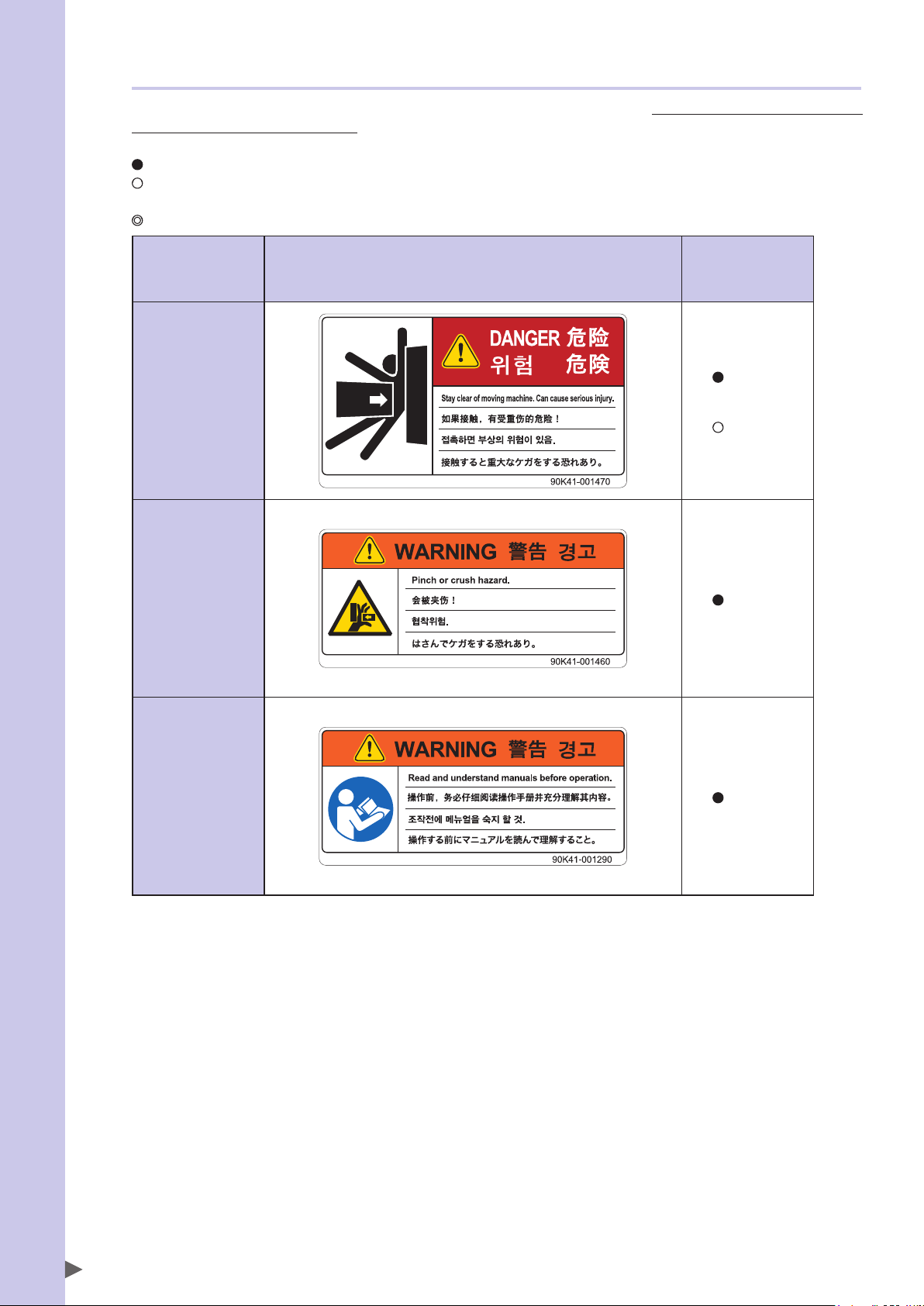
3.1.1 Warning label messages on robot and controller
Word messages on the danger, warning and caution labels are concise and brief instructions. For more specific
instructions, read and follow the "Instructions on this label" described on the right of each label shown below.
See “7.1 Movement range” for details on the robot’s movement range.
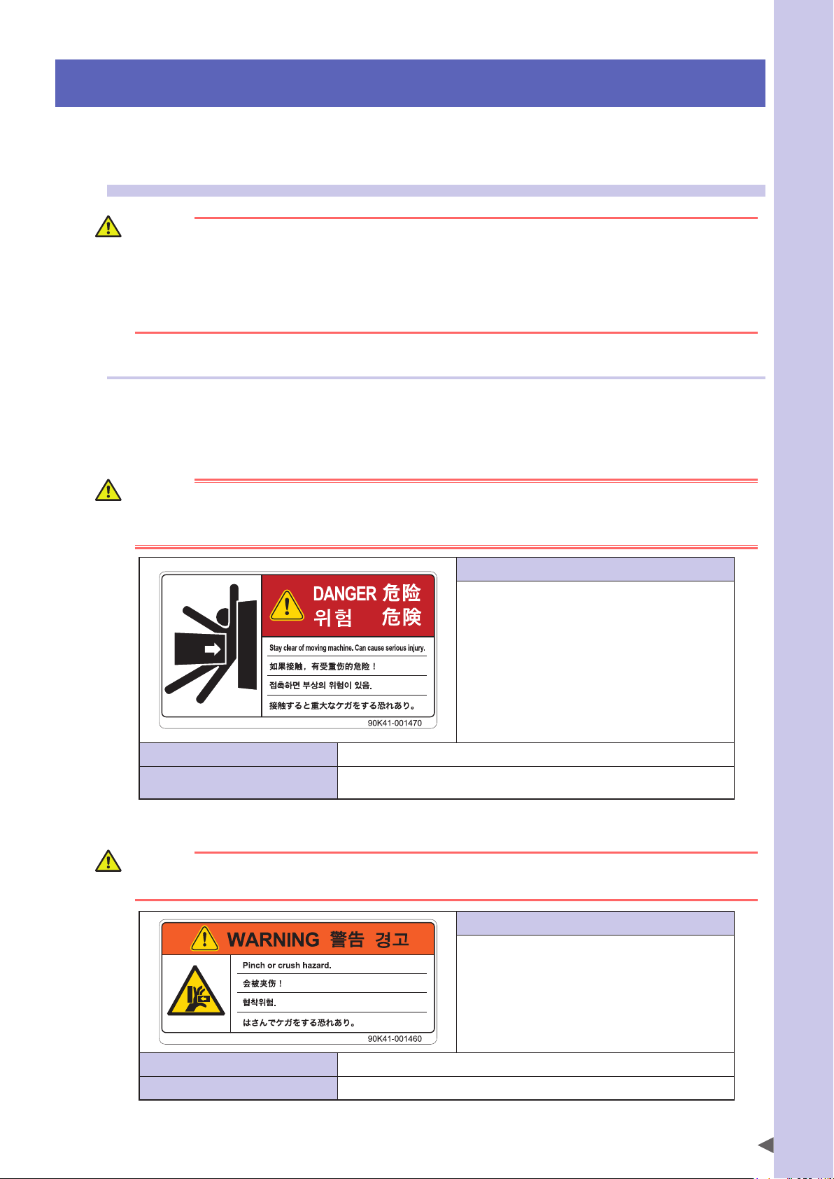
■Warning label 1
DANGER
Serious injury may result from contact with a moving robot.
• Keep outside of the robot safety enclosure during operation.
• Press the emergency stop button before entering the safety enclosure.
Safety Instructions
Potential hazard to human body
To avoid hazard
Serious injury may result from contact with a moving robot.
• Keep outside of the robot safety enclosure during operation.
• Press the emergency stop button before entering the safety enclosure.
■Warning label 2
WARNING
Moving parts can pinch or crush hands.
Keep hands away from the movable parts of the robot.
Instructions on this label
• Always install a safety enclosure to keep all persons
away from the robot movement range and prevent
injury from contacting the moving part of the robot.
Install an interlock that triggers emergency stop when
•
the door or gate of the safety enclosure is opened.
• The safety enclosure should be designed so that no
one can enter inside except from the door or gate
equipped with an interlock device.
• Warning label 1 that comes supplied with a robot
should be affixed to an easy-to-see location on the
door or gate of the safety enclosure.
90K41-001470
Instructions on this label
Use caution to prevent hands and fingers from being
pinched or crushed by the movable parts of the robot
when transporting or moving the robot or during
teaching.
Potential hazard to human body
To avoid hazard
Moving parts can pinch or crush hands.
Keep hands away from the movable parts of the robot.
90K41-001460
S-3
Page 16
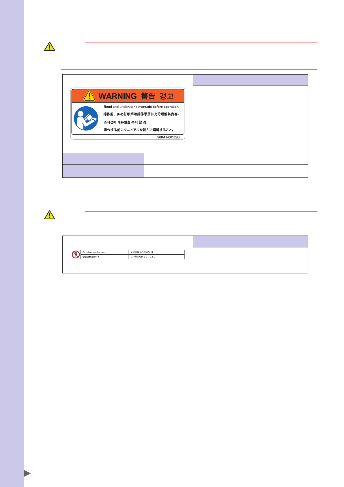
■Warning label 3
Safety Instructions
WARNING
Improper installation or operation may cause serious injury.
Before installing or operating the robot, read the manual and instructions on the warning labels and understand
the contents.
Instructions on this label
• Be sure to read the warning label and this manual
carefully to make you completely understand the
contents before attempting installation and operation
of the robot.
• Before starting the robot operation, even after you
have read through this manual, read again the
corresponding procedures and "Safety Instructions".
• Never install, adjust, inspect or service the robot in
any manner that does not comply with the
instructions in this manual.
Potential hazard to human body
To avoid hazard
Improper installation or operation may cause serious injury.
Before installing or operating the robot, read the manual and instructions on the
warning labels and understand the contents.
■Warning label 4
90K41-001290
CAUTION
Do not remove the parts on which Warning label 4 is attached.
Doing so may damage the ball screw.
Instructions on this label
The Z-axis ball screw will be damaged if the upper end
mechanical stopper on the Z-axis spline is removed or
moved. Never attempt to remove or move it.
90K41-001520
S-4
Page 17
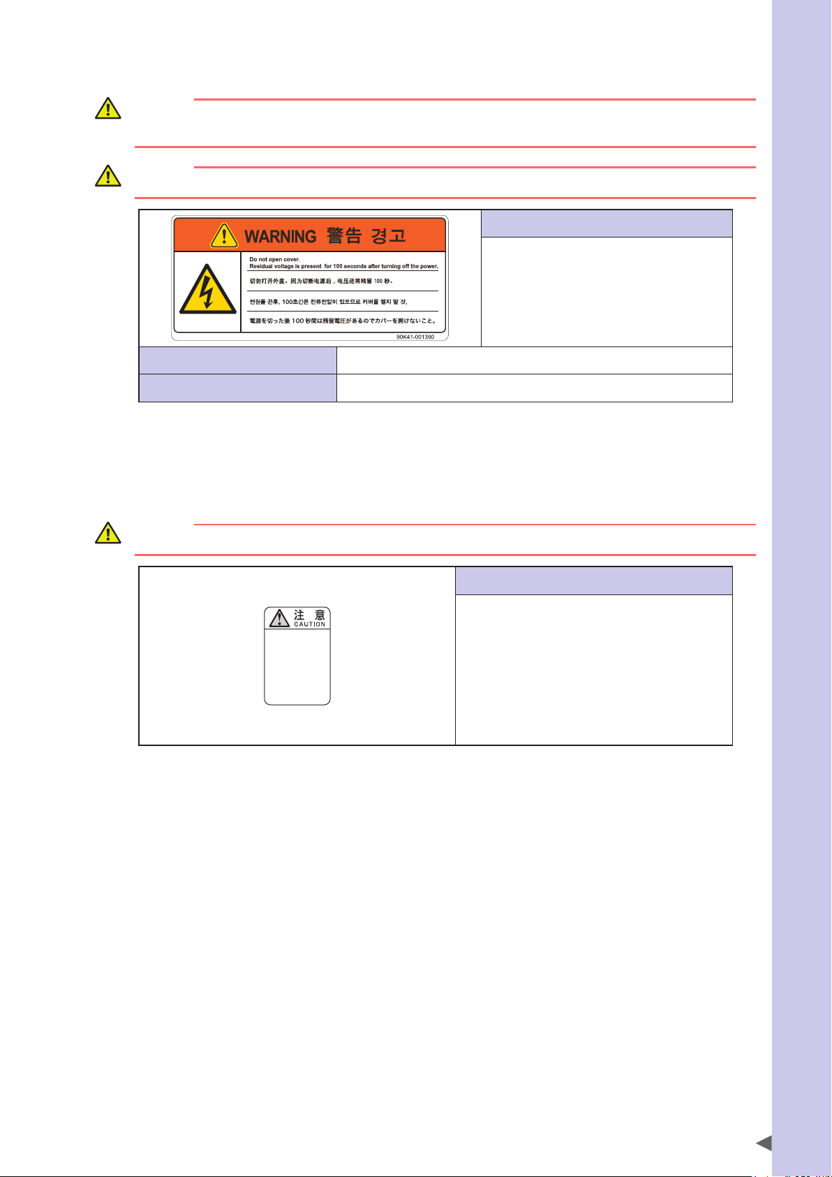
■Warning label 5 (YRCX/YRC controllers)
WARNING
These are precautions for OMRON and distributors' service personnel.
Customers must not attempt to open the covers.
WARNING
Wait at least 100 seconds after power-off before opening the covers.
Instructions on this label
• Wait at least 100 seconds after power-off
before opening the covers (*).
• Some parts in the controller still retain a high
voltage even after power-off, so electrical
shock may occur if those parts are touched.
Potential hazard to human body
To avoid hazard
Electrical shock
Wait at least 100 seconds after power-off before opening the covers (*).
* These are precautions for OMRON and distributors' service personnel. Customers must not attempt to open the covers.
90K41-001390
■Warning label 6 (Controller)*
* This label is attached to the front panel.
Safety Instructions
CAUTION
Refer to the manual.
取扱説明書参照
READ INSTRUCTION
MANUAL
Instructions on this label
This indicates important information that you must
know and is described in the manual.
Before using the controller, be sure to read the manual
thoroughly.
When adding external safety circuits or connecting a
power supply to the controller, read the manual
carefully and make checks before beginning the work.
Connectors have an orientation. Insert each connector
in the correct direction.
93005-X0-00
S-5
Page 18
3.1.2 Supplied warning labels
Safety Instructions
Some warning labels are not affixed to robots but included in the packing box. These warning labels should be
affixed to an easy-to-see location.
Warning label is attached to the robot body.
Warning label comes supplied with the robot and should be affixed to an easy-to-see location on the door or gate of the
safety enclosure.
Warning label comes supplied with the robot and should be affixed to an easy-to-see location.
SCARA robots
1
*
Warning label 1
Warning label 2
Warning label 3
*1: See "Part names" in each SCARA robot manual for label positions.
1
*
1
*
S-6
Page 19
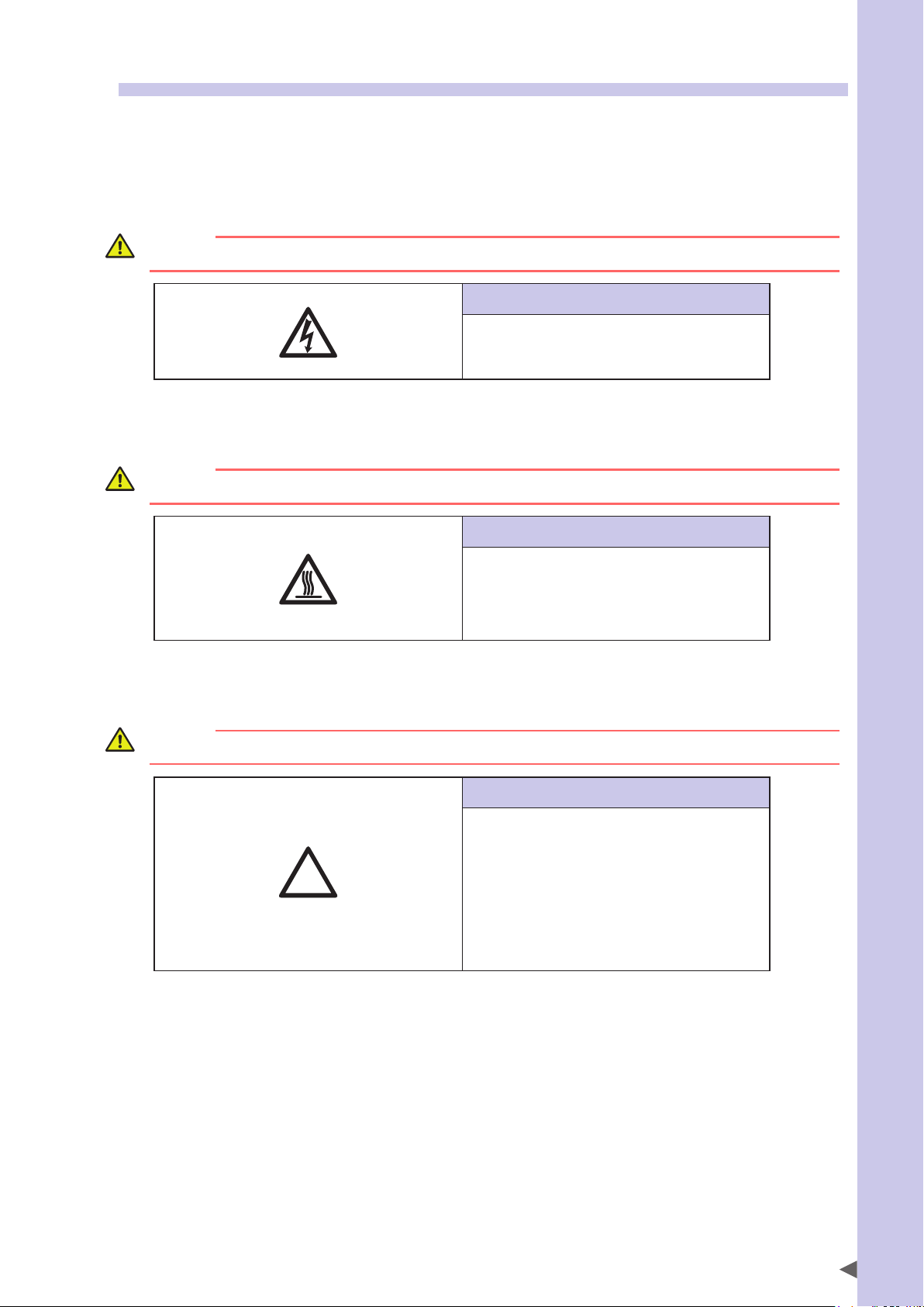
3.2 Warning symbols
!
Warning symbols shown below are indicated on the robots and controllers to alert the operator to potential
hazards. To use the OMRON robot safely and correctly always follow the instructions and cautions indicated
by the symbols.
1. Electrical shock hazard symbol
WARNING
Touching the terminal block or connector may cause electrical shock, so use caution.
Instructions by this symbol
This indicates a high voltage is present.
Touching the terminal block or connector may cause
electrical shock.
93006-X0-00
2. High temperature hazard symbol
WARNING
Motors, heatsinks, and regenerative units become hot, so do not touch them.
Instructions by this symbol
Safety Instructions
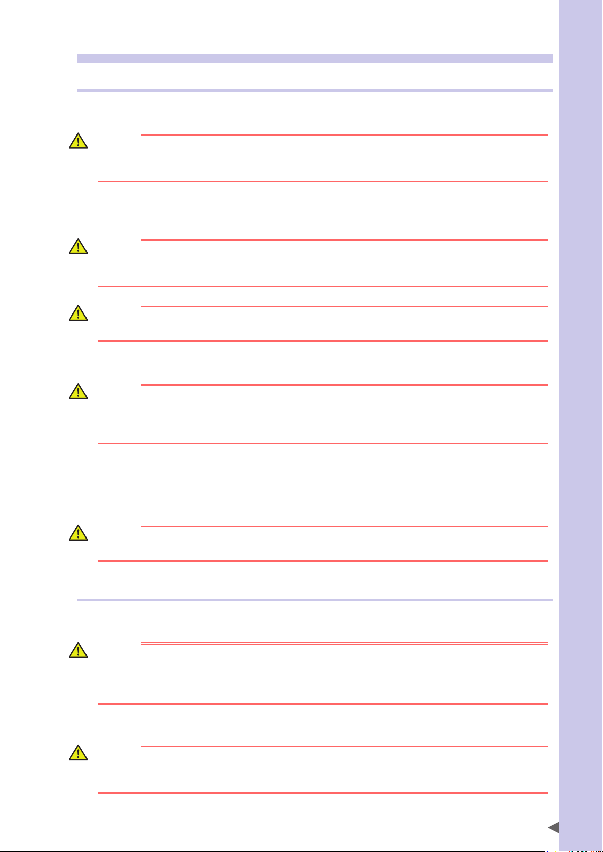
3. Caution symbol
CAUTION
Always read the manual carefully before using the controller.
This indicates the area around this symbol may become
very hot.
Motors, heatsinks, and regenerative units become hot
during and shortly after operation. To avoid burns be
careful not to touch those sections.
93008-X0-00
Instructions by this symbol
This indicates important information that you must
know and is described in the manual.
Before using the controller, be sure to read the manual
thoroughly.
When adding external safety circuits or connecting a
power supply to the controller, read the manual
carefully and make checks before beginning the work.
Connectors must be attached while facing a certain
direction, so insert each connector in the correct
direction.
93007-X0-00
S-7
Page 20

Safety Instructions
4. Important precautions for each stage of the robot life cycle
This section describes major precautions that must be observed when using robots and controllers. Be sure to
carefully read and comply with all of these precautions even if there is no alert symbol shown.
4.1 Precautions for using robots and controllers
General precautions for using robots and controllers are described below.
1. Applications where robots cannot be used
OMRON robots and robot controllers are designed as general-purpose industrial equipment and cannot be used for the
following applications.
DANGER
OMRON robot controllers and robots are designed as general-purpose industrial equipment and cannot be used
for the following applications.
• In medical equipment systems which are critical to human life
• In systems that significantly affect society and the general public
• In equipment intended to carry or transport people
• In environments which are subject to vibration such as onboard ships and vehicles.
2. Qualification of operators/workers
Operators or persons who perform tasks for industrial robots (such as teaching, programming, movement check, inspection, adjustment, and repair) must receive appropriate training and also have the skills needed to perform the tasks
correctly and safely.
Those tasks must be performed by qualified persons who meet requirements established by local regulations and standards for industrial robots. They must also read the manual carefully and understand its contents before attempting the
robot operation or maintenance.
WARNING
• It is extremely hazardous for persons who do not have the above qualifications to perform tasks for industrial
robots.
• Adjustment and maintenance that require removing a cover must be performed by persons who have the
above qualifications. Any attempt to perform such tasks by an unqualified person may cause an accident
resulting in serious injury or death.
S-8
Page 21
4.2 Design
4.2.1 Precautions for robots
1. Restricting the robot moving speed
WARNING
Restriction on the robot moving speed is not a safety-related function.
To reduce the risk of collision between the robot and workers, the user must take the necessary protective
measures such as enable devices according to risk assessment by the user.
2. Restricting the movement range
See “7.1 Movement range” for details on the robot’s movement range.
WARNING
Soft limit function is not a safety-related function intended to protect the human body.
To restrict the robot movement range to protect the human body, use the mechanical stoppers installed in the
robot (or available as options).
CAUTION
If the robot moving at high speed collides with a mechanical stopper installed in the robot (or available as
option), the robot may be damaged.
3. Provide safety measures for end effector (gripper, etc.)
Safety Instructions
WARNING
• End effectors must be designed and manufactured so that they cause no hazards (such as a loose workpiece
or load) even if power (electricity, air pressure, etc.) is shut off or power fluctuations occur.
• If the object gripped by the end effector might possibly fly off or drop, then provide appropriate safety
protection taking into account the object size, weight, temperature, and chemical properties.
4. Provide adequate lighting
Provide enough lighting to ensure safety during work.
5. Install an operation status light
WARNING
Install a signal light (signal tower) at an easy-to-see position so that the operator will be aware of the robot stop
status (temporarily stopped, emergency stop, error stop, etc.).
4.2.2 Precautions for robot controllers
1. Emergency stop input terminal
DANGER
Each robot controller has an emergency stop input terminal to trigger emergency stop. Using this terminal, install
a safety circuit so that the system including the robot controller will work safely.
For the robot driver without emergency stop input terminal, construct a safety circuit including the emergency
stop function using an external circuit.
2. Maintain clearance
CAUTION
Do not bundle control lines or communication cables together or in close to the main power supply or power
lines. Usually separate these by at least 100mm. Failure to follow this instruction may cause malfunction due to
noise.
S-9
Page 22
4.3 Moving and installation
Safety Instructions
4.3.1 Precautions for robots
■Installation environment
1. Do not use in strong magnetic fields
WARNING
Do not use the robot near equipment or in locations that generate strong magnetic fields. The robot may BREAK
DOWN or malfunction if used in such locations.
2. Do not use in locations subject to possible electromagnetic interference, etc.
WARNING
Do not use the robot in locations subject to electromagnetic interference, electrostatic discharge or radio
frequency interference. The robot may malfunction if used in such locations creating hazardous situations.
3. Do not use in locations exposed to flammable gases
WARNING
• OMRON robots are not designed to be explosion-proof.
• Do not use the robots in locations exposed to explosive or inflammable gases, dust particles or liquid. Failure to
follow this instruction may cause serious accidents involving injury or death, or lead to fire.
■Moving
1. Use caution to prevent pinching or crushing of hands or fingers
WARNING
Moving parts can pinch or crush hands or fingers.
Keep hands away from the movable parts of the robot.
As instructed in Warning label 2, use caution to prevent hands or fingers from being pinched or crushed by movable parts
when transporting or moving the robot. For details on warning labels, see "3. Warning labels".
2. Take safety measures when moving robots
To ensure safety when moving a SCARA robot with an arm length of 500mm or more, use the eyebolts that come supplied
with the robot. Always refer to the robot user’s manual for details.
When moving other robots, please comply with the transport methods described in their respective user’s manuals.
3. Take measures to prevent the robot from falling
When moving the robot by lifting it with equipment such as a hoist or crane, wear personal protective gear and be
careful not to move the robot at higher than the required height.
Make sure that there are no persons on paths used for moving the robot.
WARNING
A robot falling from a high place and striking a worker may cause death or serious injury. When moving the
robot, wear personal protective gear such as helmets and make sure that no one is within the surrounding area.
■Installation
1. Protect electrical wiring and hydraulic/pneumatic hoses
Install a cover or similar item to protect the electrical wiring and hydraulic/pneumatic hoses from possible damage.
S-10
Page 23

■Wiring
1. Protective measures against electrical shock
WARNING
Always ground the robot to prevent electrical shock.
■Adjustment
1. Adjustment that requires removing a cover
WARNING
Adjustment by removing a cover require specialized technical knowledge and skills, and may also involve
hazards if attempted by an unskilled person. This adjustment must be performed only by persons who have the
required qualifications described in “2. Qualification of operators/workers” in section 4.1 of this “Safety Instructions”.
4.3.2 Precautions for robot controllers
■Installation environment
1. Installation environment
WARNING
OMRON robots are not designed to be explosion-proof. Do not use the robots and controllers in locations
exposed to explosive or inflammable gases, dust particles or liquid such as gasoline and solvents. Failure to
follow this instruction may cause serious accidents involving injury or death, and lead to fire.
Safety Instructions
WARNING
• Use the robot controller in locations that support the environmental conditions specified in this manual.
Operation outside the specified environmental range may cause electrical shock, fire, malfunction or product
damage or deterioration.
• The robot controller and programming box must be installed at a location that is outside the robot safety
enclosure yet where it is easy to operate and view robot movement.
• Install the robot controller in locations with enough space to perform work (teaching, inspection, etc.) safely.
Limited space not only makes it difficult to perform work but can also cause injury.
• Install the robot controller in a stable, level location and secure it firmly. Avoid installing the controller upside
down or in a tilted position.
• Provide sufficient clearance around the robot controller for good ventilation. Insufficient clearance may cause
malfunction, breakdown or fire.
■Installation
To install the robot controller, observe the installation conditions and method described in the manual.
1. Installation
WARNING
Securely tighten the screws to install the robot controller. If not securely tightened, the screws may come loose
causing the controller to drop.
2. Connections
WARNING
• Always shut off all phases of the power supply externally before starting installation or wiring work. Failure to do
this may cause electrical shock or product damage.
• Never directly touch conductive sections and electronic parts other than the connectors, rotary switches, and
DIP switches on the outside panel of the robot controller. Touching them may cause electrical shock or
breakdown.
• Securely install each cable connector into the receptacles or sockets. Poor connections may cause the
controller or robot to malfunction.
S-11
Page 24
■Wiring
Safety Instructions
1. Connection to robot controller
The controller parameters are preset at the factory before shipping to match the robot model. Check the specified robot
and controller combination, and connect them in the correct combination.
Since the software detects abnormal operation such as motor overloads, the controller parameters must be set correctly
to match the motor type used in the robot connected to the controller.
2. Wiring safety points
WARNING
Always shut off all phases of the power supply externally before starting installation or wiring work. Failure to do
this may cause electrical shock or product damage.
CAUTION
• Make sure that no foreign matter such as cutting chips or wire scraps get into the robot controller. Malfunction,
breakdown or fire may result if these penetrate inside.
• Do not apply excessive impacts or loads to the connectors when making cable connections. This might bend
the connector pins or damage the internal PC board.
• When using ferrite cores for noise elimination, be sure to fit them onto the power cable as close to the robot
controller and/or the robot as possible, to prevent malfunction caused by noise.
3. Wiring method
WARNING
Securely install the connectors into the robot controller and, when wiring the connectors, make the crimp,
press-contact or solder connections correctly using the tool specified by the connector manufacturer.
CAUTION
When disconnecting the cable from the robot controller, detach by gripping the connector itself and not by
tugging on the cable. Loosen the screws on the connector (if fastened with the screws), and then disconnect the
cable. Trying to detach by pulling on the cable itself may damage the connector or cables, and poor cable
contact will cause the controller or robot to malfunction.
4. Precautions for cable routing and installation
CAUTION
• Always store the cables connected to the robot controller in a conduit or clamp them securely in place. If the
cables are not stored in a conduit or properly clamped, excessive play or movement or mistakenly pulling on
the cable may damage the connector or cables, and poor cable contact will cause the controller or robot to
malfunction.
• Do not modify the cables and do not place any heavy objects on them. Handle them carefully to avoid
damage. Damaged cables may cause malfunction or electrical shock.
• If the cables connected to the robot controller may possibly become damaged, then protect them with a
cover, etc.
• Check that the control lines and communication cables are routed at a gap sufficiently away from main power
supply circuits and power lines, etc. Bundling them together with power lines or close to power lines may
cause faulty operation due to noise.
5. Protective measures against electrical shock
WARNING
Be sure to ground the ground terminals of the robot and controller. Poor grounding may cause electrical shock.
S-12
Page 25
4.4 Safety measures
4.4.1 Safety measures
1. Referring to warning labels and manual
WARNING
• Before starting installation or operation of the robot, be sure to read the warning labels and this manual, and
comply with the instructions.
• Never attempt any repair, parts replacement and modification unless described in this manual. These
tasks require specialized technical knowledge and skills and may also involve hazards. Please contact your
distributor for advice.
NOTE
For details on warning labels, see "3. Warning labels".
2. Draw up "work instructions" and make the operators/workers understand them
WARNING
Decide on "work instructions" in cases where personnel must work within the robot safety enclosure to perform
startup or maintenance work. Make sure the workers completely understand these "work instructions".
Decide on "work instructions" for the following items in cases where personnel must work within the robot safety
enclosure to perform teaching, maintenance or inspection tasks. Make sure the workers completely understand these
"work instructions".
1. Robot operating procedures needed for tasks such as startup procedures and handling switches
2. Robot speeds used during tasks such as teaching
3. Methods for workers to signal each other when two or more workers perform tasks
4. Steps that the worker should take when a problem or emergency occurs
5. Steps to take after the robot has come to a stop when the emergency stop device was triggered, including checks for
cancelling the problem or error state and safety checks in order to restart the robot.
6. In cases other than above, the following actions should be taken as needed to prevent hazardous situations due to
sudden or unexpected robot operation or faulty robot operation as listed below.
• Place a display sign on the operator panel
• Ensure the safety of workers performing tasks within the robot safety enclosure
• Clearly specify position and posture during work
Specify a position and posture where worker can constantly check robot movements and immediately move to
avoid trouble if an error/problem occurs
• Take noise prevention measures
• Use methods for signaling operators of related equipment
• Use methods to decide that an error has occurred and identify the type of error
Implement the "work instructions" according to the type of robot, installation location, and type of work task.
When drawing up the "work instructions", make an effort to include opinions from the workers involved, equipment
manufacturer technicians, and workplace safety consultants, etc.
Safety Instructions
3. Take safety measures
DANGER
• Never enter the robot movement range while the robot is operating or the main power is turned on. Failure to
follow this warning may cause serious accidents involving injury or death. Install a safety enclosure or a gate
interlock with an area sensor to keep all persons away from the robot movement range.
• When it is necessary to operate the robot while you are within the robot movement range such as for teaching
or maintenance/inspection tasks, always carry the programming box with you so that you can immediately
stop the robot operation in case of an abnormal or hazardous condition. Install an enable device in the
external safety circuit as needed. Also set the robot moving speed to 3% or less. Failure to follow these
instructions may cause serious accidents involving injury or death.
See “7.1 Movement range” for details on the robot’s movement range.
S-13
Page 26
Safety Instructions
WARNING
• During startup or maintenance tasks, display a sign "WORK IN PROGRESS" on the programming box and
operation panel in order to prevent anyone other than the person for that task from mistakenly operating the
start or selector switch. If needed, take other measures such as locking the cover on the operation panel.
• Always connect the robot and robot controller in the correct combination. Using them in an incorrect
combination may cause fire or breakdown.
4. Install system
When configuring an automated system using a robot, hazardous situations are more likely to occur from the automated
system than the robot itself. So the system manufacturer should install the necessary safety measures required for the
individual system. The system manufacturer should provide a proper manual for safe, correct operation and servicing of
the system.
WARNING
To check the robot controller operating status, refer to this manual and to related manuals. Design and install the
system including the robot controller so that it will always work safely.
5. Precautions for operation
WARNING
• Do not touch any electrical terminal. Directly touching these terminals may cause electrical shock, equipment
damage, and malfunction.
• Do not touch or operate the robot controller or programming box with wet hands. Touching or operating them
with wet hands may result in electrical shock or breakdown.
6. Do not disassemble and modify
WARNING
Never disassemble and modify any part in the robot, controller, and programming box. Do not open any cover.
Doing so may cause electrical shock, breakdown, malfunction, injury, or fire.
4.4.2 Installing a safety enclosure
Be sure to install a safety enclosure to keep anyone from entering within the movement range of the robot. The
safety enclosure will prevent the operator and other persons from coming in contact with moving parts of the
robot and suffering injury.
See “7.1 Movement range” for details on the robot’s movement range.
DANGER
Serious injury may result from contact with a moving robot.
• Keep outside of the robot safety enclosure during operation.
• Press the emergency stop button before entering the safety enclosure.
WARNING
• Install an interlock that triggers emergency stop when the door or gate of the safety enclosure is opened.
• The safety enclosure should be designed so that no one can enter inside except from the door or gate
equipped with an interlock device.
• Warning label 1 (See "3. Warning labels") that comes supplied with a robot should be affixed to an easy-to-see
location on the door or gate of the safety enclosure.
S-14
Page 27
4.5 Operation
When operating a robot, ignoring safety measures and checks may lead to serious accidents. Always take the
following safety measures and checks to ensure safe operation.
DANGER
Check the following points before starting robot operation.
• No one is within the robot safety enclosure.
• The programming unit is in the specified location.
• The robot and peripheral equipment are in good condition.
4.5.1 Trial operation
After installing, adjusting, inspecting, maintaining or repairing the robot, perform trial operation using the
following procedures.
1. If a safety enclosure has not yet been provided right after installing the robot:
Then rope off or chain off the movement range around the robot in place of the safety enclosure and observe the
following points.
See “7.1 Movement range” for details on the robot’s movement range.
DANGER
Place a "Robot is moving - KEEP AWAY!" sign to keep the operator or other personnel from entering within the
movement range of the robot.
Safety Instructions
WARNING
• Use sturdy, stable posts which will not fall over easily.
• The rope or chain should be easily visible to everyone around the robot.
2. Check the following points before turning on the controller.
• Is the robot securely and correctly installed?
• Are the electrical connections to the robot wired correctly?
• Are items such as air pressure correctly supplied?
• Is the robot correctly connected to peripheral equipment?
• Have safety measures (safety enclosure, etc.) been taken?
• Does the installation environment meet the specified standards?
3. After the controller is turned on, check the following points from outside the safety enclosure.
• Does the robot start, stop and enter the selected operation mode as intended?
• Does each axis move as intended within the soft limits?
• Does the end effector move as intended?
• Are the correct signals being sent to the end effector and peripheral equipment?
• Does emergency stop function?
• Are teaching and playback functions normal?
• Are the safety enclosure and interlocks functioning as intended?
S-15
Page 28
4. Working inside safety enclosures
Safety Instructions
Before starting work within the safety enclosure, always confirm from outside the enclosure that each protective
function is operating correctly (see the previous section 2.3).
DANGER
Never enter within the movement range while within the safety enclosure.
See “7.1 Movement range” for details on the robot’s movement range.
WARNING
When work is required within the safety enclosure, place a sign "Work in progress" in order to keep other persons
from operating the controller switch or operation panel.
WARNING
When work within the safety enclosure is required, always turn off the controller power except for the following
cases:
Exception
Work with power turned on, but robot in emergency stop
Origin position setting SCARA robots
Standard coordinate setting SCARA robots
Soft limit settings SCARA robots
Follow the precautions and procedure described in "Adjusting the
origin".
Follow the precautions and procedure described in "Setting the
standard coordinates".
Follow the precautions and procedure described in "Setting the soft
limits".
Work with power turned on
Teaching SCARA robots
Refer to "5. Teaching within safety enclosure" described below.
5. Teaching within the safety enclosure
When performing teaching within the safety enclosure, check or perform the following points from outside the safety
enclosure.
DANGER
Never enter within the movement range while within the safety enclosure.
See “7.1 Movement range” for details on the robot’s movement range.
WARNING
• Make a visual check to ensure that no hazards are present within the safety enclosure.
• Check that the programming box or handy terminal operates correctly.
• Check that no failures are found in the robot.
• Check that emergency stop works correctly.
• Select teaching mode and disable automatic operation.
S-16
Page 29
4.5.2 Automatic operation
Check the following points when operating the robot in AUTO mode. Observe the instructions below in cases
where an error occurs during automatic operation. Automatic operation described here includes all operations
in AUTO mode.
1. Checkpoints before starting automatic operation
Check the following points before starting automatic operation.
DANGER
• Check that no one is within the safety enclosure.
• Check the safety enclosure is securely installed with interlocks functional.
WARNING
• Check that the programming box / handy terminal and tools are in their specified locations.
• Check that the signal tower lamps or other alarm displays installed for the system are not lit or flashing,
indicating no error is occurring on the robot and peripheral devices.
2. During automatic operation and when errors occur
After automatic operation starts, check the operation status and the signal tower to ensure that the robot is in automatic
operation.
DANGER
Never enter the safety enclosure during automatic operation.
Safety Instructions
WARNING
If an error occurs in the robot or peripheral equipment, observe the following procedure before entering the
safety enclosure.
1) Press the emergency stop button to set the robot to emergency stop.
2) Place a sign on the start switch, indicating that the robot is being inspected in order to keep other persons from
restarting the robot.
4.5.3 Precautions during operation
1. When the robot is damaged or an abnormal condition occurs
WARNING
• If unusual odors, noise or smoke occur during operation, immediately turn off power to prevent possible
electrical shock, fire or breakdown. Stop using the robot and contact your distributor.
• If any of the following damage or abnormal conditions occurs the robot, then continuing to operate the robot
is dangerous. Immediately stop using the robot and contact your distributor.
Damage or abnormal condition Type of danger
Damage to machine harness or robot cable Electrical shock, robot malfunction
Damage to robot exterior Damaged parts fly off during robot operation
Abnormal robot operation (position deviation, vibration, etc.) Robot malfunction
Z-axis (vertical axis) or brake malfunction Z-axis unit falls off
2. High temperature hazard
WARNING
• Do not touch the robot controller and robot during operation. The robot controller and robot body are very hot
during operation, so burns may occur if these sections are touched.
• The motor and speed reduction gear casing are very hot shortly after operation, so burns may occur if these
are touched. Before touching those parts for inspections or servicing, turn off the controller, wait for a while and
check that their temperature has cooled.
S-17
Page 30
3. Use caution when releasing the Z-axis (vertical axis) brake
Safety Instructions
WARNING
The vertical axis will slide downward when the brake is released, causing a hazardous situation. Take adequate
safety measures in consideration by taking the weight and shape into account.
• Before releasing the brake after pressing the emergency stop button, place a support under the vertical axis so
that it will not slide down.
• Be careful not to let your body get caught between the vertical axis and the installation base when performing
tasks (direct teaching, etc.) with the brake released.
4. Be careful of Z-axis movement when the controller is turned off or emergency stop is triggered
(air-driven Z-axis)
WARNING
The Z-axis starts moving upward when power to the controller or PLC is turned off, the program is reset, emergency stop is triggered, or air is supplied to the solenoid valve for the Z-axis air cylinder.
• Do not let hands or fingers get caught and squeezed by robot parts moving along the Z-axis.
• Keep the usual robot position in mind so as to prevent the Z-axis from hanging up or binding on obstacles
during raising of the Z-axis except in case of emergency stop.
5. Take protective measures when the Z-axis interferes with peripheral equipment (air-driven Z-axis)
WARNING
When the Z-axis comes to a stop due to obstruction from peripheral equipment, the Z-axis may move suddenly
after the obstruction is removed, causing injury such as pinched or crushed hands.
• Turn off the controller and reduce the air pressure before attempting to remove the obstruction.
• Before reducing the air pressure, place a support under the Z-axis because the Z-axis will drop under its own
weight.
6. Be careful of Z-axis movement when air supply is stopped (air-driven Z-axis)
WARNING
The Z-axis will slide downward when the air pressure to the Z-axis air cylinder solenoid valve is reduced, creating
a hazardous situation.
Turn off the controller and place a support under the Z-axis before cutting off the air supply.
7. Make correct parameter settings
CAUTION
The robot must be operated with the correct tolerable moment of inertia and acceleration coefficients that
match the manipulator tip mass and moment of inertia. Failure to follow this instruction will lead to a premature
end to the drive unit service life, damage to robot parts, or cause residual vibration during positioning.
8. If the X-axis, Y-axis or R-axis rotation angle is small
CAUTION
If the X-axis, Y-axis or R-axis rotation angle is set smaller than 5 degrees, then it will always move within the same
position. This restricted position makes it difficult for an oil film to form on the joint support bearing, and so may
possibly damage the bearing. In this type of operation, add a range of motion so that the joint moves through 90
degrees or more, about 5 times a day.
S-18
Page 31

4.6 Inspection and maintenance
Always perform daily and periodic inspections and make a pre-operation check to ensure there are no problems with the robot and related equipment. If a problem or abnormality is found, then promptly repair it or
take other measures as necessary.
Keep a record of periodic inspections or repairs and store this record for at least 3 years.
4.6.1 Before inspection and maintenance work
1. Do not attempt any work or operation unless described in this manual.
Never attempt any work or operation unless described in this manual.
If an abnormal condition occurs, please be sure to contact your distributor. Our service personnel will take appropriate
action.
WARNING
Never attempt inspection, maintenance, repair, and part replacement unless described in this manual. These
tasks require specialized technical knowledge and skills and may also involve hazards. Please be sure to
contact your distributor for advice.
2. Precautions during repair and parts replacement
WARNING
When it is necessary to repair or replace parts of the robot or controller, please be sure to contact your distributor
and follow the instructions they provide. Inspection and maintenance of the robot or controller by an unskilled,
untrained person is extremely hazardous.
Safety Instructions
Adjustment, maintenance and parts replacement require specialized technical knowledge and skills, and also may
involve hazards. These tasks must be performed only by persons who have enough ability and qualifications required by
local laws and regulations.
WARNING
Adjustment and maintenance by removing a cover require specialized technical knowledge and skills, and may
also involve hazards if attempted by an unskilled person. This adjustment must be performed only by persons
who have the required qualifications described in “2. Qualification of operators/workers” in section 4.1 of this
“Safety Instructions”.
3. Shut off all phases of power supply
WARNING
Always shut off all phases of the power supply externally before cleaning the robot and controller or securely
tightening the terminal screws etc. Failure to do this may cause electrical shock or product damage or malfunction.
4. Allow a waiting time after power is shut off (Allow time for temperature and voltage to drop)
WARNING
• When performing maintenance or inspection of the robot controller under your distributor's instructions, wait at
least the time (*) specified for each controller after turning the power off. Some components in the robot
controller are very hot or still retain a high voltage shortly after operation, so burns or electrical shock may
occur if those parts are touched.
• The motor and speed reduction gear casing are very hot shortly after operation, so burns may occur if they are
touched. Before touching those parts for inspections or servicing, turn off the controller, wait for a while and
check that the temperature has cooled.
* For information on how long you should wait after turning the power off, see the user’s manual for each controller.
5. Precautions during inspection of controller
WARNING
• When you need to touch the terminals or connectors on the outside of the controller during inspection, always
first turn off the controller power switch and also the power source in order to prevent possible electrical shock.
• Do not disassemble the controller. Never touch any internal parts of the controller. Doing so may cause
breakdown, malfunction, injury, or fire.
S-19
Page 32

4.6.2 Precautions during service work
Safety Instructions
1. Be careful when removing the Z-axis motor
WARNING
The Z-axis will slide downward when the Z-axis motor is removed, causing a hazardous situation.
• Turn off the controller and place a support under the Z-axis before removing the Z-axis motor.
• Be careful not to let your body get caught by the driving unit of the Z-axis or between the Z-axis drive unit and
the installation base.
2. Do not remove the Z-axis upper limit mechanical stopper
CAUTION
Warning label 4 is attached to each SCARA robot. (For details on warning labels, see "3. Warning labels".)
Removing the upper limit mechanical stopper installed to the Z-axis spline or shifting its position will damage the
Z-axis ball screw. Never attempt to remove it.
3. Use caution when handling a robot that contains powerful magnets
WARNING
Powerful magnets are installed inside the robot. Do not disassemble the robot since this may cause injury.
Devices that may malfunction due to magnetic fields must be kept away from this robot.
See "6. Cautions regarding strong magnetic fields" for detailed information on strong magnetic fields.
4. Use the following caution items when disassembling or replacing the pneumatic equipment.
WARNING
Air or parts may fly outward if pneumatic equipment is disassembled or parts replaced while air is still supplied.
• Do service work after turning off the controller, reducing the air pressure, and exhausting the residual air from
the pneumatic equipment.
• Before reducing the air pressure, place a support stand under the Z-axis (2-axis robots with air driven Z-axis)
since it will drop under its own weight.
5. Use caution to avoid contact with the controller cooling fan
WARNING
• Touching the rotating fan may cause injury.
• If removing the fan cover, first turn off the controller and make sure the fan has stopped.
6. Precautions for robot controllers
CAUTION
• Back up the robot controller internal data on an external storage device. The robot controller internal data
(programs, point data, etc.) may be lost or deleted for unexpected reasons. Always make a backup of this data.
• Do not use thinner, benzene, or alcohol to wipe off the surface of the programming box. The surface sheet may
be damaged or printed letters or marks erased. Use a soft, dry cloth and gently wipe the surface.
• Do not use a hard or pointed object to press the keys on the programming box. Malfunction or breakdown
may result if the keys are damaged. Use your fingers to operate the keys.
S-20
Page 33

4.7 Disposal
When disposing of robots and related items, handle them carefully as industrial wastes. Use the correct
disposal method in compliance with your local regulations, or entrust disposal to a licensed industrial waste
disposal company.
1. Disposal of lithium batteries
When disposing of lithium batteries, use the correct disposal method in compliance with your local regulations, or
entrust disposal to a licensed industrial waste disposal company. We do not collect and dispose of the used batteries.
2. Disposal of packing boxes and materials
When disposing of packing boxes and materials, use the correct disposal method in compliance with your local regulations. We do not collect and dispose of the used packing boxes and materials.
3. Strong magnet
WARNING
Strong magnets are installed in the robot. Be careful when disposing of the robot.
See "6. Cautions regarding strong magnetic fields" for detailed information on strong magnetic fields.
Safety Instructions
S-21
Page 34

Safety Instructions
5. Emergency action when a person is caught by robot
If a person should get caught between the robot and a mechanical part such as the installation base, then
release the axis.
■Emergency action
Release the axis while referring to the following section in the manual for the robot controller.
Controller Refer to:
YRC
Section 1, "Emergency action when a person is caught by robot" in Chapter 1
YRCX
NOTE
Make a printout of the relevant page in the manual and post it a conspicuous location near the controller.
6. Cautions regarding strong magnetic fields
Some OMRON robots contain parts generating strong magnetic fields which may cause bodily injury, death,
or device malfunction. Always comply with the following instructions.
• Persons wearing ID cards, purses or wristwatches must keep away from the robot.
• Do not bring tools close to the magnet inside the robot.
S-22
Page 35

7. Using the robot safely
7.1 Movement range
When a tool or workpiece is attached to the robot manipulator tip, the actual movement range enlarges from
the movement range of the robot itself (Figure A) to include the areas taken up by movement of the tool and
workpiece attached to the manipulator tip (Figure B).
The actual movement range expands even further if the tool or workpiece is offset from the manipulator tip.
The movement range here is defined as the range of robot motion including all areas through which the robot
arms, the tool and workpiece attached to the manipulator tip, and the solenoid valves attached to the robot
arms move.
To make the robot motion easier to understand, the figures below only show the movement ranges of the tool
attachment section, tool, and workpiece.
Please note that during actual operation, the movement range includes all areas where the robot arms and any
other parts move along with the robot.
Movement range
Safety Instructions
Figure A: Movement range of robot itself
CAUTION
To make the robot motion easier to understand, the above figures only show the movement ranges of the tool
attachment section, tool, and workpiece. In actual operation, the movement range includes all areas where the
robot arms and any other parts move along with the robot.
Figure B: Movement range when tool and workpiece are attached
to manipulator tip
93009-X0-00
S-23
Page 36

7.2 Robot protective functions
Safety Instructions
Protective functions for OMRON robots are described below.
1. Overload detection
This function detects an overload applied to the motor and turns off the servo.
If an overload error occurs, take the following measures to avoid such errors:
1. Insert a timer in the program.
2. Reduce the acceleration.
2. Overheat detection
This function detects an abnormal temperature rise in the driver inside the controller and turns off the servo.
If an overheat error occurs, take the following measures to avoid the error:
1. Insert a timer in the program.
2. Reduce the acceleration.
3. Soft limits
Soft limits can be set on each axis to limit the working envelope in manual (jog) operation and automatic operation after
return-to-origin. The working envelope is the area limited by soft limits.
WARNING
Soft limit function is not a safety-related function intended to protect the human body.
To restrict the robot movement range to protect the human body, use the mechanical stoppers installed in the
robot (or available as options).
4. Mechanical stoppers
If the servo is turned off by emergency stop operation or protective function while the robot is moving, then these
mechanical stoppers prevent the axis from exceeding the movement range. The movement range is the area limited by the
mechanical stoppers.
• The X and Y axes have mechanical stoppers that are installed at both ends of the maximum movement
range. Some robot models have a standard feature that allows changing the mechanical stopper
SCARA robots
positions. On some other models, the mechanical stopper positions can also be changed by using
option parts.
• The Z-axis has a mechanical stopper at the upper end and lower end. The stopper positions can be
changed by using option parts.
• No mechanical stopper is provided on the R-axis.
WARNING
Axis movement does not stop immediately after the servo is turned off by emergency stop or other protective
functions, so use caution.
CAUTION
If the robot moving at high speed collides with a mechanical stopper installed in the robot (or available as
option), the robot may be damaged.
5. Z-axis (vertical axis) brake
An electromagnetic brake is installed on the Z-axis to prevent the Z-axis from sliding downward when the servo is OFF.
This brake is working when the controller is OFF or the Z-axis servo power is OFF even when the controller is ON. The
Z-axis brake can be released by the programming unit / handy terminal or by a command in the program when the
controller is ON.
WARNING
The vertical axis will slide downward when the brake is released, causing a hazardous situation. Take adequate
safety measures in consideration by taking the weight and shape into account.
•
Before releasing the brake after pressing the emergency stop button, place a support under the vertical axis so
that it will not slide down.
•
Be careful not to let your body get caught between the vertical axis and the installation base when performing
tasks (direct teaching, etc.) with the brake released.
S-24
Page 37

7.3 Residual risk
To ensure safe and correct use of OMRON robots and controllers, System integrators and/or end users implement machinery safety design that conforms to ISO12100.
Residual risks for OMRON robots and controllers are described in the DANGER or WARNING instructions
provided in each chapter and section. Read them carefully.
7.4 Special training for industrial robot operation
Operators or persons who handle the robot for tasks such as for teaching, programming, movement checks,
inspections, adjustments, and repairs must receive appropriate training and also have the skills needed to
perform the job correctly and safely. They must also read the manual carefully to understand its contents before
attempting the robot operation or maintenance.
Tasks related to industrial robots (teaching, programming, movement check, inspection, adjustment, repair,
etc.) must be performed by qualified persons who meet requirements established by local regulations and
safety standards for industrial robots.
Safety Instructions
Comparison of terms used in this manual with ISO
This manual ISO 10218-1 Note
Maximum movement range
Movement range
Working envelope
Within safety enclosure
See “7.1 Movement range” in for details on the robot’s movement range.
maximum space Area limited by mechanical stoppers.
restricted space Area limited by movable mechanical stoppers.
operational space Area limited by software limits.
safeguarded space
S-25
Page 38

7.5 KC mark
Safety Instructions
KC (Korean Certification) is a system based on the Korean Radio Law. Machineries designated with this system
are required to be registered as conformed certification or conformed registration, and to show KC marks.
Target products are prescribed by notification of the National Radio Research Agency (RRA).
7.5.1 EMC standards
■Cautions regarding compliance with KC mark
The OMRON robot-series product is one component that is incorporated into the customer's system (built-in equipment).
We decide models by single robot product (controller, robot and peripheral device) and conform them to the EMC
standards.
This does not therefore guarantee that the OMRON robot-series product conforms to the EMC standards if only the robot
is used independently. The customer who incorporates OMRON robot products into the customer's final system, which
will be shipped to or used in Korea, should verify that the overall system conforms to the EMC standards.
■KC mark
The OMRON robots (robots and controllers) are registered in the National Radio Research Agency (RRA) as conformed by
self-test and KC marks are affixed to the robots.
■Related standards
• Electromagnetic Compatibility (EMC)
■Information of conformity assessment
• Certification number list
Product Model name Certification number
Controller
Robot
• Applicant and manufacturer : OMRON
YRC MSIP-REM-Y3M-X240
YRCX MSIP-REM-Y3M-X340
SCARA robots MSIP-REM-Y3M-YK
7.5.2 Examples of EMC countermeasures
It is not necessary to take measures for ERCD and robots connecting to ERCD.
Examples of EMC countermeasures for single OMRON robot product are the same as those of CE marks.
Refer to countermeasures described in the related user's manual.
Furthermore, take proper countermeasures to conform customer's final system (overall system) to EMC
standards.
S-26
Page 39

Warranty
The OMRON robot and/or related product you have purchased are warranted against the defects or
malfunctions as described below.
■Warranty description
If a failure or breakdown occurs due to defects in materials or workmanship in the genuine parts constituting this
OMRON robot and/or related product within the warranty period, then OMRON shall supply free of charge the necessary
replacement/repair parts.
■Warranty period
The warranty period ends 24 months after the date of manufacturing as shown on the products.
■Exceptions to the warranty
This warranty will not apply in the following cases:
1. Fatigue arising due to the passage of time, natural wear and tear occurring during operation (natural fading of painted
or planted surfaces, deterioration of parts subject to wear, etc.)
2. Minor natural phenomena that do not affect the capabilities of the robot and/or related product (noise from computers,
motors, etc.)
3. Programs, point data and other internal data were changed or created by the user.
Warranty
Failures resulting from the following causes are not covered by warranty.
1. Damage due to earthquakes, storms, floods, thunderbolt, fire or any other natural or man-made disaster.
2. Troubles caused by procedures prohibited in this manual.
3. Modifications to the robot and/or related product not approved by OMRON or OMRON sales representative.
4. Use of any other than genuine parts and specified grease and lubricant.
5. Incorrect or inadequate maintenance and inspection.
6. Repairs by other than authorized dealers.
WARRANTY
OMRON's exclusive warranty is that the products are free from defects in materials and workmanship
for a period of one year (or other period if specified) from date of sale by OMRON. OMRON MAKES
NO WARRANTY OR REPRESENTATION, EXPRESS OR IMPLIED, REGARDING NONINFRINGEMENT,
MERCHANTABILITY, OR FITNESS FOR PARTICULAR PURPOSE OF THE PRODUCTS. ANY BUYER OR
USER ACKNOWLEDGES THAT THE BUYER OR USER ALONE HAS DETERMINED THAT THE PRODUCTS
WILL SUITABLY MEET THE REQUERIMENTS OF THEIR INTENDED USE. OMRON DISCLAIMS ALL OTHER
WARRANTIES, EXPRESS OR IMPLIED.
LIMITATIONS OF LIABILITY
OMRON SHALL NOT BE RESPONSIBLE FOR SPECIAL, INDIRECT OR CONSEQUENTIAL DAMAGES, LOSS
OF PROFITS OR COMERCIAL LOSS IN ANY WAY CONNECTED WITH THE PRODUCTS, WETHER SUCH
CLAIM IS BASED ON CONTRACT, WARRANTY, NEGLIGENCE OR STRICT LIABILITY.
In no event shall the responsibility of OMRON for any act exceed the individual price of the product on
which liability is asserted.
IN NO EVENT SHALL OMRON BE RESPONSIBLE FOR WARRANTY, REPAIR OR OTHER CLAIMS REGARDING
THE PRODUCTS UNLESS OMRON'S ANALYSIS CONFIRMS THAT THE PRODUCTS WERE PROPERLY
HANDLED, STORED, INSTALLED AND MAINTAINED AND NOT SUBJECT TO CONTAMINATION, ABUSE,
MISUSE OR INAPPROPIATE MODIFICATION OR REPAIR.
Page 40

Page 41

Important information before reading this manual
Introduction i
About this manual i
Overview of the YRCX ii
Before using the robot controller (Be sure to read the following notes) iii
Page 42

Page 43

Introduction
Our sincere thanks for your purchase of this OMRON robot controller.
Be sure to read this manual carefully as well as related manuals and comply with their instructions for using
the OMRON robot controller safely and correctly.
About this manual
Warnings and cautions listed in this manual relate to OMRON robot controllers. To ensure safety of the user's
final system that includes OMRON robots and controllers, please take appropriate safety measures as required
by the user's individual system.
Industrial robots are highly programmable machines that provide a large degree of freedom in movement.
To use OMRON robots and controllers safely and correctly, be sure to comply with the safety instructions and
precautions described in this manual.
Failure to take necessary safety measures or incorrect handling may result not only in trouble or damage to
the robot and controller, but also in serious accidents involving injury or death to personnel (robot installer,
operator, or service personnel). Observe the precautions given in each Chapter.
To use OMRON robots and controllers safely and correctly, first read "Safety Instructions" in this manual and
always comply with the safety rules and instructions.
Please note, however, this manual cannot cover all items regarding safety.
So it is extremely important that the operator or user have knowledge of safety and make correct decisions
regarding safety.
Important information before reading this manual
i
Page 44

Important information before reading this manual
Overview of the YRCX
The OMRON YRCX robot controllers were developed based on years of OMRON experience and proven
achievements in robotics and electronics. These controllers are specifically designed to operate OMRON
industrial robots efficiently and accurately.
Despite their compact size, the YRCX controllers operate efficiently as multi-axis controllers with a variety of
functions.
Major features and functions are:
1. Multi-task function
Up to 16 tasks* can be executed simultaneously by specifying the priority. However, low priority tasks are halted while
high priority tasks are running.
Programs are processed in parallel to efficiently perform various operations. Additionally, the operation efficiency of
the total robot system including peripheral units is greatly improved.
*Refer to "Multi-tasking" in the YRCX programming manual for more details on tasks.
2. Robot language
The YRCX series controller comes with a BASIC-like high-level robot language that conforms to the industrial robot
programming language SLIM*. This robot language allows easy programming even of complex movements such as
multi-task operations.
*Standard Language for Industrial Manipulators
3. Robot control
Up to four robots can be controlled.
Versatile motion functions are incorporated and these functions can be executed by multiple robots.
4. Applicable robots
Software servo control provides unit standardization.
The YRCX can be connected to almost all OMRON SCARA robots.
5. CE marking
The YRCX series robot controller is designed to conform to machinery directives and EMC (Electromagnetic compatibility)
directives as a OMRON robot series product.
For details about CE marking compliance, refer to the "Safety standards application guide". Additionally, to make the
system applicable to the CE marking, select the YRCX CE specifications.
This manual explains how to handle and operate the OMRON robot controllers correctly and effectively, as well
as I/O interface connections.
Read this manual carefully before installing and using the robot controller.
YRCX
Also refer to the separate
programming manual and robot user’s manual as needed.
ii
Page 45

Before using the robot controller (Be sure to read the following notes)
Duty (%) =
Operation time
Operation time+ Non-operation time
0
Important information before reading this manual
Please be sure to perform the following tasks before using the robot controller.
Failing to perform these tasks will require the return-to-origin for setting the origin position each time
the power is turned on or may cause abnormal operation (vibration, noise).
[1] When connecting the power supply to the robot controller
Always make a secure connection to the ground terminal on the robot controller to ensure safety and prevent
malfunctions due to noise.
TIP
Refer to "3.1. Power supply and ground terminals" in Chapter 3 for detailed information.
[2] When connecting the battery cable to the robot controller
The absolute battery connector has not been connected to the controller at shipment to prevent discharge. After installing
the controller, be sure to connect the absolute battery connector while referring to "4. Connecting the absolute battery"
in Chapter 3 before connecting the robot connection cables.
An error is always issued and the origin position cannot be detected if the robot controller power is turned on without
connecting the absolute batteries. This means the robot connected to this controller cannot be used with absolute
specifications.
[3] When connecting robot cables to the robot controller
Be sure to keep robot cables separate from the robot controller power connection lines and other equipment power lines.
Using in close contact with lines carrying power may cause malfunctions or abnormal operation.
TIP
Performing return-to-origin is always required when the robot controller power is first turned on after connecting
the robot cable to the robot controller. Refer to the operator’s manual.
Additionally, when the robot connection cable is disconnected form the controller and connected again, it is
also required to perform return-to-origin.
[4] Setting the maximum speed
When operating a ball screw driven robot, the ball screw’s free length will increase as the movement stroke increases,
and the resonant frequency will drop. This may cause the ball screw to resonate and vibrate severely depending on
the motor rotation speed. (The speed at which resonance occurs is called the critical speed.)
To prevent this resonance, the maximum speed must be reduced depending on the robot model when the movement
stroke increases.
CAUTION
Continuous operation while the ball screw is resonating may cause the ball screw to wear out prematurely.
[5] Duty
To lengthen the service life of robots, the robots must be operated within the allowable duty (50%).
The duty is calculated as follows:
If the robot duty is too high, an error such as "overload" or "overheat" occurs. In this case, increase the non-operation
time to reduce the duty.
×10
iii
Page 46

Page 47

Chapter 1 Using the robot safely
1. Emergency action when a person is caught by robot 1-1
2. Emergency stop 1-2
2.1 Emergency stop release and alarm reset 1-2
3. Power-ON procedures 1-4
4. Usage environments 1-5
Page 48

Page 49

1. Emergency action when a person is caught by robot
If a person should get caught between the robot and mechanical part such as the installation base, or get
captured by the robot, free the person by following the instructions below.
1. For axis not equipped with a brake
Put the robot into the emergency stop status to shut off the motor power to the robot. Then move the axis by pushing it
with hands.
2. For axis equipped with a brake
Although the power to the robot can be shut off by putting the controller into the emergency stop status, the axis cannot
be moved due to the action of the brake. Release the brake by following the procedure below, then move the axis by
pushing it with hands.
WARNING
The vertical axis of the vertical use robot will slide down when the brake is released, causing a hazardous
situation.
• Prop up the vertical axis with a support stand before releasing the brake.
• Be careful not to let your body get caught between the vertical axis and the support stand when releasing
the brake.
1
Using the robot safely
Step 1
Step 2
Step 3
Step 4
Press on the programming box
to display the "QUICK MENU"
screen.
Use the cursor keys ( / ) to
select [Servo Operation], and then
press
The screen will change to the "SERVO
OPERATION (ALL)" screen.
.
Press (SEP) on the "SERVO
OPERATION (ALL)" screen.
The screen will change to the "SERVO
OPERATION (SEP)" screen.
On the "SERVO OPERATION (SEP)"
screen, select the axis to release
the brake or select [FREE] for all
axes with the cursor keys (
/ /
/ ), and then press .
Step 1
Step 2
"QUICK MENU" screen
"SERVO OPERATION (ALL)" screen
The brake release confirmation screen will
appear.
Step 4
"SERVO OPERATION (SEP)" screen
1-1
Page 50

Step 5
1
Using the robot safely
2. Emergency stop
To stop the robot immediately in case of emergency during operation, press the emergency stop button on the
programming box.
Pressing the emergency stop button cuts off power to the robot.
Use the cursor keys ( / ) to select
[OK] and press
Step 5
to release the
Brake release confirmation screen
brake.
For the vertical axis, when the brake is
released, the vertical axis may drop.
Therefore, check that the vertical axis is
supported by the table, etc., and then
release the brake.
To apply the brake again, select [OFF] on
the "SERVO OPERATION" screen.
CAUTION
In addition to the emergency stop button on the programming box, the SAFETY connector has terminals for
external dedicated input (emergency stop). Refer to Chapter 5, "SAFETY I/O interface" for details.
Programming box
Emergency stop button
2.1 Emergency stop release and alarm reset
To return to normal status after emergency stop, release the emergency stop button and reset the alarm.
NOTE
• Emergency stop can also be triggered by an emergency stop input from the SAFETY I/O interface. To releasel
the emergency stop status, refer to Chapter 5, "SAFETY I/O interface".
• Origin positions are retained even when emergency stop is triggered, therefore the robot can be restarted by
releasing emergency stop without absolute reset or return-to-origin operation.
1-2
Page 51

Step 1
Turn the emergency stop button clockwise to release the emergency stop status.
Step 2
To turn on the motor power, follow the Steps below.
Step 3
Reset the alarm.
Press on the programming box. The
"QUICK MENU" screen will appear.
Use the cursor keys (
[Alarm Reset], and then press
confirmation pop-up screen will appear.
Use the cursor keys (
and then press
The alarm status is then reset.
NOTE
The serious alarm cannot be reset. In this case, it is
necessary to turn off the controller power, and
then turn it on again.
/ ) to select
. The
/ ) to select [YES],
.
Display the "SERVO OPERATION
(ALL)" screen.
Press on the programming box. The
"QUICK MENU" screen will appear.
Step 2
Step 2
"QUICK MENU" screen
1
Using the robot safely
Alarm reset confirmation screen
Step 4
NOTE
Step 5
Use the cursor keys (
Operation], and then press
/ ) to select [Servo
.
Turn on the motor power and servo.
Use the cursor keys ( / ) to select [ON],
and then press
Select [ON] on the “SERVO OPERATION (ALL)”
screen using the cursor keys and press the ENTER
key to turn on the servo of all the robot axes
connected to the controller. To avoid turning the
servo on of all axes, select “POWER” using the
cursor keys and press the ENTER key to turn on the
motor. Press the F1 key (SEP) to display “SERVO
OPERATION (SEP)” screen. Select [ON] of the axis
to turn the servo on or all axes and press the ENTER
key to turn the servo on.
Refer to the YRCX operator’s manual for details
about servo on operation.
to turn on the servo.
Press to return to the initial
Step 3
Step 4
"QUICK MENU" screen
"SERVO OPERATION (ALL)" screen
screen.
1-3
Page 52

3. Power-ON procedures
This section describes the procedures from turning on the controller power to performing return-to-origin of
1
Using the robot safely
the robot.
CAUTION
To connect the programming box to the controller, always use the dedicated cable and connector that come
supplied with the programming box. Do not modify the cable and do not connect a relay to the cable.
NOTE
• After turning off the robot controller, wait at least 5 seconds until turning the power back on again. If power is
turned on again too quickly after the power was turned off, the controller might not start up correctly.
• Do not turn off the robot controller during program execution. Doing so may cause errors in the internal system
data and the program may not restart correctly when the power is again turned on. Always quit or stop the
program before turning off the robot controller.
• When the "Servo on when power on" parameter is set to "INVALID", the controller always starts with the robot
servo turned off when power is turned on, regardless of serial I/O settings. Refer to "1.11.1 From the controller
power on to servo on" in Chapter 4 for details.
Step 1
Step 2
Step 3
Step 4
Step 5
Step 6
NOTE
Check the setup and connections.
Make sure that the necessary setup and connections are correctly completed according to the
instructions in the user’s manual.
Activate emergency stop.
Press the emergency stop button on the programming box to activate emergency stop.
Turn on the power.
The power is supplied to the power terminal on the front panel of the controller. The "PWR" LED and
7-segment LED are lit and the initial screen appears on the programming box. (It takes maximum 7
seconds to start the controller correctly after the "PWR" LED has been lit.)
Release emergency stop status.
Turn the emergency stop button on the programming box clockwise to release emergency stop status.
Turn on the servo.
Refer to the YRCX operator’s manual for details about servo on operation.
Perform return-to-origin.
Refer to the YRCX operator’s manual for details on return-to-origin.
If the warning message "c50: Memory backup battery low" appears when turning on the power, replace the
lithium battery (service life is about 4 years) inside the controller. Refer to "5. Replacing the memory battery" in
Chapter 8 for details.
1-4
Page 53

4. Usage environments
Operating temperature
Operating
temperature
The ambient temperature should be maintained within a range of 0 to 40°C during operation.
This is the range in which continuous operation of the robot controller is guaranteed according to the initial
specifications. If the robot controller is installed in a narrow space, then heat generated from the controller itself and
from peripheral equipment may drive the temperature above the allowable operating temperature range.
This may result in thermal runaway or malfunctions and may lower component performance along with shortening their
useful service life. So be sure to install the controller in locations with a vent having a natural air flow. If this proves
insufficient, provide forced air-cooling.
Storage temperature
0°C to 40°C
1
Using the robot safely
Storage temperature
The controller should be stored in a location at an ambient temperature between -10 and +65°C when not being used.
If the robot controller is stored in a location at high temperatures for extended periods, deterioration of the electronic
components may occur and the memory backup time may decrease.
-10°C to 65°C
Operating humidity
Operating humidity
The ambient humidity of the robot controller should be 35% to 85% RH (no condensation) in order to guarantee
continuous operation within the initial specifications. Installing the robot controller inside an air-conditioned or cooling
unit is recommended when the ambient humidity is higher than 85% or when condensation occurs.
35% to 85% RH (no condensation)
Storage humidity
Storage humidity
The controller should be stored in a location at an ambient humidity below 95% RH (no condensation) when not being
used. If the robot controller is stored in a location at high humidity for an extended period of time, rust may form on the
electronic components.
Below 95% RH (no condensation)
Vibration and shock
Do not apply strong shocks to the controller. Do not install the controller in locations subject to large vibrations or
shocks. The controller may malfunction or break down if subjected to large vibrations or shocks.
Environments
The controller is not designed to meet explosion-proof, dust-proof, and drip-proof specifications, and so do not use it in
the following locations. If used in these locations, component corrosion, improper installation, or fire may result.
1) Environments containing combustible gases or dust particles, or flammable liquids, etc.
2) Environments where conductive substances such as metal cutting chips are present.
3) Environments where water, cutting water, oils, dust, metal particles, or organic solvents are present.
4) Environments containing corrosive gases or substances such as acid or alkali.
5) Environments containing mist such as cutting fluids or grinding fluids.
6) Environment containing silicon gas that leads to contact failure of the electrical contact point.
If using the controller in locations where dust particles of gases may generate, it is recommended to install the controller
in a box with a cooling unit.
Installation location
Always install the robot controller indoors, at a height of less than 2000 meters above sea level.
Install the controller in a control panel with a structure that does not allow water, oil, carbon or dust particles to
penetrate it. Do not install the controller in the following locations:
1) Near devices which may be a source of electrical noise, such as large inverters, high output high-frequency
generators, large contactors, and welding machines.
2) Locations where electrostatic noise is generated.
3) Locations subject to radio frequency interference.
4) Locations where there is a possibility of exposure to radioactivity.
5) Locations where dangerous items such as ignitable, flammable or explosive materials are present.
6) Near combustible materials.
7) Environments exposed to direct sunlight.
8) Narrow space where tasks (teaching, inspections, etc.) cannot be performed safely.
1-5
Page 54

Page 55

Chapter 2 System overview
1. I/O interface overview 2-1
1.1 Mainsystemconguration 2-1
1.2 AxiscongurationfortheYRCX 2-2
2. Name of each part and control system 2-3
2.1 YRCX external view 2-3
2.2 Controller system 2-4
3. Optional devices 2-5
3.1 Programming box 2-5
3.2 Basic key operation 2-5
3.3 Expansion I/O board 2-5
4. Basic sequence from installation to operation 2-6
Page 56

Page 57

1. I/O interface overview
Personal computer
1.1 Main system configuration
■Configuration: System for controlling one robot
Example: R6YXG500
All the axes on the robot controller are used as axes of the robot 1.
Programming box
YRCX
External device
(PLC etc.)
2
System overview
OMRON robot
2-1
Page 58

1.2 Axis configuration for the YRCX
The axis configuration for the OMRON YRCX robot controller is shown below.
2
System overview
Controller Robot
Robot [1 to 4]
Normal axes
Auxiliary axes
Example 1: 4-axis SCARA robot, 1 unit
An aggregate of axes making up one robot. Up to four robots can be controlled.
Indicate the axes composing the main robot. These can be moved with the robot language MOVE command.
Indicate the single axes composing the main group. These cannot be moved with the robot language MOVE
command. Use the DRIVE command to move these axes.
[1]
Robot
[4]
YRCX
Normal axis
Auxiliary axis
Normal axis
Auxiliary axis
Robot number Robot type M1 M2 M3 M4
1 SCARA robot X Y Z R
2-2
Page 59

2. Name of each part and control system
16
14
19 9 9 9 151 1 1 3 8 8
13 8 842 2
5
6
7
11
10
12
The YRCX external view and the control system basic diagram are shown below.
2.1 YRCX external view
2
System overview
YRCX
Panel display (name) Function
1
M1/M2/M3/M4 These connectors are used to drive the servo motor.
2
ROB I/O [1-2/3-4] These connectors are used for the servo motor position signal, origin sensor signal and brake control.
3
SAFETY This safety I/O connector is used for emergency stop and so on.
4
PB This connector is used for the programming box.
5
COM This connector is used for the RS-232C.
6
EN This connector is used for the Ethernet.
7
USB This connector is used for the USB.
8
(OP.) 1/2/3/4 These are option ports. Up to four option boards can be installed on them.
9
BAT [1/2/3/4] These connectors are used for the absolute backup batteries.
10
AC IN [L/N/L1/N1] These I/O connectors are used for the control power or main power supply (motor drive power supply).
11
(PE) This is the ground terminal. Class D grounding is required.
12
"PWR" LED This lights up when the power is turned ON.
13
7SEG LED This indicates the controller or robot status.
14
FAN
15
BK24V This is an external 24 V input power connector for the brake when using two or more axes as brakes.
16 RGEN
This fan ensures that the temperature inside the controller is kept at a fixed level.
When installing the controller, keep a clearance of 50 mm or more not to close the fan opening.
This is a regenerative unit connector for the expansion.
For the standard specifications, connect the thermal sensor shorting connector.
2-3
Page 60

2
AC IN
RGEN
2.2 Controller system
■Basic block diagram
ROBO I/O
1-2
BAT1
BAT2
DRIVER1
ROBOI/O
3-4
BAT3
BAT4
SAFETYPBBK24V
COM
EN
USB
OP.1OP.2
OP.3OP.4
System overview
FAN
DRIVER2
REGISTOR
L
N
L1
N1
AXIS1
M1
DRIVER2
AXIS2
M3M2 M4
DRIVER POWER
DRIVER2
AXIS3
DRIVER2
AXIS4
CPU BOARD
2-4
Page 61

3. Optional devices
Emergency stop button
Enable switch
3.1 Programming box
Use of this programming box makes it possible to perform the robot manual operation, program input and
editing, teaching, and parameter settings.
Manual lock switch
USB connector
2
System overview
PB connector
3.2 Basic key operation
Keys with three lines allow three kinds of entries.
Alpha
Num
Sym
■LED indication (when "Alpha" is selected)
For details about key operation, refer to the YRCX operator's manual.
When pressing this key, the character type to be input will change. Additionally, the LED
indication showing the key status will also change.
Alpha
Num
Sym
Alpha: Alphabet entry
Num: Number entry
Sym: Symbol entry
3.3 Expansion I/O board
The expansion I/O board used in the robot controller has 24 general-purpose input points and 16 generalpurpose output points.
NOTE
Refer to Chapter 4, "I/O interface" for details on expansion I/O boards.
2-5
Page 62

4. Basic sequence from installation to operation
Trial operation
Operation
Trial operation
Operation
OP
… Operator’s manual
Basic procedure Refer to:
2
System overview
Install the controller.
• Ground the controller.
• Make cable and connector connections.
• Configure an emergency stop circuit.
When a serial I/O board is installed:
Set the station number, communication speed, etc.
(Setup depends on the serial I/O type.)
Installation, connection and wiring
Installation, connection and wiring
Check that the wiring and supply voltage are correct and then turn power on.
Check that no alarm is issued after turning power on.
Power ON
Power ON
Check that the safety devices such as an emergency stop circuit function correctly.
Robot type check
Parameter initial
Initial settingData setting
Initial settingData setting
Return-to-origin
setting
Check that the robot type setting in the controller matches
the robot that is actually connected.
Set the following parameters to optimize the robot operation.
• Tip weight (workpiece weight + tool weight)
Set the "Axis tip weight" parameter if the robot is set to
"MULTI" or has an auxiliary axis.
• Soft limits (movement range)
Before determining soft limit positions by jog movement,
return-to-origin must first be complete.
* Always set these parameters when using the robot for the
first time. After that, change them as needed.
Perform return-to-origin to teach the origin position to
the controller.
* When using the robot for the first time, be sure to perform
the return-to-origin.
After that, perform return-to-origin in the following cases.
• Incremental axis:
Before starting the robot operation and after turning on the
power or when the origin position is infinite (return-to-origin
incomplete status).
• Absolute axis:
When the origin position is infinite (return-to-origin incomplete
status).
Chapter 3
Chapter 4
Chapter 5
Chapter 1
Chapter 3
Chapter 7
OP
Chapter 3
1. Transport, unpacking
~
10. Precautions for cable
routing and installation
I/O interface
SAFETY I/O interface
Refer to serial I/O user's
manuals for details.
3. Power-ON procedures
11. Checking the robot
controller operation
Controller system settings
10.5 Robot parameters
•Tip weight ‹WEIGHT›
10.6 Axis parameters
•Plus (+) soft limit ‹PLMT+›
•Minus (-) soft limit ‹PLMT-›
5. Return-to-origin
Parameter setting
Point data editing
Programming
Make a trial run using step operation and make adjustment as needed.
Start operation.
Set parameters according to the operation conditions.
Create or edit point data according to the robot operation.
Create programs according to the robot operation.
* Programming is not necessary when the program such as
operation with the online commands is not used.
Chapter 7
OP
Chapter 4
OP
Chapter 4
OP
Chapter 3
OP
Chapter 3
Controller system settings
Point editing
1.
2. Program editing
Refer to the YRCX
programming manual
for information about
programming language.
4. Automatic operation
4. Automatic operation
2-6
Page 63

Chapter 3 Installation
1. Transport, unpacking 3-1
2. Installing the robot controller 3-1
2.1 Installation conditions 3-1
2.2 Installation methods 3-2
3. Connecting to the power 3-3
3.1 Power supply and ground terminals 3-3
3.2 AC power connector wiring 3-4
3.3 Considering power capacity and generated heat amount 3-5
3.4 Installing an external leakage breaker 3-6
3.4.1 Selecting condition 3-6
3.5 Installing a circuit protector 3-6
3.6 Installing an electromagnetic contactor 3-6
3.7 Installinganoiselter 3-7
3.8 Installing a surge absorber 3-7
4. Connecting the absolute battery 3-8
5. Robot connections 3-9
5.1 Connecting the robot cables 3-9
5.2 Noise countermeasures 3-10
6. Connecting the programming box 3-10
7. I/O connections 3-11
8. Connecting the regenerative shorting connector 3-11
9. Connecting the brake power supply 3-12
10. Precautions for cable routing and installation 3-12
10.1 Wiring methods 3-12
10.2 Methods of preventing malfunctions 3-13
11. Checking the robot controller operation 3-14
11.1 Controller wiring 3-14
11.2 Wiring example of emergency stop circuit for operation check 3-15
11.3 Operation check 3-15
Page 64

Page 65

1. Transport, unpacking
The robot controller is high precision equipment and is carefully packed in a cardboard box to avoid shocks
and vibrations.
If the packing box is seriously damaged or dented, please notify your distributor before unpacking.
Transport the robot controller carefully with a trolley to prevent damage caused by dropping.
Take sufficient care not to apply shocks to the equipment when unpacking. After unpacking, check the
accessories to make sure that nothing is missing.
CAUTION
The robot and controller are very heavy. Take sufficient care not to drop them during unpacking as this may
damage the equipment or cause bodily injury.
Accessories
Power supply connector 1
SAFETY connector 1
PB terminator 1
Standard
Option
* Accessories other than those listed above may be provided depending on the selected options.
Connector guard for COM connector 1
Connector guard for Ethernet connector 1
USB Connector guard 1
Disc manual 1
Programming box 1
Absolute battery 1 to 4
I/O connector (A dedicated connector for the selected I/O option is provided.) 1 set
Communication cable 1
External power connector brake 1
Support software installation CD-ROM 1
2. Installing the robot controller
3
Installation
2.1 Installation conditions
Take note of the following points when installing the robot controller.
■Installation location
Use the screws to secure the controller to the installation plate inside the control panel so that it is in a horizontal
position. Be sure to use the metallic installation plate.
■Operating temperature and humidity
Always use the controller under the following temperature and humidity conditions.
• Ambient temperature: 0 to 40 ºC
• Ambient humidity: 35 to 85% RH (there should be no condensation)
■Operating environments to be avoided
The controller should never be used in the following environments in order to ensure normal status.
• Atmosphere with flammable gas, inflammable liquids, etc.
• Atmosphere with flying conductive material such as shavings generated during metal machining
• Atmosphere with corrosive acid or alkaline gases
• Mist atmosphere containing cutting fluid, grinding fluid
• Near electrical noise sources such as large inverters, high-output high-frequency transmitters, large contactors, welding
machines
• Environments exposed to oil or water
If the controller is to be used under such adverse conditions, place it in a watertight box equipped with a cooling unit.
• Locations subject to excessive vibrations
3-1
Page 66

• Environment with controller installed on its side or end, or in an inverted position
• Environment in which controller connector cables are subject to impact or loads
■Surrounding clearance
3
Installation
Install the controller in a well ventilated area, and ensure sufficient clearance on all sides. (See the
50 mm or more
50 mm
or more
50 mm or more
(A clearance of 100 mm or more is recommended.)
CAUTION
To prevent degradation or breakdowns, never use the controller in other than the specified installation conditions.
For the bottom clearance, take the battery replacement workability into consideration. (A clearance of 100 mm
or more is recommended.)
50 mm
or more
YRCX
figure
below.)
2.2 Installation methods
Use the screws to secure the controller to the installation plate inside the control panel so that it is in a
horizontal position. To secure the controller, use the M5 screws (6 pcs.). (See the figure below.)
Be sure to use the metallic installation plate.
YRCX
3-2
Page 67

3. Connecting to the power
Attach the power connector to the power cable and insert it into the "AC IN" connector on the front panel of
the controller.
3.1 Power supply and ground terminals
CAUTION
Before connecting the power cable, be sure to check that the power supply voltage matches the power
specifications of your controller.
■Power supply terminals
Input terminal Wiring Name Remarks
L Live 200 to 230 V
N Neutral 200 to 230 V
L1 Live 200 to 230 V
N1 Neutral 200 to 230 V
Main power supply (for motor power) Wire cross-section 2.0 sq* or more
Control power supply
Wire cross-section 1.25 sq* or more
■Ground terminal
Terminal symbol
(PE) Ground (Class D grounding)
*sq (square) is a unit used to indicate the cross-sectional area of stranded wires, with 1sq indicating 1 square millimeter.
WARNING
• To prevent electrical shocks or faulty operation caused by noise, the earth terminal (protective conductor) must
be grounded properly.
• Class D grounding is required.
• To prevent electrical shocks, never touch the AC IN terminals when power is supplied to the robot controller.
Name Remarks
Wiring material: 2.0 sq* or more, Tightening torque: 1.4 N•m
Ground resistance: 100 ohms or less
3
Installation
■Connection example
Refer to 3.4
Single phase
200V AC
Leakage
breaker
Surge
absorber
Refer to 3.8
CAUTION
To prevent break downs, do not mistake the terminal connection locations.
Refer to 3.7
Noise
filter
Refer to 3.5 Refer to 3.6
Circuit
protector
Circuit
protector
Electromagnetic
contactor
YRCX
L
N
L1
N1
3-3
Page 68

3
■AC IN and ground terminals
Installation
3.2 AC power connector wiring
■Requirements
Prepare the following to wire power connectors.
Connector (provided)Connection lever (provided)
or flat-blade screwdriver.
■Wiring methods
Strip the wire sheath to expose 8 to 9 mm of bare lead.
Use either of the methods shown below to insert the wire core into the opening in the power connector, and then ensure
that the wire does not come out.
Strip 8 to 9 mm of sheath.
8 – 9 mm
If using connection lever provided. If using flat-blade screwdriver.
Wire
Connection lever
3-4
The wire can be inserted while using
the flat-blade screwdriver to press
down the spring from the opening on
the top of the connector.
CAUTION
As a rule, only connect a single wire to each wire opening.
Page 69

3.3 Considering power capacity and generated heat amount
The required power capacity and generated heat amount depend on the robot model and the number of axes to
be controlled.
CAUTION
The power supply voltage for the robot controller must always be regulated within ±10%.
If the voltage drops, the controller detects the voltage drop error to trigger the robot emergency stop.
In contrast, operation at a voltage higher than specified may damage the robot controller or trigger emergency
stop due to detecting an excessive motor power supply voltage.
Use the following tables as a guide to prepare a power supply and to determine the control panel size,
controller installation method, and cooling means.
Controller: YRCX
1.When connected to SCARA robot
3
Standard type Clean type
R6YXG120
R6YXG150
R6YXG180
R6YXG220
R6YXGL250
R6YXGL350
R6YXGL400
R6YXR400
R6YXGL500
R6YXGL600
R6YXG500
R6YXG600
R6YXGL700
R6YXGH600
R6YXG700
R6YXG800
R6YXG900
R6YXG1000
R6YXX1200
R6YXC180
R6YXC220
R6YXGLC250
R6YXGLC350
R6YXGLC400
R6YXGLC500
R6YXGLC600
R6YXC500
R6YXC600
R6YXC700
R6YXC800
R6YXC1000
Robot model
R6YXGLP250
R6YXGLP350
R6YXGLP400
R6YXGLP500
R6YXGLP600
R6YXGP500
R6YXGP600
R6YXGHP600
R6YXGP700
R6YXGP800
R6YXGP900
R6YXGP1000
Dust-proof &
drip-proof type
Wall-mount &
inverse type
R6YXGS300
R6YXGS400
R6YXGS500
R6YXGS600
R6YXGS700
R6YXGS800
R6YXGS900
R6YXGS1000
Power
capacity
(VA)
300 58
500 63
1000 75
1500 88
1700 93
2000 100
2500 113
Generated
heat amount
(W)
Installation
3-5
Page 70

3
3.4 Installing an external leakage breaker
Since leakage current flows at high frequencies in the robot controller, always equip the robot controller power
connection with an earth leakage current breaker for safety. It is important to choose the optimum sensitivity
current rating (IΔn).
(Check the leakage breaker manufacturer's data sheets to select the optimum product compatible with inverters.)
3.4.1 Selecting condition
The leakage current value is 2.7 mA (MAX.) in total of the control power and main power supply. The value
was measured with a leak tester (Hioki Electric 3283) with a low-pass filter turned on (100Hz).
CAUTION
1. When using two or more controllers, sum the leakage current of each controller.
2. Make sure that the controller is securely grounded.
3.
Stray capacitance between the cable and FG may vary depending on the cable installation condition, causing
the leakage current to fluctuate.
Installation
3.5 Installing a circuit protector
Always equip the robot controller power connection with an earth leakage current breaker for safety.
An inrush current, which might be from several to nearly 20 times higher than the rated current, flows at the
instant that the controller is turned on or the robot motors start to operate. Therefore, select a medium to slow
response circuit protector with an inertial delay function.
Example
Rated current Operating characteristics
YRCX control power supply (L1, N1) 5 A
Slow response type with inertia delay
YRCX main power supply (L, N) 15 A
3.6 Installing an electromagnetic contactor
In controlling the power on/off operation of the controller using an external device, such as PLC, an electromagnetic contactor should be installed on the AC power supply line for the controller. Select one that falls
under the required safety category and control the open/close operation using a circuit that meets the category.
In this case, separate the control power supply line from the main, and install the electromagnetic contactor on
the main power supply side.
To control the operation using emergency stop, turn the main power on and off.
3-6
Page 71

3.7 Installing a noise filter
Installation of a noise filter is recommended in order to suppress power line noise.
■Dimensional outlines of recommended noise filter
Manufacturer : TDK-Lambda Corporation
Type number : RSHN-2016
127±1
115±0.5
10±1
52±1
43±0.5
6-M4
2-φ4.5
13±1 13±1
35±1
3.8 Installing a surge absorber
It is recommended to install a surge absorber so as to increase the resistance against the surge noise generated
by lightning.
■Dimensional outlines of recommended surge absorber
3
Installation
Manufacturer : SOSHIN ELECTRIC CO., LTD.
Type number : LT-C12G801WS
±1.0
28
22.5
±1.0
±0.5
4
250
+25
-0
Status indicator
Green : Normal
Red : Abnormal
φ4.3
±1.0
±1.0
25
33.5
4
+0.3
-0.1
19
±1.0
3-7
Page 72

4. Connecting the absolute battery
The absolute battery has not been connected to the controller at shipment to prevent discharge.
After the controller has been installed, be sure to connect the absolute battery before connecting the robot
connection cables.
Connect the absolute battery to the BAT connector corresponding to the axis used as an absolute type axis.
■Installing the absolute battery
3
Installation
Step 1
Step 2
Step 3
Loosen the knob on the bottom and remove the bottom cover.
Fit each absolute battery to the battery case on the bottom to install it.
Connect each absolute battery to the BAT connector.
* Replace the absolute battery in the same manner.
3
2
1
3
Absolute battery
CAUTION
Do not process or extend the cable, or abnormal operation or malfunction may occur.
NOTE
• If the absolute battery is disconnected from the BAT connector with the power turned off, the robot enters
the return-to-origin incomplete status.
Since the absolute battery connector has not been connected to the controller at shipment to prevent
discharge, the alarm message showing the return-to-origin incomplete status is always displayed when turning
on the power for the first time. This alarm message does not show the controller or robot failure.
• When the controller power is turned off for a period of time exceeding the backup retention time, the battery
needs to be replaced.
• When storing the controller for an extended period of time, disconnect the absolute battery from the BAT
connector to suppress the consumption of the absolute battery.
3-8
Page 73

5. Robot connections
5.1 Connecting the robot cables
Connect the cables to the "M1", "M2", "M3", "M4", "ROB I/O 1-2", and "ROB I/O 3-4" connectors on the front
of the controller.
The "M1" and "M2" connectors and the "ROB I/O 1-2" connector are intended for axis 1 and 2. Additionally,
the "M3" and "M4" connectors and the "ROB I/O 3-4" connector are intended for axis 3 and 4.
YRCX
3
Installation
For axes 1 and 2
The robot connection cable specification may vary depending on the robot. For details, refer to the robot
manual.
WARNING
The power to the controller must be off when connecting the robot cables.
The "M1", "M2", "M3", and "M4" connectors and the ROB I/O connector (1-2/3-4) have the same shape. Be careful
not to make incorrect connections. Otherwise, the robot may malfunction.
Keep the robot cables separate from the power cables and other equipment power lines. Failure to follow this
instruction may cause malfunctions.
CAUTION
Always securely connect the robot cables. If they are not securely connected and fail to make good contact,
the robot may malfunction. Before turning on the controller, make sure again that the cables are securely
connected.
Additionally, ground the robot securely. For details about grounding, refer to the robot manual.
NOTE
Make sure there are no bent or broken connector pins and no cable damage before connecting.
For axes 3 and 4
3-9
Page 74

3
Installation
5.2 Noise countermeasures
Cables to be connected to the "M1", "M2", "M3", and "M4" connectors are motor cables for the motor drive.
Since the motor cable produces switching noise by motor control, do not install the sensor, etc. close to it.
Otherwise, the robot may malfunction. In this case, take noise preventive measures described below.
1. Install the sensor, etc., further away from the motor cable.
2. Use a shielded cable for the sensor, etc., and ground the shield.
3. Install a noise filter in the cable which connects the controller to the robot.
■Noise filter
Model KBG-M6563-00 (for M1, M3)
Model KBG-M6563-10 (for M2, M4)
YRCX
Connected to the OMRON robot
Noise filter
6. Connecting the programming box
Connect the programming box to the PB connector
on the front of the robot controller.
CAUTION
The PB connector must be connected in the right
direction, and therefore caution is required. The
programming box may break down if connected
incorrectly.
YRCX
If not connecting the programming box, plug the terminator provided into the PB connector.
Programming box
3-10
CAUTION
Since the programming box is equipped with a B-contact (normally closed) type emergency stop button, the
emergency stop function is triggered when the programming box is disconnected from the robot controller. Plug
the terminator into the PB connector to avoid such emergency stop conditions.
Page 75

7. I/O connections
The various input/output (I/O) signals from peripheral equipment can be connected to the robot controller.
Each I/O is set with a number, and the I/O connector to be used depends on that number.
For more detailed information on inputs and outputs, refer to Chapter 4, "I/O interface" or Chapter 5,
"SAFETY I/O interface". The terms used in the manual are described as follows.
■NPN specifications
NPN specifications indicate that a DO (digital output) type NPN open-collector transistor is used for the I/O port having
a transistor and photo-coupler, and a corresponding DI (digital input) is also used. NPN specifications therefore make use
of a sink output and a source input (see the figure below).
DO output (sink type)
NPN
DI input (source type)
Current
N.COM
P.COM
Current
■PNP specifications
PNP specifications indicate that a DO (digital output) type PNP open-collector transistor is used for the I/O port having
a transistor and photo-coupler, and a corresponding DI (digital input) is also used. PNP specifications therefore make use
of a source output and a sink input (see the figure below).
DO output (source type)
P.COM
Current
PNP
3
Installation
DI input (sink type)
Current
N.COM
8. Connecting the regenerative shorting connector
A regenerative unit is incorporated.
To disable the temperature error monitor of expanded
regenerative unit, connect the shorting connector.
3-11
Page 76

3
External device connection*
9. Connecting the brake power supply
When there are two or more brake axes, an external brake power supply is needed. Prepare a 24 V 10 W
power supply for each axis.
NOTE
The brake power shares with the power source supplied to the parallel I/O board.
For details, refer to "1.2 Power supply" and "1.3 Power connector wiring work" in Chapter 4.
10. Precautions for cable routing and installation
10.1 Wiring methods
Installation
When performing the cable wiring to the controller, strictly observe the following cautions to prevent
malfunction due to noise.
CAUTION
As a general guide keep the specified cables separated at least 100 mm from each other.
1. Keep the external device cable, robot cables, power cable and other equipment power lines away from each
other. Never bundle them together.
2. The wiring of electromagnetic contactors, induction motors, solenoid valves or brake solenoids should be
separate from the external device cable and robot cable. Never pass them through the same conduit or
bundle them together.
3. The ground wire should be short.
For each cable name, see the figure below.
1 3
PWR
4
2
COM
EN
USB
YRCX
Power
OPTION
1
3
2
4
PB
ROB I/O
ROB I/O
AC IN
L
N
L1
N1
1-2
BAT2
M1 M2 M3
3-4
BAT3
SAFETY
BAT4
M4
Robot connection
* External devices: DIO, SAFFTY, COM, Ethernet, and USB, etc.
3-12
Page 77

10.2 Methods of preventing malfunctions
To prevent malfunctions due to noise, take into account the following points.
1. Place a noise filter and ferrite core at a point near the robot controller.
Do not bundle the primary wiring and secondary wiring of the noise filter together.
■Noise filter installation
Bad example:
Primary and secondary sides for the noise filter are bundled together.
L
Primary wiring
Noise
filter
Secondary
wiring
L1
N1
N
Robot
controller
3
Ground wire
Ground wire is bundled with primary wire.
2. Always attach a surge absorber to the coil of inductive loads (induction motor, solenoid valve, brake
solenoid, relay and so on) located near the robot controller.
■Example of surge absorber circuit
For induction motor
A
For solenoid valve, solenoid
B C
DC type
B: Diode, varistor, CR elements
Single-phase
motor
A: Surge killer
AC type
C: Varistor, CR elements
3-phase
motor
A
Installation
3-13
Page 78

3
Installation
11. Checking the robot controller operation
This section explains how to check the controller operation using a special connector that comes with the
controller and an applicable robot.
11.1 Controller wiring
Make the connections to the controller as described below.
• Power supply (Do not supply power until you actually begin the operation check.)
• Robot cable
• Programming box
• Absolute battery (absolute type only)
• Regenerative unit (if needed)
• SAFETY connector (supplied)
Short-circuit the following pins of the SAFETY connector supplied with the controller.
SAFETY connector
A1 – A2
A3 – A4
A5 – A6
B1 – B2
B3 – B4
B5 – B6
SAFETY connector
YRCX
(supplied)
Programming box
Connected to OMRON robot
3-14
Page 79

11.2 Wiring example of emergency stop circuit for operation check
PB
Emergency stop
13
14
15
16
E-STOP11
13
14
15
16
E-STOP12
E-STOP21
E-STOP22
E-STOP11
E-STOP1+
E-STOP2+
E-STOP21
Internal power +24V
E-STOP2-
E-STOP1-
E-STOP12
E-STOP22
E-STOP RDY1
E-STOP RDY2
NLE-STOP COM1
E-STOP COM2
A1
A2
B2
B1
B5
B6
A6
A5
A3
B3
A4
B4
Internal power GND
Controller
To main power circuit
Main power on/off control
Emergency stop
status detection
3.3kΩ
3.3kΩ
SOE
ACIN
PB
SAFETY
The emergency stop button contacts of the programming box are output from the A2, A3, B2, and B3 pins of
the SAFETY connector through the PB connector.
3
Installation
11.3 Operation check
Supply the power to the controller after connecting the controller, robot, and supplied connector.
NOTE
When the option boards are installed without wiring, it goes in abnormal status, such as error occurring and
emergency stop. To check the operation, set the option boards “Valid" temporarily. Refer to "10.8 Option board
related parameters" in Chapter 7 for details.
Normal status
· The "PWR" LED on the front of the controller is lit and the 7-segment LED displays as follows.
(Servo off, return-to-origin incomplete, emergency stop released)
Abnormal status
· The "PWR" LED on the front of the controller is lit and the 7-segment LED displays the alarm code.
· Check the alarm message shown on the programming box and take corrective actions while referring to the
troubleshooting.
(Example) Display if an alarm occurs.
"E + alarm group number" and "alarm classification number" are displayed alternately.
* For details about alarm contents shown by each alarm code, refer to "Troubleshooting".
3-15
Page 80

Page 81

Chapter 4 I/O interface
1. I/O interface overview 4-1
1.1 ID settings 4-2
1.2 Power supply 4-2
1.3 Power connector wiring work 4-3
1.4 Connector I/O signals 4-4
1.4.1 StandardspecicationI/Oconnectorsignallist 4-4
1.4.2 ExpandedspecicationI/Oconnectorsignallist 4-5
1.5 Connector pin assignment lists 4-6
1.5.1 StandardspecicationI/Oconnector 4-6
1.5.2 ExpandedspecicationI/Oconnector 4-6
1.6 Connector pin numbers 4-7
1.7 Typical input signal connection 4-7
1.8 Typical output signal connection 4-8
1.9 Dedicated input signal description 4-9
1.10 Dedicated output signal description 4-10
1.11 Dedicated I/O signal timing chart 4-12
1.11.1 From the controller power on to servo on 4-12
1.11.2 Controller emergency stop and servo on reset 4-13
1.11.3 Return-to-origin 4-14
1.11.4 Program reset and program execution 4-15
1.11.5 Stopping by program stop 4-16
1.12 General-purpose I/O signals 4-17
1.12.1 General-purpose input signals 4-17
1.12.2 General-purpose output signals 4-17
1.12.3 General-purpose output signal reset (off) 4-17
2. Ratings 4-18
2.1 Input 4-18
2.2 Output 4-18
3. Caution items 4-18
Page 82

Page 83

1. I/O interface overview
To make the robot applicable to the customer's system, the dedicated or general-purpose I/O interface can
be selected for the controller. Add an optional parallel I/O board to the controller to use the I/O interface.
The parallel I/O board can select the standard specifications that include the dedicated I/O or the expanded
specifications that have only the general-purpose I/O. Up to four boards can be installed.
The standard/expanded specifications and the PNP/NPN specifications of the parallel I/O board are
determined at shipment.
Additionally, when the serial I/O is selected, dedicated inputs other than DI06 (Stop) of the parallel I/O
board become invalid.
For details about the definitions of the NPN and PNP specifications, refer to "7. I/O connections" in
Chapter 3. In the following descriptions, the input signal and output signal are expressed as "DI" and "DO",
respectively.
NOTE
The dedicated inputs are limited to ensure the safety during manual operation of the robot.
Specifications Connector name Connector type number Wire thickness
Input
Standard
specifications
Output
Expanded
specifications
Input 24 (Max. 96)
Output 16 (Max. 64)
■Parallel I/O board
Power connector
Parallel I/O connector
Dedicated 8
General-purpose 16
Dedicated 9
General-purpose 8
STD.DIO
EXP.DIO
Shell: 10350-52A0-008
Plug: 10150-3000PE
Manufacturer:
SUMITOMO 3M
4
I/O interface
AWG30 to 24
4-1
Page 84

1.1 ID settings
Parallel I/O board IDs (1 to 4) are automatically allocated from the board connection position (in the option
slot number order).
The option slot numbers are shown on the option slots of the controller main body in the order like "upper left
lower left → upper right → lower right".
→
The parallel I/O board IDs can be set using the parameters as well. However, when the board has the standard
specifications, the ID is always "1".
ID General-purpose I/O Dedicated I/O
*1
Standard specifications DI20-DI37 / DO20-DO27 Provided
1
Expanded specifications DI10-DI37 / DO10-DO27 None
2 DI40-DI67 / DO30-DO47 None
3 DI70-DI117 / DO50-DO67 None
4 DI120-DI147 / DO70-DO107 None
4
I/O interface
*1 To enable the dedicated input, it is necessary to short-circuit CHK1 (pin number 4) and CHK2 (pin number 40) of the I/O.
NOTE
•Standard specifications/expanded specifications are determined at shipment.
•Only one standard specification board can be used.
•When changing the ID, it is necessary to turn off the controller power, and then turn it on again.
•If the ID setting is mismatched, all parallel I/O board IDs are initialized.
1.2 Power supply
When using the I/O interface, it is necessary to connect an external 24 V power supply.
Perform the wiring of the power connector of the parallel I/O board, and then connect the 24 V power supply.
■Power connector
Terminal 1
Terminal 2
4-2
CAUTION
Make sure the direction to insert the power connector.
Connector type number: 734-102 Manufacturer: WAGO JAPAN
Terminal Input Electric wire to be used
1 24 V DC AWG22~18
2 GND AWG22~18
CAUTION
When the controller main body is turned off, do not supply an external 24 V DC power to the parallel I/O
interface. Otherwise, the controller may malfunction.
Page 85

1.3 Power connector wiring work
■Stripping the electric wire
Strip the electric wire sheath 7 mm.
7 mm
Perform the work while referring to the figures shown below.
■When using the finger operation lever
4
Push the finger operation lever
1. Insert the electric wire all the way
installed on the top by finger to
push down the spring.
2. Release the operation lever.
from the insertion port while
pushing the operation lever.
■When using a screwdriver (front entry)
Insert a screwdriver into the
operation slot (square hole).
When the screwdriver is inserted
correctly, it is then held.
Insert the electric wire that has
2. Remove the screwdriver.
been stripped correctly all the way
to the wire hole (round hole).
3.
To check the connection, lightly
pull the electric wire.
3.1.
To check the connection, lightly
pull the electric wire.
I/O interface
4-3
Page 86

4
I/O interface
1.4 Connector I/O signals
1.4.1 Standard specification I/O connector signal list
NOTE
•"CHK1" and "CHK2" are connection check inputs of the standard specification I/O connector. When the ID is set
at "1", be sure to short-circuit these inputs.
•When the serial I/O is enabled, the dedicated inputs of the option DIO are disabled.
Pin I/O No. Signal name Remarks
1 DI 01 Dedicated input: Servo ON input
2 DI 10 Dedicated input: Sequence control
3 DI 03 Spare Do not use.
4 CHK 1 Check signal 1 Short-circuit with CHK2.
5 DI 05 Spare Do not use.
6 DI 06 Dedicated input: Stop
7 DI 07 Spare Do not use.
8 DI 20 General-purpose input 20
9 DI 21 General-purpose input 21
10 DI 22 General-purpose input 22
11 DI 23 General-purpose input 23
12 DI 24 General-purpose input 24
13 DI 25 General-purpose input 25
14 DI 26 General-purpose input 26
15 DI 27 General-purpose input 27
16 DO 00 Spare Do not use.
17 DO 01 Dedicated output CPU OK
18 DO 10 Dedicated output AUTO mode output
19 DO 11 Dedicated output Return-to-origin complete
20 DO 12 Dedicated output Sequence program-in-progress
21 DO 13 Dedicated output Robot program-in-progress
22 DO 14 Dedicated output Program reset status output
23 DO 15 Dedicated output Warning output
24 DO 16 Spare Do not use.
25 DO 17 Spare Do not use.
26 DI 12 Dedicated input: Automatic operation start
27 DI 13 Spare Do not use.
28 DI 14 Dedicated input: Return-to-origin (for INC axis)
29 DI 15 Dedicated input: Program reset input
30 DI 16 Dedicated input: Alarm reset input
31 DI 17 Dedicated input: Return-to-origin (for ABS axis)
32 DI 30 General-purpose input 30
33 DI 31 General-purpose input 31
34 DI 32 General-purpose input 32
35 DI 33 General-purpose input 33
36 DI 34 General-purpose input 34
37 DI 35 General-purpose input 35
38 DI 36 General-purpose input 36
39 DI 37 General-purpose input 37
40 CHK 2 Check signal 2 Short-circuit with CHK1.
41 DO 02 Dedicated output: Servo ON output
42 DO 03 Dedicated output: Alarm output
43 DO 20 General-purpose output 20
44 DO 21 General-purpose output 21
45 DO 22 General-purpose output 22
46 DO 23 General-purpose output 23
47 DO 24 General-purpose output 24
48 DO 25 General-purpose output 25
49 DO 26 General-purpose output 26
50 DO 27 General-purpose output 27
4-4
Page 87

1.4.2 Expanded specification I/O connector signal list
The IDs are set using the parameter.
Pin I/O No. (ID=1) I/O No. (ID=2) I/O No. (ID=3) I/O No. (ID=4) Signal name
1 --- --- --- --- Reserved
2 DI 10 DI 40 DI 70 DI 120 General-purpose input 10,40,70,120
3 --- --- --- --- Reserved
4 DI 11 DI 41 DI 71 DI 121 General-purpose input 11,41,71,121
5 --- --- --- --- Reserved
6 --- --- --- --- Reserved
7 --- --- --- --- Reserved
8 DI 20 DI 50 DI 100 DI 130 General-purpose input 20,50,100,130
9 DI 21 DI 51 DI 101 DI 131 General-purpose input 21,51,101,131
10 DI 22 DI 52 DI 102 DI 132 General-purpose input 22,52,102,132
11 DI 23 DI 53 DI 103 DI 133 General-purpose input 23,53,103,133
12 DI 24 DI 54 DI 104 DI 134 General-purpose input 24,54,104,134
13 DI 25 DI 55 DI 105 DI 135 General-purpose input 25,55,105,135
14 DI 26 DI 56 DI 106 DI 136 General-purpose input 26,56,106,136
15 DI 27 DI 57 DI 107 DI 137 General-purpose input 27,57,107,137
16 --- --- --- --- Reserved
17 --- --- --- --- Reserved
18 DO 10 DO 30 DO 50 DO 70 General-purpose output 10,30,50,70
19 DO 11 DO 31 DO 51 DO 71 General-purpose output 11,31,51,71
20 DO 12 DO 32 DO 52 DO 72 General-purpose output 12,32,52,72
21 DO 13 DO 33 DO 53 DO 73 General-purpose output 13,33,53,73
22 DO 14 DO 34 DO 54 DO 74 General-purpose output 14,34,54,74
23 DO 15 DO 35 DO 55 DO 75 General-purpose output 15,35,55,75
24 DO 16 DO 36 DO 56 DO 76 General-purpose output 16,36,56,76
25 DO 17 DO 37 DO 57 DO 77 General-purpose output 17,37,57,77
26 DI 12 DI 42 DI 72 DI 122 General-purpose input 12,42,72,122
27 DI 13 DI 43 DI 73 DI 123 General-purpose input 13,43,73,123
28 DI 14 DI 44 DI 74 DI 124 General-purpose input 14,44,74,124
29 DI 15 DI 45 DI 75 DI 125 General-purpose input 15,45,75,125
30 DI 16 DI 46 DI 76 DI 126 General-purpose input 16,46,76,126
31 DI 17 DI 47 DI 77 DI 127 General-purpose input 17,47,77,127
32 DI 30 DI 60 DI 110 DI 140 General-purpose input 30,60,110,140
33 DI 31 DI 61 DI 111 DI 141 General-purpose input 31,61,111,141
34 DI 32 DI 62 DI 112 DI 142 General-purpose input 32,62,112,142
35 DI 33 DI 63 DI 113 DI 143 General-purpose input 33,63,113,143
36 DI 34 DI 64 DI 114 DI 144 General-purpose input 34,64,114,144
37 DI 35 DI 65 DI 115 DI 145 General-purpose input 35,65,115,145
38 DI 36 DI 66 DI 116 DI 146 General-purpose input 36,66,116,146
39 DI 37 DI 67 DI 117 DI 147 General-purpose input 37,67,117,147
40 --- --- --- --- Reserved
41 --- --- --- --- Reserved
42 --- --- --- --- Reserved
43 DO 20 DO 40 DO 60 DO 100 General-purpose output 20,40,60,100
44 DO 21 DO 41 DO 61 DO 101 General-purpose output 21,41,61,101
45 DO 22 DO 42 DO 62 DO 102 General-purpose output 22,42,62,102
46 DO 23 DO 43 DO 63 DO 103 General-purpose output 23,43,63,103
47 DO 24 DO 44 DO 64 DO 104 General-purpose output 24,44,64,104
48 DO 25 DO 45 DO 65 DO 105 General-purpose output 25,45,65,105
49 DO 26 DO 46 DO 66 DO 106 General-purpose output 26,46,66,106
50 DO 27 DO 47 DO 67 DO 107 General-purpose output 27,47,67,107
4
I/O interface
For details regarding the definition of NPN and PNP specifications, refer to "7. I/O connections" in Chapter 3.
4-5
Page 88

1.5 Connector pin assignment lists
1.5.1 Standard specification I/O connector
4
I/O interface
DI01 Servo ON
1
DI10 SEQ enable
2
CHK1 Check input 1
4
DI06 STOP
6
DI20
8
DI22
10
DI24
12
DI26
14
DO00 (Spare)
16
DO10 AUTO
18
DO12 SEQRUN
20
DO14 RESET
22
DO16 (Spare)
24
Generalpurpose input
Generalpurpose input
Generalpurpose input
Generalpurpose input
DI03 (Spare)
3
DI05 (Spare)
5
DI07 (Spare)
7
DI21
9
DI23
11
DI25
13
DI27
15
DO01 CPUOK
17
DO11 ORGOK
19
DO13 RUN
21
DO15 WARNING
23
DO17 (Spare)
25
Generalpurpose input
Generalpurpose input
Generalpurpose input
Generalpurpose input
DI13 (Spare)
27
DI15 RESET
29
DI17
31
DI31
33
DI33
35
DI35
37
DI37
39
DO02 SERVO
41
DO20
43
DO22
45
DO24
47
DO26
49
1.5.2 Expanded specification I/O connector
ORIGIN
(for ABS axis)
Generalpurpose input
Generalpurpose input
Generalpurpose input
Generalpurpose input
Generalpurpose output
Generalpurpose output
Generalpurpose output
Generalpurpose output
DI12 RUN
26
DI14
28
DI16 ALMRST
30
DI30
32
DI32
34
DI34
36
DI36
38
CHK2 Check input 2
40
DO03 ALARM
42
DO21
44
DO23
46
DO25
48
DO27
50
ORIGIN
(for INC axis)
Generalpurpose input
Generalpurpose input
Generalpurpose input
Generalpurpose input
Generalpurpose output
Generalpurpose output
Generalpurpose output
Generalpurpose output
The following shows the expanded specification I/O connector pin assignment list when the ID is "2".
For details about pin assignments other than those with the ID set at "2", refer to the I/O connector signal list.
Generalpurpose input
Generalpurpose input
Generalpurpose input
Generalpurpose input
Generalpurpose input
Generalpurpose input
Generalpurpose input
Generalpurpose output
Generalpurpose output
Generalpurpose output
Generalpurpose output
DI40
2
DI41
4
− Do not use.
6
DI50
8
DI52
10
DI54
12
DI56
14
− Do not use.
16
DO30
18
DO32
20
DO34
22
DO36
24
Generalpurpose input
Generalpurpose input
Generalpurpose input
Generalpurpose input
Generalpurpose input
Generalpurpose input
Generalpurpose output
Generalpurpose output
Generalpurpose output
Generalpurpose output
− Do not use.
1
− Do not use.
3
− Do not use.
5
− Do not use.
7
DI51
9
DI53
11
DI55
13
DI57
15
− Do not use.
17
DO31
19
DO33
21
DO35
23
DO37
25
Generalpurpose input
Generalpurpose input
Generalpurpose input
Generalpurpose input
Generalpurpose output
Generalpurpose output
Generalpurpose output
Generalpurpose output
DI43
27
DI45
29
DI47
31
DI61
33
DI63
35
DI65
37
DI67
39
− Do not use.
41
DO40
43
DO42
45
DO44
47
DO46
49
Generalpurpose input
Generalpurpose input
Generalpurpose input
Generalpurpose input
Generalpurpose input
Generalpurpose input
Generalpurpose input
Generalpurpose output
Generalpurpose output
Generalpurpose output
Generalpurpose output
DI42
26
DI44
28
DI46
30
DI60
32
DI62
34
DI64
36
DI66
38
− Do not use.
40
− Do not use.
42
DO41
44
DO43
46
DO45
48
DO47
50
4-6
Page 89

1.6 Connector pin numbers
External
power
supply
DC24V
Internal
circuit
DC24V
DI
DI
DI
GND
4.7kΩ
CHK1
CHK2
Logic
circuit
■Figure when viewed in the cable connector soldering direction
1
26
27
2
3
4
6
8
10
12
14
16
18
20
22
24
28
29
5
30
31
7
32
33
9
34
35
36
11
37
13
38
39
40
15
41
17
42
43
19
44
45
21
46
47
48
23
49
25
50
1 2 3 4 5 6 7 8 9 10 11 12 13 14 15 16 17 18 19 20 21 22 23 24 25
26 27 28 29 30 31 32 33 34 35 36 37 38 3940 41 42 43 44 45 46 47 48 49 50
4
I/O interface
Connector shell type number 10350-52A0-008 SUMITOMO 3M
Connector plug type number 10150-3000PE SUMITOMO 3M
1.7 Typical input signal connection
For details regarding the definition of NPN and PNP specifications, refer to "7. I/O connections" in Chapter 3.
■NPN specifications
4-7
Page 90

■PNP specifications
External
power
supply
DC24V
Internal
circuit
DC24V
DI
DI
DI
GND
3.6kΩ
750Ω
CHK1
CHK2
Logic
circuit
Internal
circuit
External
power
supply
DC24V
DC24V
GND
DO
DO
DO
Logic
circuit
Load
Load
Load
Internal
circuit
External
power
supply
DC24V
DC24V
GND
DO
DO
DO
Load
Load
Load
Logic
circuit
4
I/O interface
1.8 Typical output signal connection
For details regarding the definition of NPN and PNP specifications, refer to "7. I/O connections" in Chapter 3.
■NPN specifications
CAUTION
• In connecting an inductive load (solenoid, relay, etc.), connect a diode in parallel to the load as a surge killer.
• For the NPN specifications, do not short-circuit DO and 24 V DC. Otherwise, this may cause the circuit to break.
■PNP specifications
CAUTION
For the PNP specifications, do not short-circuit DO and GND. Otherwise, this may cause the circuit to break.
4-8
Page 91

1.9 Dedicated input signal description
NOTE
• Do not input several dedicated inputs at the same time. When inputting continuously, make sure to provide an
interval of 100 ms or more between input pulses.
• Keep 100 ms or more pulses for the pulse input signal width.
• The dedicated inputs are valid when the controller is in the AUTO mode and the control setting is "RELEASE".
1. DI01 Servo ON input (Pulse input signal)
DI01 is used to release the emergency stop status and turn the servo on.
When the DI01 contact is closed (ON), the servo turns on at the signal rise.
NOTE
• To use this function, it is necessary that no alarm occurs and the emergency stop input is closed.
2. DI06 Stop
DI06 is used to pause the program or robot operation during program execution or manual robot movement operation.
When the DI06 contact is open (OFF), the program and robot operation stop. Additionally, the program execution and
manual robot movement operation cannot be performed in the DI06 contact open status.
WARNING
The stop signal is not a safety input. Therefore, do not use this signal for the safety purpose.
Even when the stop signal is turned on, the servo does not turn off.
3. DI10 Sequence control
DI10 is used to execute a sequence program.
When the DI10 contact is closed (ON), a sequence program is executed.
DO12 (Sequence program-in-progress) is output while a sequence program is executed.
NOTE
When an external 24 V power is not supplied to the parallel I/O board, the robot always enters the stop status.
The stop status is released when the parallel I/O board setting is "INVALID".
4. DI12 Automatic operation start
DI12 is used to start execution of the program.
When the DI12 contact is closed (ON) in AUTO mode, the robot program starts as the signal pulse is established. DO13
(Robot program-in-progress) is output when the robot program is executed.
CAUTION
When the program execution is stopped by a signal such as DI06 (Stop), the program re-executes the command
that has stopped.
4
I/O interface
5. DI14 Return-to-origin (for INC axis)
DI14 is used to perform return-to-origin of the incremental type axis. For the incremental type axis, when return-to-origin
is executed, the return-to-origin operation is performed.
When the DI14 contact is closed (ON), the axes will start returning to their origin positions at the rising edge of the
signal pulse, in the return-to-origin sequence specified by parameter.
When there are no incremental type axis, "6.309: INC. motor disconnected" alarm occurs.
This input signal is only for the axes whose return-to-origin method is set to "SENSOR" or "TORQUE" (stroke end).
4-9
Page 92

4
I/O interface
6. DI15 Program reset input
DI15 is used to reset the program.
When DI15 is input in the program execution stop status, the robot program is then reset.
At this point, all general-purpose outputs and dynamic variables (refer to the YRCX programming manual for details) are
reset.
DO14 (Program reset status output) is output when the program is correctly reset.
7. DI16 Alarm reset input
DI16 is used to reset the alarm.
If an alarm occurs, remove the cause and execute this command to reset the alarm.
* Some alarms cannot be reset. In this case, shut down the control power and reset the alarm.
8. DI17 Return-to-origin (for ABS axis)
The operation may vary depending on the setting of the I/O parameter "DI17 mode".
1. When the "DI17 Mode" parameter is set to "ABS"
DI17 is used to perform return-to-origin dedicated to the absolute type axis.
When the DI17 contact is closed (ON), the axes will start returning to their origin positions at the signal, in the sequence
specified by the parameter.
When there is no absolute type axis, "6.310: ABS. motor disconnected" alarm occurs. DI17 is intended only for the axis
with the return-to-origin method set at "SENSOR" or "TORQUE" (stroke end). Absolute reset cannot be performed when
return-to-origin is incomplete on axes whose return-to-origin method is set to "MARK".
2. When the "DI17 Mode" parameter is set to "ABS/ORG"
DI17 is used to perform return-to-origin commonly for the absolute type axis and incremental type axis.
1) Absolute type axis
For details about operation, refer to "1. When the 'DI17 Mode' parameter is set to 'ABS'" described above.
2) Incremental type axis
For details about operation, refer to "5. DI14 Return-to-origin (for INC axis)" described eralier in this section.
When the absolute type axis and incremental type axis are mixed, return-to-origin for the absolute type axis precedes for
the incremental type axis.
CAUTION
In most cases, do not use this setting. Use this setting only when the return-to-origin signal must be input to DI17.
NOTE
The return-to-origin (for INC axis) and return-to-origin (for ABS axis) inputs do not execute the absolute reset for
the axis with the mark method.
CAUTION
DI01, DI12, DI14, DI15, DI16 and DI17 inputs are invalid while the program is being executed. Input these signals
only after the program is halted.
1.10 Dedicated output signal description
1. DO01 CPU_OK
This is always on during normal controller operation. In the following cases this output turns off.
• Serious malfunction has occurred.
• When the power supply voltage has dropped to lower than the specified value.
If this signal is once turned off, turn the power supply on again.
2. DO02 Servo ON output
This output turns on when all the axes of the robot are in the servo on status.
4-10
Page 93

3. DO03 Alarm
This output turns on in the following cases.
1) When the emergency stop input contact is open in the servo on status.
2) When a driver unit detects a serious malfunction such as an overload.
3) When the host CPU has stopped due to a serious abnormality or other causes.
4) When the battery is not connected.
When the alarm is on, the alarm number is displayed on the 7-segment LED on the front of the controller simultaneously.
In the above cases, turn off the alarm as described below.
In the case of 1)
After closing the emergency stop input contact, turn on DI16 (alarm reset input) of the I/O interface.
The alarm can also be reset as the power is turned off, and then it is turned on again.
In the case of 2)
Turn on DI16 (alarm reset input) of the I/O interface to turn off the alarm. Additionally, when the alarm is reset from
the programming box, the alarm is turned off.
* Some alarms cannot be reset. In this case, shut down the control power and reset the alarm.
In the case of 3)
Since the CPU has stopped, the alarm cannot be turned off and operation cannot be reset unless the power supply is
turned on again. If the alarm remains on even after the power has been turned off and then turned back on, the controller
needs to be replaced.
In the case of 4)
When a battery abnormality is detected, the alarm cannot be turned off until the power supply is turned on again.
If the alarm remains on even after the power has been turned on again, check the battery connection or replace
the battery as necessary.
4
I/O interface
4. DO10 AUTO mode output
DO10 is always on when the controller is in the AUTO mode and the control setting is "RELEASE".
5. DO11 Return-to-origin complete
DO11 is always on when return-to-origin is complete on all axes.
6. DO12 Sequence program-in-progress
DO12 is always on when the sequence program is being executed.
7. DO13 Robot program-in-progress
DO13 is always on when the robot program is being executed or when program instruction commands are executed
individually.
8. DO14 Program reset status output
DO14 is always on when the robot program is in its reset status. DO14 turns off when robot program is executed.
9. DO15 Warning output
DO15 turns on if a warning occurs, for example, the controller detects the battery voltage drop.
NOTE
DO15 is for all warnings. Refer to "[c] Warning" in Troubleshooting (the appendix) for details.
4-11
Page 94

1.11 Dedicated I/O signal timing chart
1.11.1 From the controller power on to servo on
■From the controller power on to servo on
4
I/O interface
Approx. 3 sec.
Control power
CPU_OK
DO01
Servo ON output
DO02
Alarm output
DO03
Emergency stop
Alarm reset input
DI16
Servo ON input
DI01
MP RDY*
(SAFETY connector)
Main power
*For details on MP RDY signal, refer to Chapter 5, "SAFETY I/O interface".
on
off
on
off
on
off
on
off
on
off
on
off
on
off
a) b) b’) c) d) e) f)
Conditions: AUTO mode
CAUTION
It will take about 3 seconds until the CPU_OK output status is confirmed after the power is turned on.
Initial servo on process after turning the power on
a) Control power turns on.
b) MP RDY output turns on. (Main power turns on after MP RDY output turns on.)
b') CPU_OK output turns on.
c) Emergency stop input turns on.
d) Servo ON input turns on.
e) Servo ON output turns on.
f) Servo ON input turns off after checking that servo ON output turns on.
* When processing with dedicated inputs, use I/O signals to perform handshake processing. If handshake processing is
impossible, input a signal for 100 ms or more.
* An external circuit shall be constructed so that main power is supplied when MP RDY turns on.
4-12
Page 95

1.11.2 Controller emergency stop and servo on reset
■Emergency stop and servo on reset from servo on status
Control power
Conditions: AUTO mode
CPU_OK
DO01
Servo ON output
DO02
Alarm output
DO03
Emergency stop
Alarm reset input
DI16
Servo ON input
DI01
MP RDY*
(SAFETY connector)
Main power
on
off
on
off
on
off
on
off
on
off
on
off
on
off
a) b) c) d) e) f) g) h) i)
Emergency stop
a) Emergency stop input turns off.
b) Alarm output turns on and servo ON output turns off.
Shifting from emergency stop to servo on
4
I/O interface
j) k)
c) Emergency stop input turns on.
d) Alarm reset input turns on.
e) Alarm output turns off.
f) Alarm reset input turns off after checking that the alarm output turns off.
g) Servo ON input turns on.
h) Servo ON output turns on.
i) Servo ON input turns off after checking that servo ON output turns on.
* When processing with dedicated inputs, use I/O signals to perform handshake processing. If handshake processing is
impossible, input a signal for 100 ms or more.
Serious alarm occurring
j) Alarm output turns on, servo ON output turns off, and MP RDY output turns off.
k) Control power turns off.
* If a serious alarm occurs (alarm classification number 900s), the alarm reset cannot be performed.
* An external circuit shall be constructed so that main power is shut down when MP RDY turns off.
4-13
Page 96

4
1.11.3 Return-to-origin
■Return-to-origin
Move
Stop
on
off
on
off
on
off
on
off
on
off
CPU_OK
DO01a
Servo ON output
DO02a
Return-to-origin complete
DO11
Stop
DI06
Return-to-origin
DI14/DI17
Robot axis status
Return-to-origin
Conditions: Servo ON, AUTO mode
100 ms or more
a) b) c)d) e) f) g) h) i)
I/O interface
a) Return-to-origin input turns on. (pulse width: 100 ms or more)
b) Robot axis starts moving to origin position.
c) Robot axis reaches origin position and stops moving.
d) Return-to-origin complete output turns on.
Stop during return-to-origin
e) Return-to-origin input turns on (pulse width: 100 ms or more) and return-to-origin complete output turns off.
f) Robot axis starts moving to origin position.
g) Stop input turns off.
h) On-going robot axis movement stops.
i) Stop input turns on.
* When the return-to-origin complete output is on, return-to-origin does not have to be performed.
* Return-to-origin complete output keeps on until performing return-to-origin is required.
* Return-to-origin cannot be executed unless the robot is in the servo on status.
* When the return-to-origin input is on, the return-to-origin complete output is off.
* When turning on the controller with the incremental type axes, the robot enters the return-to-origin incomplete status.
Therefore, the return-to-origin complete output turns off.
* When the robot consists of only the absolute type axes, it starts up in the return-to-origin complete output on status
if the position information alarm does not occur at turning on the controller.
*
When the "DI17 mode" parameter is set to "ABS/ORG", return-to-origin can also be performed with DI17. For description
of DI14 and DI17, refer to "1.9 Dedicated input signal description" in this Chapter.
4-14
Page 97

1.11.4 Program reset and program execution
■Program reset and program execution
Return-to-origin complete
DO11
Robot program-in-progress
DO13
Program reset status output
DO14
Stop
DI06
Automatic operation start
DI12
Program reset input
DI15
Program reset
a) Program reset input turns on.
b) Program reset status output turns on.
c) Program reset input turns off after checking program reset status output turns on.
on
off
on
off
on
off
on
off
on
off
on
off
a) b) c) d) e) f)
100 ms
or more
Conditions: AUTO mode
4
I/O interface
Program execution
d) Automatic operation start input turns on.
e) Program reset status output turns off, and robot program-in-progress output turns on.
f) Automatic operation start input turns off after checking robot program-in-progress output turns on.
* Program cannot be executed when the emergency stop input and stop input are off.
* The AUTO mode input of the SAFETY connector is a function that is intended only for the controller with the CE
specifications.
4-15
Page 98

4
I/O interface
1.11.5 Stopping by program stop
■Stopping by program stop
Conditions: AUTO mode
Return-to-origin complete
DO11
Robot program-in-progress
DO13
Stop
DI06
Automatic operation start
DI12
Program execution
a) Automatic operation start input turns on.
b) Robot program-in-progress output turns on.
c) Automatic operation start input turns off after checking that the robot program-in-progress output turns on.
Program stop process by stop input
on
off
on
off
on
off
on
off
a) b) c) d) e) f) g) h) i)
100 ms
or more
d) Stop input turns off.
e) Robot program-in-progress output turns off.
Program execution process after program stop by stop input
f) Stop input turns on.
g) Automatic operation start input turns on.
h) Robot program-in-progress output turns on.
i) Automatic operation start input turns off after checking that the robot program-in-progress output turns on.
* Switching to emergency stop status will cause the program to stop. Alarm output turns on and the servo ON output
turns off. It is required that the servo turns on to execute the program again.
WARNING
The stop signal is not a safety input. Therefore, do not use this signal for the safety purpose.
Even when the stop signal is turned on, the servo does not turn off.
CAUTION
If the program execution is stopped halfway by the stop input, it is executed again from the command that stops
the program.
When the program execution is stopped during robot movement, the robot movement is started by executing the
program again. Therefore, take great care when executing the program again.
4-16
Page 99

1.12 General-purpose I/O signals
1.12.1 General-purpose input signals
The standard specifications provide 16 points in total, DI20 to DI27 and DI30 to DI37 while the expanded
specifications provide 24 points in total, DI10 to DI17, DI20 to DI27, and DI30 to DI37.
These general-purpose inputs can be used arbitrarily. They can be connected to components such as push
button switches and sensors. The input status of these can be read in the robot program or sequence program.
CAUTION
For input signals, input on/off signals with 6 ms or longer.
1.12.2 General-purpose output signals
The standard specifications provide 8 points in total, DO20 to DO27, while the expanded specifications
provide 16 points in total, DO10 to DO17 and DO20 to DO27.
These general-purpose outputs can be used arbitrarily. The output status of these can be changed in the robot
program or sequence program.
All output signals are initialized and turned off when the controller power is turned on.
Additionally, the area check outputs can be allocated to the general-purpose outputs.
1.12.3 General-purpose output signal reset (off)
All general-purpose output signals are reset (off) in the following cases.
When "ALL RESET" is executed on the "AUTO OPE" screen.
■
When the dedicated input signal DI15 (Program reset input) was turned on in AUTO mode while the program was
■
stopped.
(Refer to "1.9 Dedicated input signal description" in this Chapter.)
When any of the following initialization is performed on the "INITIAL" screen ([System] → [Initialize]).
■
1. ALL: All data
2. PGM: Program data
When the online commands @RESET, @INIT PGM, @INIT MEM, or @INIT ALL were executed.
■
When the HALTALL statement was executed in the program.
■
4
I/O interface
4-17
Page 100

2. Ratings
For details regarding the definition of NPN and PNP specifications, refer to "7. I/O connections" in Chapter 3.
2.1 Input
NPN specifications PNP specifications
Method
Input power
DC input (positive common type)
Photo-coupler insulation method
24 V DC ±10%, 5.1 mA/point 24 V DC ±10%, 5.5 mA/point
DC input (negative common type)
Photo-coupler insulation method
4
I/O interface
Load
Response time
*1 When three or more optional I/O interface boards are installed.
ON voltage: 4.0 Vmax (4.2 mA) ON voltage: 11.6 Vmin (2.7 mA)
OFF voltage: 9.9 Vmin (3.0 mA) OFF voltage: 4.6 Vmax (1.1 mA)
*1
2 ms or longer, or 4 ms
or longer 2 ms or longer, or 4 ms*1 or longer
2.2 Output
NPN specifications PNP specifications
Method
Load
Residual voltage
Response time
*1 When three or more optional I/O interface boards are installed.
NPN open-collector (negative common type)
Photo-coupler insulation method
24 V DC ±10%, 50 mA/point (resistance load) 24 V DC ±10%, 50 mA/point (resistance load)
1.0V 1.0 V
*1
2 ms or longer, or 4 ms
or longer 2 ms or longer, or 4 ms*1 or longer
3. Caution items
PNP open-collector (positive common type)
Photo-coupler insulation method
1.
When using a dual-lead proximity sensor as an input signal, check that the electrical specifications of
the sensor output signal are within the input signal specifications of the controller. For example, if the
residual voltage is large at turn on/off, this may cause malfunction.
2. Take noise countermeasures when using an inductive load such as a solenoid valve as an output load.
For example, connect a diode (high-speed type) in parallel at both ends of a load, as a surge killer to
protect against noise.
3. If a short occurs in the load or an excessive current flows, the over-current protective circuit shuts off the
interface circuit. Once this circuit is activated, it may be required to replace parts in order to restore it to
its previous state.
Furthermore, be sure to perform the operation within the rated load, or heat generated inside may lead to
burning damage.
4. As noise countermeasures, keep the machine power cables separate or make sure wires are well shielded.
5.
When the controller main body is turned off, do not supply the external 24 V DC power to the I/O
interface continuously. Otherwise, the controller may malfunction.
4-18
 Loading...