

Page 1

Uninterruptible Power Supply (UPS)
BX75XS2
Instruction Manual
• This manual gives you important information to use the BX75XS2 safely and therefore be sure
to read it before installation and use.
• Keep this manual handy at the place where you install the BX75XS2 so that you can read it
whenever necessary.
Page 2

Introduction
Introduction
Thank you for purchasing the POWLI BX75XS2 Uninterruptible Power Supply (UPS).
the unit is designed specifically to personal computers.
● It protects (backs up) personal computers, displays, peripherals, and so on up to a power
consumption of 750VA/450W from failure of power supply such as power failures and voltage variations.
● It protects connected devices from surge coming from power line.
● You can easily replace batteries by yourself.
Read this manual thoroughly to make the most of the unit.
Notes on the use of the Unit
● The unit is designed and manufactured for use for OA equipment such as personal computers.
Do not use it when very high reliability and safety are required as listed below.
• Medical equipment that may cause death directly
• Applications that may cause injury (applications that directly affect the operation and control
of planes, ships, railroads, elevators, and so on)
• Applications that are always subjected to vibration such as cars and ships
• Applications in which a failure of this product may cause significant damage or effect to
the society and public
(essential computer systems, main communication equipment, public transportation
systems, and so on)
• Equipment with the same level of importance
● For equipment that greatly affects the safety of people and maintaining public functions,
special considerations must be taken for operation, maintenance, and management, such
as duplication of the system and emergency power generation facilities.
● Observe the contents of this manual such as the use conditions and environments.
● If you want to use the unit for an important system that requires very high reliability, contact
us;______
● Do not modify/alter the unit.
● The unit is designed for use inside Japan only. Do not use it in foreign countries.
• If the voltage or frequency of the power supply differs, a failure or fire may occur.
• the unit does not comply with overseas safety standards and the EMI standards/regula-
tions.
• For power supply, use a commercial power of AC100V (50Hz/60Hz).
Disclaimers
We are not liable to all damage including malfunction and failure of equipment, connected devices,
and software and other secondary damage even if it is caused by the use of our product.
©OMRON Corporation. 2002 All Rights Reserved.
Page 3
IMPORTANT SAFETY INSTRUCTION
1. SAVE THESE INSTRUCTIONS.
This manual contains important instruction for Model BX75XS2.
That should be followed during instruction of the UPS and batteries.
2. SYMBOL
This symbol indicates earth ground.
This symbol indicates turining on UPS.
This symbol indicates turining off UPS.
3. INTERNAL BATTERY.
Internal battery voltage is 24Vdc.
4. TEMPERATURE RATING.
Maximun ambit temperature of UPS 40°C.
5. ENVIRONMENT
The unit is intended for installation in a temperature controlled, indoor area
free of conductive contaminants.
1
Page 4

Table of Contents
■ Table of Contents ■
Introduction
IMPORTANT SAFETY INSTRUCTION .............................................................................................................. 1
Safety precautions ............................................................................................................................................. 3
1. Preparation ...................................................................................................................................................9
1-1 Checking the contents ......................................................................................................................... 9
1-2 Name of each part ............................................................................................................................... 9
1-3 Explanetion of symbol used on unit..................................................................................................... 9
2. Installation and connection .........................................................................................................................10
2-1 Precautions and notes on installation and connection ...................................................................... 10
2-2 Installation and connection ................................................................................................................ 13
2-3 Checking the operation ..................................................................................................................... 15
3. Preparation for Operation ...........................................................................................................................17
3-1 Charging the battery .......................................................................................................................... 17
3-2 Measuring the initial value of backup time ........................................................................................ 17
3-3 Recharging the battery ......................................................................................................................17
4. Operation .................................................................................................................................................... 18
4-1 Precautions and notes on operation..................................................................................................18
4-2 Start and stop procedures and basic operation................................................................................. 19
4-3 Interpreting a beep and display .........................................................................................................21
4-4 Suspending a beep ........................................................................................................................... 22
4-5 Description of the self-diagnostic test function ..................................................................................22
4-6 Description of the auto battery test function ......................................................................................23
4-7 Changing the setting of the functions ................................................................................................23
5. Maintenance and inspection ....................................................................................................................... 25
5-1 Checking the battery ......................................................................................................................... 25
5-2 Replacing the battery ........................................................................................................................ 26
5-3 Cleaning ............................................................................................................................................ 29
6. Using the Contact Signal ............................................................................................................................30
7. Measuring the backup time (checking the discharge time of the battery) .................................................. 33
7-1 Measuring method of the backup time .............................................................................................. 33
7-2 Estimated backup time ......................................................................................................................33
8. Troubleshooting .......................................................................................................................................... 35
9. Description of related products ................................................................................................................... 36
9-1 Using the Network Line Surge Protection Function........................................................................... 36
9-2 Using the UPS monitoring software .................................................................................................. 37
References ....................................................................................................................................................... 40
A. Specifications........................................................................................................................................ 40
B. Related products................................................................................................................................... 40
C. Dimensional outline drawing (unit: mm) ................................................................................................ 41
D. Circuit block diagram ............................................................................................................................ 42
2
Page 5
Safety precautions
Safety precautions
● The safety symbols and their meaning used in this manual are as follows:
Warning
Caution
: Indicates prohibition. For example, indicates that disassembly is prohibited.
: Indicates obligation. For example, indicates that grounding is necessary.
Note that events categorized as a caution required matter also may cause more serious results under certain
conditions.
Misuse may cause death or serious injury.
Misuse may cause injury or property damage.
* Property damage means damage to houses/household effects, livestock, and pets.
Important information for safe operation is described.
Be sure to read it before installation and start of use.
Warning
Do not use this product when very high reliability and safety are required
as listed below. (This product is designed and manufactured for use for
OA equipment such as personal computers.)
● Medical equipment or system that may cause death directly.
● Applications that directly affect the safety of people (For example, the operation and control
of cars and elevators).
● Applications in which a failure of the unit may cause significant damage to the society and
public (For example, essential computer systems and main communication equipment.)
● Applications with the same level of importance.
Caution (for installation and connection)
Carry the unit considering its weight and balance, and place it on a stable
and robust base.
● Dropping or toppling the unit may cause injury.
● The weight of the unit is approximately 7.7 kg.
● If you drop the unit, stop using it and have an inspection and repair be done.
For repair, contact us; ____
Keep plastic package bags out of reach of children.
● They may put their heads into it, and may be suffocated.
Be sure to connect the input plug of the unit to a wall outlet (commercial
power) of 100VAC (50/60Hz).
● Connecting it to a wall outlet (commercial power) of a different voltage may cause a fire.
● The unit may fail.
3
Page 6
Safety precautions
Caution (for installation and connection)
Connect the unit to a wall outlet (commercial power) with a current capacity
larger than 12A.
● Otherwise, the power cord may be heated.
● When an equipment of the maximum output capacity is connected, the current flows up to
12A.
Provide secure grounding.
● For a 3P wall outlet, directly connect the 100-VAC input plug of the unit to it. Not doing so may
cause an electric shock in the case of unit failure or electric leakage.
● When you use a 3P-2P conversion plug for 100-VAC input plug, be sure to perform grounding
before connecting the 100-VAC input plug into a wall outlet (commercial power).
Do not disconnect the grounding before disconnecting the 100-VAC input plug from a wall
outlet (commercial power).
● Grounding is necessary to enable its surge protection function.
Do not disassemble, repair, or modify the unit.
● Doing so may cause an electric shock or a fire.
Do not install the unit in other than specified orientations.
● Dropping or toppling the unit may cause injury.
● If you install the unit in an orientation other than specified, the unit cannot be protected from a
battery fluid leakage.
When installing the unit vertically, do not put any object on it.
When installing the unit horizontally, do not put any object heavier than
25kg.
● Doing so may cause distortion of/damage to the case, which may cause a fire.
Do not use the unit where the maximum temperature exceeds 40°C.
● The battery becomes weak rapidly and may cause a fire.
● Doing so may cause a failure or malfunction of the unit.
Do not install or store the unit in the places listed below.
● The humidity is lower than 10%. The humidity is higher than 85%. A closed place such as in a
cabinet without clearance. There is flammable gas or corrosive gas. A place subject to vibration or shock. Outdoors.
● Installation or storing the unit in such a place may cause a fire.
Do not use the unit in a closed place or do not cover the unit.
● Doing so may cause abnormal heating or a fire.
Do not connect equipment that exceeds the output capacity of the unit.
● The current protection of the unit may operate, which may stop the output.
● The wiring of the plug strip heats up, which may cause a fire.
Do not pinch or tie the cable of the unit.
● Doing so may cause the cable to be damaged or heated, which may cause an electric shock
or a fire.
● If the cable is damaged, stop using the unit and the cable must be repaired.
For repair, contact us; ____
4
Page 7
Safety precautions
Caution (for installation and connection)
● This UPS utilizes voltages that may be hazardous. Do not attempt to disassemble the unit The
unit contains no user serviceable parts.Only factory service personnel may perform repairs.
● Connection to any other type of receptacle other than a two-pole,three-wire grounded receptacle may result in shock hazard as well as violate local electical codes.
● Do not allow liquids or any foreign object to enter the UPS.DO not place beverages or any
other liquid-containing vessels on or near the unit.
● This unit intended for installation in a controlled environment (temperature controlled, indoor
area free of conductive contaminants).Avoid installing the UPS in locations where there is
standing or running water,or excessive humidity.
● Do not attach a power strip or surge suppressor to the UPS.
● Do not attach non-computer-related items,such as medical equipment,life-support
equipment,microwave ovens,or vacuum cleaners to UPS
● With the installation of the equipment it should be prevented, that the sum of the leakage
current of the UPS and the connected consumer does not exceed 3.5mA.
Caution (for use)
Do not wet or pour water onto the unit.
● Doing so may cause an electric shock or a fire.
● If you wet the unit, stop using it and the unit must be inspected and/or repaired.
For repair, contact us; ____
When the battery is dead, replace it immediately or stop using the unit.
● Continuing the use of it may cause a fire.
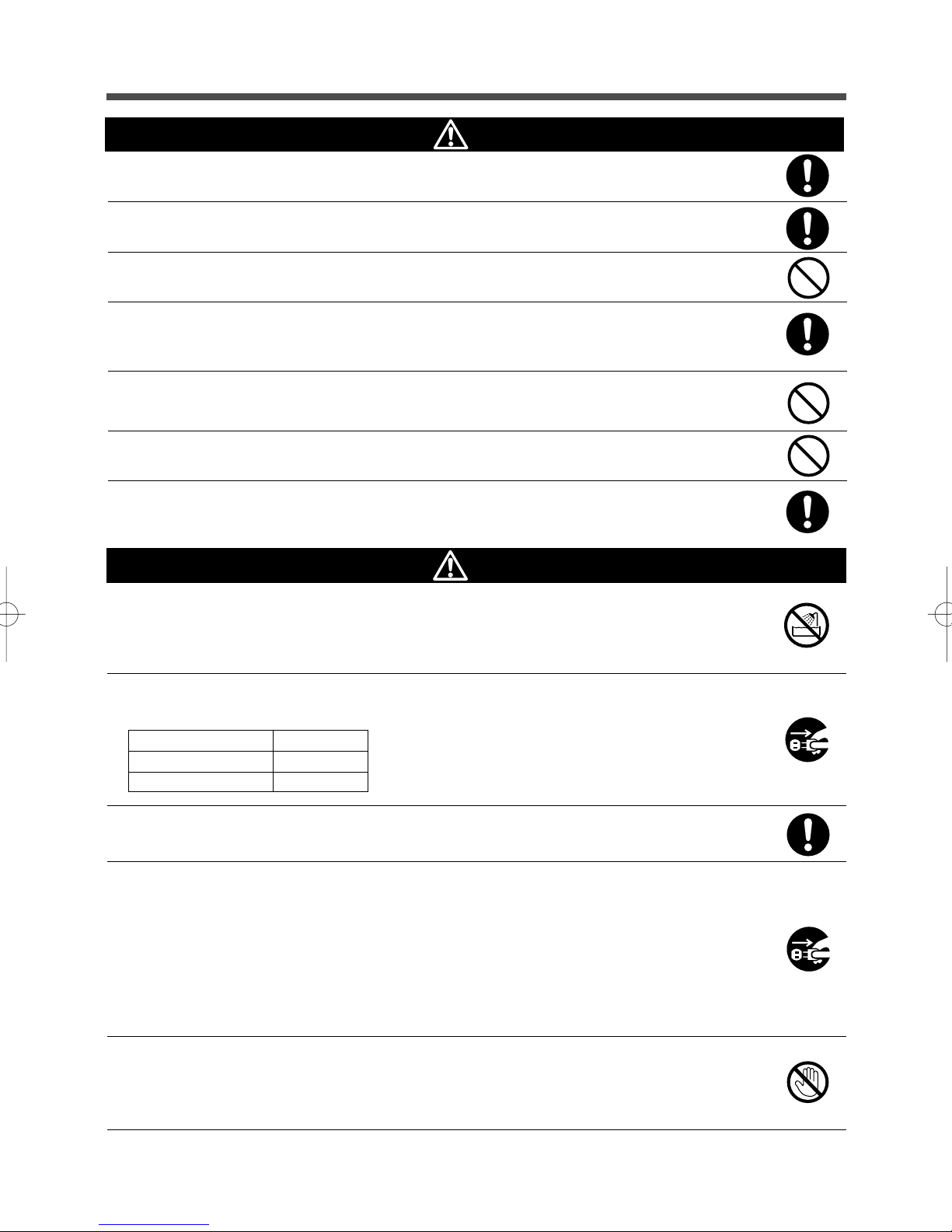
Ambient temperature
20°C
30°C
Wipe the 100-VAC input plug clean of dirt with a dry cloth occasionally.
● Settled dust may cause a fire.
If you notice abnormal sound or smell, smoke, or leakage from the inside,
immediately turn off the power switch and disconnect the 100-VAC input
plug from a wall outlet (commercial power).
● Using the unit under such conditions may cause a fire.
● If you notice such a condition, never use the unit and contact us; ____ for inspection and
repair.
● Use the unit under the conditions in which you can immediately disconnect the 100-VAC input
plug from a wall outlet (commercial power) in the case of an abnormal event.
Expected life
4 to 5 years
2 to 2.5 years
* The values in the table are the expected life under standard
use conditions and are not guaranteed.
If fluid leaks from the unit, do not touch the fluid.
● Doing so may cause blindness or burns.
● If the fluid contacts your eyes or skin, wash it out with lots of clean water and consult your
doctor.
5
Page 8
Safety precautions
Caution (for maintenance and discarding)
When maintaining connected equipment, turn off the power switch.
● Even if you disconnect the AC input plug while the UPS is operating, the power output of the
BX75XS2 is not stopped and 100 VAC is supplied from the wall outlet.
● Do not use liquid or spray detergent.
Do not disassemble, repair, or modify the unit.
● Doing so may cause an electric shock or a fire.
If fluid leaks from the unit, do not touch the fluid.
● Doing so may cause blindness or burns.
●
If the fluid contacts your eyes or skin, wash it out with lots of clean water and consult your doctor.
Do not throw the unit into fire.
● The lead battery in the unit may explode, or leak dilute sulfuric acid.
Caution (for battery replacement)
Perform replacement on a stable and flat place.
● Handle the battery carefully not to drop it.
● Not doing so could cause injury or burns due to liquid (acid) leakage.
Use a specified battery for replacement.
● Not doing so may cause a fire.
● Product model: BP75XSX (battery pack for BX75XS2)
Do not replace the battery in a place where there is flammable gas.
● Spark may occur when connecting the battery, which may cause an explosion or fire.
If fluid (dilute sulfuric acid) leaks from the battery, do not touch the fluid.
● Doing so may cause blindness or burns.
● If it contacts your eyes or skin, wash it out with lots of clean water and consult your doctor.
Do not disassemble or modify the battery.
● Doing so could cause dilute sulfuric acid leak, which could cause blindness and burns.
Do not drop the battery or do not give strong impact on it.
● Dilute sulfuric acid may leak.
Do not short the battery with metal objects.
● Doing so could cause an electric shock, fire or burn.
● Some electrical energy still remains inside the spent battery.
Do not put the battery into fire or do not break it.
● The battery may explode or leak dilute sulfuric acid.
● A battery can present a risk of electrical shock and high short circuit current.The following
precautions should be observed when working on batteries:
1) Remove watches, rings, or other metal objects from the hands.
2) Use tools with insulated handles.
3) Wear rubber gloves and boots.
4) Do not lay tools or metal parts on top of batteries.
5) Disconnect charging source prior to connecting or disconnecting batteries terminals.
6
Page 9

Safety precautions
Caution (for battery replacement)
● Servicing of batteries should be performed or supervised by personnel knowledgeable of
batteries and the required precautions. Keep unauthorized personnel away from batteries.
Notes
When moving the unit from a cold place to a warm place, leave it for several hours
before using it.
● If the unit is moved to a warmer place and the power is turned on soon, the unit failure may occur due to
condensation to the unit.
Charge the battery for at least 12 hours soon after purchasing the unit.
● If you do not use the unit for a long time after the purchase, the property of the battery may deteriorate and
the battery may become unusable.
● To charge a battery, connect the 100-VAC input plug of the unit to a wall outlet (commercial power).
When storing the unit, charge the battery for at least 12 hours and turn off the power
switch.
● Even if the unit is not used, the battery gradually discharges, and if it is left for a long time, it goes into an
over discharge state.
The backup time may become shorter or the battery may become unusable.
● The storable period of the built-in battery of the unit is 6 months after complete charging.
● If you want to store the battery longer than 6 months, connect the AC input plug of the unit to a commercial
power wall outlet for at least 12 hours within 6 months.
● Turn off the power switch of the unit during storage.
Do not short the output lines of the unit each other and the output lines to the ground.
● The unit may fail.
Do not connect the 100 VAC input plug of the unit to its Power Supply Output
Receptacle during the Battery Mode.
● The unit may fail.
Do not connect a page printer (laser printer, etc.) to the unit.
● The Commercial Power Mode and Battery Mode are repeated frequently, which may shorten the life of the
battery.
● As the peak current of a page printer is large, an excess of the connection capacity or a power failure due
to instantaneous voltage drop may be detected.
Do not use the unit for devices that malfunction due to an instantaneous power
failure of 10msec (0.01 second) or less.
● The connected device may stop due to switching time of 10msec or less.
Do not use the unit for inductive devices such as fluorescent lamps.
● Connected devices may stop due to a rectangular wave output.
● Inductive devices include devices incorporating transformers, coils, motors, and so on for their input.
7
Page 10

Safety precautions
Notes
Do not install or store the unit in a place exposed to direct sunlight.
● The rise of temperature may cause the built-in battery to deteriorate rapidly and become unusable.
Do not perform a withstand voltage test.
● The input circuit has a built-in surge absorption device. A withstand voltage test may break it.
● When performing an insulation resistance test, use the 250VDC range.
Before turning off the commercial power, turn off the power switch of the unit.
If you cannot turn off the power switch, it is recommended to use UPS monitoring
software to automatically stop the unit with the minimum backup time.
● When you stop commercial power, the Battery Mode starts. If you frequently use the unit in the Battery Mode
after turning off the commercial power, charging and discharging of the battery is repeated and the battery
life decreases extremely. The less the amount of charging and discharging is, the less the adverse effect on
the life becomes.
Notes
Recycling and Discarding the Battery
● The UPS uses a lead acid battery. It is recyclable, precious resources. Please recycle it
when you replace it or discard the produce you do not use any more.
Pb
Explanation
Usual operation
● You may either leave the power switch of the unit on (operation status) or turn it off each time when stopping
the connected system. You can choose either of the operation methods for your convenience. We recommend turning off the power switch when you do not use connected devices for a long time.
● The battery is charged when the 100 VAC input plug of the unit is connected to a wall outlet (commercial
power).
End of Battery Mode
● If a power failure lasts long, the battery discharges and power output from the unit stops. Shut down your
computer after performing appropriate procedure (for example, saving data) while the unit supplies power.
Reboot
● If the battery discharges completely during a power failure, the unit stops. After the recovery from the power
failure, the unit automatically restarts and supplies power. If you do not want to restart connected devices,
turn off the power switch of either the unit or the connected devices.
8
Page 11
1. Preparation
1. Preparation
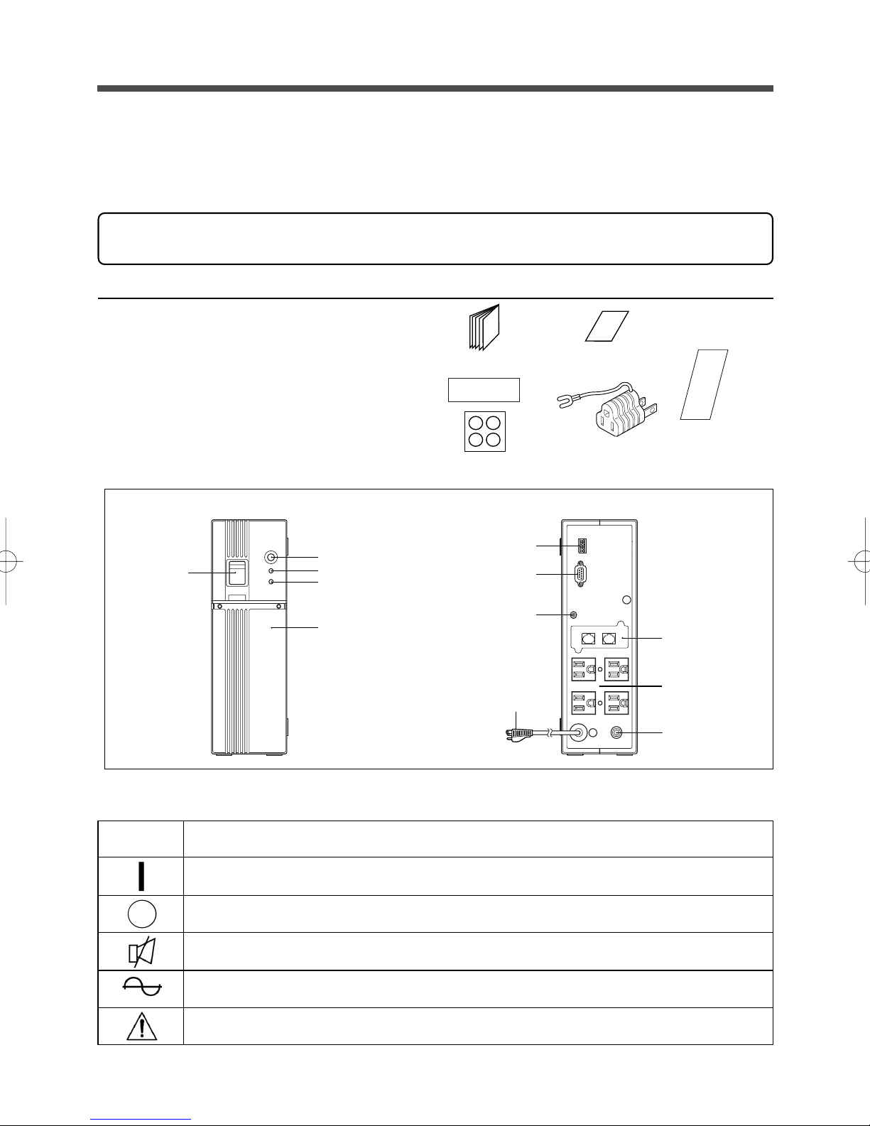
1-1 Checking the contents
Check whether all the package contents are included and there is no damage found on their appearance.
If you should notice defects or anything wrong, contact us; ____
BX75XS2
1. Instruction Manual ................................... 1 pc.
2. Warranty card .......................................... 1 pc.
3. User registration card .............................. 1 pc.
4. 3P-2P conversion adapter ....................... 1 pc.
5. Rubber feet .............................................. 4 pc.
6. Label (Judgment of Operation Mode) ..... 1 pc.
Instruction Manual
Warranty card
User registration card
85
200
Lavel
1-2 Name of each part
Front view
Beep Stop/Test Switch
Power Switch
Alarm Lamp (red)
Power Output (green)
Battery Replacement
Cover
Rubber feet
Setting Switch
Contact Signal
Connector
Grounding
Te rminal
100VAC Input
Cord and Plug
3P-2P conversion plug
Rear view
1-3 Explanetion of symbol used on unit
Symbol Description
Network Surge
Protection
(Option)
Power Supply
Output Receptacle
AC Input Overcurrent
Protection
Start the UPS.
Stop the UPS.
Suspend a beep.
UPS output power enable, supplied by operating on line mode, battery mode.
UPS has Error.
9
Page 12
2. Installation and connection
2. Installation and connection
2-1
Precautions and notes on installation and connection
Caution
(for installation and connection)
Carry the unit considering its weight and balance and place it on a stable
and robust base.
● Dropping or toppling the unit may cause injury.
● The weight of the unit is approximately 7.7 kg.
● If you drop the unit, stop using it and the unit must be inspected and/or repaired.
For repair, contact us; ____
Keep plastic package bags out of reach of children.
● They may put their head into it, and may be suffocated.
Be sure to connect the input plug of the unit to a wall outlet (commercial
power) of 100VAC (50/60Hz).
● Connecting it to a wall outlet (commercial power) of a different voltage may cause a fire.
● The unit may fail.
Connect the unit to a wall outlet (commercial power) with a current capacity
larger than 12A.
● Otherwise, the power cord may be heated.
● When the equipment of the maximum output capacity is connected, the current flows up to
12A.
Provide secure grounding.
● For a 3P wall outlet, directly connect the 100 VAC input plug of the unit to it.
(Refer to "2. Installation and connection" on page 13.)
Not doing so may cause an electric shock in case of a operation failure or any leakage.
● When you use the 3P-2P Conversion Plug for the 100 VAC input plug, be sure to perform
grounding before connecting the 100 VAC Input Plug into a wall outlet (commercial power).
Do not disconnect the grounding before disconnecting the 100 VAC input plug from a wall
outlet (commercial power).
● Grounding is necessary to enable its surge protection function. For repair, contact us; ____
Do not disassemble, repair, or modify the unit.
● Doing so may cause an electric shock or a fire.
Do not install the unit in other than specified orientations.
● Dropping or toppling the unit may cause injury.
● If you install the unit in an orientation other than specified, the unit cannot be protected from a
battery fluid leakage.
When installing the unit vertically, do not put any object on it.
When installing the unit horizontally, do not put any object heavier than
25kg.
● Doing so may cause distortion of/damage to the case, which may cause a fire.
10
Page 13
2. Installation and connection
Caution
(for installation and connection)
Do not use the unit where the maximum temperature exceeds 40°C.
● The battery becomes week rapidly, which may cause a fire.
● Doing so may cause a failure or malfunction of the unit. Do not install or store the product in
the places listed below.
Do not install or store the unit in a place as listed below.
● The humidity is lower than 10%. The humidity is higher than 85%. A closed place such as in a
cabinet without clearance. There is flammable gas or corrosive gas. A place subject to vibration or shock. Outdoors.
● Installation or storing the unit in such a place may cause a fire.
Do not use the unit in a closed place or do not cover the unit.
● Doing so may cause abnormal heating or a fire.
Do not connect equipment that exceeds the output capacity of the unit.
● The current protection of the unit may operate, which may stop the output.
● The wiring of the plug strip heats up, which may cause a fire.
Do not pinch or tie the cable of the unit.
● Doing so may cause the cable to be damaged or heated, which may cause an electric shock
or a fire.
● If the cable is damaged, stop using the unit and the cable must be repaired.
For repair, contact us; ____
Notes
When moving the unit from a cold place to a warm place, leave it for several hours
before using it.
● If the unit is moved to a warmer place and the power is turned on soon, the unit failure may occur due to
condensation to the unit.
Charge the battery for at least 12 hours soon after purchasing the unit.
● If you do not use the unit for a long time after the purchase, the property of the battery may deteriorate and
the battery may become unusable.
● To charge a battery, connect the 100 VAC input plug of the unit to a wall outlet (commercial power).
When storing the unit, charge the battery for at least 12 hours before storage.
● Even if the unit is not used, the battery gradually discharges, and the battery is left for a log time, it goes into
an over discharge state.
The backup time may become shorter or the battery may become unusable.
● The storable period of the built-in battery of the unit is 6 months after complete charging.
● If you want to store the battery longer than 6 months, connect the AC input plug of the unit to a commercial
power wall outlet for at least 12 hours within 6 months.
● Turn off the power switch of the unit during storage.
Do not short the output lines of the unit each other and the output lines to the ground.
● The unit may fail.
11
Page 14

2. Installation and connection
Notes
Do not connect the 100 VAC input plug of the unit to its Power Supply Output
Receptacle during the Battery Mode.
● the unit may fail.
Do not connect a page printer (laser printer etc.) to the unit.
● The Commercial Power Mode and Battery Mode are repeated frequently, which may shorten the life of the
battery.
● As the peak current of a page printer is large, an excess of the connection capacity or a power failure due
to instantaneous voltage drop may be detected.
Do not use the unit for devices that malfunction due to an instantaneous power
failure of 10msec (0.01 second) or less.
● The connected device may stop due to the switching time of 10msec or less.
Do not use the unit for inductive devices such as fluorescent lamps.
● Connected devices may stop due to a rectangular wave output.
● Inductive devices include devices incorporating transformers, coils, motors, and so on for their input.
Do not install or store the unit in a place exposed to direct sunlight.
● The rise of temperature may cause the built-in battery to deteriorate rapidly and become unusable.
Do not perform a withstand voltage test.
● The input circuit has a built-in surge absorption device. A withstand voltage test may break it.
● When performing an insulation resistance test, use the 250 VDC range.
12
Page 15

2. Installation and connection
2-2 Installation and connection
Connection to back up your computer and peripherals
(1) Disconnect all AC input plugs of your computer and peripherals from a wall outlet (commercial power).
Wall outlet
(commercial power)
Computer
Modem or other
(2) Install the unit.
Write the date of starting use on the label on the side.
peripheral
● Do not use this unit in an orientation other than the correct ones shown in the figure below.
Vertical Correct installation orientation
Horizontal
* Stick the attached rubber feet in the 4 corners on the bottom surface.
Wrong installation orientation
✕✕
Placing the front
downward.
Placing the rear
downward.
13
✕
Placing the left side
downward.
Page 16

2. Installation and connection
(3) Connect devices you want to back up to the Power Supply Output Receptacles of the unit.
You can connect devices of up to 750 VA (7.5A) or 450W in total.
Computer
Modem or other peripheral
A Grounding Terminal is provided for such cases
as the AC plug does not provide any grounding
means.
• Even if the input plug of a device you want to connect is 2-pin type, you can connect it
directly to the Power Supply Output Receptacle of the UPS. Note that if the input plug is
2-pin type with a grounding wire, connect the grounding wire to the Grounding Terminal
of the UPS.
•IF you want to use an AC adaptor, connect it to a Power Supply Output Receptacle of
the UPS with sufficient space for the connection.
(4) When the installation and connection are complete, connect the 100 VAC input plug of this unit to a wall
outlet (commercial power).
When you connect the 100 VAC input plug of this unit to a wall outlet (commercial power), battery charging
automatically starts regardless of the on/off state of the Power Switch and charging completes within 12
hours.
< 3P wall outlet > < 2P wall outlet >
Wall outlet
(commercial power)
Connect it directly.
100 VAC input
plug of the unit
● Precautions for grounding connection
Connect the
grounding wire to the
grounding terminal
equipped to the
building. (Grounding
means must be
provided if there is
none.)
Wall outlet
(commercial power)
Use the attached 3P-2P
Conversion Plug.
Attached 3P-2P
Conversion Plug
Plug of connected
device
The backup function of the unit will not be affected even if you do not ground it, but please note the
following:
• Attenuation effect against surge voltage caused by lightning, etc. decreases.
• If connected devices are not grounded, you may get an electric shock due to leak current when you
touch metal parts.
14
Page 17

2. Installation and connection
2-3 Checking the operation
When you are complete with connecting devices to the unit, the backup function must be confirmed.
Check that the Battery Mode is performed normally according to the following procedure.
This operation check simulates a power failure by disconnecting the AC input plug from a wall outlet.)
(1) Turn on the Power Switch of this unit.
The beeper sounds and the Power Output Lamp goes on.
After 5 secounds, the self-diagnostic test is performed in Battery Mode for approximately 3 seconds.
When the self-diagnostic test finishes successfully, switching to 100 VAC output from commercial power is
performed and the following display is obtained.
(If the battery voltage is low, the self-diagnostic test is not performed and the operation starts immediately,
using output from commercial power.)
(Red) Alarm Off
(Green) Power Output On
(2) Bring all the connected devices into operation.
(Including devices connected to the AC outlet of your PC.)
Operate the devices in a way in which abrupt power stop does not damage the connected devices, data,
etc.
This unit has been charged prior to shipment. However, the backup time becomes shorter when using it for
the first time due to spontaneous discharge. We recommend charging this unit before using it.
(3) Under this condition, check the display lamps and a beep of this unit.
Are they in the same status as shown below?
(Red) Alarm Off
(Green) Power Output On
Beep None
Power Supply Output Receptacles Supply power (connected devices are powered).
Are the same as shown above. ➜ The operation is normal. Proceed to (4).
Are not the same as shown above. ➜ The operation is abnormal. One of the description in "3. Display
and beep when a failure occurs in equipment" of "4-3 Interpreting a
beep and display" on page 21 must apply.
Take necessary measures and then proceed to (4).
(4) Disconnect the 100-VAC input plug of this unit from a wall outlet (commercial power).
The UPS enters Battery Mode.
(5) In Battery Mode, check the display lamps and a beep of the unit.
Are the lamps in the same status as A or B below?
AB
(Red) Alarm
(Green) Power Output
Beep (when the beep setting is ON)
Beep (when the beep setting is OFF)
Power Supply Output Receptacles
Off
Blinks with an interval of 4 seconds
Beeps with an interval of 4 seconds
None
Supply power.
(Connected devices are powered.)
Off
Blinks with an interval of 1 second
Beeps with an interval of 1 second
None
Supply power.
(Connected devices are powered.)
15
Page 18

2. Installation and connection
Are the same as shown above. ➜ When A: Operation is normal. The battery is charged sufficiently.
➜ When B: Operation is normal, but the battery is not sufficiently
charged.
Are not the same as shown above. ➜ Operation is abnormal. Check the status of lamps and beep and
turn off the Power Switch.
• If the display is No.7 or No.8 of "3. Display and beep when a
failure occurs in equipment" of "4-3 Interpreting a beep and display" on page 21, take necessary measures and then go back
to (1) on page 15.
• If no Battery Mode is performed and the UPS and the connected
devices stop, insufficient charging of the battery is suspected.
Connect the 100 VAC input plug of the UPS to a wall outlet (commercial power), charge the battery for approximately 6 hours,
and then go back to (4) on page 15.
• If the problem persists after checking the 2 points above, contact us; ____
(6) Connect the 100 VAC input plug to a wall outlet (commercial power) again.
The Power Output Lamp stops blinking and turns on without intervals, and the beeper stops.
(The status is as shown below.)
(Red) Alarm Off
(Green) Power Output On
Beep None
Power Supply Output Receptacles Supply power (connected devices are powered).
Checking the operation is now complete.
Installation and connection is now complete.
16
Page 19

3. Preparation for operation
3. Preparation for operation
3-1 Charging the battery
When you connect the 100 VAC input plug of this unit to a wall outlet (commercial power), the battery
charging automatically starts regardless of the on/off state of the Power Switch, and it is fully charged
within 12 hours.
● This unit has been charged prior to shipment. However, the backup time becomes shorter when using it for
the first time due to spontaneous discharge. We recommend charging this unit before using it.
● When you do not perform "3-2 Measuring the initial value of backup time" described next, proceed to "4.
Operation."Page 18
3-2 Measuring the initial value of backup time
● Before starting operation for the first time, measure the backup time initial value of the unit in your environment. You can use it as a guide to check the battery.
See also
"7. Measuring the backup time" → Page 33
3-3 Recharging the battery
The battery is discharged completely when the backup time is measured, so you need to recharge it before
using the UPS.
● You can use connected devices while recharging the battery, but the backup time when a power failure
occurs is shorter until the battery is fully charged.
(If a power failure occurs immediately after the start of charging, backup stops immediately.)
See also
Preparation for starting operation is now complete.
Charge the battery as described in "3-1 Charging the battery."
17
Page 20

4. Operation
4. Operation
4-1 Precautions and notes on operation
Caution (while in use)
Do not wet or dash water onto the unit.
● Doing so may cause an electric shock or a fire.
● If you wet the unit, stop using it and the unit must be inspected and/or repaired.
For repair, contact us; ____
If the battery is dead, replace it immediately or stop using the unit.
● Continued use of the unit may cause a fire.
● For information on how to check the battery, refer to "5. Maintenance and inspection" on page 25.
● For information on how to replace the battery, refer to "5-2 Replacing the battery" on page 26.
Ambient temperature
20°C
30°C
Expected life
4 to 5 years
2 to 2.5 years
* The values in the table are the expected life under the standard
use conditions and are not the guaranteed values.
Wipe the 100 VAC input plug clean of dirt with a dry cloth occasionally.
● Leaving dirt for a long time may cause a fire.
If you notice abnormal sound or smell, smoke, or leakage from the inside,
immediately turn off the Power Switch of this unit and disconnect the
100-VAC input plug from a wall outlet (commercial power).
● Continued use of this unit under such conditions may cause a fire.
● If you notice such a condition, never use the unit and contact us; ____ for inspection and
repair.
● Use the unit under the conditions in which you can immediately disconnect the 100 VAC input
plug from a wall outlet (commercial power) in the event of the occurrence of an abnormal
condition.
If liquid leaks from this unit, do not touch the fluid.
● Doing so may cause blindness and/or burns.
● If it contacts your eyes or skin, wash it out with lots of clean water and consult your doctor.
Notes
Before turning off the commercial power, turn off the Power Switch of this unit.
If you cannot turn off the Power Switch, it is recommended to use the UPS
monitoring software to automatically stop the unit in the minimum backup time.
● If you stop commercial power with the Power Switch in the ON position, the Battery Mode starts. If you
frequently use the unit in the Battery Mode after turning off the commercial power, charging and discharging of the battery is repeated and the battery life decreases extremely. The less the amount of charging
and discharging is, the less the adverse effect on the life becomes.
18
Page 21

4. Operation
Explanation
Usual operation
● You may either leave the power switch of the unit on (operation status) or turn it off when shutting down the
connected system. You can choose either of the operation methods for your convenience.
● Connecting the UPS to a wall outlet (commercial power) charges the battery.
End of Battery Mode
● If a power failure lasts long, the battery discharges and power output from the unit stops. Shut down your
computer after performing appropriate procedure (for example, saving data) while the unit still supplies
power.
Reboot
● If the battery discharges completely during a power failure, the unit stops. After the recovery from the power
failure, the unit automatically restarts and resumes power supply. If you do not want to restart connected
devices, turn off the power switch of either the unit or the connected devices.
4-2 Start and stop procedures and basic operation
● When the 100 VAC input plug is connected to a wall outlet and the power switch is
in the OFF position:
•All the lamps are turned off.
• Power output is stopped.
• The battery is charged automatically.
● Start procedure
Operation
Turn on the power switch of the UPS.
• The beeper sounds and the Power Output Lamp goes on.
•After 5 seconds, the self-diagnostic test is performed in Battery Mode for approximately 3 seconds.
(If the battery voltage is low, the self-diagnostic test is not performed. It is automatically executed after
the battery is charged.)
• When the self-diagnostic test finishes successfully, switching to 100 VAC output from commercial power
is performed and normal operation starts.
• If the self-diagnostic test is not executed, the UPS immediately starts outputting 100 VAC from commercial power.
(Red) Alarm Off
(Green) Power Output On
Beep None
Power Supply Output Receptacles Supply power (connected devices are powered).
• During operation, the battery is charged automatically.
19
Page 22

4. Operation
● Operation during a power failure
• If a power failure or abnormal input power supply occurs, the UPS automatically switches to Battery
Mode, continuing power output from the Power Supply Output Receptacles supplied from the battery.
• The Power Output Lamp blinks and the beeper sound continuously to alert the user.
See also
(Red) Alarm
(Green) Power Output
Beep (when the beep setting is ON)
Beep (when the beep setting is OFF)
Power Supply Output Receptacles
The setting switch 3 lets you select ON/OFF of the beeper. Page 24
AB
Off
Blinks at intervals of 4 seconds
Beeps at intervals of 4 seconds
None
Supply power.
(Connected devices are powered.)
Off
Blinks at intervals of 1 second
Beeps at intervals of 1 second
None
Supply power.
(Connected devices are powered.)
•If the battery is sufficiently charged, the lamps and beep in the status shown in "A" will be observed.
• If the battery becomes weak, the lamps and beep shown in "B" are obtained.
• If the battery is discharged completely, power output from the Power Supply Output Receptacles stops
and the lamp display and beeper also stop.
● Operation during recovery from a power failure
• If a power failure or abnormal power input is resolved while the UPS supplies power, it returns to the
commercial power output status automatically. Charging the consumed battery starts.
• If a power failure or abnormal power input is resolved after the battery is discharged completely and
power output is stopped, the UPS restarts automatically and resumes power output. Charging the
consumed battery starts.
● Stop procedure
Operation
• The Power Output Lamp goes out and power output from the UPS stops.
• Even if you turn off the power switch, if 100 VAC is supplied from commercial power, the battery is
Turn on the power switch of the UPS.
(Red) Alarm Off
(Green) Power Output Off
Beep None
Power Supply Output Receptacles Power output is stopped (connected devices
are stopped).
automatically charged.
20
Page 23

4-3 Interpreting a beep and display
4. Operation
On Off Blink
●
1. Display and beep during normal operation
No.
Display lamp
1
Alarm
●
Power Supply Output
●
Alarm
2
●
Power Supply Output
●
Alarm
3
●
Power Supply Output
Beep
None
None
None
Output
Stop
Stop
ON
Charging
Stop
ON
ON
100 VAC input not supplied.
Operation stopped.
100 VAC input supplied.
Power Switch: OFF.
Power Switch: ON
100 VAC input is normal. In normal operation.
Description
2. Display while testing
No.
Display lamp
4
Alarm
●
Power Supply Output
4-second interval
Beep
None
Output
ON
Charging
Stop
Discharging
Description
Self-diagnostic test or battery test in process
3. Display and beep during power failure or abnormal voltage input
No.
Display lamp
5
Alarm
●
Power Supply Output
4-second interval
Alarm
6
●
Power Supply Output
1-second interval
Beep
Intermittent
4-second interval
(When setting is ON)
Intermittent
1-second interval
(When setting is ON)
Output
ON
ON
Charging
Stop
Discharging
Stop
Discharging
Description
Operating in Battery Mode because of
power failure or the input voltage over
110V or less than 90V. If operation in
Battery Mode is continued, the battery
runs down.
(Same as above)
Because the battery is weak, output will
stop soon.
Remedy
____________
____________
____________
Remedy
____________
Remedy
Shut down the connected devices after
performing shutdown procedure.
(Same as above)
4. Display and beep when a failure occurs in equipment
ON
ON
Charging
ON
Stop
750VA is exceeded due to too many connected devices. Backup will not be performed against power failure in this status. If this status continues longer than 5
minutes, it results in the status described
in No.8 occurs and output will be
stopped.
Stopped because of a unit failure or the
connection capacity exceeded.
If the excess of the connection capacity
is 120% or more, the unit immediately
enters the status No.8 instead of No.
No.
Display lamp
7
Alarm
0.5-second interval
Power Supply Output
Alarm
8
Power Supply Output
●
Output
Beep
Intermittent
0.5-second interval
Short beep
Continuous
5. Display and beep when battery replace occurs
No.
Display lamp
9
Alarm
2-second interval
Power Supply Output
Beep
Intermittent
2-second interval
Short beep
Output
ON
Charging
ON
It has been detected that the battery is
weak by the battery test.
21
Description
Description
Remedy
Decrease the number of connected
devices until the display disappears
and the unit returns to the status No.3.
Tu rn off the UPS and all the connected
devices, and turn on only the Power
Switch of the UPS again. If the Alarm
Lamp goes on again, the UPS is at fault.
Contact us; ____ If the unit goes into the
status No.3, reduce the number of
connected devices.
Remedy
Replace the battery. You can replace it
with an optional spare battery by
yourself. Refer to "5. Maintenance and
inspection" on page 25.
Page 24

4. Operation
4-4 Suspending a beep
You can suspend a beep by pressing and holding the Beep Stop/Test Switch while a beep is sounding for 0.5
second or longer.
You can suspend a beep in the following statuses.
● During Battery Mode
When the Battery Mode is resumed and the battery goes weak, a beep sounds again.
In this case also, you can suspend a beep.
● When a failure occurs in equipment (the Alarm Lamp is on)
● When battery replacement is required (the Alarm Lamp blinks at intervals of 2 seconds)
You cannot suspend a beep when connection capacity is exceeded.
Take necessary countermeasures according to the remedy of No.7 in "4. Display and beep when a failure
occurs in equipment" on page 21.
4-5 Description of the self-diagnostic test function
You can use the following procedure to check whether a failure occurs inside the UPS and whether replacing
the battery is required.
If the battery is not fully charged, the self-diagnostic test is not executed immediately.
After charging is complete, it is automatically executed.
(1) Connect your computer and other devices to the UPS and then turn on the power switch of the UPS.
(2) Press and hold the Beep Stop/Test Switch of the UPS for 0.5 second or longer.
Release the Beep Stop/Test Switch when a beep sounds. The Battery Mode starts for testing purpose. (No
beep sounds.) When the test is complete, the normal operation automatically starts.
(3) If the Alarm Lamp blinks and the beeper sounds:
See also
Take necessary countermeasures according to the remedy in "4. Display and beep when a failure occurs
in equipment." or "5.Display and beep when battery replace."
"4-3 Interpreting a beep and display" ➛ Page 21
22
Page 25

4. Operation
4-6 Description of the auto battery test function
This UPS provides functions to automatically check whether replacing the battery is required and whether the
internal circuit is at fault. (You do not have to perform any operation.)
The test is performed at intervals of 4 weeks after the AC Input Plug is connected to a wall outlet (commercial
power). If you disconnect the AC Input Plug from a wall outlet (commercial power) when the Power Switch of
the UPS is OFF, the 4-week timer is reset. If the Power Switch is OFF, the test is not performed.
(1) When the auto battery test starts, the Battery Mode automatically starts. (No beep sounds.) After the auto
battery test is complete, the normal operation automatically starts.
(2) If the Alarm Lamp blinks and the beeper sounds:
See also
Take necessary countermeasures according to the remedy in "4. Display and beep when a failure occurs
in equipment." or "5.Display and beep when battery replace."
The setting switch on the rear of the UPS allows you to select the "disable the auto battery test" setting.
See also
"4-3 Interpreting a beep and display" ➛ Page 21
"4-7 Changing the setting of the functions" ➛ Page 23
See "●Auto battery test ON/OFF setting."
4-7 Changing the setting of the functions
1. Selecting functions with the setting switches
Operation
● Power output stop delay time setting (setting switches 1 and 2 ) … Factory-
After changing the setting switches, turn on the Power Switch again.
•Otherwise, the change will not take effect.
shipped setting: ON and ON
When the UPS Stop Signal is received, the UPS stops after a specified time period has elapsed.
(1)When you perform shutdown processing for Windows ME using "PowerCredit" the UPS monitoring
software you can purchase separately, set the delay time.
See also
(2) When you perform shutdown processing using the UPS management software of Windows NT or using
"PowerCredit" the UPS monitoring software for Windows 98/95, set the switches to ON and OFF (no
delay time).
See also
See also
When performing the auto shutdown processing by the UPS monitoring software ➛ Page 37
When performing the auto shutdown processing by WindowsNT's UPS management software
➛ Page 39
When performing the auto shutdown processing by the UPS monitoring software
➛ Page 37
23
Page 26

4. Operation
(3) When you perform auto shutdown processing using the UPS management software of Windows XP/2000,
set the delay time.
See also
When performing the auto shutdown processing by Windows XP/2000's UPS management
software ➛ Page 38
Setting switch 1 Setting switch 2 Power output stop delay time
OFF OFF Does not stop power output.
ON
1 2 3 4
5
ON OFF 0 second
OFF ON 60 seconds
ON ON 120 seconds
● Beeper ON/OFF setting (setting switch 3 ) … Factory-shipped setting: ON
ON
1 2
53 4
ON: The beeper sounds when an alarm is necessary.
OFF: The beeper does not sound when the Battery Mode starts. When the Alarm Lamp (red) goes on
or blinks (excess of connection capacity, battery replacement, abnormal operation, and so on),
the beeper sounds.
●
UPS Stop Signal setting (setting switch 4 ) … Factory-shipped setting: ON
ON
1 2
53 4
ON: You can stop power output from the UPS by inputting the UPS Stop Signal (HIGH) that lasts at
least 0.01 second (10 ms). The Stop Signal is accepted only in the Battery Mode to stop power
output.
After the output is stopped, when abnormal power such as a power failure is resolved, the UPS
automatically restarts.
If you do not want to stop the UPS in Commercial Power Mode even if the UPS Stop Signal is
inputted, use this setting.
OFF: You can stop power output from the UPS by inputting the UPS Stop Signal (HIGH) that lasts at
least 10 seconds. Voltage signal input stops power output even in Commercial Power Mode.
After the output is stopped, if commercial power is normal, the UPS automatically restarts.
Auto battery test ON/OFF setting (setting switch 5 ) … Factory-shipped setting: ON
●
ON
1 2 53 4
ON: The battery test is automatically executed at intervals of 4 weeks.
OFF: The auto battery test is disabled.
If you want to disable Battery Mode for the test performed regularly, use this setting.
24
Page 27

5. Maintenance and inspection
5. Maintenance and Inspection
Caution (maintenance and discarding)
When maintaining connected equipment, turn off the Power Switch of this
unit to stop it.
● Even if you disconnect the AC Input Plug while the UPS is operating, the power output of the
BX75XS2 is not stopped and 100 VAC is supplied from the outlet.
Do not disassemble, repair, or modify the unit.
● Doing so may cause an electric shock or a fire.
If liquid leaks from this unit, do not touch the fluid.
● Doing so may cause blindness or burns.
● If it touches your eyes or skin, wash it out with lots of clean water and consult your doctor.
Do not discard this unit into fire.
● The lead battery in this unit may explode or dilute sulfuric acid may leak.
5-1 Checking the battery
The sealed lead battery used in the UPS has its life.
(The life varies depending on your storage/use environment and backup frequency.)
The nearer the end of the life is, the more rapidly deterioration proceeds.
• Although you can judge the life by the auto battery test (page 23), if you want to judge it more accu-
rately, check the battery following the procedure below.
1. Life of battery (estimated replacement timing)
Ambient temperature
20°C
30°C
Life of battery
4 to 5 years
2 to 2.5 years
2. Method to check the battery
See also
If the measured value is equal to the "initial value of the backup time" or less than half the value obtained
from the graph of "Estimated backup time" on page 35, replace the battery.
•When you compare the "initial value of the backup time" you measured and the current backup time,
Measure the backup time according to "7-1 Measuring method of the backup time."
➛ Page 33
make the capacity of devices connected to the UPS same as when you measured the initial value to
make judgment accurately.
3. Guideline on the frequency of checking the batter (measuring the backup time)
Ambient temperature
20°C
30°C
Check at intervals of 6 months
Until 3 years from purchase
Until 1.5 years from purchase
Replacement estimation
4 years after staring use
2 years after staring use
Check at intervals of 1 month
From after 3 years
From after 1.5 years
* The battery deteriorates even if it is stored. The higher the temperature is, the shorter the
life becomes.
25
Page 28

5. Maintenance and inspection
5-2 Replacing the battery
You can change the battery of the UPS by yourself.
*When replacing the battery, stop the connected devices, turn off the Power Switch of the UPS, and
disconnect the 100 VAC Input Plug from the wall outlet.
If the display and beep for "battery replacement" are output, stop them when turning off the Power
Switch.
Caution (battery replacement)
Risk of electric shock.
● Battery circuit is not isolated from ac input, hazardous voltage may exist between battery
terminal and ground. Test before touching.
Perform replacement on a stable, flat place.
● Not doing so could cause injury due to falling or burns due to leak of liquid (acid).
● Hold the battery securely with your both hands not to drop it.
Do not use a replacement battery other than specified.
● Doing so may cause a fire.
● Product model: BP75XSX (battery pack for BP75XS2)
Do not replace the battery in a place where there is flammable gas.
● Sparking may occur when connecting the battery, which may cause an explosion or fire.
If liquid (dilute sulfuric acid) leaks from the battery, do not touch it.
● Doing so may cause blindness or burns.
● If it touches your eyes or skin, wash it out with lots of clean water and consult your doctor.
Do not disassemble or modify the battery.
● Doing so could cause leak of dilute sulfuric acid, which could cause blindness and burns.
Do not drop the battery or do not give strong impact on it.
● Dilute sulfuric acid may leak.
Do not short the battery with metal objects.
● Do not insert metal objects into the Battery Connection Connector. Doing so could cause an
electric shock, fire or burn.
● Doing so may cause burns or a fire.
● Some electrical energy remains inside the battery even if it is exhausted.
Do not put the battery into fire or do not break it.
● The battery may explode or dilute sulfuric acid may leak.
Notes
Recycling and Discarding the Battery
The UPS uses a lead acid battery. It is recyclable, precious resources. Please recycle it
when you replace it or discard the produce you do not use any more.
Pb
26
Page 29

5. Maintenance and inspection
Procedure to replace the battery
● Preparation
(1) Prepare the BP75XSX spare battery pack you can purchase separately.
(2) If you place the UPS horizontally and put a heavy object such as CRT on it, put it down until you finish
replacement.
● Replacing the battery
(3) Turn the 2 screws on the front panel of the UPS counterclockwise to remove them.
Pull the front panel towards you to remove it.
Turn the 2 screws to remove them. Remove the front panel.
(4) Pull out the Batter Connector while pushing its hook.
Slide the metal cover towards you to remove it.
Pull out the connector while pushing its hook. Slide the font metal cover to remove it.
(5) Hold the label stuck to the battery pack and remove it.
Insert the new battery pack.
Caution
● If liquid (dilute sulfuric acid) leaks from the battery do not touch the fluid.
Do not make the batter pack upside down.
• Doing so could cause burns and, if it is put into your eye, blindness.
• If the liquid touches your eyes or skin, wash it out with lots of clean water and consult your doctor.
• Just put the spare batter pack into the packaging plastic bag and seal it with tape.
● Do not drop the battery pack.
• If you see red tape stuck on the top of the battery pack, you can remove the battery completely by
pulling it 10 cm further.
Hold the battery securely not to drop it.
● Do not remove the battery by holding the cables.
Pull out holding the label. Insert the new battery pack.
27
Page 30

5. Maintenance and inspection
(6) Insert and slide the metal cover to secure it.
Connect the Battery Connector. After connection, pull the connector lightly to make sure it is not disconnected.
When you connect the battery pack to the UPS, you may hear a short sound but it is not
abnormal.
Fit and slide the metal cover to
secure it.
Connect the Battery Connector.
After connection, pull the connector
lightly to make sure it is not disconnected.
(7) Fit the front panel.
Turn the 2 screws to secure the font panel clockwise with a screwdriver.
Fit the front panel. Tighten the 2 screws.
< Procedure after replacement of the battery >
Connect the 100-VAC Input Plug to a wall outlet (commercial power) and turn on the Power Switch of
the UPS. When operation starts, the self-diagnostic test is executed automatically. After approximately
3 seconds, when the test is complete, the normal operation resumes.
Battery replacement is now completed.
Write the date of replacement on the label on the side of the UPS.
28
Page 31

5. Maintenance and inspection
5-3 Cleaning
● Cleaning the UPS
Wipe the UPS lightly by tight squeezed soft cloth soaked with water or detergent
Do not use chemicals such as thinner and benzene. (They cause deformation or discoloration.)
● Removing dust from the Power Plug
•Turn off connected devices and the Power Switch of the UPS.
•Disconnect the 100 VAC Input Plug from a wall outlet (commercial power) and remove dust around the
plug with a dry cloth.
•Disconnect the AC plugs of the connected devices from the UPS and clean them also.
• Connect the AC plugs of the connected devices to the UPS again, and connect the 100 VAC Input Plug
of the UPS to a wall outlet (commercial power).
(For information on the connection procedure:)
See also
"2. Installation and connection" ➛ Page 10
29
Page 32

6. Using the Contact Signal
6. Using the Contact Signal
You can develop your unique system based on the following specifications to automate the process at the
power failure.
Your can perform power-failure or closing procedure of the system by detecting the Backup Signal and the
Battery Low Signal, or receive failure notification by detecting the Trouble Signal.
You can stop the UPS by inputting the UPS Stop Signal from the system, and remote control start and stop of
the UPS by using the Remote ON/OFF Signal.
1. Signal output
The UPS has 4 kinds of output signals. The output circuit consists of an open collector circuit using a photo
coupler (a kind of electronic switch).
● Backup Signal output: BU
Backup Signal reverse output: BU
BU stays ON (BU OFF) during a power failure.
● Battery Low Signal output: BL
Goes ON when the battery becomes weak during the
Battery Mode.
● Trouble Signal output: TR
Goes ON when an internal failure of the UPS occurs.
BU-COM ON when a power failure occurs
BU-COM OFF when a power failure occurs
BL-COM ON when the battery is low
TR-COM ON when a power failure occurs
2. Input of the UPS Stop Signal (BS)
Stops the output of the BX75XS2 after the time period specified by the "power output stop delay time
setting" (setting switches 1 and 2 ) has elapsed.
When the "UPS Stop Signal setting" (setting switch 4 ) is set to OFF:
(1)
You can stop the output of the BX75XS2 by inputting the voltage signal (HIGH) that lasts at least 10
seconds from the outside.
(2)
When the "UPS Stop Signal setting" (setting switch 4 ) is set to ON:
You can stop power output by inputting the voltage signal (HIGH) that lasts at least 0.01 second (10
ms) from the outside that is accepted only during backup.
See also
"4-7 Changing the setting of the functions" ➛ Pages 23 and 24
BS-COM ON when a failure occurs
3. Remote ON/OFF Signal
You can start and stop the UPS depending on the contact connected
to the outside and the ON/OFF status of the open collector circuit.
To use this function, turn on the Power Switch of the UPS.
4. Connection to the system
Please make a cable to connect to the system by yourself.
See also
"8. Example of the use of the Contact Signal circuit" ➛ Page 33
External contact Operate
Open Start
Close Stop
30
Page 33

6. Using the Contact Signal
5. Contact Signal Connector (female DSUB9P)
Pin assignment Pin number Signal name
1TR
2BU
5 4 3 2 1
9 8 7 6
Front view
Screw size: inch screw
#4-40 UNC
3
4 COM
5BL
6BS
7 COM
8 Remote ON/OFF (+)
BU
9Remote ON/OFF (--)
6. Contact Signal ratings
● Signal output (BU, BU, BL, and TR) ● BPS Stop Signal input (BS)
Photo coupler ratings Input voltage HIGH 5 to 15 VDC
Appliable voltage: 35 VDC or less LOW 0.7 VDC or less
Maximum current: 10 mA
● Remote ON/OFF
Voltage between terminals: 5 VDC
Current when closed: 10 mA
7. Contact Signal circuit inside the UPS
BU
BU
BL
TR
3.3V 1kW
BS
COM
5V
Remote ON (+)
Remote OFF (-)
31
Page 34

6. Using the Contact Signal
8. Example of the use of the Contact Signal circuit
● Example of the use of the BU signal
BU
COM
UPS side
Connecting cable
(twisted or
shielded)
1K Ω
12V
System side
TLP627
To port on PC
● Example of the use of the BS signal
UPS side
BS
COM
Connecting
cable (twisted
or shielded)
12V
1.2 K Ω
C2458
System side
1K Ω
TLP521
To port on PC
GND
9. Precautions and notes on the use of the Contact Signal
Notes
● When connecting a device that generates counter electromotive force to the signal output circuit
such as a relay, connect diodes to prevent counter electromotive force at the both end of the
relay.
Explanation
● When power recovers after automatic stop of UPS at a power failure, the UPS automatically
restarts and supplies power. If you do not want to start the connected devices, turn off their
switch in advance.
32
Page 35

7. Measuring the backup time (checking the discharge time of the battery)
7. Measuring the backup time
(Checking the discharge time of the battery)
7-1 Measuring method of the backup time
(1) Connect the 100 VAC Input Plug of the UPS to a wall outlet (commercial power) and charge it for approxi-
mately 12 hours.
If you operate the UPS for 12 hours or more, it is charged. If a power failure occurred during this period,
charge it again.
(2) Turn on all devices connected to the power output of the UPS.
(Including devices connected to the AC outlet of your computer.)
Operate them in a way in which it is allowable that power supply to the connected devices stops.
● For Windows XP/Me/2000 or Windows NT:
To be performed in case of hard drive stops.
● For Windows 98/95:
Choose Shut Down of Windows and follow the procedure below to shut down your OS.
Choose "Restart in MS-DOS mode" to exit from OS and display the MS-DOS mode screen.
(3) Disconnect the 100 VAC Input Plug of the UPS and measure the backup time.
Measure the time until the UPS automatically stops and all displays disappear with the plug disconnected.
* The backup time you measure for the first time after purchase is the "initial value of the backup time."
7-2 Estimated backup time
The backup time varies depending on the capacity of connected devices.
After calculating the total capacity of connected devices, refer to the graph of the backup time to obtain an
estimation of the initial value of the backup time. (This is also applied to checking the battery.)
(1) Unify the total capacity (power consumption) of connected devices to W (Watt).
For the indication of connected devices, check your computer and the rear of the display.
There are 3 types of indication: VA (Volt·Ampare) indication, A (Ampare) indication, and W indication.
Example 1) 100 VAC, 50/60Hz,
Example 2) 100 VAC, 50/60Hz,
Example 3) 100 VAC, 50/60Hz,
For devices that use the VA or A indication, convert the capacity into W. Multiply the value indicated on
devices by the value in the right table for conversion.
(2) Add the values converted into W to obtain the total capacity of the connected devices.
145 W
1.8 A
150 VA
Indication Value
VA × 0.6 = W
A × 60 = W
33
Page 36

7. Measuring the backup time (checking the discharge time of the battery)
(3) Calculate the initial value of the backup time for the total capacity of the connected devices from the graph
below.
● Graph of backup time (initial value for product that has not been used)
● The smaller the capacity of connected devices becomes, the longer the backup time becomes.
● The maximum backup time is 90 minutes even if a power failure occurs without load.
(Output is stopped when 90 minutes elapse.)
(minutes)
60
50
40
Backup time
30
20
10
Maximum of 90 minutes
0
45 225 450
0
Connection capacity (total capacity)
5 minutes
(W: value in watt)
(%)50 100
34
Page 37

8. Troubleshooting
8. Troubleshooting
Problem
The UPS does not operates.
Although you connect the
100 VAC Input Plug of the
UPS to a wall outlet
(commercial power) and turn
on the Power Switch, the
Power Supply Output Lamp
(green) does not go on.
Backup is not possible.
The computer stops when a
power failure occurs.
Backup is performed too
frequently.
Frequent switching is
performed although a power
failure does not occur.
You hear the sound of
switching.
The display is abnormal.
● The display is unstable.
● White lines occur.
● Noise increases.
Check and remedy
1. Check that the AC Input Plug is connected to the commercial power securely.
2. The AC Input Overcurrent Protection worked and opened.
(If the black button is popped up, it is suspected that there are too many connected
devices or there is a short in connected devices.) Disconnect all of the connected
devices, push in the AC Input Overcurrent Protection Black Button, and turn on the
Power Switch of the UPS again. If the normal operation display does not go on, the UPS
is at fault. (See "Interpreting a beep and display" on page 20.)
3. Isn't the voltage of the wall outlet (commercial power) too low?
Stop devices that consume a lot of power such as an air conditioner. Check the UPS, for
example, by connect it to a wall outlet (commercial power) in another room or house.
(It does not operate when the voltage is less than 90 V.)
Isn't charging insufficient?
Perform the test after charging the battery for at least 12 hours.
You can charge the battery by connecting the 100 VAC Input Plug of the UPS to a wall
outlet (commercial power).)
1. The input power supply may be at fault. Connect the UPS to a wall outlet (commercial
power) in another room or, if possible, another house and check it. Or, stop large devices
such as a cooler.
2. Isn't a page printer connected?
Because large current flows instantaneously in printers, normal backup is not possible.
1. The UPS generates some noise when performing backup. For displays susceptible to
noise, distortion or white lines may occur, but the UPS is not at fault.
2. Grounding the UPS, computer, and display may improve this problem.
3. Noise during backup may become larger depending on connected devices, you can
continue to use the UPS because this occurs due to rectangular wave output.
The Alarm Lamp blinks at
intervals of 2 second.
The Alarm Lamp blinks at
intervals of 0.5 second.
The Alarm Lamp is turned
on.
The output voltage is only
approximately 80 V when
measuring it with a tester.
The battery is judged to be dead in the auto battery test or the self-diagnostic test.
Battery Mode cannot be performed and therefore replace the battery pack.
There are too many connected devices. Decrease the number of connected devices until
this lamp goes out and then use the UPS.
Because the status in which too many devices are connected lasted 3 minutes or longer or
120% was exceeded, the UPS stopped immediately.
When you turn on the Power Switch of the UPS again, if the Alarm Lamp blinks at intervals
of 0.5 second, decrease the number of connected devices and then use the UPS.
If the Alarm Lamp blinks again, the circuit is at fault. The UPS needs repair. Please contact
us; ____
The UPS outputs a special rectangular wave during the Batter Mode. Due to its
characteristics, simple testers indicates approximately 80 V. The UPS is not at fault. To
make correct measurement, you need a voltmeter that can measure "true rms value."
35
Page 38

9. Description of related products
9. Description of related products
9-1
Using the optional BT75XSX, you can protect your modem, TA, and network card from damage due to surge by
absorbing surge voltage (abnormally high voltage) that may occur on the telephone line, ISDN line or network
cable due to thunder.
* If you do not use the Network Line Surge Protection Function, this section is not required.
The following 2 types of connectors are available for the Network Line Surge Protection Function.
Using the Network Line Surge Protection Function
- RJ45 (8 Pins) - RJ11 (2 Pins, 4 Pins, or 6 Pins)
Notes
Do not reverse the connection of Line/Hub Side and Modem/TA/PC Side of the
Network Line Surge Protection.
● If a failure of the protection circuit occurs, the ISDN line and so on may be damaged.
1. When connecting to the telephone line
Connect the telephone line that comes out of the wall to the Line/Hub Side of the Network Line Surge
Protection of the UPS.
Use the telephone cable (modular cable) attached to the BT75XSX to connect between the Modem/TA/PC
Side of the Network Line Surge Protection of the UPS and your modem, FAX and so on.
2. When connecting to the ISDN line
Connect the ISDN line that comes out of the wall to the Line/Hub Side of the Network Line Surge Protection
of the UPS.
Use the telephone cable (modular cable) attached to the BT75XSX to connect between the Modem/TA/PC
Side Jack of the Network Line Surge Protection of the UPS and your DSU (or terminal adaptor with built-in
DSU).
3. When connecting to LAN 10Base-T/100 Base-Tx
To protect your 10Base-T/100 Base-Tx (twisted pair cable without shielding) network interface, you need to
separately purchase a cable equivalent to your cable in use. Connect the 10Base-T/100Base-Tx cable from
the HUB to the Line/Hub Side of the Network Line Surge Protection of the UPS. Connect between the Mode/
TA/PC Side of the Network Line Surge Protection and the network interface of your computer with the cable
you purchased separately.
36
Page 39

9. Description of related products
Connect to the
Line/HUB Side
Connect to the
Modem/TA/Network Card Side
Te lephone line, ISDN line, or 10Base-T
Modem, FAX, or LAN card
9-2 Using the UPS monitoring software
* If you do not use the UPS monitoring software, this section is not required.
1. When performing the auto shutdown processing by the UPS monitoring software,
PowerCredit
Using the optional UPS monitoring software along with the UPS allows you to automatically protect data
files and perform shutdown processing of your computer when a power failure occurs.
For more information on connection, installation, and settings for use, refer to the Instruction Manual and
online help of the UPS monitoring software.
The optional UPS monitoring software supports Japanese environment only.
● Connection
For DOS/V PC-98NX Series ... Use the connecting cable attached to PowerCredit.
Connect the connecting cable between the Contact Signal Connector of the UPS and the serial port on
your computer.
● When using under Windows 98/95:
◆ Configuring the setting switches
Specify "0 seconds" as the power output stop delay time setting (setting switches 1 and 2 ).
Setting switch 1 Setting switch 2 Power output stop delay time
ON
1 2 3 4 5
ON OFF 0 seconds
● When using under Windows Me:
◆ Configuring the setting switches
Specify "60 seconds," "120 seconds," or "Does not stop power output" as the power output stop delay
time setting (setting switches 1 and 2 ).
Specify one of the time settings longer that the time required to shut down the OS for the devices
connected to the UPS (time from when shutting down the OS starts to when the computer automatically
stops so that the power can be stopped).
Setting switch 1 Setting switch 2 Power output stop delay time
OFF ON 60 seconds
ON
1 2 3 4
Example when specifying
60 seconds
5
ON ON 120 seconds
OFF OFF Does not stop power output
37
Page 40

9. Description of related products
• If shutting down the OS takes 120 seconds or longer, specify "Does not stop power output."
In this case, the UPS does not stop automatically, so, if a power failure continues after shutting down the
OS, stop the UPS with its Power Switch.
Explanation
If AC power is recovered during shutdown processing
● IAfter the shutdown processing finishes and the computer stops, do not restart it even if commercial
power is recovered.
Wait until the UPS makes a complete stop of output and then restart the computer.
(When the time specified as "Power output stop delay time setting" has elapsed, the UPS stops output.)
If you start the computer before the UPS stops, the computer stops during operation.
2. When performing the auto shutdown processing by Windows XP/2000's UPS
service
Using the connecting cable attached to optional PowerCredit along with the dedicated driver software, you
can use Windows XP/2000's standard UPS management software.
● Connection
For DOS/V PCs .... Use the connecting cable attached to PowerCredit.
Connect the connecting cable between the Contact Signal Connector of the UPS and the serial port on
your computer.
◆ Configuring the setting switches
Specify "60 seconds," "120 seconds," or "Does not stop power output" as the power output stop delay
time setting (setting switches 1 and 2 ).
Specify one of the time settings longer that the time required to shut down the OS for the devices
connected to the UPS (time from when shutting down the OS starts to when the computer automatically
stops so that the power can be stopped).
Setting switch 1 Setting switch 2 Power output stop delay time
ON
1 2 3 4
Example when specifying
120 seconds
• If shutting down the OS takes 120 seconds or longer, specify "Does not stop power output."
In this case, the UPS does not stop automatically, so, if a power failure continues after shutting down the
OS, stop the UPS with its Power Switch.
5
OFF ON 60 seconds
ON ON 120 seconds
OFF OFF Does not stop power output
Notes
● When using under Windows XP/2000, you need to install the dedicated driver software.
The dedicated driver software is attached to optional PowerCredit.
You can download it from our Web site.
(http://www.omron.co.jp/ped-j/index.html)
For information on installation, see the installation manual attached to the driver.
38
Page 41

9. Description of related products
3. When performing the auto shutdown processing by WindowsNT's UPS
management software
Using the cable attached to optional PowerCredit, you can use Windows NT's or NetWare’s standard UPS
management software.
● Connection
For DOS/V PC-98NX Series ... Use the connecting cable attached to PowerCredit.
Connect the connecting cable between the Contact Signal Connector of the UPS and the serial port on
your computer.
● Configuring the setting switches
Specify "0 seconds" as the power output stop delay time setting (setting switches 1 and 2 ).
Setting switch 1 Setting switch 2 Power output stop delay time
ON
1 2 3 4 5
ON OFF 0 seconds
Notes
● When using a Windows NT server, make the following setting from server's menu.
Special care must be taken to set the remote UPS shutdown because backup at a power failure is not
available if set incorrectly.
For more information, refer to the "Setting UPS" page in the Windows NT4.0's manual or the help file of
Windows NT4.0.
The signal settings are as follows:
Power Supply Stop Signal: Negative (the default is negative)
Battery Capacity Low Signal: Negative (the default is negative)
Remote UPS Shutdown: Positive (the default is negative)
● When using NetWare, call the command input screen and enter the following to load the UPS module
onto the file server.
LOAD UPS TYPE=6 PORT=__ REV=2
After typing, press Enter.
After PORT=, enter the number of the serial port to which the UPS is connected. (1 or 2)
39
Page 42

Reference
References
A. Specifications
Method
Input
Output
Battery
Environment
Outside dimensions
Weight of UPS
Internal power consumption (max)
Operation method
Devices that can be connected
Allowable voltage range
Frequency
Maximum current
Waveform
Allowable connection capacity
Voltage
Power failure switching time
Backup time
Type
Charging time
Operating ambient temperature
Operating ambient humidity
B. Related products
● Spear battery pack (option for BP75XS2)
Please purchase a spare battery pack when replacing batteries.
Model of spare battery pack: BP75XSX
Full-time commercial power supply method
Computer, display, and peripherals
100 VAC± 10%
50/60Hz±4Hz
12A
Rectangular wave (during backup)
750VA/450W
100 VAC± 10% (in Battery Mode)
10 msec or less
From 5 minutes up to 90 minutes (initial characteristic at 20°C)
Compact sealed lead battery
12 hours
0 to 40°C (during operation)/-15 to 40°C (during storage)
25 to 85%RH (during operation)/10 to 90%RH (during storage)
W 90 mm × D 287 mm × H 278 mm (±1 mm)
7.7 kg
15 W
● Network line surge protection kit (option for BP75XS2)
Model of network line surge protection kit: BT75XSX
● UPS monitoring software "PowerCredit" (option for BP75XS2)
Model of UPS monitoring software: PC-75
40
Page 43

C. Dimensional outline drawing (unit: mm)
90
Reference
287
278
41
Page 44

Reference
D. Circuit block diagram
This UPS outputs power input from commercial power as it is and charges the battery at the same time. If a
power failure or voltage variation occurs, the UPS automatically switches to operation using the battery and
continues power output. At this time, the beeper sounds intermittently. When the power is recovered, normal
operation using commercial power is automatically recovered. (The beeper stops.) You do not have to perform
any operation.
100 VAC Input Plug
Input Overcurrent
Protection
Charging
Power Switch
ON
circuit
Battery
Power Supply Output
Receptacle
Inverter
circuit
Commercial Power Mode
Battery Mode
DC/AC
converter
42
Page 45

No part or whole of this manual may be reproduced without permission.
The contents of this manual are subject to change without notice.
OMRON Corporation
BX75XS2-UL-A
 Loading...