

Page 1

• This manual provides important safety-related information. Thoroughly read and understand
this manual before installing and using the product.
• Keep this manual in a convenient location so that you can refer to it whenever necessary.
• The contents of this manual are subject to change without notice.
Uninterruptible Power Supply
Instruction Manual
BU300RW
BU75RW/BU100R W/BU200RW/BU300RW
Page 2

i
Introduction
Features of this product
Thank you for purchasing Omron's Uninterruptible Power Supply (UPS).
●
The UPS protects computers and other devices from power failures, voltage variations, in-
stantaneous voltage drops, and surge voltage such as that caused by lightning (a phenomenon in which extraordinary high voltage occurs instantaneously).
●
Under normal conditions, commercial power is converted to direct current, and then it is
converted back to a stable sine wave AC power before it is output.
When a commercial power failure is detected, the unit switches to battery supply to provide
continuous sine wave output. This is especially suitable for use where power supply conditions are poor (for example, when there are large variations in voltage).
●
Output capacity is 750VA/600W for the BU75RW, 1000VA/800W for the BU100RW,
2000VA/1600W for the BU200RW (when using 30A plug or power switchboard connection),
and 3000VA/2400W for the BU300RW (when connected to power switchboard).
©OMRON Corporation. 2008 All Rights Reserved.
Notes on the use of the Backup Power Supply
●
This product is designed and manufactured for use with FA or OA equipment such as per-
sonal computers.
Do not use it when very high reliability and safety are required as listed below.
• Medical equipment that may cause death directly
• Applications that may cause injury (applications that directly affect the operation and control of planes, ships, railroads, elevators, and so on)
• Applications that are always subjected to vibration such as cars and ships
• Applications in which a failure of this product may cause signifi cant damage or effect to
the society and public (important computer systems, main communication equipment,
public transportation systems, and so on)
• Equipment with the same level of importance
●
For equipment that greatly affects the safety of people and maintaining public functions,
special considerations related to operation, maintenance, and management must be taken
such as duplicating the system and emergency power generation facilities.
●
Observe the contents of this manual such as the use conditions and environments.
●
When you want to use this product for an important system that requires very high reliability,
contact us; ___________________________
●
Do not modify/alter this product.
Disclaimers
We are not liable for any damage or secondary damage resulting from the use of our product,
including malfunction and failure of equipment, connected devices, or software.
●
Make sure to read the safety precautions before using the unit.
●
In the event you transfer or sell this unit to a third party, please include all of the documenta-
tion that came with this unit. This is to ensure that the unit is used in line with the conditions
described in the included documentation.
• This manual contains important safety-related information. Please read and understand
the contents of the manual before beginning operation.
If you discover any omissions or errors in the manual, please contact the shop of pur-
chase.
●
Windows is the registered trademark of Microsoft Corporation in the United States and/or other
countries.
●
The names of other companies and products mentioned herein are the trademarks or regis-
tered trademarks of their respective owners.
●
Note on user registration Please fi ll out the required items on the included user registration
card and send it to our customer support center.
Page 3

ii
IMPORTANT SAFETY INSTRUCTION
1. SAVE THESE INSTRUCTIONS.
This manual contains important instructions for BU100RW/BU200RW/
BU300RW that should be followed when using the UPS and batteries.
2. SYMBOL
This symbol indicates earth ground.
This symbol indicates turning on UPS.
This symbol indicates turning off UPS.
3. INTERNAL BATTERY
Internal battery voltage is 36V DC for BU100RW and 72V DC for
BU200RW/BU300RW.
4. TEMPERATURE RATING
The maximum ambient temperature of the UPS is 40°C.
5. ENVIRONMENT
The unit is intended for installation in a temperature controlled, indoor
area free of conductive contaminants.
Page 4
iii
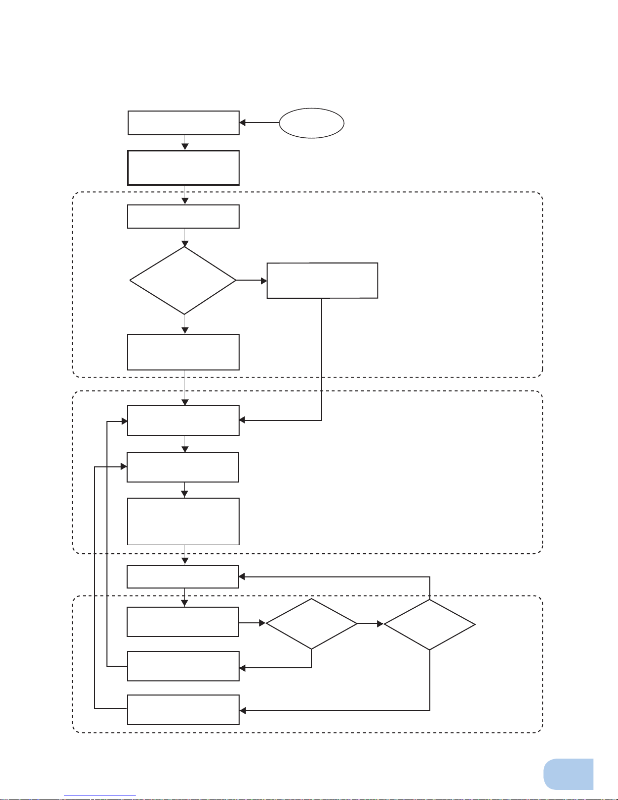
Procedure from installation to operation
Start
Installation/connection
Preparation for operation
Maintenance/
inspection
Ye s
No
No
Ye s Ye s
No
Read “Safety precautions”
Page v
Remove the product from the
package and check the contents
Page 1
Perform installation and
connection Page 5
Check the operation and
displays Pages 22
Charge the battery
Page 24
Measure the backup time
Page 24
Read “Using the UPS
monitoring software and
contact signal” Page 58
Operate Page 25
Deteriorated
battery?
Fan stopped?
Perform maintenance
and inspection Page 45
Replace the battery
Page 46
Replace the fan
Page 55
Are you
using UPS monitoring
software or contact
signal?
Charge the battery again
Page 24
* Preparation for operation is
complete.
Page 5

Table of Contents
iv
Table of Contents
Introduction ..........................................................................................................................................i
IMPORTANT SAFETY INSTRUCTION .............................................................................................. ii
Safety precautions .............................................................................................................................. v
1. Preparation .....................................................................................................................................1
1-1 Unpacking the product .......................................................................................................................... 1
1-2 Checking the contents ...........................................................................................................................1
1-3 Name of each part .................................................................................................................................2
1-4 Explanation of symbols used on unit .....................................................................................................4
2. Installation and connection .............................................................................................................5
2-1
Precautions and notes on installation and connection ......................................................................................................... 5
2-2 Installation and connection ....................................................................................................................9
2-3 Connecting the equipment .................................................................................................................. 15
2-4 Connecting the AC input...................................................................................................................... 18
2-5 Checking the operation ....................................................................................................................... 22
2-6 Charging the battery ............................................................................................................................24
2-7 Measuring the initial value of backup time .......................................................................................... 24
2-8 Recharging the battery ........................................................................................................................ 24
3. Operation ......................................................................................................................................25
3-1 Precautions and notes for operation ................................................................................................... 25
3-2
Start and stop procedures and basic operation ........................................................................................... 27
3-3
Interpreting beeps and displays ................................................................................................................... 30
4. UPS functions ...............................................................................................................................33
4-1 Suspending a beep ............................................................................................................................. 33
4-2 Self-diagnosis test ............................................................................................................................... 33
4-3 Description of the auto battery test function ........................................................................................ 34
4-4 Changing the setting of the functions .................................................................................................. 34
5. Measuring the backup time .......................................................................................................... 43
5-1 How to measure backup time ..............................................................................................................43
5-2 Estimated backup time ........................................................................................................................ 43
6. Maintenance and Inspection.........................................................................................................45
6-1 Checking the battery ........................................................................................................................... 45
6-2 Replacing the battery .......................................................................................................................... 46
6-3 Replacing the fan ................................................................................................................................ 55
6-4 Cleaning .............................................................................................................................................. 57
7. Using the UPS monitoring software and contact signal................................................................58
7-1 When using the included UPS monitoring software to perform auto shutdown .................................. 60
7-2 When performing auto-save functions using the UPS service in Windows Server 2003/XP/2000 +
UPS service driver .............................................................................................................................. 63
7-3 When performing auto-save functions using the standard UPS service in Windows Server 2003/
XP/2000/NT ......................................................................................................................................... 64
7-4 Contact signal...................................................................................................................................... 70
8. Using an SNMP/Web card ............................................................................................................ 78
8-1 Adding an SNMP/Web card ................................................................................................................ 78
8-2 SNMP/Web card outline ...................................................................................................................... 79
9. Extending the backup time ...........................................................................................................80
9-1 Connecting an additional battery unit .................................................................................................. 80
10. Troubleshooting .......................................................................................................................... 82
References .......................................................................................................................................83
A. Specifi cations ........................................................................................................................................83
B. Dimensions ............................................................................................................................................ 84
C. Circuit block diagram ............................................................................................................................. 86
D. Related products ................................................................................................................................... 86
Page 6
BU75RW/BU100RW/BU200RWBU300RW
v
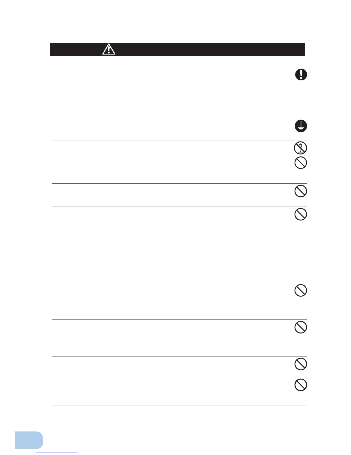
: Indicates prohibition. For example, indicates that disassembly is prohibited.
: Indicates obligation. For example,
indicates that grounding is necessary.
Misuse may cause death or serious injury.
Warning
Caution
Safety precautions
●
The safety symbols and their meaning used in this manual are as follows:
* Property damage means damage to houses/household effects, livestock, and pets.
Note that events categorized as a caution required matter also may cause more serious results under
certain conditions.
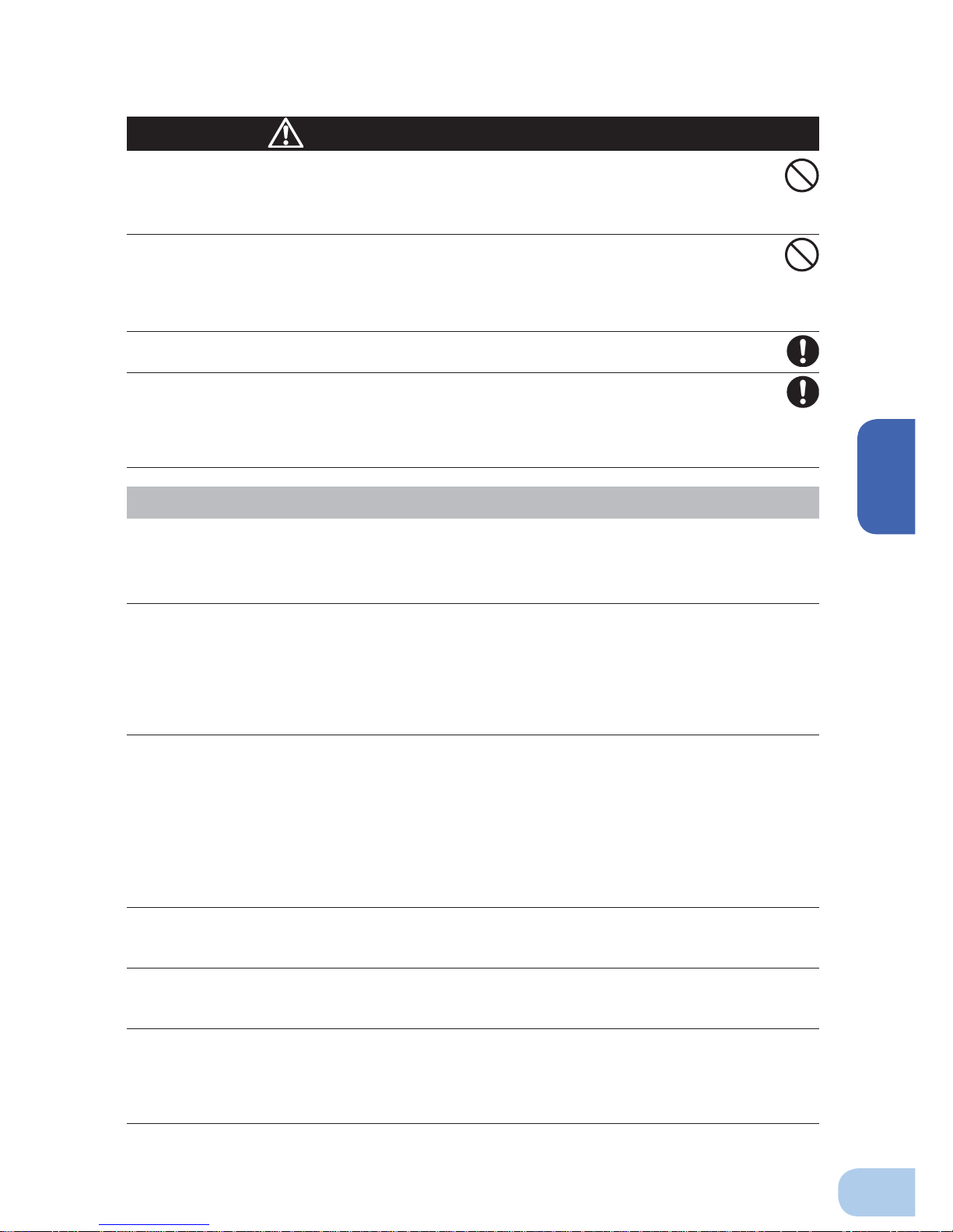
Do not use this unit when very high reliability and safety are required as
listed below. This unit is designed and manufactured for use with FA or
OA equipment such as personal computers.
●
Medical equipment or system that may cause death directly.
●
Applications that directly affect the safety of people (For example, the operation and control of
cars and elevators).
●
Applications in which a failure of the unit may cause signifi cant damage to the society and public
(For example, essential computer systems and main communication equipment.)
●
Applications with the same level of import
ance.
Warning
Important information for safe operation is described.
Be sure to read it before installation and start of use.
Misuse may cause injury or property damage.
Two or more people should work together to carry, unpack and install.
●
Because the unit is heavy, you may injure yourself or drop the unit, or it may fall over.
Carry the unit considering its weight and balance, and place it on a stable
and robust base.
●
Dropping or toppling the unit may cause injury.
●
The approximate weights of the units are 20kg (BU75RW/BU100RW) and 33kg (BU200RW/
BU300RW).
●
If you drop the unit, stop using it and have it inspected and repaired.
For repair, contact us; ____
Keep plastic package bags out of reach of children.
●
Children may suffocate if they place their heads into plastic bags.
Make sure to connect the unit’s AC input plug to a commercial power
source with rated input voltage (100 VAC) and 50/60Hz frequency.
●
Connecting to a commercial power source with a different rated input voltage or frequency may
result in a fi re.
●
The unit may fail.
Caution
(for installation and connection)
Page 7
Safety precautions
vi
When an abnormality (unusual sound or smell) occurs, turn OFF the
unit’s power switch to stop the output, and stop the supply of commercial
power.
For the BU75RW/BU100RW, disconnect the AC input plug from the wall
outlet. For the BU200RW/BU300RW, disconnect the AC input plug from
the wall outlet (commercial power) or turn OFF the INPUT PROTECTION
switch (input overcurrent protection switch) on the back of the unit.
●
When performing maintenance on the connected devices, follow the above instructions to
ensure safety.
Do not connect devices such as dryers, some solenoid valves, etc. ,
which have a half-wave rectifi er that allows only half-cycle AC power to
fl ow through.
●
Overcurrent may damage the UPS.
Connect the unit to a wall outlet (commercial power) with the appropriate
capacity (10A or greater for BU75RW, 12A or greater for BU100RW, 24A or
greater for BU200RW, and 35A or greater for BU300RW).
●
Otherwise, the power cord may be heated.
●
When equipment with the maximum output capacity is connected, a maximum current of 10A
(BU75RW),12A (BU100RW), 24A (BU200RW) or 35A (BU300RW) fl ows.
When using the 15A plug (NEMA 5-15P) that is connected to the BU200RW
at shipment, the maximum capacity connectable to the output is
approximately 1100VA/880W.
●
When the power consumption exceeds this capacity, the input voltage becomes larger than 20A,
which may lead to overheating or fi re. .
●
If the “overload” display appears, switch to a 30A plug or connect to a power switchboard with a
power capacity of 24A or more.
When using the 30A plug (NEMA L5-30P) that is connected to the
BU300RW at shipment, the maximum capacity connectable to the output
is approximately 2400VA/1920W.
●
When the power consumption exceeds this capacity, the input voltage becomes larger than 30A,
which may lead to overheating or fi re.
●
If “OVER LOAD” is displayed, connect to a power switchboard with a power capacity of 35A or
more.
When changing the input cable for the BU200RW and BU300RW, make
sure to perform the connection as specifi ed. Make sure to properly match
the AC input terminal with the appropriate wire color.
Do not perform work on the AC input terminal while BU300RW is
connected to a commercial power source.
●
Refer to “2-4 Connecting the AC input” on page 16.
●
Failure to do so may result in electric shock or ground fault.
Provide secure grounding.
●
After checking the plug shape of the wall outlet, directly connect the AC input plug of the unit to it. A
failure or leak that occurs when the unit is not properly grounded may result in electric shock.
Do not disassemble, repair, or modify the unit.
●
Doing so may cause an electric shock or a fi re.
Do not install the unit in other than specifi ed orientations.
●
Dropping or toppling the unit may cause injury.
●
If you install the unit in an orientation other than specifi ed, the unit cannot be protected from a
battery fl uid leakage.
●
Use the included vertical stand when positioning the unit vertically.
Caution
(for installation and connection)
Page 8
BU75RW/BU100RW/BU200RWBU300RW
vii
Do not use the unit where the maximum temperature exceeds 40°C.
●
The battery deteriorates rapidly.
●
Doing so may cause a failure or malfunction of the unit.
Do not exceed the ranges specifi ed for environmental conditions during
use/storage.
Do not install or store the unit in the places listed below.
●
Do not store in places where the humidity is lower than 10% or higher than 90%.
●
Do not use the unit in places where the ambient temperature is lower than 0°C or higher than
40°C.
●
Do not use in places where the humidity is lower than 25% or higher than 85%.
●
Do not install/store the unit in closed places such as cabinets with no clearance, places where
there is fl ammable or corrosive gas, places with large amounts of dust, places exposed to direct
sunlight, places exposed to shock or vibration, or outdoors.
●
Installation or storing the unit in such a place may cause a fi re.
Do not connect equipment that exceeds the output capacity of the unit.
You can use plug strip to connect additional devices, but do not connect
devices that exceed the current capacity of the plug strip.
●
The current protection of the unit may operate, which may stop the output.
●
The wiring of the plug strip heats up, which may cause a fi re.
Do not pinch or sharply bend the cable.
Do not fold or knot the cable.
●
Doing so may cause the cable to be damaged or heated, which may cause an electric shock or a fi re.
●
If the cable is damaged, stop using the unit and have the cable repaired.
●
For repair, contact us; ____
All of the included accessories are designed to be used exclusively with
the unit. Do not use the accessories with other devices.
●
Doing so may compromise the safety of devices.
Do not block the air vents (front and rear).
●
Doing so will cause the internal temperature to rise, which may cause the unit to fail and the bat-
tery to deteriorate.
●
Leave at least 5 cm of space between the vent and the wall.
Do not connect a standalone transformer such as a voltage transformer
or isolating transformer to the output side.
●
Overcurrent may damage the UPS or cause it to malfunction.
●
There is no problem in connecting a transformer to the input side.
Do not connect devices that cannot be used with commercial power
supply.
●
When the unit’s power switch is turned ON and an error occurs with the connected device, by-
pass operation is performed and commercial power supply is supplied as is to the connected
devices.
When installing the unit on a rack, place it on the lowest shelf.
●
Injury may result if the unit falls.
Make sure to use the mounting screws included with the brackets.
●
Mounting screws other than those included may not be strong enough to support the unit, caus-
ing it to fall.
●
If you attach the case using long screws other than those included with the product, you may
damage the internal parts of the unit.
Caution
(for installation and connection)
Page 9
Safety precautions
viii
Do not allow the unit to come in contact with water.
If you drop the unit, stop using it.
●
Doing so may cause an electric shock or a fi re.
●
If the unit becomes wet or is dropped, immediately stop using it, disconnect the AC input plug
from the wall outlet (commercial power) or, when using the BU200RW/BU300RW, turn OFF the
INPUT PROTECTION switch (input overcurrent protection switch) on the back of the unit, and
have it inspected and repaired.
●
For repair, contact us; ____.
When the battery is dead, replace it immediately or stop using the unit.
●
Continuing the use of it may cause a fi re.
Using a dry cloth, periodically wipe the dust from the AC input plug, input
terminal block and power supply output receptacles.
●
Accumulated dust may cause a fi re.
Do not use the unit in a closed place and do not cover the unit.
●
Doing so may cause abnormal heating or a fi re.
If you notice an abnormal sound or smell, smoke, or leaking fluid,
immediately turn OFF the unit’s power switch and stop the supply of
commercial power.
(For the BU75RW/BU100RW, disconnect the AC input plug from the wall
outlet. For the BU200RW/BU300RW, disconnect the AC input plug from
the wall outlet (commercial power) or turn OFF the INPUT PROTECTION
switch (input overcurrent protection switch) on the back of the unit.)
●
Using the unit under such conditions may cause a fi re.
●
If you notice such a condition, stop using the unit and contact us at _____ for inspection and repairs.
●
Position the unit in such a way that you can immediately disconnect the AC input plug from
the wall outlet (commercial power) in the event a problem occurs, and if using the BU200RW/
BU300RW, position it so that you can turn OFF the INPUT PROTECTION switch (input overcurrent protection switch) on the back of the unit.
If fl uid leaks from the unit, do not touch the fl uid.
●
Doing so may cause blindness or burns.
●
If the fl uid contacts your eyes or skin, wash it out with lots of clean water and consult your doctor.
Do not place objects heavier than 25kg on the unit, and do not drop heavy
objects onto the unit.
●
Doing so may cause distortion/damage to the case or a failure of the internal circuit, which may
cause a fi re.
BU300RW is equipped with a bypath circuit which is able to supply
electric power to connected devices even when the inner control circuit is
broken down by defects or malfunctions
●
Output is continuing even when all indicators of the front panel are off.
●
If you want to stop the output, either stop the source of commercial power, disconnect the AC
input plug from the wall outlet (commercial power) or, if using the BU200RW/BU300RW, turn
OFF the input overcurrent protection switch (INPUT PROTECTION switch) on the back of the
unit
Ambient temperature Expected life
20°C 4 to 5 years
30°C 2 to 2.5 years
* The values in the table are the expected life under stan-
dard use conditions and are not guaranteed.
Caution
(for use)
Page 10
BU75RW/BU100RW/BU200RWBU300RW
ix
When maintaining the connected equipment, turn OFF the unit’s power
switch to stop the output, and stop the supply of commercial power.
(For the BU75RW/BU100RW, disconnect the AC input plug from the wall
outlet. For the BU200RW/BU300RW, disconnect the AC input plug from
the wall outlet (commercial power) or turn OFF the INPUT PROTECTION
switch (input overcurrent protection switch) on the back of the unit.)
●
Even if commercial power to the UPS is stopped while it is in operation, the power output of
this unit does not stop and power is supplied from the receptacle.
Do not disassemble, repair, or modify the unit.
●
Doing so may cause an electric shock or a fi re.
If fl uid leaks from the unit, do not touch the fl uid.
●
Doing so may cause blindness or burns.
●
If the fl uid contacts your eyes or skin, wash it out with lots of clean water and consult your doctor.
Do not throw the unit into fi re.
●
The lead battery in the unit may explode, or leak dilute sulfuric acid.
Do not insert metal objects into the power supply output receptacle of the
UPS.
●
Doing so may result in electric shock.
Do not insert metal objects into the battery connectors.
Do not create a short between the connector terminals.
●
Doing so may result in electric shock.
Perform replacement on a stable and fl at place.
●
Handle the battery carefully so that you do not drop it.
●
Not doing so could cause injury or burns due to liquid (acid) leakage.
Use a specifi ed battery for replacement.
●
Not doing so may cause a fi re.
●
Replacement battery pack for BU75RW/BU100RW: BUB100R
Replacement battery pack for BU200RW/BU300RW: BUB300R
Do not replace the battery in a place where there is fl ammable gas.
●
Spark may occur when connecting the battery, which may cause an explosion or fi re.
If fl uid (dilute sulfuric acid) leaks from the battery, do not touch the fl uid.
●
Doing so may cause blindness or burns.
●
If it contacts your eyes or skin, wash it out with lots of clean water and consult your doctor.
Do not disassemble or modify the battery.
●
Doing so could cause dilute sulfuric acid leak, which could cause blindness and burns.
Do not drop the battery and do not expose it to strong impact.
●
Dilute sulfuric acid may leak.
Do not short the battery with metal objects.
●
Doing so could cause an electric shock, fi re or burn.
●
Some electrical energy still remains inside the spent battery.
Do not put the battery into fi re and do not break it.
●
The battery may explode or leak dilute sulfuric acid.
Do not use a new battery and an old battery at the same time.
●
Dilute sulfuric acid may leak.
Caution
(for maintenance)
Caution
(for battery replacement)
Page 11

Safety precautions
x
Notes
When moving the unit from a cold place to a warm place, leave it for several
hours before using it.
●
If the unit is promptly turned ON after being moved to a warmer place, condensation may form inside the
unit and cause it to fail.
Charge the battery for at least 8 hours soon after purchasing the unit.
●
If you do not use the unit for a long time after the purchase, the battery may deteriorate and the battery
may become unusable.
●
For the BU75RW/BU100RW, the battery can be charged once the AC input plug is connected to commer-
cial power. For the BU200RW/BU300RW, the battery can be charged once the plug is connected to commercial power and the INPUT PROTECTION switch (input overcurrent protection switch) is turned ON.
Recharge the battery for at least 8 hours every 6 months when the storage
temperature is 25°C or less, or every 2 months when the storage temperature is
40°C or less.
●
The battery self-discharges even when it not being used, and it goes into over-discharge state if it is left
for a long period of time. The backup time may become shorter or the battery may become unusable.
●
We recommend keeping the temperature 25°C or less when storing the unit for long periods of time.
●
Turn OFF the unit’s power switch when storing it.
●
Before storing an additional battery, charge it for at least 24 hours.
Do not short the output lines of the unit to each other, and do not short the
output lines to the ground.
●
The unit may fail.
Do not connect the AC input plug of the unit to its Power Supply Output
Receptacle during the Battery Mode.
●
The unit may fail.
Do not connect a page printer (such as a laser printer) to the unit.
●
The unit repeatedly and frequently switches between Commercial Power Mode and Battery Mode, which
may shorten the life of the battery.
●
The page printer has a large peak current, so an excess of the connection capacity or a power failure due
to instantaneous voltage drop may be detected.
Check system operation beforehand if the unit is used in combination with a
device whose power supply frequency fluctuates widely, such as a personal
electric generator.
●
The unit automatically recognizes the input power frequency when input power is supplied.If the unit is
connected when the input power frequency is not stable at the rated level, the unit may misidentify the
power supply frequency and may fail to operate normally. (If the unit is in operation, changing from com-
mercial power supply to another power supply source, such as generating equipment, will cause no problem. Set the generator's frequency to the same level as that of the commercial power supply.)
Do not install or store the unit in a place exposed to direct sunlight.
●
The rise of temperature may cause the built-in battery to deteriorate rapidly and become unusable.
Before performing a withstand voltage test or insulation resistance test, make
sure to remove the input surge protection GND screw from the back of the unit.
When in use, make sure the input surge protection GND screw is securely
fastened.
●
Performing the withstand voltage test with the ground wire connected may damage the surge absorption
element built into the power supply input circuit.
Page 12
BU75RW/BU100RW/BU200RWBU300RW
xi
Explanation
Usual operation
●
You may either leave the power switch of the unit ON (operation status) or turn it OFF each time when
stopping the connected system. Choose whichever operation method is more convenient. We recommend
turning OFF the power switch when you do not use connected devices for a long time.
●
For the BU75RW/BU100RW, the battery can be charged once the AC input plug is connected to a com-
mercial power source. For the BU200RW/BU300RW, the battery can be charged once the plug is connected and the INPUT PROTECTION switch (input overcurrent protection switch) is turned ON.
Quitting Battery Mode
●
If a power failure lasts for an extended period of time, the battery discharges and power output from the
unit stops. Shut down your computer after performing appropriate procedures (for example, saving data)
while the unit is still supplying power.
Rebooting
●
If the battery discharges completely during a power failure, the output stops. After recovery from the
power failure, the unit automatically restarts and output begins. If you do not want to restart the connected
devices, turn OFF the power switch of either the unit or the connected devices.
See also
Setting switch 2 can be used to select whether or not auto restart is performed. See Page 35
Scheduled operation using the UPS monitoring software
●
When performing scheduled operation in which the UPS is stopped and a device such as a breaker is
used to stop the UPS at the same time that commercial power stops, specify a period of no more than 3
months for the start of the next operation.
If you specify a period longer than 3 months, the internal timer is reset and the scheduled operation does
not start. Note that this period reduces to approximately half when the battery is dead. If a period of 3
months is exceeded, you start operation by supplying commercial power and pressing the start switch.
However, if the battery is dead, you may not be able to start operation.
In this case, replace the battery according to the instructions in “6-2 Replacing the battery” on page 46.
Pb
Notes
Before stopping the commercial power to the unit, turn OFF the power switch of
the unit.
●
The unit enters Battery Mode when commercial power is stopped. If you frequently use the unit in Battery
Mode, the battery life may be signifi cantly shortened.
If this unit is used with an inductive device such as a coil or motor, check the
operation beforehand.
●
With some types of devices, the effect of inrush current may cause this unit to stop operating properly.
In the event you transfer or sell this unit to a third party, please include all of the
documentation that came with the unit. This is to ensure that the unit is used in
line with the conditions described in the included documentation.
●
This manual contains important safety-related information. Please read and understand the contents of
the manual before beginning operation.
This unit uses lead acid batteries,
●
Which are a valuable recyclable resource. Please recycle.
Take measures for handling unforeseen accidents, such as data backup and
system redundancy.
●
The output may stop when there is a circuit failure in the UPS.
Page 13
1
1
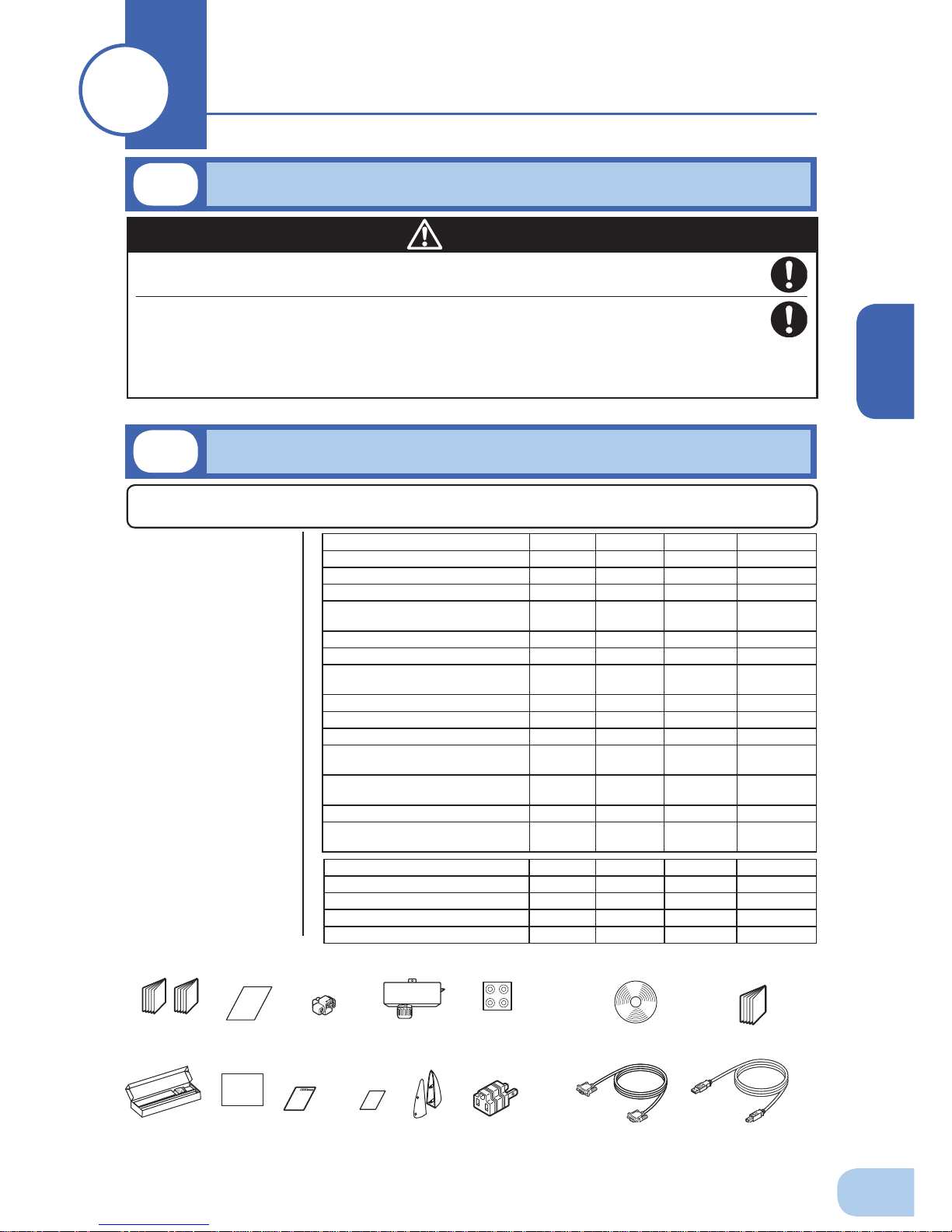
Open the package box and take out the UPS and accessories.
Two or more people should work together to carry, unpack and install.
●
Because the unit is heavy, you may injure yourself or drop the unit, or it may fall over.
Product weights are 20kg (BU75RW/BU100RW) and approximately
33kg (BU200RW/BU300RW).
Unpack/transport this product considering this weight.
●
Dropping may cause injury.
Caution
Instruction manual
(Japanese/English
edition)
Label (How to
determine
operating status)
User registration
card
Connector
for remote
ON/OFF
Terminal block cover
for BU200RW/
BU300RW (with
cable clamp)
Warranty
OMRON
contact
info label
Rubber feet
(For horizontal installation:
14.5 mm depth)
(For upright installation:
1.7 mm depth)
EIA/JIS 19-inch rack
mount support angles
Vertical stand
3P-2P
conversion
plug
CD-ROM
Connection cable(USB)
(Approx. 2.2 m)
<Accessories related to main unit> <UPS monitoring software>
Connection cable(RS-232C)
(Approx. 2.2 m)
1-1
Unpacking the product
Preparation
11
1-2
Checking the contents
Check whether all the package contents are included and there is no damage found on their appearance.
If you should notice defects or anything wrong, contact us; ____
(1)
Accessories
related to the
main unit
(2) UPS
monitoring
software
related items
Quick installation
guide
BU75RW
BU100RW BU200RW BU300RW
Instruction manual (Japanese/English) 1 each 1 each 1 each 1 each
Warranty card 1 1 1 1
User registration card 1 1 1 1
Label (How to determine operating
status)
11 1 1
Remote ON/OFF connector 1 1 1 1
Vertical stand 2 per set 2 per set 2 per set 2 per set
Support angles compatible with EIA/
JIS 19-inch racks
1 set 1 set 1 set 1 set
Omron contact info label 1 1 1 1
Battery replacement date label 1 1 1 1
Control display panel explanation label 1 1 1 1
Rubber feet for horizontal placement
(14.5mm thick)
4 per set 4 per set 4 per set 4 per set
Rubber feet for vertical placement
(1.7mm thick)
6 per set 6 per set 6 per set 6 per set
3P-2P conversion plug 1 1 1 Terminal block cover (with cable
clamp)
-- 1 1
*1 Do not use 3P-2P conversion plug when the unit is used in
compliance with UL standard or CE marking.
BU75RW BU100RW BU200RW BU300RW
Quick Install Guide 1 1 1 1
CD-ROM 1 1 1 1
Connection cable (RS232C) 1 1 1 1
Connection cable (USB) 1 1 1 1
Page 14
1.Preparation
2
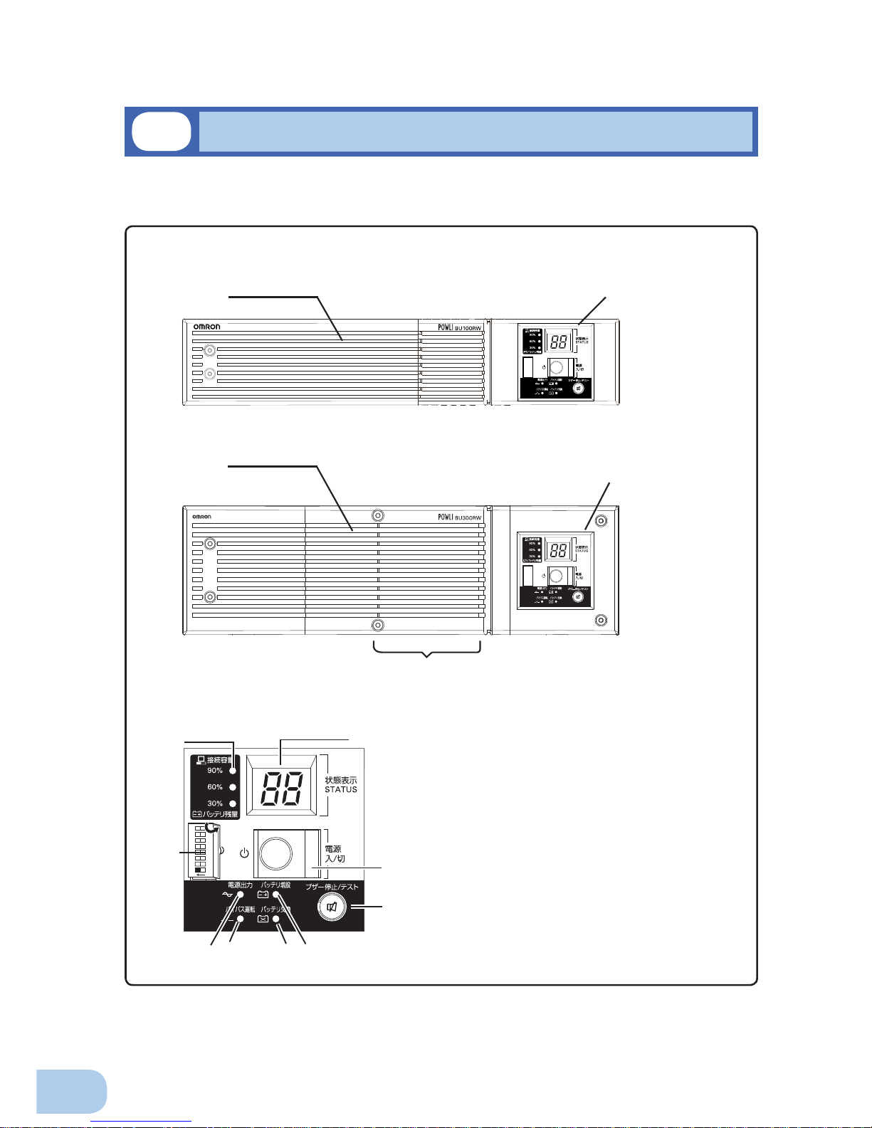
This section describes the name of each part of the UPS.
For information on the function of each part, refer to "2. Installation and connection" on page 5 and
"3. Operation" on page 25 that provides the details.
Front view
< Enlarged view of the display panel >
A. Status indicator digital display
B. Power switch
C. Beep stop/test switch
D. Battery addition lamp
E. Battery replacement lamp
F. Bypass operation lamp
(The input power supply is output as is.)
G. Power supply output lamp
H. Setting switch cover/Setting switches
I. Connection capacity/battery level meter
ON DIP
1 2
567
8
3 4
A
I
B
C
H
E
D
G F
<BU75RW/BU100RW>
<Control display panel>
<Air vent>
1-3
Name of each part
<Front cooling fan (intake) >
<Control display panel>
<BU200RW/300RW> (Image shows BU300RW)
<Air vent>
Page 15
BU75RW/BU100RW/BU200RW/BU300RW
1
3
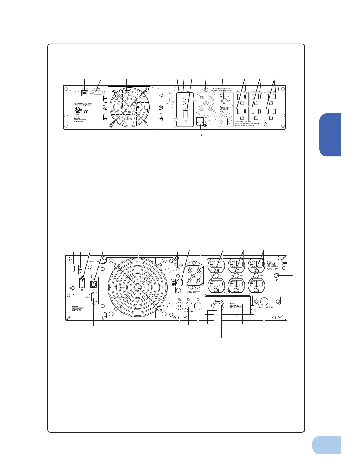
Rear view
C HDF
E
BA G I
J K L
N
M
O
QRS
P
A. Contactsignalcard
B. RemoteON/OFFconnector
C. Contactsignalconnector
D. USBconnector
E. RS-232Cconnector
F. Rearcoolingfan(exhaust)
G. InputsurgeprotectionGND
H. Additionalbatterysignalconnector
I. Additionalbatteryconnector
J. PowersupplyoutputreceptacleA
K. PowersupplyoutputreceptacleB
L. PowersupplyoutputreceptacleC
M. Groundingterminal
N. ACinputovercurrentprotection
switch45A
O. TerminalCover
P. ACinputcable
Q. PowersupplyoutputreceptacleC
overcurrentbreaker(20A)
R. PowersupplyoutputreceptacleB
overcurrentbreaker(20A)
S. PowersupplyoutputreceptacleA
overcurrentbreaker(20A)
<BU200RW/BU300RW>
<BU75RW/BU100RW>
C
D E F H
M
NO
I JG
BA
K L
A.USBconnector
B.RS-232Cconnector
C.Coolingfan
D.InputsurgeprotectionGND
E.Contactsignalcard
F.Remote ON/OFFconnector
G.Contactsignalconnector
H.Additionalbatteryconnector
I. ACinputovercurrentprotectionswitch
INPUTPROTECTION15A
J.PowersupplyoutputreceptacleA
K.PowersupplyoutputreceptacleB
L.PowersupplyoutputreceptacleC
M.Groundingterminal
N.ACinputcable
O.Additionalbatterysignalconnector
Page 16
1.Preparation
4
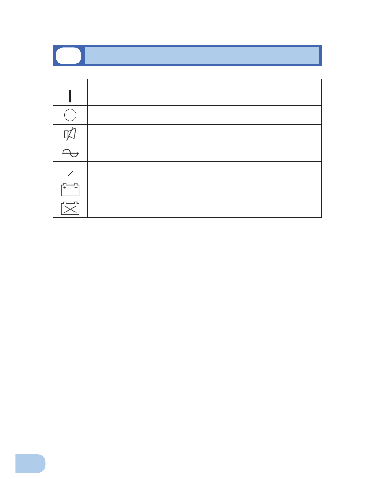
1-4
Explanation of symbols used on unit
Symbol Description
Start the UPS.
Stop the UPS.
Suspend a beep.
UPS output power enabled, supplied by operating on line mode, battery mode.
Bypass output “ON”.
Additional battery unit connected to the UPS.
Batteries at end of useful life, necessary to replace the batteries.
Page 17
2
5
Two or more people should work together to carry, unpack and install the
BU200RW/BU300RW.
●
Because the unit is heavy, you may injure yourself or drop the unit, or it may fall over.
Carry the unit considering its weight and balance, and place it on a stable
and robust base.
●
Dropping or toppling the unit may cause injury.
●
The approximate weights of the units are 20kg (BU75RW/BU100RW) and 33kg (BUU200RW/
BU300RW).
●
If you drop the unit, stop using it and have it inspected and repaired.
For repair, contact us; ____
Do not hold the side of the front panel when lifting.
●
Injury may result if the panel comes off and falls.
Keep plastic package bags out of reach of children.
●
Children may suffocate if they place their heads into plastic bags.
Make sure to connect the unit’s AC input plug to a commercial power
source with rated input voltage (100 VAC) and 50/60Hz frequency.
●
Connecting to a commercial power source with a different rated input voltage or frequency may
result in a fi re.
●
The unit may fail.
When an abnormality (unusual sound or smell) occurs, turn OFF the
unit’s power switch to stop the output, and stop the supply of commercial
power.
For the BU75RW/BU100RW, disconnect the AC input plug from the wall
outlet. For the BU200RW/BU300RW, disconnect the AC input plug from
the wall outlet (commercial power) or turn OFF the INPUT PROTECTION
switch (input overcurrent protection switch) on the back of the unit.
●
When performing maintenance on the connected devices, follow the above instructions to en-
sure safety.
Do not connect devices such as dryers, some solenoid valves, etc. ,
which have a half-wave rectifi er that allows only half-cycle AC power to
fl ow through.
●
Overcurrent may damage the UPS.
Connect the unit to a wall outlet (commercial power) with the appropriate
capacity (10A or greater for BU75RW, 12A or greater for BU100RW, 24A or
greater for BU200RW, and 35A or greater for BU300RW).
●
Otherwise, the power cord may be heated.
●
When equipment with the maximum output capacity is connected, a maximum current of 10A
(BU75RW), 12A (BU100RW), 24A (BU200RW) or 35A (BU300RW) fl ows. .
When using the 15A plug (NEMA 5-15P) that is connected to the BU200RW
at shipment, the maximum capacity connectable to the output is
approximately 2000VA/1600W.
●
When the power consumption exceeds this capacity, the input voltage becomes larger than 20A,
which may lead to overheating or fi re.
●
If the “overload” display appears, switch to a 30A plug or connect to a power switchboard with a
2-1
Precautions and notes on installation and connection
Installation and connection
22
Caution
(for installation and connection)
Page 18
2.Installation and connection
6
power capacity of 24A or more.
When using the 30A plug (NEMAL5-30P) that is connected to the
BU300RW at shipment, the maximum capacity connectable to the output
is approximately 2400VA/1920W.
●
When the power consumption exceeds this capacity, the input voltage becomes larger than 30A,
which may lead to overheating or fi re.
●
If “OVER LOAD” is displayed, connect to a power switchboard with a power capacity of 35A or
more.
Provide secure grounding.
●
After checking the plug shape of the wall outlet, directly connect the AC input plug of the unit to it.
A failure or leak that occurs when the unit is not properly grounded may result in electric shock.
Do not disassemble, repair, or modify the unit.
●
Doing so may cause an electric shock or a fi re.
Do not install the unit in other than specifi ed orientations.
●
Dropping or toppling the unit may cause injury.
●
If you install the unit in an orientation other than specifi ed, the unit cannot be protected from a
battery fl uid leakage.
Do not use the unit where the maximum temperature exceeds 40°C.
●
The battery becomes weak rapidly, which may cause a fi re.
●
Doing so may cause a failure or malfunction of the unit.
Do not exceed the ranges specifi ed for environmental conditions during
use/storage.
Do not install or store the unit in the places listed below.
●
Do not store in places where the humidity is lower than 10% or higher than 90%.
●
Do not use the unit in places where the ambient temperature is lower than 0°C or higher than
40°C.
●
Do not use in places where the humidity is lower than 25% or higher than 85%.
●
Do not install/store the unit in closed places such as cabinets with no clearance, places where
there is flammable or corrosive gas, places with large amounts of dust, places exposed to
direct sunlight, places exposed to shock or vibration, or outdoors.
●
Installation or storing the unit in such a place may cause a fi re.
Do not connect equipment that exceeds the output capacity of the unit.
You can use a plug strip to connect additional devices, but do not connect
devices that exceed the current capacity of the plug strip.
●
The current protection of the unit may operate, which may stop the output.
●
The wiring of the plug strip heats up, which may cause a fi re.
Do not pinch or sharply bend the cable.
Do not fold or knot the cable.
●
Doing so may cause the cable to be damaged or heated, which may cause an electric shock or a fi re.
●
If the cable is damaged, stop using the unit and have the cable repaired.
For repair, contact us; ____
Do not use any of the included accessories with other devices.
●
The accessories are designed exclusively for use with this unit.
●
Doing so may compromise the safety of devices.
Do not block th e air vents (front and rear).
●
Doing so will cause the internal temperature to rise, which may cause the unit to fail and the bat-
tery to deteriorate.
●
Leave at least 5 cm of space between the vent and the wall.
Caution
(for installation and connection)
Page 19
BU75RW/BU100RW/BU200RW/BU300RW
2
7
Do not connect a standalone transformer such as a voltage transformer
or isolating transformer to the output side.
●
Overcurrent may damage the UPS.
●
There is no problem in connecting a transformer to the input side.
Do not connect devices that cannot be used with commercial power
supply.
●
When the unit’s power switch is turned ON and an error occurs with the connected device, by-
pass operation is performed and commercial power supply is supplied as is to the connected
devices.
When installing the unit on a rack, place it on the lowest shelf.
●
Injury may result if the unit falls.
Make sure to use the mounting screws included with the brackets.
●
Mounting screws other than those included may not be strong enough to support the unit, caus-
ing it to fall.
●
If you attach the case using long screws other than those included with the product, you may
damage the internal parts of the unit.
Notes
When moving the unit from a cold place to a warm place, leave it for several
hours before using it.
●
If the unit is promptly turned ON after being moved to a warmer place, condensation may form inside the
unit and cause it to fail.
Charge the battery for at least 8 hours soon after purchasing the unit.
●
The battery self-discharges even when it not being used, and it goes into over-discharge state if it is left
for a long period of time.
●
For the BU75RW/BU100RW, the battery can be charged once the AC input plug is connected to a com-
mercial power source. For the BU200RW/BU300RW, the battery can be charged once the plug is connected and the INPUT PROTECTION switch (input overcurrent protection switch) is turned ON.
●
When connecting an additional battery, charge it for at least 24 hours.
When storing the unit, charge the battery for at least 8 hours and turn OFF the
power switch.
●
Even if the unit is not used, the battery gradually discharges, and if it is left for a long time, it goes into an
over discharge state.
The backup time may become shorter or the battery may become unusable.
●
Connect the unit to a commercial power source every 6 months when the storage temperature is 25°C or
less, or every 2 months when the storage temperature is 40°C or less.
●
Turn off the power switch of the unit during storage.
●
Before storing an additional battery, charge it for at least 24 hours.
Do not short the output lines of the unit to each other, and do not short the
output lines to the ground.
●
The unit may fail.
Do not connect the AC input plug of the unit to its Power Supply Output
Receptacle during the Battery Mode.
●
The unit may fail.
Do not connect a page printer (such as a laser printer) to the unit.
●
The unit repeatedly and frequently switches between Commercial Power Mode and Battery Mode, which
may shorten the life of the battery.
●
The page printer has a large peak current, so an excess of the connection capacity or a power failure due
to instantaneous voltage drop may be detected.
Caution
(for installation and connection)
Page 20

2.Installation and connection
8
Notes
Check system operation beforehand if the unit is used in combination with a
device whose power supply frequency fluctuates widely, such as a personal
electric generator.
●
The unit automatically recognizes the input power frequency when input power is supplied.If the unit is
connected when the input power frequency is not stable at the rated level, the unit may misidentify the
power supply frequency and may fail to operate normally. (If the unit is in operation, changing from commercial power supply to another power supply source, such as generating equipment, will cause no prob-
lem. Set the generator's frequency to the same level as that of the commercial power supply.)
Do not install or store the unit in a place exposed to direct sunlight.
●
The rise of temperature may cause the built-in battery to deteriorate rapidly and become unusable.
Before performing a withstand voltage test or insulation resistance test, make
sure to remove the input surge protection GND screw from the back of the unit.
When in use, make sure the input surge protection GND screw is securely
fastened.
●
Performing the withstand voltage test with the ground wire connected may damage the surge absorption
element built into the power supply input circuit.
Before stopping the commercial power to the unit, turn OFF the power switch of
the unit.
●
The unit enters Battery Mode when commercial power is stopped. If you frequently use the unit in Battery
Mode, the battery life may be signifi cantly shortened.
If this unit is used with an inductive device such as a coil or motor, check the
operation beforehand.
●
With some types of devices, the effect of inrush current may cause this unit to stop operating properly.
Page 21
BU75RW/BU100RW/BU200RW/BU300RW
2
9
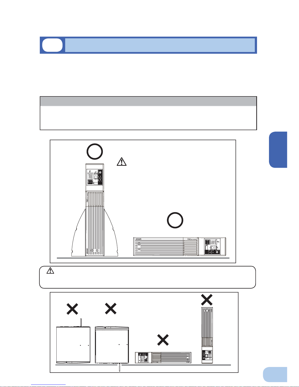
Do not use this unit in any position other than the “correct positions” indicated in the illustration below.
Note
Before installing this device, make a record of the serial number of this device.
The serial number is required when contacting us about the device.
The serial number (S/N) is inscribed on the bottom left side of the rear panel.
2-2
Installation and connection
< BU75RW/BU100RW >
CorrectPositions
iÊV>ÀivÕÊÌÊÌÊ}iÌÊÞÕÀÊv}iÀÃÊV>Õ}ÌÊ
ÜiÊ>ÀÀ>}}ÊÌiÊÕÌ°
IncorrectPositions
The UPS permits the following installing methods. Choose the one best suited for the environment.
2-2-1. Rackmount installation
2-2-2. Stationary installation
●
Horizontal
●
Upright intatllation
Caution
When connecting an additional battery unit (BUM100R), make sure it is installed below the
BU75RW/BU100RW UPS.
Page 22
2.Installation and connection
10
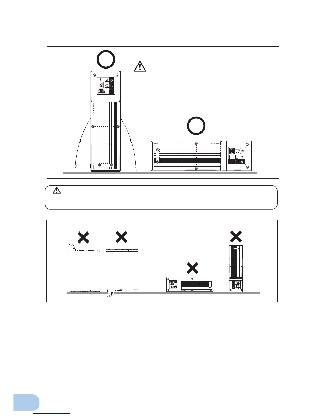
< BU200RW/BU300RW >
CorrectPositions
iÊV>ÀivÕÊÌÊÌÊ}iÌÊÞÕÀÊv}iÀÃÊV>Õ}ÌÊ
ÜiÊ>ÀÀ>}}ÊÌiÊÕÌ°
IncorrectPositions
Caution
When connecting an additional battery unit (BUM300R), make sure it is installed below the
BU200RW/BU300RW UPS.
Page 23
BU75RW/BU100RW/BU200RW/BU300RW
2
11
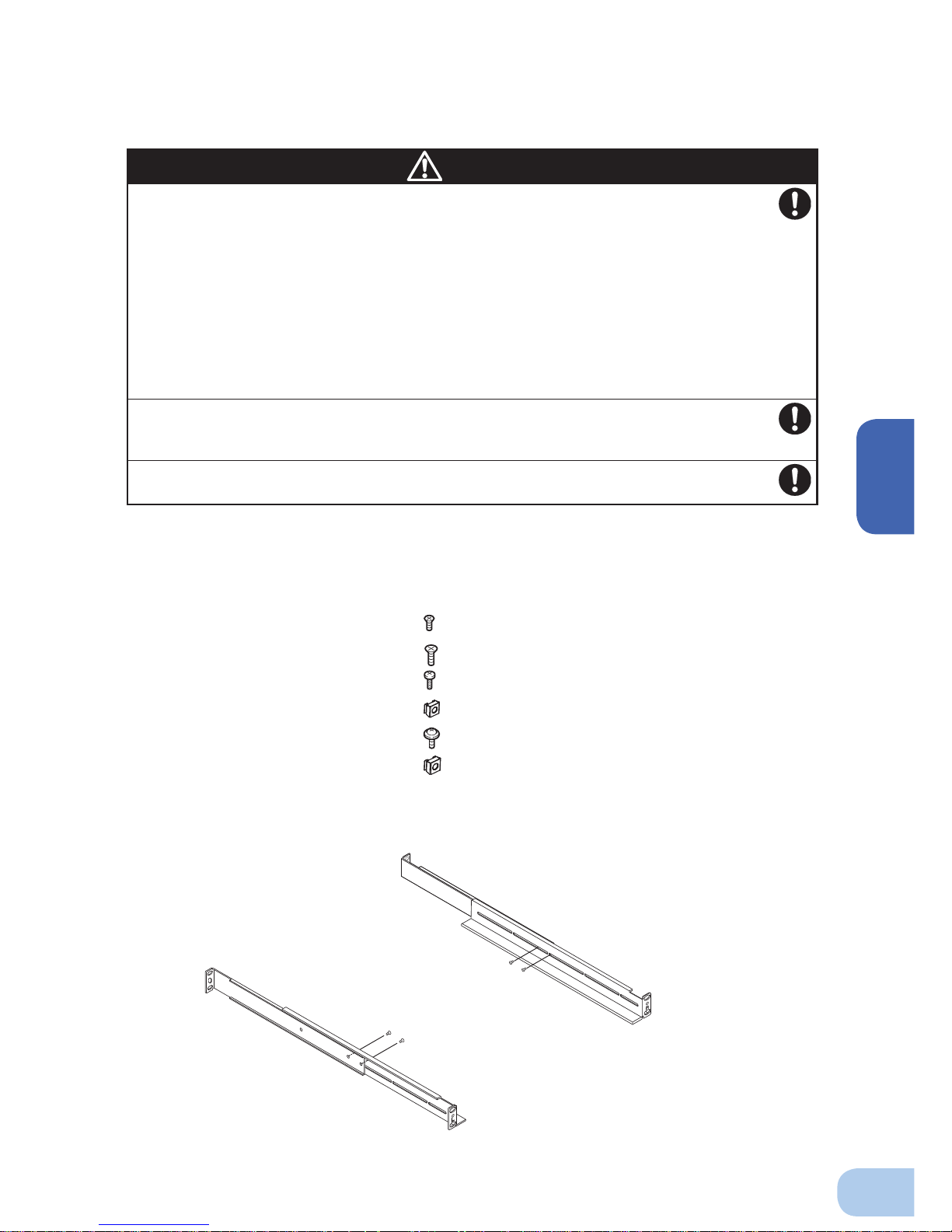
2-2-1. Rackmount installation (EIA /JIS 19-inch rack/server rack)
●
BU75RW/BU100RW/BU200RW/BU300RW rack mounting procedure
(1) Insert the 4 included rail length fi xing screws and half-tighten them to hold the front and
rear rack rails in place.
①
Caution
●
Items included in the 19-inch rack support angle mounting bracket set
4 rail length fixing screws (small)
Rack rail (front) L ....................................... 1
Rack rail (front) R ...................................... 1
Rack rail (rear) ........................................... 2
Ear brackets .............................................. 2
Rail length fixing screws (small) ................ 4
Ear bracket flush mounting screws (M4).... 8
Rack fixing screws (M5) ............................ 8
Rack fixing nuts (M5) ................................ 8
Unit fixing screws (M6) .............................. 2
Unit fixing nuts (M6) .................................. 2
When performing rack installation, ensure that the UPS is supported and
stabilized by using both the support angles and the table clamps that
were included.
When connecting a battery unit and/or adding another battery unit, be
sure to place the battery unit in a position lower than the main unit.
●
When installing on a rack, make sure that the UPS is supported by the each unit individually.
●
When installing on a rack, make sure to use the support angles and table clamps included with
the product. Without the support angles, the front clamp alone cannot support the weight of the
UPS.
●
The mass of the UPS: BU75RW/BU100RW: Approx. 20kg BUM100R: Approx. 26kg
BU200RW/BU300RW: Approx. 33kg BUM300R: Approx. 42kg
In a case where the UPS is to be mounted on a rack, place it on the
lowest part of the rack.
●
Dropping it may result in injury.
Be sure to use the supplied mounting screws.
●
Screws other than those supplied may not be strong enough to support the UPS, causing it to fall.
Page 24
2.Installation and connection
12
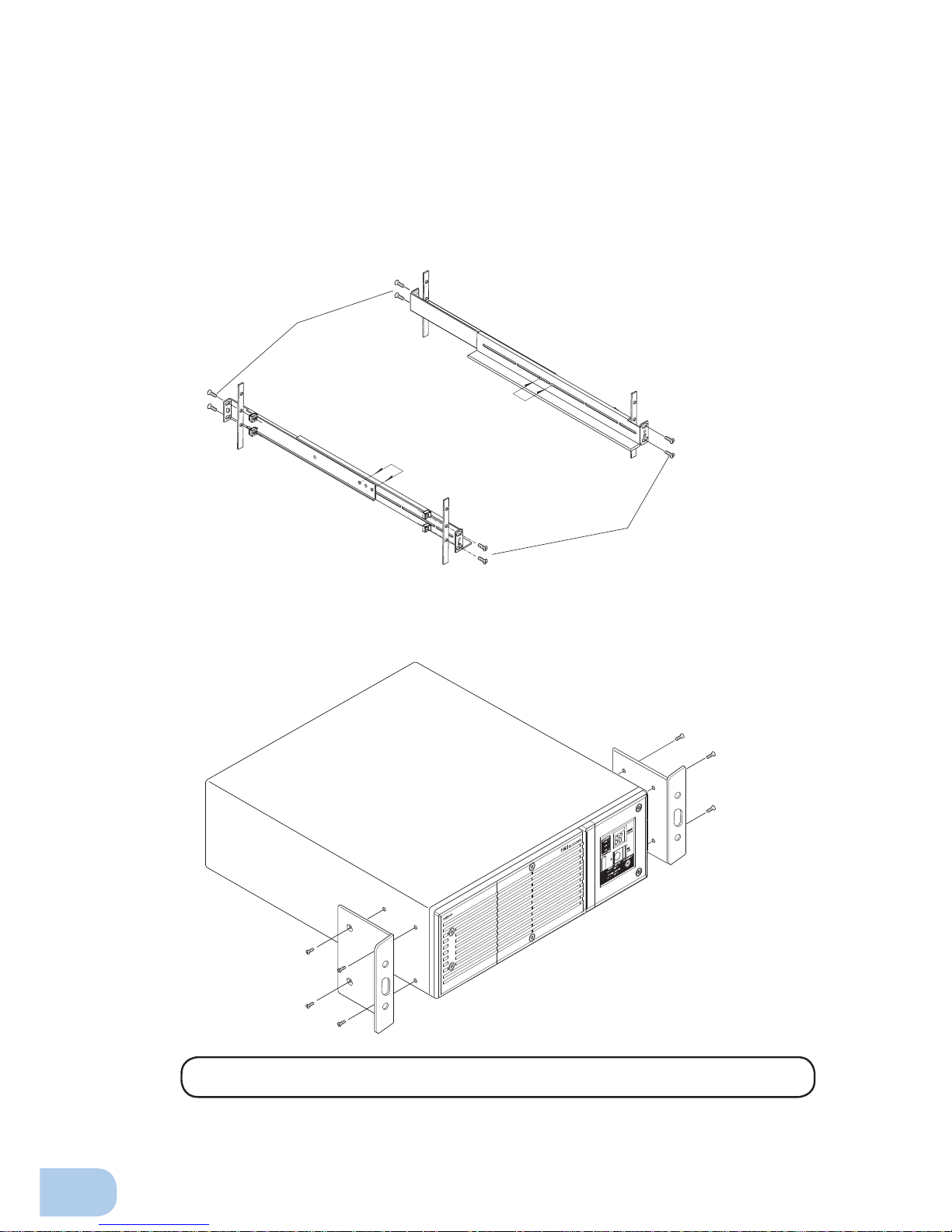
(3) Use the 4 included rack fi xing screws and nuts (medium-sized) to securely fasten the front
(the side displaying “L” or “R”) and back of the support angles to the server rack. (JIS stan
dards) ③
For JIS standards, use 4 sets of screws and nuts to fasten the left and right support angles
(one screw and nut at the back and front of each support angle) (middle screw holes). ③
(4) Use the 8 included ear bracket mounting screws (2 sets of 4 screws) to securely fasten the
ear brackets to the left and right sides of the UPS. ④
The support angles cannot be attached to special EIA/JIS racks.
(2) Adjust the length of support angles to suit the server rack, and then securely tighten the
screws that were half-tightened in step 1.
②
3
2
2
3
Rack fixing screws 8 (EIA standards)
4 (JIS standards)
Adjust the length to
suit the server rack
and tighten securely.
Ear bracket mounting screws
4
4
Page 25
BU75RW/BU100RW/BU200RW/BU300RW
2
13
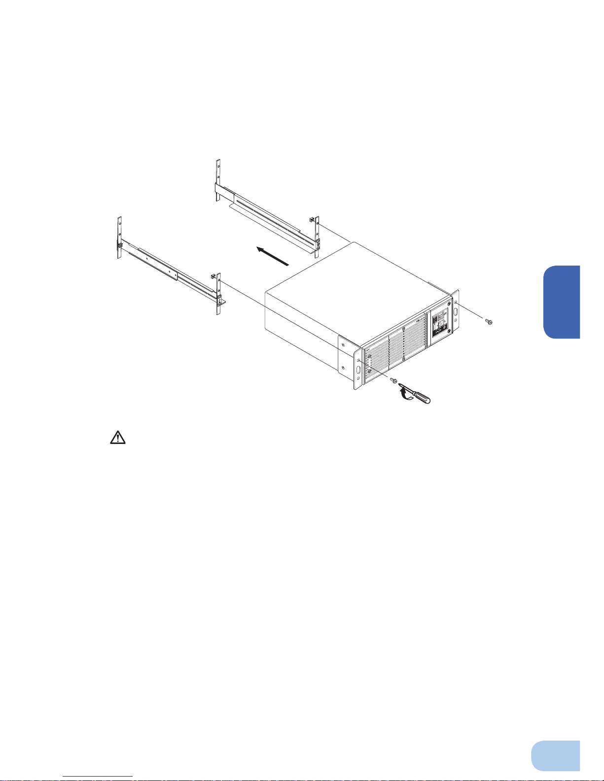
Always use the support angles.
(5) Place the UPS on the support angles and push it completely into the rack ⑤, and use the
2 included unit fi xing screws and unit fi xing nuts to securely fasten the ear brackets to the
server rack.
⑥
If the position of the screw holes on the ear brackets do not match up with those on the JIS rack,
use a single screw and the elongated screw holes in the middle of the ear brackets to fasten
each the left and right bracket to the rack.
5
Push completely in
6
Use the unit
fixing screws to fasten
Page 26
2.Installation and connection
14
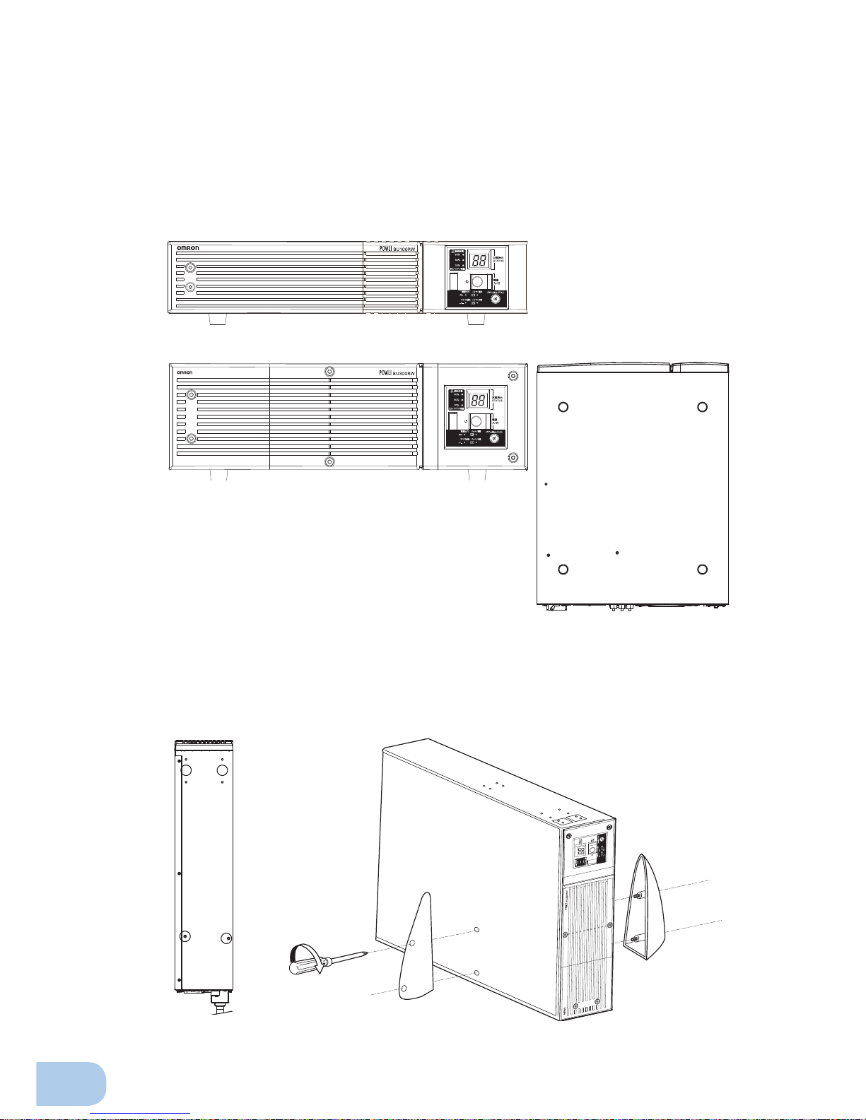
2-2-2. Stationary installation
Perform installation only as shown in the diagrams below.
●
Horizontal installation
Attach the included rubber feet for horizontal installation (14.5 mm depth) to the round stickers
on the unit (4 locations) and position the unit horizontally.
For stationary horizontal installation, make sure that this product does not slide or fall.
BU200RW/BU300RW
●
Upright installation
(1) Upright installation
Use the stand included with the product.
Attach the included rubber feet for upright installation (1.7 mm depth) to the bottom of the unit (4
locations illustrated below) and to the bottom of the stand (1 for each).
BU200RW/BU300RW
BU75RW/BU100RW
Page 27
BU75RW/BU100RW/BU200RW/BU300RW
2
15
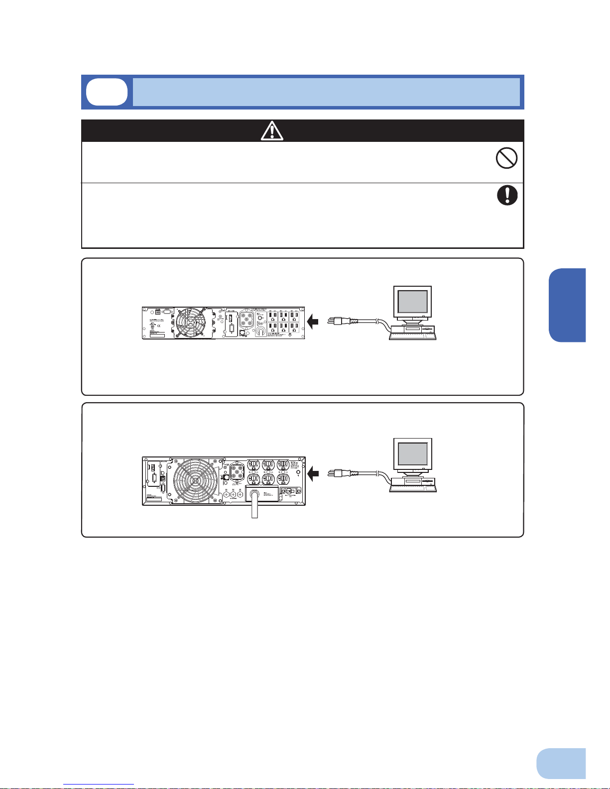
Computer
BU300RW/BU300RW
To power supply
output receptacle
2-3
Connecting the equipment
●
Group control of power supply output
This function can be used with the UPS monitoring software included with the UPS.
The output receptacles of the UPS unit are separated into 3 groups: A, B, and C.
• The output start times for power supply output group B and C are independent of power supply
output group A, so they can be delayed or set to precede the output stop time.
• The output start/stop time control funtion is available when using the included “PowerAct Pro”
UPS monitoring software, “UPS Power Manager” or “SNMP/Web card”.
•
Output ON/OFF can be controlled with the included UPS monitoring software while the UPS unit is
operating.
• The delay settings and ON/OFF control described here can be performed independently for
power supply output group B and power supply output group C.
This function can be used to set the startup order of servers, peripheral devices, etc.
The output receptacles can also be forcibly turned ON/OFF remotely.
Caution
Do not connect devices with rated voltage of 100 to 120 VAC or higher.
●
The rated output voltage of this device is 100 to 120 VAC.
●
Overcurrent may damage the connected devices.
Before connecting the BU200RW and BU300RW to commercial power,
make sure the input terminal block cover is attached. Do not use the unit
without the cover attached.
●
Voltage is applied to the input terminal block when the unit is connected to the commercial
power source, which can result in electric shock.
Computer
To power supply
output receptacle
BU75RW/BU100RW
Page 28
2.Installation and connection
16
2-3-1. Connecting a device to the power supply output (BU75RW/BU100RW)
(1) Connect devices (computer, server, peripherals, etc.) that require backup to the power supply out-
put receptacle on the back of the unit.
Make sure that the total capacity of devices connected to the output receptacle
does not exceed the output capacity rating of the BU75RW/BU100RW. If the overload indicator (
) appears, reduce the number of connected devices.
BU100RW (rated output capacity: 1kVA/800W)
BU75RW (rated output capacity: 750VA/600W)
Power supply output group Output receptacle
Group A NEMA5-15R x 2 (rated value: 10A)
Group B NEMA5-15R x 2 (rated value: 10A)
Group C NEMA5-15R x 2 (rated value: 10A)
Power supply output group Output receptacle
Group A NEMA5-15R x 2 (rated value: 7.5A)
Group B NEMA5-15R x 2 (rated value: 7.5A)
Group C NEMA5-15R x 2 (rated value: 7.5A)
Group control of power supply output See Page 15
See also
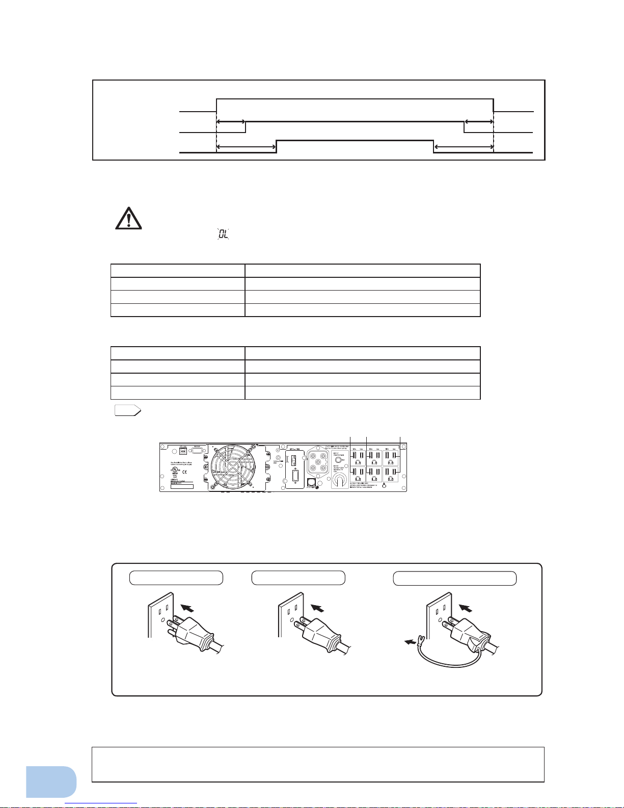
Group A Group B Group C
BU75RW/BU100RW
Power supply output group A
Output ON
Time setting
Time setting
Time setting
Time setting
Output OFF
Power supply output group B
Power supply output group C
• When using a 2-pin input plug, you may directly connect to a Power Supply Output Receptacle
of the UPS. Note 1) When using a 2-pin input plug with a grounding wire, connect the grounding wire to earth in building.
• When you want to use an AC adaptor, connect it to a Power Supply Output Receptacle of the
UPS with space enough for the connection.
Connect it directly. Connect it directly.
(Note 1) This connection is prohibited to use the UPS as device complying with UL Standards or
CE Marking.
Connect the plug directly.
Plug of connected
device
Plug of connected
device
Plug of connected
device
Connect the grounding wire to
earth in building.
Connect the grounding wire of connect
devices to earth of the UPS. (Note 1)
(2) When using the included UPS monitoring software and the Windows standard UPS
service, use a connection cable to connect the unit to the PC.
See also "7. Using the UPS monitoring software and Contact Signal" on page 58.
* If you do not use the UPS monitoring software and Contact Signal, this step is not required.
Page 29
BU75RW/BU100RW/BU200RW/BU300RW
2
17
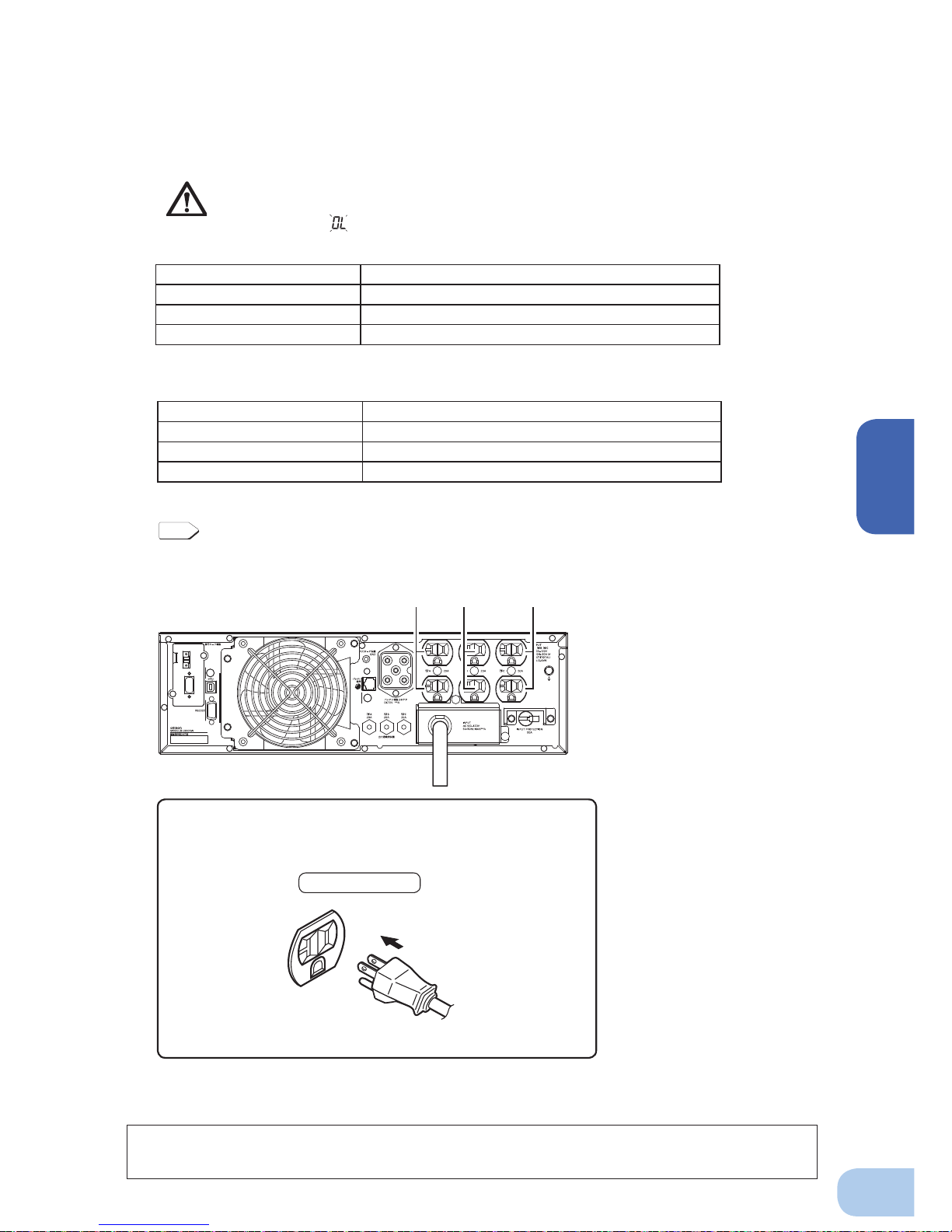
2-3-2. Connecting a device to the power supply output (BU200RW/BU300RW)
(1) Connect devices (computer, server, peripherals, etc.) that require backup to the power supply out-
put receptacle on the back of the unit.
Make sure that the total capacity of the devices connected to the output receptacle
does not exceed the output rated capacity of the BU200RW/BU300RW. If the overload indication (
) is displayed, reduce the number of connected devices.
Group A Group B Group C
Group control of power supply output See Page 15
See also
• Procedure for connection
to power supply output receptacle
Connect it directly.
Plug of connected device
“Power supply output” group Output receptacle
Group A NEMA5-20R: 2 (Rated capacity: 20A)
Group B NEMA5-20R: 2 (Rated capacity: 20A)
Group C NEMA5-20R: 2 (Rated capacity: 20A)
“Power supply output” group Output receptacle
Group A NEMA5-20R: 2 (Rated capacity: 20A)
Group B NEMA5-20R: 2 (Rated capacity: 20A)
Group C NEMA5-20R: 2 (Rated capacity: 20A)
BU200RW (Rated output capacity: 2kVA/1600W)
BU300RW (Rated output capacity: 3kVA/2400W)
BU200RW /BU300RW
(2) When using the included UPS monitoring software and the Windows standard UPS
service, use a connection cable to connect the unit to the PC.
See also "7. Using the UPS monitoring software and Contact Signal" on page 58.
* If you do not use the UPS monitoring software and Contact Signal, this step is not required.
Page 30
2.Installation and connection
18
2-4
Connecting the AC input
When installation and connection are complete, connect the unit’s AC input to a commercial
power source.
Make sure to connect the AC input plug of the unit into a wall outlet
(commercial power) with rated input voltage (100V to 120V AC).
●
Connecting to a wall outlet (commercial power) of a different rated voltage may result in fi re.
●
The unit may fail.
Caution
●
The BU75RW/BU100RW AC input plug cannot be changed.
AC input plug selection: Use the factory settings for setting switches 7 and 8 (both OFF).
●
The AC input connection method can be changed according to the operating environment.
●
The table below shows the status at shipment, how to change the connection, and the allowable
connection capacity.
Change the way to connect to commercial power according to the connection capacity you use.
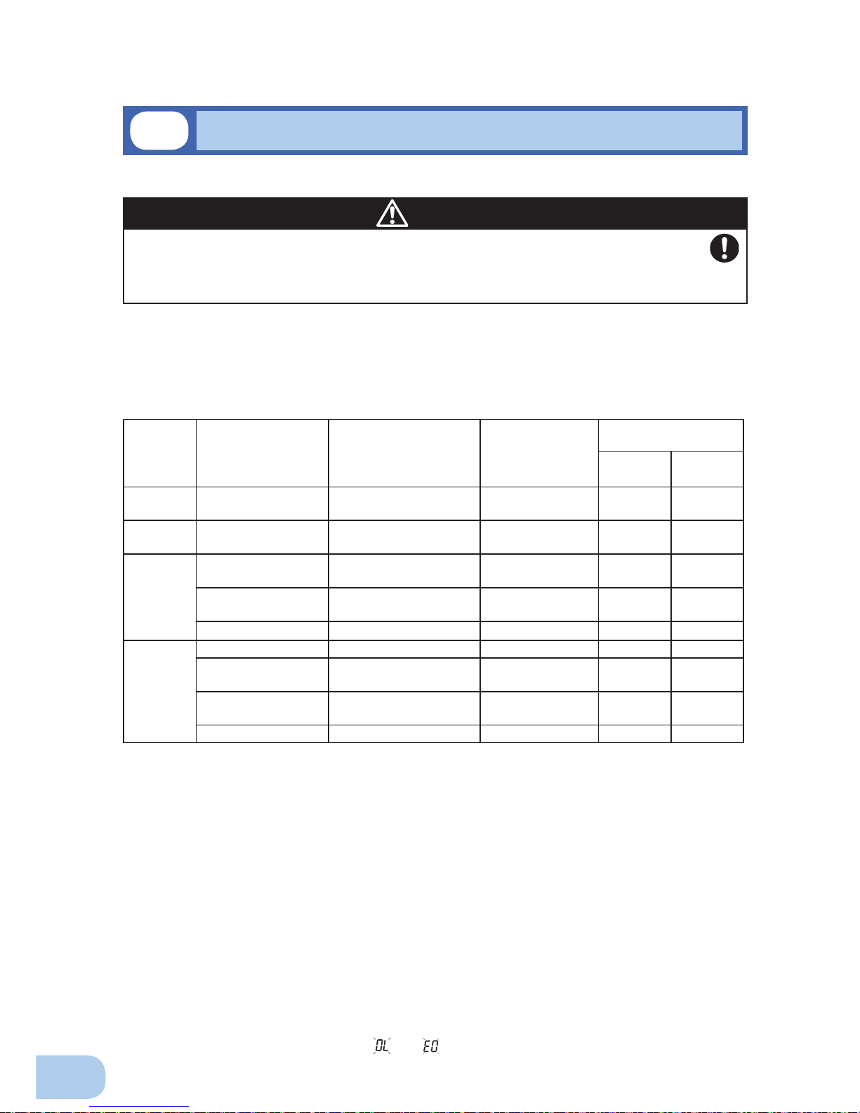
2-4-1. Connecting the AC input plug
BU75RW/BU100RW connection procedure
●
Use the 15A plug included with the product at shipment.
Provide a wall outlet (commercial power) suitable for the shape of the 15A plug (NEMA 5-15R).
●
It is possible to connect to a 2-pin outlet using the included 3P-2P adapter.
BU200RW connection procedure
●
When using the 15A plug (connected when shipped)
●
Provide a wall outlet (commercial power) suitable for the shape of the 15A plug (NEMA 5-15R).
●
The BU200RW comes equipped with a 15A input plug (NEMA 5-15P) at shipment.
If this plug is used, make sure that the capacity of the connected devices stays below the maximum
capacities shown in the table above.
After connecting to commercial power, turn ON the INPUT PROTECTION switch (input overcurrent
protection switch) on the back of the unit.
●
When the overload display appears (“ “ or “ “ is displayed on the status indicator), you cannot
continue using the unit with the 15A input plug.
Model
Input power capacity
(Plug capacity)
Recommended AC input
plug that complies with
unit’s UL standard
Maximum output
capacity
(Allowable connec-
tion capacity)
AC input plug selection
setting switch
Setting
switch 7
Setting
switch 8
BU75RW
15A(attached when
shipped)
NEMA 5-15P 750VA/600W OFF OFF
BU100RW
15A(attached when
shipped)
NEMA 5-15P 1000VA/800W OFF OFF
BU200RW
15A(attached when
shipped)
NEMA 5-15P 1100VA/880W OFF OFF
20A NEMA 5-20P
NEMA L5-20P
1600VA/1280W ON OFF
30A
NEMA L5-30P 2000VA/1600W OFF ON
BU300RW
15A NEMA 5-15P 1100VA/880W OFF OFF
20A NEMA 5-20P
NEMA L5-20P
1600VA/1280W ON OFF
30(attached when
shipped)
NEMA L5-30P 2400VA/1920W OFF ON
35A or more Switchboard connection 3000VA/2400W ON ON
* The bold font indicates factory settings.
Page 31

BU75RW/BU100RW/BU200RW/BU300RW
2
19
Caution
BU300RW connection procedure
●
When using the 30A plug (connected when shipped)
Provide a wall outlet (commercial power) compatible with the shape of the 30A plug (NEMA L5-30P).
●
The BU300RW comes equipped with a 30A input plug (NEMA L5-30P) at shipment.
If this plug is used, make sure that the capacity of the connected devices stays below the maximum
capacities shown in the table above.
●
After connecting to commercial power, turn ON the INPUT PROTECTION switch (input overcurrent
protection switch) on the back of the unit.
●
When the overload display appears (“ “ or “ “ is displayed on the status indicator), you must connect to a power switchboard or switch to a 30A plug. Follow the directions provided in the “Changing
the AC input cable” section below.
When using the 30A plug (NEMAL5-30P) with the BU300RW, the
maximum capacity connectable to the output is approximately
2400VA/1920W.
●
When the power consumption exceeds this capacity, the input voltage becomes larger than
30A, which may lead to overheating or fi re.
●
When the overload display appears (“ “ or “ “ is displayed on the status indicator), you
must change the AC input cable and connect to a commercial power line with a capacity of
35A or more. Follow the directions provided in the “Changing the AC input cable” section below.
Caution
When using the 15A plug (NEMA 5-15P) with the BU200RW, the
maximum capacity connectable to the output is approximately
1100VA/880W.
●
When the power consumption exceeds this capacity, the input voltage becomes larger than
15A, which may lead to overheating or fi re.
●
When the overload display appears (“ “ or “ “ is displayed on the status indicator), you
must switch to a 30A plug. Follow the directions provided in the “Changing the AC input cable”
section below.
<BU75RW/BU100RW>
P C
3P receptacle
2P receptacle
Connect the grounding wire to earth in building
Page 32

2.Installation and connection
20
<BU200RW/BU300RW>
Input plug (L5-30P)
(Front view)
E
N
L
When one wire is used to ground the AC input power
supply, make sure to use this unit's N terminal (phase)
side as the ground.
●
A misconnection may result in malfunction.
Caution
3P receptacle
3P receptacle
3P receptacle
100 VAC
BU200RWBU300RW
Connect the grounding wire
to earth in building
2-4-2. Changing the BU200RW/BU300RW AC input plug
Caution
Caution
Make sure to change the AC input plug selection setting switches ,
(
See also
38 Page) according to the input power capacity.
●
If the proper settings are not made, the warning will not be issued when there is
excessive input current.
Overcurrent may result in smoke or fi re.
Caution
When connecting the AC input directly from a power switchboard to the
BU200RW/BU300RW, make sure that the wiring work is performed by a
qualifi ed electrical engineer (with Type II certifi cation or higher).
●
To use the BU200RW with up to 2000VA/1600W, a wiring capacity of 24A or more is
required.
●
To use the BU300RW with up to 3000VA/2400W, a wiring capacity of 35A or more is
required.
When changing the input cable for the BU200RW and BU300RW, make
sure to perform the connection as specifi ed.
Make sure to properly match the AC input terminal with the appropriate
wire color.
Do not connect the unit’s AC input terminal while it is connected to
commercial power.
●
Failure to do so may result in electric shock or ground fault.
BU300RW
Page 33

BU75RW/BU100RW/BU200RW/BU300RW
2
21
(1) Remove the terminal-cover at AC input. (Two screws)
Use the new AC input
terminal-cover
attached to the new cable.
(2) Remove screws at terminals (L, N, G) connecting the cable to the terminals and remove the old
AC input cable.
(3) Run the newly connected cable through the included AC input terminal cover.
(4) Connect the new AC input cable to AC input terminals by screws.
Be careful to polarities of L, N, G terminals and connect correctly.
unscrew these
Terminal-cover
(5) Fix the AC input terminal-cover to the console by screws.
Connect to AC input terminals by screws.
Replacing the BU200RW/BU300RW AC input cable
●
The unit was charged before shipment, but it may have self-discharged during shipment,
resulting in a reduced backup time.
We recommend charging the unit before use.
When the AC input plug is connected to commercial power (BU75RW/BU100RW), or
when it is connected to commercial power and the INPUT PROTECTION switch (input
overcurrent protection switch) on the back of the unit is turned ON (BU200RW/BU300RW),
the battery automatically starts charging, taking up to 8 hours to complete (24 hours when
an additional battery unit is connected).
●
You can perform "2-5 Checking the operation" on page 22 also before charging the battery.
Screw
GNL
AC100-120V
●
Securely fasten the screws with a tightening torque
of 2.5 Nm (22 Lb-in) or more.
Connectable wire size 5.0 to 8.0mm
2
Amount of stripped wire 5.5mm
Tightening torque 2.5 Nm(22 Lb-in)
Recommended cable size 8mm
2
(AWG 8)
(6) After connecting to commercial power, turn ON the INPUT PROTECTION switch (input overcur-
rent protection switch) on the back of the unit.
Page 34

2.Installation and connection
22
When you fi nish connecting the unit, confi rm that the backup operation works properly.
Check that the Battery Mode is performed normally according to the following procedure.
(In this operation check, the effects of a power failure are reproduced by disconnecting the AC input
plug from the wall outlet (commercial power) or, when using the BU200RW/BU300RW, by turning OFF
the INPUT PROTECTION switch (input overcurrent protection switch).)
(1) Turn ON the unit's power switch.
The beeper sounds and the current settings are displayed on the LED.
After 5 secounds, the self-diagnostic test is performed in Battery Mode for approximately 10
seconds.
When the self-diagnosis test fi nishes normally, the unit’s operation switches to commercial power
and the status indication below is displayed.
(When the battery voltage is low, the self-diagnostic test is not performed and output begins
immediately via commercial power.)
(2) Bring all the connected devices into operation.
(Including devices connected to the AC outlet of your PC.)
The unit was charged before shipment, but it may have
self-discharged during shipment, resulting in a reduced
backup time. We recommend charging the unit before use.
.
(3) Under this condition, check the the unit's LED display and beep sound.
Are they in the same status as shown below?
Status indicator
Beep None
Power supply output receptacles Outputs power (connected devices are powered)
If the same as the one shown above:
→ The operation is normal. Proceed to (4).
If not the same as the one shown above:
→ The operation is abnormal. One of the cases described in
"4. Display and beeps when there is an equipment failure"
of "3-3 Interpreting a beep and displays" on page 31 must
apply.
Take necessary measures and then proceed to (4).
(4) Disconnect the unit’s AC input plug from the wall outlet (commercial power) or, when us-
ing the BU200RW/BU300RW, turn OFF the INPUT PROTECTION switch (input o vercurrent
protection switch) on the back of the unit.
The unit enters Battery Mode.
2-5
Checking the operation
Status indicator Description
Power switch “ON”
Operating normally
ON DIP
1 2
5 6 7
8
3 4
ON←
ON OFF
ON,OFF,orblinking
dependingonstatus
Page 35

BU75RW/BU100RW/BU200RW/BU300RW
2
23
(5) In Battery Mode, check the unit's LED display and beep sound.
Does the status indicator appear as one of those shown below?
If not the same as one of those shown above:
→ Operation is abnormal. Check the status of lamps and beep
and turn OFF the Power Switch.
• If the display is one of those shown in “4. Displays and
beeps when there is an equipment failure” in “3-3 Interpreting beeps and displays” on page 31, take the necessary measures and then go back to (1) on page 22.
• If no Battery Mode is performed and the UPS and the
devices connected to the UPS stop, this may be attributed to an insuffi cient battery charge.
For the BU75RW/BU100RW: After connecting the AC
input plug to a wall outlet (commercial power) and waiting 8 hours for the battery to charge (24 hours when an
additional battery unit is connected), go back to step (4)
on page 22.
For the BU200RW/BU300RW: After connecting the AC
input plug to a wall outlet (commercial power), turning
ON the INPUT PROTECTION switch (input overcurrent
protection switch) on the back of the unit, and waiting at
least 8 hours for the battery to charge (24 hours when an
additional battery unit is connected), go back to item 4
on page 22.
• If the problem persists after checking the 2 points above,
contact us; ____
See also
Setting switch can be used to turn the beeper ON/OFF. → Page 35
(6) Reconnect the AC input plug to the commercial power source.
Turn ON the INPUT PROTECTION switch (input overcurrent protection switch)
on the back of the BU200RW/BU300RW.
The status indicator returns to its normal state and the beeping sound stops.
(The status is as shown below.)
Checking the operation is now complete.
Installation and connection is now complete.
( indicates blinking)
Status indicator Beep Output Charging Description
Intermittent
4-second
intervals
ON
OFF
Discharging
Backup is operating due to power failure or AC input er-
ror. Output will stop if Battery Mode continues.
Intermittent
1-second
intervals
ON
OFF
Discharging
(Same as above.)
Battery level is low, so output will stop soon.
None OFF
OFF
Discharging
Battery is dead, so output stopped. (This is displayed
only for a few seconds.)
Status indicator Description
Power switch “ON”
Operating normally
Page 36

2.Installation and connection
24
For the BU75RW/BU100RW: The battery automatically starts charging when the AC input plug
is connected to a wall outlet (commercial power).
(This occurs regardless of whether the power switch is ON or OFF.)
The charging takes 8 hours to complete (24 hours when additional battery unit is connected).
For the BU200RW/BU300RW: The battery automatically starts charging when the AC input
plug is connected and the INPUT PROTECTION switch (input overcurrent protection switch) is
turned ON.
(This occurs regardless of whether the power switch is ON or OFF.)
The charging takes up to 8 hours to complete (24 hours when additional battery unit is connected).
●
The unit was charged before shipment, but it may have self-discharged during shipment, resulting
in a reduced backup time. We recommend charging the unit before use.
●
If you do not perform the initial backup time measurement described below in “2-7 Measuring the
initial value of backup time”, proceed to “3. Operation. → Page 25”
●
When you measure the backup time initial value of the unit in your environment, this value can
be used as a guide when checking the battery and deciding the UPS monitoring software setting
values.
See also
"5. Measuring the backup time" → Page 43
The battery is discharged completely when the backup time is measured, so you need to recharge it
before using the UPS.
●
You can use connected devices while recharging the battery, but the backup time when a power fail-
ure occurs is shorter until the battery is fully charged.
(If a power failure occurs immediately after the start of charging, backup stops immediately.)
See also
Charge the battery as described in "2-6 Charging the battery."
Preparation for starting operation is now complete.
2-6
Charging the battery
2-8
Recharging the battery
2-7
Measuring the initial value of backup time
Page 37

3
25
3-1
Precautions and notes for operation
Operation
33
Do not allow the unit to come in contact with water.
●
Doing so may cause an electric shock or a fi re.
●
If the unit becomes wet, immediately stop using it, disconnect the AC input cable from the wall
outlet (commercial power) or, when using the BU200RW/BU300RW, turn OFF the INPUT PROTECTION switch (input overcurrent protection switch) on the back of the unit, and have it inspected and repaired.
For repair, contact us:____________
When the battery is dead, replace it immediately or stop using the unit.
●
Continuing the use of it may cause a fi re.
Using a dry cloth, periodically wipe the dust from the AC input plug and
power supply output receptacles.
●
Accumulated dust may cause a fi re.
Do not use the unit in a closed place and do not cover the unit.
●
Doing so may cause abnormal heating or a fi re.
If you notice an abnormal sound or smell, smoke, or leaking fluid,
immediately turn OFF the unit’s power switch and stop the supply of
commercial power.
(
For the BU75RW/BU100RW, disconnect the AC input plug from the wall outlet.
For the BU200RW/BU300RW, disconnect the AC input plug from the wall
outlet (commercial power) or turn OFF the INPUT PROTECTION switch
(input overcurrent protection switch) on the back of the unit.)
●
Using the unit under such conditions may cause a fi re.
●
If you notice such a condition, stop using the unit and contact us at _____ for inspection and repairs.
●
Position the BU200RW/BU300RW in such a way that you can immediately disconnect the AC
input plug from the wall outlet (commercial power) or turn OFF the INPUT PROTECTION switch
(input overcurrent protection switch) on the back of the unit in the event a problem occurs.
If fl uid leaks from the unit, do not touch the fl uid.
●
Doing so may cause blindness or burns.
●
If the fl uid contacts your eyes or skin, wash it out with lots of clean water and consult your doctor.
Do not place objects heavier than 25kg on the unit, and do not drop heavy
objects onto the unit.
●
Doing so may cause distortion/damage to the case or a failure of the internal circuit, which may
cause a fi re.
BU300RW is equipped with a bypath circuit which is able to supply
electric power to connected devices even when the inner control circuit is
broken down by defects or malfunctions
●
Output is continuing even when all indicators of the front panel are off.
●
If you want to stop the output, either stop the source of commercial power, disconnect the AC
input plug from the wall outlet (commercial power) or, if using the BU200RW/BU300RW, turn OFF
the input overcurrent protection switch (INPUT PROTECTION switch) on the back of the unit.
Ambient temperature Expected life
20°C 4 to 5 years
30°C 2 to 2.5 years
* The values in the table are the expected life under standard
use conditions and are not guaranteed.
Caution
(for use)
Take notice of following items during operation.
Page 38

3.Operation
26
Explanation
Usual operation
●
You may either leave the power switch of the unit ON (operation status) or turn it OFF each time when
stopping the connected system. Choose whichever operation method is more convenient. We recommend turning OFF the power switch when you do not use connected devices for a long time.
●
BU75RW/BU100RW: The battery can be charged once the AC input plug of the unit is connected to a wall
outlet (commercial power).
BU200RW/BU300RW: The battery can be charged once the AC input plug is connected to a wall outlet
(commercial power) and the INPUT PROTECTION switch (input overcurrent protection switch) on the
back of the unit is turned ON.
Quitting Battery Mode
●
If a power failure lasts for an extended period of time, the battery discharges and power output from the
unit stops. Shut down your computer after performing appropriate procedures (for example, saving data)
while the unit is still supplying power.
Rebooting
●
If the battery discharges completely during a power failure, the unit stops. After recovery from the power
failure, the unit automatically restarts and supplies power. If you do not want to restart the connected devices, turn OFF the power switch of either the unit or the connected devices.
See also
Setting switch can be used to select whether or not auto restart is performed. See Page 35
Scheduled operation using the UPS monitoring software
●
When performing scheduled operation in which the UPS is stopped and a device such as a breaker is
used to stop the UPS at the same time that commercial power stops, specify a period of no more than 3
months for the start of the next operation. If you specify a period longer than 3 months, the internal timer
is reset and the scheduled operation does not start.
Note that this period reduces to less than half when the battery is at the end of its life.
If a period of 3 months is exceeded, you start operation by supplying commercial power and pressing the
Start Switch. However, if the battery is deteriorated, you may not be able to start operation. In this case,
replace the battery according to the instructions in “6-2 Replacing the battery” on page 46.
Notes
Before stopping the commercial power to the unit, turn OFF the power switch of the unit.
●
The unit enters Battery Mode when commercial power is stopped. If you frequently use the unit in Battery
Mode, the battery life may be signifi cantly shortened.
Take measures for handling unforeseen accidents, such as data backup
and system redundancy.
●
The output may stop when there is a circuit failure in the UPS.
Page 39

BU75RW/BU100RW/BU200RW/BU300RW
3
27
3-2
Start and stop procedures and basic operation
See also
Cold start ON/OFF setting → Page 39
• During operation, the battery is charged automatically.
●
When the power switch is OFF and the AC input plug is connected to a
commercial power supply:
(Turn ON the INPUT PROTECTION switch (input overcurrent protection switch) on the back of the
BU200RW/BU300RW.)
• The details of the most recent error are displayed. (item 4 on page 31)
• The status indicator displays "
".
• Power output is stopped.
• The battery automatically starts recharging.
●
Start procedure
Operation
Turn on the power switch of the UPS.
• Output begins in Bypass Mode about 5 seconds after the switch is activated. (Status indicator “
“)
However, “
“ is displayed at cold start, and output begins in Battery Mode.
• The status indicator displays “
“, and the self-diagnostic test is performed in Battery Mode
for about 10 seconds. (If the battery voltage is low, the self-diagnostic test is not performed. It is
automatically executed after the battery is charged.)
1. When the self-diagnostic test fi nishes successfully, switching to AC output from commercial
power is performed and normal operation starts.
2. Self-diagnostic test is not performed at cold start.
• When the self-diagnosis test fi nishes normally, the unit switches to AC output via commercial
power and enters the normal operating state through inverter operation.
• When the self-diagnostic test is not performed, AC output begins immediately via commercial
power.
ON
OFF
ON
OFF
ON
OFF
ON
OFF
Commercial Power
Battery
Bypass
Inverter
Commercial Power
Battery
D-1
<Note>
D-1 : The most recently displayed error code (refer to item 4 on page 31)
(If no errors have occurred, " " is displayed.)
Commercial
operation
AC input
7 seg.
Power supply SW
Power supply
output lamp
Bypass operation
lamp
Operating mode
Operating mode
Output
Startup
preparation
about
5 sec.
about
10 sec.
about
2 to 3 sec.
Bypass
mode
Self-diagnostic
test
1 sec.
Status indicator
Beep None
Power supply output receptacles Outputs power (connected devices are powered)
Page 40

3.Operation
28
●
Operation after a power failure
• If a power failure or abnormal input power supply occurs, the UPS automatically switches to
Battery Mode, continuing power output from the Power Supply Output Receptacles supplied
from the battery.
• The status is displayed and the beeper sounds intermittently to alert the user.
See also
Setting switch can be used to turn the beeper ON/OFF. → Page 35
( indicates blinking)
Status
indicator
Battery
replacement
Beep Output Charging Description Solution
Intermittent
4-second
intervals
ON
OFF
Discharging
In Battery Mode due to power
failure or AC power error.
Perform shutdown
operations for the
connected devices
and stop them.
Intermittent
1-second
intervals
ON
OFF
Discharging
(Same as above.)
Battery level is low, so output
will stop soon.
(Same as above.)
None OFF
OFF
Discharging
Battery is dead, so output
stopped.
Charge the battery.
Page 41

BU75RW/BU100RW/BU200RW/BU300RW
3
29
●
Connection capacity/battery level meter
In Commercial Power Mode (normal operation), the power consumption of devices connected to the
capacity/battery level meter is displayed as a percentage.
BU75RW: Displayed in 3 levels, with 100% indicating 750VA/600W.
BU100RW: Displayed in 3 levels, with 100% indicating 1000VA/800W.
BU200RW: Displayed in 3 levels, with 100% indicating 2000VA/1600W (when 30A plug or power switchboard
is connected), 1600VA/1280W (when 20A plug is connected), or 1100VA/880W (when 15A plug is
connected).
BU300RW: Displayed in 3 levels, with 100% indicating 3000VA/2400W (when power switchboard is
connected), 2400VA/1920W (when 30A plug is connected), 1600VA/1280W (when 20A plug is
connected), or 1100VA/880W (when 15A plug is connected).
When the connection capacity is 30% or less, the level meter turns OFF.
In Battery Mode, the battery level is displayed as a percentage.
Connection
capacity
Battery level
●
Operation during recovery from a power failure
• The unit automatically resumes output via commercial power if it recovers from a pow er
failure/input power supply error while it is providing power supply output. The spent battery
starts charging.
• If a power failure or abnormal power input is resolved after the battery is discharged completely
and power output is stopped, the UPS restarts automatically and resumes power output. The
expended battery begins to charge.
See also
Setting switch can be used to select whether or not auto restart is performed. → Page
35
●
Stop procedure
Operation
Turn ON the power switch of the UPS.
• The power output from the UPS stops.
• Even if you turn off the power switch, if AC is supplied from commercial power, the battery is
automatically charged.
* In Commercial Power Mode (normal operation), the battery level is displayed when the beeper
stop/test switch is pressed.
(Please note that if the button is pressed and held for 5 seconds or more, the beeper begins to
sound and the self-diagnostic test starts.)
Status
indicator
Battery
replacement
Beep Output Charging Description
None OFF ON
There is AC input
Power switch "OFF"
In Commercial Power Mode
Connection capacity
Indicator is ON
Indicator is ON In Battery Mode Battery level
Indicator blinks
90% lamp
60% lamp
30% lamp
All OFF
90% or more
60% or more
30% or more
30% or less
60% or more
30 to 60%
0 to 30%
—
Page 42

3.Operation
30
1. Displays and beeps in normal operation
(1) When power switch is OFF
No.
Status
indicator
Power supply
output
lamp
Beep Charging Description Solution
1
None
OFF
No AC input.
_ _
_ _
Operation stopped.
2
None
ON
There is AC input.
Power switch is OFF.
ON
Power switch is ON.
Operating normally.
Bypass
operation
lamp
Battery
replacement
lamp
( indicates blinking)
( indicates the display is ON)
( indicates the display is OFF)
(2) When power switch is ON
3
None
_ _
4
None
ON
Battery charge is low, so
the unit is waiting to start
up.
Continue charging the
battery. Output will start
when the battery is charged.
2. Displays and beeps while testing
5
None
6
None
OFF
Discharging
Discharging
Self-diagnostic test in progress.
OFF
Auto battery test in progress.
_ _
_ _
3. Displays and beeps during power failure or AC input error
(1) When power switch is ON
(2) When power switch is OFF
7
8
OFF
Discharging
OFF
Discharging
Discharging
9
None
OFF
In Battery Mode due to power
failure or AC input error.
Output will stop if Battery
Mode continues.
(Same as above.)
Battery level is low, so output
will soon stop.
Battery is dead,
so output stopped.
(This is displayed only for
a few seconds.)
Use within the AC input voltage/
frequency range described
in the specifications.
See Page 83
Intermittent
4-second
intervals
Intermittent
1-second
intervals
(Same as above.)
Perform shutdown operations
for the connected devices
and stop them.
Charge the battery.
10
11
12
13
None (ON)
None (ON)
None (ON)
None (ON)
14
None (ON)
15
None (ON)
16
None (ON)
17
None (ON)
AC input voltage is too high.
AC input voltage is too low.
AC input voltage and AC input
frequency are both too low.
AC input frequency is too low.
AC input voltage and AC input
frequency are too high.
AC input voltage is too low
and AC input frequency is too
high.
AC input voltage is too high
and AC input frequency is too
low.
AC input frequency is too
high.
3-3
Interpreting beeps and displays
Page 43

BU75RW/BU100RW/BU200RW/BU300RW
3
31
See also
“6-3 Replacing the fan”
(Note 2)
Switched to bypass operation
due to problem with external
cooling fan (Note 1).
Failure occurred. When the beep
stop switch is pressed, the details
of the error are displayed
(No. 25 to 30).
Turn OFF this unit and all connected
devices. Then, turn the power switch
back ON for this unit only. If the display
does not change, there is a problem
with this unit. Contact the shop of
purchase or our Electronic Systems &
Equipments customer support center
at: _____
(Same as above.)
Moved to bypass operation due
to the direct current bus voltage
error (Note 1).
4. Displays and beeps when there is an equipment failure
(1) When power switch is ON
ON
or
discharging
ON
or
discharging
ON
or
discharging
18
19
20
ON
or
discharging
21
22
OFF
(Note 3)
_ _
(Note 3)
_ _
_ _
_ _
23
25
_ _
26
_ _
29
_ _
30
28
OFF
OFF
27
24
( indicates blinking)
( indicates the display is ON)
( indicates the display is OFF)
Stopped charging due to
abnormal drop in battery
charge voltage. When the
battery discharges, bypass
output is performed.
(The display disappears
completely.)
No.
Status
indicator
Power supply
output
lamp
Beep Charging Description Solution
Bypass
operation
lamp
Battery
replacement
lamp
Switched to bypass operation
due to abnormal rise in output
voltage. (Note 1).
Displays the details of the error that
occurred only while pressing the beep
stop switch while in state No. 24.
Displays the details of the error that
occurred only while pressing the beep
stop switch while in state No. 23.
Displays the details of the error that
occurred only while pressing the beep
stop switch while in state No. 24.
Switched to bypass operation
due to abnormal drop in output
voltage. (Note 1).
(Same as above.)
(Same as above.)
Moved to bypass operation due
to problem with the internal
temperature (Note 1).
Intermittent
0.5-second
intervals
Intermittent
0.5-second
intervals
Continuous
Continuous
Continuous
Continuous
There are too many connected
devices and the rated capacity is
exceeded. If this state continues
for as long as or longer than the
times described below,
commercial power continues
to be supplied through bypass
operation (Note 1).
%
When connection capacity is
at 110% or higher: Bypass
operation begins after 10 seconds
%
When connection capacity is
at 130% or higher: Output stops
after 1 minute (Go to No.20)
%
When connection capacity is
at 150% or higher: Output stops
after 10 seconds (Go to No.20)
Reduce the number of connected
devices until the display appears
as in status No. 3.
Turn OFF the power switches of
all devices connected to the unit,
reduce the number of connected
devices, and turn the power switch
back ON again.
Output stopped due to exceeded
connection capacity.
Continuous
Continuous
Continuous
Continuous
Continuous
Continuous
Continuous
Stopped charging due to
abnormal rise in battery
charge voltage. When the
battery discharges, bypass
output is performed.
(The display disappears
completely.)
Check that the connection
capacity has not exceeded
the rated capacity.
Replace the cooling fan if it does
not function properly.
Note 1: In bypass operation, commercial power is output directly. Output stops when a power failure (AC input OFF)
occurs in bypass operation.
Note 2: Fan replacement performed by the user does not comply with UL, CE standards.
Note 3: The displays and operations vary according to the status.
Blinking
Blinking
Blinking
Check that the AC input of connected
devices is not short-circuited, or that
the connection capacity does not
exceed the rated capacity.
Page 44

3.Operation
32
OFF
OFF
OFF
There is a problem with the unit.
Contact the shop of purchase or the
OMRON Electronic Systems &
Equipments Customer Support Center
at: __________.
31
32
Failure occurred. When the beep
stop switch is pressed, the details
of the error are displayed.
33
(Same as above.)
Stopped charging due to
abnormal drop in battery charge
voltage.
Displays the details of the error that
occurred only while pressing the beep
stop switch while in state No. 31.
Continuous
Continuous
Continuous
No.
Status
indicator
Power supply
output
lamp
Beep Charging Description Solution
Bypass
operation
lamp
Battery
replacement
lamp
4. Displays and beeps when there is an equipment failure
(2) When power switch is OFF
( indicates blinking)
( indicates the display is ON)
( indicates the display is OFF)
Stopped charging due to
abnormal rise in battery charge
voltage.
Seealso
Replacingthebattery
46Page
5. Display and beep for battery replacement
34
The battery test detected
a weak battery
(warning only, output continues).
Replace the battery.
You can replace the weak battery
with a separately purchased
replacement battery as needed.
Intermittent
2-second
intervals
ON
Page 45

4
33
When the beep is sounding, you can suspend it by pressing and holding the beep stop/test switch for 0.5
seconds or longer.
This test performs a failure diagnosis on the unit and performs a simple test to check for battery deterioration.
Use the procedure below to check whether a circuit failure has occurred inside the unit and whether
battery replacement is required.
If the battery is not fully charged, the self-diagnostic test is not executed immediately.
After charging is complete, it is automatically executed.
(1) Connect your computer and other devices to the UPS and then turn ON the power switch of the
UPS.
(2) The Battery Mode starts for testing purpose automatically (Status indicator “
” ). (No beep
sounds.) After about 10 seconds, when the test is complete the normal operation automatically
starts.
(3) If the status indicator/battery replacement lamp blinks and the beeper sounds:
See also
"3-3 Interpreting beeps and displays" → Page 30
Follow the directions for the solutions described in “4. Displays and beeps when there is an equip-
ment failure” and “5. Display and beep for battery replacement”.
* This test can also be run from the included UPS monitoring software.
For more details, refer to the online help for the UPS monitoring software.
This test can also be performed manually.
Press and hold the Beep Stop/Test Switch of the UPS for 5
second or longer.
When the beeper begins to sound intermittently, release the
Switch.
4-1
Suspending a beep
UPS functions
44
4-2
Self-diagnosis test
Page 46

4. UPS functions
34
This test performs a failure diagnosis on the unit and checks for battery deterioration (it tends to detect
battery deterioration earlier than the self-diagnostic test does). This test is performed automatically. (You
do not have to perform any special operations.)
The test is performed once every 4 weeks after the AC input is connected to commercial power and
power distribution begins. The test is not performed if the power switch is OFF or if the battery is not
fully charged.
The test is not performed if the power switch is OFF or if the battery is not fully charged.
(1) When the auto battery test starts, the Battery Mode automatically starts (Status indicator “
” ). (No
beep sounds.) After the auto battery test is complete, the normal operation automatically starts.
(2) If the status indicator/battery replacement lamp blinks and the beeper sounds:
See also
"3-3 Interpreting beeps and displays" → Page 30
Follow the directions for the solutions described in “4. Displays and beeps when there is an equip-
ment failure” and “5. Display and beep for battery replacement”.
ON DIP
1 2
5 6 7
8
3 4
ON←
4-4-1. Changing the setting switches
This test can also be performed manually.
Press and hold the Beep Stop/Test Switch of the UPS for 10 second or longer.
When the beeper changes from intermittent beeps to a sustained beep, release the switch.
• Use a fi ne-pointed tool such as a small screwdriver to maneuver the switch’s lever.
4-3
Description of the auto battery test function
4-4
Changing the setting of the functions
-iÌÌ}ÊÃÜÌVÊvÕVÌÊÃÌÊ
No. Function to set OFF side ON side
Setting for beeper
sound in the event
of power failure, etc.
1
Beeper sounds
Beeper does not
sound
2
3
Auto startup setting
after recovery from
power failure
Auto startup is
performed
Auto startup is
not performed
Setting for whether
or not to perform
battery test
Test is performed
Test is not
performed
4
Auto startup mode
setting
Mode A Mode B
5
BS signal valid
range setting
Always enabled
Enabled only during
Battery Mode
6
7
AC input selection
See page 38.
8
• BS signal: UPS stop signal
See also
" 7-4. Contact signal " →Page 70
The setting switch on the Front of the UPS allows you to select the "disable the auto battery test" setting.
See also
"4-4 Changing the setting of the functions" → Page 34
See “Setting for whether or not to perform battery test.”
After changing the setting switch, turn OFF the UPS power switch, disconnect the AC
input plug or, when using the BU200RW/BU300RW, turn OFF the INPUT PROTECTION
switch (input overcurrent protection switch) on the back of the unit. Then, after
confi rming that the status indicator has turned OFF completely, reconnect the AC
input plug or turn the input overcurrent protection switch back ON, and turn ON the
power switch.
●
The setting switch changes do not become valid until the AC input plug is reinserted.
After changing the setting switch, follow the procedure described below.
Page 47

BU75RW/BU100RW/BU200RW/BU300RW
4
35
●
Setting for beeper sound in the event of power failure, etc. (setting switch )
…
Factory setting: OFF
OFF: The beeper sounds when an alarm is necessary.
ON: The beeper does not sound for backup operation or battery replacement. The beeper
sounds for other errors (connection capacity exceeded, operation error, etc.).
ON DIP
1 2
56783 4
●
Auto startup setting after recovery from power failure (setting switch )
…
Factory setting: OFF
OFF: Automatically starts when power is restored.
After a power failure occurs and the unit shuts down using the shutdown software or contact
signal(BS signal), the unit automatically starts and begins to output when the commercial
power is restored.
ON: Does not automatically start when power is restored.
After the unit is shut down with the UPS monitoring software or contact signal (BS signal), it
does not start up when commercial power is restored. Startup is performed by turning the
power switch OFF once, and then back ON again.
1 2 53 4 86 7
ON DIP
●
Setting for whether or not to perform battery test (setting switch )
…
Factory setting: OFF
OFF: The battery test is automatically executed once every 4 weeks.
ON: Does not perform the auto battery test.
Use this setting to disable Battery Mode for for the regularly performed auto battery test.
1 2 53 4 86 7
ON DIP
Page 48

4. UPS functions
36
(1) When BS signal is used to stop the UPS after a power failure occurs.
AC input
Power output
(Setting switch 4 OFF:
Mode A)
Power output
(Setting switch 4 ON:
Mode B)
ON
OFF
ON
OFF
ON
OFF
ON
OFF
BS signal
*1
●
Auto startup mode setting (setting switch ) … Factory setting: OFF
OFF: (Mode A) After UPS stopped, the UPS is automatically started immediately when “ON” is
detected for the AC input.
ON: (Mode B) After UPS stopped, the UPS is automatically started in the AC input’s “OFF to
ON” timing that is detected.
(Defi nition of AC input OFF: When AC input is OFF for 1 second or more)
* Setting switch 4 is valid when the auto startup after recovery from power failure setting (setting
switch 2) is set to OFF (auto restart is performed).
* This setting mode is valid only after the UPS has been stopped by the contact signal backup
stop signal (BS).
* When a cable is connected to the RS-232C connector and the UPS monitoring software is used,
the unit operates in Mode A regardless of this setting.
1 2 53 4 86 7
ON DIP
Page 49

BU75RW/BU100RW/BU200RW/BU300RW
4
37
(2) When BS signal is used to shut down the UPS when AC input is ON
*1
Starts up when BS signal
turns OFF
Starts up when AC input
turns from OFF to ON
ON
OFF
ON
OFF
ON
OFF
ON
OFF
1 sec
AC input
Power output
(Setting switch 4 OFF:
Mode A)
Power output
(Setting switch 4 ON:
Mode B)
BS signal
* 1: BS signal reception time corresponds to the setting switch 5.
●
BS signal valid range setting (setting switch ) … Factory setting: OFF
OFF: The BS signal is always valid (receivable).
The unit’s “power output” can be stopped by inputting a “ON” backup power supply stop sig-
nal (BS) that continues for 10 seconds or more.
ON: The BS signal is valid (receivable) only when in Battery Mode. (The signal is not received
when in Commercial Power Mode.)
The unit’s “power output” can be stopped by inputting a “ON” backup power supply stop sig-
nal (BS) that continues for 0.01 (10 ms) seconds or more.
Use this setting in commercial operation when you do not want to stop operations when a
backup power supply stop signal (BS) is received.
•Auto startup operation when power is restored
Auto startup when power is restored is associated with setting switch 2.
However, the unit does not start up when the BS signal is ON.
1 2 53 4 86 7
ON DIP
*1*1
*1
AC input
●BS signal valid range setting (setting switch )
BS signal
Power supply output
(Setting switch OFF)
Power supply output
(Setting switch ON)
Note 1: Operation when setting switch 2 is OFF (auto startup is performed). When it is ON (auto startup is not performed) auto startup is not performed.
10 sec
10 sec
0.01 sec
ON
OFF
ON
OFF
ON
OFF
ON
OFF
Commercial Power Mode
Battery Mode
Operationg Mode
Page 50

4. UPS functions
38
●
AC input plug selection (setting switch , )
…
Factory setting: Refer to the table below.
Setting switch Setting switch
BU75RW BU100RW BU200RW BU300RW
OFF OFF
15A
Factory setting
15A
Factory setting
15A
Factory setting
15A
ON OFF - - 20A 20A
OFF ON - -
30A or power
switchboard con-
nection
30A
Factory setting
ON ON - - -
35A or greater power
switchboard connection
BU75RW
Use the factory settings for 7 and 8 (both OFF). The UPS can be connected to a rated output
capacity as high as 750VA/600W (factory settings).
BU100RW
Use the factory settings for 7 and 8 (both OFF). The UPS can be connected to a rated output
capacity as high as 1000VA/800W (factory settings).
BU200RW
OFF, OFF: Use this setting when using the 15A AC plug that is connected at shipment. The
UPS can be connected to a rated output capacity as high as 1100VA/880W (factory settings).
ON, OFF: Use this setting when changing to a 20A AC input plug. The UPS can be con-
nected to a rated output capacity as high as 1600VA/1280W.
OFF, ON: Use this setting when changing to a 30A AC input plug or power switchboard
connection.
The UPS can be connected to a rated output capacity as high as 2000VA/1600W.
BU300RW
OFF, OFF: Use this setting when changing to a 15A AC input plug. The UPS can be
connected to a rated output capacity as high as 1100VA/880W.
ON, OFF: Use this setting when changing to a 20A AC input plug. The UPS can be
connected to a rated output capacity as high as 1600VA/1280W.
OFF, ON: Use this setting when using the 30A AC input plug that is connected at
shipment. The UPS can be connected to a rated output capacity as high as
2400VA/1920W. (Factory settings)
ON, ON: Use this setting when changing to an AC input plug that is connected to a
power switchboard. The UPS can be connected to a rated output capacity as
high as 3000VA/2400W.
1 2 53 4 86 7
ON DIP
Page 51

BU75RW/BU100RW/BU200RW/BU300RW
4
39
"
"
"
"
"
Ê«ÕÌ
-ÊÃ}>
*ÜiÀÊÃÕ««ÞÊ
ÕÌ«ÕÌ
"
*ЬiАКХМ«ХМКГМ«К`i>ЮКМi
/ÃÊÌ}ÊÃÊ£äÊÃÊÀÊ£äÊÃiV°Ê
/}ÊVÀÀië`ÃÊÌÊÌiÊÃiÌÌ}ÃÊ
vÀÊÃÜÌVÊÊ°ÊÊ
3) Power output stop delay time setting
It is possible to set the delay time for stopping the power supply output after the BS signal is
received. (Setting range: 0 to 10 minutes, 6 steps)
<Note>
The remote ON/OFF signal is not related to this setting.
When the remote ON/OFF signal is “High”, the UPS stops the output immediately.
See also
→ Page 37
4-4-2. UPS operation mode settings
1. Settable items and explanations
There are 4 items to select.
1) Cold start ON/OFF setting
2) Output voltage setting
3) Power output stop delay time setting
4) Signal input/output test
The settings available for this operation are shown below.
1) Cold start ON/OFF setting
• Cold start OFF mode
The unit can start up only when there is AC input.
• Cold start ON
It is possible to start up the unit even when there is no AC input plug.
(It is not possible, however, to start up the unit by the remote signals.)
Normal operation occurs when AC input is ON. The output frequency is the same as the fre-
quency the last time there was AC input.
2) Output voltage setting (100V/110V/115V/120V)
Four types of output voltage can be set. (Setting range: 100V/110V/115V/120V)
Output is performed at the set voltage, with no relation to the input voltage.
See also
→ Page 42
Page 52

4. UPS functions
40
Output signal Input signal
Battery Low signal (BL)
(Between pins 1 and 5)
Trouble signal (TR)
(Between pins 2 and 5)
Backup signal (BU)
(Between pins 8 and 5)
Deteriorated battery
signal (WB)
(Between pins 9 and 5)
Backup power supply
stop signal (BS)
(Between pins 3 and 5)
Remote ON/OFF signal
(Between pins 6 and 7)
While the signal is being input, these status
indications blink and the beep sounds.
Beep
Signal input/output test start
ON
OFF
ON
OFF
ON
OFF
ON
OFF
ON
OFF
ON
OFF
ON
OFF
Signal output test
Contact signal is forced to turn ON.
Signal input test
While the signal is being
input, the status indicator
blinks and the beep sounds.
Signal input/output test end
4) Signal input/output test (BL/TR/BU/WB/BS/remote)
●
Four types of output signal can be forcibly turned ON.
●
The ON/OFF state of two types of input signal can be checked with the status indicator
and the beeper.
Page 53

BU75RW/BU100RW/BU200RW/BU300RW
4
41
(1) When the beeper stop switch is briefl y pressed (for less than 1 second), the next item is dis-
played.
(2) The unit enters the “individual item setting mode” when the beeper stop switch is pressed and
held (for more than 1 second).
(3) When the power switch is turned OFF, the setting mode quits and the unit enters power switch
OFF status (status
).
ColdstartON/OFFsetting
Outputvoltagesetting
Powersupplyoutputstopdelaytimesetting
Signalinput/outputtest
The UPS operation mode can be set if the power switch is turned ON while the beeper stop
switch is pressed.
Note: While in setting mode, output from the power supply output is OFF even if the power switch
is ON.
2. Settings
Page 54

4. UPS functions
42
ON Cold start ON mode
C
C *1
C
C
C *1
C
C *1
C
D
D
D
D
D
D
D
D
D
D
D
D
D
D
D
D
D
D
D
D D
D
A B
OFF Cold start OFF mode (Factory-shipped setting)
Remote Remote ON/OFF signal output test
BL Battery low signal output test (Factory-shipped setting)
BS Backup power supply stop signal output test
Signal input/output
test
TR Trouble signal output test
BU Backup signal output test
WB Battery replacement signal output test
*1 Displays the current setting value.
Cold start
ON/OFF setting
Setting mode
Normal status
Output voltage
setting
Output voltage
setting
100V Output 100V mode (Factory-shipped setting)
110V Output 110V mode
115V Output 115V mode
120V Output 120V mode
10 minute delay
0 minute delay (Factory-shipped setting)
2 minute delay
0.2 minute delay
0.5 minute delay
1 minute delay
There is AC input
Power switch “OFF” (Status No. 2)
B
C
D
A
Turn ON the power switch while the beep stop/test switch is pressed.
Turn OFF the power switch.
Press and hold the beep stop/test switch (for more than 1 seconds).
Press the beep stop/test switch (for less than 1 seconds).
Page 55

5
43
The backup time varies depending on the capacity of connected devices.
After calculating the total capacity of connected devices, refer to the graph of the backup time to obtain
an estimation of the initial value of the backup time. (This is also applied to checking the battery.)
(1) Convert the total capacity (power consumption) of the connected devices to watts (W).
For the indication of connected devices, check your computer and the rear of the display.
The indicator can show values in three different ways: volt-amperes (VA), amperes (A), and watts
(W).
Example 1) 100 VAC, 50/60Hz, 145 W
Example 2) 100 VAC, 50/60Hz, 1.8 A
Example 3) 100 VAC, 50/60Hz, 150 VA
For devices that use the VA or A indication, convert the capacity into W. Multiply the value indi-
cated on devices by the value in the right table for conversion.
(When the power factor is unknown, enter “1”. The power factor usually ranges between 0.6 and 1.)
(2) Add the values converted into W to obtain the total capacity of the connected devices.
Indication Value
VA
×
power factor = W
A
×
power factor × 100 = W
(1) BU75RW/BU100RW: Connect the AC input plug to commercial power and charge the battery for 8
hours (24 hours if additional battery unit is connected).
BU200RW/BU300RW: Connect the AC input plug, turn ON the INPUT PROTECTION switch (input
overcurrent protection switch) on the back of the unit, and charge the battery for at least 8 hours (24
hours if an additional battery unit is connected).
(2) Turn ON all devices connected to the power output to be “backed up during a power failure”.
(This includes devices connected to the AC outlet of your computer.)
Operate the connected devices in a way that allows the power supply to be stopped at any time.
●
For Windows Server 2003/Vista/XP/Me/2000/Windows NT/Linux/Mac:
Perform measurement while the hard drive is stopped.
●
For Windows 98/95:
Choose "Shut Down" in Windows and follow the procedure below to shut down your OS.
Choose "Restart in MS-DOS mode" to exit from OS and display the MS-DOS mode screen.
(3) BU75RW/BU100RW: Disconnect the AC input plug and measure the backup time.
BU200RW/BU200RW: Disconnect the AC input plug or turn OFF the INPUT PROTECTION switch
(input overcurrent protection switch), and measure the backup time.
In Battery Mode, measure the time until the unit automatically stops and all displays disappear.
* The backup time you measure for the fi rst time after purchase is the "initial value of the backup
time."
5-1
How to measure backup time
Measuring the backup time
55
5-2
Estimated backup time
Page 56

5. Measuring the backup time
44
(3) Calculate the initial value of the backup time for the total capacity of the connected devices from
the graph below.
●
Graph of backup time (graph of initial values for products that have not been used at 20°C)
The backup time becomes shorter than the graph (table) below when temperature is lower.
●
The smaller the capacity of connected devices becomes, the longer the backup time becomes.
Backup time (Minutes)
Power consumption
of connected devices (W)
2400230022002100200019001800170016001500140013001200110010009008007006005004003002001000
BU200RW
BU300RW
0
10
20
30
40
50
60
70
80
90
100
110
120
BU100RW +
BUM100R
BU75RW +
BUM100R
BU300RW +
BUM300R
BU200RW +
BUM300R
BU75RW
BU100RW
Backup time
(20°C, initial value)
* These backup times are for reference only. Times may vary according to battery life and external
environmental conditions (temperature, etc.).
200W 400W 600W 800W 1000W 1200W 1400W 1600W 1800W 2000W 2200W 2400W
BU300RW 80 40 26 18 14 11 9 7 6 5.3 4.5 4
BU300RW +
BUM300R
240 150 100 75 55 44 35 30 26 23 20 18
Model
Connection capacity (Watts)
Time unit : Minutes
Backuptimetable
Timeunit:(Minutes)
Model
Connection capacity (Watts)
20W 50W 100W 200W 300W 400W 500W 600W
BU75RW 250 150 85 36 23 18 13 10
BU75RW +
BUM100R
860 520 320 170 100 75 50 44
Model
Connection capacity (Watts)
20W 50W 100W 200W 300W 400W 500W 600W 700W 800W
BU100RW 250 150 85 36 23 18 13 10 8.5 7
BU100RW +
BUM100R
860 520 320 170 100 75 50 44 36 31
Model
Connection capacity (Watts)
100W 200W 400W 600W 800W 1000W 1200W 1400W 1600W
BU200RW 150 80 40 26 18 14 11 9 7
BU200RW +
BUM300R
500 240 150 100 75 55 44 35 30
Page 57

6
45
The lead battery used in the unit has a limited lifespan.
(The life varies depending on your storage/use environment and backup frequency.)
The nearer the end of the life is, the more rapidly deterioration proceeds.
1. Life of battery (estimated replacement timing)
2. Methods for checking the battery
There are 3 methods for checking the battery.
• Perform a self-diagnostic test. (See page 33.)
• Use the auto battery test function. (See page 34.)
• Measure the backup time. (See page 43.)
By measuring the backup time, the battery life can be determined more accurately.
See also
Measure the backup time according to "5-1 How to measure backup time" → Page 43
If the measured value is equal to the "initial value of the backup time" or less than half the value
obtained from the graph of "Estimated backup time" on page 43, replace the battery.
• When you compare the "initial value of the backup time" you measured and the current
backup time, make the capacity of devices connected to the UPS same as when you measured the initial value to make judgment accurately.
When maintaining the connected equipment, turn OFF the BU75RW/
BU100RW’s power switch and disconnect the AC input plug.
For BU200RW/BU300RW, make sure to turn OFF the power switch and
either disconnect the AC input plug or turn OFF the INPUT PROTECTION
switch (input overcurrent protection switch).
●
Even if commercial power to the UPS is stopped while it is in operation, the power output of this
unit does not stop and power is supplied from the receptacle.
Do not disassemble, repair, or modify the unit.
●
Doing so may cause an electric shock or a fi re.
If fl uid leaks from the unit, do not touch the fl uid.
●
Doing so may cause blindness or burns.
●
If the fl uid contacts your eyes or skin, wash it out with lots of clean water and consult your doctor.
Do not throw the unit into fi re.
●
The lead battery in the unit may explode, or leak dilute sulfuric acid.
Do not insert metal objects into the power supply output receptacles of the UPS.
●
Doing so may result in electric shock.
Do not insert metal objects into the battery connectors.
Do not create a short between the connector terminals.
●
Doing so may cause an electric shock.
6-1
Checking the battery
Maintenance and Inspection
66
Caution
(for maintenance)
Ambient temperature Life of battery Replacement estimation
20°C 4 to 5 years
4 to 5 years after staring use
30°C 2 to 2.5 years 2 years after staring use
Page 58

6. Maintenance and Inspection
46
Caution
When the unit is used in compliance with UL standards or CE marking, do not replace the battery
while in operation (while power is being output). Replacing the battery while in operation does not
comply with UL standards or CE marking. Make sure to stop the operation of the unit before replacing
the battery.
Perform replacement on a stable and fl at place.
●
Handle the battery carefully so that you do not drop it.
●
Not doing so could cause injury or burns due to liquid (acid) leakage.
Use a specifi ed battery for replacement.
●
Not doing so may cause a fi re.
●
Product model: Replacement battery pack for BU75RW/BU100RW: BUB100R
Replacement battery pack for BU200RW/BU300RW: BUB300R
Do not replace the battery in a place where there is fl ammable gas.
●
Spark may occur when connecting the battery, which may cause an explosion or fi re.
If fl uid (dilute sulfuric acid) leaks from the battery, do not touch the fl uid.
●
Doing so may cause blindness or burns.
●
If it contacts your eyes or skin, wash it out with lots of clean water and consult your doctor.
Do not disassemble or modify the battery.
●
Doing so could cause dilute sulfuric acid leak, which could cause blindness and burns.
Do not drop the battery and do not expose it to strong impact.
●
Dilute sulfuric acid may leak.
Do not short the battery with metal objects.
●
Doing so could cause an electric shock, fi re or burn.
●
Some electrical energy still remains inside the spent battery.
Do not put the battery into fi re and do not break it.
●
The battery may explode or leak dilute sulfuric acid.
Do not use a new battery and an old battery at the same time.
●
Dilute sulfuric acid may leak.
The battery can be replaced while the unit is stopped (power supply output stopped).
3. Guidelines for how often to check the battery (measure the backup time)
* The battery deteriorates even if it is stored. The higher the temperature is, the shorter
the life becomes.
Caution
(for
battery replacement
)
6-2
Replacing the battery
Ambient temperature
Check once every 6 months Check once a month
20°C
For the fi rst 3 years after purchase
When 3 or more years have passed since purchase
30°C
For the fi rst 1.5 years after purchase
When 1.5 or more years have passed since purchase
* Replacing the battery while the UPS is stopped:
For the BU75RW/BU100RW, stop the connected devices, turn OFF the unit’s power switch, and
disconnect the AC input plug from the wall.
For the BU200RW/BU300RW, stop the connected devices, turn OFF the unit’s power switch and
either disconnect the AC input plug or turn OFF the INPUT PROTECTION switch (input overcurrent protection switch).
* If an input power supply error such as a power failure occurs when replacing the battery while in
operation, backup cannot be performed and output stops.
* Do not replace the battery during backup operation. Output will stop.
Page 59

BU75RW/BU100RW/BU200RW/BU300RW
6
47
■
Procedure for recycling the battery
<BU75RW/BU100RW>
1.
Use a screwdriver to loosen (turn clockwise) the 2 screws at the top of the front panel of the unit,
until they turn freely. (The screws cannot be removed from the front panel.) ①
Pull the left side of the front panel towards you to remove it.
②
2.
Remove (turn clockwise) the screw that holds the plate cover in place. ①
Pull the right side of the plate cover towards you to remove it.
②
Loosen the 2 screws.
①
Pulltheleftsidetowardsyouto
removeit.②
Remove the screw.
①
Pull to the right
and towards you to
remove it.
②
3.
Disconnect the battery connectors ①. ②
①
Hold here to disconnect.
●
A battery can present a risk of electrical shock and high short circuit current.The following pre-
cautions should be observed when working on batteries:
1) Remove watches, rings, or other metal objects from the hands.
2) Use tools with insulated handles.
3) Wear rubber gloves and boots.
4) Do not lay tools or metal parts on top of batteries.
5) Disconnect charging source prior to connecting or disconnecting batteries terminals.
●
Servicing of batteries should be performed or supervised by personnel knowledgeable of batter-
ies and the required precautions. Keep unauthorized personnel away from batteries.
Page 60

6. Maintenance and Inspection
48
4.
Remove the battery pack by pulling on the pullout labels at the top and bottom of the battery pack.
Caution: Do not hold the battery pack by the connector or cable.
Use the red tape on top of the battery pack, which is 10 cm from the inner edge of the battery, to
gauge how much further you need to pull the battery to remove it. Hold the battery securely with
both hands so as not to drop it.
Red tape
Battery pack
Battery connector
Pullout label (Pull here
to remove the battery
pack)
5.
Insert the new battery upright into the unit as far as it will go.
①
●
Replacement battery pack
For BU75RW/BU100RW: Model BUB100R
Securely connect the connectors.
②
Insert into the unit. ③
②
③
Page 61

BU75RW/BU100RW/BU200RW/BU300RW
6
49
6.
Attach the plate cover.
Insert the tab on the left side of the plate cover into the hole in the BU75RW/BU100RW ①, and
push the plate cover toward the BU75RW/BU100RW.
Securely tighten the screw that was removed from the right side of the plate cover.
①
Tighten the screw.
②
7.
Attach the front panel.
Insert the tab on the right side of the front panel into the hole in the main unit ①, and push the
plate cover towards the main body.
Use a screwdriver to securely tighten (turn clockwise) the 2 screws on the left side of the front
panel.
②
Insert the tab on the
right into the main unit.
①
②
Battery replacement is complete.
Write the date you start using the battery on the included battery usage start
date label, and attach the label to the unit.
<After replacing the battery when operation was stopped...>
Connect to commercial power and turn ON the unit’s power switch. When operation starts, the
self-diagnostic test is automatically performed. Normal operation resumes after the 10-second
test.
<After replacing the battery during operation...>
If the battery replacement indicator is displayed and the beeper sounds before replacement,
press the beeper stop/test button once to stop the beeper, and hold it for 5 sec. to perform a
self-diagnostic test. The beeper stops and normal operation resumes after the 10-second test
is complete.
Page 62

6. Maintenance and Inspection
50
Write the date you start using the battery on the included battery usage start date
label, and attach the label to the unit.
<After replacing the battery when operation was stopped...>
Connect to commercial power and turn ON the unit’s power switch. When operation starts, the
self-diagnostic test is automatically performed. Normal operation resumes after the 10-second
test.
<After replacing the battery during operation...>
If the battery replacement indicator is displayed and the beeper sounds before replacement,
press the beeper stop/test button once to stop the beeper, and hold it for 5 sec. to perform a
self-diagnostic test. The beeper stops and normal operation resumes after the 10-second test
is complete.
Page 63

BU75RW/BU100RW/BU200RW/BU300RW
6
51
2
Battery recycling
The unit uses lead acid batteries, which are a valuable recyclable resource. Please recycle.
For information on recycling, please contact our Electronic Systems & Equipments
repair center.
2
£
ÃiÊÌiÊ
{ÊÃVÀiÜð
■
Procedure for recycling the battery
<BU200RW/BU300RW>
1.
Use a screwdriver to loosen (turn counter-clockwise) the 4 screws at the top of the front panel of
the unit, until they turn freely. (The screws cannot be removed from the front panel.)
①
Pull the left side of the front panel towards you to remove it.
②
2.
Remove the battery connectors from the plate cover ① and disconnect the connectors.
②
1
*>ÌiÊVÛiÀ
>ÌÌiÀÞÊViVÌÀ
Pb
Disconnect by holding here.
Page 64

6. Maintenance and Inspection
52
Pullout handle
(Pull here to remove
the battery pack.)
Red tape
Battery pack
Battery connector
3.
Remove (turn counter-clockwise) the 2 screws on either side that hold the plate cover in place.
①
Pull the right side of the plate cover towards you to remove it. ②
4.
Hold the pullout label at the bottom of the battery pack and remove the battery pack.
Do not hold the connector or cable of the battery pack.
Use the red tape on the top of the battery pack, which is 10 cm from the inner edge of the battery,
to gauge how much further you need to pull the battery to remove it. Hold the battery securely with
both hands so as not to drop it.
2
1
Page 65

BU75RW/BU100RW/BU200RW/BU300RW
6
53
3
1
2
1
Secure the connector
by the 2 supports on the
plate cover.
5.
Insert a new battery into the UPS as far as it will go.
①
●
Replacement battery pack
For BU200RW/BU300RW: Model BUB300R
Attach the plate cover.
Insert the lug at the left of the cover into the hole in the main body and push it towards the main body.
②
Use a screwdriver to securely tighten (clockwise) the 2 screws you removed.
③
Fasten the right screw fi rst.
This makes it easier to tighten the left screw.
Do not pinch the cable with the plate cover.
6.
Insert the connector until it is locked.
①
Secure the connector to the plate cover.
②
You may hear a “pop” sound when you connect the battery if it is replaced
after the unit’s operation is stopped, but this sound is not abnormal.
If you cannot secure the connector to the plate cover, the connector is
not inserted completely.
Insert the connector again.
2
Page 66

6. Maintenance and Inspection
54
7.
Attach the front panel.
Move the front panel in the right and push it towards the main body.
①
Use a screwdriver to securely tighten (clockwise) the 4 screws at the top of the front panel.
②
Battery replacement is now complete.
1
2
Tighten the 4 screws.
<After replacing the battery when operation was stopped...>
Connect to commercial power and turn ON the unit’s power switch. When operation starts, the
self-diagnostic test is automatically performed. Normal operation resumes after the 10-second
test.
<After replacing the battery during operation...>
If the battery replacement indicator is displayed and the beeper sounds before replacement,
press the beeper stop/test button once to stop the beeper, and hold it for 5 sec. to perform a
self-diagnostic test. The beeper stops and normal operation resumes after the 10-second test
is complete.
Write the date you start using the battery on the included battery usage start
date label, and attach the label to the unit.
Page 67

BU75RW/BU100RW/BU200RW/BU300RW
6
55
The fan in the unit has an expected lifespan of approximately 5 years.
Replace it when the Error Lamp is lit and the fan is stopped.
■
Precautions when replacing the fan
The fan can be replaced while the unit is in operation (power supply is being output) or while
the unit is stopped (power supply output is stopped). Choose whichever replacement method
is more convenient.
* If the fan stops or is removed while the unit is in operation, the “EF” status indicator blinks, the
beep sounds continuously, and output is supplied through bypass operation.
In this state, if an input power supply error occurs due to a power failure or other reason, the unit
stops without entering Battery Mode.
* Do not replace the fan while in Battery Mode.
The unit will stop.
When this product is used in compliance with UL standards or CE marking, do
not replace the fan.
●
Fan replacement does not comply with UL, CE standards or CE marking.
Detect abnormally working fans.
(Not rotating, abnormal noise, vibrating, the fan contacting the cover, etc)
6-3
Replacing the fan
Caution
Warning
BU200RW/BU300RW Rear view
Rear cooling fan
Model: BUF300RF
Fixing screws
(Phillips-type, 4 locations)
Front cooling fan
Model: BUF300FF
* Different model from
the rear cooling fan
Fixing screws
(Phillips-type, 4 locations)
BU200RW/BU300RW Front view
(after removing the front panel)
BU75RW/BU100RW Rear view
Rear cooling fan
Model: BUF100R
Fixing screws
(Phillips-type, 4 locations)
Do not insert metal objects into the fan recess.
•
Doing so may cause electric shock or short-circuit.
Do not put your fi ngers into the fan.
•
The fan spins when the unit is connected to commercial power, even when the power
switch is OFF. .
•
Doing so may result in injury.
• BU75RW/BU100RW:
Rear fan only. The unit does not have a front fan.
• BU200RW/BU300RW:
There are fans on the front and back sides of the
unit.
Page 68

6. Maintenance and Inspection
56
●
Replacement fan
For BU75RW/BU100RW rear: Model BUF100R
For BU200RW/BU300RW rear: Model BUF300RF
For BU200RW/BU300RW front: Model BUF300FF
■
Fan replacement procedure
1.
Use a screwdriver to loosen (turn counter-clockwise) and remove the cooling fan screws 4 screws.
①
(The diagram shows the BU200RW/BU300RW rear cooling fan.)
Fan replacement is complete.
4.
Insert the fan into the unit’s fan recess.
①
Use the screwdriver to securely tighten (turn clockwise) the removed screws (4 screws for rear
fan, front fan).
②
When doing so, make sure the cable does not become pinned under the fan cover.
3.
Insert the new fan connector until it clicks into place.
③
The beep stops, and the "EF" status display lamp turns OFF.
2.
While pressing down on the tip of the fan connector ①, pull it toward
you to disconnect it.
②
The beep stops, and the error lamp turns OFF.
Loosen the 4 Phillips-type screws.
1
2
3
2
See also
→ Page 55
Page 69

BU75RW/BU100RW/BU200RW/BU300RW
6
57
1. Cleaning the UPS
Moisten a soft cloth with water or detergent, squeeze it tightly, and wipe the product lightly.
Do not use chemicals such as thinner and benzene. (They cause deformation or discoloration.)
2. Removing dust from the AC input plug, power supply output receptacles
of the UPS
Stop all the connected devices and the UPS and disconnect the AC input plug from a wall outlet
(commercial power).
Then, remove dust with a dry cloth and make the connection again.
(For information on the connection procedure:)
See also
"2-3 Connecting the equipment" → Page 15
6-4
Cleaning
Page 70

7. Using the UPS monitoring software and contact signal
58
Using the UPS monitoring software
and contact signal
77
■
UPS monitoring software
“PowerAct Pro (for Windows/Linux)” , “UPS service driver” and “UPS Power Manager (Mac)” UPS
monitoring software is included with this product. Refer to the table below for details about compatibility. Choose which one to use based on the application. Refer to the table below for details about
compatibility. For further details about the software functions, refer to the separate "UPS Monitoring
Software Quick Installation Guide."
* If you do not use the UPS monitoring software and contact signal, this
step is not required.
• UPS monitoring software selection table
Model OS Communication method UPS monitoring software
Required options
(sold separately)
Reference
BU75RW
BU100RW/
BU200RW/
BU300RW
Windows Vista Serial
(RS232C or USB 1.1)
PowerAct Pro (Note 1) -
→
See 7-1
Windows server2003
x64 Edition
Windows XP/2000
x64 Edition
Serial
(RS232C or USB 1.1)
PowerAct Pro (Note 1) -
→
See 7-1
UPS service (OS standard) + UPS service
driver (included software)
-
→
See 7-2
Contact signal (Note 2)
(Note 4)
UPS service (OS standard) BUC26
→
See 7-3
LAN Shutdown software for SNMP/web card SC20G
→
See 8-1
Windows server2003
Windows XP/2000
Serial
(RS232C or USB 1.1)
PowerAct Pro (Note 1) -
→
See 7-1
UPS service (OS standard) + UPS service
driver (included software)
-
→
See 7-2
Contact signal (Note 2)
(Note 3)
UPS service (OS standard) BUC26
→
See 7-3
LAN Shutdown software for SNMP/web card SC20G
→
See 8-1
Windows NT 4.0 Contact signal (Note 2)
(Note 3)
UPS service (OS standard) BUC26
→
See 7-3
LAN Shutdown software for SNMP/web card SC20G
→
See 8-1
Windows Me/98 Serial
(RS232C or USB 1.1)
PowerAct Pro (Note 1) -
→
See 7-1
Linux (Note:2) Serial
(RS232C or USB 1.1)
PowerAct Pro (Note 1) -
→
See 7-1
LAN Shutdown software for SNMP/web card SC20G
→
See 8-1
Mac OS X (10.3, 10.4)
Mac OS X Server (10.3,
10.4)
Serial
(USB 1.1)
UPS Power Manager (Note 5) -
→
See 7-1
LAN Shutdown software for SNMP/web card SC20G
→
See 8-1
Note 1: The most recent version can be downloaded from our homepage (http://www.omron.co.jp/ese/).
Note 2: Files cannot be automatically saved.
Note 3: To automatically stop the UPS, it may be necessary to change the PC’s BIOS settings.
Change the PC’s BIOS settings so that the PC’s power supply is not cut after OS shutdown is performed.
Note 4: The UPS automatically stops once the battery is depleted.
Note 5: Compatible only with Macintosh computers equipped with PowerPC CPU.
When this product is used in compliance with CE marking, please use under
3m connection cable.
Caution
Page 71

BU75RW/BU100RW/BU200RW/BU300RW
7
59
• UPS monitoring software function list
Note 1: Visit our website for the latest information (http://www.omron.co.jp/ese/).
Note 2: Only the battery capacity can be monitored.
Note 3: This function can be used with Windows only. It cannot be used with Linux.
Note 4: For the latest information, check our website at: http://www.omron.co.jp/ese/
Note 5: Compatible only with Macintosh computers equipped with PowerPC CPU.
[Explanation of software functions]
1 Auto shutdown The computer can be shut down automatically when a problem occurs with the power supply.
2 UPS monitoring (operating
status)
The operating status of the UPS can be monitored (in Commercial Power Mode/Battery Mode).
3 UPS monitoring (data) Monitoring can be performed for input voltage value, connection capacity, battery capacity, etc.
4 Pop-up notifi cation When a problem such as a power failure occurs, a pop-up window that shows the details of the problem can be displayed.
5 Shutdown when OS is
inactive
Shutdown can be performed when the computer is in an inactive state. The operating status is retained at shutdown in inactive
state, so operation details are not lost.
6 Auto fi le save Files such as open Word and Excel documents are automatically saved at shutdown.
7 Schedule operation Schedule settings can be made for UPS stop/start.
8 UPS setting change UPS settings (beep ON/OFF, etc.) can be changed. (Items that can be set vary according to the UPS.)
9 External command
execution
By executing commands at shutdown, items such as application programs can be launched.
10 Event log save Information of events that occur on the UPS (power supply problems, setting changes, occurrences of failure, etc.) are saved as a
log.
11 Data log save Data of input/output voltage value, connection capacity, etc. is periodically saved as a log (the save frequency can be set).
12 Coordinated shutdown When a problem occurs with the power supply, multiple computers connected to the UPS can coordinate to perform auto
shutdown.
13 Output receptacle control The UPS output receptacles can be individually set to ON/OFF.
14 Redundant power supply
support
Two or more UPS can be connected to computers equipped with redundant power supply. Shutdown is not performed when a
power supply proble affects only one of the units. Shutdown is performed only when a power supply problem occurs with both
UPS, so the system's operating rate is improved.
15 Remote UPS management The UPS can be managed remotely from a computer on the network.
16 Mail send When a problem such as a power failure occurs, a notification email describing the problem can be sent to the system
administrator.
17 SNMP management UPS management information can be sent to the SNMP manager.
18 Telnet connection Settings such as shutdown parameters can be made via the Telnet connection.
19 SYSLOG support UPS management information can be recorded in SYSLOG.
Software title
Function
General applications
(Simple functions, standalone)
Network management
applications
(Advanced functions,
network support)
SNMP management
applications
(Advanced functions,
network support)
UPS service
driver
OS standard
UPS service
UPS Power
Manager (*5)
PowerAct Pro
SNMP/Web
card
Required options
Connection
cable
BUC26
SNMP/Web
card SC20G
Compatible OS
Windows Vista
Windows Server 2003 x64 Edition
Windows XP x64 Edition
Windows Server 2003
Windows XP/2000
Windows NT4.0
Windows Me/98
Linux
Mac OS X v10.4/Server v10.4
Mac OS X v10.3/Server v10.3
Software
function
Auto shutdown (*1)
UPS monitoring (operating status)
UPS monitoring (data)
Pop-up notification
(*2)
End when OS is inactive (Note 3)
Auto file sabe (Note 3)
Schedule operation
UPS setting change
External command execution
Event log save
Data log save
Coordinated shutdown (shutdown
of multiple units)
Output receptacle control
Redundant power supply support
Remote UPS management
Mail send
SNMP management
Telnet connection
SYSLOG support
Standard Option Limited
Page 72

7. Using the UPS monitoring software and contact signal
60
7-1-1. Connect the UPS to a computer.
Cable: Included connection cable (RS-232C or USB)
* The RS232C and USB cannot be used at the same time.
<RS-232C>
<USB>
●
When using PowerAct Pro “UPS monitoring software for Windows/Linux”
"PowerAct Pro" UPS monitoring software
The included "PowerAct Pro" UPS monitoring software allows you to automatically save fi les and
perform shutdown processing of your PC when a power failure occurs.(It is possible to shut down
multiple computers on the network.)
Also, you can perform desired operation by setting the automatic start/stop of the UPS based on
the schedule setting.
* The time between the occurrence of a power failure and the shutdown of your PC must be
within the backup time measured in "5-1 How to measure backup time" on page 43.
For more information, refer to the Instruction Manual and online help of the UPS monitoring
software.
7-1
When using the included UPS monitoring
software to perform auto shutdown
RS-232C端子RS-232C端子
に接続するに接続する
コネクタ
Connector
Connector
Connector
Connector
USB
Port
USB
Port
Connect to
USB Port
on UPS
Connect to USB
port on PC
Connect to USB
port on PC
Included connection cable(USB)
Included connection cable(USB)
Connect to
USB Port
on UPS
Connect to
USB terminal
Connect to
USB terminal
BU200RW/BU300RW
Connect to
RS-232C
port on PC
Connect to
RS-232C
port on PC
Included connection cable(RS232C)
Included connection cable(RS232C)
RS-232C端子RS-232C端子
に接続するに接続する
コネクタコネクタ
RS-232C端子
RS-232C端子
に接続する
に接続する
UPSのRS-232C
UPSのRS-232C
端子に接続する
端子に接続する
Connector
Connector
Connector
Connector
Connect to
RS-232C
terminal
Connect to
RS-232C
terminal
Connect to
RS232C connector
on UPS
Connect to
RS232C connector on
UPS
Connect to
RS-232C
connector
on UPS
Connect to
RS-232C
connector
on UPS
BU75RW/BU100RW
BU200RW/BU300RW
BU75RW/BU100RW
BU200RW/BU300RW
Page 73

BU75RW/BU100RW/BU200RW/BU300RW
7
61
7-1-2. Install the included UPS monitoring software on each computers.
Software to install: Power Act Pro
How to install: Refer to the separate “UPS monitoring software quick installation guide”.
* When connecting 2 or more computers to the UPS
Switching hub
UPS (Image shows BU300RW.)
PC server 3
Power cable
Power cable
Power cable
LAN connection
Remote connection
The Included connection cable (RS-232C or USB)
Power cable
PC server 2
PC server 1
Network
●
When using UPS Power Manager “UPS monitoring software for Mac”
1. Connect the UPS to a computer.
Cable: Included USB communication cable
* Only 1 computer can be connected to the UPS
2. Install the included UPS monitoring software on the computer.
Software to install: UPS Power Manager
How to install: Refer to the separate “UPS monitoring software quick installation guide”.
<USB>
RS-232C端子RS-232C端子
に接続するに接続する
コネクタ
Connector
Connector
Connector
Connector
USB
Port
USB
Port
Connect to
USB Port
on UPS
Connect to USB
port on PC
Connect to USB
port on PC
Included connection cable(USB)
Included connection cable(USB)
Connect to
USB Port
on UPS
Connect to
USB terminal
Connect to
USB terminal
“UPS Power Manager” UPS monitoring software for Mac
When using Macintosh computers, the included “UPS Power Manager” UPS monitoring software
enables you to automatically shut down the system when power failures or other input power supply problems occur.
BU200RW/BU300RW
BU75RW/BU100RW
Page 74

7. Using the UPS monitoring software and contact signal
62
Explanation
Scheduled operation using the UPS monitoring software
●
When performing scheduled operation in which the UPS is stopped and a device such as a breaker is
used to stop the UPS at the same time that commercial power stops, specify a period of no more than
3 months for the start of the next operation.
If you specify a period longer than 3 months, the internal timer is reset and the scheduled operation
does not start.
Note that this period reduces to approximately half when the battery is dead.
If a period of 3 months is exceeded, you start operation by supplying commercial power and pressing
the Start Switch. However, if the battery is dead, you may not be able to start operation. In this case,
replace the battery according to "6-2 Replacing the battery" on page 46.
Start of operation in scheduled operation using the UPS monitoring software
●
To manually start up this unit after it has been stopped by a scheduled operation, turn OFF the power
switch and turn it back ON again.
To stop the unit when it is in operation, turn OFF the power switch.
Auto restart after OS closing processing using the UPS monitoring software
●
When a power failure occurs, certain PCs (*1) automatically restart immediately after the OS is shut
down by auto shutdown.
In this case, the UPS stops during or after the restart of the PC, which may damage fi les and the hard
disk. You can avoid this phenomenon by disabling POWER MANAGEMENT in the BIOS settings of the
PC.
*1) Certain PC: It is known that this phenomenon occurs for MICRON's Millennia Mme.
Precautions when “setting the UPS to stop automatically” after OS shutdown
●
If, after a power failure occurs, the power is restored while auto shutdown processing is being per-
formed, UPS output stops once after the set time elapses. After shutdown processing is complete, do
not turn ON the computer until the UPS has fi nished restarting.
Page 75

BU75RW/BU100RW/BU200RW/BU300RW
7
63
When using the included "UPS service driver", the OS standard UPS service in Windows Server 2003/
XP/2000 can be used. When there is a power failure, fi les can automatically be saved and the com-
puter can be shut down.
Check our website for the most recent version (http://www.omron.co.jp/ese/).
7-2-1. Connect the UPS to a computer.
* Only 1 computer can be connected to the UPS
Cable: Included connection cable (RS-232C or USB)
* The RS232C cable and USB cable cannot be used at the same time.
<RS-232C>
7-2-2. Install the included "UPS service driver" on the computer.
Software to install: UPS service driver
How to install: Refer to the separate "UPS monitoring software installation guide".
7-2
When performing auto-save functions using
the UPS service in Windows Server 2003/
XP/2000 + UPS service driver
RS-232C端子RS-232C端子
に接続するに接続する
コネクタ
Connector
Connector
Connector
Connector
USB
Port
USB
Port
Connect to
USB Port
on UPS
Connect to USB
port on PC
Connect to USB
port on PC
Included connection cable(USB)
Included connection cable(USB)
Connect to
USB Port
on UPS
Connect to
USB terminal
Connect to
USB terminal
<USB>
BU200RW/BU300RW
Connect to
RS-232C
port on PC
Connect to
RS-232C
port on PC
Included connection cable(RS232C)
Included connection cable(RS232C)
RS-232C端子RS-232C端子
に接続するに接続する
コネクタコネクタ
RS-232C端子
RS-232C端子
に接続する
に接続する
UPSのRS-232C
UPSのRS-232C
端子に接続する
端子に接続する
Connector
Connector
Connector
Connector
Connect to
RS-232C
terminal
Connect to
RS-232C
terminal
Connect to
RS232C connector
on UPS
Connect to
RS232C connector on
UPS
Connect to
RS-232C
connector
on UPS
Connect to
RS-232C
connector
on UPS
BU200RW/BU300RW
BU200RW/BU300RW
BU75RW/BU100RW
BU75RW/BU100RW
Page 76

7. Using the UPS monitoring software and contact signal
64
When using in combination with the BUC26 cable (sold separately), the OS standard UPS service in
Windows Server 2003/XP/2000/NT can be used. When there is a power failure, the computer can be
shut down.
7-3-1. Connect the UPS to a computer.
Cable: Connection cable (BUC26), sold separately
* Only 1 computer can be connected to the UPS
7-3
When performing auto-save functions using
the standard UPS service in Windows Server
2003/XP/2000/NT
Connect to
RS-232C
port on PC
BUC26 cable
BUC26 cable
Connect to
RS-232C
port on PC
BU100RW
BU300RW
RS-232C端子RS-232C端子
に接続するに接続する
コネクタコネクタ
Connector
Connector
Connector
Connector
Connect to
RS-232C
terminal
Connect to
RS-232C
terminal
Connect to contact
signal connector
on UPS
Connect to contact
signal connector
on UPS
BU200RW/BU300RW
BU75RW/BU100RW
Page 77

BU75RW/BU100RW/BU200RW/BU300RW
7
65
7-3-2. Perform UPS service setup.
You need to make Windows settings in order to perform auto shutdown. There is no need to install
software.
<When using the Windows Server 2003/XP/2000 standard UPS service>
Start up the computer after connecting it with the UPS.
Perform "Log on to Windows" as the Administrator.
After logging on, follow the instructions below to set up the UPS service.
●
How to set up UPS service (shut down Windows when low battery level is detected)
1) Double-click the "Power supply options" icon in "Control Panels".
2) Click the "UPS" tab in the "Power supply options" window.
Click the "Select (S)" button.
Click
Click
Click
Click
Click
Click
3) Click the button on the right of the "Select manufacturer (S)" window, and select "General" from
the list.
Click on "Custom" in the "Select model (M)" window.
Click the button on the right of the "Port (P)" window, and select from the list the port that the
UPS is connected to. (In the example screen below, the UPS is connected to COM1.)
Click the "Next (N)" button.
Page 78

7. Using the UPS monitoring software and contact signal
66
4) In the "UPS signal polarity" box, click on the boxes to the right of "Power supply failure/battery
drive (P)" and "Low battery (L)" signals to insert check marks.
Set the polarity for each signal to "Negative". Click the "End" button.
Recycling and Discarding the Battery
In the Windows Vista/Windows Server 2003/XP/2000 UPS service, there is no function to stop the UPS.
After Windows is shut down, manually turn OFF the unit's power switch.
Stopping the UPS
Click
Check
Check
Click
Click
5) Click the "OK" button in the "Power supply options" window.
Setup is complete.
When a power failure occurs, Windows shutdown starts once the Low battery level signal is de-
tected.
If the power is restored before the Low battery level signal is detected, Windows shutdown does
not start and the normal monitoring state is restored.
Page 79

BU75RW/BU100RW/BU200RW/BU300RW
7
67
●
How to set up UPS service (set the time to shut down Windows)
1) After performing the setup described in the previous section, click the "Confi gure (C)" button in the
"Power supply options" window.
2) In the "Warning" box, place a check mark in the box to the left of "Time from when battery drive
starts until warning is issued (M)" by clicking on it.
In the window to the right, set the amount of time to wait before starting Windows shutdown after a
power failure occurs. (Setting range: 2 to 720 minutes)
Click the "OK" button.
Click
Check
Set
Click
Page 80

7. Using the UPS monitoring software and contact signal
68
3) Click the "OK" button in the "Power supply options" window.
Setup is complete.
Click
Check
Check
Set
Set
<Setting to detect low battery singal and shut down Windows>
When a power failure occurs, Windows shutdown starts once the set time is exceeded or the
low battery voltage signal is detected.
If the power is restored before the set time is exceeded, Windows shutdown does not start and
the normal monitoring state is restored.
<When using the Windows NT standard UPS service>
●
How to set up UPS service
1) Double-click the "UPS" icon in "Control Panels".
2) Insert a check mark in the checkbox to the right of "Port where UPS is installed (U)..." by clicking on it.
In the setting fi eld, select the number of the serial port (COM1 to 4) the unit is connected to.
3) To shut down Windows when a low battery is detected, click on the checkboxes to the left of
"Power failure signal (P)" , "Low battery level signal (L)" and "Remote uninterruptible power
source shutdown signal (R)" to insert check marks.
Set each signal interface voltage setting as shown below.
- Power failure signal (P) ... Negative
- Low battery signal (L) ... Negative
- Remote uninterruptible power source shutdown ... Positive
Page 81

BU75RW/BU100RW/BU200RW/BU300RW
7
69
Please note that in the case of incorrect interface voltage signal settings, Windows NT will not receive the signal from the UPS and the UPS will not stop when there is a power failure.
Failure to put check marks in the boxes will lead to the same result.
Note
4) To set the time to shut down Windows, click on the checkboxes to the left of “Power failure signal (P)” and “Remote uninterruptible power source shutdown signal (R)” to insert check marks.
Check
Check
Check
Set
Set
Set each signal interface voltage setting as shown below.
- Power failure signal (P) ... Negative
- Remote uninterruptible power source shutdown ... Positive
Set the attributes for the uninterruptible power source and the time for each UPS service item.
<Setting to detect low battery singal and shut down Windows after the set delay period>
5) After the settings are made, double-click the "Service" icon in "Control Panels".
6) Select the UPS service and click the "Start" button.
Click
By starting the alerter service, messenger service, and event log service in advance, the UPS
service sends warning messages to the user and records a history of events such as power
failures when they occur.
When a power failure occurs, Windows shutdown is performed once the Low battery level
signal is detected. If the power is restored before the Low battery level signal is detected, Windows shutdown is not performed and the normal monitoring state is restored.
Page 82

7. Using the UPS monitoring software and contact signal
70
Contact Signal
You can develop your unique system based on the following specifi cations to automate the process at
a power failure. You can perform power-failure processing by allowing the system to detect the backup
signal and also perform system shutdown processing by allowing the system to detect the Low battery
level signal. Also, by inputting the backup stop signal from the system, you can stop the UPS with a
suffi cient battery level to prepare for the next occurrence of a power failure.
7-4-1. Signal output
The UPS has 4 kinds of output signals. The output circuit consists of an open collector circuit using
a photo coupler (a kind of electronic switch).
●
Backup Signal output: BU
BU stays ON during a power failure.
●
Low battery level signal
output: BL
Goes ON when the battery becomes weak
during the Battery Mode.
●
Trouble Signal output: TR
Goes ON when an internal failure of the UPS
occurs.
●
Battery Replacement Signal output (WB)
Goes ON when the test determines
that battery replacement is necessary due to
deterioration.
BU-COM
ON when a power failure occurs
BL-COM ON when the battery is low
TR-COM ON when a power failure occurs
WB-COM
ON when battery deterioration is detected
7-4-2. Signal input
●
Input of the UPS Stop Signal (BS)
Stops the output of the UPS after the time period specifi ed by the “power output stop delay time
setting” has elapsed.
(1) When the "BS signal valid range setting" (setting switch 5 ) is set to OFF:
You can stop the output of the UPS by inputting the voltage signal (HIGH) that lasts at least 10
seconds from the outside.
(2) When the "BS signal valid range setting" (setting switch 5 ) is set to ON:
You can stop power output by inputting the voltage signal (HIGH) that lasts at least 0.01 sec-
ond (10 ms) from the outside that is accepted only during backup.
See also
"4-4 Changing the setting of the functions" "4-4-2. UPS operation mode settings"
→ Page 34, 39
BS-COM UPS stops
7-4
Contact signal
Page 83

BU75RW/BU100RW/BU200RW/BU300RW
7
71
Jumper setting:
(9 digits)
DIP switches
(3 digits)
●
Remote ON/OFF Signal
Remote ON/OFF signals can be used to start
and stop the UPS, by using either an externally
connected contact or the ON/OFF status of the
open collector circuit. To use this function, turn
on the Power Switch of the UPS. (Note: When
there is no AC power supply, it is not possible
to start up UPS by the remote ON/OFF signals
even though cold start is set ON.)
Connection terminals are at contact signal con-
nector pins 6 ,7 and the remote ON/OFF connector.
7-4-3. Items that can be set using the contact signal card
External contact Operate
Open Start
Close Stop
■
Setting the switches
By using the switches of contact signal card, set the item below.
After changing the setting switch, turn OFF the UPS power switch, disconnect the AC
input plug or, when using the BU200RW/BU300RW, turn OFF the INPUT PROTECTION
switch (input overcurrent protection switch) on the back of the unit. Then, after
confi rming that the status indicator has turned OFF completely, reconnect the AC
input plug or turn the input overcurrent protection switch back ON, and turn ON the
power switch.
●
The setting switch changes do not become valid until the AC input plug is reinserted.
After changing the setting switch, follow the procedure described below.
Page 84

7. Using the UPS monitoring software and contact signal
72
●
BU/BL signal reverse output setting
BU and BL signals are output in reverse.
AC input
ON
OFF
ON
OFF
ON
OFF
BU signal
((setting switch 3:
OFF (normal output))
BU signal
((setting switch 3:
ON (reverse output))
ON
1 2 3
Setting switch 3 Backup signal output (BU)
OFF
Normal output (factory setting)
ON Reverse output
■
Jumper settings
By making jumper settings, the contact signal card SC05/06 connector pin assignments can be
changed.
Turn over the contact signal card, and change the contact sugnal card’s JP2 to JP9 jumper settings (8
settings) to "SC05/06".
* Use the [SC05/06/07] side for JP10.
* Factory settings
JP2 to JP9: SC07 side
JP10: SC05/06/07 side
SC05/06
SC07
SC05/06
Jumper settings
(8 digits)
<Before change>
<After change>
SC07
Page 85

BU75RW/BU100RW/BU200RW/BU300RW
7
73
7-4-4. Contact Signal Connector (female DSUB9P)
■
Insert/ removal method of contact signal card
(1) Turn OFF the power switch, turn OFF the INPUT PROTECTION switch (input overcurrent protec-
tion switch), remove the top and bottom screws (2 screws) of the contact signal card on the back
of the unit, and carefully remove the contact signal card.
(2) After changing the settings, carefully reinsert the contact signal card and securely tighten the 2
screws.
Pin assignment
Pin number
For jumper setting “SC07”
* Factory settings
For jumper setting “SC05/06”
5 4 3 2 1
9 8 7 6
Front view
Screw size: inch screw
#4-40 UNC
1 Battery LOW signal output (BL) NC
2 Trouble signal output (TR) Backup signal output (BU)
3 Backup stop signal input (BS)
Backup reverse signal output
(BU)
4 NC COMMON (COM)
5 COMMON (COM)
Battery Low Signal output
(BL)
6 Remote ON/OFF input (-) Backup stop signal input (BS)
7 Remote ON/OFF input (+) Remote ON/OFF input (-)
8 Backup signal output (BU) Trouble Signal output (TR)
9
Battery replacement signal output (WB)
Remote ON/OFF input (+)
BU200RW/BU300RW
BU200RW/BU300RW
BU75RW/BU100RW
BU75RW/BU100RW
Page 86

7. Using the UPS monitoring software and contact signal
74
7-4-6. Contact Signal ratings
●
Signal output (BL, TR, BU, WB, BU)
●
UPS Stop Signal input
(BS)
Photo coupler ratings Input voltage HIGH(ON) 5 to 12 VDC
Appliable voltage: 35 VDC or less LOW(OFF) 0.7 VDC or less
Maximum current: 20 mA
●
Remote ON/OFF
Voltage between terminals: 5 VDC
Current when closed: max.10 mA
7-4-7. Contact Signal circuit inside the UPS
7-4-5. Remote ON/OFF connector
7-4-8. Example of the use of the Contact Signal circuit
●
Example of BU signal output circuit and
the connected circuit
●
Example of BS signal input circuit and the
connected circuit
COM
UPS side
BU
12V1K
TLP627
To port on PC
System side
Connecting cable
(twisted or shielded)
BL
TR
BU
WB
BS
COM
2.4V 560Ω
Remote ON/OFF (+)
Remote ON/OFF (-)
5V
10kΩ
COM
UPS side
GND
System side
Connecting cable
(twisted or shielded)
BS
12V
1K
1.2K
TLP521
From port on PC
C2458
Pin assignment Pin number Signal name
1
2
1 Remote ON/OFF (+)
2 Remote ON/OFF (-)
Front view
Screw size: Inch screw
#4-40 UNC
Page 87

BU75RW/BU100RW/BU200RW/BU300RW
7
75
●
Remote ON/OFF circuit
UPS side
remote ON/OFF (
+ )
remote ON/OFF
( - )
Example of
remote ON/OFF
Notes
●
When connecting a device such as a relay that generates counter electromotive force to the
signal output circuit, connect diodes that prevent counter electromotive force to both ends of
the relay.
7-4-9. Precautions and notes for the use of the Contact Signal
Explanation
●
When power is restored after the unit stopped automatically during a power failure, the unit
automatically restarts and supplies power. If you do not want to start the connected devices,
turn OFF their switches or set the auto startup setting after recovery from power failure (setting
switch 2) to ON(Auto startup is not performed). (See page 35.)
Page 88

7. Using the UPS monitoring software and contact signal
76
7-4-10. Xserve RAID connection procedure
Apple’s Xserve RAID can be controlled by changing the unit’s contact signal card settings.
* Cable: Connection cable (BUC28), sold separately
1. UPS connection procedure
(1) Turn OFF the unit’s power switch and remove the contact signal card from the rear of the unit.
See also
- How to insert/remove the contact signal card Page 73
(2) Change the contact signal card’s JP2 to JP9 jumper settings (8 settings) to “SC05/06.”
(3) Change the JP10 jumper setting to “SC05XSR.”
(4) Insert the contact signal card into the UPS.
(5) Connect the BUC28 cable connector (female end) to the Xserve RAID serial port and turn the con-
nector fi xing screw clockwise to tighten it.
Connect the other end (male end) of the same cable to the contact signal card and turn the connector fi xing screw clockwise to tighten it.
Change Jumper settings
(9 degits)
BUC28
cable
XserveRAID
XserveRAID
XserveXserve
BU75RW/BU100RW
BU200RW/BU300RW
BUC28
cable
Contact
signal card
USB
connector
USB
cable
USB
cable
USB
connector
Contact
signal card
(6) Turn ON the power switches for the Xserve RAID and the UPS.
Page 89

BU75RW/BU100RW/BU200RW/BU300RW
7
77
2.
Procedure for changing settings so that Xserve RAID performs auto startup when UPS starts up
(1) Open RAID Admin.
(2) Select the target Xserve RAID and log in to it.
(3) After login is complete, the Settings button on the RAID Admin screen is enabled. Click this button
to open the Settings screen. (A RAID Admin administrator password is required when changing the
settings. Enter the password when prompted.)
(4) After the Settings screen opens, click the System tab and fi nd the Options section. In the Options
section, place a check mark in the check box next to “Auto restart after power failure.”
(5) Click the OK button when fi nished.
3. Checking operation
(1) Put the UPS into Battery Mode by disconnecting the unit’s AC input plug from the wall outlet (com-
mercial power) or, when using the BU200RW/BU300RW, by turning OFF the INPUT PROTECTION
switch (input overcurrent protection switch) on the back of the unit to stop commercial power.
• For the BU75RW/BU100RW, disconnect the AC input plug from the commercial power to put the
unit into Battery Mode.
• For the BU200RW/BU300RW, put the unit into Battery Mode by disconnecting the UPS AC input
plug from commercial power or by turning OFF the INPUT PROTECTION switch (input overcurrent protection switch) on the back of the unit to stop commercial power.
(2) When in Battery Mode, the UPS outputs the power outage signal. When the Xserve RAID receives
the power outage signal, the write cache is closed.
(The write cache section on the operating system’s RAID Admin data screen displays “Not in use.”)
(3) Power to the Xserve RAID can be turned OFF.
(4) After checking the operation, reconnect the UPS to the commercial power source and turn ON the
INPUT PROTECTION switch (input overcurrent protection switch).
Page 90

78
An SNMP/Web card can be loaded into the card slot on the back of the unit. Remove the contact
signal card that the unit came equipped with, and plug the SNMP/Web card in its place. Store the removed contact signal card in a safe place.
•
SNMP/Web card (model number: SC20G), sold separately
(1) Turn OFF the power switch and turn OFF the INPUT PROTECTION (AC input overcurrent
protection switch) on the back of the unit. Remove the 2 screws, and carefully pull out the
contact signal card.
8-1
Adding an SNMP/Web card
Using an SNMP/Web card
88
(2) Carefully insert the SNMP/Web card (model number: SC20G), and securely tighten the 2 screws.
* Replace with BU50SW/BU75SW/BU100SW/BU150SW/BU1002SW/BU3002SW brackets.
BU200RW/BU300RW
BU200RW/BU300RW
BU75RW/BU100RW
BU75RW/BU100RW
Page 91

BU75RW/BU100RW/BU200RW/BU300RW
8
79
For more details, refer to the instruction manual included with the SNMP/Web card.
The most recent fi rmware can be downloaded from our homepage(http://www.omron.co.jp/ese/).
Visit our website for the latest information (http://www.omron.co.jp/ese/).
■
Description (features)
•
Direct connection between UPS and network
Inserting an SNMP/Web card (SC20G) into the UPS enables a LAN connection, allowing the
UPS to be controlled via computers with no serial port.
•
Remote UPS management
Using a commercially available SNMP manager or web browser, you can control the UPS via a
computer connected to the network.
•
Possible to make function settings for the UPS and SNMP/Web card via a computer on the net-
work UPS and SNMP/Web card (SC20G) parameter settings can be made via any SNMP management station or internet browser. (Functions that act as an SNMP agent can make settings
via Telnet and serial connection.)
•
Enhanced security functions
For HTTP and SNMP connections, access can be controlled for each IP.
•
Coordinated shutdown
Multiple UPS can coordinate with each other to perform shutdown.
•
Log function
* The UPS power status, battery status, etc. can be stored in the built-in fl ash memory.
* Compatible with SYSLOG.
•
Auto shutdown function
Shutdown is automatically performed when there is a power supply error or when a shutdown
has been scheduled. Scheduled operations (auto startup and auto shutdown) can be performed
over the network.
•
Equipped with UPS standard MIB (RFC1628) and proprietary MIB (swc mib)
•
Using JAVA applet to monitor the power supply status
The power supply status can be visually checked on a graph display.
■
Specifi cations
LAN port 10/100 Mbit
Network protocol SNMP, HTTP, APR, RARP, TFTP, ICMP
Other communication route Serial connection: asynchronous method (setting only)
Number of controllable computers 32 max. (including slave UPS when coordinated shutdown is enabled)
Support MIB
UPSMIB (RFC1628)
OMRON MIB
Other Equipped with real-time lock
Shutdown software-compatible OS
Windows NT 4.0, Windows 2000, Windows XP, Windows Server 2003
Red Hat Linux 7.2/7.3/8.0
Red Hat Enterprise Linux AS/ES/WS (Red Hat Linux Advanced Server
2.1)
Max OS X v10.3*/Server 10.3 (*1)
Max OS X v10.4*/Server 10.4
(*1) Compatible only with Macintosh computers equipped with PowerPC CPU.
Unix Solaris 10
8-2
SNMP/Web card outline
Page 92

80
You can connect only one additional battery unit.
For information on backup time, see the backup time table in “5-2 Estimated backup time”.
→ Page 43
See also
UPS Additional battery unit
BU75RW
BUM100R
BU100RW
BU200RW
BUM300R
BU300RW
9-1
Connecting an additional battery unit
Extending the backup time
99
You can extend the backup time by connecting an additional optional battery unit to the UPS.
Adding a BUM100R to the BU75RW/BU100RW
(1) Connect the additional battery cable to the unit and to the connector on the back of the battery
unit.
Connect the cable to the additional battery signal connector.
(2) Turn ON the overcurrent protection switch on the back of the BUM100R (additional battery unit).
The battery addition lamp on the unit’s operation panel lights up after the unit’s AC input is con-
nected to a wall outlet (commercial power).
* When disconnecting the BUM100R, fi rst disconnect the additional battery signal cable, and then
disconnect the battery addition cable.
*>ÞÊ>ÌÌiÌÊÌÊÌiÊ}Õ`iÊÜi
ViVÌ}ÊÌiÊ>``Ì>ÊL>ÌÌiÀÞ
V>Li°Ê
BU75RW/
BU100RW
BUM100R
Battery connection
cable
Additional battery
signal connection
Additional battery
connection
Additional battery
signal connection
Additional battery
signal cable
Additional battery
connection
Overcurrent protection
switch
ON
OFF
Page 93

BU75RW/BU100RW/BU200RW/BU300RW
9
81
Battery connection
cable
Additional battery
signal connection
Overcurrent protection
switch
ON
OFF
Additional battery
connection
Additional battery
signal connection
Additional battery
signal cable
Additional battery
connection
AC input overcurrent
protection switch
ON
OFF
BU200RW/
BU300RW
BUM300R
Adding a BUM300R to the BU200RW/BU300RW
(1) Connect the battery connection cable to the battery connectors on the rear side of the unit and the
battery unit. Connect the battery connection cable to the additional battery signal connector also.
(2) Turn ON the overcurrent protection switch on the back of the battery unit. The battery addition
lamp on the operation panel lights up after the AC input plug is connected to a commercial power
source and the INPUT PROTECTION switch (AC input overcurrent protection switch) is turned
ON.
* When disconnecting the BUM300R, fi rst disconnect the additional battery signal cable, and
then disconnect the battery addition cable.
Page 94

82
Perform the checks shown below if the unit is operating abnormally.
If the unit continues to operate abnormally, please contact our Electronic Systems & Equipments
customer support center at _____.
Troubleshooting
1010
Problem Check and remedy
The LED does not appear when
the BU75RW/BU100RW AC
input plug is connected to commercial power and the power
switch is turned ON.
The LED display does not
appear when the BU200RW/
BU300RW is connected to
commercial power, the INPUT
PROTECTION switch (input
overcurrent protection switch)
on the back of the unit is turned
ON, and the power switch is
turned ON.
1. For the BU75RW/BU100RW, make sure the AC input is securely connected
to commercial power.
• For the BU200RW/BU300RW, make sure the AC input plug is securely
connected to commercial power, and that the INPUT PROTECTION switch
(overcurrent protection switch) on the back of the unit is turned ON.
2. TAC input overcurrent protection is activated and power is cut.
• BU75RW/BU100RW: If the black INPUT PROTECTION button pops up,
there are too many connected devices or there was a short-circuit with the
connected devices. Disconnect all the connected devices, press the black
INPUT PROTECTION switch (overcurrent protection switch), and turn on
the power switch.
• BU200RW/BU300RW: There may be too many devices connected or a
short-circuit may have occurred with the connected devices while the AC
overcurrent protection switch was OFF. Turn ON the AC input overcurrent
protection switch on the back of the unit and turn the power switch back
ON. If the status indicator does not display properly after you perform the
above operation, there is a problem with the unit.
(See “Interpreting beeps and displays” on page 30.)
Backup is not possible.
The computer stops when a
power failure occurs.
Is charging insuffi cient?
Perform the test after charging the battery for at least 8 hours. (When an additional battery is connected, the charging time is 24 hours.)
(BU75RW/BU100RW: The battery can be charged by connecting the AC input
plug to a wall outlet. BU200RW/BU300RW: The battery can be charged once
the AC input is connected to commercial power and the AC overcurrent protection switch is turned ON.)
Backup is performed too frequently.
Frequent switching is performed
although a power failure does
not occur.
You hear the sound of switching.
Variations (decrease) in the input power occur frequently. Or, noise is included
that signifi cantly distorts the voltage waveform of the input power.
●
Try connecting the unit to a different wall outlet (commercial power) located
some distance away from the device consuming a large amount of power.
●
This problem may occur also when you connect many devices to a plug strip
or extension cord connected to the UPS if it is a long or thin cable.
Does not turn ON when power
switch is pressed.
The unit does not start up when the input power supply voltage/frequency is abnormal. (The status indicator displays “H-”, “-H”, “L-”, “-L”, “HH” or “LL”.) Check
the voltage and frequency of the input power supply.
See also
A. Specifi cations Input Allowable voltage range, frequency see Page 83
The display is abnormal.
●
The display is unstable.
●
White lines occur.
●
Noise increases.
The probable cause is noise that occurs inside the UPS.
●
Ground all devices connected to the UPS. Connect them to a wall outlet
(commercial power) for 3-pin plugs or connect their Grounding Terminal to the
Grounding Terminal of a wall outlet.
●
This problem may occur when power cords are long or placed closely or
when the UPS and devices to be backed up are placed closely. Rearrange
them.
●
If the UPS or devices connected to the UPS are contained in a metal rack, at-
tempt to ground the rack itself.
The battery replacement lamp
blinks and the beeper sounds at
2-second intervals.
The auto battery test or self-diagnostic test determined that the battery is dead.
If deterioration is detected in the self-diagnostic test, this is an indication that
the deterioration is signifi cant. Therefore, replacement needs to be performed
as soon as possible.
The status indicator shows
“
”, and the beeper sounds at
0.5-second intervals.
There are too many connected devices. Reduce the number of connected devices until “
” is displayed on the status indicator.
The status indicator blinks
“
”, and the beeper sounds
continuously.
Output stopped due to exceeded connection capacity.
Turn OFF all power to the unit and connected devices, and reduce the number
of connected devices. Then, turn the power to the unit and connected devices
back ON and check whether "
" is displayed on the status indicator.
Page 95

83
References
A. Specifi cations
*1: The maximum output cannot be used with the standard equipment input plug (NEMA 5-15P). It can be used with a power switch-
board connection or 30A plug
*2: The maximum output cannot be used with the standard equipment input plug (NEMA L5-30P). It can be used with a power switch-
board connection.
*3: Make sure that both the VA value and the W value of the load capacity connected to the UPS are within the range specifi ed here.
*4: When using a 30A plug or power switchboard connection.
*5: When using a power switchboard connection..
*6: When rated load is connected, at 20°C, and for initial characteristics.
*7: 24 hours when additional battery unit (sold separately) is connected.
*8: Protruding parts are not included.
*9: Rated load/ Rated input voltage/ When fully charged
*
10
: Rated load/ Rated input voltage/ When battery charge current is at maximum
Model BU75RW BU100RW BU200RW BU300RW
Method
Operation method Full-time inverter supply method
Cooling method
Forced air cooling
Connectable devices PC, display, and peripherals
Input
Rated input voltage
100 to 120 V
Startup voltage range 70±4 to 146±4 VAC
Input voltage range 75±4 to 143±4 VAC (with less than 90% connection load)
85±4 to 143±4 VAC (with 90% or more connection load)
Frequency 50/60Hz±4Hz
Maximum current 10A 12A 24A 35A
Phase Single-phase, two-wire
Input plug
NEMA 5-15P NEMA 5-15P
NEMA 5-15P/
Terminal block *1
NEMAL5-30P/
Terminal block *2
Input protection Reset-type overcurrent protection device
Input capacity 15A 45A
Output
Output *3
750VA/600W 1000VA/800W 2000VA/1600W *4
3000VA/2400W
(when connected to
power switchboard)
*5
Output voltage
(Both in Commercial Power Mode
and Battery Mode)
100V mode 100V AC±3%
110V mode 110V AC±3%
115V mode 115V AC±3%
120V mode 120V AC±3%
Output frequency Synchronized with input frequency (in Commercial Power Mode)
50/60Hz±1Hz (during backup)
Phase Single-phase, two-wire
Output waveform (In Commercial
Power Mode/Batttery Mode)
Sine wave / Sine wave
Waveform distortion rate (Rectifi ed
load, at rated output)
In Commercial Power Mode: 6% or less
In Battery Mode:100V mode: 6% or less
110V mode: 9% or less
115V mode: 13% or less
120V mode: 17% or less
Number of output receptacles NEMA5-15R x 6 NEMA5-20R x 6 (also for 15A)
Power failure switching time Uninterrupted
Commercial direct shipment
(switching time)
4 msec. max.
Backup time (*6) Minimum 10
minutes
Minimum 7
minutes
Minimum 7 minutes Minimum 4 minutes
Battery
Type Compact valve-regulated lead battery (lead battery)
Expected lifespan 4 to 5 years (long operating life) *At ambient temperature of 20°C
Battery capacity (V/Ah) (x Quantity) 12 VDC/ 8 Ah (x 3) 12 VDC/ 8 Ah (x 6)
Charging time 8 hours (*7)
Environment
Operating environment temperature 0°C to 40°C/ 25 to 85%RH *With no condensation
Storage environment temperature -15°C to 50°C (with battery fully charged)/ 10 to 85%RH
*With no condensation
Dimensions *8 (W×H×Dmm) 438 x 474 x 87 438 x 550 x 130
Weight of unit Approx. 20kg Approx. 33kg
Internal power consumption
Normal: 50W *9
Max.: 100W *10
Normal: 65W *9
Max.: 170W *10
Normal: 65W *9
Max.: 170W *10
Noise regulation (compliance standard) VCCI Class A
Safety standard compliance /
RoHS directive compliance
UL1778 / CE / RoHS compliance
Noise 50 dB max. 56 dB max
Page 96

References
84
B. Dimensions
• BU75RW/BU100RW
474
438
87
MIN. 487
MAX. 891
Rail length fixing screws
Rail length fixing screws
• Rack rails
<Unit: mm/ Tolerance: ±1mm>
• Ear bracket
Page 97

BU75RW/BU100RW/BU200RW/BU300RW
85
• BU200RW/BU300RW
xxä
£Îä
{În
°Ê{nÇ
80
129.5
80
50
20
57.2
7.5
25
21.5
13.5
10
9
,>Êi}ÌÊvÝ}ÊÃViÜÃ
,>Êi}ÌÊvÝ}ÊÃViÜÃ
8°Ên£
• Ear bracket
• Rack rails
Page 98

References
86
C. Circuit block diagram
D. Related products
Commercial
power bypass
output
AC100V
input
A
B
C
Rectifier
(high power
factor
converter)
Inverter
(sine
wave)
Power supply
switch
At startup/capacity exceeded/error
During Line mode
During Battery mode
Noise
filter
Input
overcurrent
protection
Charging
circuit
Step-up
converter
Control
circuit
Battery
Filter
Power
supply
output:
AC 100V
Output
switching
(4 ms max.)
Power
supply
relay
* When this product is used in compliance with CE marking, please use under 3m connection
cable.
Description
BU75RW BU100RW BU200RW BU300RW
Replacement battery pack BUB100R BUB100R BUB300R BUB300R
Additional battery unit BUM100R BUM100R BUM300R BUM300R
Replacement fan (front)
−−
BUF300FF BUF300FF
Replacement fan (rear) BUF100R BUF100R BUF300RF BUF300RF
SNMP/Web card SC20G SC20G SC20G SC20G
Connection cable for Windows UPS service* BUC26 BUC26 BUC26 BUC26
Apple Xserve RAID connection cable* BUC28 BUC28 BUC28 BUC28
Mounting bracket BUP300R BUP300R BUP300R BUP300R
Page 99

No part or whole of this manual may be reproduced without permission.
The contents of this manual are subject to change without notice.
OMRON Corporation
K1L-D-07118G
 Loading...