

Page 1

BN240XR
* Read this instruction manual before the installation and use of BN100XR/BN150XR/BN240XR to ensure
that you fully understand the critical do's and don'ts of the devices.
* Keep this instruction manual within easy reach of where you install BN100XR/BN150XR/BN240XR so
that you can refer to it when necessary.
This manual may not be reproduced in whole or in part without permission.
The contents of this manual are subject to change without notice.
BN100XR/BN150XR/BN240XR
Uninterruptible Power Supply (UPS)
Instruction Manual
Page 2

Introduction
Thank you for purchasing Omron's Uninterruptible Power Supply (UPS).
• The UPS protects computers and other devices from surge voltage (a phenomenon in which extraordinary
high voltage occurs instantaneously) caused by power failures, voltage variations, instantaneous voltage
drops and power failures, and lightning.
• The BN100XR, BN150XR and BN240XR are line interactive UPS with simple output voltage adjustment
functions. Under normal service conditions, commercial power input passes through the transformer and
is output, and when the input voltage is low, the transformer raises the voltage, and when the input voltage
becomes high, the transformer lowers the voltage. In addition, when abnormalities in commercial power
are detected, such as in a power failure or when there are large changes in voltage, power supply is shifted
to the battery within 10ms, and sine wave output is continued.
• Under normal setting conditions, output capacities are 1000VA/700W for BN100XR, 1500VA/1000W for
BN150XR and 2310VA/2000W for BN240XR.
Notes on the use of the UPS
• The UPS is designed and manufactured for OA equipment such as personal computers.
Do not use the UPS with the devices that require very high reliability and safety as listed below.
◊ Medical devices that support life directly
◊ Particular applications of devices that may cause injury (applications that directly affect the operation
and control of planes, ships, railroads, elevators, and others)
◊ Applications that are subjected to constant vibration, such as cars and ships
◊ Applications in which a failure of the UPS may cause critical damage or effect on public safety (major
computer systems, main communications equipment, public transportation systems, and others)
◊ Devices with the similar level of importance
• For the devices that adversely affect the safety of people and maintenance of utilities in the event of
failure, special considerations related to operation, maintenance, and management of the system must
be taken such as a standby system for emergency use and an auxiliary power generator.
• Observe the do's and don'ts of this instruction manual related to the operating and environmental
conditions.
• When you want to add the UPS to the critical system that requires very high reliability, contact us; ______.
• Do not modify/alter your UPS.
• The UPS is designated for domestic use only. Do not use the product abroad (outside Japan).
◊ Voltages and frequencies may differ abroad and may result in failure and/or fire.
© OMRON Corporation. 2004 All Right Reserved.
Page 3

1
IMPORTANT SAFETY INSTRUCTIONS
1. SAVE THESE INSTRUCTIONS
This manual contains important instructions for Model BN100XR/BN150XR/
BN240XR/MB240XR that should be followed during installation of the UPS
and batteries.
2. SYMBOL
This symbol indicates the ground.
This symbol indicates that the on UPS is ON.
This symbol indicates that the UPS is OFF.
This symbol indicates AC voltage.
This symbol indicates DC voltage.
This symbol indicates phase.
3. INTERNAL BATTERY
Internal battery voltage is 36V DC for BN100XR/BN150XR, 72V DC for
BN240XR and MB240XR.
4. TEMPERATURE RATING
The maximum ambient temperature of the UPS is 40°C.
5. ENVIRONMENT
The unit is intended for installation in a temperature controlled, indoor area
free of conductive contaminants.
Page 4

2
Table of Contents
Table of Contents
Introduction
IMPORTANT SAFETY INSTRUCTIONS ........................................................................................................... 1
Directions for safe use ....................................................................................................................................... 3
1. Preparation .................................................................................................................................................. 11
1-1 Unpacking the UPS ........................................................................................................................... 11
1-2 Checking the accessories ................................................................................................................. 11
1-3 Part names ........................................................................................................................................12
1-4 Explanetion of symbols used on unit ................................................................................................. 16
2. Installation and connection ..........................................................................................................................17
2-1 Precautions and notes on installation and connection ...................................................................... 17
2-2 Installation ......................................................................................................................................... 20
2-3 Adding a battery unit (MB240XR) ...................................................................................................... 23
2-4 Connection of AC input cable ............................................................................................................ 24
2-5 Connecting the devices .....................................................................................................................25
2-6 Checking the operation ..................................................................................................................... 28
2-7 Charging the battery .......................................................................................................................... 29
2-8 Measuring the backup time ............................................................................................................... 29
3. Operating the UPS ..................................................................................................................................... 30
3-1 Precautions and notes on operation .................................................................................................. 30
3-2 Operating and stopping procedures ..................................................................................................31
3-3 Beeps and displays ........................................................................................................................... 33
4. Measuring the backup time ........................................................................................................................ 36
4-1 Measuring method of the backup time .............................................................................................. 36
4-2 Estimated backup time ......................................................................................................................36
5. Maintenance and inspection ........................................................................................................................ 37
5-1 Checking the battery ......................................................................................................................... 37
5-2 Replacing the battery ........................................................................................................................ 37
5-3 Maintenance of the main unit ............................................................................................................ 43
5-4 Caution when maintaining connected devices .................................................................................. 43
6. Using the UPS monitoring software ...........................................................................................................44
6-1 Performing auto shutdown ................................................................................................................ 44
6-2 Connection methods ......................................................................................................................... 45
6-3 About the included UPS monitoring software .................................................................................... 46
7. Using the contact signal I/O card ...............................................................................................................48
7-1 Adding a signal I/O card ....................................................................................................................48
7-2 Details on contact signal I/O (SC05 card) ......................................................................................... 48
7-3 Notes and explanations for the use of contact signal I/O ..................................................................49
8. Using SNMP/WEB card .............................................................................................................................. 50
8-1 Addition of SNMP/Web card .............................................................................................................. 50
8-2 SNMP/Web card outline ....................................................................................................................50
9. Additional functions and function setting changes for the UPS .................................................................. 51
9-1 Auto battery test ................................................................................................................................ 51
9-2 Estimated backup time and backup time test in battery mode ..........................................................52
9-3 UPS functions whose settings can be changed from the UPS monitoring software ......................... 52
10. Troubleshooting ......................................................................................................................................... 54
Reference ................................................................................................................................................... 56
A. Specifications ......................................................................................................................................... 56
B. Dimensional outline drawings ................................................................................................................ 58
C. Circuit block diagram ............................................................................................................................. 59
D. Optional products ................................................................................................................................... 59
Page 5
3
Directions for safe use
Misuse may cause death or serious injury.
Warning
Caution
Directions for safe use
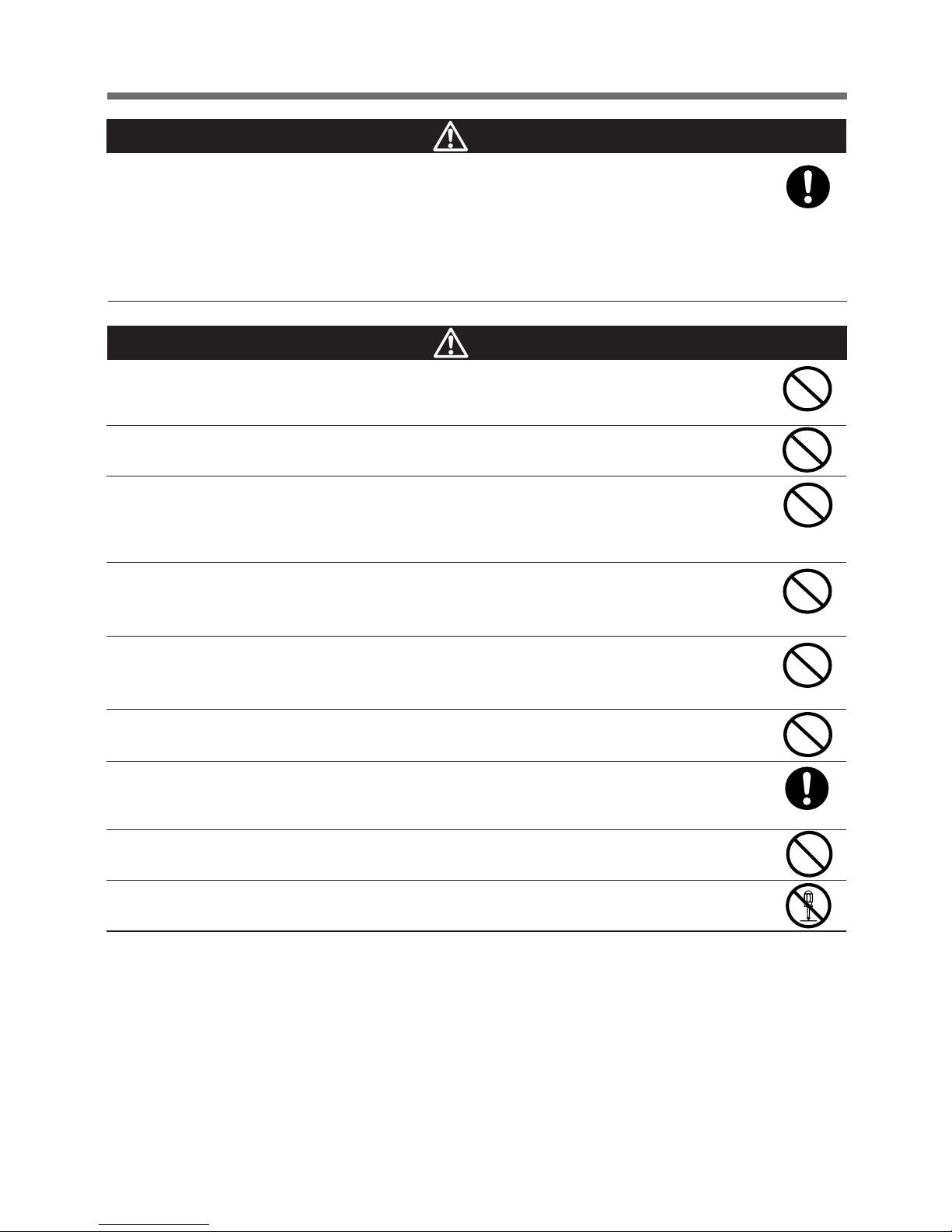
● The safety symbols used in this manual and their meanings are as follows.
* Property damage means damage to houses/household effects, livestock, and pets.
Notice that do's and don'ts of "Caution" may bring about a serious accident according to the circumstances.
These do's and don'ts are critical and must be observed strictly.
Warnings
Read this instruction manual before installation and
use to ensure that you fully understand the critical
do's and don'ts of your UPS.
Misuse may cause injury or property damage.
Do not disassemble, repair, and/or modify your UPS.
● Doing so may cause an electric shock or fire.
If battery liquid leaks from the UPS, do not touch it.
● Doing so can lead to blindness and/or or burns.
● If the liquid gets in eyes or spills on your skin, wash with clean water and consult a doctor.
When replacing the battery, do not insert anything metal into the battery.
● An electric shock or short may occur.
Unpacking and carrying the UPS requires the following number of people:
BN100XR/BN150XR: 2 or more people
BN240XR/MB240XR: 3 or more people
● The UPS is heavy, so be careful when unpacking and carrying it.
Keep the weight in mind when unpacking and carrying the UPS.
Place and run the UPS on a structurally sound and level base.
● If the UPS falls over, or if you drop it, it may cause injury.
● The weight of the UPS
BN100XR: 20kg BN150XR: 20kg BN240XR: 38kg MB240XR: 29kg (add-on battery unit)
● If the UPS falls, immediately stop using it, inspect it, and repair it if necessary.
Do not add the UPS where very high reliability and safety are required as
listed below. (The UPS is designed and manufactured for uses with OA
equipment, such as personal computers.)
● Medical devices and/or systems that support life directly
● Applications that may adversely affect the safety of people (for example, the operation and control of auto-
mobiles and elevators)
● Applications that adversely affect the maintenance of utilities in the event of failure (for example, critical
computer systems and trunk lines)
● Applications with the similar level of importance
Warnings (uses of the UPS)
: Indicates prohibited action (don'ts). For example, indicates that disassembly is prohibited.
: Indicates necessary action (do's). For example,
indicates that grounding is necessary.
Cautions (installation)
Page 6
4
Directions for safe use
Keep packing materials, including plastic bags and film, out of the reach of
children
● Should children swallow or put their head into the packing materials, there is danger of suffocation.
Provide secure grounding
● Earth the ground terminals of the UPS and devices connected to the UPS. (See "2. Installation
and connection" on page 17)
You may receive an electric shock in the event of trouble or power failure. When both the UPS
and devices are not grounded and you touch both, you may receive an electric shock.
● For BN100XR/BN150XR, when you use a 3-pin to 2-pin plug for the AC Input Plug, be sure to
perform grounding before putting the AC Input Plug in a wall outlet (commercial power). On the
other hand, be sure to disconnect the grounding terminal after removing the AC Input Plug from
a wall outlet (commercial power).
● Connect the UPS grounding terminal to a grounded-type wall outlet (commercial power) to ensure
that the Power Line Surge Protection works as intended.
Do not use the UPS where the maximum temperature exceeds 40°C.
● Battery deterioration will occur rapidly.
● Doing so may result in a failure or malfunction of the UPS.
Do not exceed the specified ranges in the operating and storage
environments.
Do not install or store the UPS in the following types of places.
● Places with high temperatures, low temperatures, or high humidity
● Places that receive direct sunlight
● Places that are directly heated by a stove or other heat source
● Places where the UPS may experience vibration or physical shock
● Places where there is dust, corrosive gas, salt, or flammable gas
● Outdoors
Placing the UPS in these types of areas may result in malfunction, deterioration, and/or fire.
Do not obstruct the air inlets and outlets on the sides and rear of the UPS.
Do not place the UPS in an enclosed space or cover the UPS.
● Doing so may lead to abnormal overheating or fire.
● Temperature will increase inside the UPS and may cause a failure of the UPS and battery
deterioration.
● Install the UPS 5cm or further away from the wall.
Do not install the UPS in other orientations.
Do not install the UPS on a structurally unsound base.
● See "2-2 Installation" on page 20.
● If the UPS falls over, or if you drop it, injury may result.
Do not clip the cables, and do not use when the cables are bundled.
● If the cables become damaged or overheated, there is a danger of electric shock or fire.
● If the cables become damaged, immediately stop using the UPS, and make the necessary
repairs.
Do not connect a device such as a voltage transformer or isolated
transformer to the output side.
● Overcurrent may damage the UPS.
● Even when connected to the input side, the UPS may fail or malfunction. Make sure to check the
operation before use.
Cautions (installation)
Page 7
5
Directions for safe use
Cautions (installation)
When performing rack installation, ensure that the UPS is supported and
stabilized by using both the support angles and the table clamps that were
included.
When connecting a battery unit and/or adding another battery unit, be sure
to place the battery unit in a position lower than the main unit.
● When installing on a rack, make sure that the UPS is supported by the each unit individually.
● When installing on a rack, make sure to use the support angles and table clamps included with the
product. Without the support angles, the front clamp alone cannot support the weight of the UPS.
● The mass of the UPS: BN100XR: 20 kg BN150XR: 20 kg
BN240XR: 38 kg MB240XR: 29 kg (add-on battery unit)
In a case where the UPS is to be mounted on a rack, place it on the lowest
part of the rack.
● Dropping it may result in injury.
Be sure to use the supplied mounting screws.
● Screws other than those supplied may not be strong enough to support the UPS, causing it to fall.
Do not place things on the units.
● Doing so may make battery change difficult due to the load.
Connect the UPS to a wall outlet (commercial power) with a current capacity
greater than the maximum input current of the UPS.
● Electrical wiring may become hot.
● When connected to a rated capacity device, the maximum current that can flow is as follows:
BN100XR: 13.5A, BN150XR: 18A, and BN240XR: 27A.
Be sure to put the input plug of the UPS in a 100V AC (50/60 Hz) wall outlet
(commercial power).
● Connecting the input plug to a wall outlet (commercial power) of a different voltage may cause a
fire.
● The UPS may fail.
When using the 15A plug (NEMA 5-15P) with the BN150XR
The maximum capacity that can be connected to the output is about 1100VA1000W.
● Power consumption over 1100VA/1000W results in an input current of more than 15A, which can
lead to overheating or fire.
● When the "Input over 15A" display appears, replace it with a 20A plug.
When replacing the input plug for the BN150XR, make sure to follow the
connection directions correctly, and make sure not to mistake the colors of
the plug receptacle and wire.
See "2-4. Connection of AC input cable" on page 24.
● Doing so may cause a leakage or an electric shock.
Do not connect devices that exceed the output capacity of the UPS.
You can add extra devices with a plug strip. Note that the plug strip does not
permit the connection of devices that exceed the current capacity of the
plug strip.
● The UPS may detect overload and stop the output.
● The plug strip cord may heat up and could lead to a fire.
Do not connect to a device (such as a dryer) that uses half-wave rectification
in which AC power supply current flows in half-cycles only.
● The UPS may fail.
Cautions (connection)
Page 8
6
Directions for safe use
In a case where the Battery Replacement Lamp comes on or the backup
time becomes shorter than the required backup time, replace the battery
pack with a new one while the UPS is running, or stop the UPS and discard
the old battery pack.
● The continuous operation of the UPS may result in fire.
● For further information on how to inspect the battery, see "5. Maintenance and inspection" on
page 37.
When you notice abnormal sound or smell, smoke, or liquid coming from
the inside of the UPS, immediately turn OFF the power switch (
) and
remove the AC Input Plug from the wall outlet (commercial power).
● Continuous operation under the abnormal conditions may cause a leakage of current or fire.
● If you notice the abnormal conditions, never operate the UPS, and contact us or the distribu-
tor from which you purchased your UPS for inspection and repair.
● Your UPS must permit instant removal of the AC Input Plug from a wall outlet (commercial
power) at the onset of a failure.
Do not place objects on the UPS and do not drop metal objects into the
UPS.
● Doing so may cause distortion and/or damage to the top case of the UPS or an internal circuit
failure, which may lead to a fire.
Do not place the UPS in an enclosed space or put a cover over the UPS.
● Doing so may lead to abnormal overheating and/or fire.
Do not spill water on the UPS or get it wet.
● Doing so may cause an electric shock or fire.
● If the UPS gets wet, immediately stop using it, inspect it, and make repairs if necessary.
Do not insert metal objects into the output receptacles of the UPS.
● Doing so may cause an electric shock.
Do not insert metal objects into the battery connector or add-on battery
connector. Do not short-circuit the connector terminals.
● Doing so may cause an electric shock.
● There is a risk of combustion, battery explosion, and burn injury.
Cautions (use)
* The table on the left shows the estimated life expect-
ancy of a battery pack in normal usage conditions.
This is not the warranty period.
Ambient temperature
20°C
30°C
Estimated life expectancy
2 to 3 years
1 to 1.5 years
Page 9
7
Directions for safe use
Before maintaining devices connected to the UPS, turn off the UPS and
remove the AC Input Plug from the wall outlet (commercial power).
● Even if you remove the AC Input Plug during the operation of the UPS, the backup function of
the UPS keeps feeding power through the power supply output receptacle of the UPS.
● In a case where the scheduled operation is ON and the AC Input Plug of the UPS is put in a
wall outlet (commercial power), the UPS starts feeding power at the starting time of the
scheduled operation.
Cautions (maintenance)
Do not short-circuit the battery with a metal object.
● Doing so may result in burn injury or fire.
● Even in a dead battery, there is some current remaining.
Do not toss a battery into a fire. Do not try to break a battery.
● The battery may explode or dilute sulfuric acid may leak.
Do not use any batteries other than those specified.
● Doing so may lead to a fire.
● Battery pack product models: BP150XR (for BN100XR, BN150XR), BP240XR (for BN240XR,
MB240XR)
Do not use a new battery and an old battery at the same time (when adding
BN240XR battery).
● Rapid deterioration of battery may occur, and dilute sulfuric acid may leak.
Do not drop the battery, and make sure that it does not receive any strong
impact.
● Dilute sulfuric acid may leak.
Do not replace the battery in a place near flammable gas.
● A spark may occur when connecting the battery, and lead to a fire.
Replace a battery on a structurally sound base.
● Hold the battery securely with both hands to avoid dropping.
● Failure to do so may result in injury due to the battery falling, burns, or injury.
If there is liquid coming from the replaced battery pack, do not touch it.
● If touched, the liquid (dilute sulfuric acid) may cause burn injury or blindness.
Do not disassemble or modify the battery.
● Doing so may cause a leakage of dilute sulfuric acid, which may cause blindness and burns.
Cautions (battery replacement)
Page 10

8
Directions for safe use
Pb
Notes
After purchasing the UPS, charge the battery until the battery charge indication shows
that the battery is fully charged.
● If you do not use your UPS for a long time after purchase, the battery may deteriorate and become unusable.
● After inserting the AC Input Plug of the UPS into a wall outlet (commercial power), the battery automatically
begins to charge.
Before storing the UPS, charge the battery until the battery charge indication shows
that the battery is fully charged.
● In a case where you do not use the battery, it discharges naturally and goes into over discharge status
after it is left for a long time. The backup time may become shorter or the battery may become unusable.
● The maximum possible storage period for the battery installed in the UPS is 6 months (after being fully
charged).
● If the storage period is to exceed 6 months, recharge the battery before 6 months have passed by con-
necting the AC Input Plug to a wall outlet (commercial power).
● When storing the UPS, make sure that power switch ( ) is turned OFF.
Do not create a short between the output lines of the UPS, or a ground fault between
the output lines and the ground.
● The UPS may fail.
When the UPS is in operation, do not insert the AC Input Plug into the Power Supply
Output Receptacle of the same UPS.
● The UPS may fail.
Shut down the UPS before cutting commercial power supply.
If the power switch cannot be turned OFF, perform an auto shutdown of the UPS
using the UPS monitoring software with the minimum required backup time.
● The UPS goes into Battery mode whenever commercial power is cut. By continuing to run the devices on the
battery and recharging the battery, the life expectancy of the battery is significantly shortened.
The less you repeat charges and discharges, the longer the life expectancy of the battery will become.
Do not connect a page printer to the UPS.
● The peak current of the page printer is large, so it may be detected as an overcurrent, or the resulting
instantaneous voltage drop may be detected as a power failure.
● Operation may switch between Line mode and Battery mode, reducing battery life.
If the unit is used with an inductive device such as a coil or motor, check
the operation beforehand.
● With some types of devices, the effect of inrush current may cause this unit to stop operating properly.
Do not perform a withstand voltage test.
● The power input circuit has a built-in surge absorber element. A withstand voltage test may break it.
● When performing an insulation resistance test, conduct it in the 250V DC range.
Recycling and discarding the battery
● The UPS has a lead acid battery. The battery is a recyclable and valuable resource. We need
your cooperation in recycling old batteries, batteries that you replace with a new batteries, and
the batteries you used to discard.
Installation and storage places
● Do not install or store the UPS in a place exposed to direct sunlight.
High temperatures may cause the battery to deteriorate and become unusable.
Page 11

9
Directions for safe use
Explanations
Usual operating method
● You may keep the UPS running without shutting down, or you may turn off the UPS each time the devices
connected the UPS are turned off.
You can choose either way, depending on which is convenient.
● When connected to commercial power, the battery starts charging.
Terminating backup operation
● In the case of an extended power failure, the battery keeps discharging until power supply from the UPS
stops. Before that happens, turn off your computer in the usual manner (including data backup).
Rebooting
● If the battery discharges completely during a power failure, the UPS stops. After the recovery from a failure
of the power supply (for example, a power failure), the UPS automatically restarts and starts to feed power.
If you do not want to run the devices connected to the UPS, keep the devices turned off.
● Using UPS monitoring software, automatic restart can be disabled.
The USB and RS-232C ports cannot be used simultaneously.
● The UPS monitoring software and can be used with either the USB or RS-232C ports of the UPS, but they
both cannot be used at the same time.
Scheduled operation using UPS monitoring software
● When scheduled operation is being used, if commercial power is stopped during the scheduled shutdown
period, set the period of time until the start of next operation at about one month.
The timer is activated by the built-in battery for the period of time that the commercial power supply input is
stopped.
If the timer stops, operation start cannot be performed according to schedule.
Using UPS service of Windows NT
● If you are using Windows NT Server, make the settings using the server menu as shown below. An incorrect
setting of the remote UPS shutdown the UPS will be unable to perform backup in the event of a power failure.
For more detailed information, refer to the Windows NT 4.0 manual or the Windows NT 4.0 help file.
The signal settings are as follows:
Power supply shutdown signal: Negative (for initial value, Windows NT server is set as negative, and
OS2Lan server is set as positive)
Battery weak/dead signal: Negative (for initial value, Windows NT server is set as negative, and
OS2Lan server is set as negative)
Remote UPS shutdown: Positive (for initial value, Windows NT server is set as negative, and
OS2Lan server is set as negative)
● For Netware users, call up the command input screen, and enter the following to load a UPS module into the
file server.
LOAD UPS TYPE=6 PORT=__ REV=2
After this is input, press the Enter key.
In the command line, after "PORT=", enter the number of the serial port that is connected to the UPS. (1 or 2)
Page 12

10
Directions for safe use
Explanations
Auto restart after shutdown processing by UPS monitoring software
● In the event of a power failure, some PC models (see *1 below) automatically restart immediately after the
completion of the OS shutdown processing by the UPS monitoring software.
In this case, the UPS stops during restart or after startup, possibly damaging files and/or the hard disk.
This problem can be avoided by disabling POWER MANAGEMENT in the BIOS settings.
*1) PC models: This problem has been reported with MICRON's Millennia Mme.
● When the PC does not start up automatically, select the "System startup at power restoration" setting (example:
"Restore On AC/Power Loss") in the BIOS settings of your PC, and change to a "System startup after power
restoration" setting (example: "Power On"). Individual BIOS setting methods and/or displays may differ
depending on the PC. For more information, consult your PC instruction manual or contact the technical
support center for your PC.
● When considering a system with automatic startup at power restoration, choose a PC that satisfies the
condition below. For more information on PC operation when input power is supplied, consult your PC
instruction manual or contact the PC technical support center.
<Condition>
Without having the power switch pressed, the PC starts up when input power is supplied.
● After shutdown processing, the UPS restarts automatically and supplies power once power is restored. If
you do not want the devices connected to the UPS to start up, turn off their switches in advance.
● The automatic restart setting can be disabled in the included UPS monitoring software.
Page 13

11
1. Preparation
Keep the weight in mind when unpacking and carrying the UPS.
Place and run the UPS on a structurally sound and level base.
● If the UPS falls over, or if you drop it, it may cause injury.
● The weight of the UPS
BN100XR/BN150XR: 20kg BN240XR: 38kg MB240XR: 29kg (add-on battery unit)
● If the UPS falls, immediately stop using it, inspect it, and repair it if necessary.
1-2 Checking the accessories
If you should notice defects or anything wrong, please contact your distributor at once.
Cautions
1. Preparation
1-1 Unpacking the UPS
20A AC plug
USB cable for UPS
monitoring software
EIA 19-inch rackmount
fittings and supports
Upright stand
Battery unit
connection cable
Signal cable
(modular cable for battery unit)
Connect to the battery unit connecting cable
Upright coupling plate
Accessories Quantity BN100XR BN150XR BN240XR MB240XR
1. Main unit 1 ○○○○
2. UPS monitoring software
1 set ○○○ --
(CD-ROM, RS232C cable, etc.)
3.
USB cable for UPS monitoring 1
○○○ --
software
4. 3P-2P adapter plug 1 ○○ -- --
5. 20A AC plug 1 -- ○ -- --
6. Upright stand 1
-- --
○
--
7
. Battery unit connection cable set 1 -- -- -- ○
8. Signal cable
1
-- -- -- ○
(modular cable for battery unit)
9. Upright coupling plate 1
-
-- -- --
○
10. EIA19-inch rackmount fittings
1 set ○○○
○
and supports
11. Instruction manual (Japanese) 1 ○○○○
12. Instruction manual (English) 1 ○○○○
13. Warranty 1 ○○○○
14.
User registration card 1 ○○○ --
15. Label (Identification of
operating
1 ○○○ --
condition)
Page 14
12
1. Preparation
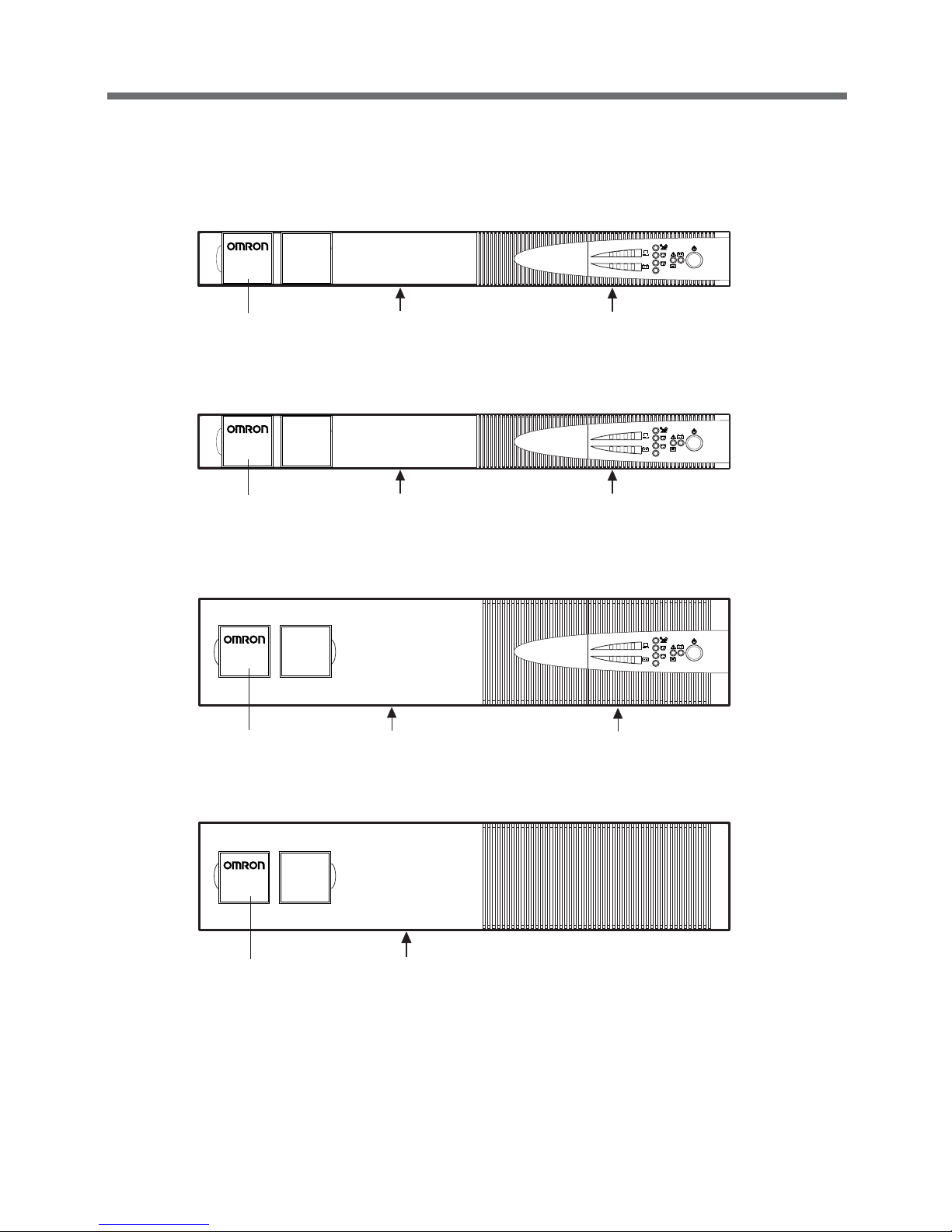
1-3 Part names
1. Front panel
● BN100XR
Note: There is a fixing screw for the battery panel beneath the logo plate.
● BN150XR
Note: There is a fixing screw for the battery panel beneath the logo plate.
● BN240XR
● MB240XR (Add-on battery)
Note: There is a fixing screw for the battery panel beneath the logo plate.
BN150XR
BACK UP POWER SUPPLY
BN240XR
AC115V
OUTPUT
B
25% 50% 75% 100%
C
AC115V
OUTPUT
B
25% 50% 75% 100%
C
BN100XR
BACK UP POWER SUPPLY
AC115V
OUTPUT
B
25% 50% 75% 100%
C
BATTERY UNIT
MB240XR
BACK UP POWER SUPPLY
Logo plate
Battery panel
Control panel
Logo plate Battery panel
Control panel
Logo plate
Outer panel
Logo plate
Battery panel
Control panel
Page 15
13
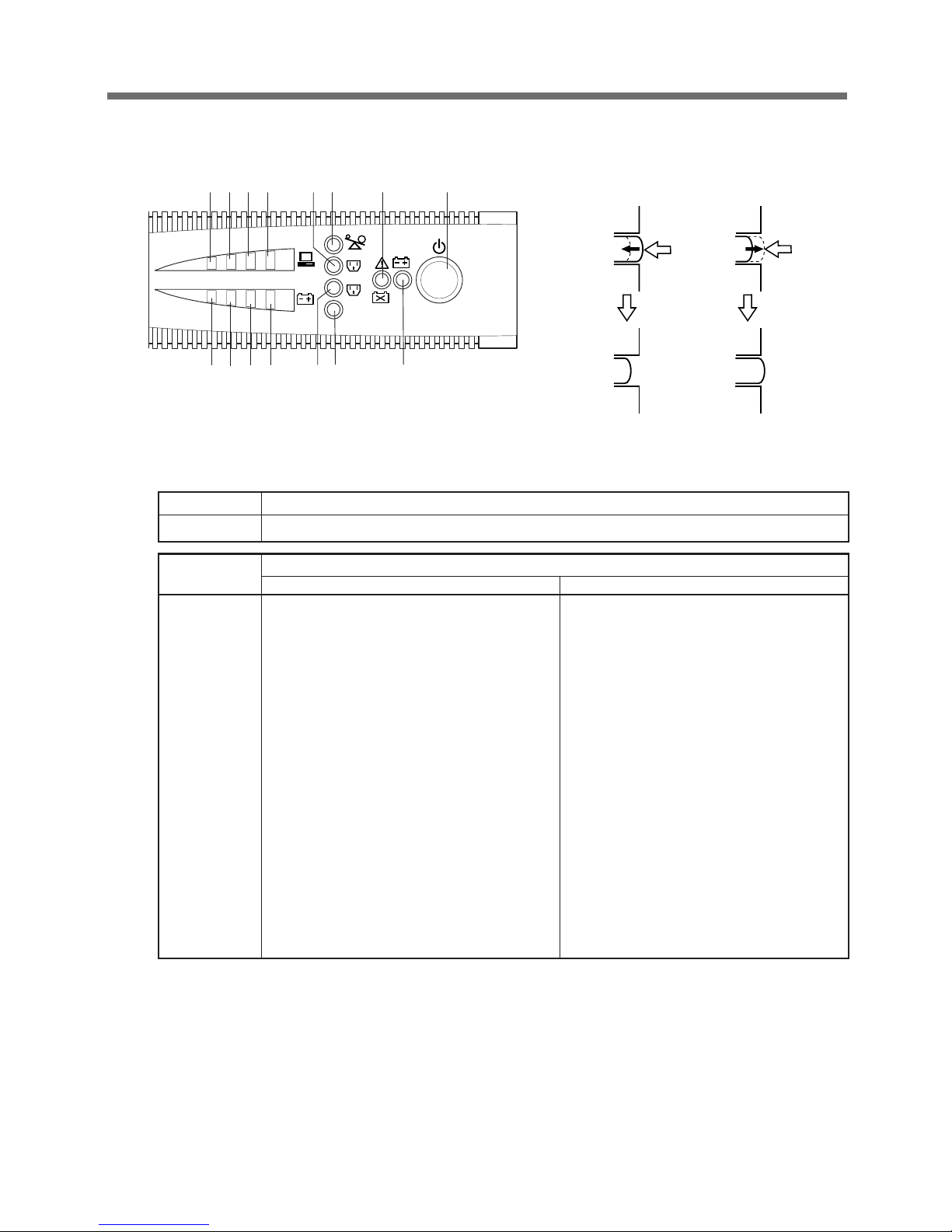
1. Preparation
AC115V
OUTPUT
B
25% 50% 75% 100%
C
ACDEH1 H2 H3
H4
I 1 I 2 I 3
I 4
FG B
Power switch
To turn ON To turn OFF
ON OFF
Press
Press
Switch FUNCTION
A Power switch
Indication
Lit
lamp
Continuous illumination Blinking display
A (green)
Power supply output/receptacle A output indication Charging (blinks once every 10 seconds)
B (yellow) Battery mode indication Testing the battery (blinks once per second)
C (red) Warning indication (failure)
Battery deterioration indication (blinks once every
two seconds)
D (yellow) Input over 15A indication (BN150XR only) Overload indication (once every 0.5 second)
E (green) Output indication for output receptacle B
F (green) Output indication for output receptacle C
G (yellow) 115V AC output mode indication
H1 to H4 (green)
Connection capacity indication
H1 0 to 25%
H2 25 to 50%
H3 50 to 75%
H4 75 to 100%
I1 to I4 (green) Battery charge/remaining capacity indicator
(approximate value)
I10 to 25%
I2 25 to 50%
I3 50 to 75%
I4 75 to 100%
● Control panel (BN150XR/BN240XR)
Page 16
14
1. Preparation
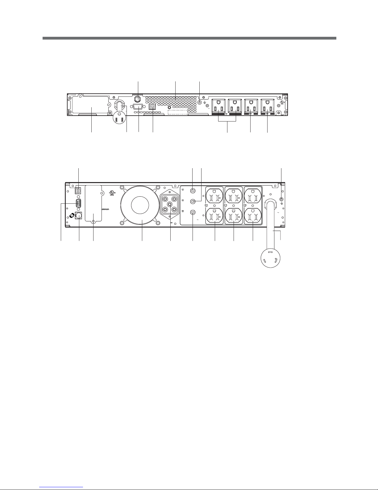
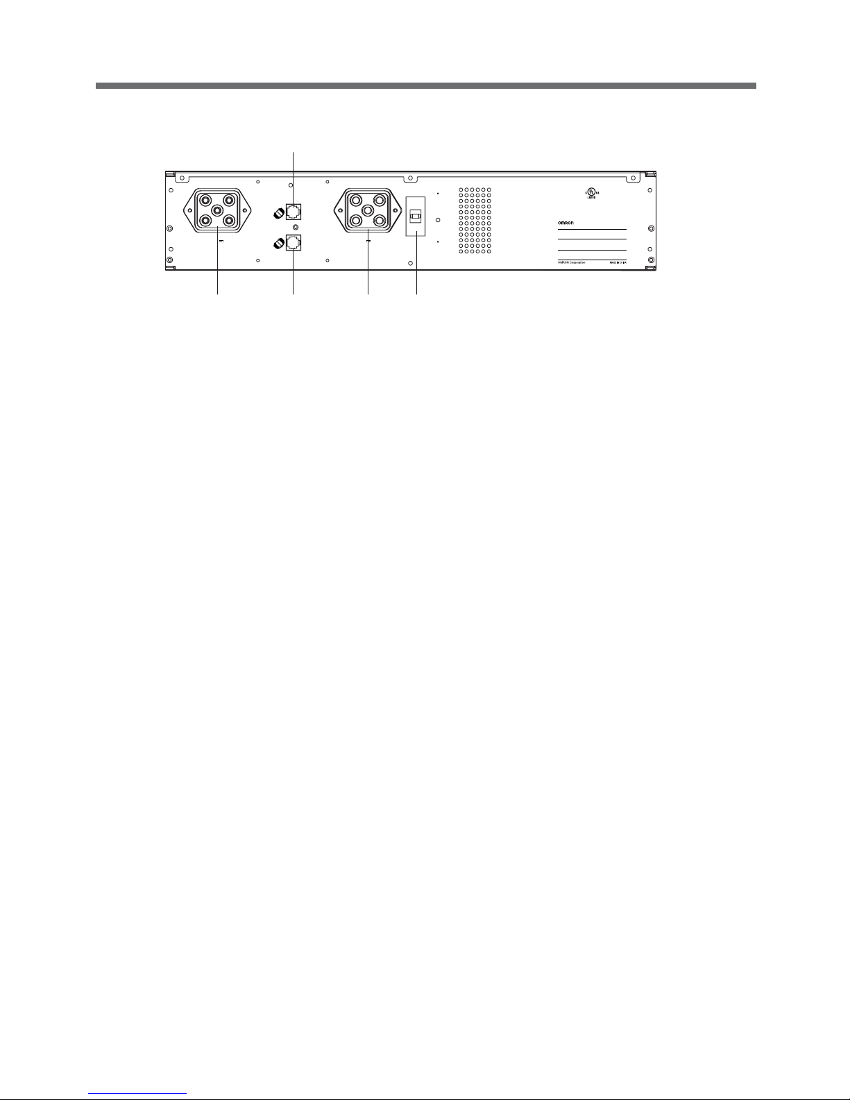
2. Rear panel
●BN100XR/BN150XR
●BN240XR
A AC input cable
BN100XR: NEMA 5-15 (15A) plug
BN150XR: NEMA 5-15 (15A) plug
BN240XR: NEMA L5-30 (30A) plug
B Input overcurrent protection
BN100XR: 15A BN150XR: 20A BN240XR has built-in fuse (30A)
CGrounding screw terminal (FG)
D1 Output receptacle A
BN100XR (10A max.) BN150XR (15A max.) BN240XR (20A max.)
D2 Output receptacle B (Delayed output at startup/ON-OFF control possible)
BN100XR (10A max.) BN150XR (15A max.) BN240XR (20A max.)
D3 Output receptacle C (Delayed output at startup/ON-OFF control possible)
BN100XR (10A max.) BN150XR (15A max.) BN240XR (20A max.)
E USB interface
F RS232C interface
G Option card slot
H1 Output receptacle A overcurrent breaker (20A)
H2 Output receptacle B overcurrent breaker (20A)
H3 Output receptacle C overcurrent breaker (15A)
I Add-on battery (MB240XR) connector
J Add-on battery (MB240XR) signal connector
K Air vent
INPUT AC100V
50/60Hz 15A MAX.
INPUT AC100V
50/60Hz 15A MAX.
INPUT PROTECTION
15A
RS232C
USB
SER. :
1
OUTPUT
AC100-115V
50/60Hz
15A/1000W MAX.
A
34Z5
U.P.S.
MODEL : BN150XR
B C
B
KC
GAFE D
1
D2D
3
INPUT AC100V
50/60Hz 30A MAX.
34Z5
U.P.S.
無停電電源装置
SER.
MODEL : BN240XR
BATTERY CONNECTOR
Volt : 72Vdc
XX A
20A MAX.
A
C
20A MAX.
B
15A MAX.
C
BA
USB
RS232C
TO BATTERY
CABINET
OUTPUT
AC100-115V
50/60Hz
24A/2000W MAX.
EH
1H2
C
AD
3
D
2
D
1
H
3
KGJ
F
I
Page 17
15
1. Preparation
●MB240XR
A Add-on battery connector (to BN240XR/previously connected MB240XR)
B Add-on battery (MB240XR) connector (to additionally connected MB240XR)
C1, C2 Add-on battery signal connector
D Battery overcurrent breaker (63A)
(Switch “ON” the breaker when operating.)
34Z5
U.P.S.
BATTERY SUPPLY
MODEL : MB240XR
SER.
EXTENDED BATTERY FOR
OMRON UPS BN240XR
Volt : 72Vdc
Ah : 9Ah
FOR DETECTION OF No. OF
BATTERY CABINET ONLY
DC BRAKER
XXA XXXVdc
OFF
ON
BATTERY CONNECTOR
Volt : 72Vdc XXA
TO UPS or TO OTHER
BATTERY MODULES
BATTERY CONNECTOR
Volt : 72Vdc XXA
TO UPS or TO OTHER
BATTERY MODULES
A C2
C1
B D
Battery unit
Page 18
16
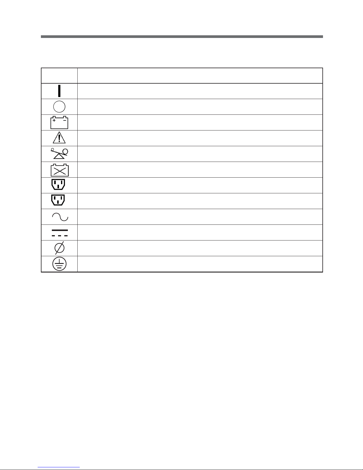
1. Preparation
Symbol Description
UPS is ON.
UPS is OFF.
Add-on battery unit is connected to the UPS.
An error occurred with the UPS.
Connection overload. Output capacity exceeded by connected devices.
Batteries at end of useful life. Necessary to replace the batteries.
Output receptacle B is ON.
Output receptacle C is ON.
AC input / output power supplied.
DC power supplied.
Phase of AC power, 1
φ
: Single phase.
Indicates earth ground.
C
1-4 Explanation of symbols used on unit
B
Page 19

17
2. Installation and connection
Cautions (Compulsory (do's))
2. Installation and connection
2-1
Precautions and notes on installation and connection
Precautions and notes on installation and connection are given below. Be sure to read them for correct use.
Keep the weight in mind when unpacking and carrying the UPS.
Place and run the UPS on a structurally sound and level base.
● If the UPS falls over, or if you drop it, it may cause injury.
● The weight of the UPS
BN100XR: 20kg BN150XR: 20kg BN240XR: 38kg MB240XR: 29kg (add-on battery unit)
● If the UPS falls, immediately stop using it, inspect it, and repair it if necessary.
Keep packing materials, including plastic bags and film, out of the reach of
children
● Should children swallow or put their head into the packing materials, there is danger of suffocation.
Provide secure grounding
● Earth the ground terminals of the UPS and devices connected to the UPS.
You may receive an electric shock in the event of trouble or power failure. When both the UPS
and devices are not grounded and you touch both, you may receive an electric shock.
● For BN100XR/BN150XR, when you use a 3-pin to 2-pin plug for the AC Input Plug, be sure to
perform grounding before putting the AC Input Plug in a wall outlet (commercial power). On the
other hand, be sure to disconnect grounding terminal after removing the AC Input Plug from a
wall outlet (commercial power).
● Connect the UPS grounding terminal to a grounded-type wall outlet (commercial power) to ensure
that the Power Line Surge Protection works as intended.
Connect the UPS to a wall outlet (commercial power) with a current capacity
greater than the maximum input current of the UPS.
● Electrical wiring may become hot.
● When connected to a rated capacity device, the maximum current that can flow is as follows:
BN100XR: 13.5A, BN150XR: 18A, and BN240XR: 27A.
Be sure to put the input plug of the UPS in a 100V AC (50/60 Hz) wall outlet
(commercial power).
● Connecting the input plug to a wall outlet (commercial power) of a different voltage may cause a
fire.
● The UPS may fail.
Page 20

18
2. Installation and connection
Cautions (Prohibition (don'ts))
Do not obstruct the air inlets and outlets on the sides and rear of the UPS.
Do not place the UPS in an enclosed space or cover the UPS.
● Doing so may lead to abnormal overheating or fire.
● Temperature will increase inside the UPS and may cause a failure of the UPS and battery
deterioration.
● Install the UPS 5cm or further away from the wall.
Do not use the UPS where the maximum temperature exceeds 40°C.
● Battery deterioration will occur rapidly.
● Doing so may result in a failure or malfunction of the UPS.
Do not exceed the specified ranges in the operating and storage
environments.
Do not install or store the UPS in the following types of places.
● Places with high temperatures, low temperatures, or high humidity
● Places exposed to direct sunlight
● Places that are directly heated by a stove or other heat source
● Places where the UPS may be exposed to vibration or physical shock
● Places where there is dust, corrosive gas, salt, or flammable gas
● Outdoors
● Placing the UPS in these types of areas may result in malfunction, deterioration, and/or fire.
Do not install the UPS in other orientations.
Do not install the UPS on a structurally unsound base.
● See "2-2 Installation" on page 20.
● IP the UPS falls over, or if you drop it, injury may result.
Do not connect devices that exceed the output capacity of the UPS.
You can add extra devices with a plug strip. Note that the plug strip does not
permit the connection of devices that exceed the current capacity of the
plug strip.
● The UPS may detect overload and stop the output.
● The plug strip cord may heat up and could lead to a fire.
Do not connect to a device (such as a dryer) that uses half-wave rectification
in which AC power supply current flows in half-cycles only.
● The UPS may fail.
Do not clip the cables, and do not use when the cables are bundled.
● If the cables become damaged or overheated, there is a danger of electric shock or fire.
● If the cables become damaged, immediately stop using the UPS, and make the necessary
repairs.In a case where the UPS is to be mounted on a rack, place it on the lowest part of the
rack.
Do not connect a device such as a voltage transformer or isolated
transformer to the output side.
● Overcurrent may damage the UPS.
● Even when connected to the input side, the UPS may fail or malfunction. Make sure to check
the operation before use.
Page 21

19
2. Installation and connection
Notes
Do not create a short between the output lines of the UPS, or a ground fault between
the output lines and the ground.
● The UPS may fail.
When the UPS is in operation, do not insert the AC Input Plug into the Power Supply
Output Receptacle of the same UPS.
● The UPS may fail.
Shut down the UPS before cutting commercial power supply.
If the power switch cannot be turned OFF, perform an auto shutdown of the UPS
using the UPS monitoring software with the minimum required backup time.
● The UPS goes into Battery mode whenever commercial power is cut. By continuing to run the devices on the
battery and recharging the battery, the life expectancy of the battery is significantly shortened.
The less you repeat charges and discharges, the longer the life expectancy of the battery will become.
Do not connect a page printer to the UPS.
● The peak current of the page printer is large, so it may be detected as an overcurrent, or the resulting
instantaneous voltage drop may be detected as a power failure.
● Operation may switch between Line mode and Battery mode, reducing battery life.
If the unit is used with an inductive device such as a coil or motor, check the operation
beforehand.
● With some types of devices, the effect of inrush current may cause this unit to stop operating
properly.
Do not perform a withstand voltage test.
● The power input circuit has a built-in surge absorber element. A withstand voltage test may break it.
● When performing an insulation resistance test, conduct it in the 250V DC range.
Installation and storage places
● Do not install or store the UPS in a place exposed to direct sunlight.
High temperatures may cause the battery to deteriorate and become unusable.
Page 22

20
2. Installation and connection
2-2 Installation
The UPS permits the following installing methods. Choose the one best suited for the environment.
1. Rackmount installation
2. Stationary installation
● Horizontal
● Upright intatllation for BN240XR/MB240XR
1. Rackmount installation (EIA 19-inch rack/server rack)
Cautions
When performing rack installation, ensure that the UPS is supported and
stabilized by using both the support angles and the table clamps that were
included.
When connecting a battery unit and/or adding another battery unit, be sure
to place the battery unit in a position lower than the main unit.
● When installing on a rack, make sure that the UPS is supported by the each unit individually.
● When installing on a rack, make sure to use the support angles and table clamps included with
the product. Without the support angles, the front clamp alone cannot support the weight of the
UPS.
● The mass of the UPS: BN100XR: 20 kg BN150XR: 20 kg
BN240XR: 38 kg MB240XR: 29 kg (add-on battery unit)
In a case where the UPS is to be mounted on a rack, place it on the lowest
part of the rack.
● Dropping it may result in injury.
Be sure to use the supplied mounting screws.
● Screws other than those supplied may not be strong enough to support the UPS, causing it to fall.
● Rack installation for BN100XR/BN150XR
Follow steps 1 through 6 for installation.
Make sure to use the support clamps (support angles, front support clamp
33
33
3,
rear support clamp
66
66
6).
2
6
6
1
2
2
2
4
3
5
5
3
B
N
1
5
0
X
R
B
A
C
K
U
P
P
O
W
E
R
S
U
P
P
L
Y
A
C
1
1
5
V
O
U
T
P
U
T
B
2
5
%
5
0
%
7
5
%
1
0
0
%
C
Page 23

21
2. Installation and connection
● Rack installation for BN240XR (MB240XR)
Follow steps 1 through 6 for installation.
Make sure to use the support clamps (support angles, front support clamp
33
33
3,
rear support clamp
66
66
6).
2
6
B
N
2
4
0
X
R
B
A
C
K
U
P
P
O
W
E
R
S
U
P
P
L
Y
6
3
5
5
3
A
C
1
1
5
V
O
U
T
P
U
T
B
2
5
%
5
0
%
7
5
%
1
0
0
%
C
1
2
2
2
4
Two types of nuts have been included for
22
22
2 and
55
55
5.
Use the type that suits the rack.
Page 24

22
2. Installation and connection
2. Stationary installation
Perform installation only as shown in the diagrams below.
● Horizontal installation
This product does not have rubber feet, and there are no screw threads on the bottom side. For stationary
horizontal installation, make sure that this product does not slide or fall.
BN100XR/BN150XR
BN240XR
● Upright installation (BN240XR/MB240XR)
BN100XR/BN150XR can not be installed upright.
(1) Upright installation for BN240XR
Use the stand that was included with this
product.
(2) Upright installation for BN240XR +
MB240XR
Use the included coupling plate to join the
BN240XR and the MB240XR, and then attach
the stand to both sides.
BN150XR
BACK UP POWER SUPPLY
AC115V
OUTPUT
B
25% 50% 75% 100%
C
BN240XR
BACK UP POWER SUPPLY
AC115V
OUTPUT
B
25% 50% 75% 100%
C
B
N
2
4
0
X
R
B
A
C
K
U
P
P
O
W
E
R
S
U
P
P
L
Y
Do not place things on the units.
● Doing so may make battery change difficult due to the load.
Coupling plate
I
N
P
U
T
A
C
1
0
0
V
5
0
/
6
0
H
z
3
0
A
M
A
X
.
34
Z5
U
.P
.S
.
BA
T
TER
Y
SU
P
PL
Y
M
O
DE
L : MB
240
X
R
SE
R.
EX
T
EN
D
E
D B
A
TT
E
RY
F
OR
O
M
R
O
N
U
P
S BN
24
0XR
Vo
lt : 7
2V
dc
A
h : 9
Ah
バ
ッ
テ
リユ
ニ
ッ
ト
F
OR
DE
TE
CT
IO
N
OF
No
. OF
B
AT
TE
R
Y
CA
BIN
ET
O
NLY
D
C BR
A
KE
R
XX
A
X
X
XV
d
c
O
FF
O
N
BA
TT
ER
Y C
ON
NE
C
TO
R
V
o
lt : 72V
dc
X
X
A
TO
UP
S
or TO
O
TH
E
R
B
AT
T
ER
Y
M
OD
UL
ES
B
AT
TE
R
Y CO
N
N
EC
TO
R
V
olt : 7
2
Vdc
XX
A
TO
U
P
S
or T
O OT
H
E
R
BA
TT
ER
Y
MO
DU
LES
3
4
Z
5
U
.
P
.S
.
無停鏑d
撞d
源装鱈u
S
E
R
.
M
O
D
E
L
:
B
N
2
4
0
X
R
B
A
T
T
E
R
Y
C
O
N
N
E
C
T
O
R
V
o
l
t
:
7
2
V
d
c
X
X
A
2
0
A
M
A
X
.
A
A
2
0
A
M
A
X
.
B
1
5
A
M
A
X
.
C
1
B
C
U
S
B
R
S
2
3
2
C
T
O
B
A
T
T
E
R
Y
C
A
B
I
N
E
T
O
U
T
P
U
T
A
C
1
0
0
1
1
5
V
5
0
/
6
0
H
z
2
4
A
/
2
0
0
0
W
M
A
X
.
1
Page 25

23
2. Installation and connection
2-3 Adding a battery unit (MB240XR)
• It is possible to connect up to two add-on battery units (MB240XR) to the BN240XR.
• It is possible to perform connection while the main unit (BN240XR) is plugged in.
When connected to a 2.4KVA/2000W device, the backup time for one add-on battery is 10 minutes, and
the backup time for two add-on batteries is 20 minutes (for new battery at ambient temperature of 20°C).
The time required for recharging completely discharged batteries is 24 hours for one battery, and 36
hours for two batteries.
• Connect the MB240XR2 using the included battery connection cable.
• Connect the MB240XR2R using the included signal cable (modular cable) as shown below.
• Switch ON the breaker on the rear side.
Do not connect a telephone line to the modular jack.
●Connecting one MB240XR unit
●Connecting two MB240XR units
●Connecting in the upright position
After connecting, switch ON the breakers on the back of each MB240XR.
I
N
P
U
T
A
C
1
0
0
V
5
0
/6
0
H
z
3
0
A
M
A
X
.
3
4
Z
5
U
.
P
.
S
.
B
A
T
T
E
R
Y
S
U
P
P
L
Y
M
O
D
E
L
:
M
B
2
4
0
X
R
S
E
R
.
E
X
T
E
N
D
E
D
B
A
T
T
E
R
Y
F
O
R
O
M
R
O
N
U
P
S
B
N
2
4
0
X
R
V
o
lt
:
7
2
V
d
c
A
h
:
9
A
h
バ
ッ
テ
リ
ユ
ニ
ッ
ト
F
O
R
D
E
T
E
C
T
I
O
N
O
F
N
o
.
O
F
B
A
T
T
E
R
Y
C
A
B
I
N
E
T
O
N
L
Y
D
C
B
R
A
K
E
R
X
X
A
X
X
X
V
d
c
O
F
F
O
N
B
A
T
T
E
R
Y
C
O
N
N
E
C
T
O
R
V
o
lt
:
7
2
V
d
c
X
X
A
T
O
U
P
S
o
r
T
O
O
T
H
E
R
B
A
T
T
E
R
Y
M
O
D
U
L
E
S
B
A
T
T
E
R
Y
C
O
N
N
E
C
T
O
R
V
o
l
t
:
7
2
V
d
c
X
X
A
T
O
U
P
S
o
r
T
O
O
T
H
E
R
B
A
T
T
E
R
Y
M
O
D
U
L
E
S
3
4
Z
5
U
.
P
.
S
.
S
E
R
.
M
O
D
E
L
:
B
A
T
T
E
R
Y
C
O
N
N
E
C
T
O
R
V
o
lt
:
7
2
V
d
c
X
X
A
2
0
A
M
A
X
.
A
A
2
0
A
M
A
X
.
B
1
5
A
M
A
X
.
C
1
B
C
U
S
B
R
S
2
3
2
C
T
O
B
A
T
T
E
R
Y
C
A
B
I
N
E
T
O
U
T
P
U
T
A
C
1
0
0
-1
1
5
V
5
0
/
6
0
H
z
2
4
A
/2
0
0
0
W
M
A
X
.
1
I
N
P
U
T
A
C
1
0
0
V
5
0
/
6
0
H
z
3
0
A
M
A
X
.
3
4
Z
5
U
.
P
.
S
.
B
A
T
T
E
R
Y
S
U
P
P
L
Y
M
O
D
E
L
:
M
B
2
4
0
X
R
S
E
R
.
E
X
T
E
N
D
E
D
B
A
T
T
E
R
Y
F
O
R
O
M
R
O
N
U
P
S
B
N
2
4
0
X
R
V
o
l
t
:
7
2
V
d
c
A
h
:
9
A
h
バ
ッ
テ
リ
ユ
ニ
ッ
ト
F
O
R
D
E
T
E
C
T
I
O
N
O
F
N
o
.
O
F
B
A
T
T
E
R
Y
C
A
B
I
N
E
T
O
N
L
Y
D
C
B
R
A
K
E
R
X
X
A
X
X
X
V
d
c
O
F
F
O
N
B
A
T
T
E
R
Y
C
O
N
N
E
C
T
O
R
V
o
l
t
:
7
2
V
d
c
X
X
A
T
O
U
P
S
o
r
T
O
O
T
H
E
R
B
A
T
T
E
R
Y
M
O
D
U
L
E
S
B
A
T
T
E
R
Y
C
O
N
N
E
C
T
O
R
V
o
l
t
:
7
2
V
d
c
X
X
A
T
O
U
P
S
o
r
T
O
O
T
H
E
R
B
A
T
T
E
R
Y
M
O
D
U
L
E
S
3
4
Z
5
U
.
P
.
S
.
無
停
鏑
d
撞
d
源
装
鱈
u
S
E
R
.
M
O
D
E
L
:
B
N
2
4
0
X
R
B
A
T
T
E
R
Y
C
O
N
N
E
C
T
O
R
V
o
l
t
:
7
2
V
d
c
X
X
A
2
0
A
M
A
X
.
A
A
2
0
A
M
A
X
.
B
1
5
A
M
A
X
.
C
1
B
C
U
S
B
R
S
2
3
2
C
T
O
B
A
T
T
E
R
Y
C
A
B
I
N
E
T
O
U
T
P
U
T
A
C
1
0
0
1
1
5
V
5
0
/
6
0
H
z
2
4
A
/
2
0
0
0
W
M
A
X
.
1
3
4
Z
5
U
.
P
.
S
.
B
A
T
T
E
R
Y
S
U
P
P
L
Y
M
O
D
E
L
:
M
B
2
4
0
X
R
S
E
R
.
E
X
T
E
N
D
E
D
B
A
T
T
E
R
Y
F
O
R
O
M
R
O
N
U
P
S
B
N
2
4
0
X
R
V
o
l
t
:
7
2
V
d
c
A
h
:
9
A
h
バ
ッ
テ
リ
ユ
ニ
ッ
ト
F
O
R
D
E
T
E
C
T
I
O
N
O
F
N
o
.
O
F
B
A
T
T
E
R
Y
C
A
B
I
N
E
T
O
N
L
Y
D
C
B
R
A
K
E
R
X
X
A
X
X
X
V
d
c
O
F
F
O
N
B
A
T
T
E
R
Y
C
O
N
N
E
C
T
O
R
V
o
l
t
:
7
2
V
d
c
X
X
A
T
O
U
P
S
o
r
T
O
O
T
H
E
R
B
A
T
T
E
R
Y
M
O
D
U
L
E
S
B
A
T
T
E
R
Y
C
O
N
N
E
C
T
O
R
V
o
l
t
:
7
2
V
d
c
X
X
A
T
O
U
P
S
o
r
T
O
O
T
H
E
R
B
A
T
T
E
R
Y
M
O
D
U
L
E
S
Battery unit connection cable
Signal cable
Switch ON the breaker
I
N
P
U
T
A
C
1
0
0
V
5
0
/
6
0
H
z
3
0
A
M
A
X
.
3
4
Z
5
U
.
P
.
S
.
B
A
T
T
E
R
Y
S
U
P
P
L
Y
M
O
D
E
L
:
M
B
2
4
0
X
R
S
E
R
.
E
X
T
E
N
D
E
D
B
A
T
T
E
R
Y
F
O
R
O
M
R
O
N
U
P
S
B
N
2
4
0
X
R
V
o
l
t
:
7
2
V
d
c
A
h
:
9
A
h
バ
ッ
テ
リ
ユ
ニ
ッ
ト
F
O
R
D
E
T
E
C
T
I
O
N
O
F
N
o
.
O
F
B
A
T
T
E
R
Y
C
A
B
I
N
E
T
O
N
L
Y
D
C
B
R
A
K
E
R
X
X
A
X
X
X
V
d
c
O
F
F
O
N
B
A
T
T
E
R
Y
C
O
N
N
E
C
T
O
R
V
o
l
t
:
7
2
V
d
c
X
X
A
T
O
U
P
S
o
r
T
O
O
T
H
E
R
B
A
T
T
E
R
Y
M
O
D
U
L
E
S
B
A
T
T
E
R
Y
C
O
N
N
E
C
T
O
R
V
o
lt
:
7
2
V
d
c
X
X
A
T
O
U
P
S
o
r
T
O
O
T
H
E
R
B
A
T
T
E
R
Y
M
O
D
U
L
E
S
3
4
Z
5
U
.
P
.
S
.
S
E
R
.
M
O
D
E
L
:
B
A
T
T
E
R
Y
C
O
N
N
E
C
T
O
R
V
o
lt
:
7
2
V
d
c
X
X
A
2
0
A
M
A
X
.
A
A
2
0
A
M
A
X
.
B
1
5
A
M
A
X
.
C
1
B
C
U
S
B
R
S
2
3
2
C
T
O
B
A
T
T
E
R
Y
C
A
B
I
N
E
T
O
U
T
P
U
T
A
C
1
0
0
-
1
1
5
V
5
0
/
6
0
H
z
2
4
A
/
2
0
0
0
W
M
A
X
.
1
3
4
Z
5
U
.
P
.
S
.
B
A
T
T
E
R
Y
S
U
P
P
L
Y
M
O
D
E
L
:
M
B
2
4
0
X
R
S
E
R
.
E
X
T
E
N
D
E
D
B
A
T
T
E
R
Y
F
O
R
O
M
R
O
N
U
P
S
B
N
2
4
0
X
R
V
o
l
t
:
7
2
V
d
c
A
h
:
9
A
h
バ
ッ
テ
リ
ユ
ニ
ッ
ト
F
O
R
D
E
T
E
C
T
I
O
N
O
F
N
o
.
O
F
B
A
T
T
E
R
Y
C
A
B
I
N
E
T
O
N
L
Y
D
C
B
R
A
K
E
R
X
X
A
X
X
X
V
d
c
O
F
F
O
N
B
A
T
T
E
R
Y
C
O
N
N
E
C
T
O
R
V
o
l
t
:
7
2
V
d
c
X
X
A
T
O
U
P
S
o
r
T
O
O
T
H
E
R
B
A
T
T
E
R
Y
M
O
D
U
L
E
S
B
A
T
T
E
R
Y
C
O
N
N
E
C
T
O
R
V
o
l
t
:
7
2
V
d
c
X
X
A
T
O
U
P
S
o
r
T
O
O
T
H
E
R
B
A
T
T
E
R
Y
M
O
D
U
L
E
S
Switch ON the breaker
Page 26

24
2. Installation and connection
2-4 Connection of AC input cable
1. BN100XR
• It is possible to use a wall outlet (commercial power) with a basic 15A pin (NEMA 5-15).
• It is possible to connect to a 2-pin outlet using the included 3-pin to 2-pin adapter.
In this case, make sure that the grounding is connected separately.
2. BN150XR
● A 15A plug (NEMA 5-15) is included with the BN150XR at shipment. If this plug is used, make sure that
the capacity of the connected devices stays below the maximum capacities shown in the table below.
● If the "Input over 15A" indication ( symbol blinks every 0.5 second) appears, do not continue to use
a 15A plug.
Replace it with the 20A plug that was included.
● Use of 15A plug
• It is possible to use a wall outlet (commercial power) with a basic 15A pin (NEMA 5-15).
• It is possible to connect to a 2-pin outlet using the included 3-pin to 2-pin adapter.
In this case, make sure that the grounding is connected separately.
Caution
When using the 15A plug (NEMA 5-15P)
The maximum capacity that can be connected to the output is about 1100VA/1000W.
• Power consumption over that exceeds the values indicated in the table below results in an input
current of more than 15A, which can lead to overheating or fire.
• When the "Input over 15A" display appears, replace it with a 20A plug.
• When the AC input is connected directly from a power switchboard, make sure that the wiring work is
performed by a qualified electrical engineer (with Type II certification or higher).
Wiring capacity of 20A or more is required. (Recommended cable: nominal cross-section of 3.5mm
2
(AWG12) or more)
Maximum capacity that can be connected when using 15A plug
Voltage setting mode Maximum output capacity
100V AC output/normal voltage sensitivity 1110VA/1000W
100V AC output/low voltage sensitivity 1035VA/1000W
115V AC output/normal voltage sensitivity 1140VA/1000W
115V AC output/low voltage sensitivity 1080VA/1000W
Page 27

25
2. Installation and connection
2-5 Connecting the devices
● Control by group of output receptacles
The output receptacles of the BN100XR/BN150XR/BN240XR are divided into three groups: A, B, and C.
1. Output receptacle A
Begins output at the same time as startup.
2. Output receptacles B and C
• It is possible to delay the start of output with respect to output receptacle A at startup.
The period of delay can be set using the included UPS monitoring software.
• While the BN100XR/BN150XR/BN240XR is in operation, the output can be switched ON/OFF by using
the included UPS monitoring software.
• The delay settings and ON/OFF control of output receptacles B and C can be set separately.
When using this function, it is possible to set the startup order of the server, peripheral devices, etc.
The connected devices can be switched ON/OFF by remote control.
● Use of 20A plug
Maximum usable capacity is the rated output capacity of the BN150XR (1500VA/1000W).
• Provide a wall outlet (commercial power) suitable for the shape of the 20A plug (NEMA L5-20).
• Replace the AC Input Plug of the BN150XR with the included NEMA L5-20 plug.
● To replace the plug
(1) Detach the 15A plug (NEMA 5-15P).
(2) Connect the NEMA L5-20 plug as shown in the diagram below.
Do not mistake the color of the wire, and affix with a screw as shown in the diagram
.
3. BN240XR
● The input plug for the BN240XR is 30A (NEMA L5-30P).
● It is possible to use a wall outlet (commercial power) with as much rated output capacity as the unpluggable
type 30A (NEMA L5-30) plug.
Caution
When the AC input is connected directly from a power switchboard, make sure that the wiring work is
performed by a qualified electrical engineer (with Type II certfication or higher).
Wiring capacity of 30A or higher is required. (Recommended cable: nominal cross-section of 5.5mm
2
(AWG10) or more)
L: Black wire
N: White whire
FG: Green wire
Page 28

26
2. Installation and connection
INPUT AC100V
50/60Hz 30A MAX.
34Z5
U.P.S.
SER.
MODEL : BN240XR
無停電電源装置
BATTERY CONNECTOR
Volt : 72Vdc
XX A
20A MAX.
A
20A MAX.
B
15A MAX.
C
USB
RS232C
TO BATTERY
CABINET
OUTPUT
AC100-115V
50/60Hz
24A/2000W MAX.
CBA
Output receptacle A
Output receptacle B
Output receptacle C
● Connecting devices to the output receptacles
BN100XR
BN150XR
BN240XR
It is not possible to connect a device that surpasses the rated capacity of the output recep-
tacle, even if it is within the output rated capacity of the BN240XR. Distribute the connections so that each outlet is within its rated capacity.
Make sure that the total capacity of the devices connected to the output receptacle does not
exceed the output rated capacity of the BN100XR/BN150XR/BN240XR. If the overload indication (
) is displayed, reduce the number of connected devices.
Output receptacle group Outlet rated capacity Quantity
Output receptacle A 20A 2
Output receptacle B 20A 2
Output receptacle C 15A 2
Output receptacle group Outlet rated capacity Quantity
Output receptacle A 15A 2
Output receptacle B 15A 1
Output receptacle C 15A 1
INPUT AC100V
50/60Hz 15A MAX.
INPUT AC100V
50/60Hz 15A MAX.
INPUT PROTECTION
15A
RS232C
USB
SER. :
1
OUTPUT
AC100-115V
50/60Hz
15A/1000W MAX.
1
34Z5
U.P.S.
MODEL : BN150XR
A B C
Output receptacle A
Output receptacle B
Output receptacle C
Output receptacle group Outlet rated capacity Quantity
Output receptacle A 10A 2
Output receptacle B 10A 1
Output receptacle C 10A 1
INPUT AC100V
50/60Hz 15A MAX.
INPUT AC100V
50/60Hz 15A MAX.
INPUT PROTECTION
15A
RS232C
USB
SER. :
1
OUTPUT
AC100-115V
50/60Hz
15A/1000W MAX.
1
34Z5
U.P.S.
MODEL : BN150XR
A B C
Output receptacle A
Output receptacle B
Output receptacle C
Page 29

27
2. Installation and connection
● When the overload indication appears, output stops
The time it takes until output stoppage occurs differs depending on the degree of overload.
● The rated output capacity differs according to the voltage setting mode.
Operation status Overload amount Time until output stops
Line mode
Around 110% and up 5 minutes
Around 120% and up 10 seconds
Battery mode
Around 115% and up 30 seconds
Around 125% and up Immediately
Output capacity of BN150XR
AC100V output / normal voltage sensitivity 1500VA/1000W
AC100V output / low voltage sensitivity 1420VA/1000W
AC115V output / normal voltage sensitivity 1500VA/1000W
AC115V output / low voltage sensitivity 1480VA/1000W
When using input plug 15A 1000VA/900W
For information on "Voltage selection mode", see "9-3 UPS functions whose settings can be changed from
the UPS monitoring software" on pages 52 - 53.
Output capacity of BN240XR
AC100V output / normal voltage sensitivity 2310VA/2000W
AC100V output / low voltage sensitivity 2160VA/2000W
AC100V output / normal voltage sensitivity 2370VA/2000W
AC100V output / low voltage sensitivity 2250VA/2000W
Note that even when using a 15A plug, the maximum output at which the overload indication appears
does not change.
If the "Input over 15A" indication (blinking
) appears, replace with a 20A plug.
Output capacity of BN100XR
AC100V output / normal voltage sensitivity 1000VA/700W
AC100V output / low voltage sensitivity 1000VA/700W
AC115V output / normal voltage sensitivity 1000VA/700W
AC115V output / low voltage sensitivity 1000VA/700W
When using input plug 15A 1000VA/900W
Page 30

28
2. Installation and connection
(4) Remove the AC Input Plug of the UPS from the wall outlet (commercial power) to put it into Battery mode.
Under this condition, check the indication lamp and the beeping of the UPS.
Does the display of your USP look like the one below?
Beep A beep every 4 seconds, or one per second
2-6 Checking the operation
Before using the UPS, follow the steps below to check whether the Battery mode functions properly.
(This operational check of removing the “AC Input Plug” from the wall outlet is carried out on the assumption
that power failure would occur.)
(1) Connect your PC and other devices to the UPS, and then insert the AC Input Plug of the UPS into a wall
outlet (commercial power).
(2) Press the power switch ( ) to get the UPS running. Operation status becomes normal in 20 seconds.
When operation has started, make all devices linked to the UPS operational.
(This includes devices connected to the AC outlet of your PC.)
Operate devices in a way that allows their power supply to be cut off at any time.
(3) Under this condition, check the indicator lamps of the UPS.
Does the display of your UPS look exactly like the figure on the right?
Operation is normal.
Proceed to (4).
→
Operation is abnormal.
The panel looks like either of those shown
in "C. Failure (display and beep when a
failure occurs in the UPS)" of "3-3 Beeps
and displays" on page 33. Take necessary
troubleshooting measures and then
proceed to (4).
→
Yes
No
AC115V
OUTPUT
B
25% 50% 75% 100%
C
Lit Not lit Blinking
Lit or not lit,
depending on status
AC115V
OUTPUT
B
C
25% 50% 75% 100%
Lit Not lit Blinking
Lit or not lit,
depending on status
Page 31

29
2. Installation and connection
The beeping sound varies depending on the state of the battery.
The operation is normal.
Proceed to (5).
→
→
Yes
No
The operation is abnormal.
• If the display looks like either of those shown in "C. Failure (displays and beeps when a
failure occurs in a device) of "3-3 Beeps and displays” on page 33, take the measures
necessary for troubleshooting and then go back to (4).
• In a case where there is no backup and both the UPS and devices linked to the UPS stop, a
weak battery charge may be the cause.
Insert the AC Input Plug of the UPS into a wall outlet (commercial power), charge the battery
for at least 12 hours, and then go back to (4).
♦ If the problem still remains after performing the two checks above, contact our Customer Support Center.
(5) Insert the AC Input Plug into a wall outlet (commercial
power) again.
The Battery Mode Lamp ( ) goes out, the AC Input
Lamp goes on, and the beeping stops.
(It should appear as in the figure on the right.)
The operating checks are complete.
2-7 Charging the battery
When you connect the AC Input Plug of the UPS to a wall outlet (commercial power), battery-charging will
begin automatically, and it will be fully charged within 12 hours. (When no MB240XR add-on battery is connected.)
(The batteries will charge regardless of whether the UPS is being used or not, and regardless of whether the
power switch ( ) is ON or OFF.)
● The UPS has been charged prior to shipment, but the backup time may be shorter when using the UPS for
the first time due to natural discharge.
We recommend charging the UPS before use.
2-8 Measuring the backup time
After "2-6 Checking the operation" is complete, you can start the actual operation. However, we recommend
measuring the actual backup time of the UPS in your operating evironment before starting the initial operation.
That gives you a guideline for the battery check.
See also "4-1 Measuring method of the backup time" on page 36.
AC115V
OUTPUT
B
25% 50% 75% 100%
C
Lit Not lit Blinking
Lit or not lit,
depending on status
Page 32

30
3. Operating the UPS
Cautions (use)
3. Operating the UPS
3-1 Precautions and notes on operation
During the operation, follow the do's and don'ts below.
In a case where the Battery Replacement Lamp comes on or the backup
time becomes shorter than the required backup time, replace the battery
pack with a new one while the UPS is running, or stop the UPS and discard
the old battery pack.
● The continuous operation of the UPS may result in fire.
● For further information on how to inspect the battery, see "5. Maintenance and inspection" on
page 37.
When you notice abnormal sound or smell, smoke, or liquid coming from
the inside of the UPS, immediately turn OFF the power switch ( ) and
remove the AC Input Plug from the wall outlet (commercial power).
● Continuous operation under the abnormal conditions may cause a leakage of current or fire.
● If you notice the abnormal conditions, never operate the UPS, and contact us or the distributor
from which you purchased your UPS for inspection and repair.
● Your UPS must permit instant removal of the AC Input Plug from a wall outlet (commercial power)
at the onset of a failure.
Do not place objects on the UPS or do not drop metal objects into the UPS.
● Doing so may cause distortion and/or damage to the top case of the UPS or an internal circuit
failure, which may lead to a fire.
Do not place the UPS in an enclosed space or put a cover over the UPS.
● Doing so may lead to abnormal overheating and/or fire.
Do not spill water on the UPS or get it wet.
● Doing so may cause an electric shock or fire.
● If the UPS gets wet, immediately stop using it, inspect it, and make repairs if necessary.
Do not insert a metal object into the Power Supply Output receptacle of the
UPS.
● Doing so may cause an electric shock.
Do not insert metal objects into the battery connector or add-on battery
connector. Do not short-circuit the connector terminals.
● Doing so may cause an electric shock.
● There is a risk of combustion, battery explosion, and burn injury. Do not insert metal objects into
the battery connector or add-on battery connector.
Do not use the UPS where the maximum temperature exceeds 40°C.
● Battery deterioration will occur rapidly.
● Doing so may result in a failure or malfunction of the UPS.
* The table on the left shows the estimated life expect-
ancy of a battery pack in normal usage conditions.
This is not the warranty period.
Ambient temperature
20°C
30°C
Estimated life expectancy
2 to 3 years
1 to 1.5 years
Page 33

31
3. Operating the UPS
Notes
Turn off the UPS before opening a circuit breaker or removing the AC Input Plug
from a wall outlet (commercial power).
If you cannot stop the UPS for some reason, bring the UPS to automatic stop
through the UPS monitoring software, which requires the least backup time.
● The UPS goes into Battery mode whenever commercial power is cut. By continuing to run the devices on
the battery and recharging the battery, the life expectancy of the battery is significantly shortened.
The less you repeat charges and discharges, the longer the life expectancy of the battery will become.
3-2 Operating and stopping procedures
● Operating procedure
1. Connecting the AC Input Plug of the UPS to a wall
outlet (commercial power)
The power lamp ( ) should blink once every 10 seconds.
In this state, the battery is being charged.
2. Startup
● Press the power switch ( ).
After the switch is turned on, all of the indicators blink
three times, and there is a simultaneous beeping sound.
● Function check
The , , and indicators light up, and after five
seconds the indicator blinks for about 10 seconds
(once per second).
• When the battery charge is insufficient, the function
check cannot be performed.
• Depending on the settings, there is a delay before
and light up. (Factory setting: no delay)
The blinking of the indicator stops, and appears as
in the figure on the right.
• The frequency of the level meter's blinking depends
on the load capacity and the charge state of the battery.
• Connection capacity indicator ( )
When the rated load capacity is 100%, the four lights
are illuminated.
Even at 0% (no load), the lamp on the left is illuminated.
• Battery capacity indicator ( )
When charging : Charging status is displayed
During backup : Remaining battery capacity is
displayed
(The capacity indicator shows a rough estimate of
capacity.)
* Before starting operation for the first time, you should measure the initial value for
the backup time of the UPS in your operating environment. This initial value becomes
the standard to consider when checking the battery.
See section "4-1 Measuring method of the backup time" on page 36.
AC115V
OUTPUT
B
25% 50% 75% 100%
C
Lit
Press
Not lit Blinking
Lit or not lit,
depending on status
AC115V
OUTPUT
B
25% 50% 75% 100%
C
Lit Not lit Blinking
Lit or not lit,
depending on status
AC115V
OUTPUT
B
25% 50% 75% 100%
C
Lit Not lit Blinking
Lit or not lit,
depending on status
<Displays during normal output>
C
B
B
C
AC115V
OUTPUT
B
25% 50% 75% 100%
C
Lit Not lit Blinking
Lit or not lit,
depending on status
Page 34

32
3. Operating the UPS
2. Power switch functions during stoppage
● Tu rn the power switch ( ) OFF. If the switch is turned ON (pressed) again while the beeper is sounding,
the output stoppage ends and operation (output) continues.
● When the battery deterioration indicator (blinking once every 2 seconds and beeping) appears, the
alarm can be turned off by turning the power switch OFF and then ON again.
● Stopping procedure
1. Press the power switch ( ) of the UPS.
● The switch on the front side returns to its original position, the beep sounds for 3 seconds, and output
stops immediately.
● All of the indication lamps go out.
After that, the indicator blinks once every 10 seconds. (Charging status)
In the event that commercial power supply is cut off, the indicator stops blinking and goes out, and
charging stops.
When using the included UPS monitoring software, the battery deterioration indicator
can be turned off by performing a self-diagnosis test on the battery after replacing it.
When the battery deterioration indicator appears, replace the battery.
Page 35

33
3. Operating the UPS
3-3 Beeps and displays
A. Normal (Normal operation status)
Status:
Operation is interrupted due to removal of
the AC Input Plug or abnormal input power
supply.
1
2
None
None
Stop Stop
Stop ON The AC Input Plug is inserted, and the input
power supply is normal. Operation is stopped.
Power switch : OFF
Charging
No. Display Beep
Output Charge
Description
Status:
The AC Input Plug is inserted, and the input
power supply is normal, and in operation.
The remaining capacity and charging status
is indicated on the level meter.
Power switch : ON
Charging status and load capacity is
displayed.
3
None ON ON
AC115V
OUTPUT
B
25% 50% 75% 100%
C
Lit Not lit Blinking
Lit or not lit,
depending on status
AC115V
OUTPUT
B
25% 50% 75% 100%
C
Lit
Blinks once every 10 seconds
Not lit Blinking
Lit or not lit,
depending on status
AC115V
OUTPUT
B
25% 50% 75% 100%
C
Lit Not lit Blinking
Lit or not lit,
depending on status
<Input current over 15A>
Status:
Input current is over 15A.
Remedy:
Replace with a 20A type plug.
OR
Reduce the connected capacity until the
"Input over 15A" indication disappears.
4
None ON ON
AC115V
OUTPUT
B
25% 50% 75% 100%
C
Lit Not lit Blinking
Lit or not lit,
depending on status
<Input current over 15A>
BN150XR only
Page 36

34
3. Operating the UPS
C. Failure (displays and beeps when a failure occurs in a device)
Status:
The UPS stops due to a failure of the internal
circuit of the UPS, an output short, or
abnormal internal temperature.
Remedy:
●
Turn off the UPS and devices connected to
the UPS. Disconnect all devices connected
to the UPS and press the Power switch again.
In a case where the status of A-3 on page 33
occurs, there may be a malfunction in a
device connected to the UPS. Check the
devices.
●
If the same display appears after taking the
above countermeasures, stop the UPS for
approximately 1 hour and then press the
Power switch again.
In the case when the status of A-3 on page
33 occurs, the temperature inside the UPS
must have increased. Check whether ambient
temperature is below 40°C and make sure
that a vent has not become obstructed.
◆
If the trouble still remains despite performing
the above checks, there has likely been a
failure of the internal circuit.
Contact the dealer or our Repair Center.
1
Continuous
Stop Stop
No. Display Beep
Output Charge
Description
B. Failure (displays and beeps when a power failure and/or irregularities
in the input power supply occur)
Continuous
Every
4 seconds
ON Stop
(dis-
charging)
Status:
Due to power failure or input voltage
irregularities, power is being supplied to
devices connected to the UPS in the battery
mode. The amount of charge remaining is
displayed on the level meter.
Remedy:
To prevent battery depletion, turn off the
devices linked to the UPS after shutting them
down.
Status:
Power is being supplied to devices
connected to the UPS in battery mode.
The remaining charge is nearly exhausted,
so the output will stop soon.
The remaining charge is displayed on the
level meter.
Remedy:
To prevent battery depletion, turn off the
devices linked to the UPS after shutting them
down.
Continuous
Every 1
second
ON Stop
(dis-
charging)
1
2
No. Display Beep
Output Charge
Description
AC115V
OUTPUT
B
25% 50% 75% 100%
C
Lit
Lit
<High battery capacity>
Not lit Blinking
Lit or not lit,
depending on status
AC115V
OUTPUT
B
25% 50% 75% 100%
C
Lit
<Low battery capacity>
Not lit Blinking
Lit or not lit,
depending on status
AC115V
OUTPUT
B
25% 50% 75% 100%
C
Lit
Lit
Not lit Blinking
Lit or not lit,
depending on status
Page 37

35
3. Operating the UPS
Status:
Battery replacement is necessary.
Remedy:
●
Charge the battery for at least 12 hours. (For
information on how to charge the battery,
refer to "2-7 Charging the battery" on page
29.) After charging is complete, check
whether Battery mode performs according
to "2-6 Checking the operation" on page 28.
In a case where the UPS performs no backup
or the backup time became less than half of
the initial value, the battery, which is in a
deteriorated condition, needs replacing.
(For information on the procedure to replace
the battery, refer to "5-2 Replacing the
battery" on page 37.)
●
The display will be turned off either by turning
OFF the power switch, or by performing a
self-diagnosis test on the battery after
replacing it.
●
The battery deterioration indicator can be
turned off without stopping the output if the
power switch is turned back ON within 3
seconds of being turned OFF.
●
If you continue to use a weak battery, and
there is a power failure, the Battery mode
will not work and output will stop.
3
Every 2
seconds
ON ON
No. Display Beep
Output Charge
Description
2
Every 0.5
second
ON
ON
Status:
The rated output capacity is exceeded
because too many devices are linked to the
UPS. When this status continues for the
periods of time shown below, it will become
the C-1 status above.
Amount of the current capacity 110% or
more: 5 minutes
Amount of the current capacity 120% or
more: 30 seconds
Amount of the current capacity 115% or
more: 10 seconds (Backup)
Amount of the current capacity 125% or
more: fraction of a second (Backup)
Remedy:
Reduce the number of devices linked to the
UPS until the above display turns off and
shows the display as in A-3 on page 33.
AC115V
OUTPUT
B
25% 50% 75% 100%
C
Lit
Blinking
Not lit Blinking
Lit or not lit,
depending on status
AC115V
OUTPUT
B
25% 50% 75% 100%
C
Blinks once every 2 seconds
Lit Not lit Blinking
Lit or not lit,
depending on status
4
Con-
tinuous
None
Stopped
Status:
Circuit failure
Power switch : OFF
Remedy:
●
There is trouble with the circuit.
The alarm stops when commercial power is
cut, or when the AC plug is unplugged.
Contact the dealer or our Electronic Systems
& Equipments repair center.
AC115V
OUTPUT
B
25% 50% 75% 100%
C
Lit
Power switch OFF
Lit Not lit Blinking
Lit or not lit,
depending on status
Page 38

36
4. Measuring the backup time
4. Measuring the backup time
4-1 Measuring method of the backup time
(1) Insert the AC Input Plug of the UPS into a wall outlet (commercial power) and charge the battery for at least
12 hours.
(The power switch may be turned ON, and the status of devices linked to the UPS does not matter.)
● When adding one MB240XR battery, charge it for more than 24 hours.
● When adding two MB240XR batteries, charge them for more than 36 hours.
(2) Turn on all devices connected the UPS.
(This includes devices connected to the AC receptacles of connected devices such as your computer.)
Conduct operation so that even if power supply to connected devices stops, there will be no hindrance.
(3) Remove the AC Input Plug of the UPS and check the backup time.
* The backup time you measure for the first time after purchase is the “initial value of the backup
time".
Initial value of the backup time: minutes seconds
4-2 Estimated backup time
The backup time varies depending on the power consumption of devices connected to the UPS.
After calculating the total power consumption of devices connected to the UPS, refer to the graph of the
backup time to obtain an estimate for the initial value of backup time.
(1) Convert the total power consumption (power
consumption) of devices linked to the UPS to watts.
Check the units of these devices connected to the
UPS.
There are 3 units: VA, A, and W
Example 1) AC100V, 50/60Hz,
145W
Example 2) AC100V, 50/60Hz,
1.8A
Example 3) AC100V, 50/60Hz,
150VA
For the devices with the units of VA and A, convert
VA and A to W.
See the table on the right for the conversion.
● When the power factor is unknown, use “1”.
Normally, the value for the power factor is
between 0.6 and 1.0.
(2) Add up the values converted in W and obtain the
total power consumption of the devices connected
to the UPS.
(3) Obtain the initial value of the backup time for the total
power consumption of the devices connected to the
UPS from the graph on the right.
Unit Value
VA x power factor = W
Ax power factor x 100 = W
180
120
60
5
0 1000700 2000(W)
BN240XR
+ two MB240XRs
BN240XR
+ one MB240XR
BN240XR
BN100XR
BN150XR
Minutes
Backup time
Power Consumption of Connected Devices
10
Initial value
(Ambient temperature = 20°C)
Page 39

37
5. Maintenance and insection
Warnings
If there is liquid coming from the replaced battery pack, do not touch it.
● If touched, the liquid (dilute sulfuric acid) may cause burn injury or blindness.
When replacing the battery, do not insert anything metal into the battery.
● An electric shock or short may occur.
Ambient temperature
20°C
30°C
5. Maintenance and inspection
5-1 Checking the battery
The sealed lead-acid battery mounted in the UPS has its own life. (The life of the battery varies depending on
storage conditions, the operating environment, and backup frequency.) As the end of the battery life draws
near, deterioration takes place much faster. Check the battery regularly.
1. Battery life (standard replacement period)
Battery life
2 to 3 years
1 to 1.5 years
Replacing cycles
2 years after the date of the first use
1 years after the date of the first use
2. How to check the battery
Obtain the back-up time according to "4-1 Measuring method of the backup time" on page 36.
If the measured value is half of the "initial value of the backup time," the battery needs replacing.
3. Guideline and frequency for checking the battery (measuring the backup time)
5-2 Replacing the battery
You can replace the battery of the UPS by yourself.
Battery replacement for the UPS can be done under usual operating conditions (when power is
being output). The battery can also be replaced while the UPS is off (no power is being output). You
can choose either of the methods, whichever is more convenient.
* When replacing the battery during operation, if a power failure or other failures occur while the
battery is not connected, the UPS will shut down without going into Battery mode.
* The battery deteriorates even in storage. The higher the temperature is, the shorter the life
becomes. Include storage time in the life expectancy period above.
Ambient temperature
20°C
30°C
Checking every 6 months
Up to 3 years after the date
of purchase
Up to 1.5 years after the date
of purchase
Checking every month
Over 3 years after the date
of purchase
Over 1.5 years after the date
of purchase
Page 40

38
5. Maintenance and insection
Cautions
Do not short-circuit the battery with a metal object.
● Doing so may result in burn injury or fire.
● Even in a dead battery, there is some current remaining.
Do not toss a battery into a fire. Do not try to break a battery.
● The battery may explode or dilute sulfuric acid may leak.
Do not use any batteries unless otherwise specified.
● Doing so may lead to a fire.
● Battery pack product models: BP150XR (for BN100XR, BN150XR), BP240XR (for BN240XR,
MB240XR)
Do not use a new battery and an old battery at the same time
(when adding BN240XR battery).
● Rapid deterioration of battery may occur, and dilute sulfuric acid may leak.
Do not drop the battery and make sure that it does not receive any strong
impact.
● Dilute sulfuric acid may leak.
Do not replace the battery in a place near flammable gas.
● A spark may occur when connecting the battery, and lead to a fire.
Replace a battery on a structurally sound base.
● Hold the battery securely with both hands to avoid dropping.
● Failure to do so may result in injury due to the battery falling, burns, or injury.
Do not disassemble or modify the battery.
● Doing so may cause a leakage of dilute sulfuric acid, which may cause blindness and burns.
Notes
The UPS uses a lead acid battery.
The lead acid battery is recyclable.
● For information about recycling and disposing of unneeded batteries, contact the Electronic
Systems & Equipments repair center.
Pb
1. Changing the battery for BN100XR/BN150XR
● Replaceable battery pack Model name: BP150XR
A Use a screwdriver to pry off the square plate on the
left with the OMRON logo printed on it.
B Remove the two screws.
C Pull the left side of the plastic panel toward you.
BN150XR
BN150XR
BAC
K
U
P
P
O
CK UP PO
W
E
R
S
U
P
P
L
WER SUPPL
Y
BN150XR
B
A
C
K
U
P P
O
W
E
R
S
U
P
P
LY
A
C
1
1
5
V
O
U
T
P
U
T
B
2
5
%
5
0
%
7
5
%
1
0
0
%
C
Page 41

39
5. Maintenance and insection
D Pull the battery pack connector as shown in the
diagram on the left.
(Be careful not to pull the wiring.)
E Slide the metal cover to the right and remove it.
F Grab the white label attached to the bottom side of
the battery pack, and pull it toward you.
During removal, when the red line on the top side
of the battery becomes visible, this indicates that
after 10 cm, it will be completely pulled out.
Carefully hold both the left and right sides of the
battery when removing it so that you do not drop
it.
● Install the new battery pack by following the above steps in reverse order.
● Press firmly on the battery pack connector until the lock stops.
Caution: Sparks and/or sound may be emitted when connecting the connector.
D
A
C
1
1
5
V
O
U
T
P
U
T
B
2
5
%
5
0
%
7
5
%
1
0
0
%
C
E
A
C
1
1
5
V
O
U
T
P
U
T
B
2
5
%
5
0
%
7
5
%
1
0
0
%
C
F
A
C
1
1
5
V
O
U
T
P
U
T
B
2
5
%
5
0
%
7
5
%
1
0
0
%
C
Page 42

40
5. Maintenance and insection
2. Changing the battery pack for BN240XR
● Replaceable battery pack Model name: BP240XR
A Use a screwdriver to pry off the square plate on the
left with the OMRON logo printed on it.
B Remove the two screws.
C Firmly pull the left side of the plastic panel toward you.
D Remove the screw of the safety connector.
E Pull out the safety connector.
(The connection inside the battery is cut.)
F Remove the screw that holds the metal cover in place.
G Slide the metal cover to the left and remove it.
BN240XR
BACK UP POWER SU
PPLY
B
A
A
C
1
1
5
V
O
U
T
P
U
T
B
2
5
%
5
0
%
7
5
%
1
0
0
%
C
C
D
A
C
1
1
5
V
O
U
T
P
U
T
B
2
5
%
5
0
%
7
5
%
1
0
0
%
C
E
A
C
1
1
5
V
O
U
T
P
U
T
B
2
5
%
5
0
%
7
5
%
1
0
0
%
C
G
F
A
C
1
1
5
V
O
U
T
P
U
T
B
2
5
%
5
0
%
7
5
%
1
0
0
%
C
Page 43

41
5. Maintenance and insection
3. Battery pack changing procedure for MB240XR
● Replaceable battery pack Model name: BP240XR
M
B
2
4
0
X
R
B
A
T
T
E
R
Y
U
N
IT
B
A
D
C
I
H
A
C
1
1
5
V
O
U
T
P
U
T
B
2
5
%
5
0
%
7
5
%
1
0
0
%
C
● Install the new battery pack by following the above steps in reverse order.
● Press firmly on the battery pack connector until the lock stops.
H Pull out the battery pack as far as 10 cm.
Firmly pull forward on the connector located on the
right side to detach it.
I Slowly pull out the battery pack.
During removal, when the red line on the top side
of the battery becomes visible, this indicates that
after 10 cm, it will be completely pulled out.
Carefully hold both the left and right sides of the
battery when removing it so that you do not drop
it.
A Use a screwdriver to pry off the square plate on the
left with the OMRON logo printed on it.
B Remove the two screws.
C Firmly pull the left side of the plastic panel toward you.
D Remove the screw of the safety plug.
Page 44

42
5. Maintenance and insection
E
G
F
I
H
E Pull out the safety plug.
(The connection inside the battery is cut.)
F Remove the screw that holds the metal cover in place.
G Slide the metal cover to the left and remove it.
H Pull out the battery pack as far as 10 cm.
Firmly pull forward on the connector located on the
right side to detach it.
I Slowly pull out the battery pack.
During removal, when the red line on the top side
of the battery becomes visible, this indicates that
after 10 cm, it will be completely pulled out.
Carefully hold both the left and right sides of the
battery when removing it so that you do not drop
it.
● Install the new battery pack by following the above steps in reverse order.
● Press firmly on the battery pack connector until the lock stops.
4. Checking and processing after battery replacement
● When using the included UPS monitoring software
• After replacing the battery, perform a "self-diagnosis" to check operation.
• If the battery deterioration alarm sounds, perform a "self-diagnosis". When it finishes normally,
the battery deterioration alarm stops and normal operation is restored.
• Input the new battery replacement date.
● When the included UPS monitoring software is not being used
• Remove the AC plug to check whether the UPS is going into Battery mode when commercial
power is cut.
• When the battery deterioration alarm sounds:
Turn OFF the power switch to shut down the UPS, and then restart it. The battery deterioration
alarm stops.
If you do not want to shut down the UPS, turn OFF the power switch of the UPS and turn it
back ON within 3 seconds. This stops the battery deterioration alarm without stopping the
output.
(When the power switch is turned OFF, a beep sounds for 3 seconds. Turn the power switch
back ON while the beep is sounding.)
NOTE:
After replacing the battery, immediately dispose of the old battery.
● Dilute sulfuric acid may leak from batteries stored for long periods of time.
● Contact our Electronic Systems & Equipments repair center for information on battery disposal.
Page 45

43
5. Maintenance and insection
Caution
5-3 Maintenance of the main unit
1. Cleaning the UPS main unit
Soak a soft cloth in water with/without soap, then wring tightly. Softly wipe the main unit.
Do not use products such as thinner or benzene. (Deformation and/or discoloration may occur.)
2. Removing dust from the AC Input Plug of the UPS
Shut down the UPS and all connected devices, and remove the AC Input Plug from the wall outlet (commercial
power).
Use a dry cloth to remove the dust, and then reconnect the plug.
(See "2. Installation and connection" on page 17 for information about connection.
5-4 Caution when maintaining connected devices
When performing maintenance on connected devices, shut down the UPS and
remove the AC Input Plug from the wall outlet (commercial power).
● When the UPS is in operation status, power continues to be supplied from the power supply
output receptacles even if the AC Input Plug is removed, because of the backup function.
● In the case when scheduled operation is set, if the AC Input Plug is connected to a wall
outlet (commercial power), power output will be supplied at the operation start time.
Page 46

44
6. Using the UPS monitoring software
6. Using the UPS monitoring software
* If you do not use the UPS monitoring software and contact signal I/O, this step is not
required.
6-1 Performing auto shutdown
Auto shutdown can be performed in the following two ways.
1. Using the included UPS monitoring software
To use the software, your computer must be connected to the UPS in one of the following ways.
● USB connection .............. Connect using the included USB cable.
● RS-232C connection ....... Connect using the included RS-232C cable.
● LAN connection .............. Connect using a separately sold SNMP/Web card and a commercially available
LAN cable
2. Using UPS service of Windows Server 2003/XP/2000
Use the UPS Service Driver installed on the CD-ROM that was included with the UPS, and connect to the
UPS using the method below.
● RS-232C connection ....... Connect using the included RS-232C cable.
When a power failure occurs, files can be saved, applications can be quit, Windows can be shut down, and
the UPS can be shut down.
3. Using UPS service of Windows NT
The following method must be used to connect the UPS.
● Contact connection ......... Connect using a separately sold signal I/O card (SC05) and signal cable
(BUC10: for DOS/V).
Page 47

45
6. Using the UPS monitoring software
6-2 Connection methods
1. USB connection 2. RS-232C connection
3. LAN connection 4. Contact connection
I
N
P
U
T
A
C
1
0
0
V
5
0
/
6
0
H
z
3
0
A
M
A
X
.
3
4
Z
5
U
.
P
.
S
.
S
E
R
.
M
O
D
E
L
:
B
A
T
T
E
R
Y
C
O
N
N
E
C
T
O
R
V
o
l
t
:
7
2
V
d
c
X
X
A
2
0
A
M
A
X
.
A
A
2
0
A
M
A
X
.
B
1
5
A
M
A
X
.
C
1
B
C
U
S
B
R
S
2
3
2
C
T
O
B
A
T
T
E
R
Y
C
A
B
I
N
E
T
O
U
T
P
U
T
A
C
1
0
0
-
1
1
5
V
5
0
/
6
0
H
z
2
4
A
/
2
0
0
0
W
M
A
X
.
1
U
S
B
R
S
2
3
2
C
T
O
B
A
T
T
E
R
Y
C
A
B
IN
E
T
BN100XR/BN150XR/
BN240XR
USB port
Connector
Connector
Included USB cable
Connect to
computer
USB port
Connect to
USB port of UPS
Connect
to USB
terminal
I
N
P
U
T
A
C
1
0
0
V
5
0
/
6
0
H
z
3
0
A
M
A
X
.
3
4
Z
5
U
.
P
.
S
.
S
E
R
.
M
O
D
E
L
:
B
A
T
T
E
R
Y
C
O
N
N
E
C
T
O
R
V
o
l
t
:
7
2
V
d
c
X
X
A
2
0
A
M
A
X
.
A
A
2
0
A
M
A
X
.
B
1
5
A
M
A
X
.
C
1
C
U
S
B
R
S
2
3
2
C
T
O
B
A
T
T
E
R
Y
C
A
B
I
N
E
T
O
U
T
P
U
T
A
C
1
0
0
-
1
1
5
V
5
0
/
6
0
H
z
2
4
A
/
2
0
0
0
W
M
A
X
.
1
U
S
B
R
S
2
3
2
C
T
O
B
A
T
T
E
R
Y
C
A
B
IN
E
T
B
BN100XR/BN150XR/
BN240XR
Connector
Connector
Connect to
RS-232C
terminal
Connect to RS-232C
port of UPS
Included RS-232C cable
Connect to
computer
RS-232C port
I
N
P
U
T
A
C
1
0
0
V
5
0
/
6
0
H
z
3
0
A
M
A
X
.
3
4
Z
5
U
.
P
.
S
.
S
E
R
.
M
O
D
E
L
:
B
A
T
T
E
R
Y
C
O
N
N
E
C
T
O
R
V
o
l
t
:
7
2
V
d
c
X
X
A
2
0
A
M
A
X
.
A
A
2
0
A
M
A
X
.
B
1
5
A
M
A
X
.
C
1
B
C
U
S
B
R
S
2
3
2
C
T
O
B
A
T
T
E
R
Y
C
A
B
I
N
E
T
O
U
T
P
U
T
A
C
1
0
0
-
1
1
5
V
5
0
/
6
0
H
z
2
4
A
/
2
0
0
0
W
M
A
X
.
1
3
4
Z
5
U
.P
.S
.
S
E
R
.
M
O
D
E
L
:
B
A
T
V
o
l
U
S
B
R
S
2
3
2
C
T
O
B
A
T
T
E
R
Y
C
A
B
IN
E
T
LAN hub, etc.
Commercially available
LAN cable
BN100XR/BN150XR/
BN240XR
Connector
Connector
Separately sold
SNMP/Web card
I
N
P
U
T
A
C
1
0
0
V
5
0
/
6
0
H
z
3
0
A
M
A
X
.
3
4
Z
5
U
.
P
.
S
.
S
E
R
.
M
O
D
E
L
:
B
A
T
T
E
R
Y
C
O
N
N
E
C
T
O
R
V
o
l
t
:
7
2
V
d
c
X
X
A
2
0
A
M
A
X
.
A
A
2
0
A
M
A
X
.
B
1
5
A
M
A
X
.
C
1
B
C
U
S
B
R
S
2
3
2
C
T
O
B
A
T
T
E
R
Y
C
A
B
I
N
E
T
O
U
T
P
U
T
A
C
1
0
0
-
1
1
5
V
5
0
/
6
0
H
z
2
4
A
/
2
0
0
0
W
M
A
X
.
1
3
4
Z
5
U
.
P
.
S
.
S
E
R
.
M
O
D
E
L
:
B
A
T
T
V
o
l
t
:
U
S
B
R
S
2
3
2
C
T
O
B
A
T
T
E
R
Y
C
A
B
I
N
E
T
BN100XR/BN150XR/
BN240XR
Connector
Connector
Connect to
RS-232C
terminal
Connect to
computer
RS-232C port
Separately
sold signal
I/O card
Separately sold signal cable
(Model: BUC10)
Page 48

46
6. Using the UPS monitoring software
The USB and RS-232C ports cannot be used simultaneously.
● The UPS monitoring software and can be used with either the USB or RS-232C ports of the UPS, but they
both cannot be used at the same time.
Starting operation during scheduled shutdown with UPS monitoring software
● If the UPS operation is started during the scheduled shutdown period, turn OFF the power switch, and
then turn it ON again.
The UPS can be restarted manually.
In this case, the next set scheduled ON operation is cancelled.
Using UPS service of Windows NT
● If you are using Windows NT Server, make the settings using the server menu as shown below. An
incorrect setting of the remote UPS shutdown the UPS will be unable to perform backup in the event of a
power failure.
For more detailed information, refer to the Windows NT 4.0 manual or the Windows NT 4.0 help file.
The signal settings are as follows:
Power supply shutdown signal: Negative (for initial value, Windows NT server is set as negative, and
OS2Lan server is set as positive)
Battery weak/dead signal: Negative (for initial value, Windows NT server is set as negative, and
OS2Lan server is set as negative)
Remote UPS shutdown: Positive (for initial value, Windows NT server is set as negative, and
OS2Lan server is set as negative)
● For Netware users, call up the command input screen, and enter the following to load a UPS module into
the file server.
LOAD UPS TYPE=6 PORT=__ REV=2
After this is input, press the Enter key.
In the command line, after "PORT=", enter the number of the serial port that is connected to the UPS. (1 or
2)
Explanations
6-3 About the included UPS monitoring software
The included UPS monitoring software enables you to save files automatically and perform shutdown processing
of the computer when there is a power failure. However, the time between the occurrence of a power failure
and the completion of the shutdown of your PC must be within the backup time measured in "4-1 Measuring
method of the backup time" on page 36. For more detailed explanations and operations, refer to either the UPS
monitoring software instruction manual or the online help for the UPS monitoring software.
When using the included UPS monitoring software, it is possible to change the UPS operation mode settings,
use additional functions, perform scheduled operation, and conduct redundant operation by connecting multiple
UPS to servers with redundant power supply, etc.
Page 49

47
6. Using the UPS monitoring software
Explanations
Auto restart after shutdown processing by UPS monitoring software
● In the event of a power failure, some PC models (see *1 below) automatically restart immediately after the
completion of the OS shutdown processing by the UPS monitoring software.
In this case, the UPS stops during restart or after startup, possibly damaging files and/or the hard disk.
This problem can be avoided by disabling POWER MANAGEMENT in the BIOS settings.
*1) PC models: This problem has been reported with MICRON's Millennia Mme.
● When the PC does not start up automatically, select the "System startup at power restoration" setting
(example: "Restore On AC/Power Loss") in the BIOS settings of your PC, and change to a "System startup
after power restoration" setting (example: "Power On"). Individual BIOS setting methods and/or displays
may differ depending on the PC. For more information, consult your PC instruction manual or contact the
technical support center for your PC.
● When considering a system with automatic startup at power restoration, choose a PC that satisfies the
condition below. For more information on PC operation when input power is supplied, consult your PC
instruction manual or contact the PC technical support center.
<Condition>
Without having the power switch pressed, the PC starts up when input power is supplied.
● After shutdown processing, the UPS restarts automatically and supplies power once power
is restored. If you do not want the devices connected to the UPS to start up, turn off their
switches in advance.
● The automatic restart setting can be disabled in the included UPS monitoring software.
Page 50

48
7. Using the contact signal I/O card
7. Using the contact signal I/O card
7-1 Adding a signal I/O card
A Contact Signal I/O card can be added in the option card slot on the backside of the UPS.
● Signal I/O cards (Model: SC05) are sold separately.
7-2 Details on contact signal I/O (SC05 card)
You can develop your unique system based on the following specifications to automate the process at a power
failure. You can perform power-failure processing by allowing the system to detect the backup signal and also
perform system shutdown processing by allowing the system to detect the battery low signal. Also, by inputting
the backup stop signal from the system, you can stop the UPS with a battery capacity sufficient to prepare for
the next occurrence of a power failure.
1. Signal output
The UPS has three kinds of output signals. The output circuit takes a form of an open collector circuit using
a photo coupler (a kind of electronic switch).
● Backup signal output: BU
BU stays ON during a power failure.
● Reverse signal of BU: BU
BU stays OFF during a power failure.
● Battery low signal output: BL
BL goes ON (LOW) when the remaining battery capacity is getting low in Battery mode.
2. Input of the UPS Backup Stop Signal (BS)
● The minimum acceptance time of the input signal necessary for shutdown operation is 10 msec or more.
● Accept backup stop signal only during Battery mode
You can stop the UPS by transmitting a continuous voltage signal (high) from outside the UPS.
The signal is acceptable only during backup operation.
3. Connection to the system
It is the user’s responsibility to take care of the cable connection to the system.
(For sample circuits, see "7. Example of the use of the Contact Signal I/O circuit" on page 49.)
4. Signal I/O connector (DSUB9P female)
Pin Configuration
Pin No.
1
2
3
4
5
6
7
8
9
Signal Name
FG
BU
BU
COM
BL
BS
COM
NC
NC
Front view
Screw type:
inch screw #4-40 UNC
5 4 3 2 1
9 8 7 6
Page 51

49
7. Using the contact signal I/O card
5. Contact Signal I/O ratings
● Signal output (BU and BL)
Photo coupler ratings
Applied voltage: 24V DC or less
Maximum current: 20mA
● Signal input (BS)
Input voltage: HIGH 5 to 12V DC, LOW 2.5V DC or less
6. Contact Signal I/O circuit of the SC05 card
7. Example of the use of the Contact Signal I/O circuit
7-3 Notes and explanations for the use of
contact signal I/O
BU
BU
BL
3.3V1.2kΩ
COM
BS
● Example of the use of the BU signal
● Example of the use of the BS signal
BU
12V
COM
To port on PC
TLP627
Signal
card side
Connection
cable (twisted
or shielded)
1KΩ
GND
TLP521
C2458
GND
BS
COM
12V
Connection
cable (twisted
or shielded)
From port
on PC
1.2KΩ
10KΩ
Signal
card
side
Notes
When connecting a device that generates counter electromotive force, such as a relay to the signal output
circuit, connect a diode to prevent counter electromotive force across the relay.
Page 52

50
8. Using SNMP/WEb card
8. Using SNMP/Web card
8-1 Addition of SNMP/Web card
An SNMP/Web card can be loaded in the option card slot on the backside of the UPS.
• SNMP/Web cards (Model: SC20) are sold separately.
8-2 SNMP/Web card outline
● Description (features)
• SNMP management of the UPS through the network is possible. Supports UPS MIB.
• Has a function that links one UPS to another. Even in cases such as when a separate UPS is used for each
the server and storage, it is possible for the two UPSs to work together to carry out shutdown operation.
• No serial connector; use of blade server is possible.
• Setting functions: Possible to make settings by using browser, telnet, or serial connection.
• Log functions: Data log, event log, syslog, and mail notification are possible.
• Security functions: Access is controlled by ID, password, and IP address at time of HTTP and SNMP
access.
• UPS monitor function: Monitoring of UPS status, such as input/output voltage, battery status, and connec-
tion load, is possible.
• UPS control function: With the included UPS monitoring software, shutdown is possible when there is a
power supply failure.
Possible to perform scheduled shutdown or startup immediately via the network.
• Network function: Possible to change port numbers for SNMP, HTTP, and telnet.
● Specifications
LAN port 10/100 Mb
Network protocol SNMP, HTTP, ARPR, TFTP, ICMP
Other communication route Serial connection asynchronous system (setting only)
Number of controllable computers Maximum of 32 (this includes slave UPS when coordinated
shutdown is in effect)
Support MIB UPSMIB (RFC1628), OMRON MIB
Other Equipped with real-time lock
UPS monitoring software- Windows NT 4.0, Windows 2000, Windows XP, Widows Server 2003
compatible OS Red Hat Linux 7.27/7.3/8.0
Red Hat Enterprise Linux AS/ES/WS (Red Hat Linux Advanced
Server 2.1)
Note: Limited to IA32 environment.
Page 53

51
9. Additional functions and function setting changes for the UPS
9. Additional functions and function
setting changes for the UPS
9-1 Auto battery test
This UPS has a function that automatically checks for battery deterioration, and an alarm will sound whenever
the battery needs replacement.
(Special operation is not required of the customer.)
The auto battery test function is built in to the UPS.
● It will run automatically, even if UPS monitoring software is not used.
● If the UPS monitoring software is used, it is possible to prohibit the auto battery test.
In the case of "Do not run auto battery test", the setting can be changed from the included UPS
monitoring software.
For a detailed explanation, see the online help for the UPS monitoring software.
(Factory setting is "Run auto battery test".)
● If the UPS is being used continuously, it will automatically conduct a battery test every four weeks. If there is
a period of time in which commercial power is not supplied to the UPS, the test will be conducted each time
the actual total time of power supply reaches four weeks.
The four weeks of time that commercial power is supplied to the UPS is counted, even when the power
switch is OFF. The auto battery test cannot be run unless the power switch is ON, and the battery is in a more
or less fully charged state.
● The battery indicator blinks once per second when the auto battery test is being conducted. There is no
beep.
● When the test finishes, the UPS returns to normal operation.
If there is nothing abnormal with the battery, the indicator will also return to normal status. If battery deterioration
is detected, the battery deterioration indication comes on, and there is a beep every two seconds.
This alarm indicates that significant deterioration of the battery has occurred, and the battery requires
immediate replacement.
● For information on battery replacement and how to reset the battery deterioration display, see "5. Maintenance
and inspection" on page 37.
AC115V
OUTPUT
B
25% 50% 75% 100%
C
Lit
Testing (blinks once per second)
Not lit Blinking
Lit or not lit,
depending on status
AC115V
OUTPUT
B
25% 50% 75% 100%
C
Lit
Battery deterioration indication
(blinks once every per seconds)
Not lit Blinking
Lit or not lit,
depending on status
Page 54

52
9. Additional functions and function setting changes for the UPS
9-2 Estimated backup time and backup time test in
Battery mode
1. Estimated backup time
The estimated time of backup in the current operating conditions is displayed on the UPS monitoring
software monitor screen.
• In Line mode: Estimated backup time under the current charge status and load conditions is displayed.
• In Battery mode: Estimated backup time is displayed. An accurate estimate of backup time cannot be
performed. Use this as a rough estimate.
2. Backup time adjustment
As the battery deteriorates, backup time becomes shorter. To estimate backup time, the decrease of battery
capacity needs to be measured.
• Periodically and voluntarily perform backup operation, and measure and adjust for the battery capacity.
• During backup time adjustment, the battery indicator blinks once per second. There is no beeping sound.
• Scheduled backup time adjustment can be performed by setting the schedule in the UPS monitoring
software.
For example, set the schedule for once every six months as a guide.
• Voluntary backup time adjustment can also be performed by using the UPS monitoring software.
9-3 UPS functions whose settings can be changed
from the UPS monitoring software
These setting details can be selected and input from the included UPS monitoring software, and the settings
are maintained in the event that power supply is cut.
• They cannot be used with UPS services included in the OS.
1. Beep ON/OFF setting
(Factory setting) Beep ON
ON :When the alarm is necessary, a beep will sound.
OFF : This setting disables the beep sound.
When an input power supply abnormality (power failure, input overvoltage) activates Battery mode,
there is no beep sound. It is not possible to disable the beeps that accompany other alarms.
2. Auto battery test ON/OFF
(Factory setting) Auto battery test ON
ON :Battery tests are performed automatically.
If the result of the battery test indicates that the battery needs to be replaced, the battery deterioration
alarm will sound.
OFF : The auto battery test is disabled.
Turn this setting OFF when you do not want to check the battery automatically and run Battery mode.
3. Auto restart ON/OFF
(Factory setting) Auto restart ON
ON : The UPS restarts automatically and begins output when commercial power is restored after a power
failure that shut down the UPS.
OFF : After the UPS is shut down, it does not automatically restart when commercial power is restored.
The UPS can be restarted only by pressing the power switch.
Page 55

53
9. Additional functions and function setting changes for the UPS
4. Output voltage selection/Input power supply sensitivity selection settings
(Factory settings) 100V output/normal voltage sensitivity
Settings can be made by selecting from the following four modes:
● 100V AC output/normal voltage sensitivity
With input of 100V AC, output is 100V AC.
Power failure detection voltage is at normal setting.
• At this setting, output voltage (output voltage varies depending on input voltage) ranges from around
90V AC to 110V AC.
• The maximum output capacity at this setting is:
1000VA/700W (BN100XR)
1500VA/1000W (BN150XR)
2400VA/2000W (BN240XR)
● 100V AC output/low voltage sensitivity
With input of 100V AC, output is 100V AC.
Power failure detection voltage is 5V lower than normal setting.
• At this setting, output voltage (output voltage varies depending on input voltage) ranges from around
90V AC to 110V AC.
• The maximum output capacity at this setting is:
1000VA/700W (BN100XR)
1450VA/1000W (BN150XR)
2250VA/2000W (BN240XR)
● 115V AC output/normal voltage sensitivity
With input of 100V AC, output is 115V AC.
Power failure detection voltage is at normal setting.
• At this setting, output voltage (output voltage varies depending on input voltage) ranges from around
100V AC to 125V AC.
• The maximum output capacity at this setting is:
1000VA/700W (BN100XR)
1500VA/1000W (BN150XR)
2450VA/2000W (BN240XR)
● 115V AC output/low voltage sensitivity
With input of 100V AC, output is 115V AC.
Power failure detection voltage is 4V lower than normal setting.
• At this setting, output voltage (output voltage varies depending on input voltage) ranges from around
95V AC to 125V AC.
• The maximum output capacity at this setting is:
1000VA/700W (BN100XR)
1500VA/1000W (BN150XR)
2350VA/2000W (BN240XR)
5. Output receptacle delay time at UPS startup
(Factory setting) Output receptacle B has no delay. Output receptacle C has no delay.
The output start time for output receptacles B and C at UPS startup can be set independently, and delayed
with respect to output receptacle A.
● Output delay time setting
Values ranging from 0 (minimum value) to 10 minutes (maximum value) can be set.
6. Battery start date (replacement date) registration
(Factory setting) No data.
It is possible to register and/or update the battery start/replacement date.
Register the battery start date for the purpose of battery replacement maintenance.
Page 56

54
10. Troubleshooting
Solution
•
The AC Input Plug is not connected to a wall outlet.
•
Voltage and/or frequency are out of the operating range.
•
Check that the AC Input Plug is properly plugged into a wall outlet.
In the case of BN240XR: If the battery indicator does not blink even when the
AC input is correct, either the AC input fuse (built-in/not replaceable) is blown,
or there is a possible malfunction.
The cause may be either too many connected devices, or a device malfunction.
•
In the case of BN100XR/BN150XR: The Black button of the AC Input
Overcurrent Protector pops up.
There are too many devices connected, or a short circuit occurred within one or
more of the connected device. Reduce the number of connected devices, or
check the fuses of the connected devices.
If the connected devices are normal, disconnect them all, press the Black button
of the AC Input Overcurrent Protector, or turn it ON, and try connecting the AC
Input Plug to a wall outlet (commercial power).
If the AC Input Overcurrent Protector still remains OFF, it is likely that a malfunction
has occurred.
•
Voltage and/or frequency are out of the operating range.
•
There are too many devices connected, or a short circuit occurred within one or
more of the connected devices.
If the connected devices are normal, disconnect them all, and try connecting
the AC Input Plug to a wall outlet (commercial power).
If it still does not start up, it is likely that a malfunction has occurred.
The battery may not be sufficiently charged.
•
Turn off all of the connected devices and charge the battery until the battery
charge indication is fully illuminated.
After that, shut down the UPS and all of the connected devices, then try turning
ON only the Power switch of the UPS.
Remove the AC Input Plug from the wall outlet (commercial power).
If Battery mode does not function at all, the battery is dead and needs to be
replaced.
Changes (drops) in the input power supply, and/or instantaneous voltage drops
are frequently occurring. Or, there may be noise that is causing extreme distortion
of the voltage waveform of the input power supply.
•
Try connecting the UPS to a different wall outlet. Change to a wall outlet some
distance away from devices that consume large amounts of power.
•
This may occur if many devices are connected to a power strip, extension cord,
or to a long or thin cable.
The likely cause is noise occurring inside the UPS.
•
Ground all of the devices connected to the UPS. Connect them to 3-pin (3P)
wall outlets, or to wall outlets with a grounding terminal.
•
If a UPS and backup device are too close to one another, problems may occur.
Rearrange the placement of the UPS and devices.
•
If the UPS and/or the devices connected to the UPS are placed on a metal rack,
try to ground the rack.
The total capacity of the devices connected to the Power Supply Output
Receptacles of the UPS exceeds the rated capacity.
•
Reduce the number of connected devices.
The auto battery test determined that the battery life has expired.
•
The battery has deteriorated to the point that backup time is about 1/3 of the
initial value, or that backup cannot be performed. Replace the battery.
10. Troubleshooting
Problems
The battery indicator does not
blink every 10 seconds (when
the power switch is OFF).
The UPS does not start up when
the power is switched ON.
Battery mode does not function. The connected devices
shut down when there is a
power failure.
The UPS frequently enters into
Battery mode.
In Battery mode, the screens of
the connected devices do not
look normal.
The screen flickers.
Overload indication (
) is
blinking (every 0.5 second).
The Battery Replacement Lamp
comes on.
Page 57

55
10. Troubleshooting
Solution
An error or malfunction has occurred in the UPS.
Shut down the UPS and the connected devices.
•
After disconnecting all of the connected devices, turn ON the power switch of
the UPS. If it returns to normal operation, then there was probably excessive
inrush current or a short circuit in one or more of the connected devices. Check
the connected devices.
If the problem remains, shut down the UPS for one hour, and then restart it. If it
returns to normal operation, the problem was probably caused by high
temperature, indicating that the ventilation around the UPS needs to be improved.
If the problem still occurs after one hour, the UPS has probably malfunctioned
and is in need of repair.
The Output Overcurrent Protector may have been tripped.
•
Make sure that the white button of the overcurrent breaker of the output
receptacle is not sticking out. Output receptacles A, B and C each have their
own separate breaker. After reducing the number of connected devices, press
the button.
•
The input current has exceeded 15A, so stop operating with the 15A plug.
Replace with the included 20A plug.
To continue operating with the 15A plug, reduce the number of connected
devices.
Problems
The Error Lamp comes on.
There is no output, even though
the operation mode indicator is
normal (only BN240XR).
Input 15A Exceeded Lamp
comes on.
No beep sound (only BN150XR).
Page 58

56
References
AC input
AC output
Reference
A. Specifications
Rated input voltage
Voltage range
Rated frequency
Maximum current
Number of phases
Input plug type
Input protection
Input protection capacity
Output capacity
Output waveform
(In Commercial Power Mode/
Batttery Mode)
Rated voltage
Output voltage
(reference value)
(In Commercial Power Mode)
Output voltage
(In Battery mode)
Frequency
Number of phases
Switching time
Waveform distortion rate
Operation method
Cooling method
Line interactive method
Forced air cooling
100 VAC
90 VAC+3% ~ 118 VAC+3% (100 VAC output/normal voltage sensitivity)
85 VAC+3% ~ 118 VAC+3% (100 VAC output/low voltage sensitivity)
92 VAC+3% ~ 118 VAC+3% (115 VAC output/normal voltage sensitivity)
88 VAC+3% ~ 118 VAC+3% (115 VAC output/low voltage sensitivity)
50 / 60Hz+4Hz
13A (BN100XR)
18A (BN150XR)
24A (BN240XR)
Single phase two lines
3-pin (with ground)
NEMA 5-15P (BN100XR)
NEMA 5-15P (replaceable with L5-20P) (BN150XR)
NEMA L5-30P (BN240XR)
Reset-type overcurrent protection device (BN100XR/BN150XR)
Fuse (built-in) (BN240XR)
15A (BN100XR)
20A (BN150XR)
30A (BN240XR)
(BN100XR)
1000VA/700W
(BN150XR)
1500VA (1110VA)/1000W (100 VAC output/normal voltage sensitivity)
1420VA (1035VA)/1000W (100 VAC output/low voltage sensitivity)
1500VA (1140VA)/1000W (115 VAC output/normal voltage sensitivity)
1480VA (1080VA)/1000W (115 VAC output/low voltage sensitivity)
Data in parentheses ( ) are for when 15A input plug is used
(BN240XR)
2310VA/2000W (100 VAC output/normal voltage sensitivity)
2160VA/2000W (100 VAC output/low voltage sensitivity)
2370VA/2000W (115 VAC output/normal voltage sensitivity)
2250VA/2000W (115 VAC output/low voltage sensitivity)
Sine wave / Shine wave
100 VAC /115 VAC
90 VAC ~ 110V (100 VAC output/normal voltage sensitivity)
90 VAC ~ 110V (100 VAC output/low voltage sensitivity)
100 VAC ~ 125V (115 VAC output/normal voltage sensitivity)
95 VAC ~ 125V (115 VAC output/low voltage sensitivity)
100 VAC+ 10%/115 VAC+ 10%
Same as input frequency
50 / 60Hz+0.1Hz (in Battery mode)
Single phase two lines
10 ms or less
22% or less (in Battery mode, under rectifying load, at rated output)
[*The total load capacity to
connect the UPS should
be less than rated value
for both the VA value and
the Watt value.]
Page 59

57
References
AC output
Battery
Environment
Standards
• When rated capacity is exceeded, there is a warning, and output stops with
passage of time
• Output drops (in Battery mode)
Backup output (grounded 3-pin) x 4 (BN100XR)
• 10A (NEMA 5-15) x 2
• 10A (NEMA 5-15) output delay, ON/OFF controllable x 1
• 10A (NEMA 5-15) output delay, ON/OFF controllable x 1
Backup output (grounded 3-pin) x 4 (BN150XR)
• 15A (NEMA 5-15) x 2
• 15A (NEMA 5-15) output delay, ON/OFF controllable x 1
• 15A (NEMA 5-15) output delay, ON/OFF controllable x 1
Backup output (grounded 3-pin) x 6 (BN240XR)
• 20A (NEMA 5-20) x 2
• 20A (NEMA 5-20) output delay, ON/OFF controllable x 2
• 15A (NEMA 5-15) output delay, ON/OFF controllable x 2
Sealed lead-acid battery
Expected battery life 2 to 3 years (in ambient temperature of 20°C)
7 minutes or more (at 20°C, in new condition, at rated load) … (BN100XR)
4 minutes or more (at 20°C, in new condition, at rated load) … (BN150XR)
5 minutes or more (at 20°C, in new condition, at rated load) … (BN240XR)
12 hours (20°C)
Possible (corresponding to Hot-swap)
Yes (automatic check every 4 weeks)
RS-232C, USB
Contact signal input/output card SC05 (optional)
SNMP/Web card SC20 (optional)
0 to 40°C
25 to 85%
-15 to 50°C
10 to 90% RH
1500 VAC, one minute
10 megaohms or more
4kV to ground/2kV or more between lines
UL 1778 / RoHS compliance
Class A compliance
Meets limitation standards
25W / 65W max (BN100XR/BN150XR)
50W / 140W max (BN240XR)
45dB or less (BN100XR/BN150XR)
55dB or less (BN240XR)
438 x 546 x 44 mm (BN100XR/BN150XR)
438 x 640 x 88 mm (BN240XR)
438 x 636 x 88 mm (MB240XR)
20 kg (BN100XR/BN150XR)
38 kg (BN240XR)
29 kg (MB240XR)
Overload protection
Number of output
receptacles
Type
Backup time
Charging time
User replaceable
Communication I/F
Auto battery check function
Operating ambient temperature
Operating ambient humidity
Storage temperature
Storage humidity
Withstand voltage
Insulation resistance
Lightning surge resistance
Safety standards / RoHS di-
rective compliance
VCCI
Input harmonics
Internal power consumption
(Normal, Max.)
Noise
External dimensions (W x D x H)
Mass
Page 60

58
References
B. Dimensional outline drawings
BN100XR
BN150XR
BN240XR
MB240XR
Battery Unit
The figure indicates the condition with rack support
clamps attached.
546
44
438
483.5
640
88
482.5
438
636
88
438
482.5
(unit:mm / Tolerance -1mm)
+
Page 61

59
References
D. Optional products
The following optional devices and parts are available. For further information, refer to OMRON's general catalogs for peripheral
devices.
C. Circuit block diagram
Power input
100V AC
Noise filter
Step up/Step down transformer
(AVR function)
Power output
100V AC/115V AC
Output receptacle A
Output receptacle B
(Delay and ON-OFF controllable)
Output receptacle C
(Delay and ON-OFF controllable)
Output
changeover
Inverter
Battery
Charge
circuit
Add-on battery unit Model: MB240XR For BN240XR
Replaceable battery pack
Model: BP150XR For BN100XR/BN150XR only
Model: BP240XR For BN240XR/MB240XR only
SNMP/Web card Model: SC20 For both BN100XR/BN150XR/BN240XR
Contact signal input/output card Model: SC05 For both BN100XR/BN150XR/BN240XR
Page 62

K1L-D-03512E
This manual may not be reproduced in whole or in part without permission.
The contents of this manual are subject to change without notice.
OMRON Corporation
 Loading...