

Page 1

Omron Adept Mobile Robots
Platforms for Research, Education and Development
Pioneer LX
User's Guide
Rev. D
November 2017
Page 2

Copyright Notice
The information contained herein is the property of Omron Adept Technologies, and shall not be
reproduced in whole or in part without prior written approval of Omron Adept Technologies. The
information herein is subject to change without notice and should not be construed as a commitment by
Omron Adept Technologies. The documentation is periodically reviewed and revised. The latest version
can be found at http://support.mobilerobots.com
Omron Adept Technologies, assumes no responsibility for any errors or omissions in the documentation.
Critical evaluation of the documentation by the user is welcomed. Your comments assist us in preparation
of future documentation. Please submit your comments to: support@mobilerobots.com.
Copyright 2017 by Omron Adept Technologies. All rights reserved.
Omron, the Omron Adept logo, are registered trademarks of Omron Corporation.
Adept Lynx is a trademark of Omron Corporation.
Any trademarks from other companies used in this publication are the property of those respective
companies.
Created in the United States of America
Omron Adept MobileRobots • 10 Columbia Drive • Amherst, NH 03450 • USA • Phone +1 603 881 7960 • www.mobilerobots.com
Page 3

Table of Contents
Table of Contents
Chapter 1: Introduction .................................................. 8
Product Description ........................................................................................................... 8
MTX Generation and Pioneer Compatibility ..................................................................................... 8
Body, Drive and Control ...................................................................................................................... 9
What's Included - Basic Components ................................................................................................. 9
Optional Accessories, Parts, Components and Attachments (partial list) ................................... 11
User-Supplied Components / System Requirements ..................................................................... 11
Software Overview ............................................................................................................................. 11
Operating Environment .................................................................................................. 13
2.3 Dangers, Warnings, Cautions, and Notes ............................................................. 15
What To Do in an Emergency /Abnormal Situation ....................................................................... 16
Releasing an E-Stop ............................................................................................................................ 16
User's Responsibilities ........................................................................................................................ 16
General Hazards.................................................................................................................................. 16
Falling Hazards ................................................................................................................................... 17
Electrical Hazards ............................................................................................................................... 18
Pinch Hazard ....................................................................................................................................... 18
Magnetic Field Hazards ..................................................................................................................... 18
Qualification of Personnel .................................................................................................................. 19
Payload Movement and Transfer ...................................................................................................... 19
Configurable Warning Buzzer........................................................................................................... 19
Environment ..................................................................................................................... 20
General Environmental Conditions .................................................................................................. 20
Public Access ....................................................................................................................................... 20
Clearance .............................................................................................................................................. 20
Obstacles .............................................................................................................................................. 20
Intended Use ..................................................................................................................... 21
Non-intended Use ............................................................................................................................... 21
Robot Modifications............................................................................................................................ 21
Warning Label ..................................................................................................................................... 22
Battery Safety .................................................................................................................... 22
Additional Safety Information ....................................................................................... 22
Mobile Robot LD Safety Guide ......................................................................................................... 22
Help, Documentation and Support ............................................................................... 22
Factory Repairs .................................................................................................................................... 23
Chapter 2: Setup ........................................................... 24
Battery Safety Information .............................................................................................. 24
Safety Precautions ............................................................................................................................... 24
Maintenance ......................................................................................................................................... 24
Page 3 of 134
Page 4

Table of Contents
Transport and Storage ..................................................................................................... 24
Platform ................................................................................................................................................ 24
Battery Storage .................................................................................................................................... 25
Before Unpacking the Platform ...................................................................................... 25
Unpacking ......................................................................................................................... 25
Lifting the Platform ............................................................................................................................. 27
Repacking for Relocation ................................................................................................ 29
Installing a Pioneer LX System ....................................................................................... 29
Installing the Battery ........................................................................................................................... 29
Attaching Optional Accessories ........................................................................................................ 31
Installing the Charging Station.......................................................................................................... 31
Embedded Computer Setup ........................................................................................... 35
Logging In ............................................................................................................................................ 35
Remote Access ..................................................................................................................................... 36
Networking .......................................................................................................................................... 36
Chapter 3: Software Demonstrations and Quick Start ... 38
ARIA Demo ....................................................................................................................... 38
Onboard Computer Running Linux: ................................................................................................ 38
Onboard Computer Running Windows: ......................................................................................... 38
ARNL Demo Server and MobileEyes ............................................................................ 39
Onboard Computer Running Linux: ................................................................................................ 39
Onboard Computer Running Windows: ......................................................................................... 39
Chapter 4: Components and Operation ......................... 41
Operating Environment .................................................................................................. 41
Typical Operation ............................................................................................................ 42
Startup and Shutdown .................................................................................................... 42
Power and Charging ........................................................................................................ 42
Battery Indicators and Controls ........................................................................................................ 43
Charging Station ................................................................................................................................. 43
Manually Charging the Battery ......................................................................................................... 44
Operator Control Panel ................................................................................................... 45
ON Button ............................................................................................................................................ 45
OFF Button ........................................................................................................................................... 45
E-Stop Button ....................................................................................................................................... 46
Brake-release Button ........................................................................................................................... 46
Keyswitch ............................................................................................................................................. 46
Other Controls and Indicators ........................................................................................ 46
Light Discs, Light Tower .................................................................................................................... 46
Joystick ................................................................................................................................................. 47
MTX-Lynx Core Diagnostic Indicators ............................................................................................ 48
Sensors ............................................................................................................................... 49
Page 4 of 134
Page 5

Table of Contents
Laser Rangefinders ............................................................................................................................. 49
Sonar ..................................................................................................................................................... 50
Bumper ................................................................................................................................................. 50
Internal Sensors ................................................................................................................................... 50
Chapter 5: Programming ............................................... 51
ARIA .................................................................................................................................. 51
Robots in Motion .............................................................................................................. 52
Position Integration ............................................................................................................................ 53
Device Interfaces .............................................................................................................. 53
Windows COM Port Assignment ..................................................................................................... 54
Further Programming Information ............................................................................... 55
Chapter 6: Payloads ...................................................... 57
Considerations .................................................................................................................. 57
Weight .................................................................................................................................................. 57
Power Consumption ........................................................................................................................... 58
Payload Bay Access............................................................................................................................. 59
Dimensions .......................................................................................................................................... 59
Center of Gravity ................................................................................................................................. 60
Mounting Deck ................................................................................................................. 63
Connections Between Platform and Payload ............................................................... 64
Chapter 7: Connectivity ................................................. 65
2.1 User Connections Summary ................................................................................... 65
MTX Core User Connections .......................................................................................... 66
MTX-Lynx Core Front, Upper ........................................................................................................... 66
MTX-Lynx Core Rear, Upper ............................................................................................................ 73
Core, Side ............................................................................................................................................. 80
2.3 Internal Pioneer LX Core Connections .................................................................. 80
Lynx Internal Data Pinouts ................................................................................................................ 82
Pioneer LX Internal Power Pinouts .................................................................................................. 84
Chapter 8: Maintenance ................................................ 87
2.1 Safety Aspects While Performing Maintenance................................................... 88
Periodic Maintenance Schedule ..................................................................................... 88
Safety Inspection ................................................................................................................................. 88
Maintainence And Cleaning .............................................................................................................. 89
Tires ...................................................................................................................................................... 90
Axles ..................................................................................................................................................... 90
Lasers .................................................................................................................................................... 90
Charging Station Contacts ................................................................................................................. 90
Maintaining and Replacing Batteries ............................................................................ 91
Page 5 of 134
Page 6

Table of Contents
Maintaining Batteries.......................................................................................................................... 91
Replacing the Battery .......................................................................................................................... 91
Balance and Maintainence Charging ............................................................................................... 93
Removing and Installing Covers .................................................................................... 93
Cover Removal .................................................................................................................................... 94
Cover Installation ................................................................................................................................ 96
Replacing Non-Periodic Parts ........................................................................................ 98
Charging Station Roller and Bearing ................................................................................................ 99
Charging Station AC Power Fuse ..................................................................................................... 99
Charging Station Internal Fuse ........................................................................................................ 100
Rear Sonar Units ................................................................................................................................ 101
Front Sonar Units (Lynx-based robots only) ................................................................................. 101
Front lower laser (LD-series robots only) ...................................................................................... 102
Sonar Controller ................................................................................................................................ 102
Light Discs.......................................................................................................................................... 103
Operator Control Panel .................................................................................................................... 103
Wheels and Tires ............................................................................................................................... 103
Drive Assemblies .............................................................................................................................. 103
Front or Rear Casters ........................................................................................................................ 105
Laser Rangefinder ............................................................................................................................. 106
Core ..................................................................................................................................................... 108
Chapter 9: Technical Specifications ............................. 110
Dimension Drawings ..................................................................................................... 110
2.2 Platform Specifications .......................................................................................... 111
2.3 Charging Station Specifications ............................................................................ 113
Chapter 10: Parts List ................................................. 115
Chapter 11: Communication Packet Protocol .............. 117
2.1 Packet Checksum .................................................................................................... 117
2.2 Server Information Packets .................................................................................... 118
2.3 Standard SIP contents ............................................................................................. 118
2.4 Client Commands ................................................................................................... 123
Command Packet Format ................................................................................................................ 123
Connection Initialization and Maintenance Commands: ............................................................ 124
Robot Motor, Velocity and Position Control: ................................................................................ 125
Configure Acceleration and Deceleration Parameters ................................................................. 125
Configure Maximum Speeds ........................................................................................................... 126
Reset Position..................................................................................................................................... 126
Joystick ............................................................................................................................................... 126
Additional SIP Requests ................................................................................................................... 126
Other ................................................................................................................................................... 127
2.5 Command Packet Errors ........................................................................................ 127
2.6 Establishing the connection ................................................................................... 127
Page 6 of 134
Page 7

Table of Contents
Opening the session—OPEN ........................................................................................................... 128
Keeping the Beat—PULSE ............................................................................................................... 128
Closing the connection—CLOSE..................................................................................................... 128
2.7 CONFIG Packet and CONFIG command ............................................................ 128
2.8 Joystick Packet ......................................................................................................... 132
Page 7 of 134
Page 8

Table of Contents
Chapter 1: Introduction
This manual covers the setup, operation, and user maintenance of your Omron Adept MobileRobots
Pioneer LX mobile robot.
Product Description
The Pioneer LX is a general-purpose, indoor mobile robot platform, designed and sized to carry loads up
to 60 kg (132 lb) while working around people. With the included ARNL software, it is self-guided and
self-charging, with an automated charging station. The platform's size and drive assembly are designed
to work in any wheelchair-accessible environment.
The Pioneer LX includes a complete robot control system and embedded computer (PC), differential
drive system with encoder feedback, as well as a laser rangefinder sensor, ultrasonic (sonar) sensors, and
a bumper panel.
The Pioneer SDK is provided to develop software using the Pioneer LX in C++, Java or Python.
The ARNL SDK provides the capability to your software to know where the robot is located within an
indoor workspace (localization), and to navigate safely and autonomously to any accessible destination
within that workspace (navigation), continuously and without human intervention.
The Pioneer LX provides a variety of interfaces and power connections to support your applicationspecific sensors and accessories. Refer to Connectivity on page 65, for information on the available
connectors..
For some projects, you may want to customize the Pioneer LX with a payload, attached to the top of the
platform, such as sensors, manipulators, extra structure. Refer to Payloads on page 57 for general
information on designing a payload.
MTX Generation and Pioneer Compatibility
The Pioneer LX is the first in a new generation of robots from Omron Adept Technologies, the MTX type
robots.
In most ways, the Pioneer LX remains compatible with Pioneer 3 and other Pioneer 2/3 based robot
platforms: it uses a compatible protocol for essential communication with software, and the Pioneer
SDK including ARIA C++ API remains compatible with all Pioneer platforms, including Pioneer LX.
(Support for the Pioneer LX was added in ARIA 2.8.0 and ARNL 1.8.0.)
The Pioneer LX does differ from previous Pioneer 2/3 robots in a few ways, however, including:
The robot controller uses a new firmware implementation, MARC
Some components are connected directly to the embedded computer, rather than managed via the
robot controller (sonar, display, battery information). However, ARIA's ArRobotConnector
class will automatically connect to these components by default, and continue to provide data via
the ArRobot class, so all software using ARIA and ArRobotConnector will continue to work
with the LX.
Some Pioneer commands are not implemented on the Pioneer LX, such as:
Page 8 of 134
Page 9

Table of Contents
ENCODER command and Encoder packets
GYRO calibration commands
PID commands (ROTK... and TRANSK...)
General purpose digital and analog IO is done via embedded computer operating system
and ArMTXIO class, not through robot connection or IO packets.
Two versions of the Pioneer LX have been produced. The first version is based on the Adept Lynx mobile
robot, and features front and rear sonar sensors in addition to the primary laser rangefinder sensor. The
second version is based on the Omron-Adept LD series mobile robot, and features a secondary laser
rangefinder instead of front sonar, as well as various minor changes. Differences between the Lynx series
and LD series robots are noted in this manual.
Information and documentation for the Omron LD-series and other mobile robot systems for commercial
and industrial use can be obtained from http://www.adept.com and http://www.ia.omron.com/.
Body, Drive and Control
The Pioneer LX is medium-sized, lightweight, and highly maneuverable. It has a strong aluminum
chassis and solid construction that makes it very durable. It is insulated against water splashes and dust,
with an IP rating of IP-40.
The Pioneer LX platform is a two-wheel, differential-drive vehicle, with spring-loaded passive casters in
front and rear, and independent drive-wheel spring-suspension for balance. Its solid, foam-filled wheels
are at the mid-line of the platform, so that it can turn in place with zero turn radius.
The Pioneer LX has two degrees of freedom, and is controlled from software by requesting translational
velocity (forwards/backwards), and a separate, simultaneous rotational velocity
(clockwise/counterclockwise). The robot's controller will automatically control the robot's drive system to
achieve those requested velocities (using requested acceleration and deceleration parameters).
The Pioneer LX controller uses encoders to automatically integrate wheel odometry, accurately maintain
requested velocity, and, combined with data from an internal gyroscopic sensor, computes an estimated
pose of the robot: a point X, Y (mm) in a cartesian coordinate system, plus an orientation θ (degrees). This
pose estimate is provided to software along with other robot state information every 100ms (10hz).
For more information about robot programming and communication, see See Programming on page 51.
What's Included - Basic Components
One fully-assembled Pioneer LX, including:
laser rangefinder,
front bumper panel
rear-facing short-range sonar sensors
(Lynx-based platform only) front-facing short-range sonar sensors
(LD-based platform only) front-facing lower laser sensor
MTX Core, a module containing robot controller and power management, and a user-
accessible computer (Intel PC) with either Linux or Windows and all software preinstalled
and ready to use.
Removable plastic skins
Page 9 of 134
Page 10

Table of Contents
Top plate with operator panel, controls and connectors
Removable equipment mounting deck (optional use)
One fully-charged battery
This is shipped separately from the platform, due to air shipping regulations.
Automated charging station (docking station)
Allows the platform to charge itself, without user intervention. This includes a wall-mount bracket
and a floor plate, for a choice of installation methods. See Installing the Charging Station on page
31.
A manual charging cord is included, so you can charge the battery or a spare battery using the
charging station, but outside of the platform.
Joystick
Used for manually controlling the platform, mostly when making a scan to be used for generating
a map.
Pioneer SDK including ARIA open source C++ API, and ARNL Laser Navigation Libraries and
example servers.
Documentation
Page 10 of 134
Page 11

Table of Contents
Optional Accessories, Parts, Components and Attachments (partial list)
Contact sales@mobilerobots.com for more information on purchasing any of the following accessories or
parts. Check http://www.mobilerobots.com or contact sales for updates on any new accessories now
available.
Pan/Tilt/Zoom digital ethernet camera
Spare batteries
Extra mounting deck, top plate, body skins, other parts.
Extra docking station(s)
Cables and connectors.
More
User-Supplied Components / System Requirements
PC with Microsoft Windows or Linux
Ethernet (wireless preferred)
100 megabytes of available hard-disk storage
Power outlet for docking station (115VAC or 220VAC)
Software Overview
The Pioneer LX comes with the following software preinstalled and ready to use.
Software packages are also provided on the included CDROM, and may be downloaded from
http://support.mobilerobots.com.
See Programming on page 51 for more information on writing software.
MARC Controller Firmware
A microcontroller running MARC firmware handles the details of mobility, including maintaining the
platform’s drive speed and heading, as well as acquiring data from the encoders and gyroscope, and
managing the platform’s emergency stop systems, bumper, and joystick. The MARC firmware computes
and reports an estimate of the platform’s pose (X, Y, θ), as well as other aspects of robot status.
MARC updates may be available in the future to fix problems or add features, at
http://support.mobilerobots.com.
Computer Operating System
The embedded computer is provided with either Ubuntu Linux or Windows 7 preinstalled. The
operating system selected when ordered has been preinstalled along with all other software included,
and a selection of useful system and software development tools. Other operating systems may be used
on the embedded computer but are not specifically supported by Omron Adept MobileRobots.
Page 11 of 134
Page 12

Table of Contents
ARIA
ARIA is the core development library or SDK for use with the robot. It is an open source C++ library (with
interfaces also available for Python, Java and Matlab).
ARIA is available with all robots.
On Linux ARIA can be found at /usr/local/Aria, and on Windows at C:\Program
Files\MobileRobots\Aria and in the Start Menu. ARIA includes full API reference documentation in its
doc subdirectory, as well as example programs in the examples directory, and full source code
distributed as free software under the terms of the GNU General Public License. ARIA libraries can be
compiled and used with standard C++ development tools: GNU C++ compiler (G++) on Linux and
Microsoft Visual C++ on Windows.
ARIA also provides the ArNetworking interface for communication between remote clients such as
MobileEyes, or other remote software.
ARIA updates and additional information are available for download at
http://support.mobilerobots.com/wiki/ARIA.
ARNL Laser Navigation and Localization Libraries
ARNL is a development library or SDK for including accurate indoor laser localization and flexible,
reliable autonomous navigation capabilities in your software.
ARNL can be found installed on Linux at /usr/local/Arnl, and on Windows at C:\Program
Files\MobileRobots\ARNL. The ARNL installation includes the localization and navigation libraries,
as well as compatible ARIA libraries. It includes a full API reference manual in the doc subdirectory, as
well as example programs in the examples directory.ARNL
ARNL includes arnlServer, an ArNetworking server program which can be used with MobileEyes or
custom client software to interactively send the robot to autonomously navigate to goal points.
Refer to ARNL’s README.txt, API reference manual, and the guide Getting Started with ARNL Laser
Navigation for more information.
ARNL updates and additional information are available for download at
http://support.mobilerobots.com/wiki/ARNL.
Mapper3
Mapper3 is an application used for converting and editing maps for use with ARNL, MOGS and
MobileSim.
Mapper3 is available for download at http://support.mobilerobots.com/wiki/Mapper3.
MobileSim
MobileSim is an abstract high level simulator. If you run MobileSim first, ARIA will automatically
connect to MobileSim instead of the real robot. This allows software to be tested with the simulator on
any computer before using the real robot, without recompilation or any changes.
MobileSim is available for download at http://support.mobilerobots.com/wiki/MobileSim.
Page 12 of 134
Page 13

Table of Contents
glass doors and walls
pits without railings or low bumpers
floors with access panels removed
loose cables, hoses, etc.
large, highly-reflective objects
Slope
up to 1:12
Step traversal
up to 15 mm (0.6 in.)
Gap traversal
up to 15 mm (0.6 in.)
MobileEyes
MobileEyes is a graphical application for remote visualization, teleoperation, and software configuration.
It communicates with onboard robot software via the wireless network and the ArNetworking system
(included with ARIA), and can run on any PC or laptop.
MobileEyes is used as the user interface to arnlServer, provided with ARNL. It can also be used with any
other server program using the ArNetworking protocol. Use MobileEyes to view the status of the robot,
send it to goals, teleoperate the robot, modify ARNL and robot configuration parameters, and send
custom commands.
MobileEyes is available for download at http://support.mobilerobots.com/wiki/MobileEyes.
ArVideo
ArVideo is a library for acquisition of images from cameras, and optional ArNetworking server
components that provide images to MobileEyes or other ArNetworking client software.
ArVideo is available at http://support.mobilerobots.com/wiki/ArVideo.
Software for Accessory Devices
Additional development libraries for use with some accessory devices and options are provided by
MobileRobots or the original manufacturer of the device. These libraries can be downloaded from
http://support.mobilerobots.com/wiki/Software. All other accessory devices are supported
in ARIA.
Operating Environment
The Pioneer LX is designed to operate in an environment that is wheelchair accessible. Care must be
taken to avoid:
Floors must provide good traction, typical of good walking conditions.
Page 13 of 134
Page 14

Table of Contents
Temperature
5° to 40° C (41° to 104° F)
Humidity
5 to 95%, non-condensing
The Pioneer LX is not intended for use in hazardous environments (explosive gas, water, dust, oil mist). It
has an IP rating of IP-40.
Page 14 of 134
Page 15
Table of Contents
DANGER: This indicates an imminently hazardous electrical situation which, if not
avoided, will result in death or serious injury.
DANGER: This indicates an imminently hazardous situation which, if not avoided,
will result in death or serious injury.
WARNING: This indicates a potentially hazardous electrical situation which, if not
avoided, could result in serious injury or major damage to the equipment.
WARNING: This indicates a potentially hazardous situation which, if not avoided,
could result in serious injury or major damage to the equipment.
CAUTION: This indicates a situation which, if not avoided, could result in minor
injury or damage to the equipment.
2.3 Dangers, Warnings, Cautions, and Notes
There are six levels of special alert notation used in this manual. In descending order of importance, they
are:
NOTE: Notes provide supplementary information, emphasize a point or procedure, or give a tip
for easier operation.
Page 15 of 134
Page 16

Table of Contents
WARNING: If the robot’s E-Stop is triggered, ensure that the cause of the Estop is
resolved, and all surrounding areas are clear and safe before releasing the E-Stop.
CAUTION: The following situations could result in minor injury or damage to
the equipment:
What To Do in an Emergency /Abnormal Situation
Press the E-Stop button (a red push-button on a yellow background) and then follow the internal
procedures of your company or organization for an emergency situation. If a fire occurs, use a type D
extinguisher: foam, dry chemical, or CO2. Releasing the Brakes
In case of an emergency or abnormal situation, the AIV can be manually moved. However, only qualified
personnel who have read and understood this manual and the Mobile Robot LD Safety Guide should
manually move the platform. The brakes on the drive wheels can be released with the brake release
button. This requires battery power, and an E-Stop must be pressed on the AIV.
Releasing an E-Stop
User's Responsibilities
It is the end-user’s responsibility to ensure that the mobile robots are used safely. This includes:
Reading the installation and operation instructions, as well as the Mobile Robot LD Safety Guide,
before using the equipment.
Ensuring that the environment is suitable for safe operation of the AIV.
If a fleet of AIVs (two or more) is installed, the Enterprise Manager must be used, unless no two
robots will ever operate in the same area.
Ensuring that anyone working with or near an AIV has been adequately trained, and is following
this guide and the Mobile Robot LD Safety Guide for safe robot operation.
Ensuring that the AIVs are maintained, so that their control and safety functions are working
properly.
General Hazards
Page 16 of 134
Page 17

Table of Contents
WARNING: The robot can cause serious injury to personnel or damage to itself or
other equipment if it drives off of a ledge, such as a loading dock, or down stairs.
Do not ride on the platform.
Do not exceed the maximum weight limit.
Payload decreases as slope increases.
Do not exceed the maximum recommended speed, acceleration, deceleration, or rotation limits.
See Center of Gravity on page 54 and Acceleration, Deceleration, and Rotation Limits on page 49.
Rotational speed becomes more significant when the payload’s center of gravity is farther away
(vertically and/or horizontally) from the platform’s center of gravity.
Do not drop the robot, run it off a ledge, or otherwise operate it in an irresponsible manner.
Do not allow the AIV to drive through an opening that has an automatic gate
Do not get the AIV wet. Do not expose the AIV to rain or moisture.
Do not continue to run the AIV after hair, yarn, string, or any other items have become wound
around the platform’s axles, casters, or wheels.
Do not use unauthorized parts.
Do not turn on the robot without the antennas in place
Although the lasers used are Class 1 (eye-safe), we recommend you not look into them
Falling Hazards
Physical Barriers
The edge of a loading dock, the entrance to downward stairs, any step, or any other substantial drop that
is within the robot’s expected operating area should be physically marked so that the robot’s navigation
laser will see the barrier, and stop before reaching it. The robot’s navigation laser scans at 203 mm (8 in.),
so the barrier must cover at least that height. This needs to be continuous at the site, so that the robot
can’t drive around or through it to the dropoff.
Logical Barriers
You should also use forbidden areas, sectors, or lines with several feet of safety zone (padding) before the
actual dropoff, to ensure the the robot will not try to drive there. These need to be continuous at the site,
so that the robot can’t plan a path to drive around or between them to the dropoff.
Page 17 of 134
Page 18
Table of Contents
WARNING: The docking station has AC power inside. Its covers are not
interlocked.
CAUTION: Pinch hazard. The covers are held in place with strong magnets, which can
pinch you if you are not careful. Follow the instructions in the Maintenance chapter
for handling covers.
WARNING: Magnetic fields can be hazardous to pacemaker wearers. Pacemaker
wearers stay back 30 cm (12 in.) from the platform covers, which are held in place with
strong magnets.
WARNING: Magnetic fields can be hazardous to pacemaker wearers. Pacemaker
wearers stay back 30 cm (12 in.) from the underside of the platform, which is exposed
during certain maintenance procedures for which the platform is tipped on its side.
Electrical Hazards
Do not use power extension cords with the docking station unless properly rated.
Never access the interior of the platform with the charger attached.
Immediately disconnect the battery after opening the battery compartment door.
Avoid shorting the terminals of the battery.
Do not use any charger not supplied by Omron Adept Technologies, Inc.
If any liquid is spilled on the AIV, power off the AIV, clean up all possible liquid, and allow the
AIV to air dry thoroughly before restoring power.
Pinch Hazard
Robot Covers
Magnetic Field Hazards
Robot Covers
Docking Funnel
Page 18 of 134
Page 19

Table of Contents
Qualification of Personnel
It is the end-user’s responsibility to ensure that all personnel who will work with or around mobile robots
have attended an appropriate Omron training course and have a working knowledge of the system. The
user must provide the necessary additional training for all personnel who will be working with the
system. As noted in this and the robot user guides, certain procedures should be performed only by
skilled or instructed persons. For a description of the level of qualification, we use the standard terms:
Skilled persons have technical knowledge or sufficient experience to enable them to avoid the
dangers, electrical and/or mechanical
Instructed persons are adequately advised or supervised by skilled persons to enable them to
avoid the dangers, electrical and/or mechanical
All personnel must observe industry-prescribed safety practices during the installation,
operation, and testing of all electrically-powered equipment.
WARNING: Before working with the robot, every entrusted person must confirm that they:
Have the necessary qualifications
Have received the guides (both this user’s guide, and the Mobile Robot LD Safety Guide)
Have read the guides
Understand the guides
Will work in the manner specified by the guides
Payload Movement and Transfer
Monitoring and confirmation of the status of robot payload or operation or movement of any added
equipment is the end-user’s responsibility. Payload transfer problems must trigger a robot E-Stop,
preventing the robot from moving until an Operator has resolved the problem and confirmed that the
system is safe to use. This handling of payload transfer problems is the end-user’s responsibility.
Providing an interlock between the robot and facility equipment is the user’s responsibility.
Configurable Warning Buzzer
A warning buzzer is available in LD-series Pioneer LX robots, which may be connected to the core if
desired. It is the user’s responsibility to connect, test and configure this buzzer as appropriate for the
facility in which the robot will be operating. The buzzer will sound whenever the robot is moving
backwards or is turning.
Multi-Vehicle Avoidance
WARNING: If two robots are approaching each other, incoming laser beams of laser sensors mounted at
similar horizontal planes may not be detected as reflected beams, reducing or preventing the ability of
one robot to sense and avoid the other. Use caution if using multiple robots, and implement additional
sensing or position sharing if neccesary for your facility and application.
Page 19 of 134
Page 20

Table of Contents
WARNING: Personnel who work with or around the robot should not stand close to
the robot when it is turning in place (with no forward motion).
Environment
General Environmental Conditions
It is the end-user’s responsibility to ensure that the operating environment of the platform remains safe
for the platform. If there are areas that are not safe for the platform to travel in, those areas should be
physically blocked off so that the platform’s scanning laser will detect the barriers, and the platform will
not attempt to drive there. These areas can also be blocked off with forbidden zones in software, but that
should be in addition to physical barriers.
Public Access
The platform is designed for operating in indoor industrial or professional environments. It must be
deployed in a manner that takes into account potential risks to personnel and equipment. The product is
not intended for use in uncontrolled areas without risk analysis, for example, areas open to general public
access. Use in such areas may require deployment of additional safety measures.
Clearance
The platform is designed to operate in an environment that is generally level and has no doors or other
restricted areas too narrow for the AIV. It is the user’s responsibility to ensure that adequate clearance is
maintained on each side of the AIV, so that a person cannot get trapped between the AIV and a wall or
other fixed object. You should consult the applicable standards for your area. An exception to side
clearance can exist at specific locations where the AIV must get close to platforms, equipment, or other
fixed objects.
The primary direction of travel of the LD Platform is forward. When the LD Platform is turning in place,
with no forward movement, the detection of an obstacle in its path of rotation will not trigger an E-Stop.
Obstacles
If the AIV will be entering high-traffic areas, the user must take appropriate precautions to alert people in
those areas that a robot might enter. If the traffic consists of other machines, the user must adjust the
AIV‘s and/or the other machine’s parameters to reduce the risk of a collision.
Page 20 of 134
Page 21

Table of Contents
Intended Use
The LD Platform-based mobile robots are not intended for use in any of the following situations:
In hazardous (explosive) atmospheres
In the presence of ionizing or non-ionizing radiation
In life-support systems
In residential installations
Where the equipment will be subject to extremes of heat or humidity
In mobile, portable, marine, or aircraft systems
NOTE: The gyroscope used to assist in navigation in LD Platforms requires a stationary environment for
optimum accuracy. Therefore, we do not recommend them for use on a ship, train, aircraft, or other
moving environment.
WARNING: The instructions for operation, installation, and maintenance given in this guide and the
robot user’s guide must be strictly observed.
Non-intended Use
Non-intended use of LD Platforms can:
Cause injury to personnel
Damage the robot or other equipment
Reduce system reliability and performance
LD Platforms are intended for use on generally level floors, in wheelchair-accessible areas.
The body of the robot must not come into contact with liquids. The drive wheels can tolerate
damp floors, but the body of the robot must remain dry.
If there is any doubt concerning the application, ask Omron Adept Technologies, Inc. to
determine if it is an intended use or not.
Robot Modifications
If the user or integrator makes any changes to the platform, it is their responsibility to ensure that there
are no sharp edges, corners, or protrusions.
Note that any change to the platform can lead to loss in safety or functionality. It is the responsibility of
the user or integrator to ensure that all safety features are operational after modifications.
Page 21 of 134
Page 22

Table of Contents
Warning Label
A No Riding label is shipped, unattached, with each platform. It is the user’s responsibility to place this in
a prominent location on the platform or payload, so Operators will see it. Other warning labels will have
been applied at the factory.
Battery Safety
Batteries must be stored upright at 5° to 60° C (41° to 140° F).
Do not expose batteries to water.
If a battery is found to be leaking, do not expose it to water. If possible, submerge it in mineral oil
and contact Omron Adept Technologies, Inc.
In case of a fire, use a type D extinguisher: foam, dry chemical, or CO2.
Additional Safety Information
Omron Adept Technologies, Inc. provides other sources for more safety information:
Mobile Robot LD Safety Guide
The Mobile Robot LD Safety Guide provides detailed information on safety for LD Platform based mobile
robots. It also gives resources for information on relevant standards. It ships with each mobile robot.
Help, Documentation and Support
The Pioneer customer support website is http://support.mobilerobots.com. This website provides
downloads of all manuals, software and device drivers, a searchable knowledge base of information, tips,
links to more information and resources on the web, and answers to frequently asked questions about
Pioneer research and development robot platforms.
For public questions and discussions on use of ARIA and other software with users of Pioneerplatforms,
you may use the aria-users mailing list. See http://support.mobilerobots.com/wiki/aria-users for archives
of past discussions and instructions on joining the mailing list.
For public questions and discussions on robot hardware and general robotics topics with other users of
Pioneerplatforms, use the pioneer-users mailing list. See http://support.mobilerobots.com/wiki/pioneer-
users for archives of past discussions and instructions on joining the mailing list.
To contact customer support specialists regarding any questions not answered in this documentation, or
to troubleshoot problems with your robot, visit http://support.mobilerobots.com/wiki/Contact_Support,
or email support@mobilerobots.com describing your problem. Include your robot’s serial number and a
detailed description of your problem or question.
The robot's serial number can be found on a label on the battery door at the rear of the robot. Remove the
rear plastic body skin panel to access the battery door.
Page 22 of 134
Page 23

Table of Contents
Factory Repairs
If after reading this manual, you are having hardware problems with your robot system and are sure that
it needs repair, contact us at:
support@mobilerobots.com
In the body of your e-mail message, provide your robot’s serial number and describe the problem you are
having in as much detail as possible.
We will try to resolve the problem through communication. If the robot must be returned to the factory
for repair, obtain a Repair Authorization Code and shipping instructions from us first.
Page 23 of 134
Page 24

Table of Contents
Chapter 2: Setup
This chapter describes unpacking and assembling the Pioneer LX.
Optional accessories ordered with the robot may require additional assembly and configuration. Refer to
additional documentation provided for instructions.
Battery Safety Information
CAUTION: Possible battery damage. Immediately charge the battery to a full charge upon receipt to
avoid the risk of discharging the battery below a usable state, which would require battery replacement.
Effective April 1, 2016, IATA regulations (UN 3480, PI 965) require that air-shipped lithium ion batteries
must be transported at a state of charge not exceeding 30%. To avoid total discharge, fully charge the
battery immediately upon receipt.
NOTE: If the battery was not sent by air, it may be fully-charged.
Safety Precautions
Batteries must be stored upright at 5° to 60° C (41° to 140° F)
Do not expose to water
If the battery is found to be leaking, do not expose to water. If possible, submerge in mineral oil
and contact Omron Adept Technologies, Inc..
In case of fire, use a type D extinguisher: foam, dry chemical, or CO2.
Maintenance
Every six months:
lInspect battery for damage or leaks.
Place battery on a charger and allow to fully charge.
Transport and Storage
Platform
The Pioneer LX must be shipped and stored in a temperature-controlled environment, between 5° and 70°
C (41° to 158° F). The recommended humidity range is 5 to 95%, non-condensing. It should be shipped
and stored in the supplied shipping container, which is designed to prevent damage from normal shock
and vibration. You should protect the container from excessive shock and vibration.
Use a forklift, pallet jack, or similar device to transport and store the shipping crate.
Page 24 of 134
Page 25

Table of Contents
The platform must always be stored and shipped in an upright position in a clean, dry area that is free
from condensation. Do not lay the crate on its side or any other non-upright position. This could damage
the platform.
The crate with pallet for the platform measures 1219 x 711 x 762 mm (48 x 28 x 30 in.), and weighs approx.
95 kg (210 lbs).
Battery Storage
NOTE: If you purchased spare batteries, this section applies to them, also.
The battery is shipped in a separate container, not inside the Pioneer LX. Its crate with pallet measures
457 x 279 x 406 mm (18 x 11 x 16 in.), and weighs 27 kg (60 lbs).
Store the battery at temperatures between 5° and 70° C (41° to 158° F).
If the battery will be stored for an extended period, it should be recharged periodically to avoid total
discharge, which will damage the battery. Recharging a battery every six months is sufficient to keep it
charged enough to avoid damage.
Warning: Shipping of the battery must be done in accordance with all applicable rules and restrictions for
lithium-based batteries. If returning a battery to MobileRobots, contact technical support.
Before Unpacking the Platform
Carefully inspect all shipping containers for evidence of damage during transit. If any damage is
indicated, request that the carrier’s agent be present at the time the container is unpacked.
Unpacking
Before signing the carrier’s delivery sheet, compare the actual items received (not just the packing slip)
with your equipment purchase order. Verify that all items are present and that the shipment is correct
and free of visible damage.
If the items received do not match the packing slip, or are damaged, do not sign the receipt.
If the items received do not match your order, please contact Omron Adept MobileRobots Pioneer
sales or support immediately.
Retain the crates and packaging materials. These items may be necessary to settle claims or, at a later
date, to relocate the equipment.
The Pioneer LX comes packed in a wooden crate, lined with foam. It is mounted on a pallet, with a
wooden cover. See the following two figures.
The charging station, joystick, and platform are shipped in the same crate.
The battery is shipped in a separate crate.
Page 25 of 134
Page 26

Table of Contents
Additional optional accessories including cameras, arms, etc. may be shipped in separate boxes.
Retain all parts and fasteners removed for possible repacking
1. Remove the four Klimp clips from the front panel.
2. Remove the two lag screws at the bottom of each end of the crate cover.
3. Undo the four spring-loaded latches and remove the front panel of the crate. Set the front panel
aside. It will be used as a ramp later in this procedure.
4. Slide off the crate cover to reveal the crate, pallet, and contents.
5. Unscrew both eyebolts that screw down through the front and rear braces and into the chassis
support board. There is one brace and eyebolt at each end of the platform. This will lower the
platform body so its full weight is on its casters.The chassis support board runs between the two
platform drive wheels, and is used to support the platform during transit. Completely remove
the eyebolt at the front brace (battery end).
6. Remove the two wing nuts and washers holding the front brace to the crate. The front brace is on
the end of the crate that houses the platform, rather than the docking station and accessories.
NOTE: This is the rear of the LD platform, but the front of the crate.
7. Remove the two wing nuts from the top board, which spans the width of the crate, over the
platform.
8. Remove the top board.
9. Place the front panel/ramp in front of the platform, to serve as a ramp. Two holes in one end of
the ramp go over hanger bolts that stick up from the crate base. The other end of the ramp has a
short taper at its end.
10. Roll the platform down the ramp and onto the floor.
11. Remove the two wheel pins that held the wheels up during transit. The wheels are pinned up to
protect the motors and drives. When you receive your platform, the drive wheels will not touch
the ground until you remove the wheel pins. For each side of the platform:
a. Remove the platform side cover. See Removing and Installing Covers on page 127.
b. Lift the wheel slightly to relieve pressure on the pin, and then remove the pin by pulling
the ring that is attached. See the following figures. These pins can be saved for later
service of the wheels or drive assemblies.
12. Reinstall the two side covers.
13. Install the battery in the platform.
The platform brakes cannot be released until the battery is installed. Refer to Installing the Battery on.
Page 26 of 134
Page 27
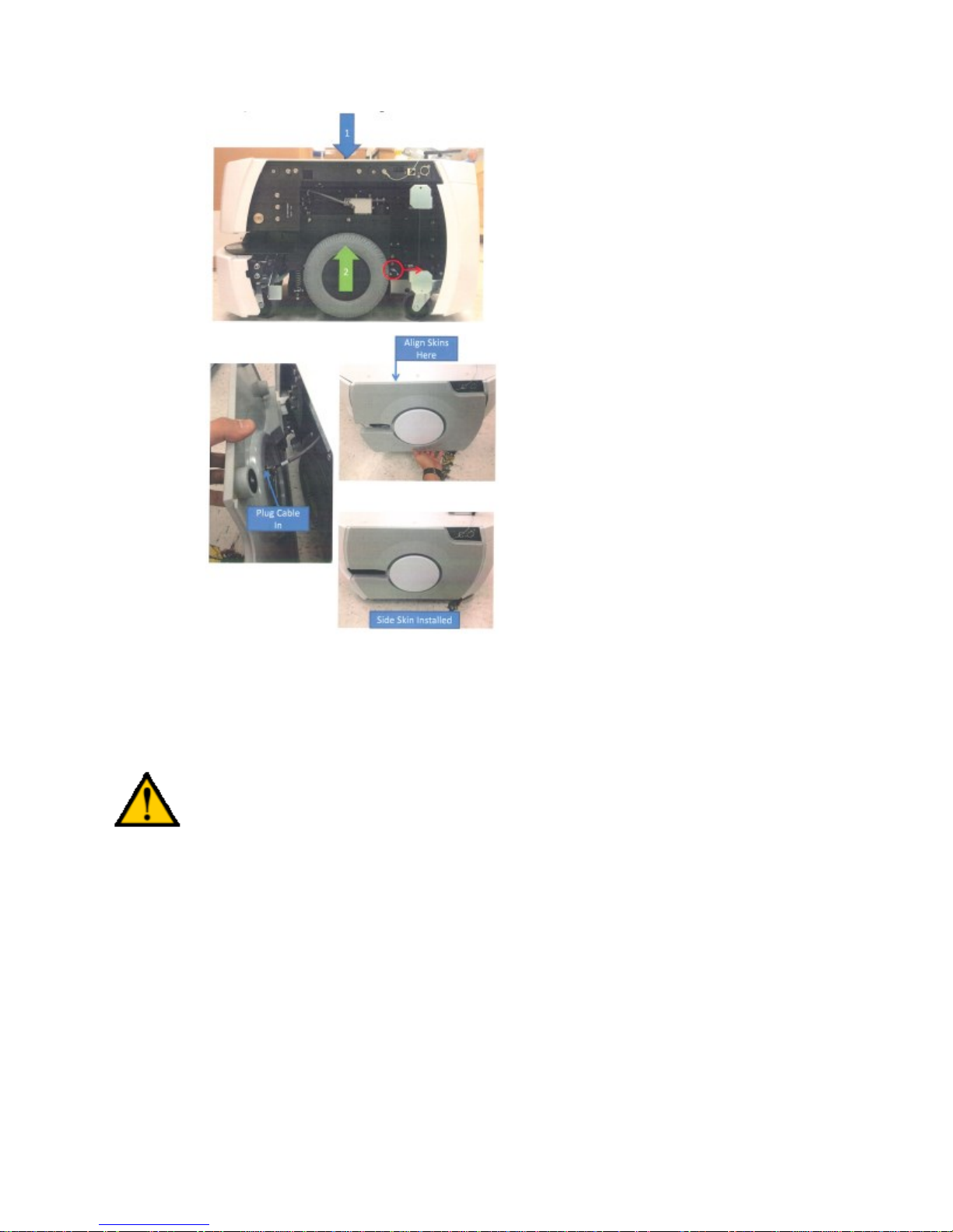
Table of Contents
CAUTION: You can damage the platform if you lift it incorrectly.
To move the robot, install the battery (see below), power on, and use the brake release button or joystick
drive mode.
Lifting the Platform
Use two people to lift the platform out of its crate.
Lift ONLY at the points shown.
Front Lifting Points
Lift on each side of the laser, under the upper side of the laser slot.
Do not lift at the center, where the laser is located. There is no frame support there.
Lift the metal frame behind the plastic body panels, not the plastic body panel.
Do not lift anywhere else! Refer to the following figure:
Page 27 of 134
Page 28
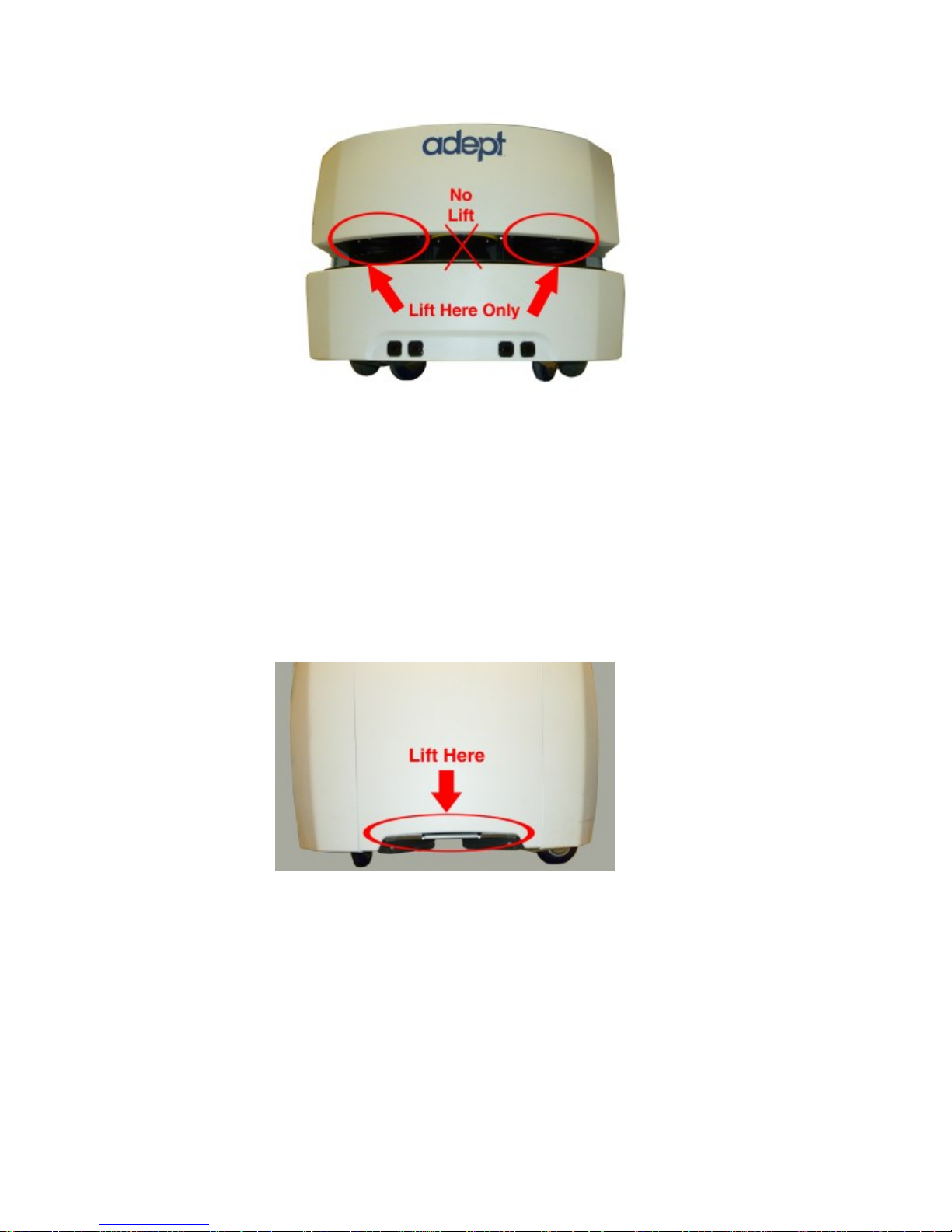
Table of Contents
Upper Side of Laser Slot, at Sides, NOT at Center
Rear Lifting Points
Lift near the center of the platform, where the cover has a raised section.
Do not lift anywhere else.
Lift the metal frame behind the plastic body panels, not the plastic body panel.
Refer to the following figures:
Page 28 of 134
Page 29
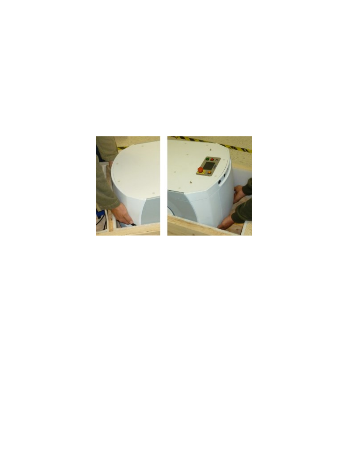
Table of Contents
Bottom of Inner Rear Cover. Lift from the Frame, not the Cover.
Repacking for Relocation
If the platform or other equipment needs to be relocated, reverse the steps in the installation procedures
in this chapter. Reuse the original packing crate and materials and follow all safety notes used for
installation. Improper packaging for shipment will void your warranty.
The platform must always be shipped in an upright orientation.
Installing a Pioneer LX System
Installing the Battery
Your Pioneer LX comes fully-assembled, but with battery packed separately.
NOTE: The battery is partially discharged for shipping. To fully charge the battery, refer to the
section on charging. Air shipping regulations require that the battery be shipped separately,
partially discharged.
Refer to Removing and Installing Covers in the Maintenance section for cover removal and installation.
1. Remove the inner rear platform cover.
2. Unlatch and open the battery compartment door, at the back of the platform.
The battery compartment door is capable of being locked. You may need to unlock it.
3. Lift and slide the new battery into the platform body.
The battery weighs 20 kg (44 lbs).
There are recesses at the front and the back of the battery, to aid in lifting it.
Page 29 of 134
Page 30
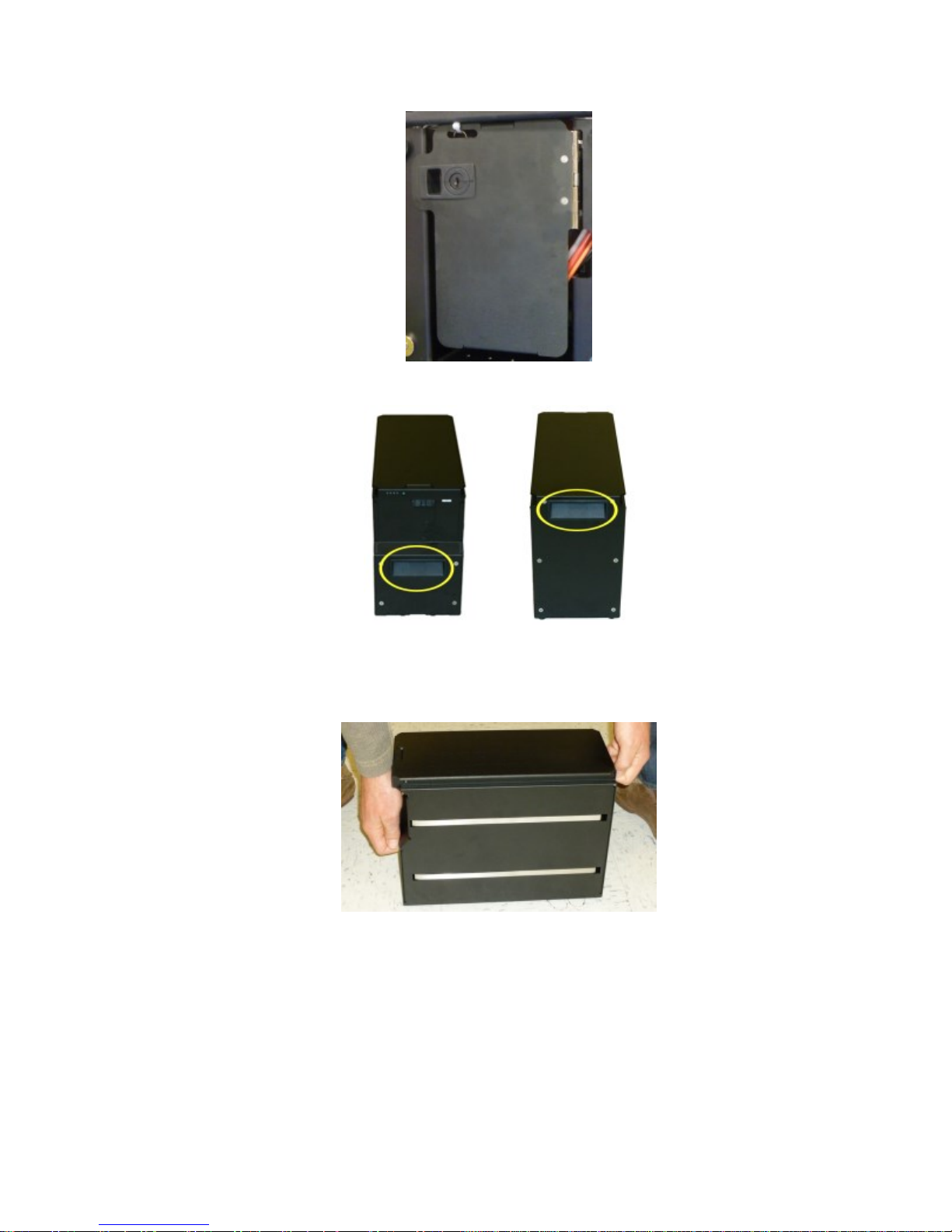
Table of Contents
Battery Compartment Door (keys are zip-tied for shipping)
Battery Recesses, for Gripping
The battery is designed to be lifted and replaced by one person, using one hand in each of the
grips, as shown in the following figure.
Lifting the Battery
The connectors for power and data go toward the rear of the platform.
4. Attach the battery power and data cables to the connectors at the rear of the battery.
5. Close the battery compartment door to secure the battery in place.
The battery compartment is designed to hold the battery tightly, so that it will not move within the
compartment, once the door is closed.
6. Reinstall the inner rear platform cover.
Page 30 of 134
Page 31

Table of Contents
CAUTION: It is very important that the charging station be mounted with one of these
methods, or the platform will simply move the charging station when it tries to dock,
rather than docking successfully.
Attaching Optional Accessories
You may need to attach any accessories that were shipped separately or detached for safety. Refer to
supplemental documentation for information on attaching those accessories.
Installing the Charging Station
The automated charging station (dock) can be used for either manual or automated charging of your
platform's battery.
The charging station sits on the floor. It can be attached to a wall with the wall bracket, attached directly
to the floor with screws through its base, or can sit stand-alone on the floor with the floor plate, all of
which will keep the charging station from moving when the platform docks. Both the wall bracket and
floor plate are included with each charging station.
For all mounting methods:
The top of the charging station foot is spring-loaded, and lifts off of the bottom of the foot slightly
to accommodate variations in the floor surface. The weight of the Pioneer LX will push the top of
the foot down.
Requirements
100 to 240 VAC, 50 to 60 Hz, 8 A (source voltage automatically detected)
Ambient operating temperature: 5° to 40° C (41° to 104° F)
5 to 95% humidity, non-condensing
Locate the charging station near an AC outlet with 1 - 2 meters (3.25 - 6.5 ft) of clear space in front.
Wall Bracket Mount
Attach the charging station mounting bracket to a wall, with the bottom edge of the bracket 98 ± 20 mm
(3.8 ± 0.8 in.) above the floor, using user-supplied anchors and screws.
Refer to the following figures:
Page 31 of 134
Page 32

Table of Contents
Charging Station, Wall Mount
2. Screw the two shoulder bolts, each with a washer, into the rear of the charging station. The
shoulder bolts are M5 x 4, stainless steel. Their locations are shown in the following figure. Tighten
to 9 N-m (80 in-lb).
Rear View of Charging Station and Wall Bracket
Page 32 of 134
Page 33

Table of Contents
Example of Charging Station Wall Mount Bracket Installation
3. Lower the charging station down, so the two bolts on the back of the charging station slide into the
bracket, to secure the charging station to the wall.
Floor-mount, without Floor Plate
Screw the base of the charging station directly to the floor, using three user-supplied screws. For dimensions of the
available holes in the base, refer to figure. We recommend M5 self-tapping or M4 sheet rock screws for this.
Floor-mount, with Floor Plate
This mounting method uses the floor plate. The floor plate is not shipped attached to the charging station, so you
must attach it for this type of mount. It will be in the crate with the platform, right behind the charging station.
Attaching the Floor Plate
Refer to the following figures.
1. Tip the charging station onto its back, so you can access the underside.
2. Remove the two lowest screws (M4 x 12 flat-head), if present.
In the following figure, these screws are circled. The location of the third screw hole is also circled.
3. Attach the floor plate to the base of the charging station with three M4 x 12 flat-head stainless steel
screws.
The floor plate comes with three screws, so you will have two spares.
The charging station and floor plate do not need to be attached to the floor, as the weight of the robot on the floor
plate will keep the charging station from moving.
Page 33 of 134
Page 34

Table of Contents
Underside of Charging Station Foot, Showing Screw Locations
NOTE: These are the three locations for the M4 x 12 flat-head screws. Two are already in place,
and need to be removed before attaching the plate.
Charging Station, Mounted on Floor Plate
Charging Station Floor Plate Dimensions
Page 34 of 134
Page 35

Table of Contents
All mounting methods
Install the power cord and turn the power switch to ON. The power switch is next to the power plug. The
blue power LED indicator should light.
Charging Station Contact Adjustment
The contacts on the charging station have five height settings. The station is shipped with the height in
the middle setting, which should be correct in most cases.
NOTE: Squeeze and keep the platform foot against the bottom of the foot to make this adjustment
easier.
Adjust the height of the contacts by using the pull-knob on the bottom of the dock. The height changes by
4 mm (0.15 in.) for each notch. See the following figure.
The height of the contacts should be set so that the roller is high enough to stay in contact with the
platform as it is docking, but low enough so that the bi-level of the roller guides the paddle under the
platform.
Charging Station Contact Adjusting Pull-Knob, Underneath bottom of station.
Embedded Computer Setup
Logging In
The embedded computer may be accessed by attaching keyboard, mouse and monitor, or by remote
connection over the network.
If the onboard computer is running Linux, you can select text-only mode or GUI/graphical desktop mode
on the console at boot.
If the onboard computer is running Linux, you can log in as guest (normal unprivileged user) or root
(privileged administrative account).
Passwords are changed in Linux using the passwd command.
New users can be added (and guest removed or disabled if desired) using the adduser command or the
“Users and Groups” utility in the “Administration” section of the “System” menu.
Page 35 of 134
Page 36

Table of Contents
Wireless Network Interface
(wlan0)
ESSID: "Wireless Network"
Static Address
Address: 10.0.126.32
Netmask: 255.255.255.0
External Ethernet Connection
("Maintainence LAN", eth1)
Static Address
Address: 10.0.125.32
Netmask: 255.255.255.0
Internal Device/Accessory Ethernet
Connection
("USER LAN", eth0)
Static Address
Address: 192.168.0.32
Netmask: 255.255.255.0
This subnet matches the default configuration of Axis ethernet
cameras, SICK LMS-100 laser rangefinders, and some other ethernet
devices. When connecting ethernet device(s) or user-supplied
computer(s) to this ethernet interface, configure its static IP settings
to match this subnet, or reconfigure this interface on the Pioneer
LX embedded computer to match your added device(s) or
computer(s).
The default password for the guest and root users on Linux, and the Administrator account on Windows,
is mobilerobots.
We recommend changing these default passwords..
Remote Access
If the onboard computer is running Linux, a remote login connection can be made using ssh (Secure
Shell). Files may be copied using sftp (Secure FTP) or scp (Secure Copy). To establish an ssh connection
from Windows to the onboard Linux computer, use the Putty application. To establish an ssh connection
from Mac OSX to the onboard Linux computer, run ssh from the Terminal. To establish an sftp/scp
connection from Windows to the onboard Linux computer, use the WinSCP application.
If the onboard computer is running Windows, a remote connection can be made using Remote Desktop.
Networking
The computer's network interfaces have been configured with the following default settings:
(See also http://support.mobilerobots.com/wiki/Default_Network_Configuration)
You may need to change the settings of the wireless network interface and external ethernet connection to
match your existing network. Consult with your institution IT department or network maintainer for
details on specific settings required for your network.
Configuring Linux Network Settings
You may configure wireless and wired network settings by starting graphical/desktop mode (see above),
opening the System Settings tool from the launcher panel, and opening Network.
Page 36 of 134
Page 37

Table of Contents
See http://support.mobilerobots.com/wiki/Linux_Network_Configuration for more information on
configuring Linux network settings.
Configuring Windows Network Settings
To change network settings in Windows, open Contol Panel from the Start menu. Open the Network or
Network and Sharing Center control panel, and choose Change adapter settings.
See http://support.mobilerobots.com/wiki/Windows_Network_Configuration for more information on
configuring Windows network settings.
Page 37 of 134
Page 38

Table of Contents
Chapter 3: Software Demonstrations and
Quick Start
This section will walk you through running some example programs from ARIA and MOGS.
You can run these examples either on the robot embedded computer, or, you can simulate the robot on
your own laptop or desktop workstation, by first simply running the MobileSim simulator and selecting
the pioneer-lx robot type (however, not all hardware features and devices are simulated.)
ARIA Demo
ARIA includes an example called demo. This is as simple text mode program that connects to the robot
and other devices and displays information read from them. You may also drive (teleoperate) the robot
using the keyboard, test movement of a pan/tilt camera, etc.
Onboard Computer Running Linux:
1. If using simulation, install MobileSim and ARIA from the CD or from
http://support.mobilerobots.com/wiki/Software. Run MobileSim and select the “pioneer-lx” or
“pioneer-lx-ld” robot type.
2. If using the actual robot, log in to the onboard computer using ssh, or log in at the console and
start a terminal session. Log in as guest with password mobilerobots.
3. Change to the ARIA examples directory with the following command:
cd /usr/local/Aria/examples
4. Run demo with the following command:
./demo
Onboard Computer Running Windows:
1. If using simulation, install MobileSim and ARIA from the CD or from
http://support.mobilerobots.com/wiki/Software. Run MobileSim and select the “pioneer-lx” robot
type.
2. If using the actual robot, log in to the onboard computer using Remote Desktop, or log in at the
console. Log in as Administrator with password mobilerobots.
3. Double click the ARIA Demo icon on the desktop to run ARIA Demo, or run it from the Start
menu (All Programs -> MobileRobots -> ARIA -> demo).
4. Or, to run it from a command prompt:
1. Open a command prompt (Start->All Programs->Accessories->Command Prompt)
2. Change to the ARIA programs directory with the following command: cd “\Program
Files\MobileRobots\ARIA\bin”
3. Run demo with the following command: .\demo.exe
Page 38 of 134
Page 39

Table of Contents
Demo will connect to the robot, displaying information about the connection and the robot such as Name
and Subtype.
Demo starts in teleoperation/drive mode. Use the arrow keys or robot joystick to drive the robot. Use the
space bar to stop.
Ensure there is adequate clearance (at least 5 meters) on all sides of the robot before driving. The robot
can move fast!
The robot's E-Stop button must be released, and motors enabled (E key) before driving.
Use other keys on the keyboard to switch to different modes. Press ? for a list of modes. For example,
laser mode (L key) connects to the laser and displays information read from it. Direct command mode (D
key) lets you send individual commands directly to the robot controller (See See Communication Packet
Protocol on page 117 for list of commands).
Press Control-C or Escape to exit.
ARNL Demo Server and MobileEyes
ARNL includes an example server which can be used with the MobileEyes remote graphical user
interface to observe and control the robot. You can use the source code of the example server to integrate
ARNL into your own software.
To use MobileEyes on your laptop or other computer, download and install MobileEyes from the CD or
from http://support.mobilerobots.com/wiki/MobileEyes.
Onboard Computer Running Linux:
1. If using simulation, install MobileSim and ARIA from the CD or
http://support.mobilerobots.com/wiki/Software. Run MobileSim and select the “pioneer-lx” robot
type.
2. If using the robot, log in to the onboard computer using ssh, or log in at the console and start a
terminal session. Log in as guest with password mobilerobots.
3. Change to the Arnl examples directory with the following command:
cd /usr/local/Arnl/examples
4. Run arnlServer with the following command:
./arnlServer
Onboard Computer Running Windows:
1. If using simulation, install MobileSim and ARIA from the CD or from
http://support.mobilerobots.com/wiki/Software. Run MobileSim and select the “pioneer-lx” robot
type.
2. If using the actual robot, log in to the onboard computer using Remote Desktop, or log in at the
console. Log in as Administrator with password mobilerobots.
Page 39 of 134
Page 40

Table of Contents
3. Double click the arnlServer icon on the desktop to run arnlServer, or run it from the Start menu
(All Programs -> MobileRobots -> ARNL-> arnlServer).
4. Or, to run it from a command prompt:
1. Open a command prompt (Start->All Programs->Accessories->Command Prompt)
2. Change to the ARNL programs directory with the following command: cd “\Program
Files\MobileRobots\ARNL\bin”
3. Run demo with the following command: .\arnlServer.exe
The server will connect to the robot and other devices, displaying information about the connection and
the robot such as Name and Subtype. When it finishes connecting to the robot, laser, and other
configured devices, it will indicate that it has opened a server port for remote connections.
5. Next, run MobileEyes on your laptop.
6. For Robot Server, enter the address of the onboard computer, e.g. 10.0.125.32 (no user name or
password are necessary, leave these fields empty) and click Connect.
MobileEyes will connect to the server. The robot is represented as a red oval. Readings from the laser
rangefinder are represented by dots. Data about the robot (position, velocity, debugging information) are
displayed in the Details windows, to open these enable Details and Custom Details in the View menu.
Battery level and other indicators are shown in the status bar at the bottom of the MobileEyes window.
To navigate autonomously, the robot requires a map, and initialization of ARNL. Refer to the ARNL
introduction for mapping instructions: http://support.mobilerobots.com/docs/all_docs/ARNL-
introduction.pdf
Quick reference instructions on creating maps for ARNL is available in the ARNL docs directory
(Mapping.txt).
Once a map is loaded into arnlServer, use the Localize to Point button in MobileEyes to manually
perform the initial localization. Once localized, ARNL is ready to navigate autonomously to goals and
points.
Before ARNL is initialized, it is in a “Lost” state. When lost, you cannot drive the robot in Safe Drive
Mode. To disable unsafe drive mode, click the Safe Drive button in the toolbar in MobileEyes. You can
then use the drive controls in MobileEyes to drive the robot, however, no checking for collisions using the
laser rangefinder is performed when in unsafe drive mode!
WARNING: NO COLLISION DETECTION is performed using sensing when in Unsafe drive mode.
Ensure there is adequate clearance (at least 5 meters) on all sides of the robot before driving. The robot
moves fast!
The robot's E-Stop button must be released and motors enabled before it can drive.
Press Control-C to exit from arnlServer.
Note, if the remote connection to the robot is closed, then arnlServer will automatically quit as well. For
information about running arnlServer or other programs in the background, rather than attached to a
remote connection terminal in Linux, see
http://support.mobilerobots.com/wiki/Running_A_Linux_Program_In_The_Background.
Page 40 of 134
Page 41

Table of Contents
Slope
up to 1:12
Step
traversal
up to 15 mm (0.6 in.)
Gap
traversal
up to 15 mm (0.6 in.)
Tempera
ture
5° to 40° C (41° to 104° F)
Humidit
y
5 to 95%, non-condensing
Chapter 4: Components and Operation
Note, before proceeding, you need to have performed the steps covered in the Setup and Getting Started
chapters.
Operating Environment
The Pioneer LX is designed to operate in an environment that is wheelchair accessible. Care must be
taken to avoid:
glass doors and walls
pits or edges without a curb, railings or low bumpers
floors with access panels removed
loose cables, hoses, etc.
large, highly-reflective objects
Floors must provide good traction, typical of good walking conditions.
Page 41 of 134
Page 42

Table of Contents
The Pioneer LX is not intended for use in hazardous environments (explosive gas, water, dust, oil mist). It
has an IP rating of IP-40.
Typical Operation
During normal startup, Pioneer LX powers on all its onboard systems, including its embedded computer.
The computer system may be optionally configured to run example or user-created software at startup
(See http://support.mobilerobots.com/wiki/Running_a_Program_at_Linux_Startup), otherwise you may
log in remotely or by attaching keyboard, mouse and display.
See Setup on page 24 for more information on configuring the computer system.
See See Programming on page 51 for more information on writing software using the included Pioneer
SDK and ARNL navigation libraries.
See See Software Demonstrations and Quick Start on page 38 and the separate guide Getting Started
with ARNL Laser Navigation for information on running the ARNL laser navigation servers and using
them for autonomous operation of the robot.
Startup and Shutdown
Press and hold the power ON button, then release. It takes about a minute for the robot and computer to
start.
To turn the system off, press and hold the OFF button. It is recommended that you shut down the
computer operating system first if possible. On Linux, use the Shutdown command in the system menu,
or the shutdown -h now command as root. On Windows, use the Shutdown command in the Start
menu.
To reboot the system (including onboard computer), power the system off using the OFF button, then
start it using the ON button.
Note: The Pioneer LX is always powered on when attached to the charging station, and will not turn off if the
OFF button is pressed. To power off the Pioneer LX, hold the BRAKE RELEASE button and carefully move it off the
charging station.
Power and Charging
The robot's battery module supplies power for all robot components including the motors, electronics,
and accessories.
The battery ships separately from the platform The battery is shipped fully-charged. The battery is sealed.
For instructions on installing and removing the battery module, See Setup on page 24.
Battery recharging is performed by placing the robot in its "dock" or recharging station. Battery charging
is completely managed by the platform. All onboard systems function continuously while the battery
recharges.
Run-time, with no load, is approximately 13 hours. This will vary depending on use and accessory power
consumption.
Page 42 of 134
Page 43

Table of Contents
LED
Color
Meaning
1
Red
Error condition
Green
25% state of charge
2
Green
50% state of charge
3
Green
75% state of charge
4
Green
100% state of
charge
Recharge time is approximately 3.5 hours.
The robot's motors will be automatically disabled while on the charging station.
Battery Indicators and Controls
The battery module has one push-button and four LEDs. From left to right, they indicate:
Battery LEDs, Push-Button, Power Cable, and Data Cable
The push-button "wakes up" the battery, so it displays its state of charge. This can be useful when a
battery is in storage, and you need to know its state of charge.
Charging Station
The charging station, or "dock", is both a manual and an automated means for recharging your Pioneer
LX.
During autonomous operation using ARNL, if Auto Dock is enabled (via
MobileEyes and "Auto Dock" configuration parameter), the robot can
automatically recharge itself when idle or if at a low state of charge, using the
charging station. The robot will navigate to a special Dock indicator object in
the map (place this Dock point approximately 1-2 meters away from the
charging station in the map, pointing towards it), use the laser rangefinder to
Page 43 of 134
Page 44

Table of Contents
detect the shape of the charging station, and then turn around and back onto the charging station to
charge.
Note, there may be up to a 10-second delay between when a robot docks and when the charging LED
turns on. If the robot is fully charged, the Charging LED will also turn off.
If the robot is powered off, it will turn on automatically when it is pushed onto the charging station. The
platform cannot be turned off while on the charging station.
The robot's motors will be automatically disabled while on the charging station.
It is recomended that the robot be left charging on the docking station to charge when not in use, and that
it regularly be left docked to fully recharge.
Indicators, Controls, and Connections
The charging station has a power switch and two LEDs:
blue indicates that power is available.
yellow indicates that a charge is in progress.
The power plug for AC supply is on the right side of the station, as viewed from the front. Power
requirements are 100 - 240 VAC, 50 - 60 Hz, and 8 A.
The plug for connecting the manual charging cable is on the left side of the station, as viewed from the
front.
Environmental Requirements
Ambient temperature range: 5° to 40° C (41° to 104° F)
Humidity: 5 to 95% non-condensing
Maintenance
The charging station contacts should be cleaned quarterly with isopropyl alcohol. See Charging Station
Contacts on page 90.
The guide roller can be replaced in the field. See Charging Station Roller and Bearing on page 99.
Contact/Foot Height Adujstment
If necessary, the height of the charging station contacts can be adjusted. See Charging Station Contact
Adjustment on page 35.
Manually Charging the Battery
Inside the Platform
To manually place the platform on the dock for recharging, first engange the E-STOP button. While
holding the Brake Release button down, slowly push the robot backwards, so that the rear of the platform
slides over the contacts of the charging station.
NOTE: You will need to press and hold the brake release button while pushing the robot.
Page 44 of 134
Page 45

Table of Contents
Outside the Platform
A battery can be manually charged outside of the platform, by using the connector on the left side of the
charging station with the provided charging cable. This method may be used for charging a spare battery,
while the second battery is still in the platform, and the platform is in use.
There is up to a 10-second delay between when you connect the battery cable and when the charging LED
turns on.
NOTE: The charging station cannot charge a platform and a separate battery at the same time. If a
platform is at the station, the power to the manual charge connector is cut off.
Balancing the Battery
The battery is composed of multiple cells, which need to stay balanced in order to maintain maximum
run-time. By default, the battery will be automatically balanced after a full charge cycle; leave the robot
charging on the docking station until fully charged and the Charge light turns off. If using multiple
batteries or otherwise charging the battery outside the robot, leave it plugged into the charging station
until fully charged and balanced. A battery should be left to charge fully and balance weekly, or more
frequently.
In general, it is recommended to leave the robot engaged in the charging station whenever not in use,
rather than turning the robot off.
Operator Control Panel
The Operator control panel comprises a touch-screen, an E-Stop button, ON and OFF buttons, a brakerelease button, and a keyswitch.
The operator panel is located on the top plate at the rear of the robot. It may be removed from the top
plate and repositioned if a customized payload is added.
ON Button
The ON button is used for restoring power after the OFF button has been pressed, and the software has
finished shutting down the robot.
It can also be used to restore power after an E-Stop has been pressed.
OFF Button
The red OFF button removes power from all systems except the charging hardware circuits. The
platform's software systems prevent loss of data on shutdown, and save the platform’s last known
location so it automatically localizes when it is next powered on.
NOTE: The OFF button can be disabled by the keyswitch, which can be locked.
Page 45 of 134
Page 46

Table of Contents
Mo
de
Description
light discs
Light Tower Outputs
on
1
"Busy". Blue arcs rotate back and forth.
OUT1 (green), OUT2
(orange), OUT3 in turn.
2
"Error/EStop". Flashing red.
OUT3 (red) periodic.
3
"Warning". Flashing yellow.
OUT2 (orange) periodic.
E-Stop Button
When pressed, the red, latching push-button removes power from the platform’s motors and from the EStop-controlled power port after a 1 second delay. To reset the E-Stop, twist the button slightly, so it pops
up.
When the E-Stop button is pressed, the robot's motors will be disabled, and must be re-enabled by
software (using the ENABLE command). Motor enabled/disabled state is available through ARIA. The
ARIA and ARNL example programs show how to detect whether motors are disabled, whether the EStop button was pressed, and how to re-enable the motors.
Brake-release Button
Hold down the brake-release button to manually move the platform.
Keyswitch
The keyswitch can be used to disable the OFF button and certain functions on the Operator screen. The
key can be removed in either the locked or unlocked positions.
Other Controls and Indicators
Light Discs, Light Tower
Circular lights on the sides of the platform are used by software to indicate status or state. A usersupplied light tower can also be added for extra signaling.
Several modes are available with different colors and patterns displayed on the light discs and light
tower. Software can set a mode using the WHEEL_LIGHT command (See Programming and Protocol).
ARIA and ARNL contain example programs that show how to send the wheel light command to set
different modes.
Page 46 of 134
Page 47

Table of Contents
Mo
de
Description
light discs
Light Tower Outputs
on
4
"Motion+Caution". Blue arcs rotate, rest of disc
flashing orange.
OUT1(green) periodic.
OUT2 (orange) periodic
alternating with OUT1.
OUT4 (buzzer) periodic
with OUT1.
5
"Busy+Caution". Orange arcs rotate back and forth.
OUT2 (orange) periodic.
6
"Progress/Clock". Green arcs rotate over a given
percentage of the disc (0%, 25%, 50%, 75% or
100%)
none
7
"Warning Motion". Orange arcs rotate.
OUT1 (green) and OUT2
(orange) alternate.
OUT4 (buzzer) periodic
with OUT1.
8
"Motion+Turn Signal". Blue arcs rotate, orange
segment flashes on right or left side.
OUT1 (green) periodic.
OUT4 (buzzer) periodic.
9
"Motion". Blue arcs rotate.
OUT1 (green) periodic.
OUT4 (buzzer) periodic.
10
"Ready". Pulse blue slowly (0.25 Hz).
OUT1 (green) on.
Joystick
The joystick plugs into the left side of the Pioneer LX, under the small access panel at the upper-right
corner of the platform.
It may be used with running software (such as ARIA demo or ARNL arnlServer) to manually drive the
robot. (For example, when creating a map for ARNL.)
Page 47 of 134
Page 48

Table of Contents
WARNING: The Pioneer LX may not sense obstacles while manually operated with the
joystick, unless running software does so..
•
LOGIC
•
20V PWR
•
ETH1 • PC • 12V PWR
•
ETH2
•
ESTOP
•
5V PWR
•
WLAN
•
DRIVE • VBATT
•
DISK
Indicator
Meaning
LOGIC
The robot controller has power
Original joystick (left), New joystick (right)
Hold down the joystick trigger (new, blue joysticks) or "Go" button (older, yellow joystick) to drive. Turn
the Speed control counter clockwise to reduce speed. Always start at a slow speed, and increase speed by
turning clockwise if desired.
NOTE: The Joystick handle should be facing you, not away from you.
The joystick’s GOAL button (secondary button) can be used to mark positions while making a map scan
for ARNL, or its state can be detected for any purpose by your own custom software.
MTX-Lynx Core Diagnostic Indicators
The left end of the Core has 12 indicator lights. The following table gives their meanings:
Page 48 of 134
Page 49

Table of Contents
Indicator
Meaning
PC
The computer and the robot controller are communicating
DRIVE
The motors are enabled and the drive wheels are under servo control
ESTOP
E-Stop button engaged
20V
20 V power is available
12V
12 V power is available
5V
5 V power is available
VBAT
Raw battery power is available
ETH1
The internal device ethernet ("USER LAN") interface is showing activity
ETH2
The external ethernet ("Maintenance Ethernet") interface is showing
activity
WLAN
The wireless ethernet interface is showing activity
DISK
The disk is showing activity
Sensors
Laser Rangefinders
The onboard SICK S300-Expert laser rangefinder is a very precise scanning sensor. The laser provides 500
readings in a 250 degree field of view, with a typical maximum range of 15 m (49.2 ft). The laser operates
in a single plane, positioned at about 191 mm (7.5 in.) above the floor. In most environments, the sensor
will provide highly-accurate data.
Glass, mirrors, and other highly-reflective objects cannot be reliably detected by the laser. Caution must
be exercised when operating the platform in areas that have these types of objects. If the platform will
need to drive in close proximity of these objects, we recommend that you use a combination of markings
on the objects, such as tape or painted strips, and also use forbidden sectors in the map, so that the
platform knows to plan paths safely around these objects.
Page 49 of 134
Page 50

Table of Contents
The SICK S300 can be configured to trigger robot stop signals based on obstacle zone detection. This is
normally disabled. Configuration software tools are available from SICK for modifying laser
configuration.
ARNL will use this laser as its primary sensor. Software can also use ARIA to obtain sensed obstacle data
from the laser.
LD-series Pioneer LX robots also include a SICK TiM 510 laser rangefinder mounted closer to the floor to
help detect smaller objects as well. (AUX sensor C.) Connectors are provided for up to two additional
SICK TiM 510 laser rangefinders as well (AUX sensors A and B).
Sonar
Lynx-based Pioneer LX robots include two short-range ultrasonic sensors (sonar) for extra sensing near
the floor in front of the robot. These were removed for the LD-series robots; they are replaced by a small
laser rangefinder.
All Pioneer LX robots include two rear short-range ultrasonic (sonar) sensors on the rear. Note that with
only these rear short-range sonar sensors, rear sensing is limited. Most operation of the robot should be
forward motion and rotation only.
Bumper
One bumper panel, with two pairs of sensors, is mounted at the front of the platform, should the obstacleavoidance systems fail to detect an obstacle. The Pioneer LX indicates a left bumper hit (0) to software if
only the left side of the bumper panel is triggered, a middle bumper hit (1) if both sides of the bumper
panel are triggered, and a right bumper hit (2) if the right side is triggered.
Aditional user-supplied bumper switches can be added using the User Bumper connector on the rear
upper core, in the payload bay.
Internal Sensors
Encoders and Gyroscope
Each wheel has an encoder that tells the robot controller how far the wheel has turned, and in which
direction. Each wheel also has a Hall sensor. The core contains a gyroscopic sensor as well, to measure
rotation.
The robot's controller uses these internal sensors for feedback as it maintains requested velocities, and
when it estimates robot position and velocity, which are provided to the software. Raw encoder and gyro
data are not available to user software.
Page 50 of 134
Page 51

Table of Contents
Computer
Software with ARIA Library
TRANSLATIONAL VELOCITY,
ROTATIONAL VELOCITY,
Other Commands…
Robot Controller
MARCOS firmware
Laser
Rangefinder
Wireless Network
802.11 wifi
Joystick
Battery
Monitor
LCD
Ethernet
LAN
POSITION (X,Y,Θ)
Other status…
Motors, Encoders
Gyro
Other
devices…
Robot
Command
Protocol
MTX IO
MTX
Sonar
Chapter 5: Programming
All Pioneer 2/3-compatible platforms use a two-tier architecture. Pioneer LX’s microcontroller with
embedded MARC firmware manages all the details of the robot’s mobility and internal systems including
implementing velocity control of the robot platform, coordinating the motors, receiving encoder data,
integrating encoder and gyro data to determine an estimate for robot position, managing power to all
components, and more. MARC unifies the mobile robot base into a single system with one interface
channel through which software on the onboard computer can communicate and control the mobile robot
base Software running on the onboard PCs communicates with MARC to receive data and send
commands.
ARIA
Software communicates with MARC via a simple packet-based protocol (See Communication Packet
Protocol on page 117) via a serial connection between the robot and the embedded computer.
To support development of software, a C++ development library is provided called ARIA which
implements this protocol, provides interfaces to many accessory devices, and also includes many useful
tools for robotics and cross-platform programming. It is also possible to use ARIA in Python and Java via
wrapper libraries and Matlab via a MEX/C interface layer. ARIA installation packages can be found on
the CD or USB stick included with your robot, preinstalled on the onboard computer, and at
http://support.mobilerobots.com/wiki/ARIA. Future updates are availbale at this website as well. ARIA
can be used on Linux with the standard GNU C++ compiler and linker (g++), or on Windows with
Microsoft Visual C++. ARIA is provided as open-source software, under the terms of the GNU General
Public License (GPL). Full reference documentation is included. For more information about system
Page 51 of 134
Page 52

Table of Contents
requirements and compilers, see the ARIA README.txt file. For details of the license, see the
ARIA LICENSE.txt file. For full reference documentation, see Aria-Reference.html or the contents of
ARIA's doc directory.
In addition to the ARIA library, MobileRobots provides additional development libraries, including the
ArNetworking framework for network programming over TCP and UDP, and the ARNL intelligent
navigation library. Useful tools for robot development also include the MobileSim simulator, the
MobileEyes user interface application, and the Mapper3 map editing tool. This software can be found on
the CD provided with the robot, and at http://support.mobilerobots.com/wiki/Software.
ARIA automatically handles all communication with the robot components and many accessory devices,
including but not limited to the laser rangefinder, the robot’s sonar and bumper sensors, LCD display,
pan/tilt cameras and pan/tilt units, and more. To communicate with the robot, ARIA sends and receives
messages with the robot’s embedded firmware. When using ARIA or other development software,
however, you do not need to implement this protocol directly. (See Communication Packet Protocol on
page 117 for a description of this protocol.)
Robots in Motion
When Pioneer LX receives a motion command, it accelerates or decelerates the robot according to
acceleration or deceleration parameters previously set until the platform either achieves the requested
speed (for velocity commands) or nears the requested movement distance (when performing MOVE,
HEAD and DHEAD commands). Rotation headings and translation setpoints are achieved by a
trapezoidal velocity function, which MARC recomputes based on motion commands received.
MARC automatically limits velocities, acceleration and deceleration to client-modifiable limits and
ultimately by absolute limits. These limits take effect on subsequent commands, not on the current
translation or rotation activity, and are reset when the client disconnects or the robot system is reset.
The orientation position commands (setHeading(), setDeltaHeading()) turn the robot with respect to its
internal dead-reckoned angle to an absolute heading (0-359 degrees), relative to its immediate heading, or
relative to its current heading setpoint (achieved or last commanded heading), respectively.
The STOP command is equivalent to requesting both translation and rotation velocities of 0; the robot
will decelerate to 0. The E-STOP command #55 overrides normal deceleration and abruptly stops the
robot in the shortest distance and time possible. Accordingly, the robot brakes to zero translational and
Page 52 of 134
Page 53

Table of Contents
rotational velocities with very high deceleration and remains stopped until it receives a subsequent
translation or rotation velocity command from the client.
Position Integration
Pioneer platforms track their position and orientation based on wheel motion sensed by encoder readings
and from the integrated gyroscope.
On start-up, the robot position is initialized to (X=0mm,
Y=0mm, θ=0°), pointing along the positive X-axis at 0 degrees.
As the robot moves, the position is updated with reference to
this initial coordinate frame, and the latest calculated position
estimate is reported in the standard SIP data packet (see
below) as XPos, YPos and Theta. X and Y coordinates are
provided in millimeters. θ varies between -179 to 180 degrees.
ARIA uses these position estimates to update its own stored
position, which may optionally have transformations
automatically applied to place the robot in any coordinate
system, or to make corrections.
Be aware that registration between external and internal coordinates deteriorates rapidly with movement
due to gearbox play, movement in robot suspension, wheel imbalance, wheel slip, accumulated small
errors in encoder sensing, and many other real-world factors. You can rely on the dead-reckoning ability
of the robot for a short range—on the order of several meters and one or two revolutions, depending on
the surface. (ARNL addresses this problem by using additional sensing and sophisticated localization
algorithms to correct the position of the robot with respect to features within a known and mapped
environment.)
You may translate and rotate the robot into a new coordinate system in ARIA using the
ArRobot::moveTo() function. All subsequent position updates received by ARIA from the robot will
then continue to use that coordinate system to reflect movement of the robot.
Device Interfaces
The robot controller and and other devices are connected to the embedded computer via serial
connections through which commands can be sent and data received. These serial connections use
USB interfaces of the onboard computer (via FTDI USB-serial adapters).
ARIA has been preconfigured on the Pioneer LX embedded computer to connect to the robot controller
via the correct interface and using the correct baud rate as shown in the table below. On Linux, the
/etc/Aria.args file contains the following default connection options:
-robotPort /dev/ttyUSB0 -robotBaud 57600
On Windows, the ARIAARGS System environment variable contains the following default connection
options:
-robotPort COM3 -robotBaud 57600
Page 53 of 134
Page 54

Table of Contents
Component
Linux
Interface
Windows
Interface
Serial
Type
Baud Rate
Robot Controller (MARC)
/dev/ttyUSB0
COM3
RS-232
57600
Battery Data Monitor
/dev/ttyUSB1
COM4
RS-232
115200
Sonar Interface
/dev/ttyUSB2
COM5
RS-422
115200
Reserved (Sonar 2)
/dev/ttyUSB3
COM6
RS_422
-
Laser Rangefinder
/dev/ttyUSB4
COM7
RS-422
230400
LCD Panel
/dev/ttyUSB8
COM11
RS-422
115200
User/Accessory Serial Port 1 (RS-232
1)
/dev/ttyUSB9
COM12
RS-232
-
User/Accessory Serial Port 2 (RS-232
2)
/dev/ttyUSB10
COM13
RS-232
Aux Sensor A
/dev/ttyUSB5
COM8
RS-232
-
Aux Sensor B
/dev/ttyUSB6
COM9
RS-232
-
Aux Sensor C, low front secondary
laser on LD-series robots.
/dev/ttyUSB7
COM10
RS-232
115200 for
secondary laser
(SICK TiM 510) on
LD-series
EHCI USB Composite Device 6
Serial Port A
COM3
Any program using ArArgumentParser and ArRobotConnector will automatically use these
options, as well as any additional options given on the program command-line.
Once connected to the Pioneer LX robot controller, ArRobotConnector will next automatically connect
to the sonar, battery, and LCD (operator panel) using the correct interfaces as shown below. On Pioneer
LX, ArLaserConnector will, by default, connect to the laser rangefinder using the correct interface as
shown below.
Optional accessory devices ordered with the robot will be connected to the user serial, ethernet or
USB ports. Refer to the accessory device's supplementary documentation for information on how it is
connected to the onboard computer and ARIA. You may use the user serial ports, ethernet ports and
USB ports for user-added devices as well.
Note, /dev/ttyUSB11or COM14 will also be present but is not available for user devices.
Windows COM Port Assignment
Windows assigns COM port names based on unique USB device identifiers, so if you reinstall Windows
or remove and reinstall the FTDI drivers, default COM port names on an individual Pioneer LX robot will
be arbitrary and must be reassigned as follows. COM port names can be reassigned by clicking
Adanced... in the Port Settings tab of the serial device properties, acessible through the Device Manager
or Devices and Printers. There are three FTDI USB-serial converters, connected to the computer's sixth,
seventh and eightth USB interfaces, each providing four serial ports.
Page 54 of 134
Page 55

Table of Contents
Location: Port_#0006.Hub_#0000
(Loc56)
Serial Port B
COM4
Serial Port C
COM5
Serial Port D
COM6
EHCI USB Composite Device 7
Location: Port_#0007.Hub_#0000
(Loc57)
Serial Port A
COM7
Serial Port B
COM8
Serial Port C
COM9
Serial Port D
COM10
EHCI USB Composite Device 8
Location: Port_#0086.Hub_#0000
(Loc58)
Serial Port A
COM11
Serial Port B
COM12
Serial Port C
COM13
Serial Port D
COM14
Further Programming Information
For further information about programming with ARIA, read the ARIA README.txt file, LICENSE.txt
file, and the ARIA API Reference Documentation.
When ARIA is installed on Linux, the ARIA API Reference Documentation can be read by opening
/usr/local/Aria/Aria-Reference.html in a web browser.
When ARIA is installed on Windows, the ARIA API Reference Documentation can be read by opening
C:\Program Files\MobileRobots\Aria\Aria-Reference.html
Also look at the ARIA examples, installed in /usr/local/Aria/examples on Linux and C:\Program
Files\MobileRobots\Arnl\examples on Windows.
For further information about programming with the ARNL laser navigation and localization libraries,
read BaseArnl-README.txt, ARNL-README.txt file, LICENSE.txt file, and the BaseArnl
API Reference Documentation and Arnl API Reference Documentation.
When ARNL is installed on Linux, the API reference documentation can be read by opening
/usr/local/Arnl/doc/BaseArnl-Reference.html and /usr/local/Arnl/doc/ArnlReference.html in a web browser.
When ARNL is installed on Windows, the API reference documentation can be read by opening
C:\Program Files\MobileRobots\Arnl\doc\BaseArnl-Reference.html and C:\Program
Files\MobileRobots\Arnl\doc\Arnl-Reference.html.
The ArNetworking library, used for remote command and monitoring with ARIA and/or ARNL also
includes an API reference manual and example programs. ArNetworking is installed as a subdirectory of
the Aria directory.
Any additional libraries installed to support optional accessories will be found as subdirectories in the
Aria installation directory, and will contain their own documentation and examples.
For discussion and questions about programming with ARIA and ARNL, join the aria-users
discussion email forum. See the following link for more information
Page 55 of 134
Page 56

Table of Contents
http://support.mobilerobots.com/wiki/aria-users
Page 56 of 134
Page 57

Table of Contents
Chapter 6: Payloads
Everything that you attach to the Pioneer LX is referred to as the payload.
The Pioneer LX provides the mobility and navigation you will need, as well as power and I/O
connections between the platform and your payload, so the two can work effectively together.
Your payload may be added to the equipment mounting deck (see below), or you may replace the deck
and/or top plate with your payload. The Pioneer LX may be used with or without the top plate or deck or
both. The front portion of the top plate may be removed by removing the hinge from rear portion. The
rear portion may be removed by detaching the USB, serial and VGA ports, wifi antennas, and LCD panel.
(Note, the LCD panel with on/off buttons and e-stop must be connected to the LX core for the robot to
work, but it may be positioned anywhere on your robot or payload, such that the e-stop button is still
easily reached.)
Top plate/deck options. (Additional metal extrusion frame pieces in last figure not included with robot.)
Considerations
The main factors to consider in designing a payload are the size, weight, and center of gravity of the
payload, and power requirements. Adding weight to the Pioneer LX tends to have less effect on run-time
than adding electrical power requirements. Additional weight will have more effect on carpet than on
hard surfaces.
Weight
Increased payload weight will decrease your robot's run-time. This will be most noticeable if you are
driving the robot up an incline. On level ground, a certain amount of extra weight will not shorten the
robot's run-time very much. When adding a payload with substantial weight, the center of gravity of the
entire robot needs to be considered. This is particularly important if you intend to equip the Pioneer LX
with a robot arm, which would be lifting items off-center from the Pioneer LX.
Page 57 of 134
Page 58

Table of Contents
A heavy payload, with most of its weight concentrated just above the Pioneer LX, will be much more
stable than the same weight payload in which the weight is either off-center or high above the top of the
platform.
NOTE: The weight of your payload added to the weight of the parts it is carrying must not
exceed 60 kg (132 lb).
Power Consumption
Using devices on your payload that consume significant power will noticeably shorten the run-time of
the robot. You should try to minimize such power consumption whenever possible.
Examples of power-consuming payloads would be one with a robot arm attached, or any motorized
fixture as part of the payload. The standard Operator screen and light discs consume some power, but are
not significant compared to the rest of the platform.
The battery is rated at 1500 W*hr (1.5 kWh). Unloaded, the platform uses from 80 - 107 W. With a full
load, this increases to 94 - 125 W. (The range for each reflects the speed at which the platform is driven.)
You can use the wattage of any accessories you add to your payload, added to these typical values, to
calculate the expected run-time per charge.
Page 58 of 134
Page 59

Table of Contents
% Speed
kg
50
100
0
80
107
60
94
125
NOTE: In the following table, 50% is 900 mm/sec., 100% is 1800 mm/sec.
Table Typical Watts Drawn
To calculate your estimated run-time:
1. Find the closest match to your payload weight and average driving speed, as a percentage of full
speed.
This will be a value in Watts.
2. Add the power used by all electrical devices on your payload, in Watts.
It is unlikely that any electrical device on your payload will operate continuously, so you need to
figure out what average percent of the time it will operate, and multiply that by the Watts of the
drain to get an average drain factor.
3. Divide 1500 W*hr by that value, in Watts.
This will yield your estimated run-time, in hours.
Example Calculation
If your payload weighs 60 kg, and you expect to run at an average of 50% full speed, you would use the
value of 94 from the table.
If your payload includes a device that draws 150 watts half of the time, add 75 (150*50%) to 94, to get 169
Watts, total.
Dividing 1500 W*hr by 169 Watts yields:
1500 W*hr/169 W = 8.87 hr of estimated run-time.
Payload Bay Access
The area beneath the top plate is the payload bay. You will occasionally need to access the Pioneer LX
and the connectors in the payload bay. This is where you can access all of the platform power and I/O
connectors. It's a good idea to provide for access to this when designing your payload.
Dimensions
You must keep your payload no wider and no longer than the Pioneer LX.
The most common payload is a vertical extension of the platform, adding whatever features are needed
by your application above the platform itself.
Page 59 of 134
Page 60

Table of Contents
Take care to keep all of the payload higher than the top of the Pioneer LX. If any of the platform's sensors
get blocked, it won't be able to function normally. This is critical in the case of the laser rangefinder.
The height of your payload will affect the center of gravity, covered in the next section.
Platform Frame Dimensions, for Attaching Payload
Center of Gravity
As much as possible, you should keep the payload center of gravity centered on the Pioneer LX, and as
low (close to the platform top) as possible. This will give you the best stability, particularly when crossing
thresholds or irregularities in the floor.
The following figure shows the center of gravity of the platform, without payload.
Page 60 of 134
Center of Gravity of Platform
Page 61

Table of Contents
The three following figures show the calculations of safe placements for the center of gravity for payloads
with the weights listed. The center of gravity, in each instance, needs to be within the area shown. All
units are mm.
NOTE: These figures show the limits of where the payload center of gravity can be placed. You
should try to keep your CG as close to the center of these figures as possible.
In the following three figures, light blue represents the payload, while dark blue represents the Pioneer
LX.
10 kg
30 kg
Page 61 of 134
Page 62

Table of Contents
60 kg
Page 62 of 134
Page 63

Table of Contents
Mounting Deck
The mounting deck is used for easy addition and removal of accessory devices and equipment, if desired
(payload may instead be attached directly to the robot frame, if desired). The deck contains a 5cm grid of
mounting holes pretapped for 5mm metric screws (M5 screws), as well as one 1/4" hole in the center, as
well as locations to attach a camera mounting plate via three M3 screws.
The mounting deck is attached to the frame of the Pioneer LX via M5 screws on each side and may be
removed to access the interior payload bay or to remove equipment for maintenance or changes for
different projects.
Always carefully start screws by hand before tightening with tools to protect threads from damage.
Page 63 of 134
Page 64

Table of Contents
Connections Between Platform and Payload
The Pioneer LX provides a variety of I/O and power connections, which you can use to make your robot
more effective.
The Operator screen, E-Stop, Brake-release, ON, and OFF may be relocated if desired. This allows you to
add the robot controls somewhere on your payload with just one cable.
The cutout needed for mounting the Operator interface is shown in the following figure:
Operator Interface Cutout Dimensions
Many other options are available. Details and specifications of the connections available are covered in
Connectivity on page 65.
Page 64 of 134
Page 65

Table of Contents
Connection
Location
Description
Joystick port
Side
access
panel
The Joystick port is located under the small access panel on the left side
of the platform, in the upper-right corner.
This is internally connected to the Joystick on the MTX Core.
External
ethernet port
Side
access
panel
The external ethernet port is located under a small access panel on the
left side of the platform, in the upper-right corner. This port may be used
to connect the robot to a network for updates and maintainence.
The external ethernet port is internally connected to the Maintenance
Ethernet port on the MTX Core in the payload bay.
Wireless
Ethernet
Side
access
panel
The Pioneer LX includes two antennas for wireless ethernet networking
(wifi). The antennas are internally connected to the wifi antenna
connectios on the side of the MTX Core inside the payload bay.
USB
Top plate,
and core
Three USB connectors are provided for the embedded computer on the
top plate at the rear of the robot. These are internally connected to the
computer USB ports on the MTX Core.
VGA Monitor
Top plate
A VGA display connector for the embedded computer is located on the
top plate at he rear of the robot. This is internally connected to the
computer VGA port on the MTX Core.
Serial ports,
User/General
Purpose.
Top plate,
and core
Two 9-pin DSUB connectors are located on the top plate at the rear of
the robot. These are internally connected to the embedded computer via
USB-serial interfaces.
Analog and
digital I/O
Core
A connector for analog and digital I/O is located inside the robot on the
MTX Core. A breakout board with screw terminals and cable are also
provided which connect to this port.
User/Aux Power
Core
Connectors for user and auxiliary power are located on the MTX Core.
Audio
Core
Analog and SPDIF connectors for audio input and output are located on
the side of the MTX Core.
Chapter 7: Connectivity
2.1 User Connections Summary
Other connections on the MTX Core and inside the robot are used for essential robot components. Do
not remove these connections unless necessary.
Page 65 of 134
Page 66

Table of Contents
Connection
Type
Description
Pinout Reference
Ethernet
RJ45,
Shielded
General (USER LAN), Auto-MDIX.
RS-232 (Aux
Sensors)
HDB15M
Secondary laser rangefinder
sensors. Breakout cable for three
SICK TiM 510 lasers is included
with LD-series robots; one
connection is used for the standard
low-front laser. Contact Sales or
Support to order this cable for
Lynx-series robots.
See SICK TiM 510 documentation.
RS-232 x 2
DB9M
Port 1 and Port 2, general use
See Serial Ports (RS232,
user/general purpose) 1 & 2 on
pg. 72 below
CAN Bus B
DB9F
Reserved for future Adept
components.
Digital I/O
(HDB44F)
HDB44F
16 digital inputs, in 4 banks of 4.
Each bank can be wired as active
high or active low depending on the
connection of the BANK# terminal.
VIN range for each input is 0 to 30
V. The input is ON when VIN > 4 V,
OFF when VIN < 1.3 V.
See Digital I/O on pg. 67 below
16 digital outputs, protected lowside (open-drain) drivers. 500 mA
output each. May be used with
loads connected to VBAT,
AUX_20V, _12V, or _5V. You must
MTX Core User Connections
The MTX Core is inside the robot, under the top plate. The Core contains the robot control system and
embedded computer.
MTX-Lynx Core Front, Upper
Front Upper Core
Page 66 of 134
Page 67

Table of Contents
Connection
Type
Description
Pinout Reference
stay within the allowed current
capacity of the VBAT or AUX power
supplies.
Analog I/O
HDB15M
General use
See Connectivity on page 70
below
Connector
type
DB9F
Use
CAN
Bus
Pin No.
Designation
Notes
1, 4, 8
No Connection
2
CANL_B
CAN Communication differential
pair
3, 6
GND
Direct GND
5
SHIELD GND
Bead filter to GND
7
CANH_B
CAN Communication differential
pair
9
CANB_12V_OUT_SW
12 V @ 0.5 A Max (switched in
SW)
Connector
type
HDB44F
Designation
Pin No.
Hardware
Software
Notes
1
INPUT_1.1
Input_1.1
0 – 30 V Range, Rin = ~3.9 kΩ
2
INPUT_1.2
Input_1.2
0 – 30 V Range, Rin = ~3.9 kΩ
3
INPUT_1.3
Input_1.3
0 – 30 V Range, Rin = ~3.9 kΩ
4
INPUT_1.4
Input_1.4
0 – 30 V Range, Rin = ~3.9 kΩ
5
BANK1
Common for INPUT_1.X
6
INPUT_2.1
Input_2.1
0 – 30 V Range, Rin = ~3.9 kΩ
7
INPUT_2.2
Input_2.2
0 – 30 V Range, Rin = ~3.9 kΩ
8
INPUT_2.3
Input_2.3
0 – 30 V Range, Rin = ~3.9 kΩ
9
INUIT2.4
Input_2.4
0 – 30 V Range, Rin = ~3.9 kΩ
10
BANK2
Common for INPUT_2.X
CAN Bus B
Digital I/O
Page 67 of 134
Page 68

Table of Contents
Designation
Pin No.
Hardware
Software
Notes
11
INPUT_3.1
Input_3.1
0 – 30 V Range, Rin = ~3.9 kΩ
12
INPUT_3.2
Input_3.2
0 – 30 V Range, Rin = ~3.9 kΩ
13
INPUT_3.3
Input_3.3
0 – 30 V Range, Rin = ~3.9 kΩ
14
INPUT_3.4
Input_3.4
0 – 30 V Range, Rin = ~3.9 kΩ
15
BANK3
Common for INPUT_3.X
16
INPUT_4.1
Input_4.1
0 – 30 V Range, Rin = ~3.9 kΩ
17
INPUT_4.2
Input_4.2
0 – 30 V Range, Rin = ~3.9 kΩ
18
INPUT_4.3
Input_4.3
0 – 30 V Range, Rin = ~3.9 kΩ
19
INPUT_4.4
Input_4.4
0 – 30 V Range, Rin = ~3.9 kΩ
20
BANK4
Common for INPUT_4.X
21
OUTPUT_1
Output_1
22
OUTPUT_2
Output_2
23
OUTPUT_3
Output_3
24
OUTPUT_4
Output_4
25
OUTPUT_5
Output_5
26
OUTPUT_6
Output_6
27
OUTPUT_7
Output_7
28
OUTPUT_8
Output_8
29
OUTPUT_9
Output_9
30
OUTPUT_10
Output_10
31
OUTPUT_11
Output_11
32
OUTPUT_12
Output_12
33
OUTPUT_13
Output_13
34
OUTPUT_14
Output_14
35
OUTPUT_15
Output_15
36
OUTPUT_16
Output_16
37
VBAT_IO_OUT4
VBAT @ 0.5 A Max
(shared with light pole)
38
VBAT_IO_OUT3
VBAT @ 0.5 A Max
39
VBAT_IO_OUT2
VBAT @ 0.5 A Max
40
VBAT_IO_OUT1
VBAT @ 0.5 A Max
41, 42,
43, 44
GND
Page 68 of 134
Page 69

Table of Contents
Parameter
Value
Operational voltage range
0 to 30 VDC
OFF state voltage range
0 to 1.3 VDC
ON state voltage range
4 to 30 VDC
Operational current range
0 to 7.5 mA
OFF state current range
0 to 0.5 mA
ON state current range
1.0 to 7.5 mA
Impedance (Vin/Iin)
3.9 kΩ minimum
Current at Vin = +24 VDC
Iin ≤ 6 mA
Parameter
Value
Power supply voltage range
5 - 30 VDC
Digital Input Specifications
NOTE: The input current specifications are provided for reference. Voltage sources are typically
used to drive the inputs.
Page 69 of 134
Typical Digital Input Wiring Example
Digital Output Specifications
Page 70

Table of Contents
Parameter
Value
Operational current range, per
channel
I
out
≤ 500 mA
ON state resistance (I
out
= 0.5 A)
Ron ≤ 0.14 Ω @ 85° C
Output leakage current
I
out
≤ 5 μA
DC short circuit current limit
0.7 A ≤ I
LIM
≤ 1.7 A
Connector
type
HDB15M
Pin No.
Designation
Notes
1
ANALOG_IN1
0 – 10 V Range, Rin = ~35 kΩ
2
ANALOG_IN2
0 – 10 V Range, Rin = ~35 kΩ
3
ANALOG_IN3
0 – 10 V Range, Rin = ~35 kΩ
4
ANALOG_IN4
0 – 10 V Range, Rin = ~35 kΩ
5
ANALOG_IN5
0 – 30 V Range, Rin = ~110 kΩ
6
ANALOG_IN6
0 – 30 V Range, Rin = ~110 kΩ
7
ANALOG_IN7
0 – 30 V Range, Rin = ~110 kΩ
8
ANALOG_IN8
0 – 30 V Range, Rin = ~110 kΩ
9
ANALOG_OUT1
0 – 20 V Range, +/-10 mA, Ro = ~200
Ω
10
ANALOG_OUT2
0 – 20 V Range, +/-10 mA, Ro = ~200
Ω
Analog I/O
Typical Digital Output Wiring Example
Page 70 of 134
Page 71

Table of Contents
Pin No.
Designation
Notes
11
ANALOG_OUT3
0 – 20 V Range, +/-10 mA, Ro = ~200
Ω
12
ANALOG_OUT4
0 – 20 V Range, +/-10 mA, Ro = ~200
Ω
13, 14, 15
GND
Page 71 of 134
Page 72

Table of Contents
Connector
type
DB9M
Use
Port 1 and 2, General
Use
Pin No.
Designation
Notes
1, 4, 6,
9
No Connection
2
RS232_USR#_RXD
#=1 or 2
3
RS232_USR#_TXD
#=1 or 2
5
GND
7 RS232_USR#_RTS
#=1 or 2
8
RS232_USR#_CTS
#=1 or 2
Serial Ports (RS232, user/general purpose) 1 & 2
The user serial ports use/dev/ttyUSB9 and /dev/ttyUSB10 device interfaces on Linux.
Page 72 of 134
Page 73

Table of Contents
Connection
Type
Description
Pinout Reference
Light Pole
Mini-Fit2 x 3
Connects to a user-supplied light
tower with 3 lights and 1 buzzer,
using a default configuration
See Light Pole (user-supplied)
on pg. 75 below
User Interface
Mini-Fit2 x 7
Additional user-supplied brake
release
See Custom User Interface
Controls on pg. 76 below
Note: All E-Stop connections
must be connected to a normallyclosed E-Stop button, or jumper.
If jumper is missing, robot will
not leave E-Stop state.
Additional user-supplied ON
button; same function as
Operator Panel ON
Additional user-supplied OFF
button; same function as
Operator Panel OFF
Additional user-supplied E-Stop
User Bumpers
Mini-Fit2 x 4
Payload bumpers, user-supplied,
connected between ESTOP_SRC
and USER_BMP# (for each of the
6 inputs).
Contacts should be 12 V @ 10
mA.
See User Bumper on pg. 78
below
Aux Power
Mini-Fit2 x 3
5, 12, and 20 VDC Outputs
See Aux Power on pg. 78 below
User Power
Mini-Fit2 x 6
Battery and switched battery
power
See User Power on pg. 79 below
Maintenance
Ethernet
RJ45,
Shielded
Connected to the externallymounted ethernet port on side of
platform, Auto-MDIX.
MTX-Lynx Core Rear, Upper
Rear Upper Core
Page 73 of 134
Page 74

Table of Contents
Connection
Type
Description
Pinout Reference
Joystick
DB9F
Connected to the externallymounted Joystick port on side of
platform.
HMI Panel
HDB15F
Operator screen, E-Stop,
Brake_Rel, ON, OFF
Sonar #2
DB9M
Optional sonar (x8) for payload
Name
Nominal
Actual
Max.
Current
Control Interface
from Embedded
Computer IO
Location
AUX_5V_OUT
5 VDC
5 VDC
1 A
output bank 3,
bit1
Aux Power port pin 4
AUX_12V_OUT
12 VDC
12 VDC
1 A
output bank 3,
bit 2
Aux Power port pin 5
AUX_20V_OUT
20 VDC
20 VDC
1 A
output bank 3,
bit 3
Aux Power port pin 6
User 1,
SW_VBAT_OUT1
22 - 30
VDC
battery
voltage
4 A
output bank 2,
bit 5
User Power port pin 7
User 2,
SW_VBAT_OUT2
22 - 30
VDC
battery
voltage
4 A
output bank 2,
bit 6
User Power port pin 8
User 3+4,
SW_VBAT_OUT3
4
22 - 30
VDC
battery
voltage
10 A
(shared)
*
output bank 2,
bit 7
User Power port pins 9 & 10
Power Connections
Conditioned 5, 12, and 20 VDC, and raw (battery) 22 - 30 VDC power is available via the Aux. Power and
User Power connectors for robot accessories and user-added devices. Power outputs can be switched
from software on the embeddedd computer. In addition, some User Power outputs ("Safe User") are also
controlled by the robot E-Stop.
All power connectors are Mini-Fit®. Mating connectors may be purchased from all major electronic
component vendors (see below for part numbers).
Page 74 of 134
Page 75

Table of Contents
Name
Nominal
Actual
Max.
Current
Control Interface
from Embedded
Computer IO
Location
Safe User,
SAFE_VBAT_OUT
22-30
VDC
battery
voltage
10 A
(shared)
*
output bank 2,
bit 7
User Power port pins 11 & 12
* note, 10A current maximum shared between these outputs.
Connector
type
Mini-Fit® 3 x 2
Use
Light tower
Pin No.
Designation
Notes
1
GND
2 LIGHT_P1
Use for light indicating normal conditions, e.g. green color
3
LIGHT_P2
Use for light indicating alert or warning conditions, e.g. amber or yellow
color
4
VBAT_IO_OUT4
VBAT @ 0.5A Max (shared with DIO)
5
LIGHT_P3
Use for light indicating error or problem conditions, e.g. red color
6
LIGHT_P4
Use for audible buzzer
Each supply has an associated LED which, when lit, indicates that the port is actively powered. See MTXLynx Core Diagnostic Indicators on page 48 for locations.
The Safe User 22 - 30 VDC supply automatically gets disconnected when the E-Stop button is pressed, a
bumper switch is activated, or robot motors are disabled.
See "Aux Power" on page 78. and See "User Power" on page 79. below for connector details.
See " Programming " on page 51.
Light Pole (user-supplied)
Page 75 of 134
Page 76

Table of Contents
Connector
type
Mini-Fit® 7 x 2
Use
Additional user-added brake release, ON, OFF, and E-Stop
buttons
Pin No.
Designation
Notes
1, 2, 3
FBAT_ALWAYS
Fused VBAT @ 500 mA
4
ESTOP_USR_1L
Short 4 & 11 to close ESTOP_USR_1
5
ESTOP_USR_2L
Short 5 & 12 to close ESTOP_USR_2
6
ESTOP_OUT_1L
Pins 6 & 13 short when ESTOP_CH1 is closed
7
ESTOP_OUT_2L
Pins 7 & 14 short when ESTOP_CH2 is closed
8
OFF_BUTTON
Short to FBAT_ALWAYS to signal OFF (min 1 s
pulse)
9
START_BUTTON
Short to FBAT_ALWAYS to signal ON (min 1 s
pulse)
10
MOTOR_BRAKE
Short to FBAT_ALWAYS for manual brake release
11
ESTOP_USR_1H
Short 4 & 11 to close ESTOP_USR_1
12
ESTOP_USR_2H
Short 5 & 12 to close ESTOP_USR_2
13
ESTOP_OUT_1H
Pins 6 & 13 short when ESTOP_CH1 is closed
14
ESTOP_OUT_2H
Pins 7 & 14 short when ESTOP_CH2 is closed
Custom User Interface Controls
NOTE: Either an E-Stop jumper or a user-supplied E-Stop button must be attached to the E-STOP
port on the User Interface connector for the platform to function. The jumper is provided as part
number 12730-000L. An E-Stop button would be user-supplied. See the following figure.
E-Stop Jumper on Lynx Core
Page 76 of 134
Page 77

Table of Contents
Page 77 of 134
E-Stop Chain Diagram
Page 78

Table of Contents
Connector
type
Mini-Fit® 4 x 2
Use
Optional bumper (x8) for
payload
Pin No.
Designation
Notes
1
USER_BUMPER_1
Short to ESTOP_SRC to signal bumper
hit
2
USER_BUMPER_2
Short to ESTOP_SRC to signal bumper
hit
3
USER_BUMPER_3
Short to ESTOP_SRC to signal bumper
hit
4
USER_BUMPER_4
Short to ESTOP_SRC to signal bumper
hit
5
USER_BUMPER_5
Short to ESTOP_SRC to signal bumper
hit
6
USER_BUMPER_6
Short to ESTOP_SRC to signal bumper
hit
7, 8
ESTOP_SRC
12 V ESTOP Source Output @ 10 mA
Connector
type
Mini-Fit® 3 x 2
Designation
Pin No.
Hardware
Notes
1, 2, 3
GND
4 AUX_5V_OUT
5 V @ 1 A max
5
AUX_12V_OUT
12 V @ 1 A
max
6
AUX_20V_OUT
20 V @ 1 A
max
User Bumper
Aux Power
See "Power Connections" on page 74.
Page 78 of 134
Page 79

Table of Contents
Connector
type
Mini-Fit® 6 x 2
Designation
Pin No.
Name
Notes
1, 2,
3, 4,
5, 6
GND
Limit to < 5 A per pin
7
SW_VBAT_OUT1
VBAT @ 5 A max (switched in SW)
8
SW_VBAT_OUT2
VBAT @ 5 A max (switched in SW)
9, 10
SW_VBAT_OUT34
VBAT @ 10 A max (switched in
SW).
Limit to < 5 A per pin.
11, 12
SAFE_VBAT_OUT
SW_VBAT_OUT34 gated by
dual-channel ESTOP relays.
Connector
type
DB9F
Use
Joystick
Pin No.
Designation
Notes
1
JOY_XAXIS
Analog X input
2
JOY_YAXIS
Analog Y input
3
JOY_SPEED
Analog SPEED
input
4
JOY_GOAL
Goal Button Input
5
JOY_EN_1H
Enable channel 1
6
JOY_EN_2L
Enable channel 2
7
No Connection
8 GND
9 5V
5 V @ 100 mA
User Power
See "Power Connections" on page 74.
Joystick
Page 79 of 134
Page 80

Table of Contents
Connector
type
HDB15F
Use
Operator screen, E-Stop, Brake_Rel, ON,
OFF
Designation
Pin No.
Hardware
Software
Notes
1
RS422_HMI_TX+
Connections to HMI Display/Control
Panel
2
RS422_HMI_TX-
3 MOTOR_BRAKE
4, 5
ESTOP_FP_1H, _2H
6 RS422_HMI_RX+
7 RS422_HMI_RX-
8
START_BUTTON
9, 10
ESTOP_FP_1L, _2L
11
HMI_5V_SW
HMI_Power
12, 14
GND
13
OFF_BUTTON
15
FBAT_ALWAYS
HMI Panel
See Programming on page 51for more information on connecting with software.
Core, Side
2.3 Internal Pioneer LX Core Connections
The following connections are for internal use by the robot system, and not normally available for the
user. They are listed here so that you can reconnect them in the event that they need to be
disconnected for parts replacement.
Page 80 of 134
Right Side of the Core
Page 81

Table of Contents
Connection
Type
Description
Pinout/Description
Wheel Lights
DB9F
Motion and status indicator
light discs on the platform sides
See Wheel Lights (Light Discs) on pg.
82 below
Sonar #1
DB9M
Connection to sonar module and
bumpers
See Sonar 1 & 2 on pg. 85 below
Sonar #2
DB9M
Reserved for future accessories
See Sonar 1 & 2 on pg. 85 below
Aux Sensors
Connection to additional serial
sensors, including optional
second low laser.
See Aux Sensors on pg. 85 below
Charge
Contacts
Mini-Fit
Sr., 2-pin
For docking station. Located
underneath robot at rear.
Debug
DB9M
Reserved
LIDAR
HDB26M
Laser Rangefinder
See Laser Rangefinder on pg. 83
below
Right Motor
HDB26F
NOTE:The Right and Left Motor
connectors use
the same type of plug. Take care
not to reverse them.
Left Motor
HDB26F
Battery
Power
Mini-Fit
Sr., 3-pin
Battery VDC; connects to battery
Bumper
Switches
Mini-Fit 2
x 4
Connect to standard bumper
contacts
See Bumper on pg. 84 below
Speakers
Mini-Fit 2
x 2
Drives built-in speakers
See Speakers on pg. 84 below
Internal Connectors on the MTX-Lynx Core (Front)
Page 81 of 134
Page 82

Table of Contents
Connection
Type
Description
Pinout/Description
Battery
Comm.
Mini-Fit 2
x 3
Battery communication/control
See Batt Comm. on pg. 85 below
Connector
type
DB9F
Use
Motion and status indicator light discs on the platform sides
Designation
Pin No.
Hardware
Software
Notes
1, 2
CANL_A
CAN Communication differential
pair
3, 4
GND
Direct GND
5
SHIELD GND
Bead filter to GND
6, 7
CANH_A
CAN Communication differential
pair
8, 9
SW_12V_WHEEL
WheelLight_Power
12 V @ 1 A Max (switched in SW)
Lynx Internal Data Pinouts
Wheel Lights (Light Discs)
NOTE: Sonar 1 is covered at the end of Core, Upper Rear.
Page 82 of 134
Page 83

Table of Contents
Connector
type
DB26M
Use
Front laser rangefinder
Designation
Pin No.
Hardware
Software
Notes
1
RS422_LIDAR_RX+
Connections to standard
LIDAR
2
RS422_LIDAR_RX-
3
OSSD1
4
OSSD2
5 WF_OUT
6 O3_OUT
7 STANDBY
8 EDM
9
No Connection
10, 18
SW_20V_LIDAR
Main_Laser_Power
11 thru 17
GND
19
RS422_LIDAR_TX+
20
RS422_LIDAR_TX-
21
IN_A1
22
IN_A2
23
IN_B1
24
IN_B2
25
IN_C1
26
IN_C2
Laser Rangefinder
The laser rangefinder data communications interface to the embedded computer for Linux is
/dev/ttyUSB4. See Programming on page 51for more information on connecting with software.
Pin 10 + 18: Current < 600 mA
Page 83 of 134
Page 84

Table of Contents
Connection
Mini-Fit® 4 x 2
Connector
type
DB9F
Use
Front bumpers
Pin No.
Designation
Notes
1
BUMPER_R2L
Right, Channel 2, Low
2
BUMPER_R1L
Right, Channel 1, Low
3
BUMPER_L2L
Left, Channel 2, Low
4
BUMPER_L1L
Left, Channel 1, Low
5
BUMPER_R2H
Right, Channel 2,
High
6
BUMPER_R1H
Right, Channel 1,
High
7
BUMPER_L2H
Left, Channel 2, High
8
BUMPER_L1H
Left, Channel 1, High
Connector
type
Mini-Fit® 2 x 2
Use
Computer
Speakers
Pin No.
Designation
Notes
1
RIGHT+
Right
Speaker
2
RIGHT-
3
LEFT+
Left Speaker
4
LEFT-
Pioneer LX Internal Power Pinouts
Bumper
Computer Speakers
Page 84 of 134
Page 85

Table of Contents
Connector
type
Mini-Fit® 3 x 2
Use
Battery control
Pin No.
Designation
Notes
1
GND
Connections to the robot battery
module
2
RS232_BATT_RXD
3
RS232_BATT_TXD
4
FBAT_ALWAYS
5
START_BUTTON
6
OFF_BUTTON
Connector
type
DB9M
Use
Platform sonar sensors
Designation
Pin No.
Hardware
Software Identifier
1, 4, 8
No Connection
2
RS422_SNR_RX+
3
RS422_SNR_TX+
5 GND
6 RS422_SNR_RX-
7 RS422_SNR_TX-
9 SW_12V_SNR
Sonar_1_Power, Sonar_2_Power
Connector
type
HDB15M
Use
Power and serial data
connections for up to three
additional sensors (A, B, C).
Pin No.
Designation
Notes
Batt Comm.
The battery communications interface to the embedded computer on Linux is /dev/ttyUSB1. See
Programming on page 51for more information on connecting with software.
Sonar 1 & 2
The sonar communications interfaces to the embedded computer on Linux are /dev/ttyUSB2 and
/dev/ttyUSB3.
Aux Sensors
Page 85 of 134
Page 86

Table of Contents
Pin No.
Designation
Notes
1
AUXS_A_TXD
Data serial TX lines
2
AUXS_B_TXD
3
AUXS_C_TXD
4
5V_SW1
5 V @ 1 A, shared with USB port
1
5, 10
SW_20V_A
20 V @ 300 mA
6, 7, 8
GND
Data GND lines.
9
5V_SW2
5 V @ 1 A, shared with USB port
2
11
AUXS_A_RXD
Data serial RX lines.
12
AUXS_B_RXD
13
AUXS_C_RXD
14
5V_SW3
5 V @ 1 A, shared with USB port
3
15
SW_20V_C
20 V @ 150 mA
Page 86 of 134
Page 87

Table of Contents
Chapter 8: Maintenance
This chapter covers periodic maintenance and user-serviceable parts replacement for the Pioneer LX and
the charging station.
Location of Parts on the Platform
Page 87 of 134
Page 88

Table of Contents
DANGER: During maintenance and repair, the power to the charging station must be
turned off. Remove and lock up the power cord to prevent unauthorized third parties
from turning on power. The access covers on the charging station are not interlocked.
DANGER: Only skilled or instructed persons, as defined in the Adept Robot Safety
Guide, should perform the procedures and replacement of parts covered in this
section.
DANGER: During maintenance and repair of the platform, disconnect the battery as
soon as possible. Avoid shorting the terminals of the battery.
2.1 Safety Aspects While Performing Maintenance
Periodic Maintenance Schedule
The drive motors and gearbox are sealed and permanently lubricated, so they do not require periodic
maintenance.
Safety Inspection
Warning Devices
The following two warning devices should be inspected for proper function on a weekly basis.
Flashing Light
Each AIV is required to have a readily visible flashing light, to serve as a warning whenever the AIV is
ready to move or is moving. The exact nature of this light will vary depending on how the payload
structure was designed and built.
Light Discs
The light discs on each side of the AIV should be checked for proper function every week.
Buzzer
Page 88 of 134
Page 89

Table of Contents
Item
Period
Reference
Clean charging station
contacts
3 months
Charging Station Contacts on page 90
Clean axles and tires
As needed
Tires on page 90
Clean lenses of all laser
rangefinders - wipe
clean
6 months/ as
needed
Lasers on page 90
Recharge Battery
As needed,
and whenever
robot is not in
use. Full
recharge at
least weekly.
If stored
outside robot
unused,
recharge fully
monthly.
The warning buzzer should be checked for proper function. In order to maintain conformity with
applicable standards, it is important that the buzzer be audible in all operating conditions and
environments.
Warning Labels
All warning labels on the AIV should be checked on a weekly basis for being present and legible. If any of
the labels are missing or illegible, they should be replaced. The labels, with our part numbers, are:
Laser Aperture Label, 13308-000L. One of these labels will be on each laser:
Front navigation laser
Low Front Secondary Laser
Left and Right Side lasers, if present (option)
Pacemaker, Magnetic Warning Label, 13306-000L
Rear-inner cover (battery cover)
Docking funnel, underside of platform
NOTE: In addition to the label on the platform rear cover, there is a pacemaker label on the underside of
the platform, on the docking funnel. This magnet is only exposed during maintenance, when the platform
is tipped on its side.
Yellow circle surrounding the E-Stop button, 11229-167. This is labeled EMERGENCY STOP.
No Riding Label, 18178-000
Maintainence And Cleaning
The following table gives a summary of maintainence and cleaning procedures for the Pioneer LX.
Cleaning
Page 89 of 134
Page 90

Table of Contents
WARNING: Unplug power from the charging station before starting.
Remove the power cord at the charger.
CAUTION: Do not lubricate the charging station paddle. Lubrication will reduce the
life of the paddle.
NOTE: The frequency of these procedures will depend on your particular system, its operating
environment, and the amount of usage. Operating in an environment with a lot of dust or dirt
will require more frequent cleaning. Use the intervals in this section as guidelines, and modify the
schedule as needed.
Tires
Occasionally clean the tires with a mild soapy solution. Remove any dirt or debris that may accumulate
on the tires, because these can degrade the robot’s performance.
This applies to both the drive wheels and to the casters.
Axles
Keep the axles free of carpet, hair, string, or anything that may wrap around and bind up the platform’s
drive.
Lasers
Occasionally clean the lenses of the laser rangefinder(s). Use only alcohol-based, non-abrasive cleaners,
and wipe thoroughly.
Charging Station Contacts
The two charging station contacts occasionally need to be cleaned. The suggested interval is 3 – 6 months,
depending on frequency of charging.
Clean the contacts with isopropyl alcohol.
Page 90 of 134
Page 91

Table of Contents
WARNING: Replace the battery only with a genuine Omron Adept Technologies
battery module.
WARNING: Follow appropriate ESD procedures during the
removal/replacement phases.
WARNING: The battery is heavy (20 kg/44 lbs). Observe safe lifting practices when
removing or installing the battery.
Maintaining and Replacing Batteries
Maintaining Batteries
Every six months, inspect batteries (both stored and in-use) for damage or leaks. If a battery is found to
be leaking, do not expose it to water. If possible, submerge it in mineral oil.
Contact Omron Adept Technologies, Inc. immediately for disposal instructions.
Batteries must be stored upright at 5° to 60° C (41° to 140° F).
Do not expose batteries to water.
Every six months, charge stored batteries to a full charge.
Replacing the Battery
The battery is expected to last for approximately 7 years of 16 hours/day, 5 days/week. Life expectancy
for 19/7 is 4 years. (19 hours/day is full-time, with time-out to recharge.)
NOTE: There are no serviceable parts inside the battery case. Do not open it.
Dispose of the battery according to all local and national environmental regulations regarding electronic
components.
Removal
1. Remove the inner rear platform cover.
a. Pull the bottom of the cover away from the platform chassis. This is easiest if you grip it
with two hands, toward the center.
Page 91 of 134
Page 92

Table of Contents
b. Lower the cover down, so its top tab clears the rear outer cover.
2. Unlatch and open the battery compartment door, at the back of the platform. The battery
compartment door is capable of being locked. You may need to unlock it before opening.
3. Disconnect the power and data cables before removing the battery.
4. Slide the battery back and out of the platform. There is a hand grip at the front and the rear of the
battery, to help you lift it.
Installation
Refer to Removing and Installing Covers in the Maintenance section for cover removal and installation
details.
1. Remove the inner rear platform cover.
2. Pull the bottom of the cover away from the platform chassis. This is easiest if you grip it with two
hands, toward the center.
3. Lower the cover down, so its top tab clears the rear outer cover.
4. Unlatch and open the battery compartment door, at the back of the platform.
Page 92 of 134
Page 93

Table of Contents
Compartment Door (keys are zip-tied for shipping)
Battery Recesses, for Gripping
The battery is designed to be lifted and replaced by one person, using one hand in each of the grips,
as shown in the following figure.
Lifting the Battery
Balance and Maintainence Charging
The battery is composed of multiple cells, which need to stay balanced in order to maintain maximum
run-time. By default, the battery will be automatically balanced after a full charge cycle; leave the robot
charging on the docking station until fully charged and the Charge light turns off. If using multiple
batteries or otherwise charging the battery outside the robot, leave it plugged into the charging station
until fully charged and balanced. A battery should be left to charge fully and balance weekly, or more
frequently.
In general, it is recommended to leave the robot engaged in the charging station whenever not in use,
rather than turning the robot off.
Removing and Installing Covers
Many of the maintenance procedures require removing some of the platform's covers. Most covers are
held in place with just magnets. The rear cover has an additional brace for support, the bumper cover
uses screws and magnets, and the access panel uses a push-push latch.
Page 93 of 134
Page 94

Table of Contents
CAUTION: Pinch hazard. The magnets holding the covers in place are strong enough
to pinch you if you are not careful.
NOTE: In general, it is better to install the payload first, and then the covers.
The covers are:
Rear Inner (Battery)
Access Panel
Left Side
Both side covers include a light disc and cover.
Right Side
Front Upper
Bumper
Rear Outer
With the exception of the bumper cover, no tools are needed for either the removal or installation of the
covers.
Cover Removal
NOTE: After removing covers, place them inner-side down, so the outer surfaces don't get
scratched.
The covers can be removed in the order in which they are listed above.
The rear outer must wait for the rear inner and the two side covers.
The front upper must wait for the two side covers.
The two sides, the rear inner, and the bumper cover can all be removed without removing any
other covers, except that the left cover must wait for the access panel.
NOTE: The light disc covers are not covered here because they are only removed from the side
covers to replace one of the light disc controllers.
Rear Inner Cover (Battery)
This provides access to the battery compartment door.
1. Pull the bottom of the cover away from the platform chassis.
This is easiest if you grip it with two hands, toward the center.
2. Lower the cover down, so its top tab clears the rear outer cover.
Joystick and External Ethernet Port Access Panel
This provides access to the Maintenance Ethernet and the Joystick ports.
Page 94 of 134
Page 95

Table of Contents
1. Push the left (front) side of the panel in, and the latch will release it.
Pushing the panel a second time will reattach it to the platform.
2. Pull the left side out, and slide the panel to the left.
The panel is attached with a lanyard, to prevent getting lost.
You will need to place this panel out of the way when removing the left side cover.
Side Covers
1. For the left side cover, put the access panel out of the way.
2. Pull the bottom of the cover, near both sides, away from the chassis.
3. Work your way up the edges of the cover, pulling it away from the chassis as you go.
4. Remove the cover a few inches from the chassis.
The light disc wires plug into connectors on the inner side of each side cover.
5. Unplug the light disc connector, and move the side cover away from the platform.
Repeat for the other side cover.
Front Upper Cover
This cover is held onto the chassis the most tightly of any of the covers.
1. Grip the cover at the two outer edges.
2. Pry the cover away from the chassis.
Bumper Cover
This is the only cover that requires tools to remove.
1. Remove the screws at the sides of the cover.
Retain the screws for installing the new bumper cover.
2. Pull the cover off of the bumper.
It is held on with magnets, as well as screws.
Rear Outer Cover
This cover houses the four rear sonar units, which must be disconnected once the cover is part-way off
the chassis.
1. Pull the top of the cover away from the chassis a few inches.
The cover will pivot on the metal brace at its bottom edge.
2. Pull the four sonar wires, with their connectors, out of the chassis holes.
Refer to the following two figures.
Page 95 of 134
Page 96

Table of Contents
Sonar Leads, with Connectors Still in Chassis
3. Unscrew all four sonar connectors.
Ensure that both sides of all connectors are labeled, and match. If not, label them.
4. Tilt the cover down to about 45°, and slide the brace on the bottom of the cover out of its clip.
This will separate two pairs of magnets, so you will feel some resistance at first.
Cover Installation
The covers can be installed in the reverse of the order in which they are listed above.
The front upper and rear outer covers must be installed first and second.
The access panel must wait for the left side cover.
Page 96 of 134
Sonar Connectors, with Connectors Exposed
Page 97

Table of Contents
Bumper Cover
This is the only cover that requires tools to install.
1. Place the cover on the bumper.
It is held on with magnets, as well as screws.
2. Install the screws, removed during the cover removal, at the sides of the cover.
Front Upper Cover
1. Grip the cover at the two outer edges.
2. Align the bottom edge of the cover so it slides under the chassis support.
3. Tilt the top of the cover into position.
Rear Outer Cover
This cover houses the four rear sonar units, which must be reconnected once the metal brace across the
bottom is in the clip just below the battery access hole.
1. Slide the metal brace into the clip in the chassis.
Watch the two magnets on the bottom of the cover, to align them with their mating magnets on the
chassis. This is your best guide for getting this cover in its proper place.
These are inboard of the clip holding the brace, so you will have to look on each side of the cover
to check their alignment.
2. When the magnets at the bottom are lined up, tilt the cover up to within a few inches of the
chassis.
3. Pull the sonar connectors out of the chassis, if they are not already out.
4. Screw the four sonar connectors to their corresponding sonar leads.
Ensure that the labels for the connectors and leads match.
5. Tuck the connectors into the four holes in the chassis, until just an inch of sonar lead is sticking
out.
6. Tilt the top of the cover up to meet the chassis.
Side Covers
1. Move the cover to within a few inches of the chassis, and plug in the light disc connector.
The light disc is connected to a connector, accessible on the inner side of the side cover.
2. Place the top edge of the cover on the chassis, so the magnets hold it there.
Make sure the gaps on each side of the cover are the same width.
3. Tilt the bottom edge of the cover down.
4. Check each side of the cover to ensure that the cover edges on each side of the gap stick out the
same amount away from the chassis.
This is most likely to be uneven near the top of the cover.
Page 97 of 134
Page 98

Table of Contents
CAUTION: Pinch hazard. This cover is the most likely to pinch you if you are not
careful, particularly at its bottom edge. Hold the cover at the bottom, in the center,
with two hands.
5. If either edge sticks out more than the neighboring cover, pull the neighboring cover away from
the side cover slightly, and release.
This should allow the side cover to snap into place, so both sides of the gap stick out the same
amount.
Repeat for the other side cover.
Right Side Cover, Showing Even Gaps at Edges
NOTE: The gaps between the side covers and the bumper cover will be smaller than the other
gaps, and will not be even.
Access Panel
1. Slide the panel to the right, so its tab goes under the left side cover.
The panel is attached with a lanyard, to prevent getting lost.
2. Press the left (front) side of the panel in, and the latch will hold it.
This is a toggle latch - pressing it once engages it, pressing it a second time releases it.
Rear Inner Cover (Battery)
1. Slide the cover up, so its top tab fits under the rear outer cover.
2. Holding the cover near the center, with both hands, tilt the bottom of the cover down, towards the
platform chassis.
Replacing Non-Periodic Parts
All of the following parts are replaced on an as-needed basis.
Page 98 of 134
Page 99

Table of Contents
WARNING: Unplug power from the charging station before starting.
Remove the power cord at the charger.
Charging Station Roller and Bearing
The roller, which guides the robot onto the charging station, may be subject to wear after extended use.
The time to replace the roller should be based on your visual inspection and judgement of when it is too
worn.
Refer to the following figure for the location of the roller.
The roller is held to the charging station with a shoulder bolt.
1. Remove the shoulder bolt from the center of the roller. Retain the shoulder bolt.
2. Remove the roller and bearing from the charging station.
3. Install the new roller and bearing, using the retained shoulder bolt.
Charging Station Roller and Fuse Locations
Charging Station AC Power Fuse
The only user-serviceable fuses are in the charging station. The two external AC fuses are located
between the power switch and the AC power plug.
Symptoms: When the charging station is switched on, the blue power light does not come on. (Verify that
the unit is plugged into AC power.)
Page 99 of 134
Page 100

Table of Contents
WARNING: Unplug power from the charging station before starting.
Remove the power cord at the charger.
WARNING: Unplug power from the charging station before starting.
The charging station cover is NOT interlocked. Remove the power cord at the charger.
The fuse assembly can be removed by squeezing the two tabs toward each other, and pulling it away
from the charging station. The fuses are p/n 04563-000. See the following figure.
Charging Station Fuse
Charging Station Internal Fuse
Symptoms: When the charging station is switched on, the blue power light does not come on, but the
charging station can charge a battery manually.
1. Remove the ten screws from the back cover of the charging station.
Two of these are on the sides, near the bottom.
Page 100 of 134
 Loading...