

Page 1

Cat No. V042-E1-1
PC CONNECTION
Programmable Terminal
OPERATION MANUAL
Page 2

PLC CONNECTION
Programmable Terminal
Operation Manual
Produced April 1997
iii
Page 3

OMRON Product References
All OMRON products are capitalized in this manual. The word “Unit” is also capitalized when it refers to an
OMRON product, regardless of whether or not it appears in the proper name of the product.
The abbreviation “Ch,” which appears in some displays and on some OMRON products, often means
“word” and is abbreviated “Wd” in documentation in this sense.
The abbreviation “PC” means Programmable Controller and is not used as an abbreviation for anything
else.
The abbreviation “Host” means PC that controls NT20S.
Visual Aids
The following headings appear in the left column of the manual to help you locate different types of information.
Note Indicates information of particular interest for efficient and convenient operation
of the product.
1, 2, 3... 1. Indicates lists of one sort or another, such as procedures, checklists, etc.
F Names of Devices and Tools
PT Refers to an OMRON NT series programmable terminal.
PC Refers to a Mitsubishi A series or FX series programmable controller.
System installer Refers to an OMRON NT series system installer.
© OMRON, 1997
All rights reserved. No part of this publication may be reproduced, stored in a retrieval system, or transmitted, in any
form, or by any means, mechanical, electronic, photocopying, recording, or otherwise, without the prior written permission of OMRON.
No patent liability is assumed with respect to the use of the information contained herein. Moreover, because OMRON
is constantly striving to improve its high-quality products, the information contained in this manual is subject to change
without notice. Every precaution has been taken in the preparation of this manual. Nevertheless, OMRON assumes no
responsibility for errors or omissions. Neither is any liability assumed for damages resulting from the use of the information contained in this publication.
Model Applicable PC
NT30-ZS3AT-EMV1
NT620-ZS3AT-EMV1 Mitsubishi A series
Mitsubishi A series
Mitsubishi FX series
v
Page 4

TABLE OF CONTENTS
PRECAUTIONS X. . . . . . . . . . . . . . . . . . . . . . . . . . . . . . . . .
1 Intended Audience xi. . . . . . . . . . . . . . . . . . . . . . . . . . . . . . . . . . . . . . . . . . . . . . . . . . . . . .
2 General Precautions xi. . . . . . . . . . . . . . . . . . . . . . . . . . . . . . . . . . . . . . . . . . . . . . . . . . . . .
3 Safety Precautions xi. . . . . . . . . . . . . . . . . . . . . . . . . . . . . . . . . . . . . . . . . . . . . . . . . . . . . .
CHAPTER 1
Connectable Hardware Combinations 1-1. . . . . . . . . . . . . . . .
1-1 Possible Combinations 1-2. . . . . . . . . . . . . . . . . . . . . . . . . . . . . . . . . . . . . . . . . . . . . . . . . . .
1-2 Installing the System Program 1-3. . . . . . . . . . . . . . . . . . . . . . . . . . . . . . . . . . . . . . . . . . . . .
1-3 Usable Support Tools 1-4. . . . . . . . . . . . . . . . . . . . . . . . . . . . . . . . . . . . . . . . . . . . . . . . . . . .
CHAPTER 2
Use with Mitsubishi A Series Computer
Link Systems 2-1. . . . . . . . . . . . . . . . . . . . . . . . . . . . . . . . . . . .
2-1 Usable PTs and PCs 2-2. . . . . . . . . . . . . . . . . . . . . . . . . . . . . . . . . . . . . . . . . . . . . . . . . . . . .
2-2 Connection 2-4. . . . . . . . . . . . . . . . . . . . . . . . . . . . . . . . . . . . . . . . . . . . . . . . . . . . . . . . . . . .
2-3 Setting 2-10. . . . . . . . . . . . . . . . . . . . . . . . . . . . . . . . . . . . . . . . . . . . . . . . . . . . . . . . . . . . . . .
2-4 Allocation Areas 2-17. . . . . . . . . . . . . . . . . . . . . . . . . . . . . . . . . . . . . . . . . . . . . . . . . . . . . . .
2-5 Specific Errors and Their Remedies 2-21. . . . . . . . . . . . . . . . . . . . . . . . . . . . . . . . . . . . . . . .
CHAPTER 3
Use with Mitsubishi FX 3-1. . . . . . . . . . . . . . . . . . . . . . . . . . . .
3-1 Applicable PTs and PCs 3-2. . . . . . . . . . . . . . . . . . . . . . . . . . . . . . . . . . . . . . . . . . . . . . . . . .
3-2 Connection 3-3. . . . . . . . . . . . . . . . . . . . . . . . . . . . . . . . . . . . . . . . . . . . . . . . . . . . . . . . . . . .
3-3 Setting 3-6. . . . . . . . . . . . . . . . . . . . . . . . . . . . . . . . . . . . . . . . . . . . . . . . . . . . . . . . . . . . . . .
3-4 Allocation Areas 3-8. . . . . . . . . . . . . . . . . . . . . . . . . . . . . . . . . . . . . . . . . . . . . . . . . . . . . . .
APPENDIX APP-1. . . . . . . . . . . . . . . . . . . . . . . . . . . . . . . . . . .
INDEX
vii
Page 5

Related Manuals and Their Contents:
The related manuals are indicated below.
The * symbol at the end of the manual number is the revision history symbol.
[Connections between the programmable terminal (PT) and programmable controllers (PC), etc.]
This manual
[For information on NT series PT functions, operations, and restrictions]
S PC Connection, Operation Manual V042-E1-j. . . . . . . . . . . . . . . . . . . . . .
This Operation manual describes how to connect the programmable terminal
(PT) to programmable controllers and other equipment, and how to make the
settings required for these connections.
S NT20S Programmable Terminal Operation Manual V020-E1-j. . . . . . . .
S NT600S Programmable Terminal Operation Manual V022-E1-j. . . . . . .
S NT30/NT30C Programmable Terminal Operation
Manual V034-E1-j. . . . . . . . . . . . . . . . . . . . . . . . . . . . . . . . . . . . . . . . . . . . . .
S NT620S/NT620C Programmable Terminal Operation
Manual V033-E1-j. . . . . . . . . . . . . . . . . . . . . . . . . . . . . . . . . . . . . . . . . . . . .
These manuals contain full descriptions of NT series PT functions, operations,
and restrictions.
viii
Page 6

How to Use the Manual
This Operation Manual comprises the following Chapters.
CHAPTER 1 Connectable Hardware Combinations
This chapter describes the combinations of PT and programmable controller that
can be connected.
CHAPTER 2 Use with Mitsubishi A Series Computer Link Systems
This chapter describes how to make the connections and settings when a PT is
connected to a Mitsubishi A series programmable controller in a computer link
system.
CHAPTER 3 Use with Mitsubishi FX
This chapter describes how to make the connections and settings when a PT is
connected to a Mitsubishi FX series programmable controller.
Appendix
This chapter describes the specifications of the connectors of OMRON products
used for communications.
ix
Page 7

PRECAUTIONS
This section provides general precautions for using the Programmable Terminal.
The information contained in this section is important for the safe and reliable application of the Programmable T erminal. You must read this section and understand the information contained before attempting to
set up or operate a Programmable Terminal.
1 Intended Audience xi. . . . . . . . . . . . . . . . . . . . . . . . . . . . . . . . . . . . . . . . . . . . . . . . . . . . . . . . . . . . . .
2 General Precautions xi. . . . . . . . . . . . . . . . . . . . . . . . . . . . . . . . . . . . . . . . . . . . . . . . . . . . . . . . . . . . .
3 Safety Precautions xi. . . . . . . . . . . . . . . . . . . . . . . . . . . . . . . . . . . . . . . . . . . . . . . . . . . . . . . . . . . . . .
x
Page 8

1 Intended Audience
This manual is intended for the following personnel, who must also have knowledge of electrical systems (an electrical engineer or the equivalent).
S Personnel in charge of installing FA systems.
S Personnel in charge of designing FA systems.
S Personnel in charge of managing FA systems and facilities.
2 General Precautions
The user must operate the product according to the performance specifications
described in the operation manuals.
Before using the product under conditions which are not described in the manual
or applying the product to nuclear control systems, railroad systems, aviation
systems, vehicles, combustion systems, medical equipment, amusement machines, safety equipment, and other systems, machines, and equipment that
may have a serious influence on lives and property if used improperly, consult
your OMRON representative.
Make sure that the ratings and preformance characteristics of the product are
sufficient for the systems, machines, and equipment, and be sure to provide the
systems, machines, and equipment with double safety mechanisms.
This manual provides information for using the Programmable Terminal. Be sure
to read this manual before attempting to use the software and keep this manual
close at hand for reference during operation.
WARNING
WARNING
It is extremely important that Programmable Terminals related devices be used
for the specified purpose and under the specified conditions, especially in applications that can directly or indirectly affect human life. You must consult with
your OMRON representative before applying Programmable Terminals to the
abovementioned applications.
Do not use input functions such as PT touch swiches for applications where danger to human life or serious damage is possible, or for emergency switch applications.
3 Safety Precautions
In order to use this product safely and correctly, you must read and fully understand the “Safety Precautions” in the NT series Operation Manual before using it.
Caution
After connecting a communication cable, always secure it with the screws.
Otherwise the cable may disconnect, causing operation to fail.
xi
Page 9

CHAPTER 1
Connectable Hardware Combinations
This chapter describes the connectable hardware combinations for each type of PT and each connection method. It also describes the types of system program used with NT30/NT30C, NT620S/NT620C.
1-1
Page 10
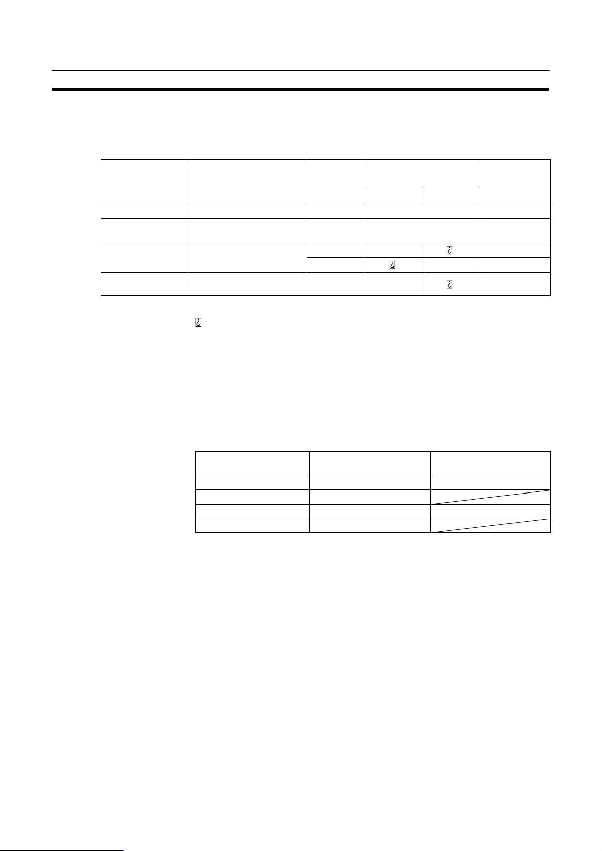
Possible Combinations
1-1 Possible Combinations
The table below shows the combinations that can be connected.
Chapter 1-1
PT Type Model Connector Connection to Mitsubishi
A (Computer Link)
RS-232C RS-422A
NT20S NT20S-ST121-EV3 RS-232C f f
NT600S
NT30/NT30C NT30-ST131-E
NT30/NT30C
(*1)
NT620S/NT620C
(*1)
NT600S-ST121-EV3
NT600S-ST211-EV3
NT30-ST131-E
NT30C-ST141-E
NT620S-ST211-E
NT620C-ST141-E
RS-232C f
RS-232C f f
RS-422A f
RS-232C f
Connection to
Mitsubishi FX
(Programming
console)
f: Direct connection
Via RS-232C/RS-422A convertor unit
: Connection not possible
(*1) In order to use NT30/NT30C, NT620S/NT620C in multi-vendor systems, a
dedicated system program must be installed in the PT using the “NT series
system installer”.
The relationship between the PCs that can be connected and the direct connection
version is shown in the table below.
Connection to Mitsubishi A
(Computer Link)
NT20S V4, V5 V4, V5
NT600S V4, V5
NT30/NT30C V4 V4
NT620S/NT620C V1 to V4
Connection to Mitsubishi
FX (Programming console)
1-2
Page 11

Installing the System Program
1-2 Installing the System Program
In order to use an NT30/NT30C or NT620S/NT620C in a multi-vendor system, a
dedicated system program must be installed in the PT using the “NT series system
installer” shown in the table below.
Model Applicable PC
NT30-ZS3AT-EMV1 Mitsubishi A series
NT620-ZS3AT-EMV1 Mitsubishi A series
For details on how to operate the system installer, refer to its instruction manual, or
the PT Operation manual.
Reference: Since NT20S and NT600S already have a dedicated system program written into
them, this installation is not required for them. However, some PT models cannot
be used in multi-vendor systems: check the situation for the model used by referring to “1-1 Possible Combinations” (page 1-2).
Chapter 1-2
Mitsubishi FX series
1-3
Page 12

Usable Support Tools
1-3 Usable Support Tools
When using the PT in a multi-vendor system, one of the following support tools
must be used.
NT-ZA3AT-EV2 (Ver.2.3j)
The programmable controllers (PC) that can be connected to the PT are determined by the “Direct Macn Type” data set in the screen data memory board. Accordingly, screen data complying with the programmable controller to be connected must be transferred to the PT in advance.
The “Direct Macn T ype” is set with the support tool. The applicable programmable
controllers (PCs) depending on the “Direct Macn Type” setting are as follows.
Direct Macn Type Applicable Programmable Controller (PLC)
NONE For connections without direct connection (e.g. RS-232C)
OMRON For connection to an OMRON C series or CVM1/CV se-
MEL-A For connection to a Mitsubishi Electric MELSEC A series
MEL-FX For connection to a Mitsubishi Electric FX series PC
Chapter 1-3
ries PC, or for a memory link connection.
PC
1-4
Page 13

CHAPTER 2
Use with Mitsubishi A Series Computer Link Systems
This chapter describes how to make the connections and settings when a PT is connected to a Mitsubishi A series programmable controller in a computer link system.
2-1
Page 14
Usable PTs and PCs
2-1 Usable PTs and PCs
The PT, PC, and computer link module models that can be used in a computer link
system that uses Mitsubishi A series PCs are indicated here.
Usable PT Models
The PT models that can be used with a computer link system that uses Mitsubishi
A series PCs are tabled below.
When using NT30/NT30C, NT620S/NT620C, install the system program for Mitsubishi A computer links in advance with the “NT series system installer”.
PT Type Model
NT20S NT20S-ST121j-EV3
NT600S NT600S-ST121j-EV3
NT30 NT30-ST131j-E
NT30C NT30C-ST141j-E
NT620S NT620S-ST211j-E
NT620C NT620C-ST141j-E
Chapter 2-1
NT600S-ST211j-EV3
Reference: For the versions of the direct connection function that can be used, refer to “1-1
Possible Combinations” (page 1-2). For details on the direct connection function,
refer to the Operation manual for the PT model used.
2-2
Page 15

Usable PTs and PCs
Modules Mounted at the Connected PC
Connections to a Mitsubishi A series PC are made at a computer link module. The
table below lists the computer link modules to which the connection can be made
with each type of connector.
Chapter 2-1
Series CPU Module
A series A0J2CPU
A0J2HCPU
A1SCPU
A1SJCPU
A2SCPU
A2USCPU
A2USCPU-S1
A1NCPU
A2NCPU
A2NCPU-S1
A3NCPU
A3HCPU
A3MCPU
A2ACPU
A2ACPU-S1
A3ACPU
A2UCPU
A2UCPU-S1
A3UCPU
A1SJ71C24-R2
A1SJ71UC24-R2
Computer Link Module Used
RS-232C RS-422
A0J2-C214S1
A1SJ71C24-R4
A1SJ71UC24-R4
AJ71C24-S8
AJ71UC24
When the computer link module used is an AJ71C24-S8, A1SJ71C24-R2, or
A1SJ71C24-R4, the device range is restricted to that usable with AnA models
even if an AnU is used as the CPU module.
To use an extended device range with AnU, an A1SJ71UC24-R2,
A1SJ71UC24-R4, or AJ71UC24 must be used.
2-3
Page 16
Connection
(M3.5)
2-2 Connection
The NT20S, NT600S and NT620S/NT620C have an RS-232C connector, while
the NT30/NT30C have an RS-232C connector and an RS-422A terminal block;
some computer link modules have an RS-232C connector and some have an
RS-422A terminal block. This section describes the methods for connection with
these connectors and terminal block.
Make cables that are suitable for the conditions of use, following the wiring details
given in this section.
Parts Required for Connection
The connectors, connector covers, crimp terminals, and recommended cables for
use with OMRON products are described here.
For details on the connectors, connector covers, and crimp terminals used at the
computer link module side, refer to the manual for the computer link module.
F Parts for RS-232C (Common to PT and NT-AL001)
Part Model Remarks
Connector XM2A-0901 9-pin type, made by OMRON
Connector cover XM2S-0911 9-pin type, made by OMRON
Cable AWG285P
Chapter 2-2
DE-9P 9-pin type, made by JAE
DE-CI-J6 9-pin type, made by JAE
Multi-core shielded cable, made
IFVV-SB
CO-MA-VV-SB
5P28AWG
by Fujikura, Ltd
Multi-core shielded cable, made
by Hitachi Cable, Ltd
2-4
F Recommended Parts for RS-422A Terminal Block (for NT30/NT30C)
<Appropriate crimp terminals>
Fork type Round type
6.2 mm or less 6.2 mm or less
Part Model Remarks
Crimp terminal
(M3.5)
Cable H-9293A
2-YS3A Fork type, made by Japan Sold-
erless Terminal MFG
2-YAS3.5 Fork type, made by Fuji Terminal
2Y-3.5 Fork type, made by Nichifu Ter-
minal
2-3.5 Round type, made by Japan
Solderless Terminal MFG
V2-S3.5 Round type, made by Fuji Termi-
nal
2-3.5 Round type, made by Nichifu
Terminal
Made by Hirakawa Hewtech
(CO-HC-ESV-3P7/0.2)
corp.
Page 17

Connection
F Recommended Parts for RS-422A Terminal Blocks (For NT-
AL001)
<Appropriate crimp terminals>
Fork type Round type
6.2 mm or less 6.2 mm or less
Part Model Remarks
Crimp terminal Y1.25-3.5L Fork type, made by molex
(M3)
(*1)
1.25-N3A Fork type, made by Japan Sold-
erless Terminal MFG
Chapter 2-2
(*1) Appropriate wire size: 0.3 to 0.75 mm
2
Connection Between RS-232C (PT) and RS-232C (Computer Link)
Computer link module
PT
Mitsubishi A series PC
9-pin
connector
Caution: After connecting a communication cable, always secure it with the screws.
Host interface connector
(RS-232C, 9-pin type)
Cable with RS-232C connector
(maximum length: 15 m)
25-pin connector/
9-pin connector
Otherwise the cable may disconnect, causing operation to fail.
F Wiring When Computer Link Module has a 25-pin Connector
There is a shielding wire at the computer link module side only: connect it to the
connector cover and to the No.1 pin (FG).
Mitsubishi computer link module
Pin No. Abbrev.
1
2
3
4
5
6
7
8
9
FG
SD
RD
RS
CS
DR
SG
CD
ER
RS-232C
interface
(25-pin)(9-pin)
RS-232C
interface
PT
FG
SD
RD
RS
CS
+5V
SG
Pin No.Abbrev.
1
2
3
4
5
6
7
8
9
Shielding wire
2-5
Page 18

Connection
Chapter 2-2
F Wiring When Computer Link Module has a 9-pin Connector
Mitsubishi computer link module
Pin No. Abbrev.
1
2
3
4
5
6
7
8
CD
RD
SD
ER
SG
DR
RS
CS
RS-232C
interface
9
(9-pin)(9-pin)
RS-232C
interface
PT
FG
SD
RD
RS
CS
+5V
SG
Pin No.Abbrev.
1
2
3
4
5
6
7
8
9
Shielding wire
Connection Between RS-232C (PT) and RS-422A (Computer Link Module)
Computer link module
PT
Mitsubishi A series PC
9-pin
connector
Host interface connector
(RS-232C, 9-pin type)
Cable with RS-232C connector
(maximum length: 15 m)
Caution: After connecting a communication cable, always secure it with the screws.
Otherwise the cable may disconnect, causing operation to fail.
Note: When connecting to a terminal block, always use crimp terminals.
F Wiring Between PT and NT-AL001
RS-232C
interface
RS-232C/RS-422A
convertor
unit (NT-AL001)
9-pin connector
PT
FG
SD
RD
RS
CS
+5V
SG
(9-pin)
RS-422A terminal block
RS-422A cable
(maximum length: 500 m)
NT-AL001 RS-232C connector
Pin No.Abbrev.
1
Shielding wire
2
3
4
5
6
7
8
9
Pin No. Abbrev.
Connector cover
2
3
4
5
6
7
8
9
SD
RD
RS
CS
+5V
DR
ER
SG
RS-232C
interface
(9-pin)
2-6
Page 19

Connection
Chapter 2-2
F Wiring Between NT-AL001 and Computer Link Module
Make the connections between SDB and SDA, and RDB and RDA, with twisted
pair wires
NT-AL001 RS-422A terminal block
Pin No.Abbrev.
8
7
6
5
4
3
2
1
RS-422A
interface
CSA ( –)
CSB (+)
RDA (–)
RDB (+)
SDA ( –)
SDB (+)
SG
GND
Shielding wire
Computer link module
Abbrev.
SDA (+)
SDB (–)
RDA (+)
RDB (–)
SG
FG
RS-422A
interface
Connection Between RS-422A (PT) and RS-422A (Computer Link Module)
Computer link module
PT
Mitsubishi A series PC
RS-422A terminal block
RS-422A cable (maximum length: 500 m)
RS-422A terminal
block
Note: When connecting to a terminal block, always use crimp terminals.
F Wiring
Make the connections between SDB and SDA, and RDB and RDA, with twisted
pair wires.
PT RS-422A terminal block
Abbrev.
RS-422A
interface
SDA ( –)
SDB (+)
RDA (–)
RDB (+)
Shielding wire
Computer link module
Abbrev.
SDA (+)
SDB (–)
RDA (+)
RDB (–)
SG
FG
RS-422A
interface
2-7
Page 20

Connection
Connection Between RS-422A (PT) and RS-232C (Computer Link)
Computer link module
PT
Mitsubishi A series PC
RS-232C/RS-422A
RS-422A
terminal
block
convertor unit
(NT-AL001)
25-pin connector/
9-pin connector
Chapter 2-2
RS-422A cable
(maximum length: 500 m)
9-pin cable
Cable with RS-232C connector
(maximum length: 15 m)
Caution: After connecting a communication cable, always secure it with the screws.
Otherwise the cable may disconnect, causing operation to fail.
Note: When connecting to a terminal block, always use crimp terminals.
F Wiring Between PT and NT-AL001
Make the connections between SDB and SDA, and RDB and RDA, with twisted
pair wires.
PT RS-422A terminal block
Abbrev.
RS-422A
interface
SDA ( –)
SDB (+)
RDA (–)
RDB (+)
Shielding wire
NT-AL001 RS-422A terminal block
Pin No. Abbrev.
8
CSA ( –)
7
CSB (+)
6
RDA (–)
5
RDB (+)
4
SDA ( –)
3
SDB (+)
2
1
SG
GND
RS-422A
interface
2-8
Page 21

Connection
Chapter 2-2
F Wiring to NT-AL001 when Computer Link Module has 25-pin Connector
Connect the power supply to the NT -AL001 (5 VDC) at pin No.6 (+5V) and pin No.9
(SG) of the RS-232C connector.
NT-AL001 RS-232C connector
Pin No.Abbrev.
Connector cover
2
3
4
5
6
7
8
9
Shielding wire
RS-232C
interface
SD
RD
RS
CS
+5V
DR
ER
SG
0V+5V
F Wiring to NT-AL001 when Computer Link Module has 9-pin Connector
Connect the power supply to the NT -AL001 (5 VDC) at pin No.6 (+5V) and pin No.9
(SG) of the RS-232C connector.
NT-AL001 RS-232C connector
Pin No.Abbrev.
Connector cover
2
3
4
5
6
7
8
9
Shielding wire
0V+5V
RS-232C
interface
SD
RD
RS
CS
+5V
DR
ER
SG
Mitsubishi computer link module
Pin No. Abbrev.
1
2
3
4
5
6
7
8
9
FG
SD
RD
RS
CS
DR
SG
CD
ER
RS-232C
interface
(25-pin)(9-pin)
Mitsubishi computer link module
Pin No. Abbrev.
1
2
3
4
5
6
7
8
CD
RD
SD
ER
SG
DR
RS
CS
9
(9-pin)(9-pin)
RS-232C
interface
2-9
Page 22

Setting
2-3 Setting
Settings at the PT
Reference: Set the other memory switches in accordance with the conditions of use.
Chapter 2-3
This chapter describes the settings required at each device in order to use a computer link system that uses Mitsubishi A series PCs.
Make the following settings in the PT’s maintenance mode by using the memory
switches. When using NT30/NT30C or NT620S/NT620C, install the system program for Mitsubishi A computer links in advance using the “NT series system installer”.
Item Setting
Port select (NT30/NT30C only) RS-232C or RS-422
Comm. Type (*) Computer link
Baud Rate 9600 bps or 19200 bps
PC type AnN, AnA, or AnU
*:The screen representation of the items to be set differs a little according to the
PT model.
For the “PC type” item, set the type of CPU module as follows.
Setting CPU Module
AnN A0J2CPU A0J2HCPU
A1SCPU A1SJCPU
A2SCPU A2NCPU A2NCPU-S1
A3NCPU A3HCPU A3MCPU
AnA A2ACPU A2ACPU-S1
A3ACPU
AnU A2UCPU A2UCPU-S1
A2USCPU A2USCPU-S1
A3UCPU
2-10
Page 23

Setting
Reference: Set the other DIP switches in accordance with the conditions of use.
Settings for NT-AL001
Chapter 2-3
NT30/NT30C DIP switch settings
When using RS-422A with NT30/NT30C, set DIP switches 2 to 8 to “ON” (terminal
resistor used).
When using the RS-232C/RS-422 convertor unit (NT-AL001), set the RS-422A
communication conditions with the DIP switches as shown in the figure below.
(Factory setting)
[SW1-1] Not used (always ON)
[SW1-2] Setting for built-in terminal resistor
ON Terminal resistor used
[SW1-3, 4] Selection of 2-wire type/4-wire type
SW1-3 SW1-4
OFF
ON
[SW1-5, 6] Selection of RS-422A transmission mode
SW1-5 SW1-6
OFF
ON
4-wire type
Transmission at any time
2-11
Page 24

Setting
Computer Link Module Settings
After connecting the PT and PC, set the conditions in the table below at the computer link module at the PC side.
Set these conditions using the switches provided on each type of module by following the instructions given below.
For a detailed explanation of the setting method, refer to the Operation Manual for
each module.
Item Setting
I/O port
Baud rate
Transmission
format
Parity
Control protocol
Unit No.
(Station number)
<A0J2-C214S1>
Chapter 2-3
When using an RS-232C connector When using an RS-422A terminal block
RS-232C RS-422A
Set the same baud rate as set at the PT.
ASCII 7 bits, 2 stop bits
Even
Type 1 Type 5
00
Unit No. (Station number) setting (SW3/SW4)
Set both SW3 and SW4 to “0”.
Transmission control protocol setting (SW5)
When using an RS-232C connector, set to “1”.
When using an RS-422A terminal block, set to “5”.
Computer link/multidrop link selection (SW10)
Set to “ON” (computer link).
Main channel setting (SW11)
When using an RS-232C connector, set to “OFF” (RS-232C).
When using an RS-422A terminal block, set to “ON” (RS-422A).
“Write during run” enable/disable setting (SW12)
Set to “ON” (enabled).
2-12
Transmission speed setting (SW13 to SW15)
SW13 SW14 SW15
ON
OFF
OFFONON
ON19,200bps
9,600bps
Data length setting (SW16)
Set to “OFF” (7 bits).
Parity check yes/no setting (SW17)
Set to “ON” (yes).
Parity (odd/even) setting (SW18)
Set to “ON” (even).
Stop bit setting (SW19)
Set to “ON” (2 bits).
Sum check yes/no setting (SW20)
Set to “ON” (yes).
Transmission side terminal resistor present/absent setting (SW22)
Set to “ON” (present) (setting invalid when RS-232C is used).
Receiving side terminal resistor present/absent setting (SW23)
Set to “ON” (present) (setting invalid when RS-232C is used).
Page 25

Setting
<AJ71C24-S8>
Unit No. (Station number) setting
Set both switches to “0”.
Transmission control protocol setting
When using an RS-232C connector, set to “1”.
When using an RS-422A terminal block, set to “5“.
Main channel setting (SW11)
When using an RS-232C connector, set to “OFF” (RS-232C).
When using an RS-422A terminal block, set to “ON” (RS-422A).
Data length setting (SW12)
Set to “OFF” (7 bits).
Transmission speed setting (SW13 to SW15)
SW13 SW14 SW15
ON
OFF
OFFONON
ON19,200bps
9,600bps
Parity check yes/no setting (SW16)
Set to “ON” (yes).
Chapter 2-3
Parity (odd/even) setting (SW17)
Set to “ON” (even).
Stop bit setting (SW18)
Set to “ON” (2 bits).
Sum check yes/no setting (SW21)
Set to “ON” (yes).
“Write during run” enable/disable setting (SW22)
Set to “ON” (enabled).
Transmission side terminal resistor present/absent setting (SW23)
Set to “ON” (present) (setting invalid when RS-232C is used).
Receiving side terminal resistor present/absent setting (SW24)
Set to “ON” (present) (setting invalid when RS-232C is used).
2-13
Page 26

Setting
<AJ71UC24>
Transmission control protocol setting
When using an RS-232C connector, set to “1”.
When using an RS-422A terminal block, set to “5”.
Unit No. (Station number) setting
Set both switches to “0”.
Main channel setting (SW11)
When using an RS-232C connector, set to “OFF” (RS-232C).
When using an RS-422A terminal block, set to “ON” (RS-422A).
Data length setting (SW12)
Set to “OFF” (7 bits).
Transmission speed setting (SW13 to SW15)
SW13 SW14 SW15
ON
OFF
OFFONON
ON19,200bps
9,600bps
Parity check yes/no setting (SW16)
Set to “ON” (yes).
Chapter 2-3
Parity (odd/even) setting (SW17)
Set to “ON” (even).
Stop bit setting (SW18)
Set to “ON” (2 bits).
Sum check yes/no setting (SW21)
Set to “ON” (yes).
“Write during run” enable/disable setting (SW22)
Set to “ON” (enabled).
Computer link/multidrop link selection (SW23)
Set to “ON” (computer link).
2-14
Page 27

Setting
<A1SJ71UC24-R2, A1SJ71C24-R2> (RS-232C dedicated)
Transmission control protocol setting
Set to “1”.
“Write during run” enable/disable setting (SW04)
Set to “ON” (enabled).
Transmission speed setting (SW05 to SW07)
SW05 SW06 SW07
ON
OFF
OFFONON
ON19,200bps
9,600bps
Data length setting (SW08)
Set to “OFF” (7 bits).
Parity check yes/no setting (SW09)
Set to “ON” (yes).
Parity (odd/even) setting (SW10)
Set to “ON” (even).
Chapter 2-3
Stop bit setting (SW11)
Set to “ON” (2 bits).
Sum check yes/no setting (SW12)
Set to “ON” (yes).
2-15
Page 28

Setting
<A1SJ71UC24-R4, A1SJ71C24-R4> (RS-422A dedicated)
Unit No. (Station number) setting
Set both switches to “0”.
Transmission control protocol setting
Set to “5”.
Computer link/multidrop link selection (SW02)
Set to “ON” (computer link).
“Write during run” enable/disable setting (SW04)
Set to “ON” (enabled).
Transmission speed setting (SW05 to SW07)
SW05 SW06 SW07
ON
OFF
OFFONON
ON19,200bps
9,600bps
Data length setting (SW08)
Set to “OFF” (7 bits).
Parity check yes/no setting (SW09)
Set to “ON” (yes).
Chapter 2-3
Parity (odd/even) setting (SW10)
Set to “ON” (even).
Stop bit setting (SW11)
Set to “ON” (2 bits).
Sum check yes/no setting (SW12)
Set to “ON” (yes).
2-16
Page 29

Allocation Areas
2-4 Allocation Areas
This chapter describes the types of area to which bits and words can be allocated,
and the ranges of these areas for each PC.
Bits and Words Allocated to the PC
Bits and words can be allocated to Mitsubishi A series PCs as follows.
Symbol Area Name Bit
D Data registers ✓ ✓ ✓
M Internal relays ✓ ✓ ✓
T Timers
C Counters
L Latching relays ✓ ✓ ✓
B
W
X
Y
R File registers ✓ ✓ ✓
Link relays
(hexadecimal input)
Link registers
(hexadecimal input)
Input relays
(hexadecimal input)
Output relays
(hexadecimal input)
Chapter 2-4
Word
Numeric
Value
✓ ✓ ✓
✓ ✓ ✓
✓ ✓ ✓
✓ ✓ ✓
Character
String(*)
(*) Includes the PT status control area and PT status notify area
✓: Possible Possible (1 word only) : Not possible
F Restrictions on Use
The restrictions and cautions that apply specifically when using a PT with a computer link system that uses Mitsubishi A series PCs are presented here. For details on other, general restrictions, refer to the Operation manual for the PT.
Screen switching
To switch screens by specifying a screen number in the “screen switch setting” of
the PT status control area, specify the screen number in BCD (binary coded decimal).
Specifying memory table numbers
When specifying memory table numbers in the PT status control area, and when
specifying memory table numbers by indirect specification, use BCD (binary
coded decimal).
2-17
Page 30

Allocation Areas
Chapter 2-4
Setting the PT Clock function
When setting the time with the PT’s internal clock function, specify the value in
BCD (binary coded decimal).
Bit notification
When elements for which statuses are notified by bits - such as touch switches,
extended I/O inputs, bit memory tables, etc. - are allocated to word devices (D, W ,
R), since the notification is in word units, all bits other than those used for the notification will be set to “0” (OFF).
2-18
Page 31

Allocation Areas
Mitsubishi A Series PC Allocation Areas
Chapter 2-4
Area
Area
PC
A0J2CPU 0000 to 01DF 0000 to 01DF
A0J2HCPU 0000 to 01DF 0000 to 01DF
A1SCPU 0000 to 00FF 0000 to 00FF
A1SJCPU 0000 to 00FF 0000 to 00FF
A2SCPU 0000 to 01FF 0000 to 01FF
A2NCPU 0000 to 01FF 0000 to 01FF
A2NCPU-S1 0000 to 03FF 0000 to 03FF
A3NCPU 0000 to 07FF 0000 to 07FF
A3HCPU 0000 to 07FF 0000 to 07FF
A3MCPU 0000 to 07FF 0000 to 07FF
A2ACPU 0000 to 01FF 0000 to 01FF
A2ACPU-S1 0000 to 03FF 0000 to 03FF B0000 to B0FFF
A3ACPU 0000 to 07FF 0000 to 07FF
A2UCPU 0000 to 01FF 0000 to 01FF
A2UCPU-S1 0000 to 03FF 0000 to 03FF
A2USCPU 0000 to 01FF 0000 to 01FF
A2USCPU-S1 0000 to 03FF 0000 to 03FF
A3UCPU 0000 to 07FF 0000 to 07FF
Input Relays
(X)
Output
Relays (Y)
Link Relays (B)
B0000 to B03FF M0000 to M2047 L0000 to L2047
B0000 to B1FFF
B0000 to B1FFF
Bit Devices (Bit Units)
Internal Relays
(M)
M0000 to M8191 L0000 to L8191
Latch Relays
(L)
Special Internal
Relays (M)
M9000 to M9255
Notes: S The values indicated in the table above are the ranges that can actually be set with the
support tool and used by the PT.
S The ranges actually usable differ according to the system configuration.
2-19
Page 32

Allocation Areas
Chapter 2-4
Area
Area
PC
A0J2CPU – D9000 to D9127
A0J2HCPU
A1SCPU
A1SJCPU
A2SCPU
A2NCPU
A2NCPU-S1
A3NCPU
A3HCPU
A3MCPU
A2ACPU
A2ACPU-S1
A3ACPU
A2UCPU
A2UCPU-S1
A2USCPU
A2USCPU-S1
A3UCPU
Data Registers (D) Timers (T) Counters (C) Link Registers (W) File Registers (R)
D0000 to D1023
D0000 to D6143
D0000 to D6143
D0000 to D8191
D0000 to D8191
T0000 to T0255 C0000 to C0255 W0000 to W03FF
T0000 to T2047 C0000 to C1023 W0000 to W0FFF
T0000 to T2047 C0000 to C1023 W0000 to W1FFF
T0000 to T2047 C0000 to C1023 W0000 to W1FFF
Word Devices
R0000 to R4095
R0000 to R8191
Special Data
Registers (D)
D9000 to D9255
D9000 to D9255
Notes: S The values indicated in the table above are the ranges that can actually be set with the
support tool and used by the PT.
S The ranges actually usable differ according to the system configuration.
S The values accessed with timers and counters are the timer and counter present values.
2-20
Page 33

Specific Error and Their Remedies
2-5 Specific Errors and Their Remedies
This chapter describes the specific errors that may occur when using the PT in a
computer link system that uses Mitsubishi A series PCs, and the remedies to
employ when they occur.
Setting Errors
If an area that does not exist in the PC is specified when creating a PT screen with
the support tool, the screen shown below is displayed during PT operation.
Confirm
Setting error
XXXXX
YYYYY
XXXXX: Device type
YYYYY: Device number
Chapter 2-5
Reception Errors
If this happens, first check that the area at the PC being used has been secured,
then set the correct device.
If a reception error occurs during PT operation, the screen shown below is displayed.
<Error details>
SCI. parity error
SCI. overrun error
Receive error
SCI. framing error
Buffer overflow
Time out
NAK reception error
PC No. error
Station No. error
Sum value error
2-21
Page 34

Specific Error and Their Remedies
The errors that occur specifically with computer link systems that use Mitsubishi A
series PCs are described below. For details on errors other than those indicated
below, refer to the Operation manual for the PT.
PC Number
error
Exchange No.
error
Sum check
error
Chapter 2-5
Message Cause Corrective Action
S Due to noise, the data has
been changed on the transmission line.
S The station No. at the PC side
has been changed.
S The PC has sent erroneous
data.
S Due to noise, the data has
been changed on the transmission route.
S The PC has sent erroneous
data.
S Due to noise, the data has
been changed on the transmission line.
S If the system is used at a site
subject to a lot of noise, use
cables with protection against
noise on the transmission
route.
S Set the station No. at the PC
side to “0”.
S Check the operation at the PC
side.
S If the system is used at a site
subject to a lot of noise, use
cables with protection against
noise on the transmission
route.
S Check the operation at the PC
side.
S If the system is used at a site
subject to a lot of noise, use
cables with protection against
noise on the transmission
route.
2-22
Page 35

CHAPTER 3
Use With Mitsubishi FX
This chapter describes how to make the connections and settings when a PT is connected to a Mitsubishi FX series programmable controller.
3-1
Page 36

Applicable PTs and PCs
3-1 Applicable PTs and PCs
The PT and PC models that can be used with Mitsubishi FX series PCs are indicated here.
Usable PT Models
The PT models that can be used with the Mitsubishi FX series are tabled below.
When using NT30/NT30C, install the system program for Mitsubishi FX in advance using the “NT series system installer”.
PT Type Model
NT20S NT20S-ST121j-EV3
NT30 (*) NT30-ST131j-E
NT30C (*) NT30C-ST141j-E
(*) Only an RS-232C connector can be used.
Reference: For the versions of the direct connection function that can be used, refer to “1-1
Possible Combinations” (page 1-2). For details on the direct connection function,
refer to the Operation manual for the PT model used.
Chapter 3-1
Modules mounted at the Connected PC
When the connection is to a Mitsubishi FX series PC, the programming console
connector of the main base unit is used. The table below lists main base units to
which connection is possible.
Type Mode
FX0 FX0-14MR FX0-20MR FX0-30MR FX0-14MT FX0-20MT FX0-30MT
FX
0-14MR-D FX0-20MR-D FX0-30MR-D FX0-14MT-D FX0-20MT-D FX0-30MT-D
FX0N FX0N-40MR FX0N-60MR FX0N-40MT FX0N-60MT
FX1 FX1-16MR FX1-24MR FX1-32MR FX1-48MR FX1-64MR FX1-80MR
FX
1-16MT FX1-24MT FX1-32MT FX1-48MT FX1-64MT FX1-80MT
FX2 FX2-16MR FX2-24MR FX2-32MR FX2-48MR FX2-64MR FX2-80MR
FX
2-128MR
FX
2-16MS FX2-24MS FX2-32MS FX2-48MS FX2-64MS FX2-80MS
FX
2-16MT FX2-24MT FX2-32MT FX2-48MT FX2-64MT FX2-80MT
FX
2-128MT
FX
2-24MR-A1 FX2-48MR-A1 FX2-64MR-A1
FX
2-24MR-D FX2-48MR-D FX2-64MR-D FX2-80MR-D
FX
2-48MT-D FX2-80MT-D
FX
2-32MT-C FX2-64MT-C
FX2C FX2C-64MT FX2C-96MT FX2C-128MT FX2C-160MT
3-2
Page 37

Connection
3-2 Connection
The connection is made between the RS-232C connector of the PT to the Mitsubishi FX series PC via an RS-232C/RS-422A convertor unit (type NT-AL001).
Make the cables in accordance with the wiring schemes shown in this section, and
in accordance with the conditions of use.
Parts Required for Connection
The connectors, connector covers, crimp terminals, and recommended cables for
use with OMRON products are described here.
For details on the connectors, connector covers, and crimp terminals used with
Mitsubishi products, refer to the manual for the Mitsubishi product.
F Parts for RS-232C connector (Common to PT and NT-AL001)
Part Model Remarks
Connector XM2A-0901 9-pin type, made by OMRON
Connector cover XM2S-0911 9-pin type, made by OMRON
Cable AWG28X5P
DE-9P 9-pin type, made by JAE
DE-CI-J6 9-pin type, made by JAE
Multi-core shielded cable, made by Fujiku-
IFVV-SB
CO-MA-VV-SB
5PX28AWG
ra, Ltd
Multi-core shielded cable, made by Hitachi
Cable, Ltd
Chapter 3-2
F Recommended Parts for RS-422A Terminal Blocks (For NT-AL001)
<Appropriate crimp terminals>
Fork type
6.2 mm or less
Part Model Remarks
Crimp terminal (M3) Y1.25-3.5L Fork type, made by Molex
(*1)
(*1) Appropriate wire size: 0.3 to 0.75 mm
Round type
6.2 mm or less
1.25-N3A Fork type, made by Japan Solderless Terminal MFG
2
3-3
Page 38

Connection
Connection Method
Chapter 3-2
9-pin connector
RS-232C cable
(maximum length: 15 m)
Caution: After connecting a communication cable, always secure it with the screws.
NT20S
RS-232C/RS-422A convertor unit
(NT-AL001)
RS-422A cable
(maximum length: 500 m)
9-pin connector
Main base unit
Mitsubishi FX series PC
25-pin connector
Otherwise the cable may disconnect, causing operation to fail.
Note: When connecting to a terminal block, always use crimp terminals.
F Wiring Between PT and NT-AL001
PT NT-AL001 RS-232C connector
RS-232C
interface
FD
SD
RD
RS
CS
+5V
SG
(9-pin)
Pin No.Abbrev.
1
2
3
4
5
6
7
8
9
Shielding
wire
Pin No. Abbrev.
Connector cover
2
3
4
5
6
7
8
9
SD
RD
RS
CS
+5V
DR
ER
SG
(9-pin)
RS-232C
interface
3-4
Page 39

Connection
Chapter 3-2
F Wiring Between NT-AL001 and PC
When using FX1, FX2, and FX2C, connect a cable with the wiring scheme shown
below directly to the programming console connector of the PC.
The programming console connectors of FX0 and FX0N have a different shape;
with these types connect a cable with the wiring scheme shown below to an
FX-20P-CADP cable made by Mitsubishi, then connect the FX-20P-CADP to the
programming console connector of the PC.
NT-AL001 RS-422A terminal block FX series PC
RS-422A
interface
FG
SG
SDB
SDA
RDB
RDA
RSB
RSA
Pin No.Abbrev.
1
2
3
4
5
6
7
8
Shielding
wire
Pin No.
1
2
3
4
15
16
17
25-pin8-pin terminal block
RS-422A
interface
Make the connections between SDB and SDA, RDB and RDA, and RSB and RSA,
with twisted pair wires.
3-5
Page 40

Setting
3-3 Setting
Settings at the PT
Reference: Set the other memory switches in accordance with the conditions of use.
Chapter 3-3
This chapter describes the settings required at each device in order to use the programming console connector of a Mitsubishi FX series PC.
Make the following settings in the PT’s maintenance mode by using the memory
switches. When using NT30/NT30C, install the system program for Mitsubishi FX
in advance using the “NT series system installer”.
F When using NT20S
Item Setting
Comm. Type With FX0 :MELSEC-FX0
With FX0N :MELSEC-FX0N
With FX
With FX2, FX2C :MELSEC-FX2
1 :MELSEC-FX1
F When using NT30/NT30C
Item Setting
Port select RS-232C
Comm. Type With FX0 :MELSEC-FX0
With FX0N :MELSEC-FX0N
With FX
With FX2, FX2C :MELSEC-FX2
1 :MELSEC-FX1
3-6
Page 41

Setting
Settings at the NT-AL001
When using the RS-232C/RS-422 convertor unit (NT-AL001), set the RS-422A
communication conditions with the DIP switches as shown in the figure below.
Chapter 3-3
(Factory setting)
PC Settings
[SW1-1] Not used (always ON)
[SW1-2] Setting for built-in terminal resistor
ON Terminal resistor used
[SW1-3, 4] Selection of 2-wire type/4-wire type
SW1-3 SW1-4
OFF
ON
[SW1-5, 6] Selection of RS-422A transmission mode
SW1-5 SW1-6
OFF
ON
4-wire type
Transmission at any time
No particular settings have to be made at the PC in order to use the PT with a programming console connector.
3-7
Page 42

Allocation Areas
3-4 Allocation Areas
This chapter describes the types of area to which bits and words can be allocated,
and the ranges of these areas for each PC.
Bits and Words Allocated to the PC
Bits and words can be allocated to Mitsubishi FX series PCs as follows.
Symbol Area Name Bit
D Data registers
M Internal relays
T Timers
C Counters
S State relays
X Input relays
Y Output relays
(*) Includes the PT status control area and PT status notify area
✓ : Possible
: Possible (1 word only)
: For C0 to C199, 1 word possible; for C200 and higher,
2 words possible
: Not possible
Chapter 3-4
Word
Numeric
Value
✓ ✓
✓ ✓ ✓
✓ ✓ ✓
✓ ✓ ✓
✓ ✓ ✓
Character
String
(*)
Reference: Allocations cannot be made to the special use areas for data registers (D) and aux-
iliary registers (M).
F Restrictions on Use
The restrictions and cautions that apply specifically when using a PT with the programming console connector of a Mitsubishi FX series PC are presented here.
For details on other, general restrictions, refer to the Operation manual for the PT.
Screen switching
To switch screens by specifying a screen number in the “screen switch setting” of
the PT status control area, specify the screen number in BCD (binary coded decimal).
Specifying memory table numbers
When specifying memory table numbers in the PT status control area, and when
specifying memory table numbers by indirect specification, use BCD (binary
coded decimal).
Setting the PT Clock function
When setting the time with the PT’s internal clock function, specify the value in
BCD (binary coded decimal).
3-8
Page 43

Allocation Areas
Bit notification
When elements for which statuses are notified by bits - such as touch switches,
extended I/O inputs, bit memory tables, etc. since the notification is in word units,
all bits other than those used for the notification will be set to “0” (OFF).
Bit and Word Allocations to Bit Devices (M, S, X, Y)
The allocation of bits and words to bit devices (M, S, X, Y) is described here.
For details on the ranges of the areas within which specification is possible, refer t o
“Mitsubishi FX Series PC Allocation Areas” (page 3-11).
F Bit Allocations
When allocating bits to bit devices, any number not outside the range for the area
can be specified. However, since host link access is in word (16 bit) units, the following points must be observed when allocating bits.
S Points to note when allocating to M (special relays) and S (state relays)
M and S devices are bit devices expressed in decimal in the case of Mitsubishi
FX series PCs. However, in the host link, data is written in word (16-bit) units.
Therefore, when data is written, all other bits in the same word are cleared to “0”
(“other bits in the same word” here means bits which have the same quotient
when divided by 16).
Chapter 3-4
S Points to note when allocating to X (input relays) and Y (output relays)
X and Y devices are bit devices expressed in octal in the case of Mitsubishi FX
series PCs. However , host link writing is in word (16-bit) units. Therefore, when
data is written, all other bits in the same word are cleared to “0” (since one word i s
16 bits, each of the following sequences of bits (least significant two digits) is
contained within one word: 00 to 17, 20 to 37, 40 to 57, and 60 to 77).
3-9
Page 44

Allocation Areas
Chapter 3-4
F Word Allocations
When allocating bits to bit devices, the following points relating to the method of
specification must be observed.
S Points to note when allocating to M (special relays) and S (state relays)
M and S devices are bit devices expressed in decimal in the case of Mitsubishi
FX series PCs. However, inside the PC, the bits are actually managed in units of
16. Therefore, when accessing words using word allocation, make the specification so that the first bit number is a multiple of 16.
S Points to note when allocating to X (input relays) and Y (output relays)
X and Y devices are bit devices expressed in octal in the case of Mitsubishi FX
series PCs. Therefore, when accessing words using word allocation, ensure
that the least significant two digits of the first bit number are “00”, “20”, “40”, or
“60”.
The area used for word allocation is as follows.
Number o f
allocated words
1 word
First word
First + 1 word
First + 14 bits
Word Allocations to Word Devices (D, T, C)
Word allocations to word devices (D, T, C) are described here.
It is impossible to make bit allocations to word devices.
Normally one word device occupies one word (16 bits). Therefore, when allocating a word to a word device, any number not outside the range for the area can be
specified. However, in the case of counters C200 and higher, one word device is
32 bits, i.e., it occupies 2 words. For details on the ranges of the areas within which
specification is possible, refer to “Mitsubishi FX Series PC Allocation Areas” (page
3-11).
The area used for word specification is as follows.
S Normal device
215 14 1 0
First + 2 bitsFirst + 15 bits
First + 1 bit
First + 17 bitsFirst + 30 bits
Bit
First + 0 bits
First + 16 bitsFirst + 18 bitsFirst + 31 bits
Number o f
allocated words
3-10
First word
First + 1 word
15 14 13 12 11 10 9 8 23456710
First word device (lower 16 bits)
First word device (upper 16 bits)
Bit
Page 45

Allocation Areas
S 32-bit devices from C200 onward
Number o f
allocated words
First word
First + 1 word
First word device
First + 1 word device
Mitsubishi FX Series PC Allocation Areas
Chapter 3-4
Bit15 14 13 12 11 10 9 8 23456710
Data
Type Unit
FX0 Bit ––– M0 to M511 ––– ––– S0 to S63 X0 to X177 X0 to X177
FX0N Word D0 to D31 M0 to M496 T0 to T55 C0 to C254 S0 to S48 X0 to X17 Y0 to Y17
FX1 Bit ––– M0 to M1023 ––– ––– S0 to S999 X0 to X177 X0 to X177
Word D0 to D127 M0 to M1008 T0 to T245 C0 to C254 S0 to S984 X0 to X17 Y0 to Y17
FX2
FX2
FX2C
Bit ––– M0 to M1023 ––– ––– S0 to S999 X0 to X177 X0 to X177
Word D0 to D511 M0 to M1008 T0 to T255 C0 to C255 S0 to S984 X0 to X17 Y0 to Y17
Registers
(D)
Auxiliary
Relays
(M)
Timers
(T)
Counters
(C)
State Relays
(S)
Input Relays
(X)
Output
Relays
(Y)
Notes: S The values indicated in the table above are the ranges that can actually be set
with the support tool and used by the PT.
S The ranges actually usable differ according to the system configuration.
3-11
Page 46

+
APPENDIX
This chapter describes the specifications of the connectors of OMRON products used for communications.
APP-1
Page 47

OMRON Product Connector Specifications
OMRON Product Connector Specifications
PT Connectors
F RS-232C connector specifications
S Connector type : RS-232C connector (9-pin)
S Electrical characteristics : Conform to EIA RS-232C
S Connection signals
Appendix A
APPENDIX A
Connector
Pin No.
1 Not used – –
2 Send data SD (TXD)
3 Receive data RD (RXD)
4 Request to send RS (RTS)
5 Clear to send CS (CTS)
6 +5V for convertor (max. 150 mA) +5V
9 Signal ground SG –
F RS-422A terminal block specifications (NT30/NT30C only)
S Connected terminal block : RS-422A terminal block (M3.5 screw)
S Electrical characteristics : Conform to EIA RS-422A
S Connection signals
Send data (–) SDA
Send data (+) SDB
Receive data (–) RDA
Receive data (+) RDB
Signal Name Abbreviation
Signal Name Abbreviation
Signal Direction
PT ↔ External Device
Signal Direction
PT ↔ External Device
APP-2
Page 48

OMRON Product Connector Specifications
RS-232C/RS-422 Convertor Unit (NT-AL001)
F RS-232C connector specifications
S Connector type : RS-232C connector (9-pin)
S Electrical characteristics : Conform to EIA RS-232C
S Connection signals
Appendix A
Connector
Pin No.
Connector
cover
1 Not used – –
2 Send data SD (TXD)
3 Receive data RD (RXD)
4
5
6 +5V for convertor (150 mA) +5V
7
8
9 Signal ground SG (GND) –
Grounding or earth for safety
purposes
Receive dataRequest to send
(shorted to CS internally)
Clear to send (shorted to RS internally)
Data set ready (shorted to ER
internally) *
Data terminal ready (shorted to
DR internally) *
Signal Name Abbreviation
FG –
RS (RTS)
CS (CTS)
DR (DSR) – *
ER (DTR) – *
Signal Direction
PT ↔ External Device
- The connector cover is connected to the functional ground terminal (pin No.1) of
the RS-422A terminal block.
* Pins No.7 and No.8 are connected internally to each other and do not have the
function as the control lines.
F RS-422A terminal block specifications
S Connected terminal block : RS-422A terminal block (M3 screw)
S Electrical characteristics : Conform to EIA RS-422A
S Connection signals
Connector
Pin No.
1 Functional ground FG –
2
3 Send data (+) SDB
4 Send data (–) SDA
5 Receive data (+) RDB
6 Receive data (–) RDA
7 Request to send (+) CSB
8 Request to send (–) CSA
Signal ground
Signal Name Abbreviation
SG (GND) –
Signal Direction
PT ↔ External Device
Note: The CSB and CSA signals are for special applications.
APP-3
Page 49

INDEX
B
Bit Allocations 3-9. . . . . . . . . . . . . . . . . . . . . . . . . . . . .
Bit and Word Allocations to Bit Devices (M, S, X, Y)
(for Mitsubishi FX) 3-9. . . . . . . . . . . . . . . . . . . . . . . . .
Bit notification
for Mitsubishi A computer links 2-18. . . . . .
for Mitsubishi FX 3-9. . . . . . . . . . . . . . . . . . .
Bits 2-17. . . . . . . . . . . . . . . . . . . . . . . . . . . . . . . . . . . . .
Bits and Words Allocated to the PC
for Mitsubishi A computer links 2-17. . . . . .
for Mitsubishi FX 3-8. . . . . . . . . . . . . . . . . . .
C
Clock function
for Mitsubishi A computer links 2-18. . . . . .
for Mitsubishi FX 3-8. . . . . . . . . . . . . . . . . . .
Computer link 2-2. . . . . . . . . . . . . . . . . . . . . . . . . . . . .
Mitsubishi A Series PC Allocation Areas 2-19. . . . .
Mitsubishi FX Series PC Allocation Areas 3-11. . . .
Modules Mounted at the Connected PC
for Mitsubishi A computer links 2-3. . . . . . .
for Mitsubishi FX 3-2. . . . . . . . . . . . . . . . . . .
P
Parts for RS-232C (Common to PT and NT-AL001)
for Mitsubishi A Computer links 2-4. . . . . . .
for Mitsubishi FX 3-3. . . . . . . . . . . . . . . . . . .
Parts Required for Connection
for Mitsubishi A computer links 2-4. . . . . . .
for Mitsubishi FX 3-3. . . . . . . . . . . . . . . . . . .
PC Settings
for Mitsubishi FX 3-7. . . . . . . . . . . . . . . . . . .
PC that can be connected 1-2. . . . . . . . . . . . . . . . . .
Possible Combinations 1-2. . . . . . . . . . . . . . . . . . . . .
Computer Link Module Settings
<A0J2-C214S1> 2-12. . . . . . . . . . . . . . . . . . .
<A1SJ71UC24-R2, A1SJ71C24-R2>
(RS-232C dedicated) 2-15. . . . . . . . . . . . . . .
<A1SJ71UC24-R4, A1SJ71C24-R4>
(RS-422 dedicated) 2-16. . . . . . . . . . . . . . . .
<AJ71C24-S8> 2-13. . . . . . . . . . . . . . . . . . . .
<AJ71UC24> 2-14. . . . . . . . . . . . . . . . . . . . .
Connection Method (for Mitsubishi FX) 3-4. . . . . . .
D
Direct connection version 1-2. . . . . . . . . . . . . . . . . . .
M
Methods for connection
(for Mitsubishi A computer links)
RS-232C (PT)-RS-232C
(Computer Link) 2-5. . . . . . . . . . . . . . . . . . . .
RS-232C (PT)-RS-422A
(Computer Link) 2-6. . . . . . . . . . . . . . . . . . . .
RS-422A (PT)-RS-232C
(Computer Link) 2-8. . . . . . . . . . . . . . . . . . . .
RS-422A (PT)-RS-422A
(Computer Link) 2-7. . . . . . . . . . . . . . . . . . . .
R
Recommended Parts for RS-422A Terminal Block
(for NT30/NT30C)
for Mitsubishi A Computer links 2-4. . . . . . .
Recommended Parts for RS-422A Terminal Blocks
(for NT-AL001)
for Mitsubishi A computer links 2-5. . . . . . .
for Mitsubishi FX 3-3. . . . . . . . . . . . . . . . . . .
RS-232C connector specifications
OMRON PT APP-2. . . . . . . . . . . . . . . . . . . .
NT-AL001 APP-3. . . . . . . . . . . . . . . . . . . . . .
RS-232C/RS-422 Convertor Unit
(NT-AL001) APP-3. . . . . . . . . . . . . . . . . . . . . . . . . . . .
RS-422A terminal block specifications
NT30/NT30C only APP-2. . . . . . . . . . . . . . .
NT-AL001 APP-3. . . . . . . . . . . . . . . . . . . . . .
S
Screen switching
for Mitsubishi A computer links 2-17. . . . . .
for Mitsubishi FX 3-8. . . . . . . . . . . . . . . . . . .
Page 50

Setting
for Mitsubishi A computer links 2-10. . . . . .
for Mitsubishi FX 3-6. . . . . . . . . . . . . . . . . . .
Setting for NT-AL001
for Mitsubishi A computer links 2-11. . . . . .
for Mitsubishi FX 3-7. . . . . . . . . . . . . . . . . . .
Specifying memory table numbers
for Mitsubishi A computer links 2-17. . . . . .
for Mitsubishi FX 3-8. . . . . . . . . . . . . . . . . . .
System installer 1-3. . . . . . . . . . . . . . . . . . . . . . . . . . .
U
Usable PT Models
for Mitsubishi A computer links 2-2. . . . . . .
for Mitsubishi FX 3-2. . . . . . . . . . . . . . . . . . .
W
Word Allocations 3-10. . . . . . . . . . . . . . . . . . . . . . . . .
Word Allocations to Word Devices (D, T, C)
(for Mitsubishi FX) 3-10. . . . . . . . . . . . . . . . . . . . . . . .
Words 2-17. . . . . . . . . . . . . . . . . . . . . . . . . . . . . . . . . .
Page 51

Revision History
A manual revision code appears as a suffix to the catalog number on the front cover of the manual.
Cat. No. V042-E1-1
Revision code
The following table outlines the changes made to the manual during each revision. Page numbers refer to the
previous version.
Revision code Date Revised content
1 April 1997 Original production
 Loading...