

Page 1
OS32C-DM Safety Laser Scanner with EtherNet/IP
This addendum is to be used in conjunction with the
OS32C User’s Manual (P/N 99863-0010 or Manual No. Z296-E1)
P/N 99863-0060 Rev.G
Cat. No. Z336-E1-07
Page 2

Original Detailed Instructions
Introduction
Thank you for purchasing the OS32C Safety Laser Scanner (herein after referred to as the "OS32C" ).
This is the instruction Manual describing how to connect the OS32C-xxx-DM to devices in EtherNet/IP systems and confirm the
connection.
This addendum is to be used in conjunction with the Safety Laser Scanner OS32C Series User’s Manual (Z296-E1) (herein after
referred to as the "OS32C User’s Manual".)
Always take into account the following points when using the OS32C:
Make sure OS32C is handled by a "Responsible Person" who is well aware of and familiar with the machine to be installed.
The term "Responsible Person" used in this Instruction Manual means the person qualified, authorized and responsible to secure
"safety" in each process of the design, installation, operation, maintenance services and disposition of the machine.
It is assumed that the OS32C will be used properly according to the installation environment, performance and function of the machine.
A responsible Person should conduct a risk assessment of the machine and determine the suitability of this product before installation.
Read this Manual thoroughly and understand its contents.
Trademarks
• Windows, Windows XP, Windows 7, Windows 8.1 and Windows 10 are either registered trademarks or trademarks of Microsoft
Corporation in the USA and other countries.
• ODVA, EtherNet/IP
•
Other company names and product names in this document are the trademarks or registered trademarks of their respective companies.
• Microsoft product screen shot(s) reprinted with permission from Microsoft Corporation.
TM
, DeviceNetTM, ControlNetTM, CIPTM and CIP SafetyTM are trademarks of ODVA, Inc.
Page 3

Introduction
Terms and Conditions Agreement
Warranties.
(a) Exclusive Warranty. Omron's exclusive warranty is that the Products will be free from defects in materials and
workmanship for a period of twelve months from the date of sale by Omron (or such other period expressed in writing
by Omron). Omron disclaims all other warranties, express or implied.
(b) Limitations. OMRON MAKES NO WARRANTY OR REPRESENTATION, EXPRESS OR IMPLIED, ABOUT NON-
INFRINGEMENT, MERCHANTABILITY OR FITNESS FOR A PARTICULAR PURPOSE OF THE PRODUCTS.
BUYER ACKNOWLEDGES THAT IT ALONE HAS DETERMINED THAT THE PRODUCTS WILL SUITABLY MEET
THE REQUIREMENTS OF THEIR INTENDED USE.
Omron further disclaims all warranties and responsibility of any type for claims or expenses based on infringement by the
Products or otherwise of any intellectual property right. (c) Buyer Remedy. Omron's sole obligation hereunder shall be, at
Omron's election, to (i) replace (in the form originally shipped with Buyer responsible for labor charges for removal or
replacement thereof) the non-complying Product, (ii) repair the non-complying Product, or (iii) repay or credit Buyer an
amount equal to the purchase price of the non-complying Product; provided that in no event shall Omron be responsible
for warranty, repair, indemnity or any other claims or expenses regarding the Products unless Omron's analysis confirms
that the Products were properly handled, stored, installed and maintained and not subject to contamination, abuse, misuse
or inappropriate modification. Return of any Products by Buyer must be approved in writing by Omron before shipment.
Omron Companies shall not be liable for the suitability or unsuitability or the results from the use of Products in
combination with any electrical or electronic components, circuits, system assemblies or any other materials or
substances or environments. Any advice, recommendations or information given orally or in writing, are not to be
construed as an amendment or addition to the above warranty.
See http://www.omron.com/global/
or contact your Omron representative for published information.
Limitation on Liability; Etc.
OMRON COMPANIES SHALL NOT BE LIABLE FOR SPECIAL, INDIRECT, INCIDENTAL, OR CONSEQUENTIAL
DAMAGES, LOSS OF PROFITS OR PRODUCTION OR COMMERCIAL LOSS IN ANY WAY CONNECTED WITH THE
PRODUCTS, WHETHER SUCH CLAIM IS BASED IN CONTRACT, WARRANTY, NEGLIGENCE OR STRICT LIABILITY.
Further, in no event shall liability of Omron Companies exceed the individual price of the Product on which liability is
asserted.
Suitability of Use.
Omron Companies shall not be responsible for conformity with any standards, codes or regulations which apply to the
combination of the Product in the Buyer's application or use of the Product. At Buyer's request, Omron will provide
applicable third party certification documents identifying ratings and limitations of use which apply to the Product. This
information by itself is not sufficient for a complete determination of the suitability of the Product in combination with the
end product, machine, system, or other application or use. Buyer shall be solely responsible for determining
appropriateness of the particular Product with respect to Buyer's application, product or system. Buyer shall take
application responsibility in all cases.
NEVER USE THE PRODUCT FOR AN APPLICATION INVOLVING SERIOUS RISK TO LIFE OR PROPERTY OR IN
LARGE QUANTITIES WITHOUT ENSURING THAT THE SYSTEM AS A WHOLE HAS BEEN DESIGNED TO ADDRESS
THE RISKS, AND THAT THE OMRON PRODUCT(S) IS PROPERLY RATED AND INSTALLED FOR THE INTENDED
USE WITHIN THE OVERALL EQUIPMENT OR SYSTEM.
Programmable Products.
Omron Companies shall not be responsible for the user's programming of a programmable Product, or any consequence
thereof.
Performance Data.
Data presented in Omron Company websites, catalogs and other materials is provided as a guide for the user in
determining suitability and does not constitute a warranty. It may represent the result of Omron's test conditions, and the
OS32C with EtherNet/IP & Measurement Data Addendum
ii
Page 4

user must correlate it to actual application requirements. Actual performance is subject to the Omron's Warranty and
Limitations of Liability.
Change in Specifications.
Product specifications and accessories may be changed at any time based on improvements and other reasons. It is our
practice to change part numbers when published ratings or features are changed, or when significant construction
changes are made. However, some specifications of the Product may be changed without any notice. When in doubt,
special part numbers may be assigned to fix or establish key specifications for your application. Please consult with your
Omron's representative at any time to confirm actual specifications of purchased Product.
PATENTS
Elements of the electronics and optics essential to meet the specifications and performance standards of Omron controls
are covered by one or more of the following U.S. Patents Numbers: 6,665,621; 6,753,776; 6,493,653; 6,587,811;
7,965,384. Additional patents pending.
Errors and Omissions.
Information presented by Omron Companies has been checked and is believed to be accurate; however, no responsibility
is assumed for clerical, typographical or proofreading errors or omissions.
Introduction
OS32C with EtherNet/IP & Measurement Data Addendum
E
iii
Page 5
Introduction
Safety Precautions
The Alert symbols and their meanings ensure safe use of the products
In order to use the OS32C safely, the precautions listed in this manual are indicated by alert symbols. The
descriptions must be followed. Failure to follow all precautions and alerts may result in an unsafe installation
or operation.
The following indications and symbols are used.
Indicates a potentially hazardous situation which, if not avoided, will result in minor or moderate injury, or
may result in serious injury or death. Additionally, there may be significant property damage.
Indicates a potentially hazardous situation which, if not avoided, will result in minor or moderate injury, or
there may be property damage.
Meanings of Alert Symbols
Indicates prohibited actions.
Indicates mandatory actions.
Alert Statements in this Manual
System and zone status parameters monitored over EtherNet/IP are to be used for diagnostic
purposes only, and must not be used in safety-critical functions.
Measurement data monitored over EtherNet/IP are to be used for diagnostic purposes only, and
must not be used in safety-critical functions.
iv
Ensure the measurement report configuration matches the expected measurement data format.
OS32C with EtherNet/IP & Measurement Data Addendum
Page 6

Contens
Contents
1. Introduction .................................................................................................................................................. 1
2. Range Data Accuracy .................................................................................................................................. 2
3. Laser Scanner Setup ................................................................................................................................... 3
4. EtherNet/IP Input Assembly Data ................................................................................................................ 4
4.1 Table 1: EtherNet/IP Data Types ........................................................................................................... 5
4.2 Table 2: Input Assembly 100 and Vendor Object 112 (32bytes), System Status .................................. 5
4.3 Table 3: Input Assembly 101 (296 bytes), System & Detection Status.................................................. 7
4.4 Table 4: Output Assembly 113 and Vendor Object 115 (104 bytes),
Measurement Report Configuration for Input Assembly 102 & 103 .................................................... 9
4.5 Table 5: Output Assembly 114 (108 bytes), Measurement Report Configuration
for Input Assembly 104 & 105............................................................................................................ 11
4.6 Table 6 : Output Assembly 115 (316 bytes), Measurement Report Configuration
for Input Assembly 106 through 111 .................................................................................................. 13
4.7 Table 7 : Output Assembly 112, 116-120 I/O Connection Triggers ..................................................... 16
4.8 Table 8: Common Measurement Report Header Format (56 bytes) ................................................... 18
4.9 Table 9: Input Assembly 102 and Vendor Specific Object 114 (max. 1410 bytes) .............................. 20
4.10 Table 10: Input Assembly 103 and Vendor Specific Object 116 (max. 1410 bytes) .......................... 20
4.11 Table 11: Vendor Specific Object 117 (max. 2764 bytes).................................................................. 20
4.12 Table 12: Input Assembly 104 (max. 960 bytes)................................................................................ 21
4.13 Table 13: Input Assembly 105 (max. 960 bytes)................................................................................ 21
4.14 Table 14: Input Assembly 106 (max. 554 bytes)................................................................................ 21
4.15 Table 15: Input Assembly 107 (max. 554 bytes)................................................................................ 21
4.16 Table 16: Input Assembly 108 (max. 454 bytes)................................................................................ 22
4.17 Table 17: Input Assembly 109 (max. 454 bytes)................................................................................ 22
4.18 Table 18: Input Assembly 110 (max. 358 bytes)................................................................................ 22
4.19 Table 19: Input Assembly 111 (max. 358 bytes)................................................................................ 22
4.20 Data Refresh Rate (Expected Packet Rate) ...................................................................................... 22
4.21 Active Warning Zone Set Selection ................................................................................................... 23
Introduction
5. Installing the OS32C EDS file .................................................................................................................... 24
6. Establishing a connection with Omron CJ2................................................................................................ 25
6.1 Setting up the EtherNet/IP Network ..................................................................................................... 25
6.2 Setting up EtherNet/IP Tags for the CJ2.............................................................................................. 25
6.3 Downloading EtherNet/IP Configuration to the CJ2 ............................................................................. 30
7. Establishing a connection with Omron NJ.................................................................................................. 32
7.1 NJ5 MAC EtherNet/IP Adapter Setup .................................................................................................. 32
7.2 Setting up tags in the NJ Controller ..................................................................................................... 32
7.3 Setting Tags into Global Variable Section ........................................................................................... 34
7.4 Exporting Tags to Network Configurator .............................................................................................. 35
7.5 Configuring the EtherNet/IP Network................................................................................................... 35
7.6 Downloading EtherNet/IP Configuration to the NJ ............................................................................... 37
8. Setup for multiple OS32Cs or multiple PLCs ............................................................................................. 40
8.1 One PLC Polling Multiple OS32Cs ...................................................................................................... 40
8.2 Multiple PLCs Polling One OS32C ............................................................................................
9.
Establishing communications wit
9.1 EtherNet/IP Command Protocol........................................................................................................... 46
h a computer based device .................................................................... 46
OS32C with EtherNet/IP & Measurement Data Addendum
.......... 43
E
iii
Page 7

Introduction
Contents
9.1.1 Table 10: EtherNet/IP Datagram Header - Command Format...................................................... 46
9.2 EtherNet/IP Command List .................................................................................................................. 46
9.2.1 Table 11: EtherNet/IP Command List ........................................................................................... 46
9.2.2 Table 12: EtherNet/IP Status Error Code List ............................................................................... 47
9.3 EtherNet/IP Command Specific Data................................................................................................... 47
9.3.1 Table 13: EtherNet/IP Common Packet Format (CPF)................................................................. 47
9.4 EtherNet/IP Commands ....................................................................................................................... 48
9.4.1 List Identity Command .................................................................................................................. 48
9.4.2 Table 14: List Identity Command Request.................................................................................... 48
9.4.3 Table 15: List Identity Command Reply ........................................................................................ 48
9.4.4 Table 16: EtherNet/IP Identity Object Parameters ........................................................................ 49
9.4.5 Register Scanner Session Command........................................................................................... 49
9.4.6 Table 17: Register Session Command Request........................................................................... 49
9.4.7 Table 18: Register Session Command Reply ............................................................................... 49
9.4.8 Un-Register Scanner Session Command ..................................................................................... 50
9.4.9 Table 19: Un-Register Session Command Request ..................................................................... 51
9.4.10 SendRRData Command ............................................................................................................. 51
9.4.11 Table 20: SendRRData Command Request............................................................................... 51
9.4.12 Table 21: Get Single Attribute Service Code Request CPF Data ............................................... 51
9.4.13 Table 22: SendRRData Command Reply to a Get Single Attribute Request ............................. 52
9.4.14 Table 23: Set Single Attribute Service Code Request CPF Data ............................................... 52
9.4.15 Table 24: SendRRData Command Reply to a Set Single Attribute Request .............................. 53
9.4.16 Table 25: Large Forward Open Request Encapsulation Packet................................................. 54
9.4.17 Table 26: SendRRData Command Reply to a Large Forward Open Request ........................... 55
9.4.18 Table 27: UDP I/O connection packet......................................................................................... 56
9.4.19 Table 28: Forward Close Request Encapsulation Packet........................................................... 57
9.4.20 Table 29: SendRRData Command Reply to a Forward Close Request ..................................... 58
10. Application Examples............................................................................................................................... 59
10.1 Runtime Monitoring using Explicit TCP/IP Request/Reply Messages ............................................... 59
10.1.1 Network Configuration ................................................................................................................ 59
10.1.2 Computer/PLC Configuration & Process Control Example......................................................... 59
10.2 Runtime Monitoring using an Implicit UDP I/O Connection ............................................................... 67
10.2.1 Network Configuration ................................................................................................................ 67
10.2.2 Computer/PLC Configuration & Process Control Example......................................................... 67
11. Revision History ....................................................................................................................................... 72
iv
OS32C with EtherNet/IP & Measurement Data Addendum
Page 8

Introduction
1. Introduction
The OS32C-xxx-DM Safety Laser Scanner with EtherNet/IP and Measurement Data allows the laser scanner
to be monitored by products that adhere to the ODVA guidelines for EtherNet/IP communications. The OS32C
with EtherNet/IP functions as an EtherNet/IP target (slave) device to the products that function as EtherNet/IP
originator (master) devices. Multiple EtherNet/IP master devices can be set up to monitor a single OS32C and
a single EtherNet/IP master can be set up to monitor multiple OS32Cs.
The OS32C-xxx-DM Safety Laser Scanner provides an EtherNet/IP communication interface for monitoring
system status and range measurement data. EtherNet/IP is a communication system suitable for use in
industrial environments. EtherNet/IP allows industrial devices to exchange time-critical application
information. These devices include simple I/O devices such as sensors/actuators, as well as complex control
devices such as robots, programmable logic controllers, welders, and process controllers. EtherNet/IP uses
CIP (Common Industrial Protocol), the common network, transport and application layers also shared by
ControlNet and DeviceNet. EtherNet/IP then makes use of standard Ethernet and TCP/IP technology to
transport CIP communications packets. The result is a common, open application layer on top of open and
highly popular Ethernet and TCP/IP protocols. EtherNet/IP provides a producer/consumer model for the
exchange of time-critical control data. The producer/consumer model allows the exchange of application
information between a sending device (e.g., the producer) and many receiving devices (e.g., the consumers)
without the need to send the data multiple times to multiple destinations. For EtherNet/IP, this is accomplished
by making use of the CIP network and transport layers along with IP Multicast technology. Many EtherNet/IP
devices can receive the same produced piece of application information from a single producing device.
EtherNet/IP makes use of standard IEEE 802.3 technology; there are no non-standard additions that attempt
to improve determinism. Rather, EtherNet/IP recommends the use of commercial switch technology, with 100
Mbps bandwidth and full-duplex operation, to provide for more deterministic performance.
Introduction
The OS32C with EtherNet/IP uses standard EtherNet/IP communications and does not use CIP Safety
protocols. Therefore, communication data from this device must not be used for functional safety. EtherNet/IP
communications with this laser scanner are for non-safety monitoring and changing non-safety warning
zone(s) purposes only. EtherNet/IP originator products are able to monitor the OS32C's detection zone state,
input & output status, configuration checksum values, and more. Full details of the OS32C's produced data
assembly can be found in this document, along with detailed instructions for establishing communications
between commonly used PLCs and the OS32C. General information for setting up communication
connections between the OS32C and a computer based device is also provided in this document.
A data measurement demo tool for the PC is available on the Omron website at www.omron247.com. This
demo tool is a C++ application that allows a user to view information such as system status, zone status,
range measurement, and more from the OS32C without the need for a PLC. Also available on the website
are data application function blocks for PLC programs. Users can use or modify these function blocks for their
own PLC programs. One such function block is a "configuration" function block which allows users to choose
the amount of data they would like to receive from the OS32C by specifying parameters such as the number
of beams and number of scans. "Object detection" function blocks are also available to help users process
the data they receive from the scanner.
OS32C with EtherNet/IP & Measurement Data Addendum
E
1
Page 9
Introduction
Range Data Accuracy
2. Range Data Accuracy
Estimated 1δ random error in mm (A) for given target reflectivity *2
Range
(mm)
250
500
1000
2000
3000
4000
5000
7500
10000
20000
30000
40000
50000
Recommended Minimum
Reflector Width (mm)*1
70 20 10 10 10 10 10 10 10
70 20 10 10 10 10 10 10 10
70 20 10 10 10 10 10 10 10
70 20 20 10 10 10 10 10 10
70 20 20 10 10 10 10 10 10
70 20 20 20 20 20 20 20 20
80 30 20 20 20 20 20 20 20
120
150
300
450
600
750
1.8% 5% 10%
40 20 20 20 20 20 20
40 20 20 20 20 20
40 20 20 20 20
Outside recommended range*3
25% 50% 75% 100%
30 30 30 30
30 30 30
40 40
Retro
(330/sr)
*1. Reflector Height should be between 300mm to 1000mm depending on application and range.
*2. To apply A toward a maximum expected error, use the formula n*A+B, where n corresponds to the desired
multiplier for s (1, 2, 3 etc.), and B is the maximum systematic error of 30mm. If there are reflectors in the
background of the target, refer to Table 7-2 in the OS32C user manual. Other error factors could arise
depending on other measurement conditions such as objects in close proximity to the beam path.
*3. Maximum range can vary depending on desired measurement accuracy, and can also be affected by
environmental conditions (e.g. smoke), window and/or target cleanliness.
For non-safety applications a value of 1 sigma can be used to determine the range accuracy of the OS32C-
DM, so the following calculation can be used in this case.
Range accuracy = (n * A) + B; where n = 1σ (sigma), A = random error and B = systematic error.
For example, at a range of 1000 mm with a reflectivity of 50%, the following range accuracy can be expected:
Using these attribute values and the value from the table, A = 10 mm and B is 30 mm, the range accuracy at
1000 mm with 50% reflectivity = (10 mm) + 30 mm = +- 40 mm.
2
OS32C with EtherNet/IP & Measurement Data Addendum
Page 10

Laser Scanner Setup
3. Laser Scanner Setup
Aside from changing the IP address settings of the OS32C, no configuration changes are required to establish
communications between the OS32C and an EtherNet/IP master device.
To change the OS32C configuration, including the IP address settings, refer to Chapter 3 of the OS32C Safety
Laser Scanner manual.
For OS32C wiring diagrams, refer to Chapter 5 of the OS32C Safety Laser Scanner manual.
Introduction
OS32C with EtherNet/IP & Measurement Data Addendum
E
3
Page 11

Introduction
EtherNet/IP Input Assembly Data
4. EtherNet/IP Input Assembly Data
The OS32C has twelve standard input assembly objects and four vendor specific objects as described below:
• Input Assembly Object 100 (32 bytes) and Vendor Specific Object 112 provide system status data.
• Input Assembly Object 101 (296 bytes) provides both system status and zone status data.
• Input Assembly Object 102 (up to 1410 bytes) and Vendor Specific Object 114 provide both system
status and range measurement data.
• Input Assembly Object 103 (up to 1410 bytes) and Vendor Specific Object 116 provide both system
status and reflectivity measurement data.
• Input Assembly Object 104 (up to 960 bytes) provides both system status and range measurement
data.
• Input Assembly Object 105 (up to 960 bytes) provides both system status and reflectivity
measurement data.
• Input Assembly Object 106 (up to 554 bytes) provides range measurement data.
• Input Assembly Object 107 (up to 554 bytes) provides reflectivity measurement data.
• Input Assembly Object 108 (up to 454 bytes) provides range measurement data.
• Input Assembly Object 109 (up to 454 bytes) provides reflectivity measurement data.
• Input Assembly Object 110 (up to 358 bytes) provides range measurement data.
• Input Assembly Object 111 (up to 358 bytes) provides reflectivity measurement data.
• Vendor Specific Object 117 (up to 2764 bytes) provides system status, range and reflectivity
measurement data.
Note: The term "Input Assembly" is from the originating devices perspective. PLCs and PC client software
applications are considered the originating devices from the OS32C's perspective.
The input assembly object data provided by the OS32C can be obtained by using either explicit TCP/IP
request/reply messages or by using implicit UDP I/O connections in order to receive the assembly data at a
specific repetitive interval. Vendor specific object data provided by the OS32C can be obtained by using
explicit TCP/IP request/reply messages at a rate defined by the software application. Data provided in
vendor specific objects 114, 116 and 117 are synchronous with the scan period of the OS32C (40 ms) and
can be used in applications requiring greater time precision. In firmware release 3.18 (3 dot 18) or later UDP/
IO messages are also synchronous with a multiple of the scan period (40, 80, 120 etc).
To read individual data attributes from the scanner, service code 14 (0x0E, Get Single Attribute) in a TCP
request/response explicit message can be used to obtain the data.
For example, sending the following parameters to the scanner will provide an unsigned 16-bit machine state
value:
Service code 14 (0x0E) // Get Single Attribute
Object class 112 (0x70) // Vendor Specific Object Number, System Status
Instance 1 (0x01) // Vendor Specific Instance
Attribute 4 (0x04), see additional attributes listed in the tables specified below.
To read the entire input assembly object data, service code 14 (0x0E, Get Single Attribute) can be used in a
TCP request/reply explicit message using the following parameters.
Service code 14 (0x0E) // Get Single Attribute
OS32C with EtherNet/IP & Measurement Data Addendum
4
Page 12

EtherNet/IP Input Assembly Data
Object class 4 (0x04) // Assembly Object Class
Instance 100 (0x64) // Input Assembly Object Number, System Status
Attribute 03 (0x03) // Input Assembly Object Data
To read the entire vendor specific object data, service code 14 (0x0E, Get Single Attribute) can be used in a
TCP request/reply explicit message using the following parameters.
Service code 14 (0x0E) // Get Single Attribute
Object class 114 (0x72) // Vendor Specific Object Number (Range Data)
Instance 1 (0x01) // Vendor Specific Instance
Attribute 03 (0x03) // Vendor Specific Object Data
4.1 Table 1: EtherNet/IP Data Types
Keyword Description Minimum Maximum
SINT,
INT8
USINT,
UINT8
INT,
INT16
UINT,
UINT16
DINT,
INT32
UDINT,
UINT32
BYTE Bit string 8-bits 0 0xFF
WORD Bit string 16-bits 0 0xFFFF
DWORD Bit string 32-bits 0 0xFFFFFFFF
Short Integer -128 127
Unsigned Short Integer 0 255
Integer -32768 32767
Unsigned Integer 0 65535
Double Integer -2147483647 (-2
Unsigned Double Integer 0 4294967295 (2
31
) 2147483646 (231 - 1)
32)
Introduction
Input Assembly 100 listed in Table 2 below provides run-time system status information that can be
used to monitor the behavior and the current configuration of the scanner. Using an implicit UDP I/O
connection the scanner can be monitored at a repetition rate defined for the application.
4.2 Table 2: Input Assembly 100 and Vendor Object 112 (32bytes),
System Status
WORD #
(16-bit)
0
Description
Machine State
Data Type: UINT
16-bit
Vendor Specific
Object 0x70,
Instance 0x01
Attribute Number
4
Enumeration / Possible Values
POST = 0 // Power-on-self-test
STOP = 1 // Machine Stop, Protection Zone Violation
INTERLOCK = 2 // Start Interlock
RUN = 3 // Machine Run
STANDBY = 4 // System Standby.
CONFIGURE = 6 // Configuration process in session.
FAULT = 7 // System Faulted, OSSD's are OFF.
E
OS32C with EtherNet/IP & Measurement Data Addendum
5
Page 13

Introduction
EtherNet/IP Input Assembly Data
WORD #
(16-bit)
1
2
3
4
5
6
7
8
9
10
Description
Machine Stop
Reasons
Data Type: UINT
16-bit
Active Protection
Zone Set
Data Type: UINT
16-bit
Zone Inputs
Data Type: WORD
16-bit
Detection Zone
Status
Data Type: WORD
16-bit
Output Status
Data Type: WORD
16-bit
Input Status
Data Type: WORD
16-bit
Seven Segment
Display
Data Type: UINT
16-bit
Non-Safety
Configuration
Checksum Value
Data Type: UINT
16-bit
Safety
Configuration
Checksum Value
Data Type: UINT
16-bit
Active Warning
Zone Set
Data Type :
UINT 16-bit
V
endor Specific
Ob
Instance 0x01
Attribute Number
14 (0x0E),
NOTE: Words 11-15 are unused.
ject 0x70,
5
6
7
8
9
10 (0x0A)
11 ( 0 x 0 B)
12 (0x0C)
13 (0x0D)
Enumeration / Possible Values
DIRTY_WINDOW = 0 // Dirty window cause system to stop.
ZONE_SELECT_NUM_ACTIVE = 1 // Invalid zone inputs, with wrong number
of active inputs.
ZONE_SELECT_INVALID = 2 // Invalid zone inputs, with correct number
of active inputs.
QUALIFIED_ZONE_VIOLATION = 3 // Qualified protection zone violation.
STAND_BY_REQUEST = 4 // Stand-by requested.
RX_ERROR = 5 // Receiver error
TOO_CLEAN_WINDOW = 6 // Too clean window caused system to stop.
NOT IN MACHINE STOP_1 = 7 // System currently not in stop mode
SYSTEM FAULTED = 8 // The system faulted, check display code
NOT IN MACHINE STOP_2 = 9 // System currently not in stop mode.
AZS_01 = 0 (0x00)
…
AZS_70 = 69 (0x45)
INVALID AZS = 32,768 (0x8000)
Zinput 1 = bit 0
Zinput 2 = bit 1
Zinput 3 = bit 2
Zinput 4 = bit 3
Zinput 5 = bit 4
Zinput 6 = bit 5
Zinput 7 = bit 6
Zinput 8 = bit 7
Protection Zone = bit 0
Warning Zone #1 = bit 1
Warning Zone #2 = bit 2
Window Contamination = bit 3
OSSD Output = bit 0
Auxiliary Output = bit 1
Warning Output = bit 2
Standby Input = bit 0
Start Input = bit 1
EDM Input = bit 2
Digit Low followed by Digit High
Each Digit Displays 1 to 9 (0x01 to 0x09) for normal operation. 0x1B and 0x1B
for dashes "--" during machine stop operation.
16-bit Non-Safety Configuration CRC Value
16-bit Safety Configuration CRC Value
AZS_01 = 0 (0x00)
…
AZS_70 = 69 (0x45)
INVALID AZS = 32,768 (0x8000)
6
OS32C with EtherNet/IP & Measurement Data Addendum
Page 14

EtherNet/IP Input Assembly Data
Input Assembly 101 listed in Table 3 below provides run-time system status plus, protection zone,
warning zone 1 and warning zone 2, detection status information. This information can be used to
monitor the behavior of the scanner as well as the detection zones of the scanner. Using an implicit
UDP I/O connection the scanner can be monitored at a repetition rate defined for the application.
4.3 Table 3: Input Assembly 101 (296 bytes), System & Detection Status
Introduction
WORD #
(16-bit)
0 Machine State
1 Machine Stop Reasons
2 Active Protection Zone Set
3 Zone Inputs
4 Detection Zone Status
5 Output Status
6 Input Status
7 Seven Segment Display
8
9
Attribute Description Data Field (16-bit)
Non-Safety Configuration
Checksum Value
Safety Configuration
Checksum Value
POST = 0 // Power-on-self-test
STOP = 1 // Machine Stop, Protection Zone Violation
INTERLOCK = 2 // Start Interlock
RUN = 3 // Machine Run
STANDBY = 4 // System Standby.
CONFIGURE = 6 // Configuration process in session.
FAULT = 7 // System Faulted, OSSD's are OFF.
DIRTY_WINDOW = 0 // Dirty window cause system to stop.
ZONE_SELECT_NUM_ACTIVE = 1 // Invalid zone inputs, with wrong number of
active inputs.
ZONE_SELECT_INVALID = 2 // Invalid zone inputs, with correct number of
active inputs.
QUALIFIED_ZONE_VIOLATION = 3 // Qualified protection zone violation.
STAND_BY_REQUEST = 4 // Stand-by requested.
RX_ERROR = 5 // Receiver error
TOO_CLEAN_WINDOW = 6 // Too clean window caused system to stop.
NOT IN MACHINE STOP_1 = 7 // System currently not in stop mode
SYSTEM FAULTED = 8 // The system faulted, check display code
NOT IN MACHINE STOP_2 = 9 // System currently not in stop mode
AZS_01 = 0 (0x00)
...
AZS_70 = 69 (0x45)
INVALID AZS = 32,768 (0x8000)
Zinput 1 = bit 0
Zinput 2 = bit 1
Zinput 3 = bit 2
Zinput 4 = bit 3
Zinput 5 = bit 4
Zinput 6 = bit 5
Zinput 7 = bit 6
Zinput 8 = bit 7
Protection Zone = bit 0
Warning Zone #1 = bit 1
Warning Zone #2 = bit 2
Window Contamination = bit 3
OSSD Output = bit 0
Auxiliary Output = bit 1
Warning Output = bit 2
Standby Input = bit 0
Start Input = bit 1
EDM Input = bit 2
Digit Low followed by Digit High
Each Digit Displays 1 to 9 (0x01 to 0x09) for normal operation. 0x1B and 0x1B for
dashes "--" during machine stop operation.
16-bit Non-Safety Configuration CRC Value
16-bit Safety Configuration CRC Value
OS32C with EtherNet/IP & Measurement Data Addendum
E
7
Page 15

Introduction
EtherNet/IP Input Assembly Data
WORD #
(16-bit)
10
11 Unused
12 Unused
13 Unused
14 Unused
15 Unused
16
17
18 through 57
58
59
60
61
62-101
102
103
104
105
106-145
146
147
Attribute Description Data Field (16-bit)
Active Warning Zone Set
Data Type: UINT 16-bit
Protection Zone Status
Beams #1 (Beams 1-16 )
Protection Zone Status
Beams #2 (Beams 17-32 )
Protection Zone Status
Beams #3 (Beam 33-48 )
Protection Zone Status
Beams #42 (Beams 653-672 )
Protection Zone Status
Beams #43 (Beams 673-688 )
Unused Zone Status Beams
#44 (Beams 689-704 )
Warning Zone #1 Status
Beams #1 (Beams 1-16 )
Warning Zone #1 Status
Beams #2 (Beams17-32 )
Warning Zone #1 Status
Beams #3 (Beam 33-48 )
Warning Zone #1 Status
Beams #42 (Beams 653-672 )
Warning Zone #1 Status
Beams #43 (Beams 672-688 )
Warning Zone #1 Status
Beams #44 (Beams 689-704 )
Warning Zone #2 Status
Beams #1 (Beams 1-16 )
Warning Zone #2 Status
Beams #2 (Beams17-32 )
Warning Zone #2 Status
Beams #3 (Beam 33-48 )
Warning Zone #2 Status
Beams #42 (Beams 653-672 )
Warning Zone #2 Status
Beams #43 (Beams 672-688 )
Warning Zone #2 Status
Beams #44 (Beams 689-704 )
AZS_01 = 0 (0x00)
…
AZS_70 = 69 (0x45)
INVALID AZS = 32,768 (0x8000)
For future use.
For future use.
For future use.
For future use.
For future use.
Beam status bit0 to bit16 (0 = Clear , 1 = Blocked)
Beam status bit0 to bit16 (0 = Clear , 1 = Blocked)
Beam status bit0 to bit16 (0 = Clear , 1 = Blocked)
Through
Beam status bit0 to bi16 (0 = Clear , 1 = Blocked)
Beam 678-688 unused.
Unused beams set to zero.
Note: Data used to maintain 16-bit word alignment.
Unused beams set to zero.
Note: Data used to maintain 32-bit alignment..
Beam status bit0 to bit16 (0 = Clear , 1 = Blocked)
Beam status bit0 to bit16 (0 = Clear , 1 = Blocked)
Beam status bit0 to bit16 (0 = Clear , 1 = Blocked)
Through
Beam status bit0 to bi16 (0 = Clear , 1 = Blocked)
Beam 678-688 unused.
Unused beams set to zero.
Note: Data used to maintain 16-bit word alignment.
Unused beams set to zero.
Note: Data used to maintain 32-bit alignment.
Beam status bit0 to bit16 (0 = Clear , 1 = Blocked)
Beam status bit0 to bit16 (0 = Clear , 1 = Blocked)
Beam status bit0 to bit16 (0 = Clear , 1 = Blocked)
Through
Beam status bit0 to bi16 (0 = Clear , 1 = Blocked)
Beam 678-688 unused.
Unused beams set to zero.
Note: Data used to maintain 16-bit word alignment.
Unused beams set to zero.
Note: Data used to maintain 32-bit alignment.
8
OS32C with EtherNet/IP & Measurement Data Addendum
Page 16

EtherNet/IP Input Assembly Data
Output Assembly Object 113 and Vendor Specific Object 115 listed in Table 4 below are used to
configure the run-time measurement data that the scanner provides in input assembly objects 102 and
103 as well as vendor specific objects 114, 116 and 117. In output assembly 113 and vendor specific
115 objects the measurement report range and reflectivity formats as well as the individual beams to
be monitored can be selected using a beam report selection mask array.
4.4 Table 4: Output Assembly 113 and Vendor Object 115 (104 bytes),
Measurement Report Configuration for Input Assembly 102 & 103
Introduction
WORD #
(16-bit)
0
Description
Range Report
Format
Data Type: UINT
16-bit
Vendor Specific
Object x, Instance
y, Attribute
Number z
0x73, 1, 4
Enumeration / Possible Values
NO_TOF_MEASUREMENTS = 0,
// No time-of-flight measurements required.
RANGE_MEASURE_50M = 1, // default setting.
// Bit 0 to 15 (16-bit) distance measurement value (0 to 50,000 millimeters).
// Value of 0x0001 = Noisy Beam, Value of 0xFFFF = No Reflection.
RANGE_MEASURE_32M_PZ = 2,
// Bit 0 to 14 (15-bit) distance measurement value (0 to 32,766 millimeters).
// Value of 0x0001 = Noisy Beam, Value of 0x7FFF = No Reflection.
// Bit 15: object detected (beam blocked) within protection zone.
RANGE_MEASURE_16M_WZ1PZ = 3,
// Bit 0 to 13 (14-bit) distance measurement value (0 to 16,382 millimeters).
// Value of 0x0001 = Noisy Beam, Value of 0x3FFF = No Reflection.
// Bit 14: object detected (beam blocked) within the warning zone 1.
// Bit 15: object detected (beam blocked) within protection zone.
RANGE_MEASURE_8M_WZ2WZ1PZ = 4,
// Bit 0 to 12 (13-bit) distance measurement value (0 to 8,190 millimeters).
// Value of 0x0001 = Noisy Beam, Value of 0x1FFF = No Reflection.
// Bit 13: object detected (beam blocked) within the warning zone 2.
// Bit 14: object detected (beam blocked) within the warning zone 1.
// Bit 15: object detected (beam blocked) within protection zone.
RANGE_MEASURE_TOF_4PS = 5
// Bit 0 to 15 (16-bit) TOF measurement value (0 to 65,534 x 4ps).
// Value of 0x0001 = Noisy Beam, Value of 0xFFFF = No Reflection.
RANGE_MEASURE_50M_W3BIT_ENCODED_TOT = 6,
// Bit 0 to 12 (13-bit) distance measurement value
// (0 to 50,000 millimeters, 50 meters with 8mm resolution).
// Bit 13 to 15 (3 bits) encoded reflectivity value (1/128 of measured value).
RANGE_MEASURE_32M_WZ2 = 7,
// Bit 0 to 14 (15-bit) distance measurement value (0 to 32,766 millimeters).
// Bit 15: measure value detected (beam blocked) within the warning zone 2.
RANGE_MEASURE_16M_WZ1WZ2 = 8,
// Bit 0 to 13 (14-bit) distance measurement value (0 to 16,382 millimeters).
// Bit 14: measure value detected (beam blocked) within the warning zone 1.
// Bit 15: measure value detected (beam blocked) within the warning zone 2.
RANGE_MEASURE_8M_PZWZ1WZ2 = 9,
// Bit 0 to 12 (13-bit) distance measurement value (0 to 8,190 millimeters).
// Bit 13: measure value detected (beam blocked) within protection zone.
// Bit 14: measure value detected (beam blocked) within the warning zone 1.
// Bit 15: measure value detected (beam blocked) within the warning zone 2.
OS32C with EtherNet/IP & Measurement Data Addendum
E
9
Page 17

Introduction
EtherNet/IP Input Assembly Data
WORD #
(16-bit)
1
2
3
4 Unused. For future use.
5 Unused. For future use.
6 Unused. For future use.
7 Unused. For future use.
8 - 51
Description
Reflectivity Report
Format
Data Type: UINT
16-bit
Range Report
Mode
Data Type: UINT
16-bit
Active Warning
Zone Set Number
Data Type: UINT
16-bit
Beam Report
Selection Mask
Data Type: UINT
16-bit ARRAY[44]
Vendor Specific
Object x, Instance
y, Attribute
Number z
0x73, 1, 5
0x73,1,6
0x73,1,7
0x73, 1, 12 (0x0C)
NO_TOT_MEASUREMENTS = 0,
// No time-over-threshold measurements required.
REFLECTIVITY_MEASURE_TOT_ENCODED = 1, // default setting.
// Bit 0 to 9 (10-bit) TOT scaled value (0 to 1,000)
// Bit 10: unused.
// Bit 11: object detected (beam blocked) within the warning zone 2.
// Bit 12: object detected (beam blocked) within the warning zone 1.
// Bit 13: object detected (beam blocked) within protection zone.
// Bit 14: noisy beam detected.
// Bit 15: no reflection detected.
REFLECTIVITY_MEASURE_TOT_4PS = 2
// Bit 0 to 15 (16-bit) TOT measurement value (0 to 65,535 x 4ps).
REPORT_RANGE_ONLY = 0 (default),
// Assembly 102 Report Range Only.
REPORT_RANGE_AND_REFLECTIVITY = 1,
// Assembly 102 Report Range & Reflectivity.
Minimum Value: ZONE_1 = 0,
…
Maximum Value: ZONE_70 = 69.
Beam Report Selection Mask is used to define the reported beam
measurements in Assembly Input Objects 102, 103 & Vendor Specific Objects
114, 116 and 117.
Bit = 0, excluded from measurement report. // default setting.
Bit = 1, included in measurement reports.
Enumeration / Possible Values
10
OS32C with EtherNet/IP & Measurement Data Addendum
Page 18

EtherNet/IP Input Assembly Data
4.5 Table 5: Output Assembly 114 (108 bytes), Measurement Report
Configuration for Input Assembly 104 & 105
Introduction
Word #
(16-bit)
0
Description Enumeration / Possible Values
NO_TOF_MEASUREMENTS = 0,
// No time-of-flight measurements required.
RANGE_MEASURE_50M = 1, // default setting.
// Bit 0 to 15 (16-bit) distance measurement value (0 to 50,000 millimeters).
// Value of 0x0001 = Noisy Beam, Value of 0xFFFF = No Reflection.
RANGE_MEASURE_32M_PZ = 2,
// Bit 0 to 14 (15-bit) distance measurement value (0 to 32,766 millimeters).
// Value of 0x0001 = Noisy Beam, Value of 0x7FFF = No Reflection.
// Bit 15: object detected (beam blocked) within protection zone.
RANGE_MEASURE_16M_WZ1PZ = 3,
// Bit 0 to 13 (14-bit) distance measurement value (0 to 16,382 millimeters).
// Value of 0x0001 = Noisy Beam, Value of 0x3FFF = No Reflection.
// Bit 14: object detected (beam blocked) within the warning zone 1.
// Bit 15: object detected (beam blocked) within protection zone.
RANGE_MEASURE_8M_WZ2WZ1PZ = 4,
// Bit 0 to 12 (13-bit) distance measurement value (0 to 8,190 millimeters).
// Value of 0x0001 = Noisy Beam, Value of 0x1FFF = No Reflection.
// Bit 13: object detected (beam blocked) within the warning zone 2.
// Bit 14: object detected (beam blocked) within the warning zone 1.
Range Report Format
Data Type: UINT
16-bit
// Bit 15: object detected (beam blocked) within protection zone.
RANGE_MEASURE_TOF_4PS = 5
// Bit 0 to 15 (16-bit) TOF measurement value (0 to 65,534 x 4ps).
// Value of 0x0001 = Noisy Beam, Value of 0xFFFF = No Reflection.
RANGE_MEASURE_50M_W3BIT_ENCODED_TOT = 6,
// Bit 0 to 12 (13-bit) distance measurement value
// (0 to 50,000 millimeters, 50 meters with 8mm resolution).
// Bit 13 to 15 (3 bits) encoded reflectivity value (1/128 of measured value).
RANGE_MEASURE_32M_WZ2 = 7,
// Bit 0 to 14 (15-bit) distance measurement value (0 to 32,766 millimeters).
// Bit 15: measure value detected (beam blocked) within the warning zone 2.
RANGE_MEASURE_16M_WZ1WZ2 = 8,
// Bit 0 to 13 (14-bit) distance measurement value (0 to 16,382 millimeters).
// Bit 14: measure value detected (beam blocked) within the warning zone 1.
// Bit 15: measure value detected (beam blocked) within the warning zone 2.
RANGE_MEASURE_8M_PZWZ1WZ2 = 9,
// Bit 0 to 12 (13-bit) distance measurement value (0 to 8,190 millimeters).
// Bit 13: measure value detected (beam blocked) within protection zone.
// Bit 14: measure value detected (beam blocked) within the warning zone 1.
// Bit 15: measure value detected (beam blocked) within the warning zone 2.
OS32C with EtherNet/IP & Measurement Data Addendum
E
11
Page 19

Introduction
EtherNet/IP Input Assembly Data
Word #
(16-bit)
1
2
3
4
5
6
7
8
9 Unused. For future use.
10- 53
Description Enumeration / Possible Values
NO_TOT_MEASUREMENTS = 0,
// No time-over-threshold measurements required.
REFLECTIVITY_MEASURE_TOT_ENCODED = 1, // default setting.
// Bit 0 to 9 (10-bit) TOT scaled value (0 to 1,000)
Reflectivity Report
Format
Data Type: UINT
16-bit
Range
Report Mode
Data Type: UINT
16-bit
Assembly 104 & 105
Enable User Tags
Data Type: UINT
16-bit
Assembly 104
User First Position Tag
Data Type: UINT
16-bit
Assembly 104
User Last Position Tag
Data Type: UINT
16-bit
Assembly 105
User First Position Tag
Data Type: UINT
16-bit
Assembly 105
User Last Position Tag
Data Type: UINT
16-bit
Active Warning Zone
Set Number
Data Type: UINT 16-bit
Beam Report Selection
Mask
Data Type: UINT
16-bit ARRAY[44]
// Bit 10: unused.
// Bit 11: object detected (beam blocked) within the warning zone 2.
// Bit 12: object detected (beam blocked) within the warning zone 1.
// Bit 13: object detected (beam blocked) within protection zone.
// Bit 14: noisy beam detected.
// Bit 15: no reflection detected.
REFLECTIVITY_MEASURE_TOT_4PS = 2
// Bit 0 to 15 (16-bit) TOT measurement value (0 to 65,535 x 4ps).
REPORT_RANGE_ONLY = 0,
// Report Range Only.
REPORT_RANGE_AND_REFLECTIVITY = 1,
// Report Range & Reflectivity.
Enable User Provided Tag Values for First & Last Positions of Input Assembly Data.
// Disable = 0 (default), Enable = 1
User Provided Tag Value for First Position of Input Assembly Data.
User Provided Tag Value for Last Position of Input Assembly Data.
User Provided Tag Value for First Position of Input Assembly Data.
User Provided Tag Value for Last Position of Input Assembly Data.
Minimum Value: ZONE_1 = 0,
Maximum Value: ZONE_70 = 69.
Beam Report Selection Mask is used to define the reported beam measurements in Assembly
Input Objects 104, 105.
Bit = 0, excluded from measurement report.
Bit = 1, included in measurement reports. // default setting.
12
OS32C with EtherNet/IP & Measurement Data Addendum
Page 20

EtherNet/IP Input Assembly Data
4.6 Table 6 : Output Assembly 115 (316 bytes), Measurement Report
Configuration for Input Assembly 106 through 111
Introduction
Word #
(16-bit)
0
Description Enumeration / Possible Values
NO_TOF_MEASUREMENTS = 0,
// No time-of-flight measurements required.
RANGE_MEASURE_50M = 1, // default setting.
// Bit 0 to 15 (16-bit) distance measurement value (0 to 50,000 millimeters).
// Value of 0x0001 = Noisy Beam, Value of 0xFFFF = No Reflection.
RANGE_MEASURE_32M_PZ = 2,
// Bit 0 to 14 (15-bit) distance measurement value (0 to 32,766 millimeters).
// Value of 0x0001 = Noisy Beam, Value of 0x7FFF = No Reflection.
// Bit 15: object detected (beam blocked) within protection zone.
RANGE_MEASURE_16M_WZ1PZ = 3,
// Bit 0 to 13 (14-bit) distance measurement value (0 to 16,382 millimeters).
// Value of 0x0001 = Noisy Beam, Value of 0x3FFF = No Reflection.
// Bit 14: object detected (beam blocked) within the warning zone 1.
// Bit 15: object detected (beam blocked) within protection zone.
RANGE_MEASURE_8M_WZ2WZ1PZ = 4,
// Bit 0 to 12 (13-bit) distance measurement value (0 to 8,190 millimeters).
// Value of 0x0001 = Noisy Beam, Value of 0x1FFF = No Reflection.
// Bit 13: object detected (beam blocked) within the warning zone 2.
// Bit 14: object detected (beam blocked) within the warning zone 1.
Range Report Format
Data Type: UINT
16-bit
// Bit 15: object detected (beam blocked) within protection zone.
RANGE_MEASURE_TOF_4PS = 5
// Bit 0 to 15 (16-bit) TOF measurement value (0 to 65,534 x 4ps).
// Value of 0x0001 = Noisy Beam, Value of 0xFFFF = No Reflection.
RANGE_MEASURE_50M_W3BIT_ENCODED_TOT = 6,
// Bit 0 to 12 (13-bit) distance measurement value
// (0 to 50,000 millimeters, 50 meters with 8mm resolution).
// Bit 13 to 15 (3 bits) encoded reflectivity value (1/128 of measured value).
RANGE_MEASURE_32M_WZ2 = 7,
// Bit 0 to 14 (15-bit) distance measurement value (0 to 32,766 millimeters).
// Bit 15: measure value detected (beam blocked) within the warning zone 2.
RANGE_MEASURE_16M_WZ1WZ2 = 8,
// Bit 0 to 13 (14-bit) distance measurement value (0 to 16,382 millimeters).
// Bit 14: measure value detected (beam blocked) within the warning zone 1.
// Bit 15: measure value detected (beam blocked) within the warning zone 2.
RANGE_MEASURE_8M_PZWZ1WZ2 = 9,
// Bit 0 to 12 (13-bit) distance measurement value (0 to 8,190 millimeters).
// Bit 13: measure value detected (beam blocked) within protection zone.
// Bit 14: measure value detected (beam blocked) within the warning zone 1.
// Bit 15: measure value detected (beam blocked) within the warning zone 2.
OS32C with EtherNet/IP & Measurement Data Addendum
E
13
Page 21

Introduction
EtherNet/IP Input Assembly Data
Word #
(16-bit)
1
2
3
4
5
6
7
8
9 Unused. For future use.
10- 53
54
55
Description Enumeration / Possible Values
NO_TOT_MEASUREMENTS = 0,
// No time-over-threshold measurements required.
REFLECTIVITY_MEASURE_TOT_ENCODED = 1, // default setting.
// Bit 0 to 9 (10-bit) TOT scaled value (0 to 1,000)
Reflectivity Report
Format
Data Type: UINT
16-bit
Assembly 106 Range
Report Mode
Data Type: UINT
16-bit
Assembly 106 & 107
Enable User Tags
Data Type: UINT
16-bit
Assembly 106
User First Position Tag
Data Type: UINT
16-bit
Assembly 106
User Last Position Tag
Data Type: UINT
16-bit
Assembly 107
User First Position Tag
Data Type: UINT
16-bit
Assembly 107
User Last Position Tag
Data Type: UINT
16-bit
Active Warning Zone
Set Number
Data Type: UINT 16-bit
Beam Report Selection
Mask
Data Type: UINT
16-bit ARRAY[44]
Assembly 108 Range
Report Mode
Data Type: UINT
16-bit
Assembly 108 & 109
Enable User Tags
Data Type: UINT
16-bit
// Bit 10: unused.
// Bit 11: object detected (beam blocked) within the warning zone 2.
// Bit 12: object detected (beam blocked) within the warning zone 1.
// Bit 13: object detected (beam blocked) within protection zone.
// Bit 14: noisy beam detected.
// Bit 15: no reflection detected.
REFLECTIVITY_MEASURE_TOT_4PS = 2
// Bit 0 to 15 (16-bit) TOT measurement value (0 to 65,535 x 4ps).
REPORT_RANGE_ONLY = 0,
// Report Range Only.
REPORT_RANGE_AND_REFLECTIVITY = 1,
// Report Range & Reflectivity.
Enable User Provided Tag Values for First & Last Positions of Input Assembly Data.
// Disable = 0 (default), Enable = 1
User Provided Tag Value for First Position of Input Assembly Data.
User Provided Tag Value for Last Position of Input Assembly Data.
User Provided Tag Value for First Position of Input Assembly Data.
User Provided Tag Value for Last Position of Input Assembly Data.
Minimum Value: ZONE_1 = 0,
Maximum Value: ZONE_70 = 69.
Beam Report Selection Mask is used to define the reported beam measurements in Assembly
Input Objects 106, 107.
Bit = 0, excluded from measurement report.
Bit = 1, included in measurement reports. // default setting.
REPORT_RANGE_ONLY = 0,
// Report Range Only.
REPORT_RANGE_AND_REFLECTIVITY = 1,
// Report Range & Reflectivity.
Enable User Provided Tag Values for First & Last Positions of Input Assembly Data.
// Disable = 0 (default), Enable = 1
14
OS32C with EtherNet/IP & Measurement Data Addendum
Page 22

EtherNet/IP Input Assembly Data
Introduction
Word #
(16-bit)
56
57
58
59
60 Unused For future use.
61 Unused For future use.
62-105
106
107
108
109
110
111
112 Unused For future use.
113 Unused For future use.
114-157
Description Enumeration / Possible Values
Assembly 108
User First Position Tag
Data Type: UINT
16-bit
Assembly 108
User Last Position Tag
Data Type: UINT
16-bit
Assembly 109
User First Position Tag
Data Type: UINT
16-bit
Assembly 109
User Last Position Tag
Data Type: UINT
16-bit
Beam Report Selection
Mask
Data Type: UINT
16-bit ARRAY[44]
Assembly 110 Range
Report Mode
Data Type: UINT
16-bit
Assembly 110 & 111
Enable User Tags
Data Type: UINT
16-bit
Assembly 110
User First Position Tag
Data Type: UINT
16-bit
Assembly 110
User Last Position Tag
Data Type: UINT
16-bit
Assembly 111
User First Position Tag
Data Type: UINT
16-bit
Assembly 111
User Last Position Tag
Data Type: UINT
16-bit
Beam Report Selection
Mask
Data Type: UINT
16-bit ARRAY[44]
User Provided Tag Value for First Position of Input Assembly Data.
User Provided Tag Value for Last Position of Input Assembly Data.
User Provided Tag Value for First Position of Input Assembly Data.
User Provided Tag Value for Last Position of Input Assembly Data.
Beam Report Selection Mask is used to define the reported beam measurements in Assembly
Input Objects 108, 109.
Bit = 0, excluded from measurement report.
Bit = 1, included in measurement reports. // default setting.
REPORT_RANGE_ONLY = 0,
// Report Range Only.
REPORT_RANGE_AND_REFLECTIVITY = 1,
// Report Range & Reflectivity.
Enable User Provided Tag Values for First & Last Positions of Input Assembly Data.
// Disable = 0 (default), Enable = 1
User Provided Tag Value for First Position of Input Assembly Data.
User Provided Tag Value for Last Position of Input Assembly Data.
User Provided Tag Value for First Position of Input Assembly Data.
User Provided Tag Value for Last Position of Input Assembly Data.
Beam Report Selection Mask is used to define the reported beam measurements in Assembly
Input Objects 110, 111.
Bit = 0, excluded from measurement report.
Bit = 1, included in measurement reports. // default setting.
The range report formats available in the configuration output assembly 113, 114 and 115 provide
options to receive range measurements in millimeters units, encoded detection zone bits and
OS32C with EtherNet/IP & Measurement Data Addendum
E
15
Page 23

Introduction
EtherNet/IP Input Assembly Data
millimeter units, or time-of-flight measurements in picoseconds. The encoded detection zone bits that
are provided by the scanner serve two purposes, 1) to provide fast detection of the location where
zone violations occur, and 2) so that the client application (PLC or PC) is not required to maintain the
same detection zone parameters that are already stored in the scanner. When encoded range
measurements are provided the measurement values can be separated from the detection zone bits
by using a binary mask for the selected format. When a measurement beam is noisy and does not
contain valid information the value returned is 1 (0x0001) and when there is no measurement of the
value the maximum value for the range report format is returned (i.e. for the RANGE_MEASURE_50M
format the returned value is 65535 (0xFFFF)). The range measurements are provided in input
assembly object 102, 104, 106, 108 and 110 as well as vendor specific object 114 and 117 which also
contains reflectivity measurements.
The reflectivity report formats available in the configuration output assembly 113, 114 and 115 provides
another option to receive reflectivity measurements in a scaled unit with encoded detection zone bits,
or time-over-threshold measurements in picoseconds. The encoded detection bits that are embedded
in the reflectivity measurements serve the same purpose as described above but provide an alternate
method for zone detection when long range measurements are required. The reflectivity
measurements are provided in input assembly object 103, 105, 107,109, and 111 as well as vendor
specific objects 116 and 117 which also contains range measurements.
Output Assembly 112 and 116 through 120 are single word assemblies which are used to keep a PLC
I/O connection alive for streaming any of the standard Input assemblies (100 through 111). The output
data of this assembly has no effect on the measurement report configuration and can be used to
trigger an alternate I/O connection. When the measurement report configuration, Output Assembly
113, is used to collect range measurement data for example, Output Assemblies 112, 116 through 120
can be used to create an alternate streaming connection in order to collect reflectivity data.
4.7 Table 7 : Output Assembly 112, 116-120 I/O Connection Triggers
Word #
(16-bit)
0
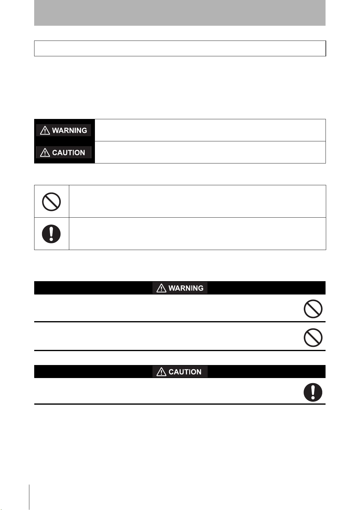
The OS32C uses a beam report selection mask to select the areas of interest. When defining the
required resolution and selected zones of interest, the beam report selection mask provides the
greatest flexibility for changing monitored zones during run-time. Figure 4-1 below shows the coverage
area when all beams are selected and each bit in the beam report selection mask is set to 1. Two
additional beams before and after the sensing field are provided to ensure the full safety region is
protected at all times. Therefore the true monitoring region coverage is from -0.4° to 270.4°.
Description Enumeration / Possible Values
Data Type: UINT
16-bit
Not used.
16
OS32C with EtherNet/IP & Measurement Data Addendum
Page 24
EtherNet/IP Input Assembly Data
-0.4° to 270.4°
Beam 0 thru 676
0.4° per beam
135º
0º
270º
135º
0º
270º
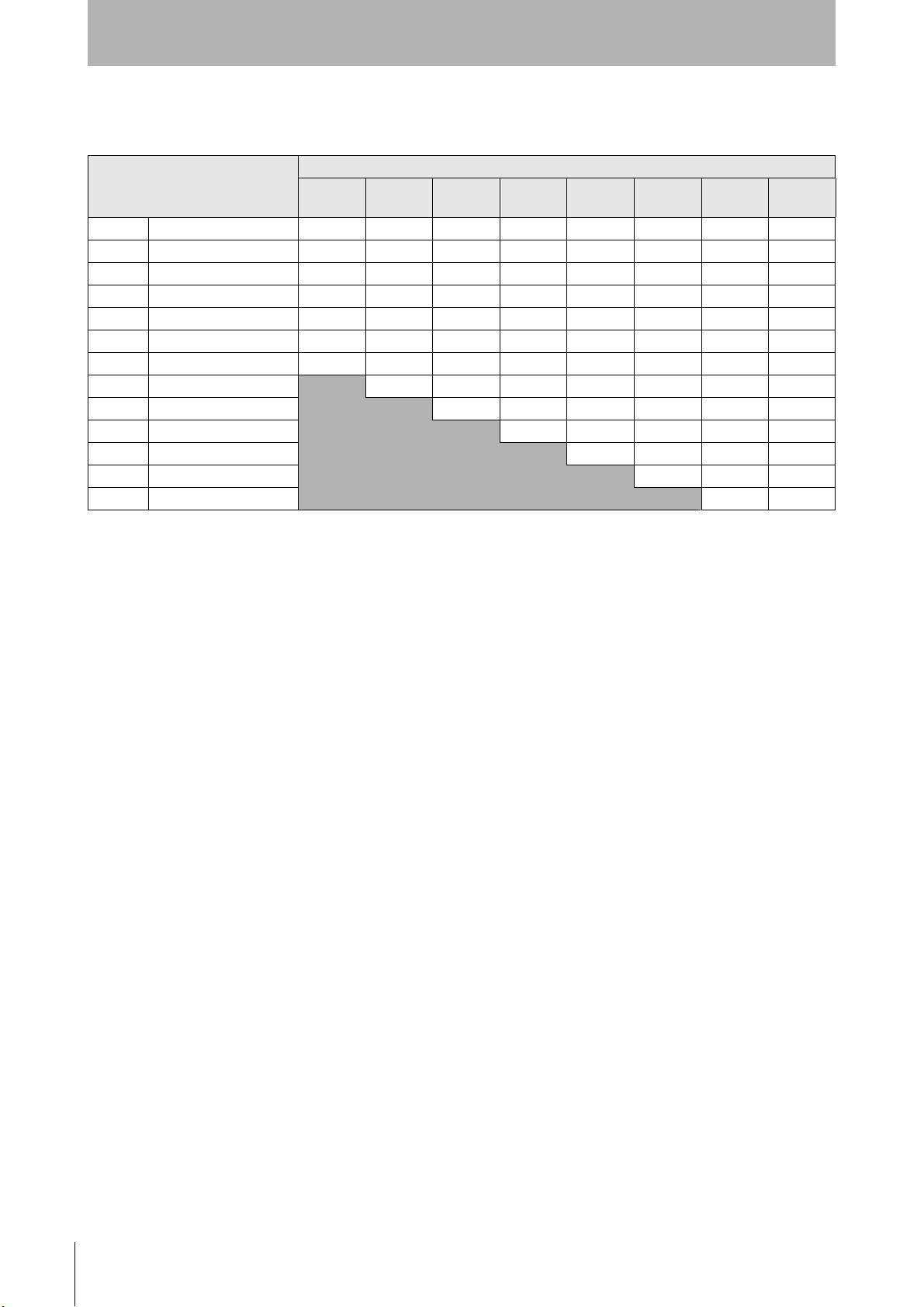
90° to 180°,
Beam 225 thru 450
0.4° per beam
135º
0º
270º
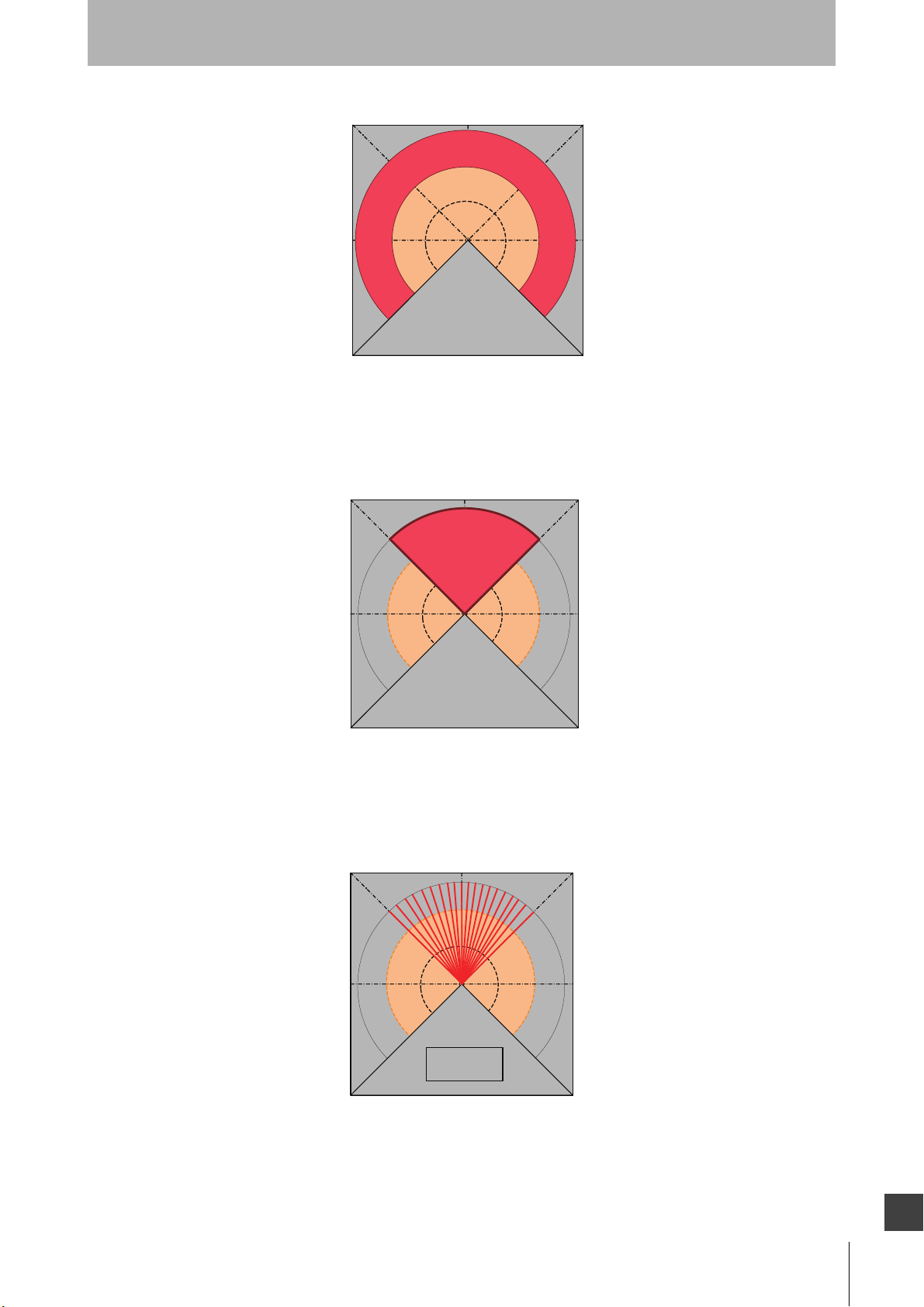
90° to 180°,
Beam 225 thru 450
2.0° per beam
Fig. 4-1 Beam Report Selection Mask, All Beams
Using the OS32C beam report selection mask smaller areas of interest can also be defined. For
example setting the selection bits 225 thru 450 in the beam report selection mask provides an area of
coverage from 90 to 180 degrees in the scan plane.
Introduction
Fig. 4-2 Beam Report Selection Mask, Beam 225 through 450
As shown in Figure 4-3 below, the beam report selection mask can also be used to reduce the amount
of data provided in the area of interest. For example setting every 5th beam in the selection bits 225
through 450 in the selection mask provides an area of coverage with a resolution of 2 degrees.
Fig. 4-3 Beam Report Selection Mask, Beam 225 through 450 with Low Resolution
OS32C with EtherNet/IP & Measurement Data Addendum
E
17
Page 25

Introduction
EtherNet/IP Input Assembly Data
Input assembly objects 102 through 105 as well as vendor specific objects 114, 116 and 117 provide a
common measurement report header format in addition to the specific measurement data provided in
these assembly structures. Table 8 below shows the common measurement report header format.
Using explicit TCP/IP request/reply messages or an implicit UDP I/O connection for assembly objects
102 through 105 the scanner can be monitored at a repetition rate defined for the application.
4.8 Table 8: Common Measurement Report Header Format (56 bytes)
Word #
(16-bit)
0 & 1
2 & 3
4 & 5
6 & 7
8
9
10
11
Description
Scan Count
Data Type: UDINT
32-bit
Scan Rate
Data Type: UDINT
32-bit
Scan Time Stamp
Data Type: UDINT
32-bit
Scan Beam Period
Data Type: UDINT
32-bit
Machine State
Data Type: UINT
16-bit
Machine Stop
Reasons
Data Type: UINT
16-bit
Active Protection
Zone Set
Data Type: UINT
16-bit
Zone Inputs
Data Type: WORD
16-bit
Vendor Specific
Object x, Instance
y, Attribute
Number z
0x72, 1, 13 (0x0D)
0x72, 1, 14 (0x0E)
0x72, 1, 15 (0x0F)
0x72, 1, 16 (0x10)
0x70, 1, 4
0x70, 1, 5
0x70, 1, 6
0x70, 1, 7
Enumeration / Possible Values
0 to 4294967295 (2
39,000 us ± 500 us
0 to 4294967295 (2
42,777 to 43,888 ns
POST = 0 // Power-on-self-test
STOP = 1 // Machine Stop, Protection Zone Violation
INTERLOCK = 2 // Start Interlock
RUN = 3 // Machine Run
STANDBY = 4 // System Standby.
CONFIGURE = 6 // Configuration process in session.
FAULT = 7 // System Faulted, OSSD's are OFF.
DIRTY_WINDOW = 0 // Dirty window cause system to stop.
ZONE_SELECT_NUM_ACTIVE = 1 // Invalid zone inputs, with wrong number
of active inputs.
ZONE_SELECT_INVALID = 2 // Invalid zone inputs, with correct
number of active inputs.
QUALIFIED_ZONE_VIOLATION = 3 // Qualified protection zone violation.
STAND_BY_REQUEST = 4 // Stand-by requested.
RX_ERROR = 5 // Receiver error
TOO_CLEAN_WINDOW = 6 // Too clean window caused system to
stop.
NOT IN MACHINE STOP_1 = 7 // System currently not in stop mode
SYSTEM FAULTED = 8 // The system faulted, check display
code
NOT IN MACHINE STOP_2 = 9 // System currently not in stop mode
AZS_01 = 0 (0x00)
...
AZS_70 = 69 (0x45)
INVALID AZS = 32,768 (0x8000)
Zinput 1 = bit 0
Zinput 2 = bit 1
Zinput 3 = bit 2
Zinput 4 = bit 3
Zinput 5 = bit 4
Zinput 6 = bit 5
Zinput 7 = bit 6
Zinput 8 = bit 7
32
32
)
) us
18
OS32C with EtherNet/IP & Measurement Data Addendum
Page 26

EtherNet/IP Input Assembly Data
Introduction
Word #
(16-bit)
12
13
14
15
16
17
18
19 Unused For future use.
20 Unused For future use.
21 Unused For future use.
22 Unused For future use.
23 Unused For future use.
24
25
26
27 Number of Beams 0x72, 1, 17 (0x11) Number of measurement beams in report.
Description
Detection Zone
Status
Data Type: WORD
16-bit
Output Status
Data Type: WORD
16-bit
Input Status
Data Type: WORD
16-bit
Seven Segment
Display
Data Type: UINT
16-bit
Non-Safety
Configuration
Checksum Value
Data Type: UINT
16-bit
Safety
Configuration
Checksum Value
Data Type: UINT
16-bit
Active Warning
Zone Set
Data Type : UINT
16-bit
Range Report
Format
Data Type: UINT
16-bit
Reflectivity Report
Format
Data Type: UINT
16-bit
Range Report
Mode
Data Type : UINT
16-bit
Vendor Specific
Object x, Instance
y, Attribute
Number z
0x70, 1, 8
0x70, 1, 9
0x70, 1, 10 (0x0A)
0x70, 1, 11 (0x0B)
0x70, 1, 12 (0x0C)
0x70, 1, 13 (0x0D)
0x70, 1, 14 (0x0E)
0x72, 1, 4
0x72, 1, 5
0x72, 1, 6 (0x06)
Enumeration / Possible Values
Protection Zone = bit 0
Warning Zone #1 = bit 1
Warning Zone #2 = bit 2
Window Contamination = bit 3
OSSD Output = bit 0
Auxiliary Output = bit 1
Warning Output = bit 2
StandBy Input = bit 0
Start Input = bit 1
EDM Input = bit 2
Digit Low followed by Digit High
Each Digit Displays 1 to 9 (0x01 to 0x09) for normal operation.
0x1B and 0x1B for dashes "--" during machine stop operation.
16-bit Non-Safety Configuration CRC Value
16-bit Safety Configuration CRC Value
AZS_01 = 0 (0x00)
…
AZS_70 = 69 (0x45)
INVALID AZS = 32,768 (0x8000)
Report format of range data
Report format of reflectivity data
REPORT_RANGE_ONLY = 0 (default),
// Assembly 102 Report Range Only.
REPORT_RANGE_AND_REFLECTIVITY = 1, // Assembly 102 Report Range &
Reflectivity.
OS32C with EtherNet/IP & Measurement Data Addendum
E
19
Page 27

Introduction
EtherNet/IP Input Assembly Data
In addition to the common measurement report header defined in Table 8, Input Assembly 102 and
Vendor Specific Object 114 includes range measurement data for the selected area of interest. Using
explicit TCP/IP request/reply messages or an implicit UDP I/O connection the scanner can be
monitored at a repetition rate defined for the application.
4.9 Table 9: Input Assembly 102 and Vendor Specific Object 114 (max.
1410 bytes)
Range measurement data, variable size.
Size selected using the beam report mask configuration. (1)
Array Size = Number of Beams included in measurement report header,
maximum size = 677.
28 - 704
Range (TOF)
data[]
UINT 16-bit
In addition to the common measurement report header defined in Table 8, Input Assembly 103
includes reflectivity measurement data for the selected area of interest. Using explicit TCP/IP request/
reply messages or an implicit UDP I/O connection the scanner can be monitored at a repetition rate
defined for the application.
4.10 Table 10: Input Assembly 103 and Vendor Specific Object 116 (max.
1410 bytes)
Reflectivity (TOT)
28 - 704
data[]
UINT 16-bit
In addition to the common measurement report header defined in Table 8, Vendor Specific Object 117
includes both range and reflectivity measurement data for the selected area of interest. Since UDP I/O
messages are limited to less than 1500 bytes this assembly can only be provided using explicit TCP/IP
request/reply messages. The scanner will respond to each request immediately after the next scan
period.
Reflectivity measurement data, variable size.
Size selected using the beam report mask configuration. (1)
Array Size = Number of Beams included in measurement report header,
maximum size = 677.
20
4.11 Table 11: Vendor Specific Object 117 (max. 2764 bytes)
Range (TOF)
28 - 704
705-1381
Note *1. See section Table 4: Output Assembly 113 and Vendor Object 115 (104 bytes), Measurement Report Configuration for Input
Assembly 102 & 103 for beam selection mask usage.
*2. Vendor Specific Assembly reports are synchronous with the scan period of the scanner.
data[]
UINT 16-bit
Reflectivity (TOT)
data[]
UINT 16-bit
OS32C with EtherNet/IP & Measurement Data Addendum
Range measurement data, variable size.
Size selected using the beam report mask configuration. *1. *2.
Array Size = Number of Beams included in measurement report header,
maximum size = 677.
Reflectivity measurement data, variable size.
Size selected using the beam report mask configuration. *1. *2.
Array Size = Number of Beams included in measurement report header,
maximum size = 677.
Page 28

EtherNet/IP Input Assembly Data
In addition to the common measurement report header defined in Table 8, Input Assembly 104
includes range measurement data for the selected area of interest. Using explicit TCP/IP request/reply
messages or an implicit UDP I/O connection the scanner can be monitored at a repetition rate defined
for the application.
4.12 Table 12: Input Assembly 104 (max. 960 bytes)
Introduction
Range (TOF)
28 - 479
* See Table 5: Output Assembly 114 (108 bytes), Measurement Report Configuration for Input Assembly 104 & 105 for beam selection
mask usage.
data[]
UINT 16-bit
Range measurement data, variable size.
Size selected using the beam report mask configuration. *
Array Size = Number of Beams included in measurement report header,
maximum size = 452 without tags.
In addition to the common measurement report header defined in Table 8, Input Assembly 105
includes reflectivity measurement data for the selected area of interest. Using explicit TCP/IP request/
reply messages or an implicit UDP I/O connection the scanner can be monitored at a repetition rate
defined for the application.
4.13 Table 13: Input Assembly 105 (max. 960 bytes)
Reflectivity (TOT)
28 - 479
* See Table 5: Output Assembly 114 (108 bytes), Measurement Report Configuration for Input Assembly 104 & 105 for beam selection
mask usage.
data[]
UINT 16-bit
Input Assembly 106 includes range measurement data for the selected area of interest. Using explicit
TCP/IP request/reply messages or an implicit UDP I/O connection the scanner can be monitored at a
repetition rate defined for the application.
Reflectivity measurement data, variable size.
Size selected using the beam report mask configuration. *
Array Size = Number of Beams included in measurement report header,
maximum size =452 without tags.
4.14 Table 14: Input Assembly 106 (max. 554 bytes)
Range (TOF)
0 - 276
* See Table 6 : Output Assembly 115 (316 bytes), Measurement Report Configuration for Input Assembly 106 through 111
data[]
UINT 16-bit
Input Assembly 107 includes reflectivity measurement data for the selected area of interest. Using
explicit TCP/IP request/reply messages or an implicit UDP I/O connection the scanner can be
monitored at a repetition rate defined for the application.
Range measurement data, variable size.
Size selected using the beam report mask configuration. *
Array Size = Number of Beams included in measurement report header,
maximum size = 277 without tags.
4.15 Table 15: Input Assembly 107 (max. 554 bytes)
Reflectivity measurement data, variable size.
Reflectivity (TOT)
0 - 276
* See Table 6 : Output Assembly 115 (316 bytes), Measurement Report Configuration for Input Assembly 106 through 111
data[]
UINT 16-bit
Size selected using the beam report mask configuration. *
Array Size = Number of Beams included in measurement report header,
maximum size =277 without tags.
OS32C with EtherNet/IP & Measurement Data Addendum
E
21
Page 29

Introduction
EtherNet/IP Input Assembly Data
Input Assembly 108 includes range measurement data for the selected area of interest. Using explicit
TCP/IP request/reply messages or an implicit UDP I/O connection the scanner can be monitored at a
repetition rate defined for the application.
4.16 Table 16: Input Assembly 108 (max. 454 bytes)
Range (TOF)
0 - 226
* See Table 6 : Output Assembly 115 (316 bytes), Measurement Report Configuration for Input Assembly 106 through 111
data[]
UINT 16-bit
Range measurement data, variable size.
Size selected using the beam report mask configuration. *
Array Size = Number of Beams included in measurement report header,
maximum size = 227 without tags.
Input Assembly 109 includes reflectivity measurement data for the selected area of interest. Using
explicit TCP/IP request/reply messages or an implicit UDP I/O connection the scanner can be
monitored at a repetition rate defined for the application.
4.17 Table 17: Input Assembly 109 (max. 454 bytes)
Reflectivity (TOT)
0 - 226
* See Table 6 : Output Assembly 115 (316 bytes), Measurement Report Configuration for Input Assembly 106 through 111
data[]
UINT 16-bit
Input Assembly 110 includes range measurement data for the selected area of interest. Using explicit
TCP/IP request/reply messages or an implicit UDP I/O connection the scanner can be monitored at a
repetition rate defined for the application.
Reflectivity measurement data, variable size.
Size selected using the beam report mask configuration. *
Array Size = Number of Beams included in measurement report header,
maximum size =227 without tags.
4.18 Table 18: Input Assembly 110 (max. 358 bytes)
Range (TOF)
0 -178
* See Table 6 : Output Assembly 115 (316 bytes), Measurement Report Configuration for Input Assembly 106 through 111
data[]
UINT 16-bit
Range measurement data, variable size.
Size selected using the beam report mask configuration. *
Array Size = Number of Beams included in measurement report header,
maximum size = 179 without tags.
Input Assembly 111 includes reflectivity measurement data for the selected area of interest. Using
explicit TCP/IP request/reply messages or an implicit UDP I/O connection the scanner can be
monitored at a repetition rate defined for the application.
4.19 Table 19: Input Assembly 111 (max. 358 bytes)
Reflectivity (TOT)
0 - 178
* See Table 6 : Output Assembly 115 (316 bytes), Measurement Report Configuration for Input Assembly 106 through 111
data[]
UINT 16-bit
Reflectivity measurement data, variable size.
Size selected using the beam report mask configuration. *
Array Size = Number of Beams included in measurement report header,
maximum size =179 without tags.
4.20 Data Refresh Rate (Expected Packet Rate)
The data refresh rate for the scanner is approximately 40 (38.5 to 39.5) milliseconds. When configuring
the scanner on an EtherNet/IP PLC network it is recommended to set the expected packet rate for the
input assembly data to a value of 50 milliseconds or more.
22
OS32C with EtherNet/IP & Measurement Data Addendum
Page 30

4.21 Active Warning Zone Set Selection
When the scanners "Monitoring zone" is configured for multiple detection zone sets and the "Warning
zone selection by EIP" is enabled, the EtherNet/IP interface can be used to change the active warning
zone set instead of using the zone inputs. When this feature is enabled an EtherNet/IP network device
must select one of the 70 possible preprogrammed warning zone sets before starting normal
operation. For more information on zone configuration and selection, see sections "Zone Set Selection
and Configuration" and "Zone Set Input Selection" in the OS32C user manual. The switching time of
the active warning zone set using the EtherNet/IP interface is one scan cycle or approximately 40
milliseconds. Output assembly objects 113, 114, 115 each can be used to define the active warning
zone set as well as the vendor specific object 115 listed in Table 4.
EtherNet/IP Input Assembly Data
Introduction
OS32C with EtherNet/IP & Measurement Data Addendum
E
23
Page 31

Introduction
Installing the OS32C EDS file
5. Installing the OS32C EDS file
The EDS file for the OS32C can be found on the OS32C Configuration Tool CD that is shipped with the
scanner.
To install the EDS file in Omron's Network Configurator software:
From the EDS File menu, select Install.
Fig. 5-1 Install EDS File
When prompted, locate the EDS file then click OK. The OS32C will now appear in the hardware list on the left
side of the Network Configurator window.
24
OS32C with EtherNet/IP & Measurement Data Addendum
Page 32

Establishing a connection with Omron CJ2
6. Establishing a connection with Omron CJ2
This section provides step by step instructions for setting up communication from the OS32C to Omron's CJ2
(or CJ1) PLC via EtherNet/IP.
6.1 Setting up the EtherNet/IP Network
Start up Network Configurator and create a new EtherNet/IP network.
Drag and drop the OS32C and the CJ2B-EIP21 from the hardware list onto the EtherNet/IP network in
Network Configurator.
Introduction
Fig. 6-1 Select Devices from Hardware List
Make sure the IP addresses match the IP address of the respective devices. To change the IP address
of the device, right click on the device icon and select Change Node Address.
Fig. 6-2 Change Node Address
In this example, the OS32C has an IP address of 192.168.250.1 and the CJ2 has an IP address of
192.168.250.2
6.2 Setting up EtherNet/IP Tags for the CJ2
Double-click the CJ2B-EIP21 icon and select the Tag Sets tab, select the In-Consume tab, then click
the Edit Tags button.
OS32C with EtherNet/IP & Measurement Data Addendum
E
25
Page 33

Introduction
Establishing a connection with Omron CJ2
Fig. 6-3 Edit Tags
Select the In-Consume tab then click New to create a new tag:
Fig. 6-4 Create New Tag
For the Name field, enter the memory location in the PLC where the OS32C data will be written to. For
this example, enter D0 for the name to specify the DM memory area 0 of the CJ2.
NOTE: upper case letters must be used when specifying these memory area. In this case, enter “D0”
exactly as shown. A lower case “d” will not work.
Enter 32 bytes for the size field. When done, click the Regist button, then the Close button.
Fig. 6-5 Register Tag
26
OS32C with EtherNet/IP & Measurement Data Addendum
Page 34

Establishing a connection with Omron CJ2
Select the Out-Produce tab then click New to create a new tag:
Fig. 6-6 Create New Tag
Enter D100 for the name to specify DM memory area 100 of the CJ2. Reminder: the D in D100 must
be upper case. Enter 2 bytes for the size. When done, click the Regist button, then the Close button.
Introduction
Fig. 6-7 Register Tag
Click OK to complete the creation of the tags.
Fig. 6-8 Click OK
When prompted, click Yes to register the new Tags as Tag Sets:
OS32C with EtherNet/IP & Measurement Data Addendum
E
27
Page 35

Introduction
Establishing a connection with Omron CJ2
Fig. 6-9 Register Tag Sets
Select the Connections tab, highlight the OS32C, then click the down arrow to register the OS32C as
a slave device to the CJ2:
Fig. 6-10 Register OS32C to CJ2
Once the OS32C is listed under the Register Device List, double-click on the OS32C to edit the
connection. Under the Originator Device, select the input and output tag sets that were just created, so
that it matches the screenshot below.
28
OS32C with EtherNet/IP & Measurement Data Addendum
Page 36

Establishing a connection with Omron CJ2
Introduction
Fig. 6-11 Edit Connection Window
Click the Show Detail button in the lower left hand corner of this window. Set the RPI to 200 ms. Click
the Regist button when finished then click Close.
Fig. 6-12 Packet Interval Setting
Click OK in the Edit Device Parameters window:
OS32C with EtherNet/IP & Measurement Data Addendum
E
29
Page 37

Introduction
Establishing a connection with Omron CJ2
Fig. 6-13 OS32C Is Registered
6.3 Downloading EtherNet/IP Configuration to the CJ2
Now that the Tags have been set up, the EtherNet/IP configuration needs to be downloaded to the
CJ2. Connect the computer to the CJ2 via USB cable.
In the Network Configurator, go to the Option menu, choose Select Interface, then select CJ2 USB/
Serial Port.
Fig. 6-14 Select Interface
From the Network menu, select Connect.
Select TCP:2, then click OK to connect.
30
Fig. 6-15 Select Network Port
Right click on the CJ2B icon, select Parameter, then select Download.
OS32C with EtherNet/IP & Measurement Data Addendum
Page 38

Establishing a connection with Omron CJ2
Fig. 6-16 Download to Device
To download to the CJ2 module without changing the PLC to Program mode, click Download with
Current Mode when prompted:
Introduction
Fig. 6-17 Download with Current Mode
OS32C with EtherNet/IP & Measurement Data Addendum
E
31
Page 39

Introduction
Establishing a connection with Omron NJ
7. Establishing a connection with Omron NJ
This section provides step by step instructions for setting up communication from the OS32C to Omron's NJ5
PLC using EtherNet/IP communications.
7.1 NJ5 MAC EtherNet/IP Adapter Setup
Open the Sysmac Studio programming software and either open the project associated with the
machine or create a new one. Double click on the Built-in EtherNet/IP Port Setting option under
Configurations and Setup as shown below:
Fig. 7-1 Built-in EtherNet/IP Port Setting
In the window that appears, make the appropriate IP address setting to the NJ. In this example the NJ
will be set to 192.168.250.2 and the OS32C will be set to 192.168.250.7
Fig. 7-2 IP Address Setting
7.2 Setting up tags in the NJ Controller
32
The NJ supports tag based I/O structures and these tags need to be generated in order for the OS32C
to communicate correctly with the NJ controller via EtherNet/IP.
Under the Programming tab in the menu tab select Data and then Data Types.
OS32C with EtherNet/IP & Measurement Data Addendum
Page 40

Establishing a connection with Omron NJ
Fig. 7-3 Data Types
In the window that appears, right click on "Name" and select Create New Data Type.
Introduction
Fig. 7-4 Create New Data Type
Two new data types will need to be created, "OS32C_Scanner_IN" and "OS32C_Scanner_OUT",
along with the Base Type "STRUCT". The tags will look like the following screenshot:
Fig. 7-5 OS32C IN and OUT Structure Data Types
Once the base tag has been created, assembly I/O data needs to be added to each tag. Right click on
the tag name and select Create New Member. Repeat this until all I/O data is created as shown in the
figure below:
OS32C with EtherNet/IP & Measurement Data Addendum
E
33
Page 41

Introduction
Establishing a connection with Omron NJ
Fig. 7-6 OS32C IN and OUT Structure Members
7.3 Setting Tags into Global Variable Section
Once the OS32C EtherNet/IP tags and I/O data have been created in the NJ, a global variable will
have to be generated for every laser scanner that the NJ will establish EtherNet/IP communications
with.
Click on the Global Variables option in the project work space. Right click in the global variable
window and select Create New and a new variable will be created.
Fig. 7-7 Global Variables
Fig. 7-8 Create New Global Variable
34
Give the variable a name and choose the structure name from the variable type. It is also necessary to
define the tag as an input or output on the network. This will need to be done once for the produced
variable and once for the consumed variable.
OS32C with EtherNet/IP & Measurement Data Addendum
Page 42

Establishing a connection with Omron NJ
The OS32C produced and consumed tags are shown below:
Fig. 7-9 OS32C Produced and Consumed Tags
Notice that the OS32C produced information is named as an input for the tag creation. This is because
when the OS32C produces data, it is consumed by the NJ5. Therefore, it acts like as an input to the
NJ5. The OS32C consumed information is produced (or output) by the NJ5, so the network publish
type is set to output.
7.4 Exporting Tags to Network Configurator
The tags that have been created in the NJ can now be exported to be used by the Network
Configurator software. Doing this will ensure the tag I/O structure will match.
Under the Tools menu in the main window select Export Global Variables then select Network
Configurator:
Introduction
Fig. 7-10 Export Global Variables
This will save the data in an Excel spreadsheet as a .csv file to be imported by the Network
Configurator software.
7.5 Configuring the EtherNet/IP Network
To configure the Ethernet /IP connection to the NJ, start up the Network Configurator software and
create a new EtherNet/IP program.
Drag and drop the NJ5 and the OS32C from the hardware list onto the EtherNet/IP network in the
Network Configurator. Ensure the IP addresses match the hardware IP settings.
Fig. 7-11 Add NJ5 and OS32C to the EtherNet/IP Network
Double click on the NJ5 and select the Tag Sets tab. Click the To/From button and select Import
From File.
OS32C with EtherNet/IP & Measurement Data Addendum
E
35
Page 43

Introduction
Establishing a connection with Omron NJ
Fig. 7-12 Import Tag Sets from File
Browse to the .csv file that contains the network tags that were exported from Sysmac Studio, select it
and press OK. When prompted, click Yes to import the symbols. The tags will now appear on the In-
Consume and Out-Produce tabs. When complete, the In - Consume and Out - Produce tabs will
appear as follows:
Fig. 7-13 In - Consume Tab
Fig. 7-14 Out - Produce Tab
Select the Connections tab. The OS32C module will appear under the list of unregistered devices.
Select OS32C module and press the down arrow to move the OS32C from the unregistered device
list to the registered device list.
Once the OS32C is shown in the registered device list, double click on the OS32C which will bring up
an Edit Connection window. Match the tag names on the left hand side up with the input and the output
assemblies on the right hand side. In this example, only one tag will be in the list for each of the
connections. Use 200 for the RPI value. When done, the settings will look like the screenshot below.
36
OS32C with EtherNet/IP & Measurement Data Addendum
Page 44

Establishing a connection with Omron NJ
Introduction
Fig. 7-15 Edit Connection Window
Press the Regist button at the bottom of the window then press the Close button. Lastly, click OK on
the Edit Device Parameters page.
The network will now look like the screenshot shown below. The arrow (highlighted in the red box)
shows that the node is now registered to the NJ5.
Fig. 7-16 OS32C Is Registered to NJ5
7.6 Downloading EtherNet/IP Configuration to the NJ
Connect the NJ5 to the computer using the USB cable.
In the Network Configurator software, choose the Option pull-down menu then choose Select
Interface, then choose NJ Series USB Port.
From the Network menu, select Connect.
Click on TCP:2 and then press OK.
OS32C with EtherNet/IP & Measurement Data Addendum
E
37
Page 45

Introduction
Establishing a connection with Omron NJ
Fig. 7-17 Select Network Port
Select Use the existing network, and click OK.
Fig. 7-18 Use Existing Network
Right-click the NJ5 icon, select Parameter, then choose Download.
Fig. 7-19 Download to NJ5
To download to the NJ5 without changing the PLC to Program mode, click Download with Current
Mode.
38
OS32C with EtherNet/IP & Measurement Data Addendum
Page 46

Establishing a connection with Omron NJ
Fig. 7-20 Download with Current Mode
When the download is complete, click OK. Setup is now complete.
Introduction
OS32C with EtherNet/IP & Measurement Data Addendum
E
39
Page 47

Introduction
Setup for multiple OS32Cs or multiple PLCs
8. Setup for multiple OS32Cs or multiple PLCs
The OS32C with EtherNet/IP can be polled in a few different ways. The laser scanner can have multiple
EtherNet/IP master devices polling it for information or one EtherNet/IP master can be set up to poll multiple
scanners.
8.1 One PLC Polling Multiple OS32Cs
One master device can poll multiple laser scanners on the network.
Open Network Configurator and add the number of needed scanners to the EtherNet/IP network. For
this example there are three OS32Cs and a CJ2 PLC.
Fig. 8-1 One PLC with Multiple OS32Cs
Double-click the CJ1W-EIP21 icon and select the Tag Sets tab, select the In-Consume tab, then click
the Edit Tags button.
40
Fig. 8-2 Edit Tags
OS32C with EtherNet/IP & Measurement Data Addendum
Page 48

Setup for multiple OS32Cs or multiple PLCs
Enter D0 for name, this field will determine the memory location written to in the PLC. In the size field
enter 32 bytes, this number needs to match the number of Target Input bytes on the OS32C. This step
will need to be repeated for the number of scanners to be registered to this master. Make sure the
memory locations do not overlap.
Fig. 8-3 Create Input Tags
Introduction
Click Regist to create the tag. Repeat this for every laser scanner.
Select the Out-Produce tab then Click New to create a new tag.
Enter D100 for name, this field will determine the memory location written to in the PLC. D100 would
be location DM100 in the PLC. The size field needs to be 2 bytes as this number has to match the
number of Target Out p u t bytes on the OS32C.
Fig. 8-4 Create Output Tags
Click Regist to create the tag.
When all tags have been created the tag window should look like this:
Fig. 8-5 Completed Output Tags
OS32C with EtherNet/IP & Measurement Data Addendum
E
41
Page 49

Introduction
Setup for multiple OS32Cs or multiple PLCs
Select the Connections tab, highlight the OS32C and click the Down Arrow as shown below to move
the device from the unregistered device list to the registered device list. Repeat for all scanners that
will be slaves to this master.
Fig. 8-6 Register Each OS32C to PLC
Double click on the scanner in the registered device window to configure each scanner's I/O location in
the PLC. Notice that there will be three different Input and Output Tags to choose from. Select the DM
location in the PLC where the data from the scanner will be written to. This step is needed for every
scanner.
42
Fig. 8-7 Edit Connection Window
OS32C with EtherNet/IP & Measurement Data Addendum
Page 50

Setup for multiple OS32Cs or multiple PLCs
When all scanners have been configured the screen should look like the following figure:
Introduction
Fig. 8-8 All Scanners Configured
All three laser scanners are now registered to the CJ2:
Fig. 8-9 Registration Complete
8.2 Multiple PLCs Polling One OS32C
The setup for multiple devices polling a single OS32C is very similar to the setup for one device polling
multiple scanners. The key point with this type of configuration is only one device can be the
Exclusive Owner of the scanner while all other master devices need to be configured as Listen only
or Input Only.
Input Only Example
OS32C with EtherNet/IP & Measurement Data Addendum
E
43
Page 51

Introduction
Setup for multiple OS32Cs or multiple PLCs
Listen Only Example
Fig. 8-10 Input Only Example
44
Fig. 8-11 Listen Only Example
Both of these methods work for this type of configuration but note the differences between these two
options that should be taken in account:
1. Input Only: This type of configuration will generate a message to poll the scanner as the RPI set
rate, this may be an issue if too many devices are requesting data from the scanner.
OS32C with EtherNet/IP & Measurement Data Addendum
Page 52

Setup for multiple OS32Cs or multiple PLCs
2. Listen Only: This type of configuration will only listen to messages generated by a master on the
network; it will not generate its own. This is good to limit generated messages on the network but if
the master device stops polling the sensor all other devices will stop as well.
Introduction
OS32C with EtherNet/IP & Measurement Data Addendum
E
45
Page 53

Introduction
Establishing communications with a computer based device
9. Establishing communications with a computer based
device
This section provides general information for setting up communication connections between the OS32C and
a computer based device. This section provides information from the EtherNet/IP specification necessary to
communicate with the OS32C within a single EtherNet/IP subnet/network. When used in a standard Ethernet
network, communications across subnet/networks is also possible using the communication formats provided
in this manual.
9.1 EtherNet/IP Command Protocol
All electronic datagram command payloads contain a fixed-length header of 24-bytes followed by an
optional data portion. The total datagram payload length is limited to 65535 bytes for TCP/IP
messages and 1500 bytes for UDP/IP messages. Table 10 below outlines the basic structure for
EtherNet/IP commands.
9.1.1 Table 10: EtherNet/IP Datagram Header - Command Format
Structure Field Name Data Type Data Size Field Value
Encapsulation
Header
Command specific
data
Command UINT 2 bytes Encapsulation command number.
Length UINT 2 bytes Length, in bytes, of the command specific data
portion of the message following the encapsulation
header.
Session Handle ID UDINT 4 bytes Session identification used for configuration and
run-time monitoring.
Status UDINT 4 bytes Status code used in reply messages.
Sender Context
Data
Command options UDINT 4 bytes Optional command flags.
Command data ARRAY of 0 to
ARRAY of 8 octets 8 bytes Information pertinent only to the sender of an
encapsulation command.
0 to 65511 bytes The encapsulation data portion of the message is
65511 octets
required only for certain commands.
9.2 EtherNet/IP Command List
EtherNet/IP provides fundamental commands for accessing all scanner data as outlined in Table 11
below.
46
9.2.1 Table 11: EtherNet/IP Command List
Command Name Command Code Description
NOP 0x0000 A non-operational command used during TCP communications to verify TCP
connections (may be sent only using TCP).
List Services 0x0004 List the scanners EtherNet/IP services available (may be sent using either UDP or
TCP).
List Identity 0x0063 List the scanners EtherNet/IP identity, vendor ID, device ID, serial number and other
information (may be sent using either UDP or TCP).
List Interfaces 0x0064 List the scanners EtherNet/IP assembly and input/output object interfaces available
(may be sent using either UDP or TCP).
Register Session 0x0065 Open and register a communication session with the scanner (may be sent only using
TCP).
OS32C with EtherNet/IP & Measurement Data Addendum
Page 54

Establishing communications with a computer based device
Command Name Command Code Description
Un-Register Session 0x0066 Close the registered communication session with the scanner (may be sent only using
TCP).
SendRRData 0x006F Send a request/reply command to the scanner along with a sub-command and optional
data (may be sent only using TCP).
If the command requests are successfully registered with the scanner, the Status field shall be zero (0).
If the command requests are not successfully registered, the Status field shall contain the one of the
following error codes.
9.2.2 Table 12: EtherNet/IP Status Error Code List
Error Codes Description
0x0000 No error in command request.
0x0001 Invalid command used in request.
0x0002 Insufficient memory in target device.
0x0003 Incorrect data used in request.
0x0064 Invalid session handle used in request.
0x0065 Invalid command length used in request.
0x0069 Unsupported Protocol Version used in request.
Introduction
9.3 EtherNet/IP Command Specific Data
Command specific data provided by the scanner must follow the CIP Common Packet Format as
shown in Table 13 below.
9.3.1 Table 13: EtherNet/IP Common Packet Format (CPF)
Field Name Data Type Description
Item count UINT Number of items to follow
Item #1 Item Structure Field Name Data Type Description 1st Common Packet Format (CPF) item
Type ID UINT Type of item
encapsulated
Length UINT Length in bytes
of the Data
Field
Data Variable The data (if
length >0)
Item #2 Item Structure (see above) 2nd CPF item
------ ------ ------
Item #n Item Structure (see above) nth CPF item
OS32C with EtherNet/IP & Measurement Data Addendum
E
47
Page 55

Introduction
Establishing communications with a computer based device
9.4 EtherNet/IP Commands
9.4.1 List Identity Command
A connection originator may use the List Identity command to locate and identify the scanner. This
command shall be sent as a unicast message using TCP or UDP, or as a broadcast message using
UDP and does not require that a session be established. The reply shall always be sent as a unicast
message.
When received as a broadcast message, the receiving device shall delay for a pseudo-random period
of time prior to sending the reply as specified in section 2-4.2.3 of the EtherNet/IP standard. Delaying
before sending the reply helps to spread out any resulting ARP requests and List Identity replies from
target devices on the network.
9.4.2 Table 14: List Identity Command Request
Datagram Field Name Field Value Data Type Data Size Comments
EtherNet/IP
Header
Command 0x0063 UINT 2 bytes List Identity Command
Length 0 UINT 2 bytes Length of command specific data.
Session
Handle ID
Status 0 UDINT 4 bytes 0
Sender
Context Data
Command
options
Any value UDINT 4 bytes Any value (ignored by target).
UINT 2 bytes Maximum Response Delay in milliseconds.
0 ARRAY[6] 6 bytes Reserved shall be ignored by receiver, values shall
be 0.
0 UDINT 4 bytes 0
9.4.3 Table 15: List Identity Command Reply
Datagram Field Name Field Value Data
Typ e
EtherNet/IP
Header
Command
Specific Data
Command 0x0063 UINT 2 bytes List Identity Command
Length UINT 2 bytes Length of command specific data.
Session Handle
ID
Status 0 UDINT 4 bytes Error status equals 0x0000 if successful.
Sender Context
Data
Command
options
Item Count 1 UINT 2 bytes
Item ID 0x0C UINT 2 bytes CIP Identity Object.
Item Length 2 UINT 2 bytes Number of bytes in item.
ARRAY of octet See Table 16: EtherNet/IP Identity Object Parameters
Array[8] ARRAY
0 UDINT 4 bytes
UDINT 4 bytes Any value (ignored by receiver).
of octet
Data
Size
8 bytes Value from the original request. Length of 8.
Comments
Maximum Response Delay in milliseconds.
48
OS32C with EtherNet/IP & Measurement Data Addendum
Page 56

Establishing communications with a computer based device
9.4.4 Table 16: EtherNet/IP Identity Object Parameters
Parameter Name Data Type Description
Encapsulation Protocol Version UINT Encapsulation Protocol Version supported (also returned with Register Session
reply).
Socket Address Structure of
INT sin_family (big-endian)
UINT sin_port (big-endian)
UDINT sin_addr (big-endian)
ARRAY[8] UINT8 [8] sin_zero (length of 8) (big-endian)
Vendor ID UINT Device manufacturers Vendor ID
Device Type UINT Device Type of product
Product Code UINT Product Code assigned with respect to device type
Revision ARRAY[2] Device revision
Status WORD Current status of device
Serial Number UDINT Serial number of device
Product Name ARRAY[32] Human readable description of device
State UINT8 Current state of device
Introduction
9.4.5 Register Scanner Session Command
The register session procedure is a single step process which only involves obtaining a TCP session
handle from the scanner using the TCP port. Once the session handle is obtained it can be used for all
subsequent TCP and UDP I/O communications. Standard UDP communications using the List Identity
or List Interface commands do not require a session handle.
9.4.5.1 Required Sequence:
• Request a session handle from the scanner using the Register Session command.
9.4.6 Table 17: Register Session Command Request
Datagram part Field Name Field Value Data Type Data Size Comments
EtherNet/IP
Header
Command
Specific Data
Command 0x0065 UINT 2 bytes Request a session handle
Length 4 UINT 2 bytes Length of command specific data.
Session Handle ID 0 UDINT 4 bytes Any value (ignored by scanner)
Status 0 UDINT 4 bytes
Sender Context Data Array[8] ARRAY of
octet
Command options 0 UDINT 4 bytes 0
Protocol Version 1 UINT 2 bytes
Option flags 0 UINT 2 bytes
8 bytes Any value. Length of 8.
9.4.7 Table 18: Register Session Command Reply
Tel egr am-
Datagram part
EtherNet/IP
Header
Field Name Field Value Data Type Data Size Comments
Command 0x0065 UINT 2 bytes Request a session handle
Length 4 UINT 2 bytes Length of command specific data.
OS32C with EtherNet/IP & Measurement Data Addendum
E
49
Page 57

Introduction
Establishing communications with a computer based device
Tel egr am-
Datagram part
Command Specific
Data
Field Name Field Value Data Type Data Size Comments
Session Handle
ID
Status 0 UDINT 4 bytes Error status equals 0x0000 if successful.
Sender Context
Data
Command
options
Protocol Version UINT 2 bytes Version from Register Session request if supported. If
Option flags UINT 2 bytes Option flags from Register Session request if
Array[8] ARRAY of
0 UDINT 4 bytes 0
UDINT 4 bytes Session Handle ID returned by the scanner.
8 bytes Value from request. Length of 8.
octet
the request version is not supported, contains the
highest version supported.
supported. If the request Option flags are not
supported, contains the supported Option flags.
The Session Handle field of the header shall contain a scanner generated identifier that the client
application shall save and insert in the Session Handle field of the header for all subsequent command
requests. This field shall be valid only if the Status field is zero (0). If the client application was
successfully registered with the scanner, the Status field shall be zero (0). If the client application was
not successfully registered, the Status field shall contain the appropriate error code, as follows:
•Error code 0x0001 shall be returned if the client application attempts to register more than 1 active
session on the same TCP connection.
•Error code 0x0002 shall be returned if the scanner does not have sufficient resources to register the
client application.
•Error code 0x0069 shall be returned for Protocol Version or Options mismatches, as described below:
The Protocol Version field shall equal the requested version if the client application was successfully
registered. If the scanner does not support the requested version of the protocol,
•the session shall not be created;
•the Status field shall be set to 'unsupported encapsulation protocol' (0x0069);
•the scanner shall return the highest supported version in the Protocol Version field;
9.4.8 Un-Register Scanner Session Command
Either the client application or the scanner may send this command to terminate the session using the
TCP port. The receiver shall initiate a close of the underlying TCP/IP connection when it receives this
command. The session shall also be terminated when the connection between the client application
and scanner is terminated. The receiver shall perform any other associated cleanup required on its
end. There shall be no reply to this command.
50
9.4.8.1 Required Sequence:
• After a request of a session handle from the scanner using the Register Session command (see
section 9.4.5).
• Logoff the scanner using the current session handle.
OS32C with EtherNet/IP & Measurement Data Addendum
Page 58

Establishing communications with a computer based device
9.4.9 Table 19: Un-Register Session Command Request
Introduction
Tel egramDatagram part
EtherNet/IP
Header
Field Name Field Value Data Type Data Size Comments
Command 0x0066 UINT 2 bytes Terminate the Session.
Length 0 UINT 2 bytes Length of command specific data.
Session Handle ID UDINT 4 bytes Value of current Session Handle ID.
Status 0 UDINT 4 bytes
Sender Context
Data
Command options 0 UDINT 4 bytes 0
Array[8] ARRAY of
The receiver shall not reject the Un-Register Session due to unexpected values in the encapsulation
header (invalid Session Handle, non-zero Status, non-zero Options, or additional command data). In
all cases the TCP connection shall be closed.
9.4.10 SendRRData Command
The SendRRData command is used to send an encapsulated request/reply packet between the
originator and target scanner using the TCP port, where the originator initiates the command. The
actual request/reply packets shall be encapsulated in the data portion of the message and are the
responsibility of the target scanner and originator.
8 bytes Any value. Length of 8 (ignored by scanner).
octet
9.4.11 Table 20: SendRRData Command Request
Datagram Field Name Field Value Data Type Data Size Comments
EtherNet/IP
Header
Command
Specific Data
Command 0x006F UINT 2 bytes SendRRData Command
Length UINT 2 bytes Length of command specific data.
Session Handle
ID
Status 0 UDINT 4 bytes 0
Sender Context
Data
Command
options
Interface Handle ID0 UDINT 4 bytes Interface Handle selected by originator (PLC or PC).
Timeout 0 UINT 2 bytes 0 to 65535 in seconds.
Encapsulation
packet
0 ARRAY[8] 8 bytes Reserved shall be ignored by receiver, values shall be 0.
0 UDINT 4 bytes 0
UDINT 4 bytes Session Handle ID received in the Register Session reply
message.
See Common Packet Format specification in section 9.3
and section 9.4.12 Table 21: Get Single Attribute Service
Code Request CPF Data.
9.4.12 Table 21: Get Single Attribute Service Code Request CPF Data
Field Name Sub-Field Name Field Value Data Type Data Size Comments
Encapsulation packet Item count 2 UINT 2 bytes Number of items to follow
Item #1 / Type ID 0 UINT 2 bytes Address Item Type ID
Item #1 / Length 0 UINT 2 bytes Address Item Length
Item #2 / Type ID 0xB2 UINT 2 bytes Data Item Type ID
Item #2 / Length 8 UINT 2 bytes Data Item Length
OS32C with EtherNet/IP & Measurement Data Addendum
E
51
Page 59

Introduction
Establishing communications with a computer based device
Field Name Sub-Field Name Field Value Data Type Data Size Comments
Data Item 1 Service Code # UINT8 1 byte Get or Set Single Attribute Request
Data Item 2 0x03 UINT8 1 byte Request Path Size in Words
Data Item 3 0x20 UINT8 1 byte Logical Class Type
Data Item 4 Class # UINT8 1 byte Logical Class Number
Data Item 5 0x24 UINT8 1 byte Logical Instance Type
Data Item 6 Instance # UINT8 1 byte Logical Instance Number
Data Item 7 0x30 UINT8 1 byte Logical Attribute Type
Data Item 8 Attribute # UINT8 1 byte Logical Attribute Number
9.4.13 Table 22: SendRRData Command Reply to a Get Single Attribute Request
Datagram Field Name Field Value Data Type Data Size Comments
EtherNet/IP
Header
Command
Specific Data
Encapsulation
Packet
Attribute Data Data Array ARRAY[] Length of
Command 0x006F UINT 2 bytes SendRRData Command
Length UINT 2 bytes Length of command specific data.
Session Handle ID UDINT 4 bytes Session Handle received in the Register Session
reply message.
Status 0 UDINT 4 bytes Error status equals 0x0000 if successful.
Sender Context
Data
Command options 0 UDINT 4 bytes
Interface Handle ID0 UDINT 4 bytes Interface Handle selected by originator (PLC or
Timeout 0 UINT 2 bytes 0 to 65535 in seconds.
Item count 2 UINT 2 bytes Number of items to follow
Item #1 / Type ID 0 UINT 2 bytes Address Item Type ID
Item #1 / Length 0 UINT 2 bytes Address Item Length
Item #2 / Type ID 0xB2 UINT 2 bytes Data Item Type ID
Item #2 / Length 8 + data length UINT 2 bytes Data Item Length
Data Item 1 Response UINT8 1 byte Get or Set Single Attribute Response Code
Reserved field 0 UINT8 1 byte Reserve field not used.
Data Item 2 Status UINT8 1 byte Get or Set Single Attribute error status code.
Data Item 3 Additional
Array[8] ARRAY of
octet
UINT8 1 byte Number of additional error status information in 16-
Status Size
8 bytes Value from request. Length of 8.
PC).
bit words .
Attribute Data if any.
data
52
9.4.14 Table 23: Set Single Attribute Service Code Request CPF Data
Field Name Sub-Field Name Field Value Data Type Data Size Comments
Encapsulation
packet
OS32C with EtherNet/IP & Measurement Data Addendum
Item count 2 UINT 2 bytes Number of items to follow
Item #1 / Type ID 0 UINT 2 bytes Address Item Type ID
Item #1 / Length 0 UINT 2 bytes Address Item Length
Item #2 / Type ID 0xB2 UINT 2 bytes Data Item Type ID
Item #2 / Length 8 + data
length
UINT 2 bytes Data Item Length
Page 60

Establishing communications with a computer based device
Field Name Sub-Field Name Field Value Data Type Data Size Comments
Data Item 1 Service Code #UINT8 1 byte Get or Set Single Attribute Request
Data Item 2 0x03 UINT8 1 byte Request Path Size in Words
Data Item 3 0x20 UINT8 1 byte Logical Class Type
Data Item 4 Class # UINT8 1 byte Logical Class Number
Data Item 5 0x24 UINT8 1 byte Logical Instance Type
Data Item 6 Instance # UINT8 1 byte Logical Instance Number
Data Item 7 0x30 UINT8 1 byte Logical Attribute Type
Data Item 8 Attribute # UINT8 1 byte Logical Attribute Number
Data Array ARRAY[] Length of
attribute data
Attribute Data
9.4.15 Table 24: SendRRData Command Reply to a Set Single Attribute Request
Datagram Field Name Field Value Data Type Data Size Comments
EtherNet/IP
Header
Command
Specific Data
Encapsulation
Packet
Command 0x006F UINT 2 bytes SendRRData Command
Length UINT 2 bytes Length of command specific data.
Session Handle ID UDINT 4 bytes Session Handle received in the Register Session reply
message.
Status 0 UDINT 4 bytes Error status equals 0x0000 if successful.
Sender Context
Data
Command options 0 UDINT 4 bytes
Interface Handle
ID
Timeout 0 UINT 2 bytes 0 to 65535 in seconds.
Item count 2 UINT 2 bytes Number of items to follow
Item #1 / Type ID 0 UINT 2 bytes Address Item Type ID
Item #1 / Length 0 UINT 2 bytes Address Item Length
Item #2 / Type ID 0xB2 UINT 2 bytes Data Item Type ID
Item #2 / Length 8 + data
Data Item 1 Response UINT8 1 byte Get or Set Single Attribute Response Code
Reserved field 0 UINT8 1 byte Reserve field not used.
Data Item 2 Status UINT8 1 byte Get or Set Single Attribute error status code.
Data Item 3 Additional
Array[8] ARRAY of
octet
UDINT 4 bytes Interface Handle selected by originator (PLC or PC).
UINT 2 bytes Data Item Length
length
UINT8 1 byte Number of additional error status information in 16-bit
Status Size
8 bytes Value from request. Length of 8.
words .
Introduction
The SendRRData command is also used to establish a UDP I/O connection between the originating
(PC or PLC) and the target (OS32C) devices. Section 9.4.16 Table 25: Large Forward Open Request
Encapsulation Packet describes the common packet format used along with the SendRRData
command in order to initiate a streaming UDP I/O connection from the OS32C scanner.
OS32C with EtherNet/IP & Measurement Data Addendum
E
53
Page 61

Introduction
Establishing communications with a computer based device
9.4.16 Table 25: Large Forward Open Request Encapsulation Packet
Datagram Field Name Field Value Data Type Data Size Comments
EtherNet/IP
Header
Command
Specific Data
Encapsulation
packet
Command 0x006F UINT 2 bytes SendRRData Command
Length UINT 2 bytes Length of command specific data.
Session Handle ID UDINT 4 bytes Session Handle received in the Register Session reply
message.
Status 0 UDINT 4 bytes Error status equals 0x0000 if successful.
Sender Context
Data
Command options 0 UDINT 4 bytes
Interface Handle
ID
Timeout 0 UINT 2 bytes 0 to 65535 in seconds.
Item count 2 UINT 2 bytes Number of items to follow
Item #1 / Type ID 0 UINT 2 bytes Address Item Type ID
Item #1 / Length 0 UINT 2 bytes Address Item Length
Item #2 / Type ID 0xB2 UINT 2 bytes Data Item Type ID
Item #2 / Length (ex. 54) UINT 2 bytes Data Item Length, length of data to follow below.
Data Item 1 0x5B UINT8 1 byte Large Forward Open Request
Data Item 2 0x02 UINT8 1 byte Request Path Size in Words
Data Item 3 0x20 UINT8 1 byte Logical Class Type
Data Item 4 0x06 UINT8 1 byte Logical Class Request
Data Item 5 0x24 UINT8 1 byte Logical Instance Type
Data Item 6 0x01 UINT8 1 byte Logical Instance Request
Data Item 7 0x06 UINT8 1 byte Priority Time Tick
Data Item 8 (ex. 880) UINT8 1 byte Timeout Ticks (ms)
Data Item 9 0 UDINT 4 bytes O->T identification number
Data Item 10 Any UDINT 4 bytes T->O identification number, use a random number here.
Data Item 11 Any UINT 2 bytes Connection serial number.
Data Item 12 405 UINT 2 bytes Vendor identification number, use of the ORT vendor ID
Data Item 13 Any UDINT 4 bytes Originator serial number
Data Item 14 0 UINT8 1 byte Connection Timeout Multiplier
Data Item 15 0 UINT8 1 byte Reserved
Data Item 16 0 UINT8 1 byte Reserved
Data Item 17 0 UINT8 1 byte Reserved
Data Item 18 Any
Data Item 19 (ex.0x48000
Data Item 20 Any
Data Item 21 (ex.0x48000
Data Item 22 0x01 UINT8 1 byte Transport Class Trigger, Client.
Data Item 23 0x04 UINT8 1 byte Number of words in connection path.
Data Item 24 0x20 UINT8 1 byte Connection path class, instance.
Data Item 25 0x04 UINT8 1 byte Assembly Object connection path logical class.
Array[8] ARRAY of
octet
UDINT 4 bytes Interface Handle selected by originator (PLC or PC).
UDINT 4 bytes O->T repetitive packet interval (RPI) in microseconds
(ex.880000)
UDINT 4 bytes O->T connection parameters.
008)
UDINT 4 bytes T->O repetitive packet interval (RPI) in microseconds
(ex.80000)
UDINT 4 bytes T->O connection parameters.
588)
8 bytes Value from request. Length of 8.
is acceptable here.
(default = 0)
(us).
See EDS file.
(us).
See EDS file.
54
OS32C with EtherNet/IP & Measurement Data Addendum
Page 62

Establishing communications with a computer based device
Datagram Field Name Field Value Data Type Data Size Comments
Data Item 26 0x24 UINT8 1 byte Connection path logical instance segment.
Data Item 27 0x01 UINT8 1 byte Connection path logical instance.
Data Item 28 0x2c UINT8 1 byte Connection point, O->T
Data Item 29 any
(ex. 112)
Data Item 30 0x2c UINT8 1 byte Connection point, T->0
Data Item 31 any
(ex. 102)
UINT8 1 byte Output assembly number
See EDS file.
UINT8 1 byte Input assembly number
See EDS file.
9.4.17 Table 26: SendRRData Command Reply to a Large Forward Open Request
Datagram Field Name Field Value Data Type Data Size Comments
EtherNet/IP
Header
Command
Specific Data
Encapsulation
Data
Command 0x006F UINT 2 bytes SendRRData Command
Length UINT 2 bytes Length of command specific data.
Session Handle ID UDINT 4 bytes Session Handle received in the Register
Session reply message.
Status 0 UDINT 4 bytes 0 if successful.
Sender Context Data Array[8] ARRAY of octet 8 bytes Value from request. Length of 8.
Command options 0 UDINT 4 bytes
Connection Interface
Handle
Timeout Period UINT 2 bytes Connection timeout period to be used in timer.
Item count 4 UINT 2 bytes Number of items to follow.
Item #1 / Type ID 0 UINT 2 bytes Address Item Type ID
Item #1 / Length 0 UINT 2 bytes Address Item Length
Item #2 / Type ID 0xB2 UINT 2 bytes Data Item Type ID
Item #2 / Length Data length UINT 2 bytes Data Item Length, length of data to follow
Data Item 1 Response
(ex. 0xDB)
Reserved field 0 UINT8 1 byte Reserve field not used.
Data Item 2 Status UINT8 1 byte Status Code
Data Item 3 Additional
Status Size
Data Item 4 UDINT 4 bytes O->T identification number (ID).
Data Item 5 UDINT 4 bytes T->O identification number (ID).
Data Item 6 UINT 2 bytes Connection serial number.
Data Item 7 UINT 2 bytes Originator Vendor ID number.
Data Item 8 UDINT 4 bytes Originator serial number.
Data Item 9 UDINT 4 bytes O->T accepted packet interval (API).
Data Item 10 UDINT 4 bytes T->O accepted packet interval (API).
Data Item 11 Data Size UINT8 1 byte Application data size.
Data Array ARRAY[] Length of
UDINT 4 bytes Connection interface handle to be used in
data stream.
below.
UINT8 1 byte Response Code
UINT8 1 byte Additional status size data. If not zero, check
following error status word.
Data if any.
data size
Introduction
Once the UDP I/O connection has been established the target device will stream assembly data to the
originating device at the accepted packet interval. Section 9.4.18 Table 27: UDP I/O connection packet
below describes the format of the data stream sent by the OS32C scanner (target device).
OS32C with EtherNet/IP & Measurement Data Addendum
E
55
Page 63

Introduction
Establishing communications with a computer based device
9.4.18 Table 27: UDP I/O connection packet
Field Name Sub-Field Name Field Value Data Type Data Size Comments
Encapsulation
packet
To terminate the UDP I/O connection the originating device must send the SendRRData command
along with the Forward Close Request. Section 9.4.19 Table 28: Forward Close Request
Encapsulation Packet below describes the format of the encapsulated message sent to the OS32C
scanner (target device).
Item count UINT 2 bytes Number of items to follow
Item #1 / Type ID UINT 2 bytes Address Item Type ID
Item #1 / Length UINT 2 bytes Address Item Length
Item #1 / Connection ID UDINT 4 bytes Connection ID number
Item #1 / Sequence ID UDINT 4 bytes Sequence ID number
Item #2 / Type ID UINT 2 bytes Data Item Type ID
Item #2 / Length UINT 2 bytes Data Item Length, length of data to follow below.
Sequence Number UINT 2 bytes Packet Sequence number
Data Array ARRAY[] Length of
data length
- 2 bytes
Assembly Object Data
56
OS32C with EtherNet/IP & Measurement Data Addendum
Page 64

Establishing communications with a computer based device
9.4.19 Table 28: Forward Close Request Encapsulation Packet
Datagram Field Name Field Value Data Type Data Size Comments
EtherNet/IP
Header
Command
Specific Data
Encapsulation
packet
Command 0x006F UINT 2 bytes SendRRData Command
Length UINT 2 bytes Length of command specific data.
Session Handle
ID
Status 0 UDINT 4 bytes
Sender Context
Data
Command options 0 UDINT 4 bytes
Connection
Interface Handle
Timeout Period UINT 2 bytes Connection timeout period to be used in timer.
Item count 2 UINT 2 bytes Number of items to follow
Item #1 / Type ID 0 UINT 2 bytes Address Item Type ID
Item #1 / Length 0 UINT 2 bytes Address Item Length
Item #2 / Type ID 0xB2 UINT 2 bytes Data Item Type ID
Item #2 / Length (ex. 0x16) UINT 2 bytes Data Item Length, length of data to follow below.
Data Item 1 0x4E UINT8 1 byte Forward Close Request
Data Item 2 0x02 UINT8 1 byte Number of 16-bit words in path.
Data Item 3 0x20 UINT8 1 byte Logical class segment
Data Item 4 0x06 UINT8 1 byte Logical class request - Message Router
Data Item 5 0x24 UINT8 1 byte Logical instance segment
Data Item 6 0x01 UINT8 1 byte Logical instance request.
Data Item 7 0x06 UINT8 1 byte Priority Time Tick
Data Item 8 (ex. 880) UINT8 1 byte Timeout Ticks (ms)
Data Item 9 UDINT 4 bytes Originator serial number
Data Item 10 2 UINT8 1 byte Number of 16-bit words in path.
Data Item 11 0 UINT8 1 byte Reserved
Data Item 12 0x20 UINT8 1 byte Logical class segment
Data Item 13 0x02 UINT8 1 byte Logical class request - Connection Manager
Data Item 14 0x24 UINT8 1 byte Logical instance segment
Data Item 15 0x01 UINT8 1 byte Logical instance request.
Array[8] ARRAY of
UDINT 4 bytes Session Handle received in the Register Session reply
message.
8 bytes Value from request. Length of 8.
octet
UDINT 4 bytes Connection interface handle to be used in data stream.
Introduction
OS32C with EtherNet/IP & Measurement Data Addendum
E
57
Page 65

Introduction
Establishing communications with a computer based device
9.4.20 Table 29: SendRRData Command Reply to a Forward Close Request
Datagram Field Name Field Value Data Type Data Size Comments
EtherNet/IP
Header
Command
Specific
Data
Encapsulati
on Data
Command 0x006F UINT 2 bytes SendRRData Command
Length UINT 2 bytes Length of command specific data.
Session Handle ID UDINT 4 bytes Session Handle received in the Register Session reply
message.
Status 0 UDINT 4 bytes 0 if successful.
Sender Context
Data
Command options 0 UDINT 4 bytes
Connection
Interface Handle
Timeout Period UINT 2 bytes Connection timeout period to be used in timer.
Item count 2 UINT 2 bytes Number of items to follow.
Item #1 / Type ID 0 UINT 2 bytes Address Item Type ID
Item #1 / Length 0 UINT 2 bytes Address Item Length
Item #2 / Type ID 0xB2 UINT 2 bytes Data Item Type ID
Item #2 / Length Data length UINT 2 bytes Data Item Length, length of data to follow below.
Data Item 1 Response
Reserved field 0 UINT8 1 byte Reserve field not used.
Data Item 2 Status UINT8 1 byte Status Code
Data Item 4 UINT 2 bytes Connection serial number.
Data Item 5 UINT 2 bytes Originator Vendor ID number.
Data Item 6 UDINT 4 bytes Originator serial number.
Data Item 7 Data Size UINT8 1 byte Application data size. Number of 16-bit words in application
Reserved field 0 UINT8 1 byte Reserve field not used.
Data Array ARRAY[] Length of
Array[8] ARRAY of
octet
UDINT 4 bytes Connection interface handle to be used in data stream.
UINT8 1 byte Response Code
(ex. 0xCE)
8 bytes Value from request. Length of 8.
data array.
Application data if any.
data size
58
OS32C with EtherNet/IP & Measurement Data Addendum
Page 66

Application Examples
10.Application Examples
10.1 Runtime Monitoring using Explicit TCP/IP Request/Reply Messages
10.1.1 Network Configuration
Configure the scanners IP Address, Subnet Mask and Default Gateway using the OS32C
Configuration Tool (See OS32C User Manual).
10.1.2 Computer/PLC Configuration & Process Control Example
Using the explicit message command information provided in the scanners electronic data sheet,
configure the Computer or PLC device to access the scanners EtherNet/IP Explicit Messages for
monitoring measurement report data. In this example, configure the scanner's run-time monitoring
attributes to monitor two sector locations within the -0.4° to 270.4° scanning field. The following
information outlines the configuration and TCP/IP request/reply commands for this example.
Introduction
10.1.2.1 Configure the scanner's protection and warning zones
1. Using the scanners configuration tool, configure the scanner for a limited protection zone range of
500 mm.
2. Using the configuration tool, configure the scanners Warning Zone #1 for detection zone range of
1000 mm in sector #1 (0 to 45°).
3. Using configuration tool, configure the scanners Warning Zone #2 for detection zone range of 1500
mm for sector #2 (225 to 270°).
10.1.2.2 Configure the software driver communication ports
•Initialize a UDP/IP port 44818 for performing the discovery process on all connected scanners. The
List identity command can be used to determine which devices are OS32C scanners.
•Initialize a TCP/IP port 44818 for receiving and transmitting all explicit messages used to establish
connections with the OS32C scanners.
•If a UDP I/O connection is required for the application, initialize the UDP/IP port 2222 for receiving and
transmitting all I/O connected messages.
10.1.2.3 Establishing a TCP connection with a scanner using a known IP address
Using the appropriate socket programming language establish a TCP/IP connection to the scanner
using the local computer IP address and the target scanner IP address.
OS32C with EtherNet/IP & Measurement Data Addendum
E
59
Page 67

Introduction
Application Examples
10.1.2.4 Discover the identity of the scanner
Using the List Identity Command described in section 9.4.1determine the serial number and product
name of the target scanner.
PC → SCANNER
Datagram Structure
Size 24 bytes
Parameters to update EIP_UINT16 Timeout: 0x01F4 = 500 milliseconds.
Hexadecimal 63 00 00 00 00 00 00 00 00 00 00 00 F4 01
SCANNER → PC
Datagram Structure
Size 90 bytes
List Identity Response Example
Additional
Parameters
returned
Hexadecimal 63 00 42 00 00 00 00 00 00 00 00 00 F4 01
See section 9.4.2 Table 14: List Identity Command Request
See section 9.4.3 Table 15: List Identity Command Reply
EIP_UINT16 item_count = 0x0001
EIP_UINT16 item_id = 0x000C
EIP_UINT16 item_length = 0x003C
EIP_UINT16 encap_version = 0x0001
EIP_UINT8 sock_family[2] = 0x0002 (Big Endian)
EIP_UINT8 sock_port[2] = 0x12AF (Big Endian)
EIP_UINT8 sock_addr[4] = 0x0101A8C0 (Big Endian)
EIP_UINT8 sock_zero[8] = 00 00 00 00 00 00 00 00 (Big Endian)
EIP_UINT16 vendor_id = 0x0195 (405)
EIP_UINT16 device_type = 0x002B (Generic)
EIP_UINT16 product_code = 0x000C (12, OS32C)
EIP_UINT8 revision[2] = 0x030B (v3.11)
EIP_UINT16 current_status = 0x0000
EIP_UINT16 serial_number_low = 0x0649 (AS01609)
EIP_UINT16 serial_number_high = 0x0000
EIP_UINT8 name_length = 0x1A (26)
EIP_UINT8 product_name[name_length] = 4F 53 33 32 43 20 53 61 66 65 74 79 20 4C 61 73
65 72 20 53 63 61 6E 6E 65 72 (OS32C Safety Laser Scanner)
EIP_UINT8 product_state = 0x03 (Operational)
0C 00 3C 00 01 00 00 02 AF 12 C0 A8 01 01 00 00 00 00 00 00 00
01 00
00
95 01 2B 00 0C 00 03 0B 00 00 49 06 00 00 1A 4F 53 33 32 43 20 53
61 66 65 74 79 20 4C 61 73 65 72 20 53 63 61 6E 6E 65 72
00 00 00 00 00 00 00 00 00 00
00 00 00 00 00 00 00 00 00 00
03
60
OS32C with EtherNet/IP & Measurement Data Addendum
Page 68

10.1.2.5 Register a communication session with the scanner
Using the Register Scanner Session command described in section 9.4.5, register a session with the
target device in order to obtain the session handle from the target scanner. This session handle will be
used for all further communications with the scanner including terminating the communication session.
PC → SCANNER
Datagram Structure
Size 28 bytes
Parameters to
update
Hexadecimal
SCANNER → PC
Datagram Structure
Size 28 bytes
Register Session Response Example
Updated
Parameter(s)
returned
Hexadecimal 65 00 04 00 05 00 00 00
See section 9.4.6 Table 17: Register Session Command Request:
EIP_UINT16 length = 0x0004 (Length of command specific data)
EIP_UINT16 protocol_version = 0x0001
EIP_UINT16 option_flags = 0x0000
65 00 04 00
00 01 00
See section 9.4.7 Table 18: Register Session Command Reply (Successful):
EIP_UINT32 session_handle_id = 0x00000005
00 01 00 00 00
00 00 00 00 00 00 00 00 00 00 00 00 00 00 00 00 00 00 00
00 00
00 00 00 00 00 00 00 00 00 00 00 00 00 00 00
Application Examples
Introduction
OS32C with EtherNet/IP & Measurement Data Addendum
E
61
Page 69

Introduction
Application Examples
10.1.2.6 Configure the scanner's measurement range format
Using the EtherNet/IP SendRRData command send an explicit TCP/IP messages to configure the
range measurement format of the scanner using the following parameters.
o Service code 16 (0x10) // Set Single Attribute
o Object class 115 (0x73) // Vendor Specific Object Class
o Instance 1 (0x01) // Vendor Specific Instance
o Attribute 4 (0x04) // Range Measurement Reporting Format
o UINT16 Data // Data = 1 , RANGE_MEASURE_50M (default value)
PC → SCANNER
Datagram Structure
Size 50 bytes
Parameters to
update
Hexadecimal 6F 00 1A 00
See section 9.4.11 Table 20: SendRRData Command Request:
See section 9.4.14 Table 23: Set Single Attribute Service Code Request CPF Data
EIP_UINT16 length = 0x001A (Length of command specific data)
EIP_UINT32 session_handle_id = 0x00000005
EIP_UINT8 service_code = 0x10 (Set_Single_Attribute)
EIP_UINT8 class_code = 0x73 (Vendor Object, Measurement Configuration)
EIP_UINT8 instance_id = 0x01 (Vendor Object Instance)
EIP_UINT8 attribute_id = 0x04 (Range Format Attribute Number)
EIP_UINT16 attribute data = 0x0001 (Range Format Setting)
05 00 00 00 00 00 00 00 00 00 00 00 00 00 00 00 00 00 00
00 00 00 00 00 00 00 02 00 00 00 00 00 B2 00 0A 00 10
30 04
01 00
03 20 73 24 01
SCANNER → PC
Datagram Structure
Size 44 bytes
SendRRData Response Example
Updated
Parameter(s)
returned
Hexadecimal
See section 9.4.15 Table 24: SendRRData Command Reply to a Set Single Attribute Request
EIP_UINT16 length = 0x0014 (Length of command specific data)
EIP_UINT16 data_length = 0x0004 (4 bytes of service response data)
EIP_UINT8 service_response = 0x90 (Set_Single_Attribute | 0x80)
EIP_UINT8 service_status = 0x00 (Success)
6F 00 14 00
00 00 00 00 00 00 02 00 00 00 00 00 B2 00 04 00
05 00 00 00 00 00 00 00 00 00 00 00 00 00 00 00 00 00 00 00
90 00 00 00
62
OS32C with EtherNet/IP & Measurement Data Addendum
Page 70

10.1.2.7 Configure the scanner's measurement reflectivity format
Using the EtherNet/IP SendRRData command send an explicit TCP/IP messages to configure the
reflectivity measurement format of the scanner using the following parameters.
o Service code 16 (0x10) // Set Single Attribute
o Object class 115 (0x73) // Vendor Specific Object Class
o Instance 1 (0x01) // Vendor Specific Instance
o Attribute 5 (0x05) // Reflectivity Measurement Reporting Format
o UINT16 Data // Data = 1 , REFLECTIVITY_MEASURE_TOT_ENCODED (default
value)
PC → SCANNER
Datagram Structure
Size 50 bytes
Parameters to
update
Hexadecimal 6F 00 1A 00
See section 9.4.11 Table 20: SendRRData Command Request
See section 9.4.14 Table 23: Set Single Attribute Service Code Request CPF Data
EIP_UINT16 length = 0x001A (Length of command specific data)
EIP_UINT32 session_handle_id = 0x00000005
EIP_UINT8 service_code = 0x10 (Set_Single_Attribute)
EIP_UINT8 class_code = 0x73 (Vendor Object, Measurement Configuration)
EIP_UINT8 instance_id = 0x01 (Vendor Object Instance)
EIP_UINT8 attribute_id = 0x05 (Reflectivity Format Attribute Number)
EIP_UINT16 attribute data = 0x0001 (Reflectivity Format Setting)
05 00 00 00 00 00 00 00 00 00 00 00 00 00 00 00 00 00 00
00 00 00 00 00 00 00 02 00 00 00 00 00 B2 00 0A 00 10
01 00
30 05
Application Examples
03 20 73 24 01
Introduction
SCANNER → PC
Datagram Structure
Size 44 bytes
SendRRData Response Example
Updated
Parameter(s)
returned
Hexadecimal 6F 00 14 00 05 00 00 00
See section 9.4.15 Table 24: SendRRData Command Reply to a Set Single Attribute Request
EIP_UINT16 length = 0x0014 (Length of command specific data)
EIP_UINT16 data_length = 0x0004 (4 bytes of service response data)
EIP_UINT8 service_response = 0x90 (Set_Single_Attribute | 0x80)
EIP_UINT8 service_status = 0x00 (Success)
00 00 00 00 00 00 02 00 00 00 00 00 B2 00 04 00
00 00 00 00 00 00 00 00 00 00 00 00 00 00 00 00
90 00 00 00
OS32C with EtherNet/IP & Measurement Data Addendum
E
63
Page 71

Introduction
Application Examples
10.1.2.8 Configure the scanner's measurement beam selection mask
Using the EtherNet/IP SendRRData command send an explicit TCP/IP messages to configure the
beam selection mask of the scanner using the following parameters.
o Service code 16 (0x10) // Set Single Attribute
o Object class 115 (0x73) // Vendor Specific Object Class
o Instance 1 (0x01) // Vendor Specific Instance
o Attribute 12 (0x0C) // Beam Selection Mask
o UINT16 Data [44] // Data required can be selected using the following algorithms.
//definebeamselectionmask.
memset((uint8*)&BeamReportMask,ZERO,sizeof(BeamReportMask));
SetupBeamSelectionMask(0,45,BeamReportMask);
SetupBeamSelectionMask(225,270,BeamReportMask);
/******************************************************************************
**Function/Task:SetupBeamSelectionMask
**Purpose:Selectthebeamsusedwithinthemeasurementdatareports.
**Arguments:floatstartAngle(‐0.4to270.4degrees)
**floatendAngle(‐0.4to270.4degrees)
**uint16*BeamSelectionData(pointertoBeamSelectionArray)
**Return:boolTRUE/
********
boolSetupBeamSelectionMask(floatstartAngle,floatendAngle,uint16*BeamSelectionData)
{
int16i;
int16startBeam=((startAngle*10)/4);//startAngle/0.4degressperbeam.
int16endBeam=(((endAngle*10)+2)/4);//endAngle/0.4degressperbeam.
**********************************************************************/
FALSE(PASS/FAIL)
uint32beamSelectionMask=0x0001;
uint32beamSelctionCtr=0;
if((startBea
return(FALSE);
}
//setupinitialmaskvariables.
for(i=‐1;i<startBeam;i++){
if(beamSelectionMask==0x8000){
beamSelctionCtr++;
beamSelectionMask=0x0001;
}else{
amSelectionMask=beamSelectionMask<<1;
be
}//endifelse
}//endfor
//setuprequiredmeasurementbeams.
for(i=startBeam;i<endBeam;i++){
BeamSelectionData[beamSelctionCtr]|=beamSelectionMask;
if(beamSelectionMask==0x8000){
beamSelctionCtr++;
beamSelectionMask=0x0001;
}else{
beamSelectionMask=beamSelectionMask<<1;
}//endifelse
}//
return(TRUE);
}//endSetupBeamSelectionMask()
m<‐1)||(startBeam>677)||(endBeam<‐1)||(endBeam>677)||(startBeam>endBeam)){
endfor
64
OS32C with EtherNet/IP & Measurement Data Addendum
Page 72

PC → SCANNER
Datagram Structure
Size 136 bytes
Parameters to update
Hexadecimal 6F 00 70 00
SCANNER → PC
Datagram Structure
Size 44 bytes
SendRRData Response Example
Updated
Parameter(s)
returned
Hexadecimal
See section 9.4.11 Table 20: SendRRData Command Request
See section 9.4.14 Table 23: Set Single Attribute Service Code Request CPF Data
EIP_UINT16 length = 0x0070 (Length of command specific data)
EIP_UINT32 session_handle_id = 0x00000005
EIP_UINT8 service_code = 0x10 (Set_Single_Attribute)
EIP_UINT8 class_code = 0x73 (Vendor Object, Measurement Configuration)
EIP_UINT8 instance_id = 0x01 (Vendor Object Instance)
EIP_UINT8 attribute_id = 0x0C (Beam Selection Mask Attribute Number)
EIP_UINT16 attribute data[44] = 88 bytes (Beam Selection Mask Setting)
00 00 00 00 00 00 02 00 00 00 00 00 B2 00 60 00 10
FE FF FF FF FF FF FF FF FF FF FF FF FF FF 03 00 00 00 00 00 00 00 00
00 00 00 00 00 00 00 00 00 00 00 00 00 00 00 00 00 00 00 00 00 00 00 00
00 00 00 00 00 00 00 00 00 00 00 00 00 00 00 00 00 00 00 00 00 00 F8 FF
FF FF FF FF FF FF FF FF FF FF FF FF 0F 00 00 00
See section 9.4.15 Table 24: SendRRData Command Reply to a Set Single Attribute Request
EIP_UINT16 length = 0x0014 (Length of command specific data)
EIP_UINT16 data_length = 0x0004 (4 bytes of service response data)
EIP_UINT8 service_response = 0x90 (Set_Single_Attribute | 0x80)
EIP_UINT8 service_status = 0x00 (Success)
6F 00 14 00 05 00 00 00
00 00 00 00 00 00 02 00 00 00 00 00 B2 00 04 00
Application Examples
05 00 00 00 00 00 00 00 00 00 00 00 00 00 00 00 00 00 00 00
03 20 73 24 01 30 0C
00 00 00 00 00 00 00 00 00 00 00 00 00 00 00 00
90 00 00 00
Introduction
10.1.2.9 Read the scanners measurement data using explicit TCP/IP messages
1.In order to read the scanner's measurement data, use the SendRRData command to send an explicit
TCP/IP message to read the entire assembly object of interest. When requesting data from input
assemblies 102 and 103 the scanner will reply with data that is not synchronous with the scan
period. To read scanner data that is synchronous with the scan period the vendor specific
assemblies 114, 116 and 117 must be used. For vendor specific object data requests the scanner
will reply with the required data after the end of the current scan cycle and before the next scan
cycle. Service code 14 (0x0E, Get Single Attribute) should be used in a TCP request/reply explicit
message using the following parameters.
For standard input assemblies 102 & 103 use:
Service code 14 (0x0E) // Get Single Attribute
Object class 0x04 (0x04) // Assembly Object Class
Instance number // Assembly Number, for example 102 (0x66).
Attribute 03 (0x03) // Assembly Data
For vendor specific objects 114, 116 & 117 use:
Service code 14 (0x0E) // Get Single Attribute
Object class number // Vendor Specific Object, for example 114 (0x72).
Instance 1 (0x01) // Instance Number
Attribute 03 (0x03) // Assembly Data
E
OS32C with EtherNet/IP & Measurement Data Addendum
65
Page 73

Introduction
Application Examples
PC → SCANNER
Datagram
Structure
Size 48 bytes
Parameters to
update
Hexadecimal 6F 00 18 00
SCANNER → PC
Datagram Structure
Size 140 bytes (For this example there are 20 beams in measurement report)
SendRRData Response Example
Updated
Parameter(s)
returned
Hexadecimal 6F 00 74 00
See section 9.4.11 Table 20: SendRRData Command Request
See section 9.4.12 Table 21: Get Single Attribute Service Code Request CPF Data
EIP_UINT16 length = 0x0018 (Length of command specific data)
EIP_UINT32 session_handle_id = 0x00000005
EIP_UINT8 service_code = 0x0E (Get_Single_Attribute)
EIP_UINT8 class_code = 0x72 (Vendor Object 114, Range Measurement Data)
EIP_UINT8 instance_id = 0x01 (Vendor Object Instance)
EIP_UINT8 attribute_id = 0x03 (Assembly Object Data)
05 00 00 00 00 00 00 00 00 00 00 00 00 00 00 00 00 00 00 00
00 00 00 00 00 00 02 00 00 00 00 00 B2 00 08 00 0E
03
See section 9.4.13 Table 22: SendRRData Command Reply to a Get Single Attribute Request
EIP_UINT16 length = 0x0074 (Length of command specific data)
EIP_UINT16 data_length = 0x0064 (100 bytes = 4 bytes of service response + 56 bytes of the
measurement report header + 40 bytes of the beam data)
EIP_UINT8 service_response = 0x8E (Get_Single_Attribute| 0x80)
EIP_UINT8 service_status = 0x00 (Success)
EIP_UINT8 Data_Array[data_length - 4];
See section 4.8 Table 8: Common Measurement Report Header Format (56 bytes)
Note: Number of beams = 0x0014 (20)
See section 4.9 Table 9: Input Assembly 102 and Vendor Specific Object 114 (max. 1410 bytes)
05 00 00 00 00 00 00 00 00 00 00 00 00 00 00 00 00 00 00 00
00 00 00 00 00 00 02 00 00 00 00 00 B2 00 64 00
00 38 98 00 00 28 7E C4 B0 21 A9 00 00 03 00 07 00 00 00 00 00 00 00
01 00 00 00 02 01 88 33 AE 31 00 00 00 00 00 00 00 00 00 00 00 00 01
00 01 00 00 00 14 00 4D 08 3E 08 4E 08 3D 08 4E 08 53 08 4E 08 3D 08
5B 08 53 08 5B 08 53 08 5B 08 61 08 65 08 61 08 65 08 63 08 65 08 6D
08
03 20 72 24 01 30
8E 00 00 00 D3 D7 02
2.To maintain a constant connection with the scanner, the application code should resend the TCP/IP
request with a minimum delay of 2 milliseconds after receiving data from the scanner. The scanner
will reply with new data at the end of the next scan cycle.
3. To terminate the connection with the scanner, the application code should first send the UnRegister Scanner
Session command as described in section 9.4.8 and then close the appropriate TCP/IP socket.
PC → SCANNER
Datagram Structure
Size 24 bytes
Parameters to update EIP_UINT32 session_handle_id = 0x00000005
Hexadecimal 66 00 00 00 05 00 00 00
SCANNER → PC
Note
Size 0 bytes
Un-Register Session Response Example
Hexadecimal None
See section 9.4.9 Table 19: Un-Register Session Command Request
00 00 00 00 00 00 00 00 00 00 00 00 00 00 00 00
There will be no reply to this command.
The scanner will close the TCP/IP socket connection when it receives this command.
66
OS32C with EtherNet/IP & Measurement Data Addendum
Page 74

Application Examples
10.2 Runtime Monitoring using an Implicit UDP I/O Connection
10.2.1 Network Configuration
Configure the scanners IP Address, Subnet Mask and Default Gateway using the OS32C
Configuration Tool (See OS32C User Manual).
10.2.2 Computer/PLC Configuration & Process Control Example
Using the I/O message command information provided in the scanners electronic data sheet, configure
the Computer or PLC device to access the scanners I/O messages in order to monitor the
measurement data. In this example, configure the scanner's run-time monitoring attributes to monitor
two sector locations within the 0 to 270° scanning field. The following information outlines the
configuration and request/reply commands needed in this example.
10.2.2.1 Configure the scanner's protection and warning zones
1. Using the scanners configuration tool, configure the scanner for a limited protection zone range of
500 mm.
2. Using the configuration tool, configure the scanners Warning Zone #1 for detection zone range of
1000 mm in sector #1 (0 to 45°).
3. Using configuration tool, configure the scanners Warning Zone #2 for detection zone range of 1500
mm for sector #2 (225 to 270°).
Introduction
10.2.2.2 Configure the software driver communication ports
•Initialize a UDP/IP port 44818 for performing the discovery process on all connected scanners. The
List identity command can be used to determine which devices are OS32C scanners.
•Initialize a TCP/IP port 44818 for receiving and transmitting all explicit messages used to establish
connections with the OS32C scanners.
•Initialize a UDP I/O connection for the required application. Initialize the UDP/IP port 2222 for
receiving and transmitting all I/O connected messages.
10.2.2.3 Establishing a TCP connection with a scanner using a known IP address
Using the appropriate socket programming language establish a TCP/IP connection to the scanner
using the local computer IP address and the target scanner IP address.
10.2.2.4 Register a communication session with the scanner
See section 10.1.2.5 Register a communication session with the scanner described in TCP/IP
example.
10.2.2.5 Configure the scanner's measurement range format
See section 10.1.2.6 Configure the scanner's measurement range format described in TCP/IP
example.
10.2.2.6 Configure the scanner's measurement reflectivity format
See section 10.1.2.7 Configure the scanner's measurement reflectivity format described in TCP/IP
example.
10.2.2.7 Configure the scanner's measurement beam selection
See section 10.1.2.8 Configure the scanner's measurement beam selection mask described in TCP/IP
example.
OS32C with EtherNet/IP & Measurement Data Addendum
E
67
Page 75

Introduction
Application Examples
10.2.2.8 Create a Large Forward Open I/O Connection between the originator (PC) and the scanner
Using the SendRRData command described in section 9.4.10 and the Large Forward Open Request
described in section 9.4.16 create an I/O connection with the scanner to stream Assembly Object 102
at an interval of 80 milliseconds with a timeout period of 800 milliseconds.
PC → SCANNER
Datagram
Structure
Size 94 bytes
Parameters to
update
Hexadecimal 6F 00 46 00
See section 9.4.11 Table 20: SendRRData Command Request
See section 9.4.16 Table 25: Large Forward Open Request Encapsulation Packet
EIP_UINT16 length = 0x0046 (Length of command specific data)
EIP_UINT32 session_handle_id = 0x00000005
EIP_UINT32 interface_handle_id = 0x00000000
EIP_UINT16 timeout = 0x0050 (80 milliseconds)
EIP_UINT16 data_item_length = 0x0036 (54 bytes)
EIP_UINT8 service request = 0x5B (Large Forward Open)
EIP_UINT16 timeout_ticks = 0x0050 (80 milliseconds)
EIP_UINT32 o_to_t_connection_id = 0x00020003 (User selectable)
EIP_UINT32 t_to_o_connection_id = 0x00020004 (User selectable)
EIP_UINT16 connection_serial_number = 0x6789 (User selectable)
EIP_UINT16 originator_vendor_id = 0x0195 (405, ORT)
EIP_UINT32 originator_serial_number = 0x00004321 (User selectable)
EIP_UINT32 o_to_t_rpi = 0x00177FA0 (originator to target repeat packet interval)
EIP_UINT32 o_to_t_connection_parameters = 0x48000000 + 6E (output assembly size + 6)
EIP_UINT32 t_to_o_rpi = 0x00013070 (target to originator repeat packet interval)
EIP_UINT32 t_to_o_connection_parameters = 0x4A000000 + 0x0584 (input assembly size + 2)
EIP_UINT8 output_assembly_number = 0x71 (Output Assembly 113 used as trigger)
EIP_UINT8 input_assembly_number = 0x66 (Input Assembly 102)
05 00 00 00 00 00 00 00 00 00 00 00 00 00 00 00 00 00 00 00
00 00 00
50
17 00
66
00 50 00 02 00 00 00 00 00 B2 00 36 00 5B 02 20 06 24 01 06
03 00 02 00 04 00 02 00 89 67 95 01 21 43 00 00 00 00 00 00 A0 7F
6E 00 00 48 70 30 01 00 84 05 00 4A 01 04 20 04 24 01 2C 71 2C
SCANNER → PC
Datagram
Structure
Size 110 bytes
SendRRData Response to Large Forward Open Example
Updated
Parameter(s)
returned
Hexadecimal
See section 9.4.17 Table 26: SendRRData Command Reply to a Large Forward Open Request
EIP_UINT16 length = 0x0056 (Length of command specific data)
EIP_UINT32 session_handle_id = 0x00000005
EIP_UINT16 data_item_length = 0x001E (30 bytes)
EIP_UINT8 service_response = 0xDB (Large Forward Open | 0x80)
EIP_UINT32 o_to_t_connection_id = 0x780C0002 (id selected by scanner)
EIP_UINT32 t_to_o_connection_id = 0x00020004 (id accepted by scanner)
EIP_UINT16 connection_serial_number = 0x6789
EIP_UINT16 originator_vendor_id = 0x0195 (405, ORT)
EIP_UINT32 originator_serial_number = 0x00004321
EIP_UINT32 o_to_t_rpi = 0x001781D0 (originator to target actual packet interval)
EIP_UINT32 t_to_o_rpi = 0x00025CD8 (target to originator actual packet interval)
EIP_UINT8 application_reply_size = 0x00 (Number of 16-bit words)
EIP_UINT8 reserved = 0x00
Note: remaining data not used.
6F 00 56 00
00 00 00 00 00 00 04 00 00 00 00 00 B2 00 1E 00
04 00 02 00 89 67 95 01 21 43 00 00 D0 81 17 00 D8 5C 02 00 00 00
78
00 80 10 00 00 02 08 AE C0 A8 01 01 00 00 00 00 00 00 00 00 01 80 10
00 00 02 08 AE C0 A8 01 07 00 00 00 00 00 00 00 00
05 00 00 00 00 00 00 00 00 00 00 00 00 00 00 00 00 00 00 00
DB 00 00 00 02 00 0C
68
OS32C with EtherNet/IP & Measurement Data Addendum
Page 76

Application Examples
10.2.2.9 Keep the I/O Connection Alive between the originator (PC) and the scanner
Using the UDP I/O Output Assembly send a trigger to keep the I/O connection alive and updated with
new data if needed. The keep-alive command should be sent on the UDP I/O port at an interval less
than the previously defined timeout period, 800 milliseconds in this example.
PC → SCANNER
Datagram
Structure
Size 128 bytes
Parameters to
update
Hexadecimal 02 00
UDP I/O Connection Alive
EIP_UINT16 item_count = 0x0002
EIP_UINT16 address_item_type = 0x8002
EIP_UINT16 address_item_length = 0x0008
EIP_UINT32 o_to_t_connection_id = 0x780C0002 (selected by scanner)
EIP_UINT32 o_to_t_sequence_id = 0x00000001 ( selected by originator)
EIP_UINT16 data_item_type = 0x00B1
EIP_UINT16 data_item_length = 0x006E (output assembly size + 6)
EIP_UINT16 o_to_t_16bit_sequence_# = 0x0001 (selected by originator)
EIP_UINT32 header_trigger = 0x00000003
EIP_UINT8 DataArray [104] = Output Assembly 113 data.
Note:
1) o_to_t_sequence_# must be incremented by originating application.
2) Only 20 measurement beams were selected in this example.
02 80 08 00 02 00 0C 78 01 00 00 00 B1 00 6E 00 01 00 03 00 00
00 01 00 02 00 00 00 00 00 00 00 00 00 00 00 00 00 00 00 00 00 00 00
00 00 00 00 00 00 00 00 00 00 00 00 00 00 00 00 00 00 00 00 00 00 00
00 00 00 00 00 00 00 00 00 00 00 00 FF FF 0F
00 00 00 00 00 00 00 00 00 00 00 00 00 00 00 00 00 00 00 00 00 00 00
00 00 00 00 00 00 00 00 00 00 00 00 00
00 00 00 00 00 00 00 00
Introduction
SCANNER → PC
Datagram Structure UDP I/O Connection Alive
Size 0 bytes
UDP I/O Connection Alive Response Example
Hexadecimal None, there is no response to this command but I/O data will continue to be streamed on this connection.
OS32C with EtherNet/IP & Measurement Data Addendum
E
69
Page 77

Introduction
Application Examples
10.2.2.10 I/O Connection Assembly Data sent from the target (OS32C) and the originator (PC)
Using the UDP I/O Output Assembly send a trigger to keep the I/O connection alive and updated with
new data if needed. The keep-alive command should be sent on the UDP I/O port at an interval less
than the previously defined timeout period, 800 milliseconds in this example.
SCANNER → PC
Datagram
Structure
Size 116 bytes
Parameters to
update
Hexadecimal
UDP I/O Connection Stream
EIP_UINT16 item_count = 0x0002
EIP_UINT16 address_item_type = 0x8002
EIP_UINT16 address_item_length = 0x0008
EIP_UINT32 t_to_o_connection_id = 0x00020004 (selected by scanner)
EIP_UINT32 t_to_o_sequence_id = 0x00000015 (selected by scanner)
EIP_UINT16 data_item_type = 0x00B1
EIP_UINT16 data_item_length = 0x0062 (input assembly size + 2)
EIP_UINT16 t_to_o_16bit_sequence_# = 0x00A1 (selected by scanner)
EIP_UINT8 DataArray [data_item_length - 2] = Input Assembly Data (56 bytes of measurement report
header + 40 bytes of beam data)
Note:
1) t_to_o_sequence_id will be incremented by the scanner.
2) Only 20 ( 0x0014) measurement beams were selected in this example.
02 00
02 80 08 00 04 00 02 00 15 00 00 00 B1 00 62 00 A1 00 76 53 04
00 64 96 00 00 18 BE 97 8A 19 A7 00 00 03 00 07 00 00 00 00 00 00 00
01 00 00 00 08 07 88 33 AE 31 00 00 00 00 00 00 00 00 00 00 00 00 01
00 02 00 00 00 14 00 52 08 42 08 52 08 40 08 52 08 40 08 53 08 58 08
52 08 40 08 58 08 58 08 58 08 5E 08 67 08 5D 08 67 08 5E 08 5E 08 6F
08
70
OS32C with EtherNet/IP & Measurement Data Addendum
Page 78

Application Examples
10.2.2.11 Terminate a Forward Open I/O Connection between the originator (PC) and the scanner
Using the SendRRData command described in section 9.4.10 and the Forward Close Request
described in section 9.4.19 terminate the I/O connection with the scanner. The command is sent before
un-registering a scanner session and closing the TCP socket connection.
PC → SCANNER
Datagram
Structure
Size 62 bytes
Parameters to
update
Hexadecimal
See section 9.4.11 Table 20: SendRRData Command Request
See section 9.4.19 Table 28: Forward Close Request Encapsulation Packet
EIP_UINT16 length = 0x0026 (Length of command specific data)
EIP_UINT32 session_handle_id = 0x00000005
EIP_UINT32 interface_handle_id = 0x00000000
EIP_UINT16 timeout = 0x0028 (40 milliseconds)
EIP_UINT16 data_item_length = 0x0016 (22 bytes)
EIP_UINT8 service request = 0x4E ( Forward Close)
EIP_UINT8 timeout_ticks = 0x28 ( 40 milliseconds)
EIP_UINT16 connection_serial_number = 0x6789 (User selected)
EIP_UINT16 originator_vendor_id = 0x0195 (405, ORT)
EIP_UINT32 originator_serial_number = 0x00004321 (User selected)
6F 00 26 00
00 00 00 00
28
65 87 95 01 21 43 00 00 02 00 20 02 24 01
05 00 00 00 00 00 00 00 00 00 00 00 00 00 00 00 00 00 00 00
28 00 02 00 00 00 00 00 B2 00 16 00 4E 02 20 06 24 01 06
Introduction
SCANNER → PC
Datagram
Structure
Size 54 bytes
SendRRData Response to Forward Close Example
Updated
Parameter(s)
returned
Hexadecimal
See section 9.4.20 Table 29: SendRRData Command Reply to a Forward Close Request
EIP_UINT16 length = 0x001E (Length of command specific data)
EIP_UINT32 session_handle_id = 0x00000005
EIP_UINT16 data_item_length = 0x000E (14 bytes)
EIP_UINT8 service_response = 0xCE (Forward Close | 0x80)
EIP_UINT16 connection_serial_number = 0x6789
EIP_UINT16 originator_vendor_id = 0x0195 (405, ORT)
EIP_UINT32 originator_serial_number = 0x00004321
EIP_UINT8 application_reply_size = 0x00 (Number of 16-bit words)
EIP_UINT8 reserved = 0x00
6F 00 1E 00
00 00 00 00 00 00 02 00 00 00 00 00 B2 00 0E 00
21 43 00 00 00 00
01
05 00 00 00 00 00 00 00 00 00 00 00 00 00 00 00 00 00 00 00
CE 00 00 00 65 87 95
OS32C with EtherNet/IP & Measurement Data Addendum
E
71
Page 79

Introduction
Revision code
Cat. No.
Z336-E1-06
Revision History
11.Revision History
A revision code appears as a suffix to the catalog number at the bottom of the front and back covers of this
document.
Revision code Date Revised contents
01 January 2013 First edition
02 February 2013 Minor corrections
03 April 2013
04 November 2013
05 April 2014
06 February 2020
07 May 2020
- minor corrections and updates
- added figure numbers
- Added Input Assemblies 104 to 111 with reduced assembly data sizes as well as Output
Assemblies 114 to 120 to support the interfacing with CJ2, NJ and other PLC's."
- Added Range Reporting Formats to support compressed Range & Reflectivity data and
alternative encoded protection and warning zone bits.
- Added User Tag option for Input Assemblies 104 to 111 to allow users to insert
predefined data in the first and last positions of the assembly data.
- Minor corrections and updates
- Add active warning zone set to Input Assemblies 100 and 101 as well as Output
Assemblies 113, 114, and 115.
- Add active warning zone set selection
- Minor corrections and updates
- Added Terms and Conditions Agreement.
- Added description on EtherNet/IP to 1. Introduction.
- Remove OSTI from front cover
- Updated Revision no. to -07
72
OS32C with EtherNet/IP & Measurement Data Addendum
Page 80

OMRON Corporation Industrial Automation Company (Manufacturer)
Shiokoji Horikawa, Shimogyo-ku, Kyoto, 600-8530 JAPAN
Contact: www.ia.omron.com
Regional Headquarters
OMRON EUROPE B.V. (Importer in EU)
Wegalaan 67-69, 2132 JD Hoofddorp
The Netherlands
Tel: (31)2356-81-300/Fax: (31)2356-81-388
OMRON ASIA PACIFIC PTE. LTD.
No. 438A Alexandra Road # 05-05/08 (Lobby 2),
Alexandra Technopark,
Singapore 119967
Tel: (65) 6835-3011/Fax: (65) 6835-2711
OMRON ELECTRONICS LLC
2895 Greenspoint Parkway, Suite 200
Hoffman Estates, IL 60169 U.S.A.
Tel: (1) 847-843-7900/Fax: (1) 847-843-7787
OMRON (CHINA) CO., LTD.
Room 2211, Bank of China Tower,
200 Yin Cheng Zhong Road,
PuDong New Area, Shanghai, 200120, China
Tel: (86) 21-5037-2222/Fax: (86) 21-5037-2200
Authorized Distributor:
© OMRON Corporation 2013-2020 All Rights Reserved.
In the interest of product improvement,
specifications are subject to change without notice.
Cat. No. Z336-E1-07
Printed in Japan
0520 (0113)
 Loading...