

Page 1
Safety Laser Scanner
OS32C Series
User's Manual
P/N 99863-0010 Rev.N
Manual No. Z296-E1-13
Page 2

Original Detailed Instructions
Introduction
Thank you for purchasing the OS32C Safety Laser Scanner (herein after referred to as the "OS32C" ).
This is the instruction Manual describing the use of the OS32C.
Always take into account the following points when using the OS32C:
Make sure OS32C is handled by a "Responsible Person" who is well aware of and familiar with the machine to be installed.
The term "Responsible Person" used in this Instruction Manual means the person qualified, authorized and responsible to secure
"safety" in each process of the design, installation, operation, maintenance services and disposition of the machine.
It is assumed that the OS32C will be used properly according to the installation environment, performance and function of the machine.
A responsible Person should conduct a risk assessment of the machine and determine the suitability of this product before installation.
Read this Manual thoroughly and understand its contents.
Trademarks
• Windows, Windows XP, Windows 7, Windows 8.1 and Windows 10 are either registered trademarks or trademarks of Microsoft
Corporation in the USA and other countries.
• ODVA and EtherNet/IP
•
Other company names and product names in this document are the trademarks or registered trademarks of their respective companies.
• Microsoft product screen shot(s) reprinted with permission from Microsoft Corporation.
TM
are trademarks of ODVA, Inc.
Page 3

Legislation and Standards
1. Application of an OS32C sensor by itself cannot receive the type approval provided by Article 44-2 of the
Labor Safety and Health Law of Japan. It is necessary to apply it as a system. Therefore, when using this
product in Japan as a "safety system for presses and shearing machines" as prescribed in Article 42 of the
Labor Safety and Health Law, the complete system must receive the type approval.
2. (1) This product is electro-sensitive protective equipment (ESPE) in accordance with European Union (EU)
Machinery Directive Index Annex V, Item 2.
(2) This product complies with the following legislation and standards:
1) EU legislation Machinery Directive 2006/42/EC
EMC Directive 2014/30/EU
RoHS Directive (2011/65/EC) and EU 2015/863
2) European & International EN 61496-1 (Type 3 ESPE)
Standards EN 62061
EN 50178
EN ISO 13849-1
IEC 61496-3 (Type 3 AOPDDR)
IEC 61508, Parts 1-7 (SIL-2)
EN 60204-1
3) North American Standards: per UL File E241445, US and C-UL approvals (CNN: NIPM/NIPM7).
• ANSI/UL 508 (Industrial Control Equipment)
• ANSI B11.19
• ANSI/RIA R15.06
• NFPA 79
• Code of Federal Regulations CFR29
• IEC 61496-1 (Type 3 ESPE)
• IEC 61496-3 (Type 3 AOPDDR)
• UL 1998 (Software in Programmable Components)
• IEC 61508 (Functional Safety of Electrical/Electronic/Programmable
Electronic Safety-Related Systems)
• IEC 61508-3 (Functional Safety of Electrical/Electronic/Programmable
Electronic Safety-Related Systems - Part 3: Software Requirements)
• CAN/CSA-C22.2 No. 14 (Industrial Control Equipment)
• CAN/CSA-C22.2 No. 0.8 (Safety Functions Incorporating Electronic
Technology)
4) JIS standards JIS B 9704-1, JIS B 9704-3 (Type3 ESPE)
(3) This product received the following approvals from TÜV Rheinland of the EU.
-EC Type-Examination in accordance with the EU Machinery Directive, Type 3 ESPE (IEC61496-1),
Type 3 AOPDDR (IEC61496-3)
Introduction
OS32C
User’s Manual
E
i
Page 4

Introduction
Warranties.
(a) Exclusive Warranty. Omron's exclusive warranty is that the Products will be free from defects in materials and
(b) Limitations. OMRON MAKES NO WARRANTY OR REPRESENTATION, EXPRESS OR IMPLIED, ABOUT NON-
Omron further disclaims all warranties and responsibility of any type for claims or expenses based on infringement by the
Products or otherwise of any intellectual property right. (c) Buyer Remedy. Omron's sole obligation hereunder shall be, at
Omron's election, to (i) replace (in the form originally shipped with Buyer responsible for labor charges for removal or
replacement thereof) the non-complying Product, (ii) repair the non-complying Product, or (iii) repay or credit Buyer an
amount equal to the purchase price of the non-complying Product; provided that in no event shall Omron be responsible
for warranty, repair, indemnity or any other claims or expenses regarding the Products unless Omron's analysis confirms
that the Products were properly handled, stored, installed and maintained and not subject to contamination, abuse, misuse
or inappropriate modification. Return of any Products by Buyer must be approved in writing by Omron before shipment.
Omron Companies shall not be liable for the suitability or unsuitability or the results from the use of Products in
combination with any electrical or electronic components, circuits, system assemblies or any other materials or
substances or environments. Any advice, recommendations or information given orally or in writing, are not to be
construed as an amendment or addition to the above warranty.
See
Terms and Conditions Agreement
workmanship for a period of twelve months from the date of sale by Omron (or such other period expressed in writing
by Omron). Omron disclaims all other warranties, express or implied.
INFRINGEMENT, MERCHANTABILITY OR FITNESS FOR A PARTICULAR PURPOSE OF THE PRODUCTS.
BUYER ACKNOWLEDGES THAT IT ALONE HAS DETERMINED THAT THE PRODUCTS WILL SUITABLY MEET
THE REQUIREMENTS OF THEIR INTENDED USE.
http://www.omron.com/global/ or contact your Omron representative for published information.
Limitation on Liability; Etc.
OMRON COMPANIES SHALL NOT BE LIABLE FOR SPECIAL, INDIRECT, INCIDENTAL, OR CONSEQUENTIAL
DAMAGES, LOSS OF PROFITS OR PRODUCTION OR COMMERCIAL LOSS IN ANY WAY CONNECTED WITH THE
PRODUCTS, WHETHER SUCH CLAIM IS BASED IN CONTRACT, WARRANTY, NEGLIGENCE OR STRICT LIABILITY.
Further, in no event shall liability of Omron Companies exceed the individual price of the Product on which liability is
asserted.
Suitability of Use.
Omron Companies shall not be responsible for conformity with any standards, codes or regulations which apply to the
combination of the Product in the Buyer's application or use of the Product. At Buyer's request, Omron will provide
applicable third party certification documents identifying ratings and limitations of use which apply to the Product. This
information by itself is not sufficient for a complete determination of the suitability of the Product in combination with the
end product, machine, system, or other application or use. Buyer shall be solely responsible for determining
appropriateness of the particular Product with respect to Buyer's application, product or system. Buyer shall take
application responsibility in all cases.
NEVER USE THE PRODUCT FOR AN APPLICATION INVOLVING SERIOUS RISK TO LIFE OR PROPERTY OR IN
LARGE QUANTITIES WITHOUT ENSURING THAT THE SYSTEM AS A WHOLE HAS BEEN DESIGNED TO ADDRESS
THE RISKS, AND THAT THE OMRON PRODUCT(S) IS PROPERLY RATED AND INSTALLED FOR THE INTENDED
USE WITHIN THE OVERALL EQUIPMENT OR SYSTEM.
Programmable Products.
Omron Companies shall not be responsible for the user's programming of a programmable Product, or any consequence
thereof.
Performance Data.
Data presented in Omron Company websites, catalogs and other materials is provided as a guide for the user in
determining suitability and does not constitute a warranty. It may represent the result of Omron's test conditions, and the
OS32C
ii
User’s Manual
Page 5

user must correlate it to actual application requirements. Actual performance is subject to the Omron's Warranty and
Limitations of Liability.
Change in Specifications.
Product specifications and accessories may be changed at any time based on improvements and other reasons. It is our
practice to change part numbers when published ratings or features are changed, or when significant construction
changes are made. However, some specifications of the Product may be changed without any notice. When in doubt,
special part numbers may be assigned to fix or establish key specifications for your application. Please consult with your
Omron's representative at any time to confirm actual specifications of purchased Product.
PATENTS
Elements of the electronics and optics essential to meet the specifications and performance standards of Omron controls
are covered by one or more of the following U.S. Patents Numbers: 6,665,621; 6,753,776; 6,493,653; 6,587,811;
7,965,384. Additional patents pending.
Errors and Omissions.
Information presented by Omron Companies has been checked and is believed to be accurate; however, no responsibility
is assumed for clerical, typographical or proofreading errors or omissions.
Introduction
OS32C
User’s Manual
E
iii
Page 6
Introduction
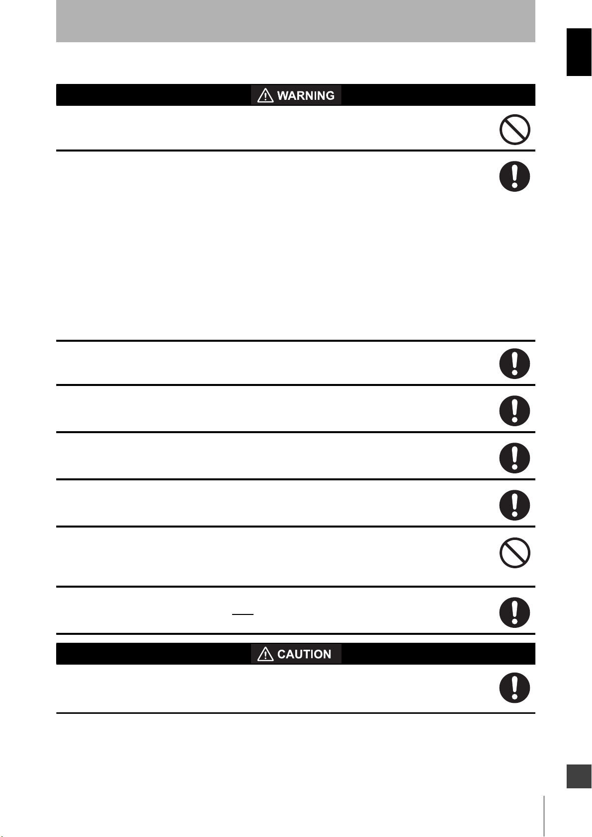
The Alert symbols and their meanings ensure safe use of the products
In order to use the OS32C safely, the precautions listed in this manual are indicated by alert symbols. The
descriptions must be followed, failure to follow all precautions and alerts may result in an unsafe installation or
operation.
The following indictions and symbols are used.
Meanings of Alert Symbols
Safety Precautions
Indicates a potentially hazardous situation which, if not avoided, will result in minor or moderate injury, or
may result in serious injury or death. Additionally there may be significant property damage.
Indicates a potentially hazardous situation which, if not avoided, will result in minor or moderate injury, or
there may be property damage.
Indicates prohibited actions.
Indicates mandatory actions.
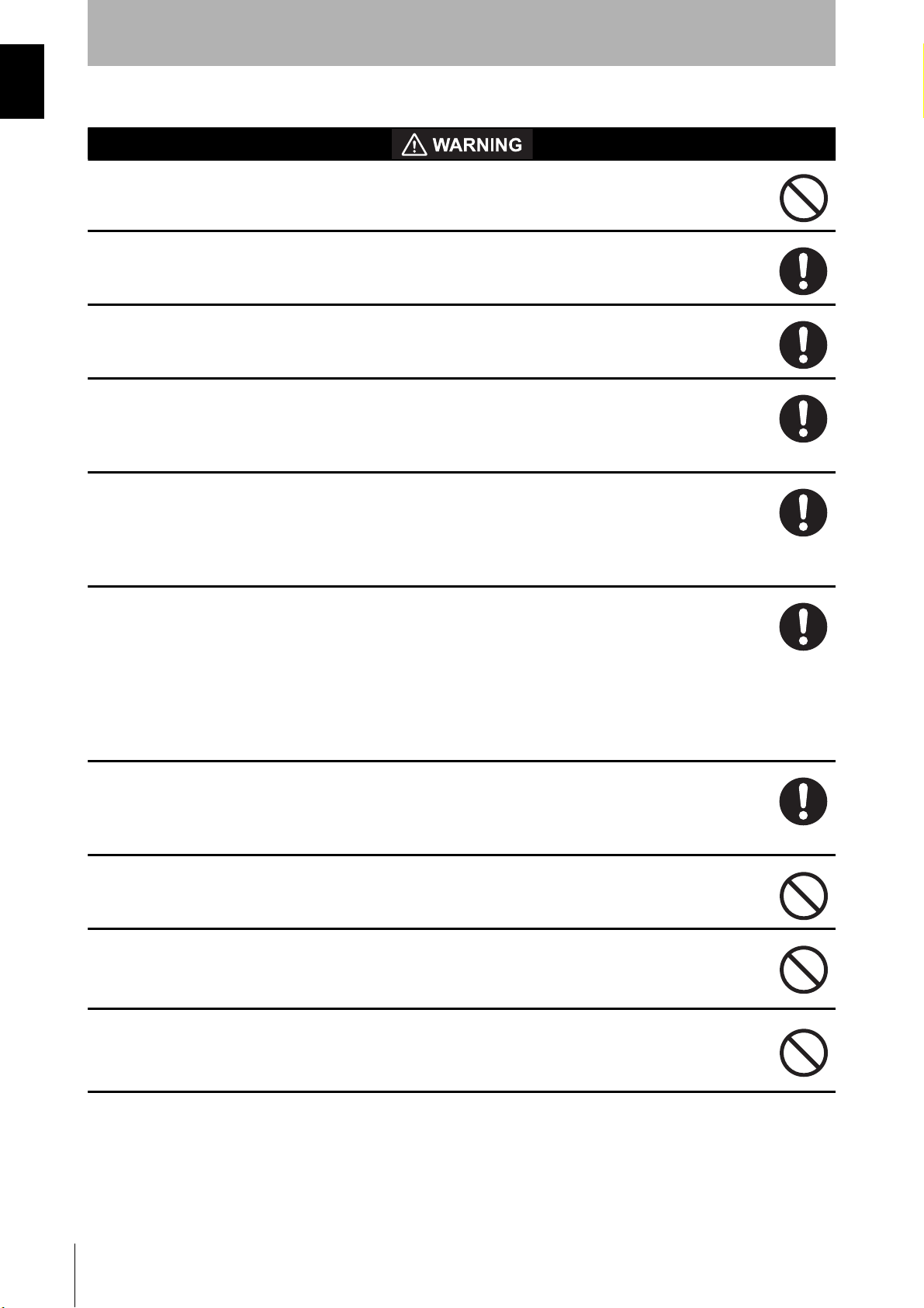
Alert Statements in this Manual
An OS32C is an electro-sensitive protective equipment designed to guard personnel working
around hazardous machinery.
Whether a specific machine application and the OS32C system installation complies with safety
regulations depends on the proper application, installation, maintenance and operation of the
OS32C system. These items are the responsibility of the purchaser, installer and user.
User
iv
The administrator is responsible for the selection and training of personnel to properly install,
operate, and maintain the machine and its safeguarding systems.
An OS32C system should only be installed, verified and maintained by a qualified person. A qualified
person is defined as ”an individual who understands, is trained on, and demonstrates competence with
the construction, operation or maintenance of the machinery and the hazards involved.” (ANSI/PMMI
B155.1-2006)
OS32C
User’s Manual
Page 7
The machine requirements
The guarded machine must be able to stop anywhere in its cycle. Do not use an OS32C on a press
with a full-revolution clutch.
The guarded machine must have a consistent stopping time and adequate control mechanisms.
All safety-related machine control elements must be designed so that an alarm in the control logic
or failure of the control circuit does not lead to a failure to danger.
Do not use the auxiliary output or warning output for safety applications. A human body may not be
detected even if a failure of OS32C occurs, resulting in serious injuries.
Installation
Introduction
The main unit must be securely mounted and its cable connectors must be tightly attached.
The OS32C must not be mounted behind glass or within a secondary enclosure. Failure to do so
will cause a reduction in detection capability, which can cause serious injury or death.
A start switch to release interlock must be installed where an operator can observe the monitored/
guarded zone as a whole and cannot operate the switch within the hazardous zone.
Per the International standard IEC 61496-3, area scanners used in applications where the angle of
approach exceeds +/- 30 degrees with respect to the detection plane, must use reference
boundary monitoring (RBM) of the detection zone.
Make sure to remove any retro-reflector from the field of view of the OS32C when in RBM mode.
A protective mechanism must be installed to prevent a hazardous condition in the event of a
subsequent machine component failure. The OS32C does not protect against ejected flying
material.
Severe smoke and particulate matter may degrade the efficiency of an OS32C, causing it to
unexpectedly enter a Machine Stop state.
Use of mirrors or mirror-like objects in the protection plane must be avoided, as they can hide part
of the area to be monitored/guarded.
Additional guarding may be required to prohibit access to dangerous areas not covered by the
OS32C system.
OS32C
User’s Manual
E
v
Page 8
Introduction
Perform the test procedure in this document at installation, after maintenance, adjustment, repair
or modification to the machine controls, tooling or the OS32C system. See page 162.
Perform only the test and repair procedures outlined in this manual.
Additional measurement error resulting from reflective backgrounds may need to be added to the
measurement error of the OS32C.
To use the protective function of the OS32C, a safety zone must be properly defined and
configured.
If the response time is changed, re-calculation of the safety distance is required. This may require
re-configuration of the safety zones or re-installation of the OS32C. If the safety distance is not
appropriate for the application, the machine may not stop before contact with the hazardous part,
resulting in serious injuries or death.
The activation of RBM Only mode will increase the response time. This additional time must be
taken into consideration when calculating the safety guarding distance.
When using more than one OS32C, mutual interference should be prevented. This may require
different scanner positions or physical shields to be installed.
To ensure a protection degree of IP65, DO NOT use this product without proper sealing of the
cable connector, I/O block, and scan window.
If the external zone switching device momentarily exceeds the configured number of active zone
set select inputs during the zone switch, an additional Zone Delay may be incurred in the event
that wiring of a zone set select input fails. The external zone switching device must properly
sequence so the configured number of active inputs is not exceeded in order to guarantee that
failed zone set select input wiring will be detected within the normal Zone Switching Time described below.
If an insufficient Zone Delay is used for the actual worst case switching time of the installation, the
scanner might start monitoring the wrong zone during the switching period.
Also, if an insufficient Zone Delay is used for the actual worst case switching time of the
installation, there might be a fault condition during the zone switching period.
If tstart (switching start time) is configured without consideration of TmaxReaction (total maximum
reaction time), object detection within the new safety zone after switching and turning OFF of the
safety outputs may be delayed.
vi
Monitoring zone parameters are subject to a number of constraints that include projective
consistency, maximum radius, and angle limits. As a result, an imported zone may not correspond
exactly to the zone defined in the file. The user must visually verify the imported zone when the
zone coordinate import process is complete. Refer to Checkout and Test Procedure Log on page
162.
The installer is responsible for assessing the risk and to ensure that the zone of limited detection
does not create a safety hazard. If a hazard exists additional countermeasure must be taken, this
may require additional guarding measures.
OS32C
User’s Manual
Page 9
Wiring Connections
Do not connect the OS32C to a power supply with more than 24VDC + 25% / -30%. Do not supply
AC power to the OS32C, this may result in electrical shock.
For the OS32C to meet IEC 61496-1 and UL 508, its DC power supply unit must satisfy all of the
following conditions:
• Within rated line voltage (24 VDC +25% / -30%)
• Complying with EMC directives (industrial environments)
• Double-insulation or reinforced insulation between primary and secondary circuits
• Automatic return for overcurrent protection
• Output retention time of 20 ms or longer
• Satisfying output characteristics requirements of Class 2 circuit or limited voltage/current circuit defined in
UL508.
• Power supply complying with regulations and standards of EMC and safety of electrical equipment in a
country or a region where OS32C is used. (Example: In EU, a power supply must comply with the EMC
and Low Voltage Directives.)
Introduction
To prevent electrical shock, use double-insulation or reinforced insulation from hazardous voltage
(such as 230 VAC).
Cable extensions must be within the specified lengths, otherwise it may result in a failure of the
safety functions.
To use this product for a category 3 safety system, both safety outputs must be connected to the
safety system. Configuring a safety system with only one safety output may result in serious
injuries due to output circuit fault and a failure of the machine to stop.
Protection of Cable at Installation:
Care should be taken when installing the OS32C cable. The cable must be properly routed and
secured to ensure that damage does not occur.
Functional Earth:
The OS32C system requires a functional earth connection.
Do not connect Functional Earth to a positive ground system. If it is connected to positive ground,
the guarded machine to be controlled may NOT stop, resulting in severe operator injury.
Signal Connector Isolation:
The connectors used during installation must provide sufficient signal separation in order to
prevent a short circuit condition of the input power and system signals.
When wiring the OS32C to external devices, make sure to follow the color and coding schemes
per EN 60204-1.
OS32C
User’s Manual
E
vii
Page 10
Introduction
Others
Do not modify the main unit of the OS32C. Do not replace or fix any component of the OS32C
other than the ones specified in this manual. Doing so may result in a failure of this device to
function correctly.
If there is any damage to the window, replace it as soon as possible. Otherwise it may result in a
failure of the OS32C. Take preventive measures when performing replacement work so that dust
does not enter the OS32C.
Always detach all cables from the OS32C before replacing the scan window. Otherwise the motor
may start rotating, resulting in injuries.
The window replacement procedure must only be performed by qualified personnel in a clean
environment at ambient temperature (5 to 35°C) to prevent the internal optical surface from
contamination. Make sure the inside and the outside of the replacement window is clean and free
from scratch, dust, and finger print.
The calibration procedure must only be performed by qualified personnel. Before performing
window calibration of the new scan window, make sure the window is clean and free from scratch,
dust, and finger print. The window calibration procedure must be performed at ambient
temperature 5 to 35°C. Failure to inspect the window or set the proper environmental condition
during window calibration procedure may cause a reduction in the detection capability of the scanner.
The tests outlined in the Test Procedure (See "Checkout and Test Procedure Log" in p.162) must
be performed at time of installation, according to the employer's regular inspection program and
after any maintenance, tooling change, set up, adjustment, or modification to the OS32C system or
the guarded machine. Where a guarded machine is used by multiple operators or shifts, it is
suggested that the test procedure be performed at each shift or operation change and also if there is a
change in the OS32C operating mode or defined zone sets. Testing ensures that the safety laser scanner and
the machine control system are working properly to stop the machine. Failure to test properly could result in
serious injury to personnel.
If the OS32C is operated under automatic start, make sure that the machine stops and does not
restart as long as an object is detected in a safety zone. Check the operation by placing a test
piece into the safety zone. It is recommended to perform the test at least after a shift change or 24
hours of operation.
If the safety system or the machine fails any of these tests, do not run the machine. Immediately
tag or lock out the machine to prevent its use and notify the appropriate supervisor.
System and zone status parameters monitored over EtherNet/IP are to be used for diagnostic
purposes only, and must not be used in safety-critical functions.
Measurement data monitored over EtherNet/IP are to be used for diagnostic purposes only, and
must not be used in safety-critical functions.
viii
OS32C
User’s Manual
Page 11
When transferring data from the PC to the OS32C and more than one OS32C is connected to the
network, it is necessary to visually check the diagnostic code on the status/diagnostic display. It is
recommended that the OS32C be installed in a position where the status/diagnostic display will be
visible.
Before sending the changes to the sensor, verify that the safety parameters are configured as
intended for the application.
Take precautions to prevent dirt, dust or debris from entering the sensor and I/O block connectors.
It is recommended that this be done on a clean workstation as contaminants may degrade the
performance of the OS32C.
Adhesion of dust to the scan window may cause a false operation. The OS32C will require periodic
cleaning of the scan window and dust detection surface.
Operation of the OS32C may be affected by light in the environment, such as incandescent light,
strobe light and light from a photosensor using infrared light.
Introduction
Operation of the OS32C may be affected by substances in the environment, such as fog, smoke,
steam and other small particles.
Ensure the measurement report configuration of the OS32C-xxx-DM matches the expected
measurement data format.
OS32C
User’s Manual
E
ix
Page 12

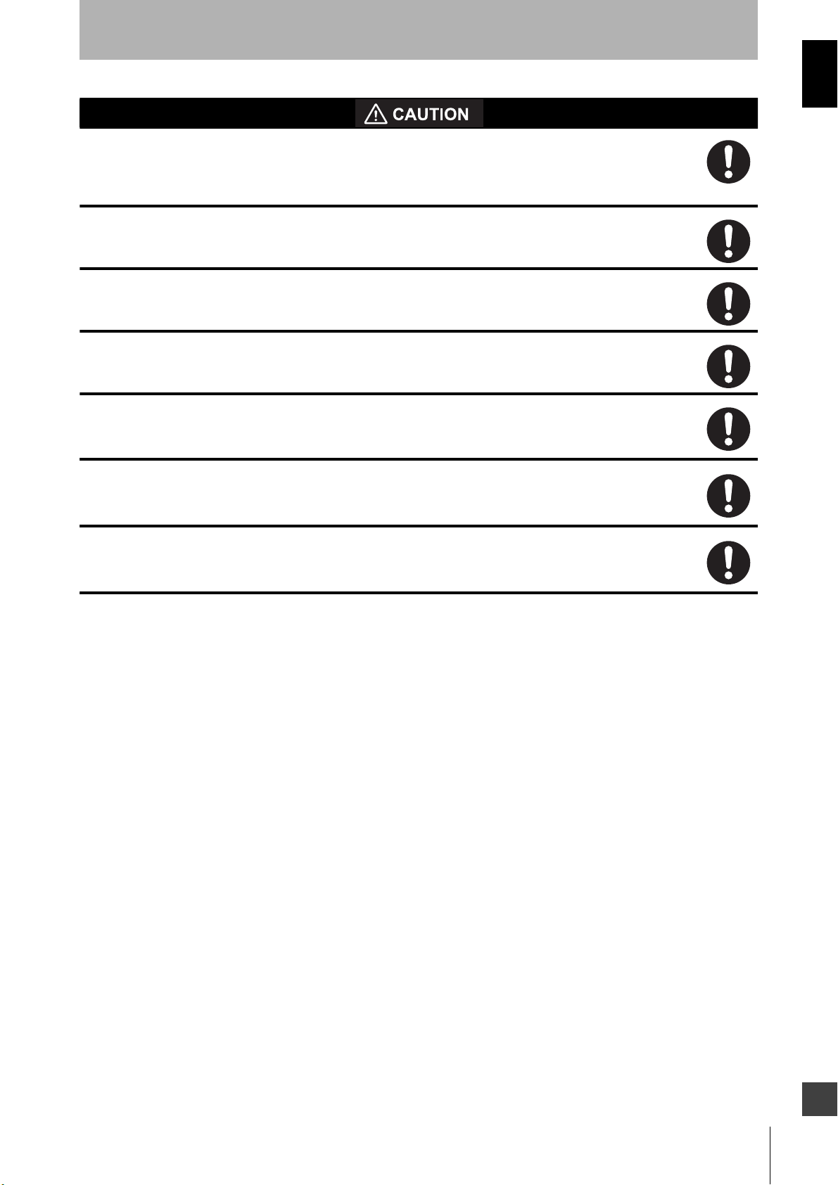
Introduction
Make sure to follow all the safety precautions that are necessary to ensure safe use of the product.
• Thoroughly read this installation manual and understand the installation, operation checks, and maintenance
procedures before using the product.
• Loads must satisfy both of the following conditions:
• The main unit must be properly mounted with the proper mounting hardware.
• Do not drop the product, serious damage will occur.
• Comply with all the laws, regulations, and standards of the country/region where the product is used.
• Dispose of the product in accordance with the relevant rules and regulations of the country/region where the
product is used.
Observe the precautions described below to prevent operation failure, malfunctions, or undesirable effects on
product performance.
Precautions for Safe Use
- Not short-circuited
- Not used with a current that is higher than the OSSD rating (250 mA sourcing)
Precautions for Correct Use
Installation environment
Do not install the OS32C in the following types of environments:
• Areas where OS32C may be exposed to intense interference light, such as direct sunlight
• Areas with high humidity where condensation is likely to occur
• Areas subject to condensation resulting from severe changes in temperature
• Areas where corrosive gases are present
• Areas exposed to vibration or shock levels higher than in the specification provisions
• Areas where the product may come into contact with water
• Areas where the product may get wet with oil
• Areas where smoke and/or water vapor exists on the laser scanning plane
• Keep the OS32C far enough from devices that generate high frequency noise or eliminate the
noise.
• Be sure to route the OS32C cable separate from high-potential power lines or route through an
exclusive conduit.
This is a class A product. In residential areas it may cause radio interference, in which case the
Responsible Person may be required to take adequate measures to reduce interference.
Wiring and installation
• Make sure to perform wiring while the power supply is OFF. Otherwise, the OS32C may fail to operate
due to the diagnostics function.
• Properly perform the wiring after confirming the signal names of all the terminals.
• Do not operate the control system until 14 seconds or more after turning ON the power of the OS32C.
• Be sure to route the OS32C cable separate from high-potential power lines or through an exclusive
conduit.
• When using a commercially available switching regulator power supply, make sure to ground the FG
terminal (frame ground terminal).
• Sharing the power supply with other devices may cause the OS32C to be affected by noise or voltage
drop. It is recommended that the safety-related devices use a dedicated power supply, not shared
with other devices.
OS32C
x
User’s Manual
Page 13

Cleaning
Do not use thinner, benzene, or acetone for cleaning. They will adversely affect the product's resin
parts and paint on the case.
Object detection
The OS32C has a configurable minimum object resolution of 30mm, 40mm, 50mm, or 70mm. It cannot
detect transparent or translucent objects, or objects with reflective surfaces, of less than 1.8%
reflectivity.
Introduction
OS32C
User’s Manual
E
xi
Page 14

Introduction
How to Read This Manual (Explanation of Symbols)
Indicates the description of an essential function, such as operation or advice on how to properly use
this product .
Indicates the page number for related content.
xii
OS32C
User’s Manual
Page 15

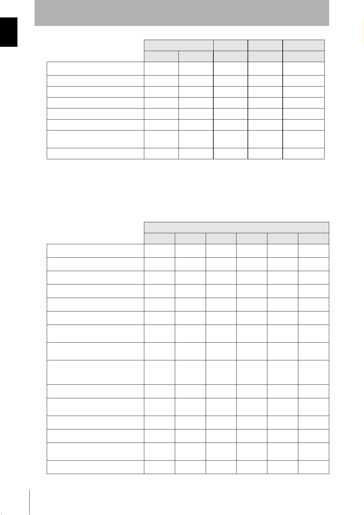
Configuration Tool Features and Compatibility
Please refer to the table below for supported features and compatibility with OS32C versions. Refer to the
product labels to determine the OS32C version.
For information on the OS32C-DM model, please refer to the OS32C-DM Addendum available on the
Omron's website at
http://www.omron.com/global/
NOTE:
• Only the version of the sensor block and the configuration tool were updated to support the new
features. No changes were made to the I/O block.
• The part numbers have changed:
OS32C-SN: 40591-0010 (old), 40591-0020 (current)
OS32C-SN-DM: 40591-0040 (current)
OS32C-SN-4M: 40603-0020 (current)
OS32C-SN-DM-4M: 40603-0040 (current)
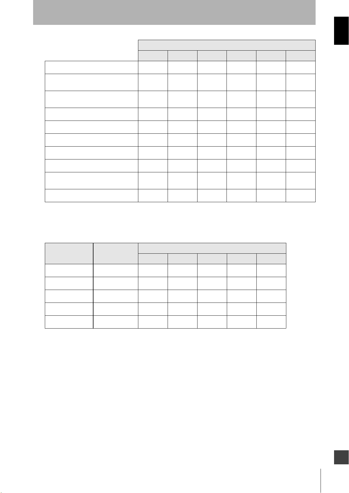
OS32C Versions OS32C-DM OS32C-4M OS32C-DM-4M
Introduction
: Supported 40591-0010 40591-0020 40591-0040 40603-0020 40603-0040
Configurable minimum object resolution
Standby mode with laser shutoff
Copy & paste zones and zone sets
Record system monitoring
Playback system monitoring
Support for inverting 7-segment display
Display configuration filename in config
tool header
Additional zone shapes (180° semi-circle,
180° rectangle, 180° polygon)
Config tool support for switching between
default OS32C configuration and the user's
current working configuration
Troubleshooting tips displayed in fault log
Configuration checksum, safety
checksum
--
--
--
--
--
--
--
--
--
--
*1 *1 *1 *1 *1
Windows 7 support
Non-safety checksum *2 *2 *2 *2 *2
Single Import & Export Zone Coordinate
Data
Maintenance access level --
Rotation of monitor screen view *4 *4 *4 *4 *4
French, German, Italian & Spanish
Languages
Multiple Import & Export Zone Coordinate
Data
--
*2 *2 *2 *2 *2
*3 *2 *2 *2
*4 *4 *4 *4 *4
*4 *4 *4 *4 *4
User’s Manual
E
OS32C
xiii
Page 16
Introduction
OS32C Versions OS32C-DM OS32C-4M OS32C-DM-4M
: Supported 40591-0010 40591-0020 40591-0040 40603-0020 40603-0040
EtherNet/IP and Measurement Data
Pollution Tolerance Mode -- *6 *6 *5 *5
Variable response time settings -- *6 *6 *5 *5
4 meter safety/ 15 meter warning zone -- -- -- *5 *5
Status information during monitor mode -- *6 *6 *5 *5
Confirmation of Safety parameters -- *6 *6 *5 *5
Warning Zone changed via Ethernet/IP
capability
Windows 10 support --
*1. Requires Configuration Tool Version 1.4.0 and up
*2. Requires Configuration Tool Version 1.6.0 and up
*3. If serial number of the sensor block is higher than AS08300 and Configuration Tool is version 1.6.0 and up
*4. Requires Configuration Tool is Version 1.8.0 and up
*5 Requires Configuration Tool is Version 2.0.0 and up
*6 If serial number of the sensor block is higher than AS17500 and Configuration Tool is Version 2.0.0 and up
*7. Requires Configuration Tool Version 2.2.8 and up
: Supported
-- --
-- --
*6 -- *5
--
*7 *7 *7 *7
Configuration Tool Version
before 1.4.0 1.4.0 and up 1.6.0 and up 1.8.0 and up 2.0.0 and up 2.2.8 and up
Configurable minimum object resolution
Standby mode with laser shutoff
Copy & paste zones and zone sets
Record system monitoring
Playback system monitoring
Support for inverting 7-segment display
Display configuration filename in config
tool header
Additional zone shapes (180° semi-circle,
180° rectangle, 180° polygon)
Config tool support for switching between
default OS32C configuration and the
user's current working configuration
Troubleshooting tips displayed in fault log
Configuration checksum, safety
checksum
Windows 7 support
--
--
--
--
--
--
--
--
--
--
--
--
xiv
Non-safety checksum
Single Import & Export Zone Coordinate
Data
Maintenance access level
OS32C
User’s Manual
-- --
-- --
-- --
Page 17
Configuration Tool Version
Introduction
: Supported
Rotation of monitor screen view
French, German, Italian & Spanish
Languages
Multiple Import & Export Zones
Coordinate Data
Pollution Tolerance Modes
Variable response time settings
4 meter safety/ 15 meter warning zone
Status information during monitor mode
Confirmation of Safety parameters
Warning Zone changed via Ethernet/IP
capability
Windows 10 support
Note: The configuration data file extension is *.cf2 until Configuration Tool Version 1.8.0 and *.cf3 from Version 2.0.0.
before 1.4.0 1.4.0 and up 1.6.0 and up 1.8.0 and up 2.0.0 and up 2.2.8 and up
-- -- --
-- -- --
-- -- --
-- -- -- --
-- -- -- --
-- -- -- --
-- -- -- --
-- -- -- --
-- -- -- --
-- -- -- -- --
: Supported
Model Sensor Head P/N
OS32C-SN 40591-0010
OS32C-SN 40591-0020
OS32C-SN-DM 40591-0040
OS32C-SN-4M 40603-0020
OS32C-SN-DM-4M 40603-0040
Configuration Tool Version
before 1.4.0 1.4.0 and up 1.6.0 and up 1.8.0 and up 2.0.0 and up
--
-- --
-- -- -- --
-- -- -- --
OS32C
User’s Manual
E
xv
Page 18

Introduction
xvi
OS32C
User’s Manual
Page 19

Contents
Legislation and Standards i
Terms and Conditions Agreement ii
Safety Precautions iv
Precautions for Safe Use x
Precautions for Correct Use x
Chapter1 Description of Use and Features 1
Theory of Operation 2
Features 3
System Components 4
Application Examples 5
Applying the OS32C to fixed stationary applications 5
Introduction
Applying the OS32C on Automated Guided Vehicles (AGV) 7
Rating/Performance 10
Chapter2 Operating States & Output Modes 13
Operating States 14
Operating Mode 17
Automatic Start 17
Start Interlock 17
Start/Restart Interlock 17
Power Reserve Mode 18
Parameter Configuration 19
Safety Critical Parameters 19
Non-Safety Critical Parameters 20
Safety Outputs 21
Auxiliary & Warning Outputs 21
Reference Boundary Monitoring (RBM) 23
Pollution Tolerance Mode (PTM) 24
Zone Set Selection 26
Zone Set Input Selection 26
Zone Set Switching 28
Chapter3 Basic Operation of Configuration Tool 33
Getting Started 35
Installing Configuration Tool 35
How to Start 36
Description of Screen 37
OS32C
User’s Manual
E
xvii
Page 20

Introduction
Menu 37
Tool Bars 39
Information Bar 40
Offline Mode 40
Connection to the OS32C 41
Connecting the PC and the OS32C 41
Forced DHCP mode 42
Changing the IP address of the PC (Windows XP) 42
Changing the IP address of the PC (Windows 7) 44
Changing the IP address of the PC (Windows 8.1 and Windows 10) 44
Logging on to the OS32C 45
Detecting the OS32C on the network 45
Logging On 46
Logging OFF 46
Changing Password 46
Forgot the Password? 47
Changing Ethernet Configuration of OS32C 48
Receiving OS32C Configuration Information 49
Configuring New OS32C Property and Monitoring Zone 49
Default Configuration Settings 49
Creating a New Configuration 50
Saving OS32C Configuration to PC 55
Import & Export Zone Coordinate Data 57
File Format 57
Importing Zone Coordinate Data 60
Exporting Zone Coordinate Data 62
Zone Set Selection and Configuration 64
Add a Zone 64
Copy and Paste Zones 65
Delete a Zone 67
Zone Set Input Selection 68
Editing Properties 69
xviii
Editing Monitor Zones 73
Sculpting & Reference Boundary Monitoring 76
Monitor Mode 81
Record System Monitoring 82
Playback System Monitoring 84
Read Fault Log 85
Window Calibration 86
Changing Options of Configuration Tool 88
Caution on Safety Zone Configuration 89
Reset to Default Configuration 90
OS32C
User’s Manual
Page 21

Chapter4 Installation 93
Mounting Considerations 94
Configuring Multiple OS32C Scanners 94
Distance from Wall 96
Stationary Installation and Configuration 97
Installation for Stationary Area Scanning 97
Configuration 98
Configuration Example: Installation on a Machine (1) 99
Configuration Example: Installation on a Machine (2) 101
Configuration Example: Entry Access Protection 101
Configuration Example: Hand Detection Protection 103
Mobile Installation and Configuration 105
Applying OS32C on Automated Guided Vehicles (AGV) 105
Configuration for Automated Guided Vehicles (AGV) 107
Configuration Example: Use of an AGV 108
Introduction
AGV Standards 109
External Dimensional Drawings 110
Ethernet Cable 119
XS5 OMRON SmartclickTM Connection 120
Chapter5 Wiring 121
Power Supply Unit 122
Additional Wiring Information 123
Input/Output Signal 124
Example of Safety Circuit 125
Chapter6 Checkout 129
Checkout and Test Procedures 130
Checkout and Test Procedures 130
Testing Safety Zone 131
Detection Capability 133
Chapter7 Appendix 135
Troubleshooting 136
Troubleshooting 136
OS32C Status Check 139
Additional Error due to Reflective Background 142
Conditions of Background Influence 142
Using Other Safety Device in Combination 144
Sensor Replacement 145
OS32C
User’s Manual
E
xix
Page 22

Introduction
Checking the Firmware Version 145
Sensor and I/O Block Replacement 147
How to Recover from a Fault Code 60 148
Scan Window Replacement Procedure 151
Window Replacement Procedure 151
OS32C Maintenance 153
Warning Zone Object Resolution 154
Additional Zone Set Switching Strategies 155
Glossary 159
Accessories 161
Checkout and Test Procedure Log 162
Declaration of Conformity 163
Revision History 165
xx
OS32C
User’s Manual
Page 23

Chapter1 Description of Use and Features
Theory of Operation 2
Features 3
System Components 4
Application Examples 5
Applying the OS32C to fixed stationary applications 5
Applying the OS32C on Automated Guided Vehicles (AGV) 7
Rating/Performance 10
Chapter1
OS32C
User’s Manual
E
1
Page 24

Description of Use and Features
Chapter1
Theory of Operation
The OS32C safety laser scanner is an optical safety sensor that uses diffuse reflection of a pulsed laser light
to determine the location of objects entering a predefined monitoring zone. Internally, a spinning mirror
assembly scans a monitoring zone by sending a pulse of light which reflects off the first object in its path. The
distance from the sensor to the object is determined by measuring the time that the light requires to return
from the sensed object.
This method of sensing allows for standard, simple or irregular shapes to be used as the predetermined
sensed monitoring zones. It also allows for the monitoring zone to be changed if the hazardous area changes.
Using diffused reflection of light back to the OS32C precludes the need for a traditional transmitter/receiver
pair.
Within the sensing range of the OS32C, three fields can be monitored simultaneously: One safety zone and
two warning zones.
• One Safety Zone is used to detect personnel or other objects entering an area that has been determined to
be a hazard. Upon sensing that the object is within the Safety Zone, the OS32C will send a stop signal to the
control circuitry of the machine being guarded.
• Two Warning Zones can be defined with a longer distance than a safety zone, allowing a configuration to
detect objects that are closely approaching the hazardous area of the Safety Zone before the actual Safety
Zone is encroached.
Applications for the OS32C include mobile applications on automatic guided vehicles (AGV) or transfer carts
as well as stationary use, such as within a robotic work cell, in front of a press or around other hazardous
machinery.
OS32C
2
User’s Manual
Page 25

Description of Use and Features
Features
• Can detect intrusions within the safety zone with a radius of up to 4 m (min. obj. resolution of 70mm) and two
warning zones with a radius of 15 m, covering a maximum scan angle of 270°.
• When an object is detected within the safety zone, individual sector indicators immediately turn on (8 red
indicators), indicating the object’s position of intrusion.
• Seventy sets of safety zone and warning zone combinations are available, supporting complicated changes
of working environments.
• The configuration tool allows easy to use monitoring zone configuration.
• A safety relay can be directly monitored by the external device monitoring function.
• The physical mounting position of the safety laser scanner can be monitored by the reference boundary
monitoring function.
• Compact design allows for low-clearance installations.
Chapter1
OS32C
User’s Manual
E
3
Page 26
Description of Use and Features
Chapter1
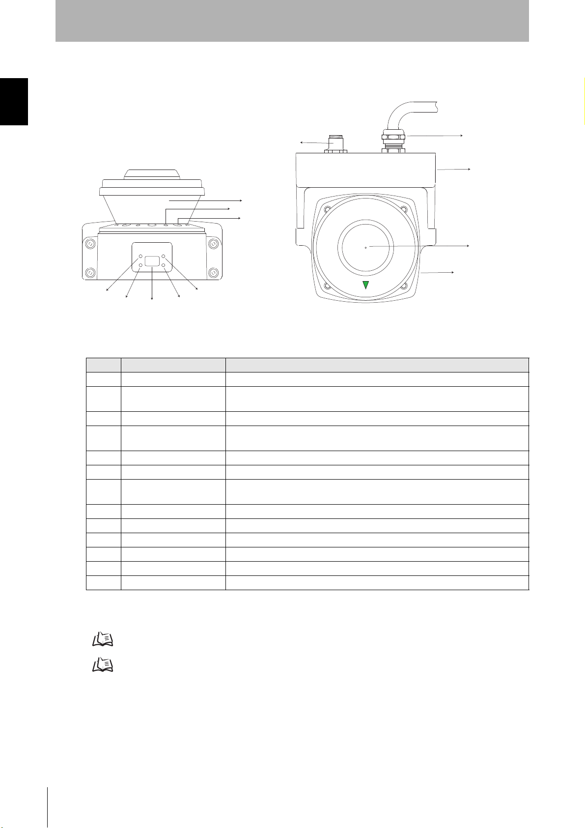
System Components
(1)
(2)
(3)
Fig. 1-1 System Components
(5)
(4)
(7)
(6)
(8)
(9)
(10)
(11)
(12)
(13)
Number Component Function
(1) RUN indicator (green) Will turn ON when safety zone is clear and OSSDs are ON.
Interlock Indicator (yellow) Will turn ON when in interlock state, blink under lockout (@ 1Hz), and blink under
(2)
(3) Status/Diagnostic Display The scanner's status ,configuration/operation, or failure is displayed.
Warning Output Indicator
(4)
(orange)
(5) STOP indicator (red) Will turn ON when safety zone is blocked, OSSD are OFF or under interlock state.
(6) Dust Ring Dust detection cover with reflective surface, for dust accumulation detection
Individual Sector Indicators
(7)
(ISI)
(8) Scan Window The window where the laser light is emitted and received.
(9) Communication Connector Provides for Ethernet interface.*1
(10) Power Connector For power connections, 18-pin connector (pigtail).*1
(11) I/O Block Connector module
(12) Center of rotation Indicates the location of the axis around which the laser irradiates from.
(13) Sensor Sensor head; field replaceable.
*1: The communication and power connections can also be mounted on the left side of the I/O block.
Table 1-1 System Components and Indicators
configuration (@ 4Hz).
Will turn ON when the warning output is ON and will flash when dust or contamination
is detected on the scan window (@ 1 Hz).
Will turn ON when an intrusion is detected in the safety zone (default), 8 sectors total. Each
sector = 33.75°. Will flash when dust or contamination is detected on the scan window.
For details on indicators, refer to "Indication Patterns" on page 14.
For details on Status/Diagnostic Display, refer to "OS32C Status Check" on page 139.
OS32C
4
User’s Manual
Page 27
Description of Use and Features
Application Examples
The OS32C may be used for personnel safeguarding. Typical applications include work cell area guarding
and collision prevention of AGV (Automated Guided Vehicles). The OS32C is a versatile Safety Laser
Scanner capable of guarding many types of applications. The application examples in this chapter are for
informational and instructional purposes only and not intended to represent complete guarding solutions.
Care must be taken to ensure that all aspects of a machine or work cell are reviewed and appropriate
guarding techniques are employed.
Applying the OS32C to fixed stationary applications
Chapter1
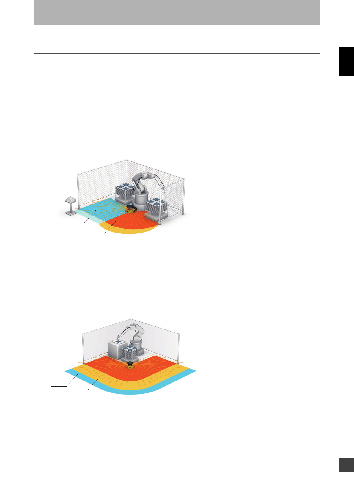
Zone A
Zone B
Fig. 1-2 Dual Zone Area Guarding
In this application the OS32C is the primary guarding device, using a horizontal protective field for area
protection. The OS32C will guard one side of the area based on the robot’s position. This application
takes advantage of the multi-zone functions of the OS32C. This function allows an operator to enter
and set-up on one side “the safe side” shown as Zone A, while the robot performs its tasks on the
“hazardous side” shown as Zone B. The warning zones are represented by the lighter colors. The
robot’s position is determined via external devices that provide discrete inputs to the OS32C.
Zone A
Zone B
Fig. 1-3 270 deg. Area Guarding
In this application the OS32C is the primary guarding device, using a 270 degree horizontal protective
field for area protection guarding. The production process in this example does not allow for any frontal
hard guarding obstructions in front of the work cell. The warning fields (shown as Zone A & Zone B) of
the OS32C provides manufacturing personnel with a preliminary warning to prevent them from
accidentally stopping the manufacturing process. In some cases an unintentional interruption can
result in very high waste costs.
OS32C
User’s Manual
E
5
Page 28
Chapter1
Description of Use and Features
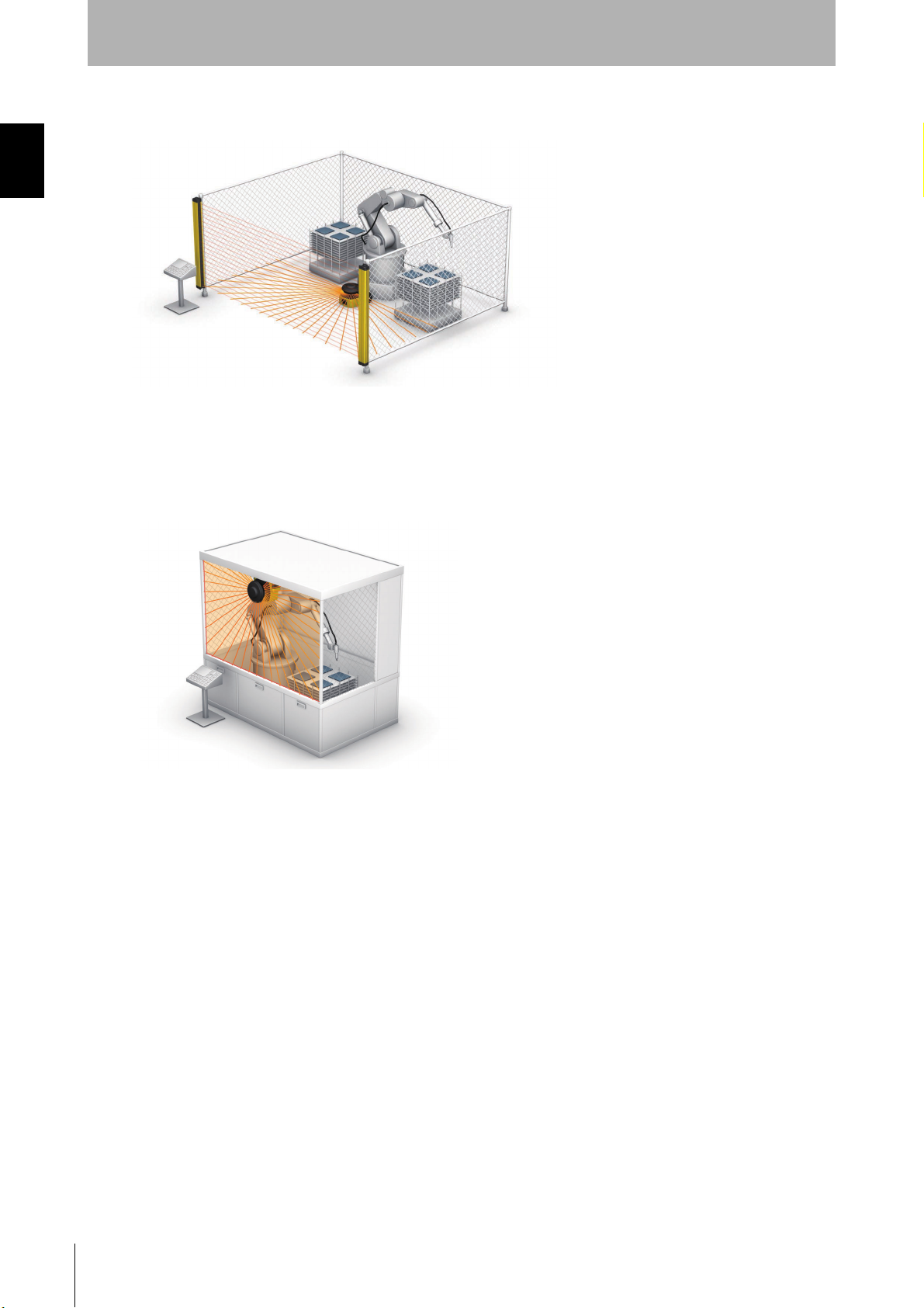
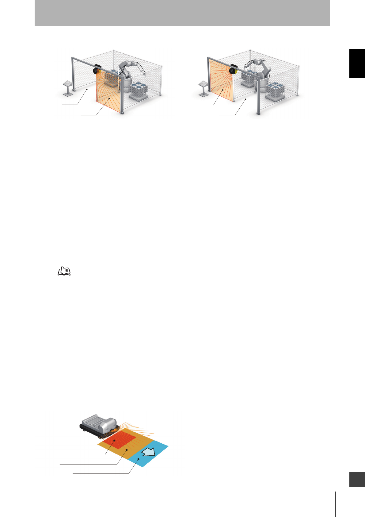
Fig. 1-4 Internal Robot Cell Guarding
In this application the OS32C is the secondary guarding device in conjunction with a safety light
curtain. The OS32C is responsible for detecting that the work area is clear before start-up of the robot
occurs.
Fig. 1-5 Vertical Guarding Installation
In this application the OS32C is the primary guarding device, using a vertical protective field for point of
operation guarding. In some cases the machine’s architecture or production flow may not permit the
installation of a safety light curtain. The OS32C meets all the requirements of IEC 61496-3 for vertical
guarding installations and employs a reference boundary monitoring function.
OS32C
6
User’s Manual
Page 29
Description of Use and Features
Chapter1
Zone-1
Zone-2
Fig. 1-6 Dual Zone Vertical Guarding
Zone-1
Zone-2
In this application the OS32C is the primary guarding device, using a vertical protective field for entry
presence detection. The OS32C can guard the hazardous area based on the robot’s position. When
the robot is in the left side, the OS32C guards the left side and changes to the right side along with the
robot. This application takes advantage of the multi-zone functions of the OS32C. This function allows
an operator to enter and set-up on one side, “the safe side”, while the robot performs its tasks on the
hazardous side. The robot’s position is determined via external devices that provide discrete inputs to
the OS32C. The OS32C meets all the requirements of IEC 61496-3 for vertical guarding installations
and employs a reference boundary monitoring function.
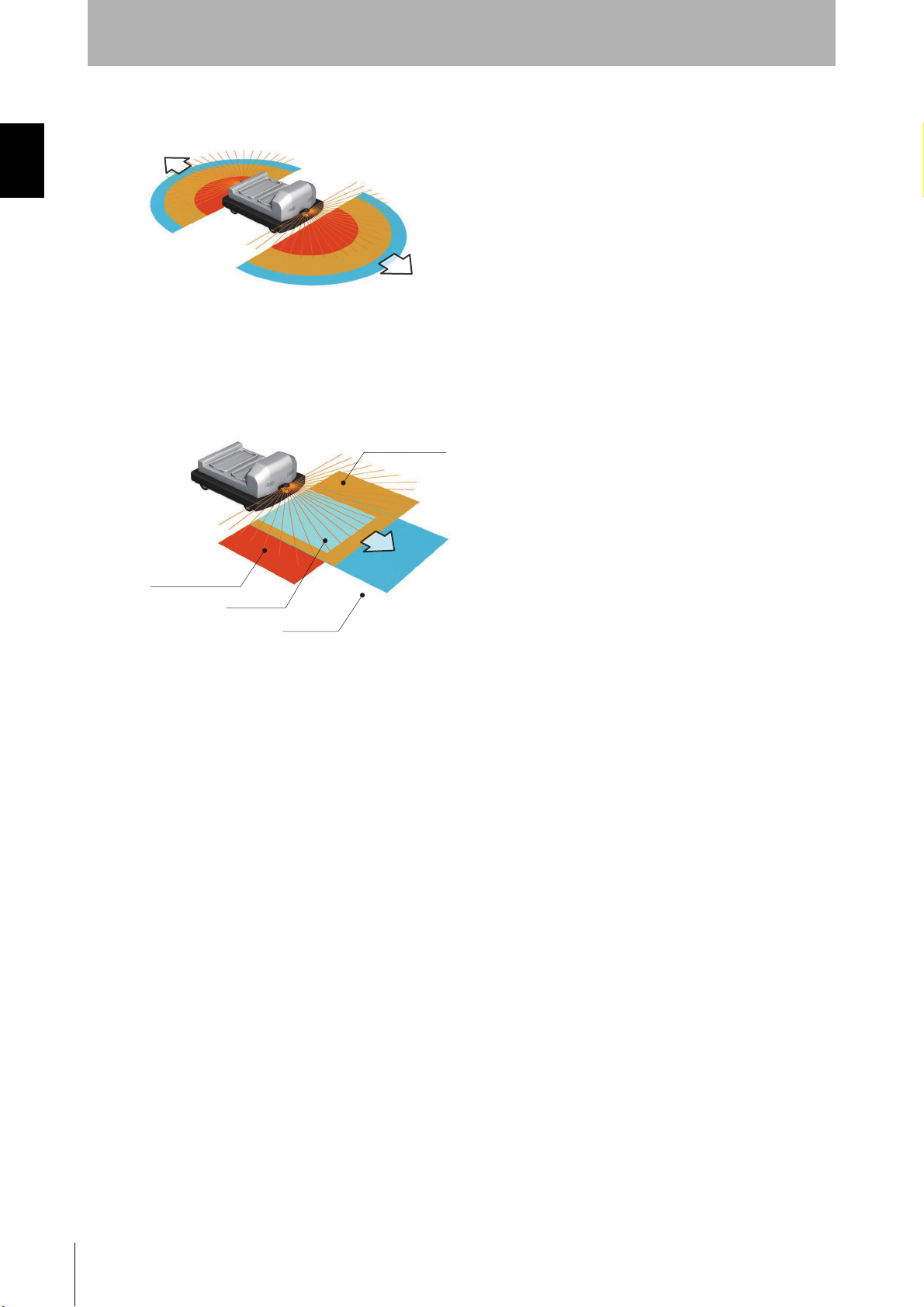
Applying the OS32C on Automated Guided Vehicles (AGV)
Unmanned automated vehicles require guarding devices to prevent accidental collisions. The OS32C
will scan the path of the AGV and will send a stop signal to the vehicle if it detects an object or person.
The OS32C is more adjustable and reliable than conventional pressure-sensitive bumpers.The
OS32C's flexibility allows three types of monitoring.
See Fig. 1-7
Warning Zone 1 Detection
When the Warning Output is assigned to follow Warning Zone 1, it will send a signal to the AGV when
Warning Zone 1 is infringed. This will trigger the vehicle to sound an alarm, allowing a person to move
away from the vehicle’s path.
Warning Zone 2 Detection
When the Auxiliary Output is assigned to follow warning zone 2, it will send a signal to the AGV when
Warning Zone 2 is infringed. This will trigger the vehicle to slow down, allowing a person to move away
from the vehicle’s path.
Safety Zone Detection
The two safety outputs will send an E-stop to the AGV when the Safety Zone is infringed. This will
signal the vehicle to come to a complete stop.
Safety Zone Detection
Warning Zone 2 Detection
Warning Zone 1 Detection
Fig. 1-7 AGV Navigation
E
OS32C
User’s Manual
7
Page 30
Chapter1
Description of Use and Features
Fig. 1-8 Automated Guided Vehicles, Bi-directional (AGV)
In this application two OS32Cs are the primary guarding devices. The two warning fields of the OS32C
are used to give personnel extra warning, allowing them to move out of the AGV path. This is essential
in achieving maximum travel efficiency.
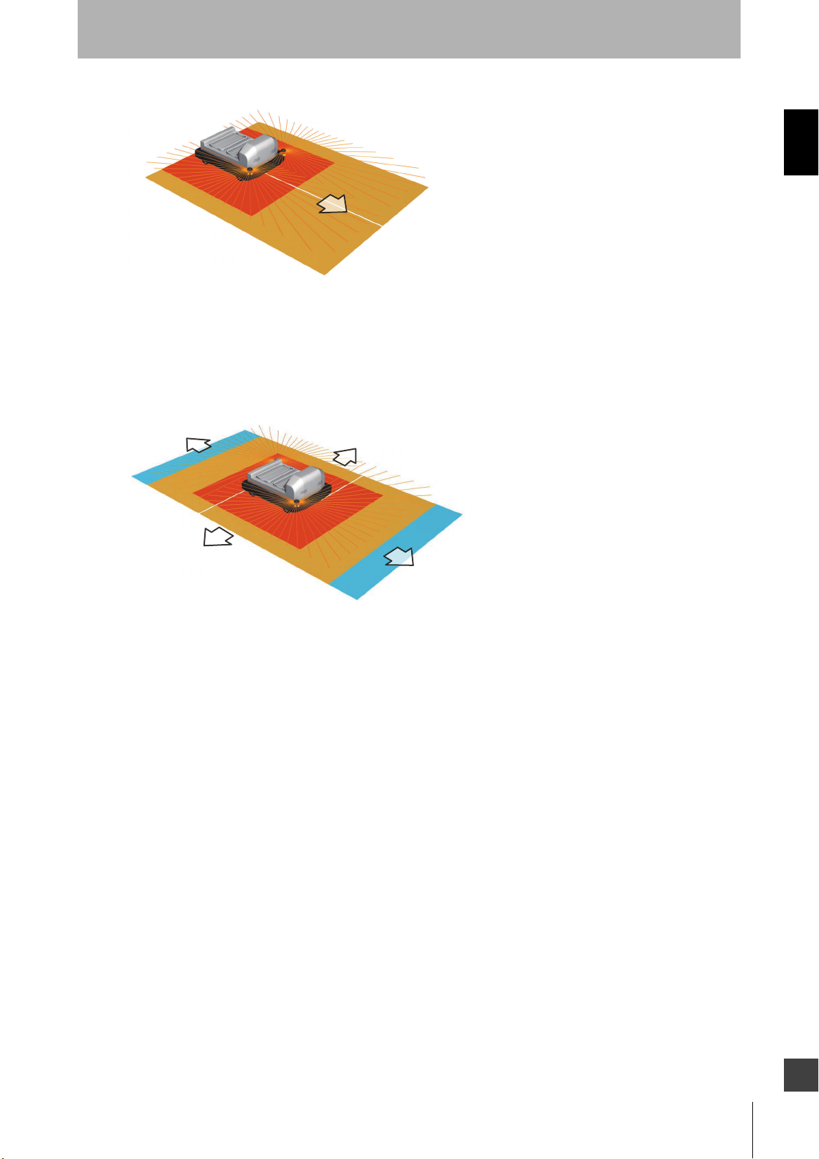
Left Turn Zone
Right Turn Zone
Slow Zone
Fast Zone
Fig. 1-9 Automated Guided Vehicles, Multiple Zones (AGV)
In this application the OS32C is the primary guarding device. The drawing illustrates a common AGV
guarding configuration where 4 zone sets are used to safely navigate the vehicle around a factory floor.
The four zone sets consist of two for forward motion (high speed, low speed), one for left turn and one
for right turn. The active safety zone set is selected by the AGV’s controls, which are configured for
maximum efficiency.
OS32C
8
User’s Manual
Page 31
Description of Use and Features
Fig. 1-10 Automated Guided Vehicles (AGV), Two Scanners, Three Sided
In this application two OS32Cs are used as the primary guarding devices, using 270 degree protective
fields. They are positioned at the front corners, this scheme allows for two scanners to guard three
sides of the AGV. This configuration is appropriate for AGVs that can maneuver in three directions,
forward and side-to-side.
Chapter1
Fig. 1-11 Automated Guided Vehicles (AGV), Two Scanners, Four Sided
In this application two OS32Cs are used as the primary guarding devices, using 270 degree protective
fields. They are positioned at opposite corners. This scheme allows for two scanners to guard four
sides of the AGV. This configuration is appropriate for AGVs that can maneuver in four directions,
forward, reverse and side-to-side.
OS32C
User’s Manual
E
9
Page 32

Description of Use and Features
Chapter1
Rating/Performance
Sensor Type Type 3 Safety Laser Scanner
Performance Level (PL)/
Safety Category
Functional Safety of
Electrical/Electronic/
Programmable Electronic
Safety-related Systems
Detection Capability
Monitoring Zone Monitoring Zone Set Count (Safety Zone + 2 Warning Zones) : 70 sets max.
Operating Range
OS32C-xxx
Operating Range
OS32C-xxx-4M
Maximum Measurement Error
Detection Angle 270°
Angular Resolution 0.4 degree
Laser Beam Diameter 6 mm at optics cover, 14 mm (typical) at 3 m.
Laser Scan Plane Height
Response Time
Zone Switching Time From 20 to 320 ms
Line voltage 24 VDC +25%/-30% (ripple p-p 2.5 V max.) *2
Power Consumption
Emission Source
(Wavelength)
Laser Protection Class
Safety Output (OSSD)
Auxiliary Output (Non-Safety)
Warning Output (Non-Safety)
Operation Mode Auto Start, Start Interlock, Start/Restart Interlock
External Device
Monitoring
Input
Connection Type
Start ON: 0 V short (input current of 20 mA), OFF: Open
Zone Select ON: 24 V short (input current of 5 mA), OFF: Open
Standby ON: 24 V short (input current of 5 mA max.), OFF: Open
PL d, Safety Category 3 (ISO13849-1)
SIL 2, PFH
Configurable via the configuration tool; Non-transparent with a diameter of 30, 40, 50, or 70 mm (1.8%
reflectivity or greater)
Safety Zone: 1.75 m (min. obj. resolution of 30 mm)
Warning Zone: 10.0 m
Safety Zone: 1.75 m (min. object resolution of 30mm)
Warning Zone: 15.0 m
100 mm (at range of 3 m or less) *1
110 mm (at range greater than 3 m and up to 4 m) *1
67 mm from the bottom of the scanner (see "External Dimensional Drawings" on page 110 for more
detail)
Response time from ON --> OFF: From 80 ms (2 scans) to 680 ms (up to 17 scans) *8
Response time from OFF --> ON: Configurable. See Table 2-5 on page 16.
Normal operation: 5 W max. *3
Standby mode: 3.75 W (without output load)
Infrared Laser Diode (905 nm)
Class 1: IEC/EN60825-1
Class 1: JIS C 6802
Class I: CFR21 1040.10, 1040.11
PNP transistor x 2, load current of 250 mA max., residual voltage of 2 V max., load capacitance of 2.2 μF
max., leak current of 1 mA max *3, *4, *5.
NPN/PNP transistor x 1, load current of 100 mA max., residual voltage of 2 V max., leak current of 1 mA
max *4, *5, *7
NPN/PNP transistor x 1, load current of 100 mA max.,residual voltage of 2 V max., leak current of 1 mA
max *4, *5, *7
ON: 0 V short (input current of 50 mA), OFF: Open
Power Cable: 18-pin mini-connector (pigtail)
Communication Cable: M12, 4-pin connector
D = 8.3 x 10
2.5 m (min. obj. resolution of 40 mm)
3.0 m (min. obj. resolution of 50 mm or 70 mm)
2.5 m (min. object resolution of 40 mm)
3.0 m (min. object resolution of 50 mm)
4.0 m (min. object resolution of 70 mm)
-8
(IEC61508)
10
OS32C
User’s Manual
Page 33

Description of Use and Features
Connection with PC
Indicators
Protective Circuit Protection against output load short and reverse power connection
Ambient Temperature Operation: -10 to 50 °C, Storage: -25 to 70 °C
Ambient Humidity Operation & Storage: 95%RH max., non-condensing
Ambient Operation
Illumination
Insulation resistance 20 MΩ or higher (500 VDC)
Dielectric withstand voltage 350 VAC, 1 minute
Enclosure Rating IP65(IEC60529)
Enclosure
Dimensions (WxHxD) 133.0 x 104.5 x 142.7 mm (except cable)
Impact Resistance 98 m/s
Vibration 10 to 55 Hz double-amplitude of 0.7 mm, 20 sweepings for X, Y, and Z directions (IEC60068-2-6)
Weight (Main Unit only) 1.3 kg
Power Cable Up to 30 m
Communication Cable Up to 100 m for 100 BASE-TX cable *9
Approvals
*1. An additional measurement error may need to be added due to reflective backgrounds (See p.142 for details).
*2. For power source specification, see Power Supply Unit in p.122
*3. Rated current of OS32C is 1.025 A max. (OS32C 210 mA + OSSD A load + OSSD B load + Auxiliary output load + Warning output
load + Functional Inputs).
Where functional inputs are:
EDM input ... 50 mA
Start input ... 20 mA
Standby input ... 5 mA
Zone X input ... 5 mA x 8 (eight zone set select inputs)
*4. Output voltage is Input voltage - 2.0 VDC.
*5. Total consumption current of 2 OSSDs, auxiliary output, and warning output must not exceed 700 mA.
*6. An Ethernet cable with an M12, 4-pin connector is required.
*7. Output polarity (NPN/PNP) is configurable via the configuration tool.
*8. Pollution tolerance in RBM mode will increase the scan period, resulting in an increase of the response time. See Table 2-5 for
detail.
*9. Omron only supplies up to a 15 m Ethernet cable. For longer lengths a connection to a network switch/router is needed.
Table1-2 OS32C Specifications
Communication: Ethernet *6
OS Supported: Windows XP, Windows 7, Windows 8.1, Windows 10
RUN indicator : Green, STOP indicator : Red, Interlock Indicator : Yellow, Warning Output Indicator :
Orange
Status/Diagnostic Display: 2 x 7-segment LEDs, Individual Sector Indicators: Red LED x 8
Incandescent lamp: Illumination on receiving surface 1500 lx max. (an angle of laser scanning plane and
disturbance light must be +/-5 degrees or more)
Sensor Head: Die-cast aluminum
Optics Cover: Polycarbonate
I/O Block: Die-cast aluminum
2
1000 times for each of X, Y, and Z directions (IEC60068-2-29)
Certificated by: TÜV Rheinland, UL
EN61496-1 (Type 3 ESPE), EN61496-3 (Type 3 AOPDDR), EN61508 (SIL2),
IEC61496-1 (Type 3 ESPE), IEC61496-3 (Type 3 AOPDDR), IEC61508 (SIL2),
UL508, UL1998, CAN/CSA-C22.2 No. 14, CAN/CSA-C22.2 No. 0.8
Chapter1
OS32C
User’s Manual
E
11
Page 34

Chapter1
Description of Use and Features
12
OS32C
User’s Manual
Page 35

Chapter2
Operating States 14
Operating Mode 17
Parameter Configuration 19
Safety Outputs 21
Auxiliary & Warning Outputs 21
Operating States & Output Modes
Automatic Start 17
Start Interlock 17
Start/Restart Interlock 17
Power Reserve Mode 18
Safety Critical Parameters 19
Non-Safety Critical Parameters 20
Chapter2
Reference Boundary Monitoring (RBM) 23
Pollution Tolerance Mode (PTM) 24
Zone Set Selection 26
Zone Set Input Selection 26
Zone Set Switching 28
OS32C
User’s Manual
E
13
Page 36

Operating States & Output Modes
Operating States
The following operating states exist for the OS32C system.
Chapter2
1. OSSD ON State
The two safety outputs are in the ON state, and the machine run (green) indicator is lit. The protected
machine is allowed to operate. The state/diagnostic display indicates a state of monitoring zone set selection
and a response time.
2. OSSD OFF State
An object exists in a safety zone and it is being detected. The two safety outputs are in the OFF state, and the
machine stop (red) indicator and the intrusion indicators in the affected region(s) are lit. The protected
machine is not allowed to operate. The status/diagnostic display shows "- -".
3. Interlock State
This state waits for a start input (See p.17 for details.). The two safety outputs are in the OFF state, the red
STOP indicator and yellow interlock indicator are lit. The protected machine is not allowed to operate. The
status/diagnostic display shows "01".
4. Lockout State
A failure is being detected and the guarded machine is being stopped. The two safety outputs are in the OFF
state, the machine stop (red) indicator is lit and yellow interlock indicator is flashing. The protected machine is
not allowed to operate. The status/diagnostic display shows the diagnostic code that caused the lockout. The
OS32C system will remain in the lockout state until the problem is corrected and a start input is applied (see
page 17 Start Interlock for details) or power on the unit is cycled.
Indication Patterns
RUN indicator
(Green LED)
STOP indicator
(Red LED)
Interlock Indicator
(Yellow LED)
Warning output indicator
(Orange LED)
Status/Diagnostic Display
Individual Sector Indicators (ISI)
(Red LED)
*1 The functionality of the intrusion indicators is configurable via the configuration tool.
*2 The intrusion indicators in the affected region is lit or flashing.
Table 2-1 Indication Patterns
On When OSSD is ON
Off When OSSD is OFF
On When OSSD is OFF
Off When OSSD is ON
On Interlock State
Flashing Lockout State (@ 1Hz), Configuration State (@ 4Hz)
Off Other than the above
On When any warning zone is intruded
Flashing When dust or contamination is detected on the scan window (@ 1 Hz)
Off Other than the above
On When an object is in any safety or warning zone. *1, *2
Flashing When dust or contamination is detected on the scan window. *1
Off Zones are clear and window is clean.
See "OS32C Status Check" on page 139.
14
OS32C
User’s Manual
Page 37

Operating States & Output Modes
State
Power On Self Test On On On On Off
Machine Stop Off On Off Depends on
Machine Run (Normal Operation) On Off Off Depends on
Machine Run (Dust on scan window) On Off Off Flashing (@ 1 Hz) On
Interlock Off On On Depnds on
Standby Off On Off Off Off
Fault (Dust on scan window) Off On Flashing (@ 1Hz) Flashing (@ 1 Hz) Off
Fault (others) Off On Flashing (@ 1Hz) Off Off
Configuration Off On Flashing (@ 4Hz) Off Off
Table 2-2 OS32C Operating States and Corresponding Outputs
RUN indicator
(Green LED)
STOP indicator
(Red LED)
Interlock indicator
(Yellow LED)
Warning output
indicator
(Orange LED)
configuration and
object position
configuration and
object position
configuration and
object position
Status/Diagnostic Display
When powered up, the OS32C will display, in the following order:
• the configured minimum object resolution for 5 seconds, as indicated in the following table:
Digital Indication Minimum object resolution
L3 30mm
L4 40mm
L5 50mm
L7 70mm
OSSDs
Off
On
Off
Chapter2
Table 2-3 Minimum object resolution indication
• the Ethernet configuration of the OS32C for 5 seconds, as indicated in the following table:
Digital Indication OS32C Ethernet configuration
SP Static IP addressing
dP DHCP IP addressing
Table 2-4 Ethernet configuration indication
This will also be displayed for 5 seconds after every time the Ethernet cable is connected to the
scanner.
• Normal operation indication: zone number and response time. See next page for details.
E
OS32C
User’s Manual
15
Page 38

Chapter2
Operating States & Output Modes
During normal operation:
The seven-segment display indicates the current zone set and response time of the OSSDs. For
example, code 24 indicates zone set 2 with a response time of 160ms.
When the display is inverted, a decimal will be shown in the corner.
The response times longer than 400ms are represented by zero.
Left Digit
Monitoring Zone of OS32C Digital Indication
Zone Set 1 1
Zone Set 2 2
Zone Set 3 3
Zone Set 4 4
Zone Set 5 5
Zone Set 6 6
Zone Set 7 7
Zone Set 8 8
Zone Set 9 9
Zone Set 10 A
Zone Set 11 b
Zone Set 12 C
Zone Set 13 d
Zone Set 14 E
Zone Set 15 F
Zone Set 16 or higher U
Right Digit
ON to OFF Response time
OSSDs out put Auxiliary and Warning Output
(without
PTM-RBM)
80 ms 94 ms 120 ms 140 ms
120 ms 140 ms 160 ms 186 ms 3 3
160 ms 186 ms 200 ms 232 ms 4 4
200 ms 232 ms 240 ms 278 ms 5 5
240 ms 278 ms 280 ms 324 ms 6 6
280 ms 324 ms 320 ms 370 ms 7 7
320 ms 370 ms 360 ms 416 ms 8 8
360 ms 416 ms 400 ms 462 ms 9 9
400 ms 462 ms 440 ms 508 ms 10 0
440 ms 508 ms 480 ms 554 ms 11 0
480 ms 554 ms 520 ms 600 ms 12 0
520 ms 600 ms 560 ms 646 ms 13 0
560 ms 646 ms 600 ms 692 ms 14 0
600 ms 692 ms 640 ms 738 ms 15 0
640 ms 738 ms 680 ms 784 ms 16 0
680 ms 784 ms 720 ms 830 ms 17 0
*1. Restart Delay parameter is configurable from 100ms to 60s with 100ms increment
See p.52 for configuring the Restart Delay parameter.
*2. See Pollution Tolerance Mode section, p.24, for more information
Table 2-5 Status/Diagnostic Display Indication
(with PTM-RBM
active)*2
(without
PTM-RBM)
(with PTM-RBM
active)*2
OFF to ON Response time
(Configurable)
The OFF to ON response
time = corresponding ON
to OFF response time +
Restart Delay parameter*1
Number of
Scans
22
Digital
Indication
16
OS32C
User’s Manual
Page 39

Operating Mode
Start Interlock
Power
Object in
safety zone
Start input
OSSDs
ON
OFF
ON
OFF
State of OS32C Interlock Machine run
No
Present
0 V short
Open
180 ms max.
200 ms min.
Start/Restart Interlock
At power on
Power
Object in
safety zone
Start input
OSSDs
ON
OFF
ON
OFF
State of OS32C Interlock Machine run
No
Present
0 V short
Open
180 ms max.
200 ms min.
At restart
Power
Object in
safety zone
Start input
OSSDs
ON
OFF
ON
OFF
State of OS32C Interlock
Machine
run
Machine
run
No
Present
0 V short
Open
180 ms max.
200 ms min.
Automatic Start
After power on, OS32C automatically enters machine run (ON) state if no fault is detected during
initialization and self-tests, and if no intrusion is detected within the safety zone. An object entering the
safety zone shall turn the OSSDs OFF. Once the safety zone is clear, the sensor will automatically
enter the machine run (ON) state.
Start Interlock
After power on, OS32C automatically enters the interlock state if no fault is detected in its system
initialization and self-tests, and if no intrusion is detected within the safety zone. To release the
interlock state, the start input must transition to open from 0 V for a minimum of 200ms and then back
to 0 V short. Once the interlock state is released and OS32C enters the machine run (ON) state, an
object entering the safety zone will turn the OSSDs OFF. Once the safety zone is clear, the sensor will
automatically enter the safety output ON state.
Operating States & Output Modes
Chapter2
Start/Restart Interlock
After power on, OS32C automatically enters the interlock state if no fault is detected in its system
initialization and self-tests, and if no intrusion is detected within the safety zone. To release the
interlock state, the start input must transition to open from 0 V for a minimum of 200ms and then back
to 0 V short. Once the OS32C has started and enters the machine run (ON) state, an object entering
the safety zone will turn the OSSDs OFF. Once the safety zone is clear, the sensor will enter the
interlock state.
OS32C
User’s Manual
E
17
Page 40

Chapter2
Power Reserve Mode (Standby Mode)
Power
Object in
safety zone
Standby input
OSSDs
ON
OFF
ON
OFF
Status/
diagnostic display
State of OS32C
Machine
run
Machine
run
No
Present
+24 VDC
Open
Less than 0.5 s
Standby mode
"--" (blinking)*1 *1
Operating States & Output Modes
Power Reserve Mode
Power reserve mode allows the OS32C to enter a state of reduced power consumption. This is a very
useful mode when the OS32C is installed on a battery powered AGV. This mode can be configured for
Standby Mode:
•OSSDs, AUX and WARNING outputs will be off.
•Laser is off.
•Individual Sector indicators will be deactivated.
•Diagnostic display will display “- -”, which blinks once every 2 seconds.
•Wake-up time (time it takes for the OS32C to return to normal mode) is less than 0.5s.
To use Standby mode:
•Enable Standby mode under the Power Reserve property and send this change to the scanner.
•Wire the standby input to a normally open contact, see Chapter 5 for wiring diagram.
To activate standby mode:
•The closure of a normally open contact needs to connect the standby input line to +24VDC.
*1. See Table 2-5 for details.
Note: When the Start/Restart Interlock is configured, a start input is necessary after the Power Reserve Mode is released.
18
OS32C
User’s Manual
Page 41

Operating States & Output Modes
Parameter Configuration
The configuration properties consist of two sections: Safety-Critical Parameters and Non-Safety Critical
parameters.
Safety Critical Parameters
External Device Monitoring (EDM)
External device monitoring is an important safety function. It verifies that the external control elements
are responding correctly.
The OS32C can operate with this feature enabled or disabled. To use external device monitoring, the
OS32C requires that a Normally Closed contact from each Control Element be fed back in for
monitoring. If these contacts do not respond as expected the OS32C will enter the lockout state and
turn off the safety outputs.
In the safety output ON state, the OS32C expects to see the external device monitoring input open. In
the safety output OFF state, the OS32C expects to see the external device monitoring input closed.
The external device monitoring inputs must change state within 300ms after a change of the OS32C's
safety outputs or lockout will occur.
Chapter2
Response Time
The response time of the OS32C is proportional to the number of scans. The safety outputs will
change from on to off within a preset response time. The response time can be set from 80 to 680ms.
The number of scans may be increased when operating the OS32C in a dirty environment to avoid
nuisance trips caused by floating particulate matter.
Application Example Example of Response Time
Stationary (clean environment) 80ms
Mobile 80 to 240ms
Stationary (Dirty environment) More than 240ms
Table 2-6 Response Time Examples
If the response time is changed, re-calculation of the safety distance is required. This may
require re-configuration of the safety zones or re-installation of the OS32C. If the safety
distance is not appropriate for the application, the machine may not stop before the
hazardous area is reached, resulting in severe injuries.
OS32C
User’s Manual
E
19
Page 42

Chapter2
Operating States & Output Modes
Minimum Object Resolution
The minimum object resolution (the smallest width of an object the scanner will detect), is configurable
by the user. The maximum radius of the safety zone will depend on the minimum object resolution
selected:
Minimum object resolution (mm)
30 1.75 1.75
40 2.5 2.5
50 3.0 3.0
70 3.0 4.0
Table 2-7 Minimum object resolution and maximum safety zone radius
Maximum safety zone radius
(3m range version) (m)
Maximum safety zone radius
(4m range version) (m)
Zone Set Selection
The OS32C is capable of monitoring up to seventy zone sets, where a zone set is defined as one
safety zone, and two warning zones. These zone sets can be controlled via programmable selectable
inputs. The installer has the ability of deciding how many and which inputs to use with the configuration
tool.
For more information on Zone Set Switching, see page 28.
Zone Set Select Input Combinations
When multiple zones are selected, the zone set select input combination table must be configured.
These settings will be determined by the number of zones needed and available inputs.
Zone Transition Delay
When multiple zones are used the transition time must be accounted for in the safety distance
calculation. This delay is 10 ms. This would show up as an additional component, t3, of T in the Safety
Distance calculation on page 107. The t3delay does not apply in applications without multiple zones.
Non-Safety Critical Parameters
Auxiliary Output Mode
There are five possible auxiliary output settings: safety output information mode, lockout information
mode, warning zone 1 infringed mode, warning zone 2 infringed mode, and window contaminated
warning mode.
Warning Output Mode
There are five possible warning output settings: safety output information mode, lockout information
mode, warning zone 1 infringed mode, warning zone 2 infringed mode, and window contaminated
warning mode.
20
Restart Delay (Machine Stop to Machine Run Time Adjustment)
This parameter is configurable when the OS32C has been configured to operate in Automatic Start
Mode.
Please see page 16 for more information.
Power Reserve Mode
See Power Reserve Mode on page 18.
OS32C
User’s Manual
Page 43

Operating States & Output Modes
Safety Outputs
Functional Earth:
The OS32C system requires a functional earth connection.
Do not connect Functional Earth to a positive ground system. If it is connected to positive ground,
the guarded machine to be controlled may NOT stop, resulting in severe operator injury.
To use this product for a category 3 safety system, both of the two safety outputs must be used to
build the safety system controls circuit. Configuring the safety control system with only one safety
output may result in serious injuries due to output circuit failure.
The OS32C provides two PNP safety outputs, each capable of sourcing 250 mA @ 24 VDC. These two
outputs can be connected to the machine's primary control element, or may be used to connect to a control
device. The safety outputs will turn on when the safety zone is clear, and the guarded machine can operate.
The OS32C will turn off its safety outputs when it detects an intrusion in the safety zone, and the guarded
machine stops. In addition, the OS32C will test the safety outputs by switching the outputs off for <600s
every ~5 min. See Fig. 2-1 below.
Chapter2
~ 5 minutes
OSSD A
<600µs
OSSD B
<600µs
~ 2.5minutes
Fig. 2-1 OSSD Test Pulses
Auxiliary & Warning Outputs
Do not use the auxiliary output or warning output for safety applications. A human body may not be
detected even if a failure of OS32C occurs, resulting in serious injuries.
The OS32C has a non-safety auxiliary output and a non-safety warning output, max.100mA @ 24VDC. Both
the output type (PNP/NPN) and polarity (Active ON/Active OFF) can be configured. These outputs can be
configured to operate in one of the following modes:
• Follow OSSD: output will turn ON when the machine stops.
• Indicate FAULT: output will turn ON when a fault has occurred.
• Warning Zone 1 infringed: output will turn ON when an intrusion is detected in warning zone 1.
OS32C
User’s Manual
E
21
Page 44

Operating States & Output Modes
• Warning Zone 2 infringed: output will turn ON when an intrusion is detected in warning zone 2.
• Window Contaminated Warning: output will turn ON when contamination of the scan window reaches a
certain level.
Chapter2
Output Mode Active ON *1 Active OFF *2
Disable Output always OFF Output always OFF
Follow OSSD Mode Same as OSSDs (output ON when safety
zone is clear)
Indicate FAULT Mode Output ON when fault occurs Output OFF when fault occurs
Warning Zone 1 Infringed Mode Output ON when zone 1 infringed Output OFF when zone 1 infringed
Warning Zone 2 Infringed Mode Output ON when zone 2 infringed Output OFF when zone 2 infringed
Window Contaminated Warning Mode Output ON when window contaminated Output OFF when window contamined
*1. When the polarity is Active ON, the output modes will be active when the outputs are ON.
*2. When the polarity is Active OFF, the output modes will be active when the outputs are OFF.
NOTE: When the output mode is set to a mode other than the Indicate FAULT mode, all outputs (OSSDs, auxiliary output and warning
output) will be OFF if the OS32C enters a fault state.
Table 2-8 Output Polarity
Opposite of OSSDs (output OFF when
safety zone is clear)
22
OS32C
User’s Manual
Page 45

Operating States & Output Modes
Reference Boundary Monitoring (RBM)
Per the international standard IEC 61496-3, area scanners used in applications where the angle of
approach exceeds +/- 30 degrees with respect to the detection plane, must use reference
boundary monitoring (RBM) of the detection zone. The tolerance zone for (RBM) must NOT
exceed 100mm.
Make sure to remove any retro-reflector from the field of view of the OS32C when in RBM mode.
The OS32C has the ability to reference and monitor the presence of pre-determined areas (beams) within the
continuous solid boundary being guarded, i.e. walls, doorways, etc. A surface with openings, such as a wire
fence cannot be used for the RBM boundary. Reference boundary monitoring (RBM) is normally used in
vertical guarding installations, see Fig. 2-2.
The RBM function allows users to select certain areas on the detection zone (safety or warning) boundary and
program them to detect continuous presence. This function is intended to prevent unauthorized changes in
the physical position of the OS32C scanner.
• When RBM is enabled for the safety zone, the area (beams) that has been activated will cause a transition to
a machine stop state when a distance change is sensed.
• When RBM is enabled for a warning zone, the area (beams) that has been activated will cause a transition of
the corresponding auxiliary output when a distance change is sensed.
Chapter2
For complete directions on setting up reference boundary monitoring, see page 76.
The OS32C response time must not exceed 120ms, as the OS32C must detect objects moving at 1.6 meters
per second. If the detection zone is infringed or if the detection zone boundaries are changed, the scanner
shall turn off the two OSSD outputs
Reference boundary
Fig. 2-2 Reference Boundary Monitoring
OS32C
User’s Manual
E
23
Page 46

Chapter2
Operating States & Output Modes
Pollution Tolerance Mode (PTM)
This function enables a filter that allows the scanner to distinguish between more than one detected
reflections. When the scanner receives more than one detected reflection pulses during a measurement scan,
the filter will ignore the first reflected pulse which may be caused by dust accumulation on the window or air
borne dust particles within the guarded space, preventing many nuisance machine stops caused by pollution
particles. The PTM function only applies to the Safety zone.
The activation of RBM Only mode will increase the response time. This additional time must be
taken into consideration when calculating the safety guarding distance.
Refer to Table 2-5 Status/Diagnostic Display Indication for additional response time information.
To activate the RBM Only mode, the user needs to:
•Define the reference boundaries following the "Sculpting & Reference Boundary Monitoring"
instruction.
NOTE: The reference boundary must be a continuous solid surface, for the installation to
benefit from RBM Only mode. A surface with openings, such as a wire fence cannot
be used for the RBM boundary.
•Select RBM Only under Pollution Tolerance Mode within Configuration Properties tab.
This function has three setting modes:
Disable: PTM is not active.
Window Only: When this mode is active, it will filter out pulse reflections in the near field, which would be
caused by dust or other contaminants on the window. This mode uses multi-pulse sampling which can ignore
small reflections emanating from the window.
RBM Only: This mode includes all features in Window Only. In addition, it will filter out pulse reflections in the
guarded space (safety zone). These pulses could be caused by airborne dust/ or other contaminants. This
mode works in conjunction with reference boundary monitoring and depends on a pre-defined reference to
provide the filtering (tolerance) function. This RBM Only mode uses multi-pulse sampling for beams
configured with reference boundaries, see Fig. 2-3. Areas consisting of beams without a reference will not
benefit from this function. See Fig. 2-4 for further explanation.
24
OS32C
User’s Manual
Page 47

Operating States & Output Modes
Chapter2
Fig. 2-3 Full Reference Boundary
Fig. 2-4 Partial Reference Boundary
NOTE: The benefit of PTM-RBM function may vary depending on:
• The strength of the reflection caused by the contamination. This strength depends on the density and
reflectivity of the pollution source. For instance, heavy smoke or dense cloud of floating dust may still
trigger the scanner.
• The position between the OS32C and the reference boundary. The function is more effective for
pollution which is closer to the scanner and less effective when the pollution cloud extends closer to
the boundary.
OS32C
User’s Manual
E
25
Page 48

Chapter2
Operating States & Output Modes
Zone Set Selection
Zone Set Input Selection
When configured for multiple zones, there are a total of 8 inputs available for zone set selection for the
OS32C; it is not necessary to use them all. The minimum requirement for safe operation is 2 total
inputs. The user must also configure the total number of inputs (the number of input terminals to be
used) and active inputs (the number of inputs to be activated) needed to select a zone set. During
operation, the scanner will always monitor for that specific configuration of inputs to be active.
Once the number of inputs and active inputs is configured, the user is able to define and assign the
detection zone sets to each combination of inputs. The number of unique active combinations
available depends on the number of total inputs and the number of active inputs. Table 2-9 shows the
maximum number of zone sets possible for the various configurations. It is not necessary to have a
zone assigned to every possible combination. Unassigned combinations are assumed to be invalid.
If an invalid combination of inputs is detected, the scanner will fault out with diagnostic code 70. In this
case, check zone configuration selection, zone set select input wiring, zone set select input switching
time and zone delay configuration.
Zone set select input failure or miss-configuration will result in diagnostic code 70 or 71 (guarded machine stop).
70- Incorrect number of active zone set select inputs.
71- Invalid or undefined zone set select input combination.
No. of Total Inputs (n)
8 7 6 5 4 3 2
Total No.
of Active
Inputs (r)
Table 2-9 Maximum number of combinations, depending on total number of inputs and total number of active inputs.
1 87 6 5 4 3 2
2 28 21 15 10 6 3
3 56 35 20 10 4
4 70 35 15 5
5 56 21 6
6 28 7
7 8
Maximum number of zones =
n!
r! * (n-r)!
The examples below are some of the possible configurations that can be accomplished for many
applications. Here z1 and z2 are used as abbreviations of zone set select input 1 and 2.
OS32C
z1
z2
+24VDC
OS32C
+24VDC
z1
z2
Input configurations
z1
0
1 0
Detection zone sets
z2
Zone set 1
1
Zone set 2
26
No. of active inputs = 1
Fig. 2-5 Two-Zone Set Application
The examples above illustrate two different wiring schemes that use two inputs with one active
required. This is used for a two-zone set application.
OS32C
User’s Manual
Page 49

Operating States & Output Modes
z1
z2
z3
z4
z5
+24VDC
Number of Inputs
z1 z2 0 z3
1
1
No. of active inputs = 2
z4
1
0
1
z5
Detection zone sets
0
Zone set 1
1
Zone set 2
1
Zone set 3
+24VDC
z1
OS32C
Fig. 2-6 Three-Zone Set Application
z2
z3
Number of Inputs
z1 z2
1
1
0
1
1
0
No. of active inputs = 2
Detection zone sets
z3
0
Zone set 1
1
Zone set 2
1
Zone set 3
OS32C
The examples above illustrate a wiring scheme that uses three inputs with two active required. This is
used for a three-zone set application. Note that the selection of inputs is programmable; the user has
the ability to select which inputs to use. These configurations are technically the same, but different
inputs are selected as active.
+24VDC
OS32C
z1
z2
z3
z4
+24VDC
Number of Inputs
z1 z2
0
1
1
0
1
0
0
1 1
No. of active inputs = 2
Detection zone sets
z3
z4
1
0
Zone set 1
1
0
0
Zone set 2
1
Zone set 3
0
Zone set 4
OS32C
z1
z2
z3
z4
Number of Inputs
z1 z2
z3
z4
1
1
1
1
0
0
0
0
0
1
0
0
1 1
1 0
0 1
0
0
1
0
1
1
Detection zone sets
Zone set 1
Zone set 2
Zone set 3
Zone set 4
Zone set 5
Zone set 6
Chapter2
No. of active inputs = 2
Fig. 2-7 Four-Zone Set Application
The above examples illustrate two different wiring schemes that use four inputs with two active
required. The example on the left is configured for a four-zone set application. The example on the
right is configured for a six-zone set application.
Number of Inputs
z1 z2
z3
z4
z5
+24VDC
z1
z2
OS32C
Fig. 2-8 Eight-Zone Set Application
z3
z4
z5
1
0
1
0
1
1
1
0
0
1
0 0
0
1 1
0
1 0
0
1
0
0
0 1
0
0 1
0
0 0
No. of active inputs = 2
* Multiple inputs can be assigned to the same zone set
Detection zone sets
Zone set 1
0
0
0
0
Zone set 2
1
0
Zone set 3
0
1
Zone set 4
0
0
Zone set 5
1
0
Zone set 6
0
1
Zone set 7
1
0
Zone set 8
0
1
Zone set 6 *
1
1
Invalid
This example illustrates a wiring scheme that uses five inputs with two active required. This is used for
an eight-zone set application.
OS32C
User’s Manual
E
27
Page 50

Chapter2
Operating States & Output Modes
Zone Set Switching
Introduction to zone set switching
As an example, examine a system configured to use 4 inputs with 2 of them active according to the
following table:
Zone Set Select Inputs
Z1 Z2 Z3 Z4
Zone Sets
The following figure represents a transition from ZONE 1 to ZONE 2:
Zne Set
Select Inputs
Z1
Z2
Zone set 1 LOW HIGH HIGH LOW
Zone set 2 HIGH LOW LOW HIGH
Zone set select input
switching time
Z3
Z4
Monitored
Zone
Fig. 2-9 Zone Switching example
Zone set 1
Zone set switching time
Zone set 2
If the external zone switching device momentarily exceeds the configured number of active
zone set select inputs during the zone switch, an additional Zone Delay may be incurred in
the event that wiring of a zone set select input fails. The external zone switching device
must properly sequence so the configured number of active inputs is not exceeded in order
to guarantee that failed zone set select input wiring will be detected within the normal Zone
Switching Time described below.
Let's consider an example Zone set A to Zone set B switching, where A represents any origin zone set
number and B represents any destination zone set number.
28
When switching zone sets, there are three installation dependent parameters:
1) Zone Set Switching Timing - When switching from Zone set A, there is a point in time when
protection of that zone set is no longer required, this point will be defined as tEndZoneA. When
transitioning to Zone set B, there is a point in time when the OSSDs must turn OFF if an object is
present in Zone set B, this point will be defined as tDangerZoneB. In order to ensure, tDangerZoneB is
met, monitoring of Zone set B must start at least one response time (Tresponse) prior to tDangerZoneB.
The time at which monitoring of Zone set B must start will be defined as tStartZoneB, where
OS32C
User’s Manual
Page 51
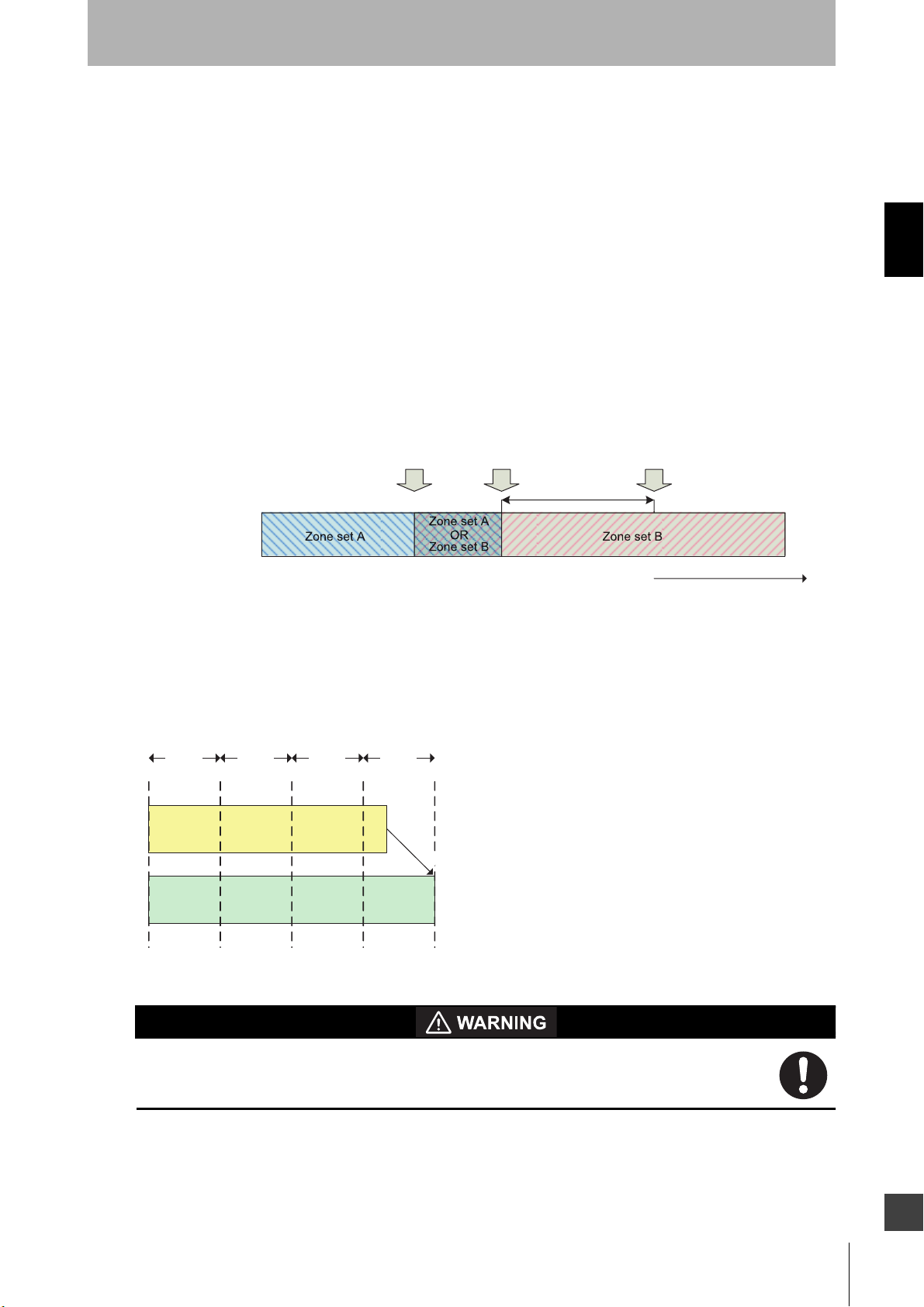
Operating States & Output Modes
tStartZoneB = tDangerZoneB - Tresponse
2) Zone Set Select Input Switch Timing - The worst case time it can take for switching zone set
select inputs. This time starts on the transition on the first input change and ends to the transition
on the last input change, this will be defined as Tswitches.
3) Zone Set Select Input Switch Tolerance - It is required that the zone set select input switching
circuitry begin switching the zone set inputs at a precise time relative to when the zone set
transition is desired to occur. The tolerance of timing when input state is actually switched,
generated by input switching circuitry, will be defined using +/- Ttol.
The simplest monitoring zone set switching timing in an installation is tEndZoneA < tStartZoneB. In this case,
the interval between tEndZoneA and tEndZoneA does not require any monitoring, thus switching from zone
set A to zone set B is straightforward. But when tEndZoneA = tStartZoneB or tEndZoneA > tStartZoneB, both zone set
A and zone set B may need to be monitored simultaneously. In such case, refer to How to Guarantee
Protection of Original Zone Set.
Chapter2
Monitoring zone set
Fig. 2-10 Switch from Zone set A to Zone set B.
t
EndZoneA
t
Zone set A
OR
Zone set B
StartZoneB
T
response
t
Zone set B Zone set A
DangerZoneB
time
The Zone Set Input Switch Timing must be configured to consider delay time of input switching circuitry
and ensure proper monitoring and safety. The configuration parameter Zone Set Switching Delay
(Tdelay) needs a value larger than Tswitches in increments of 20 ms (Tsample). In the following example,
Tdelay is configured to 80ms or more.
20 ms
20 ms 20 ms 20 ms
T
switches
T
delay
round up
Fig. 2-11 Zone Delay configuration.
If an insufficient Zone Delay is used for the actual worst case zone set select input
switching time of the installation, an unintended zone set may be temporarily enabled,
resulting in temporarily monitoring the wrong zone.
Also, it must be ensured that after a zone switch there is a minimum "hold time" before the next zone
switch can take place. That time is 2 * Tsample.
OS32C
User’s Manual
E
29
Page 52

Chapter2
Operating States & Output Modes
The Zone Input Switch Tolerance(Ttol) is the tolerance on when the zone switching circuitry is actually
able to start the switching of the inputs.
Besides Ttol and Tdelay, there is an additional delay of up to Tsample before the change on the zone set
select inputs is recognized.
Therefore, assuming switching of the inputs starts at tstart, the system is guaranteed to switch zones
between tmin = tstart + Tdelay - Ttol and tmax = tstart + Tdelay + Ttol + Tsample.
=
Zone set A
OR
Zone set B
t
start
Zone set BZone set A
T
sampl e
t
=
max
+
T
+
T
delay
Zone set switches
tol
(latest)
time
+
T
sampl e
Monitoring zone set
T
tol
start
T
delay
T
tol
t
Start
switching
Fig. 2-12 Zone set select input switching and zone set switch.
T
delay
t
min
t
+
T
start
delay-Ttol
Zone set switches
(earliest)
How To Configure Input Switch Circuitry Timing
Relative to tstart, the longest time it will take to begin monitoring Zone set B is tmax. When you take into
account the scanner's response time required to actually detect an object present in Zone set B, the
longest time to turning off the OSSDs relative to tstart can be shown as:
tmaxToOff = tmax + Tresponse
The critical timing guarantee to be met when changing zone sets is tDangerZoneB. The input switching
circuitry should begin switching the zone set select inputs prior to tDangerZoneB to ensure Zone B is
activated early enough to detect an object previously present in the zone set. The amount of time prior
to tDangerZoneB to start switching can be derived from tmaxToOff by equating it to tDangerZoneB.
tstart = tDangerZoneB - (Tresponse + Tdelay + Ttol + Tsample)
This means the switching circuitry must be configured to begin switching the inputs TmaxReaction before
tDangerZoneB to ensure safe monitoring of Zone set B, where
TmaxReaction = Tresponse + Tdelay + Ttol + Tsample
If tstart (switching start time) is configured without consideration of TmaxReaction (total maximum
reaction time), object detection within the new safety zone after switching and turning OFF
of the safety outputs may be delayed.
30
OS32C
User’s Manual
Page 53

Operating States & Output Modes
Zone set A
Zone set B
T
delay
t
=
min
t
+ T
start
delay-Ttol
Object detected
(earliest)
T
tol
t
start
Start
switching
T
tol
T
delay
Fig. 2-13 Object detection in Zone set B.
T
OR
extend
t
T
maxReaction
EndZoneA
T
sampl e
T
resp onse
Zone set BZone set A
t
start
T
Object detected
t
DangerZoneB
t
maxToOff
+ T
delay
resp onse
(latest)
+ T
=
+ T
sampl e
Chapter2
time
+
tol
From the diagram, there is a period of time, Textend. Between tmin and tEndZoneA, where the system may
have switched to Zone set B already but it needs to protect Zone set A. This is covered in the following
section.
How to Guarantee Protection of Original Zone Set
Additional measures may be necessary to ensure that Zone set A maintains adequate monitoring up to
tEndZoneA.
With tstart established relative to tDangerZoneB, we must compare tEndZoneA and tmin.
Case 1.
When tEndZoneA tmin, no further modifications are necessary. Zone set A will be properly monitored for
the duration that is needed.
Case 2. Zone set may be switched before the monitoring of zone set A is no longer required
When tEndZoneA > tmin, measures must be taken to ensure that Zone set A is protected even when the
monitoring zone is switched to zone set B before tEndZoneA. A simple measure is to modify safety
distance (S) used when defining Zone set A such that it includes an additional component (Zextra)
defined by the maximum approach speed (K) and a worst case extension time (Textend) to account for
the time that Zone set A may not be monitored.
Zone set switching after the monitoring of zone set A is no longer required
Zextra = K * Textend = K * (tEndZoneA - tmin)
(tEndZoneA tmin)
(tEndZoneA > tmin)
Expanding monitoring zone using this additional parameter Zextra enables the OS32C to detect an
object in advance that may enter the actual monitoring zone of zone set A during zone set switching. In
other words, expanding the monitoring zone means that the timing of tEndZoneA is shifted to tmin.
OS32C
User’s Manual
E
31
Page 54

Operating States & Output Modes
Zone set B
Chapter2
OS32C
Fig. 2-14 Zone A extension.
Zone set A Extension
Z
Danger Area
of Zone set A
extra
S
Zone set A
The extension of the safety distance around the entire protection zone will guarantee the safe
operation of the scanner. However, most installations may benefit from using the smallest possible
monitoring zone perimeter to maximize usable work space. For other measures, refer to Additional
Zone Set Switching Strategies on page 155.
32
OS32C
User’s Manual
Page 55

Chapter3
Getting Started 35
Installing Configuration Tool 35
How to Start 36
Description of Screen 37
Connection to the OS32C 41
Logging on to the OS32C 45
Changing Ethernet Configuration of OS32C 48
Basic Operation of Configuration
Tool
Chapter3
Menu 37
Tool Bars 39
Information Bar 40
Offline Mode 40
Connecting the PC and the OS32C 41
Forced DHCP mode 42
Changing the IP address of the PC (Windows XP) 42
Changing the IP address of the PC (Windows 7) 44
Changing the IP address of the PC (Windows 8.1 and Windows
10) 44
Detecting the OS32C on the network 45
Logging On 46
Logging OFF 46
Changing Password 46
Forgot the Password? 47
Receiving OS32C Configuration Information 49
Configuring New OS32C Property and Monitoring Zone 49
Default Configuration Settings 49
Creating a New Configuration 50
Import & Export Zone Coordinate Data 57
File Format 57
Importing Zone Coordinate Data 60
Exporting Zone Coordinate Data 62
Zone Set Selection and Configuration 64
Add a Zone 64
Copy and Paste Zones 65
Delete a Zone 67
Zone Set Input Selection 68
Editing Properties 69
Editing Monitor Zones 73
Sculpting & Reference Boundary Monitoring 76
Monitor Mode 81
Record System Monitoring 82
Playback System Monitoring 84
Read Fault Log 85
OS32C
User’s Manual
E
33
Page 56

Chapter3
Basic Operation of Configuration Tool
Window Calibration 86
Changing Options of Configuration Tool 88
Caution on Safety Zone Configuration 89
Reset to Default Configuration 90
34
OS32C
User’s Manual
Page 57

Basic Operation of Configuration Tool
Getting Started
The configuration and installation of an OS32C is a simple process. Here are the basic steps needed to get
started. Refer to the appropriate section of Chapter 3 for more information on any of these steps.
• Install the configuration tool
• Connect the OS32C to the same network as the computer
• Start the configuration tool
• Discover scanners on the network
• Log on to the OS32C
- Select Access Level
- Enter password
• Create new configuration
- Safety-critical parameters (EDM, response time, operating mode, zone sets, minimum object resolution
etc.)
- Non-safety-critical parameters (auxiliary output, warning output, power consumption mode, etc)
- Zone configuration
• Send configuration to the OS32C
Chapter3
Installing Configuration Tool
Installation of the configuration tool for the OS32C requires the following:
• Pentium 4 class 1.5GHz CPU or equivalent
• Windows XP, Windows 7, Windows 8.1 or Windows 10
• 512MB of RAM
• 10MB of available hard disk space
• Monitor with resolution of 1024 x 768 pixels or better.
Install the configuration tool based on the following steps:
1. Terminate all applications running.
2. Insert CD-ROM of the configuration tool to your CD drive.
3. Double-click the CD-ROM icon in My Computer to run Setup.exe.
4. Follow instructions of the installer program.
5. A program icon appears where you specified during installation.
To install the configuration tool on Windows XP Professional, Windows 7, Windows 8.1 or Windows 10, a user account of
Supervisor access level (Administrators) is required.
You can download the current version of configuration tool from the website below.
https://automation.omron.com/en/us/products/family/OS32C
OS32C
User’s Manual
E
35
Page 58

Chapter3
Basic Operation of Configuration Tool
How to Start
Select Start, All Programs, OS32C Configuration Tool, and OS32C Configuration Tool (if you have not
changed the program folder name).
Fig. 3-1 OS32C Configuration Tool
36
OS32C
User’s Manual
Page 59

Description of Screen
The configuration tool consists of the following:
Menu
File
New Used to create new configuration of OS32C
Open Opens a configuration information file saved on PC
Save
Save As Saves created configuration information on PC
Print Configuration Prints OS32C configuration information
Print Screen Snapshot Prints the zone information screen only with current window zoom
Exit Terminates the configuration tool
Table 3-1
Edit
Undo Undo last action
Redo Redo last action
Delete Selected Points Delete selected point(s) (Applies to polygon shaped zone)
Select a Group of Points Select a group of points (Applies to polygon shaped zone)
Copy Zone Copy the zone currently selected (in the Foreground pull-down menu).
Paste Zone
Circular Segment Convert zone being edited to a circular segment
Convert Shape to
Import Zone Data Import zone shape data from a textfile.
Discard Imported Zone Discard imported zone shape data.
Export Zone Data Export zone shape data to a textfile.
Table 3-2
Polygon Convert zone being edited to a polygon
Rectangle 180
Saves created configuration information on PC, or overwrites the existing configuration file if it was edited
Paste a copied zone to the zone currently selected (in the Foreground pull-down menu).
°
Convert zone being edited to a rectangle
Basic Operation of Configuration Tool
Chapter3
View
Tool Bar
Status Bar Shows or hides the status bar
View All Shows the zone information screen with minimum zoom
View Center Shows the zone information screen with OS32C in the center
Panning Enables/Disables view panning (Allow a user to click on the displayed zone and
Zoom In Magnifies the zone information screen
Zoom Out Minimizes the zone information screen
Zoom Window Magnifies a specified range of the zone information screen
Show/Hide Warning Zone 1 Shows or hides warning zone 1 in the zone information screen
Show/Hide Warning Zone 2 Shows or hides warning zone 2 in the zone information screen
Polar Coordinate View the monitoring zone using the polar coordinate system
Cartesian Coordinate View the monitoring zone using the cartesian coordinate system
Show/Hide Grid Shows or hides grid
Show/Hide Scale Shows or hides the scaling
Change Measurement Unit Change unit of measure. (mm, cm, or inches)
Flip view horizontally Changes the PC screen view in a horizontal direction
Flip view vertically Changes the PC screen view in a vertical direction
Reset flip view Reset the PC screen view to the default orientation
Table 3-3
Main Tool Bar Shows or hides the Main Tool Bar
Edit Tool Bar Shows or hides the Edit Tool Bar
move their mouse to adjust their view of the zone).
E
OS32C
User’s Manual
37
Page 60

Chapter3
Basic Operation of Configuration Tool
Configuration
Edit Properties Shows the configuration properties screen
Edit Zone Switches to the monitoring zone configuration mode
Add Zone Set Add a new zone to the configuration
Sculpting Enable/Disable sculpting mode
Receive from Sensor Receives current configuration information from the OS32C
All Changes Sends only the changed item(s) (safety and non-safety) to OS32C for registration
(available at Supervisor access level only)
Entire
Send to Sensor
/Enter CFG Mode
Register Changes/Exit CFG Mode Register the changed item(s) previously sent to OS32C and exit configuration mode.
Discard Changes/Exit CFG Mode Discard all changed item(s) previously sent to OS32C and/or exit configuration mode.
Configuration checksum View checksum for the current configuration
Reset to Default Configuration Reset the scanner back to manufacture default configuration (available at Supervisor
Table 3-4
Configuration
All Changes
(Non-Safety Only)
Entire
Configuration
(Non-Safety Only)
Sends all setup items (safety and non-safety) to OS32C for registration (available at
Supervisor access level only)
Sends only the changed item(s) of non-safety parameter(s) to OS32C for registration.
The user can select this option at Supervisor and Maintenance access levels.
Sends all setup items of non-safety parameter(s) to OS32C for registration. The user
can select this option at Supervisor and Maintenance access levels.
access level only)
Reference Boundary Monitoring
Disable Setting Disable reference boundary monitoring for the selected zone.
Set Point as Reference Boundary Set selected point(s) as reference boundary monitoring points.
Set Point as Non-reference
Boundary
Set All as Reference Boundary Set all points in the zone for reference boundary monitoring.
Set All as Non-reference Boundary Set none of the points in the zone for reference boundary monitoring.
Set Zone Tolerance Set the reference boundary monitoring tolerance for a zone.
Save Reference Boundary Setting Apply reference boundary monitoring settings to the zone.
Cancel Reference Boundary Setting Delete reference boundary monitoring settings.
Table 3-5
Un-set the selected point(s) as reference boundary monitoring point(s).
Utilities
Discover Sensors Find sensors on the network
Log On Used to log on to the OS32C
Log Off Used to log off from the OS32C
Change Sensor Name Change the name of the OS32C
Sensor Ethernet Configuration Change the IP address of the OS32C
Change Password Used to change the password
Read Encrypted Password Shows the encrypted password in case of lost password
Read Fault Log
System Information Display the system and ethernet configuration of the OS32C
Window Calibration Used after the window is replaced
System Monitoring
Record System Monitoring Record OS32C scanning zone information
Playback System Monitoring Playback previously recorded OS32C scanning zone information
Options Change configuration tool options
Table 3-6
Sensor Displays the fault log of the sensor block
I/O Block Display the fault log of the I/O block
Shows current OS32C scanning zone information on the zone information screen in
real-time
38
OS32C
User’s Manual
Page 61

Basic Operation of Configuration Tool
Tool Bars
(1) (2) (3) (4) (5) (6) (7) (8)
Fig. 3-2
(1) Create a new configuration Used to create new configuration of OS32C
(2) Open configuration from file Opens a configuration information file saved on PC
(3) Save configuration to file Saves created configuration information on PC
(4) Print configuration Prints OS32C configuration information
(5) System Monitoring Shows current scanning zone information on the zone information screen in real-time
(6) Sculpting Enable/disable sculpting mode
(7) Record system monitoring Record OS32C scanning zone information
(8) Playback system monitoring Playback previously recorded OS32C scanning zone information
Table 3-7
Chapter3
(1) (2) (3) (4) (5) (6) (7) (8) (9) (10) (11) (12) (13) (14) (15) (16) (17) (18)
Fig. 3-3
(1) Change measurement unit Change unit of measure (mm, cm, or inches)
(2) Zoom in Magnifies the zone information screen
(3) Zoom out Minimizes the zone information screen
(4) Zoom window Magnifies a specific area of the zone information screen
(5) View center Shows the zone information screen with the OS32C in the center
(6) View all Shows the zone information screen with minimum zoom
(7) Toggle view panning
(8) Edit zone Enables/Disables the editing of zones
(9) Convert shape to Convert zone being edited to a circular segment, polygon, or rectangle
(10) Undo Undo last action
(11) Redo Redo last action
(12) Add Zone Set Add a new zone to the configuration
(13) Copy zone Copy the zone currently selected (in the foreground).
(14) Paste zone Paste a copied zone to the zone currently selected (in the foreground).
(15) Flip view horizontally Changes the PC screen view in a horizontal direction
(16) Flip view vertically Changes the PC screen view in a vertical direction
(17) Reset flip view Reset the PC screen view to the default orientation
(18) Toggle rotation tool bar Show/Hide the rotation tool bar
Table 3-8
Enables/Disables view panning (Allow a user to click on the displayed zone and move
their mouse to adjust their view of the zone).
OS32C
User’s Manual
E
39
Page 62

Basic Operation of Configuration Tool
Information Bar
Chapter3
(5) (6)
(1) (2) (3)
Fig. 3-4
(1) Shows mouse position in polar coordinates (degrees)
(2) Shows mouse position in polar coordinates (radius)
(3) Shows mouse position in cartesian coordinates (x-axis)
(4) Shows mouse position in cartesian coordinates (y-axis)
(5) Shows unit of measure of mouse position
(6) Shows beam number of the mouse position
(7) Shows color of safety zone in the zone information screen
(8) Shows color of warning zone 1 in the zone information screen
(9) Shows color of warning zone 2 in the zone information screen
(10) Shows current logon access level
(11) When connected to an OS32C, displays the IP Address of the OS32C
Table 3-9
(4)
(7)
(8)
(9)
(10)
(11)
Offline Mode
In offline mode, a user can create, configure, and save a configuration to the PC, as well as load and
edit existing configurations on the PC. To enter offline mode, follow the steps shown below:
1. After the configuration tool is launched, the window shown below is displayed.
2. Click Cancel.
3. The configuration tool is launched in offline mode.
Fig. 3-5 Offine Configuration
40
OS32C
User’s Manual
Page 63

Basic Operation of Configuration Tool
Connection to the OS32C
This section describes how to connect a PC with the configuration tool and the OS32C.
The configuration tool is connected to the OS32C via Ethernet. An Ethernet cable with an M12, 4-pin
connector is required.
See page 119 for more details.
The default Ethernet configuration of the OS32C is DHCP mode (configuration to automatically obtain an IP
address).
When connecting a PC to the OS32C, different types of connections are available depending on the user's
environment. See the following examples according to your connection environment.
Connecting the PC and the OS32C
1. Physically connect the OS32C to the PC.
•For a direct connection, use an Ethernet cable to connect the OS32C directly to the Ethernet port
of the PC.
-- or --
•Use an Ethernet cable to connect the OS32C to the local area network of the PC.
Chapter3
On a network that limits the connection by MAC address authentication, etc., modify the settings to allow the OS32C
to connect to the network.
2. Configure the Ethernet settings of the PC and the OS32C so that they can communicate with each
other. There are two ways to do this:
•Configure both the PC and the OS32C to DHCP mode.
Set both the PC and the scanner to DHCP mode (both devices are set to obtain an IP address
automatically). If no DHCP server is present on the network, it will take approximately 40
seconds to establish the connection after connecting the PC to the OS32C. While the
connection is being established, the Local Area Connection icon on the system tray will look
like this:
Fig. 3-6 Connecting Icon
The configuration tool will not be able to connect to the OS32C while this icon is displayed.
A Limited Connection icon will be displayed after the connection icon on the system tray
disappears. The configuration tool will now be able to connect to the OS32C.
Fig. 3-7 Limited Connectivity
-- or --
•Configure both the PC and the OS32C to different fixed IP addresses on the same network.
OS32C
User’s Manual
E
41
Page 64

Chapter3
Basic Operation of Configuration Tool
A PC can be connected to the OS32C by configuring the PC to a different fixed IP address
within the same network as the IP address of the OS32C.
When connecting multiple OS32s to the network, it is recommended that a different fixed IP
address be used for each OS32C.
• Keep in mind that every time a change is made to the scanner, a reset of the scanner will be required,
which means the connection session between PC and scanner will have to be re-established.
• Consider the amount of time required for a reset of the OS32C when deciding which Ethernet settings to
use for the PC and the OS32C. When both PC and OS32C are set to DHCP mode, the time required for
resetting the scanner and re-establishing the ethernet connection between the two devices can be up to
55 seconds. When both PC and OS32C are configured with fixed IP addresses, the time required for
resetting the scanner and re-establishing the ethernet connection can be up to 15 seconds.
• When a device with the same IP address as the OS32C exists, a connection failure may occur. Be careful
not to have any duplicate IP addresses when connecting multiple OS32Cs to the network.
Forced DHCP mode
The OS32C can be temporarily forced into DHCP mode upon startup, regardless of the Ethernet
configuration settings of the OS32C.
1. Connect a PC directly to the scanner.
2. Press and hold the Start button while powering up the OS32C.
3. If the Start input is detected upon startup, the LEDs start blinking (this particular blinking does not
happen with a normal startup).
4. Once the blinking starts, release the Start button before 5 seconds have elapsed. If the release occurs
before 5 seconds, the OS32C enters forced DHCP mode.
5. Disconnect and reconnect the Ethernet cable to start automatic IP address acquisition.
6. Using the forced DHCP mode connects the PC with the DHCP mode and OS32C with the fixed IP
address setting.
As forced DHCP mode is a temporary mode, power cycle the OS32C to return the scanner to its fixed IP address.
Changing the IP address of the PC (Windows XP)
1. From the Control Panel, open Network Connections.
2. Right-click the Local Area Connection and select Properties.
3. Scroll-down and select Internet Protocol (TCP/IP).
42
OS32C
User’s Manual
Page 65

Basic Operation of Configuration Tool
4. With Internet Protocol (TCP/IP) highlighted, click Properties.
Chapter3
Fig. 3-8 Local Area Connection Properties
5. To set the PC to DHCP mode, select Obtain an IP Address automatically.
To set the PC to a fixed IP address, select Use the following IP address and specify the desired IP
address.
Fig. 3-9 TCP/IP Properties
OS32C
User’s Manual
E
43
Page 66

Chapter3
Basic Operation of Configuration Tool
6. When selecting Obtain DNS server address automatically, an alternate configuration can be set. To
set a fixed IP address for the alternate configuration, select Use the following IP address from the
Alternate Configuration tab. Set an IP address correctly according to the network environment. If you
do not set the IP address, select Automatic private IP address.
Fig. 3-10 Alternate Configuration
Changing the IP address of the PC (Windows 7)
1. Click the Start button, then click Control Panel.
2. In the search box, type adapter.
3. Under Network and Sharing Center, click View network connections.
4. Right-click on the connection to be changed, then select Properties. If prompted for an administrator
password, enter the password and confirm.
5. Select the Networking tab.
6. Select Internet Protocol Version 4 (TCP/IPv4) then click Properties.
7. To set the PC to DHCP mode, select Obtain an IP Address automatically.
To set the PC to a fixed IP address, select Use the following IP address and specify the desired IP
address.
Changing the IP address of the PC (Windows 8.1 and
Windows 10)
1. At the Search box (lower left corner of the desktop), type Network status.
2. Select Network status from the search result.
3. Select Change adapter options.
4. In the Network Connections window, right-click on the connection to be changed, then select
Properties. If prompted for an administrator password, enter the password and confirm.
5. Select the Networking tab.
6. Select Internet Protocol Version 4 (TCP/IPv4) then click Properties.
7. To set the PC to DHCP mode, select Obtain an IP Address automatically.
To set the PC to a fixed IP address, select Use the following IP address and specify the desired IP
address.
8. Press the OK button to close the window.
44
OS32C
User’s Manual
Page 67

Basic Operation of Configuration Tool
Logging on to the OS32C
There are 3 types of access levels:
• Operator Access Level (Operator)
To log on to the OS32C with this access level, a password is not required. This access level cannot make
changes to OS32C configurations. Only verification and monitoring of existing configuration is available.
• Maintenance Access Level (Maintenance)
To log on to the OS32C with this access level, a password is required. This access level allows a user to
modify the non-safety parameters only. This includes the warning zone shapes as well as the non-safety
critical parameters on page 52.
• Supervisor Access Level (Supervisor)
To log on to the OS32C with this access level, a password is required. This access level allows a user to
check, change and monitor OS32C configuration information.
Chapter3
NOTE: When planning to remotely log on to an OS32C that is located on a different subnet from the subnet of
the PC the following steps are needed during initial setup:
-The OS32C must have a dedicated password, the default password must be changed.
-The OS32C should be configured with a specific static IP address.
This will allow remote logon with full read/write access to the OS32C configuration.
Detecting the OS32C on the network
To connect to the OS32C using the configuration tool, the user needs to find the IP address of the
OS32C on the network. Select Discover Sensors from the Utilities menu.
Since the configuration tool is connected to the OS32C via Ethernet, Windows Security Alert is
displayed when Windows firewall is activated. Select Unblock. The alert will not be displayed once it is
unblocked.
Fig. 3-11 Windows Security Alert
OS32C
User’s Manual
E
45
Page 68

Chapter3
Basic Operation of Configuration Tool
Logging On
1. From Utilities menu, select Log On.
2. The Log On screen is displayed. Select an IP address of the OS32C to be connected.
Fig. 3-12 Logging On
3. Select User access level and enter a password. The initial password for the maintenance access level
is "mainusr". The initial password for the supervisor access level is "supeusr".
4. Click Continue.
5. When connected, the IP address and User access level of the OS32C are displayed.
Fig. 3-13 Logged On to Sensor
Logging OFF
From the Utilities menu, select Log OFF and click OK.
Changing Password
To limit access by an unauthorized user, the password may be changed. The user needs to log on to
the OS32C with the desired access level to change the password. At Supervisor access level,
passwords for Supervisor and Maintenance access levels can be changed. At Maintenance access
level, only password of this access level can be changed. No password change is permitted at
Operator access level. The following steps describe this process:
1. Log on to OS32C with the desired access level.
2. From the Utilities menu, select Change Password.
3. Enter the current password.
4. From Change Password, select an access level you want to change.
5. Enter the new password.
6. Enter the new password again for confirmation.
7. Click Change Password.
46
OS32C
User’s Manual
Page 69

Basic Operation of Configuration Tool
8. A confirmation message is displayed. Click Yes to change the password.
Fig. 3-14 Change User Password
The password must contain at least 4 but no more than 7 alphanumeric characters. The password is case-sensitive.
Forgot the Password?
Chapter3
If the password has been lost/forgotten, follow the steps shown below to acquire the password. This
procedure must be executed under the operator access level.
1. Log on with the Operator access level.
2. From the Utilities menu, select Read Encrypted Password.
3. Select Maintenance or Supervisor and click Read Password.
4. The encrypted password is displayed on the screen.
5. Contact Omron's sales representative with this character string.
OS32C
User’s Manual
E
47
Page 70

Chapter3
Basic Operation of Configuration Tool
Changing Ethernet Configuration of OS32C
1. From the Utilities menu, select Ethernet Configuration.
2. To configure the OS32C to DHCP mode, select Obtain an IP Address automatically. To configure the
OS32C to a fixed IP address, select Use the following IP address to specify an IP address. Set an IP
address correctly according to the network environment.
Fig. 3-15 Ethernet IP Address
3. Click Write to Sensor.
4. Confirm the change in Ethernet configuration. Click NO to abort the change.
5. The following window is displayed. Read the message and decide if you want to continue to use the
current IP address or start using the new address now.
Fig. 3-16 Ethernet Configuration
48
OS32C
User’s Manual
Page 71
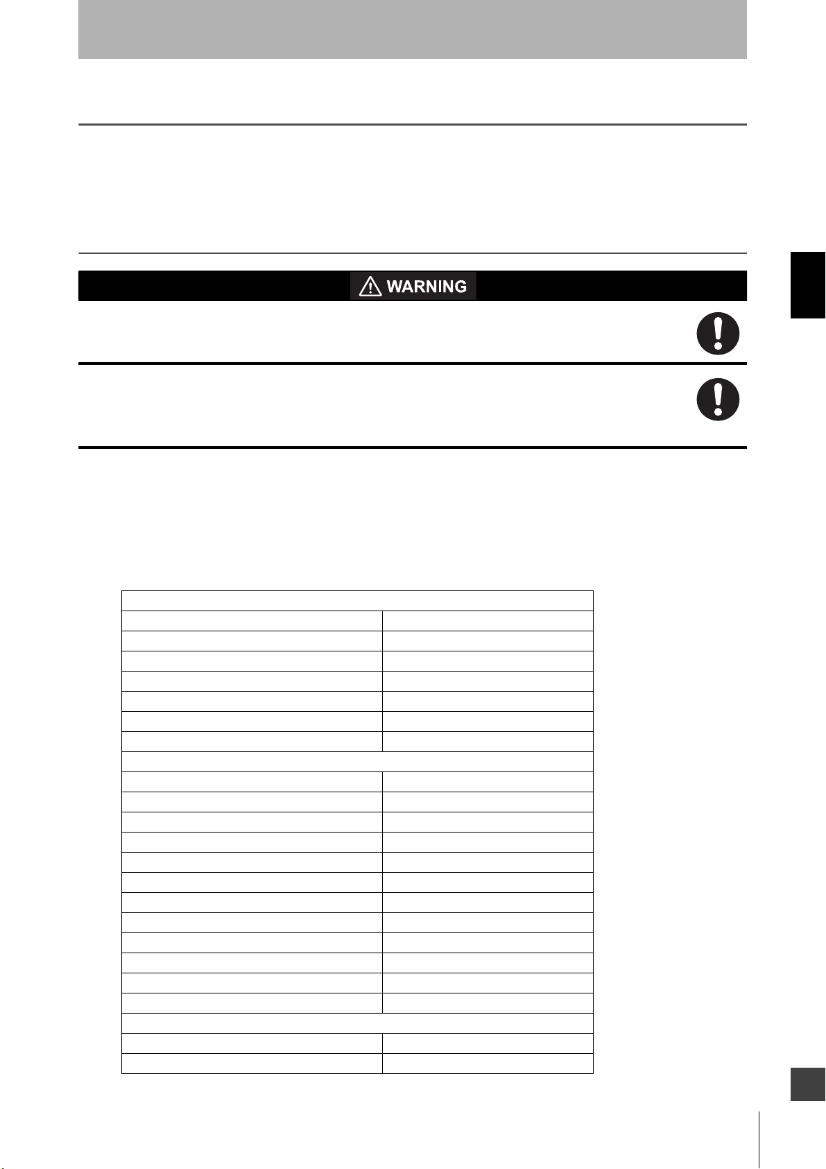
Basic Operation of Configuration Tool
Receiving OS32C Configuration Information
The configuration tool receives and displays current configuration information immediately upon connection to
the OS32C. Configuration information can be received manually as well. From Configuration menu, click
Receive from Sensor. Configuration information is retrieved from the sensor.
Configuring New OS32C Property and Monitoring Zone
To use the protective function of OS32C, a safety zone must be properly defined and configured.
If the response time is changed, re-calculation of the safety distance is required. This may require
re-configuration of the safety zones or re-installation of the OS32C. If the safety distance is not
appropriate for the application, the machine may not stop before the hazardous area is reached,
resulting in severe injuries.
This section describes how to configure a new monitoring zone or change the operating properties of the
OS32C using the configuration tool.
Default Configuration Settings
Safety Critical Parameters
External Device Monitoring Disable
Response time (ms) 80
Monitoring zone Zone 1
Zone delay (ms) 60
Operating mode Automatic Start
Minimum Object Resolution (mm) 70
Pollution tolerance mode Window Only
Non-Safety Critical Parameters
Restart delay (ms) 400
Auxiliary output mode Follow OSSD
Auxiliary output type PNP
Auxiliary output polarity Active ON
Warning output mode Follow OSSD
Warning output type PNP
Warning output polarity Active ON
Power reserve mode Disable
Seven-segment display Enable - Non-Inverted
ISI option Enable
ISI mode Follow safety zone
Warning zone selection by EIP (OS32C-xxx-DM) Disable
Safety Zone
Shape Circular segment
Radius (cm) 100
Chapter3
E
OS32C
User’s Manual
49
Page 72

Chapter3
Basic Operation of Configuration Tool
Scan angle (degrees) 270
Warning zone 1
Shape Circular segment
Radius (cm) 200
Scan angle (degrees) 270
Warning zone 2
Shape Circular segment
Radius (cm) 300
Scan angle (degrees) 270
Table 3-10 Default Settings
Creating a New Configuration
To change the configuration of the OS32C, a user must log on to the OS32C with the supervisor
access level.
1. From File menu, select New.
2. Enter a description for the configuration (up to 127 characters) and select applicable sensor model.
50
Fig. 3-17 Configuration Description
OS32C
User’s Manual
Page 73

3. New configuration screen is displayed.
Basic Operation of Configuration Tool
Chapter3
Fig. 3-18 New Configuration Parameters for OS32C-xxx
and OS32C-xxx-4M
• Safety Critical Parameters
1. External Device Monitoring (EDM) : When enabled the OS32C can monitor the N.C. contacts of the
external control relays. These relays are controlled by the
OSSD safety outputs.
2. Response Time : Configures a time period for OS32C safety output from ON to
OFF. The available range is from 80ms to 680ms in increments
of 40ms.
3. Monitoring Zone : To configure only one zone set, select Single zone. To
configure more than one zone, select Multiple zone.
4. Zone Delay : Select the desired Zone Delay. The available range is 20ms to
320ms in increments of 20ms.
5. Operating Mode : A user can select from Automatic Start, Start Interlock, or
Start/Restart Interlock.
6. Minimum Object Resolution : Select the minimum object size to be detected by the scanner.
Select from 3.0cm, 4.0cm, 5.0cm, and 7.0cm.
Fig.3-18b New Configuration Parameters for OS32C-xxxDM and OS32C-xxx-DM-4M
E
OS32C
User’s Manual
51
Page 74

Chapter3
Basic Operation of Configuration Tool
The minimum object resolution is displayed on the seven
segment display for 5 seconds on power up. Refer to "Status/
Diagnostic Display" in Chapter 2 for more detail.
7. Pollution Tolerance Mode (PTM) : A user can select from Disable, Window Only, and RBM Only.
• Non-Safety-Critical Parameters
1. Restart Delay : Select the desired OFF-to-ON delay when wiring the OS32C in
Automatic Start. Available range is 100ms to 60s, in increments
of 100ms.
2. Auxiliary Output Mode : Select either Disable, Follow OSSD, Indicate FAULT,
Warning Zone 1 infringed, Warning Zone 2 infringed, or
Window contaminated.
3. Auxiliary output type : Select PNP or NPN.
4. Auxiliary output polarity : Select Active ON or Active OFF.
5. Warning Output Mode : Select either Disable, Follow OSSD, Indicate FAULT,
Warning Zone 1 infringed, Warning Zone 2 infringed, or
Window contaminated.
6. Warning output type : Select PNP or NPN.
7. Warning output polarity : Select Active ON or Active OFF.
8. Power reserve mode : Select either Disabled or Standby mode.
9. Seven-segment display : Select Enable - Non-inverted, Disable, or Enable - Inverted.
When the display is inverted, a decimal will be displayed in the
corner. This display can be disabled to save power. Note: even
if the seven-segment display is disabled, the 4-digit code for
programming a scanner will still be displayed.
10. ISI option : Select Enable or Disable. When enabled, the ISIs will turn ON
to indicate the sector(s) where an intrusion has occured in a
safety or warning zone (depends on the ISI mode, see below).
11. ISI mode : Select Follow safety zone to have the ISIs light up to indicate
the sectors where an intrusion has occurred in the safety zone.
Select Follow warning zone to have the ISIs light up to
indicate the sector(s) where an intrusion has occured in a
warning zone.
12. Warning zone selection by EIP : Select Enable or Disable. When enabled, user can change the
warning zone selection via EtherNet/ IP. This parameter is
available for OS32C-DM version only.
13. Default configuration : Clicking this button resets the parameters to be configured
back to manufacturing default configuration.
52
The seven segment display can be inverted by selecting Enable - Inverted when the OS32C is installed upside down.
OS32C
User’s Manual
Page 75

Basic Operation of Configuration Tool
4. After configuration of parameters is finished, click Next.
Fig. 3-19 Zone Shape
Zone Shape: Select from Circular segment, Polygon, Semi-circle (180°), Rectangle (180°), and
Polygon (180°). Selecting Polygon automatically creates a shape with six segments.
This shape can be changed after finishing the wizard.
5. Click Next. If Multiple zones is selected, proceed to select zone shapes for the other zone(s).
Chapter3
6. The screen shown below is displayed. (In this example, a rectangle was selected for the safety zone, a
polygon was selected for warning zone 1, and a circular segment was selected for warning zone 2).
Fig. 3-20 Confirming Configuration
Safety and warning zones must be configured so that they are at least 100mm away from the wall at the range of 3 m
or less and at least 110 mm at the range greater than 3 m.
OS32C
User’s Manual
E
53
Page 76

Chapter3
Basic Operation of Configuration Tool
7. Different response times can be set to different zone sets and/or each individual zone within a zone
set.
To configure zone specific response times, click Edit response time from the configuration properties
screen (Fig. 3-20) .
Response time configuration window is displayed.
Fig. 3-21 Response Time setting
- Select zone set to configure response times.
- Select desired response time for each individual zone per zone set.
- Click "Apply to this zone set" to apply the new response time changes to the selected zone set. Or
select multiple zone sets and click "Apply to selected zone sets" to apply the new response time
changes to all selected zone sets.
- Click "View the setting for all zone sets" to verify the current response time setting for all available
zones.
- Click Save to accept or Cancel to ignore all changes made.
If the response time is changed, re-calculation of the safety distance is required. This may
require re-configuration of the safety zones or re-installation of the OS32C. If the safety
distance is not appropriate for the application, the machine may not stop before the
hazardous area is reached, resulting in severe injuries.
54
OS32C
User’s Manual
Page 77

Basic Operation of Configuration Tool
Saving OS32C Configuration to PC
You can save a configuration to the PC.
1. Simply go to File, Save As, and pick the location where you want to save your configuration.
Chapter3
Fig. 3-22 Save Configuration
The file will be saved as a ‘.cf3’ format.
The configuration data file extension is *.cf2 until Configuration Tool Version 1.8.0 and *.cf3 from Version 2.0.0.
E
OS32C
User’s Manual
55
Page 78

Chapter3
Basic Operation of Configuration Tool
2. To open the saved configuration, go to File, Open and locate the file you wanted to use.
.
Fig. 3-23 Open Configuration
56
OS32C
User’s Manual
Page 79

Basic Operation of Configuration Tool
Import & Export Zone Coordinate Data
This section describes how to modify a monitoring zone by importing coordinates from a comma delimited text
file. Monitoring zone coordinate data can also be exported to a text file for later use.
Monitoring zone parameters are subject to a number of constraints that include projective
consistency, maximum radius, and angle limits. As a result, the imported zone may not correspond
exactly to the zone defined in the file. The user must visually verify the imported zone when the
import process is complete. Refer to Checkout and Test Procedure Log on page 162.
File Format
In order for the OS32C Configuration Tool to properly import zone coordinate data, the data in the text
file (.txt) must be in the correct format:
Line Number
1 <File ID>
2 <Measurement Unit>
3 <Shape Type>
4 <DZS ID>,<Zone ID>
5 <Reserved>
6 <Coordinate Data>
7
8
Header
Data field
Chapter3
Fig. 3-24 File format
File ID: The first line of the file must always be 32001
Measurement unit: The second line of the text file indicates the measurement unit and must be set to
0, 1, or 2 where
0 = mm
1 = cm
2 = inches
Shape Type: The third line of the file must be set to 0, 1, or 2 where
0 = circular segment
1 = polygon
2 = rectangle
DZS ID 1 to 70. Boundary data will be imported to the specified DZS.
Zone ID 1 = safety zone, 2 = warning zone 1, 3 = warning zone 2
Reserved: Line 5 of the text file is reserved for future use. Set this line to 0
Coordinate Data: This data must start on line 6 of the text file and can span multiple lines, depending
on the zone shape:
Circular segment:
Data format: <radius>,<starting angle (degrees)>,<ending angle(degrees)>
E
OS32C
User’s Manual
57
Page 80

Chapter3
Basic Operation of Configuration Tool
Where the specified zone shape begins at <starting angle(degrees)> and moves in a counterclockwise direction and ends at <ending angle(degrees)>. Specifying a negative angle is permitted.
If the described zone falls within the area between 225° and 315°, the configuration tool will offer to
correct the zone so that the imported zone falls within the minimum and maximum angular
boundaries of the scanner.
Fig. 3-25 Circular segment
Here is an example of a file specifying a circular segment with 2000mm radius starting at 340° and
ending at 180°, It is designated to be written to the safety zone of zone set one.
Line Number
1 32001
20
30
4 1, 1
50
6 2000,340, 180
7
Fig. 3-26 Textfile for circular segment
58
OS32C
User’s Manual
Page 81

This text file would result in the following zone shape:
Radius = 2000mm
Basic Operation of Configuration Tool
180°
340°
Fig. 3-27 Circular segment from textfile
Polygon: This is specified by a list of XY coordinates of each vertex of the polygon. A minimum of 3
vertices must be specified, up to a maximum number of 677.
Data format: <x-coordinate>,<y-coordinate>
Here is an example of a file specifying a polygon with 5 vertices:
Line Number
1 32001
22
31
4 1, 1
Chapter3
50
6 -54.30,-23.78
7 -38.04,1.59
8 -23.10, 31.50
9 23.32,38.84
10 34.90,18.22
11
Fig. 3-28 Textfile for polygon shape
Rectangle:
Data format: <left width coordinate>,<right coordinate>,<depth>
Where:
Left width = -X direction (in the 2nd quadrant)
Right width coordinate = +X direction (1st quadrant)
Depth = +Y direction
Here is an example of a file specifying a rectangle with the width from -200.0cm to 125.5cm and a
depth of 200.4cm:
OS32C
User’s Manual
E
59
Page 82

Basic Operation of Configuration Tool
Line Number
1 32001
21
32
4 1, 1
Chapter3
50
6 -200.0, 125.5, 200.4
7
Fig. 3-29 Textfile for rectangle shape
This text file would result in the following zone shape:
-200.0
Fig. 3-30 Rectangle shape from textfile
125.5
200.4
Importing Zone Coordinate Data
1. Start the OS32C Configuration Tool
2. Create a new configuration or load an existing one
3. Select the destination zone where the zone coordinate data will be imported to, by selecting the zone
number and the desired safety or warning zone:
Fig. 3-31 Select Zone
4. From the Configuration menu select Edit Zone:
Fig. 3-32 Edit Zone
60
OS32C
User’s Manual
Page 83

Basic Operation of Configuration Tool
5. From the Edit menu select Import Zone Data:
Fig. 3-33 Import Zone Data
6. Locate and select the file with the data to be imported.
7. The configuration tool will import the data from the text file and check the validity of the data.
If the data in the text file is not valid the configuration tool will prompt the user to correct the text file and
try again.
The configuration tool will verify the zone data in the text file:
- is within minimum and maximum range of the zone being imported to
- is within the range allowed by the selected minimum object resolution
- has valid angular boundaries (does not fall within the area between 225° and 315°)
If these criteria are not met, the configuration tool will alert the user and offer to make corrections to the
specified zone in order to meet the requirements. Example error message:
Chapter3
Fig. 3-34 Confirm configuration tool suggested correction
8. The following message will indicate if any zones will be over-written. Example: If the current
configuration already contains DZS #2 and the text file also contains DZS #2 to be imported. The
process will overwrite the existing zones from DZS #2.
Fig. 3-35 Zones over-written
E
OS32C
User’s Manual
61
Page 84

Chapter3
Basic Operation of Configuration Tool
The following message will indicate the number of new zones to be added. If the current configuration
contains one DZS (3 zones) and the text file contains data for 69 DZS’s (207 zones). The process will
create new DZS’s to import the data.
Fig. 3-36 Zones to be added
Once the configuration tool has imported and displayed the zone, verify that the imported zone
displayed is correct. Click OK to accept the imported zone shape and use this shape for the zone
selected in step 3. Go to Edit and select Discard Imported Zone.
Fig. 3-37 Confirm imported zones
Exporting Zone Coordinate Data
1. Start the OS32C Configuration Tool
2. Create a new configuration or load an existing one
3. Select the zone to be exported, by selecting the zone number and the desired safety or warning zone:
Fig. 3-38 Select zone
4. From the Configuration menu select Edit Zone
Fig. 3-39 Edit Zone
62
OS32C
User’s Manual
Page 85

Basic Operation of Configuration Tool
5. From the Edit menu select Export Zone Data:
Fig. 3-40 Export Zone Data
6. Locate and select the file where the zone data is to be written to, or enter a new filename.
7. The configuration tool will export the zone dimensions/coordinates and save the data to the file
specified in the previous step.
8. Click OK after the configuration tool has completed exporting the data.
Chapter3
Fig. 3-41 Exporting zone data completed.
RBM ZONES cannot be exported into a text file, if they are included the following message will appear.
Fig. 3-42 RBM export not allowed
OS32C
User’s Manual
E
63
Page 86

Chapter3
Basic Operation of Configuration Tool
Zone Set Selection and Configuration
Once the number of zone sets is defined, the configuration tool is used to program the OS32C. Zone sets can
be added one at a time.
Add a Zone
1. Before adding a new zone, make sure Multiple Zone has been selected for the Monitoring Zone
parameter.
Fig. 3-43 Multi-zones
2. From the Configuration menu, select Add Zone Set.
Fig. 3-44 Add Zone
3. Confirm the zone shapes for the new zone.
64
Fig. 3-45 Confirm Zone Shapes
OS32C
User’s Manual
Page 87

Copy and Paste Zones
Copy & Paste a Single Zone
1. From the Configuration menu, select Edit zone.
2. Select the zone to be copied (bring it to the foreground)
3. Copy the zone by either:
a) selecting the Edit menu, then select Copy Zone, or
b) clicking the copy button on the toolbar.
4. Select the zone to paste to (bring it to the foreground)
5. Paste the zone by either:
a) selecting the Edit menu, then selecting Paste Zone, or
b) clicking the paste button on the toolbar.
- Safety zones can only be copied to other safety zones. Warning zones can only be copied to other warning zones.
- If reference boundary monitoring has been configured for a zone, it will not be copied over.
Basic Operation of Configuration Tool
Chapter3
OS32C
User’s Manual
E
65
Page 88

Chapter3
Basic Operation of Configuration Tool
Copy & Paste a Zone Set
To copy and paste a zone set (a safety zone and its corresponding two warning zones):
1. Select the destination zone number (bring to foreground).
2. Click on Define Zones tab.
3. While holding down the Ctrl key, use the left mouse button to drag and drop the desired zone set from
the Defined Zones tab, onto the destination zone.
Fig. 3-46 Drag and drop
In the above figure, zone set 2 is to be copied to zone set 1.
This method of drag and drop to copy and paste zone sets can also be used to copy and paste single zones (safety or
warning).
66
OS32C
User’s Manual
Page 89

Basic Operation of Configuration Tool
Delete a Zone
1. On the Defined Zones tab, right-click on the zone to be deleted.
2. Select Delete Zone.
Chapter3
Fig. 3-47 Delete Zone
OS32C
User’s Manual
E
67
Page 90

Chapter3
Basic Operation of Configuration Tool
Zone Set Input Selection
Once you have determined the number of zone sets required for your application, you will need to determine
the number of inputs you will use and the zone set select input states associated with each zone set. Fig. 3-48
illustrates the use of five inputs and how they apply to the five selected zones.
Left click on a light bulb to toggle it on/off to customize the zone input combos.
Click Verify Combos to check that zone input combos are valid and that there are no duplicates.
Click Default Combo to revert zone input combos to default combos.
The combination of required inputs can be customized by the installer. This configuration uses the recommended Default
combinations.
68
Fig. 3-48 Zone Set Select
OS32C
User’s Manual
Page 91

Basic Operation of Configuration Tool
Editing Properties
This section describes how to edit the properties of the OS32C such as response time and operating mode.
When transferring data from the PC to the OS32C and more than one OS32C is connected to the
network, it is necessary to visually check the diagnostic code on the status/diagnostic display. It is
recommended that the OS32C be installed in a position where the status/diagnostic display will be
visible.
Before sending the changes to the sensor, verify that the safety parameters are configured as
intended for the application.
1. From Configuration menu, click Edit Properties.
2. A configuration properties screen is displayed.
Chapter3
Fig. 3-49 Edit Properties
3. Edit the item to be changed.
4. After finishing the edits, from Configuration menu click Send to Sensor/Enter CFG Mode, All
Changes.
OS32C
User’s Manual
E
69
Page 92

Chapter3
Basic Operation of Configuration Tool
5. The screen shown below is displayed. Click Yes to confirm.
Fig. 3-50 Save Configuration to Sensor
6. When the configuration tool detects multiple scanners on a network, the user will be prompted to enter
a 4-digit code from the seven-segment display of the scanner being configured. The order in which
each two-digit pair is entered does not matter, and must be done within 120 seconds.
Fig. 3-51 Visual Scanner Identification
When the configuration tool detects only one scanner on the network, the user will be prompted to
confirm that the computer is connected to only one scanner. When this happens, the user will not need
to enter the 4-digit Visual Sensor Identification code when making changes to the scanner.
Fig. 3-52 Directly connected
70
OS32C
User’s Manual
Page 93

Basic Operation of Configuration Tool
7. A confirmation message is displayed, showing the changed configuration parameters. After careful
review click Confirm to accept.
Chapter3
Fig. 3-53 Configuration Confirmation
8. A message shown below is displayed for confirmation of zone configuration edits. Clicking Refresh
Scan Zone displays new scanning zone information of the OS32C on the screen. Click Yes to confirm
the configured zone. If a configured zone has not changed, this message will not appear.
Fig. 3-54 Confirming Zone Configuration
9. After transmission is finished, the window shown below is displayed. Click Yes to confirm. If you do not
want to register the configuration, click No.
Fig. 3-55 Write Configuration
OS32C
User’s Manual
E
71
Page 94

Chapter3
Basic Operation of Configuration Tool
10. The screen shown below is displayed while the OS32C resets.
Fig. 3-56 Reset
The configuration is now complete.
If writing cannot be done, wiring may be wrong. Refer to Chapter 5 to correct wiring.
72
OS32C
User’s Manual
Page 95

Basic Operation of Configuration Tool
Editing Monitor Zones
This section describes how to edit and register the changes made to the zone configurations to the OS32C.
1. From Configuration menu, click Edit Zones.
2. From Zone Set of the tool bar, select a zone set to edit. Then select a zone to edit from Foreground.
(In this example, Safety zone and Zone 1 are selcted.)
Chapter3
Fig. 3-57 Edit Zones
When a scanner enters zone configuration mode, the zone scanned by the OS32C is displayed. If you do not want to
display scanning zone information in the zone configuration mode, select Options from the Utility menu, and
unselect Shows scan zone in edit mode.
3. A monitoring zone can be edited by:
a) Moving a point
Click a point of the circular segment, polygon, or rectangle you want to move and drag it where you
want to place it.
b) Changing a zone shape
From Edit menu, select Convert Shape To. Select the new shape
c) Sculpting
Sculpting & Reference Boundary Monitoring p.76
d) Changing the scan angle
To change the scan/detection angle of a zone:
E
OS32C
User’s Manual
73
Page 96

Chapter3
Basic Operation of Configuration Tool
1. Select the zone to be changed.
2. From the Configuration menu, select Edit Zone.
3. Adjust the scan angle by moving either of the outermost points of the zone. In each of the figures
below, the two bottom-most points can be used to adjust the scan angle of the zone. The scan
angle can be as small as 45 deg. or as large as 270 deg.
Fig. 3-58 Circular Segment
Fig. 3-59 Polygon Shape
For polygon and sculpted shapes, the user can add or remove points from the zone shapes:
a) To add a point: double-click on the zone to add a point.
b) To add a point by specifying a coordinate:
i) Right-click on the zone and select Creating a point by coordinate
Fig. 3-60 Create a Point by Coordinate
ii) Specify the x-y coordinates for the location of the new point
74
Fig. 3-61 Specify x-y coordinates
OS32C
User’s Manual
Page 97

Basic Operation of Configuration Tool
iii) Click OK.
c) To change the location of a point by specifying a coordinate:
i) Right-click on the zone and select Editing by coordinate
Fig. 3-62 Edit a Point by Coordinate
ii) Select the point to be modified by selecting the point number from the pull-down menu. The
selected point will be circled.
Chapter3
Fig. 3-63 Specify x-y Coordinate
iii) Specify the new desired x-y coordinates for the selected point.
iv) Click OK.
d) To remove points:
i) From the Edit menu select Select a Group of Points. (This menu can also be accessed by
right-clicking on the zone).
ii) Use the mouse to select the desired point(s).
iii) From the Edit menu select Delete Selected Points.
4. When zone edit is finished, click Edit Zones from Configuration menu and verify if the checkbox is
being unselected. Now zone configuration is complete.
5. Send the configured zone information to the OS32C for registration. From Configuration menu, click
Send to Sensor/Enter CFG Mode, All Changes. Configure by following instructions on a displayed
message.
6. Reset the OS32C by following the prompts.
Configuration is now complete.
Safety and warning zones must be configured so that they maintain a distance of 100mm from the wall or fixtures at the range
of 3 m or less and at least 110 mm at the range greater than 3 m.
OS32C
User’s Manual
E
75
Page 98

Chapter3
Basic Operation of Configuration Tool
Sculpting & Reference Boundary Monitoring
The scanning zone information from the OS32C can be used for zone configuration. The desired safety zone
can be traced within the scanning range of the OS32C. Zone configuration based on this data is called
sculpting.
To configure a zone with sculpting, follow the steps shown below.
1. From the Configuration menu, select Sculpting.
2. The sculpting data displayed on the screen is based on the scanning information sent from the OS32C.
Move an object (such as a test piece) around the perimeter of the zone under configuration. The
position where the object is detected closest to the OS32C is used as the sculpting data.
Fig. 3-64 Sculpting Mode
3. To redo the configuration, exit sculpting mode by clicking the Cancel button on the Save Sculpting
Data window, and re-entering sculpting mode.
Fig. 3-65 Save Sculpting Data Window
4. If sculpting data displayed on the screen is correct, select the zone to which the configured sculpting
data is to be assigned by using the pull-down menus in the Save Sculpting Data window. Click the
Save or Edit Zone button.
76
OS32C
User’s Manual
Page 99

Basic Operation of Configuration Tool
5. To enable Reference Bounding Monitoring (RBM), select the desired zone for RBM and then click the
Start RBM Sculpting button.
6. The scanner will then take approximately 50 seconds to measure the boundary. It is important not to
change the boundary during this time since the scanner will be re-scanning the area and taking an
average of the distances.
Fig. 3-66 Learning the Boundary
Chapter3
Fig. 3-67 Learning the Boundary Complete
7. Select the points to be used for RBM:
a. To select all the points in the zone for RBM
•Right-click on the display screen and select Set All as Reference Boundary.
Fig. 3-68 Set All as Reference Boundary
OS32C
User’s Manual
E
77
Page 100

Chapter3
Basic Operation of Configuration Tool
b. To select a group of points to be used for RBM:
•Right-click on the display screen and select Select a Group of Points.
Fig. 3-69 Select Group of Points
•Right-click on the display screen again and select Set Point as Reference Boundary.
78
Fig. 3-70 Set Points as Reference Boundary Points
•Repeat as needed.
c. To cancel RBM for the zone,
•Right-click on the display screen and select Set All as Non-Reference Boundary and select Save
Reference Boundary Setting.
Fig. 3-71 Cancel RBM Settings
OS32C
User’s Manual
 Loading...