

Page 1
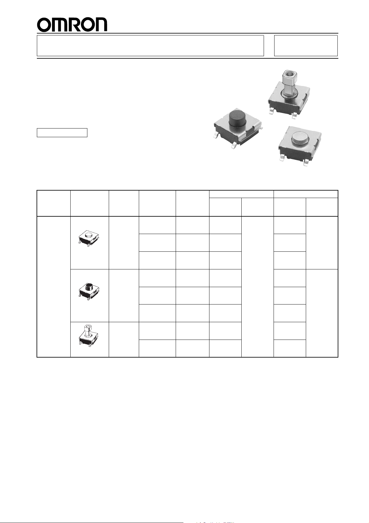
Surface-mounting Switches Ideal for
(Flat type)
(Flat type)
(Projected type)
High-density Mounting
• Tape packing style also available
• Allows reflow soldering
• 3 actuator heights for design flexibility; Projected
plunger versions allow installation of B32-series
keytops
RoHS Compliant
■ List of Models
B3FS Tactile Switch (SMT)
Type Plunger type Height Operating
6 × 6 mm
B3FS-1000
models
Note: Order in multiples of the minimum order unit. Switches are not sold individually.
3.1 mm 0.98 N {100 gf} Black B3FS-1000 100 B3FS-1000P 3,000
4.3 mm 0.98 N {100 gf} Black B3FS-1010 B3FS-1010P 1,000
7.3 mm 0.98 N {100 gf} Black B3FS-1050 B3FS-1050P
force (OF)
1.47 N {150 gf} Ivory B3FS-1002 B3FS-1002P
2.55 N {260 gf} Blue B3FS-1005 B3FS-1005P
1.47 N {150 gf} Ivory B3FS-1012 B3FS-1012P
2.55 N {260 gf} Blue B3FS-1015 B3FS-1015P
1.47 N {150 gf} Yellow B3FS-1052 B3FS-1052P
Plunger
color
Model Quantity
Bag Embossed taping
per
package
Model Quantity
per
package
1
Page 2

■ Ratings/Characteristics
Ratings 1 to 50 mA, 5 to 24 VDC (resistive load)
Ambient operating temperature -25°C to +70°C at 60%RH max. (with no icing or condensation)
Ambient operating humidity 35% to 85% (at +5 to +35°C)
Contact form SPST-NO
Contact resistance 100 mΩ max. (initial value) (rated: 1 mA, 5 VDC)
Insulation resistance 100 MΩ min. (at 100 VDC)
Dielectric strength 250 VAC, 50/60 Hz for 1 min
Bounce time 5 ms max.
Vibration resistance Malfunction: 10 to 55 Hz, 1.5-mm double amplitude
Shock resistance
Durability Standard models (0.98 N {100 gf}): 1,000,000 operations min.
Weight B3FS-1000: Approx. 0.2 g
■ Operating Characteristics
Item 0.98 N 1.47 N 2.55 N
Operating force (OF) 0.98±0.29 N
Releasing force (RF) 0.2 N {20 gf} min. 0.49 N {50 gf} min. 0.49 N {50 gf} min.
Pretravel (PT)
{100±30 gf}
+0.2
0.25
Destruction: 1,000 m/s2 {approx. 100G} max.
Malfunction: 100 m/s2 {approx. 10G} max.
High-force models (1.47 N {150 gf}): 300,000 operations min.
High-force models (2.55 N {260 gf}): 100,000 operations min.
B3FS-1000
/
−0.1
1.47±0.49 N
{150±50 gf}
mm
2.55±0.69 N
{260±70 gf}
B3FSB3FS
2
Page 3

■ Dimensions (Unit: mm)
(Bottom View)
2
4
1
3
PCB Pad
(Top View)
(One-side PCB t= 1.6)
Terminal Arrangement/
Internal Connection
(Top View)
4.5±
0.2
3 dia.
8
0.7 0.7
6.3
3.1±
0.2
2.6
9.6
6.4
3.1 5.9
3
1
4
2
4.5±
0.2
3 dia.
8
0.7 0.7
6.3
4.3
2.6
9.6
6.4
3.1 5.9
3
1
4
2
4.5±
0.2
6
8
2.4±
0.1
0.7 0.7
6.3
3.1
1.8
7.3
2.6
9.6
6.4
3.1 5.9
3
1
4
2
Flat Type
B3FS-1000
B3FS-1002
B3FS-1005
B3FS-1000P
B3FS-1002P
B3FS-1005P
PCB Pad
(Top View)
(One-side PCB t= 1.6)
Terminal Arrangement/
Internal Connection
(Top View)
PCB Pad
(Top View)
(One-side PCB t= 1.6)
Terminal Arrangement/
Internal Connection
(Top View)
Flat Type
B3FS-1010
B3FS-1012
B3FS-1015
B3FS-1010P
B3FS-1012P
B3FS-1015P
Projected Type
B3FS-1050
B3FS-1052
B3FS-1050P
B3FS-1052P
Note: The numbers used for terminals in the following graphics are indicated in the “Bottom View” diagram below. In this
diagram, the Switch is rotated so that the terminals are on the right and left-hand sides, and the OMRON logo appears
the right way up.
B3FSB3FS
Note: Unless otherwise specified, a tolerance of ±0.4 mm applies to all dimensions. No terminal numbers are indicated on the Switches.
■ Key Tops
B32-series Special Key Tops are available for projected plunger models. Refer to the Datasheet of B32 for details.
■ Precautions
Be sure to read the safety precautions common to all Tactile Switches for correct use.
3
Page 4

B3FSB3FS
• Application examples provided in this document are for reference only. In actual applications, confirm equipment functions and safety before using the product.
• Consult your OMRON representative before using the product under conditions which are not described in the manual or applying the product to nuclear control systems, railroad
systems, aviation sy
stems, vehicles, combustion systems, medical equipment, amusement machines, safety equipment, and other systems or equipment that may have a serious
influence on lives and property if used improperly. Make sure that the ratings and performance characteristics of the product provide a margin of safety for the system or
equipment, and b
e sure to provide the system or equipment with double safety mechanisms.
OMRON Corporation
ELECTRONIC AND MECHANICAL COMPONENTS COMPANY
Contact: www.omron.com/ecb
Cat. No. A113-E1-04
0812(0207)(O)
Note: Do not use this document to operate the Unit.
4
 Loading...