

Page 1

Thank you for choosing this OMNUC FND-X-series product.
This manual provides details on the installation, wiring, troubleshooting, and maintenance of
OMNUC
FND-X-series
products along with parameter settings for the operation of the products.
S Make
S Retain this manual for future reference.
S This
S Specifications and functions may change without notice to improve product performance.
S Forward
sure that actual users of this product will read this manual thoroughly and handle and operate the prod
uct with care.
manual describes the specifications
sume that nothing described in this manual is possible.
and reverse rotation of AC Servomotors described
the
output shaft of the motor as follows: counterclockwise rotation is forward and clockwise rotation is reverse.
and functions of the product and relations with other products. As
in this manual are defined as looking at the end of
General Instructions
1. Refer to Precautions first and carefully read and be sure to understand the information provided.
2. Familiarize
motor and Servo Driver for proper use.
3. The
Servomotor
4. We
recommend that you add the following precautions to any instruction manuals you prepare for
the system into which the product is being installed.
S Precautions on the dangers of high-voltage equipment.
S Precautions on touching the terminals of the product even after power has been turned OFF.
(These terminals are live even with the power turned OFF.)
5. Do
not perform withstand voltage
internal components.
6. Servomotors
hand and to consider the operating environment and other conditions affecting the service life.
7. Do not set any parameter not described in this manual, otherwise the Servomotor or Servo Driver
may malfunction. Contact your OMRON representatives if you have any inquiry.
yourself with this manual
and Servo Driver must be wired and operated by experts in electrical engineering.
and Servo Drivers have a finite service life. Be sure to keep replacement products on
and understand the functions and performance of the Servo
or other megameter tests on the product. Doing so may damage
-
-
-
NOTICE
Before using the product under the following conditions, consult your OMRON representatives, make
sure
that the ratings and performance characteristics of the product are good enough for the systems,
machines,
mechanisms.
1. Conditions not described in the manual.
2. The application of the product to nuclear control systems, railroad systems, aviation systems, ve-
3. The
or equipment, and be sure to provide the systems, machines, or equipment with double safety
hicles, combustion systems, medical equipment, amusement machines, or safety equipment.
application of the product to systems,
on human life and property if they are used improperly.
machines, or equipment that may have a serious influence
Items to Check After Unpacking
Check the following items after removing the product from the package:
S Has the correct product been delivered (i.e., the correct model number and specifications)?
S Has the product been damaged in shipping?
The product is provided with Safety Precautions Sheets. No connectors or mounting screws are
provided.
Page 2
USER’S MANUAL
OMNUC FND-X SERIES
MODELS FND-Xj (DIO Type)
FND-Xj-SRT (CompoBus/S Type)
POSITION DRIVERS
Page 3

No. 6182
OMRON Corporation
Read and Understand this Manual
Please read and understand this manual before using the product. Please consult your OMRON
representative if you have any questions or comments.
Warranty and Limitations of Liability
WARRANTY
OMRON's exclusive warranty is that the products are free from defects in materials and workmanship for a
period of one year (or other period if specified) from date of sale by OMRON.
OMRON MAKES NO WARRANTY OR REPRESENTATION, EXPRESS OR IMPLIED, REGARDING NONINFRINGEMENT, MERCHANTABILITY, OR FITNESS FOR PARTICULAR PURPOSE OF THE
PRODUCTS. ANY BUYER OR USER ACKNOWLEDGES THAT THE BUYER OR USER ALONE HAS
DETERMINED THAT THE PRODUCTS WILL SUITABLY MEET THE REQUIREMENTS OF THEIR
INTENDED USE. OMRON DISCLAIMS ALL OTHER WARRANTIES, EXPRESS OR IMPLIED.
LIMITATIONS OF LIABILITY
OMRON SHALL NOT BE RESPONSIBLE FOR SPECIAL, INDIRECT, OR CONSEQUENTIAL DAMAGES,
LOSS OF PROFITS OR COMMERCIAL LOSS IN ANY WAY CONNECTED WITH THE PRODUCTS,
WHETHER SUCH CLAIM IS BASED ON CONTRACT, WARRANTY, NEGLIGENCE, OR STRICT
LIABILITY.
In no event shall the responsibility of OMRON for any act exceed the individual price of the product on which
liability is asserted.
IN NO EVENT SHALL OMRON BE RESPONSIBLE FOR WARRANTY, REPAIR, OR OTHER CLAIMS
REGARDING THE PRODUCTS UNLESS OMRON'S ANALYSIS CONFIRMS THAT THE PRODUCTS
WERE PROPERLY HANDLED, STORED, INSTALLED, AND MAINTAINED AND NOT SUBJECT TO
CONTAMINATION, ABUSE, MISUSE, OR INAPPROPRIATE MODIFICATION OR REPAIR.
1
Page 4

No. 6182
Application Considerations
SUITABILITY FOR USE
OMRON shall not be responsible for conformity with any standards, codes, or regulations that apply to the
combination of products in the customer's application or use of the products.
At the customer's request, OMRON will provide applicable third party certification documents identifying
ratings and limitations of use that apply to the products. This information by itself is not sufficient for a
complete determination of the suitability of the products in combination with the end product, machine,
system, or other application or use.
The following are some examples of applications for which particular attention must be given. This is not
intended to be an exhaustive list of all possible uses of the products, nor is it intended to imply that the uses
listed may be suitable for the products:
• Outdoor use, uses involving potential chemical contamination or electrical interference, or conditions or
uses not described in this manual.
• Nuclear energy control systems, combustion systems, railroad systems, aviation systems, medical
equipment, amusement machines, vehicles, safety equipment, and installations subject to separate
industry or government regulations.
• Systems, machines, and equipment that could present a risk to life or property.
Please know and observe all prohibitions of use applicable to the products.
NEVER USE THE PRODUCTS FOR AN APPLICATION INVOLVING SERIOUS RISK TO LIFE OR
PROPERTY WITHOUT ENSURING THAT THE SYSTEM AS A WHOLE HAS BEEN DESIGNED TO
ADDRESS THE RISKS, AND THAT THE OMRON PRODUCTS ARE PROPERLY RATED AND INSTALLED
FOR THE INTENDED USE WITHIN THE OVERALL EQUIPMENT OR SYSTEM.
PROGRAMMABLE PRODUCTS
OMRON shall not be responsible for the user's programming of a programmable product, or any
consequence thereof.
2
Page 5

No. 6182
Disclaimers
CHANGE IN SPECIFICATIONS
Product specifications and accessories may be changed at any time based on improvements and other
reasons.
It is our practice to change model numbers when published ratings or features are changed, or when
significant construction changes are made. However, some specifications of the products may be changed
without any notice. When in doubt, special model numbers may be assigned to fix or establish key
specifications for your application on your request. Please consult with your OMRON representative at any
time to confirm actual specifications of purchased products.
DIMENSIONS AND WEIGHTS
Dimensions and weights are nominal and are not to be used for manufacturing purposes, even when
tolerances are shown.
PERFORMANCE DATA
Performance data given in this manual is provided as a guide for the user in determining suitability and does
not constitute a warranty. It may represent the result of OMRON's test conditions, and the users must
correlate it to actual application requirements. Actual performance is subject to the OMRON Warranty and
Limitations of Liability.
ERRORS AND OMISSIONS
The information in this manual has been carefully checked and is believed to be accurate; however, no
responsibility is assumed for clerical, typographical, or proofreading errors, or omissions.
3
Page 6

Notice:
OMRON products are manufactured for use according to proper procedures by a qualified
operator and only for the purposes described in this manual.
The following conventions are used to indicate and classify precautions in this manual. Always heed the information provided with them. Failure to heed precautions can result in injury to people or damage to property.
DANGER Indicates
!
or serious injury.
WARNING Indicates
!
or serious injury.
Caution Indicates
!
or moderate injury, or property damage.
an imminently hazardous situation which, if not avoided, will
a potentially hazardous situation which, if not avoided, could result in death
a potentially hazardous situation which, if not avoided, may result in minor
OMRON Product References
All OMRON products are capitalized in this manual. The word “Unit” is also capitalized when
it refers to an OMRON product, regardless of whether or not it appears in the proper name
of the product.
The abbreviation “Ch,” which appears in some displays and on some OMRON products,
often means “word” and is abbreviated “Wd” in documentation in this sense.
The abbreviation “PC” means Programmable Controller and is not used as an abbreviation
for anything else.
result in death
Visual Aids
The following headings appear in the left column of the manual to help you locate different
types of information.
Note Indicates information of particular interest for efficient and convenient operation of the product.
OMRON, 1998
All rights reserved. No part of this publication may be reproduced, stored in a retrieval system, or transmitted,
in any form, or by any means, mechanical, electronic, photocopying, recording, or otherwise, without the prior
written permission of OMRON.
No patent liability is assumed with respect to the use of the information contained herein. Moreover
OMRON is constantly striving to improve its high-quality products, the information contained in this manual
is subject to change without notice. Every precaution has been taken in the preparation of this manual. Nevertheless, OMRON assumes no responsibility for errors or omissions. Neither is any liability assumed for dam
ages resulting from the use of the information contained in this publication.
, because
-
Page 7

General Precautions
Observe the following precautions when using the OMNUC Position Drivers and peripheral
devices.
This manual may include illustrations of the product with protective covers removed in order
to describe the components of the product in detail. Make sure that these protective covers
are on the product before use.
Consult your OMRON representative when using the product after a long period of storage.
WARNING Do not touch the inside of the Servo Driver. Doing so may result in electric shock.
!
WARNING Always
!
to
in electric shock.
WARNING Do
!
items while the power is being supplied. Doing so may result in electric shock.
WARNING Operation,
!
Not doing so may result in operation stoppage, burning of the product, electric
shock, or injury.
WARNING Wiring
!
supply. Doing so may result in electric shock.
WARNING Do
!
Doing so may result in electric shock.
WARNING Do not touch the rotating parts of the Servomotor under operation. Doing so may
!
result in injury.
WARNING Do
!
connect the frame ground terminals of the Servo Driver and the Servomotor
a class-3 ground (to 100 Ω or less). Not connecting to
not remove the front cover
maintenance, or inspection must be performed by authorized personnel.
or inspection must be performed
not damage, pull on, apply stress to, place heavy objects on, or pinch the cables.
not modify the product. Doing so may result in injury or damage to the
, terminal covers, cables, Parameter Units, or optional
at least 1 minute after turning of
a class-3 ground may result
f the power
product.
Caution Use the Servomotors and Servo Drivers in a specified combination. Not doing so
!
may result in fire or damage to the products.
Caution Do
!
Caution Do not touch the Servo Driver radiator, regenerative resistor, or Servomotor while
!
not store or install the product in the following places. Doing so may result in elec
tric shock, fire or damage to the product.
S Locations subject to direct sunlight.
S Locations subject to temperatures or humidity outside the range specified in the
specifications.
S Locations
S Locations subject to corrosive or flammable gases.
S Locations subject to dust (especially iron dust) or salts.
S Locations subject to shock or vibration.
S Locations subject to exposure to water, oil, or chemicals.
the
power is being supplied or soon after the power is turned of
in a skin burn due to the hot surface.
subject to condensation as the result of severe changes in
f. Doing
temperature.
so may result
-
Page 8

Storage and Transportation Precautions
Caution Do not hold by the cables or motor shaft while transporting the product. Doing so
!
may result in injury or malfunction.
Caution Do
!
Caution Use
!
not place any load exceeding the figure indicated on the product.
result in injury or malfunction.
the motor eye-bolts
porting the machinery may result in injury or malfunction.
only for transporting the Servomotor
Installation and Wiring Precautions
Caution Do
!
Caution Do
!
Caution Be
!
Caution Provide
!
not step on or place a heavy object on the
not cover the inlet or outlet ports and prevent any foreign objects from entering
the product. Doing so may result in fire.
sure to install the product in the correct direction. Not doing so may result in mal
function.
the specified clearances between the Servo Driver and the
with other devices. Not doing so may result in fire or malfunction.
Doing so may
. Using them for trans
product. Doing so may result in injury
control panel or
-
.
-
Caution Do not apply any strong impact. Doing so may result in malfunction.
!
Caution Be sure to wire correctly and securely. Not doing so may result in motor runaway,
!
injury, or malfunction.
Caution Be
!
Caution Use crimp terminals for wiring. Do not connect bare stranded wires directly to the
!
Caution Use
!
Caution Take
!
Caution Install
!
sure to firmly tighten the screws fixing the product,
Not doing so may result in malfunction.
terminal block. Doing so may result in fire.
the power supply voltages specified in this manual. Not doing so may result in
burning.
appropriate
is
supplied. Be particularly careful in places where the power supply is unstable. Not
doing so may result in damage to the product.
external breakers and take other safety measures against short-circuiting in
external wiring. Not doing so may result in fire.
measures to ensure that the specified power with the rated voltage
the terminal block, and cables.
Page 9

Caution Provide an appropriate stopping device on the machine side to secure safety. (A
!
holding
injury.
brake is not a stopping device
for securing safety
.) Not doing so may result in
Caution Provide
!
operation and power interruption. Not doing so may result in injury.
Caution Take
!
lowing locations. Not doing so may result in equipment damage.
S Locations subject to static electricity or other forms of noise.
S Locations subject to strong electromagnetic fields and magnetic fields.
S Locations subject to possible exposure to radioactivity.
S Locations close to power supplies.
an external emergency stopping device that allows an instantaneous stop
appropriate and suf
ficient
countermeasures when installing systems in the fol
Operation and Adjustment Precautions
Caution Confirm that no adverse effect will occur in the system before performing the test
!
operation. Not doing so may result in equipment damage.
Caution Check
!
Not doing so may result in equipment damage.
Caution Do not make any extreme adjustments or setting changes. Doing so may result in
!
unstable operation and injury.
the newly
set parameters for proper execution before actually running them.
of
-
Caution Separate the Servomotor from the machine, check for proper operation, and then
!
connect to the machine. Not doing so may cause injury.
Caution When an alarm occurs, remove the cause, reset the alarm after confirming safety,
!
and then resume operation. Not doing so may result in injury.
Caution Do
!
Caution Do
!
not come close to the machine immediately after resetting
terruption to avoid an unexpected restart. (Take appropriate measures to secure
safety against an unexpected restart.) Doing so may result in injury.
not use the built-in brake
result in malfunction.
of the Servomotor for ordinary braking. Doing so may
momentary power in
Maintenance and Inspection Precautions
WARNING Do not attempt to take the Unit apart or repair. Doing either of these may result in
!
electrical shock or injury.
Caution Resume
!
quired for operation. Not doing so may result in equipment damage.
operation only after transferring to the new Unit the
contents of the data re
-
-
Page 10
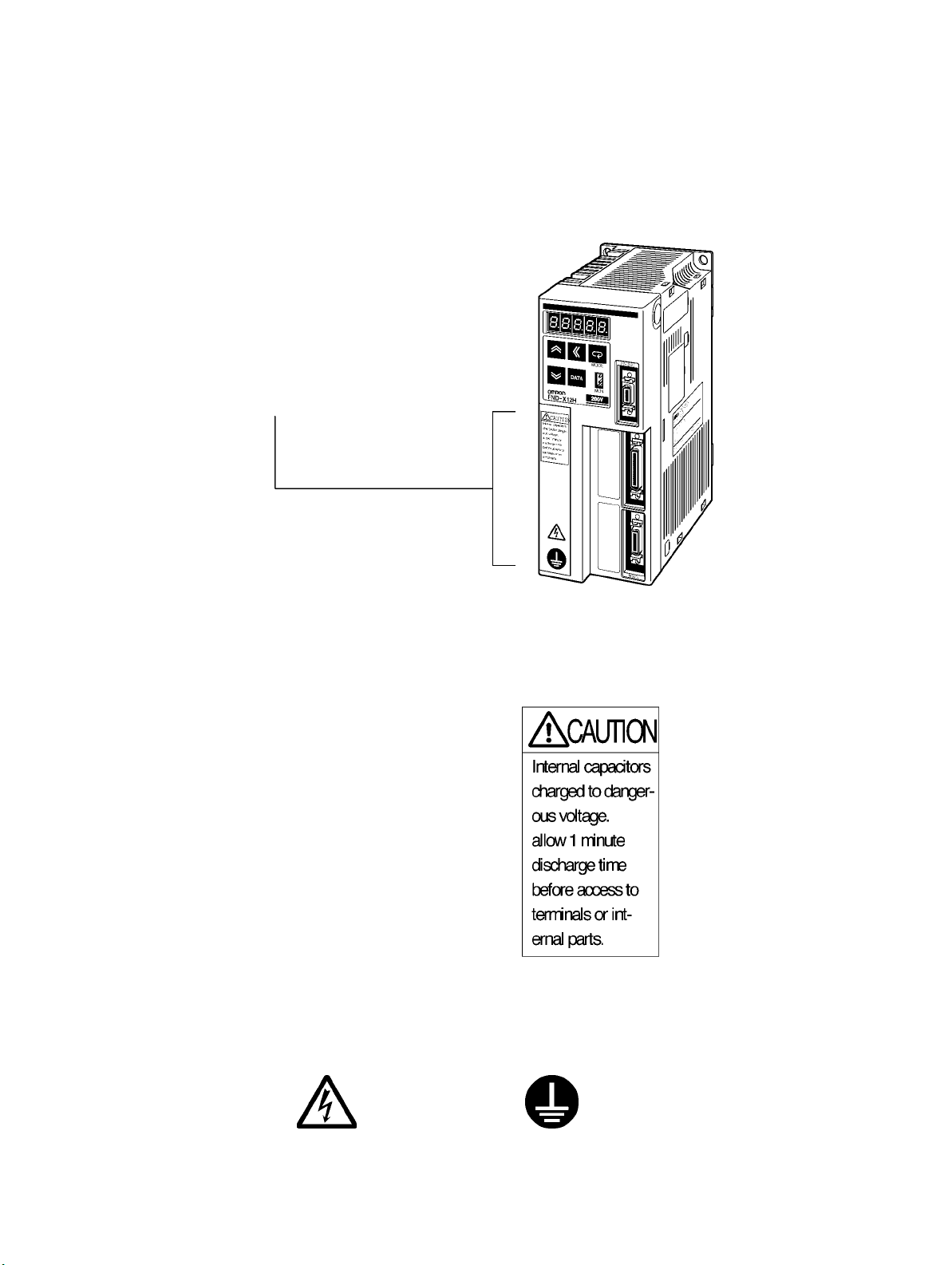
Warning Labels
Warning labels are pasted on the product as shown in the following illustration. Be sure to
follow the instructions given there.
Warning
labels
Warning Labels
Warning
label 1
W
arning label 2
May cause electric shock.
Connect to a ground of 100
Ω or less.
Page 11
VISUAL INDEX
For users who wish to begin operations quickly.
- The
OMNUC FND-X-series Position Driver allows motor test operation
and motor without connecting the controller. Read
play
,
properly set the motor model code, and then operate the
Check Mode
Do not connect any load (machines) when performing test operation. Perform test operation
only after confirming that no adverse effects will be caused by test operation.
.
3-2 Turning ON Power and Checking Dis-
motor according to
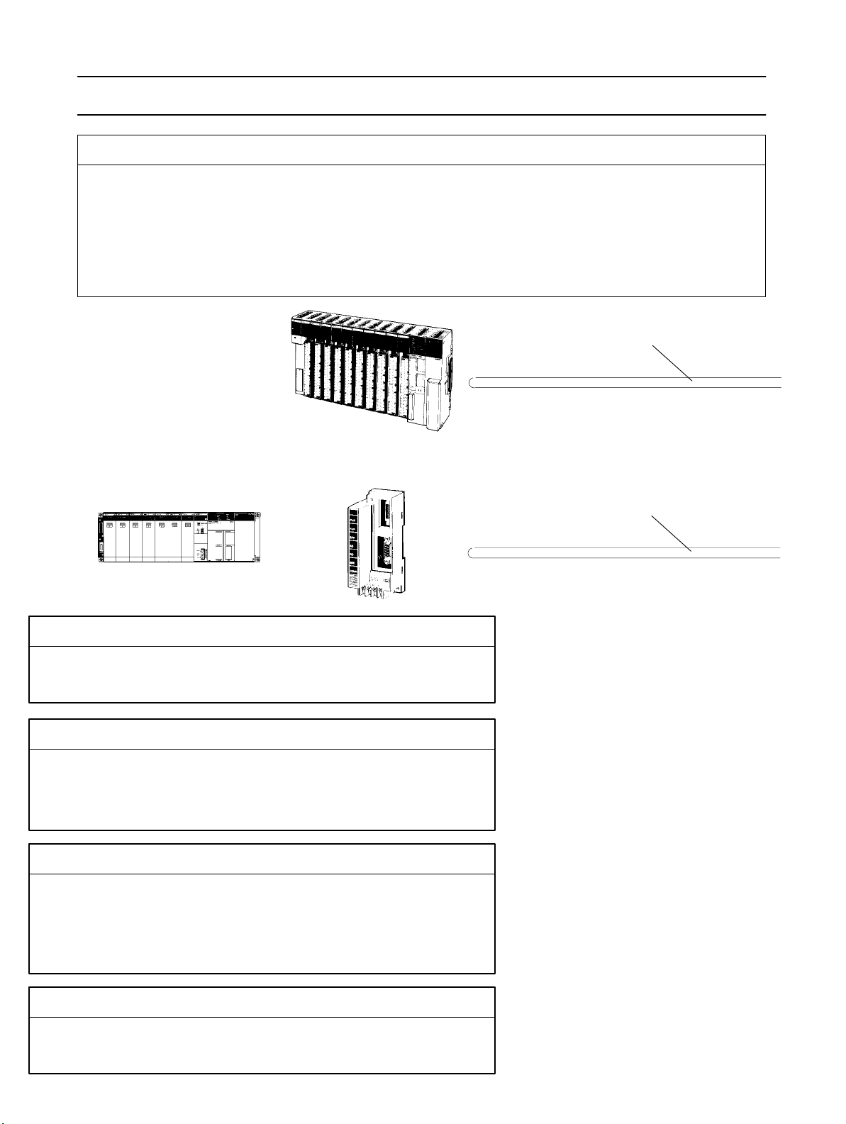
SYSMAC C/CV
Programmable Controller
I/O signals
SYSMAC C200H-HX/HG/HE
or CQM1 Programmable
Controller
SRM1-C01/-C02
Master Controller
Section 6 CompoBus/S Specifications
CompoBus/S signals
only by wiring the driver
3-8-2System
5-3-1 General Control
Cable Specifications
Initial Operation (Starting)
- 3-1 Operation Procedure
- 3-2Turning ON Power and Checking Displays
Function Settings (Parameter Settings)
- 3-4 Setting Functions: User Parameters (H Parameters)
- 3-5 Position Control Settings (PTP Parameters)
- 3-6 Setting Positioning Data (PTP Data, Direct Input)
Trial Operation and Adjustments
- 3-8-1 Trial Operation Procedure
- 3-8-2 System Check Mode
- 3-9-1 Auto-tuning
- 3-9-2 Manually Adjusting Gain
Troubleshooting
- 4-4 Protection and Diagnosis
- 4-5 Troubleshooting
Page 12
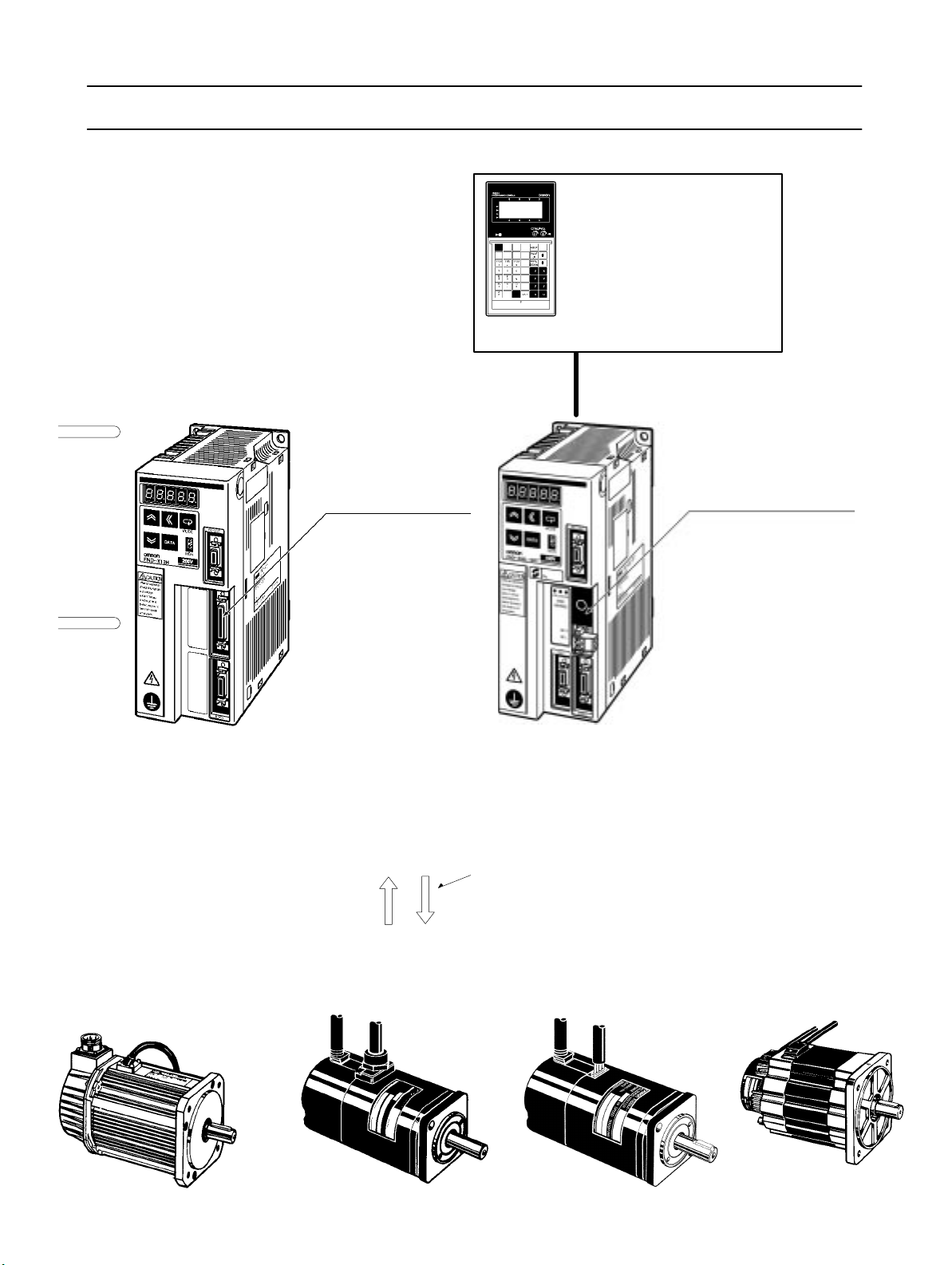
OMNUC FND-X Series
Teaching Box
CVM1-PRO01 Teaching Box
ROM Cassette:
CVM1-MP702
(Common for MC Units and
Position Drivers)
CVM1-MP703
For details refer to Cat. No. W354-E1.
RS-422 Teaching Box connections cable
OMNUC FND-X-series Position Drivers
2-2-2 Control Circuitry
Terminal Wiring
DIO Type
200 V: FND-XjjH
100 V: FND-XjjL
5-1 Position Driver Specifications
2-2-3 Wiring Terminal Blocks
3-3-3 Mode Details
6-3 Connecting a CompoBus/S
System
CompoBus/S Type
200 V: FND-XjjH-SRT
100 V: FND-XjjL-SRT
OMNUC M-series
AC Servomotors
1200
r/min: 200 to 1.8 kW with Resolver
2000 r/min: 200 to 2.2 kW with Resolver
4000 r/min: 60 to 2 kW with Resolver
OMNUC U-series
AC Servomotors
3000 r/min: 30 to 2 kW with
Incremental Encoder
3000 r/min: 30 to 2 kW with
Absolute Encoder
5-3 Cable Specifications
Encoder/Resolver signalsPower signals
OMNUC U-UE-series
AC Servomotors
3000
r/min: 100 to 750 W with
Incremental Encoder
OMNUC H-series
AC Servomotors
3000 r/min: 50 to 1
Incremental Encoder
100 W with
Page 13

Table of Contents
Chapter 1. Introduction .
1-1 Functions . . . . . . . . . . . . . . . . . . . . . . . . . . . . . . . . . . . . . . . . . . . . . . . . . . . . . . . . . . . . . . . . . .
1-2 Nomenclature and Key Operations . . . . . . . . . . . . . . . . . . . . . . . . . . . . . . . . . . . . . . . . . . . . . .
1-3 Supported Standards and Supporting Models . . . . . . . . . . . . . . . . . . . . . . . . . . . . . . . . . . . . . .
1-3-1 Standards Supported by Position Drivers . . . . . . . . . . . . . . . . . . . . . . . . . . . . . . . . . . .
1-3-2 Standards Supported by AC Servomotors . . . . . . . . . . . . . . . . . . . . . . . . . . . . . . . . . .
Chapter
2-1 Installation . . . . . . . . . . . . . . . . . . . . . . . . . . . . . . . . . . . . . . . . . . . . . . . . . . . . . . . . . . . . . . . . .
2-2 Wiring . . . . . . . . . . . . . . . . . . . . . . . . . . . . . . . . . . . . . . . . . . . . . . . . . . . . . . . . . . . . . . . . . . . .
Chapter
3-1 Operational Procedure . . . . . . . . . . . . . . . . . . . . . . . . . . . . . . . . . . . . . . . . . . . . . . . . . . . . . . . .
3-2 Turning ON Power and Checking Displays . . . . . . . . . . . . . . . . . . . . . . . . . . . . . . . . . . . . . . .
3-3 Using the Display Area . . . . . . . . . . . . . . . . . . . . . . . . . . . . . . . . . . . . . . . . . . . . . . . . . . . . . . .
3-4 Setting Functions: User Parameters (H Parameters) . . . . . . . . . . . . . . . . . . . . . . . . . . . . . . . . .
3-5 Position Control Settings (PTP Parameters) . . . . . . . . . . . . . . . . . . . . . . . . . . . . . . . . . . . . . . .
3-6 Setting Positioning Data (PTP Data, Direct Input) . . . . . . . . . . . . . . . . . . . . . . . . . . . . . . . . . .
3-7 Operational Sequence . . . . . . . . . . . . . . . . . . . . . . . . . . . . . . . . . . . . . . . . . . . . . . . . . . . . . . . .
3-8 Trial Operation . . . . . . . . . . . . . . . . . . . . . . . . . . . . . . . . . . . . . . . . . . . . . . . . . . . . . . . . . . . . . .
2. Design and Installation. . . . . . . . . . . . . . . . . . . . . . . . . . . .
2-1-1 External Dimensions (Unit: mm) . . . . . . . . . . . . . . . . . . . . . . . . . . . . . . . . . . . . . . . . .
2-1-2 Installation Conditions . . . . . . . . . . . . . . . . . . . . . . . . . . . . . . . . . . . . . . . . . . . . . . . . .
2-2-1 Overview . . . . . . . . . . . . . . . . . . . . . . . . . . . . . . . . . . . . . . . . . . . . . . . . . . . . . . . . . . . .
2-2-2 Control Circuitry Terminal Wiring . . . . . . . . . . . . . . . . . . . . . . . . . . . . . . . . . . . . . . . .
2-2-3 Wiring Terminal Blocks . . . . . . . . . . . . . . . . . . . . . . . . . . . . . . . . . . . . . . . . . . . . . . . .
2-2-4 Wiring for Noise Resistance . . . . . . . . . . . . . . . . . . . . . . . . . . . . . . . . . . . . . . . . . . . . .
2-2-5 Wiring Products Conforming to EMC Directives . . . . . . . . . . . . . . . . . . . . . . . . . . . .
2-2-6 Peripheral Device Connection Examples . . . . . . . . . . . . . . . . . . . . . . . . . . . . . . . . . . .
2-2-7 Battery Wiring and Encoder Setup for Absolute Encoder . . . . . . . . . . . . . . . . . . . . . .
3. Operation. . . . . . . . . . . . . . . . . . . . . . . . . . . . . . . . . . . . . . .
3-2-1 Items to Check Before Turning ON the Power . . . . . . . . . . . . . . . . . . . . . . . . . . . . . .
3-2-2 Turning ON the Power and Checking the Display . . . . . . . . . . . . . . . . . . . . . . . . . . . .
3-3-1 Key Operations . . . . . . . . . . . . . . . . . . . . . . . . . . . . . . . . . . . . . . . . . . . . . . . . . . . . . . .
3-3-2 Modes and Mode Changes . . . . . . . . . . . . . . . . . . . . . . . . . . . . . . . . . . . . . . . . . . . . . .
3-3-3 Mode Details . . . . . . . . . . . . . . . . . . . . . . . . . . . . . . . . . . . . . . . . . . . . . . . . . . . . . . . . .
3-3-4 CompoBus/S Communications Display and Setting Panel . . . . . . . . . . . . . . . . . . . . .
3-4-1 Setting User Parameters and H Parameters . . . . . . . . . . . . . . . . . . . . . . . . . . . . . . . . .
3-4-2 User Parameter and H Parameter Tables . . . . . . . . . . . . . . . . . . . . . . . . . . . . . . . . . . .
3-4-3 User Parameter and H Parameter Details . . . . . . . . . . . . . . . . . . . . . . . . . . . . . . . . . . .
3-5-1 Setting PTP Parameters (PP-01 to PP-26) . . . . . . . . . . . . . . . . . . . . . . . . . . . . . . . . . .
3-5-2 PTP Parameters (PP-01 to PP-26) . . . . . . . . . . . . . . . . . . . . . . . . . . . . . . . . . . . . . . . .
3-5-3 PTP Parameter Details (PP-01 to PP-26) . . . . . . . . . . . . . . . . . . . . . . . . . . . . . . . . . . .
3-6-1 Setting PTP Data (When UP-01 is 11 or 12) . . . . . . . . . . . . . . . . . . . . . . . . . . . . . . . .
3-6-2 Setting Direct Input (When UP-01 is 13 or 14) . . . . . . . . . . . . . . . . . . . . . . . . . . . . . .
3-6-3 PTP Data (Pd01jj to Pd64j) . . . . . . . . . . . . . . . . . . . . . . . . . . . . . . . . . . . . . . . . . .
3-6-4 PTP Data Details (Pdjjj) . . . . . . . . . . . . . . . . . . . . . . . . . . . . . . . . . . . . . . . . . . . .
3-7-1 Origin Search . . . . . . . . . . . . . . . . . . . . . . . . . . . . . . . . . . . . . . . . . . . . . . . . . . . . . . . .
3-7-2 Origin Teaching . . . . . . . . . . . . . . . . . . . . . . . . . . . . . . . . . . . . . . . . . . . . . . . . . . . . . .
3-7-3 Teaching . . . . . . . . . . . . . . . . . . . . . . . . . . . . . . . . . . . . . . . . . . . . . . . . . . . . . . . . . . . .
3-7-4 Point Positioning (UP-01: 11 or 12) . . . . . . . . . . . . . . . . . . . . . . . . . . . . . . . . . . . . . . .
3-7-5 Direct Positioning (UP-01: 13 or 14) . . . . . . . . . . . . . . . . . . . . . . . . . . . . . . . . . . . . . .
3-8-1 Trial Operation Procedure . . . . . . . . . . . . . . . . . . . . . . . . . . . . . . . . . . . . . . . . . . . . . .
3-8-2 System Check Mode . . . . . . . . . . . . . . . . . . . . . . . . . . . . . . . . . . . . . . . . . . . . . . . . . . .
. . . . . . . . . . . . . . . . . . . . . . . . . . . . . . . . . . . .
Page 14

Table of Contents
3-9 Making Adjustments . . . . . . . . . . . . . . . . . . . . . . . . . . . . . . . . . . . . . . . . . . . . . . . . . . . . . . . . .
3-9-1 Auto-tuning . . . . . . . . . . . . . . . . . . . . . . . . . . . . . . . . . . . . . . . . . . . . . . . . . . . . . . . . . .
3-9-2 Manually Adjusting Gain . . . . . . . . . . . . . . . . . . . . . . . . . . . . . . . . . . . . . . . . . . . . . . .
3-9-3 Adjustment Parameter Details . . . . . . . . . . . . . . . . . . . . . . . . . . . . . . . . . . . . . . . . . . .
3-10 Regenerative Energy Absorption . . . . . . . . . . . . . . . . . . . . . . . . . . . . . . . . . . . . . . . . . . . . . . . .
3-10-1 Calculating Regenerative Energy . . . . . . . . . . . . . . . . . . . . . . . . . . . . . . . . . . . . . . . . .
3-10-2 Position Driver Absorbable Regenerative Energy . . . . . . . . . . . . . . . . . . . . . . . . . . . .
3-10-3 Regenerative Energy Absorption by Regeneration Resistor . . . . . . . . . . . . . . . . . . . .
Chapter
4-1 Monitor Mode . . . . . . . . . . . . . . . . . . . . . . . . . . . . . . . . . . . . . . . . . . . . . . . . . . . . . . . . . . . . . .
4-2 Check Mode . . . . . . . . . . . . . . . . . . . . . . . . . . . . . . . . . . . . . . . . . . . . . . . . . . . . . . . . . . . . . . . .
4-3 Monitor Output . . . . . . . . . . . . . . . . . . . . . . . . . . . . . . . . . . . . . . . . . . . . . . . . . . . . . . . . . . . . .
4-4 Protection and Diagnosis . . . . . . . . . . . . . . . . . . . . . . . . . . . . . . . . . . . . . . . . . . . . . . . . . . . . . .
4-5 Troubleshooting . . . . . . . . . . . . . . . . . . . . . . . . . . . . . . . . . . . . . . . . . . . . . . . . . . . . . . . . . . . . .
4-6 Periodic Maintenance . . . . . . . . . . . . . . . . . . . . . . . . . . . . . . . . . . . . . . . . . . . . . . . . . . . . . . . .
Chapter
5-1 Position Driver Specifications . . . . . . . . . . . . . . . . . . . . . . . . . . . . . . . . . . . . . . . . . . . . . . . . . .
5-2 Servomotor Specifications . . . . . . . . . . . . . . . . . . . . . . . . . . . . . . . . . . . . . . . . . . . . . . . . . . . . .
5-3 Cable Specifications . . . . . . . . . . . . . . . . . . . . . . . . . . . . . . . . . . . . . . . . . . . . . . . . . . . . . . . . .
4. Application. . . . . . . . . . . . . . . . . . . . . . . . . . . . . . . . . . . . . .
4-2-1 I/O Signal Status . . . . . . . . . . . . . . . . . . . . . . . . . . . . . . . . . . . . . . . . . . . . . . . . . . . . . .
4-4-1 Alarms . . . . . . . . . . . . . . . . . . . . . . . . . . . . . . . . . . . . . . . . . . . . . . . . . . . . . . . . . . . . . .
4-4-2 Countermeasures to Alarms . . . . . . . . . . . . . . . . . . . . . . . . . . . . . . . . . . . . . . . . . . . . .
4-4-3 CompoBus/S-type Position Driver Protective and Diagnostic Functions . . . . . . . . . .
4-4-4 Overload Characteristics . . . . . . . . . . . . . . . . . . . . . . . . . . . . . . . . . . . . . . . . . . . . . . . .
4-4-5 Alarm Output and Clearing Alarms . . . . . . . . . . . . . . . . . . . . . . . . . . . . . . . . . . . . . . .
4-5-1 Preliminary Inspection . . . . . . . . . . . . . . . . . . . . . . . . . . . . . . . . . . . . . . . . . . . . . . . . .
4-5-2 Precautions . . . . . . . . . . . . . . . . . . . . . . . . . . . . . . . . . . . . . . . . . . . . . . . . . . . . . . . . . .
4-5-3 Replacing the Position Driver and the Motor . . . . . . . . . . . . . . . . . . . . . . . . . . . . . . . .
4-5-4 Troubleshooting . . . . . . . . . . . . . . . . . . . . . . . . . . . . . . . . . . . . . . . . . . . . . . . . . . . . . .
5. Specifications. . . . . . . . . . . . . . . . . . . . . . . . . . . . . . . . . . . .
5-1-1 General Specifications (Common to DIO, CompoBus/S) . . . . . . . . . . . . . . . . . . . . . .
5-1-2 Performance Specifications . . . . . . . . . . . . . . . . . . . . . . . . . . . . . . . . . . . . . . . . . . . . .
5-1-3 I/O Specifications . . . . . . . . . . . . . . . . . . . . . . . . . . . . . . . . . . . . . . . . . . . . . . . . . . . . .
5-2-1 U-series 30-W to 750-W Servomotors (INC/ABS) . . . . . . . . . . . . . . . . . . . . . . . . . . .
5-2-2 U-UE-series Servomotors . . . . . . . . . . . . . . . . . . . . . . . . . . . . . . . . . . . . . . . . . . . . . . .
5-2-3 U-series 1-kW to 2-kW Servomotors (INC/ABS) . . . . . . . . . . . . . . . . . . . . . . . . . . . .
5-2-4 H-series Servomotors . . . . . . . . . . . . . . . . . . . . . . . . . . . . . . . . . . . . . . . . . . . . . . . . . .
5-2-5 M-series Servomotors . . . . . . . . . . . . . . . . . . . . . . . . . . . . . . . . . . . . . . . . . . . . . . . . . .
5-3-1 General Control Cables (DIO Position Drivers Only) . . . . . . . . . . . . . . . . . . . . . . . . .
5-3-2 Connector Terminal Board Conversion Unit Cables (DIO Position Drivers Only) . . .
5-3-3 External Control Signal Connecting Cables (CompoBus/S Position Drivers Only) . .
5-3-4 Encoder Cables . . . . . . . . . . . . . . . . . . . . . . . . . . . . . . . . . . . . . . . . . . . . . . . . . . . . . . .
5-3-5 Resolver Cables . . . . . . . . . . . . . . . . . . . . . . . . . . . . . . . . . . . . . . . . . . . . . . . . . . . . . .
5-3-6 Power Cables . . . . . . . . . . . . . . . . . . . . . . . . . . . . . . . . . . . . . . . . . . . . . . . . . . . . . . . .
Chapter
6-1 CompoBus/S Configuration Requirements . . . . . . . . . . . . . . . . . . . . . . . . . . . . . . . . . . . . . . . .
6-2 CompoBus/S Communications Specifications . . . . . . . . . . . . . . . . . . . . . . . . . . . . . . . . . . . . .
6-3 Connecting a CompoBus/S System . . . . . . . . . . . . . . . . . . . . . . . . . . . . . . . . . . . . . . . . . . . . . .
6. CompoBus/S Specifications. . . . . . . . . . . . . . . . . . . . . . . . .
Page 15

Table of Contents
Chapter 7. Appendices .
7-1 Standard Models . . . . . . . . . . . . . . . . . . . . . . . . . . . . . . . . . . . . . . . . . . . . . . . . . . . . . . . . . . . .
7-2 Parameter Settings Tables . . . . . . . . . . . . . . . . . . . . . . . . . . . . . . . . . . . . . . . . . . . . . . . . . . . . .
. . . . . . . . . . . . . . . . . . . . . . . . . . . . . . . . . . . . .
Revision History . . . . . . . . . . . . . . . . . . . . . . . . . . . . . . . . .
Page 16

1
Chapter 1
Introduction
1-1 Functions
1-2 Nomenclature and Key Operations
1-3 Supported Standards and Supporting Models
Page 17

Introduction Chapter 1
1-1 Functions
OMRON’s FND-X Position Drivers are servo drivers with built-in positioner functions
that control AC servomotors according to positioning data.
H FND-X-Series Models
There are two types of FND-X Position Drivers, according to the type of control signals used.
Control signals Model
DIO FND-XjjH/FND-XjjL
CompoBus/S FND-XjjH-SRT/FND-XjjL-SRT
Up to eight CompoBus/S Position
output points. Two-wire communications are used, reducing system wiring. High-speed communications are also achieved, with a communications cycle time of 0.5 or 0.8 ms.
Note Only the high-speed communications mode is available with the FND-X.
Drivers can be connected to one Master Unit for 128 input and 128
H International Standards: EC Directives and UL/cUL Standards
Position
UL/cUL
forming to directives/standards, use U-series Servomotors that also conform to the require directives/standards.
Drivers manufactured beginning April 1999 are available that conform to EC directives
standards, making it easier to conform
to these standards in the overall system. When con
and
H Applicable Servomotor Models
The following AC Servomotors can be connected to FND-X-series Position Drivers.
• OMNUC U Series (30 to 750 W)
Servomotors Conforming to UL/cUL Standards
With incremental encoders: R88M-UjjjjjHA-j
With absolute encoders: R88M-UjjjjjTA-j
Servomotors Conforming to EC Directives
With incremental encoders: R88M-UjjjjjVA-j
With absolute encoder: R88M-UjjjjjXA-j
-
• OMNUC U Series (1 to 2 kW)
Servomotors Not Conforming to Standards
With incremental encoder: R88M-UjjjjjH-j
With absolute encoder: R88M-UjjjjjT-j
Servomotors Conforming to EC Directives
With incremental encoder: R88M-UjjjjjV-j
With absolute encoder: R88M-UjjjjjX-j
• OMNUC U-UE Series (100 to 750 W)
Servomotors Not Conforming to Standards
With incremental encoder: R88M-UEjjjjjH-j
Servomotors Conforming to EC Directives
With incremental encoder: R88M-UEjjjjjV-j
1-2
Page 18
g
,
50/60 Hz
,
,
,
,
,
,
,
,
,
,
,
Introduction Chapter 1
• OMNUC H (50 to 1,100 W) Series (with incremental encoder): R88M-Hjjjjj-j
• OMNUC M (60 to 2,200 W) Series (with resolver): R88M-Mjjjjj-j
Note H-series and M-series models do not conform to the EC Directives and UL/cUL standards.
• The
following
models are available with dif
ferent output capacities, and are arranged according to in
put power supply.
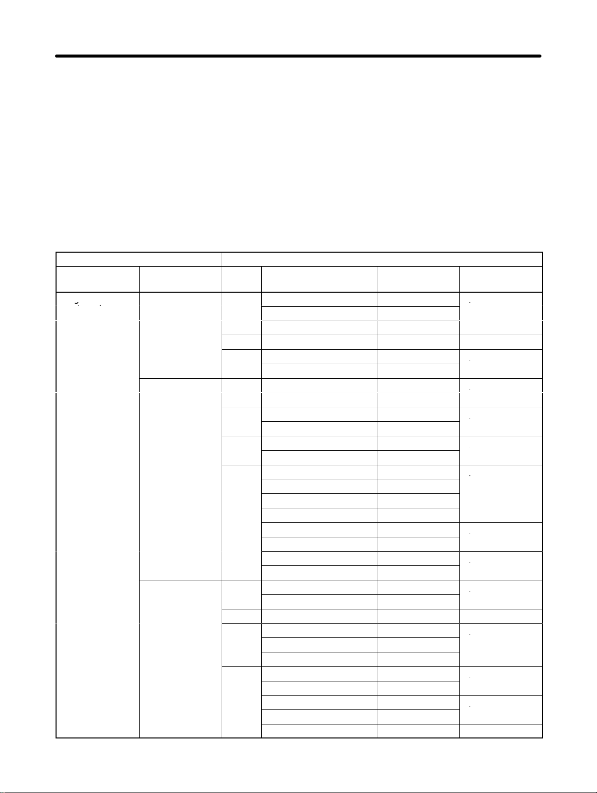
D Position Driver and AC Servomotor Combinations
Position
Input power
supply
Single-phase
200/240 (170 to
264) V
AC at
Driver
Model Series Model Output
FND-X06H-j U
U-UE R88M-UE10030j-S1 100 W 3,000 r/min
H
FND-X12H-j U
U-UE
H
M
FND-X25H-j U
U-UE R88M-UE75030j-S1 750 W 3,000 r/min
H
M
R88M-U03030jA 30 W
R88M-U05030jA 50 W
R88M-U10030jA 100 W
R88M-H05030 50 W
R88M-H10030 100 W
R88M-U20030jA 200 W
R88M-U40030jA 400 W
R88M-UE20030j-S1 200 W
R88M-UE40030j-S1 400 W
R88M-H20030 200 W
R88M-H30030 300 W
R88M-M06040 60 W
R88M-M12040 120 W
R88M-M20040 200 W
R88M-M40040 400 W
R88M-M20020 200 W
R88M-M40020 400 W
R88M-M20012 200 W
R88M-M40012 400 W
R88M-U75030jA 750 W
R88M-U1K030j 1000 W
R88M-H50030 500 W
R88M-H75030 750 W
R88M-H1K130 1100 W
R88M-M70040 700 W
R88M-M1K140 1100 W
R88M-M70020 700 W
R88M-M1K120 1100 W
R88M-M70012 700 W 1,200 r/min
Applicable AC Servomotor
-
Rated r/min
capacity
3,000 r/min
3,000 r/min
3,000 r/min
3,000 r/min
3,000 r/min
4,000 r/min
2,000 r/min
1,200 r/min
3,000 r/min
3,000 r/min
4,000 r/min
2,000 r/min
1-3
Page 19

50/60 Hz
g
,
50/60 Hz
,
,
Introduction Chapter 1
Position
Input power
supply
Three-phase
200/240 (170 to
264) V
AC at
Single-phase
100/115 (85 to
127) V
AC at
Driver
FND-X50H-j U
FND-X06L-j U
FND-X12L-j
Applicable AC Servomotor
ModelSeriesModel
capacity
R88M-U1K530j 1500 W
R88M-U2K030j 2000 W
M
U-UE R88M-UE10030j-S1 100 W 3,000 r/min
H
U R88M-U20030jA 200 W 3,000 r/min
U-UE R88M-UE20030j-S1 200 W 3,000 r/min
H R88M-H20030 200 W 3,000 r/min
M
R88M-M2K040 2000 W 4000 r/min
R88M-M1K820 1800 W
R88M-M2K220 2200 W
R88M-M1K112 1100 W
R88M-M1K412 1400 W
R88M-M1K812 1800 W
R88M-U03030jA 30 W
R88M-U05030jA 50 W
R88M-U10030jA 100 W
R88M-H05030 50 W
R88M-H10030 100 W
R88M-M06040 60 W
R88M-M12040 120 W
R88M-M20040 200 W
R88M-M20020 200 W 2,000 r/min
R88M-M20012 200 W 1,200 r/min
Rated r/minOutput
3000 r/min
2000 r/min
1200 r/min
3,000 r/min
3,000 r/min
4,000 r/min
Note 1. Even
when a U-series or U-UE-series
Position Driver
put
, a 200-V
Servomotor is used in combination with a100-V
AC Servomotor must be used. A 100-V
AC-in-
AC Servomotor cannot be
connected.
Note 2. Straight-axis servomotors are available either with or without a key or brake. In the above
table, the Servomotors have the following features.
U-series Straight axis without brake, without key
U-series UE models Straight axis without brake, with key (not available without key)
H-series Straight axis without brake, with key
M-series Straight axis without brake, with key (“A” cut for small-capacity)
Note 3. Motor control is enabled by setting the user parameter UP-02 of the Position Driver.
Note 4. U-series
UE-type and H-series Servomotors can
be used only with Position Driver software
version 4.01 (September 1997) or later.
U-series 1-kW to 2-kW Servomotors and M-series 1.1-kW to 2.2-kW Servomotors can be
used only with Position Driver software version 4.04 (April 1999) or later.
1-4
Page 20

Introduction Chapter 1
H Servomotor Features and Selection Standards
Any
FND-X-series Position Driver can be
selection, take the following points into consideration.
D Servomotor Features
U/UE Series
S Compact size, high-speed response
S High resolution (except for UE type)
S Absolute encoder system can be configured (except for UE type).
H Series
S High resolution
S High application load inertia (less than 10 times the rotary inertia)
S Usable in systems with comparatively low mechanical rigidity.
M Series
S High application load inertia (less than 10 times the rotary inertia)
freely selected according to the application. When making the
S Usable in systems with comparatively low mechanical rigidity.
S High output torque in a low-rotation motor
S Up to a maximum of 50 meters between Servomotor and Servo Driver.
D Motor Selection Standards (Reference)
Drive system type Low inertia High inertia
Ball screw direct connection U, U-UE, H, M U, U-UE, H, M
Turntable direct connection U, U-UE, H, M U, U-UE, H, M
Feeder (direct connection) U, U-UE, H, M U, U-UE, H, M
Harmonic drive U, U-UE, H, M H, M
Chain drive U, U-UE, H, M H, M
Belt drive U, U-UE, H, M H, M
Rack & pinion U, U-UE, H, M H, M
Note “Low
inertia” means that the motor axis conversion inertia is approximately 0 to 5 times the
inertia
for U-series and U-series UE-type Servomotors.
“High inertia” means that the motor axis conversion inertia is approximately 5 to 10 times the
rotary
inertia for U-series and U-series UE-type Servomotors.
for H-series and M-series Servomotors, and approximately 0 to
inertia for H-series and M-series Servomotors, and approximately 15 to 30 times the rotary
15 times the rotary inertia
rotary
H Position Control Functions
D Pulse Rate Setting Function
Pulse
rate setting makes it possible to set positioning data (i.e., positions and speeds) according to the
mechanical axis.
1-5
Page 21

Introduction Chapter 1
D Control Mode
The
following four types of control modes are available to the Position Driver: PTP
control
rect I/O signal input.
modes with the internal point data preset in the Position Driver and these same modes with di
D Internal Point Data
• A maximum of 64 points of data (Pd01j to Pd64j) can be set internally in the Position Driver.
• Positions can be set within a range between –39,999,999 to 39,999,999 with the absolute or incre-
mental value specified.
D Positioning Data Instruction by Direct Input
Eight-point
lowing ranges into the Position Driver.
Position Setting Range: –39,999,999 to 39,999,999 (with incremental or absolute setting)
Speed Setting Range: 1% to 100% (override setting with respect to reference speed)
input and input timing signals are used to
input position data and speed data within the fol
D Position Compensation Function
This
function executes
feeder control is used.
backlash compensation when PTP control is used, and slip compensation when
control and feeder
-
-
D Acceleration/Deceleration Function
•
Either linear (trapezoidal) acceleration or deceleration time or
celeration
and deceleration.
• The
ors smoothly or achieve feeder control with minimal feeder slippage.
or deceleration time can be selected. In addition,
S-shaped acceleration/deceleration function makes it possible, for example, to start up convey
S-shaped (primary low-pass filter) ac
dif
ferent times can be set for acceleration
D Stop Methods
• The stop method for when the STOP signal is turned OFF can be selected with PP-24.
Free-running stop: Motor power supply turned OFF.
Deceleration stop: Servo-lock
Error counter reset stop: Servo-lock
counter reset.
• The
stop method of the Position Driver in the case of overrun or software limit signal detection can be
selected with PP-25.
Overrun: Servo free-running stop with the alarm AL38 turned ON or servo-
lock stop.
Software limit detection: Servo-lock
after the operation decelerates to a stop in preset time.
after an immediate deceleration to a stop with the error
stop with or without alarms AL34 and AL35 turned ON.
-
-
H Teaching Functions
D Position Teaching
The
Position Driver has a teaching function that enables the Position Driver stop the mechanical axis
with
an external force
data automatically as part of PTP data.
1-6
by going into servo-free status or JOG operation and to take up the stop position
Page 22

Introduction Chapter 1
D Mechanical Origin Teaching
An
optional position can be specified as the mechanical origin by moving the position to the mechanical
origin and teaching after the completion of origin search.
H Motor Control Functions
D Motor Type and Capacity Selection by Motor Code
A motor type and capacity can be selected by setting UP-02 to the corresponding motor code.
D Auto-tuning Function
• The
Position
Driver,
turning
ity and characteristics of the machine load.
• The auto-tuning function makes it possible to save system startup time.
H Programming Devices
Driver has an auto-tuning function. If a machine and motor are connected to the Position
this function makes it possible
the motor and enables the automatic gain control of
to check the capacity and characteristics of the machine load by
the Position Driver according to the capac
-
D Teaching Box: CVM1-PRO01 + ROM Cassette
The Teaching Box provides for easy operation, including the following:
Position Driver status monitoring
Parameter editing and transfer
Teaching
Jogging
Positioning to specified points
Autotuning
Note Refer to the
CVM1-PRO01 Teaching Box Operation Manual (W354)
D OMNUC FND-X Series Monitoring Software
TheOMNUC
vides for easy operation, including the following:
Position Driver status monitoring
Parameter editing and transfer
Speed and current waveform displays
Autotuning
FND-X Series Monitoring Software runs on an IBM PC/A
T or compatible computer and
H Monitor Functions
for more information.
pro-
D Monitor Mode
The
motor speed, present value, reference value,
rent,
ef
fective load factor, electronic thermal value, electrical angle, and regenerative absorption rate
can be monitored on the front panel of the Position Driver in this mode.
position deviation value, machine speed, motor cur
D Check Mode
The
I/O
signal status, alarm details, alarm history
of the Position Driver in this mode.
, and software version are displayed on the front panel
-
1-7
Page 23

Introduction Chapter 1
H Protection and Self-diagnostic Functions
D Hardware Protection
The
Position Driver is protected from overcurrent,
ure, overcurrent (soft), speed amplifier saturation, and overload damage.
D Mechanical System Protection
The
mechanical system is protected from damage resulting
soft limit overflows, coordinate counter overflows, or overrun.
D Parameter Setting-related Errors
The Position Driver detects parameter setting errors.
D Detector-related Errors
Resolver
absolute
absolute encoder absolute failure, absolute encoder overspeed failure, encoder data failure, and encoder initialization failure.
wire burnout, resolver failure, encoder wire disconnection, encoder communications
encoder backup
failure, absolute encoder checksum failure, absolute encoder battery failure,
overvoltage, low voltage, abnormal power
from overspeed, error counter overflows,
, clock fail
failure,
-
D Position-related Errors
BCD data, indefinite PV, and PTP data non-setting errors.
H Test Functions
D Motor Test Function
The
Position Driver has a motor test function that makes it possible to easily check whether a motor is
connected
trolled with the operation keys and the motor speed can be set in UP-29. The motor speed is set to
50 r/min before shipping.
D Sequential Output Test Function
The
Position Driver has a sequential output test function that makes it possible
host controller is connected to the Position Driver. This function makes it possible to turn any output
terminal ON or OFF with the operation keys.
to the Position Driver
. When this function is enabled, the motor rotation direction can be con
to easily check whether a
-
1-8
Page 24
Introduction Chapter 1
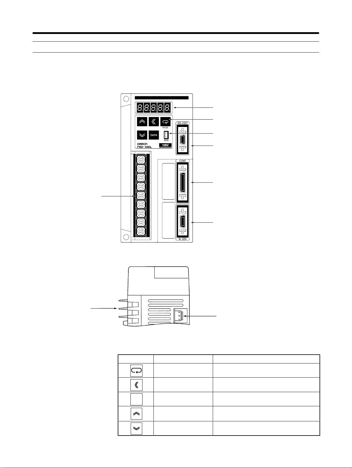
1-2 Nomenclature and Key Operations
D DIO Position Drivers
Front View
Display
(5-digit, 7-segment LEDs)
Operation Keys (5 keys)
Monitor Output Terminal
CN5 (RS-232C)
Communications
Connector
CN1 (CONT)
Control Signal
Terminal
Block
Connector
Bottom View
Radiation
fin
H Key Operations
CN2 (M.SEN)
Motor Sensor
Connector
CN6
BAT
Connector
Key Name Main function
Mode Key Changes the Position Driver’s mode.
Shift Key
Shifts the operation column to the left.
DATA
Data Key Saves the set data.
Increment Key Increments the parameter address or
data value.
Decrement Key Decrements the parameter address or
data value.
1-9
Page 25
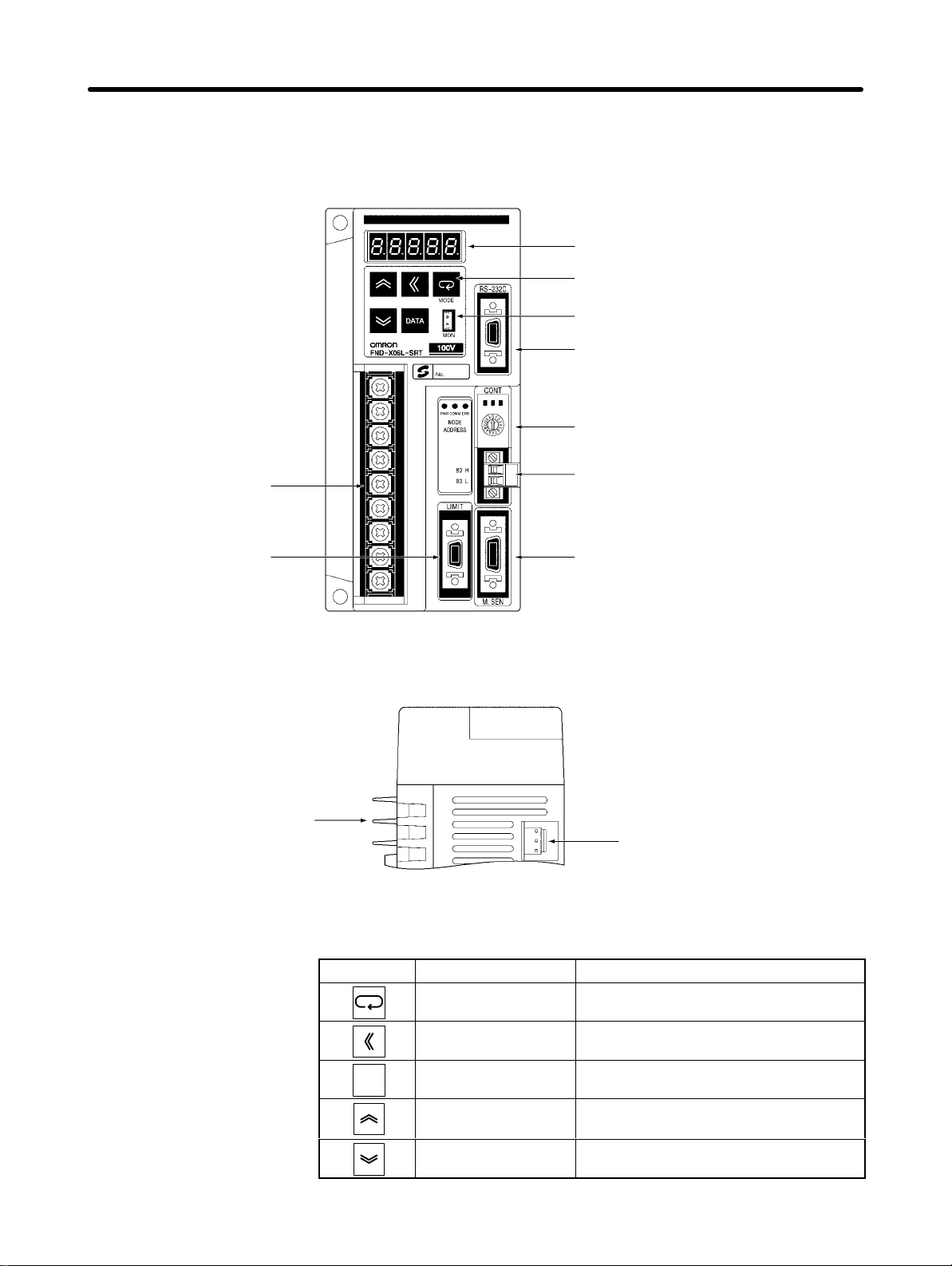
Introduction Chapter 1
D CompoBus/S Position Drivers
Front View
Display
(5-digit, 7-segment LEDs)
Operation Keys (5 keys)
Monitor Output Terminal
CN5 (RS-232C)
Communications
Connector
Node Address
Setting Switch
CN4 (LIMIT)
External control
signal connector
Bottom View
Terminal
Block
Radiation
CN1 (CONT)
Control Signal
Connector
CN2 (M.SEN)
Motor Sensor
Connector
fin
CN6
BAT Connector
H Key Operations
1-10
Key Name Main function
Mode Key Changes the Position Driver’s mode.
DATA
Shift Key
Data Key Saves the set data.
Shifts the operation column to the left.
Increment Key Increments the parameter address or
data value.
Decrement Key Decrements the parameter address or
data value.
Page 26
Introduction Chapter 1
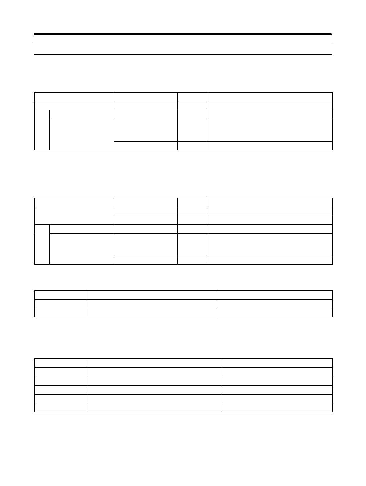
1-3 Supported Standards and Supporting Models
1-3-1 Standards Supported by Position Drivers
Standard Supported standard File No. Remarks
UL/cUL UL508C E179149 Electrical power conversion devices
EC
Low-voltage Directive EN50178 --- Industrial product specifications
EMC Directive
EN55011 class A
group 1
EN61000-4 --- Electromagnetic compatibility and immunity
--- Radio interference limits and measurement
methods for radio frequency devices for industrial, scientific, and medical applications
Note All Position Drivers in the FND-X Series conform to UL/cUL standards and EC directives.
1-3-2 Standards Supported by AC Servomotors
Standard Supported standard File No. Remarks
UL/cUL
EC
Low-voltage Directive IEC34-1, -5, -8, -9 --- Rotating electric devices
EMC Directive
UL1004 E179189 Electric motors
cUL C22.2 No. 100 E179189 Motors and generators
EN55011 class A
group 1
EN61000-4 --- Electromagnetic compatibility and immunity
--- Radio interference limits and measurement
methods for radio frequency devices for industrial, scientific, and medical applications
H Servomotors Conforming to UL/cUL Standards
Power supply AC Servomotors Encoder
200 VAC R88M-Ujjj30HA-j (30 to 750 W) Incremental encoder
200 VAC R88M-Ujjj30TA-j (30 to 750 W) Absolute encoder
Note Servomotors manufactured beginning in May 1998 conform to UL/cUL standards.
H Servomotors Conforming EC Directives
Power supply AC Servomotors Encoder
200 VAC R88M-Ujjj30VA-j (30 to 750 W) Incremental encoder
200 VAC R88M-Ujjj30XA-j (30 to 750 W) Absolute encoder
200 VAC R88M-UEjjj30V-j (100 to 750 W) Incremental encoder
200 VAC R88M-Ujjj30V-j (1 to 2 kW) Incremental encoder
200 VAC R88M-Ujjj30X-j (1 to 2 kW) Absolute encoder
Note The Servomotors must be wired as described in
2-2 Wiring
to conform to the EMC Directive.
1-11
Page 27
2
Chapter 2
Design and Installation
2-1 Installation
2-2 Wiring
Page 28
Design and Installation Chapter 2
2-1 Installation
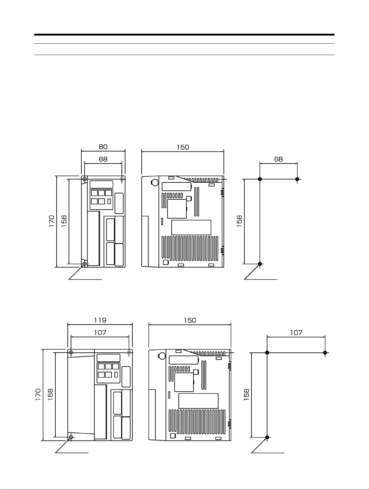
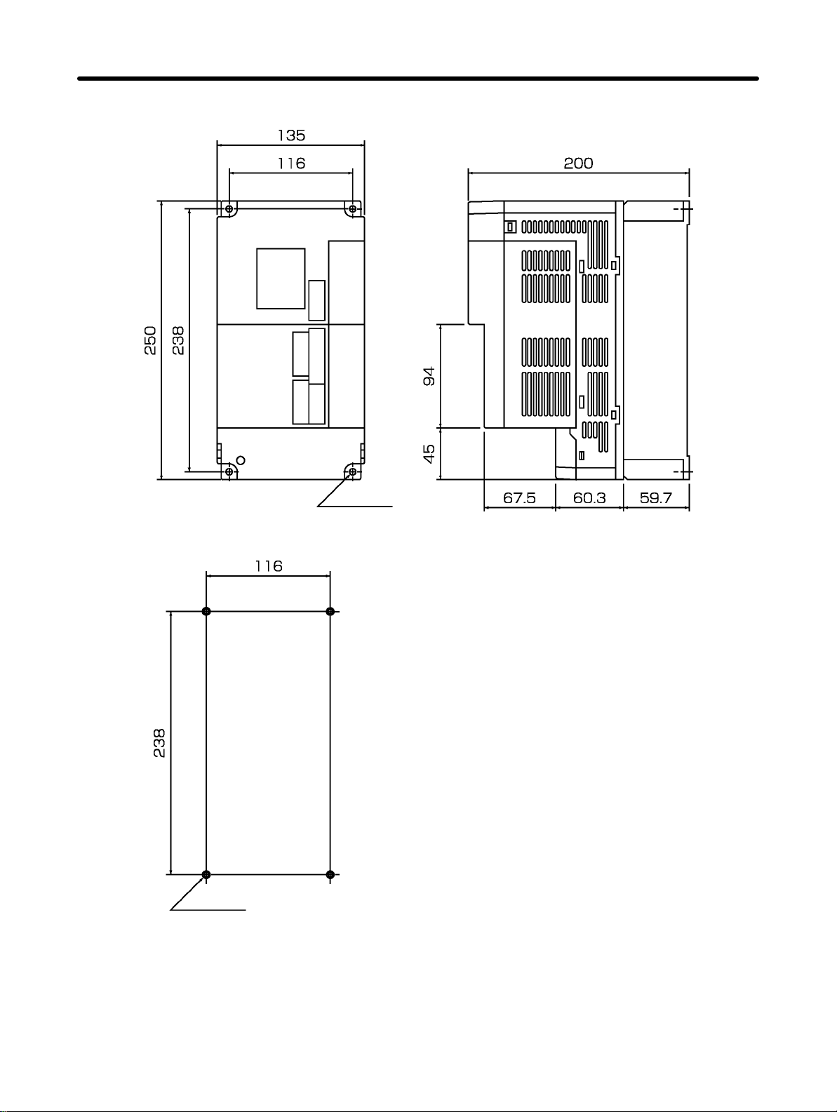
2-1-1 External Dimensions (Unit: mm)
H DIO and CompoBus/S Position Drivers
D 200-VAC FND-X06H-j/-X12H-j
100-VAC FND-X06L-j/-X12L-j
Mounting Dimensions
Three,
6 dia.
D 200-VAC FND-X25H-j
Three,
6 dia.
Three, M5
Mounting Dimensions
Three, M5
2-2
Page 29
Design and Installation Chapter 2
D 200-VAC FND-X50H-j
Mounting Dimensions
Four
, M5
Four,
6 dia.
2-3
Page 30
Design and Installation Chapter 2
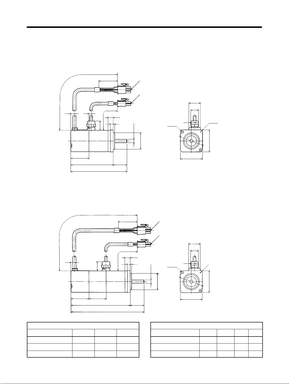
H OMNUC U-Series AC Servomotors with Incremental Encoders
(U-INC 30 to 750 W) Conforming to UL/cUL
D 30-W/50-W/100-W Standard Models (Without Brakes):
R88M-U03030HA, R88M-U05030HA, R88M-U10030HA
300±30
6.5 6
17
35
300±30
5
9.5
2.5
Encoder adapter
Motor plug
6h6 dia.
30h7 dia.
Two,
4.3 dia.
46
dia.
18
14
dia.
6
Four, R3.7
40
33
LL 25
L
D 30-W/50-W/100-W Models with Brakes:
R88M-U03030HA-B, R88M-U05030HA-B, R88M-U10030HA-B
300±30
6.5
35
300±30
9.5
2.55
17
33 LB
25LL
L
Encoder adapter
Motor plug
Two,
4.3 dia.
6h6 dia.
30h7 dia.
46
dia.
40
21
14
dia.
4
40
Four, R3.7
40
Standard Models (Without Brakes)
Model L LL S
R88M-U03030HA 94.5 69.5 6
R88M-U05030HA 102.0 77.0 6
R88M-U10030HA 119.5 94.5 8
2-4
Models with Brakes
Model L LL LB S
R88M-U03030HA-B 126 101 31.5 6
R88M-U05030HA-B 133.5 108.5 31.5 6
R88M-U10030HA-B 160 135 40.5 8
Page 31

Design and Installation Chapter 2
H OMNUC U-Series AC Servomotors with Incremental Encoders
(U-INC 30 to 750 W) Conforming to UL/cUL (Contd.)
D 200-W/400-W Standard Models (Without Brakes):
R88M-U20030HA, R88M-U40030HA
300±30
5.2 7
35
300±30
12
17
63
Encoder adapter
Motor plug
Four,
5.5 dia.
14h6 dia.
70
dia.
50h7 dia.
21
14
dia.
Four, R5.3
60
34
LL 30
L
D 200-W/400-W Models with Brakes:
R88M-U20030HA-B, R88M-U40030HA-B
5.2 5.5 7
17
300±30
35
300±30
12
63
60
Encoder adapter
Motor plug
14
Four,
5.5
dia.
14h6 dia.
70 dia.
50h7 dia.
21
dia.
Four, R5.3
60
34 39.5
LL 30
L
Standard Models (Without Brakes)
Model L LL
R88M-U20030HA 126.5 96.5
R88M-U40030HA 154.5 124.5
60
Models with Brakes
Model L LL
R88M-U20030HA-B 166 136
R88M-U40030HA-B 194 164
2-5
Page 32

Design and Installation Chapter 2
H OMNUC U-Series AC Servomotors with Incremental Encoders
(U-INC 30 to 750 W) Conforming to UL/cUL (Contd.)
D 750-W Standard Models (Without Brakes): R88M-U75030HA
300±30
35
85.2
17
300±30
15
83
Encoder adapter
Motor plug
Four,
7 dia.
21
14 dia.
Four, R8.2
16h6 dia.
35
34
145 40
185
D 750-W Models with Brakes: R88M-U75030HA-B
300±30
35
85.2
17
300±30
15
83
90 dia.
70h7 dia.
Encoder adapter
Motor plug
Four,
7 dia.
80
80
21
14 dia.
Four, R8.2
2-6
34 44.5
189.5 40
229.5
16h6 dia.
35
90 dia.
80
70h7 dia.
80
Page 33

Design and Installation Chapter 2
H OMNUC U-Series AC Servomotors with Incremental Encoders
(U-INC 30 to 750 W) Conforming to EC Directives
D 30-W/50-W/100-W Standard Models (Without Brakes):
R88M-U03030VA-S1, R88M-U05030VA-S1, R88M-U10030VA-S1
14 dia.
Two,
4.3 dia.
Sh6 dia.
46 dia.
30h7 dia.
D 30-W/50-W/100-W Models with Brakes:
R88M-U03030VA-BS1, R88M-U05030VA-BS1, R88M-U10030VA-BS1
14 dia.
Two,
4.3 dia.
Sh6 dia.
Four, R3.7
Four, R3.7
Standard Models (Without Brakes)
Model L LL S
R88M-U03030VA-S1 94.5 69.5 6
R88M-U05030VA-S1 102.0 77.0 6
R88M-U10030VA-S1 119.5 94.5 8
46 dia.
30h7 dia.
Models with Brakes
Model L LL LB S
R88M-U03030VA-BS1 126 101 31.5 6
R88M-U05030VA-BS1 133.5 108.5 31.5 6
R88M-U10030VA-BS1 160 135 40.5 8
2-7
Page 34

Design and Installation Chapter 2
H OMNUC U-Series AC Servomotors with Incremental Encoders
(U-INC 30 to 750 W) Conforming to EC Directives (Contd.)
D 200-W/400-W Standard Models (Without Brakes):
R88M-U20030VA-S1, R88M-U40030VA-S1
14 dia.
D 200-W/400-W Models with Brakes:
R88M-U20030VA-BS1, R88M-U40030VA-BS1
14h6 dia.
50h7 dia.
Four,
5.5 dia.
70 dia.
Four, R5.3
14 dia.
Standard Models (Without Brakes)
Model L LL
R88M-U20030VA-S1 126.5 96.5
R88M-U40030VA-S1 154.5 124.5
2-8
Four,
14h6 dia.
50h7 dia.
5.5 dia.
70 dia.
Four, R5.3
Models with Brakes
Model L LL
R88M-U20030VA-BS1 166 136
R88M-U40030VA-BS1 194 164
Page 35

Design and Installation Chapter 2
H OMNUC U-Series AC Servomotors with Incremental Encoders
(U-INC 30 to 750 W) Conforming to EC Directives (Contd.)
D 750-W Standard Models (Without Brakes): R88M-U75030VA-S1
14 dia.
Four,
16h6 dia.
70h7 dia.
D 750-W Models with Brakes: R88M-U75030VA-BS1
7 dia.
90 dia.
Four, R8.2
Four,
16h6 dia.
70h7 dia.
14 dia.
Four, R8.2
7 dia.
90 dia.
2-9
Page 36

Design and Installation Chapter 2
H OMNUC U-Series AC Servomotors with Absolute Encoders
(U-ABS 30 to 750 W) Conforming to UL/cUL
D 30-W/50-W/100-W Standard Models (Without Brakes):
R88M-U03030TA, R88M-U05030TA, R88M-U10030TA
Encoder adapter
Motor plug
14 dia.
Four
, R3.7
53
dia.
Sh6 dia.
30h7 dia.
Two,
4.3 dia.
46 dia.
D 30-W/50-W/100-W Models with Brakes:
R88M-U03030TA-B, R88M-U05030TA-B, R88M-U10030TA-B
Encoder adapter
Motor plug
53
dia.
Standard Models (Without Brakes)
Model L LL S
R88M-U03030TA 117.5 92.5 6
R88M-U05030TA 125 100 6
R88M-U10030TA 142.5 117.5 8
Sh6 dia.
30h7 dia.
R88M-U03030TA-B 149 124 31.5 6
R88M-U05030TA-B 156.5 131.5 31.5 6
R88M-U10030TA-B 183 158 40.5 8
Two,
Model L LL LB S
14
dia.
4.3 dia.
46 dia.
Models with Brakes
Four
, R3.7
2-10
Page 37

Design and Installation Chapter 2
H OMNUC U-Series AC Servomotors with Absolute Encoders
(U-ABS 30 to 750 W) Conforming to UL/cUL (Contd.)
D 200-W/400-W Standard Models (Without Brakes):
R88M-U20030TA, R88M-U40030TA
Encoder adapter
Motor plug
14
dia.
D 200-W/400-W Models with Brakes:
R88M-U20030TA-B, R88M-U40030TA-B
14h6 dia.
14h6 dia.
Four
, 5.5.dia.
70 dia.
50h7 dia.
Encoder adapter
Motor plug
Four
, 5.5.dia.
Four,
R5.3
14
dia.
Four,
R5.3
Standard Models (Without Brakes)
Model L LL
R88M-U20030TA 147.5 117.5
R88M-U40030TA 175.5 145.5
70 dia.
50h7 dia.
Models with Brakes
Model L LL
R88M-U20030TA-B 187 157
R88M-U40030TA-B 215 185
2-11
Page 38

Design and Installation Chapter 2
H OMNUC U-Series AC Servomotors with Absolute Encoders
(U-ABS 30 to 750 W) Conforming to UL/cUL (Contd.)
D 750-W Standard Models (Without Brakes): R88M-U75030TA
Encoder adapter
Motor plug
14
dia.
Four,
Four
, 7 dia.
R8.2
16h6 dia.
D 750-W Models with Brakes: R88M-U75030TA-B
90 dia.
70h7 dia.
Encoder adapter
Motor plug
Four
, 7 dia.
14
dia.
Four,
R8.2
2-12
16h6 dia.
90 dia.
70h7 dia.
Page 39

Design and Installation Chapter 2
H OMNUC U-Series AC Servomotors with Absolute Encoders
(U-ABS 30 to 750 W) Conforming to EC Directives
D 30-W/50-W/100-W Standard Models (Without Brakes):
R88M-U03030XA-S1, R88M-U05030XA-S1, R88M-U10030XA-S1
14 dia.
Two,
4.3 dia.
53 dia.
Sh6 dia.
30h7 dia.
46 dia.
D 30-W/50-W/100-W Models with Brakes:
R88M-U03030XA-BS1, R88M-U05030XA-BS1, R88M-U10030XA-BS1
Two,
4.3 dia.
Sh6 dia.
46 dia.
53
dia.
30h7 dia.
Four, R3.7
14 dia.
Four, R3.7
Standard Models (Without Brakes)
Model L LL S
R88M-U03030XA-S1 117.5 92.5 6
R88M-U05030XA-S1 125 100 6
R88M-U10030XA-S1 142.5 117.5 8
Models with Brakes
Model L LL LB S
R88M-U03030XA-BS1 149 124 31.5 6
R88M-U05030XA-BS1 156.5 131.5 31.5 6
R88M-U10030XA-BS1 183 158 40.5 8
2-13
Page 40

Design and Installation Chapter 2
H OMNUC U-Series AC Servomotors with Absolute Encoders
(U-ABS 30 to 750 W) Conforming to EC Directives (Contd.)
D 200-W/400-W Standard Models (Without Brakes):
R88M-U20030XA-S1, R88M-U40030XA-S1
14 dia.
Four,
5.5 dia.
14h6 dia.
70 dia.
50h7 dia.
Four, R5.3
D 200-W/400-W Models with Brakes:
R88M-U20030XA-BS1, R88M-U40030XA-BS1
14h6 dia.
50h7 dia.
Four,
70 dia.
5.5 dia.
14 dia.
Four, R5.3
Standard Models (Without Brakes)
Model L LL
R88M-U20030XA-S1 147.5 117.5
R88M-U40030XA-S1 175.5 145.5
2-14
Models with Brakes
Model L LL
R88M-U20030XA-BS1 187 157
R88M-U40030XA-BS1 215 185
Page 41
Design and Installation Chapter 2
H OMNUC U-Series AC Servomotors with Absolute Encoders
(U-ABS, 30 to 750 W) Conforming to EC Directives (Contd.)
D 750-W Standard Models (Without Brakes): R88M-U75030XA-S1
14 dia.
16h6 dia.
D 750-W Models with Brakes: R88M-U75030XA-BS1
Four,
90 dia.
70h7 dia.
7 dia.
Four, R8.2
Four,
16h6 dia.
14 dia.
Four, R8.2
7 dia.
90 dia.
70h7 dia.
2-15
Page 42

Design and Installation Chapter 2
H U-Series AC Servomotor Shaft Dimensions with Keys
(U-INC, U-ABS, 30 to 750 W)
Standard U-series AC Servomotors do not have keys on the shafts. The shaft dimensions of motors
keys are shown below
with
ber. Key slots are based on JIS B1301-1976.
D 30-W/50-W Models
Standard: R88M-U03030j-S1, R88M-U05030j-S1
With Brakes: R88M-U03030j-BS1, R88M-U05030j-BS1
D 100-W Models
Standard: R88M-U10030j-S1
With Brakes: R88M-U10030j-BS1
. Motors with keys are indicated by adding “-S1” to the end of
14
14
Dia.:
Dia.:
6h6
8h6
2
1.2
2
1.8
3
the model num
-
3
D 200-W/400-W Models
Standard: R88M-U20030j-S1, R88M-U40030j-S1
With Brakes: R88M-U20030j-BS1, R88M-U40030j-BS1
20
Dia.:
14h6
5
5
D 750-W Models
Standard: R88M-U75030j-S1
With Brakes: R88M-U75030j-BS1
30
Dia.:
16h6
5
5
3
3
2-16
Page 43

Design and Installation Chapter 2
H OMNUC U-UE-Series AC Servomotors with Incremental Encoders (UE)
Not Conforming to Any Standards
D 100-W Standard Models (Without Brakes): R88M-UE10030H-S1
Encoder adapter
Motor plug
Shaft end dimensions
Key slot dimensions, conform to JIS B1301-1976.
Two, 4.3 dia.
8h6 dia.
46 dia.
30h7 dia.
Four, R3.7
8h6 dia.
D 100-W Models with Brakes: R88M-UE10030H-BS1
Encoder adapter
Motor plug
Two, 4.3 dia.
8h6 dia.
46 dia.
30h7 dia.
Shaft end dimensions
Key slot dimensions, conform to JIS B1301-1976.
Four, R3.7
8h6 dia.
2-17
Page 44

Design and Installation Chapter 2
H OMNUC U-UE-Series AC Servomotors with Incremental Encoders (UE)
(Contd.)
D 200-W/400-W Standard Models (Without Brakes):
R88M-UE20030H-S1, R88M-UE40030H-S1
Encoder adapter
Motor plug
Shaft end dimensions
Key slot dimensions, conform to JIS B1301-1976.
Four, 5.5 dia.
14h6 dia.
70 dia.
50h7 dia.
Four, R5.3
14h6 dia.
D 200-W/400-W Models with Brakes:
R88M-UE20030H-BS1, R88M-UE40030H-BS1
Standard Models (Without Brakes)
Model L LL
R88M-UE20030H-S1 126.5 96.5
R88M-UE40030H-S1 154.5 124.5
Encoder adapter
Motor plug
Shaft end dimensions
Key slot dimensions, conform to JIS B1301-1976.
Four, 5.5 dia. Four, R5.3
14h6 dia.
70 dia.
50h7 dia.
Models with Brakes
Model L LL
R88M-UE20030H-BS1 166 136
R88M-UE40030H-BS1 194 164
14h6 dia.
2-18
Page 45

Design and Installation Chapter 2
H OMNUC U-UE-Series AC Servomotors with Incremental Encoders (UE)
Not Conforming to Any Standards (Contd.)
D 750-W Standard Models (Without Brakes): R88M-UE75030H-S1
Encoder adapter
Motor plug
Four, 7 dia.
90 dia.
16h6 dia.
70h7 dia.
D 750-W Models with Brakes: R88M-UE75030H-BS1
Encoder adapter
Motor plug
Four, 7 dia.
Four, R8.2
16h6 dia.
Shaft end dimensions
Key slot dimensions, conform to JIS B1301-1976.
Four, R8.2
90 dia.
16h6 dia.
70h7 dia.
16h6 dia.
Shaft end dimensions
Key slot dimensions, conform to
JIS B1301-1976.
2-19
Page 46

Design and Installation Chapter 2
H OMNUC U-UE-Series AC Servomotors with Incremental Encoders (UE)
Conforming to EC Directives
D 100-W Standard Models (Without Brakes): R88M-UE10030V-S1
14 dia.
Shaft end dimensions
Key slot dimensions, conform to JIS B1301-1976.
8h6 dia.
8h6 dia.
30h7 dia.
Two, 4.3 dia.
46 dia.
Four, R3.7
D 100-W Models with Brakes: R88M-UE10030V-BS1
Two, 4.3 dia.
8h6 dia.
46 dia.
30h7 dia.
Shaft end dimensions
Key slot dimensions, conform to JIS B1301-1976.
8h6 dia.
14 dia.
Four, R3.7
2-20
Page 47

Design and Installation Chapter 2
H OMNUC U-UE-Series AC Servomotors with Incremental Encoders (UE)
Conforming to EC Directives (Contd.)
D 200-W/400-W Standard Models (Without Brakes):
R88M-UE20030V-S1, R88M-UE40030V-S1
Shaft end dimensions
Key slot dimensions, conform to JIS B1301-1976.
14h6 dia.
14 dia.
14h6 dia.
50h7 dia.
D 200-W/400-W Models with Brakes:
R88M-UE20030V-BS1, R88M-UE40030V-BS1
Four, 5.5 dia.
70 dia.
14 dia.
Four, R5.3
Shaft end dimensions
Key slot dimensions, conform to
JIS B1301-1976.
14h6 dia.
Standard Models (Without Brakes)
Model L LL
R88M-UE20030V-S1 126.5 96.5
R88M-UE40030V-S1 154.5 124.5
Four, 5.5 dia.
14h6 dia.
70 dia.
50h7 dia.
Four, R5.3
Models with Brakes
Model L LL
R88M-UE20030V-BS1 166 136
R88M-UE40030V-BS1 194 164
2-21
Page 48

Design and Installation Chapter 2
H OMNUC U-UE-Series AC Servomotors with Incremental Encoders (UE)
Conforming to EC Directives (Contd.)
D 750-W Standard Models (Without Brakes): R88M-UE75030V-S1
Shaft end dimensions
Key slot dimensions, conform to JIS B1301-1976.
14 dia.
Four, 7 dia.
16h6 dia.
90 dia.
70h7 dia.
16h6 dia.
Four, R8.2
D 750-W Models with Brakes: R88M-UE75030V-BS1
16h6 dia.
Four, 7 dia.
70h7 dia.
Shaft end dimensions
Key slot dimensions, conform to JIS B1301-1976.
16h6 dia.
14 dia.
Four, R8.2
90 dia.
2-22
Page 49

Design and Installation Chapter 2
H OMNUC U-Series AC Servomotors with Incremental Encoders (U-INC
1 to 2 kW)
D 1.0-kW/1.5-kW/2.0-kW Standard Models (Without Brakes)
Not Conforming to Any Standards: R88M-U1K030H/-U1K530H/-U2K030H
Conforming to EC Directives: R88M-U1K030V-S1/-U1K530V-S1/-U2K030V-S1
24h6 dia.
95h7 dia.
130 dia.
115 dia.
Four, 7 dia.
D 1.0-kW/1.5-kW/2.0-kW Models With Brakes
Not Conforming to Any Standards: R88M-U1K030H-B/-U1K530H-B/-U2K030H-B
Conforming to EC Directives: R88M-U1K030V-BS1/-U1K530V-BS1/-U2K030V-BS1
24h6 dia.
95h7 dia.
130 dia.
115 dia.
Four, 7 dia.
Standard Models (Without Brakes)
Model L LL
R88M-U1K030j 194 149
R88M-U1K530j 220 175
R88M-U2K030j 243 198
R88M-U1K030j-Bj 238 193
R88M-U1K530j-Bj 264 219
R88M-U2K030j-Bj 287 242
Models with Brakes
Model L LL
Note Servomotors with model numbers ending in “S1” have straight shafts with keys. Refer to
2-25 U-Series AC Servomotor Shaft Dimensions with Keys
for key dimensions.
page
2-23
Page 50

Design and Installation Chapter 2
H OMNUC U-Series AC Servomotors with Absolute Encoders (U-ABS
1 to 2 kW)
D 1.0-kW/1.5-kW/2.0-kW Standard Models (Without Brakes)
Not Conforming to Any Standards: R88M-U1K030T/-U1K530T/-U2K030T
Conforming to EC Directives: R88M-U1K030X-S1/-U1K530X-S1/-U2K030X-S1
24h6 dia.
95h7 dia.
130 dia.
115 dia.
Four, 7 dia.
D 1.0-kW/1.5-kW/2.0-kW Models With Brakes
Not Conforming to Any Standards: R88M-U1K030T-B/-U1K530T-B/-U2K030T-B
Conforming to EC Directives: R88M-U1K030X-BS1/-U1K530X-BS1/-U2K030X-BS1
24h6 dia.
95h7 dia.
130 dia.
115 dia.
Four, 7 dia.
Standard Models (Without Brakes)
Model L LL
R88M-U1K030j 208 163
R88M-U1K530j 234 189
R88M-U2K030j 257 212
R88M-U1K030j-Bj 252 207
R88M-U1K530j-Bj 278 233
R88M-U2K030j-Bj 301 256
Models with Brakes
Model L LL
Note Servomotors with model numbers ending in “S1” have straight shafts with keys. Refer to
2-25 U-Series AC Servomotor Shaft Dimensions with Keys
for key dimensions.
2-24
page
Page 51

Design and Installation Chapter 2
H U-Series AC Servomotor Shaft Dimensions with Keys
(U-INC, U-ABS, 1 to 2 kW)
Standard U-series AC Servomotors do not have keys on the shafts. The shaft dimensions of motors
keys are shown below
with
ber. Key slots are based on JIS B1301-1976.
D 1.0-kW/1.5-kW/2.0-kW Models
Standard: R88M-U1K030j-S1, R88M-U1K530j-S1, R88M-U2K030j-S1
With Brakes: R88M-U1K030j-BS1, R88M-U1K530j-BS1, R88M-U2K030j-BS1
. Motors with keys are indicated by adding “-S1” to the end of
24h6 dia.
M8 with effective
depth of 16
the model num
-
2-25
Page 52

Design and Installation Chapter 2
H OMNUC H-Series AC Servomotor with Incremental Encoder (H)
D 50-W/100-W Standard Models (Without Brakes): R88M-H05030, R88M-H10030
D 50-W/100-W Models with Brakes: R88M-H05030-B, R88M-H10030-B
Four, R4
93 dia. max.
63 dia.
50
0
ć0.025
Ădia.
80±0.2 dia.
Four, 5 dia.
Standard Models (Without Brakes)
Model L1 L2 L3
R88M-H05030 (50 W) 53.5 99 45.5
R88M-H10030 (100 W) 63.5 109 45.5
66 66±0.4
Models With Brakes
Model L1 L2 L3
R88M-H05030-B (50 W) 84.5 130 45.5
R88M-H10030-B (100 W) 94.5 140 45.5
8
ć0.009
0
Ădia.
D 200-W/300-W Standard Models (Without Brakes): R88M-H20030, R88M-H30030
D 200-W/300-W Models with Brakes: R88M-H20030-B, R88M-H30030-B
Four, R10
0
14
Ădia.
ć0.011
77 dia.
107 dia. max.
0
70
Ădia.
ć0.03
90±0.2 dia.
Four, 6 dia.
Standard Models (Without Brakes)
Model L1 L2 L3
R88M-H20030 (200 W) 77 123.5 46.5
R88M-H30030 (300 W) 89 135.5 46.5
2-26
80 80±0.4
Models With Brakes
Model L1 L2 L3
R88M-H20030-B (200 W) 107.5 154 46.5
R88M-H30030-B (300 W) 119.5 166 46.5
Page 53

Design and Installation Chapter 2
H OMNUC H-Series AC Servomotors with Incremental Encoders (H)
(Contd.)
D 500-W/750-W/1100-W Standard Models (Without Brakes):
R88M-H50030, R88M-H75030, R88M-H1K130
D 500-W/750-W/1100-W Models with Brakes:
R88M-H50030-B, R88M-H75030-B, R88M-H1K130-B
Four, R15
162 dia. max.
77 dia.
Shaft
Dimensions
R88M-H50030/-H50030-B
R88M-H75030/-H75030-B
0
16
Ădia.
ć0.011
Shaft Dimensions
R88M-H1K130/-H1K130-B
0
19
Ădia.
ć0.013
110
0
ć0.035
Ădia.
130±0.2 dia.
Four, 9 dia.
Standard Models (Without Brakes)
Model L1 L2 L3
R88M-H50030 (500 W) 107.5 154.0 46.5
R88M-H75030 (750 W) 126.0 172.5 46.5
R88M-H1K130 (1100 W) 144.5 191.0 46.5
Models With Brakes
Model L1 L2 L3
R88M-H50030-B (500 W) 148.5 195.0 46.5
R88M-H75030-B (750 W) 167.0 213.5 46.5
R88M-H1K130-B (1100 W) 185.5 232.0 46.5
2-27
Page 54

Design and Installation Chapter 2
H OMNUC M-Series AC Servomotors with Resolvers (M)
D 60-W/120-W (4,000 r/min) Standard Models (Without Brakes): R88M-M06040,
R88M-M12040
7.4 dia.
8h6 dia.
50h7 dia.
…
Four,
5 dia.
D 60-W/120-W (4,000 r/min) Models with Brakes: R88M-M06040-B, R88M-M12040-B
7.4 dia.
8h6 dia.
50h7 dia.
°
°
Four,
5 dia.
Standard Models (Without Brakes)
Model L LL LM
R88M-M06040 150 120 85
R88M-M12040 175 145 110
D Shaft End Dimensions
2-28
Models with Brakes
Model LX LY LM
R88M-M06040-B 184 154 85
R88M-M12040-B 209 179 110
Page 55

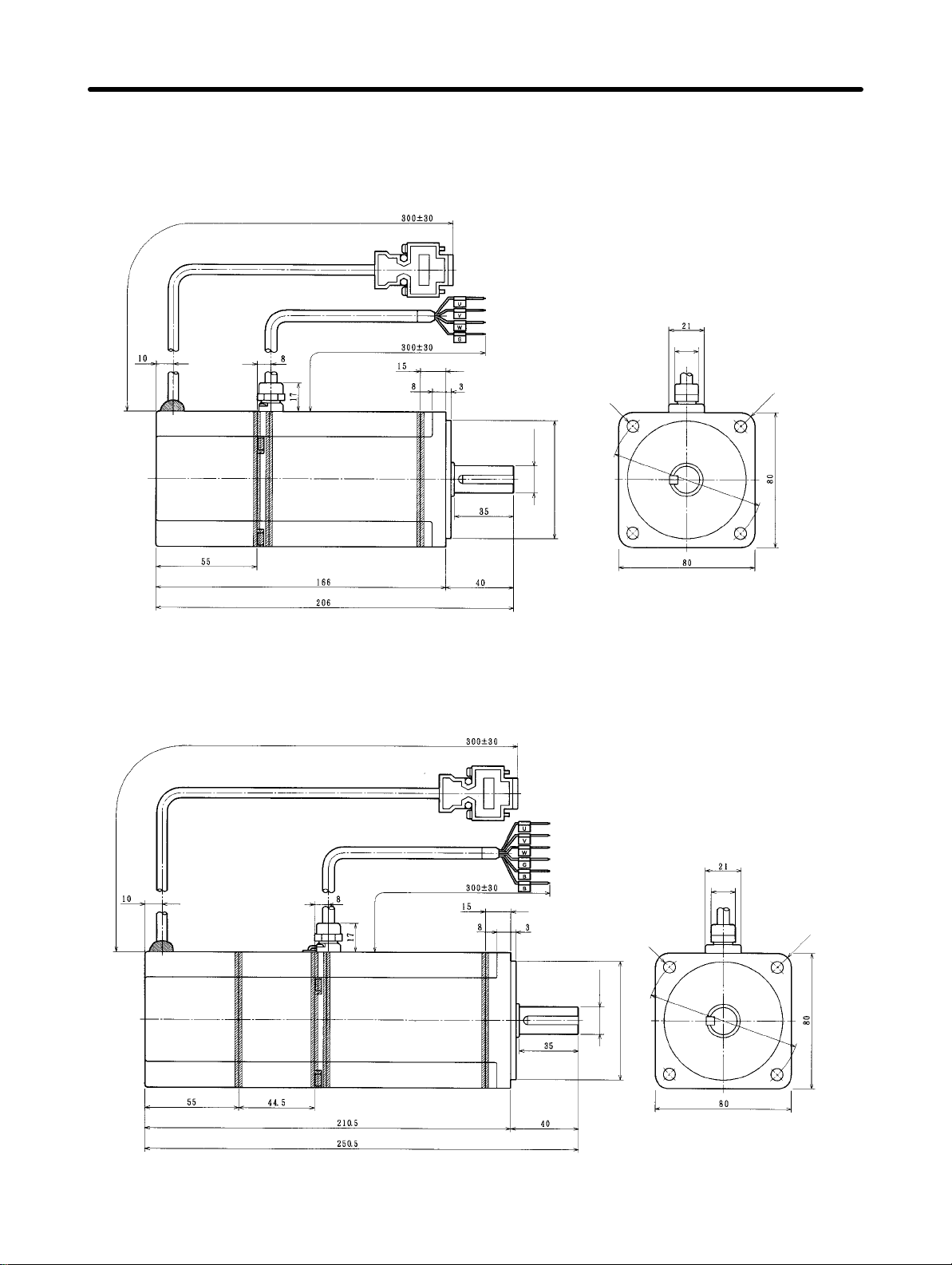
Design and Installation Chapter 2
H OMNUC M-Series AC Servomotors with Resolvers (M) (Contd.)
D 200-W (2,000 r/min) Standard Models (Without Brakes): R88M-M20020
D 200-W/400-W (4,000 r/min) Standard Models: R88M-M20040, R88M-40040
7.4 dia.
14h6 dia.
100±0.2 dia
80h7 dia.
Four, 7dia.
D 200-W (2,000 r/min) Models with Brakes: R88M-M20020-B
D 200-W/400-W (4,000 r/min) Models with Brakes: R88M-M20040-B, R88M-M40040-B
7.4 dia.
14h6 dia.
80h7 dia.
100±0.2 dia
Four, 7dia.
Standard Models (Without Brakes)
Model L LL LM
R88M-M20040 166 131 92
R88M-M20020
196 161 122
R88M-M40040
Model LX LY LM
R88M-M20040-B 196 161 92
R88M-M20020-B
R88M-M40040-B
Models with Brakes
226 191 122
D Shaft End Dimensions
2-29
Page 56

Design and Installation Chapter 2
H OMNUC M-Series AC Servomotors with Resolvers (M) (Contd.)
D 200-W/400-W/700-W (1,200 r/min)
Standard Models (Without Brakes): R88M-M20012, R88M-M40012, R88M-M70012
D 400-W/700-W/1,100-W (2,000 r/min) Standard Models (Without Brakes):
R88M-M40020, R88M-M70020, R88M-M1K120
D 700-W/1,100-W/2,000-W (4,000 r/min) Standard Models (Without Brakes):
R88M-70040, R88M-M1K140, R88M-M2K040
19h6 dia.
145±0.2 dia.
10h7 dia.
1
Four, 9 dia.
D 200-W/400-W/700-W (1,200 r/min)
Models with Brakes: R88M-M20012-B, R88M-M40012-B, R88M-M70012-B
D 400-W/700-W/1,100-W (2,000 r/min) Models with Brakes: R88M-M40020-B,
R88M-M70020-B, R88M-M1K120B
D 700-W/1,100-W/2,000-W (4,000 r/min) Models with Brakes: R88M-M70040-B,
R88M-M1K140-B, R88M-M2K040-B
2-30
19h6 dia.
145±0.2 dia.
10h7 dia.
1
165
dia.
Four, 9 dia.
Page 57

Design and Installation Chapter 2
Standard Models
Model L LL LM
R88M-M20012
240 195 156
R88M-M40020
R88M-M70040
R88M-M40012
275 230 191
R88M-M70020
R88M-M1K140
R88M-M70012
345 300 261
R88M-M1K120
R88M-M2K040
D Shaft End Directions
Models with Brakes
Model LX LY LM
R88M-M20012-B
282 237 156
R88M-M40020-B
R88M-M70040-B
R88M-M40012-B
317 272 191
R88M-M70020-B
R88M-M1K140-B
R88M-M70012-B
387 342 261
R88M-M1K120-B
R88M-M2K040-B
H OMNUC M-Series AC Servomotors with Resolvers (Contd.)
D 1,100-W/1,400-W/1,800-W (1,200 r/min) Standard Models:
R88M-M1K112/-M1K412/-M1K812
D 1,800-W/2,200-W (2,000 r/min) Standard Models:
R88M-M1K820/-M2K220
0
+0.01
35 dia.
114.3h7
200±0.3 dia.
180 x 180
230
Four, 14 dia.
dia.
2-31
Page 58

Design and Installation Chapter 2
D 1,100-W/1,400-W/1,800-W (1,200 r/min) Models with Brakes:
R88M-M1K112-B/-M1K412-B/-M1K812-B
D 1,800-W/2,200-W (2,000 r/min) Models with Brakes:
R88M-M1K820-B/-M2K220-B
0
+0.01
35 dia.
114.3h7
200±0.3 dia.
180 x 180
Standard Models
Model L LL LM LX LY LZ
R88M-M1K112
370 291 252 439 360 256
R88M-M1K820
R88M-M1K412
400 321 282 469 390 286
R88M-M2K220
R88M-M1K812 460 381 342 529 450 346
D Shaft End Directions
R5
230
dia.
Four, 14 dia.
Models with Brakes
Model L LL LM LX LY LZ
R88M-M1K112-B
R88M-M1K820-B
R88M-M1K412-B
R88M-M2K220-B
R88M-M1K812-B 460 381 342 529 450 346
4.5
C1
h9
10
60
8
370 291 252 439 360 256
400 321 282 469 390 286
2-32
Page 59

É
É
É
É
É
É
É
É
É
É
É
Design and Installation Chapter 2
2-1-2 Installation Conditions
H Position Driver
D Space Around Drivers
• Install
• Mount the Position Drivers vertically (so that the model number and writing can be read).
Position Drivers according to the dimensions shown in the following illustration
er
heat dispersion and convection inside the panel. Also install a fan
for circulation if Position Drivers
to ensure prop
are installed side by side to prevent uneven temperatures from developing inside the panel.
ЙЙЙЙЙЙЙЙЙЙЙЙЙЙЙЙЙЙЙЙ
50
ЙЙЙЙЙЙЙЙЙЙЙЙЙЙЙЙЙЙЙЙ
ЙЙЙЙЙЙЙЙЙЙЙЙЙЙЙЙЙЙЙЙ
ЙЙЙЙЙЙЙЙЙЙЙЙЙЙЙЙЙЙЙЙ
ЙЙЙЙЙЙЙЙЙЙЙЙЙЙЙЙЙЙЙЙ
ЙЙЙЙЙЙЙЙЙЙЙЙЙЙЙЙЙЙЙЙ
ЙЙЙЙЙЙЙЙЙЙЙЙЙЙЙЙЙЙЙЙ
ЙЙЙЙЙЙЙЙЙЙЙЙЙЙЙЙЙЙЙЙ
ЙЙЙЙЙЙЙЙЙЙЙЙЙЙЙЙЙЙЙЙ
ЙЙЙЙЙЙЙЙЙЙЙЙЙЙЙЙЙЙЙЙ
30 mm min.
ЙЙЙЙЙЙЙЙЙЙЙЙЙЙЙЙЙЙЙЙ
Fan Fan
Position Driver
Position Driver
W
W = 10 mm min.
Position Driver
W
mm min.
Side of Driver
50 mm min.
-
D Operating Environment
Be sure that the environment in which Position Drivers are operated meets the following conditions.
• Ambient operating temperature: 0°C to +55°C
• Ambient operating humidity: 35% to 90% (RH, with no condensation)
• Atmosphere: No corrosive gases.
D Ambient Temperature
• Position
maintain a high level of reliability.
• Temperature
the
vent the ambient temperature of the Position Driver from exceeding 55°C.
• Position
Use
heat.
• The
trolytic
ume
due
mum ambient temperature of 35°C, then a service life of approximately 50,000 hours can be expected.
life.
Drivers should be
operated in environments in which there is minimal temperature rise to
rise in any Position Driver installed in a closed space, such as a control box, will cause
ambient temperature to rise inside the entire closed space. Use a fan or a air conditioner to pre
Driver surface temperatures may rise to as much as 40°C above the ambient temperature.
heat-resistant materials for wiring,
service life of
a Position Driver is largely determined by the temperature around the internal elec
capacitors. The service life of an electrolytic capacitor is af
and an increase in internal resistance, which can result in overvoltage alarms, malfunctioning
to noise, and damage to individual elements. If a Position Driver is always operated at the maxi
A drop of 10°C in the ambient temperature will approximately double the expected service
and keep separate any devices or wiring that are sensitive to
fected by a drop in electrolytic vol
2-33
-
-
-
-
Page 60

Design and Installation Chapter 2
D Keeping Foreign Objects Out of Units
• Place
• Take
H AC Servomotors
D Operating Environment
Be sure that the environment in which the Servomotor is operated meets the following conditions.
• Ambient operating temperature: 0°C to +40°C
• Ambient operating humidity: OMNUC U Series: 20% to 80% (RH, with no condensation)
• Atmosphere: No corrosive gases.
D Impact and Load
• The Servomotor is resistant to impacts of up to
• Always use a pulley remover to remove pulleys,
• Secure cables so that there is no impact or load placed on the cable connector areas.
a cover over the Units or take other preventative measures to prevent foreign objects, such as
drill
filings, from getting into the Position Driver during installation.
installation is complete. If the
measures during installation and operation to
cover
is left on during operation, heat buildup may damage the Driver
prevent foreign objects such as metal particles,
Be sure to remove the cover after
oil, machining oil, dust, or water from getting inside of the Position Driver.
OMNUC U-UE Series: 20% to 80% (RH, with no condensation)
OMNUC H Series: 35% to 85% (RH, with no condensation)
OMNUC M Series: 35% to 85% (RH, with no condensation)
98 m/s
loads
2
{10 G}. Do not subject it to
during transport, installation,
heavy impacts or
or positioning. In
addition, do not hold onto the encoder/resolver
area,
cable, or connector areas when transporting it.
couplings, or other objects from the shaft.
.
D Connecting to Mechanical Systems
• The
axial loads for Servomotors are specified in sec
tion
5-2 Servomotor Specifications
. If an axial load
greater than that specified is applied to a Servomotor,
it will reduce the service life of the motor bearings
and
may damage the motor shaft. When connecting
to a load, use couplings that can sufficiently absorb
mechanical eccentricity and variation.
Recommended Coupling
Name Maker
Oldham coupling Myghty Co., Ltd
• For spur gears, an extremely large radial load may
be applied depending on the gear precision. Use
spur
gears with a high
JIS class 2: normal line pitch error of 6 µm max.
ple,
for
a pitch circle diameter of 50 mm). If the gear
degree of accuracy (for exam
preci
sion is not adequate, allow backlash to ensure that
no radial load is placed on the motor shaft.
2-34
-
Motor shaft center line
-
Backlash
-
Ball screw center line
Shaft core
displacement
Adjust backlash
by adjusting the
distance between
shafts.
Page 61

Design and Installation Chapter 2
• Bevel gears will cause a load to be applied in the
thrust direction depending on the structural precision, the gear precision, and temperature changes.
Provide appropriate backlash or take other measures to ensure that no thrust load is applied which
exceeds specifications.
• Do not put rubber packing on the flange surface. If
the
flange is mounted with rubber packing, the motor
flange may separate due to the tightening strength.
Make moveable.
Bevel gear
• When
connecting to a V
-belt or timing belt, consult the maker for belt selection and
tension. A radial
load twice the belt tension will be placed on the motor shaft. Do not allow a radial load exceeding
specifications
plied,
the motor shaft may be damaged. Set up
large
radial load may also be applied as a result of belt vibration. Attach a brace and adjust
to be placed on the motor shaft due to belt tension. If an excessive radial load is ap
the structure so that the radial load can be adjusted. A
Position
Driver gain so that belt vibration is minimized.
Belt
Pulley
Tension
Motor shaft
Make adjustable.
Load shaft
D Water and Drip Resistance
• The
Servomotor does not have a
tive
structure meets the following JEM (The Japan Electrical Manufacturers’ Association) standards:
U
Series, 30 to 750 W Conforming to
U
Series, 30 to 750 W Conforming to EC Directives and UE T
(except shaft penetration point)
U Series, 1 to 2 kW Not Conforming to Any Standards: IP-65 (except shaft penetration point)
U Series, 1 to 2 kW Conforming to EC Directives: IP-55 (including shaft penetration point)
H Series: IP-52
M Series: IP-42
water-proof structure. Except for the connector areas, the protec
UL/cUL and UE T
ype Not Conforming to Any Standards: IP-42
ype Conforming to EC Directives: IP-44
-
-
Note Protective
Structure: Indicated as IP-
jj
(IP:
Protection rating symbol,
jj: rating class) ac-
cording to the IEC standard (IEC529: 1989-11).
• If
the Servomotor is used in an environment in which condensation occurs, water may enter inside of
the
encoder/resolver from the end surfaces
of cables due to motor temperature changes. Either take
measures to ensure that water cannot penetrate in this way, or use water-proof connectors. Even
when
machinery is not in use, water penetration can be avoided by taking measures, such as keep
ing the motor in servo-lock status, to minimize temperature changes.
machining oil with surfactants (e.g., coolant fluids) or their spray penetrate inside of the motor
• If
sulation defects or short-circuiting may occur
• The
water
and drip resistance of the standard cables for U-Series Servomotors of 1 to 2 kW is equiv
. T
ake measures to prevent machining oil
penetration.
alent to IP-30. Use water-resistance connectors for the power cables and encoder cables in locations subject to contact with water. Use the following recommended products for power cable and
encoder cable connectors when the device is to meet EC directives.
, in
2-35
-
-
-
Page 62

Design and Installation Chapter 2
Power Cable Connectors
Servomotor Servomotor
model
R88M-
Standard U1K030j-j
U1K530j-j
U2K030j-j
With Brakes U1K030j-Bj
U1K530j-Bj
U2K030j-Bj
Connector model Cable clamp model Manufacturer
Elbow connectors:
CE05-8A18-10SD-BBAS
Straight connectors:
CE05-6A18-10SD-BBSS
Elbow connectors:
JL04V-8A20-15SE-EB
Straight connectors:
JL04V-6A20-15SE-EB
Sheath exterior diameter of 6.5 to 8.7 mm:
CE3057-10A-3 (D265)
Sheath exterior diameter of 8.5 to 11 mm:
CE3057-10A-2 (D265)
Sheath exterior diameter of 10.5 to
14.1 mm:
CE3057-10A-1 (D265)
Sheath exterior diameter of 6.5 to 9.5:
JL04-2022CK (09)
Sheath exterior diameter of 9.5 to 13:
JL04-2022CK (12)
Sheath exterior diameter of 12.9 to 15.9:
JL04-2022CK (14)
Daiichi Electronic
Industries Co.,
Ltd.
Japan Aviation
Electronics Industry, Ltd.
Encoder Cable Connectors
Servomotor Connector model Cable clamp model Manufacturer
All models Elbow connectors:
JA08A-20-29S-J1-EB
Straight connectors:
JA06A-20-29S-J1-EB
Sheath exterior diameter
of 6.5 to 9.5 mm:
JL04-2022CKE (09)
Sheath exterior diameter
of 9.5 to 13 mm:
JL04-2022CKE (12)
Sheath exterior diameter
of 12.9 to 16 mm:
JL04-2022CKE (14)
Japan Aviation Electronics Industry, Ltd.
D Other Precautions
• Do not apply commercial power directly to the Servomotor. The Servomotors run on synchronous
AC and use permanent magnets. Applying 3-phase power will burn out the motor coils.
• Do
not carry the Servomotor by
clamp may become damaged.
• The
shafts are coated with anti-rust oil when shipped. Apply anti-rust oil or grease to the shaft if nec
essary.
slip
When anti-rust oil or grease is applied, connections such as couplings to the load shaft may
causing dislocations. Therefore, pay careful attention to the connections after applying anti-rust
oil or grease.
its cable, otherwise the cable may become disconnected or the cable
-
• Absolutely
encoder/resolver
ate.
2-36
do not remove the encoder/resolver cover or take the motor apart. The magnet and
are aligned in the Servomotor
. If they become misaligned, the motor will not oper
the
-
Page 63

Design and Installation Chapter 2
• The
Servomotor may not produce suf
where
power is turned ON (a distance equivalent to about ±6 pulses). If only a very small distance is
to be moved, move the motor at least ±6 pulses after turning ON the power before starting actual
operation.
ficient torque when moved only a small distance from the point
2-37
Page 64

Design and Installation Chapter 2
2-2 Wiring
2-2-1 Overview
Use
a general-purpose control cable (purchased separately) to connect the Position Driver to the Pro
grammable
er/Resolver
prepared by the user.)
Controller
Cable and a Power Cable. (For the M Series there is no dedicated power cable. It must be
. For connecting the Position Driver to an AC Servomotor
, use a dedicated Encod
-
-
Note Refer to
Chapter 5 Specifications
for details on connectors and cables.
2-38
Page 65

Design and Installation Chapter 2
H Using OMNUC U-series AC Servomotors: 30 to 750 W Conforming to
UL/cUL or UE Type Not Conforming to Any Standards
SYSMAC CV/C-series
Programmable Controller
C200HX/HG/HE or CQM1
Programmable Controller
General-purpose
Control Cable
FND-CCXjjjS
FND-X-series Position Driver
(DIO Type)
SRM1-C01/-C02
Master Control Unit
CompoBus/S Communications Cable
(SCA1-4F10 Flat Cable or commercially available VCTF cable)
FND-X-series Position Driver
(CompoBus/S Type)
Encoder Cable
R88A-CRUjjjC
(for incremental encoder)
R88A-CSUjjjC
(for absolute encoder)
Note Refer to
Chapter 5 Specifications
Power Cable
R88A-CAUjjjS
R88A-CAUjjjB
OMNUC U-Series AC Servomotor
Conforming to UL/cUL or
U-UE-Series AC Servomotor Not
Conforming to Any Standards
for connector and cable specifications.
Backup Battery
Connect when using a
Servomotor with an absolute encoder.
2-39
Page 66

Design and Installation Chapter 2
H Using OMNUC U-series AC Servomotors: 30 to 750 W Conforming to
EC Directives or UE Type Conforming to EC Directives
SYSMAC CV/C-series
Programmable Controller
FND-X-series Position Driver
(DIO Type)
C200HX/HG/HE or CQM1
Programmable Controller
General-purpose
Control Cable
FND-CCXjjjS
SRM1-C01/-C02
Master Control Unit
CompoBus/S Communications Cable
(SCA1-4F10 Flat Cable or commercially available VCTF cable)
FND-X-series Position Driver
(CompoBus/S Type)
Encoder Cable
R88A-CRUDjjjC
(for incremental encoder)
R88A-CSUDjjjC
(for absolute encoder)
Note Refer to
Chapter 5 Specifications
2-40
Power Cable
R88A-CAU001
R88A-CAU01B
OMNUC U-Series AC Servomotor
Conforming to EC Directives or
U-UE-Series AC Servomotor Conforming to EC Directives
Backup Battery
for connector and cable specifications.
Connect when using a
Servomotor with an absolute encoder.
Page 67

Design and Installation Chapter 2
H Using OMNUC U-series AC Servomotors: 1 to 2 kW
SYSMAC CV/C-series
Programmable Controller
General-purpose
Control Cable
FND-CCXjjjS
FND-X-series Position Driver
(DIO Type)
C200HX/HG/HE or CQM1
Programmable Controller
SRM1-C01/-C02
Master Control Unit
CompoBus/S Communications
Cable (SCA1-4F10 Flat Cable
or commercially available VCTF
cable)
FND-X-series Position Driver
(CompoBus/S Type)
Power Cable
Encoder Cable
R88A-CRUBjjjN
(for incremental encoder/
absolute encoder)
Note 1. Refer to
R88A-CAUBjjjN
R88A-CAUBjjjB
Chapter 5 Specifications
OMNUC U-series AC
Servomotor: 1 to 2 kW
for connector and cable specifications.
Backup Battery
Connect when using a
Servomotor with an absolute encoder.
Note 2. To perform mounting in accordance with EC Directives, use a Servomotor that conforms to
EC
Directives. In addition, replace the connectors for the power
at the Servomotor with the recommended Connectors listed under
ance
in
2-1-2 Installation Conditions.
cable and the encoder cable
Water and Drip Resist-
Note 3. The protective structure of cables is IP30. If higher protection rating is required, use those
listed under
Water and Drip Resistance in 2-1-2 Installation Conditions.
2-41
Page 68

Design and Installation Chapter 2
H Using an OMNUC H-series AC Servomotor
SYSMAC CV/C-series
Programmable Controller
SYSMAC HX/HG/HE or CQM1
Programmable Controller
General-purpose
Control Cable
FND-CCXjjjS
FND-X-series Position Driver
(DIO Type)
SRM1-C01/-C02
Master Control Unit
CompoBus/S Communications Cable
(SCA1-4F10 Flat Cable or commercially available VCTF cable)
FND-X-series Position Driver
(CompoBus/S Type)
Conversion Cable
R88A-CRH0R5T
Note Refer to
2-42
Encoder Cable
R88A-CRHjjjC
Chapter 5 Specifications
Power Cable
R88A-CAHjjjS
R88A-CAHjjjB
OMNUC H-series AC
Servomotor
for connector and cable specifications.
Page 69

Design and Installation Chapter 2
H Using an OMNUC M-series AC Servomotor
SYSMAC CV/C-series
Programmable Controller
General-purpose
Control Cable
FND-CCXjjjS
FND-X-series
Position Driver
(DIO Type)
C200HX/HG/HE or CQM1
Programmable Controller
SRM1-C01/-C02
Master Control Unit
CompoBus/S Communications Cable
(SCA1-4F10 Flat Cable or commercially available VCTF cable)
FND-X-series Position
Driver (CompoBus/S Type)
Conversion Cable
R88A-CRM0R5T
Note Refer to
Resolver Cable
R88A-CRMjjjN
Chapter 5 Specifications
Power Cable
(Prepared by user.)
OMNUC M-series
AC Servomotor
for connector and cable specifications.
2-43
Page 70
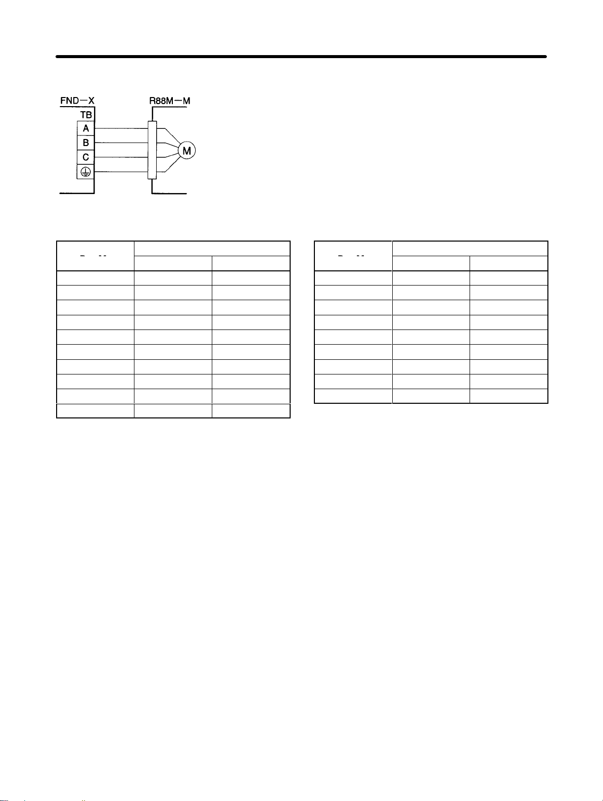
Design and Installation Chapter 2
D Wiring Power Cables
Red
White
Blue
Green
D Power Cable Wire Sizes
mm
Wire size
2
AWG
Model
R88M-
M20012 1.25 AWG16
M40012 1.25 AWG16
M70012 1.25 AWG16
M1K112 2 AWG14
M1K412 2 AWG14
M1K812 2 AWG14
M20020 0.9 AWG18
M40020 1.25 AWG16
M70020 1.25 AWG16
M1K120 1.25 AWG16
Model
R88M-
M1K820 3.5 AWG12
M2K220 3.5 AWG12
M06040 0.9 AWG18
M12040 0.9 AWG18
M20040 0.9 AWG18
M40040 0.9 AWG18
M70040 1.25 AWG16
M1K140 1.25 AWG16
M2K040 3.5 AWG12
mm
Wire size
2
AWG
2-44
Page 71

C
Design and Installation Chapter 2
2-2-2 Control Circuitry Terminal Wiring
DIO Position Drivers
H Control Signal Connector (CN1: CONT) Pin Arrangement
2 CWL
4 RUN
6 RESET
8
+JOG
10 TEACH
12 P.IN1
14 P.IN3
16 P.IN5
18
P.IN7 Position 7
CW
limit in
put
RUN
command
reset
Alarm
+JOG
operation
Teach
Point
selection
/Position 1
Point
selection 3
/Position 3
Point
selection 5
/Position 5
-
1
1 CCWL
3 ORG
5START
7 SEARCH
9
–JOG
11 P.IN0
13 P.IN2
15 P.IN4
17 P.IN6
CCW limit
input
Origin
proximity
Start
search
Origin
–JOG
operation
Point
selection 0
/Position 0
Point
selection 2
/Position 2
Point
selection 4
/Position 4
Point
selection 6
/Position 6
20
STOP
22 READY
24 ORGSTP
26 RUNON
28 ALM
30
P.OUT1
32 P.OUT3
34 P.OUT5
36 +24V
Deceleration
stop
Ready
Origin
stop
Motor
running
Alarm
output
Point
1/ Position
selection
Point
3/ Position
selection
Point output
5
+24-VDC
power supply input for
control
2
output
4
19 OGND
21
BO
23 S.COM
25 T.COM
27 INP
29 P.OUT0
31
P.OUT2
33 P.OUT4
35 P.OUT6
Output
ground
Brake
output
Origin
search
completed
Teaching
completed
Positioning
completed
Point
output
0/ Position
selection
Point
2/ Position
selection
Point
4/ Speed
selection
Point output
6
1
output
3
output
D Connectors Used
Sumitomo 3M Receptacle at Position Driver 10236-6202JL
Soldered plug at cable side 10136-3000VE
Case at cable side 10336-52A0-008
CompoBus/S Position Drivers
H CompoBus/S Communications Terminal Block (CN1: CONT) Pin
Arrangement
Signal Name Functions
BD H CompoBus/S serial line (+)
BD L
CompoBus/S serial line (–)
D I/O Allocation
The FND-X has 16 input points and 16 output points.
These are the terminals for connecting
p
ompoBus/S communications cables.Be
careful to connect the polarities correctly.
2-45
Page 72

Design and Installation Chapter 2
IN (16 Input Points)
I/O allocation Signal Name
OUT0 RUN RUN command
OUT1 START START
OUT2 RESET Alarm reset
OUT3 SEARCH Origin search
OUT4 +JOG +JOG operation
OUT5 –JOG –JOG operation
OUT6 TEACH Teach
OUT7 STOP (see note 2) Deceleration stop
OUT8 P. IN0 Point selection 0/Position 0
OUT9 P. IN1 Point selection 1/Position 1
OUT10 P. IN2 Point selection 2/Position 2
OUT11 P. IN3 Point selection 3/Position 3
OUT12 P. IN4 Point selection 4/Position 4
OUT13 P. IN5 Point selection 5/Position 5
OUT14 P. IN6 Point selection 6/Position 6
OUT15 P. IN7 Position 7
OUT (16 Output Points)
I/O allocation Signal Name
IN0 BO Brake output
IN1 READY READY
IN2 S.COM Origin search completed
IN3 ORGSTP Origin stop
IN4 T.COM Teaching completed
IN5 RUNON Motor running
IN6 INP Positioning completed
IN7 ALM Alarm
IN8 P. OUT0 Point output 0/Position selection 1
IN9 P. OUT1 Point output 1/Position selection 2
IN10 P. OUT2 Point output 2/Position selection 3
IN11 P. OUT3 Point output 3/Position selection 4
IN12 P. OUT4 Point output 4/Speed selection
IN13 P. OUT5 Point output 5
IN14 P. OUT6 Point output 6
IN15 --- Not used
Note 1. The I/O allocation indicates the word allocation for the Master Unit.
Note 2. The
Servomotor cannot be driven if the deceleration stop signal is OFF for the external control
input (CN4-4) or the CompoBus/S input (OUT7).
2-46
Page 73

Design and Installation Chapter 2
H External Control Signal Connectors (CN4: LIMIT) Pin Arrangement
Brake
output
Output
ground
2 CWL
4STOP
6
8
CW limit
Deceleration
stop
(see note)
1 CCWL
3 ORG
5
7 +24 V
CCW limit
Origin
proximity
+24-VDC
power supply input for
control
8BO
9
10
11
12
13
14 OGND
D Connectors Used
Sumitomo 3M Receptacle at Position Driver 10214-6202JL
Soldered plug at cable side 10114-3000VE
Case at cable side 10314-52A0-008
Note The Servomotor cannot be driven if the deceleration stop signal if OFF for the external control
input (CN4-4) or the CompoBus/S input (OUT7).
2-47
Page 74

Design and Installation Chapter 2
H Control I/O Specifications
DIO
CN1-1 CN4-1 CCWL CCW limit input Inputs the + direction limit signal (sta-
CN1-2 CN4-2 CWL CW limit input Inputs the – direction limit signal (sta-
CN1-3 CN4-3 ORG Origin proximity Signal for mechanical origin setting IN17
CN1-4 OUT0 RUN RUN command Command for beginning power on to
CN1-5 OUT1 START START Begins positioning operation (rising
CN1-6 OUT2 RESET Alarm reset Alarm reset signal (rising edge en-
CN1-7 OUT3 SEARCH Origin search When RUN is ON (rising edge en-
CN1-8 OUT4 +JOG +JOG operation +JOG operation (status enabled) ON:
CN1-9 OUT5 –JOG –JOG operation –JOG operation (status enabled) ON:
CN1-10 OUT6 TEACH Teach When ORIGIN SEARCH is OFF (sta-
Compo
Bus/S
Signal Name Function and interface Internal
allocation
IN15
tus enabled)
ON: Drive possible
OFF: Motor stopped by limit
detection when driving in the + direction.
IN16
tus enabled)
ON: Drive possible
OFF: Motor stopped by limit detection
when driving in – direction.
IN0
motor (status enabled)
When OFF, error counter is cleared.
ON: Power ON to motor
OFF: Power OFF to motor
IN1
edge enabled)
ON: START
IN2
abled)
IN3
abled):
ON: Origin search begins
When RUN is OFF (status enabled):
ON: Origin teaching awaited
IN4
Rotate
IN5
Rotate
IN6
tus enabled):
When UP-01 = 11 or 12, motor’s present position is taken for PTP data
when this bit turns ON.
When UP-01 = 13 or 14, P.IN0 to
P.IN7 is taken as positioning data
when this bit turns ON.
When RUN is OFF and ORIGIN
SEARCH is ON (status enabled):
Motor’s present position is taken for
origin compensation amount.
2-48
Page 75

ab ed)
,g
Design and Installation Chapter 2
DIO Internal
CN1-11 OUT8 P.IN0 Point selection 0/
CN1-12 OUT9 P.IN1 Point selection 1/
CN1-13 OUT10 P.IN2 Point selection 2/
CN1-14 OUT11 P.IN3 Point selection 3/
CN1-15 OUT12 P.IN4 Point selection 4/
CN1-16 OUT13 P.IN5 Point selection 5/
CN1-17 OUT14 P.IN6 Point selection 6/
CN1-18 OUT15 P.IN7 Position 7 IN14
CN1-20 CN4-4
CN1-36 CN4-7 +24V +24-VDC power
CN1-19 CN4-14 OGND Output ground
CN1-21 CN4-8
CN1-22 IN1 READY Ready Outputs ready status for receiving
CN1-23 IN2 S.COM Origin search
CN1-24 IN3 ORGSTP Origin stop Output turns ON when positioning is
CN1-25 IN4 T.COM Teaching com-
CN1-26 IN5 RUNON Motor running Output turns ON when power is turned
CN1-27 IN6 INP Positioning com-
CN1-28 IN7 ALM Alarm Output indicates error occurrence at
Compo
Bus/S
OUT7
IN0
Function and interfaceNameSignal
Positioning data inputs (status en-
Position 0
Position 1
Position 2
Position 3
Position 4
Position 5
Position 6
STOP Deceleration stop Stops according to deceleration stop
supply input for
control
common
BO Brake output External brake timing signal output.
completed
pleted
pleted
abled)
When UP-01 = 11 or 12, PTP data No.
is input as positioning data. Range: 1
to 64, BCD input.
When UP-01 = 13 or 14, positioning
data is input. Range: 1 to 99, BCD input.
Taken in order, two digits at a time,
from the rightmost digits.
mode (falling edge enabled)
ON: Motor driven
OFF: Motor stopped
Power supply input terminal for control
input.
Output ground common for control input.
Output OFF when brake is operating.
ORIGIN SEARCH, ST
point selection signal input. Output
turns ON when positioning data is received or when motor rotation is completed.
Output turns ON when motor’s present
position is established.
stopped at mechanical origin position.
Output turns ON when teaching input
processing is completed.
ON to the motor.
Output turns ON when error counter
residual pulses are within the UP-07
(positioning completed range) setting.
the driver or motor. Output OFF when
an alarm occurs.
ART, TEACH, or
allocation
IN7
IN8
IN9
IN10
IN11
IN12
IN13
IN18
---
---
OUT14
OUT0
OUT1
OUT2
OUT3
OUT4
OUT5
OUT6
2-49
Page 76

g
ositioning data ( osition and s eed).
Design and Installation Chapter 2
DIO Internal
CN1-29 IN8 P.OUT0 Point output 0/
CN1-30 IN9 P.OUT1 Point output 1/
CN1-31 IN10 P.OUT2 Point output 2/
CN1-32 IN11 P.OUT3 Point output 3/
CN1-33 IN12 P.OUT4 Point output 4/
CN1-34 IN13 P.OUT5 Point output 5 OUT12
CN1-35 IN14 P.OUT6 Point output 6 OUT13
Compo
Bus/S
Position selection
1
Position selection
2
Position selection
3
Position selection
4
Speed selection
Function and interfaceNameSignal
When UP-01 = 11 or 12:
Outputs (BCD) point No. during waiting or execution.
When UP-01 = 13 or 14:
Outputs request signal for receiving
positioning data (position and speed).
The output ON time is set for PP-26
(selection signal output time).
allocation
OUT7
OUT8
OUT9
OUT10
OUT11
Note The “internal allocations” are the numbers allocated in the CPU Unit.
2-50
Page 77

Design and Installation Chapter 2
H Control Input Details
DIO CN1-1 CompoBus/S CN4-1
CCWL CCW limit N.C. condition
• Pin
No. 1 is the plus (+) direction limit input signal. When this signal is not being input (ON), the motor
cannot be rotated in the plus (+) direction.
• If
this signal turns OFF during motor rotation in the plus (+)
ing to the PP-25 (alarm selection) setting.
DIO CN1-2 CompoBus/S CN4-2
CWL CW limit N.C. condition
• Pin
No. 2 is the minus (–) direction limit input signal. When this signal is not being input (ON), the motor
cannot be rotated in the minus (–) direction.
• If
this signal turns OFF during motor rotation in the minus (–) direction, the motor will be stopped ac
cording to the PP-25 (alarm selection) setting.
DIO CN1-3 CompoBus/S CN4-3
ORG Origin proximity N.O. condition
• Pin No. 3 is the input for determining the mechanical origin.
direction, the motor will be stopped accord
-
-
• When
an origin search is executed, operation stops
determined
after the origin proximity signal turns from
at the motor’s Z-phase position and the origin is
ON to OFF during motor rotation in the direction
set by PP-19 (origin search direction).
• When PP-06 and PP-07 (leftmost and rightmost digits for the origin compensation amount) are set,
positioning
will be executed from this position by the amount set for origin compensation, and then that
compensated position will be taken as the mechanical origin.
DIO CN1-4 CompoBus/S OUT0
RUN RUN command N.O. condition
The pin No. 4 signal input turns ON the power to drive the motor and begins motor operation. If this
signal is not input (turned ON), the motor cannot be driven.
DIO CN1-5 CompoBus/S OUT1
START START N.O. condition
• The pin No. 5 signal input executes the specified positioning (point No. input or direct input).
• When
this signal is input (turned ON), the motor is operated
and positioning is executed based on the
positioning data.
DIO CN1-6 CompoBus/S OUT2
RESET Alarm reset N.O. condition
• This is the alarm’s external reset signal.
• When this signal is input (turned ON), the alarm is cleared and the alarm output is turned ON. (The
alarm will not be cleared, however, if the alarm condition remains in effect.)
• If
this signal is input under normal conditions (i.e., when no alarm is generated), the motor is deceler
ated to a stop according to the deceleration time.
• When positioning is being executed according to PTP data, the point number is taken again.
• When an alarm is generated, remove the cause of the alarm before beginning operation again. For
safety’s sake, turn OFF the RUN command before inputting the alarm reset signal.
2-51
-
Page 78

Design and Installation Chapter 2
DIO CN1-7 CompoBus/S OUT3
SEARCH Origin search N.O. condition
• The pin No. 7 signal input begins an origin search or origin teaching operation.
• When
• When
DIO CN1-8 CompoBus/S OUT4
+JOG +JOG operation N.O. condition
• The pin No. 8 signal input rotates the motor in the + JOG direction at the JOG speed.
• While this signal is being input (i.e., while it is ON), the motor rotates in the forward direction at the
DIO CN1-9 CompoBus/S OUT5
–JOG –JOG operation N.O. condition
• The pin No. 9 signal input rotates the motor in the – JOG direction at the JOG speed.
• While this signal is being input (i.e., while it is ON), the motor rotates in the reverse direction at the
DIO CN1-10 CompoBus/S OUT6
TEACH Teach N.O. condition
this signal is input (turned ON) while RUN is ON, an origin search operation is executed. (The
motor rotates in the direction set in PP-19 (origin search direction).
this signal is input (turned ON) while RUN is OFF
teaching
be
amount.
speed set in PP-16 (JOG speed).
speed set in PP-16 (JOG speed).
(TEACH) signal is turned ON while the origin search signal is ON, the position at that time will
automatically taken into PP-06/PP-07 (origin compensation
, an origin teaching operation is executed. If the
amount) as the origin compensation
D Teaching [Origin established, UP-01 (Control Mode) = 11 or 12, Origin search
signal OFF]
• This is the signal input for automatically taking the PTP data’s position data.
• When
this signal is
position data for the PTP data (Pd-jj) selected by the point selection signal.
input (turned ON), the motor’s present value is taken as an absolute value to the
D Taking Direct Positioning Data [Origin established, UP-01 (Control Mode) = 13 or
14, RUN command OFF, origin search signal OFF]
• This is the signal input for taking the positioning data (position, speed) from the control input.
• When this signal is input (turned ON), the position and speed data are taken sequentially from the
positioning data inputs (P.IN 0 to 7), two digits at a time, beginning from the rightmost digits.
• The position and speed selection signals (P.OUT 0 to 4) are output as data request signals.
D Origin Teaching [Origin established, RUN command OFF, origin search signal ON]
• This is the input signal for automatically taking the origin compensation amount.
• When this signal is input (turned ON), the motor’s present value is taken into PP-06/PP-07 (origin
compensation
version.
amount) as the origin compensation amount, at the encoder/resolver resolution con
-
2-52
Page 79

Design and Installation Chapter 2
DIO CN1-11 to 18 CompoBus/S OUT8 to 15
P.IN0 to 7 Point selection / Position data N.O. condition
D Point Selection 0 to 6 [UP-01 (Control Mode) = 11 or 12]
• This is the signal input for selecting positioning data from PTP data.
• The range of data is 1 to 64, in BCD.
• Point
selections 0 to 3 become the data input for digit 100, and point selections 4 to 6 become the data
input for digit 101.
Example: When point No. 12 is set.
Point selection
6543210
0 0 1 0 0 1 0
0: OFF, 1: ON
D Positions 0 to 7 [UP-01 (Control Mode) = 13 or 14]
• This is the positioning data signal input.
range of data is 0 to 99, in
• The
• The
32 bits for the position data and the 8 bits for the speed data are taken eight bits at a time. At
time
the position and speed selection signals (P
fresh the input data according to the data request signals.
• If the speed is set to “0,” it will be taken as 100%.
DIO CN1-20 CompoBus/S CN4-4 / OUT7
STOP Deceleration stop N.C. condition
• This is the signal input for forcibly stopping motor rotation.
• While this signal is not being input (ON), the motor cannot be driven.
BCD (up to a maximum of “F9,” for the position’
.OUT 0 to 4) are output as data request signals. Re
s leftmost digits only).
this
-
the
• With
CompoBus/S Position Drivers, the motor cannot be driven unless the external control signal
input (CN4-4) and the CompoBus/S input (OUT7) are both input.
• The method for stopping the motor depends on the set value for PP-24 (deceleration stop mode).
H Control Output Details
DIO CN1-21 CompoBus/S CN4-8 / IN0
BO Brake output
• Outputs a timing signal for applying the brake.
• Set UP-16 to select either a dynamic brake (= 0) or an electromagnetic brake (= 1, 2, or 3).
these terminals as a timing signal for the dynamic brake when using both a dynamic brake and an
• Use
electromagnetic
in the example on the following page.
• When
UP-16 (brake mode) is set to 1, 2, or 3 (brake retention), the timing signal for applying the elec
tromagnetic
value
under the following circumstances, the output will be turned OFF and the electromagnetic brake
will be operated.
brake, and control the electromagnetic
brake using an external sequence as shown
brake is output. If the motor’s rotation speed falls below the UP-28 (brake-ON r/min) set
2-53
-
Page 80

Design and Installation Chapter 2
S When the RUN signal has been turned OFF.
S When an error shutting OFF the power to the motor has occurred.
S When a deceleration stop turns OFF while PP-24 (deceleration stop mode) is set to 0 (free-run
stop).
• When
UP-16 is set to 0 (dynamic brake), the timing signal for applying the dynamic brake is output.
Under the following circumstances the output is turned OFF and the dynamic brake is operated.
S When the RUN signal has been turned OFF.
S When an error shutting OFF the power to the motor has occurred.
S When a deceleration stop turns OFF while PP-24 (deceleration stop mode) is set to 0 (free-run
stop).
Electromagnetic Brake Wiring and Operational Sequence
• Wiring
AC Servomotor
Brake
Protectively
separated
(See note)
24 VDC 24 VDC
Note With
2-54
the CompoBus/S Position Drivers, outputs are made to CN4 (LIMIT). BO (CN4 to 8) and
OGND (CN4 to 14) are provided. For controlling brake drive bits, use the CN4 to CN8 pin out
-
puts.
Page 81

Design and Installation Chapter 2
• Operational Sequence
RUN
Alarm reset (RESET)
Alarm (ALM)
Power to motor
Brake output (BO)
Motor operation (speed)
UP-28 (brake-ON r/min)
Power ON
Note
1
Power ON
Note 2
Note 1. When the motor is stopped, the brake output turns OFF in approximately 2.4 ms.
Note 2. When the motor is stopped, the brake output turns OFF in approximately 0.8 ms.
Dynamic Brake Wiring and Operational Sequence
• Wiring
AC Servomotor
(See note)
Protectively
separated
24 VDC
Note With
the CompoBus/S Position Drivers, outputs are made to CN4 (LIMIT). BO (CN4 to 8) and
OGND
(CN4
to 14) are provided. For controlling dynamic brake drive bits, use the CN4 to CN8
pin outputs.
Select an XB relay that meets the following conditions.
1. The relay switching current must be greater than the maximum instantaneous current.
2. The relay coil input voltage must be 24 V.
3. The
contacts must open (releasing the brake) within 100 ms after the 24-V coil input starts to flow
.
2-55
Page 82

Design and Installation Chapter 2
4. If
there is no relay that satisfies these conditions (e.g., when connecting a motor or 1
connect resistance R using the following equation.
Set the resistance R so that the following equation is met.
1[V]
I
Ne f
XB
1
R
1000[mV]
IXB = Relay switchable current [A]
Ne = Motor inductive voltage [mV/(r/min)]
f = Motor speed (r/min)
The stopping time t when using the above resistance can be calculated as follows:
J (2R 2r *) 1000
t
Ne
K
T
kW or more),
Note The table in
J = Motor rotor inertia [kgm
K
= Motor torque constant [ Nm/A]
T
Chapter 5
give the internal resistance for the M Series as (2R + r).
2
]
Ne = Motor inductive voltage [mV/(r/min)]
r = Motor coil resistance [Ω]
R = Resistance [Ω]
When
using an OMRON L
Y2-D Relay for XB, use the following table for reference to keep the switching
capacity to 10 A or less.
Motor model number (R88M-) Resistance R Stopping time t:
Instantaneous maximum speed to 0 r/min
U1K030H, U1K030V, U1K030T, U1K030X,
U1K530H, U1K530V, U1K530T, U1K530X,
U2K030H, U2K030V, U2K030T, U2K030X
H1K130 15 Ω, 20 W 5 s at an inertia ratio of x10
H75030 12 Ω, 20 W 4.5 s at an inertia ratio of x10
H50030 9 Ω, 20 W 3 s at an inertia ratio of x10
M2K040, M1K140, M2K220, M1K820,
M1K120, M1K812, M1K412, M1K112
5 Ω, 20 W 2 to 3 s at an inertia ratio of x10
7 Ω, 20 W 2 to 5 s at an inertia ratio of x3
2-56
Page 83

Design and Installation Chapter 2
• Operational Sequence
RUN
Alarm reset (RESET)
Alarm (ALM
Power to motor
Brake output (BO)
Motor operation (speed)
DIO CN1-22 CompoBus/S IN1
READY READY
• This
)
Power ON Power ON
output turns ON when the input signal processing is completed and the origin search, start, teach,
and point selection signal inputs are ready.
• The
output turns
OFF when position data is taken and positioning begins, and turns ON when the pro
cessing is completed. The time set for HP-46 (positioning completed timer) must be OFF.
• While this signal is OFF, any START signal that is input will be invalid.
Using Both Electromagnetic and Dynamic Brakes
• Wiring
-
To PC
(See note.)
24 VDC
Note CN4
(LIMIT) is used for models supporting CompoBus/S (B0 = CN4-8, OGND = CN4-14). Control
the dynamic brake drive relay using the output on pin CN4-8.
24 VDC
24 VDC
AC Servomotor
Brake
2-57
Page 84

Design and Installation Chapter 2
• Operational Sequence
RUN
Alarm reset (RESET)
Alarm (ALM
Power to motor
Brake output (BO)
RUN-ON
Electromagnetic brake
(XB2, See note.)
Motor operation (speed)
Note The motor’s holding brake
DIO CN1-23 CompoBus/S IN2
S.COM Origin search completed
)
Power ON Power ON
may be damaged if it is applied during high-speed operation. Adjust
TB1 and TB2 so that the speed has been suf
ficiently
reduced before the holding brake is applied.
• This output turns ON when the mechanical origin is established.
• The output conditions are as follows:
When
a motor with an absolute-value encoder is connected, the signal turns ON when the power
supply is input.
When a motor with an incremental encoder or resolver is connected:
When
UP-01 (control mode) is 1
When
UP-01 (control mode) is 12 or 14, the signal turns ON when the power supply is
DIO CN1-24 CompoBus/S IN3
ORGSTP Origin stop
1 or 13, the signal turns ON after origin search is completed.
The output turns ON when the motor is stopped at the mechanical origin.
DIO CN1-25 CompoBus/S IN4
T.COM Teaching completed
• This output turns ON when the teaching input processing is completed.
• The output turns OFF when the teaching input turns OFF.
2-58
input.
Page 85

Design and Installation Chapter 2
DIO CN1-26 CompoBus/S IN5
RUNON Motor running
This output turns ON when the RUN command is input to the motor and power begins to flow to the
motor.
DIO CN1-27 CompoBus/S IN6
INP Positioning completed
• This
output turns ON
range) setting.
• The output turns OFF when positioning begins.
when error counter residual pulses are within the UP-07 (positioning completed
• After positioning is completed, the
output remains ON until the time set for HP-46 (positioning com
pleted timer) elapses.
DIO CN1-28 CompoBus/S IN7
ALM Alarm
• This output turns OFF when the driver detects an error.
• The
output is OFF when the power supply is turned ON, and the output turns ON when the initial pro
cessing is completed.
DIO CN1-29 to 35 CompoBus/S IN8 to 14
P.OUT0 to 6
Point output /
Position selection, speed selection
D Point Outputs 0 to 6 [UP-01 (Control Mode) = 11 or 12]
• The PTP data number that is waiting or being executed is output.
• The range of output data is 0 to 64, in BCD. (0: When point selection not input.)
• Point outputs 0 to 3 become the data output for digit 10
1
output for digit 10
.
Example: When point No. 12 is selected.
0
, and point outputs 4 to 6 become the data
-
-
Point output
6543210
0 0 1 0 0 1 0
0: OFF, 1: ON
D Position Selection 1 to 4 [UP-01 (Control Mode) = 13 or 14]
• This is the request signal output for obtaining positioning data.
• Refresh the data for positions 0 to 7 (P.IN 0 to 7) according to the data request signals.
• The
output ON time can be set by PP-26 (selection
inputting data from a source such as a Programmable Controller.
signal output time). Adjust this parameter when
2-59
Page 86

Design and Installation Chapter 2
H Control I/O Connections and External Signal Processing (DIO Position
Drivers)
+24
24 VDC
CCW
limit input
CW limit input
Origin proximity
RUN
V
Brake output
Maximum voltage:
24 VDC
Output
current:
40 mA
Origin search
completed
START
Alarm reset
Origin search
+JOG operation
–JOG operation
Teach
Point selection 0/ Position 0
Position 7
STOP
Origin stop
Teaching
completed
Motor running
Positioning
completed
Alarm
Point output 0
/ Position
selection 1
Note 1. The
Note 2. The
P.OUT 0.
2-60
24 VDC 8 mA
wiring for control inputs P
wiring for control inputs P
Point output 6
Output ground
.IN 1 to 6 is omitted. The input circuitry is the same as for P
.IN0.
.OUT 1 to 5 is omitted. The output circuitry is the same as for
Page 87

Design and Installation Chapter 2
H Control I/O Connections and External Signal Processing (CompoBus/S
Position Drivers)
+24
24 VDC
CCW
limit input
CW limit input
Origin proximity
Deceleration stop
24 VDC 8 mA
V
7
8
Brake output
14
Output ground
Maximum voltage:
24 VDC
Output
current:
40 mA
Note The Servomotor cannot be driven if the deceleration stop signal if OFF for the external control
input (CN4-4) or the CompoBus/S input (OUT7).
2-61
Page 88

Design and Installation Chapter 2
H Example: Connecting DIO Position Drivers to a Programmable
Controller
FND-X Position Driver
24 VDC +24 V
Programmable
Controller Output
Unit
Programmable
Controller Input
Unit
Brake
2-62
Page 89

Design and Installation Chapter 2
H Example: Connecting DIO Position Drivers to Thumbwheel Switch
(Positioning Data Designation by Direct Input)
Note 1. The
digits
but
other digits.
Note 2. The
pins 21 to 28 is omitted.
Note 3. Do
current prevention diodes
even when outputting the
position and speed data
from PLC Output Units.
Position
Position data
data
100 digit
1
digit
10
wiring for position data
102 to 105 is omitted,
it is the same as for
wiring for control
not remove the reverse-
the
output
24 VDC
+24 V
FND-X Position Driver
Position data
6
10
digit
Position data
7
digit
10
Sign +/–
INC/ABS
Speed data
0
digit
10
Speed data
101 digit
2-63
Page 90

Design and Installation Chapter 2
2-2-3 W
Provide proper wire diameters, ground systems, and noise resistance when wiring terminal blocks.
iring T
erminal Blocks
H Wiring FND-X06j to X25j Terminal Blocks
Power supply inputs
Regeneration Resistor
connection terminals
Power cable
Red
White
Blue or Black
Green
2-64
Page 91

jjH-j
FND-XjjH-j: Single- hase 200/240 VAC (170
Regenerative Resistor connection terminals
R88A RR40030 Regenerative Resistor, which will
)
motors)
Design and Installation Chapter 2
Terminal
label
R
S
P
J
N Main circuit DC output Main circuit DC output terminal.
A Phases A and U motor output Red
B Phases B and V motor output White
C Phases C and W motor output Blue
Power supply input The commercial power supply input terminals for
Main circuit DC output
Regenerative Resistor connection terminals
Frame ground Green Ground (to 100 Ω or less). This terminal is
Name Function
the main circuit and the control circuits.
FND-X
to 264 V) 50/60 Hz
FND-XjjL-j: Single-phase 100/115 VAC (85 to
127 V) 50/60 Hz
Connector terminals for the R88A-RR20030 or
R88A-RR40030 Regenerative Resistor, which will
be required if there is excessive regenerative energy. (see note)
These are the output terminals to the Servomotor. Be careful to wire them correctly.
OMNUC Servomotors can be connected
to these terminals with R88A-CAUj
Cable (for U-series Servomotors) or
R88A-CAHj Cable (for H-series Servomotors
or
black
OMRON does not provide a cable to connect these terminals to OMNUC M-series
Servomotors, so the user must provide an
appropriate cable if an M-series Servomotor is used.
used for both motor output and power supply input.
: Single-phase 200/240 VAC (170
.
.
Note Refer
to
3-10 Regenerative Energy Absorption
for the methods to calculate regenerative energy
.
2-65
Page 92

Design and Installation Chapter 2
H Wiring FND-X50j Terminal Blocks
Control circuit power
supply inputs
Protectively
separated
Power cable
Red
White
Blue or Black
Green
Main power
supply inputs
Regeneration
Resistor
Ground (100 Ω or less)
2-66
Page 93

the control circuits
y
y
R
R88A-RR40030 R
ill
yg
OMNUC S
Design and Installation Chapter 2
Terminal
label
R0
S0
R
S
T
P
J1
J2
N Main circuit DC output Main circuit DC output terminal.
MC
COM
BO
BI1
BI2
A Phases A and U motor output Red
B Phases B and V motor output White
C Phases C and W motor output Blue
Control circuit power supply input The commercial power supply input terminals for
Main power supply input The commercial power supply input terminals for
Main circuit DC output
egenerativeResistor connectionterminals
Not used. Do not connect anything to these terminals and do
Frame ground Green Ground (to 100 Ω or less). This terminal is
Name Function
.
Single-phase 200/240 VAC (170 to 264 V) 50/60 Hz
the main circuits.
Three-phase 200/240 VAC (170 to 264 V) 50/60 Hz
Connector terminals for the R88A-RR20030 or
be required if there is excessive regenerative energy. In this case, remove the short bar between JP1
and JP2. (see note)
not remove the short bar between BI1 and BI2.
These are the output terminals to the Servomotor. Be careful to wire them correctly.
these terminals with R88A-CAUBj Cable
(for U-series Servomotors).
OMRON does not provide a cable to con-
or
black
nect these terminals to OMNUC M-series
Servomotors, so the user must provide an
appropriate cable if an M-series Servomotor is used.
used for both motor output and power supply input.
egenerativeResistor, which w
ervomotors can be connected to
Note Refer
to
3-10 Regenerative Energy Absorption
for the methods to calculate regenerative energy
2-67
.
Page 94

)
ut terminals
)
PE)
g
y
g
()
Design and Installation Chapter 2
H Terminal Block Current and Wire Sizes
The
following table shows the rated ef
also the sizes of the electrical wires.
D Position Drivers with 200-VAC Input (FND-XjjH-j)
Driver FND-X06H-j FND-X12H-j FND-X25H-j FND-X50H-j
Main power supply input terminals(R,S, T
Control circuit
power supply in-
rmin
p
(R0, S0)
Motor output terminals (A, B, C,
PE
Frame ground
terminal (PE)
l
Effective current 2.1 A 4.9 A 10.1 A 16 A
Wire size 0.75 mm
Tightening torque 1.3 N⋅m
Effective current --- 0.35 A
Wire size --- 0.75 mm
Tightening torque --- 1.3 N⋅m
Effective current 1.4 A 3.4 A 5.7 A 14.1 A
Wire size 0.75 mm
Tightening torque 1.3 N⋅m
Wire size 0.75 mm
Tightening torque 1.3 N⋅m
fective currents flowing to the Position Driver’s terminal block, and
2
2
2
1.25 mm
1.25 mm
1.25 mm
2
2
2
2
2.0 mm
2.0 mm
2
2
D Position Drivers with 100-VAC Input (FND-XjjL-j)
Driver FND-X06L-j FND-X12L-j
Main power supply input terminals (R, S)
Motor output terminals
(A, B, C, PE)
Frame ground terminal
(PE)
Effective current 2.9 A 3.3 A
Wire size 0.75 mm
Tightening torque 1.3 N⋅m
Effective current 1.4 A 2.1 A
Wire size 0.75 mm
Tightening torque 1.3 N⋅m
Wire size 0.75 mm
Tightening torque 1.3 N⋅m
2
2
2
H Wire Sizes and Allowable Current
The
following table shows allowable currents when there are three electrical wires. Use values equal to
or lower than the specified values.
D Heat-resistant Vinyl Wiring, UL1007, Rated Temperature 80°C (Reference Value)
AWG size Nominal cross-
sectional area
(mm2)
20 0.5 19/0.18 39.5 6.6 5.6 4.5
--- 0.75 30/0.18 26.0 8.8 7.0 5.5
18 0.9 37/0.18 24.4 9.0 7.7 6.0
16 1.25 50/0.18 15.6 12.0 11.0 8.5
14 2.0 7/0.6 9.53 23 20 16
12 3.5 7/0.8 5.41 33 29 24
10 5.5 7/1.0 3.47 43 38 31
Configuration
(wires/mm
2
Conductive
)
resistance
(Ω/km)
Allowable current (A) for
ambient temperature
40°C 50°C 60°C
2-68
Page 95

Design and Installation Chapter 2
2-2-4 Wiring for Noise Resistance
H Wiring Method for FND-X06j to -X25j
Noise resistance will vary greatly depending on the wiring method used. Resistance to noise can be
increased by paying attention to the items described below.
(Faulty
grounding, short-
circuit protection)
AC power supply
(Lightning surge
protection)
No-fuse
breaker
NFB
Surge
absorber
(Noise
protection)
Contactor
X1
Noise
123
filter
NF
E
(Noise
FND-X
protection)
TB
R
4
S
TB
A
B
C
Metal
R88M-U/H/M
duct
M
Fuse
CN2
(Electric
protection)
3.5mm
shock noise
Ground
(to 100
or less)
2
Ground
Ω
plate
2
mm2min.
Control
ground
board
Controller power supply
Thick power line
(3.5 mm
2
Machine
ground
)
(Electrical shock,
noise protection)
• Ground the motor’s frame to the machine ground when the motor is on a movable shaft.
• Use
a grounding plate for the frame ground for each Unit, as shown in the illustration, and ground to a
single point.
• Use
ground lines with a minimum thickness of 3.5 mm2, and arrange the wiring so that the ground lines
are as short as possible.
• If
no-fuse breakers are installed at the top and the power supply line
metal
tubes for wiring and make sure that there is adequate distance between the input
is wired from the lower duct, use
lines and the
internal wiring. If input and output lines are wired together, noise resistance will decrease.
• No-fuse
breakers,
surge absorbers, and noise filters (NF) should be positioned near the input terminal
block (ground plate), and I/O lines should be isolated and wired using the shortest means possible.
• Wire
the noise filter as shown at the left in the following illustration. The noise filter should be installed
at the entrance to the control panel whenever possible.
AC input
Ground
Right: Separate input and output
1
NF
2
3
E
4
AC output
AC input
Ground
AC output
Wrong: Noise not filtered effectively
1
NF
2
3
E
4
2-69
Page 96

Design and Installation Chapter 2
• Use twisted-pair cables for the power supply cables whenever possible, or bind the cables.
Twisted Wires Binding
R
Position
Driver
S
or
Binding
• Separate power supply cables and signal cables when wiring.
H Wiring Method for FND-X50H-j
Noise resistance will vary greatly depending on the wiring method used. Resistance to noise can be
increased by paying attention to the items described below.
(Lightning
surge
filter
(Noise
protection)
Contactor
grounding,
(Faulty
short-circuit
protection)
AC power supply
No-fuse
breaker
Surge
absorber
protection)
Noise
Position
Driver
Metal
(Noise
protection)
duct
CN2
(M.SEN)
Thick power line
(3.5 mm
Machine
ground
2
)
(Electrical shock,
noise protection)
Ground
(to 100 Ω or less)
(Electric
shock
noise
protection)
Ground
plate
Fuse
Control
ground
Protectively
separated
Controller power supply
board
• Ground the motor’s frame to the machine ground when the motor is on a movable shaft.
a grounding plate for the frame ground for each Unit, as shown in the illustration, and ground to a
• Use
single point.
• Use
ground lines with a minimum thickness of 3.5 mm2, and arrange the wiring so that the ground lines
are as short as possible.
• If
no-fuse breakers are installed at the top and the power supply line
metal
tubes for wiring and make sure that there is adequate distance between the input
is wired from the lower duct, use
lines and the
internal wiring. If input and output lines are wired together, noise resistance will decrease.
• No-fuse
breakers,
surge absorbers, and noise filters (NF) should be positioned near the input terminal
block (ground plate), and I/O lines should be isolated and wired using the shortest means possible.
2-70
Page 97
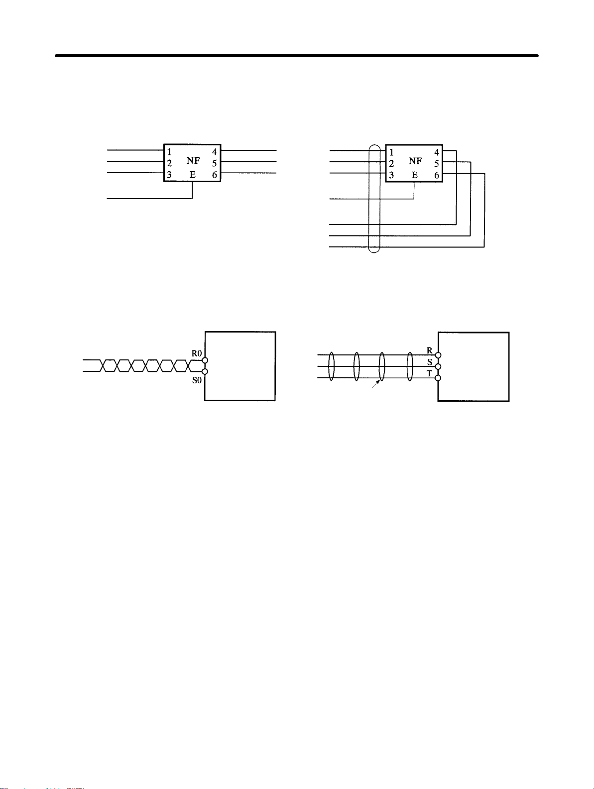
Design and Installation Chapter 2
• Wire
the noise filter as shown at the left in the following illustration. The noise filter should be installed
at the entrance to the control panel whenever possible.
Right: Separate input and output
AC inputs
Ground
AC outputs
Wrong: Noise not filtered effectively
AC inputs
Ground
AC outputs
• Use twisted-pair cables for the power supply cables whenever possible, or bind the cables.
Twisted Wires Binding
Position
Driver
Binding
Position
Driver
• Separate power supply cables and signal cables when wiring.
H Selecting Components
This section explains the standards for selecting the required components for improving noise resistance.
When selecting
performance, applicable range, and so on. For details regarding any of the recommended products
listed in the tables below, contact their respective makers.
D No-fuse Breakers
When
selecting no-fuse breakers, take into consideration the maximum output current and the inrush
current. The momentary maximum output for a servo system is approximately three times that of the
rated output, and a maximum output of three seconds can be executed. Therefore, select no-fuse
breakers
purpose
minal
for the number of shafts, other controllers, etc., to make the selection.
The
speed
ing the selection, take into consideration the entire inrush current for the system.
with an operating time of at least five seconds at 300% of the rated maximum output. General-
and low-speed no-fuse breakers are generally suitable. Refer to the table in
Blocks
for the power supply input currents for each motor
Position Driver inrush current flows at a maximum of 50 A for 20 ms when 200 V is
no-fuse breakers, a inrush current 7 to 8 times the rated current flows for 0.1
components, it is necessary to understand characteristics such as the capacity
2-2-3 W
iring T
er-
, and then add the current consumption
input. With low-
second. When mak
,
-
2-71
Page 98

Ind
l
y
Ind
l
g
Design and Installation Chapter 2
D Surge Absorbers
Use surge absorbers to absorb surges from power supply input lines due to lightning, abnormal voltages,
etc. When selecting surge absorbers, take into account the varistor
immunity,
and the amount of energy resistance. For 200-V
AC systems, use a varistor voltage of 470 V.
The surge absorbers shown in the following table are recommended.
voltage, the amount of surge
Maker Model Varistor
Matsushita
Electric
ustria
Ishizuka
Electric
Okaya
Electric
ustria
Note 1. The
ERZV10D471 (W) 470 V 775 V 1,250 A 45J 3 to 5 A
ERZV14D471 (W) 470 V 775 V 2,500 A 80J 3 to 10 A
ERZV20D471 (W) 470 V 775 V 4,000 A 150J 5 to 15 A
ERZV20E471 (W) 470 V 775 V 5,000 A 150J --- Block
Z10L471 470 V 773 V 1,000 A 15WSs 3 to 5 A
Z15L471 470 V 738 V 1,250 A 20WSs 3 to 5 A
Z21L471 470 V 733 V 3,000A 30WSs 5 to 10 A
Z25M471S 470 V 810 V 10,000 A 235J --- Block
RSASV-781 BWZ-2A --- 783 V 1,000 A --- --RSASV-781 BXZ-2A --- 783 V 1,000 A --- --R-A-V-401-621BYR-2 --- 620 V 1,000 A --- ---
“(W)” for the Matsushita Electric Industrial products
voltage
Max. limit
voltage
Surge
immunity
resistance
indicates that they are UL- and CSA-
approved products.
Note 2. Refer to manufacturers documentation for operating details.
Note 3. The
surge immunity is for
a standard impulse current of 8/20 µs. If pulses are wide, either de
crease the current or change to a larger-capacity surge absorber.
Note 4. The
energy resistance is the value at 2 ms. At 700 V or less, high-energy pulses may not be
avoidable. In that case, use an insulated transformer or reactor for surge absorption.
Energy
Fuse
capacity
Type
Tester
Tester
Block
-
D Noise Filters for Power Supply Input
• Use
a noise filter for external noise attenuation and for the reduction of radiation noise
tion Driver.
• Select a noise filter with a rated current of at least double that of the Driver’s input current.
• The noise filters shown in the following table can be used for 40-dB attenuation of noise between
200 kHz and 30 MHz.
Maker Model Rated current Remarks
Tokin
Note 1.
LF-210N 10 A
LF-215N 15 A
LF-220N 20 A
LF-315K 15 A
LF-325K 25 A
For attenuating noise in a low-frequency band of less than 200
For single phase
For three phase
kHz, use an insulated trans
former and a noise filter.
Note 2. For
attenuating noise in a high-frequency band of more than 30
MHz, use a ferrite core and a
high-frequency noise filter employing a through-type capacitor.
2-72
from the Posi
-
-
Page 99

Design and Installation Chapter 2
D Noise Filters for Servomotor Output
• For Servomotor output lines, use a filter type without a built-in capacitor.
• The following table shows recommended noise filters for Servomotor output lines.
Maker Model Rated current Remarks
Tokin
Fuji Electrochemical RN80UD --- 10 turns for radiation
LF-310KA 10 A
LF-320KA 20 A
ESD-R-47B --- EMI core for radiation
Note The same noise filter cannot be used for Servomotor output lines as for the power supply.
3-phase block noise filter
noise
noise
Caution Ordinary
!
necting
extremely
noise filters are created for a power supply frequency
an output of 10 kHz (the Position Driver’s PWM frequency)
of 50/60 Hz, so con
can generate an
high (approximately 100 time the normal) leakage current flow to the ca
pacitor in the noise filter and cause damage to the Position Driver.
D Surge Killers
Install
surge killers for loads
The following table shows types of surge killers and recommended products.
Type Features Recommended products
Diode Diodes are relatively small devices such as relays used
for loads when reset time is not an issue. The reset time
is increased because the surge voltage is the lowest
when power is cut OFF. Used for 24/48-VDC systems.
Thyristor
or
Varistor
Capacitor
+ resistor
Thyristor and varistor are used for loads when induction
coils are large, as in electromagnetic brakes, solenoids,
etc., and when reset time is an issue. The surge voltage
when power is cut OFF is approximately 1.5 times that
of the varistor.
Use capacitors and resistors for vibration absorption of
surge when power is cut OFF. The reset time can be
shortened by proper selection of the capacitor or resistor.
that have induction coils, such as relays, solenoids, brakes, clutches, etc.
Use a fast-recovery diode with a
short reverse recovery time.
Fuji Electric Co., ERB44-06 or equivalent
Select varistor voltage as follows:
24-VDC system varistor: 39 V
100-VDC system varistor: 200 V
100-VAC system varistor: 270 V
200-VAC system varistor: 470 V
Okaya Electric Industrial Co.
CR-50500 0.5 µF-50 Ω
CRE-50500 0.5 µF-50 Ω
S2-A-0 0.2 µF-500 Ω
-
-
Note Thyristors
and varistors are made by the following companies. Refer to manufacturers documen
tation for operating details.
Thyristors: Ishizuka Electronics Co.
Varistors: Ishizuka Electronics Co., Matsushita Electric Industrial Co.
-
2-73
Page 100

Design and Installation Chapter 2
D Contactors
When
selecting contactors, take into consideration the circuit’
mum current. The Position Driver inrush current is 50 A, and the momentary maximum current is
approximately twice the rated current. The following table shows the recommended contactors.
s inrush current and the momentary
maxi
-
Maker Model Rated
OMRON
G6C-2BND 10 A --- 24 VDC
LY2-D 10 A --- 24 VDC
G7L-2A-BUBJ 25 A --- 24 VDC, 200 to 240 VAC
J7AN-E3 15 A 120 A 24 VDC
LC1D25106 26 A --- 200 VAC
LP1D25106 26 A --- 24 VDC
current
Momentary maxi-
mum current
Coil voltage
D Leakage Breakers
• Select leakage breakers designed for inverters.
• Since switching operations take place inside the Position Driver, high-frequency current leaks from
the armature of the Servomotor. With inverter leakage breakers, high-frequency current is not detected, preventing the breaker from operating due to leakage current.
• When
• For detailed information on how to select leakage breakers, refer to the catalogs provided by the
• The following table shows the Servomotor leakage currents for each Driver model.
selecting leakage breakers, also remember to add the leakage current from devices other than
the
Servomotor
, such as machines using a switching power supply
, noise filters, inverters, and so on.
manufacturers.
Driver model Leakage current (direct)
(including high-frequency current)
FND-X06j/X12j 35 mA
FND-X25j 40 mA
FND-X50H 120 mA
Note 1. Leakage
current values shown above are for
0-P
0-P
0-P
motor power lines of 10 m or less. The values will
Leakage current (resistor-capacitor,
in commercial power supply fre-
quency range)
2 mA
rms
2 mA
rms
3 mA
rms
change depending on the length of power cables and the insulation.
Note 2. Leakage
current values shown above are for normal temperatures and humidity
will change depending on the temperature and humidity.
D Dynamic Brake Relay and Resistance
• Refer
to
Dynamic Brake Wiring and Operational Sequence
relay and resistance.
on
page
2-55 to select a dynamic brake
H Improving Encoder and Resolver Cable Noise Resistance
Signals
154 kHz, and the S-phase baud rate is 616K bits/s.
Signals from the resolver are analog voltage signals.
from the encoder are A-phase,
B-phase, or S-phase. The A-phase and B-phase frequency is
. The values
Follow the wiring methods outlined below to improve encoder/resolver noise resistance.
2-74
 Loading...