

Page 1
Cat. No. I566-E1-01
USER’S MANUAL
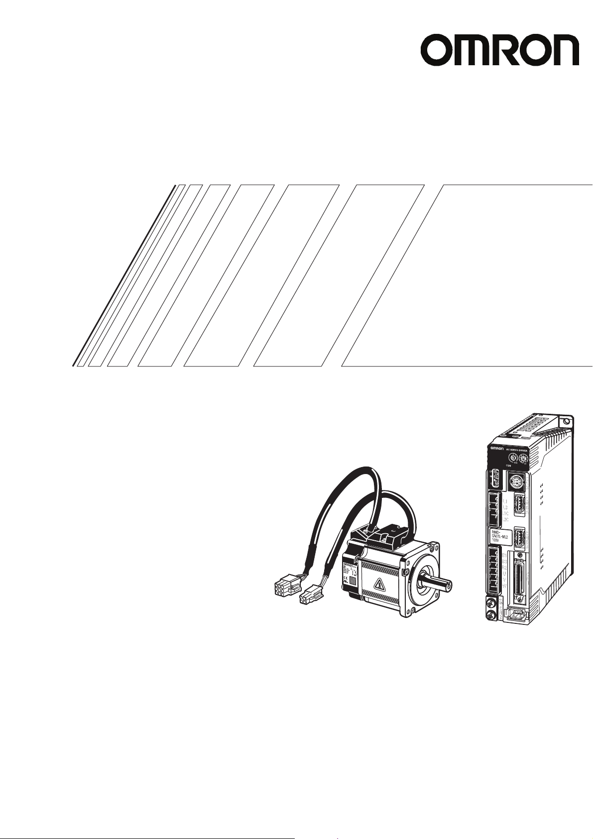
OMNUC G SERIES
R88M-G@
(AC Servomotors)
R88D-GN@-ML2
(AC Servo Drives)
AC SERVOMOTORS/SERVO DRIVES
WITH BUILT-IN MECHATROLINK-II COMMUNICATIONS
Page 2

Trademarks and Copyrights
•
Product names and system names in this manual are trademarks or registered trademarks of their
respective companies.
•
MECHATROLINK is a registered trademark of the MECHATROLINK Members Association.
© OMRON, 2008
All rights reserved. No part of this publication may be reproduced, stored in a retrieval system, or transmitted, in any
form, or by any means, mechanical, electronic, photocopying, recording, or otherwise, without the prior written permission of OMRON.
No patent liability is assumed with respect to the use of the information contained herein. Moreover, because OMRON is
constantly striving to improve its high-quality products, the information contained in this manual is subject to change
without notice. Every precaution has been taken in the preparation of this manual. Nevertheless, OMRON assumes no
responsibility for errors or omissions. Neither is any liability assumed for damages resulting from the use of the information contained in this publication.
Page 3

Introduction
Thank you for choosing the OMNUC G Series. This User’s Manual describes installation/wiring
methods and parameter setting procedures required for the operation of the OMNUC G Series as
well as troubleshooting and inspection methods.
Intended Readers
This manual is intended for the following personnel.
Those with knowledge of electrical systems (a qualified electrical engineer or the equivalent) as
follows:
Personnel in charge of introducing FA equipment
Personnel in charge of designing FA systems
Personnel in charge of managing FA systems and facilities
NOTICE
Introduction
This manual contains information necessary to ensure safe and proper use of the OMNUC G Series
and its peripheral devices. Please read this manual thoroughly and understand its contents before
using the products.
Please keep this manual handy for future reference.
Make sure this User’s Manual is delivered to the actual end user of the products.
1
Page 4
Read and Understand This Manual
Read and Understand This Manual
Please read and understand this manual before using the product. Please consult your OMRON
representative if you have any questions or comments .
Warranty and Limitations of Liability
WARRANTY
OMRON's exclusive warranty is that the products are free from defects in materials and workmanship
for a period of one year (or other period if specified) from date of sale by OMRON.
OMRON MAKES NO WARRANTY OR REPRESENTATION, EXPRESS OR IMPLIED, REGARDING
NON-INFRINGEMENT, MERCHANTABILITY, OR FITNESS FOR PARTICULAR PURPOSE OF THE
PRODUCTS. ANY BUYER OR USER ACKNOWLEDGES THAT THE BUYER OR USER ALONE HAS
DETERMINED THAT THE PRODUCTS WILL SUITABLY MEET THE REQUIREMENTS OF THEIR
INTENDED USE. OMRON DISCLAIMS ALL OTHER WARRANTIES, EXPRESS OR IMPLIED.
LIMITATIONS OF LIABILITY
OMRON SHALL NOT BE RESPONSIBLE FOR SPECIAL, INDIRECT, OR CONSEQUENTIAL
DAMAGES, LOSS OF PROFITS OR COMMERCIAL LOSS IN ANY WAY CONNECTED WITH THE
PRODUCTS, WHETHER SUCH CLAIM IS BASED ON CONTRACT, WARRANTY, NEGLIGENCE, OR
STRICT LIABILITY.
In no event shall the responsibility of OMRON for any act exceed the individual price of the product on
which liability is asserted.
IN NO EVENT SHALL OMRON BE RESPONSIBLE FOR WARRANTY, REPAIR, OR OTHER CLAIMS
REGARDING THE PRODUCTS UNLESS OMRON'S ANALYSIS CONFIRMS THAT THE PRODUCTS
WERE PROPERLY HANDLED, STORED, INSTALLED, AND MAINTAINED AND NOT SUBJECT TO
CONTAMINATION, ABUSE, MISUSE, OR INAPPROPRIATE MODIFICATION OR REPAIR.
2
Page 5
Read and Understand This Manual
Application Considerations
SUITABILITY FOR USE
OMRON shall not be responsible for conformity with any standards, codes, or regulations that app ly to
the combination of products in the customer's applicatio n or use of the products.
At the customer's request, OMRON will provide applicable third party certification documents identifying
ratings and limitations of use that apply to the products. This information by itself is not sufficient for a
complete determination of the suitability of the products in combination with the end product, machine,
system, or other application or use.
The following are some e xamples of applicat ions f or which particular attention mu st be giv en. This is not
intended to be an exhaustive list of all possible uses of the products, nor is it intended to imply that the
uses listed may be suitable for the products:
• Outdoor use, uses involving potential chemical contamination or electrical interference, or conditions
or uses not described in this manual.
• Nuclear energy control systems, combustion systems, railroad systems, aviation systems, medical
equipment, amusement machines, vehicles, safety equipment, and installations subject to separate
industry or government regulations.
• Systems, machines, and equipment that could present a risk to life or property.
Please know and observe all prohibitions of use applicable to the products.
NEVER USE THE PRODUCTS FOR AN APPLICATION INVOLVING SERIOUS RISK TO LIFE OR
PROPERTY WITHOUT ENSURING THAT THE SYSTEM AS A WHOLE HAS BEEN DESIGNED TO
ADDRESS THE RISKS, AND THAT THE OMRON PRODUCTS ARE PROPERLY RATED AND
INSTALLED FOR THE INTENDED USE WITHIN THE OVERALL EQUIPMENT OR SYSTEM.
PROGRAMMABLE PRODUCTS
OMRON shall not be responsible for the user's programming of a programmable product, or any
consequence thereof.
3
Page 6
Read and Understand This Manual
Disclaimers
CHANGE IN SPECIFICATIONS
Product specifications and accessories may be changed at any tim e based on improvements and other
reasons.
It is our practice to change model numbe rs when published ratings or features are changed, or when
significant construction changes are made. However, some specifications of the products may be
changed without any notice. When in doubt, special model n umber s may be assigned to fix or establish
key specifications f o r y our application on y our r equest. Please consult wit h y our OMR ON representativ e
at any time to confirm actual specifications of purchased products.
DIMENSIONS AND WEIGHTS
Dimensions and weights are nominal and are not to be used for manufacturing purposes, even when
tolerances are shown.
PERFORMANCE DATA
Performance data given in this manual is provided as a guide for the user in determining suitability and
does not constitute a warranty. It may represent the result of OMRON's test conditions, and the users
must correlate it to actual application require ments. Actual performance is subject to the OMRON
Warranty and Limitations of Liability.
ERRORS AND OMISSIONS
The information in this manual has been carefully checked and is believed to be accurate; however, no
responsibility is assumed for clerical, typographical, or proofreading errors, or omissions.
4
Page 7
Precautions for Safe Use
WARNING
Caution
Indicates a potentially hazardous situation which, if not
avoided, could result in death or serious injury.
Additionally, there may be severe property damage.
Indicates a potentially hazardous situation which, if not
avoided, may result in minor or moderate injury, or property
damage.
WARNING
Precautions for Safe Use
To ensure safe and proper use of the OMNUC G Series and its peripheral devices, read the “Precautions for
Safe Use” and the rest of the manual thoroughly to acquire sufficient knowledge of the devices, safety
information, and precautions before using the products.
Make sure this User’s Manual is delivered to the actual end users of the products.
Please keep this manual close at hand for future reference.
Explanation of Signal Words
The precautions indicated here provide important information for safety. Be sure to heed the information
provided with the precautions.
The following signal words are used to indicate and classify precautions in this manual.
Failure to heed the precautions classified as “Caution” may also lead to serious results. Always
heed these precautions.
Safety Precautions
This manual may include illustrations of the product with protective covers or shields removed in order to show
the components of the product in detail. Make sure that these protective covers and shields are put in place as
specified before using the product.
Consult your OMRON representative when using the product after a long period of storage.
Always connect the frame ground terminals of the Servo Drive and the Servomotor to 100 Ω
or less.
Incorrect grounding may result in electric shock.
Do not touch the inside of the Servo Drive.
Doing so may result in electric shock.
When turning OFF the main circuit power supply, turn OFF the RUN command (RUN) at the
same time. Residual voltage may cause the Servomotor to continue rotating and result in
injury or equipment damage even if the main circuit power supply is turned OFF externally,
e.g., with an emergency stop.
Do not remove the front cover, terminal covers, cables, or optional items while the power is
being supplied.
Doing so may result in electric shock.
5
Page 8
Precautions for Safe Use
Installation, operation, maintenance, or inspection must be performed by authorized
personnel.
Not doing so may result in electric shock or injury.
Wiring or inspection must not be performed for at least 15 minutes after turning OFF the
power supply.
Doing so may result in electric shock.
Do not damage or pull on the cables, place heavy objects on them, or subject them to
excessive stress.
Doing so may result in electric shock, stopping product operation, or burning.
Do not touch the rotating parts of the Servomotor during operation.
Doing so may result in injury.
Do not modify the product.
Doing so may result in injury or damage to the product.
Provide a stopping mechanism on the machine to ensure safety.
*The holding brake is not designed as a stopping mechanism for safety purposes.
Not doing so may result in injury.
Provide an external emergency stopping mechanism that can stop operation and shut off the
power supply immediately.
Not doing so may result in injury.
Do not come close to the machine immediately after resetting momentary power interruption
to avoid an unexpected restart.
Doing so may result in injury.
Take appropriate measures to secure safety against an unexpected restart.
Confirm safety after an earthquake has occurred.
Failure to do so may result in electric shock, injury, or fire.
Do not use external force to drive the Servomotor.
Doing so may result in fire.
6
Page 9
Precautions for Safe Use
WARNING
Caution
Caution
Do not place any flammable materials near the Servomotor, Servo Drive, or Regeneration
Resistor.
Doing so may result in fire.
Mount the Servomotor, Servo Drive, and Regeneration Resistor on metal or other nonflammable materials.
Failure to do so may result in fire.
Do not frequently and repeatedly turn the main power supply ON and OFF.
Doing so may result in product failure.
Use the Servomotors and Servo Drives in a specified combination.
Using them incorrectly may result in fire or damage to the products.
Do not store or install the product in the following places. Doing so may result in fire, electric
shock, or damage to the product.
Locations subject to direct sunlight.
Locations subject to temperatures outside the specified range .
Locations subject to humidity outside the specified range.
Locations subject to condensation as the result of severe changes in temperature.
Locations subject to corrosive or flammable gases.
Locations subject to dust (especially iron dust) or salts.
Locations subject to exposure to water, oil, or chemicals.
Locations subject to shock or vibration.
Do not touch the Servo Drive radiator, Servo Drive regeneration resistor, or Servomotor
while the power is being supplied or soon after the power is turned OFF.
Doing so may result in burn injuries.
Storage and Transportation Precautions
Do not hold the product by the cables or motor shaft while transporting it.
Doing so may result in injury or malfunction.
Do not place any load exceeding the figure indicated on the product.
Doing so may result in injury or malfunction.
Use the motor eye-bolts only for transporting the Servomotor.
Using them for transporting the machinery may result in injury or malfunction.
7
Page 10
Precautions for Safe Use
Caution
Installation and Wiring Precautions
Do not step on or place a heavy object on the product.
Doing so may result in injury.
Do not cover the inlet or outlet ports and prevent any foreign objects from entering the
product.
Covering them or not preventing entry of foreign objects may result in fire.
Be sure to install the product in the correct direction.
Not doing so may result in malfunction.
Provide the specified clearances between the Servo Drive and the control panel or with other
devices.
Not doing so may result in fire or malfunction.
Do not subject Servomotor shaft or Servo Drive to strong impacts.
Doing so may result in malfunction.
Be sure to wire correctly and securely.
Not doing so may result in motor runaway, injury, or malfunction.
Be sure that all the mounting screws, terminal screws, and cable connector screws are
tightened properly.
Incorrect tightening torque may result in malfunction.
Use crimp terminals for wiring.
Do not connect bare stranded wires directly to the protective ground terminal.
Doing so may result in burning.
Always use the power supply voltage specified in the User’s Manual.
An incorrect voltage may result in malfunction or burning.
Take appropriate measures to ensure that the specified power with the rated voltage and
frequency is supplied. Be particularly careful in places where the power supply is unstable.
An incorrect power supply may result in equipment damage.
Install external breakers and take other safety measures against short-circuiting in external
wiring.
Insufficient safety measures against short-circuiting may result in burning.
Take appropriate and sufficient shielding measures when installing systems in the following
locations. Failure to do so may result in damage to the product.
Locations subject to static electricity or other forms of noise.
Locations subject to strong electromagnetic fields and magnetic fields.
Locations subject to possible exposure to radioactivity.
Locations close to power supplies.
Connect an emergency stop cutoff relay in series with the brake control relay.
Failure to do so may result in injury or product failure.
Do not reverse the polarity of the battery when connecting it.
Reversing the polarity may damage the battery or cause it to explode.
8
Page 11
Operation and Adjustment Precautions
Caution
Caution
Confirm that no adverse effects will occur in the system before performing the test operation.
Not doing so may result in equipment damage.
Check the newly set parameters for proper operation before actually running them.
Not doing so may result in equipment damage.
Do not make any extreme adjustments or setting changes.
Doing so may result in unstable operation and injury.
Separate the Servomotor from the machine, check for proper operation, and then connect to
the machine.
Not doing so may cause injury.
When an alarm occurs, remove the cause, reset the alarm after confirming safety, and then
resume operation.
Not doing so may result in injury.
Precautions for Safe Use
Do not use the built-in brake of the Servomotor for ordinary braking.
Doing so may result in malfunction.
Do not operate the Servomotor connected to a load that exceeds the applicable load
moment of inertia.
Doing so may result in malfunction.
Maintenance and Inspection Precautions
Resume operation only after transferring to the new Unit the contents of the data required
for operation.
Not doing so may result in equipment damage.
Do not attempt to disassemble or repair any of the products.
Any attempt to do so may result in electric shock or injury.
9
Page 12
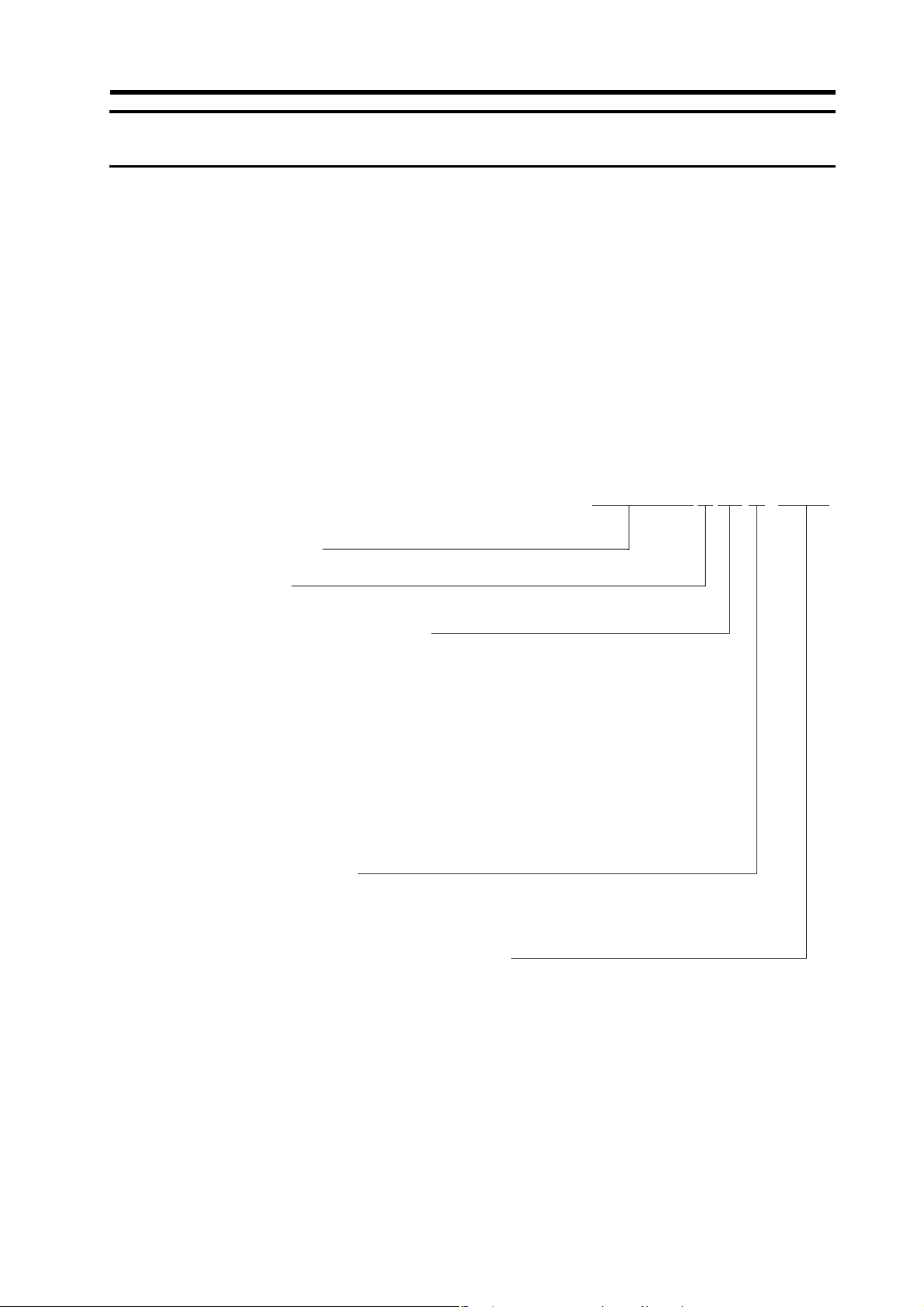
Precautions for Safe Use
(R88D-GN01H-ML2)
Location of warning label
Warning Label Position
Warning labels are located on the product as shown in the following illustration.
Be sure to follow the instructions given there.
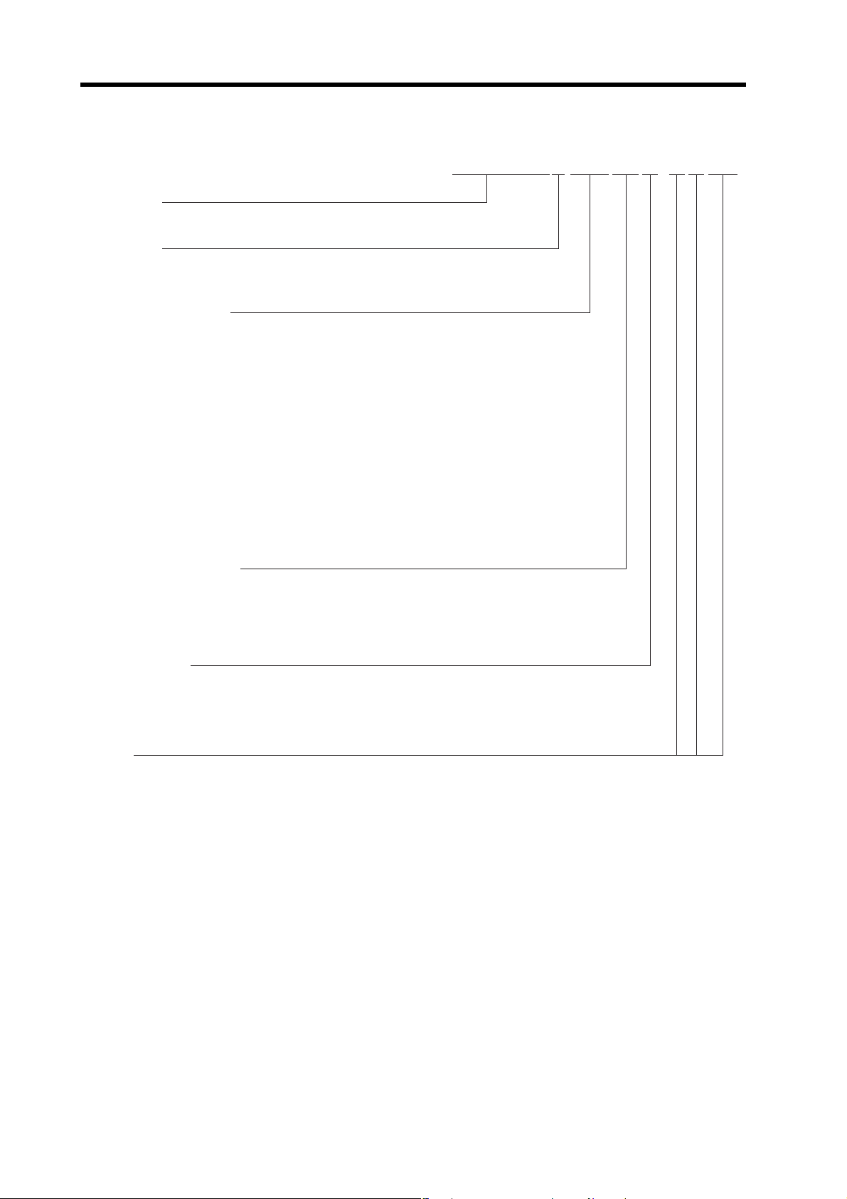
Warning Label Contents
Disposing of the Product
• Dispose of the batteries according to local ordinances and regulations. Wrap the batteries in tape
or other insulative material before disposing of them.
• Dispose of the product as industrial waste.
10
Page 13
Items to Check When Unpacking
R88D-GN01H-ML2
Power Supply V oltage
L : 100 VAC
H : 200 VAC
A5
:
50 W
01 : 100 W
02 : 200 W
04 : 400 W
08 : 750 W
10 : 1 kW
15 : 1.5 kW
20 : 2 kW
30 : 3 kW
50 : 5 kW
75 : 7.5 kW
Network Type
ML2 : MECHATROLINK-II Communications
OMNUC G-Series
Servo Drive
Drive Type
N
:
Network type
Applicable Servomotor Capacity
Items to Check When Unpacking
Check the following items after removing the product from the package.
• Has the correct product been delivered?
• Has the product been damaged in shipping?
Accessories Provided with Product
Safety Precautions document × 1
• No connectors or mounting screws are provided. They have to be prepared by the user.
• Should you find any problems (missing parts, damage to the Servo Drive, etc.), please contact
your local sales representative or OMRON sales office.
Understanding Servo Drive Model Numbers
The model number provides information such as the Servo Drive type, the applicable Servomotor
capacity, and the power supply voltage.
11
Page 14
Items to Check When Unpacking
R88M-GP10030H-BOS2
G-Series
Servomotor
Servomotor Capacity
Rated Rotation Speed
Motor Type
Blank: Cylinder type
P: Flat type
050:
100:
200:
400:
750:
900:
1K0:
1K5:
2K0:
3K0:
4K0:
4K5:
5K0:
6K0:
7K5:
10:
15:
20:
30:
50 W
100 W
200 W
400 W
750 W
900 W
1 kW
1.5 kW
2 kW
3 kW
4 kW
4.5 kW
5 kW
6 kW
7.5 kW
1,000 r/min
1,500 r/min
2,000 r/min
3,000 r/min
Applied V oltage
H:
L:
T:
S:
200 VAC with incremental encoder specifications
100 VAC with incremental encoder specifications
200 V AC with absolute encoder specifications
100 V AC with absolute encoder specifications
Option
Blank: Straight shaft
B:
O:
S2:
With brake
With oil seal
With key and tap
Understanding Servomotor Model Numbers
12
Page 15
Understanding Decelerator Model Numbers (Backlash = 3' Max.)
R88G-HPG14A05100PBJ
Decelerator for
G-Series Ser vomotors
Applicable Servomotor Capacity
050
100
200
400
750
900
1K0
1K5
2K0
3K0
4K0
4K5
5K0
6K0
7K5
: 50 W
:100 W
:200 W
:400 W
:750 W
:900 W
:1 kW
:1.5 kW
:2 kW
:3 kW
:4 kW
:4.5 kW
:5 kW
:6 kW
:7 kW
Backlash = 3’ Max.
Gear Ratio
05
09
11
12
20
21
25
33
45
:1/5
:1/9 (only frame number 11A)
:1/11 (except frame number 65A)
:1/12 (only frame number 65A)
:1/20 (only frame number 65A)
:1/21 (except frame number 65A)
:1/25 (only frame number 65A)
:1/33
:1/45
Flange Size Number
11A
14A
20A
32A
50A
65A
:@40
:@60
:@90
:@120
:@170
:@230
Motor Type
Blank
P
S
T
:3,000-r/min cylindrical Servomotors
:flat Servomotors
:2,000-r/min Servomotors
:1,000-r/min Servomotors
Backlash
B :3’ max.
Option
BlankJ:Straight shaft
:With key and tap
Items to Check When Unpacking
13
Page 16
Items to Check When Unpacking
R88G-VRSF09B100PCJ
Applicable Servomotor Capacity
050
100
200
400
750
: 50 W
:100 W
:200 W
:400 W
:750 W
Option
J :With key and tap
Backlash
C :15’ max.
Motor Type
BlankP:3,000-r/min cylindrical Servomotors
:flat Servomotors
Decelerator for
G-Series Ser vomotors
Backlash = 15’ Max.
Gear Ratio
05
09
15
25
:1/5
:1/9
:1/15
:1/25
Flange Size Number
B
C
D
:@52
:@78
:@98
Understanding Decelerator Model Numbers (Backlash = 15' Max.)
14
Page 17
About This Manual
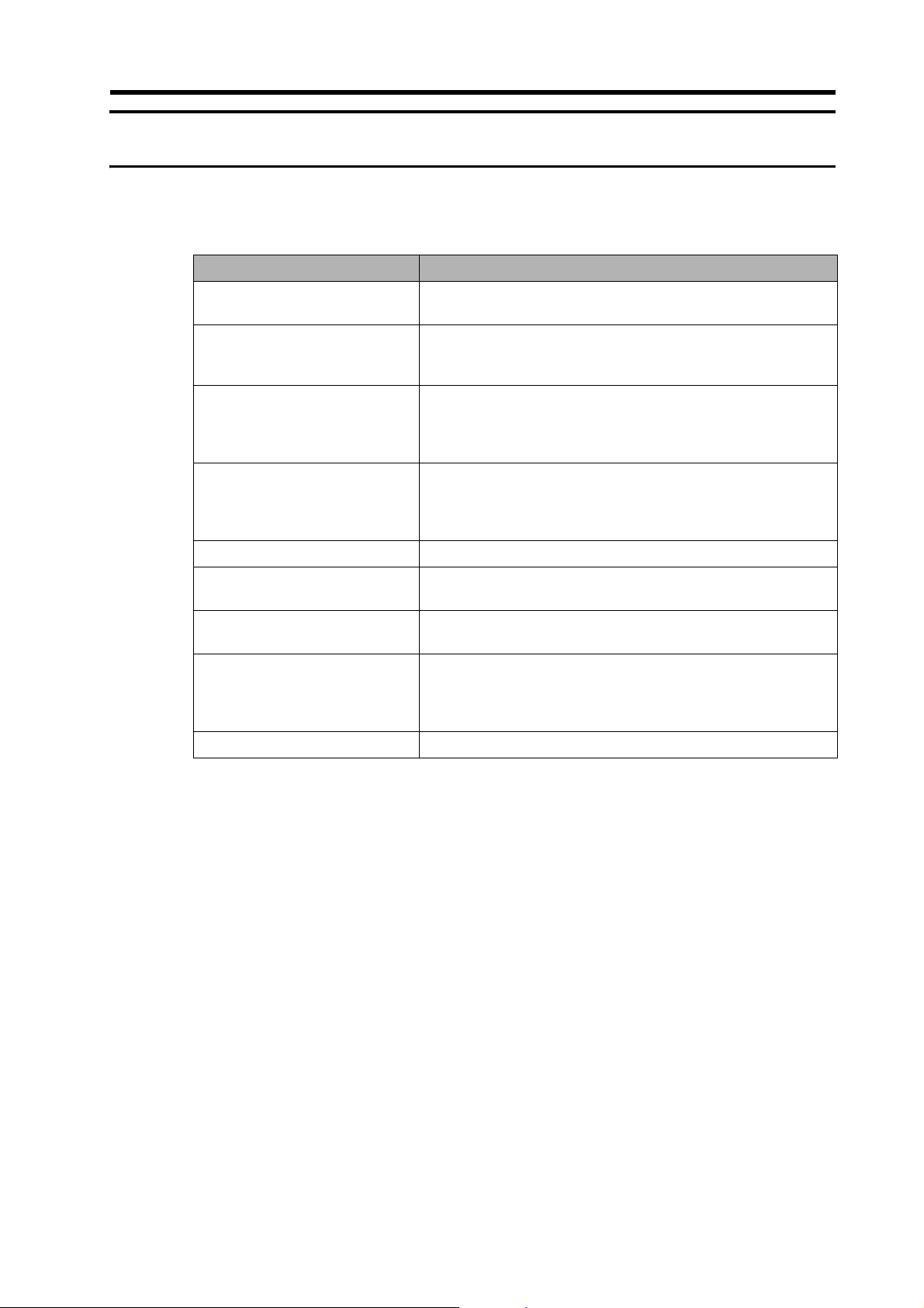
This manual consists of the following chapters. Refer to this table and chose the required chapters
of the manual.
About This Manual
Overview
Chapter 1
Chapter 2
Chapter 3 Specifications
Chapter 4 System Design
Chapter 5 Operating Functions Describes the control functions, parameter settings, and operation.
Chapter 6 Operation
Chapter 7 Adjustment Functions
Chapter 8 Troubleshooting
Chapter 9 Appendix Provides the parameter tables.
Features and System
Configuration
Standard Models and
Dimensions
Describes the features and names of parts of the product as well
as the EC Directives and the UL standards.
Provides the model numbers, external and mounting hole dimensions for Servo Drives, Servomotors, Decelerators, and peripheral
devices.
Provides the general specifications, characteristics, connector
specifications, and I/O circuit specifications for Servo Drives, and
the general specifications and characteristics for Servomotors, as
well as specifications for accessories such as encoders.
Describes the installation conditions for Servo Drives, Servomotors, and Decelerators, EMC conforming wiring methods, calculations of regenerative energy, and performance information on the
External Regeneration Resistor.
Describes operating procedures and operating methods for each
mode.
Describes gain adjustment function s, setting methods, and precautions.
Describes items to check for troubleshooting, error diagnoses using alarm LED displays and the countermeasures, error diagnoses
based on the operation status and the countermeasures, and periodic maintenance.
15
Page 18

Table of Contents
Introduction......................................................................................1
Read and Understand This Manual.................................................2
Precautions for Safe Use.................................................................5
Items to Check When Unpacking ....................................................11
About This Manual...........................................................................15
Chapter 1 Features and System Configuration
1-1 Overview...........................................................................................1-1
1-2 System Configuration.......................................................................1-2
1-3 Names of Parts and Functions.........................................................1-3
1-4 System Block Diagrams ...................................................................1-5
1-5 Applicable Standards........................................................................1-10
Chapter 2 Standard Models and Dimensions
2-1 Standard Models ..............................................................................2-1
2-2 External and Mounting Hole Dimensions .........................................2-23
Chapter 3 Specifications
3-1 Servo Drive Specifications................................................................3-1
3-2 Servomotor Specifications................................................................3-17
3-3 Decelerator Specifications................................................................3-32
3-4 Cable and Connector Specifications ................................................3-42
3-5 Parameter Unit Specifications..........................................................3-78
3-6 External Regeneration Resistor Specifications ................................ 3-79
3-7 Reactor Specifications......................................................................3-80
Chapter 4 System Design
4-1 Installation Conditions ......................................................................4-1
4-2 Wiring ...............................................................................................4-11
4-3 Wiring Conforming to EMC Directives.............................................. 4-26
4-4 Regenerative Energy Absorption......................................................4-44
16
Page 19

Table of Contents
Chapter 5 Operating Functions
5-1 Position Control................................................................................ 5-1
5-2 Speed Control .................................................................................. 5-4
5-3 Torque Control................................................................................. 5-7
5-4 Forward and Reverse Drive Prohibit................................................ 5-10
5-5 Brake Interlock ................................................................................. 5-11
5-6 Torque Limit ..................................................................................... 5-16
5-7 Soft Start .......................................................................................... 5-18
5-8 Acceleration/Deceleration Time Settings ......................................... 5-19
5-9 Moving Average Time ...................................................................... 5-20
5-10 Electronic Gear ................................................................................ 5-21
5-11 Speed Limit ...................................................................................... 5-22
5-12 Sequence Input Signals ................................................................... 5-23
5-13 Sequence Output Signals ................................................................ 5-25
5-14 Backlash Compensation .................................................................. 5-27
5-15 Overrun Protection........................................................................... 5-29
5-16 Gain Switching ................................................................................. 5-31
5-17 Speed Feed-forward ........................................................................ 5-38
5-18 Torque Feed-forward ....................................................................... 5-39
5-19 Speed Feedback Filter Selection ..................................................... 5-40
5-20 P Control Switching.......................................................................... 5-41
5-21 Torque Command Filter Time Constant........................................... 5-42
5-22 Notch Filter....................................................................................... 5-43
5-23 Adaptive Filter .................................................................................. 5-45
5-24 Instantaneous Speed Observer ....................................................... 5-48
5-25 Damping Control .............................................................................. 5-50
5-26 User Parameters.............................................................................. 5-55
5-27 Details on Important Parameters ..................................................... 5-86
Chapter 6 Operation
6-1 Operational Procedure..................................................................... 6-1
6-2 Preparing for Operation.................................................................... 6-2
6-3 Using the Parameter Unit................................................................. 6-8
6-4 Setting the Mode.............................................................................. 6-9
6-5 Trial Operation ................................................................................. 6-31
Chapter 7 Adjustment Functions
7-1 Gain Adjustment............................................................................... 7-1
7-2 Realtime Autotuning......................................................................... 7-3
7-3 Normal Mode Autotuning ................................................................. 7-9
7-4 Manual Tuning ................................................................................. 7-14
17
Page 20

Table of Contents
Chapter 8 Troubleshooting
8-1 Error Processing...............................................................................8-1
8-2 Alarm Table......................................................................................8-3
8-3 Troubleshooting................................................................................8-7
8-4 Overload Characteristics (Electronic Thermal Function).................. 8-20
8-5 Periodic Maintenance.......................................................................8-21
Chapter 9 Appendix
9-1 Parameter Tables.............................................................................9-1
18
Page 21

Chapter 1
Features and System Configuration
1-1 Overview............................................................ 1-1
Overview...............................................................................1-1
Features................................................................................1-1
1-2 System Configuration......................................... 1-2
1-3 Names of Parts and Functions........................... 1-3
Servo Drive Part Names .......................................................1-3
Servo Drive Functions...........................................................1-4
1-4 System Block Diagrams.....................................1-5
1-5 Applicable Standards......................................... 1-10
EC Directives........................................................................1-10
UL and CSA Standards.........................................................1-10
Page 22

1-1 Overview
1
Features and System Configuration
1-1 Overview
Overview
The OMNUC G Series AC Servo Drives (with built-in MECHATROLINK-II communications support)
are a series of Servo Drives supporting the MECHATROLINK-II high-speed motion field network.
When used with the MECHATROLINK-II Position Control Unit (CJ1W-NCF71 or CS1W-NCF71),
a sophisticated positioning control system can be made easily with one communications cable
connecting the Servo Drive and Controller.
With realtime autotuning, adaptive filter, notch filter, and damping control, you can set up a system
that provides stable operation by suppressing vibration in low-rigidity machines.
Features
Data Transmission Using MECHATROLINK-II Communications
When used with the MECHATROLINK-II Position Control Unit (CJ1W-NCF71 or CS1W-NCF71), all
control data between the Servo Drive and Controller can be exchanged through data
communications.
Since the various control commands are transmitted via data communications, Servomotor‘s
operational performance is maximized without being limited by interface specifications such as the
response frequency of the encoder feedback pulses.
This makes it possible to use the Servo Drive’s various control parameters and monitor data via a
host controller, allowing you to unify the system data control.
Suppressing Vibration of Low-rigidity Mechanisms during
Acceleration/Deceleration
The damping control function suppresses vibration of low-rigidity mechanisms or devices whose
ends tend to vibrate.
Two vibration filters are provided to enable switching the vibration frequency automatically
according to the direction of the rotation. Furthermore, the settings can be made easily by just
setting the vibration frequency and filter values, and you are assured of stable operation even if the
settings are inappropriate.
High-speed Positioning via Resonance Suppression Control
The realtime autotuning function automatically estimates the load inertia of the machine in realtime
and sets the optimal gain.
The adaptive filter automatically suppresses vibration caused by resonance.
Two independent notch filters make it possible to reduce the vibration of a mechanism with multiple
resonance frequencies.
Command Control Mode Switching
Operations can be performed by switching between two of the following control modes: Position
control, speed control, and torque control. Therefore, a variety of applications can be supported by
one Servo Drive.
1-1
Page 23
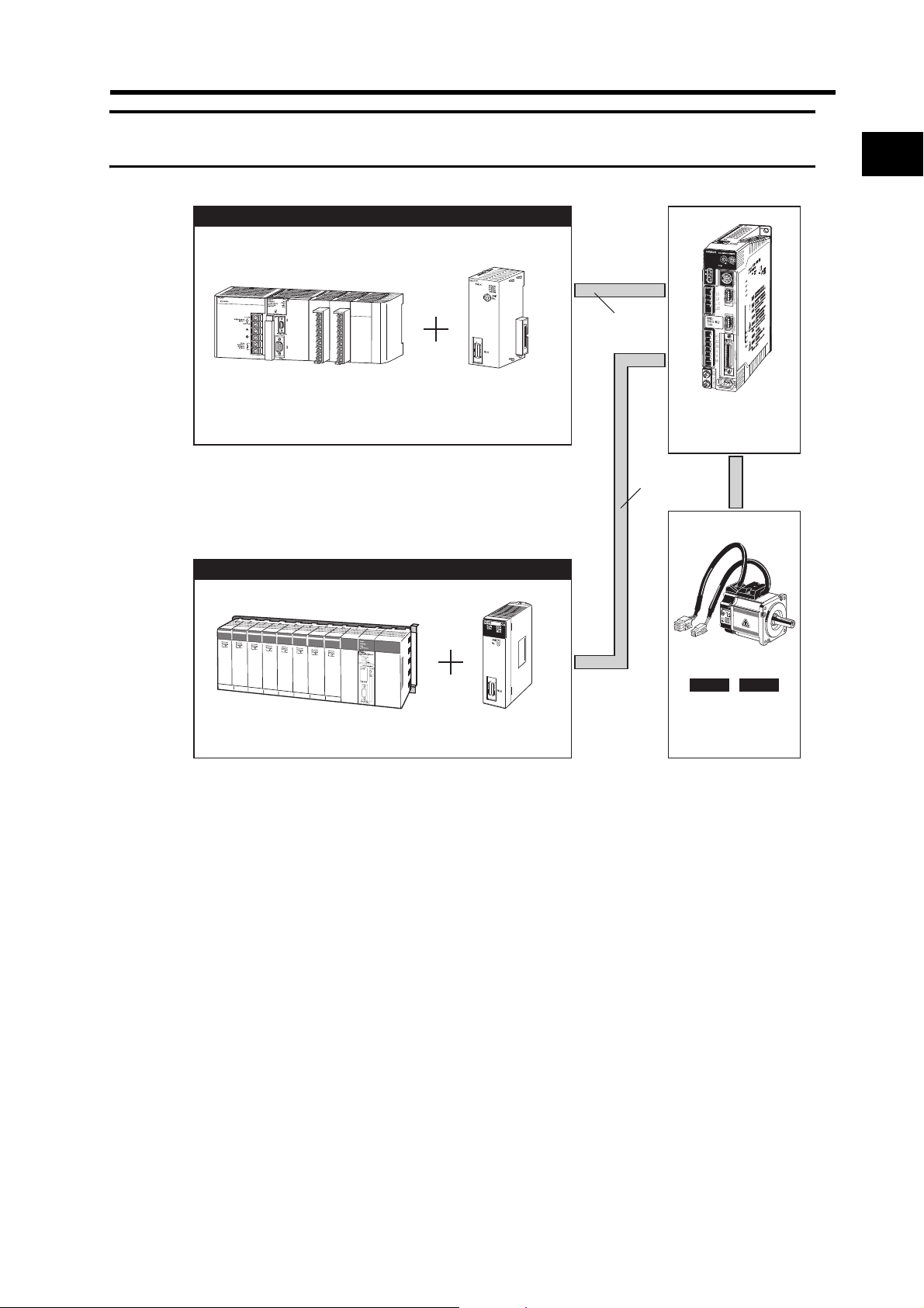
1-2 System Configuration
INCINC ABSABS
MECHATRO
LINK-II
Programmable Controller
SYSMAC CS1
Controller (MECHATROLINK-ll type)
Programmable Controller
SYSMAC CJ1
Position Control Unit
MECHATRO
LINK-II
Controller (MECHATROLINK-ll type)
OMNUC G-Series
AC Servo Drive
R88D-GN@-ML2
OMNUC G-Series
AC Servomotor
R88M-G@
CJ1W-NCF71
Position Control Unit
CS1W-NCF71
1-2 System Configuration
1
Features and System Configuration
1-2
Page 24
1-3 Names of Parts and Functions
1
Features and System Configuration
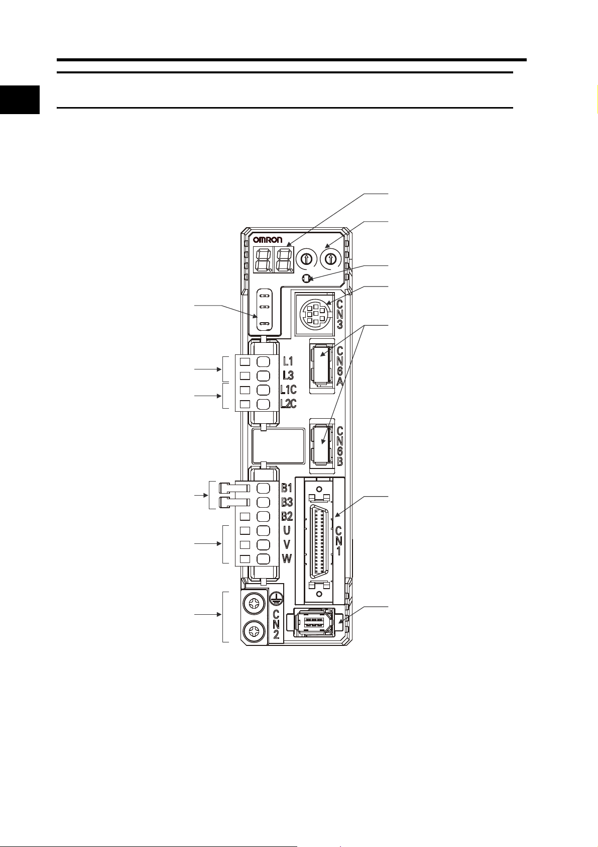
1-3 Names of Parts and Functions
Servo Drive Part Names
Display area
Rotary switches
AC SERVO DRIVE
ADR
0
0
1
1
9
2
Analog monitor check pins
(
SP, IM, G
Main-circuit power terminals
(L1, L2, L3)
Control-circuit power terminals
(L1C, L2C)
2
8
3
3
7
4
6
5
X10
COM
SP
)
IM
G
X1
MECHATROLINK-II
communications
status LED indicator
RS-232
communications connector
CN3
)
(
MECHATROLINK-II
communications connector
(
CN6A, CN6B
)
External Regeneration Resistor
connection terminals
(B1, B2, B3)
Servomotor connection terminals
(U, V, W)
Protective ground terminals
Control I/O connector (CN1)
Encoder connector (CN2)
1-3
Page 25

Servo Drive Functions
Display Area
A 2-digit 7-segment LED display shows the Servo Drive status, alarm codes, parameters, and other
information.
Analog Monitor Check Pins (SP, IM, and G)
The actual motor speed, command speed, torque, and number of accumulated pulses can be
measured based on the analog voltage level by using an oscilloscope.
Set the type of signal to be output and the output voltage level by setting the Speed Monitor (SP)
Selection (Pn007) and Torque Monitor (IM) Selection (Pn008).
For details, refer to User Parameters on page 5-55.
MECHATROLINK-II Status LED Indicator
Indicates the communications status of the MECHATROLINK-II.
For details, refer to MECHATROLINK-II Status LED Indicator on page 6-4.
1-3 Names of Parts and Functions
1
Rotary Switches
Sets the node address.
For details, refer to Servo Drive Display and Settings on page 6-3.
Features and System Configuration
1-4
Page 26

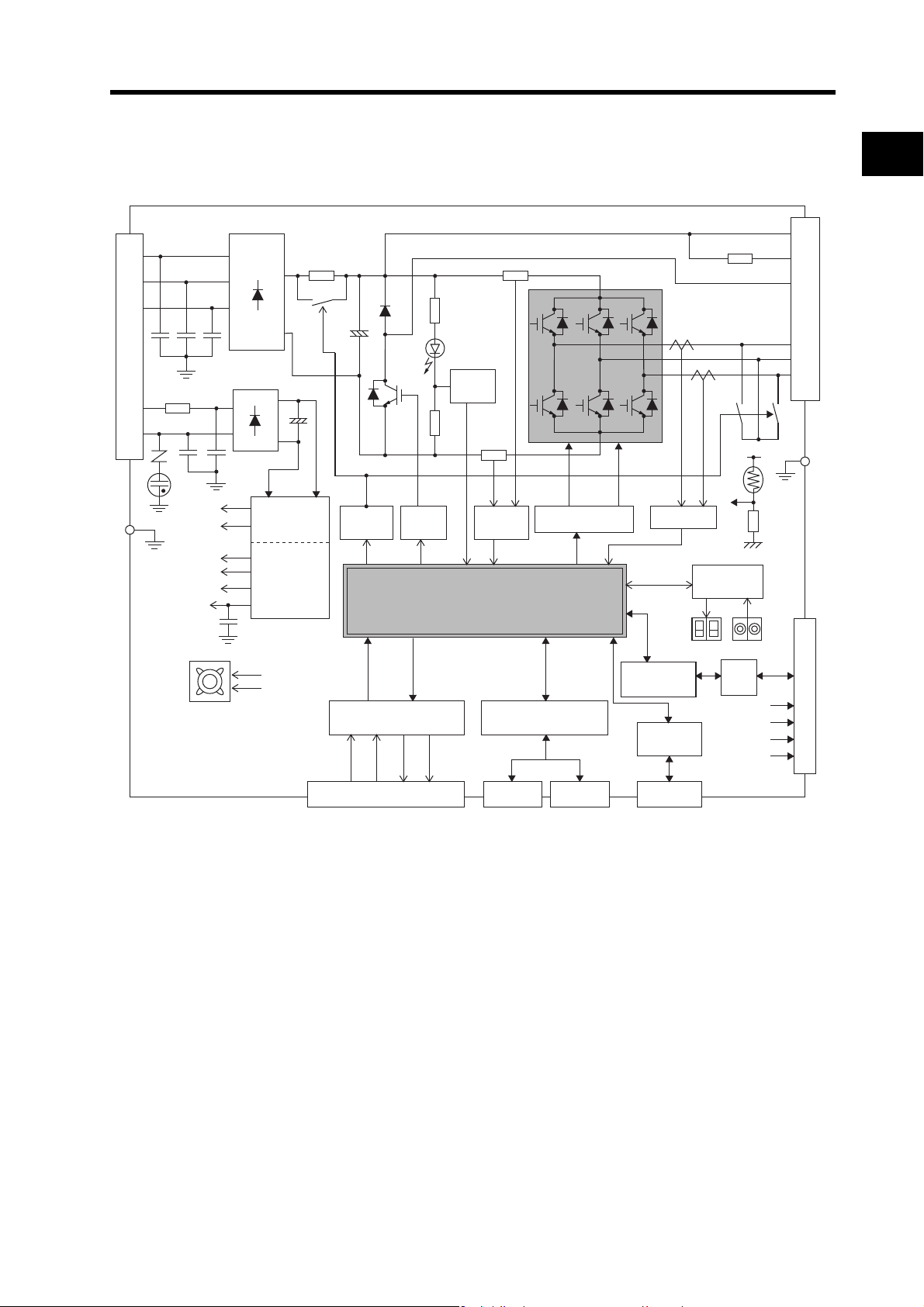
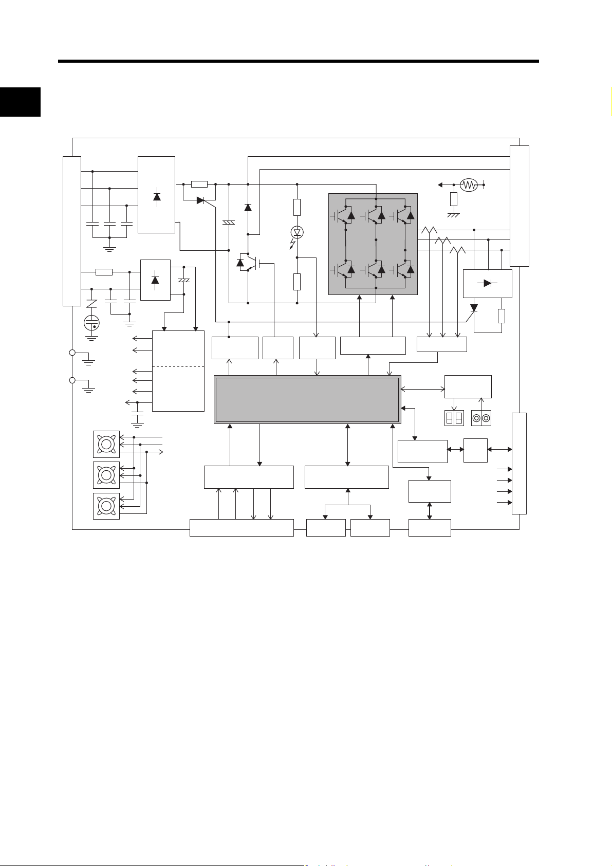
1-4 System Block Diagrams
GR
Control I/O interface
MECHATROLINK-II
interface
MECHATROLINK-II
communications line
RS-232
computer
Display/
setting circuits
Gate drive
SW power
supply
Main circuit
control
Internal
control
power
supply
RS-232
interface
CN6B
connector
CN6A
connector
CN3
connector
CN2 encoder signal connector
GR
L2C
L1C
L2
L3
L1
FUSE
CN A
+
−
~
+
−
~
~
~
15V
G1
VCC1
±VCC
G2
E5V
Overcurrent
detection
Current
detection
Voltage
detection
Regenerative
control
Relay
drive
TH
GR
CN1 control I/O connector
RS
485
±S
+
E5V
+
BAT
EG
G
B1
B2
CN B
OH
U
V
W
MPU & ASIC
Position, speed, and torque processor,
PWM control
Encoder
communications
interface
1
Features and System Configuration
1-4 System Block Diagrams
R88D-GNA5L-ML2/-GN01L-ML2/-GN02L-ML2/-GN01H-ML2/
-GN02H-ML2/-GN04H-ML2
1-5
Page 27
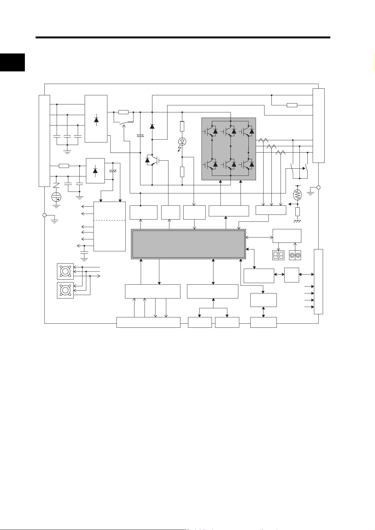
1-4 System Block Diagrams
Gate drive
SW power
supply
Main circuit
control
Internal
control
power
supply
GR
L2C
L1C
L2
L3
L1
FUSE
CN A
+
−
~
~
+
−
~
~
~
15V
G1
VCC1
±VCC
G2
E5V
Overcurrent
detection
Current
detection
Voltage
detection
Regenerative
control
Relay
drive
TH
GR
CN B
U
V
W
B1
B3
B2
Internal regeneration resistor
Cooling fan
Control I/O interface
MECHATROLINK-II
interface
Display/
setting circuits
RS-232
interface
CN6B
connector
CN6A
connector
CN3
connector
CN2 encoder signal connector
CN1 control I/O connector
RS
485
±S
+
E5V
+
BAT
EG
G
MPU & ASIC
Position, speed, and torque processor,
PWM control
Encoder
communications
interface
MECHATROLINK-II
communications line
RS-232
computer
R88D-GN04L-ML2/-GN08H-ML2/-GN10H-ML2/-GN15H-ML2
1
Features and System Configuration
1-6
Page 28
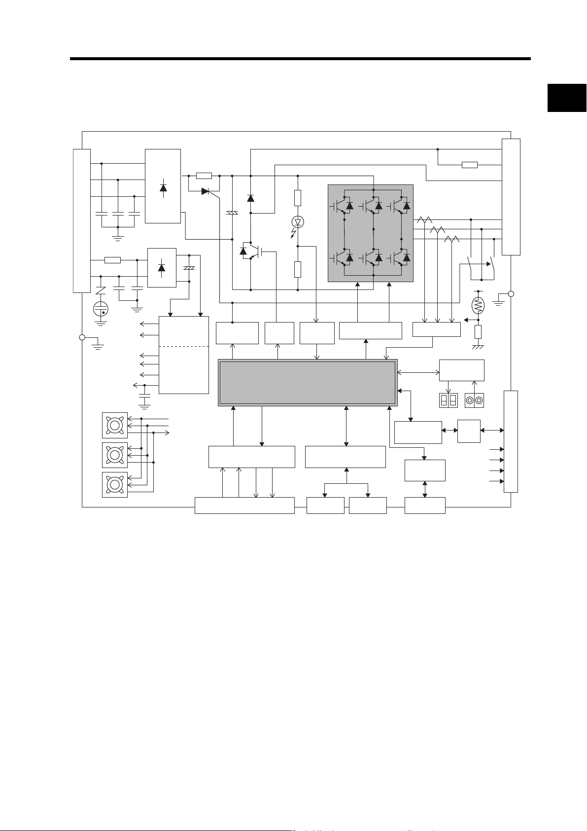
1-4 System Block Diagrams
GR
Gate drive
SW power
supply
Main circuit
control
Internal
control
power
supply
L2C
L1C
L2
L3
L1
FUSE
+
−
~
+
−
~
~
~
15V
G1
VCC1
±VCC
G2
E5V
Voltage
detection
Current
detection
Regenerative
control
Relay
drive
TH
GR
TerminalsTerminals
U
V
W
Cooling fan
B1
B3
B2
Internal regeneration resistor
Control I/O interface
MECHATROLINK-II
interface
RS-232
interface
CN6B
connector
CN6A
connector
CN3
connector
CN2 encoder signal connector
CN1 control I/O connector
RS
485
±S
+
E5V
+
BAT
EG
G
MPU & ASIC
Position, speed, and torque processor,
PWM control
Encoder
communications
interface
Display/
setting circuits
~
MECHATROLINK-II
communications line
RS-232
computer
1
R88D-GN20H-ML2
Features and System Configuration
1-7
Page 29
R88D-GN30H-ML2/GN50H-ML2
GR
Gate drive
SW power
supply
Main circuit
control
Internal
control
power
supply
L2C
L1C
L2
L3
L1
FUSE
+
−
~
~
+
−
~
~
~
15V
G1
VCC1
±VCC
G2
E5V
Voltage
detection
Current
detection
Regenerative
control
Relay,Gate
drive
TH
GR
TerminalsTerminals
U
V
W
Cooling fan
B1
B3
B2
Internal regeneration resistor
Control I/O interface
MECHATROLINK-II
interface
Display/
setting circuits
RS-232
interface
CN6B
connector
CN6A
connector
CN3
connector
CN2 encoder signal connector
CN1 control I/O connector
RS
485
±S
+
E5V
+
BAT
EG
G
MPU & ASIC
Position, speed, and torque processor,
PWM control
Encoder
communications
interface
MECHATROLINK-II
communications line
RS-232
computer
1-4 System Block Diagrams
1
Features and System Configuration
1-8
Page 30
1-4 System Block Diagrams
GR
TH
Gate drive
SW power
supply
Main circuit
control
Internal
control
power
supply
L2C
L1C
L2
L3
L1
FUSE
+
−
~
~
+
+
−
−
~
~
~
15V
G1
VCC1
±VCC
G2
E5V
Voltage
detection
Current
detection
Regenerative
control
Relay,Gate
drive
B1
B2
TerminalsTerminals
U
V
W
Cooling fan
~~~
Control I/O interface
MECHATROLINK-II
interface
Display/
setting circuits
RS-232
interface
CN6B
connector
CN6A
connector
CN3
connector
CN2 encoder signal connector
CN1 control I/O connector
RS
485
±S
+
E5V
+
BAT
EG
G
MPU & ASIC
Position, speed, and torque processor,
PWM control
Encoder
communications
interface
MECHATROLINK-II
communications line
RS-232
computer
1
R88D-GN75H-ML2
Features and System Configuration
1-9
Page 31
1-5 Applicable Standards
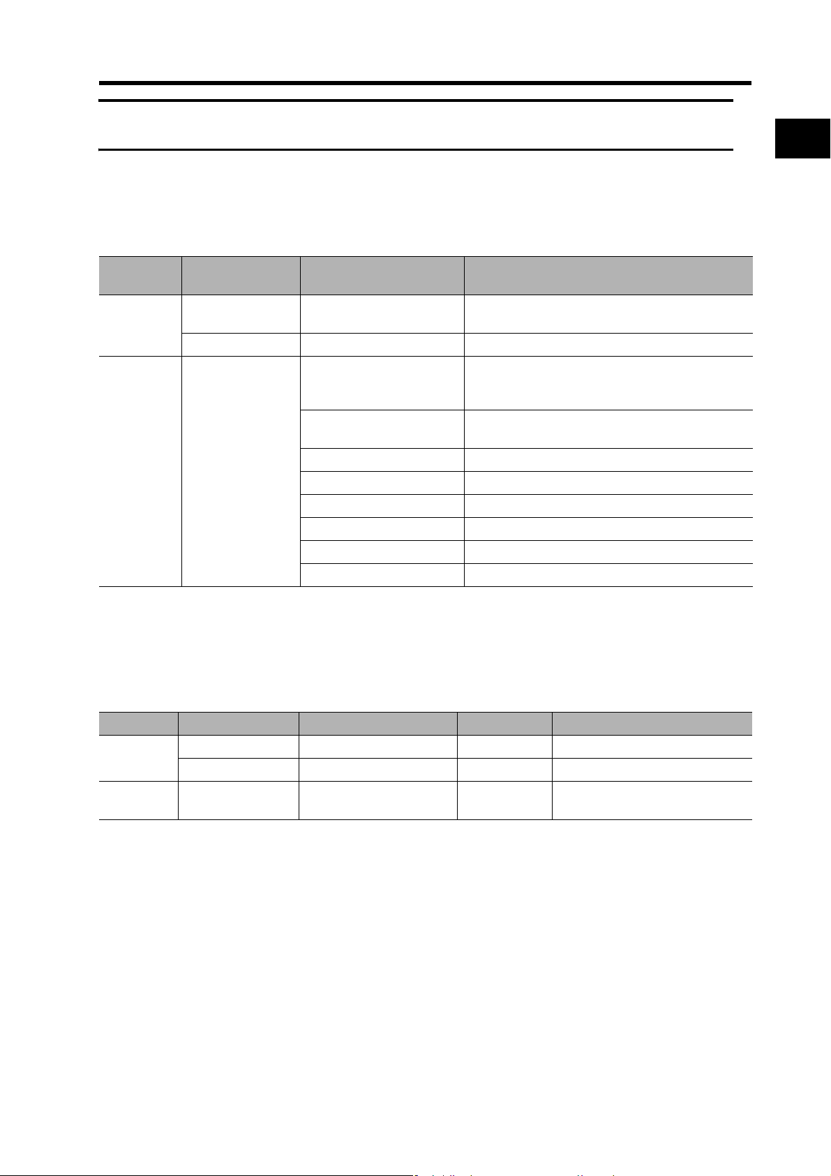
1-5 Applicable Standards
EC Directives
EC Direc-
tives
Low Voltage
Directive
EMC
Directive
Product Applicable standards Comments
AC Servo Drive EN 50178
AC Servomotors IEC 60034-1/-5 Rotating electrical machines
EN 55011 Class A Group 1
EN 61000-6-2
AC Servo Drive
AC Servomotors
IEC 61000-4-2 Electrostatic discharge immunity testing
IEC 61000-4-3 Radio frequency radiation field immunity testing
IEC 61000-4-4 Electrical fast transient burst immunity testing
IEC 61000-4-5 Lightning surge immunity testing
IEC 61000-4-6 High-frequency conduction immunity testing
IEC 61000-4-11 Momentary power interruption immunity testing
Safety requirements for electrical equipment for
measurement, control, or laboratory use
Limits of radio disturbance and measurement
methods for industrial, scientific, and medical
radio-frequency equipment
Electromagnetic compatibility (EMC) Immunity
standard for industrial environments
1
Features and System Configuration
Note To conform to the EMC Directives, the Servomotor and Servo Drive must be installed under
the conditions described in Wiring Conforming to EMC Directives on page 4-26.
UL and CSA Standards
Standard Product Applicable standards File number Comments
UL
standards
CSA
standards
*1. UL approval is pending for motor capacities of 6 to 7.5 kW.
AC Servo Drive UL 508C E179149 Power conversion equipment
AC Servomotors
AC Servomotors
*1
UL 1004 E179189 Electric motor
*1
CSA22.2 No.100 E179189 Motor and generator
1-10
Page 32

Page 33

Chapter 2
Standard Models and Dimensions
2-1 Standard Models................................................2-1
Servo Drives .........................................................................2-1
Servomotors..........................................................................2-2
Servo Drive-Servomotor Combinations ................................2-5
Decelerators..........................................................................2-7
Accessories and Cables .......................................................2-14
2-2 External and Mounting Hole Dimensions...........2-23
Servo Drives .........................................................................2-23
Servomotors..........................................................................2-33
Parameter Unit Dimensions..................................................2-43
Servomotor and Decelerator Combinations..........................2-44
Decelerator Dimensions........................................................2-47
External Regeneration Resistor Dimensions........................2-61
Reactor Dimensions..............................................................2-62
Page 34

2-1 Standard Models
2-1 Standard Models
2
Servo Drives
Single-phase 100 VAC
Single-phase 200 VAC
Single-phase/three-phase 200 VAC
Standard Models and Dimensions
Three-phase 200 VAC
Specifications Model
50 W R88D-GNA5L-ML2
100 W R88D-GN01L-ML2
200 W R88D-GN02L-ML2
400 W R88D-GN04L-ML2
50 W
R88D-GN01H-ML2
100 W
200 W R88D-GN02H-ML2
400 W R88D-GN04H-ML2
750 W R88D-GN08H-ML2
1 kW R88D-GN10H-ML2
900 W
R88D-GN15H-ML21 kW
1.5 kW
2 kW R88D-GN20H-ML2
2 kW
R88D-GN30H-ML2
3 kW
3 kW
4 kW
R88D-GN50H-ML2
4.5 kW
5 kW
6 kW
R88D-GN75H-ML2
7.5 kW
2-1
Page 35

Servomotors
3,000-r/min Servomotors
Specifications
50 W R88M-G05030H R88M-G05030H-S2 R88M-G05030T R88M-G05030T-S2
100 W R88M-G10030L R88M-G10030L-S2 R88M-G10030S R88M-G10030S-S2
100 V
200 W R88M-G20030L R88M-G20030L-S2 R88M-G20030S R88M-G20030S-S2
400 W R88M-G40030L R88M-G40030L-S2 R88M-G40030S R88M-G40030S-S2
50 W R88M-G05030H R88M-G05300H-S2 R88M-G05030T R88M-G05030T-S2
100 W R88M-G10030H R88M-G10030H-S2 R88M-G10030T R88M-G10030T-S2
200
With-
out
brake
200 V
100 V
With
brake
200 V
W R88M-G20030H R88M-G20030H-S2 R88M-G20030T R88M-G20030T-S2
400 W R88M-G40030H R88M-G40030H-S2 R88M-G40030T R88M-G40030T-S2
750 W R88M-G75030H R88M-G75030H-S2 R88M-G75030T R88M-G75030T-S2
1 kW --- --- R88M-G1K030T R88M-G1K030T-S2
1.5kW --- --- R88M-G1K530T R88M-G1K530T-S2
2 kW --- --- R88M-G2K030T R88M-G2K030T-S2
3 kW --- --- R88M-G3K030T R88M-G3K030T-S2
4 kW --- --- R88M5 kW --- --- R88M-G5K030T R88M-G5K030T-S2
50 W R88M-G05030H-B
100 W R88M-G10030L-B
200 W R88M-G20030L-B
400 W R88M-G40030L-B
50 W R88M-G05030H-B
100 W R88M-G10030H-B
200 W R88M-G20030H-B
400 W R88M-G40030H-B
750 W R88M-G75030H-B
1 kW --- --- R88M-G1K030T-B
1.5kW --- --- R88M-G1K530T-B
2 kW --- --- R88M-G2K030T-B
3 kW --- --- R88M-G3K030T-B
4 kW --- --- R88M-G4K030T-B
5 kW --- --- R88M-G5K030T-B
Note Models with oil seals are also available.
With incremental encoder With absolute encoder
Straight shaft
without key
R88M-G05030H-BS2
R88M-G10030L-BS2
R88M-G20030L-BS2
R88M-G40030L-BS2
R88M-G05030H-BS2
R88M-G10030H-BS2
R88M-G20030H-BS2
R88M-G40030H-BS2
R88M-G75030H-BS2
Straight shaft
with key and tap
Model
Straight shaft
without key
G4K030T
R88M-G05030T-B
R88M-G10030S-B
R88M-G20030S-B
R88M-G40030S-B
R88M-G05030T-B
R88M-G10030T-B
R88M-G20030T-B
R88M-G40030T-B
R88M-G75030T-B
2-1 Standard Models
Straight shaft
with key and tap
R88M-G4K030T-S2
R88M-G05030T-BS2
R88M-G10030S-BS2
R88M-G20030S-BS2
R88M-G40030S-BS2
R88M-G05030T-BS2
R88M-G10030T-BS2
R88M-G20030T-BS2
R88M-G40030T-BS2
R88M-G75030T-BS2
R88M-G1K030T-BS2
R88M-G1K530T-BS2
R88M-G2K030T-BS2
R88M-G3K030T-BS2
R88M-G4K030T-BS2
R88M-G5K030T-BS2
2
Standard Models and Dimensions
2-2
Page 36

2-1 Standard Models
3,000-r/min Flat Servomotors
Model
Specifications
2
100 W R88M-GP10030L
100 V
With-
out
brake
With
brake
Note Models with oil seals are also available.
200 W R88M-GP20030L
400 W R88M-GP40030L
100 W R88M-GP10030H
200 V
200 W R88M-GP20030H
400 W R88M-GP40030H
100 W R88M-GP10030L-B
200 W R88M-GP20030L-B
100 V
400 W R88M-GP40030L-B
100 W R88M-GP10030H-B
200 V
200 W R88M-GP20030H-B
400 W R88M-GP40030H-B
With incremental encoder With absolute encoder
Straight shaft
without key
Straight shaft
with key and tap
R88M-GP10030L-S2
R88M-GP20030L-S2
R88M-GP40030L-S2
R88M-GP10030H-S2
R88M-GP20030H-S2
R88M-GP40030H-S2
R88M-GP10030L-BS2
R88M-GP20030L-BS2
R88M-GP40030L-BS2
R88M-GP10030H-BS2
R88M-GP20030H-BS2
R88M-GP40030H-BS2
Straight shaft
without key
R88M-GP10030S
R88M-GP20030S
R88M-GP40030S
R88M-GP10030T
R88M-GP20030T
R88M-GP40030T
R88M-GP10030S-B
R88M-GP20030S-B
R88M-GP40030S-B
R88M-GP10030T-B
R88M-GP20030T-B
R88M-GP40030T-B
Straight shaft
with key and tap
R88M-GP10030S-S2
R88M-GP20030S-S2
R88M-GP40030S-S2
R88M-GP10030T-S2
R88M-GP20030T-S2
R88M-GP40030T-S2
R88M-GP10030S-BS2
R88M-GP20030S-BS2
R88M-GP40030S-BS2
R88M-GP10030T-BS2
R88M-GP20030T-BS2
R88M-GP40030T-BS2
2,000-r/min Servomotors
Model
Specifications
Standard Models and Dimensions
With-
out
200 V
brake
With
200 V
brake
1 kW R88M-G1K020T R88M-G1K020T-S2
1.5 kW R88M-G1K520T R88M-G1K520T-S2
2 kW R88M-G2K020T R88M-G2K020T-S2
3 kW R88M-G3K020T R88M-G3K020T-S2
4 kW R88M-G4K020T R88M-G4K020T-S2
5 kW R88M-G5K020T R88M-G5K020T-S2
7.5 kW R88M-G7K515T R88M-G7K515T-S2
1 kW R88M-G1K020T-B R88M-G1K020T-BS2
1.5 kW R88M-G1K520T-B R88M-G1K520T-BS2
2 kW R88M-G2K020T-B R88M-G2K020T-BS2
3 kW R88M-G3K020T-B R88M-G3K020T-BS2
4 kW R88M-G4K020T-B R88M-G4K020T-BS2
5 kW R88M-G5K020T-B R88M-G5K020T-BS2
7.5 kW R88M-G7K515T-B R88M-G7K515T-BS2
Straight shaft
without key
Note1. Models with oil seals are also available.
Note2. The rated rotation speed for 7.5-kW Servomotors is 1,500 r/min.
With absolute encoder
Straight shaft
with key and tap
2-3
Page 37

1,000-r/min Servomotors
Model
Specifications
900 W R88M-G90010T R88M-G90010T-S2
With-
out
brake
With
brake
Note Models with oil seals are also available.
2 kW R88M-G2K010T R88M-G2K010T-S2
200 V
3 kW R88M-G3K010T R88M-G3K010T-S2
4.5 kW R88M-G4K510T R88M-G4K510T-S2
6 kW R88M-G6K010T R88M-G6K010T-S2
900 W R88M-G90010T-B R88M-G90010T-BS2
2 kW R88M-G2K010T-B R88M-G2K010T-BS2
200 V
3 kW R88M-G3K010T-B R88M-G3K010T-BS2
4.5 kW R88M-G4K510T-B R88M-G4K510T-BS2
6 kW R88M-G6K010T-B R88M-G6K010T-BS2
Straight shaft
without key
With absolute encoder
Straight shaft
with key and tap
2-1 Standard Models
2
Standard Models and Dimensions
2-4
Page 38

2-1 Standard Models
Servo Drive-Servomotor Combinations
2
The tables in this section show the possible combinations of OMNUC G-Series Servo Drives and
Servomotors. The Servomotors and Servo Drives can only be used in the listed combinations.
The box (-@) at the end of the model number is for options, such as the shaft type, brake and
Decelerators.
3,000-r/min Servomotors and Servo Drives
Voltage
100 V
Single-
phase 200 V
Singlephase/threephase 200 V
Standard Models and Dimensions
Three-phase
200 V
Rated
output
50 W R88M-G05030H-@ R88M-G05030T-@ R88D-GNA5L-ML2
100 W R88M-G10030L-
200 W R88M-G20030L-
400 W R88M-G40030L-
50 W R88M-G05030H-
100 W R88M-G10030H-
200 W R88M-G20030H-
400 W R88M-G40030H-
750 W R88M-G75030H-
1 kW --- R88M-G1K030T-
1.5 kW --- R88M-G1K530T-
2 kW --- R88M-G2K030T-
3 kW --- R88M-G3K030T4 kW --- R88M-G4K030T-
5 kW --- R88M-G5K030T-
With incremental encoder With absolute encoder
Servomotor
Servo Drive
@ R88M-G10030S-@ R88D-GN01L-ML2
@ R88M-G20030S-@ R88D-GN02L-ML2
@ R88M-G40030S-@ R88D-GN04L-ML2
@ R88M-G05030T-@ R88D-GN01H-ML2
@ R88M-G10030T-@ R88D-GN01H-ML2
@ R88M-G20030T-@ R88D-GN02H-ML2
@ R88M-G40030T-@ R88D-GN04H-ML2
@ R88M-G75030T-@ R88D-GN08H-ML2
@ R88D-GN15H-ML2
@ R88D-GN15H-ML2
@ R88D-GN20H-ML2
@ R88D-GN30H-ML2
@ R88D-GN50H-ML2
@ R88D-GN50H-ML2
3,000-r/min Flat Servomotors and Servo Drives
Servomotor
Voltage
100 V
Single-
phase 200 V
Rated
output
100 W R88M-GP10030L-@ R88M-GP10030S-@ R88D-GN01L-ML2
200 W R88M-GP20030L-
400 W R88M-GP40030L-
100 W R88M-GP10030H-
200 W R88M-GP20030H-
400 W R88M-GP40030H-
With incremental encoder With absolute encoder
@ R88M-GP20030S-@ R88D-GN02L-ML2
@ R88M-GP40030S-@ R88D-GN04L-ML2
@ R88M-GP10030T-@ R88D-GN01H-ML2
@ R88M-GP20030T-@ R88D-GN02H-ML2
@ R88M-GP40030T-@ R88D-GN04H-ML2
Servo Drive
2-5
Page 39

2,000-r/min Servomotors and Servo Drives
Servomotor
Voltage
Singlephase/threephase 200 V
Three-phase
200 V
Rated
output
1 kW R88M-G1K020T-@ R88D-GN10H-ML2
1.5 kW R88M-G1K520T-@ R88D-GN15H-ML2
2 kW R88M-G2K020T-
3 kW R88M-G3K020T4 kW R88M-G4K020T-
5 kW R88M-G5K020T-
7.5 kW R88M-G7K515T-
With absolute encoder
@ R88D-GN20H-ML2
@ R88D-GN30H-ML2
@ R88D-GN50H-ML2
@ R88D-GN50H-ML2
@ R88D-GN75H-ML2
1,000-r/min Servomotors and Servo Drives
Servomotor
Voltage
Singlephase/threephase 200 V
Three-phase
200 V
Rated
output
900 W R88M-G90010T-@ R88D-GN15H-ML2
2 kW R88M-G2K010T-
3 kW R88M-G3K010T-
4.5 kW R88M-G4K510T-
6 kW R88M-G6K010T-
With absolute encoder
@ R88D-GN30H-ML2
@ R88D-GN50H-ML2
@ R88D-GN50H-ML2
@ R88D-GN75H-ML2
2-1 Standard Models
Servo Drive
2
Servo Drive
Standard Models and Dimensions
2-6
Page 40

2-1 Standard Models
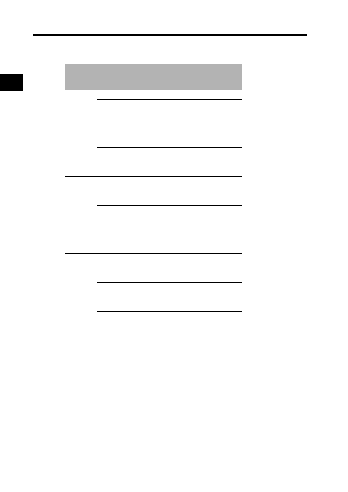
Decelerators
The following types of Decelerators are available for OMNUC G-Series Servomotors. Select a
2
Backlash = 3’ Max.
Standard Models and Dimensions
Decelerator based on the Servomotor capacity.
Decelerators for 3,000-r/min Servomotors
Specifications
Motor
capacity
50 W
100 W
200 W
400 W
750 W
Gear ratio
1/5 R88G-HPG11A05100B
1/9 R88G-HPG11A09050B@
1/21 R88G-HPG14A21100B@
1/33 R88G-HPG14A33050B@
1/45 R88G-HPG14A45050B@
1/5 R88G-HPG11A05100B
1/11 R88G-HPG14A11100B@
1/21 R88G-HPG14A21100B@
1/33 R88G-HPG20A33100B@
1/45 R88G-HPG20A45100B@
1/5 R88G-HPG14A05200B
1/11 R88G-HPG14A11200B@
1/21 R88G-HPG20A21200B@
1/33 R88G-HPG20A33200B@
1/45 R88G-HPG20A45200B@
1/5 R88G-HPG14A05400B
1/11 R88G-HPG20A11400B@
1/21 R88G-HPG20A21400B@
1/33 R88G-HPG32A33400B@
1/45 R88G-HPG32A45400B@
1/5 R88G-HPG20A05750B
1/11 R88G-HPG20A11750B@
1/21 R88G-HPG32A21750B@
1/33 R88G-HPG32A33750B@
1/45 R88G-HPG32A45750B@
Model
@
@
@
@
@
2-7
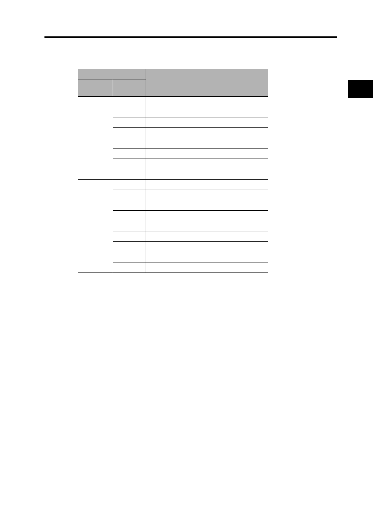
Page 41

Specifications
Motor
capacity
1 kW
1.5 kW
2 kW
3 kW
4 kW
5 kW
Gear ratio
Model
1/5 R88G-HPG32A051K0B
1/11 R88G-HPG32A111K0B@
1/21 R88G-HPG32A211K0B@
1/33 R88G-HPG32A331K0B@
1/45 R88G-HPG50A451K0B@
1/5 R88G-HPG32A052K0B
1/11 R88G-HPG32A112K0B@
1/21 R88G-HPG32A211K5B@
1/33 R88G-HPG50A332K0B@
1/45 R88G-HPG50A451K5B@
1/5 R88G-HPG32A052K0B
1/11 R88G-HPG32A112K0B@
1/21 R88G-HPG50A212K0B@
1/33 R88G-HPG50A332K0B@
1/5 R88G-HPG32A053K0B
1/11 R88G-HPG50A113K0B@
1/21 R88G-HPG50A213K0B@
1/5 R88G-HPG32A054K0B
1/11 R88G-HPG50A115K0B@
1/5 R88G-HPG50A055K0B
1/11 R88G-HPG50A115K0B@
2-1 Standard Models
@
@
@
@
2
Standard Models and Dimensions
@
@
Note1. The standard models have a straight shaft.
Note2. Models with a key and tap are indicated with "J" at the end of the model number (the suffix
shown in the box). (Example: R88G-HPG11A05100BJ)
2-8
Page 42
2-1 Standard Models
Decelerators for 2,000-r/min Servomotors
Specifications
2
Standard Models and Dimensions
Motor
capacity
1 kW
1.5 kW
2 kW
3 kW
4 kW
5 kW
7.5 kW
Gear ratio
1/5 R88G-HPG32A053K0B@
1/11 R88G-HPG32A112K0SB@
1/21 R88G-HPG32A211K0SB@
1/33 R88G-HPG50A332K0SB@
1/45 R88G-HPG50A451K0SB@
1/5 R88G-HPG32A053K0B
1/11 R88G-HPG32A112K0SB@
1/21 R88G-HPG50A213K0B@
1/33 R88G-HPG50A332K0SB@
1/5 R88G-HPG32A053K0B
1/11 R88G-HPG32A112K0SB@
1/21 R88G-HPG50A213K0B@
1/33 R88G-HPG50A332K0SB@
1/5 R88G-HPG32A054K0B
1/11 R88G-HPG50A115K0B@
1/21 R88G-HPG50A213K0SB@
1/25 R88G-HPG65A253K0SB@
1/5 R88G-HPG50A054K0SB
1/11 R88G-HPG50A114K0SB@
1/20 R88G-HPG65A204K0SB@
1/25 R88G-HPG65A254K0SB@
1/5 R88G-HPG50A055K0SB
1/11 R88G-HPG50A115K0SB@
1/20 R88G-HPG65A205K0SB@
1/25 R88G-HPG65A255K0SB@
1/5 R88G-HPG65A057K5SB
1/12 R88G-HPG65A127K5SB@
Model
@
@
@
@
@
@
2-9
Note1. The standard models have a straight shaft.
Note2. Models with a key and tap are indicated with "J" at the end of the model number
(the suffix shown in the box). (Example: R88G-HPG32A053K0BJ)
Page 43
Decelerators for 1,000-r/min Servomotors
Specifications
Motor
capacity
900 W
2 kW
3 kW
4.5 kW
6 kW
Gear ratio
1/5 R88G-HPG32A05900TB@
1/11 R88G-HPG32A11900TB@
1/21 R88G-HPG50A21900TB@
1/33 R88G-HPG50A33900TB@
1/5 R88G-HPG32A052K0TB
1/11 R88G-HPG50A112K0TB@
1/21 R88G-HPG50A212K0TB@
1/25 R88G-HPG65A255K0SB@
1/5 R88G-HPG50A055K0SB
1/11 R88G-HPG50A115K0SB@
1/20 R88G-HPG65A205K0SB@
1/25 R88G-HPG65A255K0SB@
1/5 R88G-HPG50A054K5TB
1/12 R88G-HPG65A127K5SB@
1/20 R88G-HPG65A204K5TB@
1/5 R88G-HPG65A057K5SB
1/12 R88G-HPG65A127K5SB@
Model
2-1 Standard Models
2
@
@
@
@
Standard Models and Dimensions
Note1. The standard models have a straight shaft.
Note2. Models with a key and tap are indicated with "J" at the end of the model number
(the suffix shown in the box). (Example: R88G-HPG32A05900TBJ)
2-10
Page 44

2-1 Standard Models
Decelerators for 3,000-r/min Flat Servomotors
Specifications
2
Motor
capacity
100 W
200 W
400 W
Gear ratio
1/5 R88G-HPG11A05100PB@
1/11 R88G-HPG14A11100PB@
1/21 R88G-HPG14A21100PB@
1/33 R88G-HPG20A33100PB@
1/45 R88G-HPG20A45100PB@
1/5 R88G-HPG14A05200PB
1/11 R88G-HPG20A11200PB@
1/21 R88G-HPG20A21200PB@
1/33 R88G-HPG20A33200PB@
1/45 R88G-HPG20A45200PB@
1/5 R88G-HPG20A05400PB
1/11 R88G-HPG20A11400PB@
1/21 R88G-HPG20A21400PB@
1/33 R88G-HPG32A33400PB@
1/45 R88G-HPG32A45400PB@
Standard Models and Dimensions
Note1. The standard models have a straight shaft.
Note2. Models with a key and tap are indicated with "J" at the end of the model number
(the suffix shown in the box). (Example: R88G-HPG11A05100PBJ)
Model
@
@
2-11
Page 45

Backlash = 15’ Max.
Decelerators for 3,000-r/min Servomotors (Straight Shaft with Key)
2-1 Standard Models
Specifications
Motor
capacity
50 W
100 W
200 W
400 W
750 W
Gear ratio
1/5 R88G-VRSF05B100CJ
1/9 R88G-VRSF09B100CJ
1/15 R88G-VRSF15B100CJ
1/25 R88G-VRSF25B100CJ
1/5 R88G-VRSF05B100CJ
1/9 R88G-VRSF09B100CJ
1/15 R88G-VRSF15B100CJ
1/25 R88G-VRSF25B100CJ
1/5 R88G-VRSF05B200CJ
1/9 R88G-VRSF09C200CJ
1/15 R88G-VRSF15C200CJ
1/25 R88G-VRSF25C200CJ
1/5 R88G-VRSF05C400CJ
1/9 R88G-VRSF09C400CJ
1/15 R88G-VRSF15C400CJ
1/25 R88G-VRSF25C400CJ
1/5 R88G-VRSF05C750CJ
1/9 R88G-VRSF09D750CJ
1/15 R88G-VRSF15D750CJ
1/25 R88G-VRSF25D750CJ
2
Model
Standard Models and Dimensions
2-12
Page 46
2-1 Standard Models
Decelerators for 3,000-r/min Flat Servomotors (Straight Shaft with Key)
Specifications
2
Motor
capacity
100 W
200 W
400 W
Gear ratio
1/5 R88G-VRSF05B100PCJ
1/9 R88G-VRSF09B100PCJ
1/15 R88G-VRSF15B100PCJ
1/25 R88G-VRSF25B100PCJ
1/5 R88G-VRSF05B200PCJ
1/9 R88G-VRSF09C200PCJ
1/15 R88G-VRSF15C200PCJ
1/25 R88G-VRSF25C200PCJ
1/5 R88G-VRSF05C400PCJ
1/9 R88G-VRSF09C400PCJ
1/15 R88G-VRSF15C400PCJ
1/25 R88G-VRSF25C400PCJ
Model
Standard Models and Dimensions
2-13
Page 47
Accessories and Cables
2-1 Standard Models
Encoder Cables (Standard Cables)
Specifications Model
3,000-r/min Servomotors of 50 to 750 W
with an absolute encoder,
3,000-r/min Flat Servomotors of 100 to 400 W
with an absolute encoder
3,000-r/min Servomotors of 50 to 750 W
with an incremental encoder,
3,000-r/min Flat Servomotors of 100 to 400 W
with an incremental encoder
3,000-r/min Servomotors of 1 to 5 kW,
2,000-r/min Servomotors of 1 to 5 kW,
1,500-r/min Servomotors of 7.5 kW,
1,000-r/min Servomotors of 900 W to 6 kW
3 mR88A-CRGA003C
5 m R88A-CRGA005C
10 m R88A-CRGA010C
15 m R88A-CRGA015C
20 m R88A-CRGA020C
30 m R88A-CRGA030C
40 m R88A-CRGA040C
50 m R88A-CRGA050C
3 mR88A-CRGB003C
5 m R88A-CRGB005C
10 m R88A-CRGB010C
15 m R88A-CRGB015C
20 m R88A-CRGB020C
30 m R88A-CRGB030C
40 m R88A-CRGB040C
50 m R88A-CRGB050C
3 mR88A-CRGC003N
5 m R88A-CRGC005N
10 m R88A-CRGC010N
15 m R88A-CRGC015N
20 m R88A-CRGC020N
30 m R88A-CRGC030N
40
50 m R88A-CRGC050N
R88A-CRGC040N
m
2
Standard Models and Dimensions
2-14
Page 48

2-1 Standard Models
Servomotor Power Cables (Standard Cables)
Specifications
2
3,000-r/min Servomotors of 50 to 750 W,
3,000-r/min Flat Servomotors of
100 to 400 W
3,000-r/min Servomotors of 1 to 1.5 kW,
2,000-r/min Servomotors of 1 to 1.5 kW,
1,000-r/min Servomotors of 900 W
Standard Models and Dimensions
3,000-r/min Servomotors of 2 kW,
2,000-r/min Servomotors of 2 kW
3,000-r/min Servomotors of 3 to 5 kW,
2,000-r/min Servomotors of 3 to 5 kW,
1,000-r/min Servomotors of 2 to 4.5 kW
Model
For Servomotor without
brake
3 mR88A-CAGA003S ---
5 m R88A-CAGA005S ---
10 m R88A-CAGA010S ---
15 m R88A-CAGA015S ---
20 m R88A-CAGA020S ---
30 m R88A-CAGA030S --40 m R88A-CAGA040S ---
50 m R88A-CAGA050S ---
3 mR88A-CAGB003SR88A-CAGB003B
5 m R88A-CAGB005S R88A-CAGB005B
10 m R88A-CAGB010S R88A-CAGB010B
15 m R88A-CAGB015S R88A-CAGB015B
20 m R88A-CAGB020S R88A-CAGB020B
30 m R88A-CAGB030S R88A-CAGB030B
40 m R88A-CAGB040S R88A-CAGB040B
50 m R88A-CAGB050S R88A-CAGB050B
3 mR88A-CAGC003SR88A-CAGC003B
A-CAGC005S R88A-CAGC005B
R88
5 m
10 m R88A-CAGC010S R88A-CAGC010B
15 m R88A-CAGC015S R88A-CAGC015B
20 m R88A-CAGC020S R88A-CAGC020B
30 m R88A-CAGC030S R88A-CAGC030B
40 m R88A-CAGC040S R88A-CAGC040B
50 m R88A-CAGC050S R88A-CAGC050B
3 mR88A-CAGD003SR88A-CAGD003B
5 m R88A-CAGD005S R88A-CAGD005B
10 m R88A-CAGD010S R88A-CAGD010B
15 m R88A-CAGD015S R88A-CAGD015B
20 m R88A-CAGD020S R88A-CAGD020B
30 m R88A-CAGD030S R88A-CAGD030B
40 m R88A-CAGD040S R88A-CAGD040B
50 m R88A-CAGD050S R88A-CAGD050B
For Servomotor with
brake
2-15
Page 49

2-1 Standard Models
Model
Specifications
10 m R88A-CAGE010S ---
1,500-r/min Servomotors of 7.5 kW,
1,000-r/min Servomotors of 6 kW
Note There are separate connectors for power and brakes for 3,000-r/min Servomotors of 50 to
750 W, Flat Servomotors, and Servomotors of 6 kW or higher.
Therefore, when a Servomotor with a brake is used, it will require both a Power Cable for a
Servomotor without a brake and a Brake Cable.
15 m R88A-CAGE015S ---
20 m R88A-CAGE020S ---
30 m R88A-CAGE030S --40 m R88A-CAGE040S ---
50 m R88A-CAGE050S ---
For Servomotor without
brake
3 mR88A-CAGE003S--5 m R88A-CAGE005S ---
For Servomotor with
brake
2
Standard Models and Dimensions
2-16
Page 50

2-1 Standard Models
Brake Cables (Standard Cables)
Specifications Model
2
3,000-r/min Servomotors of 50 to 750 W,
3,000-r/min Flat Servomotors of 100 to 400 W
1,500-r/min Servomotors of 7.5 kW,
1,000-r/min Servomotors of 6 kW
3 mR88A-CAGA003B
5 m R88A-CAGA005B
10 m R88A-CAGA010B
15 m R88A-CAGA015B
20 m R88A-CAGA020B
30 m R88A-CAGA030B
40 m R88A-CAGA040B
50 m R88A-CAGA050B
3 mR88A-CAGE003B
5 m R88A-CAGE005B
10 m R88A-CAGE010B
15 m R88A-CAGE015B
20 m R88A-CAGE020B
30 m R88A-CAGE030B
40 m R88A-CAGE040B
50 m R88A-CAGE050B
Standard Models and Dimensions
2-17
Page 51

Encoder Cables (Robot Cables)
Specifications Model
3,000-r/min Servomotors of 50 to 750 W
with an absolute encoder,
3,000-r/min Flat Servomotors of 100 to 400 W
with an absolute encoder
3,000-r/min Servomotors of 50 to 750 W
with an incremental encoder,
3,000-r/min Flat Servomotors of 100 to 400 W
with an incremental encoder
3,000-r/min Servomotors of 1 to 5 kW,
2,000-r/min Servomotors of 1 to 5 kW,
1,000-r/min Servomotors of 900 W to 4.5 kW
2-1 Standard Models
3 mR88A-CRGA003CR
5 m R88A-CRGA005CR
10 m R88A-CRGA010CR
15 m R88A-CRGA015CR
20 m R88A-CRGA020CR
30 m R88A-CRGA030CR
40 m R88A-CRGA040CR
50 m R88A-CRGA050CR
3 mR88A-CRGB003CR
5 m R88A-CRGB005CR
10 m R88A-CRGB010CR
15 m R88A-CRGB015CR
20 m R88A-CRGB020CR
30 m R88A-CRGB030CR
40 m R88A-CRGB040CR
50 m R88A-CRGB050CR
3 mR88A-CRGC003NR
5 m R88A-CRGC005NR
10 m R88A-CRGC010NR
15 m R88A-CRGC015NR
20 m R88A-CRGC020NR
30 m R88A-CRGC030NR
40 m R
50
88A-CRGC040
m R88A-CRGC050NR
NR
2
Standard Models and Dimensions
2-18
Page 52

2-1 Standard Models
Servomotor Power Cables (Robot Cables)
Specifications
2
3,000-r/min Servomotors of 50 to 750 W,
3,000-r/min Flat Servomotors of
100 to 400 W
3,000-r/min Servomotors of 1 to 1.5 kW,
2,000-r/min Servomotors of 1 to 1.5 kW,
1,000-r/min Servomotors of 900 W
Standard Models and Dimensions
3,000-r/min Servomotors of 2 kW,
2,000-r/min Servomotors of 2 kW
3,000-r/min Servomotors of 3 to 5 kW,
2,000-r/min Servomotors of 3 to 5 kW,
1,000-r/min Servomotors of 2 to 4.5 kW
Model
For Servomotor without
brake
3 mR88A-CAGA003SR ---
5 m R88A-CAGA005SR ---
10 m R88A-CAGA010SR ---
15 m R88A-CAGA015SR ---
20 m R88A-CAGA020SR ---
30 m R88A-CAGA030SR --40 m R88A-CAGA040SR ---
50 m R88A-CAGA050SR ---
3 mR88A-CAGB003SR R88A-CAGB003BR
5 m R88A-CAGB005SR R88A-CAGB005BR
10 m R88A-CAGB010SR R88A-CAGB010BR
15 m R88A-CAGB015SR R88A-CAGB015BR
20 m R88A-CAGB020SR R88A-CAGB020BR
30 m R88A-CAGB030SR R88A-CAGB030BR
40 m R88A-CAGB040SR R88A-CAGB040BR
50 m R88A-CAGB050SR R88A-CAGB050BR
3 mR88A-CAGC003SR R88A-CAGC003BR
5 m
R88
A-CAGC005SR R88A-CAGC005BR
10 m R88A-CAGC010SR R88A-CAGC010BR
15 m R88A-CAGC015SR R88A-CAGC015BR
20 m R88A-CAGC020SR R88A-CAGC020BR
30 m R88A-CAGC030SR R88A-CAGC030BR
40 m R88A-CAGC040SR R88A-CAGC040BR
50 m R88A-CAGC050SR R88A-CAGC050BR
3 mR88A-CAGD003SR R88A-CAGD003BR
5 m R88A-CAGD005SR R88A-CAGD005BR
10 m R88A-CAGD010SR R88A-CAGD010BR
15 m R88A-CAGD015SR R88A-CAGD015BR
20 m R88A-CAGD020SR R88A-CAGD020BR
30 m R88A-CAGD030SR R88A-CAGD030BR
40 m R88A-CAGD040SR R88A-CAGD040BR
50 m R88A-CAGD050SR R88A-CAGD050BR
For Servomotor with
brake
2-19
Note There are separate connectors for power and brakes for 3,000-r/min Servomotors of 50 to
750 W and Flat Servomotors.
Therefore, when a Servomotor with a brake is used, it will require a Power Cable for a
Servomotor without a brake, as well as a Brake Cable.
Page 53
Brake Cables (Robot Cables)
3,000-r/min Servomotors of 50 to 750 W,
3,000-r/min Flat Servomotors of 100 to 400 W
Communications Cable
2-1 Standard Models
Specifications Model
3 mR88A-CAGA003BR
5 m R88A-CAGA005BR
10 m R88A-CAGA010BR
15 m R88A-CAGA015BR
20 m R88A-CAGA020BR
30 m R88A-CAGA030BR
40 m R88A-CAGA040BR
50 m R88A-CAGA050BR
2
Specifications Model
RS-232 Communications Cable 2 m R88A-CCG002P2
MECHATROLINK-II Communications Cable
Specifications Model
MECHATROLINK-II Cable
MECHATROLINK-II termination resistor FNY-W6022
Absolute Encoder Battery Cable
Standard Models and Dimensions
0.5 m FNY-W6003-A5
1 m FNY-W6003-01
3 mFNY-W6003-03
5 m FNY-W6003-05
10 m FNY-W6003-10
20 m FNY-W6003-20
30 m FNY-W6003-30
Specifications Model
Absolute Encoder Battery Cable 0.3 mR88A-CRGD0R3C
2-20
Page 54

2-1 Standard Models
Connectors
Specifications Model
2
Servomotor Connector for Encoder
Cable
Control I/O Connector (CN1) R88A-CNU01C
Encoder Connector (CN2) R88A-CNW01R
Power Cable Connector (750 W max.) R88A-CNG01A
Brake Cable Connector (750 W max.) R88A-CNG01B
Absolute Encoder R88A-CNG01R
Incremental Encoder R88A-CNG02R
Control Cables
Specifications Model
Connector Terminal Block Cables
Connector Terminal Block
M3 screw type XW2B-20G4
M3.5 screw type XW2B-20G5
M3 screw type XW2D-20G6
1 m XW2Z-100J-B33
2 m XW2Z-200J-B33
Standard Models and Dimensions
External Regeneration Resistors
Regeneration capacity: 20 W, 50 Ω (with 150
Regeneration capacity: 20 W, 100 Ω (with 150
Regeneration capacity: 70 W, 47 Ω (with 170
Regeneration capacity: 180 W, 20 Ω (with 200
Reactors
R88D-GNA5L-ML2/-GN01H-ML2 3G3AX-DL2002
R88D-GN01L-ML2/-GN02H-ML2 3G3AX-DL2004
R88D-GN02L-ML2/-GN04H-ML2 3G3AX-DL2007
R88D-GN04L-ML2/-GN08H-ML2/-GN10H-ML2 3G3AX-DL2015
R88D-GN15H-ML2 3G3AX-DL2022
R88D-GN08H-ML2/-GN10H-ML2/-GN15H-ML2 3G3AX-AL2025
R88D-GN20H-ML2/-GN30H-ML2 3G3AX-AL2055
R88D-GN50H-ML2 3G3AX-AL2110
R88D-GN75H-ML2 3G3AX-AL2220
Specifications Model
°C thermal switch) R 88A-RR08050S
°C thermal switch) R88A-RR080100S
°C thermal switch) R 88A-RR22047S
°C thermal switch) R88A-RR50020S
Specifications Model
2-21
Page 55

Mounting Brackets (L Brackets for Rack Mounting)
Specifications Model
R88D-GNA5L-ML2/-GN01L-ML2/-GN01H-ML2/-GN02H-ML2 R88A-TK01G
R88D-GN02L-ML2/-GN04H-ML2 R88A-TK02G
R88D-GN04L-ML2/-GN08H-ML2 R88A-TK03G
R88D-GN10H-ML2/-GN15H-ML2 R88A-TK04G
Absolute Encoder Backup Battery
Specifications Model
2,000 mA·h 3.6 V R88A-BAT01G
2-1 Standard Models
2
Standard Models and Dimensions
2-22
Page 56

2-2 External and Mounting Hole Dimensions
G
IM
SP
COM
X10
3
2
1
0
ADR
AC SERVO DRIVER
X1
6
7
8
9
0
1
2
3
4
5
13270
4
150
40
28
±0.5
7
(42)
Two, M4
140
±0.5
(150)
2-2 External and Mounting Hole
Dimensions
2
Servo Drives
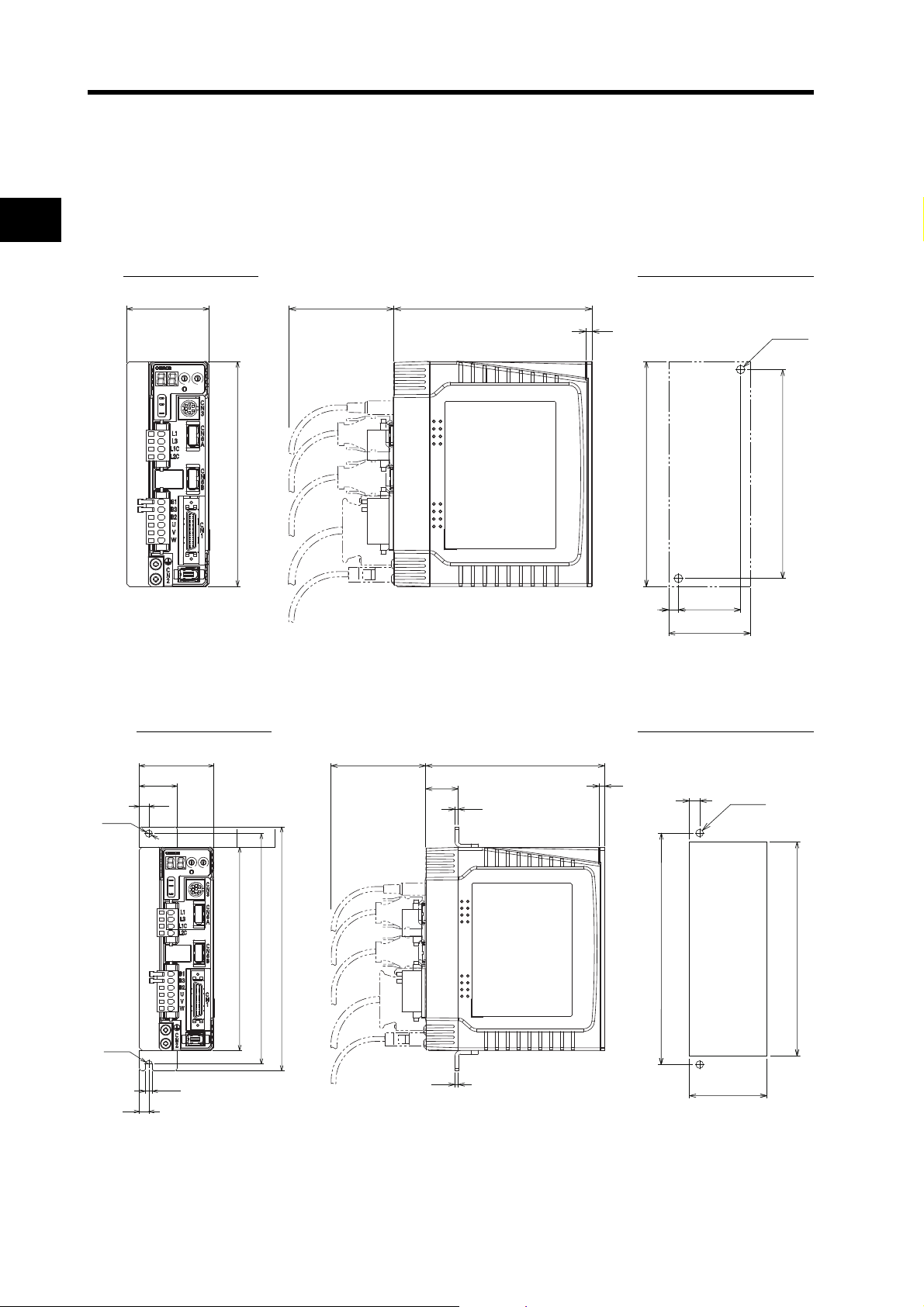
Single-phase 100 VAC: R88D-GNA5L-M L2/-GN01L-ML2 (50 to 100 W)
Single-phase 200 VAC: R88D-GN01H-ML2/-GN02H-ML2 (50 to 200 W)
Wall Mounting
External Dimensions Mounting Hole Dimensions
Standard Models and Dimensions
2-23
Page 57

2-2 External and Mounting Hole Dimensions
(42)
Two, M4
158
170
±0.5
Square
hole
5.2
7
13270
4
180
170
150
21
7
5.2 dia.
R2.6
2.6
24
2.6
8
5
4
3
2
1
0
9
8
7
6
X1
AC SERVO DRIVER
ADR
0
1
2
3
X10
COM
SP
IM
G
Front Panel Mounting (Using Mounting Brackets)
External Dimensions Mounting Hole Dimensions
2
Standard Models and Dimensions
2-24
Page 58
2-2 External and Mounting Hole Dimensions
43
±0.5
6
57
Two, M4
140
±0.5
(150)
13270
4
150
55
0
G
IM
SP
COM
X10
3
2
1
ADR
AC SERVO DRIVER
X1
6
7
8
9
0
1
2
3
4
5
57
Two, M4
158
170
±0.5
Square
hole
8
5.2
7
13270
4
180
170
150
7
5.2 dia.
R2.6
55
28
2.6
24
2.6
0
G
IM
SP
COM
X10
3
2
1
ADR
AC SERVO DRIVER
X1
6
7
8
9
0
1
2
3
4
5
Single-phase 100 VAC: R88D-GN02L-ML2 (200 W)
Single-phase 200 VAC: R88D-GN04H-ML2 (400 W)
2
Wall Mounting
External Dimensions Mounting Hole Dimensions
Standard Models and Dimensions
Front Panel Mounting (Using Mounting Brackets)
External Dimensions Mounting Hole Dimensions
2-25
Page 59
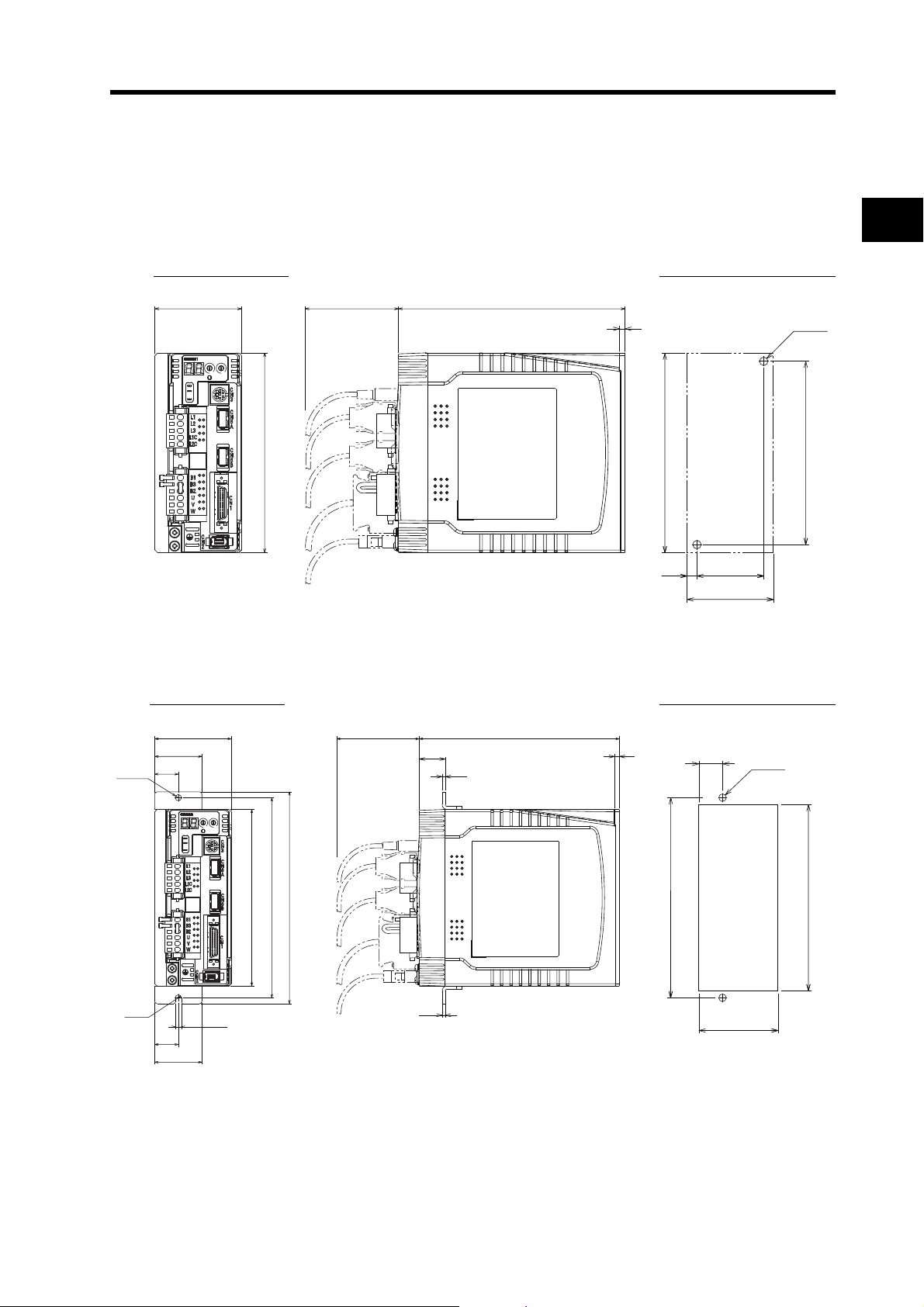
2-2 External and Mounting Hole Dimensions
Single-phase 100 VAC: R88D-GN04L-ML2 (400 W)
Single-phase 200/Three phase VAC: R88D-GN08H-ML2 (750 W)
Wall Mounting
External Dimensions Mounting Hole Dimensions
65
AC SERVO DRIVER
ADR
0
0
1
1
9
2
2
8
3
3
7
4
6
5
X10
X1
COM
SP
IM
G
150
17070
4
(150)
±0.5
8.5
50
Two, M4
±0.5
140
(67)
Front Panel Mounting (Using Mounting Brackets)
2
Standard Models and Dimensions
External Dimensions Mounting Hole Dimensions
17070
4
±0.5
170
21
Two, M4
Square hole
67
5.2 dia.
R2.6
65
40
20
AC SERVO DRIVER
ADR
0
0
1
1
9
2
2
8
3
3
7
4
6
5
X10
X1
COM
SP
IM
G
180
170
150
5.2
22
2.6
2.6
20
40
158
2-26
Page 60
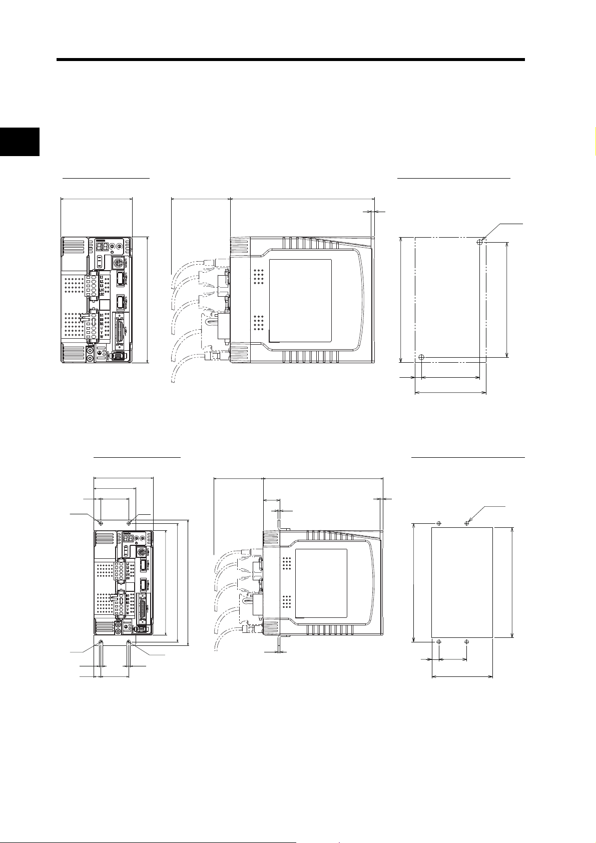
2-2 External and Mounting Hole Dimensions
70
±0.5
8.5
(87)
Two, M4
140
±0.5
(150)
17070
4
150
85
0
G
IM
SP
COM
X10
3
2
1
ADR
AC SERVO DRIVER
X1
6
7
8
9
0
1
2
3
4
5
87
Four, M4
158
170
±0.5
Square hole
40
±0.5
11
5.25.2
17070
4
180
170
150
5.2 dia.
5.2
dia.
R2.6
R2.6
10 40
85
60
4010
2.6
22
2.6
0
G
IM
SP
COM
X10
3
2
1
ADR
AC SERVO DRIVER
X1
6
7
8
9
0
1
2
3
4
5
Single-phase/Three-phase 200 VAC: R88D-GN10H-ML2/-GN15H-ML2
(900 W to 1.5 kW)
2
Wall Mounting
External Dimensions Mounting Hole Dimensions
Standard Models and Dimensions
Front Panel Mounting (Using Mounting Brackets)
External Dimensions Mounting Hole Dimensions
2-27
Page 61
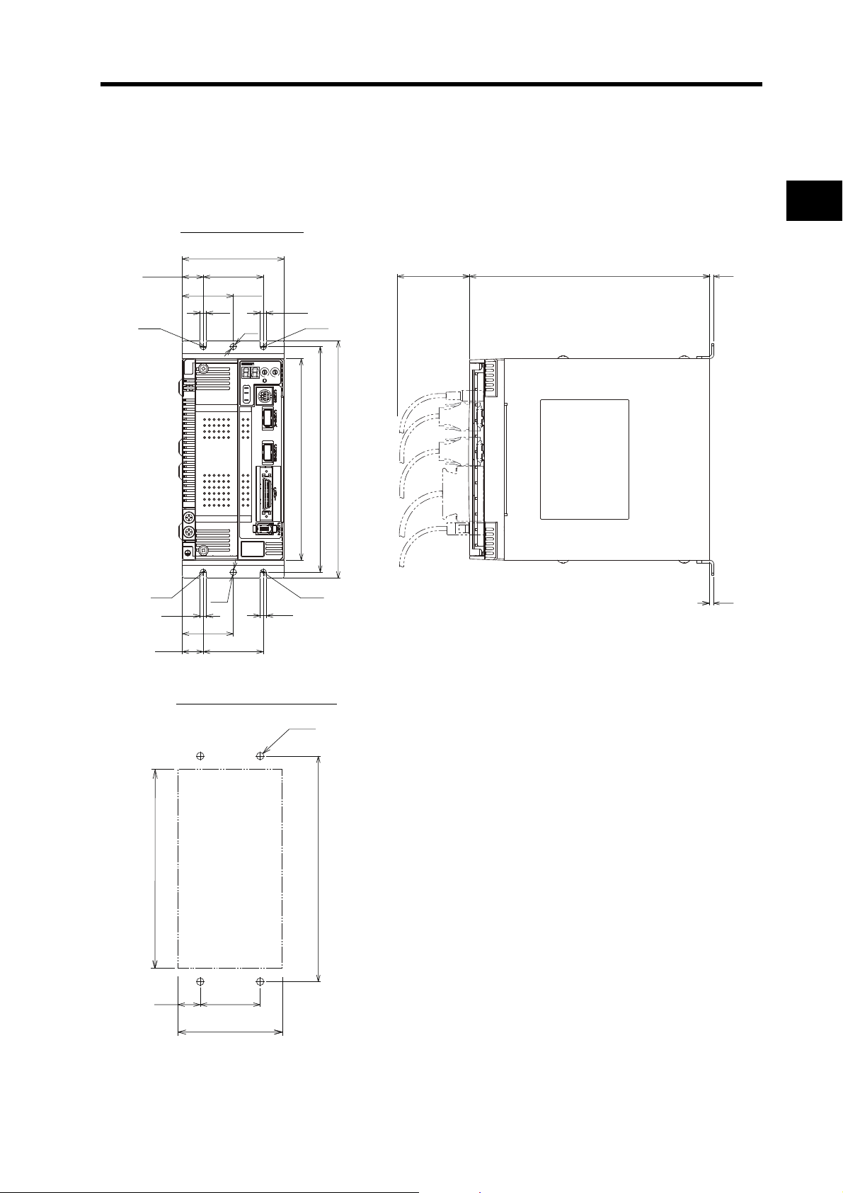
2-2 External and Mounting Hole Dimensions
3.5
3.5
5.25.2
5.25.2
R2.6R2.6
R2.6 R2.6
5.2
dia.
5.2
dia.
20070
198
188
168
85
5017.5
5017.5
42.5
42.5
0
G
IM
SP
COM
X10
3
2
1
ADR
AC SERVO DRIVER
X1
6
7
8
9
0
1
2
3
4
5
(87)
Four, M4
(168)
188
±0.5
18.5 50
±0.5
Three-phase 200 VAC: R88D-GN20H-ML2 (2 kW)
Wall Mounting
External Dimensions
2
Standard Models and Dimensions
Mounting Hole Dimensions
2-28
Page 62
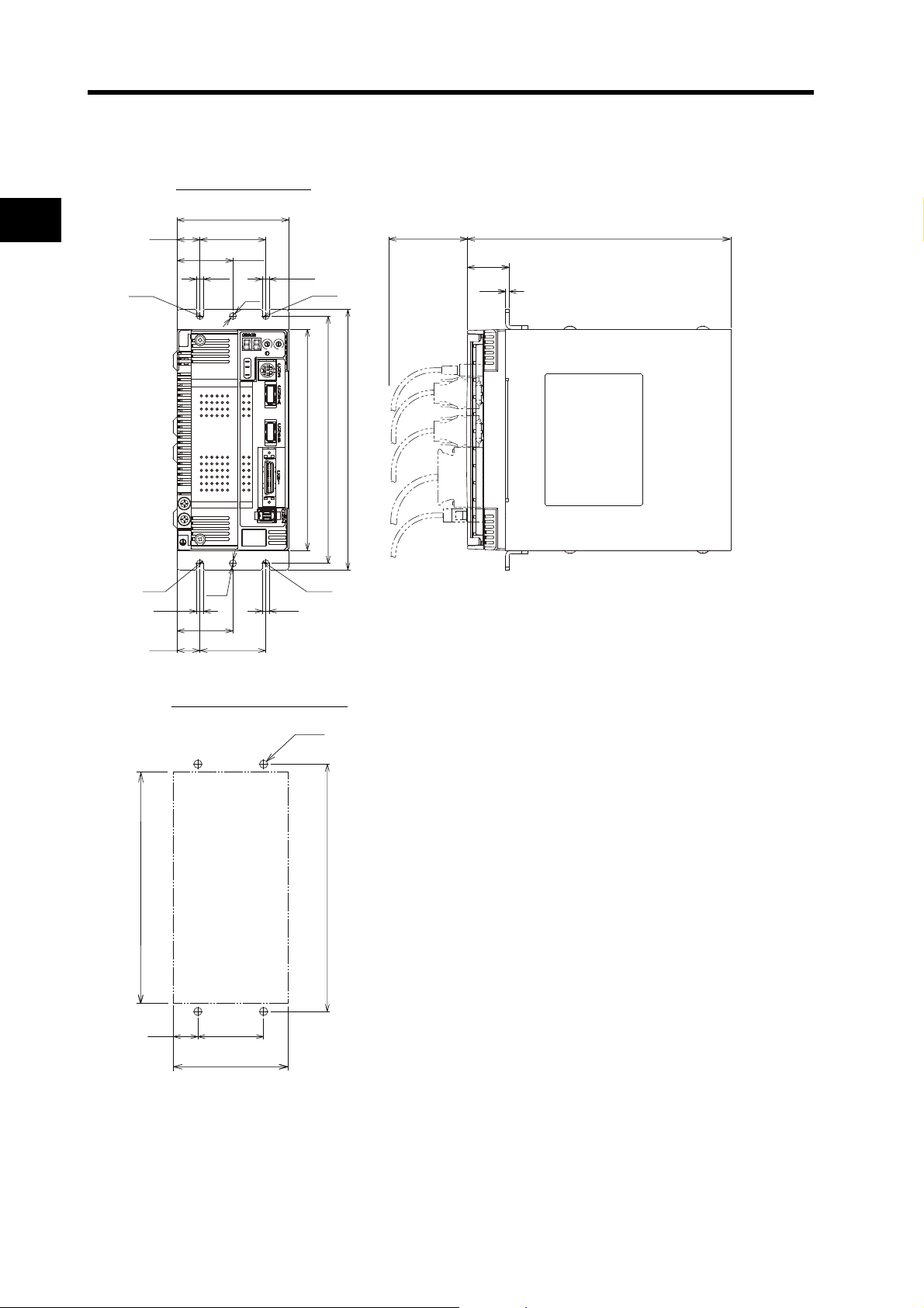
2-2 External and Mounting Hole Dimensions
5.25.2
5.25.2
R2.6R2.6
R2.6 R2.6
5.2
dia.
5.2
dia.
20070
32.1
2.6
198
188
168
85
5017.5
5017.5
42.5
42.5
0
G
IM
SP
COM
X10
3
2
1
ADR
AC SERVO DRIVER
X1
6
7
8
9
0
1
2
3
4
5
89
Four, M4
176
Square hole
188
20.5 50
±0.5
±0.5
Front Panel Mounting (Using Mounting Brackets)
External Dimensions
2
Standard Models and Dimensions
Mounting Hole Dimensions
2-29
Page 63
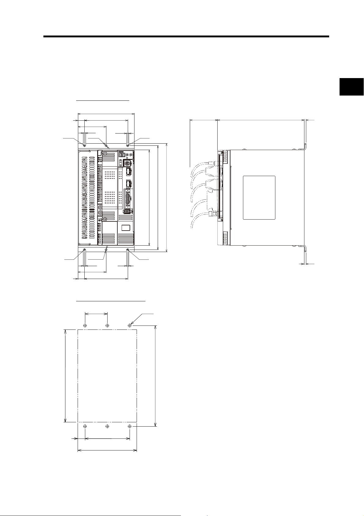
2-2 External and Mounting Hole Dimensions
5.25.2
10015
65
5.2
R2.6
R2.6
R2.6 R2.6
5.2 dia.
5.2 dia.
5.2
200
250
240
220
130
10015
65
70
3.5
3.5
0
G
IM
SP
COM
X10
3
2
1
ADR
AC SERVO DRIVER
X1
6
7
8
9
0
1
2
3
4
5
132
Six, M4
(220)
16
240
±0.5
100
±0.5
50
±0.5
Three-phase 200 VAC: R88D-GN30H-ML2/-GN50H-ML2 (2 to 5 kW)
Wall Mounting
External Dimensions
2
Standard Models and Dimensions
Mounting Hole Dimensions
2-30
Page 64

2-2 External and Mounting Hole Dimensions
5.25.2
10015
65
5.2
R2.6
R2.6
R2.6 R2.6
5.2 dia.
5.2 dia.
5.2
20070
32.3
2.6
250
240
220
130
10015
65
0
G
IM
SP
COM
X10
3
2
1
ADR
AC SERVO DRIVER
X1
6
7
8
9
0
1
2
3
4
5
Front Panel Mounting (Using Mounting Brackets)
External Dimensions
2
Standard Models and Dimensions
Mounting Hole Dimensions
±0.5
50
228
16
Square hole
100
132
±0.5
Six, M4
±0.5
240
2-31
Page 65

2-2 External and Mounting Hole Dimensions
M
W
V
U
B2
B1
L3
L2
L1
250
Six, M4
229
38.5
240
±0.5
90
±0.5
90
±0.5
Square hole
Three-phase 200 VAC: R88D-GN75H-ML2 (7.5 kW)
Front Panel Mounting (Using Mounting Brackets)
External Dimensions
248
90
5.2 5.2 5.2
5.2 5.2 5.2
9037.5
9082.5
AC SERVO DRIVER
ADR
0
0
1
1
9
2
2
8
3
3
7
4
5
6
X10
X1
COM
SP
IM
L1
L2
L3
B1
B2
G
250
220
235
70 (4)
Four, 5.2 dia.
85
45.1
(2.3)
2
339.3
(4)
Standard Models and Dimensions
Mounting Hole Dimensions
2-32
Page 66

2-2 External and Mounting Hole Dimensions
INC
ABS
Three, h: 9
12.5
M3 (depth: 6)
1.8
3
14
(Dimensions of shaft end
with key and tap)
Servomotors
2
3,000-r/min Servomotors
50 W/100 W
R88M-G05030H(-S2)/-G10030L(-S2)/-G10030H(-S2)/-G05030H-B(S2)
/-G10030L-B(S2)/-G10030H-B(S2)
R88M-G05030T(-S2)/-G10030S(-S2)/-G10030T(-S2)/-G05030T-B(S2)
/-G10030S-B(S2)/-G10030T-B(S2)
Encoder
connector
LL 25
230
Standard Models and Dimensions
Brake connector
Motor connector
36
200
LN
8 dia., h: 6
30 dia., h: 7
40 × 40
32
46 dia.
Two, 4.3 dia.
Model
R88M-G05030@ 72 26.5
R88M-G10030
R88M-G05030
R88M-G10030@-B@ 122 46.5
@ 92 46.5
@-B@ 102 26.5
Dimensions (mm)
LL LN
Note The standard models have a straight shaft. Models with a key and tap are indicated with
"S2" at the end of the model number.
2-33
Page 67

3,000-r/min Servomotors
220
200
3G
LL LR
S dia., h: 6
D1 dia.
Motor connector
Encoder
connector
Four, Z dia.
D2 dia., h: 7
Brake connector
KL1
C × C
QK
M(effective depth: L)
b
t1
h
(Dimensions of shaft end
with key and tap)
200 W/400 W/750 W
R88M-G20030L(-S2)/-G40030L(-S2)/-G20030H(-S2)/-G40030H(-S2)
/-G75030H(-S2)/-G20030L-B(S2)/-G40030L-B(S2)
2-2 External and Mounting Hole Dimensions
2
/-G20030H-B(S2)/-G40030H-B(S2)/-G75030H-B(S2)
INC
R88M-G20030S(-S2)/-G40030S(-S2)/-G20030T(-S2)/-G40030T(-S2)
/-G75030T(-S2)/-G20030S-B(S2)/-G40030S-B(S2)
/-G20030T-B(S2)/-G40030T-B(S2)/-G75030T-B(S2)
ABS
Standard Models and Dimensions
Model
R88M-G20030@ 79.5
R88M-G40030
R88M-G75030
R88M-G20030
R88M-G40030
R88M-G75030
@ 99 14 22.5 5h9 5
@ 112.2 351990 70 80 8 53 6 22 6h9 6 3.5
@-B@ 116
@-B@ 135.5 14 22.5 5h9 5
@-B@ 149.2 351990 70 80 8 53 6 22 6h9 6 3.5
LL LR S D1 D2 C G KL1 Z QK b h M t1 L
30
30
11
70 50 60 6.5 43 4.5
11
70 50 60 6.5 43 4.5
Dimensions (mm)
18 4h9 4 M4 2.5 8
18 4h9 4 M4 2.5 8
Note The standard models have a straight shaft. Models with a key and tap are indicated with
"S2" at the end of the model number.
M5
M5
3
3
2-34
10
10
Page 68

2-2 External and Mounting Hole Dimensions
ABS
LL 55
G
3
KL1
84
C × C
Encoder
canon plug
Servomotor
canon plug
Four, Z dia.
D1 dia.
D2 dia., h: 7
19 dia., h: 6
D3 dia.
LL
55
12
3
9
111
84
120×120
Encoder
connector
Servomotor/brake
connector
110 dia., h: 7
22 dia., h: 6
130 dia.
145 dia.
162 dia.
3,000-r/min Servomotors
1 kW/1.5 kW/2 kW
R88M-G1K030T(-S2)/-G1K530T(-S2)/-G2K030T(-S2)/-G1K030T-B(S2)
2
/-G1K530T-B(S2)/-G2K030T-B(S2)
(Dimensions of shaft end
with key and tap)
45
42
Six, h: 9
6
3.5
M5 (depth: 12)
Model
R88M-G1K030
@ 175 100 80 90 120 7 98 6.6
LL D1 D2 C D3 G KL1 Z
R88M-G1K530@ 180
R88M-G2K030
R88M-G1K030
@ 205
@-B@ 200 100 80 90 120 7 98 6.6
R88M-G1K530@-B@ 205
Standard Models and Dimensions
R88M-G2K030
@-B@ 230
Note The standard models have a straight shaft. Models with a key and tap are indicated with
"S2" at the end of the model number.
3,000-r/min Servomotors
3 kW
R88M-G3K030T(-S2)/-G3K030T-B(S2)
Dimensions (mm)
115 95 100 13510103 9
115 95 100 13510103 9
ABS
(Dimensions of the shaft end
with key and tap)
45
41
Eight, h: 9
4
7
2-35
M5 (depth: 12)
Model
R88M-G3K030
R88M-G3K030
@ 217
@-B@ 242
Dimensions (mm)
LL
Note The standard models have a straight shaft. Models with a key and tap are indicated with
"S2" at the end of the model number.
Page 69

3,000-r/min Servomotors
LL
65
12
6
118
84
130×130
Four, 9 dia.
110 dia., h: 7
24 dia., h: 6
165 dia.
Encoder
connector
Servomotor/brake
connector
145 dia.
4 kW/5 kW
R88M-G4K030T(-S2)/-G5K030T(-S2)/-G4K030T-B(S2)/-G5K030T-B(S2)
2-2 External and Mounting Hole Dimensions
ABS
(Dimensions of shaft end
with key and tap)
55
51
Eight, h: 9
7
4
M8 (depth: 20)
2
Model
Dimensions (mm)
LL
R88M-G4K030@ 240
R88M-G5K030
R88M-G4K030
@ 280
@-B@ 265
R88M-G5K030@-B@ 305
Note The standard models have a straight shaft. Models with a key and tap are indicated with
"S2" at the end of the model number.
Standard Models and Dimensions
2-36
Page 70

2-2 External and Mounting Hole Dimensions
INC
ABS
LL LR
F
G
200
220
KL1
C × C
Brake connector
Motor connector
(7)
(7)
Encoder
connector
Four, Z dia.
D2 dia., h: 7
S dia., h: 6
D1 dia.
3,000-r/min Flat Servomotors
100 W/200 W/400 W
2
R88M-GP10030L(-S2)/-GP20030L(-S2)/-GP40030L(-S2)/-GP10030H(-S2)
/-GP20030H(-S2)/-GP40030H(-S2)/-GP10030L-B(S2)/-GP20030L-B(S2)
/-GP40030L-B(S2)/-GP10030H-B(S2)/-GP20030H-B(S2)/-GP40030H-B(S2)
R88M-GP10030S(-S2)/-GP20030S(-S2)/-GP40030S(-S2)/-GP10030T(-S2)
/-GP20030T(-S2)/-GP40030T(-S2)/-GP10030S-B(S2)/-GP20030S-B(S2)
/-GP40030S-B(S2)/-GP10030T-B(S2)/-GP20030T-B(S2)/-GP40030T-B(S2)
Standard Models and Dimensions
Model
R88M-GP10030L
R88M-GP10030H
R88M-GP10030S
R88M-GP10030T
R88M-GP20030L
R88M-GP20030H
R88M-GP20030S
R88M-GP20030T
R88M-GP40030L
R88M-GP40030H
R88M-GP40030S
R88M-GP40030T
R88M-GP10030L-B
@
R88M-GP10030H-B@
R88M-GP10030S-B
R88M-GP10030T-B@
R88M-GP20030L-B
R88M-GP20030H-B@
R88M-GP20030S-B
@
@
@
R88M-GP20030T-B@
R88M-GP40030L-B
@
R88M-GP40030H-B@
R88M-GP40030S-B
R88M-GP40030T-B@
Note The standard models have a straight shaft. Models with a k ey and tap are indicated with "S2" at the end of
@
the model number.
2-37
LL LR S D1 D2 C F G KL1 Z QK b h t1 M L
60.5
87.5
67.5
94.5
82.5
109.5
84.5
111.5
100
127
115
142
(Dimensions of shaft end
with key and tap)
QK
b
t1
h
M (depth: L)
Dimensions (mm)
25 8 70 50 60 3 743 4.5 12.5 3h9 3 1.8 M3 6
30
11
90 70 805 8 53 5.5
18 4h9 4 2.5 M4 8
14 22.5 5h9 5 3 M5 10
25 8 70 50 60 3 743 4.5 12.5 3h9 3 1.8 M3 6
30
11
90 70 805 8 53 5.5
18 4h9 4 2.5 M4 8
14 22.5 5h9 5 3 M5 10
Page 71

2,000-r/min Servomotors
Encoder
connector
Servomotor/brake
connector
LL 55
12
6
118
84
130 × 130
Four, 9 dia.
145 dia.
110 dia., h: 7
22 dia., h: 6
165 dia.
LL LR
12
6
84
S dia., h: 6
118
130 × 130
Four, 9 dia.
145 dia.
110 dia., h: 7
165 dia.
Encoder
connector
Servomotor/brake
connector
1 kW/1.5 kW
R88M-G1K020T(-S2)/-G1K520T(-S2)/-G1K020T-B(S2)/-G1K520T-B(S2)
2-2 External and Mounting Hole Dimensions
ABS
(Dimensions of shaft end
with key and tap)
45
41
Eight, h: 9
4
7
M5 (depth: 12)
2
Model
R88M-G1K020
R88M-G1K520
@ 150
@
R88M-G1K020@-B@
R88M-G1K520@-B@ 200
Note The standard models have a straight shaft. Models with a key and tap are indicated with
“S2” at the end of the model number.
2,000-r/min Servomotors
2 kW/3 kW
R88M-G2K020T(-S2)/-G3K020T(-S2)/-G2K020T-B(S2)/-G3K020T-B(S2)
Dimensions (mm)
LL
175
ABS
(Dimensions of shaft end
with key and tap)
LW
QK
Eight, h: 9
7
Standard Models and Dimensions
4
M (depth: L)
Model
R88M-G2K020
@ 20055224541M512
Dimensions (mm)
LL LR S LW QK M L
R88M-G3K020@ 25065245551M8 20
R88M-G2K020
R88M-G3K020
@-B@ 22555224541M512
@-B@ 27565245551M8 20
Note The standard models have a straight shaft. Models with a key and tap are indicated with
"S2" at the end of the model number.
2-38
Page 72

2-2 External and Mounting Hole Dimensions
LL LR
18
3.2
KL1
84
C × C
D1 dia.
D2 dia., h: 7
S dia.,h: 6
D3 dia.
Four, Z dia.
Encoder
connector
Servomotor/brake
connector
QK
t1
h
b
M (depth: L)
(Dimensions of shaft end
with key and tap)
2,000-r/min Servomotors
4 kW/5 kW
2
R88M-G4K020T(-S2)/-G5K020T(-S2)/-G4K020T-B(S2)/-G5K020T-B(S2)
ABS
Model
R88M-G4K020
@ 242 65 28 165 130 150 190 128 11 51 8h9 7 4 M8 20
LL LR S D1 D2 C D3 KL1 Z QK b h t1 M L
R88M-G5K020@ 225 70 35 200 114.3 176 233 143 13.5 50 10h9 8 5 M12 25
R88M-G4K020
R88M-G5K020
@-B@ 267 65 28 165 130 150 190 128 11 51 8h9 7 4 M8 20
@-B@ 250 70 35 200 114.3 176 233 143 13.5 50 10h9 8 5 M12 25
Note The standard models have a straight shaft. Models with a key and tap are indicated with
"S2" at the end of the model number.
Standard Models and Dimensions
Dimensions (mm)
2-39
Page 73

1,500-r/min Servomotors
90
96
M16 (depth:32)
12, h: 9
8
5
(Dimensions of shaft end
with key and tap)
Eye-bolt
Nominal diameter: 10
Brake connector
LL 113
24
3.2
183
84
176 × 176
Four, 13.5 dia.
200 dia.
114.3 dia., h: 7
42 dia., h: 6
233 dia.
Motor
connector
Encoder
connector
7.5 kW
R88M-G7K515T(-S2)/-G7K515T-B(S2)
2-2 External and Mounting Hole Dimensions
ABS
2
Model
R88M-G7K515
@ 340.5
Dimensions (mm)
LL
R88M-G7K515@-B@ 380.5
Note The standard models have a straight shaft. Models with a key and tap are indicated with
"S2" at the end of the model number.
Standard Models and Dimensions
2-40
Page 74
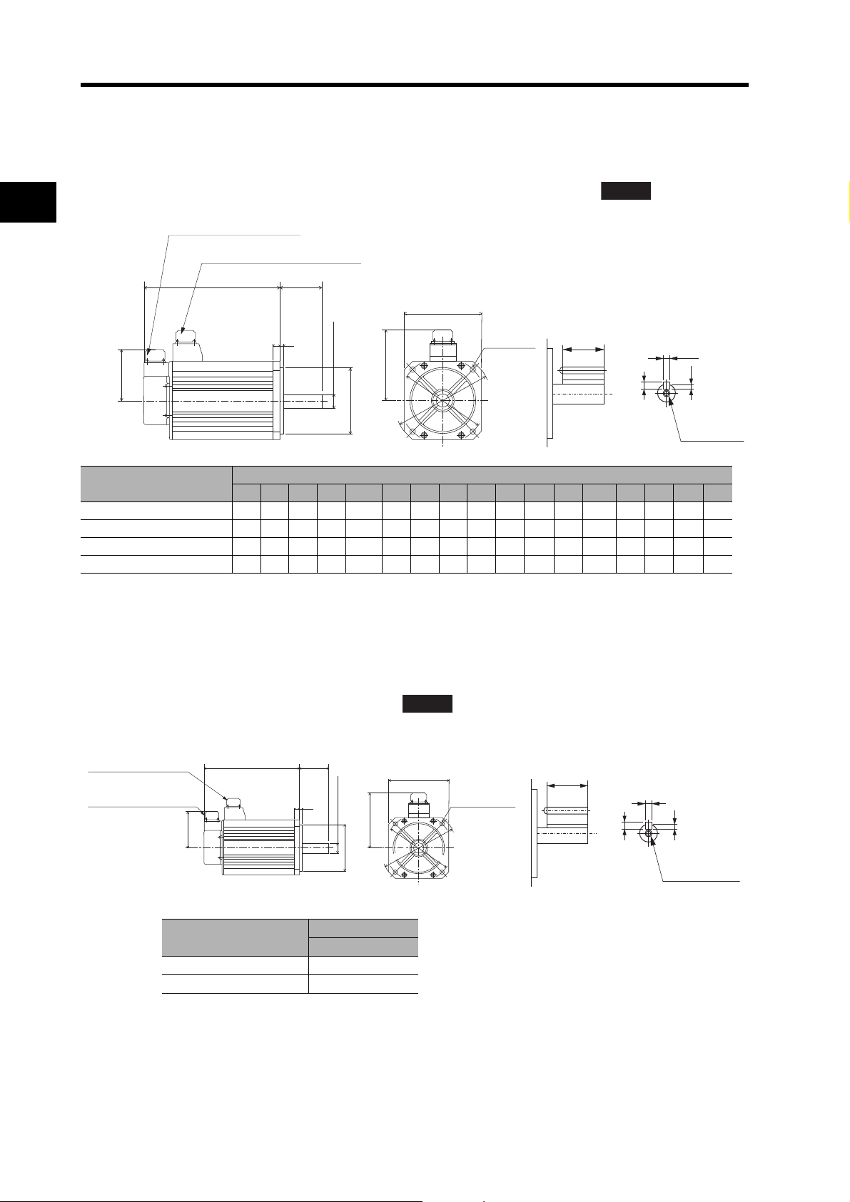
2-2 External and Mounting Hole Dimensions
C × C
S dia., h: 6
D2 dia., h: 7
LR
FLLG
KL1
84
Encoder connector
Servomotor/brake connector
Four, Z dia.
D1 dia.
D3 dia.
QK
b
t1
h
M (depth: L)
(Dimensions of shaft end
with key and tap)
ABS
35 dia
.,
h: 6
114.3 dia
.,
h: 7
80
3.2
LL
18
84
176 × 176
143
Four, 13.5 dia.
Encoder connector
Servomotor/brake
connector
233 dia.
200 dia.
1,000-r/min Servomotors
900 W/2 kW
2
R88M-G90010T(-S2)/-G2K010T(-S2)/-G90010T-B(S2)/-G2K010T-B(S2)
ABS
Model
R88M-G90010
R88M-G2K010
R88M-G90010
R88M-G2K010
Standard Models and Dimensions
Note The standard models have a straight shaft. Models with a k ey and tap are indicated with "S2" at the end of
@ 175 70 22 145 110 130 165 6 12 118 9418h9 7 4 M5 12
@ 182 80 35 200 114.3 176 233 3.2 18 143 13.5 50 10h9 8 5M1225
@-B@ 200 70 22 145 110 130 165 6 12 118 9418h9 7 4 M5 12
@-B@ 207 80 35 200 114.3 176 233 3.2 18 143 13.5 50 10h9 8 5M1225
LL LR S D1 D2 C D3 F G KL1 Z QK b h t1 M L
the model number.
1,000-r/min Servomotors
3 kW
R88M-G3K010T(-S2)/-G3K010T-B(S2)
Dimensions (mm)
(Dimensions of shaft end
with key and tap)
50
10, h: 9
5
8
M12 (depth: 25)
2-41
Model
Dimensions (mm)
LL
R88M-G3K010@ 222
R88M-G3K010
@-B@ 271
Note The standard models have a straight shaft. Models with a key and tap are indicated with
"S2" at the end of the model number.
Page 75

1,000-r/min Servomotors
114.3 dia., h: 7
42 dia., h: 6
113
LL
24
3.2
84
176 × 176
143
Four, 13.5 dia.
Encoder connector
Servomotor/brake
connector
Eye-bolt
Nominal
diameter: 10
200 dia.
233 dia.
90
96
M16 (depth: 32)
12, h: 9
8
5
(Dimensions of shaft end
with key and tap)
4.5 kW
R88M-G4K510T(-S2)/-G4K510T-B(S2)
2-2 External and Mounting Hole Dimensions
ABS
(Dimensions of shaft end
with key and tap)
90
12, h: 9
5
8
M16 (depth: 32)
2
Model
R88M-G4K510
R88M-G4K510
@ 300.5
@-B@ 337.5
Note The standard models have a straight shaft. Models with a key and tap are indicated with
"S2" at the end of the model number.
1,000-r/min Servomotors
6 kW
R88M-G6K010T(-S2)/-G6K010T-B(S2)
Brake connector
Motor
connector
Encoder
connector
Eye-bolt
Nominal diameter: 10
Dimensions (mm)
LL
Standard Models and Dimensions
ABS
176 × 176
Four, 13.5 dia.
42 dia., h: 6
233 dia.
R88M-G6K010
R88M-G6K010
Note The standard models have a straight shaft. Models with a key and tap are indicated with
114.3 dia., h: 7
Model
Dimensions (mm)
LL
@ 340.5
@-B@ 380.5
"S2" at the end of the model number.
200 dia.
2-42
Page 76

2-2 External and Mounting Hole Dimensions
Mini DIN 8-pin
MD connector
(62)
(24)
(15)
(1500)
M3 (depth: 5)
(114)
(15)
Parameter Unit Dimensions
2
R88A-PR02G Hand-held Parameter Unit
Standard Models and Dimensions
2-43
Page 77
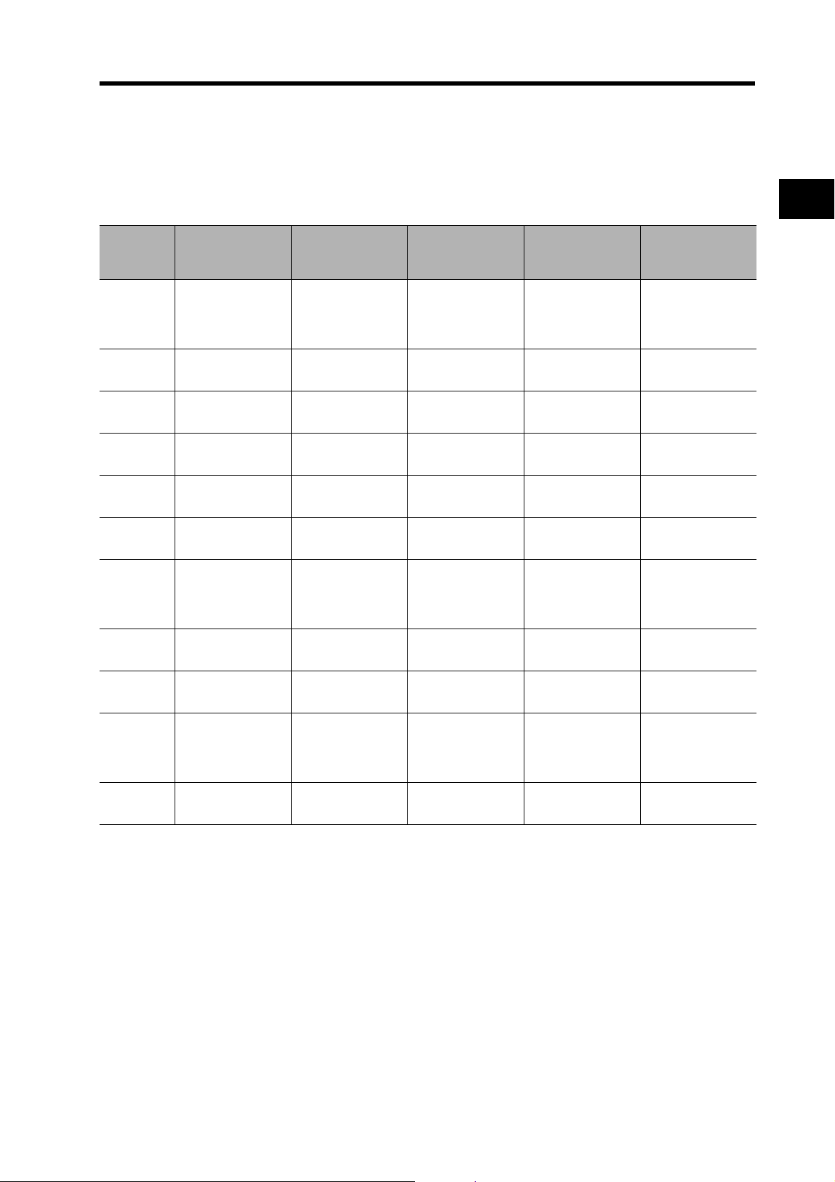
2-2 External and Mounting Hole Dimensions
Servomotor and Decelerator Combinations
3,000-r/min Servomotors
Motor model 1/5
R88GR88MG05030@
R88MG10030@
R88MG20030@
R88MG40030@
R88MG75030@
R88MG1K030T
R88MG1K530T
HPG11A05100B
(Also used with
R88M-G10030
R88G-
HPG11A05100B
R88G-
HPG14A05200B
R88G-
HPG14A05400B
R88G-
HPG20A05750B
R88G-
HPG32A051K0B
R88G-
HPG32A052K0B
(Also used with
R88M-G2K030T)
R88G-
@
HPG11A09050B
(
@
)
R88G-
@
HPG14A11100B
R88G-
@
HPG14A11200B
R88G-
@
HPG20A11400B
R88G-
@
HPG20A11750B
R88G-
@
HPG32A111K0B
R88G-
HPG32A112K0B
@
(Also used with
R88M-G2K030T)
1/11
(1/9 for flange size
No.11)
@
Gear ratio 1/9
)
@
@
@
@
@
@
1/21 1/33 1/45
R88GHPG14A21100B
(Also used with
R88M-G10030
R88GHPG14A21100B
R88GHPG20A21200B
R88GHPG20A21400B
R88GHPG32A21750B
R88GHPG32A211K0B
R88GHPG32A211K5B
@
R88G-
@
HPG14A33050B
)
R88G-
@
HPG20A33100B
R88G-
@
HPG20A33200B
R88G-
@
HPG32A33400B
R88G-
@
HPG32A33750B
R88G-
@
HPG32A331K0B
R88G-
HPG50A332K0B
@
(Also used with
R88M-G2K030T)
R88G-
@
HPG14A45050B
R88G-
@
HPG20A45100B
R88G-
@
HPG20A45200B
R88G-
@
HPG32A45400B
R88G-
@
HPG32A45750B
R88G-
@
HPG50A451K0B
R88G-
@
HPG50A451K5B
2
@
@
@
@
@
@
Standard Models and Dimensions
@
R88MG2K030T
R88MG3K030T
R88MG4K030T
R88MG5K030T
R88G-
HPG32A052K0B
R88G-
HPG32A053K0B
R88G-
HPG32A054K0B
R88G-
HPG50A055K0B
R88G-
@
HPG32A112K0B
R88G-
@
HPG50A113K0B
R88G-
HPG50A115K0B
@
(Also used with
R88M-G5K030T)
R88G-
@
HPG50A115K0B
R88G-
@
HPG50A212K0B
R88G-
@
HPG50A213K0B
@
--- --- ---
--- --- ---
@
R88G-
@
HPG50A332K0B
--- ---
@
---
@
2-44
Page 78
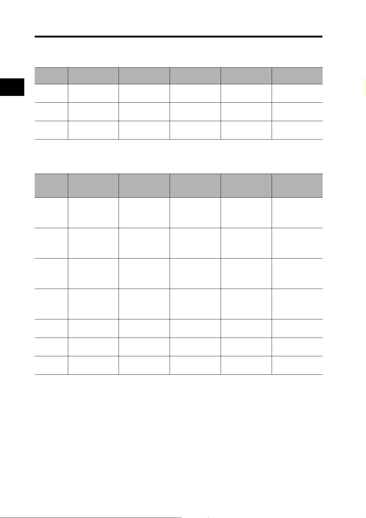
2-2 External and Mounting Hole Dimensions
3,000-r/min Flat Servomotors
Motor model 1/5 1/11 1/21 1/33 1/45
2
Standard Models and Dimensions
R88MGP10030@
R88MGP20030
R88MGP40030
Motor model 1/5
R88MG1K020T
R88MG1K520T
R88MG2K020T
R88MG3K020T
R88GHPG11A05100PB
R88G-
@
HPG14A05200PB
R88G-
@
HPG20A05400PB
2
,000-r/min Servomotors
R88GHPG32A053K0B
(Also used with
R88M-G3K030T)
R88GHPG32A053K0B
(Also used with
R88M-G3K030T)
R88GHPG32A053K0B
(Also used with
R88M-G3K030T)
R88GHPG32A054K0B
(Also used with
R88M-G4K030T)
R88G-
@
HPG14A11100PB
R88G-
@
HPG20A11200PB
R88G-
@
HPG20A11400PB
(1/12 for flange size
No.65)
R88GHPG32A112K0SB
@
(Also used with
R88M-G2K020T)
R88GHPG32A112K0SB
@
(Also used with
R88M-G2K020T)
@
R88GHPG32A112K0SB
R88G-
@
HPG50A115K0B
(Also used with
R88M-G5K030T)
1/11
R88G-
@
HPG14A21100PB
R88G-
@
HPG20A21200PB
R88G-
@
HPG20A21400PB
1/21
(1/20 for flange size
No.65)
R88G-
@
HPG32A211K0SB
R88GHPG50A213K0B
@
(Also used with
R88M-G3K030T)
R88GHPG50A213K0B
@
(Also used with
R88M-G3K030T)
@
R88GHPG50A213K0SB
R88G-
@
HPG20A33100PB
R88G-
@
HPG20A33200PB
R88G-
@
HPG32A33400PB
1/33
(1/25 for flange size
No.65)
R88GHPG50A332K0SB
@
(Also used with
R88M-G2K020T)
R88GHPG50A332K0SB
@
(Also used with
R88M-G2K020T)
@
R88GHPG50A332K0SB
R88G-
@
HPG65A253K0SB
R88G-
@
HPG20A45100PB
R88G-
@
HPG20A45200PB
R88G-
@
HPG32A45400PB
1/45
R88G-
@
HPG50A451K0SB
@
---
---
@
---
@
@
@
@
@
R88MG4K020T
R88MG5K020T
R88MG7K515T
2-45
R88GHPG50A054K0SB
R88GHPG50A055K0SB
R88GHPG65A057K5SB
R88G-
@
HPG50A114K0SB
R88G-
@
HPG50A115K0SB
R88G-
@
HPG65A127K5SB
R88G-
@
HPG65A204K0SB
R88G-
@
HPG65A205K0SB
--- --- ---
@
R88G-
@
HPG65A254K0SB
R88G-
@
HPG65A255K0SB
---
@
---
@
Page 79
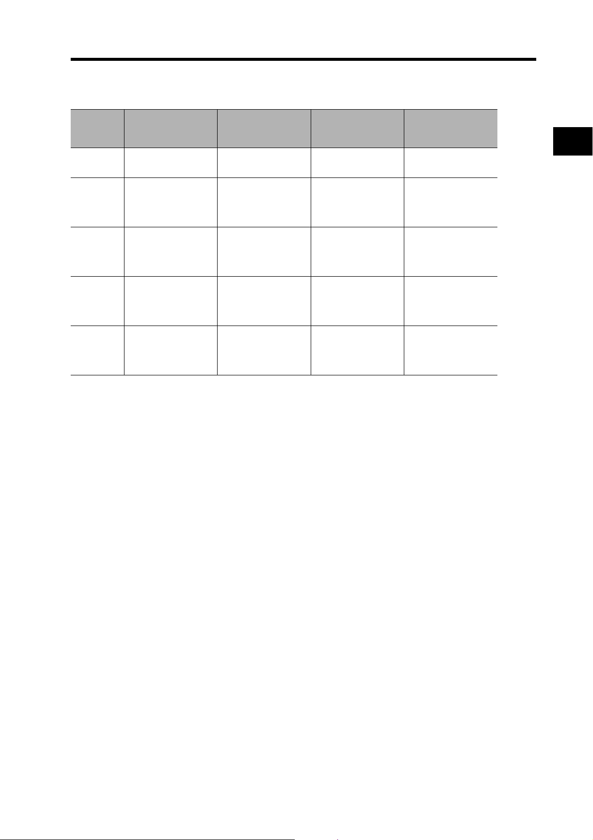
1,000-r/min Servomotors
2-2 External and Mounting Hole Dimensions
Motor model 1/5
R88MG90010T
R88MG2K010T
R88MG3K010T
R88MG4K510T
R88MG6K010T
R88G-
HPG32A05900TB@
R88G-
HPG32A052K0TB@
R88G-
HPG50A055K0SB@
(Also used with R88M-
G5K020T)
R88G-
HPG50A054K5TB
R88G-
HPG65A057K5SB@
(Also used with R88M-
G7K515T)
1/11
(1/12 for flange size
No.65)
R88GHPG32A11900TB@
R88GHPG50A112K0TB@
R88GHPG50A115K0SB
(Also used with R88M-
G5K020T)
R88GHPG65A127K5SB@
@
(Also used with R88M-
G7K515T)
R88GHPG65A127K5SB@
(Also used with R88M-
G7K515T)
1/21
(1/20 for flange size
No.65)
R88GHPG50A21900TB@
R88GHPG50A212K0TB@
R88GHPG65A205K0SB
@
(Also used with R88M-
G5K020T)
R88GHPG65A204K5TB@
--- ---
1/33
(1/25 for flange size
No.65)
R88GHPG50A33900TB@
R88GHPG65A255K0SB@
(Also used with R88M-
G5K020T)
R88GHPG65A255K0SB
@
(Also used with R88M-
G5K020T)
---
2
@
Standard Models and Dimensions
2-46
Page 80

2-2 External and Mounting Hole Dimensions
Decelerator Dimensions
2
Backlash = 3’ Max.
Decelerators for 3,000-r/min Servomotors
Model
1/5 R88G-HPG11A05100B@ 39.5 42 40 40×40 46 46 40.0 39.5 29 27 2.2 15
1/9 R88G-HPG11A09050B@ 39.5 42 40 40×40 46 46 40.0 39.5 29 27 2.2 15
50 W
1/21 R88G-HPG14A21100B@ 64.0 58 60 60×60 70 46 56.0 55.5 40 37 2.5 21
1/33 R88G-HPG14A33050B
1/45 R88G-HPG14A45050B@ 64.0 58 60 60×60 70 46 56.0 55.5 40 37 2.5 21
1/5 R88G-HPG11A05100B@ 39.5 42 40 40×40 46 46 40.0 39.5 29 27 2.2 15
1/11 R88G-HPG14A11100B@ 64.0 58 60 60×60 70 46 56.0 55.5 40 37 2.5 21
100 W
200 W
Standard Models and Dimensions
100 W
200 W
1/21 R88G-HPG14A21100B
1/33 R88G-HPG20A33100B@ 66.5 80 90 55 dia. 105 46 85.0 84.0 59 53 7.5 27
1/45 R88G-HPG20A45100B@ 66.5 80 90 55 dia. 105 46 85.0 84.0 59 53 7.5 27
1/5 R88G-HPG14A05200B@ 64.0 58 60 60×60 70 70 56.0 55.5 40 37 2.5 21
1/11 R88G-HPG14A11200B@ 64.0 58 60 60×60 70 70 56.0 55.5 40 37 2.5 21
1/21 R88G-HPG20A21200B@ 71.0 80 90 89 dia. 105 70 85.0 84.0 59 53 7.5 27
1/33 R88G-HPG20A33200B
1/45 R88G-HPG20A45200B@ 71.0 80 90 89 dia. 105 70 85.0 84.0 59 53 7.5 27
Model
1/5 R88G-HPG11A05100B@ 5 8 20 3.4 M4×9M3 15 3 3 1.8 M3 6
1/9 R88G-HPG11A09050B
1/21 R88G-HPG14A21100B@ 8 16 28 5.5 M4×10 M3 25 5 5 3 M4 8
50 W
1/33 R88G-HPG14A33050B@ 8 16 28 5.5 M4×10 M3 25 5 5 3 M4 8
1/45 R88G-HPG14A45050B@ 8 16 28 5.5 M4×10 M3 25 5 5 3 M4 8
1/5 R88G-HPG11A05100B@ 5 8 20 3.4 M4×9M3 15 3 3 1.8 M3 6
1/11 R88G-HPG14A11100B@ 8 16 28 5.5 M4×10 M3 25 5 5 3 M4 8
1/21 R88G-HPG14A21100B@ 8 16 28 5.5 M4×10 M3 25 5 5 3 M4 8
1/33 R88G-HPG20A33100B
1/45 R88G-HPG20A45100B@ 10 25 42 9.0 M4×10 M4 36 8 7 4.0 M6 12
1/5 R88G-HPG14A05200B@ 8 16 28 5.5 M4×10 M4 25 5 5 3 M4 8
1/11 R88G-HPG14A11200B@ 8 16 28 5.5 M4×10 M4 25 5 5 3 M4 8
1/21 R88G-HPG20A21200B@ 10 25 42 9.0 M4×10 M4 36 8 7 4.0 M6 12
1/33 R88G-HPG20A33200B@ 10 25 42 9.0 M4×10 M4 36 8 7 4.0 M6 12
1/45 R88G-HPG20A45200B@ 10 25 42 9.0 M4×10 M4 36 8 74.0 M612
Note1. The standard models have a straight shaft.
Note2. Models with a key and tap are indicated with "J" at the end of the model number (the suffix shown in the
box). (Example: R88G-HPG11A05100BJ)
@ 64.0 58 60 60×60 70 46 56.0 55.5 40 37 2.5 21
@ 64.0 58 60 60×60 70 46 56.0 55.5 40 37 2.5 21
@ 71.0 80 90 89 dia. 105 70 85.0 84.0 59 53 7.5 27
@ 5 8 20 3.4 M4×9M3 15 3 3 1.8 M3 6
@ 10 25 42 9.0 M4×10 M4 36 8 7 4.0 M6 12
Dimensions (mm)
LM LR C1 C2 D1 D2 D3 D4 D5 E F1 F2
Dimensions (mm)
Tap
dimensions
G S T Z1 Z2 AT
Key dimensions
*1
QK b h t1 M L
2-47
Page 81

2-2 External and Mounting Hole Dimensions
C1 × C1
Four, Z1 dia.
S dia.,h: 7
D5 dia.
D4 dia.
D3 dia.
E
T
F1
F2LRG
LM
C2 × C2
D2 dia.
D1 dia.
Four, Z2 dia.
Set bolt (AT)
C2 dia.
Four, Z2 dia.
Set bolt (AT)
D2 dia.
Model
1/5 R88G-HPG14A05400B@ 64.0 58 60 60×60 70 70 56.0 55.5 40 37 2.5 21
1/11 R88G-HPG20A11400B@ 71.0 80 90 89 dia. 105 70 85.0 84.0 59 53 7.5 27
400 W
750 W
400 W
750 W
*1. This is the set bolt.
1/21 R88G-HPG20A21400B@ 71.0 80 90 89 dia. 105 70 85.0 84.0 59 53 7.5 27
1/33 R88G-HPG32A33400B@ 104.0 133 120 122 dia. 135 70 115.0 114.0 84 98 12.5 35
1/45 R88G-HPG32A45400B@ 104.0 133 120 122 dia. 135 70 115.0 114.0 84 98 12.5 35
1/5 R88G-HPG20A05750B@ 78.0 80 90 80×80 105 90 85.0 84.0 59 53 7.5 27
1/11 R88G-HPG20A11750B@ 78.0 80 90 80×80 105 90 85.0 84.0 59 53 7.5 27
1/21 R88G-HPG32A21750B@ 104.0 133 120 122 dia. 135 90 115.0 114.0 84 98 12.5 35
1/33 R88G-HPG32A33750B@ 104.0 133 120 122 dia. 135 90 115.0 114.0 84 98 12.5 35
1/45 R88G-HPG32A45750B@ 104.0 133 120 122 dia. 135 90 115.0 114.0 84 98 12.5 35
Model
1/5 R88G-HPG14A05400B@ 8 16 28 5.5 M4×10 M4 25 5 5 3 M4 8
1/11 R88G-HPG20A11400B@ 10 25 42 9.0 M4×10 M4 36 8 7 4.0 M6 12
1/21 R88G-HPG20A21400B@ 10 25 42 9.0 M4×10 M4 36 8 7 4.0 M6 12
1/33 R88G-HPG32A33400B@ 13 40 82 11.0 M4×10 M4 70 12 8 5.0 M10 20
1/45 R88G-HPG32A45400B@ 13 40 82 11.0 M4×10 M4 70 12 8 5.0 M10 20
1/5 R88G-HPG20A05750B@ 10 25 42 9.0 M5×12 M4 36 8 7 4.0 M6 12
1/11 R88G-HPG20A11750B@ 10 25 42 9.0 M5×12 M4 36 8 7 4.0 M6 12
1/21 R88G-HPG32A21750B@ 13 40 82 11.0 M5×12 M6 70 12 8 5.0 M10 20
1/33 R88G-HPG32A33750B@ 13 40 82 11.0 M5×12 M6 70 12 8 5.0 M10 20
1/45 R88G-HPG32A45750B@ 13 40 82 11.0 M5×12 M6 70 12 8 5.0 M10 20
Dimensions (mm)
LM LR C1 C2 D1 D2 D3 D4 D5 E F1 F2
Dimensions (mm)
Tap
dimensions
G S T Z1 Z2 AT
Key dimensions
*1
QK b h t1 M L
2
Standard Models and Dimensions
Outline Drawings
QK
h
b
t1
M (depth: L)
Key and Tap Dimensions
2-48
Page 82

2-2 External and Mounting Hole Dimensions
Model
1/5 R88G-HPG32A051K0B
1/11 R88G-HPG32A111K0B@ 104 133 120
1 kW
2
1.5 kW
Standard Models and Dimensions
Note1. The standard models have a straight shaft.
1/21 R88G-HPG32A211K0B
1/33 R88G-HPG32A331K0B@ 104 133 120
1/45 R88G-HPG50A451K0B
1/5 R88G-HPG32A052K0B@ 110 133 120
1/11 R88G-HPG32A112K0B
1/21 R88G-HPG32A211K5B@ 110 133 120
1/33 R88G-HPG50A332K0B
1/45 R88G-HPG50A451K5B@ 123 156 170
1/5 R88G-HPG32A052K0B
1/11 R88G-HPG32A112K0B@ 110 133 120
2 kW
1/21 R88G-HPG50A212K0B
1/33 R88G-HPG50A332K0B@ 123 156 170
1/5 R88G-HPG32A053K0B
1/11 R88G-HPG50A113K0B@ 123 156 170
3 kW
1/21 R88G-HPG50A213K0B
4 kW
5 kW
1/5 R88G-HPG32A054K0B@ 129 133 120 130×130135 145 115 114 8498 12.5 35
1/11 R88G-HPG50A115K0B
1/5 R88G-HPG50A055K0B@ 149 156 170 130×130 190 145 165 163 122 103 12.0 53
1/11 R88G-HPG50A115K0B
@ 104 133 120
@ 104 133 120
@ 123 156 170
@ 110 133 120
@ 123 156 170
@ 110 133 120
@ 123 156 170
@ 107 133 120 130×130135 145 115 114 8498 12.5 35
@ 123 156 170
@ 149 156 170 130×130 190 145 165 163 122 103 12.0 53
@ 149 156 170 130×130 190 145 165 163 122 103 12.0 53
Note2. Models with a key and tap are indicated with "J" at the end of the model number (the suffix shown in the
box). (Example: R88G-HPG32A051K0BJ)
Dimensions (mm)
LM LR C1 C2 D1 D2 D3 D4 D5 E F1 F2
122 dia.
122 dia.
122 dia.
122 dia.
170 dia.
135 dia.
135 dia.
135 dia.
170 dia.
170 dia.
135 dia.
135 dia.
170 dia.
170 dia.
170 dia.
170 dia.
135 100 115 114 8498 12.5 35
135 100 115 114 8498 12.5 35
135 100 115 114 8498 12.5 35
135 100 115 114 8498 12.5 35
190 100 165 163 122 103 12.0 53
135 115 115 114 8498 12.5 35
135 115 115 114 8498 12.5 35
135 115 115 114 8498 12.5 35
190 115 165 163 122 103 12.0 53
190 115 165 163 122 103 12.0 53
135 115 115 114 8498 12.5 35
135 115 115 114 8498 12.5 35
190 115 165 163 122 103 12.0 53
190 115 165 163 122 103 12.0 53
190 145 165 163 122 103 12.0 53
190 145 165 163 122 103 12.0 53
2-49
Page 83

Model
E
T
F1
F2LRG
LM
S dia.,h: 7
D5 dia.
D4 dia.
D3 dia.
Four, Z2 dia.
Set bolt (AT)
C2 dia.
C1 × C1
D1 dia.
Four, Z1 dia.
D2 dia.
C2 × C2
Four, Z2 dia.
Set bolt (AT)
D2 dia.
QK
Key and Tap Dimensions
b
h
t1
M (depth: L)
1/5 R88G-HPG32A051K0B@ 13 40 8211M6×12 M6 70 12 8 5.0 M10 20
1/11 R88G-HPG32A111K0B
1/21 R88G-HPG32A211K0B@ 13 40 8211M6×12 M6 70 12 8 5.0 M10 20
1 kW
1/33 R88G-HPG32A331K0B
1/45 R88G-HPG50A451K0B@ 16 50 8214M6×10 M6 70 14 9 5.5 M10 20
1/5 R88G-HPG32A052K0B
1/11 R88G-HPG32A112K0B@ 13 40 8211M8×10 M6 70 12 8 5.0 M10 20
1.5 kW
*1. This is the set bolt.
1/21 R88G-HPG32A211K5B
1/33 R88G-HPG50A332K0B
1/45 R88G-HPG50A451K5B
1/5 R88G-HPG32A052K0B
1/11 R88G-HPG32A112K0B
2 kW
1/21 R88G-HPG50A212K0B
1/33 R88G-HPG50A332K0B
1/5 R88G-HPG32A053K0B@ 13 40 8211M8×18 M6 70 12 8 5.0 M10 20
3 kW
1/11 R88G-HPG50A113K0B
1/21 R88G-HPG50A213K0B@ 16 50 8214M8×16 M6 70 14 9 5.5 M10 20
4 kW
5 kW
1/5 R88G-HPG32A054K0B
1/11 R88G-HPG50A115K0B@ 16 50 8214M8×25 M6 70 14 9 5.5 M10 20
1/5 R88G-HPG50A055K0B
1/11 R88G-HPG50A115K0B
2-2 External and Mounting Hole Dimensions
Dimensions (mm)
Key dimensions
G S T Z1 Z2 AT
*1
QK b h t1 M L
@ 13 40 8211M6×12 M6 70 12 8 5.0 M10 20
@ 13 40 8211M6×12 M6 70 12 8 5.0 M10 20
@ 13 40 8211M8×10 M6 70 12 8 5.0 M10 20
@ 13 40 8211M8×10 M6 70 12 8 5.0 M10 20
@ 16 50 8214M8×10 M6 70 14 9 5.5 M10 20
@ 16 50 8214M8×10 M6 70 14 9 5.5 M10 20
@ 13 40 8211M8×10 M6 70 12 8 5.0 M10 20
@ 13 40 8211M8×10 M6 70 12 8 5.0 M10 20
@ 16 50 8214M8×10 M6 70 14 9 5.5 M10 20
@ 16 50 8214M8×10 M6 70 14 9 5.5 M10 20
@ 16 50 8214M8×16 M6 70 14 9 5.5 M10 20
@ 13 40 8211M8×25 M6 70 12 8 5.0 M10 20
@ 16 50 8214M8×25 M6 70 14 9 5.5 M10 20
@ 16 50 8214M8×25 M6 70 14 9 5.5 M10 20
Tap
dimensions
2
Standard Models and Dimensions
Outline Drawings
2-50
Page 84

2-2 External and Mounting Hole Dimensions
Decelerators for 2,000-r/min Servomotors
Model
2
1 kW
1.5 kW
2 kW
3 kW
Standard Models and Dimensions
1 kW
1.5 kW
2 kW
3 kW
1/5 R88G-HPG32A053K0B
1/11 R88G-HPG32A112K0SB@ 107 133 120 130×130135 145 115 114 8498 12.5 35
1/21 R88G-HPG32A211K0SB
1/33 R88G-HPG50A332K0SB@ 123 156 170 170 dia. 190 145 165 163 122 103 12.0 53
1/45 R88G-HPG50A451K0SB
1/5 R88G-HPG32A053K0B@ 107 133 120 130×130135 145 115 114 8498 12.5 35
1/11 R88G-HPG32A112K0SB
1/21 R88G-HPG50A213K0B@ 123 156 170 170 dia. 190 145 165 163 122 103 12.0 53
1/33 R88G-HPG50A332K0SB
1/5 R88G-HPG32A053K0B@ 107 133 120 130×130135 145 115 114 8498 12.5 35
1/11 R88G-HPG32A112K0SB
1/21 R88G-HPG50A213K0B@ 123 156 170 170 dia. 190 145 165 163 122 103 12.0 53
1/33 R88G-HPG50A332K0SB
1/5 R88G-HPG32A054K0B@ 129 133 120 130×130135 145 115 114 8498 12.5 35
1/11 R88G-HPG50A115K0B
1/21 R88G-HPG50A213K0SB@ 149 156 170 130×130 190 145 165 163 122 103 12.0 53
1/25 R88G-HPG65A253K0SB
Model
1/5 R88G-HPG32A053K0B@ 13 40 8211M8×18 M6 70 12 8 5.0 M10 20
1/11 R88G-HPG32A112K0SB
1/21 R88G-HPG32A211K0SB@ 13 40 8211M8×18 M6 70 12 8 5.0 M10 20
1/33 R88G-HPG50A332K0SB
1/45 R88G-HPG50A451K0SB
1/5 R88G-HPG32A053K0B
1/11 R88G-HPG32A112K0SB@ 13 40 8211M8×18 M6 70 12 8 5.0 M10 20
1/21 R88G-HPG50A213K0B
1/33 R88G-HPG50A332K0SB
1/5 R88G-HPG32A053K0B
1/11 R88G-HPG32A112K0SB
1/21 R88G-HPG50A213K0B
1/33 R88G-HPG50A332K0SB@ 16 50 8214M8×16 M6 70 14 9 5.5 M10 20
1/5 R88G-HPG32A054K0B
1/11 R88G-HPG50A115K0B@ 16 50 8214M8×25 M6 70 14 9 5.5 M10 20
1/21 R88G-HPG50A213K0SB
1/25 R88G-HPG65A253K0SB@ 25 8013018 M8×25 M8 110 22 14 9.0 M16 35
@ 107 133 120 130×130135 145 115 114 8498 12.5 35
@ 107 133 120 130×130135 145 115 114 8498 12.5 35
@ 123 156 170 170 dia. 190 145 165 163 122 103 12.0 53
@ 107 133 120 130×130135 145 115 114 8498 12.5 35
@ 123 156 170 170 dia. 190 145 165 163 122 103 12.0 53
@ 107 133 120 130×130135 145 115 114 8498 12.5 35
@ 123 156 170 170 dia. 190 145 165 163 122 103 12.0 53
@ 149 156 170 130×130 190 145 165 163 122 103 12.0 53
@ 231 222 230 130×130 260 145 220 214 168 165 12.0 57
@ 13 40 8211M8×18 M6 70 12 8 5.0 M10 20
@ 16 50 8214M8×16 M6 70 14 9 5.5 M10 20
@ 16 50 8214M8×16 M6 70 14 9 5.5 M10 20
@ 13 40 8211M8×18 M6 70 12 8 5.0 M10 20
@ 16 50 8214M8×16 M6 70 14 9 5.5 M10 20
@ 16 50 8214M8×16 M6 70 14 9 5.5 M10 20
@ 13 40 8211M8×18 M6 70 12 8 5.0 M10 20
@ 13 40 8211M8×18 M6 70 12 8 5.0 M10 20
@ 16 50 8214M8×16 M6 70 14 9 5.5 M10 20
@ 13 40 8211M8×25 M6 70 12 8 5.0 M10 20
@ 16 50 8214M8×25 M6 70 14 9 5.5 M10 20
Dimensions (mm)
LM LR C1 C2 D1 D2 D3 D4 D5 E F1 F2
Dimensions (mm)
Tap
dimensions
G S T Z1 Z2 AT
Key dimensions
*1
QK b h t1 M L
Note1. The standard models have a straight shaft.
Note2. Models with a key and tap are indicated with "J" at the end of the model number (the suffix shown in the
box). (Example: R88G-HPG32A053K0BJ)
2-51
Page 85

2-2 External and Mounting Hole Dimensions
E
T
F1
F2LRG
LM
S dia.,h: 7
D5 dia.
D4 dia.
D3 dia.
Four, Z2 dia.
Set bolt (AT)
C2 dia.
C1 × C1
D1 dia.
Four, Z1 dia.
D2 dia.
C2 × C2
Four, Z2 dia.
Set bolt (AT)
D2 dia.
QK
Key and Tap Dimensions
b
h
t1
M (depth: L)
Model
1/5 R88G-HPG50A054K0SB
1/11 R88G-HPG50A114K0SB@ 149 156 170 180×180 190 165 165 163 122 103 12.0 53
4 kW
1/20 R88G-HPG65A204K0SB
1/25 R88G-HPG65A254K0SB@ 231 222 230 180×180 260 165 220 214 168 165 12.0 57
1/5 R88G-HPG50A055K0SB
1/11 R88G-HPG50A115K0SB@ 149 156 170 180×180 190 200 165 163 122 103 12.0 53
5 kW
1/20 R88G-HPG65A205K0SB
1/25 R88G-HPG65A255K0SB@ 231 222 230 180×180 260 200 220 214 168 165 12.0 57
7.5 kW
4 kW
5 kW
7.5 kW
*1. This is the set bolt.
1/5 R88G-HPG65A057K5SB
1/12 R88G-HPG65A127K5SB@ 254.5 222 230 180×180 260 200 220 214 168 165 12.0 57
Model
1/5 R88G-HPG50A054K0SB@ 16 50 8214M10×25 M6 70 14 9 5.5 M10 20
1/11 R88G-HPG50A114K0SB
1/20 R88G-HPG65A204K0SB
1/25 R88G-HPG65A254K0SB@ 25 8013018 M10×25 M8 110 22 14 9.0 M16 35
1/5 R88G-HPG50A055K0SB
1/11 R88G-HPG50A115K0SB@ 16 50 8214M12×25 M6 70 14 9 5.5 M10 20
1/20 R88G-HPG65A205K0SB
1/25 R88G-HPG65A255K0SB@ 25 8013018 M12×25 M8 110 22 14 9.0 M16 35
1/5 R88G-HPG65A057K5SB
1/12 R88G-HPG65A127K5SB
Dimensions (mm)
LM LR C1 C2 D1 D2 D3 D4 D5 E F1 F2
@ 149 156 170 180×180 190 165 165 163 122 103 12.0 53
@ 231 222 230 180×180 260 165 220 214 168 165 12.0 57
@ 149 156 170 180×180 190 200 165 163 122 103 12.0 53
@ 231 222 230 180×180 260 200 220 214 168 165 12.0 57
@ 184.5 222 230 180×180 260 200 220 214 168 165 12.0 57
Dimensions (mm)
Tap
dimensions
G S T Z1 Z2 AT
Key dimensions
*1
QK b h t1 M L
@ 16 50 8214M10×25 M6 70 14 9 5.5 M10 20
@ 25 8013018 M10×25 M8 110 22 14 9.0 M16 35
@ 16 50 8214M12×25 M6 70 14 9 5.5 M10 20
@ 25 8013018 M12×25 M8 110 22 14 9.0 M16 35
@ 25 8013018 M12×25 M8 110 22 14 9.0 M16 35
@ 25 8013018 M12×25 M8 110 22 14 9.0 M16 35
2
Standard Models and Dimensions
Outline Drawings
2-52
Page 86

2-2 External and Mounting Hole Dimensions
Decelerators for 1,000-r/min Servomotors
Model
2
900 W
2 kW
3 kW
4.5 kW
6 kW
Note1. The standard models have a straight shaft.
Note2. Models with a key and tap are indicated with "J" at the end of the model number (the suffix shown in the
Standard Models and Dimensions
1/5 R88G-HPG32A05900TB
1/11 R88G-HPG32A11900TB@ 129 133 120 130×130135 145 115 114 8498 12.5 35
1/21 R88G-HPG50A21900TB
1/33 R88G-HPG50A33900TB@ 149 156 170 130×130 190 145 165 163 122 103 12.0 53
1/5 R88G-HPG32A052K0TB
1/11 R88G-HPG50A112K0TB@ 149 156 170 180×180 190 200 165 163 122 103 12.0 53
1/21 R88G-HPG50A212K0TB
1/25 R88G-HPG65A255K0SB@ 231222 230 180×180 260 200 220 214 168 165 12.0 57
1/5 R88G-HPG50A055K0SB
1/11 R88G-HPG50A115K0SB@ 149 156 170 180×180 190 200 165 163 122 103 12.0 53
1/20 R88G-HPG65A205K0SB
1/25 R88G-HPG65A255K0SB@ 231222 230 180×180 260 200 220 214 168 165 12.0 57
1/5 R88G-HPG50A054K5TB
1/12 R88G-HPG65A127K5SB@ 254.5 222 230 180×180 260 200 220 214 168 165 12.0 57
1/20 R88G-HPG65A204K5TB
1/5 R88G-HPG65A057K5SB@ 184.5 222 230 180×180 260 200 220 214 168 165 12.0 57
1/12 R88G-HPG65A127K5SB
box). (Example: R88G-HPG32A05900TBJ)
@ 129 133 120 130×130135 145 115 114 8498 12.5 35
@ 149 156 170 130×130 190 145 165 163 122 103 12.0 53
@ 129 133 120 180×180135 200 115 114 8498 12.5 35
@ 149 156 170 180×180 190 200 165 163 122 103 12.0 53
@ 149 156 170 180×180 190 200 165 163 122 103 12.0 53
@ 231222 230 180×180 260 200 220 214 168 165 12.0 57
@ 149 156 170 180×180 190 200 165 163 122 103 12.0 53
@ 254.5 222 230 180×180 260 200 220 214 168 165 12.0 57
@ 254.5 222 230 180×180 260 200 220 214 168 165 12.0 57
Dimensions (mm)
LM LR C1 C2 D1 D2 D3 D4 D5 E F1 F2
2-53
Page 87

900 W
E
T
F1
F2LRG
LM
C1 × C1
Four, Z1 dia.
S dia.,h: 7
D5 dia.
D4 dia.
D3 dia.
D1 dia.
Four, Z2 dia.
Set bolt (AT)
D2 dia.
C2 × C2
QK
Key and Tap Dimensions
b
h
t1
M (depth: L)
2 kW
3 kW
4.5 kW
6 kW
2-2 External and Mounting Hole Dimensions
Dimensions (mm)
Model
1/5 R88G-HPG32A05900TB@ 13 40 8211M8×25 M6 70 12 8 5.0 M10 20
1/11 R88G-HPG32A11900TB
1/21 R88G-HPG50A21900TB@ 16 50 8214M8×25 M6 70 14 9 5.5 M10 20
1/33 R88G-HPG50A33900TB
1/5 R88G-HPG32A052K0TB@ 13 40 8211M12×25 M6 70 12 8 5.0 M10 20
1/11 R88G-HPG50A112K0TB
1/21 R88G-HPG50A212K0TB@ 16 50 8214M12×25 M6 70 14 9 5.5 M10 20
1/25 R88G-HPG65A255K0SB
1/5 R88G-HPG50A055K0SB
1/11 R88G-HPG50A115K0SB
1/20 R88G-HPG65A205K0SB
1/25 R88G-HPG65A255K0SB
1/5 R88G-HPG50A054K5TB
1/12 R88G-HPG65A127K5SB
1/20 R88G-HPG65A204K5TB@ 25 8013018 M12×25 M8 110 22 14 9.0 M16 35
1/5 R88G-HPG65A057K5SB
1/12 R88G-HPG65A127K5SB@ 25 8013018 M12×25 M8 110 22 14 9.0 M16 35
@ 13 40 8211M8×25 M6 70 12 8 5.0 M10 20
@ 16 50 8214 M8×25 M6 70 14 9 5.5 M10 20
@ 16 50 8214M12×25 M6 70 14 9 5.5 M10 20
@ 25 8013018 M12×25 M8 110 22 14 9.0 M16 35
@ 16 50 8214M12×25 M6 70 14 9 5.5 M10 20
@ 16 50 8214M12×25 M6 70 14 9 5.5 M10 20
@ 25 8013018 M12×25 M8 110 22 14 9.0 M16 35
@ 25 8013018 M12×25 M8 110 22 14 9.0 M16 35
@ 16 50 8214M12×25 M6 70 14 9 5.5 M10 20
@ 25 8013018 M12×25 M8 110 22 14 9.0 M16 35
@ 25 8013018 M12×25 M8 110 22 14 9.0 M16 35
G S T Z1 Z2 AT
Key dimensions
*1
QK b h t1 M L
Tap
dimensions
2
*1. This is the set bolt.
Outline Drawings
Standard Models and Dimensions
2-54
Page 88

2-2 External and Mounting Hole Dimensions
Decelerators for 3,000-r/min Flat Servomotors
Model
2
100 W
100 W
200 W
Standard Models and Dimensions
1/5 R88G-HPG11A05100PB@ 39.5 42 40 60×60 46 70 40.0 39.5 29 27 2.2 15
1/11 R88G-HPG14A11100PB@ 64.0 58 60 60×60 70 70 56.0 55.5 40 37 2.5 21
1/21 R88G-HPG14A21100PB@ 64.0 58 60 60×60 70 70 56.0 55.5 40 37 2.5 21
1/33 R88G-HPG20A33100PB@ 71.0 80 90 89 dia. 105 70 85.0 84.0 59 53 7.5 27
1/45 R88G-HPG20A45100PB@ 71.0 80 90 89 dia. 105 70 85.0 84.0 59 53 7.5 27
Model
1/5 R88G-HPG11A05100PB@ 5 8 20 3.4 M4×9M3 15 33 1.8 M3 6
1/11 R88G-HPG14A11100PB@ 8 16 28 5.5 M4×10 M3 25 5 5 3.0 M4 8
1/21 R88G-HPG14A21100PB@ 8 16 28 5.5 M4×10 M3 25 5 5 3.0 M4 8
1/33 R88G-HPG20A33100PB@ 10 25 42 9.0 M4×10 M336 8 7 4.0 M6 12
1/45 R88G-HPG20A45100PB@ 10 25 42 9.0 M4×10 M336 8 7 4.0 M6 12
Model
1/5 R88G-HPG14A05200PB@ 65.0 58 60 80×80 70 90 56.0 55.5 40 37 2.5 21
1/11 R88G-HPG20A11200PB@ 78.0 80 90 80×80 105 90 85.0 84.0 59 53 7.5 27
1/21 R88G-HPG20A21200PB@ 78.0 80 90 80×80 105 90 85.0 84.0 59 53 7.5 27
1/33 R88G-HPG20A33200PB
1/45 R88G-HPG20A45200PB@ 78.0 80 90 80×80 105 90 85.0 84.0 59 53 7.5 27
@ 78.0 80 90 80×80 105 90 85.0 84.0 59 53 7.5 27
Dimensions (mm)
LM LR C1 C2 D1 D2 D3 D4 D5 E F1 F2
Dimensions (mm)
Key dimensions
G S T Z1 Z2 AT
Dimensions (mm)
LM LR C1 C2 D1 D2 D3 D4 D5 E F1 F2
*1
QK b h t1 M L
Tap
dimensions
Dimensions (mm)
Tap
dimensions
200 W
Model
1/5 R88G-HPG14A05200PB@ 8 16 28 5.5 M5×12 M4 25 5 5 3.0 M4 8
1/11 R88G-HPG20A11200PB@ 10 25 42 9.0 M5×12 M4 36 8 7 4.0 M6 12
1/21 R88G-HPG20A21200PB@ 10 25 42 9.0 M5×12 M4 36 8 7 4.0 M6 12
1/33 R88G-HPG20A33200PB@ 10 25 42 9.0 M5×12 M4 36 8 7 4.0 M6 12
1/45 R88G-HPG20A45200PB@ 10 25 42 9.0 M5×12 M4 36 8 7 4.0 M6 12
G S T Z1 Z2 AT
Key dimensions
*1
QK b h t1 M L
Note1. The standard models have a straight shaft.
Note2. Models with a key and tap are indicated with "J" at the end of the model number (the suffix shown in the
box). (Example: R88G-HPG11A05100PBJ)
2-55
Page 89

2-2 External and Mounting Hole Dimensions
QK
Key and Tap Dimensions
b
h
t1
M (depth: L)
1/5 R88G-HPG20A05400PB@ 78.0 80 90 80×80 105 90 85.0 84.0 59 53 7.5 27
1/11 R88G-HPG20A11400PB@ 78.0 80 90 80×80 105 90 85.0 84.0 59 53 7.5 27
400 W
400 W
*1. This is the set bolt.
1/21 R88G-HPG20A21400PB@ 78.0 80 90 80×80 105 90 85.0 84.0 59 53 7.5 27
1/33 R88G-HPG32A33400PB@ 104.0 133 120 122 dia. 135 90 115.0 114.0 84 98 12.5 35
1/45 R88G-HPG32A45400PB@ 104.0 133 120 122 dia. 135 90 115.0 114.0 84 98 12.5 35
1/5 R88G-HPG20A05400PB@ 10 25 42 9.0 M5×12 M4 36 8 7 4.0 M6 12
1/11 R88G-HPG20A11400PB@ 10 25 42 9.0 M5×12 M4 36 8 7 4.0 M6 12
1/21 R88G-HPG20A21400PB@ 10 25 42 9.0 M5×12 M4 36 8 7 4.0 M6 12
1/33 R88G-HPG32A33400PB@ 13 40 82 11.0 M5×12 M6 70 12 8 5.0 M10 20
1/45 R88G-HPG32A45400PB@ 13 40 82 11.0 M5×12 M6 70 12 8 5.0 M10 20
Outline Drawings
C1 × C1
Model
Model
Dimensions (mm)
LM LR C1 C2 D1 D2 D3 D4 D5 E F1 F2
Dimensions (mm)
Key dimensions
G S T Z1 Z2 AT
E
*1
QK b h t1 M L
Set bolt (AT)
2
Tap
dimensions
Four, Z2 dia.
D1 dia.
Four, Z1 dia.
D2 dia.
D5 dia.
D4 dia.
D3 dia.
S dia.,h: 7
T
F1
F2LRG
LM
C2 × C2
Set bolt (AT)
Four, Z2 dia.
D2 dia.
C2 dia.
Standard Models and Dimensions
2-56
Page 90
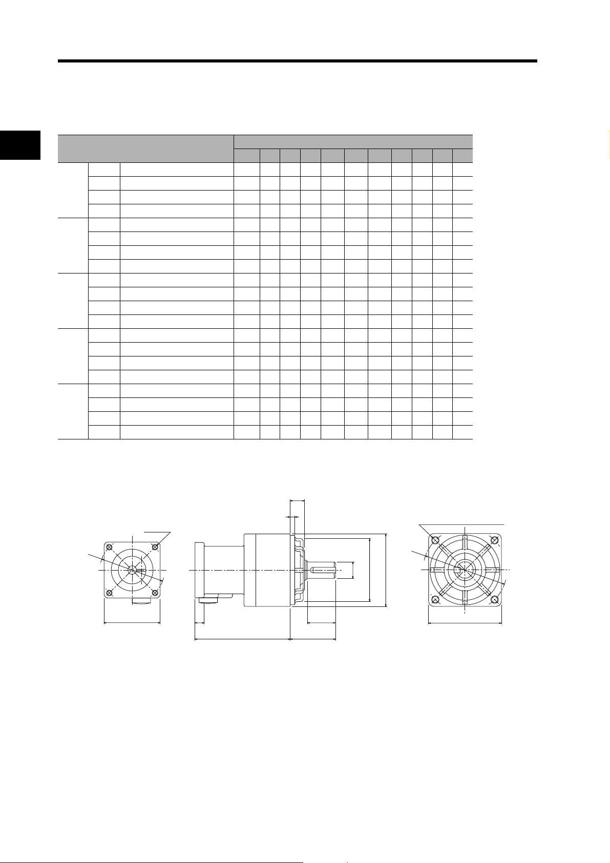
2-2 External and Mounting Hole Dimensions
Four, Z2 (effective depth: L)
C2 × C2
C1 × C1
D1 dia.
E3
F
LM
GT
LR
D3 dia., h: 7
D4 dia.
S dia., h: 6
Four, Z1
D2 dia.
Backlash = 15' Max.
Decelerators for 3,000-r/min Servomotors
2
Model
1/5 R88G-VRSF05B100CJ 67.5 32405246605045103 6
50 W
1/9 R88G-VRSF09B100CJ 67.5 32405246605045103 6
1/15 R88G-VRSF15B100CJ 78.0 32405246605045103 6
1/25 R88G-VRSF25B050CJ 78.0 32405246605045103 6
1/5 R88G-VRSF05B100CJ 67.5 32405246605045103 6
100 W
1/9 R88G-VRSF09B100CJ 67.5 32405246605045103 6
1/15 R88G-VRSF15B100CJ 78.0 32405246605045103 6
1/25 R88G-VRSF25B100CJ 78.0 32405246605045103 6
1/5 R88G-VRSF05B200CJ 72.5 32605270605045103 10
200 W
1/9 R88G-VRSF09C200CJ 89.5 50 60 78 70 90 70 62 17 38
1/15 R88G-VRSF15C200CJ 100.0 50 60 78 70 90 70 62 17 38
1/25 R88G-VRSF25C200CJ 100.0 50 60 78 70 90 70 62 17 38
1/5 R88G-VRSF05C400CJ 89.5 50 60 78 70 90 70 62 17 38
400 W
1/9 R88G-VRSF09C400CJ 89.5 50 60 78 70 90 70 62 17 38
1/15 R88G-VRSF15C400CJ 100.0 50 60 78 70 90 70 62 17 38
1/25 R88G-VRSF25C400CJ 100.0 50 60 78 70 90 70 62 17 38
1/5 R88G-VRSF05C750CJ 93.5 50 8078 90 90 70 62 17 3 10
Standard Models and Dimensions
750 W
1/9 R88G-VRSF09D750CJ 97.5 61 8098 90 115 90 75 18 510
1/15 R88G-VRSF15D750CJ 110.0 61 8098 90 115 90 75 18 510
1/25 R88G-VRSF25D750CJ 110.0 61 8098 90 115 90 75 18 510
Note The standard models have a straight shaft with a key.
Dimensions (mm)
LM LR C1 C2 D1 D2 D3 D4 E3 F G
Outline Drawings
2-57
Page 91

50 W
100 W
200 W
400 W
750 W
2-2 External and Mounting Hole Dimensions
Dimensions (mm)
Model
1/5 R88G-VRSF05B100CJ 12 20 M4 M5 M3 12 16 4 4 2.5
1/9 R88G-VRSF09B100CJ 12 20 M4 M5 M3 12 16 4 4 2.5
1/15 R88G-VRSF15B100CJ 12 20 M4 M5 M3 12 16 4 4 2.5
1/25 R88G-VRSF25B050CJ 12 20 M4 M5 M3 12 16 4 4 2.5
1/5 R88G-VRSF05B100CJ 12 20 M4 M5 M3 12 16 4 4 2.5
1/9 R88G-VRSF09B100CJ 12 20 M4 M5 M3 12 16 4 4 2.5
1/15 R88G-VRSF15B100CJ 12 20 M4 M5 M3 12 16 4 4 2.5
1/25 R88G-VRSF25B100CJ 12 20 M4 M5 M3 12 16 4 4 2.5
1/5 R88G-VRSF05B200CJ 12 20 M4 M5 M4 12 16 4 4 2.5
1/9 R88G-VRSF09C200CJ 19 30M4M6M42022 6 6 3.5
1/15 R88G-VRSF15C200CJ 19 30M4M6M42022 6 6 3.5
1/25 R88G-VRSF25C200CJ 19 30M4M6M42022 6 6 3.5
1/5 R88G-VRSF05C400CJ 19 30M4M6M42022 6 6 3.5
1/9 R88G-VRSF09C400CJ 19 30M4M6M42022 6 6 3.5
1/15 R88G-VRSF15C400CJ 19 30M4M6M42022 6 6 3.5
1/25 R88G-VRSF25C400CJ 19 30M4M6M42022 6 6 3.5
1/5 R88G-VRSF05C750CJ 19 30M5M6M42022 6 6 3.5
1/9 R88G-VRSF09D750CJ 24 40 M5 M8 M4 20 30 8 74
1/15 R88G-VRSF15D750CJ 24 40 M5 M8 M4 20 30 8 74
1/25 R88G-VRSF25D750CJ 24 40 M5 M8 M4 20 30 8 74
S T Z1 Z2 AT L
Key dimensions
QK b h t1
2
Outline Drawings
Set bolt (AT)
Key Dimensions
QK
Standard Models and Dimensions
b
t1
h
2-58
Page 92
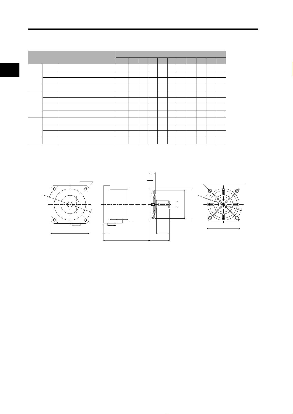
2-2 External and Mounting Hole Dimensions
Four, Z1
E3
F
C1 × C1
LM
GT
LR
D3 dia., h: 7
D4 dia.
S dia., h: 6
Four, Z2 (effective depth: L)
C2 × C2
D2 dia.
D1 dia.
Decelerators for 3,000-r/min Flat Servomotors
Model
2
100 W
1/5 R88G-VRSF05B100PCJ 67.5 3260527060504510 38
1/9 R88G-VRSF09B100PCJ 67.5 3260527060504510 38
1/15 R88G-VRSF15B100PCJ 78.0 3260527060504510 38
LM LR C1 C2 D1 D2 D3 D4 E3 F G
Dimensions (mm)
1/25 R88G-VRSF25B100PCJ 78.0 3260527060504510 38
1/5 R88G-VRSF05B200PCJ 72.5 32 80529060504510 3 12
200 W
1/9 R88G-VRSF09C200PCJ 89.5 50 8078 90 90 70 62 17 3 12
1/15 R88G-VRSF15C200PCJ 100.0 50 8078 90 90 70 62 17 3 12
1/25 R88G-VRSF25C200PCJ 100.0 50 8078 90 90 70 62 17 3 12
1/5 R88G-VRSF05C400PCJ 89.5 50 8078 90 90 70 62 17 3 12
400 W
1/9 R88G-VRSF09C400PCJ 89.5 50 8078 90 90 70 62 17 3 12
1/15 R88G-VRSF15C400PCJ 100.0 50 8078 90 90 70 62 17 3 12
1/25 R88G-VRSF25C400PCJ 100.0 50 8078 90 90 70 62 17 3 12
Note The standard models have a straight shaft with a key.
Outline Drawings
Standard Models and Dimensions
2-59
Page 93
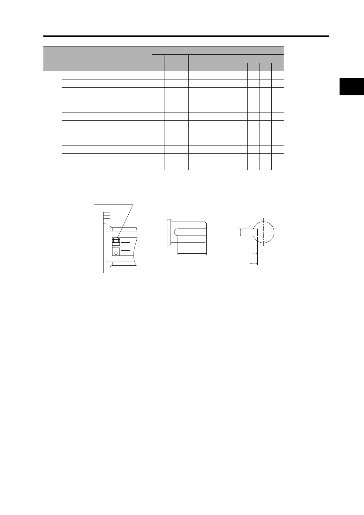
1/5 R88G-VRSF05B100PCJ 12 20 M4 M5 M3 12 16 4 4 2.5
Set bolt (AT)
QK
h
t1
b
Key Dimensions
100 W
200 W
400 W
1/9 R88G-VRSF09B100PCJ 12 20 M4 M5 M3 12 16 4 4 2.5
1/15 R88G-VRSF15B100PCJ 12 20 M4 M5 M3 12 16 4 4 2.5
1/25 R88G-VRSF25B100PCJ 12 20 M4 M5 M3 12 16 4 4 2.5
1/5 R88G-VRSF05B200PCJ 12 20 M5 M5 M4 12 16 4 4 2.5
1/9 R88G-VRSF09C200PCJ 19 30M5 M6 M4 2022 6 6 3.5
1/15 R88G-VRSF15C200PCJ 19 30M5 M6 M4 20 22 6 6 3.5
1/25 R88G-VRSF25C200PCJ 19 30M5 M6 M4 20 22 6 6 3.5
1/5 R88G-VRSF05C400PCJ 19 30M5 M6 M4 2022 6 6 3.5
1/9 R88G-VRSF09C400PCJ 19 30M5 M6 M4 2022 6 6 3.5
1/15 R88G-VRSF15C400PCJ 19 30M5 M6 M4 20 22 6 6 3.5
1/25 R88G-VRSF25C400PCJ 19 30M5 M6 M4 20 22 6 6 3.5
Outline Drawings
Model
2-2 External and Mounting Hole Dimensions
Dimensions (mm)
S T Z1 Z2 AT L
Key dimensions
QK b h t1
2
Standard Models and Dimensions
2-60
Page 94
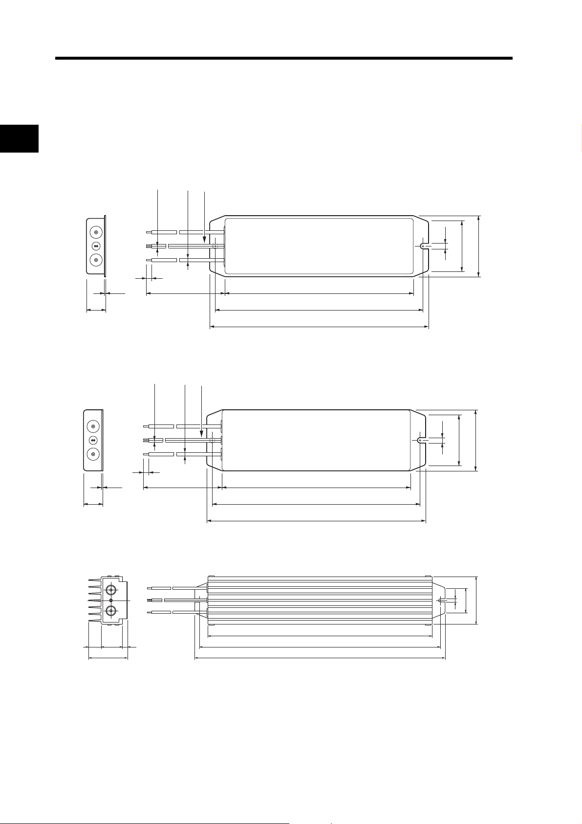
2-2 External and Mounting Hole Dimensions
20
t1.2 104
122
130
43.5
28
4.2
6
Thermal switch output
500
1.5 dia.
(0.3mm
2
)
3 dia.
(0.75mm
2
)
20
t1.2 200
220
230
62
48
4.2
6
500
Thermal switch output
1.5 dia.
(0.3mm
2
)
3 dia.
(0.75mm
2
)
External Regeneration Resistor Dimensions
2
External Regeneration Resistor
R88A-RR08050S/-RR080100S
R88A-RR22047S
Standard Models and Dimensions
R88A-RR50020S
4325 10
78
2-61
360
386
402
5.2
40
76
Page 95
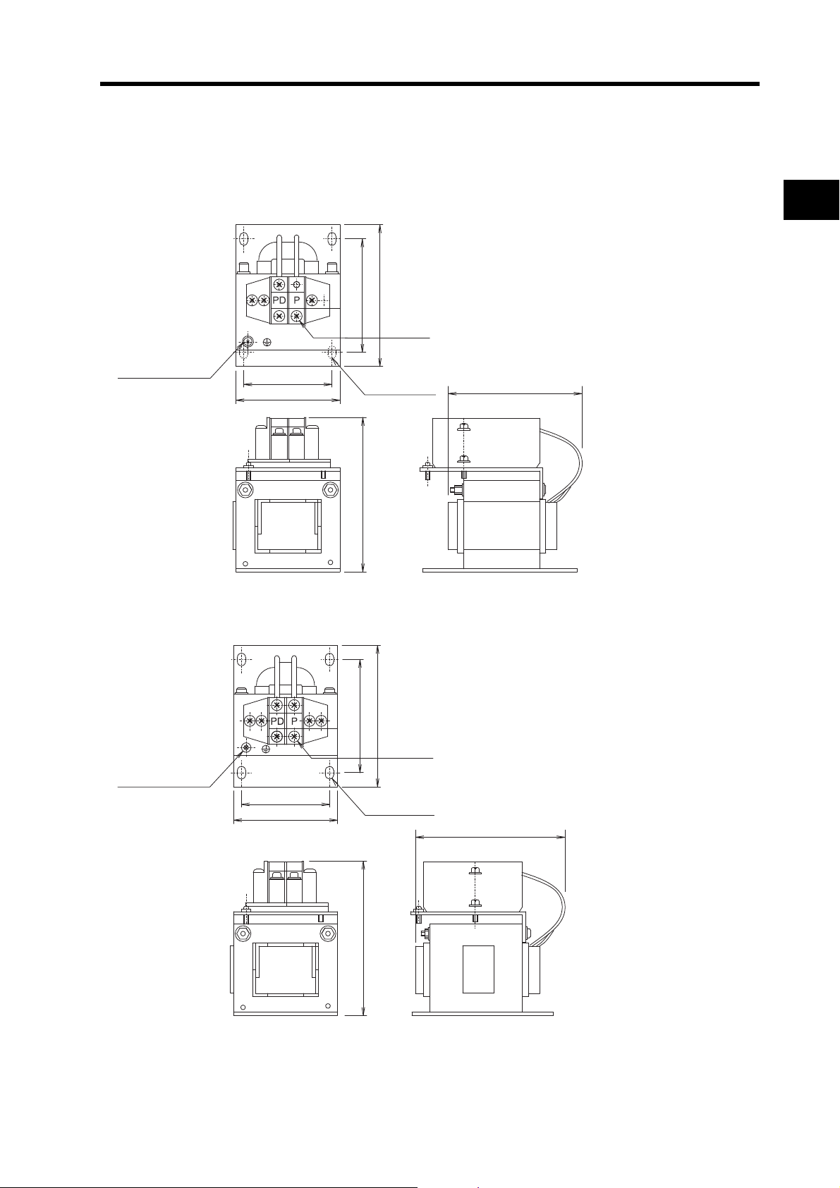
Reactor Dimensions
Ground terminal
(M4)
66
56
72
90
Four, 5.2 × 8
Two, M4
98
85
66
56
72
90
98
95
Ground terminal
(M4)
Two, M4
Four, 5.2 × 8
2-2 External and Mounting Hole Dimensions
3G3AX-DL2002
2
Standard Models and Dimensions
3G3AX-DL2004
2-62
Page 96

2-2 External and Mounting Hole Dimensions
66
56
72
90
98
105
Ground terminal
(M4)
Two, M4
Four, 5.2 × 8
66
56
72
90
98
115
Ground terminal
(M4)
Two, M4
Four, 5.2 × 8
3G3AX-DL2007
2
Standard Models and Dimensions
3G3AX-DL2015
2-63
Page 97

3G3AX-DL2022
86
71
80
100
Four, 6 × 9
116
105
Ground terminal
(M4)
Two, M4
Ground terminal (M5)
Six, M4
terminal screws
Terminal
block
150
92
C
4060
A
Ro R So S To T
Connection Diagram
Y±1
50±1
Ro R So S To
T
9.5
Four, 6 dia.
(Notch)
2-2 External and Mounting Hole Dimensions
2
3G3AX-AL2025/-AL2055
3G3AX-AL2025 130 8267
3G3AX-AL2055 140 98 75
Model
Standard Models and Dimensions
Dimensions (mm)
A C Y
2-64
Page 98

2-2 External and Mounting Hole Dimensions
3G3AX-AL2110/-AL2220
Terminal holes:
Six, K dia.
2
Ro R So S To T
A
H
55D
Four, 6 dia.
(Notch)
Model
3G3AX-AL2110 160 103 70 170 106 60 805.3 12
Standard Models and Dimensions
3G3AX-AL2220 180113 75 190 13690 908.4 16.5
A C D H H1 X Y K W
Y±1X±1
C
Ground terminal (M6)
Dimensions (mm)
H1
Ro RSo S To T
Connection Diagram
W
W=Terminal width
2-65
Page 99

Chapter 3
Specifications
3-1 Servo Drive Specifications................................. 3-1
General Specifications..........................................................3-1
Characteristics......................................................................3-2
Main Circuit and Servomotor Connector Specifications........3-7
Control I/O Connector Specifications (CN1) .........................3-10
Control Input Circuits ............................................................3-14
Control Output Circuits..........................................................3-14
Control Sequence Timing .....................................................3-15
Encoder Connector Specifications (CN2) .............................3-16
Parameter Unit Connector Specifications (CN3) ..................3-16
3-2 Servomotor Specifications ................................. 3-17
General Specifications..........................................................3-17
Characteristics......................................................................3-18
Encoder Specifications .........................................................3-31
3-3 Decelerator Specifications ................................. 3-32
Standard Models and Specifications.....................................3-32
3-4 Cable and Connector Specifications..................3-42
Encoder Cable Specifications...............................................3-42
Absolute Encoder Battery Cable Specifications....................3-48
Servomotor Power Cable Specifications...............................3-49
Communications Cable Specifications..................................3-67
Connector Specifications......................................................3-68
MECHATROLINK-II Communications Cable
Specifications........................................................................3-71
Control Cable Specifications.................................................3-73
3-5 Parameter Unit Specifications...........................3-78
3-6 External Regeneration Resistor
Specifications....................................................3-79
External Regeneration Resistor Specifications.....................3-79
3-7 Reactor Specifications ......................................3-80
Page 100

3-1 Servo Drive Specifications
3-1 Servo Drive Specifications
3
General Specifications
Ambient operating temperature
and humidity
Ambient storage temperature
and humidity
Specifications
Operating and storage
atmosphere
Vibration resistance
Impact resistance Acceleration of 19.6m/s
Insulation resistance
Dielectric strength
Protective structure Built into panel (IP10).
International
standards
Select the Servo Drive matching the Servomotor to be used. (For details, refer to Servo Drive-
Servomotor Combinations on page 2-5.)
OMNUC G-series Servo Drives are designed specifically for use with MECHATROLINK-II
communication.
Item Specifications
0 to 55°C, 90% RH max. (with no condensation)
−20 to 65°C, 90% RH max. (with no condensation)
No corrosive gases
Smaller of either 10 to 60 Hz with double amplitude of 0.1 mm or acceleration of
5.88 m/s
Between power supply/power line terminals and frame ground: 0.5 MΩ min.
(at 500 VDC)
Between power supply/power line terminals and frame ground: 1,500 VAC for 1 min
at 50/60 Hz
Between each control signal and frame ground: 500 VAC for 1 min
EMC
EC
Directives
UL standards UL 508C
CSA standards CSA 22.2 No.14
Directive
Low
Voltage
Directive
EN 55011 Class A Group 1
EN 61000-6-2, IEC 61000-4-2/-3/-4/-5/-6/-11
EN 50178
2
max. in X, Y, and Z directions.
2
max. 2 times each in X, Y, and Z directions
Note1. The above items reflect individual evaluation testing. The results may differ under compound conditions.
Note2. Never perform withstand-voltage or other megameter tests on the Servo Drive. Doing so may damage the
internal elements.
Note3. Depending on the operating conditions, some Servo Drive parts will require maintenance. For details,
refer to Periodic Maintenance on page 8-21.
Note4. The service life of the Servo Drive is 28,000 hours at an average ambient temperature of 55
of the rated torque.
°C at 100%
3-1
 Loading...