

Page 1
Industrial PC Platform
NY-series
Industrial Monitor
User's Manual
NYM15W
NYM15W
NYM12W
NYM12W-C106£
-C100£
-C106£
-C100£
Industrial Monitor
W554-E2-03
Page 2

NOTE
All rights reserved. No part of this publication may be reproduced, stored in a retrieval system, or
transmitted, in any form, or by any means, mechanical, electronic, photocopying, recording, or other-
wise, without the prior written permission of OMRON.
No patent liability is assumed with respect to the use of the information contained herein. Moreover
because OMRON is constantly striving to improve its high-quality products, the information contained
in this manual is subject to change without notice. Every precaution has been taken in the preparation
of this manual. Nevertheless, OMRON assumes no responsibility for errors or omissions. Neither is
any liability assumed for damages resulting from the use of the information contained in this publica-
tion.
,
Trademarks
• Sysmac and SYSMAC are trademarks or registered trademarks of OMRON Corporation in Japan
and other countries for OMRON factory automation products.
• Windows is a registered trademark of Microsoft Corporation in the USA and other countries.
Other company names and product names in this document are the trademarks or registered trade-
marks of their respective companies.
Copyrights
Microsoft product screen shots reprinted with permission from Microsoft Corporation.
Page 3
Introduction
Thank you for purchasing the Industrial Monitor.
This manual contains information that is necessary to use the Industrial Monitor (hereafter also named
as Monitor). Please read this manual and make sure you understand the functionality and perform-
ance of the Monitor before attempting to use it.
Keep this manual in a safe place where it will be available for reference during operation.
Intended Audience
This manual is intended for the following personnel, who must also have knowledge of electrical sys-
tems (an electrical engineer or the equivalent).
• Personnel in charge of introducing Factory Automation systems.
• Personnel in charge of designing Factory Automation systems.
• Personnel in charge of installing and maintaining Factory Automation systems.
• Personnel in charge of managing Factory Automation systems and facilities.
Introduction
Applicable Products
This manual covers the following Industrial Monitor products:
Industrial Monitor, 15.4 inch
Industrial Monitor, 12.1 inch
Additional Information
Refer to 1-4 Product Configuration on page
Product Model
NYM15W-C100£
NYM15W-C106£
NYM12W-C100£
NYM12W-C106£
1 - 5 for configuration details.
NY-series Industrial Monitor User's Manual (W554)
1
Page 4

CONTENTS
CONTENTS
Introduction .............................................................................................................. 1
Intended Audience
Applicable Products ......................................................................................................................................... 1
Manual Information.................................................................................................. 7
Page Structure.................................................................................................................................................7
Special Information .......................................................................................................................................... 8
Terms and Conditions Agreement.......................................................................... 9
Warranty and Limitations of Liability ................................................................................................................ 9
Application Considerations ............................................................................................................................10
Disclaimers ....................................................................................................................................................10
Safety Precautions................................................................................................. 11
Definition of Precautionary Information.......................................................................................................... 11
Symbols ......................................................................................................................................................... 11
Warnings........................................................................................................................................................ 12
Cautions......................................................................................................................................................... 13
...........................................................................................................................................1
Precautions for Safe Use ...................................................................................... 14
Disassembly, Dropping, Mounting, Installation and Storage .........................................................................14
Wiring............................................................................................................................................................. 14
Power Supply Design and Turning ON/OFF the Power Supply.....................................................................15
Operation ....................................................................................................................................................... 15
Cleaning, Maintenance and Disposal ............................................................................................................16
Precautions for Correct Use ................................................................................. 17
Storage, Installation and Mounting ................................................................................................................17
Wiring............................................................................................................................................................. 17
Actual Operation and Operation ....................................................................................................................17
Cleaning and Maintenance ............................................................................................................................ 18
Regulations and Standards .................................................................................. 19
Conformance to EU Directives ......................................................................................................................19
Conformance to KC Standards......................................................................................................................20
Conformance to UL and CSA Standards.......................................................................................................20
Related Manuals..................................................................................................... 21
Related Industrial PC Manuals ......................................................................................................................21
Related Industrial PC Without Operating System Manuals ...........................................................................21
Related IPC Machine Controller Manuals...................................................................................................... 22
Related IPC RTOS Controller Manuals .........................................................................................................23
Related IPC Programmable Multi Axis Controller Manuals ...........................................................................23
Terminology and Abbreviations ........................................................................... 24
Industrial PC Platform ...................................................................................................................................24
Hardware ......................................................................................................................................................24
Software......................................................................................................................................................... 24
Revision History..................................................................................................... 25
Sections in this Manual ......................................................................................... 27
2
NY-series Industrial Monitor User's Manual (W554)
Page 5

Section 1 Overview
1-1 Intended Use ........................................................................................................................1 - 2
1-2
Hardware Features...............................................................................................................1 - 3
1-3 ID Information Label ............................................................................................................1 - 4
1-4 Product Configuration.........................................................................................................1 - 5
1-5 Industrial PC Platform Overview ........................................................................................1 - 6
1-5-1 Industrial Monitor ......................................................................................................................1 - 6
1-5-2 Industrial Box PC .....................................................................................................................1 - 7
1-5-3 Industrial Panel PC ..................................................................................................................1 - 7
Section 2 Hardware
2-1 Component Names and Functions.....................................................................................2 - 2
2-1-1
2-1-2 Bottom of the Industrial Monitor ................................................................................................2 - 3
2-2 LED Indicators......................................................................................................................2 - 4
2-2-1 Logo LED ..................................................................................................................................2 - 5
2-2-2 Status LED Indicator .................................................................................................................2 - 5
2-3 Connectors ........................................................................................................................... 2 - 6
2-3-1 Power Connector ......................................................................................................................2 - 6
2-3-2 DVI-D Connector (Optional) ......................................................................................................2 - 7
2-3-3 NY Monitor Link Connector (Optional) ......................................................................................2 - 7
2-3-4 USB Type-A Connector.............................................................................................................2 - 8
2-3-5 USB Type-B Connector (Optional)............................................................................................2 - 9
2-4 Optional Hardware ............................................................................................................. 2 - 10
2-4-1 DVI Cables ..............................................................................................................................2 - 10
2-4-2 USB Type-A to USB Type-B Cables .......................................................................................2 - 11
2-4-3 NY Monitor Link Cables ..........................................................................................................2 - 12
2-4-4 Power Supply ..........................................................................................................................2 - 13
Front and Top of the Industrial Monitor .....................................................................................2 - 2
CONTENTS
Section 3 Software
3-1 Operating Systems ..............................................................................................................3 - 2
3-1-1 Touch Functionality ...................................................................................................................3 - 2
3-1-2 Determine Your Version of the Windows Operating Systems ...................................................3 - 3
3-2 Support Software ................................................................................................................. 3 - 4
3-2-1 Overview IPC Support Software for Windows...........................................................................3 - 4
3-2-2 Industrial Monitor Utility ............................................................................................................3 - 5
3-2-3 Industrial Monitor Brightness Utility ..........................................................................................3 - 8
3-2-4 Industrial PC Tray Utility .........................................................................................................3 - 10
3-3 Software for Developers....................................................................................................3 - 13
3-3-1 Overview IPC Developer Software for Windows.....................................................................3 - 13
3-3-2 Industrial Monitor API .............................................................................................................3 - 14
Section 4 Specifications
4-1 General Specifications .......................................................................................................4 - 2
4-1-1
4-1-2 General Electrical Specifications...............................................................................................4 - 3
4-2 Connector Specifications ...................................................................................................4 - 4
4-2-1 Power Connector Specifications ...............................................................................................4 - 4
4-2-2 DVI-D Connector Specifications................................................................................................4 - 5
Dimensions and Weight ............................................................................................................4 - 2
NY-series Industrial Monitor User's Manual (W554)
3
Page 6

CONTENTS
4-2-3 NY Monitor Link Connector Specifications................................................................................4 - 7
4-2-4
4-2-5 USB Type-B Connector Specifications....................................................................................4 - 10
USB Type-A Connector Specifications......................................................................................4 - 9
4-3 Display Specifications....................................................................................................... 4 - 11
4-4 Environmental Specifications...........................................................................................4 - 12
4-4-1 Operation Environment Specifications ....................................................................................4 - 12
4-4-2 Temperature and Humidity Specifications...............................................................................4 - 13
4-4-3 Recycling Specifications .........................................................................................................4 - 14
Section 5 Installation
5-1 Unpack .................................................................................................................................. 5 - 2
5-1-1
5-1-2 Items Supplied ..........................................................................................................................5 - 3
5-2 Mount ....................................................................................................................................5 - 4
5-2-1 Installation Method in Control Panels........................................................................................5 - 4
5-2-2 Product Orientation ...................................................................................................................5 - 5
5-2-3 Temperature ..............................................................................................................................5 - 6
5-2-4 Humidity ....................................................................................................................................5 - 8
5-2-5 Vibration and Shock ..................................................................................................................5 - 8
5-2-6 Atmosphere...............................................................................................................................5 - 9
5-2-7 Electrical Environment ..............................................................................................................5 - 9
5-2-8 Prepare the Mounting Surface ................................................................................................5 - 14
5-2-9 Mount the Industrial Monitor....................................................................................................5 - 16
5-3 Wire .....................................................................................................................................5 - 17
5-3-1 Ground ....................................................................................................................................5 - 17
5-3-2 Wire the Power Connector ......................................................................................................5 - 24
5-4 Connect...............................................................................................................................5 - 26
5-4-1 Connector Identification ..........................................................................................................5 - 26
5-4-2 Connection Procedure ............................................................................................................5 - 27
5-5 Initial Power ON .................................................................................................................5 - 28
5-5-1 Initial Power ON Procedure.....................................................................................................5 - 28
Unpack Procedure ....................................................................................................................5 - 2
Section 6 Operating Procedures
6-1 Touchscreen Operation.......................................................................................................6 - 2
6-2
Power ON / Power OFF / Standby.......................................................................................6 - 3
6-3 Support Software and Product Information .....................................................................6 - 4
6-4 React to Product Messages ................................................................................................ 6 - 5
Section 7 Maintenance
7-1 Preventive Maintenance ...................................................................................................... 7 - 2
7-1-1 Preventive Maintenance Schedule............................................................................................7 - 2
7-1-2 Clean the Touchscreen Surface ................................................................................................7 - 3
7-1-3 Clean the Monitor......................................................................................................................7 - 3
7-1-4 Check the Gasket Seal .............................................................................................................7 - 4
7-1-5 Keep Software Updated ............................................................................................................7 - 4
7-2 Corrective Maintenance ......................................................................................................7 - 5
7-2-1 Warning and Error Messages....................................................................................................7 - 5
7-2-2 Windows Event Viewer..............................................................................................................7 - 5
7-2-3 Correct Display Functionality when Nothing is Displayed .........................................................7 - 8
7-2-4 Correct Touchscreen Functionality............................................................................................7 - 9
4
NY-series Industrial Monitor User's Manual (W554)
Page 7

Index
CONTENTS
NY-series Industrial Monitor User's Manual (W554)
5
Page 8

CONTENTS
6
NY-series Industrial Monitor User's Manual (W554)
Page 9
Manual Information
A
B
C
E
F
B
C
H
5 Installation
5 - 3
N
Y-series User's Manual (W555)
5-1 Unpack
5
5-1-1 Unpack Procedure
G
5-1
Unpack
This section provides details on how to unpack the Industrial Panel PC.
5-1-1
Unpack Procedure
1 Check the package for damage.
If there is any visible damage:
• Take photos of the package and save them.
• Inform your supplier immediately.
2 Open the package.
Ensure not to damage the contents.
3 Ensure that all items are present.
Additional Information
Refer to 5-1-2 Items Supplied with the Product
for the items supplied.
This section provides information about this manual.
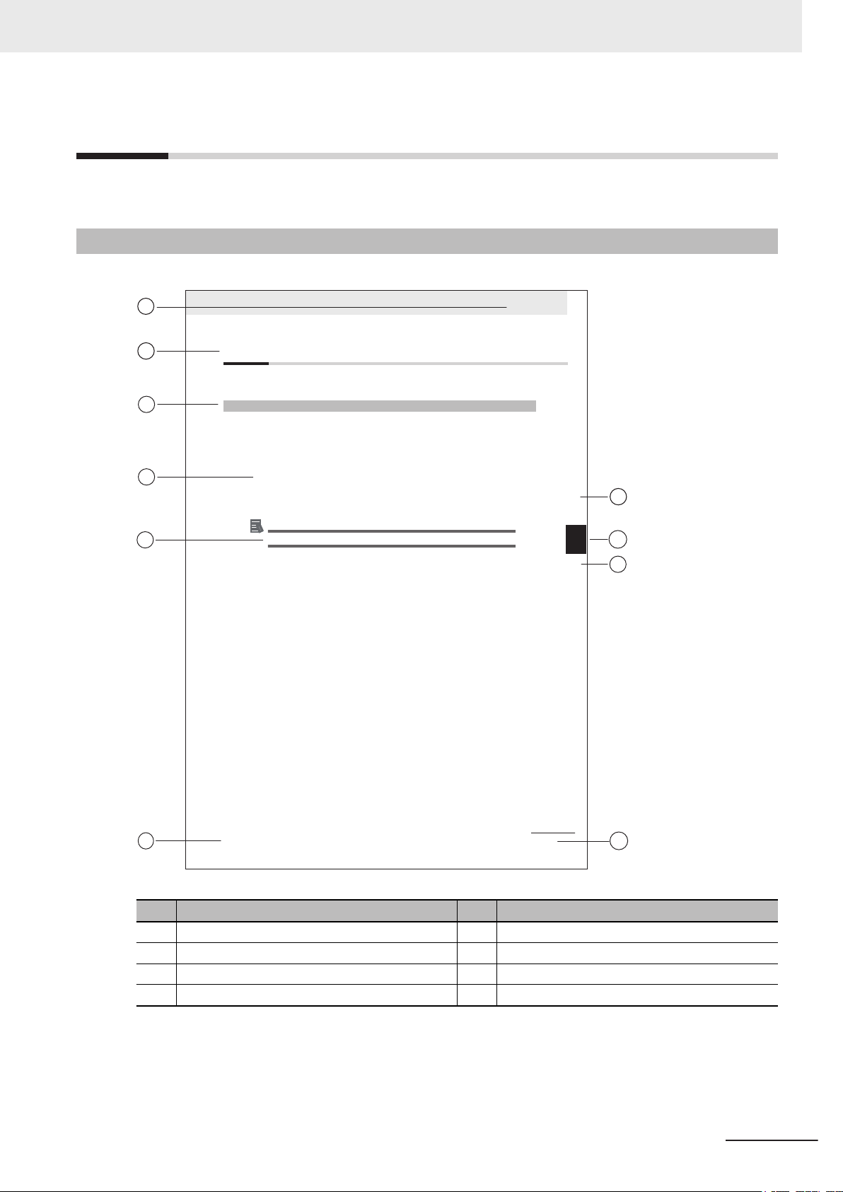
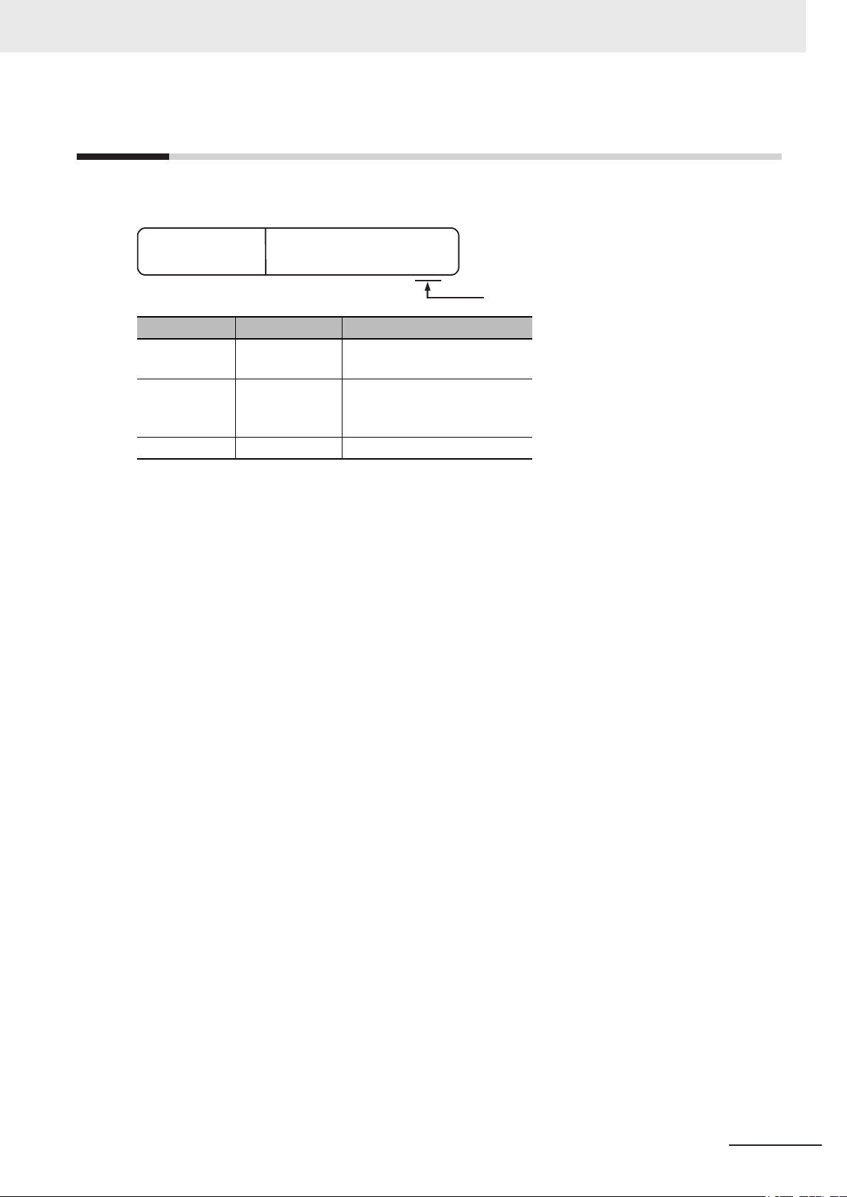
Page Structure
The following page structure is used in this manual.
Manual Information
Note: This illustration is provided as a sample. It will not literally appear in this manual.
Item Explanation Item Explanation
A Level 1 heading E Special Information
B Level 2 heading F Manual name
C Level 3 heading G Page tab with the number of the main section
D Step in a procedure H Page number
NY-series Industrial Monitor User's Manual (W554)
7
Page 10
Manual Information
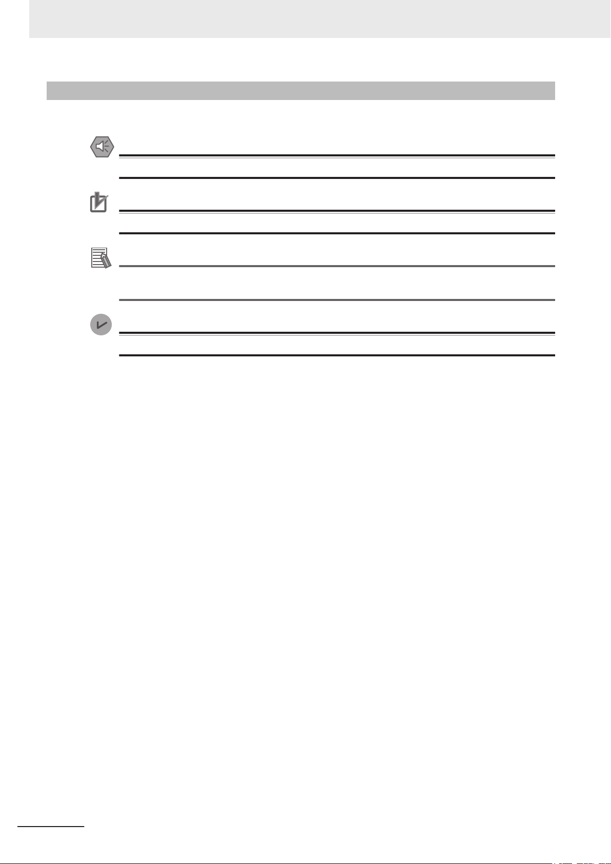
Special Information
Special information in this manual is classified as follows:
Precautions for Safe Use
Precautions on what to do and what not to do to ensure safe usage of the product.
Precautions for Correct Use
Precautions on what to do and what not to do to ensure proper operation and performance.
Additional Information
Additional information to read as required.
This information is provided to increase understanding or make operation easier
Version Information
.
Information on differences in specifications and functionality between different versions.
8
NY-series Industrial Monitor User's Manual (W554)
Page 11

Terms and Conditions Agreement
Terms and Conditions Agreement
Warranty and Limitations of Liability
Warranty
• Exclusive Warranty
Omron’s exclusive warranty is that the Products will be free from defects in materials and workman-
ship for a period of twelve months from the date of sale by Omron (or such other period expressed
in writing by Omron). Omron disclaims all other warranties, expressed or implied.
• Limitations
OMRON MAKES NO WARRANTY OR REPRESENTATION, EXPRESS OR IMPLIED, ABOUT
NON-INFRINGEMENT, MERCHANTABILITY OR FITNESS FOR A PARTICULAR PURPOSE OF
THE PRODUCTS. BUYER ACKNOWLEDGES THAT IT ALONE HAS DETERMINED THAT THE
PRODUCTS WILL SUITABLY MEET THE REQUIREMENTS OF THEIR INTENDED USE.
Omron further disclaims all warranties and responsibility of any type for claims or expenses based
on infringement by the Products or otherwise of any intellectual property right.
• Buyer Remedy
Omron’s sole obligation hereunder shall be, at Omron’s election, to (i) replace (in the form originally
shipped with Buyer responsible for labor charges for removal or replacement thereof) the non-com-
plying Product, (ii) repair the non-complying Product, or (iii) repay or credit Buyer an amount equal
to the purchase price of the non-complying Product; provided that in no event shall Omron be re-
sponsible for warranty, repair, indemnity or any other claims or expenses regarding the Products un-
less Omron’s analysis confirms that the Products were properly handled, stored, installed and main-
tained and not subject to contamination, abuse, misuse or inappropriate modification. Return of any
Products by Buyer must be approved in writing by Omron before shipment. Omron Companies shall
not be liable for the suitability or unsuitability or the results from the use of Products in combination
with any electrical or electronic components, circuits, system assemblies or any other materials or
substances or environments. Any advice, recommendations or information given orally or in writing,
are not to be construed as an amendment or addition to the above warranty.
See http://www.omron.com/global/ or contact your Omron representative for published information.
Limitations of Liability
OMRON COMPANIES SHALL NOT BE LIABLE FOR SPECIAL, INDIRECT, INCIDENTAL, OR CON-
SEQUENTIAL DAMAGES, LOSS OF PROFITS OR PRODUCTION OR COMMERCIAL LOSS IN ANY
WAY CONNECTED WITH THE PRODUCTS, WHETHER SUCH CLAIM IS BASED IN CONTRACT,
WARRANTY, NEGLIGENCE OR STRICT LIABILITY. Further, in no event shall liability of Omron Com-
panies exceed the individual price of the Product on which liability is asserted.
NY-series Industrial Monitor User's Manual (W554)
9
Page 12

Terms and Conditions Agreement
Application Considerations
Suitability for Use
Omron Companies shall not be responsible for conformity with any standards, codes or regulations
which apply to the combination of the Product in the Buyer
er’s request, Omron will provide applicable third party certification documents identifying ratings and
limitations of use which apply to the Product. This information by itself is not sufficient for a complete
determination of the suitability of the Product in combination with the end product, machine, system, or
other application or use. Buyer shall be solely responsible for determining appropriateness of the par-
ticular Product with respect to Buyer’s application, product or system. Buyer shall take application re-
sponsibility in all cases.
NEVER USE THE PRODUCT FOR AN APPLICATION INVOLVING SERIOUS RISK TO LIFE OR
PROPERTY WITHOUT ENSURING THAT THE SYSTEM AS A WHOLE HAS BEEN DESIGNED TO
ADDRESS THE RISKS, AND THAT THE OMRON PRODUCT(S) IS PROPERLY RATED AND IN-
STALLED FOR THE INTENDED USE WITHIN THE OVERALL EQUIPMENT OR SYSTEM.
’s application or use of the Product. At Buy-
Disclaimers
Performance Data
Data presented in Omron Company websites, catalogs and other materials is provided as a guide for
the user in determining suitability and does not constitute a warranty
Omron’s test conditions, and the user must correlate it to actual application requirements. Actual per-
formance is subject to the Omron’s Warranty and Limitations of Liability.
Change in Specifications
Product specifications and accessories may be changed at any time based on improvements and oth-
er reasons. It is our practice to change part numbers when published ratings or features are changed,
or when significant construction changes are made. However
be changed without any notice. When in doubt, special part numbers may be assigned to fix or estab-
lish key specifications for your application. Please consult with your Omron’s representative at any
time to confirm actual specifications of purchased Product.
. It may represent the result of
, some specifications of the Product may
10
Errors and Omissions
Information presented by Omron Companies has been checked and is believed to be accurate; how-
ever
, no responsibility is assumed for clerical, typographical or proofreading errors or omissions.
NY-series Industrial Monitor User's Manual (W554)
Page 13
Safety Precautions
Definition of Precautionary Information
The following notation is used in this manual to provide precautions required to ensure safe usage of
the Industrial Monitor. The safety precautions that are provided are extremely important to safety.
Always read and heed the information provided in all safety precautions.
The following notation is used.
Indicates a potentially hazardous situation which, if not avoid-
WARNING
Caution
ed, could result in death or serious injury
may be severe property damage.
Indicates a potentially hazardous situation which, if not avoid-
ed, may result in minor or moderate injury
Safety Precautions
. Additionally, there
, or property damage.
Symbols
The circle and slash symbol indicates operations that you must not do. The
specific operation is shown in the circle and explained in text.
This example indicates prohibiting disassembly
The triangle symbol indicates precautions (including warnings). The specific
operation is shown in the triangle and explained in text.
This example indicates a precaution for electric shock.
The triangle symbol indicates precautions (including warnings). The specific
operation is shown in the triangle and explained in text.
This example indicates a general precaution.
The filled circle symbol indicates operations that you must do. The specific
operation is shown in the circle and explained in text.
This example shows a general precaution for something that you must do.
.
NY-series Industrial Monitor User's Manual (W554)
11
Page 14

Safety Precautions
Warnings
Ensure that installation and post-installation checks are performed by personnel in charge who possess a thorough understanding of the machinery
to be installed.
Do not use the input functions of the touchscreen in applications that involve
human life, in applications that may result in serious injury
stop switches.
Water or other liquid present on the touchscreen surface may create false
touch behavior and unexpected operation. Wipe away liquid on the
touchscreen before operation.
Disassembly and Dropping
WARNING
, or for emergency
Do not attempt to disassemble, repair, or modify the product in any way. Doing so may result in malfunction or fire.
Installation
Always connect to a ground of 100 Ω or less when installing the product.
12
NY-series Industrial Monitor User's Manual (W554)
Page 15
Cautions
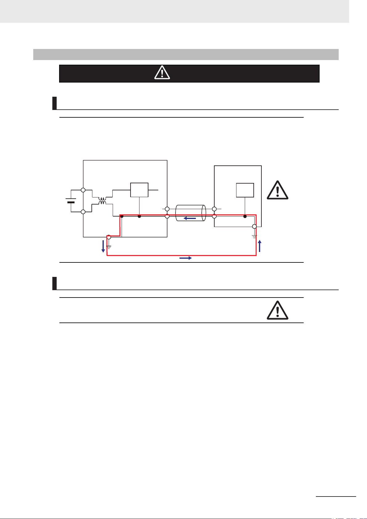
Industrial PC Platform Product
Non-isolated
Device
Non-isolated
Interface
24 VDC
0 VDC
Wiring
The product has an internal non-isolated DC power supply. Circuit ground (0
VDC) and frame ground are connected together. When connecting a nonisolated device or a non-isolated interface to the product, take appropriate
actions to avoid communication failures or damage to the mentioned ports.
Safety Precautions
Caution
Operation
When using a system with multiple touchscreens, multiple users can perform simultaneous operations. Make sure that this can not result in unintended actions.
NY-series Industrial Monitor User's Manual (W554)
13
Page 16

Precautions for Safe Use
Precautions for Safe Use
Disassembly, Dropping, Mounting, Installation and Storage
• Do not drop the product or subject it to abnormal vibration or shock. Doing so may result in product
malfunction or burning.
• When unpacking, check carefully for any external scratches or other damages. Also, shake the
product gently and check for any abnormal sound.
• Always use the devices specified in the relevant manual.
• The product must be installed in a control panel.
• Always install equipment that is included in the product specifications. Not doing so may result in
failure or malfunction.
• Install the product in the correct orientation and temperature according to the specifications in the
manual to prevent overheating. Not doing so may result in malfunction.
• When connecting peripheral devices to the product, ensure sufficient countermeasures against
noise and static electricity during installation of the peripheral devices.
• The mounting panel must be between 1.6 and 6.0 mm thick. Tighten the Mounting Brackets evenly
to a torque of 0.6 N·m to maintain water and dust resistance. If the tightening torque exceeds the
specified value, or the tightening is not even, deformation of the front panel may occur. Additionally,
make sure the panel is not dirty or warped and that it is strong enough to hold the product.
• Do not let metal particles enter the product when preparing the panel. Do not allow wire clippings,
shavings, or other foreign material to enter any product. Otherwise, the product burning, failure, or
malfunction may occur. Cover the product or take other suitable countermeasures, especially during
wiring work.
Wiring
• Follow the instructions in the manual to correctly perform connector wiring and insertion. Double-
• Always ensure connectors and cables are completely locked in place to prevent accidental discon-
• Do not bend or pull the cables beyond normal limit. Do not place heavy objects on top of the cables
• Always use power supply wires with sufficient wire diameters to prevent voltage drop and burning.
• Use a power cable with a conductor cross-section of 0.2 mm2 to 2.5 mm2. Remove 7 mm of sheath
• Be sure that all mounting bracket screws and cable connector screws are tightened to the torque
• Use crimp terminals for wiring.
• Observe the following precautions to prevent broken wires.
check all wiring and connector insertion before turning ON the power supply.
nection.
or other wiring lines. Doing so may break the cables.
Make sure that the current capacity of the wire is sufficient. Otherwise, excessive heat may be gen-
erated. When cross-wiring terminals, the total current for all the terminals will flow in the wire. When
wiring cross-overs, make sure that the current capacity of each of the wires is not exceeded.
before connecting the wires.
specified in the relevant manuals. The loose screws may result in fire or malfunction.
• When you remove the sheath, be careful not to damage the conductor.
• Connect the conductor without twisting the wires.
• Do not weld the conductors. Doing so may cause the wires to break with vibration.
14
NY-series Industrial Monitor User's Manual (W554)
Page 17

Precautions for Safe Use
• Emergency stop circuits, interlock circuit, limit circuits, and similar safety measures must be provid-
ed in external control circuits.
•
For an NY Monitor Link connection, always follow the cable type and connection method specifica-
tions in the manual. Otherwise, communications may be faulty.
Power Supply Design and Turning ON/OFF the Power Supply
• Always use a power supply that provides power within the rated range.
Do not perform a dielectric strength test.
•
• Power ON after the DVI cable is connected between the host PC and the product.
• Power ON after the NY Monitor Link cable is connected between the host PC and the product.
• Always check the power supply and power connections before applying power. Incorrect power con-
nections can damage the product or cause burning.
• Always turn OFF the power supply to system before you attempt any of the following.
• Connecting cables
• Connecting or disconnecting the connectors
• Use a DC power supply with a slight voltage fluctuation that will provide a stable output even if the
input is momentarily interrupted for 10 ms. Use a DC power supply with reinforced insulation or dou-
ble insulation. The rated power supply voltage of the product is 24 VDC with an allowable range of
19.2 to 28.8 VDC.
• Do not turn ON the power supply to the product when a part of a human body or a conductive object
is touching the surface of the touchscreen. Doing so will cause the touchscreen functionality to be
disabled. Remove the conductive object and cycle the power supply to restore the touchscreen
functionality.
Operation
• Do not carry out the following operations when accessing a USB device or an SD Memory Card.
Turn OFF the power supply of the product.
•
• Press the power button of the host PC.
• Remove a USB device.
• Confirm the safety of the system before using the touch panel.
• Signals from the touchscreen may not be entered if the touchscreen is pressed consecutively at
high speed. Only move on to the next operation after confirming that the product has detected the
previous input of the touchscreen.
• Do not accidentally press the touchscreen when the backlight is not lit or when the display does not
appear. Confirm the safety of the system before pressing the touchscreen.
• Do not use hard or pointed objects to operate or scrub the touchscreen, otherwise the surface of the
touchscreen may be damaged.
• Before you connect a computer to the product, disconnect the power supply plug of the computer
from the AC outlet. Also, if the computer has an FG terminal, make the connections so that the FG
terminal has the same electrical potential on the product. A difference in electrical potential between
the computer and the product may cause failure or malfunction.
• In systems with multiple screens in extended view, an interruption in the video signal of one screen
will cause all windows on that screen to be moved to the primary screen. Make sure that this situa-
tion is properly handled.
NY-series Industrial Monitor User's Manual (W554)
15
Page 18

Precautions for Safe Use
Cleaning, Maintenance and Disposal
• Periodically check the installation conditions in applications where the product is subject to contact
with oil or water
• As the rubber gasket will deteriorate, shrink, or harden depending on the operating environment, pe-
riodical inspection is necessary.
.
16
NY-series Industrial Monitor User's Manual (W554)
Page 19

Precautions for Correct Use
Storage, Installation and Mounting
• Do not operate or store the product in the following locations. Operation may stop or malfunctions
may occur.
• Locations subject to direct sunlight
• Locations subject to temperatures or humidity outside the range specified in the specifications
• Locations subject to condensation as the result of severe changes in temperature
• Locations subject to corrosive or flammable gases
• Locations subject to dust (especially iron dust) or salts
• Locations subject to exposure to water, oil or chemicals
• Locations subject to shock or vibration
• Locations outdoors subject to direct wind and rain
• Locations subject to strong ultraviolet light
• Take appropriate and sufficient countermeasures when installing the product in the following loca-
tions
• Locations subject to strong, high-frequency noise
• Locations subject to static electricity or other forms of noise
• Locations subject to strong electromagnetic fields
• Locations subject to possible exposure to radioactivity
• Locations close to power lines
• Always touch a grounded piece of metal to discharge static electricity from your body before starting
an installation or maintenance procedure.
• The backlight has a finite life and if that is exceeded, the product may fail or malfunction. Check the
brightness periodically and if necessary, replace the product.
Precautions for Correct Use
Wiring
• Always ensure the rated supply voltage is connected to the product.
• Do not use cables exceeding the maximum specified length. Doing so may cause malfunction.
• Do not connect an AC power supply to the DC power connector.
• Never ground the 24 VDC side of the power supply. This may cause a short circuit.
Actual Operation and Operation
• The touchscreen supports 5 simultaneous touches. When the number of touches is exceeded, not
all touch points will be detected.
• The capacitive touchscreen reacts to contact on its surface. Accidental touching the surface of the
touchscreen may cause unintended behavior.
• You can operate the touchscreen even when you wear some gloves. Confirm that you can correctly
operate the touchscreen while wearing gloves prior to actual operation.
NY-series Industrial Monitor User's Manual (W554)
17
Page 20

Precautions for Correct Use
Cleaning and Maintenance
• Do not use corrosive substances to clean the product.
Turn OFF the product or disable the touchscreen for cleaning with water.
•
18
NY-series Industrial Monitor User's Manual (W554)
Page 21

Regulations and Standards
Conformance to EU Directives
The Industrial Monitor complies with EU Directives. To ensure that the machine or device in which the
Industrial Monitor is used complies with EU Directives, the following precautions must be observed:
• The Industrial Monitor must be installed within a control panel.
• The Industrial Monitor that complies with EU Directives also conforms to the Common Emission
Standard. Radiated emission characteristics (10-m regulations) may vary depending on the configu-
ration of the control panel used, other devices connected to the control panel, wiring, and other con-
ditions. You must therefore confirm that the overall machine or equipment in which the Industrial
Monitor is used complies with EU Directives.
• This is a Class A product (for industrial environments). In a residential environment, it may cause
radio interference. If radio interference occurs, the user may be required to take appropriate meas-
ures.
Regulations and Standards
Applicable Directive
EMC Directive
EMC Directive
OMRON devices that comply with EU Directives also conform to the related EMC standards so that
they can be more easily built into other devices or the overall machine. The actual products have been
checked for conformity to EMC standards.
Applicable EMC (Electromagnetic Compatibility) standards are as follows:
• EMS (Electromagnetic Susceptibility): EN 61131-2
• EMI (Electromagnetic Interference): EN 61131-2 (Radiated emission: 10-m regulations)
Whether the products conform to the standards in the system used by the customer, however, must be
checked by the customer. EMC-related performance of the OMRON devices that comply with EU Di-
rectives will vary depending on the configuration, wiring, and other conditions of the equipment or con-
trol panel on which the OMRON devices are installed. The customer must, therefore, perform the final
check to confirm that devices and the overall machine conform to EMC standards.
NY-series Industrial Monitor User's Manual (W554)
19
Page 22

Regulations and Standards
Conformance to KC Standards
Observe the following precaution if you use Industrial PC Platform products in Korea.
Class A Device (Broadcasting Communications Device for Office Use).
This device obtained EMC registration for of
other than homes.
Sellers and/or users need to take note of this.
fice use (Class A), and it is intended to be used in places
Conformance to UL and CSA Standards
Some Industrial PC Platform products comply with UL and CSA standards. If you use a product that
complies with UL or CSA standards and must apply those standards to your machinery or devices,
refer to this manual. This manual provides the application conditions for complying with the standards.
If the product is used in a manner not specified in the Instruction Sheet or in the product manuals then
the protection provided by the equipment may be impaired.
20
NY-series Industrial Monitor User's Manual (W554)
Page 23
Related Manuals
The following manuals are related. Use these manuals for reference.
Related Industrial PC Manuals
This table contains the related manuals of other Industrial PC products.
Related Manuals
Manual
name
Industrial
Box PC
’s
User
Manual
Industrial
Panel PC
User
’s
Manual
Cat.
No.
W553
W555
Model numbers Application Description
• NYB17-£1£
££
• NYB25-£1£
££
• NYB1C-£1£
££
Learning all basic information about
the Industrial Box PC. This includes
introductory information with features, hardware overview, software
overview, specifications, mounting,
wiring, connecting, operating and
maintaining the Industrial Box PC.
An introduction to the Industrial
Box PC is provided along with
the following information:
• Overview
• Hardware
• Software
• Specifications
• Installation
• Operating Procedures
• Maintenance
• NYP17-£1£
££
• NYP25-£1£
££
• NYP1C-£1£
££
Learning all basic information about
the Industrial Panel PC. This includes introductory information with
features, hardware overview, software overview, specifications,
mounting, wiring, connecting, operating and maintaining the Industrial
Panel PC.
An introduction to the Industrial
Panel PC is provided along with
the following information:
• Overview
• Hardware
• Software
• Specifications
• Installation
• Operating Procedures
• Maintenance
Related Industrial PC Without Operating System Manuals
This table contains the related manuals of other Industrial PC products.
Manual name
Industrial Box
PC without
Operating
System User’s Manual
Cat.
No.
W586
Model num-
bers
• NYB17-
£100£
• NYB25-
£100£
• NYB1C-
£100£
Application Description
Learning all basic information about
the Industrial Box PC. This includes
introductory information with features, hardware overview, specifications, mounting, wiring, connecting, operating and maintaining the
Industrial Box PC.
An introduction to the Industrial
Box PC is provided along with
the following information:
• Overview
• Hardware
• Specifications
• Installation
• Operating Procedures
• Maintenance
NY-series Industrial Monitor User's Manual (W554)
21
Page 24
Related Manuals
Manual name
Industrial
Panel PC
without Operating System
’s Manual
User
Cat.
No.
W587
Model num-
bers
• NYP17-
£100£
• NYP25-
£100£
• NYP1C-
£100£
Application Description
Learning all basic information about
the Industrial Panel PC. This includes introductory information with
features, hardware overview, specifications, mounting, wiring, connecting, operating and maintaining
the Industrial Panel PC.
Related IPC Machine Controller Manuals
This table contains the related manuals of other Industrial PC with Machine Automation Control Soft-
ware products.
Manual name
Industrial Box
PC with Machine Automation Control Software
Industrial Box
PC
Hardware Us-
’s Manual
er
Industrial
Panel PC with
Machine Automation Control Software
Industrial
Panel PC
Hardware User
’s Manual
Cat.
No.
W556
W557
Model numbers Application Description
NY512-£1£££-1£13£
£X
• NY532-1£00-1
£0
11£13£
• NY532-1£00-112£13£
£0
Learning all basic hardware
information about the Industrial Box PC with Machine
Automation Control Software Industrial Box PC.
This includes introductory
information with features,
hardware overview, specifications, mounting, wiring,
connecting, operating and
maintaining the Box PC.
Learning all basic hardware
information about the
trial Panel PC with Machine
Automation Control Software Industrial Panel PC.
This includes introductory
information with features,
hardware overview, specifications, mounting, wiring,
connecting, operating and
maintaining the Panel PC.
An introduction to the Industrial
Panel PC is provided along
with the following information:
• Overview
• Hardware
• Specifications
• Installation
• Operating Procedures
• Maintenance
An introduction to the Industrial Box PC with Machine Automation Control
Software Box PC is provided along with the following information:
• Overview
• Hardware
• Specifications
• Installation
• Operating Procedures
• Maintenance
An introduction to the In-
Indus-
dustrial Panel PC with
Machine Automation
Control Software Panel
PC is provided along with
the following information:
• Overview
• Hardware
• Specifications
• Installation
• Operating Procedures
• Maintenance
22
NY-series Industrial Monitor User's Manual (W554)
Page 25
Related IPC RTOS Controller Manuals
This table contains the related manuals of other Industrial PC with RTOS Controller products.
Related Manuals
Manual
name
Industrial
PC with
TOS Con-
R
troller User’s
Manual
Cat.
No.
W581
Model num-
bers
• NY512-A
£00-1XX
£13££X
Application Description
Learning all basic information about
the Industrial PC with RTOS Controller. This includes introductory information with features, hardware
overview, software overview, specifications, mounting, wiring, connecting, operating and maintaining the
Industrial PC with RTOS Controller.
An introduction to the Industrial
PC with RTOS Controller is
provided along with the following information:
• Overview
• Hardware
• Software
• Specifications
• Installation
• Operating Procedures
• Maintenance
Related IPC Programmable Multi Axis Controller Manuals
This table contains the related manuals of other Industrial PC with Programmable Multi Axis Controller
products.
Manual
name
Industrial PC
with Programmable Multi
Axis Controller Hardware
’s Man-
User
ual
Cat.
No.
W580
Model num-
bers
• NY512-A
£00-1XX
£13££X
Application Description
Learning all basic information about the
Industrial PC with Programmable Multi
Axis Controller. This includes introductory information with features, hardware overview, software overview,
specifications, mounting, wiring, connecting, operating and maintaining the
Industrial PC with Programmable Multi
Axis Controller. Mainly hardware information is provided.
An introduction to the Industrial PC with RTOS
Controller is provided along
with the following information:
• Overview
• Hardware
• Software
• Specifications
• Installation
• Operating Procedures
• Maintenance
NY-series Industrial Monitor User's Manual (W554)
23
Page 26
Terminology and Abbreviations
Terminology and Abbreviations
Industrial PC Platform
Term / Abbreviation Description
Industrial PC Platform An integrated range of OMRON products designed for use in any industrial applica-
tion that will benefit from advanced PC technology
Industrial Monitor An industrial monitor with a touchscreen as the user interface designed to work in
industrial environments
Industrial Panel PC An industrial PC with an integrated touchscreen monitor designed to work in indus-
trial environments
Industrial Box PC A box-shaped industrial PC including an OS designed to work in industrial environ-
ments
IPC Industrial PC
Sysmac OMRON’s brand name of the product family for the industrial automation equip-
ment
Hardware
Term / Abbreviation Description
DVI Digital Visual Interface
DVI-D A Digital Visual Interface with only Digital signals
NYML NY Monitor Link interface with video signals and USB signals
USB Universal Serial Bus
Software
Term / Abbreviation Description
API Application Programming Interface
Developer Any person involved with software development
Merge module A module providing a standard method by which developers deliver shared Win-
OS Operating System
SDK Software Development Kit
Windows The Windows Operating System
dows Installer components and setup logic to their applications
24
NY-series Industrial Monitor User's Manual (W554)
Page 27
Revision History
W554-E2-03
Cat. No.
Revision code
A manual revision code appears as a suffix to the catalog number on the front and back covers of the
manual.
Revision code Date Revised content
03 June 2017
02 December 2016
01 September 2016 First release
Revision History
• Added NY Monitor Link
• Minor modifications
• UL implementation
• KC Standard implementation
• Minor modifications
NY-series Industrial Monitor User's Manual (W554)
25
Page 28

Revision History
26
NY-series Industrial Monitor User's Manual (W554)
Page 29
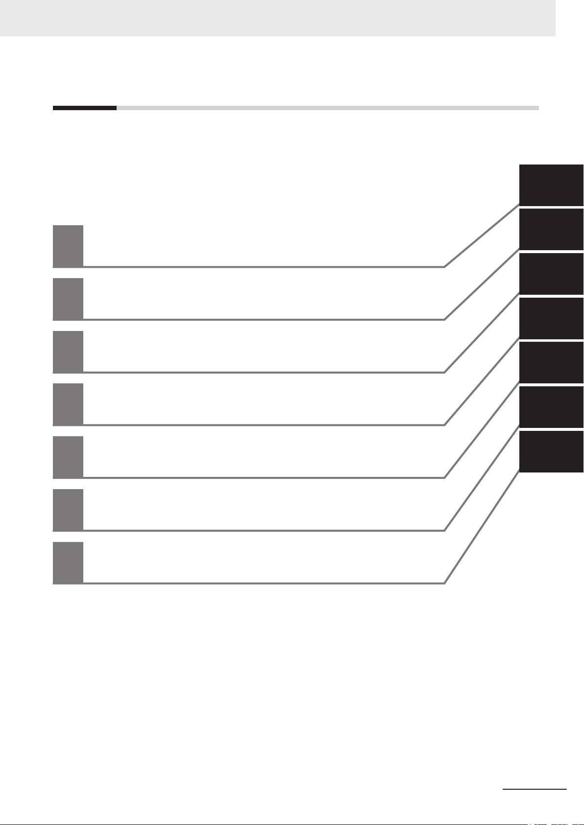
Sections in this Manual
Operating Procedures
Specifications
Installation
Software
Hardware
Overview
1
2
3
4
5
6
1
2
3
4
6
5
1
7
7
Maintenance
A
Sections in this Manual
NY-series Industrial Monitor User's Manual (W554)
27
Page 30

Sections in this Manual
28
NY-series Industrial Monitor User's Manual (W554)
Page 31

Overview
This section provides general information about the Industrial Monitor.
1-1
1-2 Hardware Features....................................................................................... 1 - 3
1-3 ID Information Label..................................................................................... 1 - 4
1-4 Product Configuration ................................................................................. 1 - 5
1-5 Industrial PC Platform Overview ................................................................ 1 - 6
1
Intended Use................................................................................................. 1 - 2
1-5-1 Industrial Monitor ......................................................................................... 1 - 6
1-5-2 Industrial Box PC ......................................................................................... 1 - 7
1-5-3 Industrial Panel PC ...................................................................................... 1 - 7
1
NY-series Industrial Monitor User's Manual (W554)
1 - 1
Page 32

1 Overview
1-1
Intended Use
The Industrial Monitor is intended to be used as a display and touch interface for the Industrial PC
Platform variants. The Industrial Monitor allows the user to interact through touch interactions on the
LCD display.
Users of the Industrial Monitor are able to set the brightness settings of both the LCD backlight and
the indicator LEDs. This allows the monitor to be configured for the required installation environment.
The Industrial Monitor additionally includes a USB hub to allow USB slave devices to be added at the
monitor location. Peripheral components such as a keyboard, mouse, or camera can be attached to
the monitor and used to control or be controlled by the operating system of the connected Industrial
PC.
1 - 2
NY-series Industrial Monitor User's Manual (W554)
Page 33

1 Overview
1-2 Hardware Features
1-2
Hardware Features
Depending on the product configuration the Industrial Monitor provides the following hardware fea-
tures.
• LCD touchscreen
The LCD touchscreen provides high functionality for your PC interface.
The high resolution and a high brightness provide clarity and high visibility.
• Multi-touch functionality
Up to 5 simultaneous touches are supported for complex functions.
• Backlit Logo
The standard product logo is OMRON. Check your sales representative for the possibilities to cus-
tomize the product logo. The product logo is provided with a controllable backlight to increase visibil-
ity.
• Status LED Indicator
The Monitor includes one multi-color LED indicator on the front of the product. The brightness of the
LED indicator is adjustable.
• Brightness control
Use the Monitor Utilities to control the Monitor's LCD brightness.
• DVI-D visual interface
The video interface for the Monitor is provided with a DVI connector for connection to the host PC.
• USB Type-B port for host PC
The USB Type-B port supports USB2.0 specifications. This port allows the host PC to communicate
with multiple internal USB devices within the Monitor as well as external devices connected to the
two USB Type-A ports. This communication includes the touchscreen functionality.
• NY Monitor Link interface
The combination of a video interface and a data connection using an NY Monitor Link cable. This
interface supports a touchscreen monitor connection over a distance up to 100 meter.
• USB Type-A ports for slave devices
Two USB Type-A ports are available for connection to external USB devices such as a keyboard,
mouse, camera, memory sticks, or other peripheral hardware.
1
NY-series Industrial Monitor User's Manual (W554)
1 - 3
Page 34

CUSTOM ID
D
OMRON Corporation Kyoto, 600-8530 JAPAN MADE IN THE NETHERLAND
S
INDUSTRIAL MONITOR
B
A
EF
C
NYM
1 Overview
1-3
ID Information Label
The ID information label contains relevant information of your Industrial Monitor.
Item Name Description
A Product name Industrial Monitor
B
C Power rating Power rating details
D Custom ID
E Standards and QR
F LOT number and
*1. Refer to 1-4 Product Configuration on page
*1
Model
(Optional)
code
serial number
Model and configuration details
A custom ID [NYC£££-££££££££]
Only for Industrial Monitor
The applicable standards and a QR code for OMRON internal use
Production details, consisting of:
• The lot number of the Industrial Monitor
DDMYY with Month number 1 to 9 for January to September, X for October, Y
for November, and Z for December.
£: For use by OMRON
s and Industrial Panel PCs with a custom logo *1.
in the format DDMYY£.
• Serial number (4 digits)
1 - 5 for model details.
Additional Information
Refer to 2-1-1 Front and T
label location.
1 - 4
op of the Industrial Monitor on page 2 - 2 for the ID information
NY-series Industrial Monitor User's Manual (W554)
Page 35

N Y M
1
2 3 4 5 6 7 8
1 Overview
1-4 Product Configuration
1-4
Product Configuration
This section provides an overview of the product configurations available for the Industrial Monitor.
The product configuration is visible in the model-type that is mentioned on the ID information label of
the Monitor.
The structure of the model-type is: NYM£££-£££££.
Each item in the model-type has a specific meaning.
Item Description Option
1 Series name NYM: NY- series Industrial Monitor
2 Display size
(diagonal)
3 Display ratio W: Wide
4 Touchscreen C: Projected Capacitive Touch type
5 Frame type 1: Aluminum frame, black
6 Design 0: Standard
7 Build-in options 0: None
8 Logo 0: OMRON
12: 12.1 inches
15: 15.4 inches
6: NY Monitor Link
2: Customization
1
NY-series Industrial Monitor User's Manual (W554)
1 - 5
Page 36

1 Overview
1-5
1-5-1
Industrial PC Platform Overview
The Industrial PC Platform is an integrated range of products designed for use in a variety of industrial
applications that will benefit from advanced PC technology. The range is scalable, robust and reliable,
and is suitable for use with both standard operating system software and proprietary programs for ma-
chine control and automation.
In line with OMRON’s established quality standards, each element in the Industrial PC Platform, rang-
ing from the standalone Industrial Box PC to the touchscreen Industrial Monitor, is engineered with
long-life components and built to the most advanced design standards.
The following sections introduce Industrial PC Platform products.
Industrial Monitor
The Industrial Monitor is of key importance at the interface between operator and system. The Indus-
trial Monitor is efficient, effective and highly visible with an attractive design.
Using smart algorithms, the touch controller determines the exact location of each touch for precise
control as well as detecting abnormal or illegal actions to protect misuse or false touches.
1 - 6
NY-series Industrial Monitor User's Manual (W554)
Page 37

1 Overview
1-5 Industrial PC Platform Over-
1-5-2
Industrial Box PC
The Industrial Box PC is designed to meet the specific needs of the industrial environment. Design
simplification and future-proof architecture minimize the risk of failure. In addition, new PC features
can be seamlessly incorporated, without the need for wholesale redesign.
view
1
1-5-2 Industrial Box PC
1-5-3
Industrial Panel PC
The Industrial Panel PC intelligently combines the functionality of the Industrial Box PC and Industrial
Monitor
and reliable operation in industrial environments.
. No cables are used between the two components, which ensures optimal signal distribution
NY-series Industrial Monitor User's Manual (W554)
1 - 7
Page 38

1 Overview
1 - 8
NY-series Industrial Monitor User's Manual (W554)
Page 39

2
2
Hardware
This section provides an overview of the hardware of the Industrial Monitor.
2-1
2-2 LED Indicators.............................................................................................. 2 - 4
2-3 Connectors ...................................................................................................2 - 6
2-4 Optional Hardware .....................................................................................2 - 10
Component Names and Functions............................................................. 2 - 2
2-1-1 Front and Top of the Industrial Monitor ......................................................... 2 - 2
2-1-2 Bottom of the Industrial Monitor.................................................................... 2 - 3
2-2-1 Logo LED...................................................................................................... 2 - 5
2-2-2 Status LED Indicator..................................................................................... 2 - 5
2-3-1 Power Connector .......................................................................................... 2 - 6
2-3-2 DVI-D Connector (Optional).......................................................................... 2 - 7
2-3-3 NY Monitor Link Connector (Optional).......................................................... 2 - 7
2-3-4 USB Type-A Connector ................................................................................ 2 - 8
2-3-5 USB Type-B Connector (Optional)................................................................ 2 - 9
2-4-1 DVI Cables.................................................................................................. 2 - 10
2-4-2 USB Type-A to USB Type-B Cables ............................................................2 - 11
2-4-3 NY Monitor Link Cables .............................................................................. 2 - 12
2-4-4 Power Supply.............................................................................................. 2 - 13
NY-series Industrial Monitor User's Manual (W554)
2 - 1
Page 40

B
D
A
C
2 Hardware
2-1
2-1-1
Component Names and Functions
This section shows views of the Industrial Monitor with information about all items.
Front and Top of the Industrial Monitor
This section shows the component names and functions for the front and top of the Industrial Monitor.
Item Name Description
A Logo Backlit logo with adjustable brightness
B Status LED Indicator Multi-colored LED to indicate power and connection status with adjustable
C ID Information Label Label containing Model ID., LOT No. and other product specific information.
D Touchscreen Multi-touch LCD display
brightness
Refer to 1-3 ID Information Label on page 1 - 4 for label details.
2 - 2
NY-series Industrial Monitor User's Manual (W554)
Page 41

A
B
C
D
F
E
A
G
C
F
E
2 Hardware
2-1 Component Names and Functions
2-1-2
Bottom of the Industrial Monitor
The monitor is available with a DVI-D connector and with an NYML connector.
For both versions all items on the bottom of the Industrial Monitor
Monitor with DVI-D connector Monitor with NYML connector
are identified here.
2
2-1-2 Bottom of the Industrial Monitor
Item Name Description
A Power Supply Connector 24 VDC power supply input connector
B
C USB Type-A
D USB Type-B
E Mounting Brackets 8 retractable mounting brackets to secure the Industrial Monitor on a
F Ground Terminal Terminal connection for grounding of the Industrial Monitor
G
*1. Refer to 1-4 Product Configuration on page
DVI-D Connector
Connectors
Connector
NYML Connector
*1
*1
DVI-D dual link connector for host video connection
2 USB connectors to connect external USB slave devices
USB connector for connection with the host PC
Only for Industrial Monitor
mounting surface
NY Monitor Link connector for video and USB communication with the
host PC
1 - 5 for model details.
s with a DVI-D connector.
NY-series Industrial Monitor User's Manual (W554)
2 - 3
Page 42

B
A
2 Hardware
2-2
LED Indicators
The Industrial Monitor has two LED indicators on the front of the product.
Item LED Description
A Logo LED LED to backlight the logo
B Status Indicator LED Indicates the operating condition of the Industrial Monitor.
2 - 4
NY-series Industrial Monitor User's Manual (W554)
Page 43

2 Hardware
2-2-1
2-2-2
Logo LED
The Logo LED brightness can be changed with the Industrial Monitor Utility.
Additional Information
The Logo LED brightness is adjustable.
Refer to Industrial Monitor Utility
The Industrial Monitor Utility information is available:
• For products NYM£ in the section Software in this manual.
• For products NYP£ in the section Support Software in this manual.
• For products NY5£ in the NY-series IPC Machine Controller Industrial Panel PC / Industrial
Box PC Setup User’s Manual (Cat. No. W568)
for brightness details.
Status LED Indicator
The Status LED indicator provides information about the operating condition of the Industrial Monitor.
Color Status Meaning
None Not lit The Status LED is not lit in following situations:
• The 24 VDC power is not supplied.
• Normal operation
Green Blinking The Status LED is blinking in following situations:
• The host PC is in standby mode.
• The host PC power is not supplied.
• The DVI cable or the NY Monitor Link cable is not connected.
Red Lit The Status LED is lit with maximum brightness in following situations:
• Power supply defective
• Monitor internal hardware error
2-2 LED Indicators
2
2-2-1 Logo LED
Additional Information
The Status LED indicator's brightness is adjustable.
Refer to Industrial Monitor Brightness Utility
on page 3 - 8 for brightness details.
NY-series Industrial Monitor User's Manual (W554)
2 - 5
Page 44

2 Hardware
2-3
2-3-1
Connectors
This section gives an overview of the available connectors for the Industrial Monitor.
Power Connector
The power connector on the Monitor is used to supply 24 VDC power to the Monitor.
The power connector is supplied with the Monitor.
Additional Information
• Refer to 4-2-1 Power Connector Specifications on page 4 - 4 for specifications.
•
Refer to 5-3-2 Wire the Power Connector on page 5 - 24 for wiring details.
• Refer to 5-4 Connect on page 5 - 26 for connection details.
2 - 6
NY-series Industrial Monitor User's Manual (W554)
Page 45

2 Hardware
2-3-2
DVI-D Connector (Optional)
Depending on the product configuration this DVI-D Connector is available.
The Digital V
isual Interface (DVI-D) connector connects a digital video source to the Industrial Monitor.
Additional Information
2-3 Connectors
2
2-3-2 DVI-D Connector (Optional)
2-3-3
• Refer to Product Configuration for configuration details.
•
Refer to 4-2-2 DVI-D Connector Specifications on page 4 - 5 for specifications.
• Refer to 5-4 Connect on page 5 - 26 for connection details.
NY Monitor Link Connector (Optional)
Depending on the product configuration this NY Monitor Link connector is available.
The NY Monitor Link interface connector connects an OMRON
Monitor.
Industrial PC to the OMRON Industrial
Industrial PC Industrial Monitor
NY-series Industrial Monitor User's Manual (W554)
2 - 7
Page 46
2 Hardware
Additional Information
2-3-4
• Refer to 1-4 Product Configuration on page
• Refer to 4-2-3 NY Monitor Link Connector Specifications on page 4 - 7 for specifications.
• Refer to 5-4 Connect on page 5 - 26 for connection details.
1 - 5 for configuration details.
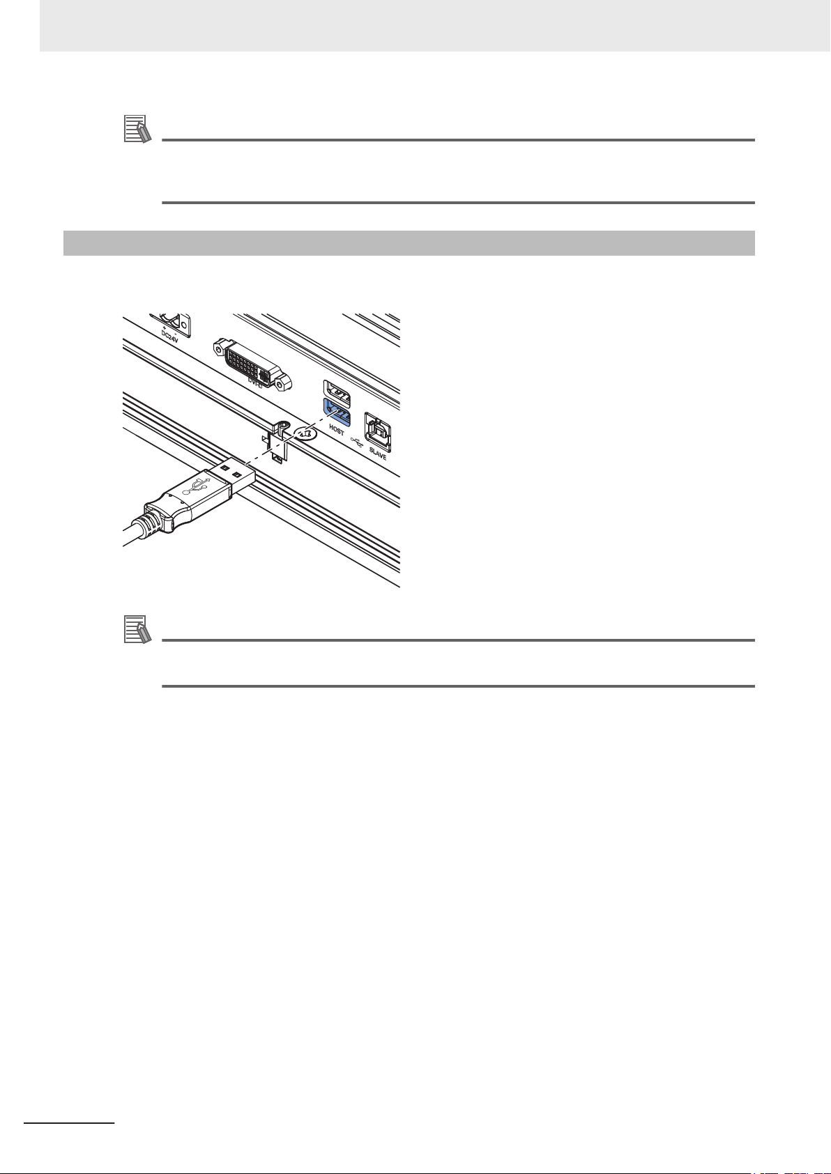
USB Type-A Connector
The Universal Serial Bus (USB) Type-A connectors provide a connection point on the Industrial Moni-
tor for USB slave devices.
Additional Information
• Refer to 4-2-4 USB T
• Refer to 5-4 Connect on page 5 - 26 for connection details.
ype-A Connector Specifications on page 4 - 9 for specifications.
2 - 8
NY-series Industrial Monitor User's Manual (W554)
Page 47

2 Hardware
2-3-5
USB Type-B Connector (Optional)
This USB Type-B connector is only available for product configurations without NY Monitor Link.
The Universal Serial Bus (USB) T
connector to the host PC. The host PC uses this interface to access the internal touchscreen functions
as well as external devices plugged into the USB Type-A connectors.
ype-B connector connects an Industrial Monitor that has a DVI-D
2-3 Connectors
2
2-3-5 USB Type-B Connector (Optional)
Additional Information
• Refer to Product Configuration for configuration details.
•
Refer to 4-2-5 USB Type-B Connector Specifications on page 4 - 10 for specifications.
• Refer to 5-4 Connect on page 5 - 26 for connection details.
NY-series Industrial Monitor User's Manual (W554)
2 - 9
Page 48

90 mm
2 Hardware
2-4
2-4-1
Optional Hardware
The following optional hardware is available for the Industrial Monitor.
DVI Cables
DVI cable details are provided below.
OMRON is not responsible for the operation or performance of any other brand of DVI cable.
Model Appearance Cable length Specifications
NY000AC00 2M
NY000AC00 5M
DVI Cable Clearance
The DVI cable requires a minimum clearance of 90 mm from the connector entry to prevent excessive
strain on the connector and cable assembly
2 m
5 m
• Supports DVI-D
• Minimum bend radius: 36 mm
.
2 - 10
NY-series Industrial Monitor User's Manual (W554)
Page 49

60 mm
2 Hardware
2-4-2
USB Type-A to USB Type-B Cables
USB Type-A to USB Type-B cable details are provided below.
OMRON is not responsible for the operation or performance of any other brand of USB T
Type-B cable.
Model Appearance Cable length Specifications
FH-VUAB 2M 2 m
FH-VUAB 5M 5 m
• USB 2.0
• Minimum bend radius: 25 mm
ype-A to USB
USB Type-A to USB Type-B Cable Clearance
The USB Type-A to USB Type-B cable requires a minimum clearance of 60 mm from the connector
entry to prevent excessive strain on the connector and cable assembly
.
2-4 Optional Hardware
2
2-4-2 USB Type-A to USB Type-B Cables
NY-series Industrial Monitor User's Manual (W554)
2 - 11
Page 50

2 Hardware
2-4-3
NY Monitor Link Cables
The following table lists the recommended cables and connectors for the NY Monitor Link cable.
Intra cabinet or
Application
Maximum length 25 m 100 m 100 m
Manufacturer Lapp Lapp Lapp
Cable type 2170196 2170614 2170466
Category type Cat 6A Cat 7 Cat 6A
Cable sheath Halogen free Halogen free Halogen free
Conductor pairs/size/type 4 x 2 x AWG23/1 4 x 2 x AWG23/1 4 x 2 x AWG22/1
Overall shielding Aluminum foil Copper braid Copper braid
Pair shielding Aluminum foil Aluminum foil Aluminum foil
Maximum outer diameter 7.6 mm 7.7 mm 9.0 mm
Maximum bending radius of cable in a
fixed position
Maximum temperature for a cable in a
fixed position
RJ45 connectors Manufacturer Stewart Connector Stewart Connector Lapp
Partnumber SS39200-027 or
Connector length 30 mm 30 mm 50 mm
light industrial en-
vironment
31 mm 31 mm 90 mm
60°C 60°C 80°C
SS39200-030
Inter cabinet
SS39200-027 or
SS39200-030
Inter cabinet and
harsh industrial
environment
21700600 (T568A)
or 21700601
(T568B)
Additional Information
When making cables, connect the shield to the connectors at both ends.
NY Monitor Link Cable Clearance
The NY Monitor Link cable requires a minimum clearance from the connector entry to prevent exces-
sive strain on the connector and cable assembly
The minimum clearance consists of the sum of:
• Connector length
• Maximum bending radius of cable in a fixed position
.
2 - 12
NY-series Industrial Monitor User's Manual (W554)
Page 51

2 Hardware
2-4-4
Power Supply
Details for the recommended power supply are provided below.
OMRON is not responsible for the operation or performance of any other power supply
Model Appearance Specifications
S8VK-G£££24
Additional Information
• Refer to 4-1-2 General Electrical Specifications on page 4 - 3 for power consumption details.
Refer to
•
Note that the power consumption details of the
of your power supply.
the OMRON website for specifications and manuals of the S8VK-G.
Monitor determine the minimum power rating
Output voltage: 24 VDC
.
2-4 Optional Hardware
2
2-4-4 Power Supply
NY-series Industrial Monitor User's Manual (W554)
2 - 13
Page 52

2 Hardware
2 - 14
NY-series Industrial Monitor User's Manual (W554)
Page 53

Software
3
3
This section provides software information for the Industrial Monitor.
3-1
Operating Systems ...................................................................................... 3 - 2
3-1-1 Touch Functionality ....................................................................................... 3 - 2
3-1-2 Determine Your Version of the Windows Operating Systems....................... 3 - 3
3-2 Support Software .........................................................................................3 - 4
3-2-1 Overview IPC Support Software for Windows .............................................. 3 - 4
3-2-2 Industrial Monitor Utility ............................................................................... 3 - 5
3-2-3 Industrial Monitor Brightness Utility ............................................................. 3 - 8
3-2-4 Industrial PC Tray Utility ............................................................................ 3 - 10
3-3 Software for Developers............................................................................ 3 - 13
3-3-1 Overview IPC Developer Software for Windows ........................................ 3 - 13
3-3-2 Industrial Monitor API ................................................................................ 3 - 14
NY-series Industrial Monitor User's Manual (W554)
3 - 1
Page 54

3 Software
3-1
3-1-1
Operating Systems
The Monitor does not have an operating system.
To use the Monitor a host PC with an operating system is required. This section provides information
about the parts of the operating system that influence the performance, behavior or software of your
Monitor.
Touch Functionality
This section provides an overview of the touch functionality of your Industrial Monitor.
Requirements
To use touch functionality
• The Operating System has to support tablet PC features
• Touch functionality drivers have to be installed
Calibration
The touch functionality is calibrated for the default screen resolution.
Calibrate the display when setting a different resolution results in displaying your content on only a
part of the display.
Additional Information
• Refer to 4-3 Display Specifications on page 4 - 11 for the default resolution.
• Refer to Calibrate Touchscreen on page 7 - 10 for calibration details.
3 - 2
NY-series Industrial Monitor User's Manual (W554)
Page 55

3 Software
3-1-2
Determine Your Version of the Windows Operating Systems
This section provides methods to find version details of your Windows Operating System.
Windows 7
To determine your version of the Windows Operating System:
1 Select the Start Button.
2 Enter System Information in the search box.
3 Select System Information in the pop-up that appears.
An overview of your System Information will appear
details.
Windows 10
To determine your version of the Windows Operating System:
, including the Windows Operating System
3-1 Operating Systems
3
3-1-2 Determine Your Version of the Windows Operating Systems
1 Select the Search Button.
2 Enter System Information in the search box.
3 Select System Information
An overview of your System Information will appear, including the Windows Operating System
details.
in the pop-up that appears.
NY-series Industrial Monitor User's Manual (W554)
3 - 3
Page 56

3 Software
3-2
3-2-1
Support Software
This section provides an overview of the support software available for your Industrial Monitor.
Overview IPC Support Software for Windows
This section gives an overview of the software utilities available for all Industrial PC Platform products
with a Windows operating system.
Product Software utility
Industrial Monitor Industrial Monitor Utility
Industrial Monitor Brightness Utility
Industrial PC T
Industrial Box PC Industrial PC Support Utility
Industrial PC T
Industrial Panel PC Industrial Monitor Utility
Industrial Monitor Brightness Utility
Industrial PC Support Utility
Industrial PC T
Select and download the utilities required from the OMRON download website.
ray Utility
ray Utility
ray Utility
Additional Information
• An internet connection is required to install support software.
•
Refer to NY-series Industrial Panel PC User’s Manual (Cat. No. W555) for support software
details.
3 - 4
NY-series Industrial Monitor User's Manual (W554)
Page 57

A
B
C
D
E
F
G
I
J
K
H
3 Software
3-2-2
Industrial Monitor Utility
This section provides an overview of the Industrial Monitor Utility.
Industrial Monitor Utility Overview
The Industrial Monitor Utility provides a user interface to control settings and display details of con-
nected Industrial Monitor
s.
3-2 Support Software
3
3-2-2 Industrial Monitor Utility
Item Description Details
A Connected Monitors
B Product Information Provides the following details of the selected Industrial Monitor.
Shows a list of the connected Industrial Monitors.*1 Select one
Monitor in the list to display the Monitor Details. When selected the LED Indicators of the selected monitor will flash during 3 seconds.
Industrial
• Serial Number
• Screen Size
• Hardware V
ersion
• Software Version
• Model Name
• Factory Identifier
• Unit Lot Number
• Logo Type
• Video Status
C Monitor Settings Provides several setting adjustments to control the operation of the selected
Industrial Monitor
D Backlight Brightness Ad-
justment
E Logo Brightness Adjust-
ment
F Status Brightness Adjust-
ment
*2
G Advanced Settings Provides advanced setting adjustments to control the operation of the se-
H Restore Factory Defaults Restores the factory default settings of the selected Industrial Monitor.
Use the slider to control the brightness of the selected Industrial Monitor.
Use the slider to control the brightness of the Logo LED.
Refer to 2-2-1 Logo LED on page
Use the slider to control the brightness of the Status LED Indicator on the
.
monitor
Refer to 2-2-2 Status LED Indicator on page 2 - 5 for details about the operation of the Status LED Indicator.
Industrial Monitor.
lected
.
2 - 5 for details about the Logo LED.
NY-series Industrial Monitor User's Manual (W554)
3 - 5
Page 58

3 Software
*1. The Industrial Monitor Utility scans the connected USB devices and shows a list of connected monitors. If an
*2. With a very low backlight brightness setting (15%-0%) the displayed information might not be visible in an envi-
Item Description Details
I OK button Applies the changes and closes the window
J Cancel button Exits the utility
K Apply button Applies the changes
Industrial Monitor
ronment with high ambient light conditions. This prevents brightness adjustments with the Industrial Monitor Utility.
Additional Information
To adjust the backlight brightness when the brightness setting is set too low:
• Bring the Monitor
• Lighten the display with a bright flashlight
is not connected with the USB cable, it will not be found.
in a low ambient light environment
Compatibility
This monitor utility can be used on any PC that is connected to an OMRON Industrial Monitor.
This monitor utility can be used with:
Windows Embedded Standard 7
•
• Windows 10
Additional Information
This monitor utility does not support 3rd party monitors.
Installation
The Industrial Monitor Utility is pre-installed on the Industrial Box PC and the Industrial Panel PC.
Download the
stallation on another Industrial PC.
The Industrial Monitor Utility is installed onto Windows, and can be accessed via the Windows start
menu and the Industrial PC Tray Utility. Installing the Industrial Monitor Utility will also install the Indus-
trial PC Tray Utility.
Industrial Monitor Utility from the OMRON download website for re-installation or for in-
3 - 6
Additional Information
Refer to 3-2-4 Industrial PC T
ray Utility on page 3 - 10 for Industrial PC Tray Utility details.
Startup
The Industrial Monitor Utility can be started from:
Windows Start Menu.
•
Select Omron and then Industrial Monitor Utility.
• Industrial PC Tray Utility
NY-series Industrial Monitor User's Manual (W554)
Page 59

3 Software
Configuration
The Industrial Monitor Utility can be configured with following options:
Configuration item Description
Language Follows the Windows language configuration when that language is supported for the
Industrial Monitor Utility
guage configured in Windows is not supported.
Monitor identification If enabled, the Status LED indicator on the selected Industrial Monitor will flash for 3
seconds.
o enable:
T
(1) Open the Windows registry key HKEY_LOCAL_MACHINE\SOFTWARE
\Wow6432Node\Omron\IPC\MonitorConfiguration
(2) Set the registry value Indicate to value True.
. The default language English (EN-US) will be used if the lan-
3-2 Support Software
3
Messages
The Industrial Monitor Utility can use the Industrial PC Tray Utility to display following messages:
Message type Message Description
Info Connected A new monitor connected
• USB cable connected
• Monitor powered ON
Warning Not Connected Monitor disconnected
• USB cable disconnected
• Monitor powered OFF
Warning Video Discon-
nected
Warning No Signal DVI cable connected but no signal detected
DVI cable disconnected or NY Monitor Link cable disconnected
Logging
There is logging in the Windows event log of the following utilities:
• Industrial Monitor Utility
In the Windows Event Viewer filter for event source IndMonService.
• Industrial Monitor Brightness Utility
In the Windows Event Viewer filter for event source IndMonService.
• Industrial PC Support Utility
In the Windows Event Viewer filter for event source IPCServiceHost or OMRON Industrial PC
Support Utility.
3-2-2 Industrial Monitor Utility
Additional Information
Refer to 7-2-2 Windows Event Viewer on page 7 - 5 for the logged messages.
NY-series Industrial Monitor User's Manual (W554)
3 - 7
Page 60

A
B
3 Software
3-2-3
Industrial Monitor Brightness Utility
This section provides an overview of the Industrial Monitor Brightness Utility.
Industrial Monitor Brightness Utility
The Industrial Monitor Brightness Utility is a software utility that allows you to control the brightness of
the screen backlight of all connected
Industrial Monitors.
Item Description Details
A Backlight brightness slider Use the slider to control the display brightness of all connected Industrial
Monitors.
B Industrial Monitor Utility Button to start the Industrial Monitor Utility.
With a very low backlight brightness setting (15%-0%) the displayed information might not be visible in
an environment with high ambient light conditions. This prevents brightness adjustments with the In-
dustrial Monitor Brightness Utility.
Additional Information
To adjust the backlight brightness when the brightness setting is set too low:
• Bring the Monitor in a low ambient light environment
• Lighten the display with a bright flashlight
Compatibility
This monitor utility can be used on any PC that is connected to an OMRON Industrial Monitor.
This monitor utility can be used with:
• Windows Embedded Standard 7
• Windows 10
3 - 8
Additional Information
This monitor utility does not support 3rd party monitors.
NY-series Industrial Monitor User's Manual (W554)
Page 61

3 Software
Installation
The Industrial Monitor Brightness Utility is pre-installed on the Industrial Box PC and the Industrial
Panel PC
Installation of the Industrial Monitor Brightness Utility is part of the installation of the Industrial Monitor
Utility.
Download the Industrial Monitor Utility from the OMRON download website for re-installation or for in-
stallation on another PC with Windows 7.
The Industrial Monitor Brightness Utility is installed onto Windows, and can be accessed via the Win-
dows start menu and the Industrial PC Tray Utility. Installing the Industrial Monitor Utility will also in-
stall the Industrial PC Tray Utility.
.
3-2 Support Software
Additional Information
Refer to 3-2-4 Industrial PC T
ray Utility on page 3 - 10 for Industrial PC Tray Utility details.
Startup
Start the Industrial Monitor Brightness Utility from the Industrial PC Tray Utility or from the Windows
Start Menu (select Omron and then Industrial Monitor Brightness Utility
Additional Information
Refer to 3-2-4 Industrial PC T
ray Utility on page 3 - 10 for Industrial PC Tray Utility details.
).
Configuration
Configuration is not required. This Industrial Monitor Brightness Utility will detect and support all con-
nected NY
-series Industrial Monitors.
Logging
3
3-2-3 Industrial Monitor Brightness Utility
There is logging in the Windows event log of the following utilities:
•
Industrial Monitor Utility
In the Windows Event Viewer filter for event source IndMonService.
• Industrial Monitor Brightness Utility
In the Windows Event Viewer filter for event source IndMonService.
• Industrial PC Support Utility
In the Windows Event Viewer filter for event source IPCServiceHost or OMRON Industrial PC
Support Utility.
Additional Information
Refer to 7-2-2 W
NY-series Industrial Monitor User's Manual (W554)
indows Event Viewer on page 7 - 5 for the logged messages.
3 - 9
Page 62

A
B
A B
B
C
E
F
D
A
3 Software
3-2-4
Industrial PC Tray Utility
This section provides an overview of the Industrial PC Tray Utility.
Industrial PC Tray Utility Overview
The Industrial PC Tray Utility is a software utility that provides information about the current state of
the Industrial PC, its related devices, and associated software.
When running, the
area
Windows 10
of Windows.
Industrial PC Tray Utility is always present as a status icon
in the system tray
Features
The Industrial PC Tray Utility provides the following features:
•
Display the overall state of all installed OMRON utilities in the icon in the system tray area.
• Display a menu that can start all installed utilities and show the state of each installed utility.
• Display notification messages in popup windows that inform the user about the state of applications
or hardware. The Industrial PC Tray Utility displays the messages provided by installed OMRON
utilities. Refer to the OMRON utilities information for the messages that can be displayed.
Menu
Select the Industrial PC Tray Utility icon F to display the menu.
3 - 10
• The application displays the available utilities.
•
Select an entry to launch the associated utility, if applicable.
NY-series Industrial Monitor User's Manual (W554)
Page 63

A
B
C
E
3 Software
• The icons of menu items in the Industrial PC Tray Utility menu will have a warning or error symbol
when applicable.
•
The Industrial PC Support Utility
•
The Industrial Monitor Utility
The Industrial Monitor Brightness Utility
•
The application area can be configured to show and launch both OMRON and third party utilities.
•
• The About entry
Refer to About the Industrial PC T
• The Exit entry
shows details of the Industrial PC Tray Utility.
closes the utility.
is available in the menu when installed.
is available in the menu when installed.
is available in the menu when installed.
ray Utility on page 3 - 11 for details.
About the Industrial PC Tray Utility
The About window shows the version of the Industrial PC Tray Utility and copyright information.
3-2 Support Software
3
3-2-4 Industrial PC Tray Utility
Status Indicators on Icons
The following table provides the indicator details of the Industrial PC Tray Utility.
Overlay type Icon Description
None No OMRON utility has issued warning or error notifications.
Warning sign At least one OMRON utility has issued a warning notification.
Error sign At least one OMRON utility has issued an error notification.
NY-series Industrial Monitor User's Manual (W554)
3 - 11
Page 64

3 Software
This software utility can be used on PCs with Windows 7 and Windows 10.
The Industrial PC Tray Utility is pre-installed on an Industrial Box PC and an Industrial Panel PC.
The Industrial PC T
trial Monitor Utility. Install the Industrial PC Support Utility or Industrial Monitor Utility to install the In-
dustrial PC Tray Utility.
By default the Industrial PC Tray Utility is configured to start automatically at Windows startup.
Compatibility
Installation
ray Utility is included in the installers of the Industrial PC Support Utility and Indus-
Startup
T
o manually start the Industrial PC Tray Utility:
1 Locate the Industrial PC Tray Utility using the Windows Start menu or the Windows search
box.
2 Use the option Run as administrator to activate the Industrial PC T
Additional Information
The procedure to use Run as administrator is:
For Windows 10 using the Start menu:
•
Rightclick the Industrial PC Tray Utility, select More and then Run as administrator.
• For Windows 10 using Search:
Rightclick the Industrial PC Tray Utility in the search results and select Run as
administrator.
• For Windows 7 using the Start menu or Search:
Rightclick the Industrial PC Tray Utility and select Run as administrator.
The Industrial PC Tray Utility started.
ray Utility.
3 - 12
NY-series Industrial Monitor User's Manual (W554)
Page 65

3 Software
3-3
3-3-1
Software for Developers
This section provides information on the software that is available for developers.
Overview IPC Developer Software for Windows
This section gives an overview of the software available for developers for all Industrial PC Platform
products with a Windows operating system.
Product Developer software
Industrial Monitor Industrial Monitor SDK
Industrial Monitor API
Industrial Box PC Industrial PC System SDK
Industrial PC System API
Industrial Panel PC Industrial Monitor SDK
Industrial Monitor API
Industrial PC System SDK
Industrial PC System API
Select and download the software required from the OMRON download website.
3-3 Software for Developers
3
3-3-1 Overview IPC Developer Software for Windows
NY-series Industrial Monitor User's Manual (W554)
3 - 13
Page 66

3 Software
3-3-2
Industrial Monitor API
This section describes some of the Industrial Monitor API functions.
The Industrial Monitor API
features and retrieve information from connected Industrial Monitors.
The main function of the Industrial Monitor API is to enable the brightness of the backlight and the
LEDs of the monitor to be increased or decreased according to the working environment.
The API makes use of the included OMRON Industrial Monitor Service to manage the hardware.
allows programmers to create applications that can control the hardware
Features
For all connected Industrial Monitors, the Industrial Monitor API can:
•
Retrieve product information from the Industrial Monitor or Industrial Panel PC display
• Retrieve product status information
• Set the brightness of the Status LED indicator
• Set the brightness of the backlight
• Set the brightness of the Logo LED
• Set the touch points of the monitor
• Store settings
• Restore to factory defaults
The API makes use of the included Industrial Monitor Service to manage all Industrial Monitors con-
nected via USB.
Installation
The Industrial Monitor API is part of the SDK download.
The Industrial Monitor API
Install the Industrial Monitor SDK to use the Industrial Monitor API on development PCs.
Use the Merge Module to include the Industrial Monitor API in the installer for custom applications.
To use the Industrial Monitor API the API needs to be referenced in your development project.
is pre-installed on the Industrial Panel PC and Industrial Box PC.
3 - 14
NY-series Industrial Monitor User's Manual (W554)
Page 67

Specifications
This section provides specifications of the Industrial Monitor.
4
4
4-1
General Specifications ............................................................................... 4 - 2
4-1-1 Dimensions and Weight................................................................................ 4 - 2
4-1-2 General Electrical Specifications .................................................................. 4 - 3
4-2 Connector Specifications ........................................................................... 4 - 4
4-2-1 Power Connector Specifications................................................................... 4 - 4
4-2-2 DVI-D Connector Specifications ................................................................... 4 - 5
4-2-3 NY Monitor Link Connector Specifications ................................................... 4 - 7
4-2-4 USB Type-A Connector Specifications ......................................................... 4 - 9
4-2-5 USB Type-B Connector Specifications ....................................................... 4 - 10
4-3 Display Specifications ............................................................................... 4 - 11
4-4 Environmental Specifications................................................................... 4 - 12
4-4-1 Operation Environment Specifications........................................................ 4 - 12
4-4-2 Temperature and Humidity Specifications .................................................. 4 - 13
4-4-3 Recycling Specifications ............................................................................. 4 - 14
NY-series Industrial Monitor User's Manual (W554)
4 - 1
Page 68

Z
Y
X
R
4 Specifications
4-1
4-1-1
General Specifications
This section provides general specifications of the Industrial Monitor.
Dimensions and Weight
The following table provides specification details on dimensions and weights.
Item
Dimensions Width X = 332 mm
Height Y = 234 mm
Depth Z = 66 mm
Monitor thickness on top of panel Rim thickness R = 8.0 mm
Weight 3.3 kg 4.3 kg
*1. Refer to 1-4 Product Configuration on page
12.1 Inch
1 - 5 for details.
*1
Specifications
Width X = 401 mm
Height Y = 277 mm
Depth Z = 66 mm
15.4 Inch
*1
4 - 2
NY-series Industrial Monitor User's Manual (W554)
Page 69

4 Specifications
4-1-2
General Electrical Specifications
The following table provides the general electrical specifications.
Item
Rated power supply voltage 24 VDC
Allowable power supply voltage range 19.2 to 28.8 VDC
Power supply standard SELV
Grounding method Ground to less than 100 Ω
Power consumption With DVI-D interface 25 W max.
With NY Monitor Link interface
Inrush current At 24 VDC: 5 A / 10ms max.
Overvoltage category JIS B3502 and IEC 61131-2: Category II
EMC immunity level IEC 61132-2: Zone B
*1. Refer to 1-4 Product Configuration on page
1 - 5 for details.
12.1 Inch
30 W max. 31 W max.
Specifications
*1
15.4 Inch
*1
4-1 General Specifications
4
4-1-2 General Electrical Specifications
NY-series Industrial Monitor User's Manual (W554)
4 - 3
Page 70

1
2
4 Specifications
4-2
4-2-1
Connector Specifications
This section provides the Connector Specifications of the Industrial Monitor.
Power Connector Specifications
The power connector is used to supply 24 VDC power to the Industrial Monitor.
The connector can only be inserted the correct way.
The connector is a Phoenix Contact type FKCT 2,5/ 2-STF-5,08 BK (1711707).
The pin layout represents the power connector on the Industrial Monitor.
Pin Description
1 24 VDC
2 0 VDC
Item Specifications
Conductor isolation rating 90°C
Termination rating 90°C
Additional Information
• Refer to 5-3-2 W
• Refer to 5-3-1 Ground on page 5 - 17 for grounding details.
• Refer to 5-4 Connect on page 5 - 26 for connection details.
ire the Power Connector on page 5 - 24 for wiring details.
4 - 4
NY-series Industrial Monitor User's Manual (W554)
Page 71

4 Specifications
4-2-2
DVI-D Connector Specifications
The DVI-D connector is a single-link connection type for connection with the host PC. The connector
follows the DVI-D dual-link assembly design.
The connector includes support for the Display Data Channel (DDC) and can transmit the
Monitor's supported display modes to the host PC through this channel.
The Industrial Monitor can detect if the DVI cable is not connected or that the host PC is not powered
or the DVI port on the host PC is disabled.
Industrial
4-2 Connector Specifications
4
4-2-2 DVI-D Connector Specifications
Item Specifications
Video interface Digital only
Resolution 1,280 x 800 pixels at 60 Hz
Maximum DVI cable length 5 m
Additional Information
• Refer to 5-3-1 Ground
• Refer to 5-4 Connect on page 5 - 26 for connect details.
on page 5 - 17 for grounding details.
NY-series Industrial Monitor User's Manual (W554)
4 - 5
Page 72

1 8
9 16
17 24
C
5
4 Specifications
DVI-D Connector Pin Details
Pin details of the DVI-D connector.
The pin layout represents the DVI connector on the Industrial Monitor.
Pin numbers increase from left to right for every row.
Pin Signal Name Function
1 TMDS data 2− Digital red− (link 1)
2 TMDS data 2+ Digital red+ (link 1)
3 0 VDC TMDS data 2/4 shield
4 Not connected ---
5 Not connected ---
6 DDC clock DDC clock
7 DDC data DDC data
8 Not connected ---
9 TMDS data 1− Digital green− (link 1)
10 TMDS data 1+ Digital green+ (link 1)
11 0 VDC TMDS data 1/3 shield
12 Not connected ---
13 Not connected ---
14 +5 V Power for monitor DDC interface
15 0 V Return for pin 14
16 HPD Hot plug detect
17 TMDS data 0− Digital blue− (link 1) and digital sync
18 TMDS data 0+ Digital blue+ (link 1) and digital sync
19 0 VDC TMDS data 0/5 shield
20 Not connected ---
21 Not connected ---
22 0 VDC TMDS clock shield
23 TMDS clock+ Digital clock+
24 TMDS clock− Digital clock−
C5 Not connected ---
4 - 6
NY-series Industrial Monitor User's Manual (W554)
Page 73

4 Specifications
4-2-3
NY Monitor Link Connector Specifications
The NY Monitor Link connector connects an OMRON Industrial Monitor with an OMRON Industrial PC
that has an NY monitor link connector
The NY Monitor Link communication is a combination of video and USB information.
Item Specifications
Connector type RJ45
Transmission media Twisted pair cable of category 6A or higher (double-shielded
Maximum cable length between Industrial PC
and Industrial Monitor
Topology
Video resolution 1.280 x 800 pixels at 60 Hz
Data throughput rate 280 Mbps max.
*1. Use a direct connection between the OMRON Industrial PC and the OMRON Industrial Monitor.
Do not use:
• Ethernet switches
• Ethernet hubs
• Daisy chain connections
The NY Monitor Link connector locks automatically to prevent unintentional disconnection.
.
straight cable with copper braiding and aluminum foil)
100 m
Line (direct) connection only
*1
4-2 Connector Specifications
4
4-2-3 NY Monitor Link Connector Specifications
Industrial PC Industrial Monitor
NY-series Industrial Monitor User's Manual (W554)
4 - 7
Page 74

NYML
B
A
4 Specifications
NY Monitor Link Connector LED Indicators
The connector has LED indicators Connected A and Video B.
Item
A Con-
B Video Green Not lit No video signal
Indica-
tor
nected
Color Status Description
Yellow
Not lit Not connected
Lit Connected
USB communication active
Blinking Video signal present
Lit Encrypted video signal present
V
ideo output is not supported for encrypted video.
4 - 8
NY-series Industrial Monitor User's Manual (W554)
Page 75

1
2
HOST
4 Specifications
4-2-4
USB Type-A Connector Specifications
The USB Type-A connectors are used for connection with slave USB devices like USB Memory De-
vice, keyboard or mouse. This functionality is only available when the USB T
nected to an Industrial PC.
Details of the USB Type-A interface connectors are provided below.
ype-B connector is con-
4-2 Connector Specifications
4
4-2-4 USB Type-A Connector Specifications
Interface Connector Details
1
2
Additional Information
• Refer to 5-3-1 Ground
• Refer to 5-4 Connect on page 5 - 26 for connection details.
• USB 2.0
• 500 mA maximum current
• 5 m maximum cable length
on page 5 - 17 for grounding details.
NY-series Industrial Monitor User's Manual (W554)
4 - 9
Page 76

4 Specifications
4-2-5
USB Type-B Connector Specifications
The USB Type-B connector is used for connection with the host PC to allow communication to internal
and external USB devices. The host PC uses this interface to access the internal touchscreen func-
tions as well as other external devices plugged into the USB T
Type-B interface connector are provided below.
ype-A connectors. Details on the USB
Item Details
USB Type-B connector
Additional Information
• Refer to 5-3-1 Ground
• Refer to 5-4 Connect on page 5 - 26 for connection details.
• USB 2.0
• 5 m maximum cable length
on page 5 - 17 for grounding details.
4 - 10
NY-series Industrial Monitor User's Manual (W554)
Page 77

4 Specifications
4-3
Display Specifications
This section provides the display specifications of the Industrial Monitor.
WARNING
Do not use the input functions of the touchscreen in applications that involve human life, in applications that may result in serious injury
emergency stop switches.
Precautions for Correct Use
The touchscreen supports 5 simultaneous touches. When the number of touches is exceeded,
not all touch points will be detected.
Item
*2
Display panel
Touch Technology Projected capacitive
Backlight Life
*1. Refer to 1-4 Product Configuration on page
*2. There may be some defective pixels in the display. This is not a fault as long as the number of defective light
and dark pixels fall within the following standard range: light and dark pixels 10 or less. There must not be 3
adjacent light/dark pixels.
*3. Refer to 4-1-2 General Electrical Specifications on page 4 - 3 for EMC immunity level specifications.
*4. If water is detected the touch functionality will not be available.
*5. If a palm is detected that specific area is neglected.
*6. The touchscreen can be operated when wearing gloves. Confirm you can operate the touchscreen with
gloves before actual operation.
*7. This is the estimated time before brightness is reduced by half at room temperature.
The life expectancy is drastically shortened if used at high temperatures.
*8. If the brightness is set to very dark, it causes flickering or the screen will be too dark to use.
Display device TFT LCD
Screen size 12.1 inches 15.4 inches
Surface treatment Anti glare treatment
Surface hardness Mohs scale 5-6
Resolution 1,280 × 800 pixels at 60 Hz (horizontal × vertical)
Colors 16,770,000 colors
Effective display
area
View angles Left: 60°, Right: 60°, Top: 60°, Bottom: 60°
Life 50,000,000 operations minimum
EMC Correct touchscreen operation is possible within allowable EMC immuni-
Touch resolution Touch accuracy 1.5% (4-5mm)
Multitouch Up to 5 simultaneous touches
Features
Brightness adjust-
*8
ment
261 × 163 mm (horizontal × vertical)
ty conditions
Water detection*4, hand palm rejection*5, gloves
50,000 hours minimum.
200 levels
12.1 Inch
*3
1 - 5 for details.
*1
*7
, or for
Model Specifications
331 × 207 mm (horizontal × vertical)
15.4 Inch
*6
*1
4-3 Display Specifications
4
NY-series Industrial Monitor User's Manual (W554)
4 - 11
Page 78

4 Specifications
4-4
4-4-1
Environmental Specifications
This section provides environmental specifications of the Industrial Monitor.
Operation Environment Specifications
The following table provides general environmental specifications for the Industrial Monitor.
Item
Ambient operating temperature
Ambient storage temperature
Ambient operating humidity
Ambient storage humidity
Operating atmosphere No corrosive gases
Altitude 2,000 m max.
Noise resistance (during operation) Conforms to IEC 61000-4-4, 2kV (power lines)
Vibration resistance (during operation)
Shock resistance (during operation) Conforms to IEC 60068-2-27.
Degree of protection
Pollution degree 2 or less: Conforms to JIS B3502 and IEC 61131-2
*1. Refer to 1-4 Product Configuration on page
*2. Refer to 4-4-2 Temperature and Humidity Specifications on page 4 - 13 for ambient operating temperature
and humidity details.
*3. The Industrial Monitor may not operate properly in locations subjected to oil splashes for extended periods
of time.
0 to 55°C
-20 to 70°C
10% to 90% with no condensation
10% to 90% with no condensation
Conforms to IEC 60068-2-6.
5 to 8.4 Hz with 3.5 mm single amplitude and 8.4 to 150 Hz with 9.8 m/s²
for 10 times each in X, Y and Z directions
147 m/s², 3 times each in X, Y and Z directions
Front of product: IP65
12.1 Inch
*2
*2
1 - 5 for details.
*1
*3
Specifications
*2
*2
15.4 Inch
*1
4 - 12
NY-series Industrial Monitor User's Manual (W554)
Page 79

Humidity [%]
Operating
temperaturehumidity range
Temperature [°C]
0
1
0
20
30
40
50
60
70
80
90
100
-30 -20 -10 0 10 20 30 40 50 60 70 80
0
10
20
30
40
50
60
70
80
90
100
Operating
t
emperature-humidity
range
Humidity [%]
Storage
temperaturehumidity range
Temperature [°C]
0
1
0
20
30
40
50
60
70
80
90
100
-30 -20 -10 0 10 20 30 40 50 60 70 80
0
10
20
30
40
50
60
70
80
90
100
Storage
t
emperature-humidity
range
4 Specifications
4-4-2
Temperature and Humidity Specifications
The allowed ambient temperature and humidity conditions during operation and storage of the Indus-
trial Monitor are specified in the following graphs.
Operate the Industrial Monitor within the ambient temperature and humidity ranges as shown in fol-
•
lowing graph.
The ambient operating temperature specifications do not depend on the mounting angle, orientation
or display size.
4-4 Environmental Specifications
4
4-4-2 Temperature and Humidity Specifications
Store the Industrial Monitor within the ambient temperature and humidity ranges as shown in follow-
•
ing graph.
NY-series Industrial Monitor User's Manual (W554)
4 - 13
Page 80

90° to 135
°
4
5° to 90
°
0° to 45
°
4 Specifications
Monitor Temperature Specifications
Ambient operating temperature specifications for a Monitor
Configuration
Product Orientation Mounting Angle
Landscape and Portrait 0° to 45° 0 to 55°C 0 to 50°C
Landscape 45° to 90° 0 to 55°C
90° to 135° 0 to 55°C
Portrait 45° to 90° 0 to 55°C
90° to 135° 0 to 55°C
*1. Refer to 1-4 Product Configuration on page
1 - 5 for model details.
With a DVI-D interface
With an NY Monitor Link
Additional Information
*1
interface
4-4-3
Refer to 4-4-2 Temperature and Humidity Specifications on page 4 - 13 for graph details.
Recycling Specifications
The following table provides recycling information for the Industrial Monitor.
Part Recycle Specifications
Boards and other electrical components Electrical waste
4 - 14
NY-series Industrial Monitor User's Manual (W554)
Page 81

Installation
This section provides all installation details for the Industrial Monitor.
5-1
Unpack ..........................................................................................................5 - 2
5-1-1 Unpack Procedure ........................................................................................ 5 - 2
5-1-2 Items Supplied .............................................................................................. 5 - 3
5-2 Mount............................................................................................................. 5 - 4
5-2-1 Installation Method in Control Panels ........................................................... 5 - 4
5-2-2 Product Orientation....................................................................................... 5 - 5
5-2-3 Temperature.................................................................................................. 5 - 6
5-2-4 Humidity........................................................................................................ 5 - 8
5-2-5 Vibration and Shock...................................................................................... 5 - 8
5-2-6 Atmosphere .................................................................................................. 5 - 9
5-2-7 Electrical Environment .................................................................................. 5 - 9
5-2-8 Prepare the Mounting Surface.................................................................... 5 - 14
5-2-9 Mount the Industrial Monitor ....................................................................... 5 - 16
5-3 Wire.............................................................................................................. 5 - 17
5-3-1 Ground........................................................................................................ 5 - 17
5-3-2 Wire the Power Connector.......................................................................... 5 - 24
5-4 Connect....................................................................................................... 5 - 26
5-4-1 Connector Identification .............................................................................. 5 - 26
5-4-2 Connection Procedure ................................................................................ 5 - 27
5-5 Initial Power ON.......................................................................................... 5 - 28
5-5-1 Initial Power ON Procedure ........................................................................ 5 - 28
5
5
NY-series Industrial Monitor User's Manual (W554)
5 - 1
Page 82

5 Installation
5-1
5-1-1
Unpack
This section provides details on how to unpack the Industrial Monitor.
Unpack Procedure
1 Check the package for damage.
If there is any visible damage:
•
Take photos of the package and save them.
• Inform your supplier immediately.
2 Open the package.
Ensure not to damage the contents.
3 Ensure that all items are present.
Additional Information
Refer to 5-1-2 Items Supplied on page 5 - 3 for the items supplied.
5 - 2
NY-series Industrial Monitor User's Manual (W554)
Page 83

Industrial Monit
or PC
5 Installation
5-1-2
Items Supplied
This section describes the items supplied with your Industrial Monitor.
Industrial Monitor
•
• Documentation:
• Safety Precautions sheets (English and Japanese)
• EU Compliance sheet
• Standards and Certifications sheet
• Bag with power connector
5-1 Unpack
5
5-1-2 Items Supplied
NY-series Industrial Monitor User's Manual (W554)
5 - 3
Page 84

5 Installation
5-2
5-2-1
Mount
This section describes how to mount the Industrial Monitor in either a landscape or portrait orientation
in a control panel.
WARNING
Ensure that installation and post-installation checks of the product are
performed by personnel in charge who possess a thorough understanding of the machinery to be installed.
Installation Method in Control Panels
The Monitor must be mounted to the outside surface of a control panel.
Consider product orientation, cooling distance, noise resistance, ducts and product replacement when
determining the space between the
Precautions for Safe Use
Install the product in the correct orientation and ambient temperature according to the specifications in this manual to prevent overheating. Not doing so may result in malfunction.
Monitor and other devices.
Precautions for Correct Use
Do not operate or store the Monitor in the following locations. Operation may stop or malfunctions may occur
• Locations subject to direct sunlight
• Locations subject to temperatures or humidity outside the range specified in the specifications
• Locations subject to condensation as the result of severe changes in temperature
• Locations subject to corrosive or flammable gases
• Locations subject to dust (especially iron dust) or salts
• Locations subject to exposure to oil or chemicals
• Locations subject to shock or vibration
• Locations outdoors subject to direct wind and rain
• Locations subject to strong ultraviolet light
Additional Information
• Refer to 5-2-2 Product Orientation on page 5 - 5 for orientation details.
•
Refer to 5-2-3 Temperature on page 5 - 6 for temperature details.
• Refer to 5-2-4 Humidity on page 5 - 8 for humidity details.
• Refer to 5-3 Wire on page 5 - 17 for wiring details.
.
5 - 4
NY-series Industrial Monitor User's Manual (W554)
Page 85

A
5 Installation
5-2-2
Product Orientation
The Industrial Monitor can be mounted in a landscape
or portrait B orientation.
5-2 Mount
5
Do not install the Industrial Monitor in any of the following orientations.
5-2-2 Product Orientation
NY-series Industrial Monitor User's Manual (W554)
5 - 5
Page 86

A
X X
Z
X X
Y
Y
Y
Y
A
B
B+A
5 Installation
5-2-3
Temperature
The temperature inside a control panel may be at least 10 to 15°C higher than outside the panel. Im-
plement the following measures against overheating at the installation site and in the control panel,
and allow a suf
ficient margin for the temperature.
Distance for Cooling
Adequate airflow around the Industrial Monitor is required.
Additional Information
• The ambient temperature must be within the operating range.
Refer to 4-4 Environmental Specifications on page 4 - 12 for temperature specifications.
•
Allow space to accommodate for the bending radius of the cables.
Refer to:
• 2-4-1 DVI Cables on page 2 - 10
• 2-4-2 USB Type-A to USB Type-B Cables on page 2 - 11
• 2-4-3 NY Monitor Link Cables on page 2 - 12
for cable bending requirements.
Provide enough space for good air flow and ensure the following minimum distances are observed
around the sides of the
Item
X 50 mm
Y 100 mm
Z 50 mm
*1. Measure the minimum distances X and Y at the air openings in the sides of the Industrial Monitor.
Industrial Monitor for landscape
Minimum Distance
and portrait B orientations.
*1
5 - 6
NY-series Industrial Monitor User's Manual (W554)
Page 87

Natural Cooling
OMRON
product
OMRON
product
Air filter
Fan
Forced Ventilation Method
OMRON
product
OMRON
product
5 Installation
High Temperatures
Use the following cooling methods as required, taking into account the ambient temperature and the
amount of heating inside the panel.
Natural Cooling
Natural cooling relies on natural ventilation through slits in the panel, rather than using cooling devi-
ces such as fans or coolers. When using this method, observe the following points.
•
Do not install the Monitor at the top of the panel, where hot air tends to stagnate.
• To provide ventilation space above and below the Monitor, leave sufficient distance from other
devices, wiring ducts, etc.
• Do not mount the Monitor in the wrong direction (e.g., vertically or upside down). Doing so may
cause abnormal heating in the Monitor.
• Do not install the Monitor directly above any heat-generating equipment, such as heaters or
transformers.
• Do not install the Monitor in a location exposed to direct sunlight.
5-2 Mount
Forced Ventilation
Forced ventilation with a fan in the top of the control cabinet.
Forced Air Circulation
5
5-2-3 Temperature
NY-series Industrial Monitor User's Manual (W554)
Forced circulation with a fan inside the closed control cabinet.
5 - 7
Page 88

Fan
Forced Air Circulation
OMRON
product
OMRON
product
Room Cooling
Cooler
Control panel
Moisture
absorb
er
Power ON
Control panel
Heater
Examples of Measures against Condensation
OMRON
product
5 Installation
Room Cooling
Cool the entire room where the control panel is located.
5-2-4
Low Temperatures
The Monitor may not start normally if the temperature is below 0°C when the power is turned ON.
Maintain an air temperature of at least 5°C inside the panel, by implementing measures such as instal-
ling a low-capacity space heater in the panel.
Alternatively, leave the Monitor power ON to keep the Monitor warm.
Humidity
Rapid temperature changes can cause condensation to occur, resulting in malfunctioning due to short-
circuiting.
When there is a possibility of this occurring, take measures against condensation, such as leaving the
Monitor power ON at night or installing a heater in the control panel to keep it warmer.
5-2-5
5 - 8
Vibration and Shock
The Monitor is tested for conformity with the sine wave vibration test method (IEC 60068-2-6) and the
shock test method (IEC 60068-2-27) of the Environmental T
esting for Electrotechnical Products. It is
NY-series Industrial Monitor User's Manual (W554)
Page 89

Example of Recommended Equipment Arrangement
Control panel Control panel High-voltage
power panel
Examples of Equipment Arrangement in Panel with High-voltage Devices
Example of Poor Equipment Arrangement
Control panel Control panel
OMRON
product
O
K
NG
OMRON
product
High-voltage
power panel
5 Installation
designed so that malfunctioning will not occur within the specifications for vibration and shock. If, how-
ever
, the Monitor is to be used in a location in which it will be directly subjected to regular vibration or
shock, then implement the following countermeasures:
• Separate the Monitor control panel from the source of the vibration or shock. Or secure the Monitor
and the control panel with rubber padding to prevent vibration.
• Make the building or the floor vibration-resistant.
• Prevent shocks when other devices in the panel, such as electromagnetic contactors, operate. Se-
cure either the source of the shock or the Monitor with rubber padding.
5-2-6
5-2-7
Atmosphere
Using the Monitor in any of the following locations can cause defective contact with connectors and
corrosion of components. Implement countermeasures such as purging the air as required.
In locations exposed to dust, dirt, salt, metal powder, soot, or organic solvents, use a panel with an
•
airtight structure. Be careful of temperature increases inside the panel.
• In locations exposed to corrosive gas, purge the air inside the panel to clear the gas and then pres-
surize the inside of the panel to prevent gas from entering from outside.
• In locations where flammable gas is present, either use an explosion-protected construction or do
not use the Monitor.
Electrical Environment
When installing or wiring devices, make sure that there will be no danger to people and that noise will
not interfere with electrical signals.
Installation Location
Install the Monitor as far away as possible from high-voltage (600 V or higher) and power devices to
ensure safe operation and maintenance.
5-2 Mount
5
5-2-6 Atmosphere
NY-series Industrial Monitor User's Manual (W554)
5 - 9
Page 90

Example of Arrangement in Panel
AC I/O
device
T
erminal block
DC I/O
device
OMRON
product
Unit power supply for Omron product
I/O power supply for Omron product
Power Supply Sy
stem Diagram
Power circuits
Power supply for general operations circuits
Outlet (for peripheral devices)
I/O power supply for Omron product
Noise
filter
5 Installation
Hardware Arrangement
The coils and contacts in electromagnetic contacts and relays in an external circuit are sources of
noise. Do not install them close to the
Monitor. Locate them at least 100 mm away from the Monitor.
Wire Layout for the Power Supply
Observe the following points when wiring the power supply system.
•
Separate the Monitor power supply from the I/O device power supply and install a noise filter near
the Monitor power supply feed section.
• Use an isolating transformer to significantly reduce noise between the Monitor and the ground. In-
stall the isolating transformer between the Monitor power supply and the noise filter, and do not
ground the secondary coil of the transformer.
• Keep the wiring between the transformer and the Monitor as short as possible, twist the wires well,
and keep the wiring separate from high-voltage and power lines.
5 - 10
NY-series Industrial Monitor User's Manual (W554)
Page 91

Partitioning Methods for Signal and Power Supply Cables
(a) (b)
(c) (d)
Signal cables
Signal cables
Signal cables
Power supply cables
a
Power supply cables
Partition
Signal
cables
(group A)
Signal
cables
(group B)
Signal
cables
(group C)
5 Installation
External Wiring
Wiring, and noise countermeasures in particular, are based on experience, and it is necessary to
closely manage wiring based on experience and information in the manuals.
Wiring Routes
Each of the following combinations includes different signal types, properties, or levels. They will
cause the signal-to-noise ratio to drop due to factors such as electrical induction. As a general rule
when wiring, either use separate cables or separate wiring routes for these items. Future mainte-
nance operations and changes to the system will also be made easier by carefully organizing the
wiring from the start.
•
Power lines and signal lines
• Input signals and output signals
• Analog signals and digital signals
• High-level signals and low-level signals
• Communications lines and power lines
• DC signals and AC signals
• High-frequency devices (such as Inverters) and signal lines (communications)
5-2 Mount
(Routing of) Wiring
Observe the following points when wiring power supply and signal cables.
• When routing signal cables with differing characteristics through the same duct, always keep
them separated.
• As much as possible, avoid routing multiple power supply lines through the same duct. If it can-
not be avoided, then construct a partition between them in the duct and ground the partition.
5
5-2-7 Electrical Environment
• To avoid overheating the conduits when using conduits for wiring, do not place wires for a single
circuit in separate conduits.
NY-series Industrial Monitor User's Manual (W554)
5 - 11
Page 92

Parallel Wiring (Single Phase)
Correct
Corr
ect
Power supply
Incorrect
Power supply
Power supply
Load
L
oad
Load
Conduits
Conduits
Conduits
NG
OK
OK
Example: Separating an OMRON product from Power Lines
Metal tubing
200 mm
200 mm
High-voltage power panel
Power lines
Power lines
G
round of
100 Ω or less
OMRON
product
OMRON
product
5 Installation
• Power cables and signal cables adversely affect each other. Do not wire them in parallel.
• Noise induction may occur if the Monitor is installed in a panel that includes high-voltage devices.
Wire and install them as far apart as possible.
• Either install the Monitor a minimum of 200 mm away from high-voltage lines or power lines, or
place the high-voltage lines or power lines in metal tubing and completely ground the metal tub-
ing to 100 Ω or less.
5 - 12
NY-series Industrial Monitor User's Manual (W554)
Page 93

Wiring Ducts
Duct
Product
Whenever possible, route the cables and wires through wiring ducts.
Install the wiring ducts so that it is easy to route the wires from the
the duct.
Additional Information
Refer to Distance for Cooling on page 5 - 6 for the minimum required distances.
It is convenient to use wiring ducts that have the same depth as the Industrial Monitor.
Industrial Monitor directly into
5 Installation
5-2 Mount
5
5-2-7 Electrical Environment
NY-series Industrial Monitor User's Manual (W554)
5 - 13
Page 94

Z1
R
Z
Y1
Y
X1
X
5 Installation
5-2-8
Prepare the Mounting Surface
The Industrial Monitor can be mounted in a landscape or portrait orientation.
The mounting hardware is integrated into the back of the
Monitor.
Item
Panel cutout dimensions
Panel thickness
*2
range
Dimensions Refer to 4-1-1
*1. Refer to 1-4 Product Configuration on page
*2. The minimum panel thickness depends on the panel material.
For the most common materials the minimum panel thickness is mentioned in the following steps.
Cutout Width X1 = 314
Cutout Height Y1 = 216
Panel thickness range Z1 = 1.6 to 6.0 mm Panel thickness range Z1 = 1.6 to 6.0 mm
12.1 Inch models
-0 +1
-0 + 1
Dimensions and Weight on page 4 - 2 for X, Y, Z and R dimensions.
Model Specifications
*1
mm
mm
1 - 5 for model details.
15.4 Inch models
Cutout Width X1 = 383
Cutout Height Y1 = 259
-0 +1
-0 +1
*1
mm
mm
5 - 14
NY-series Industrial Monitor User's Manual (W554)
Page 95

1 Ensure the mounting surface conforms to following requirements.
Standards conformance Material Mounting panel requirements
IP65 Steel Thickness 1.6 to 6.0 mm
Aluminum Thickness 2.5 to 6.0 mm
2 Create an opening in the mounting surface.
The table before step 1 gives an overview of the cut out dimensions for the Monitor.
Prepare a rectangular cut out with the dimensions X1 and Y1.
3 Ensure the mounting surface is clean and not warped.
5 Installation
5-2 Mount
5
5-2-8 Prepare the Mounting Surface
NY-series Industrial Monitor User's Manual (W554)
5 - 15
Page 96

A
0 15
A
B
1 3
2
B
2
5 Installation
5-2-9
Mount the Industrial Monitor
Ensure the panel cut out is ready before beginning the mounting procedure.
ools required: Torque screw driver with hexagon 2 mm bit.
T
The Industrial Monitor is equipped with 8 retractable mounting brackets on the back of the Monitor.
These brackets are used to fasten and secure the Monitor to the mounting surface.
Use the following procedure to mount the Monitor to the mounting surface:
1 Ensure all 8 retractable mounting brackets
the mounting brackets in the retracted position and hand tighten the allen bolt 2.
are in the retracted position 1. If required press
2 Insert the Monitor into the mounting surface cut out so the bezel
face.
3 Loosen the allen bolts
The mounting brackets are spring loaded and will extend 3 when loose.
of the mounting brackets.
touches the mounting sur-
4 Ensure all mounting brackets extend to overlap the mounting surface.
5 Tighten all mounting brackets to a torque of 0.6 N·m to maintain water and dust resistance.
Precautions for Safe Use
The mounting panel must be between 1.6 and 6.0 mm thick. Tighten the Mounting Brackets
evenly to a torque of 0.6 N·m to maintain water and dust resistance. If the tightening torque exceeds the specified value, or the tightening is not even, deformation of the front panel may occur
. Additionally, make sure the panel is not dirty or warped and that it is strong enough to hold
the product.
5 - 16
NY-series Industrial Monitor User's Manual (W554)
Page 97

Industrial PC Platform Product
Non-isolated
Device
Non-isolated
Interface
24 VDC
0 VDC
5 Installation
5-3
5-3-1
Wire
This section describes how to wire the Industrial Monitor.
Ground
This section describes how to ground the Industrial Monitor.
WARNING
Always connect to a ground of 100 Ω or less when installing the product.
Caution
The product has an internal non-isolated DC power supply. Circuit
ground (0 VDC) and frame ground are connected together
necting a non-isolated device or a non-isolated interface to the product,
take appropriate actions to avoid communication failures or damage to
the mentioned ports.
. When con-
5-3 Wire
5
5-3-1 Ground
Never ground the 24 VDC side of the power supply. This may cause a
short circuit.
NY-series Industrial Monitor User's Manual (W554)
The shielding of the communication connectors are directly bonded to the case and to the ground of
the Monitor.
The shield of a communication cable should be terminated to ground at both ends of the cable with a
low impedance connection. A large surface area surrounding the entire cable shield ensures a low im-
pedance connection, avoid the use of pigtails.
Potential dif
current to flow through the shielding connected at both ends.
ferences between the two connected communicating devices might cause an equipotential
Caution
5 - 17
Page 98

5 Installation
To avoid equipotential currents on the cable shields, an additional equipotential bonding conductor
must be installed.
Refer to IEC 61918 for guidelines regarding conductor sizing and length to prevent a voltage of
between two communicating devices exceeding 1 V.
Make sure to run the bonding conductor in close proximity to the communication cable.
The Monitor has a protection ground connection because the metal part of the Monitor outside of the
enclosure must be part of the protection grounding of that enclosure (for example a cabinet). There
are no power supply voltages used in the Monitor which require protection grounding.
fset
5 - 18
NY-series Industrial Monitor User's Manual (W554)
Page 99

5 Installation
Considerations for Earthing Methods
Local potential fluctuations due to lightning or noise occurred by power devices will cause potential
fluctuations between ground terminals of devices. This potential fluctuation may result in device mal-
function or damage. T
trical potential between ground terminals of devices. You need to consider the earthing methods to
achieve this objective.
The recommended earthing methods for each usage condition are given in the following table.
o prevent this, it is necessary to suppress the occurrence of a difference in elec-
Specification of commu-
nications cables
The cable shield connected to the connector hood
at both ends of the communications cable
Equipotential bonding
system
Recommended Not recommended Not recommended
Earthing methods
Star earthing Daisy chain
Additional Information
• In a country or region where the earthing method is regulated, you must comply with the regulations. Refer to the applicable local and national ordinances of the place where you install
the system, or other international laws and regulations.
Ethernet switches are used with the EtherNet/IP. For information on the environmental resist-
•
ance of the Ethernet switch to use, the grounding between Ethernet switches, or the specifications of cables, ask the Ethernet switch manufacturer.
Each of these earthing methods is given below.
5-3 Wire
5
5-3-1 Ground
NY-series Industrial Monitor User's Manual (W554)
5 - 19
Page 100

Information device
Power device
Metal duct and pipe
Building structure
Equipotential bonding conductor
Main earthing terminal
Earth electrode
Metal structure in floor
Earth trunk line
Control panel
Control panel
Control panel
Hub
Noise source
5 Installation
Equipotential Bonding System
Equipotential bonding is an earthing method in which steel frames and building structures, metal ducts
and pipes, and metal structures in floors are connected together and make connections to the earth
trunk line to achieve a uniform potential everywhere across the entire building. W
earthing method.
The following figure shows an example of an equipotential bonding system.
Connect the main earthing terminal and building structures together with equipotential bonding con-
ductors and embed the mesh ground line in each floor.
Connect the ground line of each control panel to the equipotential bonding system.
e recommend this
5 - 20
NY-series Industrial Monitor User's Manual (W554)
 Loading...