

Omron NYB - 3 Series, NYB - 4 Series, NYB - 1 Series, NYB - 0 Series, NYB - 2 Series Operating Manual
...Page 1
Industrial PC Platform
NY-series
Industrial PC
Operating Systems and Software Utilities Manual
NYB££NYB££-££1
NYB££-££2
NYB££-££3
NYB££-££4
NYP££-££0
NYP££-££1
NYP££-££2
NYP££-££3
NYP££-££4
££0
W616-E2-02
Page 2

NOTE
All rights reserved. No part of this publication may be reproduced, stored in a retrieval system, or
transmitted, in any form, or by any means, mechanical, electronic, photocopying, recording, or other-
wise, without the prior written permission of OMRON.
No patent liability is assumed with respect to the use of the information contained herein. Moreover,
because OMRON is constantly striving to improve its high-quality products, the information contained
in this manual is subject to change without notice. Every precaution has been taken in the preparation
of this manual. Nevertheless, OMRON assumes no responsibility for errors or omissions. Neither is
any liability assumed for damages resulting from the use of the information contained in this publica-
tion.
Trademarks
• Sysmac and SYSMAC are trademarks or registered trademarks of OMRON Corporation in Japan
and other countries for OMRON factory automation products.
• Windows is a registered trademark of Microsoft Corporation in the USA and other countries.
• The SD and SDHC logos are trademarks of SD-3C, LLC.
• CFAST is a registered trademark of CompactFlash Association.
• Intel, the Intel Logo, Celeron and Intel Core are trademarks of Intel Corporation in the U.S. and/or
other countries.
Other company names and product names in this document are the trademarks or registered trade-
marks of their respective companies.
Copyrights
Microsoft product screen shots reprinted with permission from Microsoft Corporation.
Page 3

Introduction
Thank you for purchasing the Industrial PC.
This manual contains information that is necessary to use the Industrial PC (hereafter also named as
IPC). Please read this manual and make sure you understand the functionality and performance of the
IPC before attempting to use it.
Keep this manual in a safe place where it will be available for reference during operation.
Intended Audience
This manual is intended for the following personnel, who must also have knowledge of software pro-
gramming (a software engineer or the equivalent).
• Personnel in charge of introducing Factory Automation systems.
• Personnel in charge of designing Factory Automation systems.
• Personnel in charge of software design for Factory Automation systems.
• Personnel in charge of installing and maintaining and programming Factory Automation systems.
• Personnel in charge of managing Factory Automation systems and facilities.
Introduction
Applicable Products
This manual covers following Industrial PC products:
Industrial Box PC
Industrial Panel PC
Additional Information
Refer to 1-4 Product Configuration on page 1-5 for configuration details.
Product Model
NYB££
NYP££
NY-series Industrial PC Operating Systems and Software Utilities Manual (W616)
1
Page 4

Introduction
2
NY-series Industrial PC Operating Systems and Software Utilities Manual (W616)
Page 5

Sections in this Manual
Operating Procedures
Specifications
Installation
Software
System Configurations
Overview
1
2
3
4
5
6
1
2
3
4
6
5
1
7
7
Appendices
Maintenance
A
A
Sections in this Manual
NY-series Industrial PC Operating Systems and Software Utilities Manual (W616)
3
Page 6

CONTENTS
CONTENTS
Introduction .............................................................................................................. 1
Intended Audience...........................................................................................................................................1
Applicable Products
Sections in this Manual ........................................................................................... 3
Manual Information.................................................................................................. 7
Page Structure.................................................................................................................................................7
Special Information .......................................................................................................................................... 8
Terms and Conditions Agreement.......................................................................... 9
Warranty and Limitations of Liability ................................................................................................................ 9
Application Considerations ............................................................................................................................10
Disclaimers ....................................................................................................................................................11
Safety Precautions................................................................................................. 12
.........................................................................................................................................1
Precautions for Safe Use ...................................................................................... 13
Precautions for Correct Use ................................................................................. 14
Regulations and Standards .................................................................................. 15
Conformance to EU Directives ......................................................................................................................15
Conformance to KC Certification ...................................................................................................................16
Conformance to UL and CSA Standards.......................................................................................................16
Software Licenses and Copyrights ................................................................................................................16
Related Manuals..................................................................................................... 17
Related Industrial PC Manuals ......................................................................................................................17
Industrial Monitor Manual ..............................................................................................................................17
Terminology and Abbreviations ........................................................................... 18
Industrial PC Platform ...................................................................................................................................18
Software......................................................................................................................................................... 18
Hardware ......................................................................................................................................................19
Revision History..................................................................................................... 20
Section 1 Overview
1-1 Intended Use .........................................................................................................................1-2
1-2 Software Features
1-3 ID Information Label ..............................................................................................................1-4
1-4 Product Configuration...........................................................................................................1-5
1-4-1 Product Configuration Box PC ....................................................................................................1-5
1-4-2 Product Configuration Panel PC .................................................................................................1-7
1-5 Overall Setup Procedure .......................................................................................................1-9
4
..................................................................................................................1-3
NY-series Industrial PC Operating Systems and Software Utilities Manual (W616)
Page 7

Section 2 System Configurations
2-1 Configuration for NYB and NYP ...........................................................................................2-2
Section 3 Software
3-1 Windows Operating System .................................................................................................3-3
3-1-1 Determine Y
3-2 Overview IPC Support Software for Windows ....................................................................3-4
3-3 Industrial PC Support Utility ................................................................................................ 3-5
3-3-1 Industrial PC Support Utility Overview ........................................................................................3-6
3-3-2 Product Information Tab .............................................................................................................3-7
3-3-3 System Status Tab ......................................................................................................................3-8
3-3-4 Machine Controller Tabs .............................................................................................................3-9
3-3-5 Compatibility................................................................................................................................3-9
3-3-6 Installation ...................................................................................................................................3-9
3-3-7 Startup.........................................................................................................................................3-9
3-3-8 Logging .....................................................................................................................................3-10
3-4 Industrial Monitor Utility ..................................................................................................... 3-11
3-4-1 Industrial Monitor Utility Overview............................................................................................. 3-11
3-4-2 Compatibility..............................................................................................................................3-15
3-4-3 Installation .................................................................................................................................3-15
3-4-4 Startup.......................................................................................................................................3-15
3-4-5 Configuration.............................................................................................................................3-16
3-4-6 Messages..................................................................................................................................3-16
3-4-7 Logging .....................................................................................................................................3-16
3-5 Industrial Monitor Brightness Utility .................................................................................3-17
3-5-1 Industrial Monitor Brightness Utility ..........................................................................................3-17
3-5-2 Compatibility..............................................................................................................................3-17
3-5-3 Installation .................................................................................................................................3-18
3-5-4 Startup.......................................................................................................................................3-18
3-5-5 Configuration.............................................................................................................................3-18
3-5-6 Logging .....................................................................................................................................3-18
3-6 Rescue Disk Creator............................................................................................................3-19
3-6-1 Rescue Disk Creator Overview .................................................................................................3-19
3-6-2 Compatibility..............................................................................................................................3-20
3-6-3 Installation .................................................................................................................................3-20
3-6-4 Startup.......................................................................................................................................3-21
3-6-5 Messages..................................................................................................................................3-21
3-7 Industrial PC Tray Utility ....................................................................................................3-25
3-7-1 Industrial PC Tray Utility Overview............................................................................................3-25
3-7-2 Features ....................................................................................................................................3-25
3-7-3 Menu .........................................................................................................................................3-26
3-7-4 About the Industrial PC Tray Utility ...........................................................................................3-26
3-7-5 Status Indicators on Icons.........................................................................................................3-27
3-7-6 Compatibility..............................................................................................................................3-27
3-7-7 Installation .................................................................................................................................3-27
3-7-8 Startup.......................................................................................................................................3-28
3-8 Power Attendant Lite Utility ................................................................................................ 3-29
3-8-1 Power Attendant Lite Utility Overview .......................................................................................3-29
3-8-2 Features ....................................................................................................................................3-29
3-8-3 Compatibility..............................................................................................................................3-29
3-8-4 Installation .................................................................................................................................3-30
3-8-5 Configuration.............................................................................................................................3-30
3-9 Software for Developers......................................................................................................3-32
3-9-1 Overview IPC Developer Software for Windows.......................................................................3-32
3-9-2 Industrial PC System API .........................................................................................................3-33
3-9-3 Industrial Monitor API ...............................................................................................................3-34
our Version of the Windows Operating Systems .....................................................3-3
CONTENTS
NY-series Industrial PC Operating Systems and Software Utilities Manual (W616)
5
Page 8

CONTENTS
Section 4 Specifications
4-1 Software Specifications .......................................................................................................4-2
4-1-1 A
4-1-2 Supported Languages.................................................................................................................4-3
vailable Windows Operating Systems.......................................................................................4-2
Section 5 Installation
5-1 Install Software ......................................................................................................................5-2
5-1-1 Internet Browser
5-1-2 Firewall........................................................................................................................................5-3
5-1-3 Anti-virus Software ......................................................................................................................5-3
5-1-4 Drivers and Custom Software .....................................................................................................5-4
5-1-5 Activate Windows........................................................................................................................5-4
5-1-6 Customize Windows....................................................................................................................5-4
5-2 Install Support Software........................................................................................................5-5
5-2-1 Overview IPC Support Software for Installation ..........................................................................5-5
5-3 Create Backup and Repair Media ......................................................................................... 5-6
..........................................................................................................................5-2
Section 6 Operating Procedures
6-1 React to Product Messages .................................................................................................. 6-2
6-2 React to Windows Messages................................................................................................6-3
Section 7 Maintenance
7-1 Preventive Maintenance ........................................................................................................7-2
7-1-1 Preventive Maintenance Schedule
7-1-2 Keep Software Updated ..............................................................................................................7-2
7-1-3 Create Backup and Repair Data .................................................................................................7-3
7-1-4 Check the Storage Device Status .............................................................................................7-15
7-1-5 Check the Backup and Repair Media........................................................................................7-17
7-2 Corrective Maintenance ......................................................................................................7-19
7-2-1 Warning and Error Messages....................................................................................................7-19
7-2-2 Restore and Repair Data ..........................................................................................................7-20
7-2-3 Allocate a Drive in Windows......................................................................................................7-28
7-2-4 Windows Event Viewer..............................................................................................................7-29
7-2-5 Windows Low on Memory .........................................................................................................7-31
7-2-6 Windows Blue Screens .............................................................................................................7-32
7-2-7 Correct Display Functionality when Nothing is Displayed .........................................................7-32
7-2-8 Correct Touchscreen Functionality............................................................................................7-33
..............................................................................................7-2
Appendices
A-1 Customize Windows ............................................................................................................. A-2
A-1-1 Enhanced W
A-1-2 File-Based Write Filter................................................................................................................ A-3
A-1-3 Unified Write Filter...................................................................................................................... A-5
A-1-4 Trusted Platform Module............................................................................................................ A-6
Index
6
rite Filter................................................................................................................. A-2
NY-series Industrial PC Operating Systems and Software Utilities Manual (W616)
Page 9
Manual Information
A
B
C
E
F
B
C
H
5 Installation
5 - 3
NY
-series User's Manual (W555)
5-1 Unpack
5
5-1-1 Unpack Procedure
G
5-1
Unpack
This section provides details on how to unpack the Industrial Panel PC.
5-1-1
Unpack Procedure
1 Check the package for damage.
If there is any visible damage:
• Take photos of the package and save them.
• Inform your supplier immediately.
2 Open the package.
Ensure not to damage the contents.
3 Ensure that all items are present.
Additional Information
Refer to 5-1-2 Items Supplied with the Product
for the items supplied.
This section provides information about this manual.
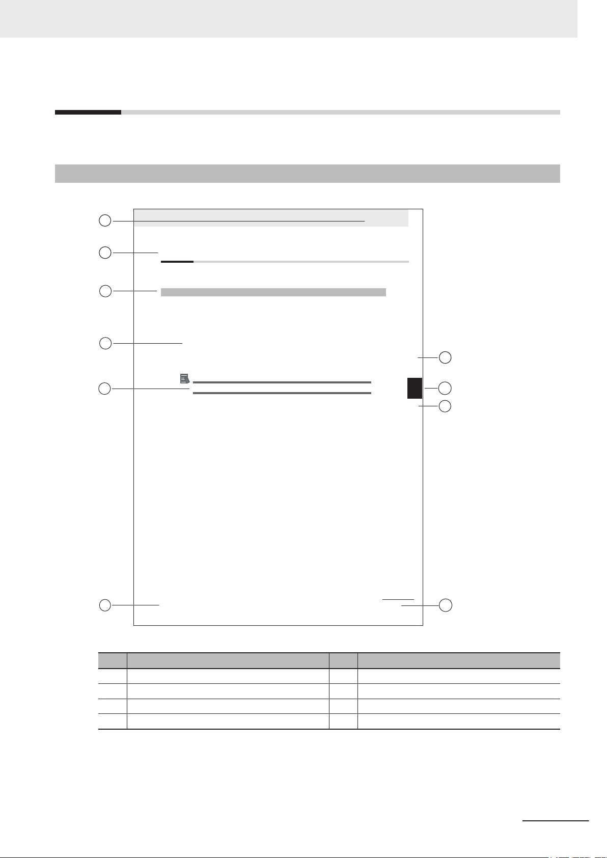
Page Structure
The following page structure is used in this manual.
Manual Information
Note: This illustration is provided as a sample. It will not literally appear in this manual.
Item Explanation Item Explanation
A Level 1 heading E Special Information
B Level 2 heading F Manual name
C Level 3 heading G Page tab with the number of the main section
D Step in a procedure H Page number
NY-series Industrial PC Operating Systems and Software Utilities Manual (W616)
7
Page 10

Manual Information
Special Information
Special information in this manual is classified as follows:
Precautions for Safe Use
Precautions on what to do and what not to do to ensure safe usage of the product.
Precautions for Correct Use
Precautions on what to do and what not to do to ensure proper operation and performance.
Additional Information
Additional information to read as required.
This information is provided to increase understanding or make operation easier.
Version Information
Information on differences in specifications and functionality between different versions.
8
NY-series Industrial PC Operating Systems and Software Utilities Manual (W616)
Page 11

Terms and Conditions Agreement
Terms and Conditions Agreement
Warranty and Limitations of Liability
WARRANTY
• The warranty period for the Software is one year from the date of purchase, unless otherwise
specifically agreed.
• If the User discovers defect of the Software (substantial non-conformity with the manual), and return
it to OMRON within the above warranty period, OMRON will replace the Software without charge by
offering media or download from OMRON’s website. And if the User discovers defect of media
which is attributable to OMRON and return it to OMRON within the above warranty period, OMRON
will replace defective media without charge. If OMRON is unable to replace defective media or
correct the Software, the liability of OMRON and the User’s remedy shall be limited to the refund of
the license fee paid to OMRON for the Software.
LIMITATION OF LIABILITY
• THE ABOVE WARRANTY SHALL CONSTITUTE THE USER’S SOLE AND EXCLUSIVE
REMEDIES AGAINST OMRON AND THERE ARE NO OTHER WARRANTIES, EXPRESSED OR
IMPLIED, INCLUDING BUT NOT LIMITED TO, WARRANTY OF MERCHANTABILITY OR
FITNESS FOR PARTICULAR PURPOSE. IN NO EVENT, OMRON WILL BE LIABLE FOR ANY
LOST PROFITS OR OTHER INDIRECT, INCIDENTAL, SPECIAL OR CONSEQUENTIAL
DAMAGES ARISING OUT OF USE OF THE SOFTWARE.
• OMRON SHALL HAVE NO LIABILITY FOR DEFECT OF THE SOFTWARE BASED ON
MODIFICATION OR ALTERNATION TO THE SOFTWARE BY THE USER OR ANY THIRD PARTY.
OMRON SHALL NOT BE RESPONSIBLE AND/OR LIABLE FOR ANY LOSS, DAMAGE, OR
EXPENSES DIRECTLY OR INDIRECTLY RESULTING FROM THE INFECTION OF OMRON
PRODUCTS, ANY SOFTWARE INSTALLED THEREON OR ANY COMPUTER EQUIPMENT,
COMPUTER PROGRAMS, NETWORKS, DATABASES OR OTHER PROPRIETARY MATERIAL
CONNECTED THERETO BY DISTRIBUTED DENIAL OF SERVICE ATTACK, COMPUTER
VIRUSES, OTHER TECHNOLOGICALLY HARMFUL MATERIAL AND/OR UNAUTHORIZED
ACCESS.
• OMRON SHALL HAVE NO LIABILITY FOR SOFTWARE DEVELOPED BY THE USER OR ANY
THIRD PARTY BASED ON THE SOFTWARE OR ANY CONSEQUENCE THEREOF.
NY-series Industrial PC Operating Systems and Software Utilities Manual (W616)
9
Page 12

Terms and Conditions Agreement
Application Considerations
APPLICABLE CONDITIONS
A USER SHALL NOT USE THE SOFTWARE FOR ANY PURPOSE THAT IS NOT PROVIDED IN
THIS MANUAL OR IN A RELATED HARDW
Suitability of Use
Omron Companies shall not be responsible for conformity with any standards, codes or regulations
which apply to the combination of the Product in the Buyer’s application or use of the Product. At
Buyer’s request, Omron will provide applicable third party certification documents identifying ratings
and limitations of use which apply to the Product. This information by itself is not sufficient for a
complete determination of the suitability of the Product in combination with the end product, machine,
system, or other application or use. Buyer shall be solely responsible for determining appropriateness
of the particular Product with respect to Buyer
application responsibility in all cases.
ARE USER'S MANUAL.
’s application, product or system. Buyer shall take
NEVER USE THE PRODUCT FOR AN APPLICATION INVOLVING SERIOUS RISK TO LIFE OR
PROPERTY OR IN LARGE QUANTITIES WITHOUT ENSURING THAT THE SYSTEM AS A WHOLE
HAS BEEN DESIGNED TO ADDRESS THE RISKS, AND THAT THE OMRON PRODUCT(S) IS
PROPERLY RATED AND INSTALLED FOR THE INTENDED USE WITHIN THE OVERALL
EQUIPMENT OR SYSTEM.
Programmable Products
• Omron Companies shall not be responsible for the user’s programming of a programmable Product,
or any consequence thereof.
• Omron Companies shall not be responsible for the operation of the user accessible operating sys-
tem (e.g. Windows, Linux), or any consequence thereof.
10
NY-series Industrial PC Operating Systems and Software Utilities Manual (W616)
Page 13

Disclaimers
Performance Data
Data presented in Omron Company websites, catalogs and other materials is provided as a guide for
the user in determining suitability and does not constitute a warranty. It may represent the result of
Omron’
formance is subject to the Omron’s Warranty and Limitations of Liability.
s test conditions, and the user must correlate it to actual application requirements. Actual per-
Change in Software Specifications
The software specifications and accessories may be changed at any time based on improvements and
other reasons.
Terms and Conditions Agreement
Errors and Omissions
Information presented by Omron Companies has been checked and is believed to be accurate; how-
ever, no responsibility is assumed for clerical, typographical or proofreading errors or omissions.
NY-series Industrial PC Operating Systems and Software Utilities Manual (W616)
11
Page 14

Safety Precautions
Safety Precautions
For NYB£ and NYP£ refer to the following manuals:
• NY-series Industrial Box PC Hardware User
• NY-series Industrial Panel PC Hardware User’s Manual (Cat. No. W555)
’s Manual (Cat. No. W553)
12
NY-series Industrial PC Operating Systems and Software Utilities Manual (W616)
Page 15

Precautions for Safe Use
For NYB£ and NYP£ refer to the following manuals:
• NY-series Industrial Box PC Hardware User
• NY-series Industrial Panel PC Hardware User’s Manual (Cat. No. W555)
’s Manual (Cat. No. W553)
Precautions for Safe Use
NY-series Industrial PC Operating Systems and Software Utilities Manual (W616)
13
Page 16

Precautions for Correct Use
Precautions for Correct Use
For NYB£ and NYP£ refer to the following manuals:
• NY-series Industrial Box PC Hardware User
• NY-series Industrial Panel PC Hardware User’s Manual (Cat. No. W555)
’s Manual (Cat. No. W553)
14
NY-series Industrial PC Operating Systems and Software Utilities Manual (W616)
Page 17

Regulations and Standards
Conformance to EU Directives
The Industrial PC complies with EU Directives. To ensure that the machine or device in which the In-
dustrial PC is used complies with EU Directives, the following precautions must be observed:
• The Industrial PC must be installed within a control panel.
• The Industrial PC that complies with EU Directives also conforms to the Common Emission Stand-
ard. Radiated emission characteristics (10-m regulations) may vary depending on the configuration
of the control panel used, other devices connected to the control panel, wiring, and other conditions.
You must therefore confirm that the overall machine or equipment in which the Industrial PC is used
complies with EU Directives.
• This is a Class A product (for industrial environments). In a residential environment, it may cause
radio interference. If radio interference occurs, the user may be required to take appropriate meas-
ures.
Regulations and Standards
Applicable Directive
EMC Directive
NY-series Industrial PC Operating Systems and Software Utilities Manual (W616)
15
Page 18

Regulations and Standards
Conformance to KC Certification
When you use this product in South Korea, observe the following precautions.
This product meets the electromagnetic compatibility requirements for business use. There is a risk of
radio interference when this product is used in home.
Conformance to UL and CSA Standards
Some Industrial PC Platform products comply with UL and CSA standards. If you use a product that
complies with UL or CSA standards and must apply those standards to your machinery or devices,
refer to this manual. This manual provides the application conditions for complying with the standards.
If the product is used in a manner not specified in the Instruction Sheet or in the product manuals then
the protection provided by the equipment may be impaired.
Software Licenses and Copyrights
This product incorporates certain third party software. The license and copyright information associat-
ed with this software is available at http://www.fa.omron.co.jp/nj_info_e/.
16
NY-series Industrial PC Operating Systems and Software Utilities Manual (W616)
Page 19

Related Manuals
The following manuals are related. Use these manuals for reference.
Related Industrial PC Manuals
This table contains the related manuals of Industrial PC products.
Related Manuals
Manual name
NY-series Industrial Box
PC Hardware
’
s Manual
User
(Cat. No.
W553)
NY-series Industrial Panel
PC Hardware
User’
s Manual
(Cat. No.
W555)
Cat.
No.
W553 NYB Learning all basic information about the
W555 NYP Learning all basic information about the
Model
num-
bers
Application Description
Industrial Box PC. This includes introductory information with features, hardware
overview, software overview, specifications, mounting, wiring, connecting, operating and maintaining the Industrial Box
PC.
Mainly hardware information is provided.
Industrial Panel PC. This includes introductory information with features, hardware overview, software overview, specifications, mounting, wiring, connecting, operating and maintaining the Industrial
Panel PC.
Mainly hardware information is provided.
An introduction to the Industrial
Box PC is provided along with
the following information:
• Overview
• Hardware
• Software
• Specifications
• Installation
• Operating Procedures
• Maintenance
An introduction to the Industrial
Panel PC is provided along with
the following information:
• Overview
• Hardware
• Software
• Specifications
• Installation
• Operating Procedures
• Maintenance
Industrial Monitor Manual
This table contains the related manual of the Industrial Monitor.
Manual
name
Industrial
Monitor
User’
s
Manual
NY-series Industrial PC Operating Systems and Software Utilities Manual (W616)
Cat.
No.
W554
Model numbers Application Description
• NYM12W-C1
££
• NYM15W-C1£
££
• NYM19W-C1£
££
Learning all basic information
£
about the Industrial Monitor
includes introductory information
with features, hardware overview,
specifications, mounting, wiring,
connecting, operating and maintaining the Industrial Monitor.
. This
An introduction to the Industrial
Monitor is provided along with
the following information:
• Overview
• Hardware
• Software
• Specifications
• Installation
• Operating Procedures
• Maintenance
17
Page 20
Terminology and Abbreviations
Terminology and Abbreviations
Industrial PC Platform
Term / Abbreviation Description
Industrial PC Platform An integrated range of OMRON products designed for use in any industrial applica-
tion that will benefit from advanced PC technology
Industrial Monitor An industrial monitor with a touchscreen as the user interface designed to work in
industrial environments
Industrial Panel PC An industrial PC with an integrated touchscreen monitor designed to work in indus-
trial environments
Industrial Box PC A box-shaped industrial PC including an OS designed to work in industrial environ-
ments
IPC Industrial PC
Sysmac OMRON’s brand name of the product family for the industrial automation equip-
ment
Software
Term / Abbreviation Description
ACPI Advanced Configuration and Power Interface protocol for operating systems
API Application Programming Interface
BIOS Basic Input Output System. The first software run by a PC when powered on.
Developer Any person involved with the development of software
DST Daylight Saving Time
EWF Enhanced Write Filter
FBWF File-Based Write Filter
IIoT Industrial Internet of Things
Linux An open source Operating System
MBR Master Boot Record
Merge module A module providing a standard method by which developers deliver shared Win-
MSDN Microsoft Developer Network
NUI Natural User Interface
OS Operating System
PLC Programmable Logic Controller
RTOS Realtime Operating System
SDK Software Development Kit
TCP/IP Transmission Control Protocol / Internet Protocol, a core member of the Internet
TPM Trusted Platform Module
VxWorks A Realtime Operating System designed by Wind River
Windows An Operating System designed by Microsoft
dows installer components and setup logic to their applications
protocol suite
18
NY-series Industrial PC Operating Systems and Software Utilities Manual (W616)
Page 21

Hardware
Term / Abbreviation Description
BMC Board Management Controller
CFast An SSD CFast storage device
CPU A Central Processing Unit is the hardware within a computer that executes the in-
DVI Digital Visual Interface
DVI-D A Digital Visual Interface with only Digital signals
DVI-I A Digital Visual Interface with Analog and Digital signals
Ethernet A network communication protocol used in TCP/IP network
HDD A Hard Disk Drive storage device
HMI A Human Machine Interface that facilitates machine operation and control
iMLC Industrial Multi-Level Cell type of SSD storage device
NYML NY Monitor Link interface with video signals and USB signals
PCIe The PCI Express is a high-speed computer bus standard called Peripheral Compo-
PoE Power over Ethernet
SATA The Serial AT Attachment is a serial bus interface primarily used with mass storage
SLC Single-Level Cell type of SSD storage device
SO-DIMM Small Outline Dual Inline Memory Module
SSD A Solid State Drive storage device
USB Universal Serial Bus
Terminology and Abbreviations
structions of a computer program
nent Interconnect Express
devices such as hard disk drives
NY-series Industrial PC Operating Systems and Software Utilities Manual (W616)
19
Page 22

W616-E2-02
Cat. No.
Revision code
Revision History
Revision History
A manual revision code appears as a suffix to the catalog number on the front and back covers of the
manual.
Revision code Date Revised content
02 July 2019 Updated Conformance to KC certification
01 May 2019
• First release of this software manual for Industrial PCs
NY
• All hardware information for the Box PC is available in
trial Box PC Hardware User’s Manual (Cat. No. W553)
• All hardware information for the Panel PC is available in NY-series In-
dustrial Panel PC Hardware User’s Manual (Cat. No. W555).
-series Indus-
20
NY-series Industrial PC Operating Systems and Software Utilities Manual (W616)
Page 23

Overview
This section provides general information about the Industrial PC.
1
1
1-1 Intended Use
1-2 Software Features ..........................................................................................1-3
1-3 ID Information Label....................................................................................... 1-4
1-4 Product Configuration ................................................................................... 1-5
1-4-1 Product Configuration Box PC........................................................................ 1-5
1-4-2 Product Configuration Panel PC..................................................................... 1-7
1-5 Overall Setup Procedure ...............................................................................1-9
.................................................................................................. 1-2
NY-series Industrial PC Operating Systems and Software Utilities Manual (W616)
1-1
Page 24

1 Overview
1-1
Intended Use
The Industrial PC is intended to be used in factory automation environments. This Industrial PC can
be configured with Windows, Linux or a realtime operating system (RTOS). Software utilties extend
the functionality and support the functional integration in custom software. It can be used with third
party software to serve as a powerful PC platform.
A user can access the Industrial PC for control, configuration and supervisory operations.
The Industrial PC can easily be integrated in manufacturing innovations like big data, NUI and IIoT.
The Industrial PC has a compact design that offers flexibility, expandability and easy maintenance for
applications in factory automation environments.
1-2
NY-series Industrial PC Operating Systems and Software Utilities Manual (W616)
Page 25

1 Overview
1-2 Software Features
1-2
Software Features
The Industrial PC provides the following software features:
• Operating Systems
The system can be delivered with and without an operating system.
• Software Utilities
A range of software utilities extends the functionality of the Industrial PC.
There are software utilities that provide:
• functional support like brightness adjustments.
• operator support like messages for the operator.
• technical support like status details for diagnosing and resolving problems.
• APIs for developers
Several APIs allow software developers to implement functionality of the Industrial PC in a custom
program.
1
NY-series Industrial PC Operating Systems and Software Utilities Manual (W616)
1-3
Page 26

1 Overview
1-3
ID Information Label
The ID information label contains the product configuration and other details on the specific configura-
tion of your Industrial PC.
For NYB£ and NYP£ refer to the following manuals:
• NY-series Industrial Box PC Hardware User’s Manual (Cat. No. W553)
• NY-series Industrial Panel PC Hardware User’s Manual (Cat. No. W555)
1-4
NY-series Industrial PC Operating Systems and Software Utilities Manual (W616)
Page 27
N Y B
1 2
3 4 5 6 7
1 Overview
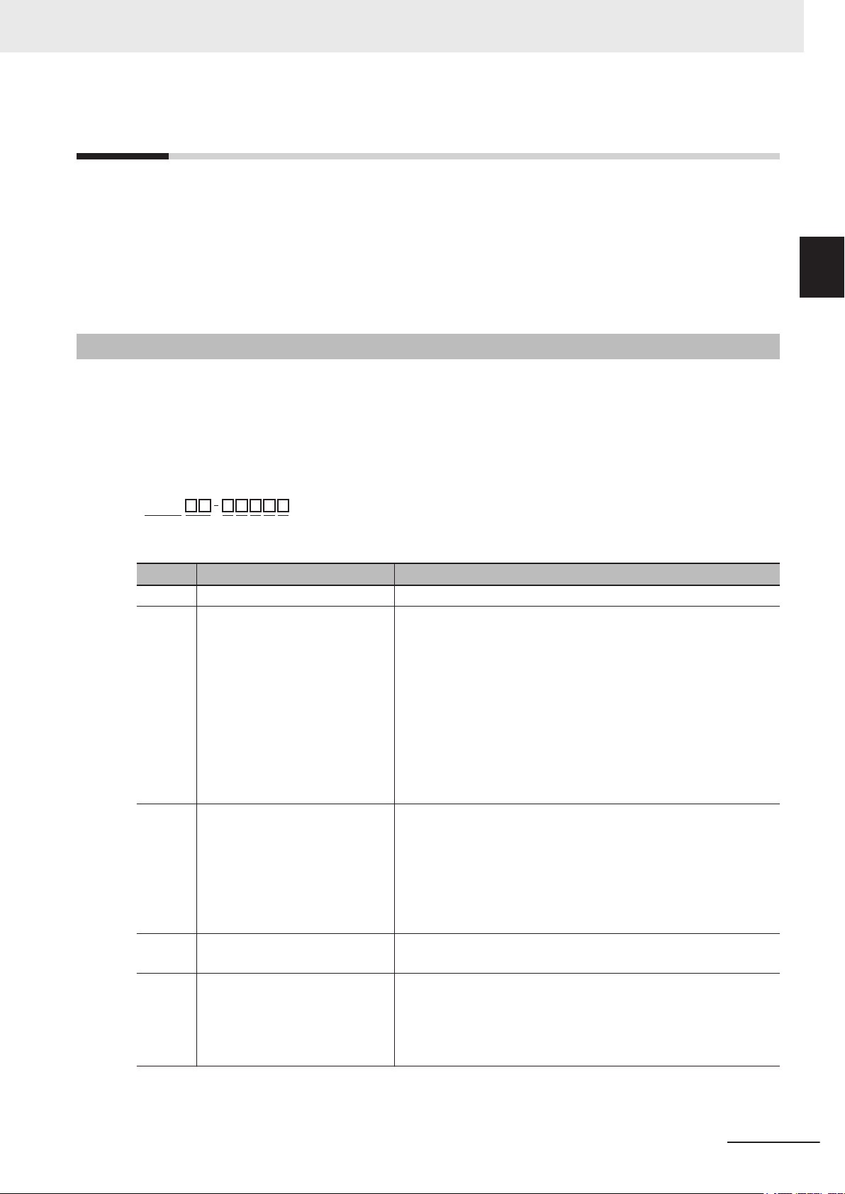
1-4 Product Configuration
1-4
1-4-1
Product Configuration
This section provides an overview of the product configurations available for the Industrial PCs.
The product configuration is visible in the model-ID that is mentioned on the ID information label of the
Industrial PC.
Refer to 1-4-1 Product Configuration Box PC on page 1-5 for Industrial Box PC details.
Refer to 1-4-2 Product Configuration Panel PC on page 1-7 for Industrial Panel PC details.
Product Configuration Box PC
This section provides an overview of the product configurations available for the Industrial Box PC.
The product configuration is visible in the model-ID that is mentioned on the ID information label of the
product.
The structure of the model-ID is: NYB££-£££££.
Each item in the model-ID has a specific meaning.
1
1-4-1 Product Configuration Box PC
Item Description Option / Description
1 Series name NYB: NY- series Industrial Box PC
2 Processor
3 Main memory 1: 2 GB, non-ECC
4 Expansion slots 0: None
5 Operating system 0: No Operating System
1C: Intel® Celeron® 2980U, 4th generation CPU
1E: Intel® Xeon® E3-1515M v5
6th generation CPU with active cooling
17: Intel®
2A: Intel® Atom® x5-E3940
2C: Intel® Celeron® 3965U, 7th generation CPU
25: Intel® Core™ i5-4300U, 4th generation CPU
35: Intel® Core™ i5-7300U, 7th generation CPU
2: 4 GB, non-ECC
3: 8 GB, non-ECC
4: 16 GB, non-ECC
5: 32 GB, non-ECC
C: 8 GB, ECC
D: 16 GB, ECC
1: 1 PCIe slot
1: Windows Embedded Standard 7 - 32 bit
2: Windows Embedded Standard 7 - 64 bit
3: Windows 10 IoT Enterprise 2016 L
4: Windows 10 IoT Enterprise 2019 L
Core™ i7-4700EQ,
4th generation CPU with active cooling
TSB - 64 bit
TSC - 64 bit
NY-series Industrial PC Operating Systems and Software Utilities Manual (W616)
1-5
Page 28

1 Overview
6 Storage 5: 64 GB, CFast iMLC
7 Optional interface 0: None
Item Description Option / Description
6: 128 GB, CFast iMLC
7: 256 GB, CFast iMLC
8: 32 GB, SSD SLC
9: 64 GB, SSD SLC
C: 320 GB, HDD
D: 500 GB, HDD
E: 1 TB, HDD
K: 128 GB, SSD iMLC
M: 500 GB, SSD iMLC
1: RS-232C
2: DVI-D
6: NY Monitor Link
9: Gb Ethernet
1-6
NY-series Industrial PC Operating Systems and Software Utilities Manual (W616)
Page 29

N Y P
1 2
3 4 5 6 7 8 9
10 11 12 13 14
1 Overview
1-4 Product Configuration
1-4-2
Product Configuration Panel PC
This section provides an overview of the product configurations available for the Industrial Panel PC.
The product configuration is visible in the model-ID that is mentioned on the ID information label of the
IPC.
The structure of the model-ID is: NYP££-£££££-££££££££.
Each item in the model-ID has a specific meaning.
Item Description Option / Description
1 Series name NYP: NY- series Industrial Panel PC
2 Processor
3 Main memory 1: 2 GB, non-ECC
4 Expansion slots 0: None
5 Operating system 0: No Operating System
6 Storage 5: 64 GB, CFast iMLC
7 Optional interface 0: None
1C: Intel® Celeron® 2980U, 4th generation CPU
17: Intel® Core™ i7-4700EQ,
4th generation CPU with active cooling
2A: Intel® Atom® x5-E3940
2C: Intel® Celeron®
25: Intel® Core™ i5-4300U, 4th generation CPU
35: Intel® Core™ i5-7300U, 7th generation CPU
2: 4 GB, non-ECC
3: 8 GB, non-ECC
4: 16 GB, non-ECC
5: 32 GB, non-ECC
C: 8 GB, ECC
D: 16 GB, ECC
1: 1 PCIe slot
1: Windows Embedded Standard 7 - 32 bit
2: Windows Embedded Standard 7 - 64 bit
3: Windows 10 IoT Enterprise 2016 L
4: Windows 10 IoT Enterprise 2019 L
6: 128 GB, CFast iMLC
7: 256 GB, CFast iMLC
8: 32 GB, SSD SLC
9: 64 GB, SSD SLC
C: 320 GB, HDD
D: 500 GB, HDD
E: 1 TB, HDD
K: 128 GB, SSD iMLC
M: 500 GB, SSD iMLC
1: RS-232C
2: DVI-D
6: NY Monitor Link
9: Gb Ethernet
3965U, 7th generation CPU
TSB - 64 bit
TSC - 64 bit
1
1-4-2 Product Configuration Panel PC
NY-series Industrial PC Operating Systems and Software Utilities Manual (W616)
1-7
Page 30

1 Overview
8 Display size
9 Display ratio W: Wide
10 Touchscreen C: Projected Capacitive Touch type
11 Frame type 1: Panel mounted
12 Material finish 0: Aluminum, painted black
13 Built-in options 0: None
14 Logo 0: OMRON
Item Description Option / Description
12: 12.1 inch model, 1280 x 800 pixels, 24 bit full color
(diagonal)
15: 15.4 inch model, 1280 x 800 pixels, 24 bit full color
19: 18.5 inch model, 1920 x 1080 pixels, 24 bit full color
1: Aluminum, Nickel plated
6: NY Monitor Link
2: Customization
1-8
NY-series Industrial PC Operating Systems and Software Utilities Manual (W616)
Page 31

1 Overview
1-5 Overall Setup Procedure
1-5
Overall Setup Procedure
This section gives the overall setup procedure for the Industrial PC.
This manual presents this information in the same order as the following setup procedure.
To setup the Industrial PC:
1 Familiarize yourself with the Industrial PC
• Refer to the sections Overview and Hardware of the Hardware manual.
For NYB
• NY-series Industrial Box PC Hardware User’s Manual (Cat. No. W553)
• NY-series Industrial Panel PC Hardware User’s Manual (Cat. No. W555)
• Refer to the information in this manual.
Specifically refer to the sections:
• Section 2 System Configurations on page 2-1
• Section 3 Software on page 3-1
• Section 4 Specifications on page 4-1
2 Install the IPC Hardware
Perform the procedures that are required to use the
nection with peripheral devices including a UPS.
Refer to the section Installation in the Hardware manual..
£ and NYP£ refer to the following manuals:
Industrial PC
such as installation, and con-
1
3 Setup the IPC
Install and configure the operating system, the software support utilities and the UPS software.
Item Remark Reference
Operating system settings Follow the procedure for 'First
time startup'
UPS settings Make the required UPS settings The applicable UPS Manual
Industrial Monitor settings Adjust the brightness and con-
trast of the monitor
The applicable Hardware Manual, see step 1.
3-4 Industrial Monitor Utility on
page 3-1
1
4 Operate the IPC
Use the operating procedures to operate the Industrial PC
Refer to the sections Operating Procedures in this manual and in the Hardware manual.
The setup of the Industrial PC is finished.
The section 'Maintenance' contains preventive and corrective maintenance information.
Refer to the section Maintenance in this manual and in the Hardware manual.
.
NY-series Industrial PC Operating Systems and Software Utilities Manual (W616)
1-9
Page 32

1 Overview
1-10
NY-series Industrial PC Operating Systems and Software Utilities Manual (W616)
Page 33

2
2
System Configurations
This section provides an overview of the system configurations for the Industrial PC.
2-1 Configuration for NYB and NYP
.................................................................... 2-2
NY-series Industrial PC Operating Systems and Software Utilities Manual (W616)
2-1
Page 34

NYB and NYP-series IPC
Ethernet
SD Memory
Card
PCIe Card
HDD / SSD
RS-232C
DVI USB
Ports
NYML
Operating System
&
Software Utilities
&
APIs
2 System Configurations
2-1
Configuration for NYB and NYP
The Industrial PC supports the following software configurations.
The operating system is the foundation for your software environment. The operating system manages
the IPC hardware and supplies an interface for the users.
Refer to 3-1 Windows Operating System on page 3-3 for details.
Support software is a collection of software utilities to support and extend the functionality of your In-
dustrial PC.
Refer to 3-2 Overview IPC Support Software for Windows on page 3-4 for details.
APIs are available for software developers that want to implement PC functionality in custom software
applications.
Refer to 3-9 Software for Developers on page 3-32 for details.
2-2
NY-series Industrial PC Operating Systems and Software Utilities Manual (W616)
Page 35

Software
3
3
This section provides software information for the Industrial PC.
3-1 W
3-2 Overview IPC Support Software for Windows............................................. 3-4
3-3 Industrial PC Support Utility ........................................................................3-5
3-4 Industrial Monitor Utility ............................................................................. 3-11
3-5 Industrial Monitor Brightness Utility ......................................................... 3-17
3-6 Rescue Disk Creator ....................................................................................3-19
3-7 Industrial PC Tray Utility ............................................................................. 3-25
indows Operating System.......................................................................... 3-3
3-1-1 Determine Your Version of the Windows Operating Systems......................... 3-3
3-3-1 Industrial PC Support Utility Overview............................................................ 3-6
3-3-2 Product Information Tab................................................................................. 3-7
3-3-3 System Status Tab.......................................................................................... 3-8
3-3-4 Machine Controller Tabs ................................................................................. 3-9
3-3-5 Compatibility ................................................................................................... 3-9
3-3-6 Installation....................................................................................................... 3-9
3-3-7 Startup ............................................................................................................ 3-9
3-3-8 Logging ......................................................................................................... 3-10
3-4-1 Industrial Monitor Utility Overview .................................................................3-11
3-4-2 Compatibility ................................................................................................. 3-15
3-4-3 Installation..................................................................................................... 3-15
3-4-4 Startup .......................................................................................................... 3-15
3-4-5 Configuration ................................................................................................ 3-16
3-4-6 Messages ..................................................................................................... 3-16
3-4-7 Logging ......................................................................................................... 3-16
3-5-1 Industrial Monitor Brightness Utility ............................................................. 3-17
3-5-2 Compatibility ................................................................................................. 3-17
3-5-3 Installation..................................................................................................... 3-18
3-5-4 Startup .......................................................................................................... 3-18
3-5-5 Configuration ................................................................................................ 3-18
3-5-6 Logging ......................................................................................................... 3-18
3-6-1 Rescue Disk Creator Overview..................................................................... 3-19
3-6-2 Compatibility ................................................................................................. 3-20
3-6-3 Installation..................................................................................................... 3-20
3-6-4 Startup .......................................................................................................... 3-21
3-6-5 Messages ..................................................................................................... 3-21
3-7-1 Industrial PC Tray Utility Overview ............................................................... 3-25
3-7-2 Features........................................................................................................ 3-25
3-7-3 Menu............................................................................................................. 3-26
NY-series Industrial PC Operating Systems and Software Utilities Manual (W616)
3-1
Page 36

3 Software
3-7-4 About the Industrial PC Tray Utility............................................................... 3-26
3-7-5 Status Indicators on Icons ............................................................................ 3-27
3-7-6 Compatibility ................................................................................................. 3-27
3-7-7 Installation..................................................................................................... 3-27
3-7-8 Startup .......................................................................................................... 3-28
3-8 Power Attendant Lite Utility ........................................................................3-29
3-8-1 Power Attendant Lite Utility Overview........................................................... 3-29
3-8-2 Features........................................................................................................ 3-29
3-8-3 Compatibility ................................................................................................. 3-29
3-8-4 Installation..................................................................................................... 3-30
3-8-5 Configuration ................................................................................................ 3-30
3-9 Software for Developers.............................................................................. 3-32
3-9-1 Overview IPC Developer Software for Windows .......................................... 3-32
3-9-2 Industrial PC System API ............................................................................ 3-33
3-9-3 Industrial Monitor API .................................................................................. 3-34
3-2
NY-series Industrial PC Operating Systems and Software Utilities Manual (W616)
Page 37

3 Software
3-1
3-1-1
Windows Operating System
This section provides an overview of Windows Operating System information.
Determine Your Version of the Windows Operating Systems
This section provides methods to find version details of your Windows Operating System.
Windows 7
Windows 7 is only compatible with 4th generation CPUs.
Refer to 1-4-2 Product Configuration Panel PC on page 1-7 for CPU details.
T
o determine your version of the Windows Operating System:
1 Select the Start Button.
2 Enter System Information in the search box.
3-1 Windows Operating System
3
3-1-1 Determine Your Version of the Windows Operating Systems
3 Select System Information in the pop-up that appears.
Windows 10
To determine your version of the Windows Operating System:
1 Select the Search Button.
2 Enter System Information in the search box.
3 Select System Information in the pop-up that appears.
An overview of your System Information will appear
details.
, including the Windows Operating System
NY-series Industrial PC Operating Systems and Software Utilities Manual (W616)
3-3
Page 38

3 Software
3-2
Overview IPC Support Software for Windows
This section gives an overview of the software utilities available for all Industrial PC Platform products
with a Windows operating system.
Product Software utility
Industrial Monitor Industrial Monitor Utility
*1
Industrial Monitor Brightness Utility
Industrial PC T
Industrial Box PC Industrial PC Support Utility
Industrial PC T
Rescue Disk Creator
Industrial Panel PC Industrial Monitor Utility
Industrial Monitor Brightness Utility
Industrial PC Support Utility
Industrial PC T
Rescue Disk Creator
*1. Included in the Industrial Monitor Utility installer
*2. Included in the Industrial PC Support Utility installer
*3. Together with the Industrial PC Tray Utility also Microsoft .NET Framework 4.6 is installed.
ray Utility
ray Utility
ray Utility
*1*2*3
*2*3
*1
*1*2*3
*1
Select and download the required utilities from the OMRON website.
Additional Information
An internet connection is required to install support software.
3-4
NY-series Industrial PC Operating Systems and Software Utilities Manual (W616)
Page 39

3 Software
3-3
Industrial PC Support Utility
This section provides an overview of the Industrial PC Support Utility.
3-3 Industrial PC Support Utility
3
NY-series Industrial PC Operating Systems and Software Utilities Manual (W616)
3-5
Page 40

G
EDB
A
C
F
3 Software
3-3-1
Industrial PC Support Utility Overview
The Industrial PC Support Utility is a software utility to assist in diagnosing and resolving problems of
the Industrial PC.
Item Description Details
A Production Data Tab
B System Status Tab
C Machine Controller Tabs A series of tabs that is only availabel for an Industrial PC with Machine
D Tab details Details of the selected Tab page.
E Language Selector Select to display and choose the UI language of the Industrial PC Support
F Close Button Close the Industrial PC Support Utility.
G Update Screen Button Use this button to retrieve updated values from the Industrial PC.
Select to display Production Data details in the Tab details area
Refer to 3-3-2 Product Information Tab on page 3-7
Select to display System Status details in the Tab details area
Refer to 3-3-3 System Status Tab on page 3-8 for details.
Automation Control Software. Refer to
page 3-9 for details.
Utility.
.
for details.
.
3-3-4 Machine Controller Tabs on
3-6
NY-series Industrial PC Operating Systems and Software Utilities Manual (W616)
Page 41

3 Software
3-3-2
Product Information Tab
The Production Data tab displays generic Industrial PC information. These are e.g. Model name, Lot
number
trial PC Support Utility and Industrial PC System API).
, Serial number
, Hardware version, BIOS version, BMC version, and software versions (Indus-
3-3 Industrial PC Support Utility
3
3-3-2 Product Information Tab
• Model Name is the configuration code of this model.
Refer to 1-4-2 Product Configuration Panel PC on page 1-7 for details.
•
BMC Version is the firmware version of the Board Management Controller.
Values are not updated automatically. Select the Update Screen Button to display the latest values.
NY-series Industrial PC Operating Systems and Software Utilities Manual (W616)
3-7
Page 42

3 Software
3-3-3
System Status Tab
The System Status tab displays actual states and diagnostic information like internal temperature, fan
revolution, battery and power supply status.
A status that requires attention is indicated with a red bar
.
Item Description
Internal Temperature The average CPU temperature.
Fan Revolution
*1
The actual rotation speed for each fan in revolutions per minute (r/min).
• First number = rotation speed of fan located closest to Power button.
• Second number = rotation speed of fan located closest to battery.
Fan Status
*2
The target speed for the fans is dynamically set based on the CPU temperature. The
target speed is compared with the actual fan speed.
indicates both fans are running on the target speed.
• OK
• Low revolution speed indicates one or both fans do not reach the target speed.
Clean the fans and replace the Fan Unit if the problem persists.
Battery Status The battery status.
• OK indicates the battery is full.
• Low indicates the battery voltage is low. Replace the battery.
Power Supply The power supply status is determined by the UPS and reported to the IPC via the I/O
connector.
• NormalPowerSupply indicates the IPC is powered by the 24V power supply.
• UPS Power Supply indicates that there is no power from the 24V power supply
and the IPC runs on battery power from the UPS.
*1. The Fan Revolution will always show 0 (r/min) / 0 (r/min) for fanless models
Refer to 1-4-2 Product Configuration Panel PC on page 1-7 for fan details.
*2. The Fan Status will always show OK for fanless models
3-8
Values are not updated automatically. Select the Update Screen Button to display the latest values.
NY-series Industrial PC Operating Systems and Software Utilities Manual (W616)
Page 43

3 Software
3-3-4
3-3-5
3-3-6
Machine Controller Tabs
The Industrial PC with Machine Automation Control Software has additional tabs available.
Examples are:
Controller Status, to display operation mode and current errors.
•
•
Controller Operation, to change operating mode or backup / restore the controller.
• Network Setting, to display and change network settings
• Virtual SD Memory Card Settings, to change the Virtual SD Memory Card Settings. .
These Machine Controller tabs are only relevant for an Industrial PC with Machine Automation Control
Software. Refer to NY-series IPC Machine Controller Industrial Panel PC / Industrial Box PC Setup
User’s Manual (Cat. No. W568) for details.
Compatibility
This software utility can be used on an IPC with Windows 7 or higher.
Installation
The Industrial PC Support Utility is pre-installed on the Industrial PC if it comes with a Windows oper-
ating system installed.
Download the
Industrial PC Support Utility
the OMRON website if reinstallation is required.
from
3-3 Industrial PC Support Utility
3
3-3-4 Machine Controller Tabs
3-3-7
Startup
The Industrial PC Support Utility can be started from:
Windows Start Menu
•
Select
• Industrial PC Tray Utility
• Windows desktop shortcut
OMRON and then Industrial PC Support Utility.
NY-series Industrial PC Operating Systems and Software Utilities Manual (W616)
3-9
Page 44

3 Software
3-3-8
Logging
There is logging in the Windows event log of the following utilities:
Industrial Monitor Utility
•
In the Windows Event V
• Industrial Monitor Brightness Utility
In the Windows Event Viewer filter for event source IndMonService.
• Industrial PC Support Utility
In the Windows Event Viewer filter for event source IPCServiceHost or OMRON Industrial PC
Support Utility.
Additional Information
Refer to 7-2-4 Windows Event V
iewer filter for event source IndMonService.
iewer on page 7-29 for the logged messages.
3-10
NY-series Industrial PC Operating Systems and Software Utilities Manual (W616)
Page 45

A
E
F
G
I
J
H
B
C
D
3 Software
3-4
3-4-1
Industrial Monitor Utility
This section provides an overview of the Industrial Monitor Utility.
Industrial Monitor Utility Overview
The Industrial Monitor Utility provides a user interface to control settings and display details of con-
nected Industrial Monitors.
3-4 Industrial Monitor Utility
3
3-4-1 Industrial Monitor Utility Overview
Item Description Details
A Connected Monitors
Product Information Provides details of the selected Industrial Monitor.
B
Version Information Provides version details of Industrial Monitor Utility software and firmware
C
D Monitor Settings Provides several setting adjustments to control the operation of the selected
Backlight Brightness Ad-
E
justment
F Logo Brightness Adjust-
ment
G Status Brightness Adjust-
ment
Touch Input Settings Provides details about the touch settings.
H
*2
I Advanced Settings Provides access to defaults and relevant Windows settings.
J Standard windows but-
tons
*1. The Industrial Monitor Utility scans the connected USB devices and shows a list of connected monitors. If an
Industrial Monitor is not connected with the USB cable, it will not be found.
Shows a list of the connected Industrial Monitors.*1 Select one
Monitor in the list to display the Monitor Details. When selected the LED Indicators of the selected monitor will flash during 3 seconds.
Refer to Product Information on page 3-12 for details.
details of the connected monitor.
Refer to
Industrial Monitor.
Use the slider to control the brightness of the selected Industrial Monitor.
Use the slider to control the brightness of the Logo LED.
Use the slider to control the brightness of the Status LED Indicator on the
monitor.
Refer to Touch Input Settings
Refer to Advanced Settings on page
Version Information on page 3-12 for details.
on page 3-13 for details.
3-14 for details.
Industrial
• OK button. Applies changes and closes the window
• Cancel button. Exits the utility
• Apply button. Applies the changes,
NY-series Industrial PC Operating Systems and Software Utilities Manual (W616)
3-11
Page 46

3 Software
*2. With a very low backlight brightness setting (15%-0%) the displayed information might not be visible in an envi-
The Product Information part supplies details of the selected connected monitor.
ronment with high ambient light conditions. This prevents brightness adjustments with the Industrial Monitor Utility.
Additional Information
To adjust the backlight brightness when the brightness setting is set too low:
• Bring the IPC in a low ambient light environment
• Lighten the display with a bright flashlight
Product Information
Version Information
The Version Information part supplies version details of the software and of the selected monitor.
Software details:
• The version of the Industrial Monitor Utility
The version of the Industrial Monitor API
•
Monitor details:
• The Hardware version of the monitor
• The version of the Firmware Software installed on the monitor
• The version of the Touch Firmware installed on the monitor
3-12
NY-series Industrial PC Operating Systems and Software Utilities Manual (W616)
Page 47

3 Software
Touch Input Settings
The Touch Input Settings display the actual settings.
• Point
Set to Single the monitor accepts only one touch point.
Set to Multiple allows more touch points simultaneously.
Water Detection
•
When enabled then a message will appear to inform the user when water is detected.
When disabled then no message will appear when water is detected.
• Mouse Emulation
When mouse emulation is enabled the Point setting is disabled and Press and Hold is enabled.
When mouse emulation is disabled the Point setting is enabled and the Press and Hold is disabled.
3-4 Industrial Monitor Utility
3
3-4-1 Industrial Monitor Utility Overview
Additional Information
Do not activate mouse emulation when using multiple industrial monitors in combination with
extended mode.
• Press and Hold
When enabled then a right-click mouse action occurs when holding a touch.
When disabled then holding the touch does not trigger the right-click mouse action.
NY-series Industrial PC Operating Systems and Software Utilities Manual (W616)
3-13
Page 48

3 Software
Advanced settings gives access to the factory settings and shortcuts to relevant Window settings.
• Restore Factory Defaults button
•
• Pen and Touch
Advanced Settings
Resets all settings of the Industrial Monitor
Tablet PC Settings
Opens the ‘Tablet PC Settings’-dialog of Windows.
Opens the ‘Pen and Touch’-dialog of Windows.
to the factory defaults.
3-14
NY-series Industrial PC Operating Systems and Software Utilities Manual (W616)
Page 49

3 Software
3-4-2
3-4-3
Compatibility
This monitor utility can be used on any PC that is connected to an OMRON Industrial Monitor.
This monitor utility can be used with:
Windows 10
•
•
Windows 7
Additional Information
This monitor utility does not support 3rd party monitors.
Installation
The Industrial Monitor Utility is pre-installed on the Industrial PC if it comes with a Windows operating
system installed.
Download the
another Industrial PC.
The Industrial Monitor Utility is installed onto Windows, and can be accessed via the Windows start
menu and the
trial PC Tray Utility.
Industrial Monitor Utility
Industrial PC Tray Utility. Installing the Industrial Monitor Utility will also install the Indus-
the OMRON website for reinstallation or for installation on
from
3-4 Industrial Monitor Utility
3
3-4-2 Compatibility
3-4-4
Additional Information
Refer to 3-7 Industrial PC Tray Utility
on page 3-25 for Industrial PC Tray Utility details.
Startup
The Industrial Monitor Utility can be started from:
Windows Start Menu.
•
Select
• Industrial PC Tray Utility
Omron and then Industrial Monitor Utility.
NY-series Industrial PC Operating Systems and Software Utilities Manual (W616)
3-15
Page 50

3 Software
3-4-5
3-4-6
Configuration
The Industrial Monitor Utility can be configured with following options:
Configuration item Description
Language Follows the Windows language configuration when that language is supported for the
Industrial Monitor Utility. The default language English (EN-US) will be used if the language configured in Windows is not supported.
Monitor identification
If enabled, the Status LED indicator on the selected Industrial Monitor will flash for 3
seconds.
To enable:
Open the Windows registry key HKEY_LOCAL_MACHINE\SOFTWARE
1.
\Wow6432Node\Omron\IPC\MonitorConfiguration
2. Set the registry value Indicate to value True.
Messages
The Industrial Monitor Utility can use the Industrial PC Tray Utility to display following messages:
Message
type
Info Connected A new monitor connected
Warning Not Connected Monitor disconnected
Warning Video Disconnected DVI cable disconnected or NY Monitor Link
Warning Serial number: x
Water detected on a monitor
ouch may be rejected
T
Warning No Signal DVI cable connected but no signal detected
Message Description
• USB cable connected
• Monitor powered ON
• USB cable disconnected
• Monitor powered OFF
cable disconnected
Water is detected on monitor x
3-4-7
3-16
Logging
There is logging in the Windows event log of the following utilities:
• Industrial Monitor Utility
In the Windows Event V
• Industrial Monitor Brightness Utility
In the Windows Event Viewer filter for event source IndMonService.
• Industrial PC Support Utility
In the Windows Event Viewer filter for event source IPCServiceHost or OMRON Industrial PC
Support Utility.
Additional Information
Refer to 7-2-4 Windows Event V
iewer filter for event source IndMonService.
iewer on page 7-29 for the logged messages.
NY-series Industrial PC Operating Systems and Software Utilities Manual (W616)
Page 51

A
B
3 Software
3-5
3-5-1
Industrial Monitor Brightness Utility
This section provides an overview of the Industrial Monitor Brightness Utility.
Industrial Monitor Brightness Utility
The Industrial Monitor Brightness Utility is a software utility that allows you to control the brightness of
the screen backlight of all connected Industrial Monitors.
3-5 Industrial Monitor Brightness Utility
3
3-5-1 Industrial Monitor Brightness Utility
3-5-2
Item Description Details
A Backlight brightness slider Use the slider to control the display brightness of all connected Industrial
Monitors.
B Industrial Monitor Utility Button to start the Industrial Monitor Utility.
With a very low backlight brightness setting (15%-0%) the displayed information might not be visible in
an environment with high ambient light conditions. This prevents brightness adjustments with the In-
dustrial Monitor Brightness Utility
Additional Information
To adjust the backlight brightness when the brightness setting is set too low:
• Bring the IPC in a low ambient light environment
Lighten the display with a bright flashlight
•
.
Compatibility
This monitor utility can be used on any PC that is connected to an OMRON Industrial Monitor.
This monitor utility can be used with:
• Windows 10
Windows 7
•
NY-series Industrial PC Operating Systems and Software Utilities Manual (W616)
3-17
Page 52

3 Software
Additional Information
This monitor utility does not support 3rd party monitors.
3-5-3
3-5-4
Installation
The Industrial Monitor Brightness Utility is pre-installed on the Industrial PC if it comes with a Windows
operating system installed.
Installation of the Industrial Monitor Brightness Utility
Utility.
Download the
another PC with a compatible operating system.
The Industrial Monitor Brightness Utility
dows start menu and the Industrial PC Tray Utility. Installing the Industrial Monitor Utility will also in-
stall the Industrial PC Tray Utility.
Additional Information
Refer to 3-7 Industrial PC Tray Utility
Industrial Monitor Utility from
the OMRON website for reinstallation or for installation on
is installed onto Windows, and can be accessed via the Win-
on page 3-25 for Industrial PC Tray Utility details.
is part of the installation of the Industrial Monitor
Startup
Start the Industrial Monitor Brightness Utility from the Industrial PC Tray Utility or from the Windows
Start Menu (select Omron and then Industrial Monitor Brightness Utility
).
3-5-5
3-5-6
Additional Information
Refer to 3-7 Industrial PC Tray Utility
on page 3-25 for Industrial PC Tray Utility details.
Configuration
Configuration is not required. This Industrial Monitor Brightness Utility will detect and support all con-
nected NY
-series
Industrial Monitors.
Logging
There is logging in the Windows event log of the following utilities:
Industrial Monitor Utility
•
In the Windows Event V
• Industrial Monitor Brightness Utility
In the Windows Event Viewer filter for event source IndMonService.
• Industrial PC Support Utility
In the Windows Event Viewer filter for event source IPCServiceHost or OMRON Industrial PC
Support Utility.
iewer filter for event source IndMonService.
3-18
Additional Information
Refer to 7-2-4 Windows Event V
NY-series Industrial PC Operating Systems and Software Utilities Manual (W616)
iewer on page 7-29 for the logged messages.
Page 53

B
C
E
F
D
A
3 Software
3-6
3-6-1
Rescue Disk Creator
This section provides an overview of the Rescue Disk Creator.
3-6 Rescue Disk Creator
Rescue Disk Creator Overview
The Rescue Disk Creator creates a Rescue Disk.
A Rescue Disk is a disk with the Rescue Disk Utility; this is the software that performs the system
backup and system restore procedures.
3
3-6-1 Rescue Disk Creator Overview
Item Description Details
A Explanation area Information about the utility and the backup.
In the right bottom corner messages are displayed when applicable.
B Target disk selection Selection of the disk that will become the Rescue Disk.
C Create Rescue Disk Button Start the Rescue Disk creation.
D Show non-removable disks Check the box to display not only the removable storage devices
but also the non-removable (internal) storage devices and USB
Flash Drives and other USB storage devices.
E Creation progress bar Display the progress of the Rescue Disk creation.
F Close Button Close the Rescue Disk Creator.
Additional Information
• Refer to Create a System Backup with the Rescue Disk on page 7-5 for system backup
details.
•
Refer to Restore a System Backup with the Rescue Disk on page 7-21 for system restore
details.
NY-series Industrial PC Operating Systems and Software Utilities Manual (W616)
3-19
Page 54

3 Software
3-6-2
3-6-3
Compatibility
This software utility can be used on the IPC but also on any other PC with one of the following operat-
ing systems:
Windows 10
•
•
Windows 7
Installation
The Rescue Disk Creator is preinstalled on the Industrial PC if it comes with a Windows operating sys-
tem installed.
Use the following procedure to reinstall the Rescue Disk Creator:
1 Use Windows Explorer to examine the local disk C.
2 Open the Rescue Disk folder (This PC\Local Disk(C:)\Program Files (x86)\OMRON\Industrial
PC\Rescue Disk) and activate the installer file setup.exe.
A progress bar will visualize the extraction process and then a language selection window
opens.
3 Select your language and then select OK.
The installer window opens.
4 Follow the installer steps to complete the Rescue Disk Creator installation.
The Rescue Disk Creator is installed and available in the OMRON folder in the Windows Start Menu.
3-20
NY-series Industrial PC Operating Systems and Software Utilities Manual (W616)
Page 55

3 Software
3-6-4
Startup
To manually start the Rescue Disk Creator:
1 Locate the Rescue Disk Creator using the Windows Start
2 Use the option Run as administrator
Additional Information
The procedure to use Run as administrator is:
• For Windows 10 using the Start
Rightclick the Rescue Disk Creator, select More and then Run as administrator.
• For Windows 10 using Search:
Rightclick the Rescue Disk Creator in the search results and select Run as administrator.
• For Windows 7 using the Start menu or Search:
Rightclick the Rescue Disk Creator and select Run as administrator.
to start the Rescue Disk Creator.
menu:
3 Follow the on-screen instructions to complete the rescue disk.
Use a USB storage device with a capacity of at least the Windows partition size + 16 GB. The
recommended minimum read/write speed is 190 MB/s.
A Rescue Disk is created by the Rescue Disk Creator
.
menu or the Windows search box.
3-6 Rescue Disk Creator
3
3-6-4 Startup
3-6-5
Messages
The Rescue Disk Creator creates a rescue disk in two steps:
1. Format the target disk
2. Copy the rescue disk image to the target disk
Messages can inform the user of an error when applicable.
Refer to Messages Creating the Rescue Disk on page 3-22
Use the rescue disk to create a backup or restore your disk.
Messages can inform the user of a backup or restore error when applicable.
Refer to Messages Using the Rescue Disk on page 3-23 for details.
for details.
NY-series Industrial PC Operating Systems and Software Utilities Manual (W616)
3-21
Page 56

3 Software
The Rescue Disk Creator can display the following messages:
Messages Creating the Rescue Disk
Message
type
Error Creation progress: Failed to format the disk.
Reason:
Message Description
• Access denied
• Call canceled
• Call cancellation request too late
• Cluster size is beyond 32 bits
• Cluster size is too large
• Cluster size is too small
• Incompatible media in drive
• Invalid volume label
• Input/Output (I/O) error
• No media in drive
• Unable to quick format
• Unknown error
• Unsupported file system
• V
olume lock failed
olume is not mounted
• V
• Volume is too large
• Volume is too small
• Volume write protected
Error Creation progress: Failed to copy image to
rescue disk.
Reason:
• Unable to revoke access to the disk
• Unable to revoke access to the drive
• Disk write failed
• Unable to dismount the drive
• Invalid drive
• Unable to obtain exclusive access to the
drive
• The disk could not be accessed
• The drive could not be accessed
• Unable to revoke exclusive access to the
drive
The mentioned reason prevented formatting of
the connected storage device.
Ensure the connected storage device:
• Is not write protected or read-only
• Has a cluster size too small or more than
the maximum 32 bits
• Has a valid volume label
• Has suf
rescue disk utility and a full system backup
The mentioned reason prevented copying the
image to the connected storage device.
Ensure the connected storage device:
ficient storage capacity to store the
• Is not used by other programs
• Is not write protected or read-only
3-22
To solve an error:
1. Check that the correct target disk was selected.
2. Check that the target disk has sufficient storage capacity to store the rescue disk utility and a full
system backup
3. If the storage device is removable, check that it is inserted properly and is of the correct type.
4. Check whether the storage device is write protected. SD Memory Cards often have a small me-
chanical write protection switch on them.
5. Check that the user has the necessary access rights for the target disk.
6. Check that the Rescue Disk Creator is running "As Administrator".
NY-series Industrial PC Operating Systems and Software Utilities Manual (W616)
Page 57

7. Check that no other applications are using the target disk.
8. Retry the operation with the same target disk.
9. Retry the operation with a different target disk.
3 Software
10. Restart the IPC and then retry the operation.
11. If the issue persists, contact your OMRON representative.
Messages Using the Rescue Disk
Using the Rescue Disk the rescue disk utility can display the following error messages:
Error ID Message
10
11
12 Cannot allocate the partition for storing backup data. There may be a problem with the target
13 Cannot create a partition for storing backup data. There may be a problem with the target USB
14 The partition for storing backup data cannot be identified. There may be a problem with the target
15 The partition for storing backup data cannot be prepared for use. There may be a problem with
16 Unable to identify an Omron Industrial PC. Power cycle the system using the power connector,
17 Unable to identify an Omron Industrial PC. Power cycle the system using the power connector,
18
19
20 Cannot mount the partition for storing backup data. There may be a problem with the target USB
21
22
23 Cannot create a backup. An Omron NY-series Industrial PC has not been detected. Please con-
24 Cannot restore the backup. An Omron NY-series Industrial PC has not been detected. Please
25 Cannot find a destination device. Please ensure that there is an SSD or HDD inserted in the IPC
26 Cannot find the Rescue Disk medium. Please ensure the Rescue Disk USB device is connected
27 Cannot mount Windows partition. Please ensure that you have a functional Windows system be-
28 Cannot restore. The backup of the Boot partition is corrupted
Backup creation of *1partition failed. Please try again or contact an Omron service representative
if the problem persists
Restore action of *1partition failed. Please try again or contact an Omron service representative if
the problem persists
USB device. Create the Rescue Disk utility on another USB device and try again
device. Create the Rescue Disk utility on another USB device and try again
USB device. Create the Rescue Disk utility on another USB device and try again
the target USB device. Create the Rescue Disk utility on another USB device and try again
then try again
then try again
Backup creation of *1partition failed. Please try again or contact an Omron service representative
if the problem persists
Restore action of *1partition failed. Please try again or contact an Omron service representative if
the problem persists
device. Create the Rescue Disk utility on another USB device and try again
Failed creating *1partition verification files. Please try again or contact an Omron service representative if the problem persists
Failed to verify *1partition backup files. Please try again or contact an Omron service representative if the problem persists
tact an Omron service representative
contact an Omron service representative
to the Industrial PC, then restart the system and try again
fore creating a backup
3-6 Rescue Disk Creator
3
3-6-5 Messages
NY-series Industrial PC Operating Systems and Software Utilities Manual (W616)
3-23
Page 58

3 Software
*1. The partition name will be indicated. Examples are 'Boot partition' or 'Master Boot Record' .
Error ID Message
29 Cannot deploy OSB due to an invalid Boot partition. Please perform a restore operation of the
complete MBR and Boot partition and try again
30 OSB deployment was unsuccessful. Please restart the Rescue Disk utility and try again
31 Multiple Rescue Disk media detected. Ensure there is only a single Rescue Disk USB device
connected to the Industrial PC, then reboot the system and try again
32 Cannot create backup records data due to missing OSB data
33 Cannot create backup records due to missing NX data
34 Cannot create backup records due to a missing Boot partition
35 Cannot find a source device. Please ensure that there is an SSD or HDD inserted in the IPC
36 Multiple disk with windows partitions detected. Please ensure there is only one SSD or HDD in-
serted in the IPC to restore the backup
37 Multiple source devices detected. Please ensure there is only one SSD or HDD inserted in the
IPC
38 Unable to create a partition in the AI database disk
39 AI database disk creation (partitioning and formatting) failed
40 Unable to identify a suitable disk to format as AI database disk. Please ensure there is one SSD
or HDD that has no Windows OS
41 Multiple disks detected suitable to format as AI database disk. Please ensure there is only one
SSD or HDD that has no Windows OS
42 Unable to identify any Windows disk. Please ensure that a Windows disk is inserted in the IPC
43 Multiple Windows disks detected. Please ensure that there is only one Windows disk inserted in
the IPC
3-24
NY-series Industrial PC Operating Systems and Software Utilities Manual (W616)
Page 59
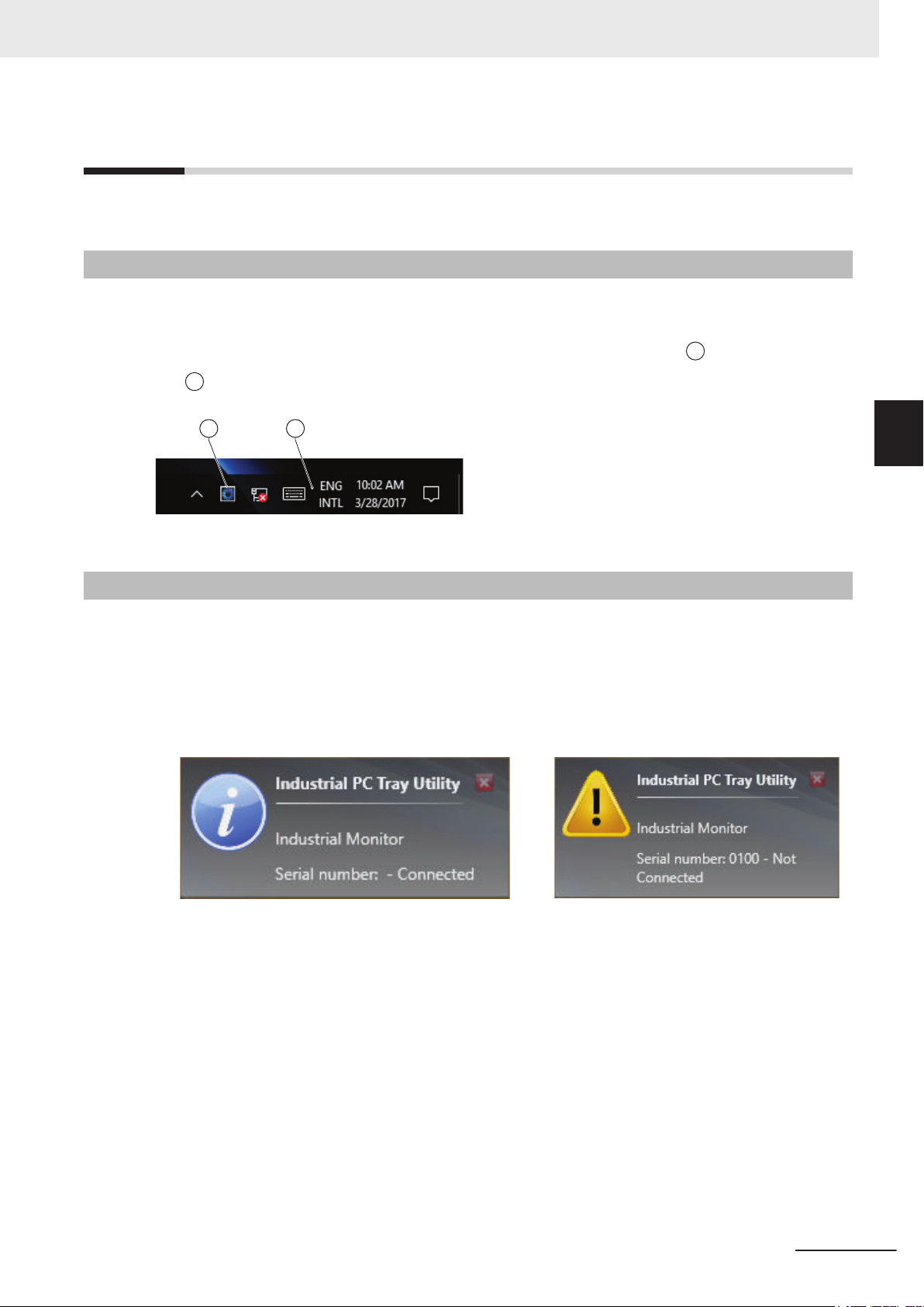
A B
3 Software
3-7
3-7-1
3-7-2
Industrial PC Tray Utility
This section provides an overview of the Industrial PC Tray Utility.
Industrial PC Tray Utility Overview
The Industrial PC Tray Utility is a software utility that provides information about the current state of
the Industrial PC, its related devices, and associated software.
When running, the Industrial PC Tray Utility is always present as a status icon A in the system tray
area B of Windows.
Windows 10
Features
3-7 Industrial PC Tray Utility
3
3-7-1 Industrial PC Tray Utility Overview
The Industrial PC Tray Utility provides the following features:
Display the overall state of all installed OMRON utilities in the icon in the system tray area.
•
•
Display a menu that can start all installed utilities and show the state of each installed utility.
• Display notification messages in popup windows that inform the user about the state of applications
or hardware. The Industrial PC Tray Utility displays the messages provided by installed OMRON
utilities. Refer to the OMRON utilities information for the messages that can be displayed.
NY-series Industrial PC Operating Systems and Software Utilities Manual (W616)
3-25
Page 60

F
B
C
E
F
D
A
A
B
C
E
3 Software
3-7-3
Menu
Select the Industrial PC Tray Utility icon
• The application displays the available utilities.
• Select an entry to launch the associated utility
• The icons of menu items in the Industrial PC Tray Utility menu will have a warning or error symbol
when applicable.
• The Industrial PC Support Utility
•
The Industrial Monitor Utility
• The Industrial Monitor Brightness Utility
• The application area can be configured to show and launch both OMRON and third party utilities.
is available in the menu when installed.
to display the menu.
, if applicable.
is available in the menu when installed.
is available in the menu when installed.
3-7-4
• The About entry
Refer to 3-7-4 About the Industrial PC Tray Utility on page 3-26
• The Exit entry
shows details of the Industrial PC Tray Utility.
for details.
closes the utility.
About the Industrial PC Tray Utility
The About window shows the version of the Industrial PC Tray Utility and copyright information.
3-26
NY-series Industrial PC Operating Systems and Software Utilities Manual (W616)
Page 61

3 Software
3-7-5
3-7-6
Status Indicators on Icons
The following table provides the indicator details of the Industrial PC Tray Utility.
Overlay type Icon Description
None No OMRON utility has issued warning or error notifications.
Warning sign At least one OMRON utility has issued a warning notification.
Error sign At least one OMRON utility has issued an error notification.
Compatibility
This software utility can be used on the IPC but also on any other PC with one of the following operat-
ing systems:
• Windows 10
Windows 7
•
3-7 Industrial PC Tray Utility
3
3-7-5 Status Indicators on Icons
3-7-7
Installation
The Industrial PC Tray Utility is pre-installed on the Industrial PC if it comes with a Windows operating
system installed.
The Industrial PC Tray Utility
trial Monitor Utility. Install the Industrial PC Support Utility or Industrial Monitor Utility to install the In-
dustrial PC Tray Utility.
is included in the installers of the Industrial PC Support Utility and Indus-
NY-series Industrial PC Operating Systems and Software Utilities Manual (W616)
3-27
Page 62

3 Software
3-7-8
Startup
By default the Industrial PC Tray Utility is configured to start automatically at Windows startup.
o manually start the Industrial PC T
T
ray Utility:
1 Locate the Industrial PC Tray Utility using the Windows Start menu or the Windows search
box.
2 Use the option Run as administrator to activate the Industrial PC T
Additional Information
The procedure to use Run as administrator is:
• For Windows 10 using the Start
Rightclick the Industrial PC Tray Utility, select More and then Run as administrator.
• For Windows 10 using Search:
Rightclick the Industrial PC Tray Utility in the search results and select Run as
administrator.
• For Windows 7 using the Start menu or Search:
Rightclick the Industrial PC Tray Utility and select Run as administrator.
The Industrial PC Tray Utility started.
menu:
ray Utility.
3-28
NY-series Industrial PC Operating Systems and Software Utilities Manual (W616)
Page 63

3 Software
3-8
3-8-1
3-8-2
Power Attendant Lite Utility
This section provides an overview of the Power Attendant Lite Utility (PAL).
Power Attendant Lite Utility Overview
The Power Attendant Lite Utility is a software utility that constantly monitors the status of the UPS that
is connected to the IPC.
When the Power Attendant Lite Utility discovers a power interruption it will send a signal to the IPC to
shut down.
Refer to the UPS Power Attendant Lite for Windows User's Manual for details.
Features
The Power Attendant Lite Utility provides the following features:
• Signal the IPC to shut down when a power interruption is detected.
• Configure the shutdown conditions when a power interruption is detected.
• Display the state of the connected UPS using the icon in the system tray area.
Icon Description
Normal operation
3-8 Power Attendant Lite Utility
3
3-8-1 Power Attendant Lite Utility Overview
3-8-3
Power Attendant Lite service stopped
UPS is supplying power from the internal battery
Communication error
Compatibility
This software utility can be used on the IPC but also on any other PC with one of the following operat-
ing systems:
Windows 10
•
•
Windows 7
NY-series Industrial PC Operating Systems and Software Utilities Manual (W616)
3-29
Page 64

3 Software
3-8-4
3-8-5
Installation
The Power Attendant Lite Utility is not pre-installed on a IPC.
The Power Attendant Lite Utility
lers). Download the installer from the OMRON website if required.
To install the Power Attendant Lite Utility
installer is included in the installers directory (D:\OMRON-NY\Instal-
:
1 Ensure the revision number of the UPS is correct.
Refer to the Hardware Manual for details.
2 Ensure the UPS is connected to the IPC with a USB cable.
3 Open the Power Attendant Lite Utility installer folder and activate the installer file setup.exe.
4 Follow the installer steps to complete the installation.
The Power Attendant Lite Utility is installed.
Configuration
Configure the Power Attendant Lite Utility before using the IPC with a UPS connected using USB.
To configure the
Power Attendant Lite Utility:
1 Activate the icon of the Power Attendant Lite Utility to start the software.
A UPS selection window will be displayed.
2 Select the connected UPS.
A Login window will be displayed.
3 Login with ID Admin and password omron.
op window with UPS status information will be displayed.
The T
3-30
4 Configure the parameters for your specific situation.
NY-series Industrial PC Operating Systems and Software Utilities Manual (W616)
Page 65

Refer to UPS Power Attendant Lite for Windows User's Manual for details.
3 Software
3-8 Power Attendant Lite Utility
5 Select
Port to display the parameter COM search to UPS detection
Detailed Setting / Other Settings / Communication Setting / UPS Communication
.
6 Set the parameter to Do not search for COM ports to prevent interference for the COM ports.
7 Select Submit to save the setting.
8 Select the close button in the right top corner to exit the
Power Attendant Lite Utility software.
9 Select the restart behavior of the IPC with the BIOS Boot Menu parameter Power Loss Con-
trol.
Set this parameter to Turn On to restart automatically after a power down from the Power At-
tendant Lite Utility.
10 Test the UPS shutdown behavior.
1) Start the IPC
2) Start applications
3) Create a power interruption
4) Monitor the shutdown sequence and confirm a correct shutdown
When the shutdown sequence is not correct change parameters in the Power Attendant
Lite Utility
The Power Attendant Lite Utility is configured.
The IPC will shut down properly in case of a power supply interruption and restart automatically when
the power is restored.
software and test the UPS shutdown behavior again.
3
3-8-5 Configuration
NY-series Industrial PC Operating Systems and Software Utilities Manual (W616)
3-31
Page 66

3 Software
3-9
3-9-1
Software for Developers
This section provides information on the software that is available for developers.
Overview IPC Developer Software for Windows
This section gives an overview of the software available for developers for all Industrial PC Platform
products with a Windows operating system.
Product Developer software
Industrial Monitor Industrial Monitor SDK
Industrial Monitor API
Industrial Box PC Industrial PC System SDK
Industrial PC System API
Industrial Panel PC Industrial Monitor SDK
Industrial Monitor API
Industrial PC System SDK
Industrial PC System API
Select and download the SDK software from the OMRON website.
3-32
NY-series Industrial PC Operating Systems and Software Utilities Manual (W616)
Page 67

3 Software
3-9-2
Industrial PC System API
This section describes some of the Industrial PC System API functions.
The Industrial PC System API allows programmers to create programs that can retrieve information or
set an indicator status of the product.
The API makes use of the included OMRON IPC System Service to manage the hardware.
Features
The Industrial PC System API can:
• Retrieve product information from the Industrial PC
•
Retrieve system flags
• Retrieve maintenance information
• Configure and program the Watchdog
• Set the status of the Run LED Indicator and the ERR LED Indicator
*1 Only for Industrial PCs with a Windows operating system.
Refer to 1-4 Product Configuration on page 1-5 for details.
*1
*1
3-9 Software for Developers
3
3-9-2 Industrial PC System API
Installation
The Industrial PC System API is part of the Industrial PC System SDK download.
The Industrial PC System API is pre-installed on the
Install the Industrial PC System SDK to use the Industrial PC System API on development PCs.
To use the Industrial PC System API the API needs to be referenced in your development project.
Use the Merge Module to include the Industrial PC System API in the installer for custom applications.
Industrial Panel PC
and the Industrial Box PC.
NY-series Industrial PC Operating Systems and Software Utilities Manual (W616)
3-33
Page 68

3 Software
3-9-3
Industrial Monitor API
This section describes some of the Industrial Monitor API functions.
The Industrial Monitor API
features and retrieve information from connected Industrial Monitors.
The main function of the Industrial Monitor API is to enable the brightness of the backlight and the
LEDs of the monitor to be increased or decreased according to the working environment.
The API makes use of the included OMRON Industrial Monitor Service to manage the hardware.
allows programmers to create applications that can control the hardware
Features
For all connected Industrial Monitors, the Industrial Monitor API can:
• Retrieve product information from the
• Retrieve product status information
• Set the brightness of the Status LED indicator
• Set the brightness of the backlight
• Set the brightness of the Logo LED
• Set the touch points of the monitor
• Store settings
• Restore to factory defaults
The API makes use of the included OMRON Industrial Monitor Service to manage all Industrial Moni-
tors connected via USB.
Industrial Monitor or Industrial Panel PC display
Installation
The Industrial Monitor API is part of the Industrial Monitor SDK download.
The Industrial Monitor API
Install the Industrial Monitor SDK to use the Industrial Monitor API on development PCs.
To use the Industrial Monitor API the API needs to be referenced in your development project.
Use the Merge Module to include the Industrial Monitor API in the installer for custom applications.
is pre-installed on the Industrial Panel PC and Industrial Box PC.
3-34
NY-series Industrial PC Operating Systems and Software Utilities Manual (W616)
Page 69

Specifications
This section provides specifications of the Industrial PC.
4
4
4-1 Software Specifications
4-1-1 Available Windows Operating Systems .......................................................... 4-2
4-1-2 Supported Languages .................................................................................... 4-3
................................................................................ 4-2
NY-series Industrial PC Operating Systems and Software Utilities Manual (W616)
4-1
Page 70

4 Specifications
4-1
4-1-1
Software Specifications
This section provides the Software Specifications of the Industrial PC.
Available Windows Operating Systems
The CPU type determines what Windows Operating Systems are available.
The CPU type is part of the model-ID.
Refer to 1-4-2 Product Configuration Panel PC on page 1-7 for model-ID details.
Windows
Model
• NY£2A
• NY£35
• NY£2C
• NY£1E
£25
• NY
• NY£1C
• NY£17
Operating
System
Windows 10 Windows 10
IoT Enterprise 2019 L
64 bit
Windows 10 Windows 10
IoT Enterprise 2016 LTSB 64 bit
Windows 7
• Windows Embedded
Standard 7 SP1 - 32 bit
• Windows Embedded
Standard 7 SP1 - 64 bit
Windows 10 Windows 10
IoT Enterprise 2016 LTSB 64 bit
Edition Remark
The Long-term Servicing Channel of Windows
TSC -
is primarily for specialized devices.
The LTSC of Windows excludes most of the
bundled applications, including Microsoft
Edge. Note: In the software the name L
might still be displayed.
The Long-term Service Branch of Windows is
primarily for specialized devices.
The LTSB of Windows excludes most of the
bundled applications, including Microsoft
Edge.
An Internet Browser, Firewall and Anti-virus
software are not pre-installed.
The Long-term Service Branch of Windows is
primarily for specialized devices.
The LTSB of Windows excludes most of the
bundled applications, including Microsoft
Edge.
TSB
4-2
NY-series Industrial PC Operating Systems and Software Utilities Manual (W616)
Page 71

4 Specifications
4-1-2
Supported Languages
Languages default supported by the operating system are:
Language Windows 10 Windows 7
EN
CN Simplified (zh-cn)
CN Traditional (zh-tw)
DE
ES
FR
IT
JA
KO
Additional Information
Refer to the Microsoft support information for details on available language packs.
4-1 Software Specifications
4
4-1-2 Supported Languages
NY-series Industrial PC Operating Systems and Software Utilities Manual (W616)
4-3
Page 72

4 Specifications
4-4
NY-series Industrial PC Operating Systems and Software Utilities Manual (W616)
Page 73

Installation
This section provides all installation details for the Industrial PC.
5
5-1 Install Software
5-1-1 Internet Browser ............................................................................................. 5-2
5-1-2 Firewall ........................................................................................................... 5-3
5-1-3 Anti-virus Software.......................................................................................... 5-3
5-1-4 Drivers and Custom Software......................................................................... 5-4
5-1-5 Activate Windows ........................................................................................... 5-4
5-1-6 Customize Windows ....................................................................................... 5-4
5-2 Install Support Software................................................................................ 5-5
5-2-1 Overview IPC Support Software for Installation.............................................. 5-5
5-3 Create Backup and Repair Media .................................................................5-6
............................................................................................... 5-2
5
NY-series Industrial PC Operating Systems and Software Utilities Manual (W616)
5-1
Page 74

5 Installation
5-1
5-1-1
Install Software
This section describes how to install the software for the Industrial PC.
Internet Browser
Depending on the operating system an Internet Browser is preinstalled.
• For Windows 10 the standard Internet Browser is installed.
• For Windows 7 an executable file for browser installation is provided in the user data partition of the
drive. For Windows 7 use the procedure below to perform the browser installation.
Additional Information
• Check the IT policy of your company for available software and for details on the software
environment the Industrial PC will operate in.
• Install all updates and ensure the browser stays up-to-date.
To install the available Internet Browser in a Windows 7 operating system:
1 Use Windows Explorer to examine the contents of the user data partition mapped as drive let-
ter D:.
2 Open the Installer folder (D:\OMRON-NY\Installers) and locate the Internet Explorer installer
files.
3 Select the installer suitable for your system (32/64 bits) and language (English/Japanese).
4 Ensure there is a connection to the Internet.
5 Launch the installer to begin the installation process.
6 Follow the installer steps to complete the browser installation.
7 Download and install the latest updates via Windows Update.
The Internet Browser is installed in Windows 7.
5-2
NY-series Industrial PC Operating Systems and Software Utilities Manual (W616)
Page 75

5 Installation
5-1-2
5-1-3
Firewall
An industrial network should be separated from an office network.
Depending on the operating system a Firewall is preinstalled.
For Windows 10 the standard firewall software is installed and enabled.
•
•
For Windows 7 the Firewall software is not installed.
Precautions for Safe Use
• Separate the machine network segment from the office network to avoid communication failures.
• Install all updates and ensure the firewall stays up-to-date.
Additional Information
Check the IT policy of your company for available software and for details on the software environment the Industrial PC
will operate in.
Anti-virus Software
The Windows operating system is vulnerable for viruses. Anti-virus software should be installed on the
Windows operating system.
Depending on the operating system Anti-virus software is preinstalled.
For Windows 10 the standard Anti-virus software is installed and enabled.
•
•
For Windows 7 Anti-virus software is not installed.
5-1 Install Software
5
5-1-2 Firewall
Additional Information
Check the IT policy of your company for available software and for details on the software environment the Industrial PC
Precautions for Safe Use
• Make sure that your operating system environment is protected against malicious software
and viruses.
• Install all updates and ensure virus definitions stay up-to-date.
will operate in.
NY-series Industrial PC Operating Systems and Software Utilities Manual (W616)
5-3
Page 76

5 Installation
5-1-4
5-1-5
Drivers and Custom Software
Use the following procedure to install drivers and custom software on your Industrial PC.
For an Industrial PC without Operating System
•
• For an Industrial PC with a Windows operating system the drivers for most OMRON devices and
common third party devices are already available on the product. They will be installed automatically
after the initial Windows configuration or upon connection of a device to the
ers from
the OMRON website if reinstallation is required.
download the drivers from
the OMRON website.
IPC. Download the driv-
1 Install drivers that are required for the application.
2 Install third-party software that is required for the application.
Follow the installation instructions as supplied with the driver or software.
Precautions for Safe Use
Before operating the system, please make sure the appropriate software is installed and configured. Doing so may prevent unexpected operation.
Activate Windows
5-1-6
To activate Windows an internet connection is required.
If an internet connection is not available during the installation process then the Windows license will
only be active after an internet connection has been established.
Activation is not required, a non-activated version of Windows is fully functional.
Refer to the Hardware Manual for the location of the Windows product key.
Customize Windows
Windows provides customization tools.
Using these tools is only allowed for experienced software engineers.
Additional Information
• For Windows 10:
• Refer to
• Refer to A-1-4 Trusted Platform Module on page A-6 for TPM details.
• For Windows 7:
• Refer to for EWF details.
• Refer to for FBWF details.
• Refer to A-1-4 Trusted Platform Module on page A-6 for TPM details.
A-1-3 Unified Write Filter on page A-5 for UWF details.
5-4
NY-series Industrial PC Operating Systems and Software Utilities Manual (W616)
Page 77

5 Installation
5-2
5-2-1
Install Support Software
This section describes how to install the support software for the Industrial PC.
Overview IPC Support Software for Installation
This section gives an overview of the IPC support software available for your Industrial PC.
Software Utilities
The applicable software utilities are already installed on your Industrial PC when a storage device is
available. Refer to the details in the table to find installation details.
The software utilities can be downloaded from the OMRON website.
Additional Information
An internet connection is required to install support software.
Product Details
Industrial PC Support Utility Refer to 3-3-6 Installation
Industrial PC Tray Utility Refer to 3-7-7 Installation on page
The Industrial PC Tray Utility includes Microsoft .NET Framework 4.6.
Microsoft .NET Framework 4.6 Comes with the Industrial PC Tray Utility.
Rescue Disk Creator Refer to 3-6-3 Installation on page
Industrial Monitor Utility Refer to 3-4-3 Installation on page
Industrial Monitor Brightness Utility Refer to 3-5-3 Installation on page
on page
3-9 for details.
3-27 for details.
3-20 for details.
3-15 for details.
3-18 for details.
5-2 Install Support Software
5
5-2-1 Overview IPC Support Software for Installation
Software for developers
Product Details
Industrial PC System API Refer to Installation on page 3-33
Industrial Monitor API Refer to Installation on page 3-34
Congatec CGOS API No details available. The functionality is available in the Industrial PC
System API.
for details.
for details.
NY-series Industrial PC Operating Systems and Software Utilities Manual (W616)
5-5
Page 78

5 Installation
5-3
Create Backup and Repair Media
Create the storage media to recover, restore or repair the operating system and other important files.
There are several methods available, each with their own advantages and limitations.
Additional Information
Note that you can select more than one methods to create your recover, restore or repair media.
1 Refer to Overview of Recover, Restore and Repair Methods on page
best procedure for your situation.
2 Perform the procedures to create the desired storage media.
7-3 and choose the
5-6
NY-series Industrial PC Operating Systems and Software Utilities Manual (W616)
Page 79

Operating Procedures
This section provides the operating procedures for the Industrial PC.
6
6-1 React to Product Messages
6-2 React to Windows Messages ........................................................................ 6-3
.......................................................................... 6-2
6
NY-series Industrial PC Operating Systems and Software Utilities Manual (W616)
6-1
Page 80

A B
6 Operating Procedures
6-1
React to Product Messages
The Industrial PC uses the Industrial PC Tray Utility icon A in the system tray area B of Windows to
present Warnings and Errors.
Check the Industrial PC Tray Utility icon for a Warning or Error symbol.
A Warning or Error symbol displayed on the
sage.
To react to a product message:
1 Select the Industrial PC Tray Utility icon.
A pop-up window will appear.
2 Read the message available in the pop-up.
Industrial PC Tray Utility icon indicates a product mes-
3 Refer to
Perform the actions presented for the message until the Warning or Error is resolved.
The product messages for the Industrial PC are resolved.
7-2-1 Warning and Error Messages on page
7-19 for all details on the message.
6-2
NY-series Industrial PC Operating Systems and Software Utilities Manual (W616)
Page 81

AB
A B
6 Operating Procedures
6-2
React to Windows Messages
Windows uses the Windows Action Center icon A in the system tray area B of Windows to present
Warnings and Errors.
Windows 10 Windows 7
Check the Windows Action Center icon for a Warning or Error symbol.
A W
arning or Error symbol displayed on the
sage.
To react to a Windows message:
1 Open the Windows Action Center.
• For Windows 10: Click the Windows Action Center
• For Windows 7: Rightclick the Windows Action Center icon and select Open Action Center
from the pop-up window.
A pop-up window will appear.
Windows Action Center icon indicates a Windows mes-
icon.
6-2 React to Windows Messages
6
Windows 10 Windows 7
2 Read the message available in the window.
3 Perform the actions until each Warning or Error is resolved.
The Windows messages for the Industrial PC are resolved.
NY-series Industrial PC Operating Systems and Software Utilities Manual (W616)
6-3
Page 82

6 Operating Procedures
6-4
NY-series Industrial PC Operating Systems and Software Utilities Manual (W616)
Page 83

Maintenance
This section provides an overview of the software maintenance tasks for the Industrial
PC.
The hardware maintenance tasks are available in the hardware manuals.
For NYB£ and NYP£ refer to the following manuals:
• NY-series Industrial Box PC Hardware User
• NY-series Industrial Panel PC Hardware User’s Manual (Cat. No. W555)
7-1 Preventive Maintenance ................................................................................7-2
7-1-1 Preventive Maintenance Schedule ................................................................. 7-2
7-1-2 Keep Software Updated.................................................................................. 7-2
7-1-3 Create Backup and Repair Data..................................................................... 7-3
7-1-4 Check the Storage Device Status................................................................. 7-15
7-1-5 Check the Backup and Repair Media ........................................................... 7-17
7-2 Corrective Maintenance............................................................................... 7-19
7-2-1 Warning and Error Messages ....................................................................... 7-19
7-2-2 Restore and Repair Data .............................................................................. 7-20
7-2-3 Allocate a Drive in Windows ......................................................................... 7-28
7-2-4 Windows Event Viewer ................................................................................. 7-29
7-2-5 Windows Low on Memory............................................................................. 7-31
7-2-6 Windows Blue Screens................................................................................. 7-32
7-2-7 Correct Display Functionality when Nothing is Displayed............................. 7-32
7-2-8 Correct Touchscreen Functionality ............................................................... 7-33
7
’s Manual (Cat. No. W553)
7
NY-series Industrial PC Operating Systems and Software Utilities Manual (W616)
7-1
Page 84

7 Maintenance
7-1
7-1-1
Preventive Maintenance
Preventive Maintenance covers all actions that prevent downtime.
Preventive Maintenance Schedule
Prevent unscheduled downtime with the following preventive maintenance schedule.
Daily Reference
Check Industrial PC status Refer to 7-2-1 W
ble messages.
Weekly Reference
Ensure you have the latest software updates
When changing applications or
configurations
Create a backup of the Industrial
PC
Refer to 7-1-2 Keep Software Updated on page 7-2 for update details.
Refer to 7-1-3 Create Backup and Repair Data on page 7-3 for backup
details.
arning and Error Messages
Reference
on page 7-19 for all availa-
7-1-2
Periodically but at least every 6
months
Check the status of storage devices.
Check the backup and repair media.
Refer to 7-1-4 Check the Storage Device Status on page 7-15 for details.
Refer to
tails.
7-1-5 Check the Backup and Repair Media on page 7-17 for de-
Reference
Keep Software Updated
Always keep software at the latest released version to ensure stable operation.
This is specifically important for:
Anti-virus software
•
•
Firewall software
• Internet browser
• Windows security patches
• OMRON software
Precautions for Correct Use
After an OS update or a peripheral device driver update for the product is executed, the product
behavior might be different. Confirm that operation is correct before you start actual operation.
7-2
Additional Information
• Refer to for Browser details.
• Refer to
• Refer to 5-1-3 Anti-virus Software on page 5-3 for Anti-virus details.
5-1-2 Firewall on page 5-3 for Firewall details.
NY-series Industrial PC Operating Systems and Software Utilities Manual (W616)
Page 85

7 Maintenance
7-1-3
Create Backup and Repair Data
Ensure the operating system, software and data can always be restored when required.
There are dif
Refer to
ferent software tools to create a backup and repair data.
Overview of Recover, Restore and Repair Methods on page 7-3 for an overview of the pos-
sibilities and their goals and requirements.
Precautions for Correct Use
Create backups according to the preventive maintenance schedule to prevent data loss and
system integrity issues.
Refer to 7-1-1 Preventive Maintenance Schedule on page 7-2 for intervals.
Select the Backup and Repair procedure or procedures that are most suitable for your situation.
Overview of Recover, Restore and Repair Methods
Depending on the goal and depending on the available backup and repair data an applicable backup
and recover, restore or repair action can be selected.
An overview of the dif
ferent methods to restore and repair Windows and custom files:
7-1 Preventive Maintenance
Tool Goal
Omron
Rescue Disk
Windows
System Repair
disk
Restore the
• Windows par-
tition
• Boot partition
• MBR = GPT
Restore Windows 7 to a previous state
Preparation in
advance
Create a Rescue Disk
Create a Windows System
Repair disk
Restore details Refer to
• A partial recovery or re-
covery of user data is
not possible
• The IPC recovers to
the state of the previously created Rescue
Disk image
• Uses a USB storage
device
• A partial recovery or re-
covery of user data is
not possible
• Windows recovers to
the state of the previously created Repair
disk image
• Uses a DVD
Prepare: Create a New
Rescue Disk with the
Rescue Disk Creator on
page 7-6
Create
Backup with the Rescue
Disk on page 7-5
Check: Check the Backup
Information on the Rescue Disk on page 7-17
Restore: Restore a Sys-
tem Backup with the Rescue Disk on page 7-21
Create: Create a Windows 7 System Repair
Disk
Check: Check the System
Repair Disk (Windows)
Restore: Repair Windows
7 with the System Repair
Disk
• The IPC can boot with
this disk
: Create a System
7
7-1-3 Create Backup and Repair Data
NY-series Industrial PC Operating Systems and Software Utilities Manual (W616)
7-3
Page 86

7 Maintenance
Tool Goal
Windows Recovery disk
Windows
Backup and Restore
Restore Windows 10 to a
previous state
Restore a user's
selection of folders
Preparation in
advance
Create a Windows Recovery
disk
Create a Windows Backup
Restore details Refer to
• A partial recovery or re-
covery of user data is
not possible
• Windows recovers to
the state of the previously created Recovery
image
Create: Create a Win-
dows 10 Recovery Drive
on page 7-
Restore: Recover Win-
dows 10 with the Recovery Drive on page 7-27
• Uses a USB storage
device
• The IPC can boot with
this USB
• The data is restored to
the state of the previously created backup
• Recovery of specific
folders is possible.
Backups can be created automatically at predefined intervals
• No recovery of the Win-
dows operating system
Create: Create a Custom
Backup with Windows
Backup on page 7-12
Check: Check the Cus-
tom Backup Storage Device (W
7-17
Restore: Restore a Cus-
tom Backup with Windows
on page 7-23
• Uses any type of stor-
age device
10
indows) on page
Additional Information
Contact your OMRON representative when the IPC needs to be restored and you do not have
any restore or recover possibility.
7-4
NY-series Industrial PC Operating Systems and Software Utilities Manual (W616)
Page 87

7 Maintenance
Create a System Backup with the Rescue Disk
A Rescue Disk is a disk with the Rescue Disk Utility; this is the software that performs the system
backup and system restore procedures of the IPC.
A system backup contains the Windows partition, the boot partition and the MBR.
A system backup can not include the User Data partition.
Precautions for Correct Use
The backup data of the Rescue Disk can be used to recover the data of the IPC that created
that backup. It can also restore data to another IPC if the product configuration is identical to
the IPC that created the backup.
Additional Information
To create a system backup a Rescue Disk should be available.
• Refer to
Disk creation.
• Refer to Messages Using the Rescue Disk on page 3-23 for Rescue Disk error messages.
Create a New Rescue Disk with the Rescue Disk Creator on page 7-6 for Rescue
7-1 Preventive Maintenance
To create a system backup:
1 Ensure the IPC is powered OFF.
2 Ensure a keyboard is connected to the IPC.
3 Connect the Rescue Disk to a USB connector of the IPC.
4 Power ON the IPC while pressing the F11
The option to select your boot device will appear.
Your Rescue Disk will be displayed in this boot menu with the manufacturer data of your USB
device.
If your boot device is not visible in this list:
key twice per second.
7
7-1-3 Create Backup and Repair Data
1) Disconnect the USB connector of the Rescue Disk.
2) Re-insert the USB connector of the Rescue Disk.
3) Select Ctrl, Alt and Delete to reboot the IPC.
4) Press the F11
The option to select your boot device will appear with your boot device in the list.
NY-series Industrial PC Operating Systems and Software Utilities Manual (W616)
key twice per second.
7-5
Page 88

Welcome to the Rescue Disk Utility . , what would you like to do?
Create Backup
Restore Backup
Backup information
Storage device information
Exit
7 Maintenance
5 Use the arrow keys to select the Rescue Disk and then select Enter.
6 Select Create Backup.
The menu window opens.
The mentioned number can be different from the number displayed on your screen.
The backup confirmation window opens.
or
Windows 7 Windows 10
7 Select Continue to start the system backup process.
Wait until the message
Backup finished appears.
8 The message Would you like to enter an optional comment for the created backup? gives
the option to add an extra remark to the created backup.
Select
Select Yes to add the optional comment. Add the comment and press [Enter] to finalize the
backup creation.
No to exit without an optional comment.
9 Select OK to return to the main menu.
10 Select Exit to close the Rescue Disk Utility.
The IPC
will power OFF.
11 Remove the Rescue Disk and store it in a safe place.
A system backup is created on the Rescue Disk.
Precautions for Correct Use
Create backups according to the preventive maintenance schedule to prevent data loss and
system integrity issues.
Refer to 7-1-1 Preventive Maintenance Schedule on page 7-2 for intervals.
Additional Information
Refer to Restore a System Backup with the Rescue Disk on page 7-21 for system restore details.
Create a New Rescue Disk with the Rescue Disk Creator
A Rescue Disk is a disk with the Rescue Disk Utility that enables users to create a system backup
and to do a system restore.
A system backup contains the Windows partition, the boot partition and the MBR.
7-6
NY-series Industrial PC Operating Systems and Software Utilities Manual (W616)
Page 89

7 Maintenance
Prepare:
• The Rescue Disk Creator
Refer to
Refer to Messages Creating the Rescue Disk on page 3-22 for message details.
• A USB storage device that has sufficient capacity to backup the content of the IPC. The capacity
should be at least the Windows partition size + 16 GB. The recommended minimum read/write
speed is 190 MB/s.
Note that all content on this USB storage device will be erased during the Rescue Disk creation.
Use the following procedure to create a new Rescue Disk:
3-6-3 Installation on page 3-20 for installation details.
1 Connect a USB storage device that has sufficient capacity to backup the content of the IPC.
2 Select the Windows Start Button.
3 In the search field, input Rescue.
4 Right-click Rescue Disk Creator and then select Run as administrator.
The Rescue Disk Creator Utility window opens.
7-1 Preventive Maintenance
5 Select the connected USB storage device at Target disk:
Refer to 3-6-5 Messages on page 3-21 for message details if required.
The button Create Rescue Disk will be enabled as soon as a USB storage device is detected
and accepted.
.
6 Select the Create Rescue Disk button to start the creation process.
ait until the progress bar shows the Rescue Disk creation finished.
W
Refer to 3-6-5 Messages on page 3-21 for message details if required.
7 Select Close to close the Rescue Disk Creator.
The Rescue Disk is
Next step is to create a system backup with this Rescue Disk.
Additional Information
• Refer to Create a System Backup with the Rescue Disk on page
tails.
Refer to Restore a System Backup with the Rescue Disk on page 7-21 for system restore
•
details.
available but it is still empty, there is no system backup on the Rescue Disk.
7-5 for system backup de-
7
7-1-3 Create Backup and Repair Data
NY-series Industrial PC Operating Systems and Software Utilities Manual (W616)
7-7
Page 90

7 Maintenance
Create a Windows 7 System Repair Disk
A Windows System Repair Disk can repair Windows if a serious error occurs.
Additional Information
To create a Windows System Repair Disk, a separate Windows PC with a DVD writer is required that has the same Windows edition and System type as the Industrial PC. The Windows
System Repair Disk can not be created with the
Prepare:
• A PC with a DVD writer that has the same Windows edition and System type as your IPC.
•
An example of the Windows edition is "Windows 7" with "Service Pack 1".
• An example of the System type is "64-bit Operating System".
• An empty DVD
Use the Windows Backup and Restore mechanisms on the PC with a DVD writer to create a system
repair disk.
Industrial PC.
To create a Windows System Repair Disk:
1 Start the PC that has a DVD writer and login.
2 Select the Windows Start Button.
3 In the search field, input Backup.
4 Select Backup and Restore.
The Backup and Restore window opens.
5 Select Create a system repair disk.
The Create a system repair disk window opens.
7-8
NY-series Industrial PC Operating Systems and Software Utilities Manual (W616)
Page 91

7 Maintenance
6 Select the applicable drive letter of the DVD writer and then select Create disk.
7 Wait until the disk is created and the remove it and store it in a safe place.
Additional Information
Refer to http://windows.microsoft.com/ for Backup and Restore details.
7-1 Preventive Maintenance
7
7-1-3 Create Backup and Repair Data
NY-series Industrial PC Operating Systems and Software Utilities Manual (W616)
7-9
Page 92

E:\MyUSB
7 Maintenance
Create a Windows 10 Recovery Drive
A Windows recovery drive can repair Windows if a serious error occurs.
Prepare:
• A USB storage device that has suf
should be at least the Windows partition size + 16 GB. The recommended minimum read/write
speed is 190 MB/s.
Note that all content on this USB storage device will be erased.
Use the following procedure to create a Windows recovery drive:
1 Insert the USB storage device in a USB 3.0 connector.
2 Select the Windows Start Button.
3 In the search field, input recovery drive.
ficient capacity to backup the content of the IPC. The capacity
4 Select Create a recovery drive.
The recovery drive window opens.
5 Check the checkbox Back up system files to the recovery drive and then select Next
The drive selection window opens.
.
7-10
6 Select the applicable drive letter and then select Next.
The Create window will appear
.
NY-series Industrial PC Operating Systems and Software Utilities Manual (W616)
Page 93

7 Maintenance
7 Read the warning and if your personal files are safe then select Create.
8 Wait until the progress bar is finished and the message The recovery drive is ready appears.
9 Remove the USB storage device and store it in a safe place.
The Windows recovery drive is ready.
Additional Information
Refer to http://windows.microsoft.com/ for recovery drive details.
7-1 Preventive Maintenance
7
7-1-3 Create Backup and Repair Data
NY-series Industrial PC Operating Systems and Software Utilities Manual (W616)
7-11
Page 94

7 Maintenance
Create a Custom Backup with Windows Backup
Use the following procedure to create a custom backup of the Industrial PC with the Windows Backup
and Restore mechanism.
To manually or automatically create a customized backup:
1 Select the Windows Start
Button.
2 In search field, input Backup.
3 Select Backup and Restore.
The Backup and Restore window opens.
4 Select Set up backup.
The Set up backup window opens.
7-12
5 Select the backup destination.
A network location can be added with Save on a network.
Additional Information
Preferred locations for an automatic backup are:
• A network drive
•
The local drive in drive bay B, when installed.
NY-series Industrial PC Operating Systems and Software Utilities Manual (W616)
Page 95

6 Select Next.
The following window will appear:
7 Maintenance
7 Select Let me choose and then select Next.
The following window will appear:
8 Select all directories you want to include in the backup.
7-1 Preventive Maintenance
7
7-1-3 Create Backup and Repair Data
9 Select Next.
NY-series Industrial PC Operating Systems and Software Utilities Manual (W616)
7-13
Page 96

7 Maintenance
10 Select Configure schedule or Change schedule and change the backup schedule.
11 Select OK.
12 Select Save settings and run backup to create the first backup.
Precautions for Correct Use
Create backups according to the preventive maintenance schedule to prevent data loss and
system integrity issues.
Refer to 7-1-1 Preventive Maintenance Schedule on page 7-2 for intervals.
Ensure:
• The interval is short enough to minimize data loss when a restore is required
The Industrial PC is powered ON during the backup periods
•
• The time the backup is scheduled does not interfere with normal operation
or uncheck Run backup on a schedule if an automatic backup is not possible.
Additional Information
• Check your backup to ensure it contains all data required for a restore.
• Refer to http://windows.microsoft.com/ for Backup and Restore details.
Refer to Restore a Custom Backup with Windows on page 7-23 for the Restore Procedure.
•
7-14
NY-series Industrial PC Operating Systems and Software Utilities Manual (W616)
Page 97

7 Maintenance
7-1-4
Check the Storage Device Status
The Rescue Disk is a disk with the Rescue Disk Utility; this software can display the status of all Om-
ron-approved storage devices.
Version Information
The device status information is only available for products with an Atom CPU. The Rescue
Disk Utility should be version 0001.0000 or higher.
Refer to
Additional Information
To check the status of a storage device a Rescue Disk should be available.
• Refer to
• Refer to Messages Using the Rescue Disk on page 3-23 for Rescue Disk error messages.
To check the status of a storage device:
1-4 Product Configuration on page 1-5 for details.
Create a New Rescue Disk with the Rescue Disk Creator on page 7-6 for Rescue
Disk creation.
1 Ensure the IPC is powered OFF.
7-1 Preventive Maintenance
2 Ensure a keyboard is connected to the IPC.
3 Connect the Rescue Disk to a USB connector of the IPC.
4 Power ON the IPC while pressing the F11
The option to select your boot device will appear.
Your Rescue Disk will be displayed in this boot menu with the manufacturer data of your USB
device.
If your boot device is not visible in this list:
1) Disconnect the Rescue Disk from the USB connector of the IPC.
2) Re-connect the Rescue Disk to the IPC.
key twice per second.
7
7-1-4 Check the Storage Device Status
3) Select Ctrl, Alt and Delete to reboot the IPC.
4) Press the F11
The option to select your boot device will appear with your boot device in the list.
NY-series Industrial PC Operating Systems and Software Utilities Manual (W616)
key twice per second.
7-15
Page 98

Welcome to the Rescue Disk Utility . , what would you like to do?
Create Backup
Restore Backup
Backup information
Storage device information
Exit
Storage device information:
IPC model: NY512-1300-1XX214K1D
=== 1 ===
Storage device name: sda
Storage device type: 32 GB SATA F
lash
Storage device state: operational
Storage device firmware: L17606
OK
7 Maintenance
5 Use the arrow keys to select the Rescue Disk and then select Enter.
6 Select Storage device information.
The Rescue Disk window opens.
Where £.£ displays the version of the Rescue Disk.
The storage devices information window opens.
7 Check the storage device state and take action when required.
Storage device
state
unknown Storage device state could not be deter-
mined
operational Storage device state is in operational
mode and functioning normally
pre-maintenance Storage device state is in pre-mainte-
nance mode and functioning normally
maintenance Storage device state is in maintenance
mode and functioning normally
critical Storage device state is in critical mode
and normal operation cannot be guaranteed
Description Action
Contact your OMRON representative
for further support
Storage device functioning normally, no
action required
Storage device replacement should be
scheduled
Storage device replacement is required
Storage device should be replaced immediately as normal operation cannot
be guaranteed
8 Select OK to return to the main menu.
9 Select Exit to close the Rescue Disk Utility.
10 Remove the Rescue Disk and store it in a safe place.
The storage device status is known.
7-16
NY-series Industrial PC Operating Systems and Software Utilities Manual (W616)
Page 99

Lorem ipsum dolor sit amet,
consecBack
uBackup created on $(cat
${DATE_OF_BACKUP_FILE}).
Backup created on Fri Dec 1 12:34:56
Model name : NY512-1300
Serial number : 0123
Lot number : 01234N
Content : MBR, Boot,
Windows and Machine Control partitions
Unit version : V1.16.00
OSB version : 0000.0016
Comment by user : demo for m
anual - your content will be different
Current System:
Model name : NY
Serial number : 0123
Lot number : 01234N
Unit version : V1.16.00
OSB version : 0000.0016
OK
7 Maintenance
7-1-5
Check the Backup and Repair Media
Use the following procedure to check the backup or repair media.
Check the Backup Information on the Rescue Disk
Use the following procedure to check the rescue disk for the system backup.
1 Use the rescue disk to boot the IPC.
Refer to Restore a System Backup with the Rescue Disk on page 7-21
Follow the first few steps of the procedure until following screen appears:
2 Select Backup Information and then Enter.
Following screen will appear:
for details.
7-1 Preventive Maintenance
3 Check the content. If there is no content then there is no usable backup on this Rescue Disk.
4 Select Exit.
The rescue disk information is checked.
Check the Custom Backup Storage Device (Windows)
Use the following procedure to check the custom backup storage device.
1 Insert the storage device with the backup in the Industrial PC that created the backup.
2 Follow the first few steps of the restore procedure to display the 'Restore files' screen.
Refer to Restore a Custom Backup with W
3 Browse the storage device and ensure at least one backup is displayed.
NY-series Industrial PC Operating Systems and Software Utilities Manual (W616)
4 Select Cancel to cancel the restore procedure.
The storage device with the custom backup is approved.
indows on page 7-23
7
7-1-5 Check the Backup and Repair Media
for details.
7-17
Page 100

7 Maintenance
Check the System Repair Disk (Windows)
Use the following procedure to check the system repair disk to repair Windows.
1 Follow the first few steps of the repair procedure to display the recovery software screen to se-
2 Exit the recovery software.
The backup medium for the system repair disk is approved.
lect your keyboard language.
Refer to Repair Windows 7 with the System Repair Disk on page 7-
26 for details.
7-18
NY-series Industrial PC Operating Systems and Software Utilities Manual (W616)
 Loading...