

Page 1
Industrial PC Platform
NY-series
IPC Machine Controller
Industrial Panel PC / Industrial Box PC
Motion Control
User’s Manual
NY532-1500
NY532-1400
NY532-1300
NY532-5400
NY512-1500
NY512-1400
NY512-1300
Industrial Panel PC
Industrial Box PC
W559-E1-03
Page 2

NOTE
All rights reserved. No part of this publication may be reproduced, stored in a retrieval system, or transmitted, in
any form, or by any means, mechanical, electronic, photocopying, recording, or otherwise, without the prior
written permission of OMRON.
No patent liability is assumed with respect to the use of the information contained herein. Moreover, because
OMRON is constantly striving to improve its high-quality products, the information contained in this manual is
subject to change without notice. Every precaution has been taken in the preparation of this manual. Nevertheless, OMRON assumes no responsibility for errors or omissions. Neither is any liability assumed for damages
resulting from the use of the information contained in this publication.
Trademarks
• Sysmac and SYSMAC are trademarks or registered trademarks of OMRON Corporation in Japan and other
countries for OMRON factory automation products.
• Microsoft, Windows, Excel, and Visual Basic are either registered trademarks or trademarks of Microsoft Corporation in the United States and other countries.
• EtherCAT® is registered trademark and patented technology, licensed by Beckhoff Automation GmbH, Germany.
• ODVA, CIP, CompoNet, DeviceNet, and EtherNet/IP are trademarks of ODVA.
• The SD and SDHC logos are trademarks of SD-3C, LLC.
• Intel and Intel Core are trademarks of Intel Corporation in the U.S. and / or other countries.
Other company names and product names in this document are the trademarks or registered trademarks of their
respective companies.
Copyrights
Microsoft product screen shots reprinted with permission from Microsoft Corporation.
Page 3

Introduction
Thank you for purchasing an NY-series IPC Machine Controller Industrial Panel PC / Industrial Box PC.
This manual provides a collective term of Industrial Panel PC and Industrial Box PC which are applicable products as the NY-series Industrial PC. This manual also provides the range of devices that are
directly controlled by the Controller functions embedded the Real-Time OS in the NY-series Industrial
PC as the Controller.
This manual contains information that is necessary to use the Motion Control Function Module of an
NY-series Controller. Please read this manual and make sure you understand the functionality and performance of the NY-series Controller before you attempt to use it in a control system.
Keep this manual in a safe place where it will be available for reference during operation.
Intended Audience
This manual is intended for the following personnel, who must also have knowledge of electrical systems (an electrical engineer or the equivalent).
• Personnel in charge of introducing FA systems.
• Personnel in charge of designing FA systems.
• Personnel in charge of installing and maintaining FA systems.
• Personnel in charge of managing FA systems and facilities.
Introduction
For programming, this manual is intended for personnel who understand the programming language
specifications in international standard IEC 61131-3 or Japanese standard JIS B 3503.
Applicable Products
This manual covers the following products.
NY-series IPC Machine Controller Industrial Panel PC
• NY532-15
• NY532-14
• NY532-13
• NY532-5400
NY-series IPC Machine Controller Industrial Box PC
• NY512-15
• NY512-14
• NY512-13
Part of the specifications and restrictions for the Industrial PC are given in other manuals. Refer to Relevant Manuals on page 2 and Related Manuals on page 22.
NY-series Industrial Panel PC / Industrial Box PC Motion Control User’s Manual (W559)
1
Page 4
Relevant Manuals
Relevant Manuals
The following provides the relevant manuals for NY-series Controller.
Read all of the manuals that are relevant to your system configuration and application before you use
NY-series Controller.
Most operations are performed from the Sysmac Studio Automation Software. Refer to the Sysmac Stu-
dio Version 1 Operation Manual (Cat. No. W504) for information on the Sysmac Studio.
NY-series IPC Machine Controller
Industrial Panel PC
Hardware User’s Manual
Purpose of use
Basic information
NY-series IPC Machine Controller
Industrial Box PC
Hardware User’s Manual
Industrial Panel PC / Industrial Box PC
Setup User's Manual
Manual
NY-series IPC Machine Controller
NY-series IPC Machine Controller
Industrial Panel PC / Industrial Box PC
Software User’s Manual
Instructions Reference Manual
NY-series
Motion Control User's Manual
Industrial Panel PC / Industrial Box PC
NY-series IPC Machine Controller
NY-series Motion Control
Instructions Reference Manual
NY-series IPC Machine Controller
Industrial Panel PC / Industrial Box PC
Built-in EtherCAT Port User’s Manual
Built-in EtherNet/IP Port User's Manual
Industrial Panel PC / Industrial Box PC
NY-series IPC Machine Controller
NJ/Y-series NC Integrated Controller
User's Manual
Troubleshooting Manual
NY-series
Introduction to NY-series Panel PCs
Introduction to NY-series Box PCs
Setting devices and hardware
Using motion control
Using EtherCAT
Using EtherNet/IP
Making setup
Making initial settings
Preparing to use Controllers
Software settings
Using motion control
Using EtherCAT
Using EtherNet/IP
Using numerical control
Writing the user program
Using motion control
Using EtherCAT
Using EtherNet/IP
Using numerical control
Programming error processing
Testing operation and debugging
Using motion control
Using EtherCAT
Using EtherNet/IP
Using numerical control
Learning about error management and
corrections
Maintenance
Using motion control
Using EtherCAT
Using EtherNet/IP
*1
*2
2
NY-series Industrial Panel PC / Industrial Box PC Motion Control User’s Manual (W559)
Page 5

Relevant Manuals
*1 Refer to the NY-series Industrial Panel PC / Industrial Box PC Setup User’s Manual (Cat. No. W568) for how to set up and
how to use the utilities on Windows.
*2 Refer to the NY-series Troubleshooting Manual (Cat. No. W564) for the error management concepts and an overview of
the error items.
NY-series Industrial Panel PC / Industrial Box PC Motion Control User’s Manual (W559)
3
Page 6
Manual Structure
4-9
4 Installation and Wiring
NJ-series CPU Unit Hardware User’s Manual (W500)
s t i n U g n i t n u o M 3 - 4
4
s t n e n o p m o C r e l l o r t n o C g n i t c e n n o C 1 - 3 - 4
4-3 Mounting Units
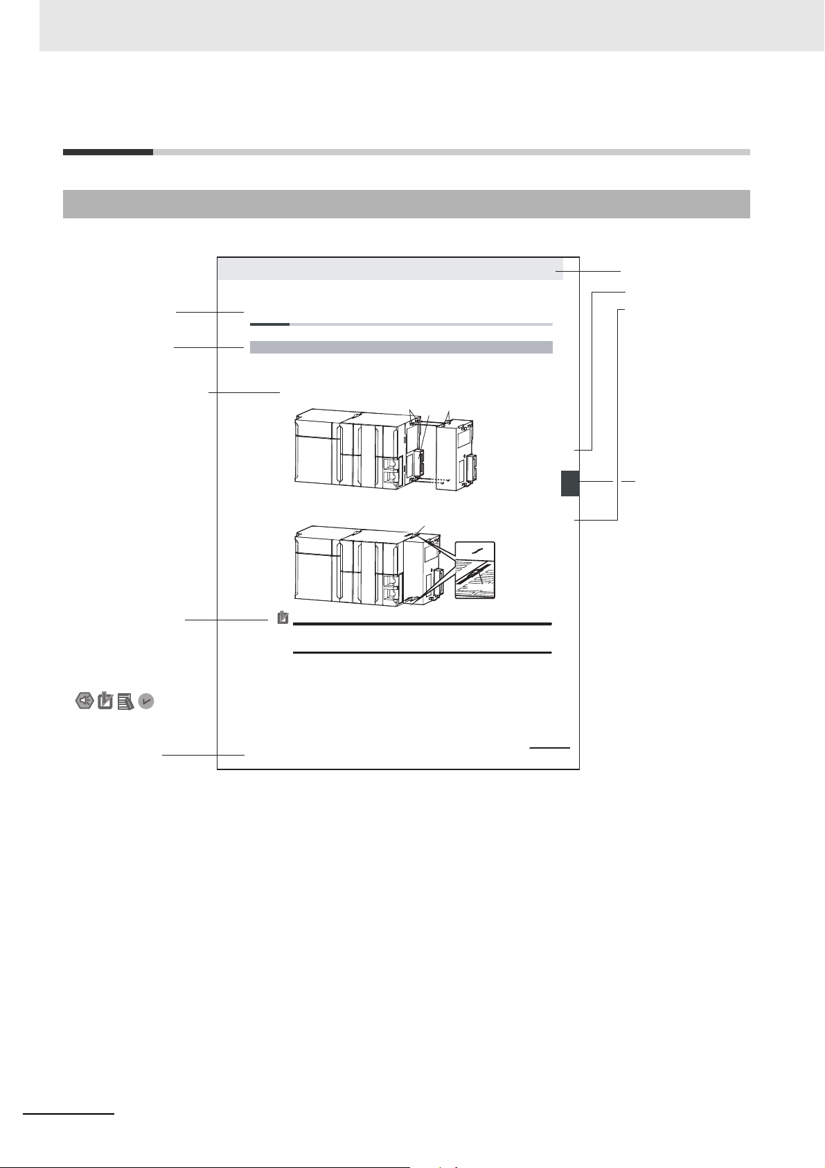
The Units that make up an NJ-series Controller can be connected simply by pressing the Units together
and locking the sliders by moving them toward the back of the Units. The End Cover is connected in the
same way to the Unit on the far right side of the Controller.
1 Join the Units so that the connectors fit exactly.
2 The yellow sliders at the top and bottom of eac h Unit lock the Units together. Move the sliders
toward the back of the Units as shown below until they click into place.
Precautions for Correct Use Precautions for Correct Use
4-3-1 Connecting Controller Components
Connector
Hook
Hook holes
Slider
Lock
Release
Move the sliders toward the back
until they lock into place.
Level 1 heading
Level 2 heading
Level 3 heading
Level 2 heading
A step in a procedure
Manual name
Special information
Level 3 heading
Page tab
Gives the current
headings.
Indicates a procedure.
Icons indicate
precautions, additional
information, or reference
information.
Gives the number
of the main section.
This illustration is provided only as a sample. It may not literally appear in this manual.
The sliders on the tops and bottoms of the Power Supply Unit, CPU Unit, I/O Units, Special I/O
Units, and CPU Bus Units must be completely locked (until they click into place) after connecting
the adjacent Unit connectors.
Manual Structure
Page Structure
The following page structure is used in this manual.
4
NY-series Industrial Panel PC / Industrial Box PC Motion Control User’s Manual (W559)
Page 7

Special Information
Special information in this manual is classified as follows:
Precautions for Safe Use
Precautions on what to do and what not to do to ensure safe usage of the product.
Precautions for Correct Use
Precautions on what to do and what not to do to ensure proper operation and performance.
Additional Information
Additional information to read as required.
This information is provided to increase understanding or make operation easier.
Note References are provided to more detailed or related information.
Manual Structure
Precaution on Terminology
In this manual, “download” refers to transferring data from the Sysmac Studio to the NY-series Controller and “upload” refers to transferring data from the NY-series Controller to the Sysmac Studio.
For the Sysmac Studio, synchronization is used to both upload and download data. Here, “synchronize”
means to automatically compare the data for the Sysmac Studio on the computer with the data in the
physical Controller and transfer the data in the direction that is specified by the user.
NY-series Industrial Panel PC / Industrial Box PC Motion Control User’s Manual (W559)
5
Page 8

Manual Structure
6
NY-series Industrial Panel PC / Industrial Box PC Motion Control User’s Manual (W559)
Page 9
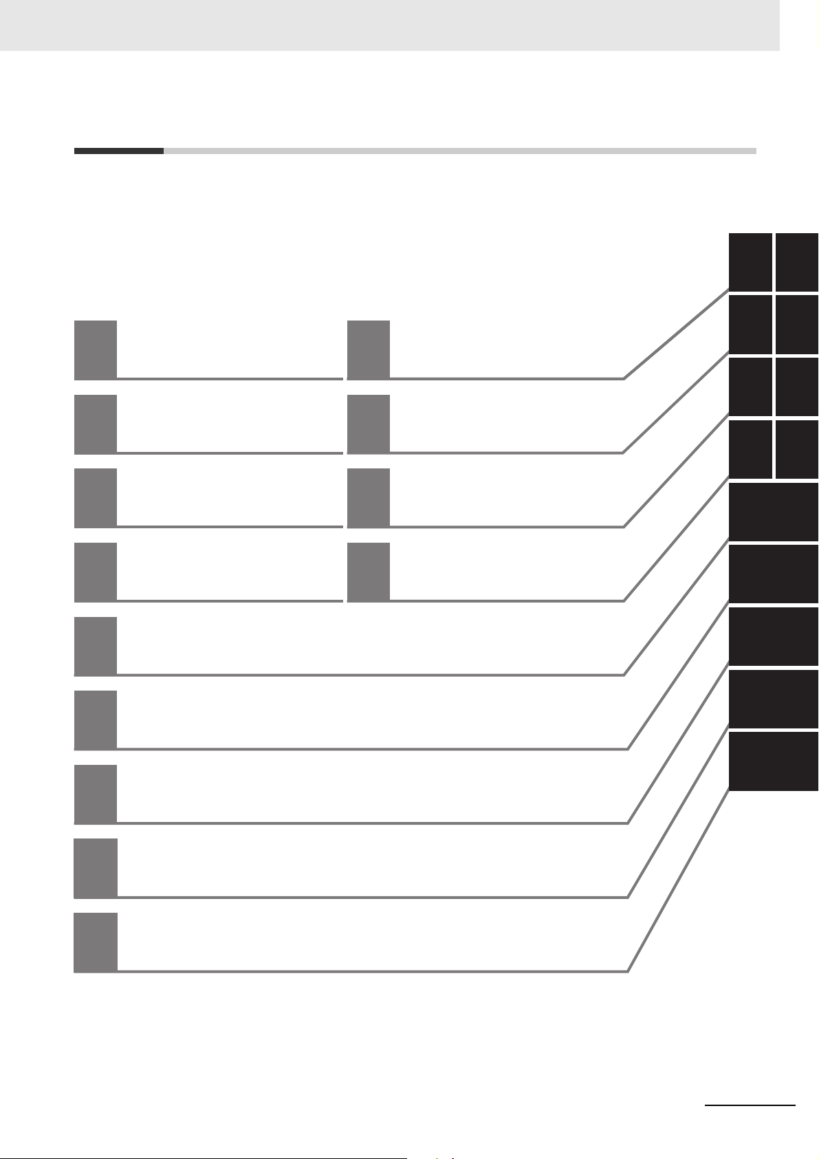
Sections in this Manual
1
10
2
11
3
4
A
5
6
7
8
9
1
10
2
11
3
4I
A
6
5
7
8
9
Sample Programming
Troubleshooting
Configuring Axes
and Axes Groups
Appendices
Checking Wiring from
the Sysmac Studio
Index
I
Motion Control Parameters
Motion Control Programming
Manual Operation
Homing
Motion Control Functions
Introduction to the
Motion Control
Function Module
Motion Control
Configuration and
Principles
Sections in this Manual
NY-series Industrial Panel PC / Industrial Box PC Motion Control User’s Manual (W559)
7
Page 10

Sections in this Manual
8
NY-series Industrial Panel PC / Industrial Box PC Motion Control User’s Manual (W559)
Page 11

CONTENTS
CONTENTS
Introduction............................................................................................................... 1
Relevant Manuals ..................................................................................................... 2
Manual Structure ...................................................................................................... 4
Sections in this Manual............................................................................................ 7
Terms and Conditions Agreement ........................................................................ 14
Safety Precautions ................................................................................................. 16
Precautions for Safe Use ....................................................................................... 17
Precautions for Correct Use .................................................................................. 18
Regulations and Standards ................................................................................... 19
Versions................................................................................................................... 20
Related Manuals ..................................................................................................... 22
Revision History ..................................................................................................... 25
Section 1 Introduction to the Motion Control Function Module
1-1 Features.................................................................................................................................... 1-2
1-2 System Configuration ............................................................................................................. 1-3
1-3 Basic Flow of Operation ......................................................................................................... 1-4
1-4 Specifications .......................................................................................................................... 1-6
1-4-1 General Specifications................................................................................................................ 1-6
1-4-2 Performance Specifications........................................................................................................ 1-6
1-4-3 Function Specifications............................................................................................................... 1-7
Section 2 Motion Control Configuration and Principles
2-1 Internal Configuration of the Controller Functions .............................................................. 2-2
2-2 Motion Control Configuration ................................................................................................ 2-3
2-3 Motion Control Principles....................................................................................................... 2-4
2-3-1 Controller Function Tasks ........................................................................................................... 2-4
2-3-2 Example of Task Operations for Motion Control ......................................................................... 2-8
2-4 EtherCAT Communications and Motion Control ................................................................ 2-12
2-4-1 CAN Application Protocol over EtherCAT (CoE) ...................................................................... 2-12
2-4-2 Relationship between EtherCAT Master Function Module and MC Function Module .............. 2-13
2-4-3 Relationship between Process Data Communications Cycle and Motion Control Period ........ 2-14
Section 3 Configuring Axes and Axes Groups
3-1 Axes .......................................................................................................................................... 3-2
3-1-1 Introduction to Axes.................................................................................................................... 3-2
NY-series Industrial Panel PC / Industrial Box PC Motion Control User’s Manual (W559)
9
Page 12

CONTENTS
3-1-2 Introduction to Axis Parameters..................................................................................................3-3
3-1-3 Introduction to Axis Variables...................................................................................................... 3-7
3-1-4 Specifying an Axis in the User Program......................................................................................3-9
3-2 Axis Setting Procedure ......................................................................................................... 3-10
3-2-1 Axis Configuration Procedure ...................................................................................................3-10
3-2-2 Setting Procedure .....................................................................................................................3-10
3-3 Axes Groups .......................................................................................................................... 3-19
3-3-1 Introduction to Axes Groups...................................................................................................... 3-19
3-3-2 Introduction to Axes Group Parameters....................................................................................3-20
3-3-3 Introduction to Axes Group Variables........................................................................................ 3-21
3-3-4 Specifying an Axes Group in the User Program........................................................................3-23
3-4 Setting Procedures for Axes Groups................................................................................... 3-24
3-4-1 Setting Procedure for an Axes Group .......................................................................................3-24
3-4-2 Setting Procedure .....................................................................................................................3-24
Section 4 Checking Wiring from the Sysmac Studio
4-1 Functions of the Sysmac Studio ............................................................................................ 4-2
4-1-1 MC Test Run Function.................................................................................................................4-2
4-1-2 Application Procedure .................................................................................................................4-4
4-1-3 Axis Parameter Setting Example ................................................................................................ 4-5
4-1-4 Starting the MC Test Run Function ............................................................................................. 4-6
4-2 Monitoring Sensor Signals ..................................................................................................... 4-7
4-3 Checking Motor Operation...................................................................................................... 4-8
4-3-1 Turning ON the Servo .................................................................................................................4-8
4-3-2 Jogging........................................................................................................................................4-8
4-3-3 Homing........................................................................................................................................4-9
4-3-4 Absolute Positioning.................................................................................................................. 4-10
4-3-5 Relative Positioning................................................................................................................... 4-11
Section 5 Motion Control Parameters
5-1 Introduction.............................................................................................................................. 5-2
5-2 Axis Parameters ...................................................................................................................... 5-5
5-2-1 Axis Parameters..........................................................................................................................5-5
5-2-2 Axis Basic Settings......................................................................................................................5-7
5-2-3 Unit Conversion Settings........................................................................................................... 5-10
5-2-4 Operation Settings .................................................................................................................... 5-17
5-2-5 Other Operation Settings ..........................................................................................................5-21
5-2-6 Limit Settings.............................................................................................................................5-22
5-2-7 Position Count Settings.............................................................................................................5-22
5-2-8 Servo Drive Settings .................................................................................................................5-24
5-2-9 Homing Settings........................................................................................................................5-25
5-2-10 Axis Parameter Setting Example ..............................................................................................5-26
5-3 Axes Group Parameters........................................................................................................5-29
5-3-1 Axes Group Parameters............................................................................................................ 5-29
5-3-2 Axes Group Basic Settings .......................................................................................................5-30
5-3-3 Axes Group Operation Settings ................................................................................................5-32
5-3-4 Enabling an Axes Group ........................................................................................................... 5-34
Section 6 Motion Control Programming
6-1 Introduction.............................................................................................................................. 6-2
6-2 Motion Control Instructions.................................................................................................... 6-3
6-2-1 Function Blocks for PLCopen® Motion Control .......................................................................... 6-3
6-2-2 Motion Control Instructions of the MC Function Module .............................................................6-3
10
NY-series Industrial Panel PC / Industrial Box PC Motion Control User’s Manual (W559)
Page 13

CONTENTS
6-3 State Transitions...................................................................................................................... 6-4
6-3-1 Status of the Motion Control Function Module............................................................................ 6-4
6-3-2 Axis States.................................................................................................................................. 6-5
6-3-3 Axes Group States...................................................................................................................... 6-7
6-4 Execution and Status of Motion Control Instructions.......................................................... 6-9
6-4-1 Basic Rules for Execution of Instructions ................................................................................... 6-9
6-4-2 Execution Timing Charts............................................................................................................6-11
6-4-3 Timing Chart for Re-execution of Motion Control Instructions .................................................. 6-14
6-4-4 Timing Chart for Multi-execution of Motion Control Instructions ............................................... 6-15
6-5 Positions ................................................................................................................................ 6-16
6-5-1 Types of Positions..................................................................................................................... 6-16
6-5-2 Valid Positions for Each Axis Type ........................................................................................... 6-17
6-6 System-defined Variables for Motion Control..................................................................... 6-18
6-6-1 Overview of System-defined Variables for Motion Control ....................................................... 6-18
6-6-2 System for System-defined Variables for Motion Control ......................................................... 6-21
6-6-3 Tables of System-defined Variables for Motion Control............................................................ 6-22
6-7 Cam Tables and Cam Data Variables................................................................................... 6-33
6-8 Programming Motion Controls............................................................................................. 6-37
6-9 Creating Cam Tables............................................................................................................. 6-39
Section 7 Manual Operation
7-1 Outline ...................................................................................................................................... 7-2
7-2 Turning ON the Servo.............................................................................................................. 7-3
7-2-1 Turning ON the Servo................................................................................................................. 7-3
7-2-2 Setting Axis Parameters ............................................................................................................. 7-4
7-2-3 Programming Example ............................................................................................................... 7-4
7-3 Jogging..................................................................................................................................... 7-5
7-3-1 Jogging Procedure...................................................................................................................... 7-5
7-3-2 Setting Axis Parameters ............................................................................................................. 7-6
7-3-3 Setting Example for Input Variables............................................................................................ 7-6
7-3-4 Programming Example ............................................................................................................... 7-7
Section 8 Homing
8-1 Outline ...................................................................................................................................... 8-2
8-2 Homing Procedure .................................................................................................................. 8-5
8-2-1 Setting Homing Parameters........................................................................................................ 8-5
8-2-2 Monitoring the Homing Operation............................................................................................. 8-12
8-3 Homing Operation ................................................................................................................. 8-13
8-4 Homing with an Absolute Encoder ...................................................................................... 8-14
8-4-1 Outline of Function.................................................................................................................... 8-15
8-4-2 Setting Procedure..................................................................................................................... 8-16
8-5 High-speed Homing............................................................................................................... 8-18
Section 9 Motion Control Functions
9-1 Single-axis Position Control................................................................................................... 9-3
9-1-1 Outline of Operation.................................................................................................................... 9-3
9-1-2 Absolute Positioning ................................................................................................................... 9-4
9-1-3 Relative Positioning .................................................................................................................... 9-4
9-1-4 Interrupt Feeding ........................................................................................................................ 9-5
9-1-5 Cyclic Synchronous Positioning.................................................................................................. 9-6
NY-series Industrial Panel PC / Industrial Box PC Motion Control User’s Manual (W559)
11
Page 14

CONTENTS
9-1-6 Stopping......................................................................................................................................9-6
9-1-7 Override Factors ....................................................................................................................... 9-11
9-2 Single-axis Synchronized Control ....................................................................................... 9-12
9-2-1 Overview of Synchronized Control............................................................................................9-12
9-2-2 Gear Operation ......................................................................................................................... 9-12
9-2-3 Positioning Gear Operation.......................................................................................................9-13
9-2-4 Cam Operation.......................................................................................................................... 9-14
9-2-5 Cam Tables ............................................................................................................................... 9-15
9-2-6 Synchronous Positioning........................................................................................................... 9-23
9-2-7 Combining Axes........................................................................................................................ 9-24
9-2-8 Master Axis Phase Shift............................................................................................................9-25
9-2-9 Slave Axis Position Compensation ...........................................................................................9-25
9-3 Single-axis Velocity Control .................................................................................................9-27
9-3-1 Velocity Control......................................................................................................................... 9-27
9-3-2 Cyclic Synchronous Velocity Control.........................................................................................9-28
9-4 Single-axis Torque Control ...................................................................................................9-29
9-5 Common Functions for Single-axis Control ....................................................................... 9-30
9-5-1 Positions....................................................................................................................................9-30
9-5-2 Velocity......................................................................................................................................9-32
9-5-3 Acceleration and Deceleration ..................................................................................................9-33
9-5-4 Jerk ...........................................................................................................................................9-35
9-5-5 Specifying the Operation Direction............................................................................................9-36
9-5-6 Re-executing Motion Control Instructions .................................................................................9-40
9-5-7 Multi-execution of Motion Control Instructions (Buffer Mode) ...................................................9-45
9-6 Multi-axes Coordinated Control ........................................................................................... 9-51
9-6-1 Outline of Operation..................................................................................................................9-51
9-6-2 Linear Interpolation ...................................................................................................................9-54
9-6-3 Circular Interpolation................................................................................................................. 9-55
9-6-4 Axes Group Cyclic Synchronous Positioning ............................................................................ 9-55
9-6-5 Stopping Under Multi-axes Coordinated Control.......................................................................9-56
9-6-6 Overrides for Multi-axes Coordinated Control...........................................................................9-57
9-7 Common Functions for Multi-axes Coordinated Control................................................... 9-59
9-7-1 Velocity Under Multi-axes Coordinated Control ........................................................................9-59
9-7-2 Acceleration and Deceleration Under Multi-axes Coordinated Control.....................................9-60
9-7-3 Jerk for Multi-axes Coordinated Control....................................................................................9-61
9-7-4 Re-executing Motion Control Instructions for Multi-axes Coordinated Control ......................... 9-62
9-7-5 Multi-execution (Buffer Mode) of Motion Control Instructions for Multi-axes Coordinated
Control.......................................................................................................................................9-63
9-8 Other Functions..................................................................................................................... 9-71
9-8-1 Changing the Current Position..................................................................................................9-71
9-8-2 Torque Limit...............................................................................................................................9-72
9-8-3 Latching.....................................................................................................................................9-72
9-8-4 Zone Monitoring ........................................................................................................................9-73
9-8-5 Software Limits..........................................................................................................................9-74
9-8-6 Following Error Monitoring ........................................................................................................ 9-75
9-8-7 Following Error Counter Reset..................................................................................................9-76
9-8-8 Axis Following Error Monitoring ................................................................................................9-76
9-8-9 In-position Check ......................................................................................................................9-77
9-8-10 Changing Axis Use.................................................................................................................... 9-79
9-8-11 Enabling Digital Cam Switch ..................................................................................................... 9-79
9-8-12 Displaying 3D Motion Monitor for User Coordinate System...................................................... 9-80
Section 10 Sample Programming
10-1 Overview of Sample Programming ...................................................................................... 10-2
10-1-1 Devices .....................................................................................................................................10-2
10-1-2 Installation and Wiring...............................................................................................................10-2
10-1-3 Setup.........................................................................................................................................10-2
10-2 Basic Programming Samples ............................................................................................... 10-3
12
NY-series Industrial Panel PC / Industrial Box PC Motion Control User’s Manual (W559)
Page 15

CONTENTS
10-2-1 Monitoring EtherCAT Communications and Turning ON Servos.............................................. 10-3
10-2-2 Interlocking Axis Operation with Master Control Instructions ................................................... 10-5
10-2-3 Error Monitoring and Error Resetting for Single-axis Operation and Synchronized Operation. 10-7
10-2-4 Error Monitoring and Error Resetting for Multi-axes Coordinated Operation............................ 10-9
10-2-5 Monitoring for Instruction Errors ............................................................................................. 10-15
10-2-6 Checking to See If Errors Are Reset....................................................................................... 10-17
10-2-7 Stopping Axes during Single-axis Operation .......................................................................... 10-19
10-2-8 Stopping an Axes Group in Coordinated Motion .................................................................... 10-23
10-2-9 Homing and Absolute Positioning........................................................................................... 10-29
10-2-10 Changing the Target Position by Re-execution of an Instruction............................................ 10-34
10-2-11 Interrupt Feeding .................................................................................................................... 10-40
10-2-12 Changing the Cam Table by Re-execution of an Instruction................................................... 10-44
10-2-13 Using a Cam Profile Curve to Correct the Sync Position........................................................ 10-53
10-2-14 Shifting the Phase of a Master Axis in Cam Motion................................................................ 10-63
10-2-15 Changing the Actual Position during Velocity Control............................................................. 10-71
10-2-16 Changing a Cam Data Variable and Saving the Cam Table ................................................... 10-77
10-2-17 Temporarily Changing Axis Parameters ................................................................................. 10-85
10-2-18 Updating the Cam Table End Point Index............................................................................... 10-89
Section 11 Troubleshooting
11-1 Overview of Errors ................................................................................................................ 11-2
11-1-1 How to Check for Errors ............................................................................................................11-3
11-1-2 Errors Related to the Motion Control Function Module..............................................................11-5
11-2 Error Causes and Remedies................................................................................................11-11
11-2-1 Preliminary Check Items..........................................................................................................11-11
11-2-2 Problems and Countermeasures.............................................................................................11-12
Appendices
A-1 Connecting the 1S-series Servo Drive ..................................................................................A-2
A-1-1 Wiring the Servo Drive................................................................................................................A-2
A-1-2 Servo Drive Settings...................................................................................................................A-2
A-2 Connecting the G5-series Servo Drive ................................................................................ A-11
A-2-1 Wiring the Servo Drive.............................................................................................................. A-11
A-2-2 Servo Drive Settings................................................................................................................. A-11
A-3 Connecting to Encoder Input Terminals..............................................................................A-22
A-3-1 Wiring to Encoder Input Terminals............................................................................................ A-22
A-3-2 Settings for Encoder Input Terminals........................................................................................A-22
A-4 Connecting to NX Units.........................................................................................................A-28
A-5 PDS State Transition .............................................................................................................A-29
A-5-1 PDS State Control Method........................................................................................................A-30
A-5-2 Main Circuit Power Supply OFF Detection ............................................................................... A-31
A-6 Terminology ...........................................................................................................................A-32
A-6-1 NY-series Controller..................................................................................................................A-32
A-6-2 Motion Control .......................................................................................................................... A-33
A-6-3 EtherCAT Communications ...................................................................................................... A-34
A-7 Version Information...............................................................................................................A-35
Index
NY-series Industrial Panel PC / Industrial Box PC Motion Control User’s Manual (W559)
13
Page 16

Terms and Conditions Agreement
Terms and Conditions Agreement
Warranty, Limitations of Liability
Warranties
Exclusive Warranty
Omron’s exclusive warranty is that the Products will be free from defects in materials and workmanship for a period of twelve months from the date of sale by Omron (or such other period expressed in
writing by Omron). Omron disclaims all other warranties, express or implied.
Limitations
OMRON MAKES NO WARRANTY OR REPRESENTATION, EXPRESS OR IMPLIED, ABOUT
NON-INFRINGEMENT, MERCHANTABILITY OR FITNESS FOR A PARTICULAR PURPOSE OF
THE PRODUCTS. BUYER ACKNOWLEDGES THAT IT ALONE HAS DETERMINED THAT THE
PRODUCTS WILL SUITABLY MEET THE REQUIREMENTS OF THEIR INTENDED USE.
Omron further disclaims all warranties and responsibility of any type for claims or expenses based
on infringement by the Products or otherwise of any intellectual property right.
Buyer Remedy
Omron’s sole obligation hereunder shall be, at Omron’s election, to (i) replace (in the form originally
shipped with Buyer responsible for labor charges for removal or replacement thereof) the non-complying Product, (ii) repair the non-complying Product, or (iii) repay or credit Buyer an amount equal
to the purchase price of the non-complying Product; provided that in no event shall Omron be
responsible for warranty, repair, indemnity or any other claims or expenses regarding the Products
unless Omron’s analysis confirms that the Products were properly handled, stored, installed and
maintained and not subject to contamination, abuse, misuse or inappropriate modification. Return of
any Products by Buyer must be approved in writing by Omron before shipment. Omron Companies
shall not be liable for the suitability or unsuitability or the results from the use of Products in combination with any electrical or electronic components, circuits, system assemblies or any other materials or substances or environments. Any advice, recommendations or information given orally or in
writing, are not to be construed as an amendment or addition to the above warranty.
See http://www.omron.com/global/ or contact your Omron representative for published information.
Limitation on Liability; Etc
OMRON COMPANIES SHALL NOT BE LIABLE FOR SPECIAL, INDIRECT, INCIDENTAL, OR CONSEQUENTIAL DAMAGES, LOSS OF PROFITS OR PRODUCTION OR COMMERCIAL LOSS IN ANY
WAY CONNECTED WITH THE PRODUCTS, WHETHER SUCH CLAIM IS BASED IN CONTRACT,
WARRANTY, NEGLIGENCE OR STRICT LIABILITY.
Further, in no event shall liability of Omron Companies exceed the individual price of the Product on
which liability is asserted.
14
NY-series Industrial Panel PC / Industrial Box PC Motion Control User’s Manual (W559)
Page 17

Application Considerations
Suitability of Use
Omron Companies shall not be responsible for conformity with any standards, codes or regulations
which apply to the combination of the Product in the Buyer’s application or use of the Product. At
Buyer’s request, Omron will provide applicable third party certification documents identifying ratings
and limitations of use which apply to the Product. This information by itself is not sufficient for a complete determination of the suitability of the Product in combination with the end product, machine, system, or other application or use. Buyer shall be solely responsible for determining appropriateness of
the particular Product with respect to Buyer’s application, product or system. Buyer shall take application responsibility in all cases.
NEVER USE THE PRODUCT FOR AN APPLICATION INVOLVING SERIOUS RISK TO LIFE OR
PROPERTY WITHOUT ENSURING THAT THE SYSTEM AS A WHOLE HAS BEEN DESIGNED TO
ADDRESS THE RISKS, AND THAT THE OMRON PRODUCT(S) IS PROPERLY RATED AND
INSTALLED FOR THE INTENDED USE WITHIN THE OVERALL EQUIPMENT OR SYSTEM.
Terms and Conditions Agreement
Programmable Products
Omron Companies shall not be responsible for the user’s programming of a programmable Product, or
any consequence thereof.
Disclaimers
Performance Data
Data presented in Omron Company websites, catalogs and other materials is provided as a guide for
the user in determining suitability and does not constitute a warranty. It may represent the result of
Omron’s test conditions, and the user must correlate it to actual application requirements. Actual performance is subject to the Omron’s Warranty and Limitations of Liability.
Change in Specifications
Product specifications and accessories may be changed at any time based on improvements and other
reasons. It is our practice to change part numbers when published ratings or features are changed, or
when significant construction changes are made. However, some specifications of the Product may be
changed without any notice. When in doubt, special part numbers may be assigned to fix or establish
key specifications for your application. Please consult with your Omron’s representative at any time to
confirm actual specifications of purchased Product.
Errors and Omissions
Information presented by Omron Companies has been checked and is believed to be accurate; however, no responsibility is assumed for clerical, typographical or proofreading errors or omissions.
NY-series Industrial Panel PC / Industrial Box PC Motion Control User’s Manual (W559)
15
Page 18

Safety Precautions
Safety Precautions
Refer to the following manuals for safety precautions.
• NY-series Industrial Box PC Hardware User’s Manual (Cat. No. W556)
• NY-series Industrial Panel PC Hardware User’s Manual (Cat. No. W557)
• NY-series Industrial Panel PC / Industrial Box PC Software User’s Manual (Cat. No. W558)
16
NY-series Industrial Panel PC / Industrial Box PC Motion Control User’s Manual (W559)
Page 19

Precautions for Safe Use
Refer to the following manuals for precautions for safe use.
• NY-series Industrial Box PC Hardware User’s Manual (Cat. No. W556)
• NY-series Industrial Panel PC Hardware User’s Manual (Cat. No. W557)
• NY-series Industrial Panel PC / Industrial Box PC Software User’s Manual (Cat. No. W558)
Precautions for Safe Use
NY-series Industrial Panel PC / Industrial Box PC Motion Control User’s Manual (W559)
17
Page 20

Precautions for Correct Use
Precautions for Correct Use
Refer to the following manuals for precautions for correct use.
• NY-series Industrial Box PC Hardware User’s Manual (Cat. No. W556)
• NY-series Industrial Panel PC Hardware User’s Manual (Cat. No. W557)
• NY-series Industrial Panel PC / Industrial Box PC Software User’s Manual (Cat. No. W558)
18
NY-series Industrial Panel PC / Industrial Box PC Motion Control User’s Manual (W559)
Page 21

Regulations and Standards
Conformance to EU Directives
Applicable Directives
• EMC Directives
Concepts
EMC Directive
OMRON devices that comply with EU Directives also conform to the related EMC standards so that
they can be more easily built into other devices or the overall machine. The actual products have
been checked for conformity to EMC standards.*
Whether the products conform to the standards in the system used by the customer, however, must
be checked by the customer. EMC-related performance of the OMRON devices that comply with EU
Directives will vary depending on the configuration, wiring, and other conditions of the equipment or
control panel on which the OMRON devices are installed. The customer must, therefore, perform
the final check to confirm that devices and the overall machine conform to EMC standards.
* Applicable EMC (Electromagnetic Compatibility) standards are as follows:
EMS (Electromagnetic Susceptibility): EN 61131-2
EMI (Electromagnetic Interference): EN 61131-2 (Radiated emission: 10-m regulations)
Regulations and Standards
Conformance to EU Directives
The NY-series Controllers comply with EU Directives. To ensure that the machine or device in which
the NY-series Controller is used complies with EU Directives, the Controller must be installed as follows:
• The NY-series Controller must be installed within a control panel.
• You must use the power supply in SELV specifications for the DC power supplies connected to
DC Power Supply Units and I/O Units.
• NY-series Controllers that comply with EU Directives also conform to the Common Emission Standard (EN 61000-6-4). Radiated emission characteristics (10-m regulations) may vary depending
on the configuration of the control panel used, other devices connected to the control panel, wiring, and other conditions.
You must therefore confirm that the overall machine or equipment complies with EU Directives.
Software Licenses and Copyrights
This product incorporates certain third party software. The license and copyright information associated with this software is available at http://www.fa.omron.co.jp/nj_info_e/.
NY-series Industrial Panel PC / Industrial Box PC Motion Control User’s Manual (W559)
19
Page 22
Versions
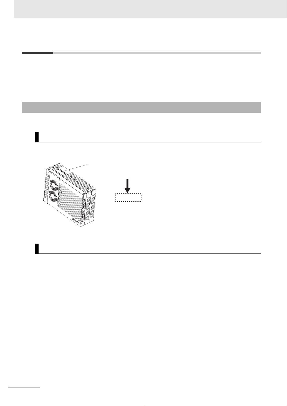
ID information indication
Unit version
Ver.1.
Versions
Hardware revisions and unit versions are used to manage the hardware and software in NY-series Controllers and EtherCAT slaves. The hardware revision or unit version is updated each time there is a
change in hardware or software specifications. Even when two Units or EtherCAT slaves have the
same model number, they will have functional or performance differences if they have different hardware revisions or unit versions.
Checking Versions
You can check versions on the ID information indications or with the Sysmac Studio.
Checking Unit Versions on ID Information Indications
The unit version is given on the ID information indication on the back side of the product.
The ID information on an NY-series NY52- Controller is shown below.
Checking Unit Versions with the Sysmac Studio
You can use the Sysmac Studio to check unit versions. The procedure is different for Units and for EtherCAT slaves.
Checking the Unit Version of an NY-series Controller
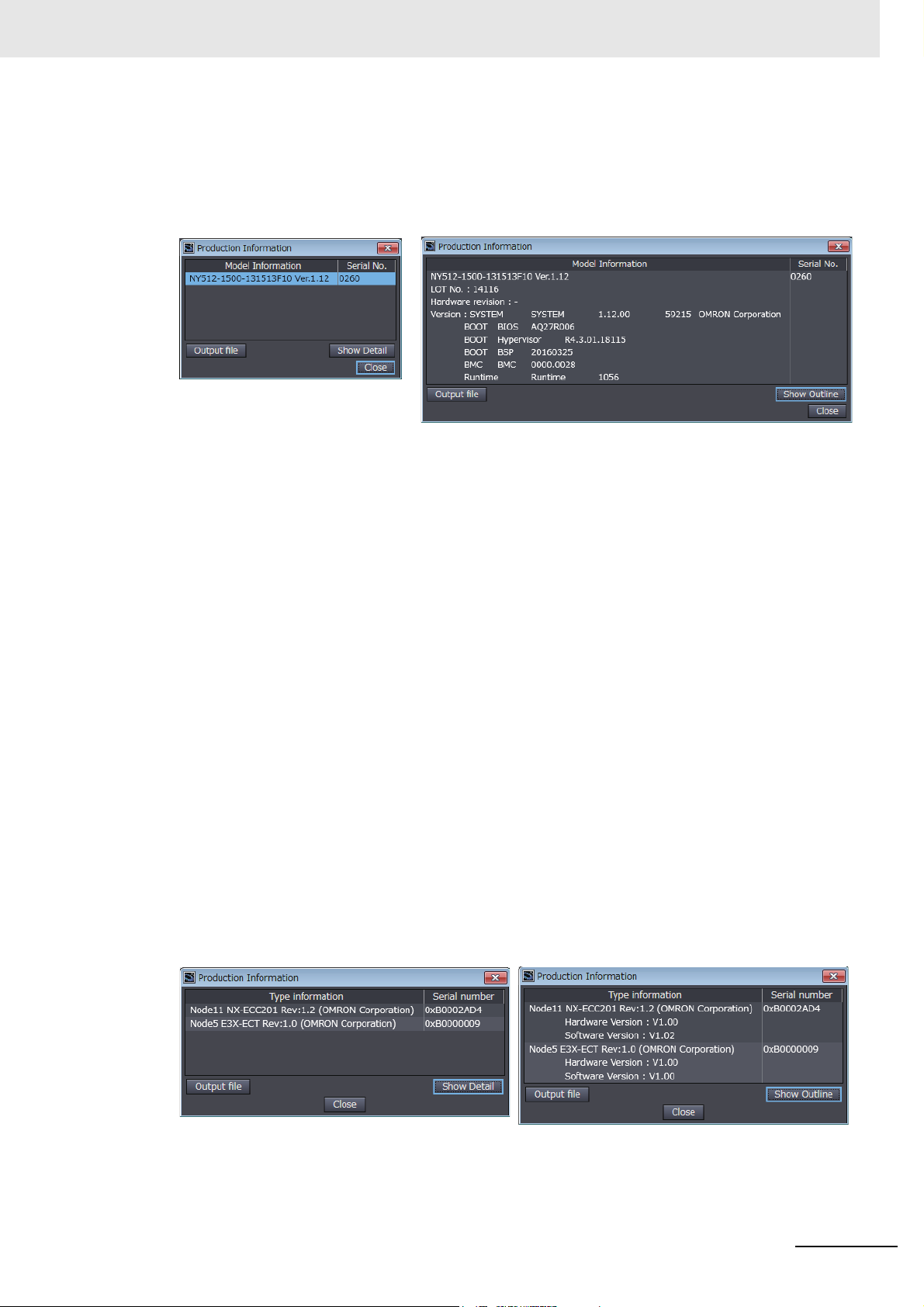
You can use the Production Information while the Sysmac Studio is online to check the unit version
of a Unit. You can only do this for the Controller.
• Right-click CPU Rack under Configurations and Setup − CPU/Expansion Racks in the Multiview Explorer and select Production Information.
The Production Information Dialog Box is displayed.
20
NY-series Industrial Panel PC / Industrial Box PC Motion Control User’s Manual (W559)
Page 23
Versions
Changing Information Displayed in Production Information Dialog Box
Click the Show Detail or Show Outline Button at the lower right of the Production Information Dialog Box.
The view will change between the production information details and outline.
Outline View Detail View
The information that is displayed is different for the Outline View and Detail View. The Detail View
displays the unit version, hardware revision, and other versions. The Outline View displays only the
unit version.
Checking the Unit Version of an EtherCAT Slave
You can use the Production Information while the Sysmac Studio is online to check the unit version
of an EtherCAT slave. Use the following procedure to check the unit version.
1 Double-click EtherCAT under Configurations and Setup in the Multiview Explorer. Or, right-
click EtherCAT under Configurations and Setup and select Edit from the menu.
The EtherCAT Tab Page is displayed.
2 Right-click the master on the EtherCAT Tab Page and select Display Production Information.
The Production Information Dialog Box is displayed.
The unit version is displayed after “Rev.”
Changing Information Displayed in Production Information Dialog Box
Click the Show Detail or Show Outline Button at the lower right of the Production Information Dialog Box.
The view will change between the production information details and outline.
Outline View Detail View
NY-series Industrial Panel PC / Industrial Box PC Motion Control User’s Manual (W559)
21
Page 24

Related Manuals
Related Manuals
The following are the manuals related to this manual. Use these manuals for reference.
Manual name Cat. No. Model numbers Application Description
NY-series
IPC Machine Controller
Industrial Panel PC Hardware
User’s Manual
NY-series
IPC Machine Controller
Industrial Box PC Hardware
User’s Manual
NY-series
IPC Machine Controller
Industrial Panel PC /
Industrial Box PC Setup
User’s Manual
NY-series
IPC Machine Controller
Industrial Panel PC /
Industrial Box PC Software
User’s Manual
NY-series
Instructions Reference
Manual
NY-series
IPC Machine Controller
Industrial Panel PC /
Industrial Box PC Motion
Control
User’s Manual
NY-series
Motion Control Instructions
Reference Manual
W557 NY532- Learning the basic
specifications of the
NY-series Industrial
Panel PCs, including
introductory information, designing, installation, and
maintenance.
Mainly hardware
information is provided.
W556 NY512- Learning the basic
specifications of the
NY-series Industrial
Box PCs, including
introductory information, designing, installation, and
maintenance.
Mainly hardware
information is provided.
W568 NY532-
NY512-
W558 NY532-
NY512-
W560 NY532-
NY512-
W559 NY532-
NY512-
W561 NY532-
NY512-
Learning about initial
setting of the NYseries Industrial PCs
and how to prepare
the Controller.
Learning how to program and set up the
Controller functions
of an NY-series
Industrial PC.
Learning detailed
specifications on the
basic instructions of
the NY-series Industrial PC.
Learning about
motion control settings and programming concepts of an
NY-series Industrial
PC.
Learning abou
specifications of the
motion contr
instructions of an NYseries Industrial PC.
t the
ol
An introduction to the entire NY-series system is provided along with the following information on the Industrial Panel PC.
• Features and system configuration
• Introduction
• Part names and functions
• General specifications
• Installation and wiring
• Maintenance and inspection
An introduction to the entire NY-series system is provided along with the following information on the Industrial Box PC.
• Features and system configuration
• Introduction
• Part names and functions
• General specifications
• Installation and wiring
• Maintenance and inspection
The following information is provided on an
introduction to the entire NY-series system.
• Two OS systems
• Initial settings
• Industrial PC Support Utility
• NYCompolet
• Industrial PC API
• Backup and recovery
The following information is provided on the
NY-series Controller functions.
• Controller operation
• Controller features
• Controller settings
• Programming based on IEC 61131-3 language specifications
The instructions in the instruction set (IEC
61131-3 specifications) are described.
The settings and operation of the Controller
and programming concepts for motion control
are described.
The motion control instructions are
described.
22
NY-series Industrial Panel PC / Industrial Box PC Motion Control User’s Manual (W559)
Page 25

Manual name Cat. No. Model numbers Application Description
NY-series
IPC Machine Controller
Industrial Panel PC /
Industrial Box PC Built-in EtherCAT® Port User’s Manual
NY-series
IPC Machine Controller
Industrial Panel PC /
Industrial Box PC Built-in
EtherNet/IP™ Port
User’s Manual
NJ/NY-series NC Integrated
Controller User’s Manual
NJ/NY-series
G code Instructions Reference Manual
NY-series
Troubleshooting Manual
Sysmac Studio Version 1
Operation Manual
CNC Operator
Operation Manual
NX-series
EtherCAT® Coupler Unit
User’s Manual
NX-series NX Units User’s
Manuals
NX-series Data Reference
Manual
W562 NY532-
NY512-
W563 NY532-
NY512-
O030 NJ501-5300
NY532-5400
O031 NJ501-5300
NY532-5400
W564 NY532-
NY512-
W504 SYSMAC
-SE2
O032 SYSMAC
-RTNC0D
W519 NX-ECC Learning how to use
W521 NX-ID
NX-IA
NX-OC
NX-OD
W522 NX-AD
NX-DA
NX-TS
W523 NX-PD1
NX-PF0
NX-PC0
NX-TBX
W524 NX-EC0
NX-ECS
NX-PG0
W525 NX- Referring to the list of
Using the built-in EtherCAT port in an NYseries Industrial PC.
Using the built-in EtherNet/IP port in an
NY-series Industrial
PC.
Performing numerical control with
NJ/NY-series Controllers.
Learning about the
specifications of the
G code/M code
instructions.
Learning about the
errors that may be
detected in an NYseries Industrial PC.
Learning about the
operating procedures and functions
of the Sysmac Studio.
Learning an introduction of the CNC Operator and how to use
it.
an NX-series EtherCAT Coupler Unit and
EtherCAT Slave Terminals.
Learning how to use
NX Units.
data required for NXseries unit system
configuration.
Information on the built-in EtherCAT port is
provided.
This manual provides an introduction and
provides information on the configuration,
features, and setup.
Information on the built-in EtherNet/IP port is
provided.
Information is provided on the basic setup,
tag data links, and other features.
Describes the functionality to perform the
numerical control.
The G code/M code instructions are
described.
Concepts on managing errors that may be
detected in an NY-series Controller and information on individual errors are described.
Describes the operating procedures of the
Sysmac Studio.
An introduction of the CNC Operator, installation procedures, basic operations, connection
operations, and operating procedures for
main functions are described.
The following items are described: the overall
system and configuration methods of an EtherCAT Slave Terminal (which consists of an
NX-series EtherCAT Coupler Unit and NX
Units), and information on hardware, setup,
and functions to set up, control, and monitor
s through Et
NX Unit
Describe the hardware, setup methods, and
functions of the NX Units.
Manuals are available for the following Units.
Digital I/O Units, Analog I/O Units, System
Units, and Position Interface Units.
Provides the list of data required for system
configuration including the power consumption and weight of each NX-series Unit.
Related Manuals
herCAT.
NY-series Industrial Panel PC / Industrial Box PC Motion Control User’s Manual (W559)
23
Page 26

Related Manuals
Manual name Cat. No. Model numbers Application Description
GX-series EtherCAT Slave
Units User’s Manual
AC Servomotors/Servo
Drives 1S-series with Built-in
EtherCAT® Communications
User’s Manual
AC Servomotors/Servo
Drives G5-series with Built-in
EtherCAT® Communications
User’s Manual
W488 GX-ID
GX-OD
GX-OC
GX-MD
GX-AD
GX-DA
GX-EC
XWT-ID
XWT-OD
I586 R88M-1
R88D-1SN-ECT
I573 R88M-K
R88D-KN-ECT-R
I576 R88M-K
R88D-KN-ECT
I577 R88L-EC-
R88D-KN-ECT-L
Learning how to use
the EtherCAT remote
I/O terminals.
Learning how to use
the Servomotors/Servo Drives
with built-in EtherCAT
Communications.
Learning how to use
the Servomotors/Servo Drives
with built-in EtherCAT
Communications.
Describes the hardware, setup methods, and
functions of the EtherCAT remote I/O terminals.
Describes the hardware, setup methods and
functions of the Servomotors/Servo Drives
with built-in EtherCAT Communications.
Describes the hardware, setup methods and
functions of the Servomotors/Servo Drives
with built-in EtherCAT Communications.
The linear motor type model and the model
dedicated for position controls are available
in G5-series.
24
NY-series Industrial Panel PC / Industrial Box PC Motion Control User’s Manual (W559)
Page 27

Revision History
W559-E1-03
Revision code
Cat. No.
A manual revision code appears as a suffix to the catalog number on the front and back covers of the
manual.
Revision code Date Revised content
01 September 2016 Original production
02 April 2017 Corrected mistakes.
03 October 2017 Corrected mistakes.
Revision History
NY-series Industrial Panel PC / Industrial Box PC Motion Control User’s Manual (W559)
25
Page 28

Revision History
26
NY-series Industrial Panel PC / Industrial Box PC Motion Control User’s Manual (W559)
Page 29

Introduction to the Motion Control
Function Module
This section describes the features, system configuration, and application flow for the
Motion Control Function Module.
1-1 Features . . . . . . . . . . . . . . . . . . . . . . . . . . . . . . . . . . . . . . . . . . . . . . . . . . . . . 1-2
1-2 System Configuration . . . . . . . . . . . . . . . . . . . . . . . . . . . . . . . . . . . . . . . . . . 1-3
1-3 Basic Flow of Operation . . . . . . . . . . . . . . . . . . . . . . . . . . . . . . . . . . . . . . . . 1-4
1-4 Specifications . . . . . . . . . . . . . . . . . . . . . . . . . . . . . . . . . . . . . . . . . . . . . . . . . 1-6
1-4-1 General Specifications . . . . . . . . . . . . . . . . . . . . . . . . . . . . . . . . . . . . . . . . . . . 1-6
1-4-2 Performance Specifications . . . . . . . . . . . . . . . . . . . . . . . . . . . . . . . . . . . . . . . 1-6
1-4-3 Function Specifications . . . . . . . . . . . . . . . . . . . . . . . . . . . . . . . . . . . . . . . . . . 1-7
1
NY-series Industrial Panel PC / Industrial Box PC Motion Control User’s Manual (W559)
1-1
Page 30

1 Introduction to the Motion Control Function Module
Additional Information
Additional Information
1-1 Features
The Motion Control Function Module (sometimes abbreviated to “MC Function Module”) is a function
module of the Software that is embedded in the Real-Time OS of the Industrial PC. The MC Function
Module can perform motion control for up to 64 axes through the EtherCAT port that is built into the
Industrial PC. Cyclic communications are performed with Servo Drives and other devices that are connected to the EtherCAT port to enable high-speed, high-precision machine control.
Motion Control Instructions Based on PLCopen
The motion control instructions of the MC Function Module are based on motion control function blocks
that are standardized by PLCopen
ing, interpolation control, synchronized control (e.g., of electronic cams), velocity control, and torque
control. You can set the velocity, acceleration rate, deceleration rate, and jerk each time a motion control instruction is executed to flexibly control operation according to the application.
• PLCopen
PLCopen® is an association that promotes IEC 61131-3. It has its headquarters in Europe and a
world-wide membership. PLCopen
program interface for the languages specified in IEC 61131-3 (JIS B 3503).
•Jerk
Jerk is the rate of change in the acceleration rate or deceleration rate. If you specify the jerk, the
velocity graph will form an S-curve for acceleration and deceleration.
®
®
. These instructions allow you to program single-axis PTP position-
®
standardizes function blocks for motion control to define a
®
Data Transmission Using EtherCAT Communications
The MC Function Module can be combined with OMRON 1S-series Servo Drives with built-in EtherCAT
communications or G5-series Servo Drives with built-in EtherCAT communications to enable exchange
of all control information with high-speed data communications. The various control commands are
transmitted via data communications. That means that the Servomotor’s operational performance is
maximized without being limited by interface specifications, such as the response frequency of the
encoder feedback pulses. You can use the Servo Drive’s various control parameters and monitor data
on a host controller to unify management of system information.
What Is EtherCAT?
EtherCAT is an open high-speed industrial network system that conforms to Ethernet (IEEE
802.3). Each node achieves a short cycle time by transmitting Ethernet frames at high speed. A
mechanism that allows sharing clock information enables high-precision synchronized control
with low communications jitter.
1-2
NY-series Industrial Panel PC / Industrial Box PC Motion Control User’s Manual (W559)
Page 31

1 Introduction to the Motion Control Function Module
Additional Information
1-2 System Configuration
The MC Function Module receives sensor signal status from devices and control panels. It receives
commands from the motion control instructions that are executed in the user program. It uses both of
these to perform motion control with the Servo Drives, Encoder Input Terminals, and NX-series Position
Interface Units.
1-2 System Configuration
Motion Control Configuration
The EtherCAT network configuration, the Slave Terminal configurations for EtherCAT Coupler Units,
and the Sysmac Studio are used for the MC Function Module.
• EtherCAT Network Configuration
The MC Function Module performs control for Servo Drives and Encoder Input Terminals through
the EtherCAT master port that is built into the CPU Unit. The EtherCAT network configuration is
used to perform precise motion control in a fixed period with very little deviation.
• Slave Terminal Configurations of EtherCAT Coupler Units
The MC Function Module uses the Position Interface Units that are mounted under an EtherCAT
Coupler Unit to output motor control pulses and read encoder inputs. You can also use this configuration to perform precise motion control in a fixed period with very little deviation.
• Sysmac Studio
The Sysmac Studio is connected to the peripheral USB port on the CPU Unit with a commercially
available USB cable. You can also connect it to the built-in EtherNet/IP port on the CPU Unit with
Ethernet cable.
Sysmac Studio
LAN
EtherNet/IP
NY-series Controller
1
EtherCAT Network
Built-in EtherCAT port
Built-in EtherNet/IP port
Positive limit input
Negative limit input
Immediate stop input
Home proximity input
Home input
External latch input, etc.
EtherCAT
Slave Terminal
1S-series Servo Drives with Built-in
EtherCAT Communications
G5-series Servo Drives with Built-in
EtherCAT Communications
Configuration
Encoder Input
Terminal
Some of the functions of the MC Function Module are different when NX-series Position Interface Units are used. Refer to the NX-series Position Interface Units User’s Manual (Cat. No.
W524) for details.
NY-series Industrial Panel PC / Industrial Box PC Motion Control User’s Manual (W559)
1-3
Page 32

1 Introduction to the Motion Control Function Module
Additional Information
NY-series Industrial Panel PC / Industrial Box
PC Software User’s Manual (Cat. No. W558)
Section 3 Configuring Axes and Axes Groups
Section 4 Checking Wiring from the Sysmac
Studio
NY-series Industrial Panel PC / Industrial Box
PC Software User’s Manual (Cat. No. W558)
Sysmac Studio Version 1 Operation Manual
(Cat. No. W504)
1-3 Basic Flow of Operation
This section provides the basic procedure to perform motion control with the MC Function Module.
START
Create a project.Setup
Create the EtherCAT Network Configuration.
Add axes.
Assign the axes.
Set the axis parameters.
Set the Controller Setup.
Transferring
Checking Wiring
Checking Operation
Continues to on next page.
* The EtherCAT Network Configuration can be set online if you are connected to the physical network.
The EtherCAT Network Configuration can be selected offline if the hardware is not available yet.
Transfer the project to the Controller.
Open the MC Test Run Tab Page.
Monitor input signals to check the wiring.
Perform jogging.
A
*
Refer to the NX-series Position Interface Units User’s Manual (Cat. No. W524) for the procedures for the NX-series Position Interface Units.
1-4
NY-series Industrial Panel PC / Industrial Box PC Motion Control User’s Manual (W559)
Page 33

1 Introduction to the Motion Control Function Module
END
A
Programming
Manual operation
Homing
Programming
Debugging
Operation
Maintenance
Write a program to perform jogging.
Jog the axes with the user program.
Program the motion controls.
Define the homes of the Servomotor axes to
control.
Error?
Yes
No
Read the error code.
Remove the cause of the error and clear the error.
Operate the Controller and the machine.
Perform periodic maintenance.
Section 6 Motion Control Programming
Section 7 Manual Operation
Section 8 Homing
Section 6 Motion Control Programming
Section 10 Sample Programming
Section 11 Troubleshooting
Section 9 Motion Control
Functions
1-3 Basic Flow of Operation
1
NY-series Industrial Panel PC / Industrial Box PC Motion Control User’s Manual (W559)
1-5
Page 34

1 Introduction to the Motion Control Function Module
1-4 Specifications
This section gives the specifications of the MC Function Module.
1-4-1 General Specifications
General specifications conform to the general specifications of the NY-series Controller.
Refer to the NY-series Industrial Panel PC Hardware User’s Manual (Cat. No. W557) or NY-series
Industrial Box PC Hardware User’s Manual (Cat. No. W556) for details.
1-4-2 Performance Specifications
The following table describes the performance specifications for each type of Industrial PCs.
Item
Number of
controlled
axes
Maximum number of axes groups 32 axes groups
Override factors 0.00% or 0.01% to 500.00%
Motion control period The same control period as that is used for the process data
Multi-motion Not supported.
Cams Number of
*1 This is the total for all axis types. Refer to Axis Types on page 5-8 for details on axis types.
*2 This is the total number of axes whose axis type is set to Servo Axis or Encoder Axis and axis use is set to Used Axis.
Maximum number of controlled axes
Maximum number of used real axes
Maximum number of axes for single-axis
control
Maximum number of axes for linear interpolation axis control
Number of axes for circular interpolation
axis control
Maximum points per cam
cam data
points
Maximum number of cam tables 640 tables
table
Maximum points for all
cam tables
*1
*2
15 14 13
64 axes 32 axes 16 axes
64 axes 32 axes 16 axes
64 axes 32 axes 16 axes
4 axes per axes group
2 axes per axes group
communications cycle for EtherCAT.
65,535 points
1,048,560 points
NY52-
1-6
NY-series Industrial Panel PC / Industrial Box PC Motion Control User’s Manual (W559)
Page 35

1 Introduction to the Motion Control Function Module
1-4-3 Function Specifications
The following table describes the functions that are supported for connections to OMRON control
devices.
Item Description
Controllable Servo Drives OMRON 1S-series Servo Drives with built-in EtherCAT
communications or G5-series Servo Drives with built-in
*1
EtherCAT communications
Controllable encoder input terminals OMRON GX-series GX-EC0211/EC0241 EtherCAT
Remote I/O Terminals
Controllable Position Interface Units
Control method Control commands using EtherCAT communications
Control modes Position control, Velocity control, and Torque control
Unit conversions Position units Pulse, mm, μm, nm, degree, and inch
Positions that can be managed Command positions and actual positions
Axis types Servo axes, Virtual servo axes, Encoder axes, and Virtual
Position command values Negative or positive long reals (LREAL) or 0 (command
Velocity command values Negative or positive long reals (LREAL) or 0 (command
Acceleration command values and deceleration command values
Jerk command values
*3
Electronic gear ratio Pulse per motor rotation/travel distance per motor rotation,
OMRON NX-EC0 Incremental Encoder Input Units
OMRON NX-ECS SSI Input Units
OMRON NX-PG0 Pulse Output Units
or (Pulse per motor rotation × Motor gear ratio)/(Work
travel distance per rotation × Work gear ratio)
encoder axes
*4
)
units
units/s)
Positive long reals (LREAL) or 0 (command units/s
Positive long reals (LREAL) or 0 (command units/s
*2
2
)
3
)
1-4 Specifications
1
1-4-3 Function Specifications
NY-series Industrial Panel PC / Industrial Box PC Motion Control User’s Manual (W559)
1-7
Page 36

1 Introduction to the Motion Control Function Module
Item Description
Single axes Single-axis posi-
tion control
Single-axis velocity control
Single-axis torque
control
Single-axis synchronized control
Single-axis manual
operation
Absolute positioning Positioning is performed for a target position that is speci-
fied with an absolute value.
Relative positioning Positioning is performed for a specified travel distance
from the command current position.
Interrupt feeding Positioning is performed for a specified travel distance
from the position where an interrupt input was received
from an external input.
Cyclic synchronous absolute positioning
Velocity control Velocity control is performed in Position Control Mode.
Cyclic synchronous
velocity control
Torque control The torque of the motor is controlled.
Starting cam operation A cam motion is performed using the specified cam table.
Ending cam operation The cam motion for the axis that is specified with the input
Starting gear operation A gear motion with the specified gear ratio is performed
Positioning gear operation
Ending gear operation The specified gear motion or positioning gear motion is
Synchronous positioning Positioning is performed in sync with a specified master
Master axis phase shift The phase of a master axis in synchronized control is
Combining axes The command positions of two axes are added or sub-
Powering the Servo The Servo in the Servo Drive is turned ON to enable axis
Jogging An axis is jogged at a specified target velocity.
A command position is output each control period in Position Control Mode.
A velocity command is output each control period in Velocity Control Mode.
parameter is ended.
between a master axis and slave axis.
A gear motion with the specified gear ratio and sync position is performed between a master axis and slave axis.
ended.
axis.
shifted.
tracted and the result is output as the command position.
motion.
1-8
NY-series Industrial Panel PC / Industrial Box PC Motion Control User’s Manual (W559)
Page 37

1 Introduction to the Motion Control Function Module
Item Description
Single axes Auxiliary functions
for single-axis control
Axes groups Multi-axes coordi-
nated control
Auxiliary functions
for multi-axes coordinated control
Resetting axis errors Axes errors are cleared.
Homing A motor is operated and the limit signals, home proximity
signal, and home signal are used to define home.
Homing with parameters The parameters are specified, the motor is operated, and
the limit signals, home proximity signal, and home signal
are used to define home.
High-speed homing Positioning is performed for an absolute target position of
0 to return to home.
Stopping An axis is decelerated to a stop.
Immediately stopping An axis is stopped immediately.
Setting override factors The target velocity of an axis can be changed.
Changing the current
position
Enabling external latches The position of an axis is recorded when a trigger occurs.
Disabling external latches The current latch is disabled.
Zone monitoring You can monitor the command position or actual position
Enable Digital Cam
Switch
Monitoring axis following
error
Resetting the following
error
Torque limit The torque control function of the Servo Drive can be
Changing axis use The Axis Use axis parameter can be temporarily changed.
Start velocity You can set the initial velocity when axis motion starts.
Absolute linear interpolation
Relative linear interpolation
Circular 2D interpolation Circular interpolation is performed for two axes.
Axes group cyclic synchronous absolute positioning
Resetting axes group
errors
Enabling axes groups Motion of an axes group is enabled.
Disabling axes groups Motion of an axes group is disabled.
Changing the axes in an
axes group
Stopping axes groups All axes in interpolated motion are decelerated to a stop.
Immediately stopping
axes groups
Setting axes group override factors
Reading axes group positions
The command current position or actual current position of
an axis can be changed to any position.
of an axis to see when it is within a specified range (zone).
The digital outputs are turned ON or turned OFF depending on the axis position.
You can monitor whether the difference between the command positions or actual positions of two specified axes
exceeds a threshold value.
The error between the command current position and
actual current position is set to 0.
enabled or disabled and the torque limits can be set to
control the output torque.
Linear interpolation is performed to a specified absolute
position.
Linear interpolation is performed to a specified relative
position.
A positioning command is output each control period in
Position Control Mode.
Axes group errors and axis errors are cleared.
The Composition Axes parameter in the axes group
parameters can be overwritten temporarily.
All axes in interpolated motion are stopped immediately.
The blended target velocity is changed during interpolated
motion.
The command current positions and actual current positions of an axes group can be read.
1-4 Specifications
1
1-4-3 Function Specifications
NY-series Industrial Panel PC / Industrial Box PC Motion Control User’s Manual (W559)
1-9
Page 38

1 Introduction to the Motion Control Function Module
Item Description
Common
items
Auxiliary
functions
External interface signals The Servo Drive input signals listed on the right are used.
*5
Cams
Parameters Writing MC settings Some of the axis parameters or axes group parameters
Count modes You can select either Linear Mode (finite length) or Rotary
Unit conversions You can set the display unit for each axis according to the
Acceleration/deceleration control
In-position check You can set an in-position range and in-position check
Stop method You can set the stop method to the immediate stop input
Re-execution of motion control instructions You can change the input variables for a motion control
Multi-execution of motion control instructions
(Buffer Mode)
Continuous axes group motions (Transition
Mode)
Monitoring functions
Absolute encoder support You can use an OMRON 1S-series Servomotor or G5-
Input signal logic inversion You can inverse the logic of immediate stop input signal,
Setting cam table properties
Saving cam tables The cam table that is specified with the input parameter is
Generating cam tables The cam table that is specified with the input parameter is
Changing axis parameters
Automatic acceleration/deceleration control
Changing the acceleration and deceleration
rates
Software limits The movement range of an axis is monitored.
Following error The error between the command current value and the
Velocity, acceleration
rate, deceleration rate,
torque, interpolation
velocity, interpolation
acceleration rate, and
interpolation deceleration rate
The end point index of the cam table that is specified in
the input parameter is changed.
saved in non-volatile memory in the Industrial PC.
generated from the cam property and cam node.
are overwritten temporarily.
You can access and change the axis parameters from the
user program.
Mode (infinite length).
machine.
Jerk is set for the acceleration/deceleration curve for an
axis motion or axes group motion.
You can change the acceleration or deceleration rate even
during acceleration or deceleration.
time to confirm when positioning is completed.
signal or limit input signal.
instruction during execution and execute the instruction
again to change the target values during operation.
You can specify when to start execution and how to connect the velocities between operations when another
motion control instruction is executed during operation.
You can specify the Transition Mode for multi-execution of
instructions for axes group operation.
actual current value is monitored for an axis.
You can set and monitor warning values for each axis and
each axes group.
series Servomotor with an Absolute Encoder to eliminate
the need to perform homing at startup.
positive limit input signal, negative limit input signal, or
home proximity input signal.
Home signal, home proximity signal, positive limit signal,
negative limit signal, immediate stop signal, and interrupt
input signal
*6
1-10
*1 Unit version 2.1 or later is recommended for G5-series Cylinder-type Servo Drives. Unit version 1.1 or later is
recommended for G5-series Linear Motor Types.
*2 The recommended unit version is 1.1 or later.
NY-series Industrial Panel PC / Industrial Box PC Motion Control User’s Manual (W559)
Page 39

1 Introduction to the Motion Control Function Module
*3 Some of the functions of the MC Function Module are different when NX-series Position Interface Units are
used. Refer to the NX-series Position Interface Units User’s Manual (Cat. No. W524) for details.
*4 Positions can be set within a 40-bit signed integer range when converted to pulses.
*5 You can create the cam table with the Cam Editor in the Sysmac Studio or with the Generate Cam Table
instruction in the user program. Specify the master axis phase and the slave axis displacement. You can
change the phase pitch for each range. Cam data can be overwritten from the user program.
*6 Application is possible when you use an absolute external scale for an OMRON G5-series Linear Motor Type
Servo Drive with built-in EtherCAT communications.
1-4 Specifications
1
1-4-3 Function Specifications
NY-series Industrial Panel PC / Industrial Box PC Motion Control User’s Manual (W559)
1-11
Page 40

1 Introduction to the Motion Control Function Module
1-12
NY-series Industrial Panel PC / Industrial Box PC Motion Control User’s Manual (W559)
Page 41

Motion Control Configuration and
Principles
This section outlines the internal structure of the Controller functions and describes the
configuration and principles of the MC Function Module.
2-1 Internal Configuration of the Controller Functions . . . . . . . . . . . . . . . . . . 2-2
2-2 Motion Control Configuration . . . . . . . . . . . . . . . . . . . . . . . . . . . . . . . . . . . . 2-3
2-3 Motion Control Principles . . . . . . . . . . . . . . . . . . . . . . . . . . . . . . . . . . . . . . . 2-4
2-3-1 Controller Function Tasks . . . . . . . . . . . . . . . . . . . . . . . . . . . . . . . . . . . . . . . . 2-4
2-3-2 Example of Task Operations for Motion Control . . . . . . . . . . . . . . . . . . . . . . . 2-8
2-4 EtherCAT Communications and Motion Control . . . . . . . . . . . . . . . . . . . . 2-12
2-4-1 CAN Application Protocol over EtherCAT (CoE) . . . . . . . . . . . . . . . . . . . . . . 2-12
2-4-2 Relationship between EtherCAT Master Function Module
and MC Function Module . . . . . . . . . . . . . . . . . . . . . . . . . . . . . . . . . . . . . . . . 2-13
2-4-3 Relationship between Process Data Communications Cycle
and Motion Control Period . . . . . . . . . . . . . . . . . . . . . . . . . . . . . . . . . . . . . . . 2-14
2
NY-series Industrial Panel PC / Industrial Box PC Motion Control User’s Manual (W559)
2-1
Page 42

2 Motion Control Configuration and Principles
2-1 Internal Configuration of the
Controller Functions
This section provides an overview of the internal mechanisms of the NY-series Controller. The Controller functions have the following software configuration. The Motion Control Function Module is a software module that performs motion control.
Motion Control Function
Module
PLC Function Module
* Refer to the NY-series Industrial Panel PC / Industrial Box PC Software User’s Manual (Cat. No. W558) for
details on other Function Modules.
The PLC Function Module runs on top of the OS. The other Function Modules run on top of the PLC
Function Module. A description of each Function Module is given in the following table.
Function Module name Abbreviation Description
PLC Function Module PLC This module manages overall scheduling, executes
Motion Control Function Module MC This module performs motion control according to
EtherCAT Master Function Module ECAT This module communicates with the EtherCAT
EtherCAT Master Function
Module
OS
the user program, sends commands to the Motion
Control Function Module, and provides interfaces to
USB and the Virtual SD Memory Card.
the commands from motion control instructions that
are executed in the user program. It sends data to
the EtherCAT Master Function Module.
slaves as the EtherCAT master.
Other Function
Modules
*
2-2
Note Refer to the NY-series Industrial Panel PC / Industrial Box PC Software User’s Manual (Cat. No. W558) for
details on other Function Modules.
This manual provides the specifications and operating procedures for the Motion Control Function Module (sometimes abbreviated to “MC Function Module”). Refer to the other NY-series user’s manuals as
required when using the MC Function Module in an application.
NY-series Industrial Panel PC / Industrial Box PC Motion Control User’s Manual (W559)
Page 43

2 Motion Control Configuration and Principles
Additional Information
NY-series Controller
A feedback system is not configured.
A feedback system is configured.
Servo Drive
User program MC Function
Module
EtherCAT Master
Function Module
EtherCAT
communications
Communications
processing
Command
interpretation
Data processing
Motion
control
instruction
Communica-
tions
processing
Status
Position
control
Velocity
control
Torque
control
Command
interpretation
M
E
2-2 Motion Control Configuration
A control system built with Servo Drives generally controls motor operation with a semi-closed loop.
The semi-closed loop uses an encoder attached to the motor to detect the amount of rotation that has
been performed by the motor in response to the command value. This is provided as feedback of the
machine’s travel distance. The following error between the command value and actual motor rotation is
calculated and control is performed to bring the following error to zero.
In a machine configuration that uses the MC Function Module, no feedback information is provided for
the commands from the user program in the Controller functions. A feedback system is built into the
Servo Drive.
2-2 Motion Control Configuration
2
• When motion control instructions are executed in the user program, the MC Function Module inter-
• The MC Function Module then performs motion control processing at a fixed period based on the
• The command values are sent by using PDO communications during each process data communica-
• The Servo Drive performs position loop control, velocity loop control, and torque loop control based
• The encoder’s current value and the Servo Drive status are sent to the NY-series Controller during
prets the resulting commands.
results of the command interpretation. It generates command values to send to the Servo Drive. The
following command values are generated: target position, target velocity, and target torque.
tions cycle of EtherCAT communications.
on the command values received during each process data communications cycle of EtherCAT communications.
each process data communications cycle of EtherCAT communications.
• Motion control processing and process data communications in EtherCAT communications
are performed during the same time period.
• The MC Function Module controls the Servo Drive, which contains the position control loop,
velocity control loop, and torque control loop.
• Refer to the NX-series Position Interface Units User’s Manual (Cat. No. W524) for information
on the configuration of the NX-series Position Interface Units.
NY-series Industrial Panel PC / Industrial Box PC Motion Control User’s Manual (W559)
2-3
Page 44

2 Motion Control Configuration and Principles
2-3 Motion Control Principles
This section provides information on the Controller function tasks and how they relate to motion control.
2-3-1 Controller Function Tasks
Tasks are attributes of programs that determine the execution conditions and sequence of the programs. The Controller functions support the following tasks.
Type of task Task name
Tasks that execute programs at a fixed period Primary periodic task
Priority-16, -17, and -18 periodic tasks
Tasks that execute programs only once when the execution conditions for the tasks are met
Refer to the NY-series Industrial Panel PC / Industrial Box PC Software User’s Manual (Cat. No. W558)
for details on programs, tasks, and setting methods.
Event task (execution priority: 8 and 48)
Types of Tasks and Task Priority
The NY-series Controller can execute the user program with a single task or multiple tasks.
Tasks have an execution priority. Tasks with the highest execution priority are executed first. If the execution conditions are met for another task with a higher execution priority while a task is under execution, the task with the higher execution priority is given priority in execution. The following table lists the
tasks in which you can use motion control instructions and the task priorities for the NY-series Controller. You cannot use motion control instructions in event tasks.
Typ e o f ta s k
Primary
periodic task
Periodic tasks 0 or 1
Number of
tasks
1 4 This task executes I/O refreshing, programs, and motion
Priority Operation
control in the specified task period. This task has the highest
execution priority of all tasks and can be executed quickly and
precisely. Therefore, this task is best suited for situations when
synchronized control or highly responsive control is required.
Use the primary periodic task to execute all control with a
single task.
16
These tasks execute programs and I/O refreshing in the
specified task period. The execution period for this priority-16
periodic task is longer than the execution period of the primary
periodic task. Therefore, periodic tasks are used to execute
programs.
In the priority-16 periodic task, you can write the user program
for some slaves and Units that refresh I/O in the primary
periodic task.
For example, synchronized control and control requiring a fast
response time are placed in the primary periodic task. Overall
device control is separately placed in a priority-16 periodic task.
2-4
Note The NY-series Controller has some periodic tasks with an execution priority of 17 or 18. However, you can-
not use motion control instructions in these tasks. These tasks also do not perform I/O refreshing.
NY-series Industrial Panel PC / Industrial Box PC Motion Control User’s Manual (W559)
Page 45

2 Motion Control Configuration and Principles
Precautions for Correct UsePrecautions for Correct Use
Additional Information
IO UPG
MC
IO UPG
MC
IO UPG
MC
IO UPG
MC
IO UPG
MC
IO UPG IO UPGUPG UPG
(A)
(B)
(C)
Task period (t×4)
Primary
periodic task
Priority-16
periodic task
Primray period (t)
• Motion control instructions can be used in the primary periodic task and in a priority-16 peri-
odic task.
• If motion control instructions are used in any other tasks, an error will occur when the user pro-
gram is built on the Sysmac Studio.
Task Assignment
• Axes and axes groups can be assigned to the primary periodic task. The I/O device task that is
assigned to an axis must be the same type of task that is assigned to the axis.
• You can execute motion control instructions from the user program that is operated in the priority-16
periodic task for the axes and axes groups that are assigned to the primary periodic task.
Refer to Section 3 Configuring Axes and Axes Groups for details on axes and axes groups.
2-3 Motion Control Principles
2
2-3-1 Controller Function Tasks
Basic Operation of Tasks
Overall Task Operation
The primary periodic task and periodic tasks operate based on the task period of the primary periodic task (also known as the primary period). The primary periodic task includes operations such as
system common processing and motion control in addition to I/O refreshing and user program execution. Processing of motion control instructions in the programs is executed during the next motion
control (MC) period after the END instruction is executed in the task.
Symbol Description
IO I/O refreshing
UPG User program execution
MC Motion control
(A) A dotted line represents a transition to another task.
(B) A dashed-dotted line means that processing for that
task has been interrupted.
(C) A double line means that all processing for that task
has been completed.
NY-series Industrial Panel PC / Industrial Box PC Motion Control User’s Manual (W559)
2-5
Page 46

2 Motion Control Configuration and Principles
Task execution time
Task period (= primary period)
I/O refresh
Refresh
executed.
Control processing
Output data processing
Input data processing
System common processing 1
Motion control
System common processing 2
User program
execution
Operation of the Primary Periodic Task
Processing Processing Contents
Output data processing • Output refresh data is created for Output Units that execute I/O refreshing.
• If forced refreshing is set, the forced refreshing values are reflected in the
output refresh data.
Refresh execution • This process exchanges data with I/O.
Input data processing • Whether the condition expression for event task execution is met or not is
determined.
• Input refresh data is loaded from Input Units that execute I/O refreshing.
• If forced refreshing is set, the forced refreshing values are reflected in the
input refresh data that was read.
System common processing 1 • Processing for exclusive control of variables in tasks is performed when
accessing tasks are set.
• Motion input processing is performed.
• Data tracing processing (sampling and trigger checking) is performed.
User program execution • Programs assigned to tasks are executed in the order that they are
assigned.
Motion control 1
System common processing 2 • Processing for exclusive control of variables in tasks is performed when
*2
• The motion control commands from the motion control instructions in the
programs in the primary periodic task and priority-16 periodic task are executed.
• Motion output processing is performed.
refreshing tasks are set.
• Processing for variables accessed from outside of the Controller is per-
formed to maintain concurrency with task execution (executed for the variable access time that is set in the Task Settings).
• If there is processing for EtherNet/IP tag data links and refreshing tasks are
set for the tags (i.e., variables with a Network Publish attribute), variable
access processing is performed.
*1
*3
*1 The Servo Drive status, axis current values, and other motion control system-defined variables are updated
*2 For the system-defined variables of the axes that are assigned to Motion control 1, _MC_AX[0-63] are used.
*3 Data is sent to the Servo Drives during I/O refreshing in the next primary periodic task.
2-6
according to data received from the Servo Drives.
Similarly, for the system-defined variables of the axes groups, _MC_GRP[0-31] are used.
Refer to 3-1-3 Introduction to Axis Variables for the system-defined variables of axes and 3-3-3 Introduction to
Axes Group Variables for the system-defined variables of axes groups.
NY-series Industrial Panel PC / Industrial Box PC Motion Control User’s Manual (W559)
Page 47

2 Motion Control Configuration and Principles
Operation of a Priority-16 Periodic Task
You can refresh I/O in the priority-16 periodic task.
Task period
Task execution time
Task processing time
**
I/O refresh
Refresh
Output data processing
* The CPU Unit will temporarily interrupt the execution of a task in order to execute a task with a higher execution
priority.
Control
processing
executed.
Input data processing
System common
processing 1
User program
execution
Task processing time
Control
processing
User program
execution
System common
processing 2
Task Period
For a single task, the primary period, which is the task period for the primary periodic task, is the standard period for execution. In this case, the primary period is automatically used as the motion control
period. (It is also the same as the process data communications cycle for EtherCAT communications.)
2-3 Motion Control Principles
2
2-3-1 Controller Function Tasks
Periodic task execution is synchronized with the primary period. Set the task period of a periodic task
as an integer multiple of the primary period.
For example, if the primary period is 1 ms, then you can set the task period of a priority-16 periodic task
to 4 ms. In that case, the start of the period for the primary periodic task and the priority-16 periodic task
will match once every four primary periods.
Refer to the NY-series Industrial Panel PC / Industrial Box PC Software User’s Manual (Cat. No. W558)
for details on the task period.
Valid Task Periods for NY-series Controller
The following table lists the possible combinations of primary periodic task and priority-16 periodic
task periods for the NY-series Controller.
Task Valid task periods
Primary periodic task 500 µs to 8 ms (specify in increments of
250 µs)
Priority-16 periodic task 1 ms to 100 ms (specify in increments of
250 µs)
NY-series Industrial Panel PC / Industrial Box PC Motion Control User’s Manual (W559)
2-7
Page 48

2 Motion Control Configuration and Principles
Additional Information
IN
UPG
FB
IO MC UPG
FB
IO MC
Primary period Primary period
Execution of motion control instructions
Servo
Execution command
Slave A
Primary
periodic task
2-3-2 Example of Task Operations for Motion Control
Motion control instructions can be used in the primary periodic task, in a priority-5 periodic task, or in a
priority-16 periodic task. This section provides examples of task operations.
Using Motion Control Instructions in the Primary Periodic Task
If high-speed motion control is required, place the motion control instructions (FB) in the primary periodic task.
1
Loading Data
The input data from the EtherCAT slaves (slave A) is loaded during the I/O refresh (IO).
2
Instruction Execution
The motion control instructions (FB) are executed based on the data that was loaded during
user program execution (UPG).
The output variables of the motion control instructions are refreshed at this point.
3
Command Generation
Motion processing according to the motion control instructions (FB) that were executed is performed during motion control (MC) immediately after user program execution in the primary
periodic task. During this processing, execution commands for the Servo Drives and other
devices are generated.
4
Sending Commands
The execution commands that were generated are sent to the Servo Drive or other device
during the I/O refresh (IO) in the next period.
All instructions from inputs to execution command outputs to the Servo Drive or other device are
processed quickly in this task. We recommend placing all motion control instructions in the primary periodic task.
2-8
NY-series Industrial Panel PC / Industrial Box PC Motion Control User’s Manual (W559)
Page 49

2 Motion Control Configuration and Principles
Primary period
Execution of motion control instructions
Servo
Execution command
Priority-16
periodic task
Task period (primary period × 3)
Primary
periodic task
Slave A
IN
UPG
FB
UPGIO MC UPGIO MC UPGIO MC UPGIO MC UPGIO MC
Using Motion Control Instructions in a Priority-16 Periodic Task
If high speed motion control is not required and/or your user program is too large, place motion control
instructions in a priority-16 periodic task.
Timing of Processing
Motion control processing (MC) for the motion control instructions (FB) that are executed in the
same task period as the priority-16 periodic task are performed at the same time. Therefore, processing for multiple axes can be simultaneously executed or stopped.
2-3 Motion Control Principles
2
2-3-2 Example of Task Operations for Motion Control
Primary
periodic task
Priority-16
periodic task
Slave A
IN
Primary period
IO MC UPGIO MC UPGIO MC UPGIO MC UPGIO MC
UPG
UPG
FB
Execution of motion control instructions
Task period (primary period × 3)
1
Loading Data
Servo
Execution command
The input data from the EtherCAT slaves (slave A) is loaded during the I/O refresh (IO).
2
Instruction Execution
The motion control instructions (FB) are executed based on the data that was loaded during
user program execution (UPG) in the priority-16 periodic task.
The output variables of the motion control instructions are refreshed at this point.
3
Command Generation
Motion control instructions (FB) are executed in the task period of the priority-16 periodic task
according to the motion control instructions (FB) that were executed. Motion processing is performed during motion control processing (MC) in the next primary periodic task after the periodic
task. During this processing, execution commands for the Servo Drives or other devices are
generated.
4
Sending Commands
The execution commands that were generated are sent to the Servo Drive or other device
during the I/O refresh (IO) in the next period.
NY-series Industrial Panel PC / Industrial Box PC Motion Control User’s Manual (W559)
2-9
Page 50

2 Motion Control Configuration and Principles
Precautions for Correct UsePrecautions for Correct Use
Additional Information
UPG
FB
UPG
IO MC
UPG
IO MC
UPG
IO MC
UPG
IO MC
*3
UPG
IO MC
UPG
I/O
OUT
Primary period
Execution of motion control instructions
*2
Servo
Execution
command
Priority-16
periodic task
Task period (primary period × 3)
Primary
periodic task
Values of
Axis
Variable
are read
*1
Axis Variable Update Timing
Axis Variables are system-defined variables for some of the axis parameters and for the monitor
information, such as the actual position and error information for the axes controlled by the MC
Function Module.
If you access an Axis Variable of the primary periodic task during the priority-16 periodic task, the
values of the variable that were read at the start of the priority-16 periodic task are used.
Also, the values of an Axis Variable are not written when a motion control instruction (FB) is executed. They are written in motion control processing (MC) at the start of the next priority-16 periodic
task.
*1 The values of an Axis Variable of the primary periodic task are read at the start of user program execution for
the priority-16 periodic task.
*2 The values of an Axis Variable are not written when a motion control instruction (FB) is executed in the priority-
16 periodic task.
*3 The values are written during this motion control processing (MC).
• When motion control instructions are placed in a priority-16 periodic task, the response time of
the Servo Drive or other device will increase if the task period of the priority-16 periodic task is
lengthened.
• Make sure that all axes can be stopped safely for emergency stops, including emergency
stops commanded from external devices.
• The execution timing of motion control instructions in a priority-16 periodic task is not the same
as the execution timing for I/O control. Design the user program to allow for this.
For information on Axis Variables, refer to 3-1-3 Introduction to Axis Variables.
2-10
NY-series Industrial Panel PC / Industrial Box PC Motion Control User’s Manual (W559)
Page 51

2 Motion Control Configuration and Principles
Precautions for Correct UsePrecautions for Correct Use
Additional Information
UPG
FB1
UPG
IO MC
UPG
IO MC
UPG
IO MC
UPG
IO MC
UPG
IO MC
FB2 FB2 FB2 FB2
FB1: MC_MoveAbsolute
FB2: MC_MoveRelative
Execution command for MC_MoveRelative
Primary period
Servo
Priority-16
periodic task
Task period (primary period × 3)
Primary
periodic task
The instruction is buffered for
multi-execution of instructions.
Using Motion Control Instructions in Two Different Types of Tasks
If you have processes that require high-speed motion control and processes that do not require highspeed motion control for the same axis, you can place the motion control instructions (FB) both in the
primary periodic task and in a priority-16 periodic task.
If motion control instructions (FB) are executed in both tasks within the period of the priority-16 periodic
task, the MC Function Module will perform motion processing for instructions in the primary periodic
task first.
For example, the MC_MoveAbsolute instruction is executed in the priority-16 periodic task. Then, the
MC_MoveRelative is executed for the same axis in the primary periodic task. The operation for this is
shown below.
• The MC Function Module will execute MC_MoveRelative first. MC_MoveAbsolute is executed with
multi-execution of instructions.
2-3 Motion Control Principles
2
2-3-2 Example of Task Operations for Motion Control
The values of output variables for a motion control instruction and the values of system-defined variables for motion control will change during the I/O refresh of the task that executed the instruction.
Therefore, you may notice different behavior depending on the task if you use motion control instructions for the same axis in different tasks. Make sure that you thoroughly understand the processes of
each task before you start to develop your user program.
• If you include motion control instructions for the same axis in both the primary periodic task
and the priority-16 periodic task, pay close attention to the following when you develop your
user program: the execution order of the motion control instructions, the timing of updates for
system-defined variables for motion control, and the output timing of command values.
• If you use system-defined variables for motion control for the same axis in multiple tasks, pay
close attention to the differences in timing for updating system-defined variables for motion
control when you develop your user program.
For information on multi-execution of instructions, refer to 9-5-7 Multi-execution of Motion Con-
trol Instructions (Buffer Mode).
NY-series Industrial Panel PC / Industrial Box PC Motion Control User’s Manual (W559)
2-11
Page 52
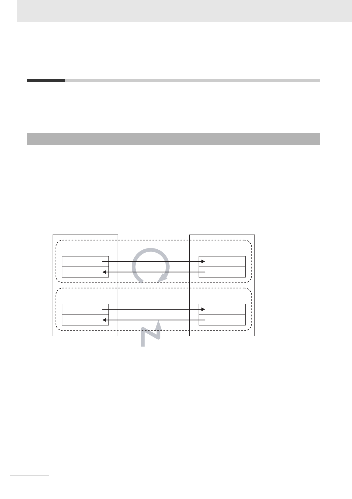
2 Motion Control Configuration and Principles
2-4 EtherCAT Communications and
Motion Control
The MC Function Module controls Servo Drives, counters, and NX-series Position Interface Units
through the PDO communications of the EtherCAT Master Function Module embedded in the RealTime OS of the Industrial PC. This section describes EtherCAT communications and other items related
to the MC Function Module.
2-4-1 CAN Application Protocol over EtherCAT (CoE)
The MC Function Module exchanges data with the slaves on EtherCAT using the CAN application protocol over EtherCAT (CoE). With CoE, the parameters and control information held by the slaves are
specified according to data specifications of the object dictionary (OD). To communicate the data
between the Controller (communications master) and slaves, two methods are used: process data
objects (PDOs), which periodically exchange data in realtime, and service data objects (SDOs), which
exchange data when required.
The MC Function Module uses PDO communications for commands to refresh I/O data, such as data
for Servomotor position control, on a fixed control period. It uses SDO communications for commands
to read and write data at specified times, such as for parameter transfers.
Controller
(communications master)
PDO communications
SDO communications
EtherCAT
communications lines
Executed periodically.
Output data
Input data
Write data
Read data
Executed for requests.
Slaves
2-12
NY-series Industrial Panel PC / Industrial Box PC Motion Control User’s Manual (W559)
Page 53

2 Motion Control Configuration and Principles
Additional Information
2-4-2 Relationship between EtherCAT Master Function Module and MC
Function Module
The NY-series Controller can perform sequence control and motion control through connections to EtherCAT slaves.
Sequence Control
• I/O ports for configuration slaves are automatically created when you create the EtherCAT Config-
uration in EtherCAT Tab Page in the Sysmac Studio.
• You use the I/O Map Tab Page in the Sysmac Studio to assign device variables.
• Perform sequence control through instructions other than motion control instructions.
Motion Control
• I/O ports for configuration slaves are automatically created when you create the EtherCAT Config-
uration in EtherCAT Tab Page in the Sysmac Studio.
• Create Axis Variables in Motion Control Setup View and assign the EtherCAT slaves for which
motion control is performed.
• Perform motion control through motion control instructions.
The following devices can be assigned to Axis Variables: EtherCAT slave Servo Drives, Encoder Input
Terminals, and NX-series Position Interface Units.
2-4 EtherCAT Communications and Motion
Control
2
2-4-2 Relationship between EtherCAT Master Function Module and MC Function Module
• Commands are not sent directly through PDO communications to an EtherCAT slave or NX-
series Position Interface Unit that is assigned to an Axis Variable for instructions other than
motion control instructions. However, the status of such an EtherCAT slave can be accessed
indirectly through the Axis Variables.
• You can use SDO communications to read and write the objects of EtherCAT slaves and NX-
series Position Interface Units that are assigned to axes variables. However, do not use SDO
communications to write objects that are mapped to PDO communications. If you do, the operation of the slaves will depend on slave specifications. For OMRON slaves, SDO communications will result in errors.
• If EtherCAT slave Servo Drives, Encoder Input Terminals, and NX-series Position Interface
Units are not assigned to axes variables, you must execute sequence control for them in the
same way as for general-purpose EtherCAT slaves.
NY-series Industrial Panel PC / Industrial Box PC Motion Control User’s Manual (W559)
2-13
Page 54

2 Motion Control Configuration and Principles
Slaves
Controller functions
Processing in slaveEtherCAT
Motion control processing
by MC Function Module
Execution of user
program in PLC
Function Module
Sequence control period
*1
Motion control
period
*1
Communications cycle
*1
Data refresh
period in slave
(depends on the slave)
CPU Unit
MC Function Module
Axis Variables
Other processing
Device variables
Profile processing
Synchronization
processing
Task period
Task period
EtherCAT
Master
Function
Module
EtherCAT
I/O ports
EtherCAT
EtherCAT
slaves
EtherCAT slaves
Servo Driver or
encoder input
terminal
Position Interface
Units
Sequence
control
Motion control
User program in PLC
Function Module
Instructions
other than
motion control
instructions
User-created
function block
Motion control
instructions
Motion control
instructions
Executed
Executed
Executed
Executed
Executed
2-4-3 Relationship between Process Data Communications Cycle and
Motion Control Period
The PLC Function Module sends motion control commands to the MC Function Module when motion
control instructions are executed in the user program. The MC Function Module then performs motion
control processing based on those commands and sends the results of processing as commands to the
EtherCAT’s Servo Drive or other device.
This type of data exchange is updated as shown in the following processing period.
• Primary period = Motion control period = Process data communications cycle for EtherCAT communi-
cations
*1 Since the sequence control period is primary period, the motion control period and the communications
2-14
cycle are also primary period.
NY-series Industrial Panel PC / Industrial Box PC Motion Control User’s Manual (W559)
Page 55

Configuring Axes and Axes
Groups
This section describes the concept of axes and axes groups, the settings for axes that
are required for the MC test run function to operate on the Sysmac Studio, and the
instructions for creating and configuring axes and axes groups using the Sysmac Studio.
3-1 Axes . . . . . . . . . . . . . . . . . . . . . . . . . . . . . . . . . . . . . . . . . . . . . . . . . . . . . . . . . 3-2
3-1-1 Introduction to Axes . . . . . . . . . . . . . . . . . . . . . . . . . . . . . . . . . . . . . . . . . . . . . 3-2
3-1-2 Introduction to Axis Parameters . . . . . . . . . . . . . . . . . . . . . . . . . . . . . . . . . . . . 3-3
3-1-3 Introduction to Axis Variables . . . . . . . . . . . . . . . . . . . . . . . . . . . . . . . . . . . . . 3-7
3-1-4 Specifying an Axis in the User Program . . . . . . . . . . . . . . . . . . . . . . . . . . . . . 3-9
3-2 Axis Setting Procedure . . . . . . . . . . . . . . . . . . . . . . . . . . . . . . . . . . . . . . . . 3-10
3-2-1 Axis Configuration Procedure . . . . . . . . . . . . . . . . . . . . . . . . . . . . . . . . . . . . 3-10
3-2-2 Setting Procedure . . . . . . . . . . . . . . . . . . . . . . . . . . . . . . . . . . . . . . . . . . . . . 3-10
3-3 Axes Groups . . . . . . . . . . . . . . . . . . . . . . . . . . . . . . . . . . . . . . . . . . . . . . . . . 3-19
3-3-1 Introduction to Axes Groups . . . . . . . . . . . . . . . . . . . . . . . . . . . . . . . . . . . . . 3-19
3-3-2 Introduction to Axes Group Parameters . . . . . . . . . . . . . . . . . . . . . . . . . . . . 3-20
3-3-3 Introduction to Axes Group Variables . . . . . . . . . . . . . . . . . . . . . . . . . . . . . . 3-21
3-3-4 Specifying an Axes Group in the User Program . . . . . . . . . . . . . . . . . . . . . . 3-23
3-4 Setting Procedures for Axes Groups . . . . . . . . . . . . . . . . . . . . . . . . . . . . . 3-24
3-4-1 Setting Procedure for an Axes Group . . . . . . . . . . . . . . . . . . . . . . . . . . . . . . 3-24
3-4-2 Setting Procedure . . . . . . . . . . . . . . . . . . . . . . . . . . . . . . . . . . . . . . . . . . . . . 3-24
3
NY-series Industrial Panel PC / Industrial Box PC Motion Control User’s Manual (W559)
3-1
Page 56

3 Configuring Axes and Axes Groups
3-1 Axes
This section describes the axes that are used in a MC Function Module.
3-1-1 Introduction to Axes
In a motion control system, the targets of motion control are called axes. An axis can be an actual
Servo Drive or other device or encoder connected using EtherCAT or it can be a virtual Servo Drive or
encoder within the MC Function Module.
The MC Function Module supports the axis types that are given in the following table.
Axis type Description
Servo axis These axes are used by the EtherCAT slave Servo Drives and NX-series
Virtual servo axis These are virtual axes that exist only inside the MC Function Module. They
Encoder axis These axes are used by the EtherCAT slave Encoder Input Terminals and
Virtual encoder axis These axes are used virtually for encoder operation. A virtual encoder axis
*1
Position Interface Units.
other devices.
If you use NX-series Position Interface Units, you can assign more than
one device, such as a Pulse Output Unit and Digital Input Unit, to the same
axis.
are not used by actual Servo Drives. For example, they are used as master
axes for synchronizing control.
NX-series Position Interface Units.
actual encoder input terminal or other device. Encoder axes are assigned
to actual encoder input terminals. If one encoder input terminal contains
two encoder inputs, the individual encoder inputs will act as one axis.
is used temporarily in place of an encoder axis when there is no physical
encoder.
*2
They are assigned to actual Servo Drives or
*1
An encoder axis is assigned to an
*1 Refer to 1-4-3 Function Specifications for the controllable devices.
*2 Virtual encoder axes are used in combination with motion control instructions that update the actual position of
the virtual encoder axis. Counting cannot be used with versions of the MC Function Module that do not support
these instructions.
3-2
NY-series Industrial Panel PC / Industrial Box PC Motion Control User’s Manual (W559)
Page 57

3 Configuring Axes and Axes Groups
The following elements are related to the axes of the MC Function Module.
The number of elements provided is the same as the maximum number of controlled axes for each
model. The maximum number of controlled axes varies depending on the model. Refer to 1-4-3 Func-
tion Specifications on page 1-7 for details.
Configuration element Description Page
Axis parameters The axis parameters set the maximum velocity, jogging, homing,
and other items for the axes operations controlled by the MC Function Module. Use the Sysmac Studio to set the axis parameters.
Axis Variables Axis Variables are system-defined variables for the actual position,
error information, and other monitor information for axes controlled
by the MC Function Module. Axis Variables are created when you
add an axis from the Multiview Explorer of the Sysmac Studio. The
names of the Axis Variables (called the Axis Variable names) are set
here.
Specifying axes in the
user program
In the user program, motion control is implemented with motion control instructions. Motion control instructions that perform single-axis
control are used to create axis commands. To control an axis with
axis commands, specify the Axis Variable name of the systemdefined variable or the Axis Variable name that was set with the Sysmac Studio for the Axis in-out variable of the instruction.
P. 3 - 3
P. 3 - 7
P. 3 - 9
3-1 Axes
3
3-1-2 Introduction to Axis Parameters
3-1-2 Introduction to Axis Parameters
Axis Parameters
Classification Parameter name
Axis Basic
Settings
Unit Conversion
Settings
Axis Number
Axis Use
Axis Type
Input Device/Output Device
Unit of Display
Command Pulse Count Per Motor Rotation
Work Travel Distance Per Motor Rotation
Reducer Use
Work Travel Distance Per Rotation
Work Gear Ratio
Motor Gear Ratio
NY-series Industrial Panel PC / Industrial Box PC Motion Control User’s Manual (W559)
3-3
Page 58

3 Configuring Axes and Axes Groups
Classification Parameter name
Operation Settings
Other
Operation Settings
Limit Settings Software Limits
Position Count
Settings
Servo Drive
Settings
Maximum Velocity
Start Velocity
Maximum Jog Velocity
Maximum Acceleration
Maximum Deceleration
Acceleration/Deceleration Over
Operation Selection at Reversing
Velocity Warning Value
Acceleration Warning Value
Deceleration Warning Value
Positive Torque Warning Value*
Negative Torque Warning Value*
Actual Velocity Filter Time Constant
In-position Range
In-position Check Time
Zero Position Range
Immediate Stop Input Stop Method
Limit Input Stop Method
Drive Error Reset Monitoring Time
Maximum Positive Torque Limit
Maximum Negative Torque Limit
Immediate Stop Input Logic Inversion
Positive Limit Input Logic Inversion
Negative Limit Input Logic Inversion
Home Proximity Input Logic Inversion
Positive Software Limit
Negative Software Limit
Following Error Over Value
Following Error Warning Value
Count Mode
Modulo Maximum Position Setting Value
Modulo Minimum Position Setting Value
Encoder Type
Modulo Maximum Position Setting Value
Modulo Minimum Position Setting Value
PDS State Control Method
1
1
3-4
NY-series Industrial Panel PC / Industrial Box PC Motion Control User’s Manual (W559)
Page 59

3 Configuring Axes and Axes Groups
Classification Parameter name
Homing Settings Homing Method
Home Input Signal
Homing Start Direction
Home Input Detection Direction
Operation Selection at Positive Limit Input
Operation Selection at Negative Limit Input
Homing Velocity
Homing Approach Velocity
Homing Acceleration
Homing Deceleration
Homing Jerk
Home Input Mask Distance
Home Offset
Homing Holding Time
Homing Compensation Value
Homing Compensation Velocity
3-1 Axes
3
3-1-2 Introduction to Axis Parameters
*1 This parameter is enabled only for torque control.
Refer to 5-2 Axis Parameters on page 5-5 for details on axis parameters.
Settings Required to Use Axes
The following settings must be made to use the axes that are created with the Sysmac Studio.
Classification Parameter name Setting Page
Axis Basic
Settings
Axis Number Axis numbers are automatically set in the order
that the axes are created.
Axis Use Select Used axis.
Axis Type Select the type of axis to control.
Input Device/Output
Device
Specify the node address of the EtherCAT slave
device that is assigned to the axis. The Node
Address parameter cannot be selected if the Axis
Type parameter is set to use a virtual axis.
P. 5 - 7
Required Settings to Perform a Servo Drive Test Run from the Sysmac Studio
Make the following settings to operate an EtherCAT-connected Servo Drive or other device using
the MC test run function of the Sysmac Studio.
Classification Parameter name Setting Page
Axis Basic Settings
Axis Number The numbers are assigned in the order that the
axes are added.
Axis Use Select Used axis.
Axis Type Select Servo axis.
Input Device/Output
Device
Specify the node address of the EtherCAT slave
device that is assigned to the axis. The Node
Address parameter cannot be selected if the Axis
Type parameter is set to use a virtual axis.
P. 5 - 7
NY-series Industrial Panel PC / Industrial Box PC Motion Control User’s Manual (W559)
3-5
Page 60

3 Configuring Axes and Axes Groups
Precautions for Correct UsePrecautions for Correct Use
Classification Parameter name Setting Page
Unit Conversion
Settings
Position Count
Settings
Limit Settings Software Limits Set this parameter according to the device speci-
*1 For example, if the encoder resolution is 10,000 pulses/rotation, set 10,000.
Unit of Display Select the display unit (mm, degrees, etc.). P. 5-10
Command Pulse Count
Per Motor Rotation
Work Travel Distance
Per Motor Rotation
Reducer Use
Work Travel Distance
Per Rotation
Work Gear Ratio
Motor Gear Ratio
Count Mode Set this parameter according to the machine
Set the number of command pulses per motor
rotation according to the encoder resolution.
Set the workpiece travel distance per motor rotation according to the machine specifications.
Specify whether to use the reducer setting or not.
Set the work travel distance per rotation.
Set the gear ratio for the workpiece.
Set the gear ratio of the motor.
specifications.
fications.
*1
P. 5 - 2 2
P. 5 - 2 2
• Select the appropriate values based on the machine’s operating conditions for parameters
such as the maximum velocity, maximum acceleration/deceleration, or stop settings when the
motor is actually operated.
• OMRON 1S-series Servo Drives and G5-series Servo Drives can be set to specific node
addresses by using the rotary switches on the front panels. If the rotary switches are set to 00,
the node address will be determined by the settings made in the EtherCAT Editor of the Sysmac Studio. If the rotary switches are set to 00 for all connected Servo Drives, errors will not
occur even if the Servo Drive’s connection position is changed. Set the node addresses on the
rotary switches to assign specific Servo Drives for each machine control.
3-6
NY-series Industrial Panel PC / Industrial Box PC Motion Control User’s Manual (W559)
Page 61

3-1-3 Introduction to Axis Variables
Axis Variables are system-defined variables for some of the axis parameters and for the monitor information, such as the actual position and error information, for the axes controlled by the MC Function
Module. When you create axes with the Sysmac Studio, Axis Variables are registered in the variable
table in the order that the axes are created. Axis variables are structures with a data type of _sAXIS_REF.
3 Configuring Axes and Axes Groups
Axis Variables
Each Axis Variable in the MC Function Module has two variable names: The Axis Variable name in
the system-defined variables and the Axis Variable name that is assigned when the axis is added on
the Sysmac Studio. The Axis Variable names in the system-defined variables are _MC_AX[0] to
_MC_AX[63].
When you add axes on the Sysmac Studio, the MC_Axis000 to MC_Axis063 are set by default for
_MC_AX[0] to _MC_AX[63]. The numbers are assigned in the order that the axes are added. You
can change each of these Axis Variables as required from the Sysmac Studio. You can use either
the Axis Variables for the system-defined variables or the Axis Variables that are added on the Sysmac Studio to specify the Axis Variables in the user program.
Example When _MC_AX[0-63] Is Used
Axis Variable name in the system-
defined variables (AT specification
*1
in global variable table
_MC_AX[0] MC_Axis000 Axis 0
_MC_AX[1] MC_Axis001 Axis 1
.
.
.
_MC_AX[63] MC_Axis063 Axis 63
*1 An error will occur if you change the names in the AT column in the global variable table on the Sysmac
Studio.
)
Default Axis Variable name when
axis is added on the Sysmac Studio
.
.
.
Axis number example
.
.
.
3-1 Axes
3
3-1-3 Introduction to Axis Variables
NY-series Industrial Panel PC / Industrial Box PC Motion Control User’s Manual (W559)
3-7
Page 62

3 Configuring Axes and Axes Groups
Examples of Axis Variable Levels and Changing Axis Variable Names
In the descriptions below, _MC_AX[0] is used as an example. The same information applies to the
other variables.
_MC_AX[0] Axis Variable
_MC_AX[0].Status Level that indicates the axis status
_MC_AX[0].Status.Ready Variable that indicates that the axis is ready for operation
_MC_AX[0].Status.Disabled Variable that indicates when the axis is disabled
.
.
.
_MC_AX[0].Details Level that indicates the axis control status
_MC_AX[0].Details.Idle Variable that indicates when the axis is idle
_MC_AX[0].Details.InPosWaiting Variable that indicates in-position waiting
.
.
.
_MC_AX[0].Cmd Level that indicates the axis command values
_MC_AX[0].Cmd.Pos Variable that indicates the command current position
_MC_AX[0].Cmd.Vel Variable that indicates the command current velocity
_MC_AX[0].Cmd.AccDec Variable that indicates the command current acceleration/decelera-
.
.
.
_MC_AX[0].Act Level that indicates the axis current values
_MC_AX[0].Act.Pos Variable that indicates the actual current position
_MC_AX[0].Act.Vel Variable that indicates the actual current velocity
.
.
.
_MC_AX[0].Cfg Level that indicates the axis basic settings
_MC_AX[0].Cfg.AxNo Variable that indicates the axis number
_MC_AX[0].Cfg.AxEnable Variable that indicates when the axis is enabled
_MC_AX[0].Cfg.AxType Variable that indicates the axis type
.
.
.
_MC_AX[0].Scale.Units Variable that indicates the display unit
_MC_AX[1] Axis Variable
.
.
.
tion rate in the axis monitor
3-8
Example: If MC_Axis000 is changed to MyAxis1, then either MyAxis1.Act.Pos or _MC_AX[0].Act.Pos
can be used as the variable that indicates the actual current position.
Refer to Axis Variables on page 6-23 for details on Axis Variables.
NY-series Industrial Panel PC / Industrial Box PC Motion Control User’s Manual (W559)
Page 63

3 Configuring Axes and Axes Groups
3-1-4 Specifying an Axis in the User Program
In the user program, an Axis Variable name is specified for the in-out variable Axis in motion control
instructions. In the following example, the Axis Variable name for the axis that was added for the system-defined Axis Variable name of _MC_AX[0] has been changed to MyAxis1 in the Sysmac Studio.
In-out variable Axis
Specify an Axis
Variable name.
MyAxis1
ServoOn
MC_Power_instance
MC_Power
Axis Axis
Enable Status
Busy
Error
ErrorID
MyAxis1
MyAxis1OnStatus
MyAxis1OnBusy
MyAxis1OnError
MyAxis1OnErrorID
You can also use the _MC_AX[0] system-defined variable in place of MyAxis1.
Refer to 6-2 Motion Control Instructions for details on motion control instructions.
Refer to the instruction descriptions in the NY-series Motion Control Instructions Reference Manual
(Cat. No. W561) for details on motion control instructions.
3-1 Axes
3
3-1-4 Specifying an Axis in the User Program
NY-series Industrial Panel PC / Industrial Box PC Motion Control User’s Manual (W559)
3-9
Page 64

3 Configuring Axes and Axes Groups
START
END
Create a project.
Create the EtherCAT Network Configuration.
Add axes.
Set the axis parameters.
Go online and synchronize the data.
Transfer the project to the Controller.
Assign the axes.
3-2 Axis Setting Procedure
This section gives the procedures to set servo axes that are newly created with the Sysmac Studio.
3-2-1 Axis Configuration Procedure
3-2-2 Setting Procedure
This section describes how to set an axis.
Starting the Sysmac Studio
1
Start the Sysmac Studio and click the New Project Button.
2
Set the project properties, select the device, and click the Create Button.
3-10
NY-series Industrial Panel PC / Industrial Box PC Motion Control User’s Manual (W559)
Page 65

A new project is displayed.
3 Configuring Axes and Axes Groups
3-2 Axis Setting Procedure
3
Creating the EtherCAT Network Configuration
There are two methods to create an EtherCAT Network Configuration: online and offline.
Online Method
1
Double-click EtherCAT in the Multiview Explorer.
The EtherCAT Tab Page is displayed.
2
Select Online from the Controller Menu. The Sysmac Studio goes online with the Controller.
3
Right-click the Master Icon in the EtherCAT Tab Page and select Compare and Merge with
Actual Network Configuration from the menu.
3-2-2 Setting Procedure
When obtaining the information is completed, the physical slave configuration of the EtherCAT
slaves is displayed. Right-click the displayed physical configuration and select Apply actual
network configuration.
NY-series Industrial Panel PC / Industrial Box PC Motion Control User’s Manual (W559)
3-11
Page 66

3 Configuring Axes and Axes Groups
Offline Method
1
Double-click EtherCAT in the Multiview Explorer.
The EtherCAT Tab Page is displayed.
2
Right-click the slave to connect and select Insert from the menu.
3-12
NY-series Industrial Panel PC / Industrial Box PC Motion Control User’s Manual (W559)
Page 67

The slave is inserted on the display.
3 Configuring Axes and Axes Groups
3-2 Axis Setting Procedure
3
3-2-2 Setting Procedure
3
Insert the remaining slaves.
NY-series Industrial Panel PC / Industrial Box PC Motion Control User’s Manual (W559)
3-13
Page 68

3 Configuring Axes and Axes Groups
Adding Axes
1
Right-click Axis Settings in the Multiview Explorer and select Motion Control Axis from the
Add Menu.
An axis is added to the Multiview Explorer. The default name for the new axis is MC_Axis000.
Copying an Axis
You can also add an axis by copying the axis settings for an existing axis.
3-14
NY-series Industrial Panel PC / Industrial Box PC Motion Control User’s Manual (W559)
Page 69

Assigning an Axis
1
Right-click an axis in the Multiview Explorer and select Edit from the menu.
3 Configuring Axes and Axes Groups
3-2 Axis Setting Procedure
3
3-2-2 Setting Procedure
The Axis Basic Settings are displayed in the Axis Parameter Settings Tab Page.
2
Select Servo axis in the Axis type Box.
NY-series Industrial Panel PC / Industrial Box PC Motion Control User’s Manual (W559)
3-15
Page 70
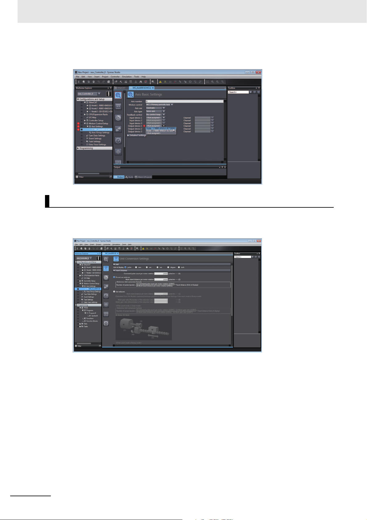
3 Configuring Axes and Axes Groups
3
Select the Servo Drive to use.
This setting allows you to use a Servo Drive as an axis.
Setting Axis Parameters
Click each of the icons in the Axis Parameter Settings Tab Page.
The settings for each icon are displayed on the Axis Parameter Settings Tab Page.
3-16
NY-series Industrial Panel PC / Industrial Box PC Motion Control User’s Manual (W559)
Page 71

3 Configuring Axes and Axes Groups
Precautions for Correct UsePrecautions for Correct Use
Additional Information
Right-click Axis Settings in the Multiview Explorer and select Axis Setting Table to enable setting the
axes parameters for all axes at the same time.
3-2 Axis Setting Procedure
3
3-2-2 Setting Procedure
When making operation settings such as the display unit, electronic gear (unit conversion formula), maximum velocity, or maximum acceleration/deceleration, be sure to use appropriate values for the operating conditions of the device.
Changing Axis Variable Names in the User Program
Perform the following two procedures to change Axis Variable names that are already used.
• Change the Axis Variable name in the variable table in the variable declarations.
• Change the Axis Variable name in the user program.
Even if you change the Axis Variable names in the variable table, the Axis Variable names in the
user program do not change. An error will occur if you use a variable name that is not declared in
the variable table, in the user program. Always change the names in both places.
NY-series Industrial Panel PC / Industrial Box PC Motion Control User’s Manual (W559)
3-17
Page 72

3 Configuring Axes and Axes Groups
Additional Information
Downloading to the Controller
Use the Synchronization menu command of the Sysmac Studio to download the project to the NYseries Controller.
1
Select Online from the Controller Menu. The Sysmac Studio goes online with the Controller.
2
Select Synchronization from the Controller Menu and then click the Transfer to Controller
Button.
Introduction to Servo Drive Settings
The MC Function Module connects to OMRON 1S-series Servo Drives with built-in EtherCAT
communications, G5-series Servo Drives with built-in EtherCAT communications, or NX-series
Pulse Output Units.
Connectable Servo Drive Models
You can connect the R88D-1SN-ECT, R88D-KN-ECT and R88D-KN-
ECT-L Servo Drives.
The R88D-KN-ECT-R Servo Drives support only Position Control Mode (Cyclic Synchronous Position Control Mode). Therefore, any functions that use Velocity Control Mode
(Cyclic Synchronous Velocity Control Mode) or Torque Control Mode (Cyclic Synchronous
Torque Control Mode) cannot be used.
Servo Drive Settings
The MC Function Module uses some of the input signals and functions of the Servo Drives.
Servo Drive signal wiring and object setting are required to use the MC Function Module
properly. Refer to A-1 Connecting the 1S-series Servo Drive or A-2 Connecting the G5-
series Servo Drive for specific settings.
Refer to the NX-series Position Interface Units User’s Manual (Cat. No. W524) for the settings to
use NX-series Pulse Output Units.
3-18
NY-series Industrial Panel PC / Industrial Box PC Motion Control User’s Manual (W559)
Page 73

3-3 Axes Groups
This section describes the axes groups of the MC Function Module.
3 Configuring Axes and Axes Groups
3-3-1 Introduction to Axes Groups
Use axes groups to perform complex operations on multiple axes, such as linear or circular interpolation. An axes group consists of multiple axes. Use the Sysmac Studio to set Axes Group Variables to
enable execution of axes group motion control instructions or to enable access of the status of the axes
group. The MC Function Module can handle up to 32 groups. The specifications for axes groups are
shown in the following table.
Item Specification
Number of axes groups 32 groups max.
Number of composition axes 4 axes max. per axes group
The following elements are related to the axes groups of the MC Function Module.
Configuration element Description Page
Axes group parameters The axes group parameters set the maximum interpolation veloc-
ity, maximum interpolation acceleration/deceleration, and other
items for the axes groups controlled by the MC Function Module.
Use the Sysmac Studio to set the axes group parameters.
Axes Group Variable Axes Group Variables are system-defined variables that include a
portion of the axes group parameters as well as the command
interpolation velocity, error information, and other monitor information for the axes groups controlled by the MC Function Module.
Axes Group Variables are created when you add an axes group
from the Multiview Explorer of the Sysmac Studio. The names of
the Axes Group Variables (called the Axes Group Variable names)
are set here.
Specifying axes groups
in the user program
In the user program, motion control is implemented with motion
control instructions. Motion control instructions that perform multiaxes coordinated control are used to create axes group commands. To control an axes group with axes group commands,
specify the axes group variable name of the system-defined variable or the axes group variable name that was set with the Sysmac
Studio for the AxesGroup in-out variable of the instruction.
3-3 Axes Groups
3
3-3-1 Introduction to Axes Groups
P. 3-20
P. 3-20
P. 3-23
NY-series Industrial Panel PC / Industrial Box PC Motion Control User’s Manual (W559)
3-19
Page 74
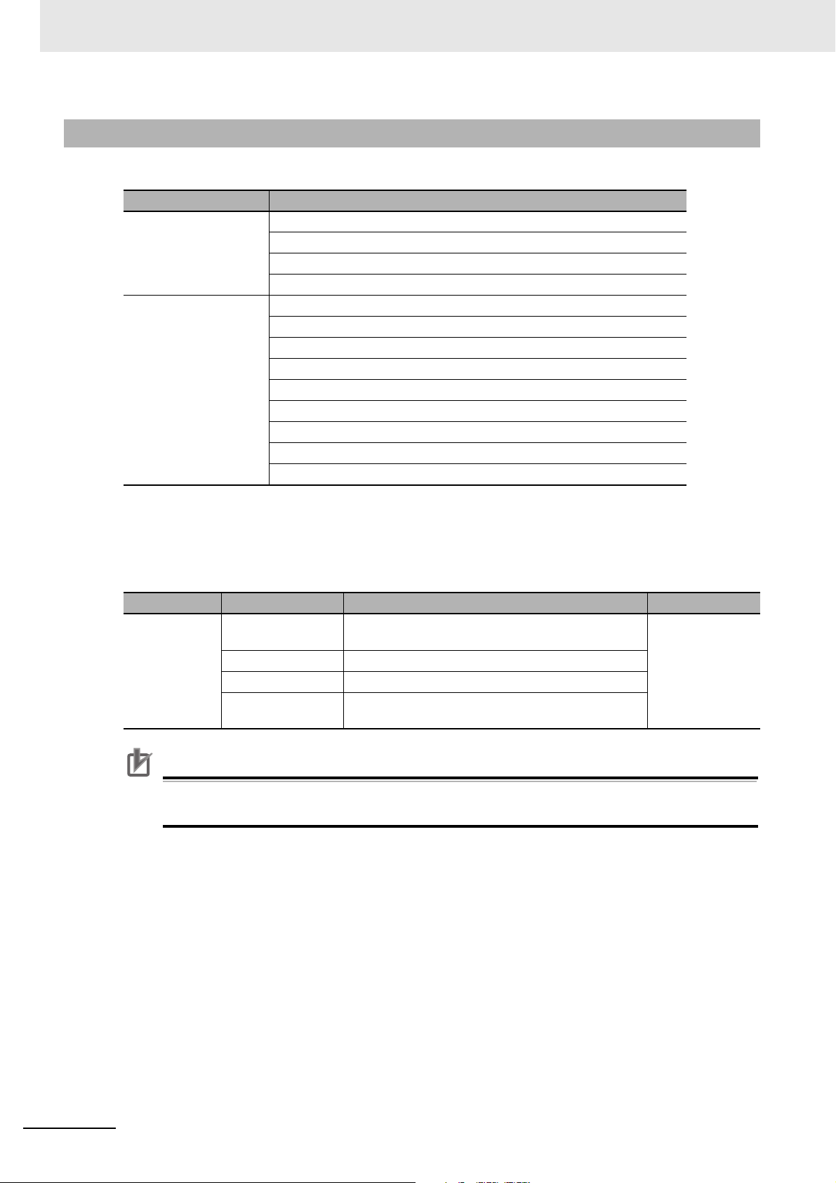
3 Configuring Axes and Axes Groups
Precautions for Correct UsePrecautions for Correct Use
3-3-2 Introduction to Axes Group Parameters
Axes Group Parameters
Classification Parameter name
Axes Group Basic Settings
Axes Group Operation
Settings
Axes Group Number
Axes Group Use
Composition
Composition Axes
Maximum Interpolation Velocity
Maximum Interpolation Acceleration
Maximum Interpolation Deceleration
Interpolation Acceleration/Deceleration Over
Interpolation Velocity Warning Value
Interpolation Acceleration Warning Value
Interpolation Deceleration Warning Value
Axes Group Stop Method
Correction Allowance Ratio
Refer to 5-3 Axes Group Parameters for details on axes group parameters.
Settings Required to Use an Axes Group
The following settings must be made to use the axes groups that are created with the Sysmac
Studio.
Classification Parameter name Setting Page
Axes Group
Basic Settings
Set appropriate values for the maximum interpolation velocity, stop method, and other items
based on the operating conditions.
Axes Group
Number
Axes Group Use Select Use.
Composition Select the axis composition to control.
Composition Axes This parameter sets the axes to assign to the axes
Axes group numbers are automatically set in the
order that the axes groups are created.
group.
P. 5 - 3 0
3-20
NY-series Industrial Panel PC / Industrial Box PC Motion Control User’s Manual (W559)
Page 75

3 Configuring Axes and Axes Groups
3-3-3 Introduction to Axes Group Variables
Axes Group Variables are system-defined variables for the setting information and the monitoring information, such as the actual position and error information, for the axes groups controlled by the MC
Function Module. When you create axes groups with the Sysmac Studio, Axes Group Variables are
registered in the variable table in the order that the axes groups are created. Axes Group Variables are
structures with a data type of _sGROUP_REF.
Axes Group Variable Names
Each Axes Group Variable in the MC Function Module has two variable names: The Axes Group
Variable name in the system-defined variables and the Axes Group Variable that is assigned when
the axes group is added on the Sysmac Studio. The Axes Group Variable names in the systemdefined variables are _MC_GRP[0] to _MC_GRP[31].
When you add axes groups on the Sysmac Studio, MC_Group000 to MC_Group031 are set by
default for _MC_GRP[0] to _MC_GRP[31]. The numbers are assigned in the order that the axes are
added. You can change each of these Axes Group Variable names as required from the Sysmac
Studio.
You can use either the Axes Group Variable names for the system-defined variables or the Axes
Group Variable names that are set on the Sysmac Studio to specify the Axes Group Variables in the
user program.
3-3 Axes Groups
3
3-3-3 Introduction to Axes Group Variables
Example When _MC_GRP[0-31] Is Used
Axes Group Variable name in the
system-defined variables (AT speci-
fication in global variable table
_MC_GRP[0] MC_Group000 Axes group 0
_MC_GRP[1] MC_Group001 Axes group 1
.
.
.
_MC_GRP[31] MC_Group031 Axes group 31
*1 An error will occur if you change the names in the AT column in the global variable table on the Sysmac Studio.
Default Axes Group Variable name when
axes group is added on Sysmac Studio
*1
)
.
.
.
Axes group number
example
.
.
.
NY-series Industrial Panel PC / Industrial Box PC Motion Control User’s Manual (W559)
3-21
Page 76

3 Configuring Axes and Axes Groups
Examples of Axes Group Variable Levels and Changing Axes Group
Variable Names
In the descriptions below, _MC_GRP[0] is used as an example. The same information applies to the
other axes group variables.
_MC_GRP[0] Axes Group Variables
_MC_GRP[0].Status Level that indicates the axes group status
.
.
.
_MC_GRP[0].Cmd Level that indicates the axes group command values
_MC_GRP[0].Cmd.Vel Variable that indicates the command interpolation velocity
_MC_GRP[0].Cmd.AccDec Variable that indicates the command interpolation accelera-
.
.
.
_MC_GRP[0].Cfg Level that indicates the axes group basic settings
_MC_GRP[0].Cfg.GrNo Variable that indicates the axes group number
_MC_GRP[0].Cfg.GrEnable Variable that indicates when the axes group is enabled
_MC_GRP[0].Kinematics Level that indicates the kinematics transformation settings
_MC_GRP[0].Kinematics.GrType Variable that indicates the axis composition
_MC_GRP[0].Kinematics.Axis[0] Variable that indicates the axis A0 composition axis
.
.
.
_MC_GRP[0].Kinematics.Axis[3] Variable that indicates the axis A3 composition axis
_MC_GRP[1] Axes Group Variable
.
.
.
tion/deceleration rate
Example: If MC_Group000 is changed to MyGroup1, then either MyGroup1.Cmd.Vel or
_MC_GRP[0].Cmd.Vel can be used as the variable that indicates the command inter-
polation velocity.
Refer to Axes Group Variables on page 6-30 for details on Axes Group Variables.
3-22
NY-series Industrial Panel PC / Industrial Box PC Motion Control User’s Manual (W559)
Page 77

3 Configuring Axes and Axes Groups
Specify an Axes
Group Variable
name.
In-out variable AxesGroup
Velocity
Error
ErrorID
CommandAborted
Jerk
Busy
Active
CoordSystem
MC_MoveLinear
Execute
Acceleration
AxesGroup AxesGroup
Done
Position
BufferMode
TransitionMode
MoveMode
MC_MoveLinear_instance
Deceleration
MyGroup1
MovLStart
MyGroup1
MyGroup1OnDone
MyGroup1OnBusy
MyGroup1OnActive
MyGroup1OnCA
MyGroup1OnError
MyGroup1OnErrorID
3-3-4 Specifying an Axes Group in the User Program
In the user program, an axes group variable name is specified for the in-out variable AxesGroup in
motion control instructions. In the following example, the Axes Group Variable name for the axes group
that was added for the system-defined Axes Group Variable name of _MC_GRP[0] has been changed
to MyGroup1 in the Sysmac Studio.
3-3 Axes Groups
3
3-3-4 Specifying an Axes Group in the User Program
NY-series Industrial Panel PC / Industrial Box PC Motion Control User’s Manual (W559)
You can also use the _MC_GRP[0] system-defined variable in place of MyGroup1.
Refer to 6-2 Motion Control Instructions for details on motion control instructions.
Refer to the instruction descriptions in the NY-series Motion Control Instructions Reference Manual
(Cat. No. W561) for details on motion control instructions.
3-23
Page 78

3 Configuring Axes and Axes Groups
START
END
Start the Sysmac Studio.
Add an axes group.
Set the axes group parameters.
Go online and synchronize the data.
Transfer the project to the Controller.
3-4 Setting Procedures for Axes Groups
This section gives the procedures to use the Sysmac Studio to set up an axes group. No configuration
is required if you are not going to use any axes group command instructions, such as linear interpolation or circular interpolation.
3-4-1 Setting Procedure for an Axes Group
3-4-2 Setting Procedure
This section gives the procedures to use the Sysmac Studio to set up an axes group in a project that
already contains the axes.
Starting the Sysmac Studio
1
Start the Sysmac Studio and open the project.
3-24
NY-series Industrial Panel PC / Industrial Box PC Motion Control User’s Manual (W559)
Page 79

3 Configuring Axes and Axes Groups
Adding an Axes Group
1
Right-click Axes Group Settings in the Multiview Explorer and select Axes Group Settings
from the Add Menu.
An axes group is added to the Multiview Explorer. The default name for the new axes group is
MC_Group000.
3-4 Setting Procedures for Axes Groups
3
3-4-2 Setting Procedure
Copying an Axes Group
You can also create an axes group by copying an axes group from a project.
NY-series Industrial Panel PC / Industrial Box PC Motion Control User’s Manual (W559)
3-25
Page 80

3 Configuring Axes and Axes Groups
Setting Axes Group Parameters
1
Right-click an axes group in the Multiview Explorer and select Edit from the menu.
The Axes Group Basic Settings are displayed in the Axes Group Parameter Settings Tab Page.
2
Select Used axes group in the Axes group use Box.
3-26
NY-series Industrial Panel PC / Industrial Box PC Motion Control User’s Manual (W559)
Page 81

3 Configuring Axes and Axes Groups
3
Select the composition of the axes group in the Composition Box. A 2-axis composition is
selected in the following example.
4
Assign the axis to use in the Logical axes Box.
3-4 Setting Procedures for Axes Groups
3
3-4-2 Setting Procedure
5
Click the bottom icon. The Axes Group Operation Settings Display is displayed.
Set appropriate values for the settings based on the operating conditions of the device.
NY-series Industrial Panel PC / Industrial Box PC Motion Control User’s Manual (W559)
3-27
Page 82

3 Configuring Axes and Axes Groups
Additional Information
Changing Axes Group Variable Names in the User Program
Perform the following two procedures to change Axes Group Variable names that are already
used.
• Change the Axes Group Variable name in the variable table in the variable declarations.
• Change the Axes Group Variable name in the user program.
Even if you change the Axes Group Variable names in the variable table, the Axes Group Variable names in the user program do not change. An error will occur if you use a variable name
that is not declared in the variable table, in the user program. Always change the names in both
places.
Downloading to the Controller
Use the Synchronization menu command of the Sysmac Studio to download the project to the NYseries Controller.
1
Select Online from the Controller Menu. The Sysmac Studio goes online with the Controller.
2
Select Synchronization from the Controller Menu and then click the Transfer to Controller
Button.
3-28
NY-series Industrial Panel PC / Industrial Box PC Motion Control User’s Manual (W559)
Page 83

Checking Wiring from the Sysmac
Studio
This section describes the MC Test Run operations of the Sysmac Studio. You can use
the MC Test Run to monitor sensor signals, check motor wiring, and more, all without
any programming.
4-1 Functions of the Sysmac Studio . . . . . . . . . . . . . . . . . . . . . . . . . . . . . . . . . 4-2
4-1-1 MC Test Run Function . . . . . . . . . . . . . . . . . . . . . . . . . . . . . . . . . . . . . . . . . . . 4-2
4-1-2 Application Procedure . . . . . . . . . . . . . . . . . . . . . . . . . . . . . . . . . . . . . . . . . . . 4-4
4-1-3 Axis Parameter Setting Example . . . . . . . . . . . . . . . . . . . . . . . . . . . . . . . . . . . 4-5
4-1-4 Starting the MC Test Run Function . . . . . . . . . . . . . . . . . . . . . . . . . . . . . . . . . 4-6
4-2 Monitoring Sensor Signals . . . . . . . . . . . . . . . . . . . . . . . . . . . . . . . . . . . . . . 4-7
4-3 Checking Motor Operation . . . . . . . . . . . . . . . . . . . . . . . . . . . . . . . . . . . . . . 4-8
4-3-1 Turning ON the Servo . . . . . . . . . . . . . . . . . . . . . . . . . . . . . . . . . . . . . . . . . . . 4-8
4-3-2 Jogging . . . . . . . . . . . . . . . . . . . . . . . . . . . . . . . . . . . . . . . . . . . . . . . . . . . . . . 4-8
4-3-3 Homing . . . . . . . . . . . . . . . . . . . . . . . . . . . . . . . . . . . . . . . . . . . . . . . . . . . . . . 4-9
4-3-4 Absolute Positioning . . . . . . . . . . . . . . . . . . . . . . . . . . . . . . . . . . . . . . . . . . . 4-10
4-3-5 Relative Positioning . . . . . . . . . . . . . . . . . . . . . . . . . . . . . . . . . . . . . . . . . . . . .4-11
4
NY-series Industrial Panel PC / Industrial Box PC Motion Control User’s Manual (W559)
4-1
Page 84

4 Checking Wiring from the Sysmac Studio
4-1 Functions of the Sysmac Studio
This section describes how to use the MC test run function to check wiring and basic settings. You can
use the MC test run function in the Sysmac Studio to check wiring without any programming.
4-1-1 MC Test Run Function
The MC test run operation supports the following functions.
Category
Axis operation Deceleration
Function Description Setting/monitor item
stop
Servo
ON/OFF
Resetting
errors
Jogging Jogging is performed in the positive or negative
Absolute positioning
Relative positioning
Homing Homing is performed using the homing parame-
A deceleration stop is performed during the MC
Tes t Ru n .
The Servo is turned ON and OFF. ---
The errors in the MC Function Module are
reset.
direction.
Absolute positioning is performed.
Relative positioning is performed. Travel Distance
ter settings.
*
---
---
Target Velocity
Acceleration/Deceleration
Target Position
Target Velocity
Acceleration/Deceleration
Jerk
Target Velocity
Acceleration/Deceleration
Jerk
Homing Parameters
4-2
NY-series Industrial Panel PC / Industrial Box PC Motion Control User’s Manual (W559)
Page 85

4 Checking Wiring from the Sysmac Studio
Category
Monitoring Error list The errors in the MC Function Module are mon-
Function Description Setting/monitor item
itored.
Axis status The status of the axes is monitored. Axis Ready-to-execute
Actual position monitor
Actual velocity monitor
Servo Drive
status
Input signals The status of the input signals are monitored. Positive Limit Input
The actual position is monitored. Command and Actual Cur-
The actual velocity is monitored. Command and Actual Cur-
The status of the Servo Drive is monitored. Servo ON/OFF
MC Common Errors
Axis Errors
Axes Group Errors
Standstill
Discrete Motion
Continuous Motion
Homing
Stopping
Home Defined
In Home Position
rent Positions
rent Velocities
Servo Ready
Main Power
Negative Limit Input
Immediate Stop Input
Home Proximity Input
Home Input
External Latch Inputs 1 to 2
4-1 Functions of the Sysmac Studio
4
4-1-1 MC Test Run Function
* When the Count Mode of the axis is set to Rotary Mode, positioning is performed toward the target position in the
positive direction. For details, refer to the MC_MoveAbsolute (Absolute Positioning) instruction in the NY-series
Motion Control Instructions Reference Manual (Cat. No. W561).
Note You can use MC Test Runs for OMRON 1S-series Servo Drives, G5-series Servo Drives, or NX-series Pulse
Output Units. Do not use it with servo drives from any other manufacturer.
NY-series Industrial Panel PC / Industrial Box PC Motion Control User’s Manual (W559)
4-3
Page 86

4 Checking Wiring from the Sysmac Studio
Precautions for Correct UsePrecautions for Correct Use
Additional Information
Section 3 Configuring Axes and
Axes Groups
Section 4 Checking Wiring
from the Sysmac Studio
4-1-2 Application Procedure
Before you perform an MC Test Run, check the following two items.
• Are the Sysmac Studio and Controller connected and are they online?
• Is the MC Test Run Mode currently in use from any other copy of the Sysmac Studio?
After you have confirmed these two items, perform the following operations as instructed.
START
Setup
Starting the MC
test run function
Checking wiring
Checking motor
operation
Checking electronic
gear settings
Confirming homing
Create the EtherCAT slave configuration, add axes,
assign the axes, and set the axis parameters.
Start the MC test run function.
Confirm sensor wiring.
Use jogging to check the direction of the motor.
Perform relative positioning to check the travel distance.
Perform homing to check the homing operation.
• When one of the following operations is performed for a command from the Sysmac Studio,
the Servomotor will operate at the set velocity: Servo ON, jogging, relative positioning, absolute positioning, or homing. Always confirm that it is safe for the Servomotor to operate before
executing any of these operations.
• When operating the Controller from the Sysmac Studio, always install external emergency cir-
cuits so that the Servomotor can be stopped safely whenever necessary. The Sysmac Studio
may not be able to send commands under some circumstances, e.g., if an error occurs in the
computer.
• Set the EtherCAT communications and establish communications before you attempt to per-
form operation from the Sysmac Studio.
• Refer to the NX-series Position Interface Units User’s Manual (Cat. No. W524) for the proce-
dures for the NX-series Position Interface Units.
You can perform the following operations to end the MC test run function at any time.
• Select MC Test Run
• Right-click the axis in the Multiview Explorer of the Sysmac Studio and select Stop MC Test
Run from the menu.
• Close the MC Test Run Tab Page on the Sysmac Studio.
• Exit the Sysmac Studio.
Refer to the Sysmac Studio Version 1 Operation Manual (Cat. No. W504) for specific procedures.
4-4
−
Stop from the Controller Menu of the Sysmac Studio.
NY-series Industrial Panel PC / Industrial Box PC Motion Control User’s Manual (W559)
Page 87

4 Checking Wiring from the Sysmac Studio
4-1-3 Axis Parameter Setting Example
Set the following axis parameters before you execute the MC Test Run Mode in the Sysmac Studio.
The following setting example is for a one-axis device.
Servomotor
Encoder resolution: 20 bits/rotation
Encoder Output Pulse Count per Motor Rotation
20 bits = 1,048,576
10 mm
Ball screw
Ball screw pitch: 10 mm
1 rotation
Parameter name Setting
Axis Variable Name
Axis Number
Axis1
*2
1
*1
Axis Use Used axis
Axis Type Servo axis
Input Device/Output Device
*3
1
Unit of Display μm
Command Pulse Count Per Motor Rotation
Work Travel Distance Per Motor Rotation
Maximum Velocity
Maximum Jog Velocity
Maximum Acceleration
Maximum Deceleration
1,048,576
10,000
500,000
50,000
5,000,000
5,000,000
*4
*4
*5
*6
*7
*7
Software Limits Immediate stop for command position
Positive Software Limit
Negative Software Limit
500,000
0
*8
*8
Count Mode Linear Mode
4-1 Functions of the Sysmac Studio
4
4-1-3 Axis Parameter Setting Example
*1 If there is more than one axis, a different variable name is set for each axis.
*2 If there is more than one axis, a different value is set for each axis.
*3 Set the same node address as for the Servo Drive.
If there is more than one axis, a different value is set for each axis.
*4 The position command unit will be 1 μm.
*5 The maximum velocity will be 3,000 r/min = 30 m/min = 0.5 m/s = 500,000 μm/s.
*6 The maximum jog velocity will be 10% of the maximum velocity, i.e., 0.05 m/s = 50,000 μm/s.
*7 The maximum acceleration and the maximum deceleration will be 5 m/s
The acceleration time to the maximum velocity (3,000 r/min) will be 0.1 s.
*8 Set a value that is within the movable range of the device.
The positive software limit is set to 50 cm = 500,000 μm.
NY-series Industrial Panel PC / Industrial Box PC Motion Control User’s Manual (W559)
2
.
4-5
Page 88

4 Checking Wiring from the Sysmac Studio
4-1-4 Starting the MC Test Run Function
The MC Test Run Mode is started from the Sysmac Studio.
1
Start the Sysmac Studio and open a project in which the axis settings are completed.
2
Select Online from the Controller Menu. The Sysmac Studio goes online with the Controller.
3
Select MC Test Run − Start from the Controller Menu.
When the following caution dialog box appears, read the message carefully. After you confirm
safety, click the OK Button.
The MC Test Run Tab Page is displayed.
4-6
NY-series Industrial Panel PC / Industrial Box PC Motion Control User’s Manual (W559)
Page 89

4 Checking Wiring from the Sysmac Studio
4-2 Monitoring Sensor Signals
You can use the input signal display to check sensor signal wiring.
1
Select the axis to check on the MC Test Run Tab Page.
4-2 Monitoring Sensor Signals
2
Check to see if the signals turn ON and OFF properly on the monitor screen by turning ON and
OFF the sensor connected to each input signal.
4
NY-series Industrial Panel PC / Industrial Box PC Motion Control User’s Manual (W559)
4-7
Page 90

4 Checking Wiring from the Sysmac Studio
Precautions for Correct UsePrecautions for Correct Use
4-3 Checking Motor Operation
Use the functions of the MC Test Run to check motor operation.
4-3-1 Turning ON the Servo
You can use the Servo ON Button to turn the Servo ON and OFF.
1
Select the axis for which to turn ON the Servo.
2
Click the Servo ON Button to turn ON the Servo.
3
Click the Servo OFF Button to turn OFF the Servo.
• When one of the following operations is performed for a command from the Sysmac Studio,
the Servomotor will operate at the set velocity: Servo ON, jogging, relative positioning, absolute positioning, or homing. Always confirm that it is safe for the Servomotor to operate before
executing any of these operations.
• When you operate the Controller from the Sysmac Studio, always install external emergency
circuits so that the Servomotor can be stopped safely whenever necessary. The Sysmac Studio may not be able to send commands under some circumstances, e.g., if an error occurs in
the computer.
• Set the EtherCAT communications and establish communications before you attempt to per-
form operation from the Sysmac Studio.
• If you use an NX-series Pulse Output Unit, you must provide a separate means to turn the
power supply to the motor drive ON and OFF. Refer to the NX-series Position Interface Units
User’s Manual (Cat. No. W524) for details.
4-3-2 Jogging
1
Select the axis to jog on the Jogging Tab Page of the MC Test Run Tab Page.
2
Click the Servo ON Button to turn ON the Servo.
3
Enter the target velocity, acceleration rate, and deceleration rate, and then press the Apply Button.
4-8
NY-series Industrial Panel PC / Industrial Box PC Motion Control User’s Manual (W559)
Page 91

4
Additional Information
Click the or Button.
The motor will operate in either the positive or negative direction while one of these buttons is
clicked. Check to see if the motor operates in the set direction.
4-3-3 Homing
4 Checking Wiring from the Sysmac Studio
1
Set the homing parameters in the Homing Settings on the Axis Parameter Settings Tab Page.
2
Click the Homing Tab on the MC Test Run Tab Page.
The following dialog box is displayed.
4-3 Checking Motor Operation
4
4-3-3 Homing
3
Select the axis to home.
4
Click the Servo ON Button to turn ON the Servo.
5
Click the Apply homing parameters Button.
6
Click the Button.
Check to see if the homing operation agrees with the settings.
• When you click the Homing Settings Button, the Homing Settings are displayed on the Axis
Parameter Settings Tab Page. Set the homing parameters.
• If the homing parameters were set in advance, click the Apply homing parameters Button to
apply those settings.
NY-series Industrial Panel PC / Industrial Box PC Motion Control User’s Manual (W559)
4-9
Page 92
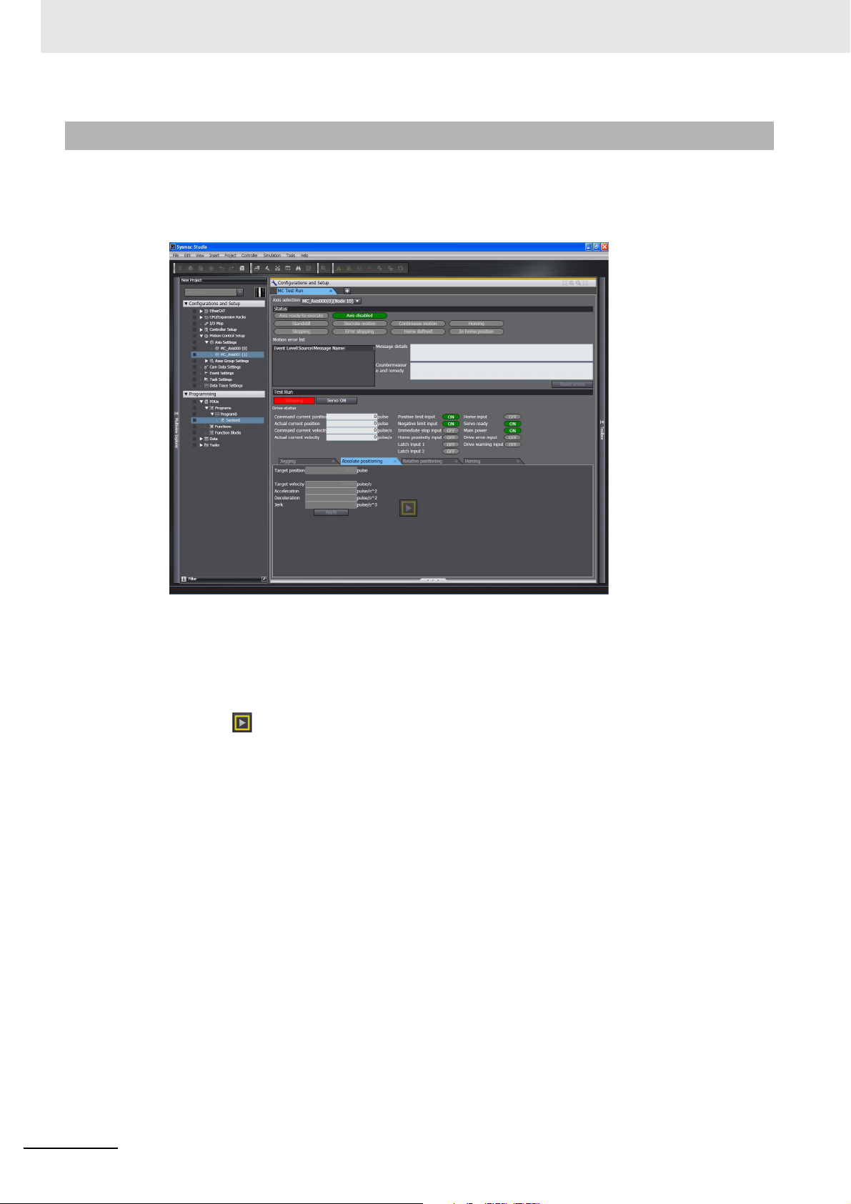
4 Checking Wiring from the Sysmac Studio
4-3-4 Absolute Positioning
1
Click the Absolute positioning Tab on the MC Test Run Tab Page.
The following dialog box will appear.
2
Select the axis to perform absolute positioning.
3
Click the Servo ON Button to turn ON the Servo.
4
Enter the target position, target velocity, acceleration rate, deceleration rate, and jerk, and then
click the Apply Button.
5
Click the Button. Absolute positioning will start.
Check to see if positioning agrees with the settings.
4-10
NY-series Industrial Panel PC / Industrial Box PC Motion Control User’s Manual (W559)
Page 93

4-3-5 Relative Positioning
1
Click the Relative positioning Tab on the MC Test Run Tab Page.
The following dialog box will appear.
4 Checking Wiring from the Sysmac Studio
4-3 Checking Motor Operation
2
Select the axis to perform relative positioning.
3
Click the Servo ON Button to turn ON the Servo.
4
Enter the target travel distance, target velocity, acceleration rate, deceleration rate, and jerk,
and then click the Apply Button.
5
Click the Button. Relative positioning will start.
Check to see if the travel distance agrees with the settings.
4
4-3-5 Relative Positioning
NY-series Industrial Panel PC / Industrial Box PC Motion Control User’s Manual (W559)
4-11
Page 94

4 Checking Wiring from the Sysmac Studio
4-12
NY-series Industrial Panel PC / Industrial Box PC Motion Control User’s Manual (W559)
Page 95

Motion Control Parameters
This section explains about axis parameters and axes group parameters used for
motion control.
5-1 Introduction . . . . . . . . . . . . . . . . . . . . . . . . . . . . . . . . . . . . . . . . . . . . . . . . . . 5-2
5-2 Axis Parameters . . . . . . . . . . . . . . . . . . . . . . . . . . . . . . . . . . . . . . . . . . . . . . . 5-5
5-2-1 Axis Parameters . . . . . . . . . . . . . . . . . . . . . . . . . . . . . . . . . . . . . . . . . . . . . . . 5-5
5-2-2 Axis Basic Settings . . . . . . . . . . . . . . . . . . . . . . . . . . . . . . . . . . . . . . . . . . . . . 5-7
5-2-3 Unit Conversion Settings . . . . . . . . . . . . . . . . . . . . . . . . . . . . . . . . . . . . . . . . 5-10
5-2-4 Operation Settings . . . . . . . . . . . . . . . . . . . . . . . . . . . . . . . . . . . . . . . . . . . . . 5-17
5-2-5 Other Operation Settings . . . . . . . . . . . . . . . . . . . . . . . . . . . . . . . . . . . . . . . . 5-21
5-2-6 Limit Settings . . . . . . . . . . . . . . . . . . . . . . . . . . . . . . . . . . . . . . . . . . . . . . . . . 5-22
5-2-7 Position Count Settings . . . . . . . . . . . . . . . . . . . . . . . . . . . . . . . . . . . . . . . . . 5-22
5-2-8 Servo Drive Settings . . . . . . . . . . . . . . . . . . . . . . . . . . . . . . . . . . . . . . . . . . . 5-24
5-2-9 Homing Settings . . . . . . . . . . . . . . . . . . . . . . . . . . . . . . . . . . . . . . . . . . . . . . 5-25
5-2-10 Axis Parameter Setting Example . . . . . . . . . . . . . . . . . . . . . . . . . . . . . . . . . . 5-26
5-3 Axes Group Parameters . . . . . . . . . . . . . . . . . . . . . . . . . . . . . . . . . . . . . . . 5-29
5-3-1 Axes Group Parameters . . . . . . . . . . . . . . . . . . . . . . . . . . . . . . . . . . . . . . . . 5-29
5-3-2 Axes Group Basic Settings . . . . . . . . . . . . . . . . . . . . . . . . . . . . . . . . . . . . . . 5-30
5-3-3 Axes Group Operation Settings . . . . . . . . . . . . . . . . . . . . . . . . . . . . . . . . . . . 5-32
5-3-4 Enabling an Axes Group . . . . . . . . . . . . . . . . . . . . . . . . . . . . . . . . . . . . . . . . 5-34
5
NY-series Industrial Panel PC / Industrial Box PC Motion Control User’s Manual (W559)
5-1
Page 96

5 Motion Control Parameters
Sysmac Studio
Downloaded.*2
Uploaded.*2
NY-series Controller
MC common parameter settings*1
Axis parameter settings
Axes group parameter settings
• After the
settings are
downloaded
• When power is
turned ON
MC common parameter settings*1
Axis parameter settings
Axes group parameter settings
Non-volatile memory Main memory
MC_Write instruction
or other instructions
MC_WriteAxisPara
meter/MC_ReadAx
isParameter
instructions
Temporary
changes to some
parameters
Temporarily
changes/reads to
some axis
parameter settings
Data movement or
other instructions
User program
Accessing some
parameters as
variables
5-1 Introduction
You can use motion control instructions to perform single-axis operations and multi-axes operations on
axes groups with the NY-series Controller’s MC Function Module. Axis and axes group parameters are
used to set these operations. Axis parameters must be set, but axes group parameters are not required
if you do not use multi-axes operations for axes groups.
These parameters are called motion control parameter settings (MC parameter settings).
*1 There are no MC Common Parameter Settings for the current version of the MC Function Module.
*2 Use the Synchronization menu command of the Sysmac Studio to upload and download the project.
Data Flow for Setting MC Parameters
• Download your MC Parameter Settings to the NY-series Controller using the Sysmac Studio to
save those settings in the non-volatile memory in the Industrial PC. When you upload the MC
Parameter Settings to the Sysmac Studio, the MC Parameter Settings that were saved in the nonvolatile memory are uploaded.
• The settings that were saved in the non-volatile memory are applied to the main memory after you
download them or when the power is turned ON.
• If there are no problems with the saved settings, the MC Function Module executes control based
on the settings in the main memory.
• The settings of some of the parameters can be accessed as system-defined variables for motion
control.
• You can upload and download MC parameter settings regardless of the NY-series Controller
mode or the status of the MC Function Module.
• When you start the download process, all axes in motion will stop immediately.
5-2
NY-series Industrial Panel PC / Industrial Box PC Motion Control User’s Manual (W559)
Page 97

5 Motion Control Parameters
Version Information
Precautions for Correct UsePrecautions for Correct Use
If an NY-series Controller with unit version 1.14 or later and Sysmac Studio version 1.17 or
higher are combined, commands to the I/O devices can continuously be sent even when the
download process is in progress.
For the NY-series Controller with unit version 1.12 or earlier, sending commands to the I/O
devices is stopped when the download process is executed.
Refer to the NY-series Industrial Panel PC / Industrial Box PC Software User’s Manual (Cat. No.
W558) for how to set to stop or continue sending commands to the I/O devices when the download process starts.
Stopping sending commands to I/O devices
Servo is turned OFF during the download, and the axis status will be Disable (Axis Disabled).
Continuing sending commands to I/O devices
The following status immediately before downloading is maintained during the download:
the Servo ON state for the MC_Power instruction and the output torque limit for the MC_SetTorqueLimit instruction.
The Servo ON state and torque limit are maintained even if the MC_Power and MC_SetTorqueLimit instructions are deleted from the user program after the program is updated by
downloading.
Overwriting MC Parameters with Programming Instructions
• You can use motion control instructions like the MC_Write (Write MC Setting), MC_ChangeAxes-
InGroup (Change Axes in Group) or MC_WriteAxisParameter (Write Axis Parameters) instruction
to change the settings of some of the MC parameters in the main memory while the user program
is running.
• If the specified set value is outside the valid range, the Error output variable from the instruction
changes to TRUE and the MC parameter setting is not changed.
• Changes to MC parameter settings become valid in either of the following two situations.
• The axis or axes group is stopped and you execute an instruction for an axis command or
axes group command.
• You set the Buffer Mode Selection for the instruction to Aborting and execute more than one
instruction.
• For details on MC_Write (Write MC Setting), MC_ChangeAxesInGroup (Change Axes in Group),
MC_WriteAxisParameter (Write Axis Parameters) and other instructions, refer to the NY-series
Motion Control Instructions Reference Manual (Cat. No. W561).
5-1 Introduction
5
• Changes to the MC Parameter Settings that are made with the MC_Write (Write MC Setting)
instruction are saved in the main memory in the Industrial PC. They are not saved in the builtin non-volatile memory in the Industrial PC. Therefore, if you cycle the power supply or download the settings from the Sysmac Studio, the parameter settings in the non-volatile memory
are restored. Also, you cannot upload the data in the main memory from the Sysmac Studio. If
you need to save settings to the non-volatile memory, use the Sysmac Studio to change the
parameter settings and then download those settings to the NY-series Controller.
• To maintain the MC_Power (Power Servo) and MC_SetTorqueLimit instructions after down-
loading, set Retain attribute of the input bits for the instructions to Retain.
• You can use the following instructions to change the settings of the MC parameters.
• MC_Write (Write MC Setting) instruction
• MC_ChangeAxesInGroup (Change Axes in Group) instruction
NY-series Industrial Panel PC / Industrial Box PC Motion Control User’s Manual (W559)
5-3
Page 98

5 Motion Control Parameters
• MC_ChangeAxisUse (Changing Axis Use) instruction
• MC_WriteAxisParameter (Write Axis Parameters) instruction
• Refer to the NX-series Position Interface Units User’s Manual (Cat. No. W524) for information
on using the NX-series Position Interface Units.
5-4
NY-series Industrial Panel PC / Industrial Box PC Motion Control User’s Manual (W559)
Page 99

5-2 Axis Parameters
The axis parameters set the maximum velocity, jerk, homing, and other items for the axes controlled by
the MC Function Module.
The number of axis parameters provided is the same as the maximum number of controlled axes for
each model. The maximum number of controlled axes varies depending on the model. Refer to 1-4-2
Performance Specifications on page 1-6 for details.
The same parameter settings are provided for each axis. This section describes only the parameters for
axis 1.
5 Motion Control Parameters
5-2-1 Axis Parameters
Use the Sysmac Studio to set the axis parameters for each axis.
Classification Parameter name
Axis Basic
Settings
Unit Conversion Settings
Operation Settings
Operation Settings
Axis Number --- --- OK P. 5-7
Axis Use
Axis Type --- --- OK
Input Device/Output Device --- --- OK
Unit of Display
Command Pulse Count Per Motor Rotation
Work Travel Distance Per Motor Rotation OK
Reducer Use
Work Travel Distance Per Rotation
Work Gear Ratio
Motor Gear Ratio
Maximum Velocity
Start Velocity
Maximum Jog Velocity ---
Maximum Acceleration ---
Maximum Deceleration ---
Acceleration/Deceleration Over ---
Operation Selection at Reversing ---
Velocity Warning Value OK MC_Write
Acceleration Warning Value ---
Deceleration Warning Value ---
Positive Torque Warning Value
Negative Torque Warning Value
In-position Range
In-position Check Time OK ---
Actual Velocity Filter Time Constant
Zero Position Range ---
5-2 Axis Parameters
Temporary changes
Support
OK
OK
OK
*4
*4
OK
OK
Applicable
instruction
MC_ChangeA
xisUse
MC_WriteAxisParameter
MC_WriteAxisParameter
MC_WriteAxisParameter
MC_WriteAxisParameter
*1
Reading
variables
OK
OK P. 5-10
*3
OK
---
---
---
---
--- P. 5-17
*3
---
---
*3
---
---
---
--- P. 5-17
*3
Page
*2
5
5-2-1 Axis Parameters
NY-series Industrial Panel PC / Industrial Box PC Motion Control User’s Manual (W559)
5-5
Page 100

5 Motion Control Parameters
Temporary changes
Classification Parameter name
Other Operation Settings
Immediate Stop Input Stop Method
Limit Input Stop Method ---
Support
OK
Applicable
instruction
MC_WriteAxisParameter
Drive Error Reset Monitoring Time ---
Maximum Positive Torque Limit ---
Maximum Negative Torque Limit ---
Immediate Stop Input Logic Inversion
Positive Limit Input Logic Inversion
Negative Limit Input Logic Inversion
Home Proximity Input Logic Inversion
Limit Settings Software Limits OK MC_Write
Positive Software Limit ---
Negative Software Limit ---
MC_WriteAxisParameter
Following Error Over Value ---
Following Error Warning Value ---
Position Count
Settings
Count Mode
Modulo Maximum Position Setting Value
OK
MC_WriteAxisParameter
Modulo Minimum Position Setting Value
Encoder Type --- --- ---
Servo Drive
Settings
Homing Settings
Modulo Maximum Position Setting Value --- --- --- P. 5-24
Modulo Minimum Position Setting Value --- --- ---
PDS State Control Method
Homing Method
Home Input Signal ---
--- --- ---
OK
MC_WriteAxisParameter
Homing Start Direction ---
Home Input Detection Direction ---
Operation Selection at Positive Limit
Input
Operation Selection at Negative Limit
Input
Homing Velocity ---
Homing Approach Velocity ---
Homing Acceleration ---
Homing Deceleration ---
Homing Jerk ---
Home Input Mask Distance ---
Home Offset ---
Homing Holding Time ---
Homing Compensation Value ---
Homing Compensation Velocity ---
*1
Reading
variables
--- P. 5-21
*3
---
---
---
---
--- P. 5-22
*3
--- P. 5-22
*3
OK
OK
--- P. 5-25
*3
---
---
Page
*2
5-6
*1 This column indicates if you can use instructions to temporarily change the settings.
*2 Indicates whether you can access the parameter with a system-defined variable for motion control in the user
program.
*3 The parameters that can be temporarily changed with the MC_WriteAxisParameter instruction can be read
with the MC_ReadAxisParameter instruction.
*4 This parameter is enabled only for torque control.
NY-series Industrial Panel PC / Industrial Box PC Motion Control User’s Manual (W559)
 Loading...